WO2022138570A1 - Device for detecting paper splice part of cardboard sheet, and device for producing cardboard sheet - Google Patents
Device for detecting paper splice part of cardboard sheet, and device for producing cardboard sheet Download PDFInfo
- Publication number
- WO2022138570A1 WO2022138570A1 PCT/JP2021/047052 JP2021047052W WO2022138570A1 WO 2022138570 A1 WO2022138570 A1 WO 2022138570A1 JP 2021047052 W JP2021047052 W JP 2021047052W WO 2022138570 A1 WO2022138570 A1 WO 2022138570A1
- Authority
- WO
- WIPO (PCT)
- Prior art keywords
- sheet
- corrugated cardboard
- paper
- mark
- roll
- Prior art date
Links
- 239000000123 paper Substances 0.000 title claims abstract description 290
- 238000001514 detection method Methods 0.000 claims abstract description 114
- 238000004519 manufacturing process Methods 0.000 claims description 36
- 230000014759 maintenance of location Effects 0.000 claims description 20
- 238000010030 laminating Methods 0.000 claims description 14
- 239000007921 spray Substances 0.000 description 37
- 230000002950 deficient Effects 0.000 description 32
- 239000003292 glue Substances 0.000 description 28
- 238000004026 adhesive bonding Methods 0.000 description 24
- 230000002093 peripheral effect Effects 0.000 description 22
- 238000007599 discharging Methods 0.000 description 20
- 238000000034 method Methods 0.000 description 12
- 229910052751 metal Inorganic materials 0.000 description 10
- 239000002184 metal Substances 0.000 description 10
- 238000004804 winding Methods 0.000 description 9
- 238000010586 diagram Methods 0.000 description 7
- 238000012986 modification Methods 0.000 description 7
- 230000004048 modification Effects 0.000 description 7
- 238000011144 upstream manufacturing Methods 0.000 description 7
- 230000001133 acceleration Effects 0.000 description 6
- 238000006073 displacement reaction Methods 0.000 description 6
- 238000013459 approach Methods 0.000 description 5
- 238000005304 joining Methods 0.000 description 5
- 229910052782 aluminium Inorganic materials 0.000 description 4
- XAGFODPZIPBFFR-UHFFFAOYSA-N aluminium Chemical compound [Al] XAGFODPZIPBFFR-UHFFFAOYSA-N 0.000 description 4
- 238000002788 crimping Methods 0.000 description 4
- 238000010438 heat treatment Methods 0.000 description 4
- 230000005540 biological transmission Effects 0.000 description 3
- 230000007423 decrease Effects 0.000 description 3
- 239000000853 adhesive Substances 0.000 description 2
- 230000001070 adhesive effect Effects 0.000 description 2
- 230000002238 attenuated effect Effects 0.000 description 2
- 239000011248 coating agent Substances 0.000 description 2
- 238000000576 coating method Methods 0.000 description 2
- 238000009826 distribution Methods 0.000 description 2
- 238000012545 processing Methods 0.000 description 2
- 238000012546 transfer Methods 0.000 description 2
- 239000003795 chemical substances by application Substances 0.000 description 1
- 230000008602 contraction Effects 0.000 description 1
- 238000001816 cooling Methods 0.000 description 1
- 238000005520 cutting process Methods 0.000 description 1
- 230000007547 defect Effects 0.000 description 1
- 230000000694 effects Effects 0.000 description 1
- 230000001678 irradiating effect Effects 0.000 description 1
- 238000005259 measurement Methods 0.000 description 1
- 238000007790 scraping Methods 0.000 description 1
Images


Classifications
-
- B—PERFORMING OPERATIONS; TRANSPORTING
- B65—CONVEYING; PACKING; STORING; HANDLING THIN OR FILAMENTARY MATERIAL
- B65H—HANDLING THIN OR FILAMENTARY MATERIAL, e.g. SHEETS, WEBS, CABLES
- B65H26/00—Warning or safety devices, e.g. automatic fault detectors, stop-motions, for web-advancing mechanisms
- B65H26/02—Warning or safety devices, e.g. automatic fault detectors, stop-motions, for web-advancing mechanisms responsive to presence of irregularities in running webs
-
- B—PERFORMING OPERATIONS; TRANSPORTING
- B31—MAKING ARTICLES OF PAPER, CARDBOARD OR MATERIAL WORKED IN A MANNER ANALOGOUS TO PAPER; WORKING PAPER, CARDBOARD OR MATERIAL WORKED IN A MANNER ANALOGOUS TO PAPER
- B31F—MECHANICAL WORKING OR DEFORMATION OF PAPER, CARDBOARD OR MATERIAL WORKED IN A MANNER ANALOGOUS TO PAPER
- B31F1/00—Mechanical deformation without removing material, e.g. in combination with laminating
- B31F1/20—Corrugating; Corrugating combined with laminating to other layers
- B31F1/24—Making webs in which the channel of each corrugation is transverse to the web feed
- B31F1/26—Making webs in which the channel of each corrugation is transverse to the web feed by interengaging toothed cylinders cylinder constructions
- B31F1/28—Making webs in which the channel of each corrugation is transverse to the web feed by interengaging toothed cylinders cylinder constructions combined with uniting the corrugated webs to flat webs ; Making double-faced corrugated cardboard
- B31F1/2813—Making corrugated cardboard of composite structure, e.g. comprising two or more corrugated layers
-
- B—PERFORMING OPERATIONS; TRANSPORTING
- B31—MAKING ARTICLES OF PAPER, CARDBOARD OR MATERIAL WORKED IN A MANNER ANALOGOUS TO PAPER; WORKING PAPER, CARDBOARD OR MATERIAL WORKED IN A MANNER ANALOGOUS TO PAPER
- B31F—MECHANICAL WORKING OR DEFORMATION OF PAPER, CARDBOARD OR MATERIAL WORKED IN A MANNER ANALOGOUS TO PAPER
- B31F1/00—Mechanical deformation without removing material, e.g. in combination with laminating
- B31F1/20—Corrugating; Corrugating combined with laminating to other layers
- B31F1/24—Making webs in which the channel of each corrugation is transverse to the web feed
- B31F1/26—Making webs in which the channel of each corrugation is transverse to the web feed by interengaging toothed cylinders cylinder constructions
- B31F1/28—Making webs in which the channel of each corrugation is transverse to the web feed by interengaging toothed cylinders cylinder constructions combined with uniting the corrugated webs to flat webs ; Making double-faced corrugated cardboard
- B31F1/2818—Glue application specially adapted therefor
-
- B—PERFORMING OPERATIONS; TRANSPORTING
- B31—MAKING ARTICLES OF PAPER, CARDBOARD OR MATERIAL WORKED IN A MANNER ANALOGOUS TO PAPER; WORKING PAPER, CARDBOARD OR MATERIAL WORKED IN A MANNER ANALOGOUS TO PAPER
- B31F—MECHANICAL WORKING OR DEFORMATION OF PAPER, CARDBOARD OR MATERIAL WORKED IN A MANNER ANALOGOUS TO PAPER
- B31F1/00—Mechanical deformation without removing material, e.g. in combination with laminating
- B31F1/20—Corrugating; Corrugating combined with laminating to other layers
- B31F1/24—Making webs in which the channel of each corrugation is transverse to the web feed
- B31F1/26—Making webs in which the channel of each corrugation is transverse to the web feed by interengaging toothed cylinders cylinder constructions
- B31F1/28—Making webs in which the channel of each corrugation is transverse to the web feed by interengaging toothed cylinders cylinder constructions combined with uniting the corrugated webs to flat webs ; Making double-faced corrugated cardboard
- B31F1/2831—Control
-
- B—PERFORMING OPERATIONS; TRANSPORTING
- B31—MAKING ARTICLES OF PAPER, CARDBOARD OR MATERIAL WORKED IN A MANNER ANALOGOUS TO PAPER; WORKING PAPER, CARDBOARD OR MATERIAL WORKED IN A MANNER ANALOGOUS TO PAPER
- B31F—MECHANICAL WORKING OR DEFORMATION OF PAPER, CARDBOARD OR MATERIAL WORKED IN A MANNER ANALOGOUS TO PAPER
- B31F1/00—Mechanical deformation without removing material, e.g. in combination with laminating
- B31F1/20—Corrugating; Corrugating combined with laminating to other layers
- B31F1/24—Making webs in which the channel of each corrugation is transverse to the web feed
- B31F1/26—Making webs in which the channel of each corrugation is transverse to the web feed by interengaging toothed cylinders cylinder constructions
- B31F1/28—Making webs in which the channel of each corrugation is transverse to the web feed by interengaging toothed cylinders cylinder constructions combined with uniting the corrugated webs to flat webs ; Making double-faced corrugated cardboard
- B31F1/2845—Details, e.g. provisions for drying, moistening, pressing
- B31F1/285—Heating or drying equipment
-
- B—PERFORMING OPERATIONS; TRANSPORTING
- B31—MAKING ARTICLES OF PAPER, CARDBOARD OR MATERIAL WORKED IN A MANNER ANALOGOUS TO PAPER; WORKING PAPER, CARDBOARD OR MATERIAL WORKED IN A MANNER ANALOGOUS TO PAPER
- B31F—MECHANICAL WORKING OR DEFORMATION OF PAPER, CARDBOARD OR MATERIAL WORKED IN A MANNER ANALOGOUS TO PAPER
- B31F5/00—Attaching together sheets, strips or webs; Reinforcing edges
-
- B—PERFORMING OPERATIONS; TRANSPORTING
- B65—CONVEYING; PACKING; STORING; HANDLING THIN OR FILAMENTARY MATERIAL
- B65H—HANDLING THIN OR FILAMENTARY MATERIAL, e.g. SHEETS, WEBS, CABLES
- B65H20/00—Advancing webs
- B65H20/02—Advancing webs by friction roller
-
- B—PERFORMING OPERATIONS; TRANSPORTING
- B65—CONVEYING; PACKING; STORING; HANDLING THIN OR FILAMENTARY MATERIAL
- B65H—HANDLING THIN OR FILAMENTARY MATERIAL, e.g. SHEETS, WEBS, CABLES
- B65H21/00—Apparatus for splicing webs
-
- B—PERFORMING OPERATIONS; TRANSPORTING
- B65—CONVEYING; PACKING; STORING; HANDLING THIN OR FILAMENTARY MATERIAL
- B65H—HANDLING THIN OR FILAMENTARY MATERIAL, e.g. SHEETS, WEBS, CABLES
- B65H2301/00—Handling processes for sheets or webs
- B65H2301/40—Type of handling process
- B65H2301/46—Splicing
- B65H2301/4601—Splicing special splicing features or applications
- B65H2301/46017—Splicing special splicing features or applications involving several layers
-
- B—PERFORMING OPERATIONS; TRANSPORTING
- B65—CONVEYING; PACKING; STORING; HANDLING THIN OR FILAMENTARY MATERIAL
- B65H—HANDLING THIN OR FILAMENTARY MATERIAL, e.g. SHEETS, WEBS, CABLES
- B65H2301/00—Handling processes for sheets or webs
- B65H2301/40—Type of handling process
- B65H2301/46—Splicing
- B65H2301/4601—Splicing special splicing features or applications
- B65H2301/46018—Splicing special splicing features or applications involving location or further processing of splice
- B65H2301/460183—Splicing special splicing features or applications involving location or further processing of splice marking of splice
-
- B—PERFORMING OPERATIONS; TRANSPORTING
- B65—CONVEYING; PACKING; STORING; HANDLING THIN OR FILAMENTARY MATERIAL
- B65H—HANDLING THIN OR FILAMENTARY MATERIAL, e.g. SHEETS, WEBS, CABLES
- B65H2301/00—Handling processes for sheets or webs
- B65H2301/40—Type of handling process
- B65H2301/46—Splicing
- B65H2301/461—Processing webs in splicing process
- B65H2301/4615—Processing webs in splicing process after splicing
- B65H2301/46152—Processing webs in splicing process after splicing cutting off tail after (flying) splicing
-
- B—PERFORMING OPERATIONS; TRANSPORTING
- B65—CONVEYING; PACKING; STORING; HANDLING THIN OR FILAMENTARY MATERIAL
- B65H—HANDLING THIN OR FILAMENTARY MATERIAL, e.g. SHEETS, WEBS, CABLES
- B65H2511/00—Dimensions; Position; Numbers; Identification; Occurrences
- B65H2511/10—Size; Dimensions
- B65H2511/13—Thickness
-
- B—PERFORMING OPERATIONS; TRANSPORTING
- B65—CONVEYING; PACKING; STORING; HANDLING THIN OR FILAMENTARY MATERIAL
- B65H—HANDLING THIN OR FILAMENTARY MATERIAL, e.g. SHEETS, WEBS, CABLES
- B65H2701/00—Handled material; Storage means
- B65H2701/10—Handled articles or webs
- B65H2701/17—Nature of material
- B65H2701/176—Cardboard
- B65H2701/1762—Corrugated
Definitions
- the present disclosure comprises a corrugated board sheet splicing portion detecting device for detecting a corrugated board sheet splicing portion in which a front liner, a corrugated core paper and a back liner are bonded to each other, and a corrugated board sheet including a corrugated board sheet splicing portion detecting device. It is related to the manufacturing equipment of.
- the corrugated machine as a corrugated cardboard sheet manufacturing device is equipped with a single facer and a double facer.
- the core paper is processed into a corrugated shape, and the back liner is attached to form a single-sided corrugated board sheet.
- a front liner is attached to a single-sided corrugated cardboard sheet to form a double-sided corrugated cardboard sheet.
- the continuous double-sided corrugated board sheet manufactured by the double facer is cut to a predetermined width by a slitter scorer and cut to a predetermined length by a cutoff device to manufacture a corrugated board sheet.
- the front liner, core paper, and back liner are sheets supplied from the roll paper held in each mill roll stand.
- the mill roll stand holds multiple rolls, and when the rolls that are supplying the sheets are running low, the sheets of the waiting rolls are spliced with a splicer so that the sheets can be continuously fed out. There is.
- the paper splicing portion of the sheet is treated as a defective portion that does not become a product, it is necessary to detect, cut and remove the paper splicing portion during the manufacture of the corrugated cardboard sheet.
- Patent Document 1 there is one described in Patent Document 1 below.
- the paper splicing portion detecting device for a corrugated cardboard sheet described in Patent Document 1 calculates the position of the paper splicing portion of the sheet based on the paper splicing signal output by the splicer, marks the paper splicing portion, and causes the detection device. It detects the mark on the corrugated cardboard sheet and cuts and removes the paper joint.
- the position of the paper splicing portion of the sheet is calculated based on the paper splicing signal output by the splicer.
- the supply speed of the sheet being supplied is reduced, and the stagnant sheet is sent out by moving the dancer roll.
- the accuracy of the position calculation process of the paper splicing portion based on the paper splicing signal may vary. Therefore, many corrugated cardboard sheets are removed as defective products according to the variation in the position accuracy of the paper splicing portion based on the paper splicing signal, and there is a problem that the number of defective products increases.
- a single-sided corrugated cardboard sheet having a predetermined length stays between the single facer outlet and a predetermined position on the upstream side of the double facer (hereinafter referred to as a bridge retention amount). Then, the bridge retention amount is calculated based on the position of the paper splicing portion. However, if the accuracy of the position calculation process of the paper splicing portion varies, there is a problem that the length of the bridge retention amount cannot be calculated accurately.
- the present disclosure solves the above-mentioned problems, and manufactures a corrugated board sheet splicing detection device and a corrugated cardboard sheet for improving the detection accuracy of the corrugated board sheet splicing without using a metal plate such as aluminum.
- the purpose is to provide the device.
- the corrugated board sheet splicing detection device of the present disclosure for achieving the above object detects a sheet splicing portion in a corrugated board sheet in which a first sheet, a corrugated second sheet, and a third sheet are bonded together.
- the sheet splicing detection unit is placed between the sheet splicing position and the sheet laminating position in the sheet transport direction and detects the sheet splicing portion based on the shape of the sheet.
- a mark-imparting device that gives a mark to the sheet-paper splicing portion on the downstream side in the sheet-carrying direction from the sheet-paper splicing detection unit, and a mark detection that detects the mark on the downstream side in the sheet-carrying direction from the mark-imparting device. It is equipped with a device.
- the corrugated cardboard sheet manufacturing apparatus of the present disclosure is a corrugated cardboard sheet manufacturing apparatus in which a first sheet, a corrugated cardboard second sheet, and a third sheet are bonded to each other to manufacture a corrugated cardboard sheet.
- a single facer that manufactures a single-sided corrugated board sheet by laminating a paper splicing device that splics a trailing sheet to a second sheet and a preceding sheet in the third sheet, and the corrugated second sheet that has been corrugated on the third sheet.
- the corrugated cardboard sheet splicing detection device and the corrugated board sheet manufacturing device of the present disclosure it is possible to improve the detection accuracy of the corrugated board sheet splicing portion without using a metal plate such as aluminum.
- FIG. 1 is a schematic view showing a corrugated machine of the present embodiment.
- FIG. 2 is a schematic configuration diagram showing a paper splicing portion detecting device for a corrugated cardboard sheet according to the present embodiment.
- FIG. 3 is a schematic configuration diagram showing a processing flow in the paper splicing portion detecting device for the corrugated cardboard sheet of the present embodiment.
- FIG. 4 is a schematic view showing a sheet paper splicing detection unit.
- FIG. 5 is a schematic view of a peripheral portion of a single facer showing an arrangement position of a sheet paper splicing detection portion and a marking device.
- FIG. 6 is a schematic view showing a mark giving device.
- FIG. 1 is a schematic view showing a corrugated machine of the present embodiment.
- FIG. 2 is a schematic configuration diagram showing a paper splicing portion detecting device for a corrugated cardboard sheet according to the present embodiment.
- FIG. 3 is a schematic configuration diagram showing a processing flow in the
- FIG. 7 is a schematic view of the peripheral portion of the single facer showing a modified example of the arrangement position of the mark giving device.
- FIG. 8 is a schematic view of the peripheral portion of the double facer showing the arrangement position of the sheet paper splicing detection portion and the mark detection device.
- FIG. 9 is a schematic view showing the mark detection device.
- FIG. 10 is a schematic view showing the operation of the mark detection device.
- FIG. 11 is a schematic view showing a first modification of the mark detection device.
- FIG. 12 is a schematic view showing a second modification of the mark detection device.
- FIG. 13 is a schematic view showing a method of joining sheets.
- FIG. 14 is a schematic view showing a method of assigning a mark to a sheet.
- FIG. 14 is a schematic view showing a method of assigning a mark to a sheet.
- FIG. 15 is a schematic view showing a method of detecting a mark on a sheet.
- FIG. 16 is a schematic view showing a modified example of the method of giving a mark to a sheet.
- FIG. 17 is a schematic view showing a modified example of the mark detection method on the sheet.
- the present disclosure is not limited to this embodiment, and when there are a plurality of embodiments, the present embodiment also includes a combination of the respective embodiments. Further, the components in the embodiment include those that can be easily assumed by those skilled in the art, those that are substantially the same, that are, those in a so-called equal range.
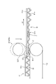
- FIG. 1 is a schematic view showing a corrugated machine as a corrugated cardboard sheet manufacturing apparatus of the present embodiment.
- the longitudinal direction of the corrugated machine is the X direction
- the horizontal direction orthogonal to the longitudinal direction (X direction) of the corrugated machine is the Y direction (width direction of the corrugated sheet)
- the longitudinal direction of the corrugated machine X direction
- the vertical direction (thickness direction of the cardboard sheet) orthogonal to the above will be described as the Z direction.
- the first sheet of the present invention corresponds to the front liner A
- the second sheet corresponds to the cores B1 and B2
- the third sheet corresponds to the back liners C1 and C2.
- the corrugated machine 10 as a corrugated cardboard sheet manufacturing apparatus first manufactures a single-sided corrugated cardboard sheet D1 by bonding a back liner C1 to a corrugated core B1 and then corrugated the inside.
- the back liner C2 is attached to the core B2 to manufacture a single-sided corrugated cardboard sheet D2.
- the back liner C2 of the single-sided corrugated cardboard sheet D2 is attached to the core B1 of the manufactured single-sided corrugated cardboard sheet D1
- the front liner A is attached to the core B2 of the single-sided corrugated board sheet D2 to form a continuous double-sided corrugated cardboard sheet E.
- a plate-shaped double-sided corrugated cardboard sheet F is manufactured by cutting the continuous double-sided corrugated cardboard sheet E to a predetermined length.
- the corrugated machine 10 can manufacture a double-sided corrugated cardboard sheet by laminating a single-sided corrugated cardboard sheet D2 or a single-sided corrugated cardboard sheet D1 and a front liner A. Further, the corrugated machine 10 can manufacture a double-sided corrugated cardboard sheet by laminating a single-sided corrugated cardboard sheet D1, a single-sided corrugated cardboard sheet D2, and a front liner A. Therefore, in the following description, the double-sided corrugated cardboard sheet and the double-sided corrugated cardboard sheet will be collectively referred to as a double-sided corrugated cardboard sheet E. Further, the plate-shaped double-sided corrugated cardboard sheet and the plate-shaped double-sided corrugated cardboard sheet will be collectively referred to as a double-sided corrugated cardboard sheet F.
- the corrugated machine 10 includes a mill roll stand 11 with a core B1, a mill roll stand 12 with a back liner C1, a single facer 13, a bridge 14, a mill roll stand 15 with a core B2, and a mill with a back liner C2.
- Roll stand 16 single facer 17, bridge 18, mill roll stand 19 of front liner A, preheater 20, glue machine 21, double facer 22, rotary shear 23, slitter scorer 24, and cutoff.
- a defective product discharging device 26, and a stacker 27 are provided.
- the mill roll stands 11 and 15 are equipped with roll paper on which cores B1 and B2 are wound in a roll shape on both sides in the X direction, and splicers 31 and 32 for splicing paper are provided between the roll papers.
- the splicers 31 and 32 put the other roll paper on one roll paper when the remaining roll paper is low. Is spliced on paper. Therefore, the cores B1 and B2 are continuously fed from the mill roll stands 11 and 15 toward the downstream side.
- the mill roll stands 12 and 16 are equipped with roll paper on which the back liners C1 and C2 are wound in a roll shape on both sides in the X direction, and splicers 33 and 34 for splicing the paper are provided between the roll papers. Be done. When the other roll paper is attached and the paper splicing is prepared while the paper is being fed from one roll paper, the splicers 33 and 34 put the other roll paper on one roll paper when the remaining roll paper is low. Is spliced on paper. Therefore, the back liners C1 and C2 are continuously fed from the mill roll stands 12 and 16 toward the downstream side.
- the cores B1 and B2 drawn out from the mill roll stands 11 and 15 and the back liners C1 and C2 drawn out from the mill roll stands 12 and 16 are preheated by preheaters (not shown), respectively.
- Each preheater has a heating roll to which steam is supplied to the inside, and the core B1 and B2 and the back liners C1 and C2 are wound around the heating roll and conveyed to raise the temperature to a predetermined temperature.
- the heated core B1 is processed into a wavy shape and then glued to the top of each step, and the heated back liner C1 is bonded to form a single-sided corrugated cardboard sheet D1.
- a pick-up conveyor 28 is provided at the outlet of the single-sided corrugated cardboard sheet D1, and the single-sided corrugated cardboard sheet D1 formed by the single facer 13 is conveyed to the bridge 14.
- the bridge 14 temporarily retains the single-sided corrugated cardboard sheet D1 in order to absorb the speed difference between the single facer 13 and the double facer 22.
- the heated core B2 is processed into a wavy shape and then glued to the top of each step, and the heated back liner C2 is bonded to form a single-sided corrugated cardboard sheet D2.
- a pick-up conveyor 29 is provided at the outlet of the single-sided corrugated cardboard sheet D2, and the single-sided corrugated cardboard sheet D2 formed by the single facer 17 is conveyed to the bridge 18.
- the bridge 18 temporarily retains the single-sided corrugated cardboard sheet D2 in order to absorb the speed difference between the single facer 17 and the double facer 22.
- the paper guide device 30 is provided at the outlets of the bridge 14 and the bridge 18.
- the paper guide device 30 adjusts the Y-direction positions of the single-sided corrugated board sheet D1 and the single-sided corrugated board sheet D2 between the bridge 14 and the bridge 18 and the double facer 22.
- the mill roll stand 19 is provided with roll paper on which the front liner A is wound in a roll shape on both sides thereof, and a splicer 35 for splicing the paper between the roll papers.
- a splicer 35 for splicing the paper between the roll papers.
- three preheating rolls 41, 42, and 43 are arranged side by side in the Z direction.
- the preheating roll 41 heats the front liner A
- the preheating roll 42 heats the single-sided corrugated cardboard sheet D2
- the preheating roll 43 heats the single-sided corrugated cardboard sheet D1.
- Each of the preheating rolls 41, 42, and 43 has a winding amount adjusting device (not shown), and steam is supplied to the inside to heat the preheating rolls 41, 42, and 43 to a predetermined temperature.
- the sheet D1 is wound to preheat it.
- the glue rolls 44 and 45 are arranged side by side in the Z direction.
- the gluing roll 44 contacts each top of the stage of the core B2 in the single-sided corrugated cardboard sheet D2 heated by the preheating roll 42 to perform gluing.
- the gluing roll 45 contacts each top of the stage of the core B1 in the single-sided corrugated cardboard sheet D1 heated by the preheating roll 43 to perform gluing.
- the single-sided corrugated cardboard sheets D1 and D2 glued by the glue machine 21 are transferred to the double facer 22 in the next step.
- the front liner A heated by the preheating roll 41 is also transferred to the double facer 22 through the glue machine 21.
- the double facer 22 has a heating section 36 on the upstream side and a cooling section 37 on the downstream side along the traveling lines of the single-sided corrugated cardboard sheets D1 and D2 and the front liner A.
- the single-sided corrugated cardboard sheets D1 and D2 and the front liner A glued by the glue machine 21 are carried in between the pressure belt and the hot plate in the heating section 36, and are cooled together in a state of being overlapped with each other. Transferred to section 37. During this transfer, the single-sided corrugated cardboard sheets D1 and D2 and the front liner A are heated while being pressurized to be bonded to each other to form a continuous double-sided corrugated cardboard sheet E, and then naturally cooled while being transported.
- the double-sided corrugated cardboard sheet E manufactured by the double facer 22 is transferred to the slitter scorer 24.
- the slitter scorer 24 cuts a wide double-sided corrugated cardboard sheet E along the X direction so as to have a predetermined width, and processes a ruled line extending in the X direction.
- the slitter scorer 24 is composed of a first slitter scorer unit 53 and a second slitter scorer unit 54 having substantially the same structure arranged along the X direction of the double-sided corrugated cardboard sheet E.
- the wide double-sided corrugated cardboard sheet E is cut by the slitter scorer 24 to form a double-sided corrugated cardboard sheet E having a predetermined width.
- the cutoff 25 cuts the double-sided corrugated cardboard sheet E cut in the X direction by the slitter scorer 24 along the Y direction to form a plate-shaped double-sided corrugated cardboard sheet F having a predetermined length.
- the defective product discharging device 26 discharges the double-sided corrugated cardboard sheet F determined to be a defective product by the defect detecting device described later from the transport line.
- the defective product discharge device 26 has a discharge conveyor and a distribution roll. When the plate-shaped double-sided corrugated cardboard sheet F determined to be defective is conveyed, the distribution roll is lowered to distribute the defective plate-shaped double-sided corrugated cardboard sheet F to the discharge conveyor and discharge the defective product.
- the stacker 27 stacks the double-sided corrugated cardboard sheets F determined to be non-defective products and discharges them to the outside of the machine as a product.
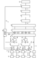
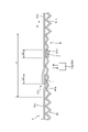
- FIG. 2 is a schematic configuration diagram showing a corrugated cardboard sheet splicing portion detecting device of the present embodiment
- FIG. 3 is a schematic configuration diagram showing a processing flow in the corrugated cardboard sheet splicing portion detecting device of the present embodiment.
- the corrugated board sheet splicing portion detecting device 60 is a sheet splicing in a double-sided corrugated board sheet E in which a front liner A, corrugated cores B1 and B2, and back liners C1 and C2 are bonded together. It detects the part.
- the corrugated cardboard sheet splicing portion detecting device 60 includes a sheet splicing portion detecting unit 61, a mark giving device 62, a mark detecting device 63, and a control device 64.
- the sheet paper splicing detection unit 61 is arranged between the sheet paper splicing position and the sheet laminating position in the sheet transport direction (one of the X directions).
- the sheet paper splicing detection unit 61 detects the sheet paper splicing portion based on the sheet shape. Specifically, the sheet paper splicing detection unit 61 detects the sheet paper splicing portion based on the sheet thickness.
- the mark giving device 51 gives a mark to the sheet paper splicing portion on the downstream side in the sheet transport direction from the sheet paper splicing detecting unit 61.
- the mark detecting device 63 detects the mark on the downstream side in the sheet transport direction from the mark applying device 62.
- the control device 64 controls the operation timing of the mark giving device 62 based on the detection result of the sheet paper splicing detection unit 61. Further, the control device 64 controls the operation timing of the defective product discharging device (sheet removing device) 26 based on the position information of the mark detected by the mark detecting device 63.
- the sheet paper splicing detection unit 61 detects the sheet paper splicing portions in the front liner A, the cores B1 and B2, and the back liners C1 and C2, respectively.
- the cores B1 and B2 are fed out from the mill roll stands 11 and 15 and conveyed to the single facers 13 and 17 through the splicers 31 and 32.
- the back liners C1 and C2 are fed out from the mill roll stands 12 and 16 and are conveyed to the single facers 13 and 17 through the splicers 33 and 34.
- the sheet paper splicing detection unit 61 is composed of five ultrasonic sensors 61a, 61b, 61c, 61d, 61e.
- Ultrasonic sensors 61a, 61b, 61c, 61d are arranged between splicers 31, 32, 33, 34 and single facers 13, 17. Further, the ultrasonic sensor 61e is arranged between the splicer 35 and the preheater 20. The ultrasonic sensors 61a, 61b, 61c, 61d, 61e output the detection result to the control device 64.
- FIG. 4 is a schematic view showing the sheet paper splicing detection unit.
- the rear end portion of the leading paper B1a and the front end portion of the trailing paper B1b are connected by a paper splicing portion B1c.
- the paper splicing portion B1c is connected so that the lower surface of the rear end portion of the leading paper B1a and the upper surface of the tip portion of the trailing paper B1b overlap each other with the double-sided tape T. Therefore, the thickness of the paper splicing portion B1c is the sum of the thickness of the leading paper B1a, the thickness of the trailing paper B1b, and the thickness of the double-sided tape T.
- the thickness of the paper splicing portion B1c is larger than the thickness of the leading paper B1a and the thickness of the trailing paper B1b.
- the ultrasonic sensor 61a has a transmission unit 61a-1 and a reception unit 61a-2.
- the transmission unit 61a-1 is arranged on the upper surface side of the core B1 to be transported, and the reception unit 61a-2 is arranged on the lower surface side of the core B1 to be transported so as to face the transmission unit 61a-1.
- the transmitting unit 61a-1 transmits ultrasonic waves toward the core B1, and the receiving unit 61a-2 receives the ultrasonic waves transmitted through the core B1. At this time, the ultrasonic waves transmitted from the transmitting unit 61a-1 are attenuated when passing through the core B1, and the attenuated ultrasonic waves are received by the receiving unit 61a-2.
- the core B1 has a thicker paper splicing portion B1c than the thickness of the leading paper B1a and the trailing paper B1b. Therefore, in the core B1, the amount of ultrasonic wave attenuation of the paper splicing portion B1c is larger than the amount of ultrasonic wave attenuation of the preceding paper B1a and the trailing paper B1b.
- the ultrasonic sensor 61a outputs the level of the ultrasonic wave received by the receiving unit 61a-2 to the control device 64.
- the control device 64 detects the paper splicing portion B1c based on the level of the ultrasonic wave input from the ultrasonic sensor 61a. That is, the level of the ultrasonic wave transmitted through the leading paper B1a and the trailing paper B1b is measured in advance, and the level of the ultrasonic wave transmitted through the paper splicing portion B1c is measured in advance.
- a threshold value (determination value) is set between the level of the ultrasonic wave transmitted through the leading paper B1a and the trailing paper B1b and the level of the ultrasonic wave transmitted through the paper splicing portion B1c. Then, the control device 64 detects the paper joint portion B1c by comparing the level of the ultrasonic wave input from the ultrasonic sensor 61a with the determination value.
- the sheet paper splicing detection unit 61 is not limited to the ultrasonic sensors 61a, 61b, 61c, 61d, and 61e.
- the sheet paper splicing detection unit 61 may be configured by a laser displacement meter. That is, the laser displacement meter is arranged on the upper surface side or the lower surface side of the core B1 to be conveyed.
- the paper splicing portion B1c has a step between the leading paper B1a and the trailing paper B1b. Therefore, the core B1 has a different distance from the laser displacement meter to the leading paper B1a and the distance from the trailing paper B1b.
- the control device 64 the time until the laser displacement meter transmits toward the preceding paper B1a and returns after reflection, and the time until the laser displacement meter transmits toward the trailing paper B1b and returns after reflection.
- the sheet step is detected, and the paper joint portion B1c is detected based on the position on this sheet step.
- the mark giving device 62 is controlled by the control device 64.
- the control device 64 By operating the mark-imparting device 62, the control device 64 imparts marks to the positions of the cores B1 and B2 and the back liners C1 and C2 detected by the sheet sheet splicing detection unit 61.
- the mark giving device 62 is composed of two crushing rollers 62a and 62b.
- the crushing rollers 62a and 62b are arranged between the single facers 13 and 17 and the bridges 14 and 18 on the downstream side in the sheet transport direction from the ultrasonic sensors 61a, 61b, 61c and 61d.
- Two crushing rollers 62a and 62b as the mark giving device 62 may be arranged between the bridges 14 and 18 and the preheater 20.
- the crushing roller 62a is rotatably arranged at a position separated by a predetermined distance from the back liner C1 constituting the single-sided corrugated cardboard sheet D1.
- the crushing roller 62a moves so as to approach the single-sided corrugated cardboard sheet D1 and crushes the core B1 of the single-sided corrugated cardboard sheet D1 to form a crushed portion as a mark.
- the crushing roller 62b is rotatably arranged at a position separated by a predetermined distance from the back liner C2 constituting the single-sided corrugated cardboard sheet D2.
- the crushing roller 62b moves so as to approach the single-sided corrugated cardboard sheet D2, and crushes the core B2 of the single-sided corrugated cardboard sheet D2 to form a crushed portion as a mark.
- the mark giving device 62 may be configured by four spray nozzles 62c, 62d, 62e, 62f instead of the two crushing rollers 62a, 62b. As shown by the alternate long and short dash line in FIG. 3, the spray nozzles 62c, 62d, 62e, 62f are the ultrasonic sensors 61a, 61b, 61c between the splicers 31, 32, 33, 34 and the single facers 13, 17. , 61d is arranged on the downstream side in the sheet transport direction.
- the spray nozzles 62c and 62d are arranged apart from the cores B1 and B2 by a predetermined distance, and can eject ink for a predetermined time. Further, the spray nozzles 62e and 62f are arranged apart from the back liners C1 and C2 by a predetermined distance, and can eject ink for a predetermined time.
- the spray nozzles 62c, 62d, 62e, and 62f give marks to the paper joints by ejecting ink toward the cores B1 and B2 and the back liners C1 and C2.
- the mark detecting device 63 detects the mark given by the mark giving device 62.
- the mark detection device 63 is composed of four mark detectors 63a, 63b, 63c, 63d.
- the mark detectors 63a, 63b, 63c, 63d are arranged between the preheater 20 and the glue machine 21.
- the mark detectors 63a and 63b are arranged so as to be separated from the surface to which the front liner A of the cores B1 and B2 of the single-sided corrugated cardboard sheets D1 and D2 is attached by a predetermined distance.
- the mark detectors 63c and 63d are arranged apart from the back liners C1 and C2 by a predetermined distance.
- the control device 64 controls the operation of the defective product discharging device 26 based on the position information of the mark detected by the mark detecting device 63.
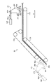
- FIG. 5 is a schematic view of the peripheral portion of the single facer showing the arrangement position of the sheet paper splicing detection unit and the mark giving device
- FIG. 6 is a schematic view showing the marking apparatus
- FIG. 7 is the arrangement position of the marking apparatus.
- FIG. 8 is a schematic view of the peripheral portion of the single facer showing a modification of the above
- FIG. 8 is a schematic diagram of the peripheral portion of the double facer showing the arrangement position of the sheet paper splicing detection unit and the mark detection device
- FIG. 9 shows the mark detection device.
- FIGS. 10 are schematic views showing the operation of the mark detection device. Since the single facer 13 and the single facer 17 have almost the same configuration, the configuration of the peripheral portion of the single facer 13 will be described, and the description of the configuration of the peripheral portion of the single facer 17 will be omitted. ..
- the stand 101 is installed at a predetermined position, and roll support arms 102a and 102b are provided on both sides in the X direction.
- the roll support arms 102a and 102b are rotatably supported by the roll papers R1 and R2 of the core B1 at the tip end portions.
- the roll papers R1 and R2 are made by winding a core B1 having a predetermined length into a roll shape.
- the roll paper R1 supported by one roll support arm 102a rotates to supply the core B1, and the roll paper R2 supported by the other roll support arm 102b stops to stop the core B1. Waiting for the paper splicing.
- the splicer 31 is arranged above the mill roll stand 11 in the Z direction.
- the splicer 31 is configured by arranging a pair of introduction rolls 104a, 104b, a pair of knives 105a, 105b, and a pair of crimping bars 106a, 106b upward in the Z direction of the header 103.
- the nip roll 107 and the acceleration roll 108 are arranged so as to face each other above the crimp bars 106a and 106b in the Z direction.
- the introduction rolls 104a and 104b, the knives 105a and 105b, and the crimp bars 106a and 106b are provided so as to be able to approach and separate from each other along the X direction.
- the nip roll 107 is provided so as to be able to approach and separate from the acceleration roll 108 along the X direction.
- the dancer roll 109 and the fixed roll 110 are arranged above the nip roll 107 and the acceleration roll 108 in the Z direction.
- a plurality (for example, three) of dancer rolls 109 are provided and can move along the horizontal direction according to the tension of the core B1. That is, the dancer roll 109 is movable between the position shown in FIG. 5 and the position close to the fixed roll 110.
- the core B1 passes between the introduction rolls 104a and 104b, between the knives 105a and 105b, and between the crimping bars 106a and 106b, and from the acceleration roll 108 to the dancer roll 109. Is conveyed via the fixed roll 110.
- the paper splicing is performed by the splicer 31
- the feeding of the core B1 from the roll paper R1 is stopped, and the core B1 from the waiting roll paper R2 is attached to the core B1 of the roll paper R1 to carry out the paper splicing. After that, the roll paper R2 is rotated to feed out the core B1.
- the core B1 is drawn out from the roll paper R2 and attached to the crimp bar 106b.
- the core B1 from the roll paper R1 By reducing the feeding speed of the core B1 from the roll paper R1 and moving the dancer roll 109 toward the fixed roll 110, consumption of the stagnant core B1 is started.
- the core B1 from the roll paper A2 is pressed against the core B1 from the roll paper R1 and adhered. It is crimped with an agent (double-sided tape).
- the knife 105a advances and cuts the core B1 from the roll paper R1.
- the dancer roll 109 moves to keep the tension of the core B1 constant and continue to release the stagnant core B1.
- the nip roll 107 comes into contact with the acceleration roll 108 to increase the rotation speed of the acceleration roll 108.
- the release of the stagnant core B1 is completed, and the dancer roll 109 starts to move and returns to the original position.
- the mill roll stand 12 (see FIG. 1) for feeding the back liner C1 and the splicer 33 for joining the back liner C1 with paper are almost the same as the mill roll stand 11 and the splicer 31.
- the single facer 13 includes a belt roll 121, a tension roll 122, a pressure belt 123, an upper roll 124, a lower roll 125, and a gluing device 126.
- the belt roll 121 can be driven and rotated by a drive device (not shown).
- the tension roll 122 is rotatably supported with a predetermined distance from the belt roll 121.
- the pressure belt 123 is an endless belt and is hung between the belt roll 121 and the tension roll 122.
- the upper roll 124 can be driven and rotated by a driving device (not shown), and the outer peripheral surface is formed in a wavy shape.
- the upper roll 124 is arranged below the pressure belt 123 in the Z direction between the belt roll 121 and the tension roll 122, and the corrugated outer peripheral surface abuts on the lower surface of the pressure belt 123 in a pressurized state.
- the lower roll 125 has an outer peripheral surface formed in a wavy shape and meshes with the outer peripheral surface of the upper roll 124 below the upper roll 124 in the Z direction.
- the belt roll 121, the tension roll 122, the upper roll 124, and the lower roll 125 are heated by circulating steam inside.
- the core B1 and the back liner C are heated via the pressure belt 123 and the upper roll 124.
- the gluing device 126 is arranged in the vicinity of the upper roll 124 in the X direction.
- the gluing device 126 has a gluing dam 127, a gluing roll 128, a meter roll 129, and a gluing blade 130.
- the glue dam 127 stores a predetermined amount of glue.
- the gluing roll 128 adheres the glue stored in the glue dam 127 to the core B1 conveyed by the upper roll 124 for gluing.
- the meter roll 129 is in contact with the outer peripheral surface of the gluing roll 128 and rotates synchronously to adjust the amount of glue adhered to the outer peripheral surface of the gluing roll 128.
- the glue scraping blade 130 comes into contact with the outer peripheral surface of the meter roll 129 to remove it from the gluing roll 128 and scrape off excess glue adhering to the outer peripheral surface of the meter roll 129.
- the single facer 13 is provided with a preheating roll 131 and an angle adjusting roll 132 for introducing the core B1 supplied from the splicer 31 between the upper roll 124 and the lower roll 125.
- the angle adjusting roll 132 adjusts the contact position where the core B1 contacts the outer peripheral surface of the preheating roll 131 by moving around the preheating roll 131.
- the single facer 13 is provided with a preheating roll 133 and a fixed roll 134 for introducing the back liner C1 supplied from the splicer 33 between the pressure belt 123 and the upper roll 124.
- the single facer 13 has preheaters 141 and 142.
- the preheater 141 preheats the back liner C1.
- the preheater 141 is arranged adjacent to the preheating roll 133.
- the preheater 141 has two preheating rolls 151 and 152 arranged in the Z direction.
- the preheating rolls 151 and 152 heat the back liner C1 by winding the back liner C1 around the preheating rolls 151 and 152.
- the preheating rolls 151 and 152 have a winding amount adjusting device (not shown), and steam is supplied to the inside to heat the preheating rolls 151 and 152 to a predetermined temperature.
- a plurality of guide rolls 153 are provided on the upstream side and the downstream side of the preheating rolls 151 and 152.
- the preheater 142 preheats the core B1.
- the preheater 142 is arranged adjacent to the preheating roll 131.
- the preheater 142 has one preheating roll 161.
- the preheating roll 161 heats the core B1 by winding the core B1 around it.
- the preheating roll 161 has a winding amount adjusting device (not shown), and steam is supplied to the inside to heat the preheating roll 161 to a predetermined temperature.
- a guide roll 162 is provided on the upstream side of the preheating roll 161.
- the single facer 13 is provided with a pick-up conveyor 28.
- the pick-up conveyor 28 guides the single-sided corrugated cardboard sheet D1 formed by the single facer 13 and supplies it to the bridge 14 (see FIG. 1).
- the pick-up conveyor 28 has a first lower belt 172, a second lower belt 173, and an upper belt 174.
- the first lower belt 172 and the second lower belt 173 are arranged obliquely upward, and the upper belt 174 is arranged along the horizontal direction.
- the first lower belt 172, the second lower belt 173, and the upper belt 174 can be driven by a drive device (not shown).
- the single-sided corrugated cardboard sheet D1 is sandwiched between the first lower belt 172, the second lower belt 173, and the upper belt 174 and conveyed.
- the back liner C1 is supplied from the splicer 33 to the single facer 13 via the preheater 141. After being wound around the preheating roll 133, the back liner C1 is transferred to the nip portion between the pressure belt 123 and the upper roll 124 together with the pressure belt 123 guided by the belt roll 121.
- the core B1 is supplied from the splicer 31 to the single facer 13 via the preheater 142. After being wound around the preheating roll 131, the core B1 is processed into a wavy shape at the meshing portion between the upper roll 124 and the lower roll 125, and is guided by the upper roll 124 to nip the pressure belt 113 and the upper roll 114. Transferred to the department.
- the core B1 is processed into a wavy shape at the meshing portion between the upper roll 124 and the lower roll 125, and then glued by the gluing device 126.
- the glue stored in the glue dam 127 adheres to the rotating glue roll 128, and the amount of glue adhered to the outer peripheral surface is adjusted by the meter roll 129.
- the core B1 processed into a wavy shape at the meshing portion between the upper roll 124 and the lower roll 125 is glued to the top of each step by coming into contact with the gluing roll 128.
- the glued core B1 is transferred to the nip portion of the pressure belt 123 and the upper roll 124, it is attached to the back liner C1 to form a single-sided corrugated cardboard sheet D1.
- an ultrasonic sensor 61a for detecting the paper splicing portion of the core B1 and an ultrasonic sensor 61c for detecting the paper splicing portion of the back liner C1 are provided.
- the ultrasonic sensor 61a is arranged between the fixed roll 110 of the splicer 31 and the guide roll 162 of the preheater 142.
- the ultrasonic sensor 61a detects a paper splicing portion of the core B1 conveyed between the fixed roll 110 of the splicer 31 and the guide roll 162 of the preheater 142.
- the arrangement position of the ultrasonic sensor 61a is not limited to this position.
- the ultrasonic sensor 61a may be arranged between the dancer roll 109 of the splicer 31 and the preheating roll 131 of the single facer 13. In this case, since the dancer roll 109 sends out the core B1 that has stayed while moving during the paper splicing, it is preferably downstream from the maximum moving position of the dancer roll 109.
- the ultrasonic sensor 61c is arranged between the guide rolls 153 of the preheater 141.
- the ultrasonic sensor 61c detects a paper splicing portion of the back liner C1 conveyed between the guide rolls 153 of the preheater 141.
- the arrangement position of the ultrasonic sensor 61c is not limited to this position.
- the ultrasonic sensor 61c may be arranged between the dancer roll 109 of the splicer 33 and the preheating roll 133 of the single facer 13. In this case, since the dancer roll 109 sends out the back liner C1 that has stayed while moving during the paper splicing, it is preferably downstream from the maximum moving position of the dancer roll 109.
- a crushing roller 62a for imparting a mark (crushed portion) to the single-sided corrugated cardboard sheet D2 is provided.
- the crushing roller 62a is arranged on the downstream side of the pick-up conveyor 28 between the single facer 13 and the bridge 14.
- the crushing roller 62a forms a crushed portion as a mark by crushing the core B1 of the single-sided corrugated cardboard sheet D formed by laminating the core B1 processed in a wavy shape by the single facer 13 and the back liner C1. do.
- the arrangement positions of the ultrasonic sensors 61a and 61c as the sheet paper splicing detection unit 61 arranged in the peripheral portion of the single facer 13 and the crushing roller 62a as the mark giving device 62 have been described.
- the arrangement positions of the ultrasonic sensors 61b and 61d as the sheet paper splicing detection unit 61 arranged in the peripheral portion of the single facer 17 and the crushing roller 62b as the mark giving device 62 are also the same.
- the mark giving device 62 is arranged on the downstream side in the transport direction of the pick-up conveyor 28.
- the pick-up conveyor 28 has a first lower belt 172, a second lower belt 173, and an upper belt 174.
- the mark giving device 62 gives a mark to the corrugated core B1 in the single-sided corrugated board sheet D1 conveyed by each belt 172, 173, 174.
- the mark giving device 62 gives a mark by crushing the corrugated core B1 in the single-sided corrugated cardboard sheet D1.
- the mark giving device 62 has a rotating link 204, a crushing roller 62a, and an air cylinder (or hydraulic cylinder) 206.
- the rotation link 204 is rotatably supported by a frame (not shown) by a mounting member 207.
- the crushing roller 62a is rotatably supported by a support member 208 under the rotation link 204.
- the air cylinder 206 is mounted on a frame (not shown), and the tip of the drive rod 206a is connected to the upper part of the rotation link 204 by a connecting member 209.
- the crushing roller 62a is arranged above the guide roll that supports the second lower belt 173 with a predetermined gap.
- the predetermined gap is a gap in which the single-sided corrugated cardboard sheet D1 supported by the guide roll can be conveyed without contacting the crushing roller 62a.
- the control device 64 operates the mark giving device 62 based on the detection result of the sheet paper splicing detection unit 61. That is, in the mark giving device 62, the drive rod 206a is extended by the operation of the air cylinder 206, and the rotation link 204 is rotated in the clockwise direction in FIG. Then, the crushing roller 62a moves so as to approach the single-sided corrugated cardboard sheet D1 guided by the second lower belt 173, and the core B1 in the single-sided corrugated cardboard sheet D1 is crushed to give a mark.
- the mark detection device 63 (see FIG.
- the mark giving device 62 may be arranged on the upstream side in the transport direction of the pick-up conveyor 28.
- the crushing roller 62a is arranged above the guide roll that supports the first lower belt 172 with a predetermined gap.
- the predetermined gap is a gap in which the single-sided corrugated cardboard sheet D1 supported by the guide roll can be conveyed without contacting the crushing roller 62a.
- the mark giving device 62 gives a mark to the corrugated core B1 in the single-sided corrugated board sheet D1 before being conveyed by each belt 172, 173, 174.
- the mark giving device 62 is provided with the crushing rollers 62a and 62b, but the crushing rollers 62a and 62b may be driveable rollers or rotating rollers that can be carried around. Further, the present invention is not limited to the crushing rollers 62a and 62b, and may be a crushing block, a crushing plate, or the like, and is not limited to the shape thereof. Further, although the crushing rollers 62a and 62b are rotatably supported by the rotating link 204, they may be slidable. Further, a drive motor may be used instead of the air cylinder (or hydraulic cylinder) 206.
- FIG. 7 is a schematic view of the peripheral portion of the single facer showing a modified example of the arrangement position of the mark giving device.
- the spray nozzle 62c is arranged between the preheating roll 161 of the preheater 142 and the preheating roll 131 of the single facer 13.
- the spray nozzle 62c sprays ink onto the surface of the core B1 to which the front liner A is attached, which is conveyed between the preheating roll 161 of the preheater 142 and the preheating roll 131 of the single facer 13, to form a paper splicing portion. Is marked with.
- the arrangement position of the spray nozzle 62c is not limited to this position.
- the spray nozzle 62c may be arranged between the dancer roll 109 of the splicer 31 and the preheating roll 131 of the single facer 13 on the downstream side in the sheet transport direction from the ultrasonic sensor 61a.
- the spray nozzle 62e is arranged between the guide roll 153 of the preheater 141 and the preheating roll 133 of the single facer 13.
- the spray nozzle 62e sprays ink onto the surface of the back liner C1 that is conveyed between the guide roll 153 of the preheater 141 and the preheating roll 133 of the single facer 13 to which the core B1 cannot be attached, thereby splicing the paper. Add a mark to the part.
- the arrangement position of the spray nozzle 62e is not limited to this position.
- the spray nozzle 62e may be arranged between the dancer roll 109 of the splicer 33 and the preheating roll 133 of the single facer 13 on the downstream side in the sheet transport direction from the ultrasonic sensor 61c.
- the spray nozzle 62c constituting the mark applying device 62 imparts a mark to the core B1 constituting the single-sided corrugated cardboard sheet D1.
- the spray nozzle 62e gives a mark to the back liner C1 constituting the single-sided corrugated cardboard sheet D1. That is, the spray nozzles 62c and 62e give a mark to the single-sided corrugated cardboard sheet D1 formed by bonding the core B1 and the back liner C1 with the single facer 13.
- the spray nozzles 62c and 62e are arranged at positions facing each other across the transport path of the single-sided corrugated cardboard sheet D1 on the outlet side of the single facer 13.
- the mark giving device 62 may be any as long as it gives a mark to the single-sided corrugated cardboard sheet D1, and is not limited to this arrangement position.
- the mark giving device 62 may be arranged between the single facer 13 and the double facer 22. Further, only one of the spray nozzles 62c and 62e may be arranged.
- the control device 64 sprays the core B1 at positions corresponding to the paper splicing portion of the core B1 and the paper splicing portion of the back liner C1. Operate the nozzle 62c. In the case of only the spray nozzle 62e, the opposite is true. As a result, the number of marking devices 62 can be reduced.
- the mark is given to either the core or the back liner, so that the number of mark detection devices 63 can be reduced.
- the mark detector 63a may be arranged.
- the mark detector 63c may be arranged.
- the arrangement positions of the spray nozzles 62c and 62e as the mark giving device 62 have been described. Although not shown, the arrangement positions of the spray nozzles 62d and 62f as the mark giving device 62 arranged in the peripheral portion of the single facer 17 are also the same.
- the paper guide device 30 is provided at the outlets of the bridge 14 and the bridge 18, respectively.
- the paper guide device 30 includes a twisting roller (not shown), and the twisting roller contacts the upper surfaces of the single-sided corrugated board sheet D1 and the single-sided corrugated board sheet D2, that is, the back liner C1 and the back liner C2.
- a moving device not shown
- the twisting roller is tilted in the X direction, and the single-sided corrugated cardboard sheet D1 and the single-sided corrugated cardboard sheet D2 are guided to the twisting roller.
- the positions of the single-sided corrugated cardboard sheet D1 and the single-sided corrugated cardboard sheet D2 in the Y direction are adjusted, and meandering or biased transport in either the Y direction is suppressed.
- the preheater 20 is configured by rotatably supporting preheating rolls 41, 42, and 43 on a frame 181.
- the preheating rolls 41, 42, and 43 heat the front liner A, the single-sided corrugated cardboard sheet D1, and the single-sided corrugated cardboard sheet D2.
- the guide rolls 182a, 182b, 182c and the winding angle adjusting rolls 183a, 183b, 183c are arranged on the upstream side in the transport direction, respectively, and the guide rolls 184a, 184b, 184c are arranged on the downstream side, respectively. Be placed.
- the winding angle adjusting rolls 183a, 183b, and 183c move in the circumferential direction of the preheating rolls 41, 42, and 43 to adjust the winding angles of the front liner A, the single-sided corrugated cardboard sheet D1, and the single-sided corrugated cardboard sheet D2 for preheating. Adjust the temperature.
- the glue machine 21 is configured by rotatably supporting the glue rolls 44 and 45 on the frame 185.
- Each of the gluing rolls 44 and 45 applies the glue of the glue dams 186a and 186b to the cores B1 and B2 of the single-sided corrugated cardboard sheet D1 and the single-sided corrugated cardboard sheet D2, respectively.
- the gluing rolls 44 and 45 are arranged so that the meter rolls 187a and 187b for adjusting the amount of adhesive adhesion are in contact with each other, and the rider rolls 188a and 188b are arranged so as to face each other.
- the preheaters 190 and 191 are rotatably supported by the frame 189.
- the front liner A is guided to the double facer 22 via the preheater 190, and the single-sided corrugated cardboard sheets D1 and D2 are guided to the double facer 22 via the preheater 191.
- an ultrasonic sensor 61e for detecting the paper splicing portion of the front liner A is provided.
- the ultrasonic sensor 61e is arranged between the fixed roll 111 of the splicer 35 and the guide roll 182a of the preheater 20.
- the ultrasonic sensor 61e detects a paper splicing portion of the front liner A that is conveyed between the fixed roll 111 of the splicer 35 and the guide roll 182a of the preheater 20.
- the arrangement position of the ultrasonic sensor 61e is not limited to this position.
- the ultrasonic sensor 61e may be arranged between the dancer roll 109 of the splicer 35 and the preheater 190 of the double facer 22. In this case, since the dancer roll 109 sends out the front liner A that has stayed while moving during the paper splicing, it is preferable that the dancer roll 109 is downstream from the maximum moving position of the dancer roll 109.
- mark detectors 63a and 63b for detecting the marks of the single-sided corrugated cardboard sheets D1 and D2 are provided.
- the mark detectors 63a and 63b are arranged between the paper guide device 30 and the gluing rolls 44 and 45 of the glue machine 21. More specifically, it is arranged between the preheating rolls 42 and 43 of the preheater 20 and the gluing rolls 44 and 45 of the glue machine 21.
- the mark detectors 63a and 63b detect marks on the single-sided corrugated cardboard sheets D1 and D2 conveyed between the paper guide device 30 and the gluing rolls 44 and 45 of the glue machine 21.
- the marks of the single-sided corrugated cardboard sheets D1 and D2 conveyed between the preheating rolls 42 and 43 of the preheater 20 and the gluing rolls 44 and 45 of the glue machine 21 are detected.
- the single-sided corrugated board sheet D1 and the single-sided corrugated board sheet D2 are adjusted to the Y-direction position by the paper guide device 30, and the meandering and the biased transport in either the Y-direction are suppressed. Therefore, the mark detector 63a, 63b can detect the paper splicing portion with high accuracy.
- the mark detectors 63a and 63b are arranged at positions facing the guide rolls 184c and 184b. Since the single-sided corrugated board sheet D1 and the single-sided corrugated board sheet D2 are in contact with the guide rolls 184c and 184b, the swing during transportation is suppressed, so that the mark detectors 63a and 63b detect the paper joint with high accuracy. be able to.
- the arrangement position of the mark detectors 63a and 63b is not limited to this position.
- the mark detectors 63a and 63b may be arranged between the bridges 14 and 18 and the double facer 22 on the downstream side in the sheet transport direction from the mark applying device 62 (crushing rollers 62a and 62b).
- the control device 64 includes a front liner A, a core B1, B2, and a back liner detected by a sheet paper splicing detection unit 61 (ultrasonic sensors 61a, 61b, 61c, 61d, 61e).
- the positions of the paper joints of C1 and C2 are input.
- the control device 64 determines the time when the sheet splicing detection unit 61 detects the paper splicing portions of the cores B1 and B2 and the back liners C1 and C2, and the transport speeds of the cores B1 and B2 and the back liners C1 and C2.
- the control device 64 operates the crushing rollers 62a and 62b for a predetermined time when the paper splicing portions of the cores B1 and B2 and the back liners C1 and C2 reach the mark applying device 62.
- the operating time of the crushing rollers 62a and 62b is adjusted according to the transport speeds of the cores B1 and B2 and the back liners C1 and C2. That is, the optimum shape of the mark formed on the single-sided corrugated cardboard sheets D1 and D2 is set according to the performance of the mark detection device 63, and the crushing roller 62a is set so that the mark formed on the single-sided corrugated cardboard sheets D1 and D2 has the optimum shape. , 62b adjust the operating time.
- the operating times of the crushing rollers 62a and 62b are shortened, and the transport speeds of the cores B1 and B2 and the back liners C1 and C2 are slow. If so, the operating time of the crushing rollers 62a and 62b is lengthened.
- control device 64 controls the operation timing of the defective product discharging device 26 based on the position information of the mark detected by the mark detecting device 63 (mark detectors 63a and 63b). Further, the control device 64 controls the operation timing of the defective product discharging device 26 based on the position information of the paper splicing portion of the table liner A detected by the sheet splicing detection unit 61 (ultrasonic sensor 61e). The control device 64 operates the defective product discharging device 26 at a predetermined timing to remove the double-sided corrugated cardboard sheet F having the paper splicing portion from the transport line.
- the control device 64 determines the length of the mark in the transport direction on the single-sided corrugated cardboard sheets D1 and D2 based on the transport speed of the single-sided corrugated cardboard sheets D1 and D2 and the operating time of the crushing rollers 62a and 62b by the mark-imparting device 62. It is possible to estimate the positional relationship between the paper joint and the mark. Further, in the control device 64, the transport distance of the double-sided corrugated cardboard sheet E (F) from the mark detection device 63 to the defective product discharge device 26 is input in advance, and the mark detection device 63 detects the mark and outputs a detection signal. The time from the input until the mark reaches the defective product discharging device 26 is calculated.
- the control device 64 identifies the double-sided corrugated cardboard sheet F on which the mark is formed based on the length of the mark detected by the mark detection device 63.
- the control device 64 operates the defective product discharging device 26 at the timing when the double-sided corrugated cardboard sheet F on which the mark is formed arrives, and removes the double-sided corrugated cardboard sheet F having the mark (paper joint) from the transport line. Further, the control device 64 specifies the double-sided corrugated cardboard sheet F on which the paper splicing portion is formed, based on the length of the paper splicing portion of the front liner A detected by the sheet splicing detection unit 61 (ultrasonic sensor 61e). ..
- the control device 64 operates the defective product discharging device 26 at the timing when the double-sided corrugated cardboard sheet F on which the paper splicing portion is formed arrives, and removes the double-sided corrugated cardboard sheet F having the paper splicing portion from the transport line.
- the two mark detectors 63a and 63b are applied to the mark detection device 63.
- the spray nozzles 62c, 62d, 62e, 62f are applied as the mark giving device 62
- the four mark detectors 63a, 63b, 63c, 63d are applied to the mark detection device 63.
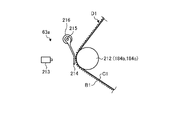
- the mark detector 63a as the mark detection device 63 when the crushing roller 62a is applied as the mark giving device 62 is applied to the core B1 of the single-sided corrugated cardboard sheet D1 conveyed by the guide roll 212. Detects the marked mark.
- the mark detector 63a is arranged together with the guide roll 212 at a desired location between the preheater 20 and the glue machine 21 (both see FIG. 8), for example.
- the mark detector 63a detects the crushed portion of the core B1 in the single-sided corrugated cardboard sheet D1 as a mark.
- the mark detector 63a has a position detector 213 and a detection lever 214.
- the position detector 213 is, for example, a laser displacement meter, and can detect the position of the detection lever 214.
- the base end of the detection lever 214 is rotatably supported by a frame (not shown) by a mounting member 215.
- the detection lever 214 is biased and supported in the counterclockwise direction in FIG. 9 by the spring member 216 around the mounting member 215.
- the tip of the detection lever 214 comes into contact with the core B1 of the single-sided corrugated cardboard sheet D1 due to the urging force of the spring member 216.
- the single-sided corrugated cardboard sheet D1 is guided and conveyed by the guide roll 212 (guide rolls 184b, 184c).
- the position detector 213 detects the position of the tip of the detection lever 214. At this time, if the core B1 of the single-sided corrugated cardboard sheet D1 is not crushed, the tip of the detection lever 214 is in contact with the top of the core B1 of the single-sided corrugated cardboard sheet D1. The position detector 213 detects the position of the tip of the detection lever 214 in contact with the top of the core B1. On the other hand, as shown in FIG.
- the tip of the detection lever 214 is in contact with the crushed portion of the core B1 of the single-sided corrugated cardboard sheet D1.
- the position detector 213 detects the position of the tip of the detection lever 214 in contact with the collapsed portion of the core B1.
- the control device 64 detects the mark based on the position of the tip of the detection lever 214 detected by the position detector 213. That is, when the position detector 213 detects the tip of the detection lever 214 in contact with the collapsed portion of the core B1, the detection distance becomes long. When the detection distance exceeds a preset determination distance, the control device 64 detects the crushed portion as a mark.
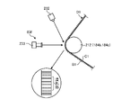
- FIG. 11 is a schematic view showing a first modification of the mark detection device
- FIG. 12 is a schematic view showing a second modification of the mark detection device.
- the mark detector 63e detects the mark given to the core B1 in the single-sided corrugated cardboard sheet D1 conveyed by the guide roll 212.
- the mark detector 63e detects the crushed portion of the core B1 in the single-sided corrugated cardboard sheet D1 as a mark.
- the mark detector 63e has an irradiation device 222 and a light receiving device 223.
- the irradiation device 222 irradiates, for example, a laser beam having a predetermined width.
- the irradiation device 222 irradiates the laser beam toward the tangential direction of the single-sided corrugated cardboard sheet D1 guided by the guide roll 212.
- the irradiation device 222 irradiates the laser beam toward the core B1 of the single-sided corrugated cardboard sheet D1.
- the light receiving device 223 receives the laser light emitted by the irradiating device 222.
- the light receiving device 223 is arranged so as to face the irradiation destination of the laser beam emitted from the irradiation device 222.
- the light receiving device 223 receives the laser light that is irradiated from the irradiation device 222 and is not blocked by the core B1 of the single-sided corrugated cardboard sheet D1.
- the single-sided corrugated cardboard sheet D1 is guided and conveyed by the guide roll 212 (guide rolls 184b, 184c).
- the irradiation device 222 irradiates the laser beam toward the core B1 of the single-sided corrugated cardboard sheet D1 guided by the guide roll 212.
- the light receiving device 223 receives the laser beam whose width is reduced by being blocked by the core B1.
- the core B1 of the single-sided corrugated cardboard sheet D1 is crushed, the amount of the laser beam blocked by the core B1 decreases.
- the light receiving device 223 receives the laser light whose width is hardly reduced without being blocked by the core B1.
- the control device 64 detects the mark based on the width of the laser beam received by the light receiving device 223. That is, when the width of the laser beam received by the light receiving device 223 exceeds a preset determination value, the crushed portion is detected as a mark.
- the mark detector 63f detects the mark given to the core B1 in the single-sided corrugated cardboard sheet D1 conveyed by the guide roll 212.
- the mark detector 63f detects the crushed portion of the core B1 in the single-sided corrugated cardboard sheet D1 as a mark.
- the mark detector 63f has an irradiation device 232 and an image pickup device 233.
- the irradiation device 232 irradiates, for example, light having a predetermined width.
- the irradiation device 232 irradiates light toward the core B1 of the single-sided corrugated cardboard sheet D1 guided by the guide roll 212.
- the image pickup apparatus 233 images the light irradiation portion of the core B1.
- the single-sided corrugated cardboard sheet D1 is guided and conveyed by the guide roll 212 (guide rolls 184b, 184c).
- the irradiation device 232 irradiates light toward the core B1 of the single-sided corrugated cardboard sheet D1 guided by the guide roll 212.
- the image pickup apparatus 233 images the light irradiation portion in the core B1.
- the control device 64 defines a bright portion and a dark portion along the transport direction of the single-sided corrugated cardboard sheet D1 based on the captured image captured by the image pickup device 233, and the length and the dark portion of the bright portion. At least one of the lengths of is compared with a preset determination value.
- the length of the dark portion is longer than the determination value.
- the length of the dark portion is shorter than the determination value. That is, when the length of the bright part or the dark part imaged by the image pickup apparatus 233 is shorter than the determination value, the crushed part is detected as a mark.
- the lengths of the bright part and the dark part maintain a constant ratio with the transportation of the single-sided corrugated cardboard sheet D1.
- the ratio of the lengths of the bright portion and the dark portion changes. That is, the crushed portion in which the ratio of the lengths of the bright portion and the dark portion imaged by the image pickup apparatus 233 is changed is detected as a mark.
- FIG. 13 is a schematic view showing a method of joining sheets
- FIG. 14 is a schematic view showing a method of assigning marks to a sheet
- FIG. 15 is a schematic view showing a method of detecting marks on a sheet.
- the operation of the paper splicing portion detecting device 60 for the corrugated cardboard sheet will be described.
- the cores B1 and B2 are fed out, and when one roll paper is reduced, the other roll paper is rotated.
- the cores B1 and B2 are fed out, the splicers 31 and 32 perform paper splicing, and the cores B1 and B2 are continuously fed out from the mill roll stands 11 and 15.
- the mill roll stands 12 and 16 when one roll paper rotates, the back liners C1 and C2 are fed out, and when one roll paper decreases, the other roll paper starts rotating, so that the back liner C1 , C2 is fed, paper splicing is performed by the splicers 33 and 34, and the back liners C1 and C2 are continuously fed from the mill roll stands 12 and 6.
- the mill roll stand 19 when one roll paper rotates, the front liner A is fed out, and when one roll paper decreases, the other roll paper starts rotating to feed out the front liner A. Paper splicing is performed by the splicer 35, and the front liner A is continuously drawn out from the mill roll stand 19.
- the leading paper B1a of the core B1 travels along the transport direction X1 and the trailing paper B1b travels at the same speed along the transport direction X2.
- the double-sided tape T as an adhesive is attached to the surface of the trailing paper B1b on the side facing the leading paper B1a at the cut end portion.
- the crimping bars 106a and 106b are brought close to each other at a predetermined timing, and the leading paper B1a and the trailing paper B1b are pressed against each other.
- the double-sided tape T of the trailing paper B1b is crimped to the sticking portion T1 of the leading paper B1a, and the trailing paper B1b is connected to the leading paper B1a.
- the paper splicing portion B1c is formed.
- the front liner A, the core B2, and the back liners C1 and C2 are also subjected to the paper splicing work in the same manner.
- the sheet paper splicing detection unit 61 detects the paper splicing portion B1c (see FIG. 14) of the core B1.
- the front liner A and the back liners C1 and C2 also detect the paper joint portion in the same manner.
- the cores B1 and B2 are processed into a wavy shape and then glued to the top of each step, and are bonded to the back liners C1 and C2 by the single facers 13 and 17, and are bonded to the back liners C1 and C2. D2 is formed. Then, as shown in FIGS.
- the mark giving device 62 gives the mark M to the paper joints B1c and C1c of the single-sided corrugated board sheet D1 by moving the crushing roller 62a. That is, when the single-sided corrugated cardboard sheet D1 travels along the transport direction X1, the crushing roller 62a determines the crushing roller 62a from a predetermined time before the paper splicing portion B1c arrives to a predetermined time after the paper splicing portion C1c passes. Move over time and crush.
- the single-sided corrugated cardboard sheet D2 is also similarly marked with the mark M at the paper joint.
- the mark detection device 63 detects the marks M attached to the single-sided corrugated cardboard sheets D1 and D2. That is, as shown in FIGS. 3 and 15, the mark detector 63a (63b) detects the mark M attached to the traveling single-sided corrugated cardboard sheet D1 (D2).
- the front liner A and the single-sided corrugated cardboard sheet D1 (D2) are bonded to each other by the double facer 22 to form a double-sided corrugated cardboard sheet E, which is cut to a predetermined width by the slitter scorer 24 and cut to a predetermined length by the cutoff 25 to form a double-sided corrugated cardboard. It becomes the sheet F.
- the control device 64 operates the defective product discharging device 26 based on the position information of each mark M of the core B1 and B2 and the back liners C1 and C2 detected by the mark detecting device 63. Control the timing. That is, the control device 64 calculates the time for each mark M of the core B1 and B2 and the back liners C1 and C2 to reach the defective product discharging device 26, and at the time when each mark M reaches the defective product discharging device 26.
- the defective product discharging device 26 is operated to remove the double-sided corrugated cardboard sheet F having the mark M (paper splicing portion) from the transport line.
- control device 64 controls the operation timing of the defective product discharging device 26 based on the position information of the paper splicing portion of the table liner A detected by the sheet splicing detecting unit 61. That is, the control device 64 calculates the time for the paper splicing portion of the front liner A to reach the defective product discharging device 26, and operates the defective product discharging device 26 at the time when the paper splicing portion reaches the defective product discharging device 26. , The double-sided corrugated cardboard sheet F having the paper splicing portion B1c is removed from the transport line.
- the control device 64 determines that the double-sided corrugated cardboard sheet F having the length region L1 including the mark M including the length region L2 where the paper splicing portion is present is a defective product, and operates the defective product discharging device 26 to operate the transport line. Remove from.
- the control device 64 includes a bridge retention amount measuring unit 70.
- a detection signal is input to the bridge retention amount measuring unit 70 when the sheet paper splicing detection unit 61 detects the paper splicing portions of the cores B1 and B2 and the back liners C1 and C2. Further, the bridge retention amount measuring unit 70 is input with a detection signal in which the mark detection device 63 detects the mark M.
- the bridge retention amount measuring unit 70 is the time from the timing when the detection signal of the paper splicing portion is input to the timing when the detection signal of the mark M is input, and the production of the single-sided corrugated cardboard sheets D1 and D2 of the single facers 13 and 17. Based on the speed, the length of the bridge retention amount of the single-sided corrugated board sheets D1 and D2 from the sheet paper splicing detection unit 61 to the mark detection device 63 can be calculated.
- the control device 64 controls the paper splicing timing of the front liner A based on the bridge retention amount of the single-sided corrugated cardboard sheets D1 and D2.
- the types of the core B1 and B2, the back liners C1 and C2, and the front liner A are changed.
- the paper joints existing in the single-sided corrugated board sheets D1 and D2 (the paper joints of the cores B1 and B2 and the paper joints of the back liners C1 and C2). Calculates the timing of arrival at the double facer 22.
- the paper joint portion of the front liner A is present on the single-sided corrugated cardboard sheets D1 and D2 based on the timing at which the paper joint portion existing on the single-sided corrugated cardboard sheets D1 and D2 arrives at the double facer 22.
- the paper splicing timing of the front liner A is controlled so as to match the portion in the transport direction.
- FIG. 16 is a schematic view showing a modified example of a method of assigning a mark to a sheet
- FIG. 17 is a schematic diagram showing a modified example of a method of detecting a mark on a sheet.
- the sheet splicing detection unit 61 detects the paper splicing portion B1c of the core B1.
- the core B2, the front liner A, and the back liners C1 and C2 also detect the paper splicing portion in the same manner.
- the spray nozzle 62c of the mark giving device 62 gives the mark M to the paper splicing portion B1c of the core B1.
- the spray nozzle 62c ejects ink for a predetermined time from a predetermined time before the paper splicing portion B1c arrives to a predetermined time after the paper splicing portion B1c passes. do.
- the core B2 and the back liners C1 and C2 are also similarly marked with the mark M on the paper joint.
- the cores B1 and B2 are processed into a wavy shape and then glued to the top of each step, and are bonded to the back liners C1 and C2 by the single facers 13 and 17, to form single-sided corrugated cardboard sheets D1 and D2.
- the mark detection device 63 detects the mark M attached to the single-sided corrugated cardboard sheets D1 and D2. In this case, since the mark detection device 63 detects the mark M given by the spray nozzles 62c, 62e (62d, 62f), the mark detectors 63a, 63c (63b, 63d) photograph the mark M, for example.
- the mark detectors 63a, 63c (63b, 63d)
- the mark M provided by the spray nozzles 62c, 62e (62d, 62f) to the traveling single-sided corrugated cardboard sheet D1 (D2).
- the mark detector 63a detects the mark M attached to the core B1 of the traveling single-sided corrugated cardboard sheet D1
- the mark detector 63c detects the mark attached to the back liner C1 of the traveling single-sided corrugated cardboard sheet D1. Detect M.
- the front liner A and the single-sided corrugated cardboard sheet D1 (D2) are bonded to each other by the double facer 22 to form a double-sided corrugated cardboard sheet E, which is cut to a predetermined width by the slitter scorer 24 and cut to a predetermined length by the cutoff 25 to form a double-sided corrugated cardboard. It becomes the sheet F.
- the paper splicing portion detecting device for the corrugated cardboard sheet according to the first aspect is arranged between the sheet splicing position and the sheet laminating position in the sheet transport direction, and is arranged between the front liner (first sheet) A and the core (second sheet).
- Sheet) B1 and B2 and back liners (third sheet) C1 and C2 are used to detect the sheet splicing part 61, and the sheet splicing detection part 61 on the downstream side in the sheet transport direction.
- a mark applying device 62 for imparting a mark to the sheet paper joint portion and a mark detecting device 63 for detecting the mark on the downstream side in the sheet transport direction from the mark applying device 62 are provided.
- the sheet splicing detecting portion 61 detects the sheet splicing portion based on the sheet thickness. As a result, the paper joints of the front liner A, the cores B1 and B2, and the back liners C1 and C2 can be detected with high accuracy.
- the sheet splicing detection unit 61 includes dancer rolls 109 of splicers (sheet splicing devices) 31, 32, 33, 34, 35 and single-sided corrugated board sheet D1, It is arranged between the preheating rolls 131 and 133 of the single facers (sheet bonding devices) 13 and 17 forming D2.
- the cores B1 and B2 and the back liners C1 and C2 to which the dancer roll 109 and the preheating rolls 131 and 133 are conveyed hardly change in the sheet thickness direction, the sheet width direction, and the sheet transfer angle, and the sheet There is almost no change in the distance between the paper splicing detection unit 61 and the cores B1 and B2 and the back liners C1 and C2, and the paper splicing portion can be detected with high accuracy. Further, since the cores B1 and B2 and the back liners C1 and C2 before pasting have almost no expansion and contraction, the paper joint portion can be detected with high accuracy.
- the mark applying device 62 includes preheating rolls 131, 133, upper rolls 124 and lower rolls of the single facers 13 and 17 forming the single-sided corrugated board sheets D1 and D2. It is placed between 125 and 125. As a result, the core B1 and B2 and the back liners C1 and C2 can be appropriately marked.
- the mark applying device 62 is arranged on the downstream side in the sheet transport direction from the single facers 13 and 17 forming the single-sided corrugated board sheets D1 and D2. As a result, the number of mark-imparting devices 62 can be reduced, and the devices can be simplified.
- the mark detecting device 63 is arranged on the downstream side in the transport direction from the bridges 14 and 18 for retaining the single-sided corrugated board sheets D1 and D2.
- the core B1 and B2 and the back liners C1 and C2 can be marked with high accuracy.
- the corrugated cardboard sheet manufacturing apparatus includes splicers 31, 32, 33, 34, 35 for joining the leading sheet and the trailing sheet in the front liner A, the cores B1 and B2, and the back liners C1 and C2.
- Single facers 13 and 17 for manufacturing single-sided corrugated board sheets D by bonding back liners C1 and C2 to corrugated cores B1 and B2, and single-sided corrugated board sheets D1 and 17 manufactured by single facers 13 and 17.
- a double facer 22 that manufactures a double-sided corrugated board sheet E by laminating a front liner A on the core B1 and B2 sides of D2, a paper splicing portion detecting device 60 for the corrugated board sheet, and a single-sided corrugated board sheet D1 and D2 based on the paper splicing portion.
- a bridge retention amount measuring unit 70 for measuring the retention amount of the corrugated cardboard is provided. As a result, the retention amount of the single-sided corrugated cardboard sheets D1 and D2 can be measured with high accuracy.
- the mark-imparting device 62 is a crushing roller or a spray nozzle, but the present invention is not limited to this configuration, and for example, an inkjet head, a coating roller, a coating brush, a stamp, a moisture-imparting device, or the like. May be.
- the mark detection device 63 detects the moisture in the front liners A, the cores B1 and B2, the back liners C1 and C2, and the single-sided corrugated cardboard sheets D1 and D2. May be detected with.
Abstract
Description
図1は、本実施形態の段ボールシートの製造装置としてのコルゲートマシンを表す概略図である。なお、以下の説明では、コルゲートマシンの長手方向をX方向、コルゲートマシンの長手方向(X方向)に直交する水平方向をY方向(段ボールシートの幅方向)、コルゲートマシンの長手方向(X方向)に直交する鉛直方向(段ボールシートの厚さ方向)をZ方向として説明する。また、本発明の第1シートは、表ライナAに相当し、第2シートは、中芯B1,B2に相当し、第3シートは、裏ライナC1,C2に相当する。 [Corrugated machine]
FIG. 1 is a schematic view showing a corrugated machine as a corrugated cardboard sheet manufacturing apparatus of the present embodiment. In the following description, the longitudinal direction of the corrugated machine is the X direction, the horizontal direction orthogonal to the longitudinal direction (X direction) of the corrugated machine is the Y direction (width direction of the corrugated sheet), and the longitudinal direction of the corrugated machine (X direction). The vertical direction (thickness direction of the cardboard sheet) orthogonal to the above will be described as the Z direction. Further, the first sheet of the present invention corresponds to the front liner A, the second sheet corresponds to the cores B1 and B2, and the third sheet corresponds to the back liners C1 and C2.
ここで、本実施形態の段ボールシートの紙継ぎ部検出装置について説明する。図2は、本実施形態の段ボールシートの紙継ぎ部検出装置を表す概略構成図、図3は、本実施形態の段ボールシートの紙継ぎ部検出装置における処理の流れを表す概略構成図である。 [Outline configuration of paper joint detection device]
Here, the paper splicing portion detecting device for the corrugated cardboard sheet of the present embodiment will be described. FIG. 2 is a schematic configuration diagram showing a corrugated cardboard sheet splicing portion detecting device of the present embodiment, and FIG. 3 is a schematic configuration diagram showing a processing flow in the corrugated cardboard sheet splicing portion detecting device of the present embodiment.
以下、シート紙継ぎ検出部61とマーク付与装置62とマーク検出装置63の具体的な配置位置について説明する。図5は、シート紙継ぎ検出部およびマーク付与装置の配置位置を表すシングルフェーサの周辺部の概略図、図6は、マーク付与装置を表す概略図、図7は、マーク付与装置の配置位置の変形例を表すシングルフェーサの周辺部の概略図、図8は、シート紙継ぎ検出部およびマーク検出装置の配置位置を表すダブルフェーサの周辺部の概略図、図9は、マーク検出装置を表す概略図、図10は、マーク検出装置の作用を表す概略図である。なお、シングルフェーサ13とシングルフェーサ17は、ほぼ同様の構成であることから、シングルフェーサ13の周辺部の構成について説明し、シングルフェーサ17の周辺部の構成についての説明は省略する。 [Specific configuration of paper joint detection device]
Hereinafter, specific arrangement positions of the sheet paper
図13は、シートの紙継ぎ方法を表す概略図、図14は、シートに対するマークの付与方法を表す概略図、図15は、シートにおけるマークの検出方法を表す概略図である。 [Operation of corrugated cardboard sheet joint detection device]
13 is a schematic view showing a method of joining sheets, FIG. 14 is a schematic view showing a method of assigning marks to a sheet, and FIG. 15 is a schematic view showing a method of detecting marks on a sheet.
第1の態様に係る段ボールシートの紙継ぎ部検出装置は、シート搬送方向におけるシート紙継ぎ位置とシート貼り合わせ位置との間に配置されて表ライナ(第1シート)Aと中芯(第2シート)B1,B2と裏ライナ(第3シート)C1,C2の形状に基づいてシート紙継ぎ部を検出するシート紙継ぎ検出部61と、シート紙継ぎ検出部61よりシート搬送方向の下流側でシート紙継ぎ部にマークを付与するマーク付与装置62と、マーク付与装置62よりシート搬送方向の下流側でマークを検出するマーク検出装置63とを備える。 [Action and effect of this embodiment]
The paper splicing portion detecting device for the corrugated cardboard sheet according to the first aspect is arranged between the sheet splicing position and the sheet laminating position in the sheet transport direction, and is arranged between the front liner (first sheet) A and the core (second sheet). Sheet) B1 and B2 and back liners (third sheet) C1 and C2 are used to detect the
11,12,15,16,19 ミルロールスタンド
13,17 シングルフェーサ(シート貼り合わせ装置)
14,18 ブリッジ
20 プレヒータ
21 グルーマシン
22 ダブルフェーサ(シート貼り合わせ装置)
23 ロータリシャ
24 スリッタスコアラ
25 カットオフ
26 不良品排出装置(シート除去装置)
27 スタッカ
28,29 取り上げコンベア
30 ペーパーガイド装置
31,32,33,34,35 スプライサ(シート紙継ぎ装置)
41,42,43 予熱ロール
44,45 糊付けロール
60 段ボールシートの紙継ぎ部検出装置
61 シート紙継ぎ検出部
61a,61b,61c,61d,61e 超音波センサ
62 マーク付与装置
62a,62b 潰しローラ
62c,62d,62e,62f スプレイノズル
63 マーク検出装置
63a,63b,63c,63d マーク検出器
64 制御装置
70 ブリッジ滞留量計測部
A 表ライナ(第1シート)
B1,B2 中芯(第2シート)
C1,C2 裏ライナ(第3シート)
D1,D2 片面段ボールシート
E,F 両面段ボールシート
M マーク 10 Corrugated machine (corrugated cardboard sheet manufacturing equipment)
11,12,15,16,19 Mill roll stand 13,17 Single facer (sheet bonding device)
14,18
23
27
41, 42, 43
B1, B2 core (second sheet)
C1, C2 back liner (3rd sheet)
D1, D2 Single-sided corrugated cardboard sheet E, F Double-sided corrugated cardboard sheet M mark
Claims (8)
- 第1シートと波形加工された第2シートと第3シートとが貼り合わされた段ボールシートにおけるシート紙継ぎ部を検出する段ボールシートの紙継ぎ部検出装置において、
シート搬送方向におけるシート紙継ぎ位置とシート貼り合わせ位置との間に配置されて前記シートの形状に基づいてシート紙継ぎ部を検出するシート紙継ぎ検出部と、
前記シート紙継ぎ検出部よりシート搬送方向の下流側で前記シート紙継ぎ部にマークを付与するマーク付与装置と、
前記マーク付与装置よりシート搬送方向の下流側で前記マークを検出するマーク検出装置と、
を備える段ボールシートの紙継ぎ部検出装置。 In a corrugated board sheet joint detection device that detects a sheet paper joint in a corrugated cardboard sheet in which a first sheet, a corrugated second sheet, and a third sheet are bonded together.
A sheet paper splicing detection unit that is placed between the sheet paper splicing position and the sheet laminating position in the sheet transport direction and detects the sheet paper splicing portion based on the shape of the sheet.
A mark giving device that gives a mark to the sheet paper joint on the downstream side in the sheet transport direction from the sheet paper joint detection unit, and
A mark detecting device that detects the mark on the downstream side in the sheet transport direction from the mark applying device, and
A corrugated board sheet splicing detector. - 前記シート紙継ぎ検出部は、シート厚さに基づいて前記シート紙継ぎ部を検出する、
請求項1に記載の段ボールシートの紙継ぎ部検出装置。 The sheet splicing detection unit detects the sheet splicing portion based on the sheet thickness.
The paper splicing portion detecting device for a corrugated cardboard sheet according to claim 1. - 前記シート紙継ぎ検出部は、シート紙継ぎ装置のダンサロールと片面段ボールシートを形成するシート貼り合わせ装置のプレヒータとの間に配置される、
請求項1または請求項2に記載の段ボールシートの紙継ぎ部検出装置。 The sheet paper splicing detection unit is arranged between the dancer roll of the sheet paper splicing device and the preheater of the sheet laminating device forming the single-sided corrugated board sheet.
The paper splicing portion detecting device for a corrugated cardboard sheet according to claim 1 or 2. - 前記マーク付与装置は、片面段ボールシートを形成するシート貼り合わせ装置のプレヒータと段ロールとの間に配置される、
請求項1から請求項3のいずれか一項に記載の段ボールシートの紙継ぎ部検出装置。 The marking device is arranged between the preheater of the sheet bonding device forming the single-sided corrugated board sheet and the corrugated roll.
The paper splicing portion detecting device for a corrugated cardboard sheet according to any one of claims 1 to 3. - 前記マーク付与装置は、片面段ボールシートを形成するシート貼り合わせ装置よりシート搬送方向の下流側に配置される、
請求項1から請求項4のいずれか一項に記載の段ボールシートの紙継ぎ部検出装置。 The mark-imparting device is arranged on the downstream side in the sheet transport direction from the sheet bonding device that forms a single-sided corrugated cardboard sheet.
The paper splicing portion detecting device for a corrugated cardboard sheet according to any one of claims 1 to 4. - マーク検出装置は、片面段ボールシートを滞留させるブリッジより搬送方向の下流側に配置される、
請求項1から請求項5のいずれか一項に記載の段ボールシートの紙継ぎ部検出装置。 The mark detection device is arranged on the downstream side in the transport direction from the bridge for accumulating the single-sided corrugated cardboard sheet.
The paper splicing portion detecting device for a corrugated cardboard sheet according to any one of claims 1 to 5. - 第1シートと波形加工された第2シートと第3シートとが貼り合わされて段ボールシートを製造する段ボールシートの製造装置において、
前記第1シートと前記第2シートと前記第3シートにおける先行シートに後行シートを紙継ぎする紙継ぎ装置と、
前記第3シートに波形加工された前記第2シートを貼り合わせて片面段ボールシートを製造するシングルフェーサと、
前記片面段ボールシートにおける前記第2シート側に前記第1シートを貼り合わせて両面段ボールシートを製造するダブルフェーサと、
請求項1から請求項6のいずれか一項に記載の段ボールシートの紙継ぎ部検出装置と、
前記段ボールシートの紙継ぎ部検出装置により検出された紙継ぎ部を搬送ラインから除去するシート除去装置と、
を備える段ボールシートの製造装置。 In a corrugated board sheet manufacturing apparatus in which a first sheet, a corrugated second sheet, and a third sheet are bonded to each other to manufacture a corrugated cardboard sheet.
A paper splicing device for splicing a trailing sheet to a preceding sheet in the first sheet, the second sheet, and the third sheet, and a paper splicing device.
A single facer for manufacturing a single-sided corrugated cardboard sheet by laminating the corrugated second sheet to the third sheet, and
A double facer for manufacturing a double-sided corrugated cardboard sheet by bonding the first sheet to the second sheet side of the single-sided corrugated cardboard sheet.
The paper splicing portion detecting device for a corrugated cardboard sheet according to any one of claims 1 to 6.
A sheet removing device that removes the paper splicing portion detected by the corrugated board sheet splicing portion detecting device from the transport line, and a sheet removing device.
A corrugated board sheet manufacturing device. - 第1シートと波形加工された第2シートと第3シートとが貼り合わされて段ボールシートを製造する段ボールシートの製造装置において、
前記第1シートと前記第2シートと前記第3シートにおける先行シートに後行シートを紙継ぎする紙継ぎ装置と、
前記第3シートに波形加工された前記第2シートを貼り合わせて片面段ボールシートを製造するシングルフェーサと、
前記片面段ボールシートにおける前記第2シート側に前記第1シートを貼り合わせて両面段ボールシートを製造するダブルフェーサと、
請求項1から請求項6のいずれか一項に記載の段ボールシートの紙継ぎ部検出装置と、
前記段ボールシートの紙継ぎ部検出装置により検出された紙継ぎ部に基づいて前記片面段ボールシートの滞留量を計測するブリッジ滞留量計測部と、
を備える段ボールシートの製造装置。 In a corrugated board sheet manufacturing apparatus in which a first sheet, a corrugated second sheet, and a third sheet are bonded to each other to manufacture a corrugated cardboard sheet.
A paper splicing device for splicing a trailing sheet to a preceding sheet in the first sheet, the second sheet, and the third sheet, and a paper splicing device.
A single facer for manufacturing a single-sided corrugated cardboard sheet by laminating the corrugated second sheet to the third sheet, and
A double facer for manufacturing a double-sided corrugated cardboard sheet by bonding the first sheet to the second sheet side of the single-sided corrugated cardboard sheet.
The paper splicing portion detecting device for a corrugated cardboard sheet according to any one of claims 1 to 6.
A bridge retention amount measuring unit that measures the retention amount of the single-sided corrugated board sheet based on the paper joint portion detected by the paper joint portion detection device of the corrugated cardboard sheet, and a bridge retention amount measuring unit.
A corrugated board sheet manufacturing device.
Priority Applications (3)
| Application Number | Priority Date | Filing Date | Title |
|---|---|---|---|
| EP21910714.1A EP4245514A1 (en) | 2020-12-25 | 2021-12-20 | Device for detecting paper splice part of cardboard sheet, and device for producing cardboard sheet |
| US18/268,257 US20240051253A1 (en) | 2020-12-25 | 2021-12-20 | Device for detecting paper splice part of cardboard sheet, and device for producing cardboard sheet |
| JP2022571454A JPWO2022138570A1 (en) | 2020-12-25 | 2021-12-20 |
Applications Claiming Priority (2)
| Application Number | Priority Date | Filing Date | Title |
|---|---|---|---|
| JP2020-216553 | 2020-12-25 | ||
| JP2020216553 | 2020-12-25 |
Publications (1)
| Publication Number | Publication Date |
|---|---|
| WO2022138570A1 true WO2022138570A1 (en) | 2022-06-30 |
Family
ID=82157960
Family Applications (1)
| Application Number | Title | Priority Date | Filing Date |
|---|---|---|---|
| PCT/JP2021/047052 WO2022138570A1 (en) | 2020-12-25 | 2021-12-20 | Device for detecting paper splice part of cardboard sheet, and device for producing cardboard sheet |
Country Status (4)
| Country | Link |
|---|---|
| US (1) | US20240051253A1 (en) |
| EP (1) | EP4245514A1 (en) |
| JP (1) | JPWO2022138570A1 (en) |
| WO (1) | WO2022138570A1 (en) |
Citations (6)
| Publication number | Priority date | Publication date | Assignee | Title |
|---|---|---|---|---|
| US4901577A (en) * | 1988-04-28 | 1990-02-20 | World Color Press, Inc. | Apparatus for detecting splices in the web of a printing press |
| JP2009045910A (en) * | 2007-08-23 | 2009-03-05 | Mitsubishi Heavy Ind Ltd | Method and device for detecting sheet joint of corrugator |
| JP2009113895A (en) * | 2007-11-02 | 2009-05-28 | Mitsubishi Heavy Ind Ltd | Corrugator, its paper joined part detection method and device |
| JP2010105772A (en) * | 2008-10-29 | 2010-05-13 | Mitsubishi Heavy Ind Ltd | Device and method for detecting paper joined part of corrugator and corrugator with paper joined part removing device |
| JP2013202916A (en) * | 2012-03-28 | 2013-10-07 | Isowa Corp | Apparatus for manufacturing corrugated cardboard sheet |
| JP2018002341A (en) | 2016-06-28 | 2018-01-11 | 三菱重工印刷紙工機械株式会社 | Paper joined part detecting device of cardboard sheet, production apparatus of cardboard sheet and cardboard sheet |
-
2021
- 2021-12-20 EP EP21910714.1A patent/EP4245514A1/en active Pending
- 2021-12-20 WO PCT/JP2021/047052 patent/WO2022138570A1/en active Application Filing
- 2021-12-20 JP JP2022571454A patent/JPWO2022138570A1/ja active Pending
- 2021-12-20 US US18/268,257 patent/US20240051253A1/en active Pending
Patent Citations (6)
| Publication number | Priority date | Publication date | Assignee | Title |
|---|---|---|---|---|
| US4901577A (en) * | 1988-04-28 | 1990-02-20 | World Color Press, Inc. | Apparatus for detecting splices in the web of a printing press |
| JP2009045910A (en) * | 2007-08-23 | 2009-03-05 | Mitsubishi Heavy Ind Ltd | Method and device for detecting sheet joint of corrugator |
| JP2009113895A (en) * | 2007-11-02 | 2009-05-28 | Mitsubishi Heavy Ind Ltd | Corrugator, its paper joined part detection method and device |
| JP2010105772A (en) * | 2008-10-29 | 2010-05-13 | Mitsubishi Heavy Ind Ltd | Device and method for detecting paper joined part of corrugator and corrugator with paper joined part removing device |
| JP2013202916A (en) * | 2012-03-28 | 2013-10-07 | Isowa Corp | Apparatus for manufacturing corrugated cardboard sheet |
| JP2018002341A (en) | 2016-06-28 | 2018-01-11 | 三菱重工印刷紙工機械株式会社 | Paper joined part detecting device of cardboard sheet, production apparatus of cardboard sheet and cardboard sheet |
Also Published As
| Publication number | Publication date |
|---|---|
| US20240051253A1 (en) | 2024-02-15 |
| JPWO2022138570A1 (en) | 2022-06-30 |
| EP4245514A1 (en) | 2023-09-20 |
Similar Documents
| Publication | Publication Date | Title |
|---|---|---|
| EP3305486B1 (en) | Cardboard sheet-cutting device, cutting control unit therefor, and cardboard sheet-manufacturing apparatus | |
| US10525653B2 (en) | Plant and method for producing corrugated cardboard with gluing defect detector | |
| WO2018003490A1 (en) | Device for detecting splices on corrugated cardboard sheet, device for manufacturing corrugated cardboard sheet, and corrugated cardboard sheet | |
| US7832441B2 (en) | Corrugated cardboard machine and method of producing an endless web of corrugated cardboard | |
| JP4718981B2 (en) | Corrugating machine and production management device used therefor | |
| JP4563311B2 (en) | Corrugating machine and production management device used therefor | |
| JP4841694B2 (en) | Alignment apparatus and method for laminating multiple webs | |
| US5676790A (en) | Corrugating machine with thermal position sensing | |
| JP7413170B2 (en) | Corrugated sheet defect detection device and method, corrugated sheet defect removal device, corrugated sheet manufacturing device | |
| JP2019177652A (en) | Manufacturing apparatus of corrugated cardboard sheet | |
| WO2022138570A1 (en) | Device for detecting paper splice part of cardboard sheet, and device for producing cardboard sheet | |
| KR102196596B1 (en) | Sheet defect removal device and method, sheet defect removal control device, corrugated cardboard sheet manufacturing device | |
| WO2023243216A1 (en) | Corrugated cardboard sheet manufacturing device and method | |
| JP7133967B2 (en) | Cardboard sheet cutting system and method, and cardboard sheet manufacturing apparatus | |
| TW202413072A (en) | Devices and methods for manufacturing cardboard sheets | |
| JP5976499B2 (en) | Single facer and corrugated sheet manufacturing apparatus and single facer step forming method | |
| JP7365882B2 (en) | Corrugated sheet defect detection device, corrugated sheet defect removal device, and corrugated sheet manufacturing device | |
| JP2002192636A (en) | Method and apparatus for pasting for single-faced corrugated cardboard production apparatus | |
| JP7393908B2 (en) | Single facer and corrugated sheet manufacturing equipment and roll parallelism adjustment method | |
| US11691376B2 (en) | Sheet humidifying device, method, and cardboard sheet manufacturing device | |
| KR102596626B1 (en) | Device and method for removing defective sheets and manufacturing device for corrugated cardboard sheets | |
| JP2731369B2 (en) | Method and apparatus for detecting adhesion failure of corrugated cardboard sheet | |
| JP2003260743A (en) | Preheater of device for manufacturing corrugated board sheet |
Legal Events
| Date | Code | Title | Description |
|---|---|---|---|
| 121 | Ep: the epo has been informed by wipo that ep was designated in this application |
Ref document number: 21910714 Country of ref document: EP Kind code of ref document: A1 |
|
| ENP | Entry into the national phase |
Ref document number: 2022571454 Country of ref document: JP Kind code of ref document: A |
|
| WWE | Wipo information: entry into national phase |
Ref document number: 18268257 Country of ref document: US |
|
| ENP | Entry into the national phase |
Ref document number: 2021910714 Country of ref document: EP Effective date: 20230615 |
|
| NENP | Non-entry into the national phase |
Ref country code: DE |