WO2022137451A1 - ガス乾燥システムおよびガス乾燥器 - Google Patents
ガス乾燥システムおよびガス乾燥器 Download PDFInfo
- Publication number
- WO2022137451A1 WO2022137451A1 PCT/JP2020/048521 JP2020048521W WO2022137451A1 WO 2022137451 A1 WO2022137451 A1 WO 2022137451A1 JP 2020048521 W JP2020048521 W JP 2020048521W WO 2022137451 A1 WO2022137451 A1 WO 2022137451A1
- Authority
- WO
- WIPO (PCT)
- Prior art keywords
- desiccant
- gas
- drying system
- drying
- oil
- Prior art date
- Legal status (The legal status is an assumption and is not a legal conclusion. Google has not performed a legal analysis and makes no representation as to the accuracy of the status listed.)
- Ceased
Links
Images







Classifications
-
- B—PERFORMING OPERATIONS; TRANSPORTING
- B01—PHYSICAL OR CHEMICAL PROCESSES OR APPARATUS IN GENERAL
- B01D—SEPARATION
- B01D53/00—Separation of gases or vapours; Recovering vapours of volatile solvents from gases; Chemical or biological purification of waste gases, e.g. engine exhaust gases, smoke, fumes, flue gases, aerosols
- B01D53/26—Drying gases or vapours
- B01D53/261—Drying gases or vapours by adsorption
-
- H—ELECTRICITY
- H02—GENERATION; CONVERSION OR DISTRIBUTION OF ELECTRIC POWER
- H02K—DYNAMO-ELECTRIC MACHINES
- H02K9/00—Arrangements for cooling or ventilating
- H02K9/26—Structural association of machines with devices for cleaning or drying cooling medium, e.g. with filters
-
- B—PERFORMING OPERATIONS; TRANSPORTING
- B01—PHYSICAL OR CHEMICAL PROCESSES OR APPARATUS IN GENERAL
- B01J—CHEMICAL OR PHYSICAL PROCESSES, e.g. CATALYSIS OR COLLOID CHEMISTRY; THEIR RELEVANT APPARATUS
- B01J20/00—Solid sorbent compositions or filter aid compositions; Sorbents for chromatography; Processes for preparing, regenerating or reactivating thereof
- B01J20/02—Solid sorbent compositions or filter aid compositions; Sorbents for chromatography; Processes for preparing, regenerating or reactivating thereof comprising inorganic material
- B01J20/10—Solid sorbent compositions or filter aid compositions; Sorbents for chromatography; Processes for preparing, regenerating or reactivating thereof comprising inorganic material comprising silica or silicate
- B01J20/103—Solid sorbent compositions or filter aid compositions; Sorbents for chromatography; Processes for preparing, regenerating or reactivating thereof comprising inorganic material comprising silica or silicate comprising silica
-
- B—PERFORMING OPERATIONS; TRANSPORTING
- B01—PHYSICAL OR CHEMICAL PROCESSES OR APPARATUS IN GENERAL
- B01D—SEPARATION
- B01D2253/00—Adsorbents used in seperation treatment of gases and vapours
- B01D2253/10—Inorganic adsorbents
- B01D2253/104—Alumina
-
- B—PERFORMING OPERATIONS; TRANSPORTING
- B01—PHYSICAL OR CHEMICAL PROCESSES OR APPARATUS IN GENERAL
- B01D—SEPARATION
- B01D2253/00—Adsorbents used in seperation treatment of gases and vapours
- B01D2253/10—Inorganic adsorbents
- B01D2253/106—Silica or silicates
-
- B—PERFORMING OPERATIONS; TRANSPORTING
- B01—PHYSICAL OR CHEMICAL PROCESSES OR APPARATUS IN GENERAL
- B01D—SEPARATION
- B01D2253/00—Adsorbents used in seperation treatment of gases and vapours
- B01D2253/10—Inorganic adsorbents
- B01D2253/106—Silica or silicates
- B01D2253/108—Zeolites
-
- B—PERFORMING OPERATIONS; TRANSPORTING
- B01—PHYSICAL OR CHEMICAL PROCESSES OR APPARATUS IN GENERAL
- B01D—SEPARATION
- B01D2253/00—Adsorbents used in seperation treatment of gases and vapours
- B01D2253/30—Physical properties of adsorbents
- B01D2253/302—Dimensions
- B01D2253/308—Pore size
-
- B—PERFORMING OPERATIONS; TRANSPORTING
- B01—PHYSICAL OR CHEMICAL PROCESSES OR APPARATUS IN GENERAL
- B01D—SEPARATION
- B01D2253/00—Adsorbents used in seperation treatment of gases and vapours
- B01D2253/30—Physical properties of adsorbents
- B01D2253/302—Dimensions
- B01D2253/31—Pore size distribution
Definitions
- the present disclosure relates to a gas drying system that dries a gas containing water.
- a hydrogen gas dryer using a desiccant is installed.
- activated alumina is used as a desiccant.
- Activated alumina is complexed with cobalt chloride, which is used as an indicator for changing color markers (Drying indicating agent with color phase changes). Therefore, in the absence of water, activated alumina complexed with cobalt chloride is blue.
- activated alumina absorbs moisture and cobalt chloride turns red. This makes it possible to visually determine the life of activated alumina and the water content in the hydrogen gas.
- the desiccant reaches the end of its life due to moisture absorption, the operation is performed to remove the moisture in the desiccant by heating or the like and reuse the desiccant.
- Patent Document 1 describes a technique of using silica gel as a desiccant with cobalt chloride as an index in a hydrogen gas dryer.
- the purpose of the present disclosure is to make it possible to observe the change in color of the indicator agent compounded with the desiccant even when the oil is mixed with the gas.
- the gas drying system of the present disclosure is An inflow pipe through which gas containing water and oil is mixed, A drying tower filled with a desiccant and drying the gas flowing in from the inflow pipe with the desiccant.
- the desiccant has a pore size larger than the size of the oil molecule and has a plurality of pores into which the oil penetrates.
- FIG. 1 The block diagram of the gas drying system 100 in Embodiment 1.
- FIG. 1 The block diagram of the drying tower 120 in Embodiment 1.
- FIG. 1 The block diagram of the desiccant 130 in Embodiment 1.
- FIG. The figure which shows the lubricating oil 132 which has penetrated into the desiccant 130 in Embodiment 1.
- FIG. The graph of the relationship between the pore diameter and the discoloration in the first embodiment.
- Embodiment 1 The gas drying system 100 will be described with reference to FIGS. 1 to 12.
- the configuration of the gas drying system 100 includes a rotary electric machine 101 and a gas dryer 110.
- the rotary electric machine 101 includes a piping valve 102 and a piping valve 103.
- the gas dryer 110 includes a drying tower 120. Further, the gas dryer 110 includes an inflow pipe 111, an outflow pipe 112, a pipe switching machine 113, a return pipe 114, and a drain pipe 115.
- the white triangle represents an open valve
- the black triangle represents a closed valve
- the inflow pipe 111 is a pipe connecting the rotary electric machine 101 and the drying tower 120.
- the outflow pipe 112 is a pipe that connects the drying tower 120 and the pipe switching machine 113.
- the hydrogen gas flows out of the drying tower 120 and flows through the outflow pipe 112.
- the pipe switching machine 113 is a device for switching the flow path, and includes a valve to which the outflow pipe 112 is connected, a valve to which the return pipe 114 is connected, and a valve to which the drain pipe 115 is connected.
- the return pipe 114 is a pipe that connects the rotary electric machine 101 and the pipe switching machine 113.
- the valves other than the valve for the drain pipe 115 among the valves of the pipe valve 103 and the pipe switching machine 113 are open, the hydrogen gas flows through the return pipe 114 and returns to the rotary electric machine 101.
- the drain pipe 115 is a pipe for draining drain water.
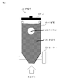
- the drying tower 120 is a device for drying the hydrogen gas flowing in from the inflow pipe 111.
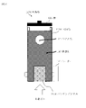
- the configuration of the drying tower 120 will be described with reference to FIG.
- the drying tower 120 includes a storage box 121, a lid 123, and a heater 124.
- the storage box 121 is filled with a desiccant 130 for drying hydrogen gas.
- the desiccant 130 is a porous ceramic.
- the desiccant 130 is activated alumina, silica gel, zeolite, microporous silica, or the like. From the viewpoint of availability, activated alumina or silica gel is desirable as the desiccant 130.
- the storage box 121 has a peephole 122 for confirming the color of the desiccant 130 from the outside.
- the location where the peephole 122 is provided may be moved or increased or decreased depending on the operation.
- Hydrogen gas flows into the storage box 121 from below the storage box 121.
- the upper part of the storage box 121 has a cylindrical shape.
- the lower part of the storage box 121 has a conical shape, a funnel shape, or a tapered shape with a narrowed lower side. That is, the diameter near the entrance of the storage box 121 is small, and the diameter becomes larger toward the upper part. As a result, the hydrogen gas easily comes into contact with the desiccant 130, and the desiccant effect can be enhanced.
- the lid 123 can be freely attached to and removed from the drying tower 120.
- the heater 124 heats the desiccant 130. As a result, the water adsorbed on the desiccant 130 is removed.
- FIG. 3 shows a cross section of a single desiccant 130.
- An index agent 131 whose hue changes is attached to the surface of the desiccant 130.
- the indicator 131 reversibly changes color in response to moisture.
- the indicator 131 is cobalt chloride.
- a cobalt chloride-free material such as tetraphenylporphyrin chloride or iron alum may be used as the indicator 131.
- the index agent 131 may be determined according to the specifications of the gas drying system 100 regarding the heat resistance of the material, the reversibility of discoloration, the ease of discriminating discoloration, and the like.
- the index agent 131 is combined with the desiccant 130, and when the desiccant 130 absorbs moisture, the color of the index agent 131 changes. By visually confirming the color of the index agent 131, the life of the desiccant 130 can be confirmed. The visual confirmation can be performed from the peep window 122 provided in the storage box 121.
- the desiccant 130 may be spherical or non-spherical. Further, the desiccant 130 may have a crushed shape. However, when the desiccant 130 has a spherical shape, the filling rate of the desiccant 130 in the storage box 121 increases, and the drying efficiency increases.
- the drying tower 120 dries the inflowing hydrogen gas with the desiccant 130.
- the dried hydrogen gas flows from the drying tower 120 through the outflow pipe 112, passes through the pipe switching machine 113, flows through the return pipe 114, and returns to the rotary electric machine 101.
- a gas drying system 100 for reactivating the desiccant 130 will be described with reference to FIG.
- the operation of the rotary electric machine 101 is stopped.
- the piping valve 102 and the piping valve 103 are closed.
- the valve to which the return pipe 114 is connected is closed.
- the valve to which the outflow pipe 112 is connected and the valve to which the drain pipe 115 is connected are opened.
- the heater 124 of the drying tower 120 generates heat to heat the desiccant 130.
- the temperature at which the desiccant 130 is heated is equal to or higher than the boiling point of water. However, it is necessary to consider the heat resistant temperature of the parts of the gas dryer 110.
- the desiccant 130 may be warmed at about 120 degrees.
- water vapor generated from the water adsorbed on the desiccant 130 flows through the outflow pipe 112, passes through the pipe switching machine 113, and flows through the drain pipe 115. Then, the water vapor is discharged to the outside from the drain pipe 115 as drain water 129.
- the gas drying system 100 has the following features.
- the lubricating oil 132 is used in various places. Therefore, the lubricating oil 132 may be mixed with the hydrogen gas during operation and flow in a mist state. Then, when the hydrogen gas is dried in the drying tower 120, the lubricating oil 132 mixed with the hydrogen gas adheres to the desiccant 130.
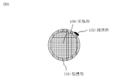
- FIG. 5 shows the desiccant 130 immediately after the lubricating oil 132 is attached.
- the desiccant 130 has a plurality of holes. Each pore of the desiccant 130 has a pore diameter equal to or larger than the size of the molecule of the lubricating oil 132. Therefore, the lubricating oil 132 adhering to the desiccant 130 penetrates into each hole of the desiccant 130 due to the capillary phenomenon.
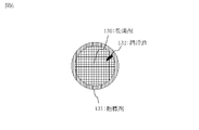
- FIG. 6 shows a desiccant 130 in which the lubricating oil 132 has penetrated. Since the lubricating oil 132 penetrates into the desiccant 130, the lubricating oil 132 is not exposed to air. That is, the lubricating oil 132 is less likely to deteriorate and discolor. Therefore, the color change of the index agent 131 can be observed.
- FIG. 7 shows a desiccant 139 as a comparative example with respect to the desiccant 130.
- the desiccant 139 has a plurality of holes. However, each pore of the desiccant 139 has a pore diameter smaller than the size of the molecule of the lubricating oil 132. Since the lubricating oil 132 cannot penetrate into each hole of the desiccant 139, it stays on the surface of the desiccant 139. Then, the lubricating oil 132 deteriorates and turns brown. In this case, it becomes difficult to observe the color change of the index agent 131.
- the entire surface of the desiccant 139 looks brown, so that the color change of the indicator 131 cannot be observed.
- FIG. 8 shows a specific example of the molecular structure of the lubricating oil 132.
- the molecular length of the lubricating oil 132 is 5.1 nanometers. This length is determined based on the molecular weight and the interatomic distance.
- the pore diameter of the desiccant 130 is less than 5.1 nanometers, the lubricating oil 132 cannot enter the pores, so that the capillary phenomenon does not occur.
- the pore diameter of the desiccant 130 is 5.1 nanometers or more. Therefore, the lubricating oil 132 can enter the pores, and a capillary phenomenon occurs. As a result, discoloration of the lubricating oil 132 does not occur.
- Each pore of the desiccant 139 has a pore diameter equal to or less than the wavelength of visible light.
- the lower limit of the wavelength of visible light is 360 nanometers.
- the color of the desiccant 130 may look different due to the influence of the lubricating oil 132 that has penetrated into each pore. In this case, even if the lubricating oil 132 does not change color due to deterioration, it becomes difficult to identify the color of the indicator 131. Therefore, the pore diameter of the desiccant 130 is preferably 360 nanometers or less.
- the pore volume of the desiccant 139 per cubic centimeter is 0.2 cubic centimeters or more and 0.7 cubic centimeters or less.
- the desiccant 139 takes in the lubricating oil 132 inside the pores. Therefore, if the space volume of the pores is small, the lubricating oil 132 may overflow on the surface of the desiccant 130 and discolor. On the other hand, if the space volume of the pores is too large, the strength of the desiccant 130 will be insufficient. Therefore, it is desirable that the volume of fine pores per cubic centimeter is 0.2 cubic centimeters or more and 0.7 cubic centimeters or less in a state where the desiccant 139 is filled. This value is obtained based on the bulk density [g / cm 3 ] and the pore volume [cm 3 / g].
- the pore volume is measured by a one-point method total pore volume measurement by a gas adsorption method using nitrogen.
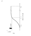
- FIG. 9 shows the relationship between the pore diameter and discoloration when the lubricating oil 132 of FIG. 8 is used. Looking at FIG. 9, it can be seen that discoloration is suppressed when the pore diameter is equal to or larger than the molecular size of the lubricating oil 132.
- the phenomenon of discoloration is determined by the capillary phenomenon with the pore diameter of the desiccant 130 and the molecular size of the lubricating oil 132 as parameters. Therefore, the maximum value of the pore diameter of the desiccant 130 may be larger than the molecular size of the lubricating oil 132.
- the maximum value of the pore diameter is obtained by measuring the pore distribution by the gas adsorption method and specifying the pore diameter that becomes the maximum in the pore distribution.
- the drying tower 120A is an example of the drying tower 120.
- the drying tower 120A includes a storage box 121A.
- the storage box 121A is provided with a cylindrical punching metal 125A at the bottom. Hydrogen gas flows into the storage box 121A from each hole of the punching metal 125A. Since hydrogen gas flows from the side surface of the punching metal 125A in each direction of 360 degrees, the drying effect is enhanced.
- the drying tower 120B is an example of the drying tower 120.
- the drying tower 120B includes a storage box 121B.
- the storage box 121B is filled with the desiccant 130 and the desiccant 130B in two upper and lower stages. That is, the desiccant 130 and the desiccant 130B are filled in layers with each other.
- the desiccant 130 and the desiccant 130B differ in at least one of the pore diameter and the material. As a result, two types of drying characteristics can be obtained.
- the storage box 121B may be filled with three or more kinds of desiccants. Three or more kinds of desiccants are filled in a drying tower in layers for each kind. Further, the storage box 121B may be provided separately for each layer.
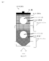
- the storage box 121B has a peephole 122 for confirming the desiccant 130 and a peephole 122B for confirming the desiccant 130B. That is, the storage box 121B has a viewing window for each desiccant. However, the storage box 121B may have one peephole.
- the storage box 121B includes a heater 124 for heating the desiccant 130 and a heater 124B for heating the desiccant 130B.
- the storage box 121B may include only the heater 124.
- the heat of the heater 124 reactivates the desiccant 130.
- the heat of the heater 124 dries the hydrogen gas. Then, the desiccant 130B can be reactivated by the flow of the dried hydrogen gas.
- the gas drying system 100C is an example of the gas drying system 100.
- the gas drying system 100C includes a drying tower 120C outside the gas dryer 110.
- the drying tower 120C is connected to the outlet side of the outflow pipe 112.
- the drying column 120C is filled with a desiccant having at least one of a pore diameter and a material different from that of the desiccant 130 of the drying column 120. As a result, two types of drying characteristics can be obtained.
- the drying tower 120C dries the hydrogen gas flowing in from the outflow pipe 112 with a desiccant.
- Each of the drying tower 120 and the drying tower 120C may be provided with a heater, or only the drying tower 120 may be provided with a heater 124.
- the heat of the heater 124 can reactivate the desiccant 130 in the drying column 120. Further, the heat of the heater 124 dries the hydrogen gas. Then, the desiccant in the drying tower 120C can be reactivated by the flow of the dried hydrogen gas.
- the gas drying system 100C may be provided with yet another drying tower.
- the gas drying system 100 dries hydrogen gas with a desiccant 130 using an index agent 131.
- the maximum pore diameter obtained when the pore distribution of the desiccant 130 is measured is a size at which the lubricating oil 132 can penetrate into the pores due to the capillary phenomenon. Since the lubricating oil 132, which causes discoloration, does not stay on the surface of the desiccant 130, discoloration of the lubricating oil 132 is prevented, and the color change of the desiccant 130 can be identified. This contributes to maintaining the purity of hydrogen gas and can achieve the effect of stabilizing the performance of the product.
- Embodiment 2 The mode of recovering the lubricating oil 132 mixed with the hydrogen gas will be described mainly different from the first embodiment with reference to FIGS. 13 to 17.
- the configuration of the gas drying system 100 further includes an oil removing device 140.
- the oil removing device 140 is connected in the middle of the inflow pipe 111, and removes the lubricating oil 132 from the hydrogen gas flowing through the inflow pipe 111 in a cyclone manner.
- the cyclone type is advantageous in terms of no pressure loss. For example, in a method in which an oil removing filter is used, a pressure loss occurs due to clogging of the filter, and the function of the oil removing device is deteriorated.
- the configuration of the oil removing device 140 will be described with reference to FIG.
- the oil removing device 140 includes a container 141.
- the container 141 has a conical inner surface. Hydrogen gas flows in a spiral along the inner surface of the container 141.
- the inclination angle ⁇ of the inner surface and the static friction coefficient ⁇ of the inner surface satisfy tan ⁇ ⁇ 1 / ⁇ .
- the inner surface of the container 141 is coated. For example, either a fluororesin coating, a ceramic coating or a glass coating is used.
- Hydrogen gas containing a small amount of lubricating oil 132 flows into the oil removing device 140.
- the hydrogen gas flows into the oil removing device 140, it flows downward along the inner surface of the container 141 in a spiral shape.
- the liquid lubricating oil 132 remains on the inner surface of the container 141.
- the lubricating oil 132 is removed from the hydrogen gas.
- the hydrogen gas reaches the lower part of the container 141, it is discharged to the outside from the upper part of the container 141 by the updraft.
- the lubricating oil 132 flows downward on the inner surface of the container 141.
- the lubricating oil 132 is recovered from the drain provided below the container 141.
- the valve 142 to which the drain is connected is closed when the rotary electric machine 101 is in operation and opened when the lubricating oil 132 is recovered.
- the oil removing device 140 has the following features in addition to the above-mentioned configuration and function.
- M means the weight [kg] of one grain of lubricating oil 132.
- G means gravitational acceleration [m / s 2 ].
- ⁇ means the inclination angle of the inner surface of the container 141.
- ⁇ means the coefficient of static friction on the inner surface of the container 141.
- N means the normal force [N] on the inner surface of the container 141.
- Equation (3) holds based on equations (1) and (2).
- the lubricating oil 132 flows downward on the inner surface of the container 141. Then, the lubricating oil 132 can be recovered.
- metals such as iron or aluminum are commonly used.
- the inner surface of the container 141 is made of metal, the coefficient of static friction is large, so that the range of tan ⁇ is narrowed and the degree of freedom in designing the container 141 is reduced. Therefore, the inner surface of the container 141 is coated.
- the coating material for example, a fluororesin coating, a ceramic coating or a glass coating can be used. This lowers the coefficient of static friction and increases the degree of freedom in designing the container 141.
- the oil removing device 140 removes the lubricating oil 132, it is possible to prevent discoloration of the desiccant 130 due to deterioration of the lubricating oil 132.
- the gas drying system 100 includes a cyclone type oil removing device 140. As a result, the lubricating oil 132 that causes discoloration can be removed as much as possible. Then, the distinctiveness of the color change of the desiccant 130 is further improved.
- Whether the lubricating oil penetrates into the desiccant due to the capillary phenomenon or stays on the surface of the desiccant can be investigated by the following method based on the weight change before and after the use of the desiccant.
- the desiccant is then sufficiently dried to remove water from the desiccant. For example, the desiccant is dried at 100 degrees for 2 hours. The desiccant is then weighed and recorded. The weight at this time is referred to as weight A.
- the weight A is the weight of the desiccant.
- the desiccant is used in the hydrogen gas containing the lubricating oil.
- the desiccant is then washed with a solution containing the detergent.
- the desiccant is then sufficiently dried to remove water from the desiccant. For example, the desiccant is dried at 100 degrees for 2 hours.
- the weight of the desiccant is measured and recorded. The weight at this time is referred to as weight B.
- the weight B is the sum of the weight of the desiccant and the weight of the lubricating oil.
- the weight B becomes a slightly larger value than the weight A. In this case, the rate of change in weight is less than 10 ppm.
- the rate of change in weight is 10 ppm or more.
- the pore volume of the desiccant is small, the volume for taking in the lubricating oil is small. On the other hand, if the pore volume of the desiccant is too large, the strength of the desiccant will be insufficient. Therefore, the pore volume per cubic centimeter is preferably 0.2 cubic centimeter or more and 0.7 cubic centimeter or less.
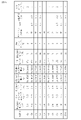
- FIG. 17 shows the test results of Comparative Examples (A to D).
- the pore size of the desiccant is 420 nanometers, which exceeds 360 nanometers.
- the discoloration level was 4 or 5. That is, the comparative examples (A to D) did not satisfy the practical level.
- the pore size of the desiccant is larger than the molecular size of the lubricating oil.
- the weight change rate of the desiccant was 10 ppm or more. That is, it was found that the lubricating oil penetrated into the pores of the desiccant due to the capillary phenomenon.
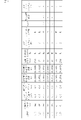
- FIG. 17 shows the test results of Comparative Examples (E, F).
- Comparative Examples (E, F) the pore size of the desiccant is smaller than the molecular size of the lubricating oil.
- the discoloration level was 4 or 5. That is, the comparative examples (E, F) did not satisfy the practical level.
- the weight change rate of the desiccant was less than 10 ppm. That is, it was found that the lubricating oil did not penetrate into the pores of the desiccant due to the capillary phenomenon.
- the pore volume per cubic centimeter is different within the range of 0.2 cubic centimeter or more and 0.7 cubic centimeter or less. However, there was no difference in the level of change.
- Examples (1, 5, 6, 7, 11, 12, 16, 17) and Comparative Examples (A, E) are not provided with an oil removing device. In this case, no change was observed in the discoloration level.
- the embodiments (2, 3, 8, 9, 13, 14) include an oil removing device.
- the oil removing device includes a container 141 satisfying the above formula (3). In this case, it was confirmed that the discoloration level was further lowered.
- the pore diameter of the desiccant is outside the range of 5.1 nanometers or more and 360 nanometers or less. In this case, it was found that even if an oil removing device was introduced, the discoloration level of the desiccant could not be brought to a practical level.
- the gas drying system 100 may be a system for drying hydrogen gas of a device other than the rotary electric machine 101.
- the gas drying system 100 may be a system for drying a gas other than hydrogen gas.
- the oil mixed with the hydrogen gas may be an oil other than the oil used as the lubricating oil 132.
- Each embodiment is an example of a preferred embodiment and is not intended to limit the technical scope of the present disclosure. Each embodiment may be partially implemented or may be implemented in combination with other embodiments.
- 100 gas drying system 101 rotary electric machine, 102 piping valve, 103 piping valve, 110 gas dryer, 111 inflow pipe, 112 outflow pipe, 113 piping switching machine, 114 return pipe, 115 drain pipe, 120 drying tower, 120A drying tower , 120B drying tower, 120C drying tower, 121 storage box, 121A storage box, 121B storage box, 122 peep window, 122B peep window, 123 lid, 124 heater, 124B heater, 125A punching metal, 130 desiccant, 130B desiccant, 131 indicator, 132 lubricating oil, 139 desiccant, 140 oil remover, 141 container, 142 valve.
Landscapes
- Chemical & Material Sciences (AREA)
- Engineering & Computer Science (AREA)
- Analytical Chemistry (AREA)
- Chemical Kinetics & Catalysis (AREA)
- Power Engineering (AREA)
- General Chemical & Material Sciences (AREA)
- Oil, Petroleum & Natural Gas (AREA)
- Inorganic Chemistry (AREA)
- Organic Chemistry (AREA)
- Drying Of Gases (AREA)
- Drying Of Solid Materials (AREA)
- Motor Or Generator Cooling System (AREA)
Abstract
Description
一般的に乾燥剤として、活性アルミナが用いられる。活性アルミナは、色標が変化する指標剤(Drying indicating agent whose color phase changes)として用いられる塩化コバルトと複合化される。そのため、水分が存在しない場合、塩化コバルトと複合化された活性アルミナは青色である。また、水分が存在する場合、活性アルミナが吸湿するとともに塩化コバルトが赤色に変化する。これにより、活性アルミナの寿命と水素ガス中の水分を目視で判断できる。
乾燥剤が吸湿によって寿命を迎えた場合、加温等で乾燥剤の中の水分を取り除いて乾燥剤を再利用する運用が行われる。
高い湿度を扱う分野において、乾燥剤を用いて湿度をコントロールする手法はよく知られた技術である。そのため、水素ガス乾燥器にも乾燥剤が用いられている。しかし、一般的に、高い湿度を扱う分野では、湿度と油ミストが共存することはない。そのため、油ミストが乾燥剤の表面に付着して変色する現象は知られていない。この現象は、ガス乾燥器に特有な現象である。そして、この現象は、乾燥剤を用いて湿度をコントロールする手法において改善されていない。
水分を含み油が混ざったガスが流れる流入管と、
乾燥剤が充填され、前記流入管から流入するガスを前記乾燥剤によって乾燥させる乾燥塔と、
前記乾燥塔で乾燥したガスが流れる流出管と、
を備える。
前記乾燥剤が、前記油の分子の大きさ以上の細孔径を有して前記油が浸入する複数の孔を持つ。
ガス乾燥システム100について、図1から図12に基づいて説明する。
図1に基づいて、ガス乾燥システム100の構成を説明する。
ガス乾燥システム100は、回転電機101と、ガス乾燥器110と、を備える。
回転電機101は、配管バルブ102と、配管バルブ103と、を備える。
ガス乾燥器110は、乾燥塔120を備える。また、ガス乾燥器110は、流入管111と、流出管112と、配管切替機113と、戻り管114と、排水管115と、を備える。
流入管111は、回転電機101と乾燥塔120を繋げる配管である。配管バルブ102が開いている場合、水素ガスは、流入管111を流れて乾燥塔120に流入する。
流出管112は、乾燥塔120と配管切替機113とを繋げる配管である。水素ガスは、乾燥塔120から流出して流出管112を流れる。
配管切替機113は、流路を切り替えるための機器であり、流出管112が連結されるバルブと、戻り管114が連結されるバルブと、排水管115が連結されるバルブとを備える。
戻り管114は、回転電機101と配管切替機113とを繋げる配管である。配管バルブ103と配管切替機113のバルブのうち排水管115のためのバルブ以外が開いている場合、水素ガスは、戻り管114を流れて回転電機101に戻る。
排水管115は、ドレイン水を排出するための配管である。
乾燥塔120は、収納箱121と、蓋123と、ヒーター124と、を備える。
乾燥剤130は、多孔質セラミックである。例えば、乾燥剤130は、活性アルミナ、シリカゲル、ゼオライトまたはマイクロポーラスシリカ等である。入手性の観点から、乾燥剤130は活性アルミナまたはシリカゲルが望ましい。
収納箱121の上部は、円筒形状を成す。収納箱121の下部は、下側が狭まった円錐形状、ロート形状またはテーパー形状を成す。つまり、収納箱121の入口付近の径が細く、上部に向かうにつれて径が太くなる。これにより、水素ガスが乾燥剤130にふれやすくなり、乾燥効果を高めることができる。
乾燥剤130の表面には、色相が変化する指標剤131が付けられる。
指標剤131は、水分に反応して可逆的に変色する。具体的には、指標剤131は塩化コバルトである。但し、テトラフェニルポルフィリン塩化物または鉄ミョウバンなどの塩化コバルトフリーの材料が指標剤131として用いられてもよい。指標剤131は、材料の耐熱性、変色の可逆性および変色の判別容易性などについてのガス乾燥システム100の仕様に応じて決めるとよい。塩化コバルトフリーの材料であれば、規制物質の観点からテトラフェニルポルフィリン塩化物が望ましい。
指標剤131は乾燥剤130と複合化され、乾燥剤130が吸湿すると指標剤131の色が変わる。指標剤131の色を目視で確認することにより、乾燥剤130の寿命を確認することができる。目視の確認は、収納箱121に設けられたのぞき窓122から行うことができる。
ただし、乾燥剤130が球形状を成す方が、収納箱121における乾燥剤130の充填率が高まり、乾燥効率が高まる。
図1に基づいて、回転電機101の運転中におけるガス乾燥システム100について説明する。
回転電機101では、内部を冷却するための冷却媒体として水素ガスが使用される。
水素ガスは、回転電機101から流入管111を流れて乾燥塔120に流入する。
この水素ガスは、回転電機101で吸湿して水分を含んでいる。
乾燥した水素ガスは、乾燥塔120から流出管112を流れ、配管切替機113を経由し、戻り管114を流れ、回転電機101に戻る。
回転電機101の運転は停止される。
配管バルブ102および配管バルブ103は閉じられる。
配管切替機113において、戻り管114が連結したバルブは閉じられる。また、流出管112が連結したバルブと排水管115が連結したバルブが開かれる。
乾燥塔120のヒーター124は、熱を発して乾燥剤130を温める。これにより、乾燥剤130に吸着している水分が取り除かれる。乾燥剤130を温める温度は、水分の沸点以上である。ただし、ガス乾燥器110の部品の耐熱温度を考慮する必要がある。例えば、乾燥剤130は120度程度で温めるとよい。
この状態で一定時間が経過すると、乾燥剤130に吸着していた水分から生じた水蒸気が流出管112を流れ、配管切替機113を経由し、排水管115を流れる。そして、水蒸気は、ドレイン水129として排水管115から外部に放出される。
ガス乾燥システム100は、上記の構成および機能の他に、以下のような特徴を有する。
回転電機101では、様々なところに潤滑油132が使用されている。そのため、潤滑油132が運転時の水素ガスに混ざってミスト状態で流れることがある。そして、水素ガスが乾燥塔120で乾燥される際に、水素ガスに混ざった潤滑油132が乾燥剤130に付着する。
図5に、潤滑油132が付着した直後の乾燥剤130を示す。
図6に、潤滑油132が内部に浸入した乾燥剤130を示す。潤滑油132は乾燥剤130の内部に浸入するので、潤滑油132は空気にさらされない。つまり、潤滑油132は劣化しにくく変色しにくい。そのため、指標剤131の色変化を観察することができる。
乾燥剤139は複数の孔を持つ。ただし、乾燥剤139の各孔は潤滑油132の分子の大きさ未満の細孔径を有する。
潤滑油132は、乾燥剤139の各孔に浸入できないため、乾燥剤139の表面に留まる。そして、潤滑油132は劣化して茶褐色に変色する。
この場合、指標剤131の色変化を観察しにくくなる。例えば、乾燥剤139の全面に潤滑油132が付着し、潤滑油132が茶褐色に変色した場合、乾燥剤139の全面が茶褐色に見えるため、指標剤131の色変化を観察できない。
潤滑油132の分子の長さは、5.1ナノメートルである。この長さは、分子量と原子間距離とに基づいて求まる。
乾燥剤130の細孔径が5.1ナノメートル未満である場合、潤滑油132が細孔内に入ることができないため、毛細管現象は起こらない。
乾燥剤130の細孔径は5.1ナノメートル以上である。そのため、潤滑油132が細孔内に入ることができ、毛細管現象が起こる。その結果、潤滑油132の変色が起こらなくなる。
可視光の波長の下限は360ナノメートルである。
乾燥剤130の細孔径が360ナノメートルを超える場合、各細孔の内部に浸入した潤滑油132の影響により、乾燥剤130の色が違って見えることがある。この場合、潤滑油132が劣化によって変色しなくても、指標剤131の色の識別がしにくくなる。そのため、乾燥剤130の細孔径は360ナノメートル以下が望ましい。
乾燥剤139は細孔内部に潤滑油132を取り込む。そのため、細孔の空間体積が小さいと、潤滑油132が乾燥剤130の表面に溢れて変色することがある。一方で、細孔の空間体積が大きすぎると、乾燥剤130の強度不足が生じてしまう。
そのため、乾燥剤139が充填された状態において、1立方センチメートルあたりの細細孔体積は0.2立方センチメートル以上0.7立方センチメートル以下が望ましい。この数値は、かさ密度[g/cm3]と細孔体積[cm3/g]とに基づいて求められる。細孔体積は、窒素を用いたガス吸着法による1点法全細孔容積測定によって測定される。
図9を見ると、細孔径が潤滑油132の分子サイズ以上である場合に変色が抑制されることが分かる。
変色の現象は、乾燥剤130の細孔径と潤滑油132の分子サイズとをパラメータとする毛細管現象によって決まる。そのため、乾燥剤130の細孔径の極大値が潤滑油132の分子サイズ以上であればよい。
細孔径の極大値は、ガス吸着法によって細孔分布を測定し、細孔分布において極大となる細孔径を特定することによって求められる。
図10に基づいて、乾燥塔120Aについて主に乾燥塔120と異なる点を説明する。乾燥塔120Aは乾燥塔120の実施例である。
乾燥塔120Aは、収納箱121Aを備える。
収納箱121Aは、円筒形状のパンチングメタル125Aを下部に備える。水素ガスは、パンチングメタル125Aの各穴から収納箱121Aの中に流入する。
水素ガスがパンチングメタル125Aの側面から360度の各方向に流れるため、乾燥効果が高まる。
図11に基づいて、乾燥塔120Bについて主に乾燥塔120と異なる点を説明する。乾燥塔120Bは乾燥塔120の実施例である。
乾燥塔120Bは、収納箱121Bを備える。
収納箱121Bには、乾燥剤130と乾燥剤130Bが上下二段に分けて充填される。つまり、乾燥剤130と乾燥剤130Bは、互いに層を成して充填される。
乾燥剤130と乾燥剤130Bは、細孔径と材料との少なくともいずれかが異なる。これにより、2種類の乾燥特性が得られる。
ただし、収納箱121Bには、3種類以上の乾燥剤が充填されてもよい。3種類以上の乾燥剤は、種類ごとに層を成して乾燥塔に充填される。また、収納箱121Bは、層ごとに別々に設けてもよい。
ただし、収納箱121Bは、1つののぞき窓を有してもよい。
ただし、収納箱121Bは、ヒーター124のみを備えてもよい。この場合、ヒーター124の熱は、乾燥剤130を再活性化させる。また、ヒーター124の熱は、水素ガスを乾燥させる。そして、乾燥した水素ガスが流れることにより、乾燥剤130Bを再活性化することができる。
図12に基づいて、ガス乾燥システム100Cについて主にガス乾燥システム100と異なる点を説明する。ガス乾燥システム100Cはガス乾燥システム100の実施例である。
ガス乾燥システム100Cは、ガス乾燥器110の外部に乾燥塔120Cを備える。
乾燥塔120Cは、流出管112の出口側に接続される。
乾燥塔120Cには、乾燥塔120の乾燥剤130とは細孔径と材料との少なくともいずれかが異なる乾燥剤が充填される。これにより、2種類の乾燥特性が得られる。
乾燥塔120Cは、流出管112から流入する水素ガスを乾燥剤で乾燥させる。
乾燥塔120と乾燥塔120Cとのそれぞれがヒーターを備えてもよいし、乾燥塔120のみがヒーター124を備えてもよい。ヒーター124の熱は、乾燥塔120の乾燥剤130を再活性化することができる。また、ヒーター124の熱は、水素ガスを乾燥させる。そして、乾燥した水素ガスが流れることにより、乾燥塔120Cの乾燥剤を再活性化することができる。
ガス乾燥システム100Cは、さらに別の乾燥塔を備えてもよい。
ガス乾燥システム100は、指標剤131を用いた乾燥剤130によって水素ガスを乾燥させる。乾燥剤130の細孔分布を測定した際に得られる極大の細孔径が、潤滑油132が毛細管現象により細孔内に浸入できるサイズである。
変色の要因となる潤滑油132が乾燥剤130の表面に留まらないため、潤滑油132の変色が防止され、乾燥剤130の色変化の識別が可能になる。これにより、水素ガスの純度維持に貢献し、製品の性能安定化という効果を奏することができる。
水素ガスに混ざった潤滑油132を回収する形態について、主に実施の形態1と異なる点を図13から図17に基づいて説明する。
図13に基づいて、ガス乾燥システム100の構成を説明する。
ガス乾燥システム100は、さらに、油除去装置140を備える。
油除去装置140は、流入管111の途中に接続され、流入管111を流れる水素ガスから潤滑油132をサイクロン式で除去する。
サイクロン式は、圧力損失が生じないという観点で有利である。例えば、油除去フィルターが用いられる方式では、フィルターの目詰まりによって圧力損失が生じ、油除去装置の機能が低下してしまう。
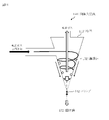
油除去装置140は、容器141を備える。
容器141は、円錐形状の内面を有する。水素ガスは、容器141の内面に沿って渦巻き状に流れる。
容器141において、内面の傾斜角度θと内面の静止摩擦係数μは、tanθ<1/μを満たす。
容器141の内面には、コーティングが施されている。例えば、フッ素樹脂コーティングとセラミックコーティングとガラスコーティングとのいずれかが用いられる。
図14に基づいて、油除去装置140の機能を説明する。
油除去装置140には、微量の潤滑油132を含有する水素ガスが流入する。
水素ガスは、油除去装置140に流入すると、容器141の内面に沿って渦巻き状に流れながら下方に落下する。このとき、液状の潤滑油132が容器141の内面に残る。これにより、水素ガスから潤滑油132が取り除かれる。
そして、水素ガスは、容器141の下方に到達すると、上昇気流によって容器141の上方から外部に排出される。
一方、潤滑油132は、容器141の内面を下方に流れる。そして、潤滑油132は、容器141の下方に設けられるドレインから回収される。なお、ドレインが接続されるバルブ142は、回転電機101の運転時には閉じられ、潤滑油132の回収時に開けられる。
油除去装置140は、上記の構成および機能の他に、以下のような特徴を有する。
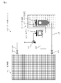
潤滑油132が容器141の内面を伝って落下を開始する場合、潤滑油132が落下する力に比較して最大静止摩擦力が小さいので、式(1)および式(2)が成り立つ。
「m」は、一粒の潤滑油132の重量[kg]を意味する。
「g」は、重力加速度[m/s2]を意味する。
「θ」は、容器141の内面の傾斜角度を意味する。
「μ」は、容器141の内面の静止摩擦係数を意味する。
「N」は、容器141の内面の垂直抗力[N]を意味する。
N=mgsinθ ・・・式(2)
コーティング材料として、例えば、フッ素樹脂コーティング、セラミックコーティングまたはガラスコーティングを用いることができる。
これにより、静止摩擦係数が下がり、容器141の設計の自由度が上がる。
ガス乾燥システム100はサイクロン式の油除去装置140を備える。これにより、変色の要因となる潤滑油132を極力除去することができる。そして、乾燥剤130の色変化の識別性がより向上する。
図15、図16および図17に、乾燥剤の変色レベルについての試験結果を示す。図15および図16は実施の形態の実施例における試験結果を示し、図17は実施の形態に対する比較例における試験結果を示す。
乾燥剤の細孔径の範囲は、5.1ナノメートル以上420ナノメートル以下である。
潤滑油の分子サイズの範囲は、2.8ナノメートル以上8.6ナノメートル以下である。
乾燥剤の変色レベルは、5段階で示される。数字が小さいほど変色が少ない。3以下の変色レベルは実用可能レベルである。
まず、乾燥剤を一定量用意する。具体的には、50グラム程度の乾燥剤を用意することが望ましい。ここでは、乾燥剤として活性アルミナを使用し、指標剤として塩化コバルトを使用した。
次に、乾燥剤を十分に乾燥させて、乾燥剤から水分を取り除く。例えば、乾燥剤を100度で2時間乾燥させる。
次に、乾燥剤の重量を測定して記録する。このときの重量を重量Aと称する。重量Aは、乾燥剤の重量である。
次に、潤滑油が含まれる水素ガスの中で乾燥剤を使用する。
次に、界面活性剤を含む溶液で乾燥剤を洗浄する。
次に、乾燥剤を十分に乾燥させて、乾燥剤から水分を取り除く。例えば、乾燥剤を100度で2時間乾燥させる。
そして、乾燥剤の重量を測定して記録する。このときの重量を重量Bと称する。重量Bは、乾燥剤の重量と潤滑油の重量との合計である。
一方、毛細管現象が起こった場合、潤滑油が乾燥剤の内部に含まれるため、潤滑油が洗浄によって除去されない。そのため、重量Bは重量Aに比較して大きい値となる。この場合、重量の変化率は10ppm以上になる。
図17は、比較例(A~D)の試験結果を示している。乾燥剤の細孔径は、420ナノメートルであり、360ナノメートルを超えている。変色レベルは4または5であった。つまり、比較例(A~D)は実用可能レベルを満たさなかった。
また、上記の方法によって測定した結果、乾燥剤の重量変化率は10ppm未満であった。つまり、潤滑油が毛細管現象によって乾燥剤の細孔内部に浸入していないことが分かった。
実施例(2、3、8、9、13、14)は、油除去装置を備える。油除去装置は、上記の式(3)を満たす容器141を備える。この場合、変色レベルがさらに下がることが確認された。
比較例(B、C、D、F)では、乾燥剤の細孔径が5.1ナノメートル以上360ナノメートル以下の範囲外である。この場合、油除去装置を導入しても乾燥剤の変色レベルを実用可能レベルにできないことが分かった。
ガス乾燥システム100は、回転電機101ではない機器の水素ガスを乾燥させるシステムであってもよい。
ガス乾燥システム100は、水素ガスではないガスを乾燥させるシステムであってもよい。
水素ガスに混ざる油は、潤滑油132として使用される油以外の油であってもよい。
Claims (15)
- 水分を含み油が混ざったガスが流れる流入管と、
乾燥剤が充填され、前記流入管から流入するガスを前記乾燥剤によって乾燥させる乾燥塔と、
前記乾燥塔で乾燥したガスが流れる流出管と、
を備え、
前記乾燥剤が、前記油の分子の大きさ以上の細孔径を有して前記油が浸入する複数の孔を持つ
ガス乾燥システム。 - 前記乾燥剤が、水分に反応して変色する指標剤と複合化され、
前記乾燥剤の前記細孔径が、可視光の波長以下である
請求項1に記載のガス乾燥システム。 - 前記乾燥剤の前記細孔径として前記乾燥剤の細孔分布における細孔径の極大値が5.1ナノメートル以上360ナノメートル以下である
請求項1または請求項2に記載のガス乾燥システム。 - 充填された乾燥剤の1立方センチメートルあたりの細孔体積が0.2立方センチメートル以上0.7立方センチメートル以下である
請求項1から請求項3のいずれか1項に記載のガス乾燥システム。 - 前記乾燥剤が、シリカゲルと活性アルミナとゼオライトとマイクロポーラスシリカとのいずれかである
請求項1から請求項4のいずれか1項に記載のガス乾燥システム。 - 前記ガスが、前記油である潤滑油が使用される回転電機で冷却媒体として使用され前記回転電機から流れる水素ガスである
請求項1から請求項5のいずれか1項に記載のガス乾燥システム。 - 前記乾燥塔が、前記乾燥剤が充填される収納箱を備え、
前記収納箱が、前記流入管から前記ガスが流入する部分が狭まった形状を有する
請求項1から請求項6のいずれか1項に記載のガス乾燥システム。 - 前記乾燥塔が、前記乾燥剤が充填される収納箱を備え、
前記収納箱が、前記流入管から前記ガスが流入する部分にパンチングメタルを備える
請求項1から請求項6のいずれか1項に記載のガス乾燥システム。 - 前記乾燥剤が、細孔径と材料との少なくともいずれかが異なる複数種類の乾燥剤のうちの一つであり、
前記複数種類の乾燥剤が、種類ごとに層を成して前記乾燥塔に充填される
請求項1から請求項8のいずれか1項に記載のガス乾燥システム。 - 前記ガス乾燥システムは、
前記流入管と前記乾燥塔である第1乾燥塔と前記流出管とを備えるガス乾燥器と、
前記流出管の出口側に接続され、前記第1乾燥塔の前記乾燥剤とは細孔径と材料との少なくともいずれかが異なる乾燥剤が充填され、前記流出管から流入するガスを乾燥させる第2乾燥塔と、
を備える
請求項1から請求項8のいずれか1項に記載のガス乾燥システム。 - 前記ガス乾燥システムは、
前記流入管と前記乾燥塔と前記流出管とを備えるガス乾燥器と、
前記流入管の途中に接続され、前記流入管を流れるガスから前記油をサイクロン式で除去する油除去装置と、
を備える
請求項1から請求項10のいずれか1項に記載のガス乾燥システム。 - 前記油除去装置は、円錐形状の内面を有し、前記ガスが前記内面に沿って渦巻き状に流れる容器を備え、
前記内面の傾斜角度θと前記内面の静止摩擦係数μが、tanθ<1/μを満たす
請求項11に記載のガス乾燥システム。 - コーティングが前記内面に施された請求項12に記載のガス乾燥システム。
- 前記コーティングが、フッ素樹脂コーティングとセラミックコーティングとガラスコーティングとのいずれかである
請求項13に記載のガス乾燥システム。 - 水分を含み油が混ざったガスが流れる流入管と、
乾燥剤が充填され、前記流入管から流入するガスを前記乾燥剤によって乾燥させる乾燥塔と、
前記乾燥塔で乾燥したガスが流れる流出管と、
を備え、
前記乾燥剤が、前記油の分子の大きさ以上の細孔径を有して前記油が浸入する複数の孔を持つ
ガス乾燥器。
Priority Applications (4)
| Application Number | Priority Date | Filing Date | Title |
|---|---|---|---|
| PCT/JP2020/048521 WO2022137451A1 (ja) | 2020-12-24 | 2020-12-24 | ガス乾燥システムおよびガス乾燥器 |
| CN202080107913.7A CN116569453A (zh) | 2020-12-24 | 2020-12-24 | 气体干燥系统及气体干燥器 |
| US18/036,660 US20240022139A1 (en) | 2020-12-24 | 2020-12-24 | Gas drying system and gas drier |
| JP2022570900A JP7370481B2 (ja) | 2020-12-24 | 2020-12-24 | ガス乾燥システムおよびガス乾燥器 |
Applications Claiming Priority (1)
| Application Number | Priority Date | Filing Date | Title |
|---|---|---|---|
| PCT/JP2020/048521 WO2022137451A1 (ja) | 2020-12-24 | 2020-12-24 | ガス乾燥システムおよびガス乾燥器 |
Publications (1)
| Publication Number | Publication Date |
|---|---|
| WO2022137451A1 true WO2022137451A1 (ja) | 2022-06-30 |
Family
ID=82159312
Family Applications (1)
| Application Number | Title | Priority Date | Filing Date |
|---|---|---|---|
| PCT/JP2020/048521 Ceased WO2022137451A1 (ja) | 2020-12-24 | 2020-12-24 | ガス乾燥システムおよびガス乾燥器 |
Country Status (4)
| Country | Link |
|---|---|
| US (1) | US20240022139A1 (ja) |
| JP (1) | JP7370481B2 (ja) |
| CN (1) | CN116569453A (ja) |
| WO (1) | WO2022137451A1 (ja) |
Citations (4)
| Publication number | Priority date | Publication date | Assignee | Title |
|---|---|---|---|---|
| JP2013162647A (ja) * | 2012-02-06 | 2013-08-19 | Toshiba Corp | 発電機冷却用水素ガス乾燥装置及び運転方法 |
| JP2013252474A (ja) * | 2012-06-06 | 2013-12-19 | Mitsubishi Electric Corp | 電気機械用ガス乾燥器 |
| JP2015177560A (ja) * | 2014-03-13 | 2015-10-05 | 三菱電機株式会社 | 水素ガス乾燥装置およびこれを備えた回転電機システム |
| WO2016199274A1 (ja) * | 2015-06-11 | 2016-12-15 | 三菱電機株式会社 | 回転電機のガス乾燥器 |
Family Cites Families (7)
| Publication number | Priority date | Publication date | Assignee | Title |
|---|---|---|---|---|
| NL275719A (ja) * | 1961-03-08 | |||
| JPH09295811A (ja) * | 1996-04-30 | 1997-11-18 | Lion Corp | 無定形多孔体及びその製造方法 |
| JP2001246216A (ja) * | 1999-12-28 | 2001-09-11 | Denso Corp | 気液分離装置 |
| US7393381B2 (en) * | 2003-06-19 | 2008-07-01 | Applied Filter Technology, Inc. | Removing siloxanes from a gas stream using a mineral based adsorption media |
| KR101046774B1 (ko) * | 2009-08-12 | 2011-07-05 | (주)호성화학 | 다단 자가 지시능을 가지는 흡습제 및 그 제조방법 |
| CN104804571B (zh) * | 2014-02-19 | 2017-02-22 | 吉林市新谊化工防腐蚀材料有限责任公司 | 具有有机氟碳涂层的油管及有机氟碳涂料 |
| CN106540494A (zh) * | 2016-12-07 | 2017-03-29 | 中国科学院合肥物质科学研究院 | 一种氦制冷机中的压缩氦气除油净化系统 |
-
2020
- 2020-12-24 JP JP2022570900A patent/JP7370481B2/ja active Active
- 2020-12-24 WO PCT/JP2020/048521 patent/WO2022137451A1/ja not_active Ceased
- 2020-12-24 CN CN202080107913.7A patent/CN116569453A/zh not_active Withdrawn
- 2020-12-24 US US18/036,660 patent/US20240022139A1/en not_active Abandoned
Patent Citations (4)
| Publication number | Priority date | Publication date | Assignee | Title |
|---|---|---|---|---|
| JP2013162647A (ja) * | 2012-02-06 | 2013-08-19 | Toshiba Corp | 発電機冷却用水素ガス乾燥装置及び運転方法 |
| JP2013252474A (ja) * | 2012-06-06 | 2013-12-19 | Mitsubishi Electric Corp | 電気機械用ガス乾燥器 |
| JP2015177560A (ja) * | 2014-03-13 | 2015-10-05 | 三菱電機株式会社 | 水素ガス乾燥装置およびこれを備えた回転電機システム |
| WO2016199274A1 (ja) * | 2015-06-11 | 2016-12-15 | 三菱電機株式会社 | 回転電機のガス乾燥器 |
Also Published As
| Publication number | Publication date |
|---|---|
| JPWO2022137451A1 (ja) | 2022-06-30 |
| JP7370481B2 (ja) | 2023-10-27 |
| CN116569453A (zh) | 2023-08-08 |
| US20240022139A1 (en) | 2024-01-18 |
Similar Documents
| Publication | Publication Date | Title |
|---|---|---|
| US6890373B2 (en) | Adsorbents, process for producing the same, and applications thereof | |
| JP7404482B2 (ja) | 水素分離装置と水素分離方法 | |
| US5997618A (en) | Filter and method for making a filter | |
| US5879764A (en) | Desiccation using polymer-bound desiccant beads | |
| CN104168977B (zh) | 用于湿度控制通常用于控制集液罐的湿度的过滤器 | |
| US7179382B2 (en) | Coated activated carbon for automotive emission control | |
| US6165519A (en) | Filter for adsorption from and/or dispersion of ingredients into a fluid | |
| US4242206A (en) | Filter dehydrator | |
| Liew et al. | Fine mist filtration by wet filters—I. Liquid saturation and flow resistance of fibrous filters | |
| JPS6253676A (ja) | 多孔性のろ過用構造体 | |
| CN115837174A (zh) | 有机凝胶或液相色谱法 | |
| JP2010258318A (ja) | 吸湿呼吸装置 | |
| US20200164305A1 (en) | Absorbent apparatus for an air dryer purge air cleaner and method of producing the same | |
| WO2004022204A1 (en) | Dehydrating breather apparatus and method | |
| WO2022137451A1 (ja) | ガス乾燥システムおよびガス乾燥器 | |
| JP4627615B2 (ja) | 空気または他の気体から汚染物質を濾過するための濾過材および濾過方法 | |
| Trens et al. | A macrothermodynamic approach to the limit of reversible capillary condensation | |
| US12121852B2 (en) | Apparatus comprising a contaminant-resistant and non-corrosive desiccant composite with high moisture capacity | |
| JP6073134B2 (ja) | 媒体流を乾燥させる装置 | |
| Tarighi et al. | Green Synthesized Manganese‐Cobaltite Nanospinel and Its Dye Removal Characteristics: Isothermal and Kinetic Studies | |
| Masoumifard et al. | Zeolitic core@ shell adsorbents for the selective removal of free glycerol from crude biodiesel | |
| JPS63264125A (ja) | 乾式除湿材 | |
| CN209952527U (zh) | 一种用杠杆平衡阀调节露点的控制器 | |
| Afzal et al. | Surface characterization and heats of adsorption of chromatographic alumina gel | |
| JPS58109115A (ja) | ガス浄化用円筒状フィルタ−カ−トリッジ |
Legal Events
| Date | Code | Title | Description |
|---|---|---|---|
| 121 | Ep: the epo has been informed by wipo that ep was designated in this application |
Ref document number: 20966939 Country of ref document: EP Kind code of ref document: A1 |
|
| ENP | Entry into the national phase |
Ref document number: 2022570900 Country of ref document: JP Kind code of ref document: A |
|
| WWE | Wipo information: entry into national phase |
Ref document number: 18036660 Country of ref document: US |
|
| WWE | Wipo information: entry into national phase |
Ref document number: 202080107913.7 Country of ref document: CN |
|
| NENP | Non-entry into the national phase |
Ref country code: DE |
|
| 122 | Ep: pct application non-entry in european phase |
Ref document number: 20966939 Country of ref document: EP Kind code of ref document: A1 |