WO2022137441A1 - 無線通信装置及び制御方法 - Google Patents
無線通信装置及び制御方法 Download PDFInfo
- Publication number
- WO2022137441A1 WO2022137441A1 PCT/JP2020/048475 JP2020048475W WO2022137441A1 WO 2022137441 A1 WO2022137441 A1 WO 2022137441A1 JP 2020048475 W JP2020048475 W JP 2020048475W WO 2022137441 A1 WO2022137441 A1 WO 2022137441A1
- Authority
- WO
- WIPO (PCT)
- Prior art keywords
- antenna
- actuator
- rotation
- support portion
- extending direction
- Prior art date
- Legal status (The legal status is an assumption and is not a legal conclusion. Google has not performed a legal analysis and makes no representation as to the accuracy of the status listed.)
- Ceased
Links
Images



Classifications
-
- H—ELECTRICITY
- H01—ELECTRIC ELEMENTS
- H01Q—ANTENNAS, i.e. RADIO AERIALS
- H01Q1/00—Details of, or arrangements associated with, antennas
- H01Q1/12—Supports; Mounting means
- H01Q1/125—Means for positioning
-
- H—ELECTRICITY
- H01—ELECTRIC ELEMENTS
- H01Q—ANTENNAS, i.e. RADIO AERIALS
- H01Q3/00—Arrangements for changing or varying the orientation or the shape of the directional pattern of the waves radiated from an antenna or antenna system
- H01Q3/02—Arrangements for changing or varying the orientation or the shape of the directional pattern of the waves radiated from an antenna or antenna system using mechanical movement of antenna or antenna system as a whole
- H01Q3/04—Arrangements for changing or varying the orientation or the shape of the directional pattern of the waves radiated from an antenna or antenna system using mechanical movement of antenna or antenna system as a whole for varying one co-ordinate of the orientation
-
- H—ELECTRICITY
- H01—ELECTRIC ELEMENTS
- H01Q—ANTENNAS, i.e. RADIO AERIALS
- H01Q1/00—Details of, or arrangements associated with, antennas
- H01Q1/12—Supports; Mounting means
-
- H—ELECTRICITY
- H01—ELECTRIC ELEMENTS
- H01Q—ANTENNAS, i.e. RADIO AERIALS
- H01Q1/00—Details of, or arrangements associated with, antennas
- H01Q1/12—Supports; Mounting means
- H01Q1/18—Means for stabilising antennas on an unstable platform
-
- H—ELECTRICITY
- H01—ELECTRIC ELEMENTS
- H01Q—ANTENNAS, i.e. RADIO AERIALS
- H01Q1/00—Details of, or arrangements associated with, antennas
- H01Q1/27—Adaptation for use in or on movable bodies
- H01Q1/34—Adaptation for use in or on ships, submarines, buoys or torpedoes
Definitions
- the present invention relates to a wireless communication device and a control method.
- IoT Internet of Things
- base stations such as buoys and ships on the sea.
- UAVs Unmanned Aerial Vehicles
- artificial satellites collect the data acquired by such IoT terminals.
- Non-Patent Document 1 discloses a tracking 3-axis swivel device for tracking an object. By supporting the antenna with a swivel device as described in Non-Patent Document 1, it is possible to suppress a change in the direction of the antenna.
- Non-Patent Document 1 discloses an apparatus having a three-axis gimbal configuration. On the other hand, the more controllable axes the swivel device has, the more complicated the configuration becomes, and the larger the device size and power consumption.
- An object of the present invention is to provide a wireless communication device and a control method capable of maintaining the directivity direction of an antenna with a simple configuration.
- One aspect of the present invention is an antenna having a rod-shaped element, a support portion that rotatably supports the antenna around a rotation axis orthogonal to the extending direction of the element, and rotation of the antenna around the rotation axis.
- the antenna is provided with an actuator for supporting the support portion, a floating body that floats on water, a sensor for measuring a physical quantity related to the inclination of the support portion, and a control device, and the control device acquires the measured value of the sensor.
- It is a wireless communication device including a measured value acquisition unit and a rotation control unit that drives the actuator so that the direction in which the change in inclination is the smallest and the extending direction of the antenna coincide with each other based on the measured value.
- One aspect of the present invention is an antenna having a rod-shaped element, a support portion that rotatably supports the antenna around a rotation axis orthogonal to the extending direction of the antenna, and rotation of the antenna around the rotation axis. It is a control method of a wireless communication device including an antenna for making the support portion, a floating body that supports the support portion and floats on water, and a sensor for measuring a physical quantity related to the inclination of the support portion, and acquires the measured value of the sensor. This is a control method including a step of driving the actuator so that the direction in which the change in inclination indicated by the measured value is the smallest and the extending direction of the antenna coincide with each other.
- the directivity direction of the antenna can be maintained with a simple configuration.
- FIG. 1 is a configuration diagram of a wireless communication system 1 according to the first embodiment.
- the wireless communication system 1 has a mobile relay station 2, a terminal station 3, and a base station 4.
- the number of each of the mobile relay station 2, the terminal station 3, and the base station 4 included in the wireless communication system 1 is arbitrary, but it is assumed that the number of the terminal stations 3 is large.
- the mobile relay station 2 is an example of a relay device mounted on a mobile body and in which a communicable area moves with the passage of time.
- the mobile relay station 2 is provided in, for example, a LEO (Low Earth Orbit) satellite.
- the altitude of the LEO satellite is 2000 km or less, and it orbits over the earth in about 1.5 hours.
- the terminal station 3 and the base station 4 are installed on the earth such as on the ground or at sea.
- the terminal station 3 is, for example, an IoT terminal.
- the terminal station 3 collects data such as environmental data detected by the sensor and wirelessly transmits the data to the mobile relay station 2. In the figure, only two terminal stations 3 are shown.
- the mobile relay station 2 receives data transmitted from each of the plurality of terminal stations 3 by wireless signals while moving over the earth, and wirelessly transmits these received data to the base station 4.
- the base station 4 receives the data collected by the terminal station 3 from the mobile relay station 2.
- a geostationary satellite or a relay station mounted on an unmanned aerial vehicle such as a drone or HAPS (High Altitude Platform Station) may be used.
- the coverage area (footprint) on the ground is wider than that on the LEO satellite, but the altitude is high, so the IoT installed on the ground.
- the link budget for the terminal is small.
- the link budget is higher than that on the LEO satellite, but the coverage area is narrow.
- Unmanned aerial vehicles also require power sources (eg batteries and solar panels) to maintain altitude.
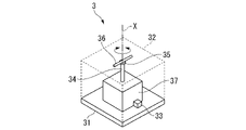
- FIG. 2 is a perspective view showing the appearance of the terminal station 3 according to the first embodiment.
- the terminal stations 3 at least those provided on the water include a floating body 31, a housing 32, a sensor group 33, a support portion 34, an actuator 35, an antenna 36, and a control device 37.
- the floating body 31 is a structure that floats on water.
- the housing 32 forms the outer shell of the terminal station 3.
- the housing 32 has high radio wave transmission and is waterproof.
- the sensor group 33 is attached to the floating body 31 and measures various physical quantities. Further, the sensor group 33 includes at least a sensor that measures a physical quantity related to the inclination of the floating body 31 with respect to the vertical direction.
- the sensor group 33 includes a three-axis accelerometer. The inclination of the floating body 31 with respect to the vertical direction can be specified by detecting the direction of gravitational acceleration based on the measured value of acceleration. Further, for example, the sensor group 33 may include at least three pressure sensor groups provided on the bottom surface of the floating body 31. The inclination of the floating body 31 with respect to the vertical direction can be specified based on the distribution of the water pressure applied to the bottom surface of the floating body 31 based on the measured value of the pressure.
- the support portion 34 rotatably supports the antenna 36 around the rotation axis X.
- the rotation axis X is provided so as to be vertical when the terminal station 3 is floated on a wave-free water surface.
- the support portion 34 is provided on the control device 37, but the support portion 34 is not limited to this.
- the actuator 35 rotates the antenna 36 around the rotation axis X.
- the antenna 36 has a rod-shaped element arranged in a straight line. Examples of the antenna 36 include a dipole antenna in which two elements are linearly arranged, a monopole antenna, a whip antenna, a sleeve antenna, and the like.
- the antenna 36 has a donut-shaped directivity that is rotationally symmetric with respect to the axis of the element.
- the antenna 36 is provided so that the axis of the element is orthogonal to the rotation axis X. That is, the antenna 36 is provided so as to be horizontal when the terminal station 3 is floated on a water surface without waves.
- the rotation center of the antenna 36 with respect to the rotation axis is the center of the electric field formed by the antenna 36. That is, when the antenna 36 is a dipole antenna, the center of rotation is between the two elements.
- the antenna 36 is a monopole antenna or a whip antenna
- the center of rotation is between the element and the ground plane.
- the antenna 36 is a sleeve antenna
- the center of rotation is between the element (exposed portion of the internal conductor of the coaxial cable) and the sleeve.
- the control device 37 controls the actuator 35 and transmits a signal to the mobile relay station 2.
- FIG. 3 is a block diagram showing the configuration of the terminal station 3 according to the first embodiment.
- the control device 37 includes a data acquisition unit 371, a data storage unit 372, a timing determination unit 373, a direction specifying unit 374, a rotation control unit 375, and a transmission unit 376.
- the data acquisition unit 371 acquires sensor data from the sensor group 33 and records it in the data storage unit 372.
- the timing determination unit 373 determines the signal transmission period based on the orbit information of the LEO satellite and the position of the terminal station 3.
- the orbit information of LEO is information that can obtain the position, speed, moving direction, etc. of the LEO satellite at an arbitrary time. That is, the timing determination unit 373 calculates the transition of the communicable range of the mobile relay station 2 based on the orbit information of the LEO satellite, and specifies the time zone in which the position of the terminal station 3 is included in the communicable range.
- the direction specifying unit 374 specifies a direction orthogonal to the traveling direction of the water surface wave based on the sensor data of the sensor that measures the physical quantity related to the inclination of the floating body 31 with respect to the vertical direction in the sensor group 33. For example, the direction specifying unit 374 specifies a time series of inclination for each rotation angle around the rotation axis X from the sensor data, and specifies the rotation angle with the smallest change in inclination. The direction toward the specified angle of rotation is the direction orthogonal to the traveling direction of the water surface wave.
- the rotation control unit 375 controls the actuator 35 so that the direction specified by the direction specifying unit 374 coincides with the extending direction of the antenna 36 during the transmission period determined by the timing determination unit 373.
- the transmission unit 376 wirelessly transmits the terminal uplink signal for which the sensor data is set from the data storage unit 372 via the antenna 36 during the transmission period determined by the timing determination unit 373.
- the transmission unit 376 transmits a signal by, for example, LPWA (Low Power Wide Area).
- LPWA includes LoRaWAN (registered trademark), Sigfox (registered trademark), LTE-M (LongTermEvolution for Machines), NB (NarrowBand) -IoT and the like, and any wireless communication method can be used.
- the transmission unit 376 may transmit to another terminal station 3 by time division multiplexing, OFDM (Orthogonal Frequency Division Multiplexing), MIMO, or the like.
- the transmission unit 376 determines the channel and transmission timing used by the station to transmit the terminal uplink signal by a method predetermined in the wireless communication method to be used. Further, the transmission unit 376 may form a beam of signals transmitted from a plurality of antennas 36 by a method predetermined in the wireless communication method to be used.
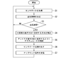
- FIG. 4 is a flow chart showing the operation of the terminal station 3 according to the first embodiment.
- the data acquisition unit 371 of the terminal station 3 acquires the sensor data detected by the sensor group 33, and writes the acquired sensor data in the data storage unit 372 (step S1).
- the timing determination unit 373 determines the next transmission period based on the orbit information of the LEO satellite and the position of the terminal station 3 (step S2).
- the timing determination unit 373 determines whether or not the current time is included in the transmission period (step S3). That is, the timing determination unit 373 determines whether or not the current time is the signal transmission timing.
- step S3 If the current time is not included in the transmission period (step S3: NO), the process returns to step S1 and the acquisition of sensor data is continued.
- the direction specifying unit 374 specifies a direction orthogonal to the traveling direction of the water surface wave based on the data stored in the data storage unit 372 (step S4). ..
- the rotation control unit 375 outputs a signal for controlling the actuator 35 so that the extending direction of the antenna 36 faces in the direction specified by the direction specifying unit 374 (step S5).
- the transmission unit 376 reads out the sensor data from the data storage unit 372 (step S6).
- the transmission unit 376 wirelessly transmits the terminal uplink signal set with the read sensor data from the antenna 36 (step S7). Then, the control device 37 returns the process to step S1.
- the control device 37 rotates the antenna 36 by the actuator 35 and transmits the signal from the antenna 36 during the signal transmission period. That is, the rotation control unit 375 of the control device 37 starts driving the actuator 35 at the transmission timing, and continues driving the actuator 35 until the signal transmission is completed.
- the terminal station 3 can transmit the signal while maintaining the state in which the extending direction of the antenna 36 is orthogonal to the traveling direction of the water surface wave. By maintaining a state in which the extending direction of the antenna 36 is orthogonal to the traveling direction of the water surface wave, the transmission intensity of the signal in the vertical direction upward can be maintained. The reason will be explained below.
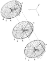
- FIG. 5 is a diagram showing an example of a change in the directivity pattern when the extending direction of the antenna 36 is maintained orthogonal to the traveling direction of the water surface wave.
- the vertical direction is referred to as the Z-axis direction
- the horizontal direction in which the water surface wave travels is referred to as the X-axis direction
- the direction orthogonal to the X-axis is referred to as the Z-axis direction.
- the extending direction of the antenna 36 is orthogonal to the traveling direction of the water surface wave. That is, the extending direction of the antenna 36 faces the Y-axis direction.
- the antenna 36 is an antenna having a donut-shaped directivity pattern such as a dipole antenna or a monopole antenna, the directivity pattern P is rotationally symmetric with respect to the extending direction of the antenna 36. Therefore, the directivity pattern P is maintained even if the antenna 36 is rotated around the Y axis orthogonal to the traveling direction of the water surface wave due to the water surface wave. That is, it is possible to prevent the signal strength Px from fluctuating upward in the vertical direction.
- FIG. 6 is a diagram showing an example of a change in the directivity pattern when the extending direction of the antenna 36 is not orthogonal to the traveling direction of the water surface wave.
- the extending direction of the antenna 36 faces the traveling direction of the water surface wave. That is, the extending direction of the antenna 36 faces the X-axis direction. Since the directional pattern P of the antenna 36 is rotationally symmetric with respect to the extending direction of the antenna 36, when the antenna 36 is rotated about the Y axis by the water surface wave, the directional pattern P is axially orthogonal to the axis of rotational symmetry. Rotate to. Therefore, when the extending direction of the antenna 36 is not orthogonal to the traveling direction of the water surface wave, the larger the inclination with respect to the horizontal plane, the smaller the signal strength Px in the vertical direction.
- the control device 37 includes a processor, a memory, an auxiliary storage device, etc. connected by a bus, and by executing a communication program, a data acquisition unit 371, a data storage unit 372, a timing determination unit 373, a direction specifying unit 374, and rotation control. It functions as a device including a unit 375 and a transmission unit 376.
- the processor include a CPU (Central Processing Unit), a GPU (Graphic Processing Unit), a microprocessor and the like.
- the communication program may be recorded on a computer-readable recording medium.
- the computer-readable recording medium is, for example, a storage device such as a magnetic disk, a magneto-optical disk, an optical disk, or a semiconductor memory.
- the communication program may be transmitted over a telecommunication line. All or part of each function of the control device 37 may be realized by using a custom LSI (Large Scale Integrated Circuit) such as an ASIC (Application Specific Integrated Circuit) or a PLD (Programmable Logic Device). Examples of PLDs include PAL (Programmable Array Logic), GAL (Generic Array Logic), CPLD (Complex Programmable Logic Device), and FPGA (Field Programmable Gate Array). Such integrated circuits are also included as an example of a processor.
- the control device 37 drives the actuator 35 so that the direction in which the change in the inclination of the floating body 31 is the smallest coincides with the extending direction of the antenna 36, as shown in FIG. It is possible to maintain a state in which the extending direction of the antenna 36 is orthogonal to the traveling direction of the water surface wave. Therefore, the terminal station 3 can maintain the direction of the directivity of the antenna 36 with a simple configuration in which the number of rotation axes X to be controlled is small.
- the wireless communication device is the terminal station 3.
- the wireless communication device according to another embodiment may be the base station 4.
- the terminal station 3 includes one actuator 35 that rotates the antenna 36 around a rotation axis X orthogonal to the extending direction of the antenna 36.
- the terminal station 3 according to another embodiment may further include another actuator that rotates the antenna 36 around a rotation axis orthogonal to the extension direction of the rotation axis X and the antenna 36.
- the control device 37 drives another actuator, so that all the shaking with respect to the horizontal plane can be suppressed.
- the antenna 36 Since the wave traveling in the direction orthogonal to the main traveling direction is sufficiently smaller than the wave traveling in the main traveling direction, the antenna 36 is rotated with respect to one rotation axis X as in the above-described embodiment. Even so, the direction of directivity can be sufficiently maintained.
- the terminal station 3 provided on the ground may not have a configuration that rotatably supports the antenna 36.
- Wireless communication system 2 ... Mobile relay station 3 ... Terminal station 31 ... Floating body 32 ... Housing 33 ... Sensor group 34 ... Support unit 35 ... Actuator 36 ... Antenna 37 ... Control device 371 ... Data acquisition unit 372 ... Data storage unit 373 ... Timing determination unit 374 ... Direction identification unit 375 ... Rotation control unit 376 ... Transmission unit 4 ... Base station X ... Rotation axis
Landscapes
- Variable-Direction Aerials And Aerial Arrays (AREA)
- Mobile Radio Communication Systems (AREA)
- Details Of Aerials (AREA)
- Support Of Aerials (AREA)
Abstract
Description
本発明の目的は、簡易な構成でアンテナの指向性の方向を維持することができる無線通信装置及び制御方法を提供することにある。
図1は、第1の実施形態による無線通信システム1の構成図である。無線通信システム1は、移動中継局2と、端末局3と、基地局4とを有する。無線通信システム1が有する移動中継局2、端末局3及び基地局4それぞれの数は任意であるが、端末局3の数は多数であることが想定される。
図4は、第1の実施形態による端末局3の動作を示すフロー図である。端末局3のデータ取得部371は、センサ群33が検出したセンサデータを取得し、取得したセンサデータをデータ記憶部372に書き込む(ステップS1)。タイミング決定部373は、LEO衛星の軌道情報と端末局3の位置とに基づいて、次回の送信期間を決定する(ステップS2)。タイミング決定部373は、現在時刻が送信期間に含まれるか否かを判定する(ステップS3)。すなわち、タイミング決定部373は、現在時刻が信号の送信タイミングであるか否かを判定する。
制御装置37は、バスで接続されたプロセッサ、メモリ、補助記憶装置などを備え、通信プログラムを実行することによってデータ取得部371、データ記憶部372、タイミング決定部373、方向特定部374、回転制御部375及び送信部376を備える装置として機能する。プロセッサの例としては、CPU(Central Processing Unit)、GPU(Graphic Processing Unit)、マイクロプロセッサなどが挙げられる。
通信プログラムは、コンピュータ読み取り可能な記録媒体に記録されてもよい。コンピュータ読み取り可能な記録媒体とは、例えば磁気ディスク、光磁気ディスク、光ディスク、半導体メモリ等の記憶装置である。通信プログラムは、電気通信回線を介して送信されてもよい。
なお、制御装置37の各機能の全て又は一部は、ASIC(Application Specific Integrated Circuit)やPLD(Programmable Logic Device)等のカスタムLSI(Large Scale Integrated Circuit)を用いて実現されてもよい。PLDの例としては、PAL(Programmable Array Logic)、GAL(Generic Array Logic)、CPLD(Complex Programmable Logic Device)、FPGA(Field Programmable Gate Array)が挙げられる。このような集積回路も、プロセッサの一例に含まれる。
Claims (5)
- 棒状のエレメントを有するアンテナと、
前記アンテナを、前記エレメントの延在方向に直交する回転軸回りに回転可能に支持する支持部と、
前記アンテナを前記回転軸回りに回転させるアクチュエータと、
前記支持部を支持し、水に浮く浮体と、
前記支持部の傾きに係る物理量を計測するセンサと、
制御装置と
を備え、
前記制御装置は、
前記センサの計測値を取得する計測値取得部と、
前記計測値に基づいて、傾きの変化が最も小さい方向と前記アンテナの延在方向とが一致するように前記アクチュエータを駆動させる回転制御部と
を備える無線通信装置。 - 前記支持部は、前記浮体が波のない水面に浮くときに前記アンテナの延在方向が水平になるように前記アンテナを支持する
請求項1に記載の無線通信装置。 - 前記制御装置は、
信号の送信タイミングを決定するタイミング決定部と、
前記送信タイミングに前記信号を送信する送信部と
を備え、
前記回転制御部は、前記送信タイミングに前記アクチュエータを駆動させる
請求項1又は請求項2に記載の無線通信装置。 - 前記回転制御部は、前記信号の送信が完了するまで前記アクチュエータを駆動させる
請求項3に記載の無線通信装置。 - 棒状のエレメントを有するアンテナと、
前記アンテナを、前記アンテナの延在方向に直交する回転軸回りに回転可能に支持する支持部と、
前記回転軸回りに前記アンテナを回転させるアクチュエータと、
前記支持部を支持し、水に浮く浮体と、
前記支持部の傾きに係る物理量を計測するセンサと、
を備える無線通信装置の制御方法であって、
前記センサの計測値を取得するステップと、
前記計測値が示す傾きの変化が最も小さい方向と前記アンテナの延在方向とが一致するように前記アクチュエータを駆動させるステップと
を有する制御方法。
Priority Applications (3)
| Application Number | Priority Date | Filing Date | Title |
|---|---|---|---|
| PCT/JP2020/048475 WO2022137441A1 (ja) | 2020-12-24 | 2020-12-24 | 無線通信装置及び制御方法 |
| JP2022570892A JP7538442B2 (ja) | 2020-12-24 | 2020-12-24 | 無線通信装置及び制御方法 |
| US18/267,316 US12444836B2 (en) | 2020-12-24 | 2020-12-24 | Wireless communication apparatus and control method |
Applications Claiming Priority (1)
| Application Number | Priority Date | Filing Date | Title |
|---|---|---|---|
| PCT/JP2020/048475 WO2022137441A1 (ja) | 2020-12-24 | 2020-12-24 | 無線通信装置及び制御方法 |
Publications (1)
| Publication Number | Publication Date |
|---|---|
| WO2022137441A1 true WO2022137441A1 (ja) | 2022-06-30 |
Family
ID=82159256
Family Applications (1)
| Application Number | Title | Priority Date | Filing Date |
|---|---|---|---|
| PCT/JP2020/048475 Ceased WO2022137441A1 (ja) | 2020-12-24 | 2020-12-24 | 無線通信装置及び制御方法 |
Country Status (3)
| Country | Link |
|---|---|
| US (1) | US12444836B2 (ja) |
| JP (1) | JP7538442B2 (ja) |
| WO (1) | WO2022137441A1 (ja) |
Families Citing this family (1)
| Publication number | Priority date | Publication date | Assignee | Title |
|---|---|---|---|---|
| KR102252062B1 (ko) * | 2019-12-31 | 2021-05-14 | 한국항공우주연구원 | 안테나의 구동을 최적화하는 방법, 장치 및 컴퓨터 프로그램 |
Citations (4)
| Publication number | Priority date | Publication date | Assignee | Title |
|---|---|---|---|---|
| JPS58101506A (ja) * | 1981-12-14 | 1983-06-16 | Nippon Telegr & Teleph Corp <Ntt> | 移動体搭載装置用簡易動揺補償装置 |
| JP2000038188A (ja) * | 1998-07-23 | 2000-02-08 | Toyo Commun Equip Co Ltd | 自機位置情報送信浮標 |
| JP2008157642A (ja) * | 2006-12-21 | 2008-07-10 | Hitachi Zosen Corp | 津波・波浪観測用ブイ |
| JP2015014472A (ja) * | 2013-07-03 | 2015-01-22 | 古野電気株式会社 | エコー信号処理装置、波浪レーダ装置、エコー信号処理方法、及びエコー信号処理プログラム |
Family Cites Families (38)
| Publication number | Priority date | Publication date | Assignee | Title |
|---|---|---|---|---|
| US4596989A (en) * | 1983-02-14 | 1986-06-24 | Tracor Bei, Inc. | Stabilized antenna system having an acceleration displaceable mass |
| US4920350A (en) * | 1984-02-17 | 1990-04-24 | Comsat Telesystems, Inc. | Satellite tracking antenna system |
| US5517204A (en) * | 1992-03-10 | 1996-05-14 | Tokimec Inc. | Antenna directing apparatus |
| US5383363A (en) * | 1993-02-10 | 1995-01-24 | Ford Motor Company | Inertial measurement unit providing linear and angular outputs using only fixed linear accelerometer sensors |
| US6023247A (en) * | 1997-02-19 | 2000-02-08 | Winegard Company | Satellite dish antenna stabilizer platform |
| WO2000003263A2 (en) * | 1998-07-06 | 2000-01-20 | Alliedsignal Inc. | Method and apparatus for implementing automatic tilt control of a radar antenna on an aircraft |
| GB2368218B (en) * | 2000-06-01 | 2004-04-28 | Furuno Electric Co | System for determining the heading and/or attitude of a body |
| US6621460B2 (en) * | 2001-05-21 | 2003-09-16 | The Boeing Company | Instrument alignment devices and methods |
| US6917337B2 (en) * | 2002-06-05 | 2005-07-12 | Fujitsu Limited | Adaptive antenna unit for mobile terminal |
| US6911949B2 (en) * | 2002-10-21 | 2005-06-28 | Orbit Communication Ltd. | Antenna stabilization system for two antennas |
| US7427962B2 (en) * | 2003-06-16 | 2008-09-23 | Andrew Corporation | Base station antenna rotation mechanism |
| US7432868B2 (en) * | 2004-04-26 | 2008-10-07 | Spencer Webb | Portable antenna positioner apparatus and method |
| US7109937B2 (en) * | 2004-11-29 | 2006-09-19 | Elta Systems Ltd. | Phased array planar antenna and a method thereof |
| US7256734B2 (en) * | 2005-08-29 | 2007-08-14 | The Boeing Company | Spot beam antenna boresight calibration using GPS receivers |
| JP5118816B2 (ja) * | 2006-03-28 | 2013-01-16 | 京セラ株式会社 | 基地局装置及び基地局装置の設置誤り検出方法 |
| EP1986016A1 (en) * | 2007-04-25 | 2008-10-29 | Saab Ab | Device and method for controlling a satellite tracking antenna |
| WO2010040237A1 (de) * | 2008-10-10 | 2010-04-15 | Thales Suisse Sa | Stabilisierung eines mastes für fahrzeuge und schiffe |
| US8542156B2 (en) * | 2008-12-15 | 2013-09-24 | Sea Tel, Inc. | Pedestal for tracking antenna |
| US20110021166A1 (en) * | 2009-07-22 | 2011-01-27 | John Walley | Method and system for antenna diversity with global navigation satellite systems (gnss) |
| WO2011056107A1 (en) * | 2009-11-06 | 2011-05-12 | Saab Ab | Radar system and method for detecting and tracking a target |
| US8330651B2 (en) * | 2009-11-23 | 2012-12-11 | Honeywell International Inc. | Single-antenna FM/CW marine radar |
| WO2011123726A2 (en) * | 2010-03-31 | 2011-10-06 | Linear Signal, Inc. | Apparatus and system for a double gimbal stabilization platform |
| US8648748B2 (en) * | 2010-06-14 | 2014-02-11 | Orbit Communication Ltd. | Effective marine stabilized antenna system |
| US9000995B2 (en) * | 2010-06-27 | 2015-04-07 | Sea Tel, Inc. | Three-axis pedestal having motion platform and piggy back assemblies |
| EP2786175B1 (en) * | 2011-11-29 | 2016-07-27 | AXYS Technologies | Motion-stabilised lidar and method for wind speed measurement |
| DK177464B1 (en) * | 2011-12-08 | 2013-06-24 | Spacecom Holding Aps | Pedestal for tracking antenna |
| US10031220B2 (en) * | 2012-09-20 | 2018-07-24 | Furuno Electric Co., Ltd. | Ship radar apparatus and method of measuring velocity |
| EP2883272B1 (en) * | 2013-08-27 | 2016-06-15 | CommScope Technologies LLC | Alignment determination for antennas and such |
| CN105934852B (zh) * | 2014-01-17 | 2018-11-06 | 三菱电机株式会社 | 天线控制装置及天线装置 |
| CN105940320B (zh) * | 2014-02-21 | 2020-01-07 | 古野电气株式会社 | 结构物的位移检测装置、结构物的位移的共有系统、结构物的位移检测方法、以及结构物的位移检测系统 |
| US9893417B2 (en) * | 2015-01-29 | 2018-02-13 | Speedcast International Limited | Satellite communications terminal for a ship and associated methods |
| JP6211745B1 (ja) * | 2016-01-25 | 2017-10-11 | スカパーJsat株式会社 | アンテナ調整装置およびアンテナ調整方法 |
| JP6392259B2 (ja) * | 2016-02-01 | 2018-09-19 | 株式会社東芝 | 平面アンテナ装置 |
| US10446905B2 (en) * | 2016-02-09 | 2019-10-15 | Amrita Vishwa Vidyapeetham | Automatic antenna orientation and stabilization system and method |
| JP6581144B2 (ja) * | 2017-04-28 | 2019-09-25 | 株式会社東芝 | 衛星捕捉装置および衛星捕捉方法 |
| ES2950580T3 (es) * | 2017-12-22 | 2023-10-11 | Thales Nederland Bv | Disposición de antena integrada |
| WO2019243556A1 (en) * | 2018-06-20 | 2019-12-26 | Overhorizon Ab | Personal on-the-move satellite communications terminal |
| CN112993517B (zh) * | 2019-12-16 | 2024-03-29 | 株式会社东芝 | 卫星捕捉装置以及卫星捕捉方法 |
-
2020
- 2020-12-24 WO PCT/JP2020/048475 patent/WO2022137441A1/ja not_active Ceased
- 2020-12-24 US US18/267,316 patent/US12444836B2/en active Active
- 2020-12-24 JP JP2022570892A patent/JP7538442B2/ja active Active
Patent Citations (4)
| Publication number | Priority date | Publication date | Assignee | Title |
|---|---|---|---|---|
| JPS58101506A (ja) * | 1981-12-14 | 1983-06-16 | Nippon Telegr & Teleph Corp <Ntt> | 移動体搭載装置用簡易動揺補償装置 |
| JP2000038188A (ja) * | 1998-07-23 | 2000-02-08 | Toyo Commun Equip Co Ltd | 自機位置情報送信浮標 |
| JP2008157642A (ja) * | 2006-12-21 | 2008-07-10 | Hitachi Zosen Corp | 津波・波浪観測用ブイ |
| JP2015014472A (ja) * | 2013-07-03 | 2015-01-22 | 古野電気株式会社 | エコー信号処理装置、波浪レーダ装置、エコー信号処理方法、及びエコー信号処理プログラム |
Also Published As
| Publication number | Publication date |
|---|---|
| US20240055757A1 (en) | 2024-02-15 |
| JPWO2022137441A1 (ja) | 2022-06-30 |
| US12444836B2 (en) | 2025-10-14 |
| JP7538442B2 (ja) | 2024-08-22 |
Similar Documents
| Publication | Publication Date | Title |
|---|---|---|
| US6016120A (en) | Method and apparatus for automatically aiming an antenna to a distant location | |
| US6377211B1 (en) | Apparatus and method for pointing a directional device from a moving vehicle toward a spacecraft | |
| US20210258067A1 (en) | Service link antenna configuration and beam forming control in haps | |
| US20170168481A1 (en) | User interface for orienting antennas | |
| EP1882312B1 (en) | Portable antenna positioner apparatus and method | |
| CN106104918A (zh) | 用于空中交通工具的机械操纵且水平极化天线以及相关系统和方法 | |
| WO2019012894A1 (ja) | 3次元対応指向性光アンテナ | |
| JP2019121967A (ja) | 追尾アンテナ、飛翔体、追尾アンテナ装置 | |
| JP7564467B2 (ja) | 信号処理装置、無線通信システムおよび信号処理方法 | |
| US20170033455A1 (en) | Active Interference Avoidance in Unlicensed Bands | |
| CN108886392A (zh) | 天线选择方法和电子设备 | |
| JP7089556B2 (ja) | Hapsのサービスリンクにおけるアンテナ取付プレートからの反射波干渉抑制 | |
| JP7538442B2 (ja) | 無線通信装置及び制御方法 | |
| ES2306390T3 (es) | Calibracion del eje optico de una antena direccional de un satelite gps utilizando receptores gps moviles. | |
| US20040019415A1 (en) | Stratospheric flying object | |
| EP2951881B1 (en) | Polarization alignment for wireless networking systems | |
| CN110970731A (zh) | 调节装置、天线及通信设备 | |
| US7466627B2 (en) | System and method for wireless data collection from seismic recording buoys | |
| JP7477792B2 (ja) | アンテナ方向決定方法、無線通信システム及び通信装置 | |
| JP4494819B2 (ja) | 宇宙通信転送衛星 | |
| CN115242296A (zh) | 一种位置传感器辅助的卫星通讯终端 | |
| JP5206036B2 (ja) | 計測システムおよびブイ | |
| JP3584282B2 (ja) | 円環状セルを用いた無線通信システム | |
| JP2007106269A (ja) | 無人ヘリコプタ | |
| EP4040688B1 (en) | System, communication device, program, and control method |
Legal Events
| Date | Code | Title | Description |
|---|---|---|---|
| 121 | Ep: the epo has been informed by wipo that ep was designated in this application |
Ref document number: 20966930 Country of ref document: EP Kind code of ref document: A1 |
|
| ENP | Entry into the national phase |
Ref document number: 2022570892 Country of ref document: JP Kind code of ref document: A |
|
| WWE | Wipo information: entry into national phase |
Ref document number: 18267316 Country of ref document: US |
|
| NENP | Non-entry into the national phase |
Ref country code: DE |
|
| 122 | Ep: pct application non-entry in european phase |
Ref document number: 20966930 Country of ref document: EP Kind code of ref document: A1 |
|
| WWG | Wipo information: grant in national office |
Ref document number: 18267316 Country of ref document: US |