WO2022137401A1 - 荷電粒子ビーム装置 - Google Patents
荷電粒子ビーム装置 Download PDFInfo
- Publication number
- WO2022137401A1 WO2022137401A1 PCT/JP2020/048255 JP2020048255W WO2022137401A1 WO 2022137401 A1 WO2022137401 A1 WO 2022137401A1 JP 2020048255 W JP2020048255 W JP 2020048255W WO 2022137401 A1 WO2022137401 A1 WO 2022137401A1
- Authority
- WO
- WIPO (PCT)
- Prior art keywords
- sample
- sample piece
- charged particle
- particle beam
- image
- Prior art date
Links
- 239000002245 particle Substances 0.000 title claims abstract description 144
- 230000003287 optical effect Effects 0.000 claims abstract description 46
- 230000001678 irradiating effect Effects 0.000 claims abstract description 29
- 238000000034 method Methods 0.000 claims description 106
- 230000008569 process Effects 0.000 claims description 94
- 238000012545 processing Methods 0.000 claims description 92
- 230000000052 comparative effect Effects 0.000 claims description 54
- 230000000873 masking effect Effects 0.000 claims description 49
- 230000002093 peripheral effect Effects 0.000 claims description 21
- 230000008021 deposition Effects 0.000 claims description 19
- 238000003860 storage Methods 0.000 claims description 14
- 239000000284 extract Substances 0.000 claims description 8
- 238000012546 transfer Methods 0.000 claims description 6
- 238000003709 image segmentation Methods 0.000 claims description 5
- 238000010884 ion-beam technique Methods 0.000 description 68
- 238000010894 electron beam technology Methods 0.000 description 45
- 230000007246 mechanism Effects 0.000 description 34
- 238000010586 diagram Methods 0.000 description 28
- 238000000605 extraction Methods 0.000 description 28
- 238000010521 absorption reaction Methods 0.000 description 18
- 238000000151 deposition Methods 0.000 description 18
- 150000002500 ions Chemical class 0.000 description 16
- 238000013459 approach Methods 0.000 description 15
- 239000010408 film Substances 0.000 description 14
- 238000002360 preparation method Methods 0.000 description 12
- 238000003754 machining Methods 0.000 description 10
- 238000005520 cutting process Methods 0.000 description 8
- 230000005540 biological transmission Effects 0.000 description 6
- 230000000694 effects Effects 0.000 description 6
- BASFCYQUMIYNBI-UHFFFAOYSA-N platinum Chemical compound [Pt] BASFCYQUMIYNBI-UHFFFAOYSA-N 0.000 description 6
- 239000004065 semiconductor Substances 0.000 description 6
- 238000005530 etching Methods 0.000 description 5
- 230000002950 deficient Effects 0.000 description 4
- 238000005070 sampling Methods 0.000 description 4
- 230000000007 visual effect Effects 0.000 description 4
- 238000004458 analytical method Methods 0.000 description 3
- 239000002131 composite material Substances 0.000 description 3
- 230000007547 defect Effects 0.000 description 3
- 238000009826 distribution Methods 0.000 description 3
- 230000006870 function Effects 0.000 description 3
- 229910052697 platinum Inorganic materials 0.000 description 3
- 238000000926 separation method Methods 0.000 description 3
- 238000004544 sputter deposition Methods 0.000 description 3
- OKTJSMMVPCPJKN-UHFFFAOYSA-N Carbon Chemical compound [C] OKTJSMMVPCPJKN-UHFFFAOYSA-N 0.000 description 2
- UFWIBTONFRDIAS-UHFFFAOYSA-N Naphthalene Chemical compound C1=CC=CC2=CC=CC=C21 UFWIBTONFRDIAS-UHFFFAOYSA-N 0.000 description 2
- XUIMIQQOPSSXEZ-UHFFFAOYSA-N Silicon Chemical compound [Si] XUIMIQQOPSSXEZ-UHFFFAOYSA-N 0.000 description 2
- 238000013473 artificial intelligence Methods 0.000 description 2
- 230000008901 benefit Effects 0.000 description 2
- 230000015572 biosynthetic process Effects 0.000 description 2
- 229910052799 carbon Inorganic materials 0.000 description 2
- 238000013461 design Methods 0.000 description 2
- 238000001514 detection method Methods 0.000 description 2
- 238000007730 finishing process Methods 0.000 description 2
- 229910052751 metal Inorganic materials 0.000 description 2
- 239000002184 metal Substances 0.000 description 2
- 238000012986 modification Methods 0.000 description 2
- 230000004048 modification Effects 0.000 description 2
- YNPNZTXNASCQKK-UHFFFAOYSA-N phenanthrene Chemical compound C1=CC=C2C3=CC=CC=C3C=CC2=C1 YNPNZTXNASCQKK-UHFFFAOYSA-N 0.000 description 2
- 230000003252 repetitive effect Effects 0.000 description 2
- 238000001878 scanning electron micrograph Methods 0.000 description 2
- 229910052710 silicon Inorganic materials 0.000 description 2
- 239000010703 silicon Substances 0.000 description 2
- 238000009966 trimming Methods 0.000 description 2
- WFKWXMTUELFFGS-UHFFFAOYSA-N tungsten Chemical compound [W] WFKWXMTUELFFGS-UHFFFAOYSA-N 0.000 description 2
- 229910052721 tungsten Inorganic materials 0.000 description 2
- 239000010937 tungsten Substances 0.000 description 2
- BLIQUJLAJXRXSG-UHFFFAOYSA-N 1-benzyl-3-(trifluoromethyl)pyrrolidin-1-ium-3-carboxylate Chemical compound C1C(C(=O)O)(C(F)(F)F)CCN1CC1=CC=CC=C1 BLIQUJLAJXRXSG-UHFFFAOYSA-N 0.000 description 1
- GYHNNYVSQQEPJS-UHFFFAOYSA-N Gallium Chemical compound [Ga] GYHNNYVSQQEPJS-UHFFFAOYSA-N 0.000 description 1
- 230000001133 acceleration Effects 0.000 description 1
- 239000000853 adhesive Substances 0.000 description 1
- 230000001070 adhesive effect Effects 0.000 description 1
- 238000009412 basement excavation Methods 0.000 description 1
- 238000007630 basic procedure Methods 0.000 description 1
- FQNHWXHRAUXLFU-UHFFFAOYSA-N carbon monoxide;tungsten Chemical group [W].[O+]#[C-].[O+]#[C-].[O+]#[C-].[O+]#[C-].[O+]#[C-].[O+]#[C-] FQNHWXHRAUXLFU-UHFFFAOYSA-N 0.000 description 1
- 230000008859 change Effects 0.000 description 1
- 238000004140 cleaning Methods 0.000 description 1
- 238000012790 confirmation Methods 0.000 description 1
- 239000000470 constituent Substances 0.000 description 1
- 238000012937 correction Methods 0.000 description 1
- 230000007423 decrease Effects 0.000 description 1
- 238000011161 development Methods 0.000 description 1
- 230000018109 developmental process Effects 0.000 description 1
- 230000005684 electric field Effects 0.000 description 1
- -1 ethylcyclopentadienyl Chemical group 0.000 description 1
- 229910052733 gallium Inorganic materials 0.000 description 1
- 238000002347 injection Methods 0.000 description 1
- 239000007924 injection Substances 0.000 description 1
- 239000012212 insulator Substances 0.000 description 1
- 238000011835 investigation Methods 0.000 description 1
- 239000007788 liquid Substances 0.000 description 1
- 229910001338 liquidmetal Inorganic materials 0.000 description 1
- 238000004519 manufacturing process Methods 0.000 description 1
- 239000000463 material Substances 0.000 description 1
- 238000005259 measurement Methods 0.000 description 1
- 239000000203 mixture Substances 0.000 description 1
- 230000000737 periodic effect Effects 0.000 description 1
- 238000003672 processing method Methods 0.000 description 1
- 230000001737 promoting effect Effects 0.000 description 1
- 230000009467 reduction Effects 0.000 description 1
- 230000004044 response Effects 0.000 description 1
- 239000007787 solid Substances 0.000 description 1
- 239000010409 thin film Substances 0.000 description 1
- XLYOFNOQVPJJNP-UHFFFAOYSA-N water Chemical compound O XLYOFNOQVPJJNP-UHFFFAOYSA-N 0.000 description 1
Images


Classifications
-
- H—ELECTRICITY
- H01—ELECTRIC ELEMENTS
- H01J—ELECTRIC DISCHARGE TUBES OR DISCHARGE LAMPS
- H01J37/00—Discharge tubes with provision for introducing objects or material to be exposed to the discharge, e.g. for the purpose of examination or processing thereof
- H01J37/30—Electron-beam or ion-beam tubes for localised treatment of objects
- H01J37/31—Electron-beam or ion-beam tubes for localised treatment of objects for cutting or drilling
-
- H—ELECTRICITY
- H01—ELECTRIC ELEMENTS
- H01J—ELECTRIC DISCHARGE TUBES OR DISCHARGE LAMPS
- H01J37/00—Discharge tubes with provision for introducing objects or material to be exposed to the discharge, e.g. for the purpose of examination or processing thereof
- H01J37/02—Details
- H01J37/20—Means for supporting or positioning the objects or the material; Means for adjusting diaphragms or lenses associated with the support
-
- G—PHYSICS
- G01—MEASURING; TESTING
- G01N—INVESTIGATING OR ANALYSING MATERIALS BY DETERMINING THEIR CHEMICAL OR PHYSICAL PROPERTIES
- G01N1/00—Sampling; Preparing specimens for investigation
- G01N1/28—Preparing specimens for investigation including physical details of (bio-)chemical methods covered elsewhere, e.g. G01N33/50, C12Q
- G01N1/286—Preparing specimens for investigation including physical details of (bio-)chemical methods covered elsewhere, e.g. G01N33/50, C12Q involving mechanical work, e.g. chopping, disintegrating, compacting, homogenising
-
- G—PHYSICS
- G06—COMPUTING; CALCULATING OR COUNTING
- G06T—IMAGE DATA PROCESSING OR GENERATION, IN GENERAL
- G06T7/00—Image analysis
-
- H—ELECTRICITY
- H01—ELECTRIC ELEMENTS
- H01J—ELECTRIC DISCHARGE TUBES OR DISCHARGE LAMPS
- H01J37/00—Discharge tubes with provision for introducing objects or material to be exposed to the discharge, e.g. for the purpose of examination or processing thereof
- H01J37/26—Electron or ion microscopes; Electron or ion diffraction tubes
- H01J37/28—Electron or ion microscopes; Electron or ion diffraction tubes with scanning beams
-
- H—ELECTRICITY
- H01—ELECTRIC ELEMENTS
- H01J—ELECTRIC DISCHARGE TUBES OR DISCHARGE LAMPS
- H01J37/00—Discharge tubes with provision for introducing objects or material to be exposed to the discharge, e.g. for the purpose of examination or processing thereof
- H01J37/30—Electron-beam or ion-beam tubes for localised treatment of objects
- H01J37/304—Controlling tubes by information coming from the objects or from the beam, e.g. correction signals
- H01J37/3045—Object or beam position registration
-
- H—ELECTRICITY
- H01—ELECTRIC ELEMENTS
- H01J—ELECTRIC DISCHARGE TUBES OR DISCHARGE LAMPS
- H01J37/00—Discharge tubes with provision for introducing objects or material to be exposed to the discharge, e.g. for the purpose of examination or processing thereof
- H01J37/30—Electron-beam or ion-beam tubes for localised treatment of objects
- H01J37/305—Electron-beam or ion-beam tubes for localised treatment of objects for casting, melting, evaporating or etching
- H01J37/3053—Electron-beam or ion-beam tubes for localised treatment of objects for casting, melting, evaporating or etching for evaporating or etching
- H01J37/3056—Electron-beam or ion-beam tubes for localised treatment of objects for casting, melting, evaporating or etching for evaporating or etching for microworking, e.g. etching of gratings, trimming of electrical components
-
- G—PHYSICS
- G01—MEASURING; TESTING
- G01N—INVESTIGATING OR ANALYSING MATERIALS BY DETERMINING THEIR CHEMICAL OR PHYSICAL PROPERTIES
- G01N1/00—Sampling; Preparing specimens for investigation
- G01N1/28—Preparing specimens for investigation including physical details of (bio-)chemical methods covered elsewhere, e.g. G01N33/50, C12Q
- G01N1/286—Preparing specimens for investigation including physical details of (bio-)chemical methods covered elsewhere, e.g. G01N33/50, C12Q involving mechanical work, e.g. chopping, disintegrating, compacting, homogenising
- G01N2001/2873—Cutting or cleaving
-
- H—ELECTRICITY
- H01—ELECTRIC ELEMENTS
- H01J—ELECTRIC DISCHARGE TUBES OR DISCHARGE LAMPS
- H01J2237/00—Discharge tubes exposing object to beam, e.g. for analysis treatment, etching, imaging
- H01J2237/20—Positioning, supporting, modifying or maintaining the physical state of objects being observed or treated
- H01J2237/208—Elements or methods for movement independent of sample stage for influencing or moving or contacting or transferring the sample or parts thereof, e.g. prober needles or transfer needles in FIB/SEM systems
-
- H—ELECTRICITY
- H01—ELECTRIC ELEMENTS
- H01J—ELECTRIC DISCHARGE TUBES OR DISCHARGE LAMPS
- H01J2237/00—Discharge tubes exposing object to beam, e.g. for analysis treatment, etching, imaging
- H01J2237/30—Electron or ion beam tubes for processing objects
- H01J2237/317—Processing objects on a microscale
- H01J2237/3174—Etching microareas
- H01J2237/31745—Etching microareas for preparing specimen to be viewed in microscopes or analyzed in microanalysers
-
- H—ELECTRICITY
- H01—ELECTRIC ELEMENTS
- H01J—ELECTRIC DISCHARGE TUBES OR DISCHARGE LAMPS
- H01J2237/00—Discharge tubes exposing object to beam, e.g. for analysis treatment, etching, imaging
- H01J2237/30—Electron or ion beam tubes for processing objects
- H01J2237/317—Processing objects on a microscale
- H01J2237/31749—Focused ion beam
Definitions
- the present invention relates to a charged particle beam device having a sample extraction function.
- Focused ion beam (FIB) method which is one of the processing methods using a charged particle beam device, is fine processing using the sputtering phenomenon of target constituent atoms by irradiating a sample with a focused ion beam. It is a law.
- a FIB-SEM composite device that combines a FIB device and a scanning electron microscope (SEM) has been commercialized.
- SEM scanning electron microscope
- FIB-SEM composite devices in the semiconductor field include, for example, structural observation in device development and defect analysis, dimensional measurement, and investigation / confirmation of product reproducibility and reliability.
- processing and observation at a plurality of locations in the semiconductor wafer or semiconductor device are indispensable, the device is required to shorten the working time, save labor and reduce skills.
- Patent Document 1 discloses a technique for extracting a target portion in a sample with fully automatic or equivalent performance and fixing it to a sample piece holder for processing.
- a process of accurately recognizing a target location, processing and extracting the sample to an appropriate size, and then fixing the sample in a desired position is performed.
- Patent Document 2 the detection of contact / separation between the sample piece and the needle for extracting the sample piece, and the contact / separation between the extracted sample piece and the sample piece holder to which the sample piece is attached is executed by measuring the electrical continuity. Disclosed is a technique for advancing the extraction operation of a sample piece by controlling the process according to the processing time when continuity cannot be obtained.
- sample pieces have been automatically extracted using SIM (Scanning Ion Microscope) images, SEM images, their absorption current images, various image processing techniques, and the like.
- SIM Surface Ion Microscope
- SEM Surface Electrometic Electrode
- the target sample is a semiconductor wafer or a semiconductor device
- the accuracy and stability of automatic extraction of the sample piece depend on the structure of the sample as the device structure becomes finer and more diversified. There is.
- the present invention has been made in view of the above, and an object of the present invention is to provide a charged particle beam device capable of performing automatic extraction of a sample piece accurately and stably.
- the charged particle beam device automatically extracts a sample piece from a sample.
- the charged particle beam device includes a sample stage on which a sample is placed and moved, a charged particle beam irradiation optical system for irradiating a charged particle beam, and a sample piece moving means for holding and transporting a sample piece extracted from the sample. It is equipped with a holder fixing base for holding the sample piece holder to which the sample piece is transferred, and a computer.
- the computer is obtained by irradiating the reference image obtained by irradiating the sample with the charged particle beam in advance and irradiating the sample to be extracted with the sample piece with the charged particle beam. Select the matching area for image matching with the comparison image.
- the needle is brought closer to the sample piece by performing the following processing as the first step for extracting the sample piece.
- An absorption current image obtained by irradiating the needle with a charged particle beam before automatic extraction of the sample and a reference image previously created from a secondary electron image obtained by irradiating the sample piece with the charged particle beam.
- the position coordinates of the needle tip and the position coordinates of the part of the sample piece to be removed where the needle tip is brought close to are determined by image recognition, and the needle tip is brought close to the determined position coordinates.
- the contrast value, brightness value, scan speed, image size, etc. can be set in advance from the reference image of the sample piece to be acquired.
- a recognition failure occurs such as "a position that is not the needle approaching position is recognized as the needle approaching position"
- the sample or sample piece (there is a risk of contacting not only the sample piece but also the sample) and the needle.
- the sample, sample piece, or needle will be damaged or deformed due to contact with the sample. Damage or deformation of a sample or sample piece is a major problem in handling valuable samples. If the needle is damaged or deformed, it is necessary to replace the needle. In either case, not only the performance is greatly reduced, but also the original purpose of automatic extraction of the sample piece cannot be realized.
- a sample piece automatic extraction sequence is performed by detecting a learned repetitive pattern region in an image using artificial intelligence (AI: Artificial Intelligence) and masking the detected repetitive pattern region. Is made to be able to be executed accurately and stably.
- AI Artificial Intelligence
- FIG. 1 is a configuration diagram showing an example of an automatic sample piece preparation device including the charged particle beam device according to the first embodiment of the present invention.
- the automatic sample piece preparation device 10 includes a charged particle beam device 10a and the like.
- the charged particle beam device 10a includes a sample chamber 11 capable of maintaining the inside in a vacuum state, a stage 12 capable of fixing the sample S and the sample piece holder P inside the sample chamber 11, a stage drive mechanism 13 for driving the stage 12, and the like. I have.
- the charged particle beam device 10a includes a focused ion beam irradiation optical system 14 that irradiates an irradiation target within a predetermined irradiation region (scanning range) inside the sample chamber 11 with a FIB.
- the charged particle beam device 10a includes an electron beam irradiation optical system 15 that irradiates an electron beam (EB) on an irradiation target in a predetermined irradiation region inside the sample chamber 11.
- the charged particle beam device 10a includes a detector 16 that detects secondary charged particles (secondary electrons, secondary ions) R generated from an irradiation target by irradiation with a focused ion beam or an electron beam.
- the charged particle beam device 10a includes a gas supply unit 17 that supplies gas G to the surface of the irradiation target.
- the gas supply unit 17 is composed of a nozzle 17a or the like having an outer diameter of about 200 ⁇ m.
- the charged particle beam device 10a takes out (extracts) a minute sample piece Q from the sample S fixed to the stage 12, holds the taken out sample piece Q, and moves the needle 18 to the sample piece holder P. It is provided with a needle driving mechanism 19 for driving the sample piece Q to convey the sample piece Q.
- the needle 18 and the needle driving mechanism 19 may be collectively referred to as a sample piece transfer means.
- the charged particle beam device 10a includes a display device 20 for displaying image data and the like based on the secondary charged particles R detected by the detector 16, a computer 21, and an input device 22.
- the irradiation targets of the focused ion beam irradiation optical system 14 and the electron beam irradiation optical system 15 include the sample S fixed to the stage 12, the sample piece Q, and the needle 18 and the sample piece holder P existing in the irradiation region. include.
- the charged particle beam device 10a irradiates the surface of the irradiation target with a focused ion beam while scanning the imaged portion, various processing by sputtering (for example, excavation and trimming processing, etc.), and a deposition film. Formation etc. can be performed.
- the charged particle beam device 10a can execute a process of forming a sample piece Q (for example, a thin piece sample, a needle-shaped sample, etc.) for transmission observation by a transmission electron microscope or an analysis sample piece using an electron beam from the sample S. ..
- the charged particle beam device 10a can perform processing to make the sample piece Q transferred to the sample piece holder P into a thin film having a desired thickness (for example, 5 to 100 nm) suitable for transmission observation by a transmission electron microscope. Is.
- the charged particle beam device 10a can observe the surface of the irradiation target by irradiating the surface of the irradiation target such as the sample piece Q and the needle 18 while scanning the focused ion beam or the electron beam.
- the sample chamber 11 is configured so that the inside can be exhausted to a desired vacuum state by an exhaust device (not shown) and the desired vacuum state can be maintained.
- the stage 12 holds the sample S.
- the stage 12 includes a holder fixing base 12a for holding the sample piece holder P.
- the holder fixing base 12a may have a configuration in which a plurality of sample piece holders P can be mounted.
- FIG. 3 is a plan view of the sample piece holder.
- FIG. 4 is a side view of the sample piece holder.
- the sample piece holder P includes a substantially semicircular plate-shaped base portion 32 having a notch portion 31, and a sample table 33 fixed to the notch portion 31.
- the base 32 is formed of, for example, a metal having a circular plate shape having a diameter of 3 mm and a thickness of 50 ⁇ m.
- the sample table 33 is formed from, for example, a silicon wafer by a semiconductor manufacturing process, and is attached to the notch 31 with a conductive adhesive.
- the sample table 33 has a comb-teeth shape, and is a plurality of pieces (for example, 5, 10, 15, 20, etc.) that are spaced apart from each other and project, and a columnar portion (hereinafter, also referred to as a pillar) to which the sample piece Q is transferred. ) 34 is provided.
- each columnar portion 34 By making the width of each columnar portion 34 different, the extraction location of the sample piece Q on the sample S and the image of the sample piece Q and the columnar portion 34 transferred to each columnar portion 34 are associated with each other to further correspond. By storing it in the computer 21 in association with the sample piece holder P, even when a plurality of sample pieces Q are produced from one sample S, each sample piece Q can be recognized without mistake. Subsequent analysis by a transmission electron microscope or the like can be performed without fail in associating the corresponding sample piece Q with the extracted portion on the sample S.
- Each columnar portion 34 is formed, for example, with a tip portion having a thickness of 10 ⁇ m or less and 5 ⁇ m or less, and holds a sample piece Q attached to the tip portion.
- the base portion 32 is not limited to a circular plate shape having a diameter of 3 mm and a thickness of 50 ⁇ m as described above, and may be a rectangular plate shape having a length of 5 mm, a height of 2 mm, a thickness of 50 ⁇ m, or the like. good.
- the shape of the base 32 is a shape that can be mounted on the stage 12 to be introduced into the subsequent transmission electron microscope, and a shape such that all the sample pieces Q mounted on the sample table 33 are located within the movable range of the stage 12. It should be.
- the stage drive mechanism 13 is housed inside the sample chamber 11 in a state of being connected to the stage 12, and displaces the stage 12 with respect to a predetermined axis according to a control signal output from the computer 21.
- the stage drive mechanism 13 includes a moving mechanism 13a that moves the stage 12 in parallel along at least the X-axis and the Y-axis that are parallel to the horizontal plane and orthogonal to each other and the Z-axis in the vertical direction that is orthogonal to the X-axis and the Y-axis.
- the stage drive mechanism 13 includes a tilt mechanism 13b that tilts the stage 12 around the X-axis or the Y-axis, and a rotation mechanism 13c that rotates the stage 12 around the Z-axis.
- the beam emitting portion (not shown) is placed inside the sample chamber 11 at a position above the stage 12 in the vertical direction in the irradiation region, and the optical axis is oriented in the vertical direction. It is fixed to the sample chamber 11 in parallel with the sample chamber 11.
- the focused ion beam irradiation optical system 14 directs the focused ion beam from above to below in the vertical direction to the irradiation target such as the sample S fixed to the stage 12, the sample piece Q, and the needle 18 existing in the irradiation region. Irradiation is possible.
- the focused ion beam irradiation optical system 14 includes an ion source 14a for generating ions and an ion optical system 14b for focusing and deflecting ions drawn from the ion source 14a.
- the ion source 14a and the ion optical system 14b are controlled according to a control signal output from the computer 21, and the irradiation position and irradiation conditions of the focused ion beam are controlled by the computer 21.
- the ion source 14a is, for example, a liquid metal ion source using liquid gallium or the like, a plasma type ion source, a gas electric field ionization type ion source, or the like.
- the ion optical system 14b includes, for example, a first electrostatic lens such as a condenser lens, an electrostatic deflector, a second electrostatic lens such as an objective lens, and the like.
- the beam emitting portion (not shown) is inclined inside the sample chamber 11 by a predetermined angle (for example, 60 °) with respect to the vertical direction of the stage 12 in the irradiation region. It is fixed to the sample chamber 11 with the optical axis parallel to the tilting direction. As a result, it is possible to irradiate the irradiation target such as the sample S fixed to the stage 12, the sample piece Q, and the needle 18 existing in the irradiation region from the upper side to the lower side in the inclination direction with the electron beam.
- a predetermined angle for example, 60 °
- the electron beam irradiation optical system 15 includes an electron source 15a for generating electrons and an electron optical system 15b for focusing and deflecting electrons emitted from the electron source 15a.
- the electron source 15a and the electron optical system 15b are controlled according to a control signal output from the computer 21, and the irradiation position and irradiation conditions of the electron beam are controlled by the computer 21.
- the electro-optical system 15b includes, for example, an electromagnetic lens, a deflector, and the like.
- the arrangement of the electron beam irradiation optical system 15 and the focused ion beam irradiation optical system 14 was exchanged, and the electron beam irradiation optical system 15 was tilted in the vertical direction and the focused ion beam irradiation optical system 14 was tilted by a predetermined angle with respect to the vertical direction. It may be arranged in the inclined direction. Further, both the electron beam irradiation optical system 15 and the focused ion beam irradiation optical system 14 do not have to be arranged in the vertical direction.
- the detector 16 has an intensity of secondary charged particles (secondary electrons and secondary ions) R emitted from the irradiation target when the irradiation target such as the sample S and the needle 18 is irradiated with the focused ion beam or the electron beam. (That is, the amount of the secondary charged particles) is detected, and the information of the detected amount of the secondary charged particles R is output.
- the detector 16 is arranged inside the sample chamber 11 at a position where the amount of the secondary charged particles R can be detected, for example, a position diagonally above the irradiation target such as the sample S in the irradiation region, and the sample chamber 11 It is fixed to.
- the gas supply unit 17 is fixed to the sample chamber 11.
- the gas supply unit 17 has a gas injection unit (also referred to as a nozzle) inside the sample chamber 11 and is arranged so as to face the stage 12.
- the gas supply unit 17 uses an etching gas for selectively promoting the etching of the sample S by the focused ion beam according to the material of the sample S, and a deposit of metal or an insulator on the surface of the sample S.
- a deposition gas or the like for forming a position film can be supplied to the sample S.
- etching is performed by supplying an etching gas such as xenon difluoride for the silicon (Si) -based sample S and water vapor (H 2 O) for the organic-based sample S to the sample S together with irradiation of the focused ion beam.
- an etching gas such as xenon difluoride for the silicon (Si) -based sample S and water vapor (H 2 O) for the organic-based sample S
- a deposition gas containing platinum, carbon, tungsten, or the like to the sample S together with irradiation with a focused ion beam
- a solid component decomposed from the deposition gas is applied to the surface of the sample S. It can be deposited.
- the deposition gas examples include a carbon-containing gas such as phenanthrene and naphthalene, a platinum-containing gas such as trimethyl / ethylcyclopentadienyl / platinum, and a tungsten-containing gas such as tungsten hexacarbonyl. ..
- etching or deposition can also be performed by irradiating an electron beam.
- the needle drive mechanism 19 is housed inside the sample chamber 11 with the needle 18 connected, and drives the needle 18 in response to a control signal output from the computer 21.
- the needle drive mechanism 19 is provided integrally with the stage 12, for example, when the stage 12 is rotated about the tilt axis (that is, the X axis or the Y axis) by the tilt mechanism 13b, the needle drive mechanism 19 moves integrally with the stage 12.
- the needle drive mechanism 19 has a movement mechanism that moves the needle 18 in parallel along each axis of the three-dimensional coordinate axis (not shown) and a rotation mechanism that rotates the needle 18 around the central axis of the needle 18 (not shown). And have. It should be noted that this three-dimensional coordinate axis is independent of the orthogonal three-axis coordinate system of the sample stage, and is an orthogonal three-axis coordinate system having a two-dimensional coordinate axis parallel to the surface of the stage 12, and the surface of the stage 12 is in an inclined state. When in a rotating state, this coordinate system tilts and rotates.
- the computer 21 is arranged outside the sample chamber 11 and is connected to the display device 20 and an input device 22 such as a mouse and a keyboard that outputs a signal corresponding to the input operation of the operator.
- the computer 21 integrally controls the operation of the charged particle beam device 10a by a signal output from the input device 22 or a signal generated by a preset automatic operation control process.
- the computer 21 converts the detected amount of the secondary charged particles R detected by the detector 16 into a brightness signal associated with the irradiation position while scanning the irradiation position of the charged particle beam, and detects the secondary charged particles R.
- Image data showing the shape of the irradiation target is generated by the two-dimensional position distribution of the amount.
- the computer 21 detects the absorption current flowing through the needle 18 while scanning the irradiation position of the charged particle beam, and thereby obtains the shape of the needle 18 by the two-dimensional position distribution (absorption current image) of the absorption current. Generates the indicated absorption current image data.
- the computer 21 causes the display device 20 to display a screen for executing operations such as enlargement, reduction, movement, and rotation of each image data together with each generated image data.
- the computer 21 causes the display device 20 to display a screen for making various settings such as mode selection and machining settings in automatic sequence control.
- the sample piece automatic extraction sequence is an operation of automatically moving the sample piece Q formed by processing the sample S by a charged particle beam (focused ion beam) to the sample piece holder P.
- the sample piece automatic extraction sequence includes an initial setting step, a sample piece pick-up step, a sample piece mounting step, and a needle trimming step.
- the initial setting process and the sample piece pick-up process will be mainly described. ⁇ Initial setting process>
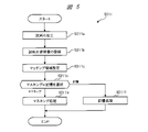
- FIG. 2 is a flow chart mainly showing an example of an initial setting process in a flowchart showing the operation of the charged particle beam device according to the first embodiment of the present invention.
- the initial setting step includes steps S010 to S150.
- the computer 21 selects a mode such as the presence / absence of an attitude control mode described later, observation conditions for template matching, and processing conditions (machining position, dimensions) according to the input of the operator. , Number, etc.) (step S010).
- a mode such as the presence / absence of an attitude control mode described later, observation conditions for template matching, and processing conditions (machining position, dimensions) according to the input of the operator. , Number, etc.) (step S010).
- FIG. 5 is a flow chart showing an example of a method of registering a sample piece reference image and setting an image matching region (S011a to S011f).
- the sample S is processed by the charged particle beam device 10a (step S011a).
- FIG. 6 is a plan view showing a sample piece Q formed on the sample S of the automatic sample piece preparation apparatus according to the first embodiment of the present invention.
- Reference numeral F in FIG. 6 indicates a processing frame by the focused ion beam, that is, a scanning range of the focused ion beam.
- the inside (white portion) of the scanning range F is a processing region H excavated by sputtering by focused ion beam irradiation.
- the shaded area is a region not sputtered by focused ion beam irradiation, that is, a region not excavated.
- the reference numeral Ref in FIG. 6 is a reference mark (reference point) indicating a position where the sample piece Q is formed.
- the reference mark Ref has a shape in which, for example, a deposition film (for example, a square having a side of 10 ⁇ m), which will be described later, is provided with fine holes having a diameter of, for example, 1 ⁇ m by a focused ion beam.
- the reference mark Ref can be recognized with good contrast in an image using a focused ion beam or an electron beam.
- a deposition film is used to recognize the approximate position of the sample piece Q, and fine holes are used to perform precise alignment.
- the reference mark Ref is not limited to the above-mentioned shape. It is also possible to use a processing mark processed into an arbitrary shape on the surface of the sample by the operator or a singular point originally possessed by the sample or the sample piece holder as the reference mark Ref.
- the sample piece Q is sputter-processed so that the peripheral portions on the side portion side and the bottom portion side are scraped off and removed, leaving the support portion Qa connected to the sample S, and the support portion Qa is used. It is cantilevered and supported by sample S (FIG. 6).
- the dimensions of the sample piece Q in the longitudinal direction are, for example, about 10 ⁇ m, 15 ⁇ m, and 20 ⁇ m, and the width (thickness) of the sample piece Q is, for example, about 500 nm, 1 ⁇ m, 2 ⁇ m, and 3 ⁇ m.
- the sample piece Q is a minute sample piece.
- step S011b the sample piece reference image is registered.
- the computer 21 takes an image of the sample from an arbitrary direction using the charged particle beam device 10a with respect to the sample S that has been processed as shown in FIG. 6 (hereinafter, also referred to as peripheral processing), and the photographed image. Is registered as a sample piece reference image.
- FIG. 7 is a diagram showing an example of a sample processing mark shape and a sample piece shape recognized from a reference image in the charged particle beam device according to the first embodiment of the present invention.
- the computer 21 recognizes the processing mark shape F and the sample piece shape Fa of the peripheral processing performed in advance around the sample piece Q automatically or based on the information input from the input device 22. Then, the computer 21 sets the region recognizing the machined mark shape F and the sample piece shape Fa as the matching region (FIG. 7). Alternatively, the computer 21 may set the matching area based on the information of an arbitrary position, size, and number input from the input device 22. If the matching area based on the information of an arbitrary position, size, and number is not specified, the computer 21 may set the entire area of the reference image as the matching area.
- the computer 21 When the computer 21 recognizes the processing mark shape F of the peripheral processing performed in advance around the sample piece Q, the computer 21 performs a masking process of masking the image of the region outside the frame line of the processing mark shape F shown in FIG. It is selected whether to perform a storage process for storing the area outside the frame line of the machined mark shape F (step S011d).
- the computer 21 stores and sets the selected process.
- the process selected and set here may be temporarily stored in the internal memory inside the computer 21, or may be stored, for example, in a storage device outside the computer 21.
- FIG. 8 is a diagram showing an example of an image in which a region outside the frame line of the machined mark shape is masked in the charged particle beam device according to the first embodiment of the present invention.
- the computer 21 masks the outer region of the machined mark shape F with respect to the reference image, for example, as shown in FIG.
- step S011d the computer 21 executes a process of storing the area outside the frame line of the machined mark shape F (step S011f).
- the computer 21 After registering the sample piece reference image and setting the image matching area (step S011), the computer 21 creates a template for the columnar portion 34 (steps S035 to S038).
- the computer 21 first performs a position registration process of the sample piece holder P installed on the holder fixing base 12a of the stage 12 by the operator (step S035).
- the computer 21 creates a template for the columnar portion 34 at the beginning of the sampling process.
- the computer 21 creates a template for each columnar portion 34.
- the computer 21 acquires the stage coordinates of each columnar portion 34 and creates a template, and stores the stage coordinate acquisition and the template as a set in association with each other.
- the computer 21 uses the stage coordinate acquisition and the template of the columnar portion 34 when determining the shape of the columnar portion 34 by template matching (superimposition of the template and the image) performed later.
- the computer 21 stores, for example, the image itself, edge information extracted from the image, and the like in advance as a template for the columnar portion 34 used for template matching. In a later process, the computer 21 can recognize the exact position of the columnar portion 34 by performing template matching after moving the stage 12 and determining the shape of the columnar portion 34 based on the template matching score. It is desirable to use the same observation conditions such as contrast and magnification as for template creation as the observation conditions for template matching because accurate template matching can be performed.
- the computer 21 performs the position registration process of the sample piece holder P prior to the movement of the sample piece Q, which will be described later, to confirm in advance that the sample table 33 having an appropriate shape actually exists. Can be done.
- the computer 21 moves the stage 12 by the stage drive mechanism 13 and aligns the irradiation area with the position where the sample table 33 is attached in the sample piece holder P.
- the computer 21 creates in advance from the design shape (CAD information) of the sample table 33 from each image data generated by irradiation of a charged particle beam (focused ion beam and electron beam) as a fine adjustment operation.
- the positions of the plurality of columnar portions 34 constituting the sample table 33 are extracted using the template.
- the computer 21 registers (stores) the position coordinates and the image of each of the extracted columnar portions 34 as the attachment position of the sample piece Q (step S036).
- each columnar portion 34 is compared with the prepared columnar portion design drawing, CAD diagram, or the image of the standard product of the columnar portion 34, and each columnar portion 34 is deformed, chipped, or missing. Check for the presence of such things, and if it is defective, remember that it is a defective product along with the coordinate position of the columnar part and the image.
- step S037 it is determined whether or not there is a columnar portion 34 to be registered in the sample piece holder P currently being executed in the registration process (step S037).
- this determination result is "NO" that is, when the remaining number m of the columnar portion 34 to be registered is 1 or more, the process is returned to step S036 described above, and step S036 until the remaining number m of the columnar portion 34 is exhausted. And S037 are repeated.
- the determination result is "YES" that is, if the remaining number m of the columnar portion 34 to be registered is zero, the process proceeds to step S038.
- the computer 21 When a plurality of sample piece holders P are installed on the holder fixing base 12a, the computer 21 displays the position coordinates of each sample piece holder P and the image data of the corresponding sample piece holder P together with the code number for each sample piece holder P. Record. Further, the computer 21 stores (registers) the code number and the image data corresponding to the position coordinates of each columnar portion 34 of each sample piece holder P. The computer 21 may sequentially perform this position registration process for the number of sample pieces Q for which automatic sample sampling is to be performed.
- the computer 21 determines whether or not there is a sample piece holder P to be registered (step S038).
- this determination result is "NO" that is, when the remaining number n of the sample piece holder P to be registered is 1 or more, the process is returned to the above-mentioned step S035 until the remaining number n of the sample piece holder P is exhausted. Steps S035 to S038 are repeated.
- the determination result is "YES" that is, if the remaining number n of the sample piece holder P to be registered is zero, the process proceeds to step S039.
- step S035 and S036 if the sample piece holder P itself or the columnar portion 34 is deformed or damaged and the sample piece Q is not in a state where it can be attached, the above Along with the position coordinates, image data, and code number, it is also registered as "unusable” (notation indicating that the sample piece Q cannot be attached). As a result, the computer 21 skips the "unusable" sample piece holder P or columnar portion 34 when the sample piece Q described later is transferred, and uses the next normal sample piece holder P or columnar portion 34. It can be moved within the observation field.
- the computer 21 recognizes the reference mark Ref formed in advance on the sample S by using the image data of the charged particle beam.
- the computer 21 recognizes the position of the sample piece Q from the relative positional relationship between the known reference mark Ref and the sample piece Q by using the recognized reference mark Ref, and puts the position of the sample piece Q into the observation field of view. Move to the stage (step S039).
- the computer 21 drives the stage 12 by the stage drive mechanism 13, and corresponds to the posture control mode so that the posture of the sample piece Q becomes a predetermined posture (for example, a posture suitable for taking out by the needle 18).
- the stage 12 is rotated about the Z axis by an angle (step S040).
- the computer 21 starts automatic processing of the sample.
- the computer 21 controls each component of the charged particle beam device 10a to process the sample S, for example, to prepare the sample piece shown in FIG.
- the computer 21 acquires, for example, an image of the sample S in which the sample piece Q is produced as a comparative image under the same conditions as the reference image shown in FIG. 7 (step S041).
- the computer 21 recognizes the reference mark Ref using the image data of the charged particle beam, the relative positional relationship between the known reference mark Ref and the sample piece Q, and various image matching using the reference image and the comparative image. (Image matching) is performed (steps S043 and S044 described later).
- step S042 the setting information of the process selected when the machining mark shape F of the peripheral machining performed in advance around the sample piece Q is recognized is confirmed.
- This setting information is set in step S011d described above.
- the computer 21 reads, for example, setting information regarding the processing selected when the processing mark shape F of the peripheral processing performed in advance around the sample piece Q is recognized from the internal memory or the external storage device, and confirms the setting information. I do.
- step S043 is executed.
- step S043 first, the comparative image acquired in step S041 is masked in the same area as the reference image. Then, the computer 21 performs image matching on the region where the masking is not performed for the reference image and the comparative image. Taking FIG. 8 as an example, image matching is performed on the area inside the machined mark shape F that is not painted in black.
- step S043 image matching is performed with respect to the matching area based on the matching area set in step S011c.
- step S044 is executed.
- FIG. 9 is a conceptual diagram of image matching when it is selected to store the area outside the frame line of the processing mark shape.
- the computer 21 uses a reference image and a comparative image for the region set in step S011c (here, for example, the region outside the frame line of the machined mark shape F). Perform matching.
- FIG. 10 is a conceptual diagram illustrating image matching in the case of storing a designated area.
- the computer 21 refers to the region Sa between the processing mark shape F surrounded by the thick black solid line shown in FIG. 10A and the outer periphery of the reference image also shown by the thick black solid line.
- Image matching is performed between the image and the comparative image shown in FIG. 10 (b). That is, also in step S044, image matching is performed with respect to the matching region (here, the region outside the frame line of the machined mark shape F) based on the matching region set in step S011c.
- FIG. 13 is a diagram illustrating another example of the image matching method.
- the computer 21 masks or stores the image of the area inside the frame line of the specified masking area MAS. Select.
- the computer 21 masks the masking region MAS in the reference image and the comparative image in step S043 (FIG. 13B), and performs image matching with respect to the masking region MAS.
- the computer 21 performs the designated area (in this case, as shown in FIG. 9) in step S044.
- the area inside the frame line of the sample piece shape Fa) is stored, and image matching of the reference image and the comparative image is performed.
- the computer 21 recognizes the position of the sample piece Q by image matching according to step S043 or S044, and aligns the sample piece Q (step S050).
- the computer 21 moves the needle (sample piece moving means) 18 to the initial setting position by the needle driving mechanism 19.
- the needle drive mechanism 19 and the needle 18 may be combined as a sample piece moving means.
- the initial setting position is, for example, a predetermined position in a preset visual field region, and is a predetermined position around the sample piece Q for which the alignment has been completed in the visual field region.
- the computer 21 approaches the nozzle 17a at the tip of the gas supply unit 17 to a predetermined position around the sample piece Q, for example, lowers it from the standby position vertically above the stage 12 (for example). Step S060).
- the computer 21 moves the needle 18, the reference mark Ref formed on the sample S at the time of performing the automatic processing for forming the sample piece Q is used, and the computer 21 uses the reference mark Ref formed on the sample S to form a three-dimensional positional relationship between the needle 18 and the sample piece Q. Can be grasped with high accuracy and can be moved properly.
- the computer 21 performs the following processing as a processing for bringing the needle 18 into contact with the sample piece Q.
- the computer 21 switches to the absorption current image mode and recognizes the position of the needle 18 (step S070).
- the computer 21 detects the absorption current flowing into the needle 18 by irradiating the needle 18 while scanning the charged particle beam, and generates absorption current image data by the charged particle beam irradiated from a plurality of different directions.
- the absorbed current image has the advantage that only the needle 18 can be reliably recognized without misidentifying the needle 18 and the background.
- the computer 21 acquires absorption current image data of the XY plane (plane perpendicular to the optical axis of the focused ion beam) by irradiating the focused ion beam, and XYZ plane (plane perpendicular to the optical axis of the electron beam) by irradiating the electron beam. ) Absorption current image data is acquired.
- the computer 21 can detect the tip position of the needle 18 in the three-dimensional space by using each absorption current image data acquired from two different directions.
- step S075 the shape of the needle 18 is determined. If it is determined that the needle 18 has a predetermined normal shape (OK), the process proceeds to the next step S080.
- step S075 if it is determined that the tip shape of the needle 18 is not in a state where the sample piece Q can be attached due to deformation or breakage (NG), a display such as "needle defect" is displayed and the device is operated. A warning is notified to the person (step S079), and the process proceeds to the subsequent step S150.
- the operation of automatic sample sampling is terminated without executing all the steps after step S080. That is, if the shape of the needle tip is defective, no further work can be performed, and the operator replaces the needle.
- the determination of the needle shape in step S075 is determined as a defective product if, for example, the needle tip position deviates from a predetermined position by 100 ⁇ m or more in an observation field of view of 200 ⁇ m on each side.
- the computer 21 drives the stage 12 by the stage drive mechanism 13 using the detected tip position of the needle 18, and sets the tip position of the needle 18 to the center position (field center) of the preset visual field region. It may be set.
- FIG. 11 is a diagram showing a template of the tip of the needle obtained by the focused ion beam.
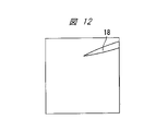
- FIG. 12 is a diagram showing a template of the tip of the needle obtained by the electron beam.
- the orientations of the needles 18 are different in FIGS. 11 and 12, due to the positional relationship between the focused ion beam irradiation optical system 14, the electron beam irradiation optical system 15, and the detector 16, and the orientation of the image to be displayed by secondary electrons. This is due to the difference, because the same needle 18 is viewed from different observation directions.
- the computer 21 drives the stage 12 by the stage drive mechanism 13 and irradiates the needle 18 while scanning the charged particle beam (focused ion beam and electron beam) with the sample piece Q retracted out of the field of view. do.
- the computer 21 acquires each image data showing the position distribution of the secondary charged particles (secondary electrons or secondary ions) R emitted from the needle 18 by the irradiation of the charged particle beam in a plurality of different planes.
- the computer 21 acquires image data of the XY plane by irradiating the focused ion beam, and acquires image data of the XYZ plane (plane perpendicular to the optical axis of the electron beam) by irradiating the electron beam.
- the computer 21 acquires the image data obtained by the focused ion beam and the electron beam and stores them as a template (reference image data).
- the computer 21 uses the image data actually acquired immediately before moving the needle 18 by the rough adjustment and the fine adjustment described later as the reference image data, the pattern has high accuracy regardless of the difference in the shape of each needle 18. Matching can be done. Further, since the computer 21 retracts the stage 12 and acquires each image data without a complicated structure in the background, the template (reference image) that can clearly grasp the shape of the needle 18 excluding the influence of the background. Data) can be obtained.
- the computer 21 uses image acquisition conditions such as suitable magnification, luminance, and contrast stored in advance in order to increase the recognition accuracy of the object. Further, the computer 21 may use the absorption current image data as a reference image instead of using the image data obtained by the secondary charged particles R as a reference image. In this case, the computer 21 may acquire each absorption current image data for two different planes without driving the stage 12 to retract the sample piece Q from the visual field region.
- step S080 When the process of step S080 is completed, the initial setting process is completed and the process of the sample piece pick-up process is executed. ⁇ Sample piece pick-up process>
- the sample piece pick-up process will be described.
- the process of picking up the sample piece Q from the sample S is performed in the automatic sample piece preparation operation by the charged particle beam device 10a.
- the pickup in the present embodiment means that the sample piece Q is separated and extracted from the sample S by processing with a focused ion beam or by a needle.
- FIG. 14 is a flow chart showing an example of the sample piece pick-up process according to the first embodiment of the present invention. As shown in FIG. 14, the sample piece pick-up step includes steps S090 to S140.
- step S090 the rough adjustment movement of the needle 18 is executed.
- the computer 21 outputs a control signal to the needle drive mechanism 19 and moves the needle 18 toward the sample piece Q. Further, the computer 21 recognizes the reference mark Ref (FIG. 6) from each image data obtained by the focused ion beam and the electron beam with respect to the sample S.
- the computer 21 sets the movement target position AP (FIG. 6) of the needle 18 by using the recognized reference mark Ref and each image data by the focused ion beam and the electron beam.
- the movement target position AP is a predetermined position on or near the sample piece Q required for processing to connect the needle 18 and the sample piece Q with the deposition film.
- the moving target position AP may be, for example, a position within the sample piece Q or a position slightly distant from the edge of the sample piece Q.
- the moving target position AP is a position based on a predetermined positional relationship with respect to the processing frame F at the time of forming the sample piece Q.
- the computer 21 stores information on the relative positional relationship between the processing frame F and the reference mark Ref when the sample piece Q is formed on the sample S by irradiation with the focused ion beam.
- Various information such as information on the relative positional relationship between the processing frame F and the reference mark Ref and setting information may be stored in the ROM in the computer 21 or stored in a storage device different from the computer 21. May be done.
- the computer 21 uses the recognized reference mark Ref and the reference mark Ref and the movement target position AP, or if necessary, information on the relative positional relationship between the processing frame F and the reference mark Ref, and the needle 18 is used.
- the tip is moved toward the movement target position AP in the three-dimensional space.
- the computer 21 may be moved in the X direction and the Y direction, and then in the Z direction, for example.
- FIG. 15 is a diagram showing the vicinity of the tip of the needle in the image obtained by the focused ion beam of the charged particle beam device according to the first embodiment of the present invention.
- FIG. 16 is a diagram showing the vicinity of the tip of the needle in the image obtained by the electron beam of the charged particle beam device according to the first embodiment of the present invention. 15 and 16 show how the needle 18 moves. The reason why the orientation of the needle 18 is different between FIGS. 15 and 16 is as described with reference to FIGS. 11 and 12.
- FIG. 16 superimposes image data near the tip of the needle 18 before and after the movement in the same field of view in order to show the movement state of the needle 18. It is displayed as. Therefore, the needles 18a and 18b are the same needle 18.
- step S100 the fine adjustment movement of the needle 18 is executed.
- the computer 21 repeatedly executes pattern matching using reference image data to grasp the position of the tip of the needle 18, outputs a control signal to the needle drive mechanism 19, and moves the needle 18.
- the computer 21 irradiates the needle 18 with a charged particle beam (each of a focused ion beam and an electron beam), and repeatedly acquires each image data by the charged particle beam.
- the computer 21 acquires the tip position of the needle 18 by performing pattern matching using the reference image data with respect to the acquired image data.
- the computer 21 moves the needle 18 in the three-dimensional space according to the acquired tip position and movement target position AP of the needle 18.
- FIG. 17 is a diagram showing the tip of a needle and a sample piece in the image data obtained by the focused ion beam of the charged particle beam device according to the first embodiment of the present invention.
- FIG. 18 is a diagram showing a tip of a needle and a sample piece in image data obtained by an electron beam of the charged particle beam device according to the first embodiment of the present invention. 17 and 18 show a state when the needle 18 is stopped.
- the focused ion beam and the electron beam have different observation directions and different observation magnifications, but the observation target and the needle 18 are the same. be.
- step S110 the computer 21 moves the needle 18 in a state where the charged particle beam is irradiated to the irradiation region including the movement target position AP.
- the computer 21 determines that the absorbed current flowing through the needle 18 exceeds a predetermined current, or when the computer 21 determines that the coordinates of the tip of the needle have reached the predetermined moving target position AP, the needle driven mechanism 19 determines that the needle has reached a predetermined moving target position AP.
- the drive of 18 is stopped.
- the computer 21 arranges the tip position of the needle 18 at the movement target position AP.
- FIG. 19 is a diagram showing a processing frame including a connection processing position of a needle and a sample piece in image data obtained by a focused ion beam of the charged particle beam device according to the first embodiment of the present invention.
- FIG. 19 shows how the needle 18 is connected to the sample piece Q, and shows the deposition film forming region DM2 (FIG. 20 described later) including the connection processing position between the needle 18 and the sample piece Q.
- the computer 21 uses the reference mark Ref of the sample S to specify a preset connection processing position.
- the computer 21 sets the connection processing position to a position separated from the sample piece Q by a predetermined interval.
- the computer 21 sets the upper limit of the predetermined interval to, for example, 1 ⁇ m, and preferably sets the predetermined interval to 100 nm or more and 200 nm or less.
- the computer 21 supplies gas to the sample piece Q and the tip surface of the needle 18 by the gas supply unit 17 while irradiating the irradiation region including the processing frame R1 set at the connection processing position with the focused ion beam for a predetermined time. do.
- the computer 21 connects the sample piece Q and the needle 18 with the deposition film DM2 (FIG. 20 described later).
- step S120 the computer 21 does not bring the needle 18 into direct contact with the sample piece Q, arranges the needle 18 at a position slightly spaced apart, and connects the needle 18 and the sample piece Q with a deposition film. According to this method, there is an advantage that defects such as damage to the sample piece Q and the sample S due to the needle 18 coming into direct contact with the sample piece Q can be prevented.
- the computer 21 is suitable for each approach mode (details will be described later) selected when the needle 18 is connected to the sample piece Q and later the sample piece Q connected to the needle 18 is transferred to the sample piece holder P.
- Set the connection posture The computer 21 sets the relative connection posture between the needle 18 and the sample piece Q corresponding to each of a plurality of different approach modes described later.
- the computer 21 may determine the connection state by the deposition film by detecting the change in the absorption current of the needle 18. When the absorption current of the needle 18 reaches a predetermined current value, the computer 21 determines that the sample piece Q and the needle 18 are connected by the deposition film, and determines that the deposition film is connected regardless of the passage of a predetermined time. The formation of the current may be stopped.
- FIG. 20 is a diagram showing the cutting processing position of the support portion of the sample and the sample piece in the image data obtained by the focused ion beam of the charged particle beam device according to the first embodiment of the present invention.
- FIG. 20 shows how the support portion Qa between the sample piece Q and the sample S is cut.
- step S130 the computer 21 uses the reference mark Ref formed on the sample S to specify the preset cutting processing position T1 of the support portion Qa.
- the computer 21 separates the sample piece Q from the sample S by irradiating the cutting processing position T1 with a focused ion beam for a predetermined time.
- step S133 the computer 21 determines whether or not the sample piece Q is separated from the sample S by detecting the continuity between the sample S and the needle 18 (step S133).
- step S133 the computer 21 conducts conduction between the sample S and the needle 18 after the cutting process is completed, that is, after the cutting of the support portion Qa between the sample piece Q and the sample S at the cutting process position T1 is completed.
- NG the sample piece Q is not separated from the sample S
- the computer 21 indicates on the display device 20 that the separation between the sample piece Q and the sample S has not been completed. Notify by a warning sound (step S136). Then, the execution of the subsequent processing is stopped, or needle cleaning is performed, and the next sampling is performed.
- step S133 if the computer 21 does not detect the continuity between the sample S and the needle 18, it is determined that the sample piece Q is separated from the sample S (OK), and the process proceeds to step S140.
- step S140 the computer 21 removes the needle 18 to which the sample piece Q is connected and retracts the needle 18.
- FIG. 21 is a diagram showing a state in which a sample piece is extracted in the image data obtained by the electron beam of the charged particle beam device according to the first embodiment of the present invention.
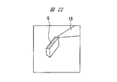
- FIG. 22 is a diagram showing a state in which the needle to which the sample piece is connected in the image data obtained by the electron beam of the charged particle beam device according to the first embodiment of the present invention is retracted.
- the computer 21 raises the needle 18 vertically upward (positive direction in the Z direction) by a predetermined distance by the needle driving mechanism 19.
- the degree (height) of raising the needle 18 differs between the removal of the needle 18 and the retracting of the needle 18. Specifically, when the needle 18 is removed, the needle 18 rises to a position where the sample piece Q connected to the needle 18 is higher in the Z direction than the sample S. On the other hand, when the needle 18 is retracted, the needle 18 to which the sample piece Q is connected rises to about step S060.
- the computer 21 operates the needle drive mechanism 19, and the sample connected to the needle 18 and the needle 18 so that the sample piece Q taken out from the sample S is perpendicular or parallel to the end face of the columnar portion 34 on the surface of the sample S. Rotate one piece Q. At that time, the computer 21 corrects the rotation so that the sample piece Q does not deviate from the actual field of view by performing the eccentricity correction.
- the computer 21 can secure the posture of the sample piece Q suitable for the finishing process to be executed later, and can reduce the influence of the curtain effect generated at the time of the thinning finishing process of the sample piece Q.
- the curtain effect means that a processed fringe pattern is formed by focused ion beam irradiation from a single direction due to the difference in density in the sample, and when the completed sample piece is observed with an electron microscope, it gives an incorrect interpretation. A phenomenon that can occur.
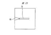
- FIGS. 23 to 24 are diagrams illustrating a state near the tip of the needle when the needle is not rotated.
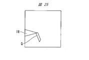
- 25 to 28 are views illustrating a state near the tip of the needle when the needle is rotated.
- FIG. 23 shows the state of the needle 18 to which the sample piece Q in the image data obtained by the focused ion beam is connected in the approach mode at the rotation angle of the needle of 0 °.
- FIG. 24 shows the state of the needle 18 to which the sample piece Q in the image data obtained by the electron beam is connected in the approach mode at the rotation angle of the needle of 0 °.
- the computer 21 can set a posture state suitable for transferring the sample piece Q to the sample piece holder P without rotating the needle 18.
- FIG. 25 shows a state in which the needle 18 to which the sample piece Q in the image data obtained by the focused ion beam is connected is rotated by 90 ° in the approach mode at the rotation angle of the needle 18 at 90 °.
- FIG. 26 shows a state in which the needle 18 to which the sample piece Q in the image data obtained by the electron beam is connected is rotated by 90 ° in the approach mode at the rotation angle of the needle 18 at 90 °.
- the computer 21 may set a posture state suitable for transferring the sample piece Q to the sample piece holder P with the needle 18 rotated by 90 °. can.
- FIG. 27 shows a state in which the needle 18 to which the sample piece Q in the image data obtained by the focused ion beam is connected is rotated by about 90 ° in the approach mode at the rotation angle of the needle 18 at 180 °.
- FIG. 28 shows a state in which the needle 18 to which the sample piece Q in the image data obtained by the electron beam is connected is rotated by about 90 ° in the approach mode at the rotation angle of the needle 18 of 180 °.
- the needle rotates 90 ° and the mesh (not shown) tilts 90 °, so that the sample rotates 180 °.
- the computer 21 sets a posture state suitable for transferring the sample piece Q to the sample piece holder P with the needle 18 rotated by about 90 °. Can be done.
- the relative connection posture between the needle 18 and the sample piece Q is set to a connection posture suitable for each approach mode when the needle 18 is connected to the sample piece Q in the sample piece pick-up process described above.
- the approach of the needle 18 to the sample piece Q by the rotation angles of 0 °, 90 °, and 180 ° is to move and rotate the stage 12 by the stage drive mechanism 13 to move the needle 18 to the movement target position AP from an appropriate direction. Bring them closer. At that time, the positional relationship between the needle 18 and the sample piece Q when the needle 18 reapproaches the movement target position AP can be changed by the rotation angle of the stage 12.
- the computer 21 irradiates the sample with a charged particle beam in advance to obtain a reference image and the sample S to be extracted from the sample piece Q. Select a matching region for image matching with the comparative image obtained by irradiating the charged particle beam. According to this configuration, the needle 18 can be reliably arranged in the vicinity of the sample piece Q, so that the automatic extraction of the sample piece Q can be performed accurately and stably.
- the computer 12 when the computer 12 recognizes the processing mark shape F of the peripheral processing performed in advance around the sample piece Q, the computer 12 displays an image of a region outside the frame line of the processing mark shape F.
- Masking Select whether to perform masking processing or to store the area outside the frame line of the machined mark shape.
- the computer 21 performs image matching of the reference image and the comparative image in a region other than the region outside the frame line of the machined mark shape F to which the masking process has been performed. According to this configuration, the alignment between the needle 18 and the sample piece Q can be performed more accurately, so that the automatic extraction of the sample piece Q can be performed accurately and stably.
- the computer 21 when the computer 21 recognizes the processing mark shape F of the peripheral processing performed in advance around the sample piece Q, the computer 21 displays an image of a region outside the frame line of the processing mark shape F.
- Masking Select whether to perform masking processing or to store the area outside the frame line of the machined mark shape. Then, when storage is selected, the computer 21 stores the image in the region outside the frame line of the stored processing mark shape F, and in the region outside the frame line of the stored processing mark shape F. Image matching of the reference image and the comparative image is performed. According to this configuration, the alignment between the needle 18 and the sample piece Q can be performed more accurately, so that the automatic extraction of the sample piece Q can be performed accurately and stably. Further, the masking process can be omitted, and the load on the computer 21 is reduced.
- the computer 21 creates a template of the needle 18 based on an image acquired by irradiating the needle 18 before connecting with the sample piece Q with a charged particle beam. Then, the computer 21 uses the charged particle beam irradiation optical system and the charged particle beam irradiation optical system so as to irradiate the deposition film attached to the needle 18 with the charged particle beam based on the peripheral processing obtained by the template matching using the template or the sample piece shape F. Control the needle. According to this configuration, since the posture of the sample piece Q connected to the needle 18 can be recognized, the sample piece Q can be reliably conveyed to the sample piece holder P.
- the display device 20 for displaying the peripheral processing or the sample piece shape F is provided. According to this configuration, it is possible to notify the operator of the operating state, warning, etc. of the charged particle beam device 10a.
- the sample piece moving means includes a needle 18 or tweezers connected to the sample piece Q. According to this configuration, the configuration of the sample piece moving means can be freely changed according to the shape of the sample S and the sample piece Q, and the versatility can be improved.
- the computer 21 identifies the position or the processed portion of the needle 18 by image matching. According to this configuration, the alignment between the needle 18 and the sample piece Q can be performed more accurately, so that the automatic extraction of the sample piece Q can be performed accurately and stably. (Embodiment 2)
- FIG. 29 is a diagram showing a reference image according to the second embodiment of the present invention.
- the computer 21 masks the reference image and the comparative image in the region inside the frame line of the sample piece shape Fa (FIG. 5). Step S011e).
- the computer 21 performs image matching on the reference image and the comparative image with respect to the area other than the masked area (step S043 in FIG. 2). That is, in this modification, image matching is performed on the region outside the frame line of the sample piece shape Fa based on the matching region set in step S011c of FIG.
- step S011d when the storage process for storing the area inside the frame line of the sample piece shape Fa is selected in step S011d, the process for storing the area inside the frame line of the sample piece shape Fa in step S011f of FIG. Is executed. Then, the computer 21 performs image matching using the reference image and the comparison image for the designated region (here, the region inside the frame line of the sample piece shape Fa) as shown in FIG. (Step S0044 in FIG. 2). ⁇ Main effects of this embodiment>
- the computer 12 when the computer 12 recognizes the sample piece shape Fa around the sample piece Q, the computer 12 performs a masking process for masking the image of the region inside the frame line of the sample piece shape Fa, or the sample. Select whether to store the area inside the border of the one-sided shape.
- the computer 12 performs the masking process on the reference image and the comparative image in the region inside the frame line of the sample piece shape Fa on which the masking process is performed.
- the computer 21 when storage is selected, the computer 21 performs masking processing on the reference image and the comparative image in the region inside the frame line of the stored sample piece shape Fa. According to this configuration, the needle 18 and the sample piece Q Since the alignment between the sample piece Q and the sample piece Q can be performed more accurately, the automatic extraction of the sample piece Q can be performed accurately and stably. Further, the masking process can be omitted, and the load on the computer 21 is reduced. (Embodiment 3)
- FIG. 30 is a conceptual diagram showing an example of image matching using a trained model.
- the computer 21 generates a trained model MODEL in which information on a plurality of sample structures of a sample is trained as a reference image from a plurality of images.
- the computer 21 performs image recognition using the trained model MODEL on the input comparative image.
- the computer 21 masks the comparative image in a region that cannot be discriminated by image recognition.
- the computer 21 performs image matching using the reference image and the masked comparative image.
- FIG. 31 is a diagram illustrating another example of image matching using the trained model.
- the computer 21 designates the entire area of the reference image or a plurality of regions of arbitrary positions and sizes of the reference image for the plurality of images acquired by the secondary electron images shown in FIG. 31 (a), and the designated regions are designated. Memorize and learn images as reference images.
- the computer 21 acquires the comparative image shown in FIG. 31 (b) from the secondary electron image obtained by irradiating the sample with the charged particle beam.
- the computer 21 compares the acquired comparative image with the stored reference image.
- the computer 21 masks the reference image in a region where the pattern is different from that of the comparative image (FIG. 31 (c)).
- the computer 21 performs a matching process using the masked reference image and the comparison image.
- the computer 21 controls the needle driving mechanism 19 by using the matching result and the tip coordinates of the needle 18, and brings the needle 18 closer to the sample S.
- FIG. 32 is a conceptual diagram illustrating another example of image matching using a trained model.
- the computer 21 generates a trained model MODEL in which information on a plurality of sample structures of a sample is trained in advance as a reference image using a plurality of images.
- the computer 21 uses the trained model MODEL to perform image recognition processing on the input comparative image. Then, the computer 21 performs image matching only on the region of the comparative image that can be determined by the image recognition process.
- the image recognition process is also executed when the trained model MODEL is created.
- the image recognition process is executed using, for example, a well-known algorithm that performs image segmentation, image detection, and the like.
- the computer 21 extracts information on the sample structure from the image recognition result for the input image, machine-learns the composition of the sample, and generates a trained model MODEL (reference image). Further, the computer 21 also performs image recognition processing on the comparative image in the same manner as when the trained model MODEL is created. It should be noted that different algorithms may be used when the trained model MODEL is generated and when the comparative image is generated.
- FIG. 33 is a diagram illustrating a specific example of FIG. 32.
- the computer 21 designates a plurality of regions of the entire reference image or an arbitrary position and size of the reference image in the plurality of reference images acquired by the secondary electron image, and stores and learns the image of the designated region ().
- the computer 21 acquires a comparative image from the secondary electron image obtained by irradiating the sample with the charged particle beam.
- the computer 21 compares the acquired comparative image with the stored image (image in a designated area).
- the computer 21 performs the image matching process only in the region AREA of the similar pattern in the reference image and the comparative image (FIG. 33 (FIG. 33). b)).
- the computer 21 controls the needle driving mechanism by using the matching result and the tip coordinates of the needle to bring the needle closer to the sample.
- the trained model may be created by the computer 21 or may be created by an external device. ⁇ Main effects of this embodiment>
- the computer 21 generates a trained model MODEL in which information on a plurality of sample structures of a sample is trained as a reference image from a plurality of images. Then, the computer 21 performs an image recognition process on the comparative image using the trained model MODEL, and performs a masking process on the comparative image in a region that cannot be discriminated by the image recognition process. Then, the computer 21 performs image matching using the reference image and the comparative image subjected to the masking process. According to this configuration, even if the reference image and the comparative image do not completely match, the processing mark shape F and the sample piece shape Fa can be recognized by image recognition, so that the sample can be improved in versatility. It is possible to accurately and stably perform automatic extraction of the piece Q.
- the computer 21 performs image recognition processing on the comparative image by image segmentation. According to this configuration, an algorithm for performing image segmentation is easily available, and it is easy to implement image segmentation.
- the computer determines that the comparative image has a pattern similar to any region of the reference image in the image recognition process for the comparative image using the trained model
- the reference image is used.
- masking is performed on the area where the pattern is different from the comparative image.
- the computer 21 may execute software to realize each functional block, or some functional blocks may be configured by hardware such as LSI.
- the needle 18 has been described as an example of a sharpened needle-shaped member, but the needle 18 may have a shape such as a flat ridge with a flat tip, or like tweezers.
- the mechanism may be provided.
- the computer 21 files the set values such as acceleration (voltage, etc.), current value, ion beam scan range, ion beam scan speed, ion beam scan time, and dose amount of the ion beam used for peripheral processing.
- Data can be saved in a batch by associating with the name. In addition, it is possible to process under the set conditions by recalling the saved data.
- the matching region by setting the matching region in advance, it is possible to automatically extract the sample including the acquisition of the reference image.
- the machining depth is calculated at the same time as recognizing the machining position, and after peripheral machining, an SEM image is acquired by FOV that is judged to be appropriate, and the same image is used as a reference image for sample template matching. do.
- the computer 21 automatically recognizes the peripheral processing marks and the sample piece shape in the reference image, masks the images outside the frame line of the peripheral processing marks and inside the frame line of the sample piece shape, and then refers to them. Matching with the comparative image is performed using the entire area of the image.
- a charged particle beam device that automatically extracts sample pieces from a sample.
- a sample piece moving means for holding and transporting the sample piece extracted from the sample
- a holder fixing base for holding the sample piece holder to which the sample piece is transferred
- the computer With a computer Equipped with The computer generates a trained model in which information on a plurality of sample structures of the sample is trained as the reference image from a plurality of images, performs image recognition processing on the comparative image using the trained model, and performs the image recognition process. Image matching is performed only on the area of the comparative image that can be determined by the image recognition process.
- Charged particle beam device is provided.
- the automatic sample piece preparation device 10 is an automatic sample piece preparation device that automatically prepares a sample piece from a sample, and is at least a plurality of charged particles irradiated with a charged particle beam. It has a beam irradiation optical system (beam irradiation optical system), a sample stage on which the sample is placed and moved, and a needle connected to the sample piece separated and extracted from the sample, and conveys the sample piece.
- the sample piece transfer means, the holder fixing base for holding the sample piece holder to which the sample piece is transferred, and the gas supply unit for supplying the gas forming the deposition film by the charged particle beam are connected to the sample piece.
- the needle By irradiating the needle separated from the sample piece with the charged particle beam based on the image of the needle obtained earlier by the charged particle beam, the needle is substantially the same as the needle before being connected to the sample piece. It includes at least the charged particle beam irradiation optical system and a computer for controlling the sample piece transfer means so as to shape the sample into a shape.
- the automatic sample piece preparation device 10 is an automatic sample piece preparation device that automatically prepares a sample piece from a sample, and at least irradiates a focused ion beam to irradiate the focused ion beam.
- a sample piece that has an optical system (beam irradiation optical system), a sample stage on which the sample is placed and moved, and a needle that connects to the sample piece that is separated and extracted from the sample, and conveys the sample piece.
- the shape is substantially the same as the needle before being connected to the sample piece. It comprises at least the focused ion beam irradiation optical system and a computer for controlling the sample piece transfer means so as to shape the sample.
- the charged particle beam includes at least a focused ion beam and an electron beam.
- 10 Automatic sample piece preparation device, 10a ... Charged particle beam device, 11 ... Sample chamber, 12 ... Stage (sample stage), 13 ... Stage drive mechanism, 14 ... Focused ion beam irradiation optical system (charged particle beam irradiation optical system) , 15 ... electron beam irradiation optical system (charged particle beam irradiation optical system), 16 ... detector, 17 ... gas supply unit, 18 ... needle, 19 ... needle drive mechanism, 20 ... display device, 21 ... computer, 22 ... input Device, 33 ... sample table, 34 ... columnar part, P ... sample piece holder, Q ... sample piece, R ... secondary charged particle, S ... sample.
Abstract
Description
(実施の形態1)
<荷電粒子ビーム装置の構成>
<初期設定工程>
<<試料片参照像の登録および画像マッチング領域の設定>>
<試料片ピックアップ工程>
<その他の構成>
<本実施の形態による主な効果>
(実施の形態2)
<本実施の形態による主な効果>
(実施の形態3)
<本実施の形態による主な効果>
前記試料を載置して移動する試料ステージと、
荷電粒子ビームを照射する荷電粒子ビーム照射光学系と、
前記試料から摘出する前記試料片を保持して搬送する試料片移動手段と、
前記試料片が移設される試料片ホルダを保持するホルダ固定台と、
コンピュータと、
を備え、
前記コンピュータは、複数の画像から前記試料の複数の試料構造の情報を前記参照像として学習させた学習済みモデルを生成し、前記学習済みモデルを用いた前記比較像に対する画像認識処理を行い、前記比較像のうち前記画像認識処理により判別できた領域に対してのみ画像マッチングを行う、
荷電粒子ビーム装置。
Claims (12)
- 試料から試料片を自動的に摘出する荷電粒子ビーム装置であって、
前記試料を載置して移動する試料ステージと、
荷電粒子ビームを照射する荷電粒子ビーム照射光学系と、
前記試料から摘出する前記試料片を保持して搬送する試料片移動手段と、
前記試料片が移設される試料片ホルダを保持するホルダ固定台と、
コンピュータと、
を備え、
前記コンピュータは、前記試料片移動手段を前記試料片に接近させる際、予め前記荷電粒子ビームを前記試料に照射して得られた参照像と、前記試料片の摘出対象である前記試料に前記荷電粒子ビームを照射して得られた比較像との画像マッチングを行うマッチング領域を選択する、
荷電粒子ビーム装置。 - 請求項1に記載の荷電粒子ビーム装置において、
前記コンピュータは、前記試料片の周辺に予め実施された周辺加工の加工痕形状を認識した場合、前記加工痕形状の枠線より外側の領域の画像をマスキングするマスキング処理を行うか、前記加工痕形状の枠線の外側の領域を記憶するかを選択し、前記マスキング処理を選択した場合、前記マスキング処理を行った前記加工痕形状の枠線より外側の領域において、前記参照像および前記比較像に対する前記マスキング処理を行う、
荷電粒子ビーム装置。 - 請求項1に記載の荷電粒子ビーム装置において、
前記コンピュータは、前記試料片の周辺に予め実施された周辺加工の加工痕形状を認識した場合、前記加工痕形状の枠線より外側の領域の画像をマスキングするマスキング処理を行うか、前記加工痕形状の枠線の外側の領域を記憶するかを選択し、前記記憶を選択した場合、記憶した前記加工痕形状の枠線より外側の領域において、前記参照像および前記比較像に対する前記マスキング処理を行う、
荷電粒子ビーム装置。 - 請求項1に記載の荷電粒子ビーム装置において、
前記コンピュータは、前記試料片の周辺に試料片形状を認識した場合、前記試料片形状の枠線より内側の領域の画像をマスキングするマスキング処理を行うか、前記試料片形状の枠線の内側の領域を記憶するかを選択し、前記マスキング処理を選択した場合、前記マスキング処理を行った前記試料片形状の枠線より内側の領域において、前記参照像および前記比較像に対する前記マスキング処理を行う、
荷電粒子ビーム装置。 - 請求項1に記載の荷電粒子ビーム装置において、
前記コンピュータは、前記試料片の周辺に試料片形状を認識した場合、前記試料片形状の枠線より内側の領域の画像をマスキングするマスキング処理を行うか、前記試料片形状の枠線の内側の領域を記憶するかを選択し、前記記憶を選択した場合、記憶した前記試料片形状の枠線より内側の領域において、前記参照像および前記比較像に対する前記マスキング処理を行う、
荷電粒子ビーム装置。 - 試料から試料片を自動的に摘出する荷電粒子ビーム装置であって、
前記試料を載置して移動する試料ステージと、
荷電粒子ビームを照射する荷電粒子ビーム照射光学系と、
前記試料から摘出する前記試料片を保持して搬送する試料片移動手段と、
前記試料片が移設される試料片ホルダを保持するホルダ固定台と、
コンピュータと、
を備え、
前記コンピュータは、複数の画像から前記試料の複数の試料構造の情報を前記参照像として学習させた学習済みモデルを生成し、前記学習済みモデルを用いた前記比較像に対する画像認識処理を行い、前記比較像に対し、前記画像認識処理で判別できない領域にマスキング処理を行い、前記参照像と前記マスキング処理が行われた前記比較像とを用いて画像マッチングを行う、
荷電粒子ビーム装置。 - 請求項6に記載の荷電粒子ビーム装置において、
前記コンピュータは、画像セグメンテーションにより前記比較像に対する前記画像認識処理を行う、
荷電粒子ビーム装置。 - 試料から試料片を自動的に摘出する荷電粒子ビーム装置であって、
前記試料を載置して移動する試料ステージと、
荷電粒子ビームを照射する荷電粒子ビーム照射光学系と、
前記試料から摘出する前記試料片を保持して搬送する試料片移動手段と、
前記試料片が移設される試料片ホルダを保持するホルダ固定台と、
コンピュータと、
を備え、
前記コンピュータは、複数の画像から前記試料の複数の試料構造の情報を前記参照像として学習させた学習済みモデルを生成し、前記学習済みモデルを用いた前記比較像に対する画像認識処理を行い、前記比較像に前記参照像のいずれかの領域と同様のパターンが存在すると判断した場合、前記参照像に対し、前記比較像とパターンが異なる領域にマスキングを行う、
荷電粒子ビーム装置。 - 請求項1に記載の荷電粒子ビーム装置において、
前記コンピュータは、前記試料片と接続する前の前記試料片移動手段に対する前記荷電粒子ビームの照射により取得した画像に基づき前記試料片移設手段のテンプレートを作成し、前記テンプレートを用いたテンプレートマッチングによって得られる周辺加工または前記試料片形状に基づき、前記試料片移動手段に付着しているデポジション膜に前記荷電粒子ビームを照射するよう前記荷電粒子ビーム照射光学系および前記試料片移動手段を制御する、
荷電粒子ビーム装置。 - 請求項9に記載の荷電粒子ビーム装置において、
前記周辺加工または前記試料片形状を表示する表示装置を備える、
荷電粒子ビーム装置。 - 請求項1に記載の荷電粒子ビーム装置において、
前記試料片移動手段は、前記試料片に接続するニードルまたはピンセットを備える、
荷電粒子ビーム装置。 - 請求項1に記載の荷電粒子ビーム装置において、
前記コンピュータは、前記画像マッチングにより、前記試料片移動手段の位置または加工箇所の特定を行う、
荷電粒子ビーム装置。
Priority Applications (3)
| Application Number | Priority Date | Filing Date | Title |
|---|---|---|---|
| JP2022570862A JPWO2022137401A1 (ja) | 2020-12-23 | 2020-12-23 | |
| PCT/JP2020/048255 WO2022137401A1 (ja) | 2020-12-23 | 2020-12-23 | 荷電粒子ビーム装置 |
| US18/267,502 US20240055220A1 (en) | 2020-12-23 | 2020-12-23 | Charged Particle Beam Device |
Applications Claiming Priority (1)
| Application Number | Priority Date | Filing Date | Title |
|---|---|---|---|
| PCT/JP2020/048255 WO2022137401A1 (ja) | 2020-12-23 | 2020-12-23 | 荷電粒子ビーム装置 |
Publications (1)
| Publication Number | Publication Date |
|---|---|
| WO2022137401A1 true WO2022137401A1 (ja) | 2022-06-30 |
Family
ID=82159258
Family Applications (1)
| Application Number | Title | Priority Date | Filing Date |
|---|---|---|---|
| PCT/JP2020/048255 WO2022137401A1 (ja) | 2020-12-23 | 2020-12-23 | 荷電粒子ビーム装置 |
Country Status (3)
| Country | Link |
|---|---|
| US (1) | US20240055220A1 (ja) |
| JP (1) | JPWO2022137401A1 (ja) |
| WO (1) | WO2022137401A1 (ja) |
Citations (4)
| Publication number | Priority date | Publication date | Assignee | Title |
|---|---|---|---|---|
| JPH103544A (ja) * | 1996-06-14 | 1998-01-06 | Imeeji Joho Kagaku Kenkyusho | ジェスチャ認識装置 |
| JP2012155637A (ja) * | 2011-01-28 | 2012-08-16 | Hitachi High-Technologies Corp | パターンマッチング装置、及びコンピュータープログラム |
| JP2013242757A (ja) * | 2012-05-22 | 2013-12-05 | Sony Corp | 画像処理装置及び画像処理方法、並びにコンピューター・プログラム |
| JP2019179700A (ja) * | 2018-03-30 | 2019-10-17 | 株式会社日立ハイテクサイエンス | 荷電粒子ビーム装置 |
-
2020
- 2020-12-23 WO PCT/JP2020/048255 patent/WO2022137401A1/ja active Application Filing
- 2020-12-23 US US18/267,502 patent/US20240055220A1/en active Pending
- 2020-12-23 JP JP2022570862A patent/JPWO2022137401A1/ja active Pending
Patent Citations (4)
| Publication number | Priority date | Publication date | Assignee | Title |
|---|---|---|---|---|
| JPH103544A (ja) * | 1996-06-14 | 1998-01-06 | Imeeji Joho Kagaku Kenkyusho | ジェスチャ認識装置 |
| JP2012155637A (ja) * | 2011-01-28 | 2012-08-16 | Hitachi High-Technologies Corp | パターンマッチング装置、及びコンピュータープログラム |
| JP2013242757A (ja) * | 2012-05-22 | 2013-12-05 | Sony Corp | 画像処理装置及び画像処理方法、並びにコンピューター・プログラム |
| JP2019179700A (ja) * | 2018-03-30 | 2019-10-17 | 株式会社日立ハイテクサイエンス | 荷電粒子ビーム装置 |
Also Published As
| Publication number | Publication date |
|---|---|
| JPWO2022137401A1 (ja) | 2022-06-30 |
| US20240055220A1 (en) | 2024-02-15 |
Similar Documents
| Publication | Publication Date | Title |
|---|---|---|
| JP7008355B2 (ja) | 自動試料作製装置および自動試料作製方法 | |
| KR102646112B1 (ko) | 하전 입자 빔 장치 | |
| TWI751225B (zh) | 帶電粒子束裝置 | |
| CN108335961B (zh) | 带电粒子束装置 | |
| JP7109051B2 (ja) | 荷電粒子ビーム装置 | |
| JP6700897B2 (ja) | 荷電粒子ビーム装置 | |
| JP6542608B2 (ja) | 荷電粒子ビーム装置 | |
| CN109841534B (zh) | 截面加工观察方法、带电粒子束装置 | |
| KR102358551B1 (ko) | 자동 시료편 제작 장치 | |
| JP6105530B2 (ja) | 自動試料片作製装置 | |
| CN105910855B (zh) | 带电粒子束装置 | |
| WO2022137401A1 (ja) | 荷電粒子ビーム装置 | |
| JP6885637B2 (ja) | 荷電粒子ビーム装置 | |
| KR102657389B1 (ko) | 하전 입자 빔 장치 | |
| JP6629502B2 (ja) | 自動試料片作製装置 | |
| TW202311719A (zh) | 帶電粒子束裝置 | |
| KR102489385B1 (ko) | 하전 입자 빔 장치 |
Legal Events
| Date | Code | Title | Description |
|---|---|---|---|
| 121 | Ep: the epo has been informed by wipo that ep was designated in this application |
Ref document number: 20966183 Country of ref document: EP Kind code of ref document: A1 |
|
| ENP | Entry into the national phase |
Ref document number: 2022570862 Country of ref document: JP Kind code of ref document: A |
|
| WWE | Wipo information: entry into national phase |
Ref document number: 18267502 Country of ref document: US |
|
| NENP | Non-entry into the national phase |
Ref country code: DE |
|
| 122 | Ep: pct application non-entry in european phase |
Ref document number: 20966183 Country of ref document: EP Kind code of ref document: A1 |