WO2022137272A1 - Measurement device and measurement method - Google Patents
Measurement device and measurement method Download PDFInfo
- Publication number
- WO2022137272A1 WO2022137272A1 PCT/JP2020/047591 JP2020047591W WO2022137272A1 WO 2022137272 A1 WO2022137272 A1 WO 2022137272A1 JP 2020047591 W JP2020047591 W JP 2020047591W WO 2022137272 A1 WO2022137272 A1 WO 2022137272A1
- Authority
- WO
- WIPO (PCT)
- Prior art keywords
- voltage
- electrode
- concentration
- time
- measurement
- Prior art date
Links
Images


Classifications
-
- G—PHYSICS
- G01—MEASURING; TESTING
- G01N—INVESTIGATING OR ANALYSING MATERIALS BY DETERMINING THEIR CHEMICAL OR PHYSICAL PROPERTIES
- G01N27/00—Investigating or analysing materials by the use of electric, electrochemical, or magnetic means
- G01N27/26—Investigating or analysing materials by the use of electric, electrochemical, or magnetic means by investigating electrochemical variables; by using electrolysis or electrophoresis
- G01N27/28—Electrolytic cell components
- G01N27/30—Electrodes, e.g. test electrodes; Half-cells
- G01N27/327—Biochemical electrodes, e.g. electrical or mechanical details for in vitro measurements
- G01N27/3271—Amperometric enzyme electrodes for analytes in body fluids, e.g. glucose in blood
- G01N27/3273—Devices therefor, e.g. test element readers, circuitry
-
- C—CHEMISTRY; METALLURGY
- C12—BIOCHEMISTRY; BEER; SPIRITS; WINE; VINEGAR; MICROBIOLOGY; ENZYMOLOGY; MUTATION OR GENETIC ENGINEERING
- C12Q—MEASURING OR TESTING PROCESSES INVOLVING ENZYMES, NUCLEIC ACIDS OR MICROORGANISMS; COMPOSITIONS OR TEST PAPERS THEREFOR; PROCESSES OF PREPARING SUCH COMPOSITIONS; CONDITION-RESPONSIVE CONTROL IN MICROBIOLOGICAL OR ENZYMOLOGICAL PROCESSES
- C12Q1/00—Measuring or testing processes involving enzymes, nucleic acids or microorganisms; Compositions therefor; Processes of preparing such compositions
- C12Q1/001—Enzyme electrodes
- C12Q1/005—Enzyme electrodes involving specific analytes or enzymes
-
- C—CHEMISTRY; METALLURGY
- C12—BIOCHEMISTRY; BEER; SPIRITS; WINE; VINEGAR; MICROBIOLOGY; ENZYMOLOGY; MUTATION OR GENETIC ENGINEERING
- C12Q—MEASURING OR TESTING PROCESSES INVOLVING ENZYMES, NUCLEIC ACIDS OR MICROORGANISMS; COMPOSITIONS OR TEST PAPERS THEREFOR; PROCESSES OF PREPARING SUCH COMPOSITIONS; CONDITION-RESPONSIVE CONTROL IN MICROBIOLOGICAL OR ENZYMOLOGICAL PROCESSES
- C12Q1/00—Measuring or testing processes involving enzymes, nucleic acids or microorganisms; Compositions therefor; Processes of preparing such compositions
- C12Q1/26—Measuring or testing processes involving enzymes, nucleic acids or microorganisms; Compositions therefor; Processes of preparing such compositions involving oxidoreductase
-
- G—PHYSICS
- G01—MEASURING; TESTING
- G01N—INVESTIGATING OR ANALYSING MATERIALS BY DETERMINING THEIR CHEMICAL OR PHYSICAL PROPERTIES
- G01N27/00—Investigating or analysing materials by the use of electric, electrochemical, or magnetic means
- G01N27/26—Investigating or analysing materials by the use of electric, electrochemical, or magnetic means by investigating electrochemical variables; by using electrolysis or electrophoresis
- G01N27/416—Systems
- G01N27/4166—Systems measuring a particular property of an electrolyte
Definitions
- the present invention relates to a measuring device and a measuring method.
- Patent Document 1 discloses a sensor system including a measuring device and a sensor strip.
- the sensor strip comprises a working electrode and a counter electrode.
- a sample containing glucose or the like is introduced into the sensor strip as an analysis target.
- the measuring device applies a pulse voltage at least twice to the working electrode and the counter electrode of the sensor strip into which the sample is introduced.
- the measuring device acquires a contour plot showing the relationship between the voltage value of the pulse voltage and the current value flowing when the pulse voltage is applied.
- the measuring device determines the concentration of the analysis object in the sample based on the relationship between the acquired contour plot and the contour plot (hereinafter referred to as a reference plot) measured in advance for each concentration of the analysis object.
- linear sweep voltammetry and cyclic voltammetry as a method of measuring the concentration of the target substance using an electrochemical reaction. These are methods in which a voltage that fluctuates at a constant voltage rise / fall rate is applied, and the concentration is estimated based on the corresponding current.
- a flow injection method that is, a measurement method in which a sample liquid is flowed on an electrode at a constant ratio and the sample liquid is constantly renewed, is applied to this, highly accurate concentration estimation is possible.
- the batch method which is the object of the present invention, that is, a method in which a sample droplet is dropped onto an electrode and electrochemically measured in that state is applied
- the inside of the droplet due to the disappearance of the substance due to electrolysis is applied.
- the concentration distribution and the amount of material movement due to diffusion related to it affect the measured current value in a complicated manner, making it difficult to measure the concentration with high accuracy.
- the contour plot and the reference plot fluctuate due to the difference in the parameters (for example, the activity and the diffusion coefficient of the analysis target) at the time of each measurement. Therefore, the accuracy of the concentration of the analysis object determined based on the relationship between the contour plot and the reference plot may be reduced by the variation of the parameters.
- An object of the present invention is to provide a measuring device and a measuring method capable of quantifying an analysis object with higher accuracy by a batch method, that is, a simple operation of simply dropping a droplet onto an electrode.
- the time change of the concentration of the measuring substance caused by the reaction occurring in the subject in response to the dropping of the solution containing the subject onto the electrode is measured. It is a measuring device that measures by measuring the current generated by electrolysis, and is electrolyzed after the first elapsed time within the range in which the progress of the reaction over time does not affect the measurement accuracy after the solution is dropped onto the electrode.
- the first application means and the first application means for applying the first voltage in the range where the disappearance amount or the increase amount of the measurement substance according to the above does not affect the measurement accuracy to the electrode for the first application time in the range where the measurement accuracy is not affected.
- the first measuring means for measuring the first current flowing due to the application of the first voltage and the change in the concentration of the measuring substance in the vicinity of the electrode due to the application of the first voltage affect the measurement accuracy due to the diffusion of the measuring substance.
- the second measuring means for measuring the second current flowing by the application of the second voltage by the second applying means at least once each time the second voltage is applied, and the first measuring means.
- the second current measured by the second measuring means is standardized, and the concentration of the measuring substance changed based on the reaction or the concentration of the subject is measured. It is characterized by having means and.
- the measuring device measures the concentration of the substance to be measured or the subject based on the first current corresponding to the application of the first voltage and the second current corresponding to the application of the second and subsequent voltages. As a result, the measuring device can reduce the possibility that the measurement accuracy is lowered due to the fluctuation of the parameter at the time of measurement. Therefore, the measuring device can measure the concentration of the substance to be measured or the subject with high accuracy.
- the acquisition means has a time that is inversely proportional to the reaction rate of the reaction and the convergence time until the reaction is completed is longer than the recovery time to the extent that the measurement accuracy is not affected.
- the convergence time may be acquired as the second elapsed time.
- the measuring device can measure the concentration of the substance to be measured or the subject with higher accuracy.
- the measuring means is the measuring substance based on a calculated value obtained by dividing the second current measured by the second measuring means by the first current measured by the first measuring means.
- the concentration of the subject may be measured. That is, the measuring device determines the concentration of the measurement substance or the subject based on the state before the reaction occurs in the subject. Therefore, the measuring device can further reduce the possibility that the measurement accuracy is lowered due to the fluctuation of the parameter at the time of measurement, so that the concentration of the measurement substance or the concentration of the subject can be measured with higher accuracy.
- the measuring means includes a storage unit for storing a function indicating the relationship between the calculated value and the concentration, and the measuring means applies the function to the calculated value to obtain the concentration of the measured substance or the subject.
- the concentration of the sample may be determined.
- the measuring device can easily determine the concentration of the measured substance or the concentration of the subject based on the calculated value.
- the first measuring means measures the integrated value of the current flowing while the first voltage is applied by the first applying means as the first current
- the second measuring means The integrated value of the current flowing while the second voltage is applied by the second application means may be measured as the second current.
- the measuring device can further reduce the possibility that the accuracy is lowered due to the fluctuation of the parameter at the time of measurement, so that the concentration of the measurement substance or the concentration of the subject can be measured with higher accuracy.
- the first voltage and the second voltage may be the same. Further, in the first aspect, the first application time and the second application time may be the same. In this case, the measuring device can measure the concentration of the substance to be measured or the subject with higher accuracy.
- the first application means includes a determination means for determining whether or not the solution has been dropped onto the electrode, and the first application means has said to the electrode at the timing when the determination means determines that the solution has been dropped.
- a first voltage may be applied.
- the measuring device can suppress the reaction amount when the subject in the solution reacts between the time when the solution is dropped on the electrode and the time when the application of the first voltage is started. Therefore, since the measuring device can suppress the amount of disappearance or increase of the measured substance during this period, the concentration of the measured substance or the subject can be determined with high accuracy.
- the second application means is the second after the second voltage is applied m-1st time.
- the second voltage is applied for the mth time. May be good.
- the measuring device can apply the second voltage for the mth time after the concentration of the measurement substance is stabilized after the application of the second voltage for the m-1st time. Therefore, the measuring device can measure the concentration of the measured substance with higher accuracy.
- the measuring device can apply a second voltage of an appropriate value according to the number of times of application to the electrode.
- the measuring device can set the application time of the second voltage to an appropriate time according to the number of times of application.
- the second elapsed time and the third elapsed time may be the same.
- the measuring device can measure the concentration of the measured substance or the concentration of the subject with higher accuracy.
- the electrode has an enzyme membrane on which an enzyme is formed, and in the reaction, a decomposition product is produced by the reaction of the subject with the enzyme, and the first application means.
- the second application means may electrolyze oxygen by applying a voltage to the electrode, using oxygen consumed in response to the formation of the decomposition product in the reaction as the measurement substance.
- the measuring device can measure the oxygen concentration by utilizing the reaction in which oxygen is electrolyzed by applying a voltage to the electrode.
- the subject may be histamine and the decomposition product may be imidazole acetaldehyde.
- the measuring device can measure the concentration of histamine.
- the electrode may include a working electrode, a counter electrode, and a reference electrode.
- the measuring device applies a voltage to the electrodes based on the triode electrode method and measures the current. Therefore, the measuring device can determine the concentration of the measurement substance or the concentration of the subject with higher accuracy than in the case where the voltage is applied to the electrodes and the current is measured based on the bipolar electrode method.
- the time change of the concentration of the measuring substance caused by the reaction occurring in the subject in response to the dropping of the solution containing the subject onto the electrode is measured. It is a measurement method that measures by measuring the current generated by electrolysis, and is electrolyzed after the first elapsed time within the range in which the progress of the reaction over time does not affect the measurement accuracy after the solution is dropped onto the electrode.
- the first application step and the first application step of applying the first voltage in the range where the disappearance amount or the increase amount of the measurement substance according to the above does not affect the measurement accuracy to the electrode for the first application time in the range which does not affect the measurement accuracy.
- the second measurement step measured at least once each time the second voltage is applied, and the second measurement step measured by the second measurement step using the first current measured by the first measurement step. It is characterized by comprising a measuring step of standardizing a current and measuring the concentration of the measuring substance or the concentration of the subject changed based on the reaction. According to the second aspect, the same effect as that of the first aspect can be obtained.
- the convergence time until the reaction is completed is longer than the recovery time to the extent that the time is inversely proportional to the reaction rate of the reaction and does not affect the measurement accuracy.
- the convergence time may be acquired as the second elapsed time. According to the second aspect, the same effect as that of the first aspect can be obtained.
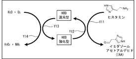
- Histamine oxidase purified by expressing histamine oxidase derived from Arthrobacter crystallopoietes KAIT-B-007 in recombinant Escherichia coli was used.
- histamine is oxidized, deaminated and decomposed by reacting with histamine oxidase (HOD) used as an enzyme.
- HOD histamine oxidase
- imidazole acetaldehyde is produced from histamine (arrow Y11), and HOD is displaced from the oxidized form to the reduced form by the reduction reaction (arrow Y12).
- oxygen is decomposed by the oxidation reaction of reduced HOD (arrow Y13), and hydrogen peroxide is generated from the decomposed oxygen and water (arrow Y14). That is, in response to the decomposition reaction of one molecule of histamine by HOD, one molecule each of histamine and oxygen disappears, and one molecule each of imidazole acetaldehyde and hydrogen peroxide is produced.
- the measuring device 3 is a device that measures the concentration of histamine by an electrochemical method by utilizing the reaction that histamine is decomposed by HOD.
- the measuring device 3 includes a sensor chip 3A and a main body 3B.
- the sensor chip 3A has a measuring unit 31 and an electrode 32.
- a thin film of HOD which is an enzyme (hereinafter referred to as "enzyme film 10"), is formed by applying a solution of histamine oxidase and glutaraldehyde as a cross-linking agent to the surface of the electrode 32 and drying the solution. Will be done.
- a solution (hereinafter referred to as "containing solution 30") in which a sample obtained from a living body such as fish meat is dissolved in a solvent is dropped onto the enzyme membrane 10 as a solution containing histamine.
- the measuring unit 31 can measure the current value of the current that flows when a voltage is applied to the electrode 32.
- the measured current value is output to the main body 3B.
- the main body 3B measures the concentration of histamine contained in the sample in the contained solution 30 based on the current value output from the sensor chip 3A.
- the main body unit 3B includes a CPU 21, a storage device 22, a display unit 23, an input unit 24, and an interface unit 25.
- the CPU 21 controls the entire measuring device 3.
- the storage device 22 stores programs executed by the CPU 21, various parameters, various tables, and measurement results.
- the display unit 23 displays the measured concentration of histamine.
- the input unit 24 receives an input operation for the main body unit 3B.
- the interface unit 25 communicates with the sensor chip 3A.
- the electrode 32 of the sensor chip 3A has electrodes 32B and 32C in addition to the electrode 32A having the enzyme film 10 on which the enzyme is formed on the surface.
- the electrode 32A is the working electrode
- the electrode 32B is the counter electrode
- the electrode 32C is the reference electrode.
- the CPU 21 (see FIG. 2) of the main body 3B outputs a signal specifying the voltage applied to the electrode 32 to the measuring unit 31 (see FIG. 2) of the sensor chip 3A.
- the measuring unit 31 applies a designated voltage to the electrode 32A with reference to the electrodes 32B and 32C in response to the signal.
- the oxygen remaining in the contained solution 30 permeates the enzyme membrane 10 of the electrode 32A and reaches the electrode 32A.
- Oxygen combines with the electrons supplied from the electrode 32A and decomposes (arrow Y23).
- applying a voltage to the electrode 32A by outputting a signal to the sensor chip 3A by the CPU 21 is paraphrased as "the CPU 21 applies a voltage to the electrode 32A".
- the measuring unit 31 outputs a signal indicating the current value of the current flowing in response to the application of the voltage to the electrode 32A to the main body unit 3B.
- the CPU 21 of the main body 3B can specify the concentration of decomposed oxygen, that is, the concentration of oxygen remaining in the contained solution 30, based on the current value indicated by the signal received from the sensor chip 3A. That is, the measuring device 3 measures the change in oxygen concentration in the contained solution 30 (arrow Y22) caused by the decomposition of histamine (arrow Y21) and the current value of the current generated by the electrolysis of oxygen (arrow Y23). It can be identified by measuring.
- the concentration of oxygen remaining in the contained solution 30 decreases as the histamine contained in the contained solution 30 is decomposed by the enzymatic reaction.
- the CPU 21 can measure the concentration of histamine contained in the contained solution 30 based on the current value indicated by the signal received from the sensor chip 3A.
- acquiring the current value by the CPU 21 receiving a signal from the sensor chip 3A is paraphrased as "the CPU 21 measures the current value of the current flowing through the electrode 32A".
- the concentration of oxygen in the contained solution 30 changes as the oxygen in the contained solution 30 is consumed by the enzymatic reaction (arrow Y22) and electrolysis (arrow Y23).
- the current value I of the current flowing when oxygen is electrolyzed can be derived as in the equation (1-1) by the simplified Butler-Volmer equation. That is, the current value I is proportional to the oxygen concentration C in the contained solution 30.
- V indicates the voltage applied to the electrode 32A.
- the coefficient ⁇ is a coefficient that fluctuates according to the activity of electrolysis.
- the coefficient ⁇ is a proportional coefficient that fluctuates according to the area and other characteristics of the electrode 32A.
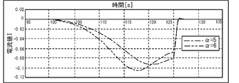
- the peak value of the current value I of the current flowing when the voltage applied to the electrode 32A is swept at 40 mV / s is compared for each of the coefficient ⁇ and the diffusion coefficient D of oxygen in the contained solution 30. ..
- the diffusion coefficient D correlates with the oxygen concentration C in the contained solution 30. 4 and 5 are graphs obtained by deriving the current value I of the current flowing when a sweep voltage is applied to the electrode 32A by simulation. The specific method of simulation will be described later. As shown in FIG. 4, there is no significant difference in the peak value of the current value I between the case where the coefficient ⁇ is 5 (dashed line) and the case where the coefficient ⁇ is 6 (dashed line). On the other hand, as shown in FIG. 5, there is a large difference in the peak value of the current value I between the case where the diffusion coefficient D is set to 0.5 (dashed line) and the case where the diffusion coefficient D is set to 0.1 (dashed line).
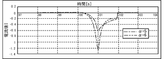
- the peak value of the current value I flowing when a pulse voltage is applied to the electrode 32A is compared for each value of the coefficient ⁇ and the diffusion coefficient D.
- 6 and 7 are graphs obtained by deriving the current value I of the current flowing when a pulse voltage is applied to the electrode 32A by simulation.
- FIG. 6 when the coefficient ⁇ is set to 5 (dashed-dotted line) and when the coefficient ⁇ is set to 6 (dashed-dotted line), a large difference occurs in the peak value of the current value I.
- FIG. 7 there is no significant difference in the peak value of the current value I between the case where the diffusion coefficient D is set to 0.5 (dashed line) and the case where the diffusion coefficient D is set to 0.1 (dashed line). ..
- the CPU 21 determines the concentration of histamine by performing the following main processing.
- the CPU 21 acquires the value 120s input by the user as the second elapsed time Tp (2) via the input unit 24 (S1). The details of the second elapsed time Tp (2) will be described later.
- the CPU 21 determines whether the contained solution 30 has been dropped onto the electrode 32A by the user (S11).
- the CPU 21 determines whether the contained solution 30 has been dropped onto the electrode 32A by the user (S11).
- the user performs an input operation to the effect that the dropping has been performed at the same time as the dropping via the input unit 24.
- the CPU 21 does not detect the input operation via the input unit 24, the CPU 21 determines that the contained solution 30 is not dropped on the electrode 32A (S11: NO).
- the CPU 21 returns the process to S11 and continuously determines whether or not the contained solution 30 has been dropped on the electrode 32A.
- the CPU 21 detects an input operation via the input unit 24, it determines that the contained solution 30 has been dropped onto the electrode 32A (S11: YES). In this case, the CPU 21 advances the process to S13.
- the CPU 21 determines that the contained solution 30 is dropped on the electrode 32A, more specifically, 0.3 s after the contained solution 30 is dropped on the electrode 32A (hereinafter referred to as the first elapsed time Tp (1)). Later, a voltage of ⁇ 600 mV (hereinafter referred to as the first voltage V (1)) is applied to the electrode 32A for 0.5 s (hereinafter referred to as the first application time Ta (1)) (see S13 and FIG. 9). At this time, the oxygen in the contained solution 30 is consumed by electrolysis.
- the time Tn required for the voltage of the electrode 32A to change from 0V to the first voltage V (1) is 0.3s (see FIG. 9).
- the time Tn is not limited to the value (0.3s) of the present embodiment, but is preferably any value between 0s and 3s. This is because, as described above, the consumption of oxygen due to electrolysis is suppressed so as not to affect the measurement accuracy.
- the first elapsed time Tp (1) shown in FIG. 9 is predetermined as a time within a range in which the progress of the reaction occurring after the dropping of the contained solution 30 with respect to the electrode 32A over time does not affect the measurement accuracy. More specifically, the first elapsed time Tp (1) is after the contained solution 30 is dropped on the electrode 32A and the decomposition reaction of histamine by HOD formed as the enzyme film 10 on the electrode 32A is started. Pre-defined as time.
- the first elapsed time Tp (1) is not limited to the value (0.3s) of the present embodiment, but is preferably any value between 0s and 30s.
- the amount of oxygen lost by electrolysis caused by the application of the voltage to the electrode 32A affects the measurement accuracy of the oxygen and histamine concentrations. It is predetermined as a value in the range that does not exist.
- the first voltage V (1) and the first application time Ta (1) are more specifically defined in advance as values that can recover the lost oxygen by the oxygen supplied by diffusion.
- the first voltage V (1) is not limited to the value (-600 mV) of the present embodiment, but is preferably any value between -1000 mV and -500 mV.
- the first application time Ta (1) is not limited to the value (0.5s) of the present embodiment, but is preferably any value between 0s and 3s.
- the CPU 21 measures the current value of the current flowing through the electrode 32A while the first voltage V (1) is applied to the electrode 32A by the processing of S13. (S15).
- the CPU 21 sets the integrated value of the current when the first voltage V (1) is applied to the electrode 32A or the integrated value of the current flowing through the electrode 32A while the first voltage V (1) is applied as the first current. It is measured as i 0 and stored in the storage device 22.
- the CPU 21 applies the first voltage V (1) to the electrode 32A by the processing of S13, and after the lapse of 120s acquired as the second elapsed time Tp (2) in the processing of S1, the first voltage V (1) A voltage is applied to the electrode 32A under the same conditions as the application conditions. More specifically, the CPU 21 applies a voltage of ⁇ 600 mV (hereinafter referred to as a second voltage V (2)) to the electrode 32A for 0.5 s (hereinafter referred to as a second application time Ta (2)) (S17). , See FIG. 9). At this time, the oxygen in the contained solution 30 is consumed by electrolysis.
- the second voltage V (2) and the second application time Ta (2) are equal to the first voltage V (1) and the first application time Ta (1) when applied to the electrode 32A by the processing of S13. Further, the time Tn required for the voltage of the electrode 32A to change from 0V to the second voltage V (2) is also 0.3s, and the first voltage V (1) is applied to the electrode 32A by the processing of S13. Equal to (see Figure 9).
- the first voltage V (1) and the second voltage V (2) may be different.
- the second voltage V (2) is not limited to the value of the present embodiment (-600 mV), but is preferably any value between -1000 mV and -500 mV.
- the first application time Ta (1) and the second application time Ta (2) may be different.
- the second application time Ta (2) is not limited to the value (0.5s) of the present embodiment, but is preferably any value between 0s and 3s.
- the time it takes for the voltage of the electrode 32A to change from 0V to the first voltage V (1) and the time it takes for the voltage of the electrode 32A to change from 0V to the second voltage V (2) are different. You may.
- the second elapsed time Tp (2) shown in FIG. 9 is the oxygen in the contained solution 30 after oxygen disappears by electrolysis when the first voltage V (1) is applied to the electrode 32A (see S13 and FIG. 8). It is supplied from the periphery of the electrode 32A to the electrode 32A by the diffusion phenomenon based on the concentration gradient of the above, and is predetermined as the time until the oxygen concentration recovers to the extent that the measurement accuracy is not affected.
- FIG. 10 is a graph derived by simulation of the relationship between the elapsed time immediately after the application of the first voltage V (1) and the oxygen concentration in the vicinity of the electrode 32A. From this graph, it can be seen that the oxygen concentration tends to decrease from the time when the first voltage V (1) is applied to the electrode 32A until about 120 s elapses. On the other hand, it can be seen that after about 120 s have passed since the first voltage V (1) was applied to the electrode 32A, the tendency of the oxygen concentration to decrease was suppressed and remained almost unchanged. That is, 120 seconds have passed since the first voltage V (1) was applied to the electrode 32A, and oxygen lost by electrolysis when the first voltage V (1) was applied is supplied to the electrode 32A by the diffusion phenomenon.
- 120 s is preset as the second elapsed time Tp (2).
- the second elapsed time Tp (2) is not limited to the value (120s) of the present embodiment, but is preferably any value between 10s and 600s.
- the appropriate value of the second elapsed time Tp (2) is related to both the recovery of oxygen disappearance by applying a voltage to the electrode 32A and the degree of progress of the reaction. Therefore, the appropriate value of the second elapsed time Tp (2) is determined by the user according to the diffusion coefficient D, the film thickness of the enzyme membrane 10, and the reaction rate by the enzyme.
- the user uses the time from the disappearance of oxygen due to the application of the first voltage V (1) to the electrode 32A until the oxygen concentration recovers according to the diffusion phenomenon in the contained solution 30 (hereinafter, "recovery time”). (Also referred to as)) was input to the input unit 24 as the second elapsed time Tp (2).
- the user can use the time from the start of the reaction rate of the decomposition reaction of histamine by HOD formed as the enzyme film 10 on the electrode 32A to the end of the reaction to the extent that the measurement accuracy is not affected (hereinafter referred to as “)”. , “Convergence time”) is longer than the recovery time, the convergence time may be input to the input unit 24 as the second elapsed time Tp (2).
- the CPU 21 measures the current value of the current flowing through the electrode 32A while the second voltage V (2) is applied to the electrode 32A by the processing of S17. (S19).
- the CPU 21 determines the integrated value of the current when the second voltage V (2) is applied to the electrode 32A or the integrated value of the current flowing through the electrode 32A while the second voltage V (2) is applied to the electrode 32A. It is measured as the second current i and stored in the storage device 22.
- FIG. 12 and 13 are graphs derived by simulation of the current value of the current flowing when a voltage is applied to the electrode 32A by the processing of S17.
- the CPU 21 measures the integrated value of the currents measured in the thick line frame as the second current i.
- the peak value of the current greatly differs depending on the difference in the coefficient ⁇ .
- the difference in the peak value of the current due to the difference in the coefficient ⁇ is minimized by measuring the integrated value of the current as the second current i.
- the CPU 21 reads out the first current i 0 measured by the processing of S15 and the second current i measured by the processing of S19 from the storage device 22 and acquires them.
- the CPU 21 can accurately measure the concentration of histamine in the contained solution 30 by normalizing the second current i using the first current i 0 by the following method (S21).
- the oxygen concentration when the first voltage V (1) is applied is expressed as c 0
- the oxygen concentration when the second voltage V (2) is applied is expressed as c.
- the ratio of the concentration c to the concentration c 0 is expressed as Rc.
- the first current i 0 and the second current i can be expressed as equations (1-2) and (1-3), respectively, based on the equation (1-1).
- the ratio Rc can be expressed as the formula (1-4) based on the formulas (1-2) and (1-3).
- the measurement of the first current i 0 and the second current i is performed with the same sample and the same electrode, and each ⁇ and ⁇ are equal, so that in the formula (1-1).
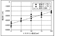
- FIG. 14 shows the measurement results showing the relationship between the first current i 0 (current at time 0 min) and the second current i (current at time 2 min) for each histamine concentration (0 ppm, 50 ppm, 100 ppm, 150 ppm). It is a graph which shows. More specifically, FIG. 14 shows the current obtained by applying a -600 mV square wave twice to the canned tuna boiled sample without histamine and the additives corresponding to 50 ppm, 100 ppm, and 150 ppm. It is a value graph. As shown in FIG. 14, the value of the first current i 0 is substantially constant (about -70000 nA) regardless of the concentration of histamine.
- the value of the second current i is about -60,000 nA when the histamine concentration is 0 ppm, about -30,000 nA when the histamine concentration is 50 ppm, and about -10000 nA when the histamine concentration is 100 ppm and 150 ppm.
- the second current i is a value corresponding to the concentration of histamine in the range where the concentration of histamine is at least 0 ppm to 100 ppm.
- the measuring device 3 stores in advance in the storage device 22 a linear function f indicating the relationship between the histamine concentration and the ratio Rc in the range of the histamine concentration in the range of 0 ppm to 100 ppm.
- the CPU 21 determines the concentration of histamine by applying the calculated ratio Rc to the linear function f stored in the storage device 22. This makes it possible to accurately measure the concentration of histamine regardless of the coefficients ⁇ and ⁇ of the contained solution 30.
- the CPU 21 ends the main process.
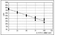
- FIG. 18 is a current value graph obtained by applying a square wave of ⁇ 600 mV twice to the canned tuna boiled sample without histamine and the additives equivalent to 25 ppm, 50 ppm, 75 ppm, and 100 ppm. Is.
- the second elapsed time Tp (2) was set to 120 s.
- the degree of fluctuation of the first current i0 with the increase in the concentration of histamine in the contained solution 30 is the first elapsed time.
- the time Tp (1) was larger than that in the cases of 0.3 s, 3.0 s, and 5.0 s (see FIGS. 16 (A) to 18 (A)).
- the slope of the linear curve that approximates the relationship between the histamine concentration and the ratio Rc ( i / i 0 ).
- the absolute value of is very small as compared with the case where the first elapsed time Tp (1) is 0.3 s, 3.0 s, 5.0 s (see FIGS. 16 (B) to 18 (B)), and is abbreviated. It became 0.
- the concentration of histamine can be appropriately specified based on the value of the ratio Rc by setting the first elapsed time Tp (1) to any value within the range of at least 0.3s to 5.0s. It became. On the other hand, when the first elapsed time Tp (1) was set to any value of 10 s or more, it was found that it was difficult to specify the histamine concentration based on the value of the ratio Rc. Further, the range of the first elapsed time Tp (1), which is the elapsed time from the dropping of the contained solution 30 on the electrode 32A and in which the progress of the histamine decomposition reaction due to the passage of time does not affect the measurement accuracy, is the present. It was clarified that it was 0.3 s to 5.0 s in the embodiment.
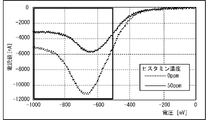
- FIG. 20 is a graph plotting the current value that flows when the voltage applied to the electrode 32A is swept. More specifically, FIG. 20 is a current value graph when swept from 0 mV to ⁇ 1000 mV at ⁇ 40 mV / sec for a canned tuna boiled sample without histamine and an additive corresponding to 50 ppm. As shown in FIG. 20, regardless of the concentration of histamine (0 ppm, 50 ppm) in the contained solution 30, a peak of the current value due to the electrolysis of oxygen was observed in the thick frame line in the figure. From this result, the concentration of histamine can be specified by the electrolysis of oxygen by setting the first voltage V (1) and the second voltage V (2) applied to the electrode 32A to a value larger than -500 mV as an absolute value. I understood.
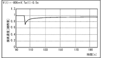
- 21 to 23 show the vicinity of the electrode 32A when the first voltage V (1) applied to the electrode 32A is ⁇ 700 mV (see FIG. 21), ⁇ 800 mV (see FIG. 22), and ⁇ 1000 mV (see FIG. 23). It is a graph derived from the time course of the oxygen concentration of.
- the time for applying the first voltage V (1) to the electrode 32A (first application time Ta (1)) is 0.5 s.
- the oxygen concentration in the vicinity of the electrode 32A can be satisfactorily recovered.
- the concentration of histamine can be appropriately specified based on the measured current value.
- the first voltage V (1) and the second voltage V (2) are made larger than -800 mV, the oxygen concentration in the vicinity of the electrode 32A cannot be recovered satisfactorily, so the histamine concentration is based on the measured current value. It turned out to be difficult to identify. Further, it was clarified that the range of the first voltage V (1) and the second voltage V (2) in which the amount of oxygen decomposed by electrolysis does not affect the measurement accuracy is -600 mV to -800 mV.
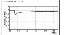
- FIG. 24 is a graph derived by simulation of the change over time in the oxygen concentration in the vicinity of the electrode 32A when the first voltage V (1) applied to the electrode 32A is ⁇ 700 mV.
- the difference from FIG. 21 is that the time for applying the first voltage V (1) to the electrode 32A (first application time Ta (1)) is 1.0 s.
- the recovery rate of the oxygen concentration after about 30 s from the application of the voltage was about 90%. Therefore, when the first application time Ta (1) is larger than at least 1.0 s, the oxygen concentration in the vicinity of the electrode 32A does not recover well even if time elapses from the application of the first voltage V (1). It turned out.
- the above results are similarly applied to the second application time Ta (2) when the voltage is applied to the electrode 32A from the second time onward.
- the oxygen concentration in the vicinity of the electrode 32A is good. It was clarified that the concentration of histamine can be appropriately specified based on the measured current value.
- the first application time Ta (1) and the second application time Ta (2) are made larger than 1.0 s, the oxygen concentration in the vicinity of the electrode 32A cannot be recovered satisfactorily, so that the oxygen concentration is not satisfactorily recovered. It turned out to be difficult to determine the concentration of histamine.
- the range of the first application time Ta (1) and the second application time Ta (2) which are the respective application times of the first voltage V (1) and the second voltage V (2) and do not affect the measurement accuracy, is , 0.5s to 1.0s.
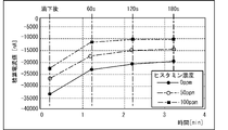
- the second voltage V (2) (-600 mV) is applied to the electrode 32A at the timing when the respective times of 60 s, 120 s, and 180 s have elapsed since the voltage of the first voltage V (1) was applied. It is a graph which showed the 2nd current i measured according to this for each concentration of histamine. More specifically, FIG. 25 was obtained by applying a square wave of ⁇ 600 mV four times at intervals of 60 seconds to the canned tuna boiled sample without histamine and the additives corresponding to 50 ppm and 100 ppm. It is a current value graph.
- the second current i was substantially the same. Therefore, it was found that the oxygen concentration in the vicinity of the electrode 32A is stabilized by setting the second elapsed time Tp (2), which is the elapsed time after applying the first voltage V (1), to 120 s or more. .. Therefore, it was found that the second current i can be measured accurately by setting the second elapsed time Tp (2) to 120 s or more, and the histamine concentration can be accurately specified based on the second current i. ..
- the simulation model focuses only on one dimension, that is, the direction (referred to as the y direction) orthogonal to the plane of the electrode 32A with the electrode 32A as the origin. It is assumed that there is no distribution of histamine and oxygen in the other directions (x direction, z direction).
- diffusion of oxygen is formulated as follows. According to Fick's first law of diffusion, diffusion is proportional to the concentration gradient and the diffusion area (unit amount 1) and can be expressed as follows. The diffusion coefficient is expressed as D, and the ratio of the diffusion coefficient of oxygen and histamine is expressed as g.
- the amount of oxygen when oxygen flows into a small area where the material balance is considered can be expressed by equation (2-1), and the amount of oxygen when oxygen flows out from the small area where the material balance is considered can be expressed by equation (2-1). It can be expressed by 2).
- the enzyme membrane 10 is made dimensionless by the film thickness L. Further, the amount of increase / decrease in a small area where the balance of supplies is considered due to the diffusion of oxygen can be expressed by Eq. (2-3).
- the amount of oxygen when histamine flows into a small area where the material balance is considered can be expressed by equation (2-4), and the amount of oxygen when histamine flows out from the small area where the material balance is considered can be expressed by equation (2--4). It can be expressed by 5).
- the amount of increase / decrease in a small area where the balance of supplies is considered due to the diffusion of histamine can be expressed by the formula (2-6).
- the amount of increase / decrease in the target substance, the amount at the time of outflow due to the diffusion of the target substance, the amount at the time of inflow due to the diffusion of the target substance, and the amount consumed by the enzymatic reaction of the target substance satisfy the relationship of the following formula (3). ..
- the amount of increase / decrease of the target substance is referred to as the amount of increase / decrease.
- the amount of the target substance at the time of outflow due to diffusion is referred to as diffusion outflow.
- diffusion inflow The amount at the time of inflow due to the diffusion of the target substance.
- reaction consumption The amount of the target substance consumed by the enzymatic reaction.
- Increase / decrease diffusion outflow-diffusion inflow-reaction consumption (3)
- Equation (2-1) By applying the equations (2-1) to (2-3) for oxygen to the equation (3), the equation (3-1) can be derived as the relational expression for oxygen. Equation (3-2) can be derived by dividing both sides by ⁇ y ⁇ t and taking the limit 0 for each of ⁇ y and ⁇ t.
- equation (3-3) can be derived as a relational expression for histamine.
- equation (3-4) can be derived by dividing both sides by ⁇ y ⁇ t and taking the limit 0 for each of ⁇ y and ⁇ t.
- Equations (3-3) and (3-4) are simultaneous second-order PDEs, and six boundary conditions are required to solve them. Moreover, it is very difficult to solve it analytically. Therefore, in this embodiment, the numerical solution method is applied.
- Equations (3-5) and (3-6) are called basic equations.
- equations (3-5) and (3-6) if the square of the film thickness of the enzyme membrane 10 and the diffusion coefficient are in an inverse proportional relationship, the same equation, that is, the same solution can be obtained. become. Therefore, for example, when there is a target substance having a small diffusion coefficient and cannot be measured, it may be possible to deal with it by reducing the film thickness of the enzyme membrane 10.
- Equation (4-4) corresponds to the fifth boundary condition.
- Equations (3-7), (3-8), (4-4), and (4-5) are simultaneous linear unsteady second-order PDEs that are difficult to solve analytically. On the other hand, if the steady state can be approximated, it can be solved.
- the Runge-Kutta method or the like is known as a method for solving a differential equation, but in the present embodiment, for the sake of simplification, the simplest sequential equation is adopted.
- the concentration of oxygen in the enzyme membrane 10 is expressed as, for example, C (t, x).
- the arguments are i, which indicates the number of t, and j, which indicates the number of x.
- the concentration of histamine in the enzyme membrane 10 is expressed as, for example, H (t, x).
- the arguments are i, which indicates the number of t, and j, which indicates the number of x.
- H ′′ and C ′′ with respect to y on the right side of the basic equation can be expressed by the following equations (5-3) and (5-4).
- H ′′ H (i-1, j + 1) + H (i-1, j-1) -2 ⁇ H (i-1, j) (5-4)
- C (i, j) and H (i, j) can be obtained by substituting each of the two equations into the basic equation and appropriately substituting the parameters.
- Equation (3-5) A simulation for deriving the graph shown in FIG. 11 will be described.
- equation (6-1) is derived by ignoring the term related to diffusion.
- equation (6-2) is derived by ignoring the term relating to diffusion.
- Equation (6-7) can be derived by analytically solving equation (6-6).
- Equation (6-8) can be derived by taking the limit where t is infinite with C 0 r> H.
- the convergence value of the normalized concentration c has a linear relationship with the initial histamine concentration H 0 .
- This linear relationship requires the reaction to proceed beyond a certain degree. In other words, the reaction must proceed to a range that does not affect the measurement accuracy.
- the time required for the reaction to proceed to a range that does not affect the measurement accuracy is such that if k is large, time t can be small, and if k is small, time t can be achieved. Must be large. Therefore, it can be seen that the convergence time is inversely proportional to the reaction rate.
- the second current i is not standardized and is used as it is as a current value affected by the coefficients ⁇ and ⁇ .
- FIG. 29 shows the relationship between the histamine concentration and the integrated value (without normalization) of the second current i when the conventional method is used.
- FIG. 30 shows the relationship between the histamine concentration and the ratio Rc showing the normalized value of the second current i when the method according to the present invention is used.
- the regression line was calculated for the integrated value and histamine concentration obtained in the two samples.
- R 2 0.83
- R 2 0.95. From this, it was confirmed that the measurement accuracy of the conventional method is the same as that of the sweep (see FIG. 28), but the accuracy is improved by using the method according to the present invention.
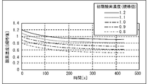
- FIG. 33 shows the time change of the oxygen concentration when the initial oxygen concentration (standard value) is 1.2, 1.1, 1.0, 0.9, and 0.8, respectively.
- FIG. 34 shows the time variation of the value obtained by normalizing the result of FIG. 33 at the initial oxygen concentration of 1.0. From the results of FIGS. 33 and 34, it was found that the time change of the oxygen concentration was aggregated regardless of the value of the initial oxygen concentration. Further, in FIGS. 33 and 34, the oxygen concentration is changed by ⁇ 20%. For example, the decrease in oxygen concentration is about 10% even at an altitude of 1000 m, and the decrease in atmospheric pressure is only about 10% even in a super-large typhoon. It was found that there is no practical problem with the difference in initial oxygen concentration.
- FIG. 35 shows the time variation of the integrated current value actually measured under the conditions of altitude 828 m / histamine concentration 0 ppm, altitude 10 m / histamine concentration 0 ppm, altitude 828 m / histamine concentration 50 ppm, and altitude 10 m / histamine concentration 50 ppm.
- the electrode 32 of the measuring device 3 has an enzyme film 10 on which an enzyme is formed on the surface. Histamine is produced as a decomposition product of IAA by reacting with an enzyme. The measuring device 3 electrolyzes the oxygen consumed in response to the decomposition of histamine to generate IAA by applying a voltage to the electrode 32A. The measuring device 3 can measure the concentration of histamine from the change in the concentration of oxygen by utilizing the reaction in which oxygen is electrolyzed by applying a voltage to the electrode 32A.
- the measuring device 3 measures the first current i 0 flowing through the electrode 32A in response to the application of the first voltage V (1) by the processing of S13 (S15), and applies the second voltage V (2) by the processing of S17.
- the second current i flowing through the electrode 32A is measured according to the above (S19).
- the measuring device 3 determines the concentration of histamine based on the first current i 0 and the second current i (S21). More specifically, the measuring device 3 measures the concentration of histamine based on the ratio Rc obtained by dividing the second current i by the first current i 0 .
- the measuring device 3 measures the histamine concentration based on the state before the reaction of histamine occurs. Since the measuring device 3 can eliminate the influence of the coefficients ⁇ and ⁇ by calculating the ratio Rc, it is possible to reduce the possibility that the measurement accuracy is lowered according to the fluctuation of the coefficients ⁇ and ⁇ . Therefore, the measuring device 3 can measure the concentration of histamine with higher accuracy.
- the measuring device 3 measures the integrated value of the current flowing while the first voltage V (1) is applied by the processing of S13 as the first current i 0 (S15).
- the measuring device 3 measures the integrated value of the current flowing while the second voltage V (2) is applied by the processing of S17 as the second current i (S19).
- the first current i 0 and the second current i measured in this case appropriately reflect the amount of oxygen electrolyzed by applying a voltage to the electrode 32A, and the difference in current value based on the difference in the coefficients ⁇ and ⁇ . The effect of is small. Therefore, the measuring device 3 can further reduce the possibility that the accuracy is lowered according to the fluctuation of the coefficients ⁇ and ⁇ , so that the histamine concentration can be measured with higher accuracy. Therefore, it is possible to reduce the possibility that an error occurs in the measurement result depending on the individual difference of the electrode 32A of the sensor chip 3A.
- the measuring device 3 determines the concentration of histamine by applying the calculated ratio Rc to the linear function f stored in the storage device 22 (S21). Therefore, the measuring device 3 can easily determine the concentration of histamine based on the ratio Rc.
- the first voltage V (1) applied in S13 and the second voltage V (2) applied in S17 are the same. Further, the measuring device 3 has a first application time Ta (1) for applying the first voltage V (1) in S13 and a second application time Ta (2) for applying the second voltage V (2) in S17. Are the same. Thereby, the measuring device 3 can specify the concentration of histamine with high accuracy based on the ratio Rc.
- the measuring device 3 determines whether or not the contained solution 30 has been dropped onto the electrode 32 (S11), and at the timing when it is determined that the contained solution 30 has been dropped (S11: YES), the first voltage V (1) with respect to the electrode 32A. ) Is applied (S13).
- the histamine in the contained solution 30 reacts between the time when the contained solution 30 is dropped onto the electrode 32 and the time when the application of the first voltage V (1) is started. The reaction amount of can be suppressed. Therefore, since the measuring device 3 can suppress the decomposition amount of histamine during this period, the concentration of histamine can be measured with higher accuracy.
- the electrode 32 of the sensor chip 3A has an electrode 32A as a working electrode, an electrode 32B as a counter electrode, and an electrode 32C as a reference electrode.
- the measuring device 3 applies a voltage to the electrode 32A based on the triode electrode method and measures the current. Therefore, the measuring device 3 can determine the physical quantity of the subject with higher accuracy than in the case where the voltage is applied to the electrodes and the current is measured based on the bipolar electrode method.
- the present invention is not limited to the above embodiment, and various modifications can be made.
- the measuring device 3 may be composed of only the sensor chip 3A.
- the measuring unit 31 may measure the current value of the current flowing when a voltage is applied to the electrode 32 and detect the concentration of histamine contained in the sample in the contained solution 30.
- the sensor chip 3A may display the detected concentration on a display unit (not shown). Further, the measuring device 3 may have a structure in which the sensor chip 3A and the main body 3B are integrated.
- the target for which the concentration is measured by the measuring device 3 is not limited to histamine.
- the measuring device 3 may detect an amine containing histamine. Further, the measuring device 3 may detect a non-proteinaceous substance contained in a sample obtained from a living body. Further, the measuring device 3 may measure the oxygen concentration. For example, the user may convert the oxygen concentration measured by the measuring device 3 into the histamine concentration by another device.
- the measuring device 3 may measure the concentration of hydrogen peroxide, which is generated by electrolysis of oxygen and whose amount increases. In this case, as hydrogen peroxide is generated at the interface of the electrode 32A, a concentration gradient of hydrogen peroxide is formed in the containing solution 30, and the hydrogen peroxide dissipates from the electrode 32A. For example, the user may convert the concentration of hydrogen peroxide measured by the measuring device 3 into the concentration of histamine by another device. Further, the measuring device 3 may directly measure the concentration of histamine based on the measured concentration of hydrogen peroxide.
- Another substance may be measured by changing the enzyme.
- the concentration of the subject may be measured by applying another reaction means without using an enzyme. Further, for example, it is not necessary to install a reaction promoting substance such as an enzyme on the electrode.
- the reaction accelerator may be mixed with the solution and then dropped onto the electrode to measure the time change.
- the measuring device 3 measured the concentration of histamine based on the ratio Rc obtained by dividing the second current i by the first current i 0 .
- the measuring device 3 may normalize (normalize) the second current i using the first current i 0 and measure the concentration of histamine by another method.
- the measuring device 3 may acquire a plurality of first currents i 0 and a plurality of second currents i by executing the main process a plurality of times, and measure the histamine concentration by statistically analyzing these. good.
- the measuring device 3 determined the concentration of histamine by applying the calculated ratio Rc to the linear function f stored in the storage device 22 (S21).
- the measuring device 3 may determine the concentration of histamine from the ratio Rc by another method.
- the measuring device 3 may store in the storage device 22 a table in which a plurality of candidates having a ratio Rc and a histamine concentration corresponding to each of the plurality of candidates are associated with each other.
- the measuring device 3 may determine the concentration of histamine associated with any of the plurality of candidates that most closely resembles the calculated ratio Rc as the concentration of histamine in the contained solution 30.
- the measuring device 3 measures the integrated value of the current flowing while the first voltage V (1) is applied as the first current i 0 (S15), and while the second voltage V (2) is applied. The integrated value of the current flowing through the current was measured as the second current i (S19). On the other hand, the measuring device 3 may measure the peak value of the current flowing through the electrode 32A when the first voltage V ( 1 ) is applied by the processing of S13 as the first current i0. Similarly, the measuring device 3 may measure the peak value of the current flowing through the electrode 32A when the second voltage V (2) is applied by the processing of S17 as the second current i.
- the measuring device 3 may have a dropping mechanism for dropping the contained solution 30 onto the electrode 32.
- the measuring device 3 may start applying the first voltage V (1) to the electrode 32A at the timing when the contained solution 30 is dropped onto the electrode 32 by the dropping mechanism (S13).
- the measuring device 3 may apply the second voltage V (2) to the electrode 32A more than once. For example, when the second voltage V (2) is applied m (m is an integer of 2 or more) times, as shown in FIG. 37, the measuring device 3 applies the second voltage V (2) m-1st time. Then, after the lapse of the third elapsed time Tp (3), the second voltage V (2) may be applied m times.
- the third elapsed time Tp (3) is a time until the change in oxygen concentration in the vicinity of the electrode 32A due to the application of the second voltage V (2) recovers to the extent that the diffusion of oxygen does not affect the measurement accuracy. Is stipulated.
- the third elapsed time Tp (3) is specifically 120 s, which is equal to the second elapsed time Tp (2).
- the value of the second voltage V (2) may be different each time it is applied m times.
- the value of the second elapsed time Tp (2) may be different each time the second voltage V (2) is applied m times.
- the third elapsed time Tp (3) may be a value different from the second elapsed time Tp (2).
- the value of the third elapsed time Tp (3) may be different for each interval when the second voltage V (2) is applied m times.
- a plurality of second elapsed time Tp (2) may be stored in advance in the ear storage device 22 of the measuring device 3.
- the CPU 21 may acquire an appropriate second elapsed time Tp (2) from the storage device 22 (S1) and perform the measurement according to the measurement conditions and the like. At this time, the CPU 21 may select whether to acquire the recovery time or the convergence time as the second elapsed time Tp (2) according to the measurement conditions and the like. Further, the CPU 21 may calculate and determine the optimum second elapsed time Tp (2) at the time of measurement according to the measurement conditions and the like.
- the measuring device 3 may measure the second current i each time the second voltage V (2) is applied m times. Further, the measuring device 3 may measure the concentration of histamine based on the relationship with the first current i 0 by statistically analyzing the second current i measured m times. Specifically, for example, the measuring device 3 linearly approximates the second current i measured m times to specify the linear function, and determines the histamine concentration based on the slope of the specified linear function. good.
- the change in oxygen concentration in the vicinity of the electrode 32A due to the application of the second voltage V (2) does not affect the measurement accuracy due to the diffusion of oxygen. It is not limited to the time it takes to recover to a certain degree.
- the second elapsed time Tp (2) and the third elapsed time Tp (3) are the times when the change in oxygen concentration in the vicinity of the electrode 32A due to the application of the voltage immediately before the electrode 32A is eliminated to the extent that the measurement accuracy is not affected. If it is within the range, it may be shorter than the time required for the change in oxygen concentration in the vicinity of the electrode 32A to recover.
- the ratio Rc after a long period of time may be predicted by using the change with time in the degree of decrease in the second current ratio Rc.
- the CPU 21 may determine the concentration of histamine based on the predicted ratio Rc. The details are as follows.
- FIG. 38 is a graph showing the time change of the current value and the current value ratio obtained by applying a square wave of ⁇ 600 mV four times at intervals of 60 seconds to the histamine-free sample of the canned tuna boiled sample.
- 38 (A) shows, when the first voltage V (1) and the second voltage V (2) are applied to the electrode 32A as shown in FIG. 37, after the first voltage V (1) is applied. It is a graph which showed the relationship between the elapsed time of 1 and the measured value (1st current i 0 or 2nd current i) of the current flowing through the electrode 32A at the time of voltage application.
- FIG. 38 (A) shows, when the first voltage V (1) and the second voltage V (2) are applied to the electrode 32A as shown in FIG. 37, after the first voltage V (1) is applied.
- It is a graph which showed the relationship between the elapsed time of 1 and the measured value (1st current i 0 or 2nd current i) of the current flowing through the electrode 32A at the time of voltage application
- t is the elapsed time since the first voltage V (1) was applied.
- the current flowing in response to the voltage applied to the electrode 32A after the elapsed time t after the first voltage V (1) is applied can be derived by the function F (t).
- the measuring device 3 can predict the convergence value of the current flowing in response to the voltage application to the electrode 32A before the current actually converges.
- the ratio Rc after the elapsed time t after the first voltage V (1) is applied can also be derived by the function F'(t).
- the measuring device 3 can predict the specification of the histamine concentration based on the ratio Rc by applying the function F'(t) before the current flowing in response to the voltage applied to the electrode 32A actually converges. It becomes. In this case, the histamine concentration can be accurately specified in a shorter time.
- FIG. 39 is a graph showing the relationship between the ratio Rc calculated based on the measured value of the second current i flowing when the second voltage V (2) is applied for the third time and the concentration of histamine. More specifically, FIG. 39 shows a short wave of -600 mV four times at 60 second intervals for the histamine-free and 25 ppm equivalent, 50 ppm equivalent, 75 ppm equivalent, and 100 ppm equivalent additives of the canned tuna boiled sample. It is a graph which plotted the ratio Rc at the time of application with respect to histamine concentration. The timing at which the current is measured to calculate the ratio Rc is 3 minutes after the first voltage V (1) is applied to the electrode 32A.
- the horizontal axis is defined as the x-axis and the vertical axis is defined as the y-axis
- the ratio Rc specified from the second current i flowing when the second voltage V (2) is applied after the lapse of 4 to 10 minutes is calculated based on the function y, and the calculated Rc is calculated. It is the result of evaluating the concentration of histamine predicted based on. More specifically, FIG. 40 is a simulation result (after 4 minutes) when the current value after 4 minutes is estimated from the actual measurement data for 3 minutes in FIG. 39. The result when the second voltage V (2) is applied after 3 minutes has passed is based on the measured value.
- the histamine sensitivity [/ ppm] is an index showing how much the ratio Rc changes per 1 ppm of histamine, and corresponds to the slope of the graph in FIG. 39.
- R 2 indicates a coefficient of determination obtained by squared the correlation coefficient R between the actual histamine concentration and the predicted histamine concentration, that is, the contribution rate.
- the concentration of histamine predicted based on the ratio Rc calculated based on the function y within the elapsed time range of 4 to 10 minutes is the actual concentration and accuracy of histamine. It turned out to be a good match. Further, from the result of R 2 , it was found that the histamine concentration can be specified with the highest accuracy when the elapsed time is 5 minutes because the value becomes the largest when the elapsed time is 5 minutes. Further, from the results of FIGS. 39 and 40, the second voltage V (2) is applied three times within 3 minutes from the application of the first voltage V (1), and the second current i is measured respectively. It was clarified that the ratio Rc can be calculated and the histamine concentration can be accurately specified without applying the second voltage V (2) after the fourth time.
- the electrode 32 has only a working electrode and a counter electrode, and does not have to have a reference electrode.
- the measuring device 3 may measure the concentration of histamine by applying a voltage to the electrodes and measuring the current based on the bipolar electrode method.
- Histamine is an example of the "subject” of the present invention.
- Oxygen is an example of the "measuring substance" of the present invention.
- the CPU 21 that performs the processing of S13 is an example of the "first application means” of the present invention.
- the CPU 21 that performs the processing of S15 is an example of the "first measuring means” of the present invention.
- the CPU 21 that performs the processing of S17 is an example of the “second application means” of the present invention.
- the CPU 21 that performs the processing of S19 is an example of the "second measuring means” of the present invention.
- the CPU 21 that performs the processing of S21 is an example of the "measurement means” of the present invention.
- the CPU 21 that performs the processing of S11 is an example of the "determining means” of the present invention.
- the treatment of S13 is an example of the "first application step” of the present invention.
- the treatment of S15 is an example of the "first measurement step” of the present invention.
- the treatment of S17 is an example of the “second application step” of the present invention.
- the treatment of S19 is an example of the "second measurement step” of the present invention.
- the process of S21 is an example of the "measurement step” of the present invention.
Abstract
Description
Arthrobacter crystallopoietes KAIT-B-007由来のヒスタミンオキシダーゼを遺伝子組み換え大腸菌にて発現させて精製したヒスタミンオキシダーゼが使用された。図1に示すように、ヒスタミンは、酵素として用いられるヒスタミンオキシダーゼ(HOD)と反応することにより、酸化及び脱アミノ化され分解される。この反応により、ヒスタミンからイミダゾールアセトアルデヒドが生成され(矢印Y11)、HODは還元反応により酸化型から還元型に変位する(矢印Y12)。又、還元型のHODの酸化反応(矢印Y13)により酸素が分解され、分解された酸素と水から過酸化水素が生成される(矢印Y14)。つまり、HODによるヒスタミン1分子の分解反応に応じ、ヒスタミン及び酸素が夫々1分子ずつ消失し、イミダゾールアセトアルデヒド及び過酸化水素が夫々1分子ずつ生成される。 <Decomposition reaction of histamine by enzyme>
Histamine oxidase purified by expressing histamine oxidase derived from Arthrobacter crystallopoietes KAIT-B-007 in recombinant Escherichia coli was used. As shown in FIG. 1, histamine is oxidized, deaminated and decomposed by reacting with histamine oxidase (HOD) used as an enzyme. By this reaction, imidazole acetaldehyde is produced from histamine (arrow Y11), and HOD is displaced from the oxidized form to the reduced form by the reduction reaction (arrow Y12). In addition, oxygen is decomposed by the oxidation reaction of reduced HOD (arrow Y13), and hydrogen peroxide is generated from the decomposed oxygen and water (arrow Y14). That is, in response to the decomposition reaction of one molecule of histamine by HOD, one molecule each of histamine and oxygen disappears, and one molecule each of imidazole acetaldehyde and hydrogen peroxide is produced.
図2に示すように、計測装置3は、HODによりヒスタミンが分解されるという反応を利用し、電気化学的手法によりヒスタミンの濃度を計測する装置である。計測装置3は、センサチップ3A及び本体部3Bを備える。センサチップ3Aは、測定部31及び電極32を有する。電極32の表面には、ヒスタミンオキシダーゼと、架橋剤としてのグルタルアルデヒドとを混合した溶液を塗布し、乾燥させることで、酵素であるHODの薄膜(以下、「酵素膜10」という。)が形成される。酵素膜10には、ヒスタミンを含む溶液として、魚肉等の生体から得られたサンプルを溶媒に溶解した溶液(以下、「含有溶液30」という。)が滴下される。測定部31は、電極32に電圧を印加したときに流れる電流の電流値を計測可能である。計測された電流値は本体部3Bに出力される。本体部3Bは、センサチップ3Aから出力される電流値に基づき、含有溶液30中のサンプルに含まれるヒスタミンの濃度を計測する。 <Outline of measuring
As shown in FIG. 2, the measuring
含有溶液30の酸素が酵素反応(矢印Y22)と電気分解(矢印Y23)によって消費されることに応じ、含有溶液30中の酸素の濃度は変化する。酸素が電気分解されるときに流れる電流の電流値Iは、簡易化したバトラーボルマーの式により、式(1-1)のように導出可能である。つまり、電流値Iは、含有溶液30中の酸素の濃度Cに比例する。
The concentration of oxygen in the contained
図8を参照し、計測装置3のCPU21によって実行されるメイン処理について説明する。CPU21は、計測装置3の電源投入時、記憶装置22に記憶されたプログラムを読み出して実行することによって、メイン処理を開始する。 <Main processing>
With reference to FIG. 8, the main process executed by the

図16~図19は、第1経過時間Tp(1)を0.3s(図16)、3.0s(図17)、5.0s(図18)、10s(図19参照)とした場合における第1電流i0及び第2電流iの積算値(図16(A)~図19(A)参照)、及び、比Rc(=i/i0)(図16(B)~図19(B)参照)をプロットしたグラフである。より詳細には、図16、図17、図19は、マグロ水煮缶詰サンプルのヒスタミン無添加と、50ppm相当、100ppm相当、150ppm相当添加品に対して、-600mVの短方形波を2回印加して得られた電流値グラフである。図18は、マグロ水煮缶詰サンプルのヒスタミン無添加と、25ppm相当、50ppm相当、75ppm相当、100ppm相当添加品に対して、-600mVの短方形波を2回印加して得られた電流値グラフである。なお、第2経過時間Tp(2)を120sとした。 <Evaluation of each parameter>
16 to 19 show the case where the first elapsed time Tp (1) is 0.3 s (FIG. 16), 3.0 s (FIG. 17), 5.0 s (FIG. 18), and 10 s (see FIG. 19). The integrated value of the first current i 0 and the second current i (see FIGS. 16 (A) to 19 (A)) and the ratio Rc (= i / i 0 ) (FIGS. 16 (B) to 19 (B)). )) Is a plot of the graph. More specifically, in FIGS. 16, 17, and 19, a square wave of -600 mV is applied twice to the canned tuna sample without histamine and the additives corresponding to 50 ppm, 100 ppm, and 150 ppm. It is a current value graph obtained by the above. FIG. 18 is a current value graph obtained by applying a square wave of −600 mV twice to the canned tuna boiled sample without histamine and the additives equivalent to 25 ppm, 50 ppm, 75 ppm, and 100 ppm. Is. The second elapsed time Tp (2) was set to 120 s.
図4~図7、図10、図12、図13で示したグラフを導出するためのシミュレーションについて説明する。電極32Aに電圧を印加することにより生じる現象は、次の3つに大別できる。
・酵素膜10内での酵素反応により、酸素及びヒスタミンが消費される。
・酵素膜10の周囲から酵素膜10に向けて、ヒスタミン及び酸素が拡散により輸送される。
・電極32Aにて酸素が電気分解されて消費され、電気分解に基づく電流が流れる。
上記の3つの現象の夫々を、以下に示す方法で定式化する。 <Simulation (when considering the diffusion of oxygen)>
A simulation for deriving the graphs shown in FIGS. 4 to 7, 10, 12, and 13 will be described. The phenomenon caused by applying a voltage to the
-Oxygen and histamine are consumed by the enzymatic reaction in the
Histamine and oxygen are transported by diffusion from the periphery of the
Oxygen is electrolyzed and consumed at the
Each of the above three phenomena is formulated by the method shown below.
シミュレーションのモデルは、1次元、即ち、電極32Aを原点として電極32Aの平面と直交する方向(y方向という。)のみに着目する。他の方向(x方向、z方向)には、ヒスタミン及び酸素の分布がないものとする。 <Consumption of histamine and oxygen by enzymatic reaction>
The simulation model focuses only on one dimension, that is, the direction (referred to as the y direction) orthogonal to the plane of the
酸素の消費量:-kHCΔyΔt
ヒスタミンの消費量:-γkHCΔyΔt
上記において、kは反応速度定数、Hはヒスタミンの重量濃度、Cは酸素の重量濃度、γは酸素とヒスタミンのモル分子量比率である。なお、溶媒が水であることを想定し、比重は1に設定されている。 In a small region (volume: Δy × 1 × 1) inside the
Oxygen consumption: -kHCΔyΔt
Histamine consumption: -γkHCΔyΔt
In the above, k is the reaction rate constant, H is the weight concentration of histamine, C is the weight concentration of oxygen, and γ is the molar molecular weight ratio of oxygen and histamine. Assuming that the solvent is water, the specific gravity is set to 1.
酵素膜10の外部において、ヒスタミン及び酸素の濃度は初期の状態で保たれる。一方、酵素膜10の内部では、酵素反応によってヒスタミン及び酸素が消費され、ヒスタミン及び酸素の濃度分布が生じる。このため、拡散によるヒスタミン及び酸素の移動が起こる。ここで、<酵素反応に依るヒスタミン及び酸素の消費量について>の場合と同様、酵素膜10の内部にある小さな領域(体積:Δy×1×1)におけるヒスタミン及び酵素の拡散を考える。 <Diffusion of histamine and oxygen>
Outside the


式(2-1)~(2-6)に基づき、ヒスタミン及び酸素(以下、対象物質と総称する。)の酵素反応による消費量と拡散とを統合した基礎方程式について、以下にて説明する。対象物質の増減量と、対象物質の拡散による流出時の量、対象物質の拡散による流入時の量、及び、対象物質の酵素反応による消費量とは、以下の式(3)の関係を満たす。但し、対象物質の増減量を、増減量と表記する。対象物質の拡散による流出時の量を、拡散流出と表記する。対象物質の拡散による流入時の量を、拡散流入と表記する。対象物質の酵素反応による消費量を、反応消費量と表記する。
増減量=拡散流出-拡散流入-反応消費量 (3) <Governing equation>
Based on the formulas (2-1) to (2-6), the basic equation that integrates the consumption and diffusion of histamine and oxygen (hereinafter collectively referred to as target substances) by the enzymatic reaction will be described below. The amount of increase / decrease in the target substance, the amount at the time of outflow due to the diffusion of the target substance, the amount at the time of inflow due to the diffusion of the target substance, and the amount consumed by the enzymatic reaction of the target substance satisfy the relationship of the following formula (3). .. However, the amount of increase / decrease of the target substance is referred to as the amount of increase / decrease. The amount of the target substance at the time of outflow due to diffusion is referred to as diffusion outflow. The amount at the time of inflow due to the diffusion of the target substance is referred to as diffusion inflow. The amount of the target substance consumed by the enzymatic reaction is referred to as the reaction consumption.
Increase / decrease = diffusion outflow-diffusion inflow-reaction consumption (3)


酸素の電気分解によって流れる電流は、簡易化したバトラーボルマー式に従い、式(4-1)を満たす。
The current flowing by the electrolysis of oxygen satisfies the equation (4-1) according to the simplified Butler-Volmer equation.


微分方程式の解法として、Runge-Kutta法等が知られているが、本実施形態では簡便化のため、最も簡単な逐次方程式とする方法をとる。酵素膜10中の酸素の濃度を、例えばC(t,x)と表記する。tが何番目であるかを示すiと、xが何番目であるかを示すjとを引数とする。同様に、酵素膜10中のヒスタミンの濃度を、例えばH(t,x)と表記する。tが何番目であるかを示すiと、xが何番目であるかを示すjとを引数とする。この場合、基礎方程式の左辺の、i番目のC,Hに関する時間微分C´、H´は、次の式(5-1)、(5-2)により表すことができる。
C´=C(i,j)-C(i-1,j) (5-1)
H´=H(i,j)-H(i-1,j) (5-2) <Numerical simulation>
The Runge-Kutta method or the like is known as a method for solving a differential equation, but in the present embodiment, for the sake of simplification, the simplest sequential equation is adopted. The concentration of oxygen in the
C'= C (i, j) -C (i-1, j) (5-1)
H'= H (i, j) -H (i-1, j) (5-2)
C´´={C(i-1,j+1)-C(i-1,j)}
-{C(i-1,j)-C(i-1,j-1)}
=C(i-1,j+1)+C(i-1,j-1)-2×C(i-1,j)
(5-3)
H´´=H(i-1,j+1)+H(i-1,j-1)-2×H(i-1,j)
(5-4)
各々2つの方程式を基礎方程式に代入し、適当にパラメータを代入することにより、C(i,j)及びH(i,j)を求めることができる。 Next, the second-order differential terms H ″ and C ″ with respect to y on the right side of the basic equation can be expressed by the following equations (5-3) and (5-4).
C ″ = {C (i-1, j + 1) -C (i-1, j)}
-{C (i-1, j) -C (i-1, j-1)}
= C (i-1, j + 1) + C (i-1, j-1) -2 x C (i-1, j)
(5-3)
H ″ = H (i-1, j + 1) + H (i-1, j-1) -2 × H (i-1, j)
(5-4)
C (i, j) and H (i, j) can be obtained by substituting each of the two equations into the basic equation and appropriately substituting the parameters.
基礎方程式には、印加電圧の変数があるが、このVを時間によって変化するとして時間変数V(t)とすると、任意のV(t)による酸素濃度、ヒスタミン濃度を計測可能である。又、次に示すように、酸素の電気分解により電流を計測可能である。 <Time change of applied voltage>
There is a variable of applied voltage in the basic equation, but if this V is changed with time and the time variable is V (t), the oxygen concentration and histamine concentration by any V (t) can be measured. Further, as shown below, the current can be measured by electrolysis of oxygen.
バトラーボルマー則により、酸素の電気分解により流れる電流は、式(4-1)により算出できる。この方程式により、電極32A上の酸素の濃度、及び、係数αが分かれば、電流を計算可能である。なお、係数αは、電極32Aの物性だけでなく、含有溶液30の特性(pHなど)によっても大きく変動する。一方、本実施形態によれば、比Rcを算出することにより、係数αの影響を排除できるので、電流値を精度良く特定し、ヒスタミンの濃度を正確に計測できる。 <Calculation of current flowing by electrolysis of oxygen>
According to Butler-Volmer's law, the current flowing due to the electrolysis of oxygen can be calculated by Eq. (4-1). If the concentration of oxygen on the
図11で示したグラフを導出するためのシミュレーションについて説明する。式(3-5)において、拡散に関する項を無視することにより、式(6-1)を導出する。同様に、式(3-6)において、拡散に関する項を無視することにより、式(6-2)を導出する。


A simulation for deriving the graph shown in FIG. 11 will be described. In equation (3-5), equation (6-1) is derived by ignoring the term related to diffusion. Similarly, in equation (3-6), equation (6-2) is derived by ignoring the term relating to diffusion.


本発明に係る手法に係る計測結果と、従来手法に係る計測結果との比較を行った。 <Evaluation>
The measurement result according to the method according to the present invention was compared with the measurement result according to the conventional method.
従来手法では、第2電流iを規格化せずにそのまま係数α、βの影響がある電流値として用いた。図26、図27は、規格化する前の第2電流i(2分後の電流値、図26参照)と、規格化された第2電流iを示す比Rc(2分後の電流値を第1電流i0で規格化、図27参照)との夫々のデータを示す。異なる2枚の酵素チップ(酵素チップA、B)を用い、魚肉抽出液中のヒスタミンを計測した。図26に示すように、第2電流iの規格化を行う前では、酵素チップの個体差や電流値のばらつきによって、ヒスタミンの推定精度に相当する決定係数R2=0.88となっている。一方、図27に示すように、第2電流iの規格化を行った場合には、R2=0.95となっており、計測精度が向上したことが確認された。 <
In the conventional method, the second current i is not standardized and is used as it is as a current value affected by the coefficients α and β. 26 and 27 show the ratio Rc (current value after 2 minutes) indicating the second current i before normalization (current value after 2 minutes, see FIG. 26) and the standardized second current i. Normalized with the first current i 0 , see FIG. 27) and the respective data are shown. Histamine in fish extract was measured using two different enzyme chips (enzyme chips A and B). As shown in FIG. 26, before the normalization of the second current i, the coefficient of determination R 2 = 0.88 corresponding to the estimation accuracy of histamine is obtained due to the individual difference of the enzyme chip and the variation of the current value. .. On the other hand, as shown in FIG. 27, when the second current i was standardized, R 2 = 0.95, and it was confirmed that the measurement accuracy was improved.
従来手法として、スイープによりヒスタミンの濃度を計測した。図28に示す例では、サンプルとしてマグロ生肉、及びマグロ水煮缶が用いられた。そして、これに対し、ヒスタミン無添加、25ppm、50ppm相当となるようにヒスタミンを添加し、計測を実施した。データは0mVから-800mVまで-20mV/secで電極の電圧をスイープした場合のピーク電流値をプロットした。又、2つのサンプルのデータに対して回帰直線を算出した。なお、決定係数R2=0.82となった。 <
As a conventional method, the concentration of histamine was measured by sweeping. In the example shown in FIG. 28, raw tuna meat and boiled tuna cans were used as samples. Then, on this, histamine was not added, histamine was added so as to be equivalent to 25 ppm and 50 ppm, and the measurement was carried out. The data plots the peak current value when the electrode voltage is swept from 0 mV to −800 mV at −20 mV / sec. In addition, a regression line was calculated for the data of the two samples. The coefficient of determination R 2 = 0.82.
本発明に係る手法により計測されたヒスタミンの濃度と、高速液体クロマトグラフィー(HPLC)にて計測されたヒスタミンの濃度とを比較した。サンプルとしてマグロ生肉を用いた場合の結果を、図31に示す。サンプルとしてマグロ水煮缶詰抽出液を用いた場合の結果を、図32に示す。この結果から、何れの決定係数R2も0.9より小さくなった。このことから、本発明に係る手法を適用することにより、ヒスタミンの濃度を高精度に計測できることが確認された。 <
The concentration of histamine measured by the method according to the present invention was compared with the concentration of histamine measured by high performance liquid chromatography (HPLC). The results when raw tuna meat is used as a sample are shown in FIG. 31. FIG. 32 shows the results when a canned tuna boiled extract was used as a sample. From this result, each coefficient of determination R2 was smaller than 0.9. From this, it was confirmed that the concentration of histamine can be measured with high accuracy by applying the method according to the present invention.
酸素濃度の時間変化を初期酸素濃度毎に評価した。図33は、初期酸素濃度(規格値)が1.2、1.1、1.0、0.9、0.8の夫々の場合における酸素濃度の時間変化を示す。図34は、図33の結果を初期酸素濃度1.0で規格化した値の時間変化を示す。図33、図34の結果から、酸素濃度の時間変化は、初期酸素濃度の値に依らず集約することが分かった。又、図33、図34では酸素濃度を±20%ずつ変化させているが、例えば標高1000mでも酸素濃度の低下は約10%、超大型台風でも気圧低下は約10%の低下に留まることから、初期酸素濃度の相違は実用上問題ないことが分かった。 <
The time change of oxygen concentration was evaluated for each initial oxygen concentration. FIG. 33 shows the time change of the oxygen concentration when the initial oxygen concentration (standard value) is 1.2, 1.1, 1.0, 0.9, and 0.8, respectively. FIG. 34 shows the time variation of the value obtained by normalizing the result of FIG. 33 at the initial oxygen concentration of 1.0. From the results of FIGS. 33 and 34, it was found that the time change of the oxygen concentration was aggregated regardless of the value of the initial oxygen concentration. Further, in FIGS. 33 and 34, the oxygen concentration is changed by ± 20%. For example, the decrease in oxygen concentration is about 10% even at an altitude of 1000 m, and the decrease in atmospheric pressure is only about 10% even in a super-large typhoon. It was found that there is no practical problem with the difference in initial oxygen concentration.
標高828m(気圧920hPa)と、標高10m(気圧1012hPa)との夫々における積算電流値/比Rcの時間変化を、ヒスタミンの濃度毎に評価した。図35は、標高828m/ヒスタミン濃度0ppm、標高10m/ヒスタミン濃度0ppm、標高828m/ヒスタミン濃度50ppm、及び標高10m/ヒスタミン濃度50ppmの夫々の条件で実測された積算電流値の時間変化を示す。図36は、標高828m/ヒスタミン濃度0ppm、標高10m/ヒスタミン濃度0ppm、標高828m/ヒスタミン濃度50ppm、及び標高10m/ヒスタミン濃度50ppmの夫々の条件で実測された比Rcの時間変化を示す。図34、図35の結果から、積算電流値及び比Rcは何れも一致しており、標高(気圧)の影響をほとんどうけないことが分かった。 <
The time change of the integrated current value / ratio Rc at the altitude of 828 m (atmospheric pressure 920 hPa) and the altitude of 10 m (atmospheric pressure 1012 hPa) was evaluated for each histamine concentration. FIG. 35 shows the time variation of the integrated current value actually measured under the conditions of altitude 828 m /
計測装置3の電極32は、酵素が製膜された酵素膜10を表面に有する。ヒスタミンは、酵素と反応することによってIAAが分解物として生成される。計測装置3は、ヒスタミンが分解されてIAAが生成されることに応じて消費される酸素を、電極32Aに対する電圧印加によって電気分解する。計測装置3は、電極32Aに対する電圧の印加によって酸素が電気分解する反応を利用し、酸素の濃度変化からヒスタミンの濃度を計測できる。 <Action and effect of this embodiment>
The
本発明は上記実施形態に限定されず、種々の変更が可能である。計測装置3は、センサチップ3Aのみで構成されてもよい。この場合、測定部31は、電極32に電圧を印加したときに流れる電流の電流値を計測し、含有溶液30中のサンプルに含まれるヒスタミンの濃度を検出してもよい。センサチップ3Aは、検出した濃度を、非図示の表示部に表示してもよい。更に、計測装置3は、センサチップ3A及び本体部3Bが一体化した構造を有していてもよい。 <Modification example>
The present invention is not limited to the above embodiment, and various modifications can be made. The measuring
ヒスタミンは、本発明の「被検体」の一例である。酸素は、本発明の「計測物質」の一例である。S13の処理を行うCPU21は、本発明の「第1印加手段」の一例である。S15の処理を行うCPU21は、本発明の「第1測定手段」の一例である。S17の処理を行うCPU21は、本発明の「第2印加手段」の一例である。S19の処理を行うCPU21は、本発明の「第2測定手段」の一例である。S21の処理を行うCPU21は、本発明の「計測手段」の一例である。S11の処理を行うCPU21は、本発明の「判定手段」の一例である。S13の処理は、本発明の「第1印加工程」の一例である。S15の処理は、本発明の「第1測定工程」の一例である。S17の処理は、本発明の「第2印加工程」の一例である。S19の処理は、本発明の「第2測定工程」の一例である。S21の処理は、本発明の「計測工程」の一例である。 <Others>
Histamine is an example of the "subject" of the present invention. Oxygen is an example of the "measuring substance" of the present invention. The
Claims (17)
- 被検体を含む溶液が電極に滴下されたことに応じて前記被検体に反応が起こることにより生じる計測物質の濃度の時間変化を、前記計測物質の電気分解によって生じる電流を計測することにより計測する計測装置であって、
前記電極に対する前記溶液の滴下後、前記反応の時間経過による進行が計測精度に影響しない範囲の第1経過時間後に、電気分解による前記計測物質の消失量又は増加量が計測精度に影響しない範囲の第1電圧を、計測精度に影響しない範囲の第1印加時間前記電極に印加する第1印加手段と、
前記第1印加手段による前記第1電圧の印加により流れる第1電流を測定する第1測定手段と、
前記第1電圧の印加による前記電極近傍の前記計測物質の濃度変化が、前記計測物質の拡散によって計測精度に影響しない程度まで回復するのに要する回復時間を、第2経過時間として取得する取得手段と、
前記第1印加手段により前記第1電圧が印加された後、前記取得手段により取得した第2経過時間の経過後に、少なくとも1回、電気分解による前記計測物質の消失量又は増加量が計測精度に影響しない範囲の第2電圧を、計測精度に影響しない範囲の第2印加時間前記電極に印加する第2印加手段と、
前記第2印加手段による前記第2電圧の印加により流れる第2電流を、少なくとも1回前記第2電圧が印加される毎に測定する第2測定手段と、
前記第1測定手段によって測定された前記第1電流を用いて、前記第2測定手段によって測定された前記第2電流を規格化し、前記反応に基づいて変化した前記計測物質の濃度又は前記被検体の濃度を計測する計測手段と、
を備えたことを特徴とする計測装置。 The time change in the concentration of the measurement substance caused by the reaction occurring in the subject in response to the solution containing the subject being dropped onto the electrode is measured by measuring the current generated by the electrolysis of the measurement substance. It ’s a measuring device,
After the first elapsed time within the range in which the progress of the reaction over time does not affect the measurement accuracy after the solution is dropped onto the electrode, the amount of disappearance or increase of the measured substance due to electrolysis does not affect the measurement accuracy. A first application means for applying the first voltage to the electrode for a first application time within a range that does not affect the measurement accuracy.
A first measuring means for measuring a first current flowing by applying the first voltage by the first applying means, and a first measuring means.
Acquisition means for acquiring the recovery time required for the concentration change of the measurement substance in the vicinity of the electrode due to the application of the first voltage to recover to the extent that the diffusion of the measurement substance does not affect the measurement accuracy as the second elapsed time. When,
After the first voltage is applied by the first application means and after the lapse of the second elapsed time acquired by the acquisition means, the amount of disappearance or increase of the measurement substance by electrolysis at least once is the measurement accuracy. A second application means for applying the second voltage in a range that does not affect the measurement accuracy to the electrode for a second application time in a range that does not affect the measurement accuracy.
A second measuring means for measuring the second current flowing due to the application of the second voltage by the second applying means at least once each time the second voltage is applied.
Using the first current measured by the first measuring means, the second current measured by the second measuring means is standardized, and the concentration of the measuring substance changed based on the reaction or the subject. A measuring means for measuring the concentration of
A measuring device characterized by being equipped with. - 前記取得手段は、
前記反応の反応速度に反比例する時間であって計測精度に影響しない程度まで前記反応が終了するまでの収束時間の方が、前記回復時間よりも長い場合、前記収束時間を前記第2経過時間として取得することを特徴とする請求項1に記載の計測装置。 The acquisition means
When the convergence time until the reaction is completed is longer than the recovery time, which is inversely proportional to the reaction rate of the reaction and does not affect the measurement accuracy, the convergence time is taken as the second elapsed time. The measuring device according to claim 1, wherein the measuring device is to be acquired. - 前記計測手段は、
前記第2測定手段によって測定された前記第2電流を、前記第1測定手段によって測定された前記第1電流で除算した算出値に基づいて、前記計測物質の濃度又は前記被検体の濃度を計測することを特徴とする請求項1又は2に記載の計測装置。 The measuring means is
The concentration of the measuring substance or the concentration of the subject is measured based on the calculated value obtained by dividing the second current measured by the second measuring means by the first current measured by the first measuring means. The measuring device according to claim 1 or 2, wherein the measuring device is characterized in that. - 前記算出値と濃度との関係を示す関数を記憶する記憶部を備え、
前記計測手段は、
前記算出値に前記関数を適用することによって、前記計測物質の濃度又は前記被検体の濃度を決定することを特徴とする請求項3に記載の計測装置。 A storage unit for storing a function indicating the relationship between the calculated value and the concentration is provided.
The measuring means is
The measuring device according to claim 3, wherein the concentration of the measuring substance or the concentration of the subject is determined by applying the function to the calculated value. - 前記第1測定手段は、
前記第1印加手段によって前記第1電圧が印加されている間に流れる電流の積算値を、前記第1電流として測定し、
前記第2測定手段は、
前記第2印加手段によって前記第2電圧が印加されている間に流れる電流の積算値を、前記第2電流として測定する
ことを特徴とする請求項1から4の何れかに記載の計測装置。 The first measuring means is
The integrated value of the current flowing while the first voltage is applied by the first application means is measured as the first current.
The second measuring means is
The measuring device according to any one of claims 1 to 4, wherein the integrated value of the current flowing while the second voltage is applied by the second applying means is measured as the second current. - 前記第1電圧と前記第2電圧とが同一であることを特徴とする請求項1から5の何れかに記載の計測装置。 The measuring device according to any one of claims 1 to 5, wherein the first voltage and the second voltage are the same.
- 前記第1印加時間と前記第2印加時間とが同一であることを特徴とする請求項1から6の何れかに記載の計測装置。 The measuring device according to any one of claims 1 to 6, wherein the first application time and the second application time are the same.
- 前記溶液が前記電極に滴下されたか判定する判定手段を備え、
前記第1印加手段は、
前記判定手段によって前記溶液が滴下されたと判断されたタイミングで、前記電極に対して前記第1電圧を印加することを特徴とする請求項1から7の何れかに記載の計測装置。 A means for determining whether or not the solution has been dropped onto the electrode is provided.
The first application means is
The measuring device according to any one of claims 1 to 7, wherein the first voltage is applied to the electrode at the timing when the determination means determines that the solution has been dropped. - 前記第2印加手段は、
前記第2電圧がm(mは2以上の整数)回印加される場合、m-1回目の前記第2電圧が印加された後、前記第2電圧の印加による前記電極近傍の前記計測物質の濃度変化が、前記計測物質の拡散によって計測精度に影響しない程度まで回復した第3経過時間の経過後に、m回目の前記第2電圧を印加することを特徴とする請求項1から8の何れかに記載の計測装置。 The second application means is
When the second voltage is applied m (m is an integer of 2 or more) times, after the second voltage is applied m-1st time, the measurement substance in the vicinity of the electrode is subjected to the application of the second voltage. Any of claims 1 to 8, wherein the second voltage is applied m times after the lapse of the third elapsed time in which the change in concentration has recovered to the extent that the diffusion of the measurement substance does not affect the measurement accuracy. The measuring device described in. - 前記第2印加手段によりm回印加される前記第2電圧の夫々の値のうち少なくとも一部の値が、他の値と相違することを特徴とする請求項9に記載の計測装置。 The measuring device according to claim 9, wherein at least a part of the values of the second voltage applied m times by the second applying means is different from the other values.
- 前記第2印加手段によりm回印加される前記第2電圧の夫々の前記第2印加時間の値のうち少なくとも一部の値が、他の値と相違することを特徴とする請求項9又は10に記載の計測装置。 9. The measuring device described in.
- 前記第2経過時間と前記第3経過時間とが同一であることを特徴とする請求項9から11の何れかに記載の計測装置。 The measuring device according to any one of claims 9 to 11, wherein the second elapsed time and the third elapsed time are the same.
- 前記電極は、酵素が製膜された酵素膜を表面に有し、
前記反応では、
前記被検体が前記酵素と反応することによって分解物が生成され、
前記第1印加手段、及び、前記第2印加手段は、
前記反応において前記分解物が生成されることに応じて消費される酸素を前記計測物質として、前記電極に対する電圧印加によって酸素を電気分解することを特徴とする請求項1から12の何れかに記載の計測装置。 The electrode has an enzyme membrane on which an enzyme is formed on the surface.
In the reaction,
When the subject reacts with the enzyme, a decomposition product is produced.
The first application means and the second application means
The invention according to any one of claims 1 to 12, wherein oxygen consumed in response to the formation of the decomposition product in the reaction is used as the measurement substance, and oxygen is electrolyzed by applying a voltage to the electrode. Measuring device. - 前記被検体がヒスタミンであり、前記分解物がイミダゾールアセトアルデヒドであることを特徴とする請求項13に記載の計測装置。 The measuring device according to claim 13, wherein the subject is histamine and the decomposition product is imidazole acetaldehyde.
- 前記電極は、作用極、対極、及び参照極を備えたことを特徴とする請求項1から14の何れかに記載の計測装置。 The measuring device according to any one of claims 1 to 14, wherein the electrode is provided with a working electrode, a counter electrode, and a reference electrode.
- 被検体を含む溶液が電極に滴下されたことに応じて前記被検体に反応が起こることにより生じる計測物質の濃度の時間変化を、前記計測物質の電気分解によって生じる電流を計測することにより計測する計測方法であって、
前記電極に対する前記溶液の滴下後、前記反応の時間経過による進行が計測精度に影響しない範囲の第1経過時間後に、電気分解による前記計測物質の消失量又は増加量が計測精度に影響しない範囲の第1電圧を、計測精度に影響しない範囲の第1印加時間前記電極に印加する第1印加工程と、
前記第1印加工程による前記第1電圧の印加により流れる第1電流を測定する第1測定工程と、
前記第1電圧の印加による前記電極近傍の前記計測物質の濃度変化が、前記計測物質の拡散によって計測精度に影響しない程度まで回復するのに要する回復時間を、第2経過時間として取得する取得工程と、
前記第1印加工程により前記第1電圧が印加された後、前記取得工程により取得した第2経過時間の経過後に、少なくとも1回、電気分解による前記計測物質の消失量又は増加量が計測精度に影響しない範囲の第2電圧を、計測精度に影響しない範囲の第2印加時間前記電極に印加する第2印加工程と、
前記第2印加工程による前記第2電圧の印加により流れる第2電流を、少なくとも1回前記第2電圧が印加される毎に測定する第2測定工程と、
前記第1測定工程によって測定された前記第1電流を用いて、前記第2測定工程によって測定された前記第2電流を規格化し、前記反応に基づいて変化した前記計測物質の濃度又は前記被検体の濃度を計測する計測工程と、
を備えたことを特徴とする計測方法。 The time change in the concentration of the measurement substance caused by the reaction occurring in the subject in response to the solution containing the subject being dropped onto the electrode is measured by measuring the current generated by the electrolysis of the measurement substance. It ’s a measurement method,
After the first elapsed time within the range in which the progress of the reaction over time does not affect the measurement accuracy after the solution is dropped onto the electrode, the amount of disappearance or increase of the measured substance due to electrolysis does not affect the measurement accuracy. A first application step of applying the first voltage to the electrode for a first application time within a range that does not affect the measurement accuracy, and
The first measurement step of measuring the first current flowing by the application of the first voltage by the first application step, and the first measurement step.
Acquisition step of acquiring the recovery time required for the concentration change of the measurement substance in the vicinity of the electrode due to the application of the first voltage to recover to the extent that the diffusion of the measurement substance does not affect the measurement accuracy as the second elapsed time. When,
After the first voltage is applied by the first application step and after the lapse of the second elapsed time acquired by the acquisition step, the amount of disappearance or increase of the measurement substance by electrolysis at least once is the measurement accuracy. A second application step of applying the second voltage in a range that does not affect the measurement accuracy to the electrode for a second application time in a range that does not affect the measurement accuracy.
A second measurement step of measuring the second current flowing due to the application of the second voltage by the second application step at least once each time the second voltage is applied.
Using the first current measured by the first measurement step, the second current measured by the second measurement step is standardized, and the concentration of the measurement substance changed based on the reaction or the subject. And the measurement process to measure the concentration of
A measurement method characterized by being equipped with. - 前記取得工程は、
前記反応の反応速度に反比例する時間であって計測精度に影響しない程度まで前記反応が終了するまでの収束時間の方が、前記回復時間よりも長い場合、前記収束時間を前記第2経過時間として取得することを特徴とする請求項16に記載の計測方法。 The acquisition process is
When the convergence time until the reaction is completed is longer than the recovery time, which is inversely proportional to the reaction rate of the reaction and does not affect the measurement accuracy, the convergence time is taken as the second elapsed time. The measurement method according to claim 16, wherein the measurement method is obtained.
Priority Applications (5)
| Application Number | Priority Date | Filing Date | Title |
|---|---|---|---|
| CN202080101768.1A CN115667903A (en) | 2020-12-21 | 2020-12-21 | Measuring device and measuring method |
| EP20966771.6A EP4266036A1 (en) | 2020-12-21 | 2020-12-21 | Measurement device and measurement method |
| PCT/JP2020/047591 WO2022137272A1 (en) | 2020-12-21 | 2020-12-21 | Measurement device and measurement method |
| JP2021557854A JP7090305B1 (en) | 2020-12-21 | 2020-12-21 | Measuring device and measuring method |
| US18/061,798 US20230098751A1 (en) | 2020-12-21 | 2022-12-05 | Measurement device and measurement method |
Applications Claiming Priority (1)
| Application Number | Priority Date | Filing Date | Title |
|---|---|---|---|
| PCT/JP2020/047591 WO2022137272A1 (en) | 2020-12-21 | 2020-12-21 | Measurement device and measurement method |
Related Child Applications (1)
| Application Number | Title | Priority Date | Filing Date |
|---|---|---|---|
| US18/061,798 Continuation US20230098751A1 (en) | 2020-12-21 | 2022-12-05 | Measurement device and measurement method |
Publications (1)
| Publication Number | Publication Date |
|---|---|
| WO2022137272A1 true WO2022137272A1 (en) | 2022-06-30 |
Family
ID=82155928
Family Applications (1)
| Application Number | Title | Priority Date | Filing Date |
|---|---|---|---|
| PCT/JP2020/047591 WO2022137272A1 (en) | 2020-12-21 | 2020-12-21 | Measurement device and measurement method |
Country Status (5)
| Country | Link |
|---|---|
| US (1) | US20230098751A1 (en) |
| EP (1) | EP4266036A1 (en) |
| JP (1) | JP7090305B1 (en) |
| CN (1) | CN115667903A (en) |
| WO (1) | WO2022137272A1 (en) |
Citations (8)
| Publication number | Priority date | Publication date | Assignee | Title |
|---|---|---|---|---|
| JPH04233446A (en) * | 1990-05-02 | 1992-08-21 | Siemens Ag | Electrochemical enzyme sensor |
| JP2009510434A (en) | 2005-09-30 | 2009-03-12 | バイエル・ヘルスケア・エルエルシー | Gated voltammetry |
| JP2010121948A (en) * | 2008-11-17 | 2010-06-03 | Tohoku Univ | Apparatus and method for measuring respiration activity of fertilized egg |
| JP2012008151A (en) * | 2005-09-30 | 2012-01-12 | Lifescan Inc | Method and device for quick electrochemical analysis |
| US20130277234A1 (en) * | 2010-12-22 | 2013-10-24 | Roche Diagnostics Operations, Inc. | Systems and methods to compensate for sources of error during electrochemical testing |
| JP2017037067A (en) * | 2015-08-10 | 2017-02-16 | アークレイ株式会社 | Measurement method, measurement device and measurement program of sensor using comb-type electrode |
| WO2018105454A1 (en) * | 2016-12-07 | 2018-06-14 | パナソニックIpマネジメント株式会社 | Electrochemical measuring method and electrochemical measuring device |
| JP2018173415A (en) * | 2007-12-10 | 2018-11-08 | アセンシア・ダイアベティス・ケア・ホールディングス・アーゲーAscensia Diabetes Care Holdings AG | Inclination base correction |
-
2020
- 2020-12-21 CN CN202080101768.1A patent/CN115667903A/en active Pending
- 2020-12-21 EP EP20966771.6A patent/EP4266036A1/en active Pending
- 2020-12-21 JP JP2021557854A patent/JP7090305B1/en active Active
- 2020-12-21 WO PCT/JP2020/047591 patent/WO2022137272A1/en active Application Filing
-
2022
- 2022-12-05 US US18/061,798 patent/US20230098751A1/en active Pending
Patent Citations (8)
| Publication number | Priority date | Publication date | Assignee | Title |
|---|---|---|---|---|
| JPH04233446A (en) * | 1990-05-02 | 1992-08-21 | Siemens Ag | Electrochemical enzyme sensor |
| JP2009510434A (en) | 2005-09-30 | 2009-03-12 | バイエル・ヘルスケア・エルエルシー | Gated voltammetry |
| JP2012008151A (en) * | 2005-09-30 | 2012-01-12 | Lifescan Inc | Method and device for quick electrochemical analysis |
| JP2018173415A (en) * | 2007-12-10 | 2018-11-08 | アセンシア・ダイアベティス・ケア・ホールディングス・アーゲーAscensia Diabetes Care Holdings AG | Inclination base correction |
| JP2010121948A (en) * | 2008-11-17 | 2010-06-03 | Tohoku Univ | Apparatus and method for measuring respiration activity of fertilized egg |
| US20130277234A1 (en) * | 2010-12-22 | 2013-10-24 | Roche Diagnostics Operations, Inc. | Systems and methods to compensate for sources of error during electrochemical testing |
| JP2017037067A (en) * | 2015-08-10 | 2017-02-16 | アークレイ株式会社 | Measurement method, measurement device and measurement program of sensor using comb-type electrode |
| WO2018105454A1 (en) * | 2016-12-07 | 2018-06-14 | パナソニックIpマネジメント株式会社 | Electrochemical measuring method and electrochemical measuring device |
Non-Patent Citations (1)
| Title |
|---|
| KARUBE, I. ; SATOH, I. ; ARAKI, Y. ; SUZUKI, S. ; YAMADA, H.: "Monoamine oxidase electrode in freshness testing of meat", ENZYME AND MICROBIAL TECHNOLOGY, STONEHAM, MA, US, vol. 2, no. 2, 1 April 1980 (1980-04-01), US , pages 117 - 120, XP023677922, ISSN: 0141-0229, DOI: 10.1016/0141-0229(80)90066-6 * |
Also Published As
| Publication number | Publication date |
|---|---|
| EP4266036A1 (en) | 2023-10-25 |
| US20230098751A1 (en) | 2023-03-30 |
| CN115667903A (en) | 2023-01-31 |
| JPWO2022137272A1 (en) | 2022-06-30 |
| JP7090305B1 (en) | 2022-06-24 |
Similar Documents
| Publication | Publication Date | Title |
|---|---|---|
| US20190150802A1 (en) | Sensitivity Calibration of In Vivo Sensors Used to Measure Analyte Concentration | |
| EP2193367B1 (en) | Method for correcting erroneous results of measurement in biosensors and apparatus using the same | |
| US9910966B2 (en) | System and method of increasing sample throughput | |
| RU2006138214A (en) | METHOD AND DEVICE FOR IMPLEMENTATION OF FUNCTIONS OF CORRECTION, BASED ON THE THRESHOLD VALUE | |
| RU2006134033A (en) | METABOLIC CONTROL, METHOD AND DEVICE FOR OBTAINING INDICATIONS OF DETERMINING HEALTH OF THE CONDITION OF A PERSON | |
| JP6228639B2 (en) | Extrapolation of interpolated sensor data to increase sample throughput | |
| WO2014167303A1 (en) | Sensor calibration method and apparatus | |
| CN111458395B (en) | Kalman filtering method and device for changing Q value and readable storage medium | |
| JP7090305B1 (en) | Measuring device and measuring method | |
| JP2018508020A (en) | Detecting temporary errors in body fluid samples | |
| US20180263529A1 (en) | Ketone Body Concentration Estimation Device, Method, and Computer-Readable Storage Medium | |
| CN114145738B (en) | Analyte concentration data generation method and device, and system for monitoring analyte level | |
| CN107810409B (en) | Method of correcting CREA sensors for calcium inhibition | |
| CN111326255A (en) | Blood glucose concentration correction method based on big data, storage medium and system | |
| CN107110813A (en) | The calibration concept for the ampere-type creatinine sensor being corrected to endogenous modulator | |
| US20230394359A1 (en) | Time series anomaly detection model training accelerator | |
| CN117309976A (en) | Method for measuring fluorine content by using fluorine ion selective electrode method | |
| CN112132716A (en) | Memory capacity analysis method and system based on big data | |
| KR101079790B1 (en) | The method for estimating the features of target material using kinetic changing information and the apparatus thereof | |
| JPWO2016076232A1 (en) | Equilibrium potential estimation method, equilibrium potential estimation device, concentration estimation device, program, medium, and blood glucose estimation device |
Legal Events
| Date | Code | Title | Description |
|---|---|---|---|
| ENP | Entry into the national phase |
Ref document number: 2021557854 Country of ref document: JP Kind code of ref document: A |
|
| 121 | Ep: the epo has been informed by wipo that ep was designated in this application |
Ref document number: 20966771 Country of ref document: EP Kind code of ref document: A1 |
|
| WWE | Wipo information: entry into national phase |
Ref document number: 2020966771 Country of ref document: EP |
|
| NENP | Non-entry into the national phase |
Ref country code: DE |
|
| ENP | Entry into the national phase |
Ref document number: 2020966771 Country of ref document: EP Effective date: 20230721 |