WO2022131078A1 - Input device, controller, and error detection method - Google Patents
Input device, controller, and error detection method Download PDFInfo
- Publication number
- WO2022131078A1 WO2022131078A1 PCT/JP2021/044961 JP2021044961W WO2022131078A1 WO 2022131078 A1 WO2022131078 A1 WO 2022131078A1 JP 2021044961 W JP2021044961 W JP 2021044961W WO 2022131078 A1 WO2022131078 A1 WO 2022131078A1
- Authority
- WO
- WIPO (PCT)
- Prior art keywords
- magnet
- sensor
- input device
- magnetic field
- operation unit
- Prior art date
Links
- 238000001514 detection method Methods 0.000 title claims description 24
- 230000005856 abnormality Effects 0.000 claims description 15
- 239000000463 material Substances 0.000 claims description 8
- 238000012545 processing Methods 0.000 description 24
- 238000000034 method Methods 0.000 description 13
- 230000008859 change Effects 0.000 description 11
- 238000012986 modification Methods 0.000 description 8
- 230000004048 modification Effects 0.000 description 8
- 238000004891 communication Methods 0.000 description 6
- 230000004907 flux Effects 0.000 description 4
- 230000008569 process Effects 0.000 description 4
- 238000013459 approach Methods 0.000 description 2
- 230000000052 comparative effect Effects 0.000 description 2
- 239000000428 dust Substances 0.000 description 2
- 210000003811 finger Anatomy 0.000 description 2
- 238000005259 measurement Methods 0.000 description 2
- 229910052751 metal Inorganic materials 0.000 description 2
- 239000002184 metal Substances 0.000 description 2
- XLYOFNOQVPJJNP-UHFFFAOYSA-N water Substances O XLYOFNOQVPJJNP-UHFFFAOYSA-N 0.000 description 2
- 230000001154 acute effect Effects 0.000 description 1
- 238000012790 confirmation Methods 0.000 description 1
- 238000013461 design Methods 0.000 description 1
- 238000006073 displacement reaction Methods 0.000 description 1
- 239000000314 lubricant Substances 0.000 description 1
- 230000007257 malfunction Effects 0.000 description 1
- 238000004519 manufacturing process Methods 0.000 description 1
- 229910001172 neodymium magnet Inorganic materials 0.000 description 1
- 239000011347 resin Substances 0.000 description 1
- 229920005989 resin Polymers 0.000 description 1
- 230000004044 response Effects 0.000 description 1
- 238000004092 self-diagnosis Methods 0.000 description 1
- 238000000926 separation method Methods 0.000 description 1
- 238000012360 testing method Methods 0.000 description 1
- 210000003813 thumb Anatomy 0.000 description 1
- 229910000859 α-Fe Inorganic materials 0.000 description 1
Images


Classifications
-
- A—HUMAN NECESSITIES
- A63—SPORTS; GAMES; AMUSEMENTS
- A63F—CARD, BOARD, OR ROULETTE GAMES; INDOOR GAMES USING SMALL MOVING PLAYING BODIES; VIDEO GAMES; GAMES NOT OTHERWISE PROVIDED FOR
- A63F13/00—Video games, i.e. games using an electronically generated display having two or more dimensions
- A63F13/20—Input arrangements for video game devices
- A63F13/21—Input arrangements for video game devices characterised by their sensors, purposes or types
-
- A—HUMAN NECESSITIES
- A63—SPORTS; GAMES; AMUSEMENTS
- A63F—CARD, BOARD, OR ROULETTE GAMES; INDOOR GAMES USING SMALL MOVING PLAYING BODIES; VIDEO GAMES; GAMES NOT OTHERWISE PROVIDED FOR
- A63F13/00—Video games, i.e. games using an electronically generated display having two or more dimensions
- A63F13/20—Input arrangements for video game devices
- A63F13/24—Constructional details thereof, e.g. game controllers with detachable joystick handles
-
- G—PHYSICS
- G05—CONTROLLING; REGULATING
- G05G—CONTROL DEVICES OR SYSTEMS INSOFAR AS CHARACTERISED BY MECHANICAL FEATURES ONLY
- G05G9/00—Manually-actuated control mechanisms provided with one single controlling member co-operating with two or more controlled members, e.g. selectively, simultaneously
- G05G9/02—Manually-actuated control mechanisms provided with one single controlling member co-operating with two or more controlled members, e.g. selectively, simultaneously the controlling member being movable in different independent ways, movement in each individual way actuating one controlled member only
- G05G9/04—Manually-actuated control mechanisms provided with one single controlling member co-operating with two or more controlled members, e.g. selectively, simultaneously the controlling member being movable in different independent ways, movement in each individual way actuating one controlled member only in which movement in two or more ways can occur simultaneously
- G05G9/047—Manually-actuated control mechanisms provided with one single controlling member co-operating with two or more controlled members, e.g. selectively, simultaneously the controlling member being movable in different independent ways, movement in each individual way actuating one controlled member only in which movement in two or more ways can occur simultaneously the controlling member being movable by hand about orthogonal axes, e.g. joysticks
-
- G—PHYSICS
- G06—COMPUTING; CALCULATING OR COUNTING
- G06F—ELECTRIC DIGITAL DATA PROCESSING
- G06F3/00—Input arrangements for transferring data to be processed into a form capable of being handled by the computer; Output arrangements for transferring data from processing unit to output unit, e.g. interface arrangements
- G06F3/01—Input arrangements or combined input and output arrangements for interaction between user and computer
- G06F3/03—Arrangements for converting the position or the displacement of a member into a coded form
- G06F3/033—Pointing devices displaced or positioned by the user, e.g. mice, trackballs, pens or joysticks; Accessories therefor
- G06F3/0338—Pointing devices displaced or positioned by the user, e.g. mice, trackballs, pens or joysticks; Accessories therefor with detection of limited linear or angular displacement of an operating part of the device from a neutral position, e.g. isotonic or isometric joysticks
-
- H—ELECTRICITY
- H01—ELECTRIC ELEMENTS
- H01H—ELECTRIC SWITCHES; RELAYS; SELECTORS; EMERGENCY PROTECTIVE DEVICES
- H01H25/00—Switches with compound movement of handle or other operating part
- H01H25/04—Operating part movable angularly in more than one plane, e.g. joystick
-
- H—ELECTRICITY
- H01—ELECTRIC ELEMENTS
- H01H—ELECTRIC SWITCHES; RELAYS; SELECTORS; EMERGENCY PROTECTIVE DEVICES
- H01H25/00—Switches with compound movement of handle or other operating part
- H01H25/06—Operating part movable both angularly and rectilinearly, the rectilinear movement being along the axis of angular movement
Definitions
- the present invention relates to an input device, a controller and an error detection method.
- Patent Document 1 Japanese Patent Application Laid-Open No. 2012-221342
- Patent Document 2 Japanese Patent Application Laid-Open No. 2013-065398
- Patent Document 3 Japanese Patent Application Laid-Open No. 2016-207634
- a magnet that generates a magnetic field
- a sensor for detecting the magnetic field generated by the magnet
- a magnet moving unit for moving the position of the magnet in a predetermined first plane.
- the magnet includes the first magnet and the second magnet, the sensor is provided in a region different from the region where the magnet moves in the top view with respect to the first plane, and the magnet moving portion is provided in the first plane.
- the first magnet is moved in a predetermined first direction
- the second magnet is moved in a second direction different from the first direction in the first plane, and the first direction and the second direction are the first. Orthogonal in one plane, the sensor provides an input device commonly provided for the first and second magnets.
- a controller provided with the input device according to the first aspect of the present invention is provided.
- a third aspect of the present invention is an error detection method for an input device including a magnet that moves in response to an operation of the operation unit and a sensor for detecting a magnetic field generated by the magnet, wherein the operation unit is previously operated.
- An abnormality in the orientation of the magnet, an abnormality in the strength of the magnet, or an abnormality in the input device based on the stage of operating with a predetermined pattern, the stage of acquiring magnetic field data based on a predetermined pattern, and the acquired magnetic field data.
- an error detection method including a step of determining at least one of whether or not a mounting error is within an allowable range.
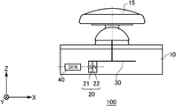
- An example of the side view of the input device 100 is shown.
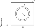
- An example of the top view of the input device 100 is shown.
- An example of a side view of the input device 100 in a state where the operation unit 15 is tilted is shown.
- An example of the operation of the input device 100 in a state where the operation unit 15 is tilted is shown.
- An example of the operation of the input device 100 is shown.
- An example of the sensor 40 capable of detecting a three-axis magnetic field is shown.
- a modification of the input device 100 is shown.
- a modification of the input device 100 is shown.
- a modification of the input device 100 is shown.
- FIG. 1A shows an example of a side view of the input device 100.
- the input device 100 includes a housing 10, an operation unit 15, a magnet 20, a magnet moving unit 30, and a sensor 40.
- the input device 100 is a device mounted on a controller for a video game or the like and for inputting a signal corresponding to the operation of the operation unit 15.
- the plane on which the operation unit 15 moves is defined as the first plane (that is, the XY plane), and the direction perpendicular to the first plane (Z-axis direction) is defined as the height direction of the input device 100.
- the viewpoint from the positive side to the negative side in the Z-axis direction may be referred to as a top view.
- the housing 10 houses the magnet 20, the magnet moving portion 30, and the sensor 40.
- the shape of the housing 10 in this example is a rectangular parallelepiped, but the shape is not limited to this.
- the housing 10 has a shape that can be embedded depending on the controller to be mounted.
- the operation unit 15 is a protruding member that can be operated up, down, left, and right.
- the operation unit 15 can be tilted in any direction by operation.
- the operation unit 15 operates the magnet 20 by the magnet moving unit 30 according to the tilting operation.
- the operation unit 15 may be pushed in the Z-axis direction in addition to the up / down / left / right tilting operation corresponding to the XY plane.
- the material of the operating unit 15 is an insulating resin.
- the magnet 20 has a first pole 21 and a second pole 22, and generates a magnetic field having a predetermined size.
- the first pole 21 is the S pole and the second pole 22 is the N pole.
- the magnet 20 may be a magnet such as a neodymium magnet or a ferrite magnet.
- the magnet 20 is fixed to the end of the magnet moving portion 30.
- the first pole 21 is arranged at a position close to the sensor 40
- the second pole 22 is arranged at a position away from the sensor 40, but the first pole 21 and the second pole 22 are conversely the same. It may be arranged.
- the shape of the magnet 20 in this example is a rectangular parallelepiped, but the shape is not limited to this.
- the first pole 21 and the second pole 22 are arranged in a predetermined direction in the XY plane.
- the first pole 21 and the second pole 22 may be arranged in the X-axis direction or the Y-axis direction.
- the first pole 21 and the second pole 22 may be arranged in the Z-axis direction.
- the X-axis direction is an example of the first direction
- the Y-axis direction is an example of the second direction.
- the magnet moving unit 30 moves the magnet 20 in conjunction with the operation by the operating unit 15.
- the magnet moving unit 30 of this example moves the magnet 20 in a direction and a position corresponding to the inclination of the operating unit 15.
- the magnet moving unit 30 of this example functions as a slider that converts the tilting operation of the operating unit 15 into the movement of the magnet 20 in the XY plane.
- the sensor 40 detects the magnetic field generated by the magnet 20.
- the sensor 40 of this example outputs a change in the magnetic field according to the movement of the magnet 20 as magnetic field data. By processing the magnetic field data output by the sensor 40, the movement of the magnet 20 can be detected.
- the sensor 40 may be a 3-axis magnetic sensor capable of detecting a 3-axis magnetic field, or may be a 1-axis or 2-axis magnetic sensor.
- the sensor 40 of this example is arranged on the bottom surface of the housing 10, it may be arranged above the bottom surface of the housing 10. When the sensor 40 is arranged on the bottom surface of the housing 10, the workability at the time of mounting is more likely to be improved than when the sensor 40 is arranged on the side surface of the housing 10.
- FIG. 1B shows an example of a top view of the input device 100.
- the shape of the operation unit 15 is substantially circular in the top view.
- the operation unit 15 of this example has a shape suitable for being operated by a finger, but the shape of the operation unit 15 is not limited to this example.
- the center C1 refers to the center position of the operation unit 15 at the reference position.
- the reference position of the operation unit 15 is the position of the operation unit 15 in a non-tilted state.
- the center C1 of the operation unit 15 may be arranged so as to coincide with the center of the housing 10 in the XY plane, or may be arranged so as to be offset from the center of the housing 10 in the XY plane.
- FIG. 2A shows an example of a side view of the input device 100 in a state where the operation unit 15 is tilted.
- the input device 100 of this example shows a state in which the operation unit 15 is tilted to the negative side in the X-axis direction.
- the magnet 20 moves to the positive side in the X-axis direction and slides in a direction away from the sensor 40.
- the sensor 40 acquires magnetic field data of a magnetic field weakened by the separation of the magnet 20.
- the input device 100 can know that the operation unit 15 is tilted to the negative side in the X-axis direction.
- FIG. 2B shows an example of the operation of the input device 100 in a state where the operation unit 15 is tilted.
- the input device 100 of this example shows a state in which the operation unit 15 is tilted to the positive side in the X-axis direction.
- the magnet 20 moves to the negative side in the X-axis direction and slides in a direction approaching the sensor 40.
- the sensor 40 acquires the magnetic field data of the magnetic field strengthened by the magnet 20 approaching.
- the input device 100 can know that the operation unit 15 is tilted to the positive side in the X-axis direction.
- the distance between the magnet 20 and the sensor 40 is set so that the sensor 40 can detect the change in the magnetic field generated by the magnet 20 even if the distance changes due to the tilting operation of the operation unit 15.
- the distance between the magnet 20 and the sensor 40 may be appropriately adjusted according to the magnitude of the magnetic field generated by the magnet 20, the characteristics required for the input device 100, the measurement range of the sensor 40, and the like.
- the input device 100 of this example is a non-contact type that detects magnetic field data corresponding to the tilting operation of the operation unit 15 by magnetic detection using the sensor 40, the sensor unit and the movable unit are non-contact, and both are non-contact. No mechanical wear occurs between parts. Further, since the configuration for detecting magnetic data has dust resistance and water resistance that are not easily affected by dust and water, there is no problem even if a lubricant or the like for smoothly moving a moving portion is injected. In this example, the case where the operation unit 15 moves the magnet 20 by the magnet moving unit 30 according to the component tilted in the X-axis direction has been described, but the same applies to other directions such as the Y-axis direction. It's okay.
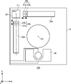
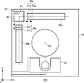
- FIG. 3A is a top view of the input device 100 showing the internal structure of the housing 10.
- the input device 100 of this example detects the movement of two magnets 20 moving in the X-axis direction or the Y-axis direction with one sensor 40.
- the input device 100 of this example includes two magnets 20a and a magnet 20b, and two magnet moving portions 30a and a magnet moving portion 30b.
- the magnet 20a is an example of the first magnet.
- the magnet 20b is an example of the second magnet.
- the input device 100 of this example includes a detection unit 50.
- the housing 10 has a substantially square shape in the XY plane.
- a magnet 20, a magnet moving unit 30, a sensor 40, and a detection unit 50 are arranged around an operation unit 15 provided near the center of the housing 10.
- the layout inside the housing 10 is not limited to this example, and may be changed in consideration of wiring for connecting the sensor 40 or the detection unit 50 to the outside.
- the magnet moving portion 30a moves the magnet 20a in the X-axis direction in the XY plane.
- the magnet moving portion 30a of this example slides the magnet 20a in the X-axis direction in conjunction with the movement of the operating portion 15 in the X-axis direction.
- the magnet moving portion 30a of this example is arranged along the positive side of the housing 10 in the Y-axis direction with respect to the center C1 of the operating portion 15.
- the magnet moving portion 30b moves the magnet 20b in the Y-axis direction on the XY plane.
- the magnet moving portion 30b of this example slides the magnet 20b in the Y-axis direction in conjunction with the movement of the operating portion 15 in the Y-axis direction.
- the magnet moving portion 30b of this example is arranged along the negative side of the housing 10 in the X-axis direction with respect to the center C1 of the operating portion 15.
- the first direction (that is, the X-axis direction) and the second direction (that is, the Y-axis direction) are orthogonal to each other in the first plane (that is, the XY plane).
- the angle formed by the first direction and the second direction may be an acute angle or an obtuse angle. Even in such a case, the state of the operation unit 15 can be acquired from the magnetic field data by changing the method of processing the magnetic field data of the sensor 40.
- the sensor 40 is commonly provided on the magnet 20a and the magnet 20b. That is, the sensor 40 of this example detects a magnetic field corresponding to the position of the magnet 20a and a magnetic field corresponding to the position of the magnet 20b, respectively.
- the sensor 40 is provided on the negative side of the magnet moving portion 30a in the X-axis direction and on the positive side of the magnet moving portion 30b in the Y-axis direction. For example, the sensor 40 detects the position of the magnet 20a from the change in the magnetic field in the X-axis direction, and detects the position of the magnet 20b from the change in the magnetic field in the Y-axis direction.
- the sensor 40 of this example is provided at the intersection P1 between the first direction in which the magnet 20a moves and the second direction in which the magnet 20b moves in the top view.
- the sensor 40 may be arranged at the center of the intersection P1 or may be arranged so as to include at least the intersection P1 in the top view.
- the input device 100 of this example can realize the miniaturization of the input device 100 by providing the sensor 40 in common to the plurality of magnets 20.
- the sensor 40 of this example is provided in a region different from the region where the magnet 20 moves in the top view.
- the sensor 40 is not provided directly below the operation unit 15 in the top view, but is provided at a position deviated from the center C1 in the XY plane. Therefore, the input device 100 is less susceptible to the pushing operation of the operation unit 15 in the Z-axis direction. As a result, the input device 100 of this example does not need to be thicker than the pushing operation in the Z-axis direction, so that the thickness can be reduced.
- the sensor when the sensor is provided below the center C1 of the operation unit 15, it may be affected by the pushing operation of the operation unit 15 in the Z-axis direction, and it is difficult to reduce the thickness.
- the detection unit 50 detects a component in the Z-axis direction corresponding to the pushing operation of the operation unit 15.
- the detection unit 50 includes a tact switch for push detection, and outputs detection data according to the pushing operation. If the pushing operation of the operation unit 15 is not detected, the detection unit 50 may be omitted.
- the detection data from the detection unit 50 may be processed by the same processing unit as the magnetic field data processing unit of the sensor 40.
- the first pole 21a is arranged at a position close to the sensor 40, and the second pole 22a is arranged at a position away from the sensor 40.
- the second pole 22b is arranged at a position close to the sensor 40, and the first pole 21b is arranged at a position away from the sensor 40. That is, in the input device 100 of this example, the attractive force arrangement is such that the magnets 20 attract each other when they approach the sensor 40, but the repulsive force arrangement described later may be used.
- FIG. 3B shows an example of the operation of the input device 100. It shows how the position of the magnet 20 changes according to the operation of the operation unit 15.
- the magnet 20a and the magnet 20b are also arranged in the respective reference positions.
- the position of the magnet 20 changes in conjunction with the tilt of the operation unit 15. For example, when the operation unit 15 is tilted to the positive side in the X-axis direction, the magnet 20a moves to the negative side in the X-axis direction. Further, when the operation unit 15 is tilted to the positive side in the Y-axis direction, the magnet 20b moves to the negative side in the Y-axis direction.
- the operation unit 15 is tilted in either the X-axis direction or the Y-axis direction, but the operation unit 15 is tilted diagonally with respect to the X-axis direction and the Y-axis direction. It's okay.
- the magnet 20a and the magnet 20b can move according to each of the component in the X-axis direction and the component in the Y-axis direction, and the operation of the operation unit 15 can be detected.
- FIG. 4 shows an example of a sensor 40 capable of detecting a three-axis magnetic field.
- the sensor 40 of this example functions as a three-axis magnetic sensor for detecting a three-axis magnetic field. If the sensor 40 detects a magnetic field of at least two axes in the XY plane, the sensor 40 can acquire magnetic field data corresponding to the two-dimensional operation by the operation unit 15. Therefore, when the sensor 40 is a 3-axis magnetic sensor, the 2-axis can be used for detecting the operation of the operation unit 15, and the remaining axis can be used for other purposes such as disturbance detection.
- the sensor 40 may be configured to include two uniaxial magnetic sensors that detect a uniaxial magnetic field, or may be configured to include one biaxial magnetic sensor that detects a biaxial magnetic field.
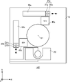
- FIG. 5A shows a modified example of the input device 100.
- the input device 100 of this example differs from the embodiment of FIG. 3A in that it includes two sensors 40a and a sensor 40b.
- the input device 100 of this example detects the movement of two magnets 20 moving in the X-axis direction or the Y-axis direction by two sensors 40.
- the sensor 40a is provided on the positive side of the magnet moving portion 30a in the X-axis direction, and detects a change in the magnetic field according to the position of the magnet 20a.
- the sensor 40a may be a single-axis sensor for detecting a change in the magnetic field according to the position of the magnet 20a, or may be a multi-axis sensor.
- the sensor 40a is an example of a first sensor for detecting the magnetic field of the magnet 20a.
- the sensor 40b is provided on the negative side of the magnet moving portion 30b in the Y-axis direction, and detects a change in the magnetic field according to the position of the magnet 20b.
- the sensor 40b may be a single-axis sensor for detecting a change in the magnetic field according to the position of the magnet 20b, or may be a multi-axis sensor.
- the sensor 40b is an example of a second sensor for detecting the magnetic field of the magnet 20b.
- the sensor 40a and the sensor 40b of this example are provided in a region different from the region in which the magnet 20a or the magnet 20b moves in the top view. Further, the sensor 40a and the sensor 40b are provided at positions asymmetrical with respect to the center C1 of the operation unit 15 in the top view. That is, the sensor 40a and the sensor 40b are not provided below the center C1 of the operation unit 15. As a result, the input device 100 can be made thinner.
- the plurality of magnets 20 of this example are provided at positions separated from each other in the top view. Therefore, the input device 100 of this example can reduce the influence of the attractive force and the repulsive force between the magnets 20 and suppress the influence of the operation unit 15 on the operation feeling.
- FIG. 5B shows a modified example of the input device 100.
- the positions of the two sensors 40a and the sensor 40b are different from those of the embodiment of FIG. 5A.
- the sensor 40a is arranged on the side of the moving magnet 20a.
- the sensor 40a of this example is arranged on the negative side in the Y-axis direction with respect to the magnet 20a when the magnet 20a moves in the X-axis direction. That is, the sensor 40a is arranged on the negative side in the Y-axis direction with respect to the magnet moving portion 30a.
- the sensor 40b is arranged on the side of the moving magnet 20b.
- the sensor 40b of this example is arranged on the positive side in the X-axis direction with respect to the magnet 20b when the magnet 20b moves in the Y-axis direction. That is, the sensor 40b is arranged on the positive side in the X-axis direction with respect to the magnet moving portion 30b.
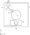
- FIG. 5C shows a modified example of the input device 100.
- the input device 100 of this example includes one sensor 40 and one magnet 20 provided on the outer periphery of the sensor 40.
- the input device 100 of this example detects the movement of one magnet 20 moving in the XY plane with one sensor 40.
- the sensor 40 of this example is provided in a region different from the region where the magnet 20 moves in the top view.
- the sensor 40 is provided in the vicinity of the operation unit 15 in the top view, but is not limited thereto.
- the sensor 40 of this example is provided in the vicinity of a predetermined circle C2 in which the magnet 20 is arranged in the top view.
- the magnet 20 is provided in a predetermined circle C2 in the top view.
- the magnet 20 of this example moves on the outer circumference and the inside of the circle C2 according to the tilting operation of the operation unit 15. However, the magnet 20 may deviate from the circle C2 and move in any region in the XY plane.
- the magnet moving portion 30 of this example is not shown.
- the input device 100 of this example is provided with one magnet 20 and one sensor 40, so that the movement of the operation unit 15 can be detected.
- FIG. 5D shows a modified example of the input device 100.
- the input device 100 of this example includes two sensors 40a and a sensor 40b, and one magnet 20.
- the input device 100 of this example detects the movement of one magnet 20 moving in the XY plane by two sensors 40a and the sensor 40b.
- the magnet 20 is arranged so as to move within a predetermined circle C2 in a top view.
- the magnet 20 of this example moves on the outer circumference and the inside of the circle C2 according to the tilting operation of the operation unit 15.
- the magnet 20 of this example includes a first pole 21 and a second pole 22 arranged in a predetermined direction in the XY plane.
- the sensor 40a and the sensor 40b are arranged outside the circle C2 in which the magnet 20 moves in the top view.
- the sensor 40a of this example is provided on the positive side of the circle C2 in which the magnet 20 moves in the X-axis direction
- the sensor 40b is provided on the negative side of the circle C2 in which the magnet 20 moves in the Y-axis direction.
- the positions of the sensor 40a and the sensor 40b are not limited to this example as long as the magnetic field of the magnet 20 can be detected.
- the input device 100 can arbitrarily determine the number and position of the magnet 20 and the sensor 40, the degree of freedom in layout is high and it is easy to realize miniaturization.
- the degree of freedom in layout is high and it is easy to realize miniaturization.
- simple wiring can be realized and workability at the time of mounting can be improved.
- the mounting error can be reduced.
- FIG. 6A is a cross-sectional view showing a modified example of the input device 100.
- the heights of the magnet 20 and the sensor 40 are adjusted so as to overlap each other.
- the sensor 40 is arranged at the same height as the magnet 20 in the Z-axis direction.
- the same height may mean that at least one part of the magnet 20 and the sensor 40 overlap in the Z-axis direction.
- the heights of the magnet 20 and the sensor 40 of this example are adjusted so that the centers in the Z-axis direction coincide with each other. By aligning the heights of the magnet 20 and the sensor 40 in the Z-axis direction, the magnetic field input in the Z-axis direction of the sensor 40 is less likely to change even if the magnet 20 moves. As a result, the input device 100 can improve the accuracy of disturbance detection by detecting the magnetic field in the Z-axis direction.
- FIG. 6B is a cross-sectional view showing a modified example of the input device 100.
- the magnetic field generation unit 60 is arranged above the sensor 40.
- the magnetic field generating unit 60 has a first pole 61 and a second pole 62, and generates a magnetic field having a predetermined size.
- the first pole 61 is the S pole and the second pole 62 is the N pole.
- the magnetic field generating unit 60 of this example is fixed above the housing 10, and applies a magnetic field of a predetermined strength to the sensor 40.
- the shape of the magnetic field generating portion 60 of this example is a rectangular parallelepiped, but the shape is not limited to this.
- the first pole 61 is arranged at a position close to the sensor 40, and the second pole 62 is arranged at a position away from the sensor 40, but the first pole 61 and the second pole 62 are conversely the same. It may be arranged. That is, the magnetic field generating unit 60 only needs to be able to apply a magnetic field to the sensor 40 in the Z-axis direction, and its magnetizing direction is not limited.
- FIG. 6C is a top view showing a modified example of the input device 100.
- the magnetic field generating unit 60 is arranged directly above the sensor 40, but it does not necessarily have to be arranged directly above the sensor 40.
- the position of the magnetic field generating unit 60 may be above the sensor 40 and may be a position partially overlapping the sensor 40 in the top view.
- the position of the magnetic field generator 60 depends, for example, on the placement position of other components of the input device 100, or on the strength of the magnetic field desired to be applied in the X and Y axis directions of the sensor 40, or the measurement range of the sensor 40. Depending on the situation, they may be arranged so as to be offset in the X, Y and Z axis directions. Since the magnetic field generating portion 60 is a fixed magnet, a magnet moving portion is unnecessary and there is no limitation on the thinness. Therefore, it can be added within a range that does not affect the thinning of the housing 10.
- the input device 100 of this example can correct the magnetic field data when the temperature changes by applying a magnetic field to the sensor 40 in the Z-axis direction using the magnetic field generating unit 60.
- B x and B z can be expressed by the following equation 1. ..
- B x (20) and B x (60) are the magnitudes of the magnetic fields in the X-axis direction given to the sensor 40 by the magnet 20 and the magnetic field generating unit 60, respectively
- B z (60) is the magnitude of the magnetic field in the X-axis direction. It is the magnitude of the magnetic field in the Z-axis direction applied to the sensor 40.
- the magnet 20 and the sensor 40 are at the same height in the Z-axis direction, the magnet 20 does not apply a magnetic field in the Z-axis direction to the sensor 40.
- the following equation 2 is obtained.
- Equation 2 When the temperature changes by ⁇ T, the magnitude of the magnetic field changes linearly with the temperature, so that Equation 2 is transformed as in Equation 3 below.
- ⁇ 20 and ⁇ 20 are coefficients determined by the magnet material of the magnet 20
- ⁇ 60 and ⁇ 60 coefficients determined by the magnet material of the magnetic field generating unit 60.
- Equation 4 does not include ⁇ T, it can be seen that the displacement of the position coordinates due to the temperature characteristics of the magnet 20 can be prevented by applying the magnetic field in the Z-axis direction using the magnetic field generating unit 60.
- the magnetic field data output by the sensor 40 can be corrected by the above calculation with reference to the magnetic field applied to the sensor 40 by the magnetic field generating unit 60 having the same temperature characteristics. As a result, it is possible to prevent the position coordinates of the detected operation unit 15 from being displaced due to the temperature characteristics of the magnet 20.
- the magnet 20 and the sensor 40 in the Z-axis direction are the same has been described, but the magnet 20 may have a height different from that of the sensor 40 in the Z-axis direction.
- the magnitude of the magnetic field applied to the sensor 40 by the magnetic field generating unit 60 may be larger than the magnitude of the magnetic field applied to the sensor 40 by the magnet 20. That is, when the magnitude of the magnetic field applied to the sensor 40 by the magnet 20 in the Z-axis direction is B z (20), B z (60) may be larger than B z (20).
- the distance between the magnetic field generating unit 60 and the sensor 40 may be smaller than the distance when the magnet 20 and the sensor 40 are in close contact with each other.
- the magnitude of the magnetic field applied to the sensor 40 by the magnetic field generating unit 60 can be made larger than the magnitude of the magnetic field applied to the sensor 40 by the magnet 20. More specifically, as will be described later, in one example, the minimum distance from the intersection P1 to the magnet 20 is 2.5 mm, so that the distance from the upper surface of the sensor 40 to the bottom surface of the magnetic field generating portion 60 is less than 2.5 mm. Therefore, B z (60) can be made larger than B z (20).
- Equation 2 the variable on the right side is only B x (20), whereas in Equation 5, a variable called B z (20) is added, which complicates the calculation. Therefore, for example, by adjusting the arrangement of the magnetic field generating unit 60 and the magnet 20 to make B z (60) larger than B z (20), the above equation 5 is approximated as the following equation 6. As a result, it becomes possible to handle as in the above equation 4.
- FIG. 6D shows an example of a disturbance detection method by the input device 100.
- the input device 100 of this example sets a predetermined threshold value B1 and a threshold value B2 of the magnetic flux density (mT), and when the detected magnetic field in the Z-axis direction exceeds the range from the threshold value B1 to the threshold value B2. Judge that a disturbance has been detected.
- the input device 100 can easily suppress the influence of the movement of the magnet 20 on the magnetic flux density in the Z-axis direction. This makes it possible to improve the accuracy of disturbance detection.
- the threshold value B1 may be a value obtained by subtracting a magnetic field equivalent to the geomagnetism from the minimum value of the magnetic field applied to the sensor 40 when the operation unit 15 is operated in a predetermined pattern.
- the threshold value B2 may be a value obtained by adding a magnetic field equivalent to the geomagnetism to the maximum value of the magnetic field applied to the sensor 40 when the operation unit 15 is operated in a predetermined pattern.
- the value subtracted from the maximum value and the minimum value may be a value having a margin larger than the magnetic flux density due to the geomagnetism. This makes it possible to suppress the influence of the magnetic field generated by the metal component (for example, a spring) magnetized by the magnet 20. In addition, the influence of the magnetic field generated by the movement of the magnet 20 due to the mounting error can be suppressed.
- the threshold B1 and the threshold B2 are ⁇ 500 ⁇ T and +500 ⁇ T, respectively.
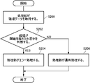
- FIG. 6E shows an example of a flowchart of the threshold setting method.
- the flowchart of this example is an example of the process for setting the threshold value for detecting the disturbance in the normal process state.
- step S100 acquisition of magnetic field data is started.
- the acquisition of the magnetic field data may be executed by a processing unit provided inside the input device 100, or may be executed by a processing unit provided outside the input device 100.
- step S102 the operation unit 15 is operated in a predetermined pattern.
- the operation is performed so as to go around the outer circumference of the operation unit 15.
- the user may operate the operation unit 15 in a predetermined pattern by displaying a guidance such as "Please tilt the stick straight up and slowly turn it clockwise over 5 seconds.”
- the threshold value is set based on the magnetic field data acquired in step S102.
- the maximum value and the minimum value may be extracted from the magnetic field data acquired in step S102.
- the threshold is set based on the maximum and minimum values of the magnetic field data acquired in step S102 and the geomagnetism. For example, the value obtained by subtracting the magnetic field corresponding to the geomagnetism from the minimum value of the magnetic field data acquired in step S102 is set to the threshold value B1, and the value obtained by adding the magnetic field equivalent to the geomagnetism to the maximum value is set to the threshold value B2. This makes it possible to avoid erroneous detection of disturbance due to the movement of the magnet 20 during normal operation.
- the threshold setting method of this example may be executed at the time of manufacturing the input device 100, may be executed after the input device 100 is mounted on the controller, or may be executed by a user who uses the input device 100. You may. For example, the user may reset the threshold value after setting the threshold value at the time of factory shipment of the input device 100.
- FIG. 6F shows an example of an operation flowchart for processing magnetic field data.
- the processing unit acquires the magnetic field data.
- the magnetic field data in the normal processing state may be acquired.
- the normal processing state refers to a state in which a game is being played using the input device 100, for example, when the input device 100 is a controller for a game.
- the threshold value set in step S104 may be used. If the magnetic field exceeds the threshold value, error processing is executed in step S204, and if the magnetic field does not exceed the threshold value, normal processing is continued in step S206.
- the error processing may be a processing that does not adopt the magnetic field data that exceeds the threshold value, or may be a processing that notifies the user that a disturbance has been detected. In this way, by detecting the disturbance using the 3-axis magnetic sensor for the sensor 40, it is possible to realize the error processing of the disturbance.
- FIG. 7A is an operation flowchart of the system for confirming the normal operation of the sensor 40.
- the processing unit starts communication with the sensor 40.
- the processing unit acquires the magnetic field data from the sensor 40. If the communication is not normal, report an operation error. The specific method for determining the magnetic field data in step S320 will be described later.
- step S330 it is determined whether or not the magnetic field data is normal, the confirmation is completed when the magnetic field data is normal, and when the magnetic field data is not normal, an operation abnormality is reported.
- the input device 100 can confirm that the magnet 20 and the sensor 40 are correctly arranged and that the sensor 40 is operating normally.
- the determination of whether or not the communication in step S310 is normal may be executed by an authentication operation between the processing unit and the input device 100.
- the processing unit designates the sensor 40 by the slave address and determines the read value of a specific register (device ID). After determining the read value of the device ID, the processing unit may execute a self-diagnosis function (that is, a self-test) and determine whether or not communication is normal based on the result.
- a self-diagnosis function that is, a self-test
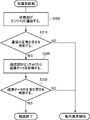
- FIG. 7B shows an example of an operation flowchart for acquiring magnetic field data.
- the operation flowchart of this example shows a specific method for determining whether or not the magnetic field data is normal in step S320.
- step S322 the operation unit 15 is operated in a predetermined pattern.
- the processing unit may instruct the user to operate in a predetermined pattern.
- step S324 it is determined whether or not there is an abnormality in the direction of the magnet 20. If there is an abnormality in the orientation of the magnet 20, it is determined that there is an abnormality in the magnetic field data, and if there is no abnormality in the orientation of the magnet 20, it is determined in step S326 whether there is an abnormality in the strength of the magnet 20. If there is an abnormality in the strength of the magnet 20, it is determined that there is an abnormality in the magnetic field data, and if there is no abnormality in the strength of the magnet 20, it is determined in step S328 whether or not the mounting error of the input device 100 is within the allowable range.
- each step is determined using at least one of the magnitude of the magnetic field output, the polarity of the magnetic field output, or the distortion of the magnetic field output obtained by the operation of step S322.
- the order in which steps S324 to S328 are executed may be changed as appropriate. After step S322, at least one of steps S324 to S328 may be executed.
- FIG. 8 is an example of the input device 100 when the magnet 20 is arranged in a repulsive force.
- the input device 100 of this example has the same basic configuration as the embodiment of FIG. 3A.
- the polarities of the input device 100 are arranged so that when the magnet 20a and the magnet 20b approach the sensor 40, they repel each other. In this way, in the case of the repulsive force arrangement in which the magnets 20a and the magnets 20b repel each other, the repulsive force between the two magnets acts in the direction of returning the operating portion 15 to the reference position. Since the return force to the reference position by the spring is applied in the direction of returning the operation unit 15 to the reference position, it is difficult for the user to feel the repulsive force between the magnets 20.
- the attractive force arrangement in which the magnets 20 attract each other, the attractive force acts in the direction of canceling the return force to the reference position by the spring, so that the user can return the operation unit 15 only when the operation unit 15 is tilted in a specific direction. You may get the impression that it is bad. Therefore, by arranging the magnets 20 to repel each other, the operability of the input device 100 can be easily improved.
- the magnet 20 in the case of the attractive force arrangement, it is necessary to attach the magnet 20 to the magnet moving portion 30 in the opposite directions, whereas in the case of the repulsive force arrangement, the magnet 20 may be attached to the magnet moving portion 30 in the same direction. .. Therefore, in the repulsive force arrangement, the same member can be reused for the magnet moving portion 30a and the magnet moving portion 30b, so that mass productivity can be improved.
- FIG. 9A shows an example of an enlarged view in the vicinity of the sensor 40.
- an example of the layout design method of the input device 100 is shown.
- the distance L is the distance between the intersection P1 and the center C1 in the X-axis direction or the Y-axis direction.
- the distance La indicates the distance between the intersection P1 and the center C1 in the X-axis direction.
- the distance Lb indicates the distance between the intersection P1 and the center C1 in the Y-axis direction.
- the magnet moving unit 30 may move the magnet 20 within the range of the distance L.
- the distance L is 5 mm or more and 8 mm or less.
- the distance La in this example is the same as the distance Lb, but may be different.
- the width W is the width of the magnet 20 in the direction in which the magnet 20 moves. That is, the width W corresponds to one side of the magnet 20.
- the width Wa indicates the width of the magnet 20a in the X-axis direction.
- the width Wb indicates the width of the magnet 20b in the Y-axis direction.
- the magnet 20 may have sides having a length of 10% or more and 50% or less of the distance L. In one example, the magnet 20 has sides of 1 mm or more and 5 mm or less.
- the width W1 of this example is 2 mm.
- the width Wa of this example is the same as the width Wb, but may be different.
- the volume of the magnet 20 is, for example, 8 mm 3 .
- the Distance D indicates the distance between the intersection P1 and the magnet 20.
- the distance D changes depending on the position of the magnet 20.
- the distance Dmin is the minimum distance of the distance D
- the distance Dmax is the maximum distance of the distance D. In one example, the distance Dmin is 2.5 mm and the distance Dmax is 4.5 mm.
- the minimum length that can be perceived as a human moving a finger is about 0.1 mm.
- the input device 100 tries to detect 0.1 mm, it is necessary to divide the stroke S1 of about 6 mm of the operation unit 15 into about 60. That is, it is necessary to divide the stroke S1 of the magnet 20 interlocking with the operation unit 15 into about 60.
- the stroke S1 will be described later.
- the magnitude of the geomagnetism is 30 ⁇ T to 60 ⁇ T, and it is necessary to prevent this from affecting the normal operation as much as possible.
- the distance D satisfying such a condition is set to 2.5 mm or more and 4.5 mm or less. This makes it possible to suppress the influence of the geomagnetism during use.
- FIG. 9B shows a cross-sectional view of the input device 100.
- the width W1 indicates the width of the housing 10 in the X-axis direction.
- the width W1 is, for example, 15 mm or more and 25 mm or less.
- the height H indicates the height of the input device 100 from the bottom surface of the housing 10 to the top surface of the operation unit 15.
- the height H is, for example, 12 mm or more and 16 mm or less.
- the stroke S1 is the maximum distance that the operation unit 15 moves due to the inclination of the operation unit 15.
- the stroke S1 of this example is the apex of the operation unit 15 when the operation unit 15 is moved from the position when the operation unit 15 is most inclined to the positive side in the X-axis direction to the position when the operation unit 15 is most inclined to the negative side in the X-axis direction.
- the operation unit 15 may have the same stroke S1 in any direction of the XY plane.
- FIG. 10 shows an example of the input device 500 according to the comparative example.
- the input device 500 slides the drive unit 510 connected to the operation unit 515 to move the contact portion 525 of the metal electrode in contact with the sheet resistance portion 520.
- a sheet resistance unit 520 is arranged at one end of the drive unit 510, and an electrode 530 is arranged at the other end.
- the input device 500 outputs an output voltage according to the inclination of the operation unit 515.
- the contact between the sheet resistance portion 520 and the contact portion 525 may cause the surface 522 of the sheet resistance portion 520 to wear and the output of the input device 500 to become unstable. If the output of the input device 500 becomes unstable, the controller equipped with the input device 500 may malfunction.
- FIG. 11 shows an example of the configuration of the controller 200.
- the controller 200 of this example includes two input devices 100a and an input device 100b.
- the number of input devices 100 is not limited to this.
- the user can operate the operation unit 15a and the operation unit 15b with their thumbs to play a video game.
Landscapes
- Engineering & Computer Science (AREA)
- Multimedia (AREA)
- Human Computer Interaction (AREA)
- General Engineering & Computer Science (AREA)
- Physics & Mathematics (AREA)
- General Physics & Mathematics (AREA)
- Theoretical Computer Science (AREA)
- Automation & Control Theory (AREA)
- Position Input By Displaying (AREA)
Abstract
Description
特許文献1 特開2012-221342号公報
特許文献2 特開2013-065398号公報
特許文献3 特開2016-207634号公報 Conventionally, an input device for inputting a signal corresponding to an operation of an operation unit is known (see, for example, Patent Document 1).


Claims (20)
- 磁場を発生する磁石と、
前記磁石が発生した磁場を検出するためのセンサと、
予め定められた第1平面において、前記磁石の位置を移動させるための磁石移動部と
を備え、
前記磁石は、第1磁石および第2磁石を含み、
前記センサは、前記第1平面に対する上面視において、前記磁石が移動する領域と異なる領域に設けられ、
前記磁石移動部は、前記第1平面において、予め定められた第1方向に前記第1磁石を移動させ、前記第1平面において、前記第1方向と異なる第2方向に前記第2磁石を移動させるように構成され、
前記第1方向および前記第2方向は、前記第1平面において直交し、
前記センサは、前記第1磁石および前記第2磁石に共通に設けられる
入力装置。 A magnet that generates a magnetic field and
A sensor for detecting the magnetic field generated by the magnet, and
A magnet moving portion for moving the position of the magnet on a predetermined first plane is provided.
The magnet includes a first magnet and a second magnet.
The sensor is provided in a region different from the region in which the magnet moves in a top view with respect to the first plane.
The magnet moving portion moves the first magnet in a predetermined first direction in the first plane, and moves the second magnet in a second direction different from the first direction in the first plane. Configured to let
The first direction and the second direction are orthogonal to each other in the first plane.
The sensor is an input device commonly provided for the first magnet and the second magnet. - 前記センサは、上面視において、前記第1方向と前記第2方向との交点に設けられる
請求項1に記載の入力装置。 The input device according to claim 1, wherein the sensor is provided at an intersection of the first direction and the second direction in a top view. - 前記第1磁石の前記センサ側に配置された極性は、前記第2磁石の前記センサ側に配置された極性と同一である
請求項2に記載の入力装置。 The input device according to claim 2, wherein the polarity arranged on the sensor side of the first magnet is the same as the polarity arranged on the sensor side of the second magnet. - 前記センサは、
前記第1磁石の磁場を検出するための第1センサと、
前記第2磁石の磁場を検出するための第2センサと
を含む請求項1に記載の入力装置。 The sensor is
The first sensor for detecting the magnetic field of the first magnet and
The input device according to claim 1, further comprising a second sensor for detecting the magnetic field of the second magnet. - 前記磁石は、第1極および第2極を含み、
前記第1極および前記第2極は、前記第1平面内の予め定められた方向に配列される
請求項1から3のいずれか一項に記載の入力装置。 The magnet includes a first pole and a second pole.
The input device according to any one of claims 1 to 3, wherein the first pole and the second pole are arranged in a predetermined direction in the first plane. - 前記磁石移動部によって前記磁石を操作するための操作部を備え、
前記磁石移動部は、前記操作部による操作と連動して前記磁石を移動させる
請求項1から5のいずれか一項に記載の入力装置。 An operation unit for operating the magnet by the magnet moving unit is provided.
The input device according to any one of claims 1 to 5, wherein the magnet moving unit moves the magnet in conjunction with an operation by the operation unit. - 前記磁石移動部は、前記第1磁石が移動する第1方向と前記第2磁石が移動する第2方向との交点と、操作部の上面視における中心との間の距離Lの範囲内で前記磁石を移動させる
請求項1から4のいずれか一項に記載の入力装置。 The magnet moving portion is said to be within a distance L between the intersection of the first direction in which the first magnet moves and the second direction in which the second magnet moves and the center in the top view of the operating portion. The input device according to any one of claims 1 to 4, wherein the magnet is moved. - 前記磁石が移動する方向における前記磁石の幅は、前記距離Lの10%以上、50%以下の長さである
請求項7に記載の入力装置。 The input device according to claim 7, wherein the width of the magnet in the direction in which the magnet moves is a length of 10% or more and 50% or less of the distance L. - 前記磁石が移動する方向における前記磁石の幅は、1mm以上、5mm以下である
請求項1から8のいずれか一項に記載の入力装置。 The input device according to any one of claims 1 to 8, wherein the width of the magnet in the direction in which the magnet moves is 1 mm or more and 5 mm or less. - 前記センサは、上面視において、操作部の中心に対してずれた位置に設けられる
請求項6から9のいずれか一項に記載の入力装置。 The input device according to any one of claims 6 to 9, wherein the sensor is provided at a position deviated from the center of the operation unit in a top view. - 前記センサは、3軸の磁場を検出可能な3軸磁気センサである
請求項1から9のいずれか一項に記載の入力装置。 The input device according to any one of claims 1 to 9, wherein the sensor is a 3-axis magnetic sensor capable of detecting a 3-axis magnetic field. - 前記センサは、前記第1平面と直交する高さ方向において、前記磁石と同一の高さに配置される
請求項1から11のいずれか一項に記載の入力装置。 The input device according to any one of claims 1 to 11, wherein the sensor is arranged at the same height as the magnet in a height direction orthogonal to the first plane. - 前記センサは、前記第1平面と直交する高さ方向において、前記磁石と少なくとも一部が重複する
請求項1から12のいずれか一項に記載の入力装置。 The input device according to any one of claims 1 to 12, wherein the sensor is at least partially overlapped with the magnet in a height direction orthogonal to the first plane. - 前記磁石および前記センサは、前記第1平面と直交する高さ方向において、中心が一致する
請求項1から13のいずれか一項に記載の入力装置。 The input device according to any one of claims 1 to 13, wherein the magnet and the sensor have centers aligned in a height direction orthogonal to the first plane. - 前記第1平面に対する側面視において、前記センサの上方に設けられた磁場発生部を更に備える
請求項1から14のいずれか一項に記載の入力装置。 The input device according to any one of claims 1 to 14, further comprising a magnetic field generating unit provided above the sensor in a side view with respect to the first plane. - 前記磁場発生部の材料は、前記磁石の材料と同一である
請求項15に記載の入力装置。 The input device according to claim 15, wherein the material of the magnetic field generating portion is the same as the material of the magnet. - 前記磁場発生部が前記センサに印加する磁場は、前記磁石が前記センサに印加する磁場より大きい
請求項15または16に記載の入力装置。 The input device according to claim 15 or 16, wherein the magnetic field applied to the sensor by the magnetic field generating unit is larger than the magnetic field applied to the sensor by the magnet. - 前記磁場発生部と前記センサとの間の距離は、前記磁石と前記センサとが最近接した場合の距離より小さい
請求項15から17のいずれか一項に記載の入力装置。 The input device according to any one of claims 15 to 17, wherein the distance between the magnetic field generating unit and the sensor is smaller than the distance when the magnet and the sensor are in close contact with each other. - 請求項1から18のいずれか一項に記載の入力装置を備えた
コントローラ。 A controller including the input device according to any one of claims 1 to 18. - 操作部の操作に応じて移動する磁石と、前記磁石が発生した磁場を検出するためのセンサとを備える入力装置のエラー検知方法であって、
前記操作部を予め定められたパターンで操作する段階と、
前記予め定められたパターンに基づいて磁場データを取得する段階と、
前記取得した磁場データに基づいて、前記磁石の向きの異常、前記磁石の強度の異常、または前記入力装置の実装誤差が許容範囲であるか否かの少なくとも1つを判定する段階とを備える
エラー検知方法。 It is an error detection method of an input device including a magnet that moves according to the operation of the operation unit and a sensor for detecting the magnetic field generated by the magnet.
The stage of operating the operation unit in a predetermined pattern and
The stage of acquiring magnetic field data based on the predetermined pattern, and
An error including a step of determining at least one of an abnormality in the orientation of the magnet, an abnormality in the strength of the magnet, and whether or not the mounting error of the input device is within an allowable range based on the acquired magnetic field data. Detection method.
Priority Applications (3)
| Application Number | Priority Date | Filing Date | Title |
|---|---|---|---|
| CN202180083949.0A CN116583810A (en) | 2020-12-14 | 2021-12-07 | Input device, controller, and error detection method |
| JP2022569897A JP7518202B2 (en) | 2020-12-14 | 2021-12-07 | Input device, controller and error detection method |
| US18/333,511 US20230321526A1 (en) | 2020-12-14 | 2023-06-12 | Input device, controller, and error detection method |
Applications Claiming Priority (2)
| Application Number | Priority Date | Filing Date | Title |
|---|---|---|---|
| JP2020-207047 | 2020-12-14 | ||
| JP2020207047 | 2020-12-14 |
Related Child Applications (1)
| Application Number | Title | Priority Date | Filing Date |
|---|---|---|---|
| US18/333,511 Continuation US20230321526A1 (en) | 2020-12-14 | 2023-06-12 | Input device, controller, and error detection method |
Publications (1)
| Publication Number | Publication Date |
|---|---|
| WO2022131078A1 true WO2022131078A1 (en) | 2022-06-23 |
Family
ID=82057724
Family Applications (1)
| Application Number | Title | Priority Date | Filing Date |
|---|---|---|---|
| PCT/JP2021/044961 WO2022131078A1 (en) | 2020-12-14 | 2021-12-07 | Input device, controller, and error detection method |
Country Status (4)
| Country | Link |
|---|---|
| US (1) | US20230321526A1 (en) |
| JP (1) | JP7518202B2 (en) |
| CN (1) | CN116583810A (en) |
| WO (1) | WO2022131078A1 (en) |
Citations (5)
| Publication number | Priority date | Publication date | Assignee | Title |
|---|---|---|---|---|
| US4459578A (en) * | 1983-01-13 | 1984-07-10 | Atari, Inc. | Finger control joystick utilizing Hall effect |
| JPH11249807A (en) * | 1998-03-05 | 1999-09-17 | Sensor Tec Kk | Stick controller |
| JP2000003651A (en) * | 1998-06-12 | 2000-01-07 | Yazaki Corp | Switch |
| JP2020091538A (en) * | 2018-12-03 | 2020-06-11 | 日立オートモティブシステムズ株式会社 | Vehicle pedal stroke detection device and vehicle control unit |
| JP2020153664A (en) * | 2019-03-18 | 2020-09-24 | Tdk株式会社 | Signal processing circuit, position detector, and magnetic sensor system |
-
2021
- 2021-12-07 CN CN202180083949.0A patent/CN116583810A/en active Pending
- 2021-12-07 WO PCT/JP2021/044961 patent/WO2022131078A1/en active Application Filing
- 2021-12-07 JP JP2022569897A patent/JP7518202B2/en active Active
-
2023
- 2023-06-12 US US18/333,511 patent/US20230321526A1/en active Pending
Patent Citations (5)
| Publication number | Priority date | Publication date | Assignee | Title |
|---|---|---|---|---|
| US4459578A (en) * | 1983-01-13 | 1984-07-10 | Atari, Inc. | Finger control joystick utilizing Hall effect |
| JPH11249807A (en) * | 1998-03-05 | 1999-09-17 | Sensor Tec Kk | Stick controller |
| JP2000003651A (en) * | 1998-06-12 | 2000-01-07 | Yazaki Corp | Switch |
| JP2020091538A (en) * | 2018-12-03 | 2020-06-11 | 日立オートモティブシステムズ株式会社 | Vehicle pedal stroke detection device and vehicle control unit |
| JP2020153664A (en) * | 2019-03-18 | 2020-09-24 | Tdk株式会社 | Signal processing circuit, position detector, and magnetic sensor system |
Also Published As
| Publication number | Publication date |
|---|---|
| JP7518202B2 (en) | 2024-07-17 |
| US20230321526A1 (en) | 2023-10-12 |
| CN116583810A (en) | 2023-08-11 |
| JPWO2022131078A1 (en) | 2022-06-23 |
Similar Documents
| Publication | Publication Date | Title |
|---|---|---|
| EP1380927A1 (en) | Pointing device | |
| JP7107330B2 (en) | Magnetic sensor and manufacturing method thereof | |
| KR20120007970A (en) | Input apparatus | |
| JP7524785B2 (en) | Operating device | |
| CN112672861B (en) | Manipulator, manipulator control method, and program | |
| WO2020066063A1 (en) | End effector device | |
| TW202138944A (en) | Trajectory control device | |
| JP2015071207A (en) | Robot hand and control method thereof | |
| CN111707296A (en) | Position detection device, signal processing circuit, and magnetic sensor system | |
| WO2022131078A1 (en) | Input device, controller, and error detection method | |
| WO2020066066A1 (en) | End effecter device | |
| JP6372054B2 (en) | LOCK MECHANISM AND OPTICAL DEVICE HAVING THE SAME | |
| US8218956B2 (en) | Driving system and hand tremor compensating apparatus adopting the same | |
| JP6988757B2 (en) | End effector and end effector device | |
| JP2013156292A (en) | Lens drive device | |
| JPH06226671A (en) | Robot hand control device | |
| JP6147884B2 (en) | Lens drive device | |
| CN114791578A (en) | Magnetic sensor | |
| JPH04348885A (en) | Method for detecting fitting position in assembly of parts by use of robot | |
| JP6925544B2 (en) | Contact state recognition device and robot system | |
| EP2086113A2 (en) | Swing type switching device including magnet and magnetoresistive element | |
| WO2023008312A1 (en) | Shift device | |
| KR100852161B1 (en) | Pointing device and electronic device having the same | |
| WO2023008311A1 (en) | Shift device | |
| WO2020202778A1 (en) | Lens drive device |
Legal Events
| Date | Code | Title | Description |
|---|---|---|---|
| 121 | Ep: the epo has been informed by wipo that ep was designated in this application |
Ref document number: 21906441 Country of ref document: EP Kind code of ref document: A1 |
|
| ENP | Entry into the national phase |
Ref document number: 2022569897 Country of ref document: JP Kind code of ref document: A |
|
| WWE | Wipo information: entry into national phase |
Ref document number: 202180083949.0 Country of ref document: CN |
|
| NENP | Non-entry into the national phase |
Ref country code: DE |
|
| 122 | Ep: pct application non-entry in european phase |
Ref document number: 21906441 Country of ref document: EP Kind code of ref document: A1 |