WO2022130646A1 - ポンプの運転方法およびポンプを備えた装置 - Google Patents
ポンプの運転方法およびポンプを備えた装置 Download PDFInfo
- Publication number
- WO2022130646A1 WO2022130646A1 PCT/JP2020/047559 JP2020047559W WO2022130646A1 WO 2022130646 A1 WO2022130646 A1 WO 2022130646A1 JP 2020047559 W JP2020047559 W JP 2020047559W WO 2022130646 A1 WO2022130646 A1 WO 2022130646A1
- Authority
- WO
- WIPO (PCT)
- Prior art keywords
- pump
- pressure
- mpa
- discharge pressure
- water
- Prior art date
- Legal status (The legal status is an assumption and is not a legal conclusion. Google has not performed a legal analysis and makes no representation as to the accuracy of the status listed.)
- Ceased
Links
Images

Classifications
-
- F—MECHANICAL ENGINEERING; LIGHTING; HEATING; WEAPONS; BLASTING
- F04—POSITIVE - DISPLACEMENT MACHINES FOR LIQUIDS; PUMPS FOR LIQUIDS OR ELASTIC FLUIDS
- F04B—POSITIVE-DISPLACEMENT MACHINES FOR LIQUIDS; PUMPS
- F04B49/00—Control, e.g. of pump delivery, or pump pressure of, or safety measures for, machines, pumps, or pumping installations, not otherwise provided for, or of interest apart from, groups F04B1/00 - F04B47/00
- F04B49/08—Regulating by delivery pressure
Definitions
- the present invention relates to an operation method of a pump preferably used for a subdivision treatment of a molten metal, and an apparatus using the operation method.
- Micrometer-order metal particles which are widely used for electronic components, are produced by a wet reduction method or an atomizing method.
- metal particles produced by the wet reduction method since the particles are formed by using a chemical reaction, there is a problem that the impurity components such as the chemicals used cannot be completely removed from the metal particles, and the metal particles have high conductivity. Is not always welcomed in applications that require.
- the water atomization method is used for the production of alloy powder and the water atomization method is used for the production of iron-based powder. ..
- fine particles are oriented toward the miniaturization of electronic components.
- a method of injecting a spray medium having a high pressure and a large flow rate is adopted.
- the water atomizing method can keep the manufacturing cost relatively low, the cooling efficiency of the particles is high, and the shape tends to be indefinite, whereas the gas atomizing method uses argon or the like. Since the use of an inert gas such as nitrogen increases the manufacturing cost, it has the characteristic that spherical particles can be easily obtained.
- Patent Document 1 a subcritical water having a pressure of 0.5 to 22 MPa and a water temperature of 150 to 374 ° C., which is pressurized to a molten metal falling in the vertical direction, is jetted and collided with each other to cause amorphous.
- a method for producing a soft magnetic metal powder having a conversion rate of 90% or more is disclosed.
- Patent Document 2 discloses an example in which the applicant has pulverized molten metal particles at a water pressure of 115 MPa.
- Patent Documents 1 and 2 relate to the water atomizing method among the atomizing methods, and in the case of Patent Document 1, the pressurizing pressure of the sprayed water is 0.5 to 22 MPa. It is stated that the particle size of the obtained iron alloy particles is about 30 to 40 ⁇ m. In addition, the applicant performed water atomization on copper using a water pressure of 115 MPa, and found that the D50 particle size of the obtained particles was about 3.5 ⁇ m.
- Patent Document 2 proposes that the spray pressure is 115 MPa or more as a method for obtaining fine metal particles.
- the spray pressure is 115 MPa or more as a method for obtaining fine metal particles.
- a large load is applied to various members by the water discharged from the pump, so that the deterioration of these peripheral members is remarkable and running. It has been found that it can lead to a significant increase in cost.
- the pipe through which a high-pressure fluid flows is long, the pipe tends to rupture, and once the pipe ruptures, production must be stopped, which causes a problem that productivity is significantly deteriorated. .. If these problems are not solved, it may be extremely difficult to industrially produce fine particles by the water atomization method.
- the present invention has been made in order to meet the above-mentioned requirements, and is a method for operating a pump, which has a small load on peripheral members and can reduce running costs in the supply of fine metal particles by a water atomization method, and a method thereof.
- the purpose was to provide a device incorporating such an operating method.
- the present inventor has made various studies in solving the problem, and when high-pressure spraying is performed, the deterioration of the portion through which the spray medium passes is remarkable, especially when the spray pressure is 175 MPa or more. Was found to occur very often. As a result of examining the occurrence cases in detail, it was confirmed that the process of reducing the discharge pressure of the spray medium had a great influence on the deterioration, especially after the production of the metal particles was completed. Since it is possible to extend the life of peripheral members, it has been found that a significant improvement in running cost can be obtained, and the present invention has been completed.
- the first aspect of the present invention is a method of operating a pump having a discharge pressure of 175 MPa or more, which is a method of operating a pump in which the pressure is gradually reduced after starting the operation of stopping the discharge.
- the second invention is a method of operating a pump having a discharge pressure of 175 MPa or more, and is an operation of stopping the discharge when the pump is operated at a discharge pressure of 175 MPa or more A 1 MPa to discharge a fluid.
- This is a pump operating method in which A 2 / A 1 is 0.75 or more when the discharge pressure after 30 seconds has elapsed from the start of is A 2 MPa.
- the third invention is a method of operating a pump having a discharge pressure of 175 MPa or more, in which the operation of stopping the discharge is performed when the pump is operated at a discharge pressure of 175 MPa or more and the fluid is discharged.
- This is a pump operation method in which A 3 / A 1 is 0.10 or more when the discharge pressure 2 minutes after the start is A 3 MPa.
- a fourth invention is the method of operating a pump according to any one of the first to third inventions, wherein the fluid discharged from the pump is water.
- a fifth invention is the method of operating a pump according to any one of the first to fourth inventions, wherein the fluid discharged from the pump is used for subdividing the molten metal.
- the sixth invention has a pump having a discharge pressure of 175 MPa or more, a pipe for sending the fluid discharged from the pump, and a processing mechanism for discharging the fluid sent by the pipe, and gradually reduces the discharge pressure of the fluid from the pump. It is a device equipped with a pressure adjustment mechanism to reduce the size.
- the pressure adjusting mechanism when the pressure adjusting mechanism operates the pump at a discharge pressure of 175 MPa or more and discharges the fluid, 30 seconds have passed since the operation of stopping the discharge was started.
- the apparatus according to the sixth invention which is a mechanism capable of adjusting A 2 / A 1 to 0.75 or more when the discharge pressure is A 2 MPa.
- An eighth invention is the apparatus according to the sixth or seventh invention, wherein the fluid discharged from the pump is water.
- the ninth invention is the apparatus according to any one of the sixth to eighth inventions, wherein the fluid discharged from the pump is used for subdividing a molten metal.
- water atomization at a discharge pressure of 175 MPa or more which is suitable for obtaining fine metal particles, can be carried out while suppressing running costs.
- the metal material that is the raw material is melted to obtain molten metal.
- the metal material used as a raw material any of pure metal, alloy, pig iron and the like conventionally used as powder can be applied.
- the melting method of the metal material is not particularly limited, but any of the usual melting means such as an electric furnace and a vacuum melting furnace can be applied.
- the molten metal that has been melted is transferred from the melting furnace to a container such as a tundish, and is made into a water atomized metal powder in a water atomized metal powder manufacturing apparatus.
- the target metal include one or more of the elements of Group 2 to Group 15 of the Periodic Table of the Elements, preferably Au, Ag, Cu, Pd, Ni, Co, Al, Si, and the like.
- P, B, Ti, Cr, Fe, Zn, In, Sn, Te, Bi, Mg and Mn can be mentioned.
- These metals may be used alone as a metal powder, or a plurality of these metals may be used as an alloy powder. Needless to say, these metals may contain elements other than the main elements as impurities due to their origin from raw materials.
- the particle size of the obtained particles is evaluated by laser diffraction / scattering type particle size distribution measurement (using HEROS & RODOS manufactured by SYMPATEC and using nitrogen gas to set the dispersion pressure at the time of measurement to 5 bar).
- the particle size is evaluated by the cumulative 90% particle size (D 90 value) on a volume basis. Normally, it is often confirmed by the cumulative 50% particle size (D 50 value) based on the volume, but if this D 50 value is used, it is easily affected by some irregular particles, and a simple particle size comparison is performed. Therefore, in this specification, the D 90 diameter, which counts most of the particles, is adopted.
- the particles obtained in the present invention may have an amorphous shape due to the manufacturing method thereof, it is permissible to evaluate the particle size by analysis according to the program attached to the apparatus.
- the amount of oxygen in the metal or alloy particles (metal powder) obtained by this method is 0.1 to 1.5% by mass, preferably 0.15 to 0.85% by mass.
- a commercially available oxygen / nitrogen / hydrogen measuring device for example, EMGA-930 manufactured by HORIBA, Ltd.
- an oxygen / nitrogen measuring device for example, EMGA-920 manufactured by HORIBA, Ltd.
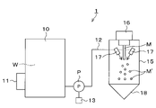
- FIG. 1 schematically shows an example of an apparatus 1 applied to the production of a metal powder by a water atomizing method.
- the metal as a raw material is melted in a crucible and kept at a temperature equal to or higher than the melting point of the metal by a heat insulating device.
- a hole for hot water is provided at the bottom of the crucible, and a circular perforation for receiving a molten metal flow is provided at the upper part of the chamber. It is appropriate to provide a rectifying tube from the perforation to the chamber. It is preferable that the rectifying tube is an annular member having a diameter slightly larger than that of the circular perforated portion, because a molten metal flow can be introduced into the chamber.
- the molten metal M flows down into the chamber (inside the atomizing device 15) from the upper supply unit 16.
- the chamber may be provided with an inert gas valve to suppress oxidation to create an inert gas atmosphere.
- the inert gas include nitrogen gas and argon gas.
- the tank 10 contains water W, which is an example of a fluid, and the water W in the tank 10 is cooled to a desired temperature by the cooler 11 mounted on the tank 10.
- the water W in the tank 10 is sent to the atomizing device 15 which is a treatment mechanism through the pipe 12.
- the pipe 12 is provided with a pump P having a discharge pressure of 175 MPa or more, and by operating the pump P, water W having a discharge pressure of 175 MPa or more is supplied to the atomizing device 15 through the pipe 12.
- the pump P is provided with a pressure adjusting mechanism 13 that gradually reduces the discharge pressure of the fluid (water W) from the pump P.
- a pressure adjusting mechanism 13 that gradually reduces the discharge pressure of the fluid (water W) from the pump P.
- the pump P for having such a discharge pressure is preferably a constant capacity type pump, but this is merely an example and is not affected by the method as long as it can generate a high pressure. Further, as the substance to be pressurized, water or oil can be appropriately selected as long as it can be atomized, but it is preferable to use water from the viewpoint of cost.
- the pressure used for atomization is as high as possible.
- the pressure as described in Patent Document 1 and the like has been used, but in order to meet the recent demand for smaller particles, the discharge pressure should be at least 150 MPa or more, preferably 175 MPa or more. Is preferable.
- the discharge pressure can be adjusted by adjusting the water supply amount and pressure setting, the number of injection slits and water supply ports, and the size of the diameter.
- the pressurization is gradually increased in order to reduce the load on the device, that is, the pressurization is gradually increased.
- the fluid (water W) pressurized via the pump P is ejected from the nozzle 17 via the pressure resistant pipe (pipe 12) and collides with the molten metal flow.
- This pressure resistant pipe must be able to withstand the pressure of passing substances (mainly fluids).
- Specific examples thereof include metal pipes and pressure-resistant resin hoses (examples of pressure-resistant resins include polyacetate, polyoxymethylene, and polyamide).
- the molten metal flows down to start atomization.
- Injecting water W water jet
- whose injection pressure is adjusted by the pump P is injected into the molten metal M that has flowed down through the nozzle 17 provided in the nozzle header to divide the molten metal flow and further cool it.
- the position where the molten metal flow M and the jet water W (water jet) come into contact is set to a position separated from the molten metal guide nozzle by an appropriate distance, so that the molten metal flow is cooled to near the melting point by heat radiation. It is preferable from the viewpoint and from the viewpoint of preventing the splashed water of the jet water from coming into contact with the molten metal guide nozzle.
- the molten metal flow reaches the atomized portion by its own weight, and the metal powder M'divided by the mechanical impact and quenching by the jet flow of the crushing liquid can be obtained.
- the metal powder M'produced in this way is collected in the lower part 18 of the chamber together with water.
- the pump P is stopped to stop the device, but if the process of reducing the discharge pressure applied to the device at this time is not properly managed, the pipe 12 is particularly 10 m or more. If this is the case, the pipe 12 will be torn. Specifically, it is preferable to gradually reduce the pressure as in the case of pressurizing.
- the pressure removed within 30 seconds after the start of the stop operation is 25% or less (residual pressure (discharge pressure A 1 MPa before the start of the stop operation of the pump P).
- the ratio of the discharge pressure A 2 MPa after 30 seconds (A 2 / A 1 )) is 75% or more), preferably 20% or less (residual pressure is 80% or more), and more preferably 15% or less (residual).
- the pressure is preferably 85% or more).
- the pressure to be removed within 2 minutes after the start of the stop operation is 90% or less (residual pressure (the ratio of the discharge pressure A 3 MPa after 2 minutes to the discharge pressure A 1 MPa before the start of the stop operation of the pump P (A). 3 / A 1 )) is preferably 10% or more), preferably 85% or less (residual pressure 15% or more), and more preferably 80% or less (residual pressure is 20% or more).
- residual pressure the ratio of the discharge pressure A 3 MPa after 2 minutes to the discharge pressure A 1 MPa before the start of the stop operation of the pump P (A). 3 / A 1 )
- the damage to the pipe 12 can be reduced, the life of the pipe material can be extended, and the replacement cost and labor cost can be reduced, so that the productivity of water atomization can be improved. It is preferable because it can be improved.
- the pressure adjusting mechanism 13 that gradually reduces the discharge pressure of the fluid (water W) from the pump P, for example, by equipping a plurality of diaphragm pumps and gradually reducing the number of operating units of the plurality of diaphragm pumps.
- a mechanism for gradually reducing the discharge pressure can be considered.
- the discharge pressure may be gradually reduced by controlling the operating capacity of the diaphragm pump itself by the inverter.
- the number control for controlling the number of operating units of a plurality of diaphragm pumps and the inverter control may be combined.
- Water atomization was carried out in a nitrogen atmosphere at a water pressure of 200 MPa for 30 minutes while dropping the molten metal melted by heating iron, silicon metal and ferrochrome to 1500 ° C or higher by inductive heating from a tundish furnace.
- This high-pressure water was sprayed from a metal nozzle connected to a pressure-resistant hose (made of polyacetate, inner diameter 7 to 13 mm: nominal value) connected to a pump (manufactured by Sugino Machine Limited).
- the 30 minutes includes the time required for boosting to the set pressure and the time required for the stop operation after the atomization is completed.
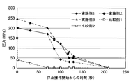
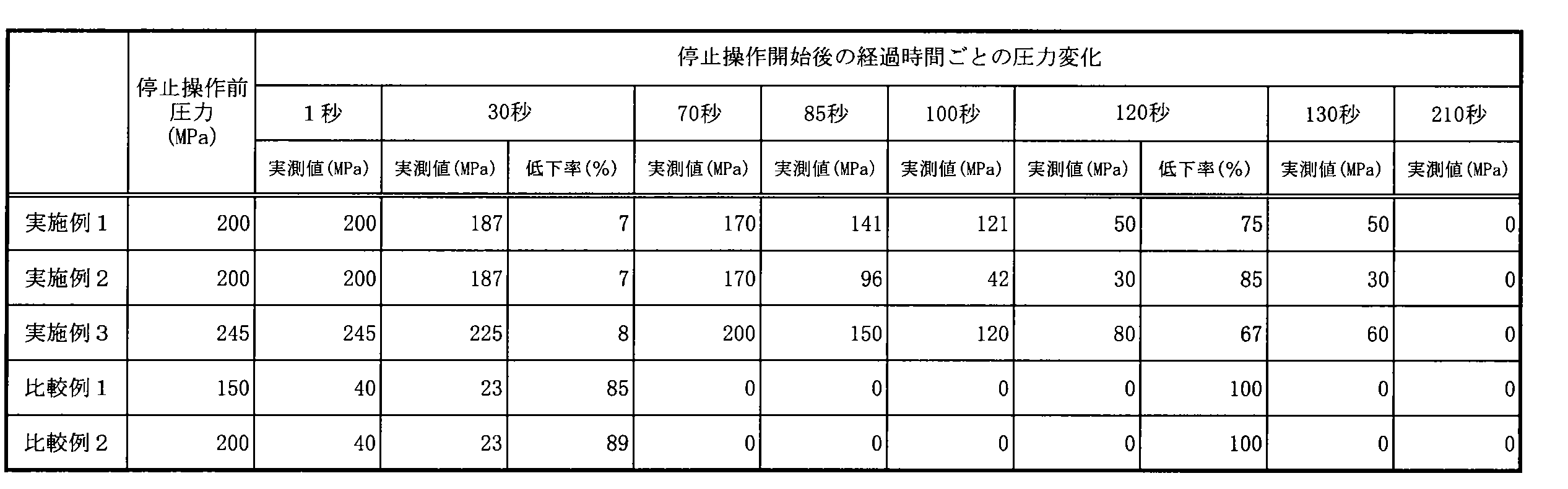
- the pressure was reduced from 200 MPa to 187 MPa over 30 seconds (residual pressure was 93.5%), reduced to 170 MPa in the next 40 seconds, reduced to 141 MPa in the next 15 seconds, and then reduced to 141 MPa in the next 15 seconds.
- the pressure was reduced to 121 MPa in the next 20 seconds (residual pressure was 25%), maintained at 50 MPa for 10 seconds, and then reduced to 0 MPa over 80 seconds.
- the total time of the depressurization process (from the start to 0 MPa) was 210 seconds.
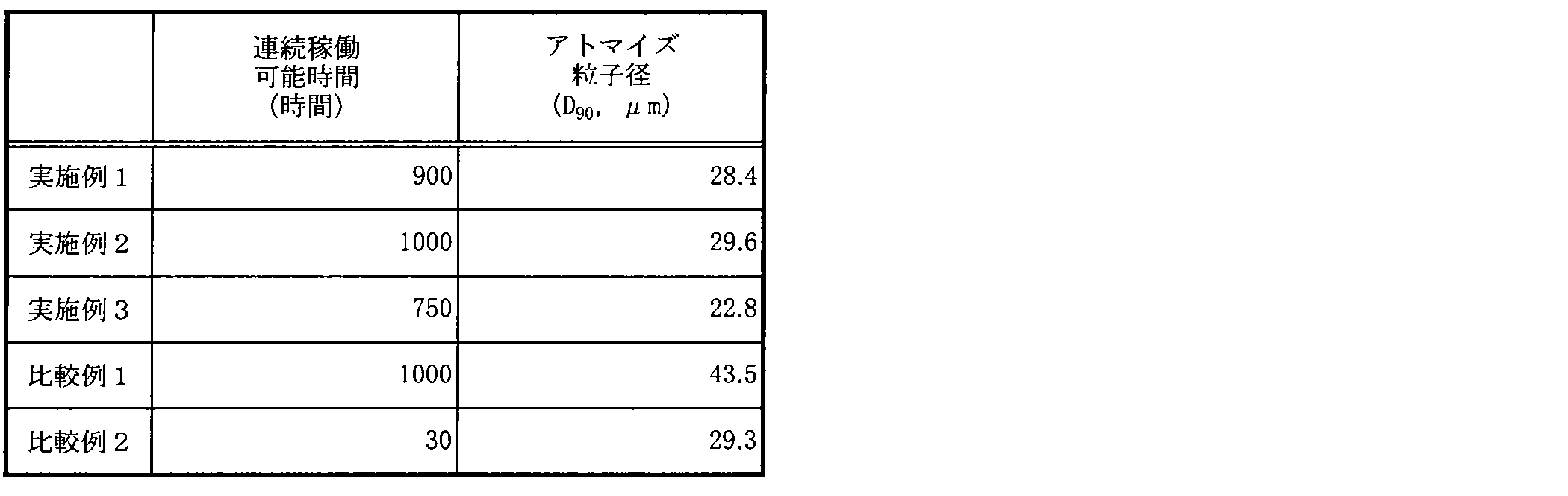
- the pressure resistant hose When the water atomizing operation for 30 minutes as described above was counted as one time and evaluated, the pressure resistant hose could be operated for 1800 times (operating time 900 hours) without being broken. Moreover, when the 90% cumulative particle diameter (D 90 diameter) of the obtained metal powder was measured by the laser diffraction scattering type particle size distribution measurement, it was 28.4 ⁇ m.
- the obtained metal powder was subjected to SEM observation using S-4700 manufactured by Hitachi High-Technologies Corporation at an acceleration voltage of 3 kV and a magnification of 1,000 times. The results are shown in FIG.
- Example 1 The operation of Example 1 was repeated except that the speed of depressurization was changed in Example 1.
- the pressure resistant hose was able to carry out the water atomization operation without breaking for 2000 times (operating time 1000 hours). Moreover, when the 90% cumulative particle diameter (D 90 diameter) of the obtained metal powder was measured, it was 29.6 ⁇ m.
- the decompression process of Example 2, the operating time of the pressure-resistant hose, and the D90 diameter of the obtained metal powder are summarized in Tables 1 and 1 and Table 2 below.
- Example 1 the same operation was repeated except that the pressure of the water to be atomized was set to 245 MPa and the speed of depressurization was changed.
- the pressure resistant hose was able to carry out the water atomization operation without breaking for 1500 times (operating time: 750 hours).
- the 90% cumulative particle diameter (D 90 diameter) of the obtained metal powder was measured, it was 22.8 ⁇ m.
- the decompression process of Example 3, the operating time of the pressure-resistant hose, and the D90 diameter of the obtained metal powder are summarized in Tables 1 and 1 and Table 2 below.
- Example 1 the pressure of the water to be atomized was set to 150 MPa, the stop operation was performed all at once, and the atomization was performed in the same manner except that the pressure was reduced in 70 seconds.
- the pressure-resistant hose was able to carry out the water atomization operation without breaking for 2000 times (operating time 1000 hours), but the pressurized pressure was small, so the particles became relatively large, and it was obtained.
- the 90% cumulative particle size (D 90 diameter) of the metal powder was measured and found to be 43.5 ⁇ m.
- the decompression process of Comparative Example 1, the operating time of the pressure-resistant hose, and the D90 diameter of the obtained metal powder are summarized in Tables 1 and 1 and Table 2 below.
- FIG. 2 shows the results of SEM observation of the obtained metal powder in the same manner as in Example 1.
- Example 1 the stop operation was performed at once in the same manner as in Comparative Example 1, and the atomization was performed in the same manner except that the pressure was reduced in 70 seconds.
- the D90 diameter of the obtained particles was 29.3 ⁇ m, which was the same as in Examples 1 and 2, but the pressure-resistant hose ruptured after only 60 times (operating time: 30 hours).
- the present invention can be used, for example, in the field of manufacturing metal powder.
Landscapes
- Engineering & Computer Science (AREA)
- Mechanical Engineering (AREA)
- General Engineering & Computer Science (AREA)
- Manufacture Of Metal Powder And Suspensions Thereof (AREA)
Abstract
175MPa以上の吐出圧力を有するポンプの運転方法であって、前記吐出を停止する操作を開始後、徐々に減圧する、ポンプの運転方法である。微細な金属粒子を得るのに好適な、吐出圧力175MPa以上における水アトマイズをランニングコストを抑えながら実施することが出来る。例えば、ポンプを175MPa以上の吐出圧力A1MPaで運転させて流体の吐出を行っているとき、前記吐出を停止する操作を開始してから30秒経過後の吐出圧力をA2MPaとしたときのA2/A1が0.75以上である。
Description
本発明は、金属溶湯の細分化処理等に好適に利用されるポンプの運転方法と、該運転方法を用いる装置に関する。
電子部品用途として広く利用されているマイクロメートルオーダーの金属粒子は、湿式還元法やアトマイズ法により生産されている。湿式還元法で作成される金属粒子の場合、化学反応を用いて粒子を形成するため、完全には使用した薬剤等の不純物成分を金属粒子から除去しきれないと言う問題があり、高い導電性を必要とされる用途においては必ずしも歓迎されるものではない。
一方、アトマイズ法による金属粒子の作成においては、大きく分けて水アトマイズ法とガスアトマイズ法があり、合金粉末の製造にはガスアトマイズ法、鉄系粉末の製造には水アトマイズ法が使用される場合が多い。これらアトマイズ法による製造は、電子部品の小型化に伴い微細な粒子が指向されるようになっている。一般的に、アトマイズ法により微細な粒子を得るには、高圧かつ大流量の噴霧媒を噴射する方法がとられている。とりわけ水アトマイズ法とガスアトマイズ法では、水アトマイズ法は製造コストが比較的低く抑えることが出来、粒子の冷却効率が高く、形状は不定形になりがちであるのに対し、ガスアトマイズ法は、アルゴンや窒素などの不活性ガスを用いるために製造コストが高めになるが、球状の粒子を得やすいという特徴がある。
例えば特許文献1では、鉛直方向に落下する溶融金属に対して加圧された圧力が0.5~22MPa、水温が150~374℃である亜臨界状態の水を噴射して衝突させ、非晶化率が90%以上になる軟磁性金属粉末を製造する方法が開示されている。また、特許文献2においては、本出願人が溶融金属粒の粉砕を、115MPaの水圧で行った例を開示している。
特許文献1および2に開示されている製造方法はアトマイズ法の中でも、水アトマイズ法に関するものであり、特許文献1の場合、噴霧される水の加圧圧力は0.5~22MPaであって、得られる鉄合金粒子の粒子径はおおよそ30~40μm程度である旨記載がされている。また、本出願人は銅について115MPaの水圧を用いて水アトマイズを行い、得られる粒子のD50粒子径が3.5μm程度であることを見いだした。
ここで、さらに微細な粒子を得るためには、粉砕の際に用いる噴霧液の加圧圧力をより高くすれば足りそうなことは容易に想像しうる。
本出願人が特許文献2で述べたとおり、従来のアトマイズ法においては、加圧する圧力が比較的小さかったため、粉砕力が十分とはいえず、微細な粒子を得ることが困難、もしくは得られたとしても所望する粒子の収量は極めて少ないものであり、コストパフォーマンスは高いものではなかった。本出願人はかような問題を解決するには、より高圧な噴霧媒体を用いて、粒子の微細化をさらに進める必要があることに想到した。
特許文献2においては、微細な金属粒子を得る方法として、噴霧圧が115MPa以上のものとする提案を行った。しかし、さらに微細なものとするには、より高圧である175MPa以上の領域において、安定した粒子を効率よく得るようにする必要があった。しかし、本発明者らの検討によれば、こうした高圧で粉砕を行おうとすると、ポンプから吐出される水により各種部材に多大な負荷をかけてしまうことから、こうした周辺部材の劣化が著しく、ランニングコストの著しい増大を招くおそれがあることがわかってきた。特に、高圧の流体が流れる配管が長い場合、配管が断裂しやすい傾向があり、いったん配管が断裂してしまうと、生産を停止せざるを得なくなるため、生産性が著しく悪くなるという問題がある。こうした課題を解決しなければ、水アトマイズ法による微細な粒子の製造を工業的に行うのは著しく困難になる可能性がある。
本発明は、上述の要請に応えるべくなされたものであって、周辺部材へかける負荷が小さく、水アトマイズ法による微細な金属粒子の供給において、ランニングコストを低減しうるポンプの運転方法、及びそのような運転方法が組みこまれた装置を提供することを目的とした。
本発明者は、当該課題の解決に際して様々な検討をなす中で、高圧噴霧を行った場合には特に噴霧媒体が通過する部分の劣化が著しく、特に噴霧圧力を175MPa以上にした場合にその劣化が極めて著しく発生することが多いことを見いだした。その発生事例を詳細に検討したところ、特に金属粒子の生産終了後において噴霧媒体の吐出圧力を減圧する工程が劣化に大きく影響していることが確認され、この減圧を特定の条件において行うことで、周辺部材の長寿命化を図ることが出来るので、ランニングコストの著しい改善が得られることを見いだし、本発明を完成させた。
すなわち、本発明における第1の発明は、175MPa以上の吐出圧力を有するポンプの運転方法であって、前記吐出を停止する操作を開始後、徐々に減圧する、ポンプの運転方法である。
第2の発明は、175MPa以上の吐出圧力を有するポンプの運転方法であって、ポンプを175MPa以上の吐出圧力A1MPaで運転させて流体の吐出を行っているとき、前記吐出を停止する操作を開始してから30秒経過後の吐出圧力をA2MPaとしたときのA2/A1が0.75以上である、ポンプの運転方法である。
第3の発明は、175MPa以上の吐出圧力を有するポンプの運転方法であって、ポンプを175MPa以上の吐出圧力A1MPaで運転させ流体の吐出を行っているとき、前記吐出を停止する操作を開始してから2分経過後の吐出圧力をA3MPaとしたときのA3/A1が0.10以上である、ポンプの運転方法である。
第4の発明は、前記ポンプから吐出される流体が水である、第1~第3のいずれかの発明に記載したポンプの運転方法である。
第5の発明は、前記ポンプから吐出される流体は、金属溶湯を細分化するために用いられる、第1~第4のいずれかの発明に記載されたポンプの運転方法である。
第6の発明は175MPa以上の吐出圧力を有するポンプと、ポンプから吐出された流体を送る配管と、配管によって送られた流体を吐出させる処理機構を有し、ポンプからの流体の吐出圧力を漸次小さくする圧力調整機構を備えた装置である。
第7の発明は、前記圧力調整機構は、ポンプを175MPa以上の吐出圧力A1MPaで運転させ流体の吐出を行っているとき、前記吐出を停止する操作を開始してから30秒経過後の吐出圧力をA2MPaとしたときのA2/A1を0.75以上に調整できる機構である、第6の発明に記載された装置である。
第8の発明は、前記ポンプから吐出される流体が水である、第6または第7の発明に記載された装置である。
第9の発明は、前記ポンプから吐出される流体は金属溶湯を細分化するために用いられるものである、第6~第8の発明のいずれかに記載の装置である。
本発明によれば、微細な金属粒子を得るのに好適な、吐出圧力175MPa以上における水アトマイズをランニングコストを抑えながら実施することが出来る。
本明細書においては、実施の形態の一例として、水アトマイズ法による金属粉末の製造に適用した装置の例について示す。
まず、原料である金属材料を溶解し、溶融金属とする。原材料として使用する金属材料としては、従来から粉末として使用されている純金属、合金、銑鉄等がいずれも適用できる。なお、金属材料の溶解方法はとくに限定する必要はないが、電気炉、真空溶解炉等の、常用の溶解手段がいずれも適用できる。溶解された溶融金属は、溶解炉からタンディッシュ等の容器に移され、水アトマイズ金属粉末製造装置内で、水アトマイズされた金属粉末とする。
対象とする金属として具体的には、元素周期表第2族から第15族の元素のうちの1種以上が挙げられ、好ましくはAu、Ag、Cu、Pd、Ni、Co、Al、Si、P、B、Ti、Cr、Fe、Zn、In、Sn、Te、Bi、Mg、Mnのうちの1種以上が挙げられる。これらの金属を単独で使用して金属粉末としてもよいし、複数を使用して合金粉末としてもよい。なお、これらの金属には、主とする元素以外の元素を、原料由来などにより不純物として含む場合があることは言うまでもない。
得られる粒子(金属粉末)の粒子径はレーザー回折散乱式粒度分布測定(SYMPATEC社製HEROS&RODOSを用い、窒素ガスを使用して測定時の分散圧5barとする)により評価する。粒子径は体積基準の累積90%粒子径(D90値)で評価する。通常は、体積基準の累積50%粒子径(D50値)で確認することが多いが、このD50値とすると、一部のイレギュラーな粒子の影響を受けやすくなり、単純な粒子径比較が出来ない場合があるので、本明細書では大部分の粒子をカウントすることになるD90径を採用する。ただし、本発明で得られる粒子はその製造方法に起因して、不定形となる場合があるが、装置に付属したプログラムに沿った解析で粒子径評価を行うことを許容する。
本方法により得られる金属、合金粒子(金属粉末)における酸素量は0.1~1.5質量%であり、好ましくは0.15~0.85質量%である。こうした測定は市販の酸素・窒素・水素測定装置(例えば堀場製作所製EMGA-930)、酸素・窒素測定装置(例えば堀場製作所製EMGA-920)などを使用すれば確認できる。
以下、本発明の一実施形態について、図面を参照しながら説明する。なお、本明細書および図面において、実質的に同一の機能構成を有する要素においては、同一の符号を付することにより重複説明を省略する。図1に、水アトマイズ法による金属粉末の製造に適用した装置1の一例を模式的に示す。
アトマイズ装置15では、原料である金属はるつぼ内で溶解され、保温装置により金属融点以上の温度に保持されている。るつぼの底部には出湯のための孔が設けられており、チャンバー上部には溶融金属流を受ける円形の穿孔部が設けられている。穿孔部からチャンバーへは整流管を設けることが適当である。整流管は円形の穿孔部よりも若干大きな径の環状部材にすることで、チャンバー内に溶融金属流を導入できるようになるので好ましい。
金属溶湯はチャンバー内(アトマイズ装置15内)に、上方の供給部16から溶融金属Mが流下するようになっている。なお、チャンバー内は、場合により酸化を抑制するために不活性ガスバルブをもうけて、不活性ガス雰囲気とすることも出来る。なお、不活性ガスとしては、窒素ガス、アルゴンガスが例示できる。
また、タンク10には、流体の一例である水Wが入っており、タンク10に装着された冷却器11により、タンク10内の水Wが所望の温度に冷却されている。タンク10内の水Wは、配管12を通じて、処理機構であるアトマイズ装置15に送られている。配管12には、175MPa以上の吐出圧力を有するポンプPが設けられており、このポンプPの稼働によって、175MPa以上の吐出圧力にされた水Wが配管12を通じてアトマイズ装置15に供給される。
ポンプPは、ポンプPからの流体(水W)の吐出圧力を漸次小さくする圧力調整機構13を備えている。この圧力調整機構13で、ポンプPの稼働を制御することにより、ポンプPからの流体(水W)の吐出圧力が適宜調整される。
こうした吐出圧力を有するためのポンプPは、定容量型のポンプであることが好ましいが、これは例示に過ぎず、高圧力を発生させることが出来るものであれば、方式には影響されない。また、加圧する物質は、アトマイズを行いうるものであれば、水や油など適宜選択することが出来るが、コストの面からみて水を使用することが好ましい。
ここで、得られる金属粒子の粒子径をできるだけ小さくするためには、アトマイズに使用される圧力をできるだけ高いものとすることが好ましい。元来は特許文献1などに記載されているような圧力のものが使用されてきたが、昨今の小粒子化の要請に応えるには、少なくとも吐出圧力としては150MPa超、好ましくは175MPa以上とすることが好ましい。この際、水の供給量と圧力の設定、噴射スリットや給水口の数、径の大きさを調整することで吐出圧力を調整することが出来る。
加圧は装置への負荷を低減するため徐々に増大させる、すなわち加圧を徐々にあげていくことが好ましい。増加に際しては開始操作30秒の段階で設定圧力の75%以下、好ましくは50%以下になるように設定することが好ましい。
そして、ポンプPを介して加圧された流体(水W)は、耐圧配管(配管12)を経由してノズル17から噴射され、溶融金属流に衝突される。この耐圧配管は、通過する物質(主として流体)の通過時の圧力に耐えられるものでなければならない。具体的には金属配管や耐圧樹脂(耐圧樹脂の例としては、ポリアセテート、ポリオキシメチレン及びポリアミドが挙げられる)ホースが例示できる。
そして、設定した圧力に達してから溶融金属を流下してアトマイズを開始する。
流下させた溶融金属Mに対し、ノズルヘッダに設けられたノズル17を介して、ポンプPにより噴射圧力を調整された噴射水W(水ジェット)を噴射し、該溶融金属流を分断、更に冷却して金属粉末とする。なお、溶融金属流Mと噴射水W(水ジェット)とが接触する位置は、溶湯ガイドノズルから適正な距離だけ離れた位置とすることが、溶融金属流を熱放射により融点近傍まで冷却するという観点、および噴射水の飛び水が溶湯ガイドノズルに接触するのを防ぐという観点から好ましい。るつぼの出湯孔を解放すると、溶融金属流は自重により、アトマイズ部に到達し、粉砕する液体のジェット流によって、機械的衝撃と急冷を受けて分断された金属粉末M‘を得ることが出来る。こうして製造された金属粉末M‘は、水と一緒になって、チャンバー下部18に溜まる。
流下させた溶融金属Mに対し、ノズルヘッダに設けられたノズル17を介して、ポンプPにより噴射圧力を調整された噴射水W(水ジェット)を噴射し、該溶融金属流を分断、更に冷却して金属粉末とする。なお、溶融金属流Mと噴射水W(水ジェット)とが接触する位置は、溶湯ガイドノズルから適正な距離だけ離れた位置とすることが、溶融金属流を熱放射により融点近傍まで冷却するという観点、および噴射水の飛び水が溶湯ガイドノズルに接触するのを防ぐという観点から好ましい。るつぼの出湯孔を解放すると、溶融金属流は自重により、アトマイズ部に到達し、粉砕する液体のジェット流によって、機械的衝撃と急冷を受けて分断された金属粉末M‘を得ることが出来る。こうして製造された金属粉末M‘は、水と一緒になって、チャンバー下部18に溜まる。
溶融金属Mの流下が終了してから、ポンプPを停止して装置を停止させるが、この際の装置にかかる吐出圧力を下げていく工程を適切に管理しなければ、特に配管12が10m以上となってしまっている場合、配管12に断裂が生じてしまう。具体的には加圧するときと同様に徐々に圧力を下げていくことが好ましい。
そこで、圧力調整機構13でポンプPの稼働を制御することにより、例えば、停止操作開始後30秒間に除去する圧力が25%以下(残存圧力(ポンプPの停止操作開始前の吐出圧力A1MPaに対する、30秒経過後の吐出圧力A2MPaの割合(A2/A1))は75%以上)、好ましくは20%以下(残存圧力は80%以上)、より好ましくは15%以下(残存圧力は85%以上)にすることが好ましい。また例えば、停止操作開始後2分間に除去する圧力が90%以下(残存圧力(ポンプPの停止操作開始前の吐出圧力A1MPaに対する、2分経過後の吐出圧力A3MPaの割合(A3/A1))は10%以上)、好ましくは85%以下(残存圧力15%以上)、より好ましくは80%以下(残存圧力は20%以上)とすることが好ましい。こうすることによって、配管12に対するダメージを低減することが出来、配管素材の長寿命化を図ることができ、ひいては交換にかかるコストや人件費を低減することが出来るので、水アトマイズの生産性を向上させることが出来るので好ましい。
ポンプPからの流体(水W)の吐出圧力を漸次小さくする圧力調整機構13の具体例としては、例えばダイアフラムポンプを複数台装備し、それら複数のダイアフラムポンプの稼働台数を徐々に減らすことで、吐出圧力を漸次小さくする機構が考えられる。また、ダイアフラムポンプ自体の稼働能力をインバータ制御することで、吐出圧力を漸次小さくするようにしても良い。また、複数のダイアフラムポンプの稼働台数を制御する台数制御とインバータ制御を組み合わせても良い。
以上、本発明の実施形態の一例について説明したが、本発明はかかる例に限定されない。当業者であれば、特許請求の範囲に記載された技術的思想の範疇内において、各種の変更例または修正例に想到しうることは明らかであり、それらについても当然に本発明の技術的範囲に属するものと了解される。
鉄とシリコンメタル、フェロクロムを誘導式加熱により1500℃以上に加熱して溶解した溶湯をタンディッシュ炉から落下させながら、水圧200MPaにおいて窒素雰囲気中で水アトマイズを30分実施した。この高圧水はポンプ(株式会社スギノマシン製)に接続した耐圧ホース(ポリアセテート製、内径は7~13mm:公称値)に接続した金属製のノズルから噴射した。30分には、設定圧力に至る昇圧にかかる時間と、アトマイズ終了後の停止操作にかかる時間を含んでいる。減圧の際には、200MPaから30秒かけて187MPaに減圧し(残存圧力は93.5%)、次の40秒で170MPaに減圧し、次の15秒で141MPaに減圧し、次の15秒で121MPaに減圧し、次の20秒で50MPaに減圧し(残存圧力は25%)、50MPaで10秒間維持し、そしてその後、80秒かけて0MPaに減圧した。減圧プロセス(スタートから0MPaになるまで)の全体時間は210秒であった。
以上のような30分の水アトマイズ操業を1回とカウントして評価したところ、耐圧ホースは1800回(動作時間900時間)の間破れることなく、水アトマイズ操業を実施することができた。また、得られた金属粉末の90%累積粒子径(D90径)をレーザー回折散乱式粒度分布測定により測定したところ、28.4μmであった。
以上の減圧プロセスと、耐圧ホースの動作時間及び得られた金属粉末のD90径を、後記表1及び図1、並びに表2にまとめた。
また、得られた金属粉末について、株式会社日立ハイテクノロジーズ製S-4700を用い、加速電圧3kV、倍率1千倍でSEM観察を行った。結果を図2に示す。
実施例1において減圧の早さを変更した以外は実施例1の操作を繰り返した。耐圧ホースは2000回(動作時間1000時間)の間破れることなく、水アトマイズ操業を実施することができた。また、得られた金属粉末の90%累積粒子径(D90径)を測定したところ、29.6μmであった。実施例2の減圧プロセスと、耐圧ホースの動作時間及び得られた金属粉末のD90径を、後記表1及び図1、並びに表2にまとめた。
実施例1において、アトマイズを行う水の圧力を245MPaとし減圧の早さを変更した以外は同様の操作を繰り返した。耐圧ホースは1500回(動作時間750時間)の間破れることなく、水アトマイズ操業を実施することができた。また、得られた金属粉末の90%累積粒子径(D90径)を測定したところ、22.8μmであった。実施例3の減圧プロセスと、耐圧ホースの動作時間及び得られた金属粉末のD90径を、後記表1及び図1、並びに表2にまとめた。
実施例1において、アトマイズを行う水の圧力を150MPaとして、停止操作を一挙に行い、圧力低下を70秒で行った以外は同様にアトマイズを行った。耐圧ホースは2000回(動作時間1000時間)の間破れることなく、水アトマイズ操業を実施することができたが、加圧した圧力が小さいため、粒子は比較的大きなものとなってしまい、得られた金属粉末の90%累積粒子径(D90径)を測定したところ、43.5μmであった。比較例1の減圧プロセスと、耐圧ホースの動作時間及び得られた金属粉末のD90径を、後記表1及び図1、並びに表2にまとめた。
また、得られた金属粉末について、実施例1と同様にSEM観察を行った結果を図2に示す。
実施例1において、停止操作を比較例1と同様に一挙に行い、圧力低下を70秒で行った以外は同様にアトマイズを行った。得られた粒子のD90径は実施例1もしくは2と同様の29.3μmであったものの、耐圧ホースはわずか60回(動作時間30時間)で断裂してしまった。
本発明は、例えば金属粉末の製造分野で利用することができる。
1 水アトマイズ法による金属粉末の製造に適用した装置
P ポンプ
M 溶融金属
M‘ 金属粉末
W 水
10 タンク
11 冷却器
12 配管
13 圧力調整機構
15 アトマイズ装置
16 供給部
17 ノズル
18 チャンバー下部
P ポンプ
M 溶融金属
M‘ 金属粉末
W 水
10 タンク
11 冷却器
12 配管
13 圧力調整機構
15 アトマイズ装置
16 供給部
17 ノズル
18 チャンバー下部
Claims (9)
- 175MPa以上の吐出圧力を有するポンプの運転方法であって、
前記吐出を停止する操作を開始後、徐々に減圧する、ポンプの運転方法。 - 175MPa以上の吐出圧力を有するポンプの運転方法であって、
ポンプを175MPa以上の吐出圧力A1MPaで運転させて流体の吐出を行っているとき、前記吐出を停止する操作を開始してから30秒経過後の吐出圧力をA2MPaとしたときのA2/A1が0.75以上である、ポンプの運転方法。 - 175MPa以上の吐出圧力を有するポンプの運転方法であって、
ポンプを175MPa以上の吐出圧力A1MPaで運転させ流体の吐出を行っているとき、前記吐出を停止する操作を開始してから2分経過後の吐出圧力をA3MPaとしたときのA3/A1が0.10以上である、ポンプの運転方法。 - 前記ポンプから吐出される流体が水である、請求項1~3のいずれか一項に記載のポンプの運転方法。
- 前記ポンプから吐出される流体は、金属溶湯を細分化するために用いられる、請求項1~4のいずれか一項に記載のポンプの運転方法。
- 175MPa以上の吐出圧力を有するポンプと、
ポンプから吐出された流体を送る配管と、
配管によって送られた流体を吐出させる処理機構を有し、
ポンプからの流体の吐出圧力を漸次小さくする圧力調整機構を備えた装置。 - 前記圧力調整機構は、ポンプを175MPa以上の吐出圧力A1MPaで運転させ流体の吐出を行っているとき、前記吐出を停止する操作を開始してから30秒経過後の吐出圧力をA2MPaとしたときのA2/A1を0.75以上に調整できる機構である、請求項6に記載の装置。
- 前記ポンプから吐出される流体が水である、請求項6または7に記載された装置。
- 前記ポンプから吐出される流体は金属溶湯を細分化するために用いられるものである、請求項6~8のいずれか一項に記載の装置。
Priority Applications (2)
| Application Number | Priority Date | Filing Date | Title |
|---|---|---|---|
| PCT/JP2020/047559 WO2022130646A1 (ja) | 2020-12-18 | 2020-12-18 | ポンプの運転方法およびポンプを備えた装置 |
| JP2021515671A JPWO2022130646A1 (ja) | 2020-12-18 | 2020-12-18 |
Applications Claiming Priority (1)
| Application Number | Priority Date | Filing Date | Title |
|---|---|---|---|
| PCT/JP2020/047559 WO2022130646A1 (ja) | 2020-12-18 | 2020-12-18 | ポンプの運転方法およびポンプを備えた装置 |
Publications (1)
| Publication Number | Publication Date |
|---|---|
| WO2022130646A1 true WO2022130646A1 (ja) | 2022-06-23 |
Family
ID=82059315
Family Applications (1)
| Application Number | Title | Priority Date | Filing Date |
|---|---|---|---|
| PCT/JP2020/047559 Ceased WO2022130646A1 (ja) | 2020-12-18 | 2020-12-18 | ポンプの運転方法およびポンプを備えた装置 |
Country Status (2)
| Country | Link |
|---|---|
| JP (1) | JPWO2022130646A1 (ja) |
| WO (1) | WO2022130646A1 (ja) |
Citations (2)
| Publication number | Priority date | Publication date | Assignee | Title |
|---|---|---|---|---|
| JPS5537527A (en) * | 1978-09-08 | 1980-03-15 | Ebara Corp | Control method for pump speed |
| JP2019214786A (ja) * | 2018-06-08 | 2019-12-19 | Dowaエレクトロニクス株式会社 | 金属粉末の製造方法および製造装置 |
-
2020
- 2020-12-18 WO PCT/JP2020/047559 patent/WO2022130646A1/ja not_active Ceased
- 2020-12-18 JP JP2021515671A patent/JPWO2022130646A1/ja active Pending
Patent Citations (2)
| Publication number | Priority date | Publication date | Assignee | Title |
|---|---|---|---|---|
| JPS5537527A (en) * | 1978-09-08 | 1980-03-15 | Ebara Corp | Control method for pump speed |
| JP2019214786A (ja) * | 2018-06-08 | 2019-12-19 | Dowaエレクトロニクス株式会社 | 金属粉末の製造方法および製造装置 |
Also Published As
| Publication number | Publication date |
|---|---|
| JPWO2022130646A1 (ja) | 2022-06-23 |
Similar Documents
| Publication | Publication Date | Title |
|---|---|---|
| JP7234392B2 (ja) | 球形非晶質合金粉末調製装置および方法 | |
| EP0282946B1 (en) | Hydrometallurgical process for producing finely divided spherical refractory metal based powders | |
| JP6299873B2 (ja) | 水アトマイズ金属粉末の製造方法 | |
| KR20160128380A (ko) | 아토마이즈 금속 분말의 제조 방법 | |
| CN102528016B (zh) | 金属注射成形用合金钢粉及其制备方法 | |
| JP6372440B2 (ja) | 水アトマイズ金属粉末の製造方法 | |
| JP4264873B2 (ja) | ガスアトマイズ法による微細金属粉末の製造方法 | |
| CN101767203B (zh) | 一种微细球形储氢合金粉末的制备方法 | |
| CN106891015A (zh) | 一种微晶、非晶态金属粉末制造装置及其制造方法 | |
| CN111500942B (zh) | 一种高氮含量无磁不锈钢粉末及其制备方法 | |
| CN113547126A (zh) | 一种防止导流管堵塞的紧密耦合气雾化制细粉方法 | |
| CN111712342A (zh) | 用于使用推力器辅助等离子体雾化以大规模成本有效地生产超细球形粉末的方法 | |
| JP6372442B2 (ja) | 水アトマイズ金属粉末の製造方法 | |
| KR20040067608A (ko) | 금속 분말 및 그 제조 방법 | |
| JP2020105593A (ja) | アトマイズ金属粉末の製造方法 | |
| JP6533352B1 (ja) | 高速流体噴射装置 | |
| KR101776111B1 (ko) | 지르코늄 분말 또는 지르코늄합금 분말의 제조방법 및 그에 따른 지르코늄 분말 또는 지르코늄합금 분말 | |
| Schade et al. | Atomization | |
| WO2022130646A1 (ja) | ポンプの運転方法およびポンプを備えた装置 | |
| CN110225804B (zh) | 软磁性铁粉的制造方法 | |
| KR102296910B1 (ko) | 냉각효율을 높인 비정질 자성분말 제조장치 및 이를 이용한 비정질 자성분말 제조방법 | |
| JPH07102307A (ja) | フレーク状粉末材料の製造方法 | |
| US4723993A (en) | Hydrometallurgical process for producing finely divided spherical low melting temperature metal based powders | |
| KR100819534B1 (ko) | 고압 수 분사 장치 및 이를 이용한 초 미립의 금속 분말의제조 방법 | |
| KR20000049741A (ko) | 고압수분사법에 의한 비정질 금속분말의 제조방법. |
Legal Events
| Date | Code | Title | Description |
|---|---|---|---|
| ENP | Entry into the national phase |
Ref document number: 2021515671 Country of ref document: JP Kind code of ref document: A |
|
| 121 | Ep: the epo has been informed by wipo that ep was designated in this application |
Ref document number: 20966032 Country of ref document: EP Kind code of ref document: A1 |
|
| NENP | Non-entry into the national phase |
Ref country code: DE |
|
| 122 | Ep: pct application non-entry in european phase |
Ref document number: 20966032 Country of ref document: EP Kind code of ref document: A1 |