WO2022130500A1 - Aircraft - Google Patents
Aircraft Download PDFInfo
- Publication number
- WO2022130500A1 WO2022130500A1 PCT/JP2020/046755 JP2020046755W WO2022130500A1 WO 2022130500 A1 WO2022130500 A1 WO 2022130500A1 JP 2020046755 W JP2020046755 W JP 2020046755W WO 2022130500 A1 WO2022130500 A1 WO 2022130500A1
- Authority
- WO
- WIPO (PCT)
- Prior art keywords
- rotors
- wing
- pair
- fuselage
- landing
- Prior art date
Links
- 230000005484 gravity Effects 0.000 claims description 24
- 230000004048 modification Effects 0.000 description 6
- 238000012986 modification Methods 0.000 description 6
- 239000003381 stabilizer Substances 0.000 description 5
- 230000007423 decrease Effects 0.000 description 3
- 241000272517 Anseriformes Species 0.000 description 1
Images


Classifications
-
- B—PERFORMING OPERATIONS; TRANSPORTING
- B64—AIRCRAFT; AVIATION; COSMONAUTICS
- B64C—AEROPLANES; HELICOPTERS
- B64C29/00—Aircraft capable of landing or taking-off vertically, e.g. vertical take-off and landing [VTOL] aircraft
- B64C29/0008—Aircraft capable of landing or taking-off vertically, e.g. vertical take-off and landing [VTOL] aircraft having its flight directional axis horizontal when grounded
- B64C29/0016—Aircraft capable of landing or taking-off vertically, e.g. vertical take-off and landing [VTOL] aircraft having its flight directional axis horizontal when grounded the lift during taking-off being created by free or ducted propellers or by blowers
- B64C29/0025—Aircraft capable of landing or taking-off vertically, e.g. vertical take-off and landing [VTOL] aircraft having its flight directional axis horizontal when grounded the lift during taking-off being created by free or ducted propellers or by blowers the propellers being fixed relative to the fuselage
-
- B—PERFORMING OPERATIONS; TRANSPORTING
- B64—AIRCRAFT; AVIATION; COSMONAUTICS
- B64C—AEROPLANES; HELICOPTERS
- B64C39/00—Aircraft not otherwise provided for
- B64C39/08—Aircraft not otherwise provided for having multiple wings
-
- B—PERFORMING OPERATIONS; TRANSPORTING
- B64—AIRCRAFT; AVIATION; COSMONAUTICS
- B64C—AEROPLANES; HELICOPTERS
- B64C1/00—Fuselages; Constructional features common to fuselages, wings, stabilising surfaces or the like
- B64C1/26—Attaching the wing or tail units or stabilising surfaces
-
- B—PERFORMING OPERATIONS; TRANSPORTING
- B64—AIRCRAFT; AVIATION; COSMONAUTICS
- B64C—AEROPLANES; HELICOPTERS
- B64C3/00—Wings
- B64C3/10—Shape of wings
- B64C3/16—Frontal aspect
Definitions
- the present invention relates to an aircraft capable of taking off and landing in the vertical direction and cruising.
- the US Patent Application Publication No. 2020/0115045 shows an aircraft called a vertical take-off and landing aircraft (VTOL).
- the aircraft set forth in US Patent Application Publication No. 2020/0115045 includes a fuselage, front and rear wings (main wings) connected to the fuselage, multiple takeoff and landing rotors located on the left and right sides of the fuselage, and a rear. It comprises a plurality of cruising rotors located above the wings.
- This aircraft uses a takeoff and landing rotor for takeoff and landing and for stop flight, and a cruise rotor for cruising.
- this aircraft uses both a takeoff and landing rotor and a cruise rotor when transitioning from a stopped flight to a cruise flight and when transitioning from a cruise flight to a stopped flight.
- two takeoff and landing rotors arranged on the left and right sides of the fuselage form a pair.
- the aircraft may have a pair of takeoff and landing rotors located in front of or at both ends of the front wing, a pair or more of takeoff and landing rotors located between the front and rear wings, and behind the rear wing. It has a pair of takeoff and landing rotors that are arranged.
- Lift is generated when air flows from the front to the wing.
- the wing of an aircraft is configured to generate a large lift near the fuselage. Therefore, a large lift can be obtained by smoothly guiding the air flowing from the front to the vicinity of the connection portion between the main wing and the fuselage.
- a pair of takeoff and landing rotors are placed in front of the rear wing (main wing) in close proximity to the fuselage.
- the pair of takeoff and landing rotors located in front of the rear wing generate an air flow from above to below in front of the rear wing. This air flow interferes with the air flow guided from the front of the rear wing to the vicinity of the connection portion between the rear wing and the fuselage. Then, the air flow guided near the connection portion between the rear wing and the fuselage may be disturbed, and the lift generated by the rear wing may be reduced.
- the present invention has been made in consideration of such a problem, and provides an aircraft capable of suppressing a decrease in lift generated by a wing when moving horizontally while using a takeoff and landing rotor.
- the purpose is.
- the first aspect of the present invention is With the torso, A front wing that is configured to generate lift during horizontal movement and is connected to the front of the fuselage. A rear wing that is configured to generate lift during horizontal movement and is connected to the rear of the fuselage. With four or more rotors configured to generate lift, Is an aircraft equipped with The four or more rotors A pair of first rotors arranged symmetrically in front of the front wing and centered on a position overlapping the center axis of the fuselage in a plan view. A pair of second rotors symmetrically arranged between the front wing and the rear wing about a position overlapping the center axis of the fuselage in a plan view. Including The distance between the fuselage and the second rotor in the width direction is longer than the distance between the fuselage and the first rotor in the width direction.
- the second aspect of the present invention is With the torso, A front wing that is configured to generate lift during horizontal movement and is connected to the front of the fuselage. A rear wing that is configured to generate lift during horizontal movement and is connected to the rear of the fuselage.
- a front wing that is configured to generate lift during horizontal movement and is connected to the front of the fuselage.
- a rear wing that is configured to generate lift during horizontal movement and is connected to the rear of the fuselage.
- the four or more rotors configured to generate lift Is an aircraft equipped with The four or more rotors include a pair of first rotors and a pair of second rotors arranged symmetrically about a position overlapping the central axis of the fuselage in a plan view.
- the distance between the center position of the rear wing and the center position between the pair of the second rotors in the front-rear direction is such that the center position of the rear wing and the center position between the pair of the first rotors are separated in the front-rear direction. Shorter than the distance to The distance between the fuselage and the second rotor in the width direction is longer than the distance between the fuselage and the first rotor in the width direction.
- a third aspect of the present invention is With the torso, A front wing that is configured to generate lift during horizontal movement and is connected to the front of the fuselage. A rear wing that is configured to generate lift during horizontal movement and is connected to the rear of the fuselage.
- a rotors configured to generate lift Is an aircraft equipped with The six or more said rotors A pair of first rotors arranged symmetrically in front of the front wing and centered on a position overlapping the center axis of the fuselage in a plan view.
- a pair of second rotors symmetrically arranged between the front wing and the rear wing about a position overlapping the center axis of the fuselage in a plan view.
- a pair of third rotors arranged symmetrically behind the rear wing and centered on a position overlapping the central axis of the fuselage in a plan view. Including The distance between the pair of the second rotors is longer than the distance between the pair of the first rotors and the distance between the pair of the third rotors.
- each invention it is possible to suppress the decrease in lift generated by the rear wing due to the operation of the second rotor.
- FIG. 1 is a perspective view of an aircraft according to the present embodiment.
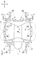
- FIG. 2 is a plan view of the aircraft according to the present embodiment.
- FIG. 3 is a plan view showing the rotation range of the propeller of the takeoff and landing rotor.
- FIG. 4 is a left side view of the aircraft according to the present embodiment.
- FIG. 5 is a front view of the aircraft according to the present embodiment.
- the vertically upward direction is referred to as an upward direction (upward)
- the vertical downward direction is referred to as a downward direction (downward).
- the moving direction when the aircraft 10 moves (flys) in the horizontal direction is the forward direction (forward)
- the opposite direction is the backward direction (rear).
- the right side direction in the width direction of the aircraft 10 is the right direction (right side)
- the left side direction in the width direction is the left direction (left side).
- viewing each part from a position directly above the aircraft 10 is referred to as a plan view of the aircraft 10. Viewing each part from a position in front of the aircraft 10 is called a front view of the aircraft 10.
- the aircraft 10 includes a fuselage 12, a front wing 14, a rear wing 16, two booms 18, eight takeoff and landing rotors 20, and two cruising rotors 22. As shown in FIG. 2, the structure of the aircraft 10 is symmetrical about a position overlapping the central axis A of the fuselage 12 extending in the front-rear direction in a plan view. In a plan view, the central axis A overlaps with the center of gravity G of the aircraft 10.
- the body 12 is long in the front-rear direction.
- the fuselage 12 has a front portion 12f located in front of the center of gravity G and a rear portion 12r located behind the center of gravity G.
- the front portion 12f is configured so that the front end side is narrowed.
- the rear portion 12r is configured so that the rear end side is narrowed.
- the main body of the body 12 may be partially covered with a fairing.
- the fuselage 12, the front portion 12f, and the rear portion 12r including this fairing are referred to.
- the front wing 14 is connected to the upper part of the front portion 12f of the fuselage 12, and is configured to generate lift when the aircraft 10 moves forward.
- the front wing 14 has a front wing body (also referred to as a horizontal stabilizer) 26 extending from the center to the left and right, and left and right elevators 28 arranged at the trailing edge of the front wing 14.
- the rear wing 16 is connected to the upper part of the rear portion 12r of the fuselage 12 via a pylon 32, and is configured to generate lift when the aircraft 10 moves forward.
- the rear wing 16 includes a rear wing body 34 extending rearward from the center, left and right elevons 36 arranged at the trailing edge of the rear wing 16, and a pair of vertical stabilizers 38 arranged at the left and right wing tips of the rear wing 16. And have.
- Each vertical stabilizer 38 has a tail body 42 (also referred to as a vertical stabilizer) and a rudder 44 arranged at the trailing edge of the vertical stabilizer 38.
- the wing area of the rear wing 16 is larger than the wing area of the front wing 14. Further, the wingspan of the rear wing 16 is longer than the wingspan of the front wing 14. With such a configuration, the lift generated by the rear wing 16 when the aircraft 10 moves forward is larger than the lift generated by the front wing 14. That is, the rear wing 16 functions as the main wing of the aircraft 10. The rear wing 16 is a swept wing that reduces air resistance.
- the front wing 14 functions as a canard of the aircraft 10.
- the front wing 14 and the rear wing 16 also function as support members for supporting the two booms 18.
- the lift generated by the rear wing 16 when the aircraft 10 moves forward may be the same as the lift generated by the front wing 14 when the aircraft 10 moves forward.
- the magnitude relationship between the lift generated by the front wing 14 and the lift generated by the rear wing 16 is appropriately determined by the position of the center of gravity G, the attitude of the aircraft during cruising, and the like. Further, the sizes (wing area, length, etc.) of the front wing 14 and the rear wing 16 are determined so that the desired lift is generated.
- the two booms 18 consist of a right boom 18 arranged to the right of the fuselage 12 and a left boom 18 arranged to the left of the fuselage 12.
- the two booms 18 form a pair and are arranged symmetrically with respect to a position overlapping the central axis A of the body 12 in a plan view.
- the two booms 18 function as support members for supporting the takeoff and landing rotor 20.
- the boom 18 on the right side is a rod member that extends from the front to the rear and curves in an arc shape toward the right (outside in the width direction).
- the right boom 18 is connected to the right wing tip of the front wing 14 and is connected to the inside of the right wing elevon 36 of the rear wing 16.
- the front end of the boom 18 on the right side is located in front of the front wing 14.
- the rear end of the boom 18 on the right side is located behind the rear wing 16.
- the boom 18 on the left side is a rod member that extends from the front to the rear and curves in an arc shape toward the left (outside in the width direction).
- the left boom 18 is connected to the left wing tip of the front wing 14 and is connected to the inside of the left wing elevon 36 of the rear wing 16.
- the front end of the boom 18 on the left side is located in front of the front wing 14.
- the rear end of the boom 18 on the left side is located behind the rear wing 16.
- the takeoff and landing rotor 20 has a rotary mast (not shown) connected to an output shaft of an electric motor (not shown) and a propeller 46 attached to the rotary mast.
- the rotary mast is arranged so as to be parallel to the vertical direction, and can rotate about an axis extending in the vertical direction.
- the propeller 46 is located above the boom 18, front wing 14, and rear wing 16. With such a structure, the propeller 46 can rotate about an axis extending in the vertical direction.
- Each takeoff and landing rotor 20 generates lift by the rotation of the propeller 46.
- the eight takeoff and landing rotors 20 include four takeoff and landing rotors 20a to 20d arranged to the right of the fuselage 12 and four takeoff and landing rotors 20a to 20d arranged to the left of the fuselage 12. ..
- the takeoff and landing rotors 20a to 20d on the right side are supported by the boom 18 on the right side.
- the takeoff and landing rotors 20a to 20d on the left side are supported by the boom 18 on the left side.
- the takeoff and landing rotors 20a to 20d on the right side and the takeoff and landing rotors 20a to 20d on the left side which are in the same position in the front-rear direction, form a pair.
- a pair of takeoff and landing rotors 20a, a front wing 14, a pair of takeoff and landing rotors 20b, a pair of takeoff and landing rotors 20c, and a rear wing. 16 and a pair of takeoff and landing rotors 20d are arranged in that order. That is, the pair of takeoff and landing rotors 20a are arranged in front of the front wing 14. Further, the pair of takeoff and landing rotors 20b are arranged between the front wing 14 and the rear wing 16 and are arranged in front of the pair of takeoff and landing rotors 20c.
- the pair of takeoff and landing rotors 20c are arranged between the front wing 14 and the rear wing 16, and are arranged behind the pair of takeoff and landing rotors 20b. Further, the pair of takeoff and landing rotors 20d are arranged behind the rear wing 16. On the other hand, as shown in FIG. 4, the takeoff and landing rotors 20a to 20d are arranged at the same height position.
- the distance between the fuselage 12 and the takeoff and landing rotor 20a in the width direction is defined as Dx.
- the distance between the fuselage 12 and the takeoff and landing rotor 20b in the width direction is defined as Dy.
- the distance between the fuselage 12 and the takeoff and landing rotor 20c in the width direction is defined as Dz.
- the starting point (or ending point) on the body 12 side of the distances Dx to Dz is the outermost position in the plan view of the outer surface of the body 12.
- the starting point (or ending point) on the takeoff and landing rotor 20 side at a distance Dx to Dz is the position of the axis of each propeller 46.
- each takeoff and landing rotor 20 is arranged so that the following first and second conditions are satisfied.
- Dy Dz ... 2nd condition
- each takeoff and landing rotor 20 may be arranged so that the following third condition is satisfied instead of the second condition.
- the distance between the pair of takeoff and landing rotors 20a is defined as Da.
- the distance at which the pair of takeoff and landing rotors 20b are separated from each other is defined as Db.
- the distance at which the pair of takeoff and landing rotors 20c are separated from each other is defined as Dc.
- the distance at which the pair of takeoff and landing rotors 20d are separated from each other is defined as Dd.
- the starting point and the ending point of the distances Da to Dd are the positions of the axes of the propellers 46.
- the takeoff and landing rotors 20 are arranged so that the following fourth and fifth conditions are satisfied.
- each takeoff and landing rotor 20 may be arranged so that the following sixth condition is satisfied instead of the fifth condition.
- Da Dd, Db ⁇ Dc ... 6th condition
- the center position Ca between the pair of takeoff and landing rotors 20a and the center position Cb between the pair of takeoff and landing rotors 20b are in front of the center of gravity G. Further, in a plan view, the center position Cc between the pair of takeoff and landing rotors 20c and the center position Cd between the pair of takeoff and landing rotors 20d are behind the center of gravity G.
- the distance between the center position Ca and the center of gravity G between the pair of takeoff and landing rotors 20a in a plan view is defined as D01. Further, in a plan view, the distance between the center position Cb and the center of gravity G between the pair of takeoff and landing rotors 20b is defined as D02. Further, in a plan view, the distance between the center position Cc and the center of gravity G between the pair of takeoff and landing rotors 20c is defined as D03. Further, in a plan view, the distance between the center position Cd and the center of gravity G between the pair of takeoff and landing rotors 20d is defined as D04.
- the takeoff and landing rotors 20 are arranged so that the following seventh condition is satisfied.
- the distance between the center position Cb between the pair of takeoff and landing rotors 20b and the center position Cw of the rear wing 16 in a plan view is defined as D11.
- the distance between the center position Cc between the pair of takeoff and landing rotors 20c and the center position Cw of the rear wing 16 is defined as D12.
- the distance between the center position Cd between the pair of takeoff and landing rotors 20d and the center position Cw of the rear wing 16 is defined as D13.
- the center position Cw of the rear wing 16 may be the center position in the front-rear direction within the center line of the rear wing 16 extending in the front-rear direction, or may be the center of gravity of the rear wing 16.
- the takeoff and landing rotors 20 are arranged so that the following eighth condition is satisfied. D12 ⁇ D11, D12 ⁇ D13 ... Eighth condition
- the pair of takeoff and landing rotors 20a are arranged immediately before the front wing 14 in a plan view.
- the rotation range 48a of the propeller 46 of the takeoff and landing rotor 20a is in contact with or away from the leading edge of the front wing 14.
- the pair of takeoff and landing rotors 20c are arranged immediately before the rear wing 16 in a plan view.
- the rotation range 48c of the propeller 46 of the takeoff and landing rotor 20c is in contact with or away from the leading edge of the rear wing 16.
- the rotation ranges 48a and 48c of the propellers 46 of the takeoff and landing rotors 20a and 20c arranged in front of the wing do not overlap with the wing.
- the two cruise rotors 22 are arranged at the rear portion 12r of the fuselage 12.
- the position of the cruising rotor 22 in the left-right direction is inside (on the fuselage 12 side) of the position of each pair of takeoff and landing rotors 20 in the left-right direction.
- the position of the cruise rotor 22 in the front-rear direction is between the pair of takeoff and landing rotors 20c and the pair of takeoff and landing rotors 20d.
- the vertical position of the axis of the cruise rotor 22 is lower than the vertical position of the propeller 46 of the takeoff and landing rotor 20.
- the cruise rotor 22 includes a rotary mast (not shown) connected to an output shaft of an electric motor (not shown), a propeller 52 attached to the front end of the rotary mast, and a propeller 52. It has a cylindrical duct 54 that surrounds it.
- the positions of the two cruising rotors 22 in the front-rear direction and the positions in the up-down direction coincide with each other. Further, the two cruise rotors 22 are arranged side by side on the left and right sides.
- One cruise rotor 22 is arranged to the right of the position overlapping the central axis A of the fuselage 12 in a plan view, and is supported by the right wing of the rear wing 16.
- the other cruise rotor 22 is arranged to the left of the position overlapping the central axis A of the fuselage 12 in a plan view, and is supported by the left wing of the rear wing 16.
- the rotary mast is arranged below the rear wing 16 so as to be parallel to the front-rear direction, and can rotate about an axis extending in the front-rear direction.
- the propeller 52 can rotate about an axis extending in the front-rear direction.
- Each cruising rotor 22 generates thrust by the rotation of the propeller 52.
- the takeoff and landing rotor 20 is used when the aircraft 10 takes off, lands, and stops.
- the cruise rotor 22 is used when the aircraft 10 is cruising.
- the takeoff and landing rotor 20 and the cruise rotor 22 are used when the aircraft 10 shifts from a stopped flight to a cruise flight, and the first speed ( ⁇ 0 km / h) or more and the second speed (> first speed) are forward. ) Is used together when moving below.
- the utilization rate of the cruising rotor 22 is gradually increased in order to accelerate. As the wing accelerates, the lift generated by the wing increases, so the usage rate of the takeoff and landing rotor 20 is gradually reduced.
- the utilization rate of the takeoff and landing rotor 20 is lowered by reducing the rotational speed of the takeoff and landing rotor 20 to reduce the lift.
- the utilization of the takeoff and landing rotor 20 is lowered by changing the pitch angle of each blade to reduce lift.
- the third speed ( ⁇ 0 km / h) or more and the fourth speed (> third speed) are forward. ) Is used together when moving below.
- the utilization rate of the cruising rotor 22 is gradually lowered in order to decelerate.
- the lift generated by the wing becomes smaller, so that the usage rate of the takeoff and landing rotor 20 is gradually increased.
- the utilization rate of the takeoff and landing rotor 20 is lowered by reducing the rotational speed of the takeoff and landing rotor 20 to reduce the lift.
- the utilization of the takeoff and landing rotor 20 is lowered by changing the pitch angle of each blade to reduce lift.
- Aircraft 10 may include four takeoff and landing rotors 20, i.e., two pairs of takeoff and landing rotors 20.
- the first pair of takeoff and landing rotors 20 are arranged in front of the front wing 14.
- the second pair of takeoff and landing rotors 20 are arranged between the front wing 14 and the rear wing 16.
- the distance between the takeoff and landing rotor 20 arranged between the front wing 14 and the rear wing 16 and the fuselage 12 in the width direction is set forward of the front wing 14.
- Each takeoff and landing rotor 20 is arranged so that the distance between the arranged takeoff and landing rotor 20 and the fuselage 12 is longer than the distance between them in the width direction.
- Aircraft 10 may include six takeoff and landing rotors 20, i.e., three pairs of takeoff and landing rotors 20.
- the first pair of takeoff and landing rotors 20 are arranged in front of the front wing 14.
- the second pair of takeoff and landing rotors 20 are arranged between the front wing 14 and the rear wing 16.
- the third pair of takeoff and landing rotors 20 are arranged behind the rear wing 16.
- the distance between the takeoff and landing rotor 20 arranged between the front wing 14 and the rear wing 16 and the fuselage 12 in the width direction is set forward of the front wing 14.
- Each takeoff and landing rotor 20 is arranged so that the distance between the arranged takeoff and landing rotor 20 and the fuselage 12 is longer than the distance between them in the width direction.
- the distance between the second pair of takeoff and landing rotors 20 arranged between the front wing 14 and the rear wing 16 is between the first pair of takeoff and landing rotors 20 arranged in front of the front wing 14.
- Each takeoff and landing rotor 20 is arranged so as to be longer than the distance between the two and the third pair of takeoff and landing rotors 20 arranged behind the rear wing 16.
- the aircraft 10 may include 10 or more takeoff and landing rotors 20, that is, five or more pairs of takeoff and landing rotors 20.
- at least a pair of takeoff and landing rotors 20 are arranged in front of the front wing 14 in a plan view. Further, in a plan view, at least a pair of takeoff and landing rotors 20 are arranged between the front wing 14 and the rear wing 16. Further, in a plan view, at least a pair of takeoff and landing rotors 20 are arranged behind the rear wing 16.
- the distance between the takeoff and landing rotor 20 arranged between the front wing 14 and the rear wing 16 and the fuselage 12 in the width direction is set forward of the front wing 14.
- Each takeoff and landing rotor 20 is arranged so that the distance between the arranged takeoff and landing rotor 20 and the fuselage 12 is longer than the distance between them in the width direction.
- each pair of takeoff and landing rotors 20 arranged between the front wing 14 and the rear wing 16 is the distance between each pair of takeoff and landing rotors 20 arranged in front of the front wing 14, and ,
- Each takeoff and landing rotor 20 is arranged so as to be longer than the distance between each pair of takeoff and landing rotors 20 arranged behind the rear wing 16.
- the first aspect of the present invention is Torso 12 and A front wing 14 configured to generate lift during horizontal movement and connected to the front portion 12f of the fuselage 12.
- a rear wing 16 configured to generate lift during horizontal movement and connected to the rear 12r of the fuselage 12.
- Four or more rotors (rotor 20 for takeoff and landing) configured to generate lift,
- An aircraft 10 equipped with The four or more rotors A pair of first rotors (rotor 20a for takeoff and landing) arranged symmetrically in front of the front wing 14 and centered on a position overlapping the central axis A of the fuselage 12 in a plan view.
- a pair of second rotors (rotors for takeoff and landing 20b, 20c) arranged symmetrically between the front wing 14 and the rear wing 16 about a position overlapping the central axis A of the fuselage 12 in a plan view. )When, Including The distance (Dy, Dz) between the body 12 and the second rotor in the width direction is longer than the distance (Dx) between the body 12 and the first rotor in the width direction.
- the operation of the second rotor causes a downward air flow and a horizontal direction. Air is guided from the front to the rear wing 16 as it moves to.
- at least the distance (Dy, Dz) between the fuselage 12 and the second rotor in the width direction is the distance between the fuselage 12 and the first rotor (rotor 20a for takeoff and landing) in the width direction (Dx).
- the distance (Db, Dc) between the pair of the second rotors may be longer than the distance (Da) between the pair of the first rotors.
- the center of gravity G of the aircraft 10 is located between the front wing 14 and the rear wing 16.
- the distance (D02, D03) at which the center positions Cb and Cc between the center of gravity G and the pair of the second rotors are separated in the front-rear direction is such that the center position Ca between the center of gravity G and the pair of the first rotors is front-rear. It may be shorter than the distance (D01) separated in the direction.
- the attitude of the aircraft 10 can be stabilized for the following reasons.
- the pair of first rotors (takeoff and landing rotors 20a) are arranged farther from the center of gravity G than the pair of second rotors (takeoff and landing rotors 20b, 20c). Therefore, the lift moment around the center of gravity G generated by the pair of first rotors is larger than the lift moment around the center of gravity G generated by the pair of second rotors. Further, as the pair of first rotors is separated from the fuselage 12, the moment in the roll direction becomes larger.
- the pair of first rotors arranged away from the center of gravity G is closer to the fuselage 12 than the pair of second rotors arranged closer to the center of gravity G. That is, the fuselage 12 and the first rotor are relatively close to each other. Therefore, the moment in the roll direction is relatively small. Therefore, according to the above configuration, the attitude of the aircraft 10 can be stabilized.
- a pair of rod members (boom 18) arranged symmetrically with respect to a position overlapping the central axis A of the body 12 in a plan view are provided.
- the pair of rod members may be connected to the front wing 14 and the rear wing 16 and may be curved outward in the width direction to support the pair of the first rotor and the pair of the second rotor.
- both the front wing 14 and the rear wing 16 support the rod member (boom 18), the rod is compared with the case where only one of the front wing 14 or the rear wing 16 supports the rod member. It is not necessary to increase the rigidity of the member.
- the rear wing 16 is a swept wing and
- the wing area of the rear wing 16 may be larger than the wing area of the front wing 14, or the wing width of the rear wing 16 may be longer than the wing width of the front wing 14.
- the rear wing 16 is a swept wing
- the rotation range 48c of the propeller 46 of the second rotor is 48c in a plan view.
- the leading edge of the rear wing 16 are easily separated in the front-rear direction. Therefore, the downward air flow generated by the operation of the second rotor is less likely to interfere with the rear wing 16.
- Torso 12 and A front wing 14 configured to generate lift during horizontal movement and connected to the front portion 12f of the fuselage 12.
- a rear wing 16 configured to generate lift during horizontal movement and connected to the rear 12r of the fuselage 12.
- Four or more rotors (rotor 20 for takeoff and landing) configured to generate lift,
- An aircraft 10 equipped with The four or more rotors are a pair of first rotors (takeoff and landing rotor 20b) and a pair of second rotors (takeoff and landing) arranged symmetrically about a position overlapping the central axis A of the fuselage 12 in a plan view.
- Rotor 20c included
- the distance (D12) at which the center position Cw of the rear wing 16 and the center position Cc between the pair of the second rotors are separated in the front-rear direction is the distance (D12) between the center position Cw of the rear wing 16 and the pair of the first rotors. It is shorter than the distance (D11) at which the center position Cb is separated in the front-rear direction.
- the distance (Dz) between the body 12 and the second rotor in the width direction is longer than the distance (Dy) between the body 12 and the first rotor in the width direction.
- At least the distance (Dz) at which the fuselage 12 and the second rotor (takeoff / landing rotor 20c) are separated in the width direction is such that the fuselage 12 and the first rotor (takeoff / landing rotor 20b) are separated in the width direction.
- a relatively large space is formed between the fuselage 12 and the second rotor. Therefore, the air flow guided from the front to the vicinity of the connection portion between the rear wing 16 and the fuselage 12 does not interfere with the downward air flow generated by the operation of the second rotor.
- the air flowing from the front can be smoothly guided to the vicinity of the connection portion between the rear wing 16 and the fuselage 12 where the maximum lift is generated, and as a result, the lift generated by the rear wing 16 is generated. It can be suppressed from becoming smaller.
- Torso 12 and A front wing 14 configured to generate lift during horizontal movement and connected to the front portion 12f of the fuselage 12.
- a rear wing 16 configured to generate lift during horizontal movement and connected to the rear 12r of the fuselage 12.
- Six or more rotors (rotor 20 for takeoff and landing) configured to generate lift,
- An aircraft 10 equipped with The six or more said rotors A pair of first rotors (rotor 20a for takeoff and landing) arranged symmetrically in front of the front wing 14 and centered on a position overlapping the central axis A of the fuselage 12 in a plan view.
- a pair of second rotors (rotors for takeoff and landing 20b, 20c) arranged symmetrically between the front wing 14 and the rear wing 16 about a position overlapping the central axis A of the fuselage 12 in a plan view.
- a pair of third rotors (rotor for takeoff and landing 20d) arranged symmetrically with respect to the position of the fuselage 12 overlapping the central axis A in a plan view behind the rear wing 16.
- the distance between the pair of the second rotors (Db, Dc) is longer than the distance between the pair of the first rotors (Da) and the distance between the pair of the third rotors (Dd).
- At least the distance (Db, Dc) between the pair of second rotors (takeoff and landing rotors 20b, 20c) is the distance (Da) between the pair of first rotors (takeoff and landing rotors 20a) and the pair. It is longer than the distance (Dd) between the third rotors (rotor for takeoff and landing 20d). That is, a relatively large space is formed between the fuselage 12 and the second rotor. Therefore, the air flow guided from the front to the vicinity of the connection portion between the rear wing 16 and the fuselage 12 does not interfere with the downward air flow generated by the operation of the second rotor.
- the air flowing from the front can be smoothly guided to the vicinity of the connection portion between the rear wing 16 and the fuselage 12 where the maximum lift is generated, and as a result, the lift generated by the rear wing 16 is generated. It can be suppressed from becoming smaller.
- the width of the front side and the width of the rear side of the aircraft 10 can be reduced. Therefore, the aircraft 10 can be stored in a small space.
Abstract
Description
胴体と、
水平方向移動時に揚力を発生させるように構成され、前記胴体の前部に接続される前翼と、
水平方向移動時に揚力を発生させるように構成され、前記胴体の後部に接続される後翼と、
揚力を発生させるように構成される4つ以上のロータと、
を備える航空機であって、
4つ以上の前記ロータは、
前記前翼よりも前方で、平面視において前記胴体の中心軸線と重なる位置を中心にして左右対称に配置される一対の第1ロータと、
前記前翼と前記後翼との間で、平面視において前記胴体の前記中心軸線と重なる位置を中心にして左右対称に配置される一対の第2ロータと、
を含み、
前記胴体と前記第2ロータとが幅方向に離間する距離が、前記胴体と前記第1ロータとが幅方向に離間する距離よりも長い。 The first aspect of the present invention is
With the torso,
A front wing that is configured to generate lift during horizontal movement and is connected to the front of the fuselage.
A rear wing that is configured to generate lift during horizontal movement and is connected to the rear of the fuselage.
With four or more rotors configured to generate lift,
Is an aircraft equipped with
The four or more rotors
A pair of first rotors arranged symmetrically in front of the front wing and centered on a position overlapping the center axis of the fuselage in a plan view.
A pair of second rotors symmetrically arranged between the front wing and the rear wing about a position overlapping the center axis of the fuselage in a plan view.
Including
The distance between the fuselage and the second rotor in the width direction is longer than the distance between the fuselage and the first rotor in the width direction.
胴体と、
水平方向移動時に揚力を発生させるように構成され、前記胴体の前部に接続される前翼と、
水平方向移動時に揚力を発生させるように構成され、前記胴体の後部に接続される後翼と、
揚力を発生させるように構成される4つ以上のロータと、
を備える航空機であって、
4つ以上の前記ロータは、平面視において前記胴体の中心軸線と重なる位置を中心にして左右対称に配置される一対の第1ロータ及び一対の第2ロータを含み、
前記後翼の中心位置と一対の前記第2ロータ間の中心位置とが前後方向に離間する距離が、前記後翼の中心位置と一対の前記第1ロータ間の中心位置とが前後方向に離間する距離よりも短く、
前記胴体と前記第2ロータとが幅方向に離間する距離が、前記胴体と前記第1ロータとが幅方向に離間する距離よりも長い。 The second aspect of the present invention is
With the torso,
A front wing that is configured to generate lift during horizontal movement and is connected to the front of the fuselage.
A rear wing that is configured to generate lift during horizontal movement and is connected to the rear of the fuselage.
With four or more rotors configured to generate lift,
Is an aircraft equipped with
The four or more rotors include a pair of first rotors and a pair of second rotors arranged symmetrically about a position overlapping the central axis of the fuselage in a plan view.
The distance between the center position of the rear wing and the center position between the pair of the second rotors in the front-rear direction is such that the center position of the rear wing and the center position between the pair of the first rotors are separated in the front-rear direction. Shorter than the distance to
The distance between the fuselage and the second rotor in the width direction is longer than the distance between the fuselage and the first rotor in the width direction.
胴体と、
水平方向移動時に揚力を発生させるように構成され、前記胴体の前部に接続される前翼と、
水平方向移動時に揚力を発生させるように構成され、前記胴体の後部に接続される後翼と、
揚力を発生させるように構成される6つ以上のロータと、
を備える航空機であって、
6つ以上の前記ロータは、
前記前翼よりも前方で、平面視において前記胴体の中心軸線と重なる位置を中心にして左右対称に配置される一対の第1ロータと、
前記前翼と前記後翼との間で、平面視において前記胴体の前記中心軸線と重なる位置を中心にして左右対称に配置される一対の第2ロータと、
前記後翼よりも後方で、平面視において前記胴体の前記中心軸線と重なる位置を中心にして左右対称に配置される一対の第3ロータと、
を含み、
一対の前記第2ロータ間の距離が、一対の前記第1ロータ間の距離及び一対の前記第3ロータ間の距離よりも長い。 A third aspect of the present invention is
With the torso,
A front wing that is configured to generate lift during horizontal movement and is connected to the front of the fuselage.
A rear wing that is configured to generate lift during horizontal movement and is connected to the rear of the fuselage.
With six or more rotors configured to generate lift,
Is an aircraft equipped with
The six or more said rotors
A pair of first rotors arranged symmetrically in front of the front wing and centered on a position overlapping the center axis of the fuselage in a plan view.
A pair of second rotors symmetrically arranged between the front wing and the rear wing about a position overlapping the center axis of the fuselage in a plan view.
A pair of third rotors arranged symmetrically behind the rear wing and centered on a position overlapping the central axis of the fuselage in a plan view.
Including
The distance between the pair of the second rotors is longer than the distance between the pair of the first rotors and the distance between the pair of the third rotors.
本実施形態では、航空機10として、電動モータを有するロータで揚力及び推力を発生させる電動垂直離着陸機(eVTOL)を想定する。なお、本明細書では、鉛直上向きを上方向(上方)とし、鉛直下向きを下方向(下方)とする。また、航空機10が水平方向に移動(飛行)するときの移動方向を前方向(前方)とし、その逆方向を後方向(後方)とする。また、航空機10から前方に向いた状態で、航空機10の幅方向の右側の方向を右方向(右方)とし、幅方向の左側の方向を左方向(左方)とする。また、各部を航空機10の真上の位置から見ることを航空機10の平面視という。各部を航空機10の前方の位置から見ることを航空機10の正面視という。 [1 Overall configuration of aircraft 10]
In the present embodiment, as the
Dx<Dy、Dx<Dz ・・・ 第1条件
Dy=Dz ・・・ 第2条件 In this embodiment, each takeoff and landing
Dx <Dy, Dx <Dz ... 1st condition Dy = Dz ... 2nd condition
Dy<Dz ・・・ 第3条件 In addition, each takeoff and landing
Dy <Dz ・ ・ ・ Third condition
Da<Db、Da<Dc、Dd<Db、Dd<Dc ・・・ 第4条件
Da=Dd、Db=Dc ・・・ 第5条件 In the present embodiment, in addition to the first to third conditions, the takeoff and landing
Da <Db, Da <Dc, Dd <Db, Dd <Dc ... 4th condition Da = Dd, Db = Dc ... 5th condition
Da=Dd、Db<Dc ・・・ 第6条件 In addition, each takeoff and landing
Da = Dd, Db <Dc ... 6th condition
D02<D01、D03<D01、D02<D04、D03<D04 ・・・ 第7条件 In the present embodiment, in addition to the first to sixth conditions, the takeoff and landing
D02 <D01, D03 <D01, D02 <D04, D03 <D04 ... 7th condition
D12<D11、D12<D13 ・・・ 第8条件 In the present embodiment, in addition to the first to seventh conditions, the takeoff and landing
D12 <D11, D12 <D13 ... Eighth condition
離着陸用ロータ20は、航空機10が離陸するときと着陸するときと停止飛行するときに使用される。一方、巡航用ロータ22は、航空機10が巡航するときに使用される。また、離着陸用ロータ20及び巡航用ロータ22は、航空機10が停止飛行から巡航飛行に移行する場合であって、前方に第1速度(≧0km/h)以上、第2速度(>第1速度)未満で移動する場合に併用される。この場合、加速するために、巡航用ロータ22の使用率が徐々に高くされる。加速に伴い、翼で発生させる揚力が大きくなるため、離着陸用ロータ20の使用率は徐々に低くされる。例えば、離着陸用ロータ20の使用率は、離着陸用ロータ20の回転速度を低下させて揚力を減少させることによって低くされる。又は、離着陸用ロータ20の使用率は、各ブレードのピッチ角を変更して揚力を減少させることによって低くされる。 [2 Relationship between flight conditions and rotor used]
The takeoff and landing
[3.1 変形例1]
航空機10は、4つの離着陸用ロータ20、すなわち二対の離着陸用ロータ20を備えていても良い。この場合、平面視において、第1の対の離着陸用ロータ20は、前翼14よりも前方に配置される。また、平面視において、第2の対の離着陸用ロータ20は、前翼14と後翼16との間に配置される。 [3 Modification example of aircraft 10]
[3.1 Modification Example 1]
航空機10は、6つの離着陸用ロータ20、すなわち三対の離着陸用ロータ20を備えていても良い。この場合、平面視において、第1の対の離着陸用ロータ20は、前翼14よりも前方に配置される。また、平面視において、第2の対の離着陸用ロータ20は、前翼14と後翼16との間に配置される。また、平面視において、第3の対の離着陸用ロータ20は、後翼16よりも後方に配置される。 [3.2 Modification 2]
航空機10は、10以上の離着陸用ロータ20、すなわち五対以上の離着陸用ロータ20を備えていても良い。この場合、平面視において、少なくとも一対の離着陸用ロータ20が、前翼14よりも前方に配置される。また、平面視において、少なくとも一対の離着陸用ロータ20が、前翼14と後翼16との間に配置される。また、平面視において、少なくとも一対の離着陸用ロータ20が、後翼16よりも後方に配置される。 [3.3 Modification 3]
The
上記実施形態から把握しうる技術的思想について、以下に記載する。 [4 Technical Ideas Obtained from the Embodiment]
The technical ideas that can be grasped from the above embodiments are described below.
胴体12と、
水平方向移動時に揚力を発生させるように構成され、前記胴体12の前部12fに接続される前翼14と、
水平方向移動時に揚力を発生させるように構成され、前記胴体12の後部12rに接続される後翼16と、
揚力を発生させるように構成される4つ以上のロータ(離着陸用ロータ20)と、
を備える航空機10であって、
4つ以上の前記ロータは、
前記前翼14よりも前方で、平面視において前記胴体12の中心軸線Aと重なる位置を中心にして左右対称に配置される一対の第1ロータ(離着陸用ロータ20a)と、
前記前翼14と前記後翼16との間で、平面視において前記胴体12の前記中心軸線Aと重なる位置を中心にして左右対称に配置される一対の第2ロータ(離着陸用ロータ20b、20c)と、
を含み、
前記胴体12と前記第2ロータとが幅方向に離間する距離(Dy、Dz)が、前記胴体12と前記第1ロータとが幅方向に離間する距離(Dx)よりも長い。 The first aspect of the present invention is
A
A
Four or more rotors (
An
The four or more rotors
A pair of first rotors (
A pair of second rotors (rotors for takeoff and
Including
The distance (Dy, Dz) between the
一対の前記第2ロータ間の距離(Db、Dc)が、一対の前記第1ロータ間の距離(Da)よりも長くても良い。 In the first aspect of the present invention
The distance (Db, Dc) between the pair of the second rotors may be longer than the distance (Da) between the pair of the first rotors.
前記前翼14と前記後翼16との間に前記航空機10の重心Gがあり、
前記重心Gと一対の前記第2ロータ間の中心位置Cb、Ccとが前後方向に離間する距離(D02、D03)が、前記重心Gと一対の前記第1ロータ間の中心位置Caとが前後方向に離間する距離(D01)よりも短くても良い。 In the first aspect of the present invention
The center of gravity G of the
The distance (D02, D03) at which the center positions Cb and Cc between the center of gravity G and the pair of the second rotors are separated in the front-rear direction is such that the center position Ca between the center of gravity G and the pair of the first rotors is front-rear. It may be shorter than the distance (D01) separated in the direction.
平面視において、前記胴体12の前記中心軸線Aと重なる位置を中心にして左右対称に配置される一対の棒部材(ブーム18)を備え、
一対の前記棒部材は、前記前翼14と前記後翼16に接続され、幅方向の外側に向かって湾曲し、一対の前記第1ロータ及び一対の前記第2ロータを支持しても良い。 In the first aspect of the present invention
A pair of rod members (boom 18) arranged symmetrically with respect to a position overlapping the central axis A of the
The pair of rod members may be connected to the
前記後翼16は、後退翼であり、
前記後翼16の翼面積が前記前翼14の翼面積よりも大きいか、又は、前記後翼16の翼幅が前記前翼14の翼幅よりも長くても良い。 In the first aspect of the present invention
The
The wing area of the
胴体12と、
水平方向移動時に揚力を発生させるように構成され、前記胴体12の前部12fに接続される前翼14と、
水平方向移動時に揚力を発生させるように構成され、前記胴体12の後部12rに接続される後翼16と、
揚力を発生させるように構成される4つ以上のロータ(離着陸用ロータ20)と、
を備える航空機10であって、
4つ以上の前記ロータは、平面視において前記胴体12の中心軸線Aと重なる位置を中心にして左右対称に配置される一対の第1ロータ(離着陸用ロータ20b)及び一対の第2ロータ(離着陸用ロータ20c)を含み、
前記後翼16の中心位置Cwと一対の前記第2ロータ間の中心位置Ccとが前後方向に離間する距離(D12)が、前記後翼16の中心位置Cwと一対の前記第1ロータ間の中心位置Cbとが前後方向に離間する距離(D11)よりも短く、
前記胴体12と前記第2ロータとが幅方向に離間する距離(Dz)が、前記胴体12と前記第1ロータとが幅方向に離間する距離(Dy)よりも長い。 In the second aspect of the present invention
A
A
Four or more rotors (
An
The four or more rotors are a pair of first rotors (takeoff and
The distance (D12) at which the center position Cw of the
The distance (Dz) between the
胴体12と、
水平方向移動時に揚力を発生させるように構成され、前記胴体12の前部12fに接続される前翼14と、
水平方向移動時に揚力を発生させるように構成され、前記胴体12の後部12rに接続される後翼16と、
揚力を発生させるように構成される6つ以上のロータ(離着陸用ロータ20)と、
を備える航空機10であって、
6つ以上の前記ロータは、
前記前翼14よりも前方で、平面視において前記胴体12の中心軸線Aと重なる位置を中心にして左右対称に配置される一対の第1ロータ(離着陸用ロータ20a)と、
前記前翼14と前記後翼16との間で、平面視において前記胴体12の前記中心軸線Aと重なる位置を中心にして左右対称に配置される一対の第2ロータ(離着陸用ロータ20b、20c)と、
前記後翼16よりも後方で、平面視において前記胴体12の前記中心軸線Aと重なる位置を中心にして左右対称に配置される一対の第3ロータ(離着陸用ロータ20d)と、
を含み、
一対の前記第2ロータ間の距離(Db、Dc)が、一対の前記第1ロータ間の距離(Da)及び一対の前記第3ロータ間の距離(Dd)よりも長い。 In the third aspect of the present invention
A
A
Six or more rotors (
An
The six or more said rotors
A pair of first rotors (
A pair of second rotors (rotors for takeoff and
A pair of third rotors (rotor for takeoff and
Including
The distance between the pair of the second rotors (Db, Dc) is longer than the distance between the pair of the first rotors (Da) and the distance between the pair of the third rotors (Dd).
Claims (7)
- 胴体(12)と、
水平方向移動時に揚力を発生させるように構成され、前記胴体の前部(12f)に接続される前翼(14)と、
水平方向移動時に揚力を発生させるように構成され、前記胴体の後部(12r)に接続される後翼(16)と、
揚力を発生させるように構成される4つ以上のロータ(20)と、
を備える航空機(10)であって、
4つ以上の前記ロータは、
前記前翼よりも前方で、平面視において前記胴体の中心軸線(A)と重なる位置を中心にして左右対称に配置される一対の第1ロータ(20a)と、
前記前翼と前記後翼との間で、平面視において前記胴体の前記中心軸線と重なる位置を中心にして左右対称に配置される一対の第2ロータ(20b、20c)と、
を含み、
前記胴体と前記第2ロータとが幅方向に離間する距離(Dy、Dz)が、前記胴体と前記第1ロータとが幅方向に離間する距離(Dx)よりも長い、航空機。 The torso (12) and
A front wing (14) configured to generate lift during horizontal movement and connected to the front portion (12f) of the fuselage.
A rear wing (16) configured to generate lift during horizontal movement and connected to the rear (12r) of the fuselage.
With four or more rotors (20) configured to generate lift,
An aircraft (10) equipped with
The four or more rotors
A pair of first rotors (20a) arranged symmetrically in front of the front wing and centered on a position overlapping the center axis (A) of the fuselage in a plan view.
A pair of second rotors (20b, 20c) arranged symmetrically between the front wing and the rear wing about a position overlapping the center axis of the fuselage in a plan view.
Including
An aircraft in which the distance (Dy, Dz) between the fuselage and the second rotor in the width direction is longer than the distance (Dx) between the fuselage and the first rotor in the width direction. - 請求項1に記載の航空機であって、
一対の前記第2ロータ間の距離(Db、Dc)が、一対の前記第1ロータ間の距離(Da)よりも長い、航空機。 The aircraft according to claim 1.
An aircraft in which the distance (Db, Dc) between the pair of the second rotors is longer than the distance (Da) between the pair of the first rotors. - 請求項1又は2に記載の航空機であって、
前記前翼と前記後翼との間に前記航空機の重心(G)があり、
前記重心と一対の前記第2ロータ間の中心位置(Cb、Cc)とが前後方向に離間する距離(D02、D03)が、前記重心と一対の前記第1ロータ間の中心位置(Ca)とが前後方向に離間する距離(D01)よりも短い、航空機。 The aircraft according to claim 1 or 2.
There is a center of gravity (G) of the aircraft between the front wing and the rear wing.
The distance (D02, D03) at which the center of gravity and the center position (Cb, Cc) between the pair of second rotors are separated in the front-rear direction is the center position (Ca) between the center of gravity and the pair of the first rotors. Is shorter than the distance (D01) that separates in the front-back direction, the aircraft. - 請求項1~3のいずれか1項に記載の航空機であって、
平面視において、前記胴体の前記中心軸線と重なる位置を中心にして左右対称に配置される一対の棒部材(18)を備え、
一対の前記棒部材は、前記前翼と前記後翼に接続され、幅方向の外側に向かって湾曲し、一対の前記第1ロータ及び一対の前記第2ロータを支持する、航空機。 The aircraft according to any one of claims 1 to 3.
A pair of rod members (18) arranged symmetrically with respect to a position overlapping the central axis of the fuselage in a plan view are provided.
An aircraft in which the pair of rod members are connected to the front wing and the rear wing and are curved outward in the width direction to support the pair of the first rotor and the pair of the second rotor. - 請求項1~4のいずれか1項に記載の航空機であって、
前記後翼は、後退翼であり、
前記後翼の翼面積が前記前翼の翼面積よりも大きいか、又は、前記後翼の翼幅が前記前翼の翼幅よりも長い、航空機。 The aircraft according to any one of claims 1 to 4.
The rear wing is a swept wing and
An aircraft in which the wing area of the rear wing is larger than the wing area of the front wing, or the wingspan of the rear wing is longer than the wingspan of the front wing. - 胴体(12)と、
水平方向移動時に揚力を発生させるように構成され、前記胴体の前部(12f)に接続される前翼(14)と、
水平方向移動時に揚力を発生させるように構成され、前記胴体の後部(12r)に接続される後翼(16)と、
揚力を発生させるように構成される4つ以上のロータ(20)と、
を備える航空機(10)であって、
4つ以上の前記ロータは、平面視において前記胴体の中心軸線(A)と重なる位置を中心にして左右対称に配置される一対の第1ロータ(20b)及び一対の第2ロータ(20c)を含み、
前記後翼の中心位置(Cw)と一対の前記第2ロータ間の中心位置(Cc)とが前後方向に離間する距離(D12)が、前記後翼の中心位置と一対の前記第1ロータ間の中心位置(Cb)とが前後方向に離間する距離(D11)よりも短く、
前記胴体と前記第2ロータとが幅方向に離間する距離(Dz)が、前記胴体と前記第1ロータとが幅方向に離間する距離(Dy)よりも長い、航空機。 The torso (12) and
A front wing (14) configured to generate lift during horizontal movement and connected to the front portion (12f) of the fuselage.
A rear wing (16) configured to generate lift during horizontal movement and connected to the rear (12r) of the fuselage.
With four or more rotors (20) configured to generate lift,
An aircraft (10) equipped with
The four or more rotors include a pair of first rotors (20b) and a pair of second rotors (20c) arranged symmetrically about a position overlapping the central axis (A) of the fuselage in a plan view. Including,
The distance (D12) at which the center position (Cw) of the rear wing and the center position (Cc) between the pair of the second rotors are separated in the front-rear direction is the distance (D12) between the center position of the rear wing and the pair of the first rotors. Is shorter than the distance (D11) at which the center position (Cb) is separated in the front-rear direction.
An aircraft in which the distance (Dz) between the fuselage and the second rotor in the width direction is longer than the distance (Dy) between the fuselage and the first rotor in the width direction. - 胴体(12)と、
水平方向移動時に揚力を発生させるように構成され、前記胴体の前部(12f)に接続される前翼(14)と、
水平方向移動時に揚力を発生させるように構成され、前記胴体の後部(12r)に接続される後翼(16)と、
揚力を発生させるように構成される6つ以上のロータ(20)と、
を備える航空機(10)であって、
6つ以上の前記ロータは、
前記前翼よりも前方で、平面視において前記胴体の中心軸線(A)と重なる位置を中心にして左右対称に配置される一対の第1ロータ(20a)と、
前記前翼と前記後翼との間で、平面視において前記胴体の前記中心軸線と重なる位置を中心にして左右対称に配置される一対の第2ロータ(20b、20c)と、
前記後翼よりも後方で、平面視において前記胴体の前記中心軸線と重なる位置を中心にして左右対称に配置される一対の第3ロータ(20d)と、
を含み、
一対の前記第2ロータ間の距離(Db、Dc)が、一対の前記第1ロータ間の距離(Da)及び一対の前記第3ロータ間の距離(Dd)よりも長い、航空機。 The torso (12) and
A front wing (14) configured to generate lift during horizontal movement and connected to the front portion (12f) of the fuselage.
A rear wing (16) configured to generate lift during horizontal movement and connected to the rear (12r) of the fuselage.
With six or more rotors (20) configured to generate lift,
An aircraft (10) equipped with
The six or more said rotors
A pair of first rotors (20a) arranged symmetrically in front of the front wing and centered on a position overlapping the center axis (A) of the fuselage in a plan view.
A pair of second rotors (20b, 20c) arranged symmetrically between the front wing and the rear wing about a position overlapping the center axis of the fuselage in a plan view.
A pair of third rotors (20d) arranged symmetrically behind the rear wing and centered on a position overlapping the central axis of the fuselage in a plan view.
Including
An aircraft in which the distance between the pair of the second rotors (Db, Dc) is longer than the distance between the pair of the first rotors (Da) and the distance between the pair of the third rotors (Dd).
Priority Applications (5)
| Application Number | Priority Date | Filing Date | Title |
|---|---|---|---|
| EP20965888.9A EP4265517A4 (en) | 2020-12-15 | 2020-12-15 | Aircraft |
| PCT/JP2020/046755 WO2022130500A1 (en) | 2020-12-15 | 2020-12-15 | Aircraft |
| CN202080107972.4A CN116601076A (en) | 2020-12-15 | 2020-12-15 | Aircraft with a plurality of aircraft seats |
| JP2022569369A JPWO2022130500A1 (en) | 2020-12-15 | 2020-12-15 | |
| US18/257,369 US20240059393A1 (en) | 2020-12-15 | 2020-12-15 | Aircraft |
Applications Claiming Priority (1)
| Application Number | Priority Date | Filing Date | Title |
|---|---|---|---|
| PCT/JP2020/046755 WO2022130500A1 (en) | 2020-12-15 | 2020-12-15 | Aircraft |
Publications (1)
| Publication Number | Publication Date |
|---|---|
| WO2022130500A1 true WO2022130500A1 (en) | 2022-06-23 |
Family
ID=82057436
Family Applications (1)
| Application Number | Title | Priority Date | Filing Date |
|---|---|---|---|
| PCT/JP2020/046755 WO2022130500A1 (en) | 2020-12-15 | 2020-12-15 | Aircraft |
Country Status (5)
| Country | Link |
|---|---|
| US (1) | US20240059393A1 (en) |
| EP (1) | EP4265517A4 (en) |
| JP (1) | JPWO2022130500A1 (en) |
| CN (1) | CN116601076A (en) |
| WO (1) | WO2022130500A1 (en) |
Citations (6)
| Publication number | Priority date | Publication date | Assignee | Title |
|---|---|---|---|---|
| US20110303795A1 (en) * | 2009-10-09 | 2011-12-15 | Richard David Oliver | Three-wing, six tilt-propulsion unit, vtol aircraft |
| JP2014528382A (en) * | 2011-10-17 | 2014-10-27 | ユー ティアン | Aircraft combining fixed wing and electric multi-rotor |
| JP2014218105A (en) * | 2013-05-02 | 2014-11-20 | 香山 恒夫 | Aircraft |
| JP2019181965A (en) * | 2018-03-31 | 2019-10-24 | 中松 義郎 | Aerial vehicle such as high speed drone |
| US20200115045A1 (en) | 2018-09-28 | 2020-04-16 | Airbus Helicopters | Electrically or hybrid powered multirotor aircraft with optimized energy consumption |
| JP2020526436A (en) * | 2017-03-10 | 2020-08-31 | コルゴ システムズ エルティーディー | Free-wing multi-rotor with vertical and horizontal rotors |
Family Cites Families (2)
| Publication number | Priority date | Publication date | Assignee | Title |
|---|---|---|---|---|
| US20030062443A1 (en) * | 2001-10-02 | 2003-04-03 | Joseph Wagner | VTOL personal aircraft |
| US11643199B2 (en) * | 2019-05-10 | 2023-05-09 | Eve Uam, Llc | Vertical take-off and landing (VTOL) aircraft |
-
2020
- 2020-12-15 JP JP2022569369A patent/JPWO2022130500A1/ja active Pending
- 2020-12-15 EP EP20965888.9A patent/EP4265517A4/en active Pending
- 2020-12-15 WO PCT/JP2020/046755 patent/WO2022130500A1/en active Application Filing
- 2020-12-15 CN CN202080107972.4A patent/CN116601076A/en active Pending
- 2020-12-15 US US18/257,369 patent/US20240059393A1/en active Pending
Patent Citations (6)
| Publication number | Priority date | Publication date | Assignee | Title |
|---|---|---|---|---|
| US20110303795A1 (en) * | 2009-10-09 | 2011-12-15 | Richard David Oliver | Three-wing, six tilt-propulsion unit, vtol aircraft |
| JP2014528382A (en) * | 2011-10-17 | 2014-10-27 | ユー ティアン | Aircraft combining fixed wing and electric multi-rotor |
| JP2014218105A (en) * | 2013-05-02 | 2014-11-20 | 香山 恒夫 | Aircraft |
| JP2020526436A (en) * | 2017-03-10 | 2020-08-31 | コルゴ システムズ エルティーディー | Free-wing multi-rotor with vertical and horizontal rotors |
| JP2019181965A (en) * | 2018-03-31 | 2019-10-24 | 中松 義郎 | Aerial vehicle such as high speed drone |
| US20200115045A1 (en) | 2018-09-28 | 2020-04-16 | Airbus Helicopters | Electrically or hybrid powered multirotor aircraft with optimized energy consumption |
Non-Patent Citations (1)
| Title |
|---|
| See also references of EP4265517A4 |
Also Published As
| Publication number | Publication date |
|---|---|
| CN116601076A (en) | 2023-08-15 |
| EP4265517A1 (en) | 2023-10-25 |
| JPWO2022130500A1 (en) | 2022-06-23 |
| EP4265517A4 (en) | 2023-12-20 |
| US20240059393A1 (en) | 2024-02-22 |
Similar Documents
| Publication | Publication Date | Title |
|---|---|---|
| US10131424B2 (en) | Compound rotorcraft | |
| CN102180258B (en) | Duct aerofoil system and aerial craft applying duct aerofoil system | |
| CN112262075A (en) | Electric tilting rotor aircraft | |
| CN109665094B (en) | Multi-rotor aircraft with fuselage and at least one wing | |
| EP2690012A1 (en) | Semi-convertible rotorcraft | |
| US20140061366A1 (en) | Compound helicopter with tail booms | |
| KR20070045216A (en) | Hybrid aircraft | |
| CN103144769A (en) | Pneumatic layout of vertical taking-off and landing aircraft with tilted duct | |
| EP3771638B1 (en) | Lift rotor system | |
| EP3670341A1 (en) | Vertical takeoff and landing (vtol) aircraft | |
| WO2022130501A1 (en) | Aircraft | |
| US11655021B2 (en) | Rotary wing aircraft with an asymmetrical rear section | |
| JP2023537039A (en) | Flying car rotor device | |
| WO2022130500A1 (en) | Aircraft | |
| JP2015180563A (en) | Vertical take-on/off flight vehicle | |
| JP5791033B2 (en) | Vertical takeoff and landing vehicle | |
| JP2015180564A (en) | Vertical take-on/off flight vehicle | |
| CN206265289U (en) | A kind of aircraft pitch, rollover, yaw control system | |
| CN212243812U (en) | Tilting duck type layout aircraft | |
| JP2004210266A (en) | Airplane | |
| JP2022124436A (en) | Flying body | |
| JP2548397B2 (en) | Rotorcraft tail device | |
| US11858622B2 (en) | Aircraft | |
| WO2023225819A1 (en) | Aircraft, aircraft control method and device, and computer-readable storage medium | |
| RU222496U1 (en) | Vertical take-off and landing unmanned aerial vehicle |
Legal Events
| Date | Code | Title | Description |
|---|---|---|---|
| 121 | Ep: the epo has been informed by wipo that ep was designated in this application |
Ref document number: 20965888 Country of ref document: EP Kind code of ref document: A1 |
|
| ENP | Entry into the national phase |
Ref document number: 2022569369 Country of ref document: JP Kind code of ref document: A |
|
| WWE | Wipo information: entry into national phase |
Ref document number: 18257369 Country of ref document: US |
|
| WWE | Wipo information: entry into national phase |
Ref document number: 202080107972.4 Country of ref document: CN |
|
| NENP | Non-entry into the national phase |
Ref country code: DE |
|
| ENP | Entry into the national phase |
Ref document number: 2020965888 Country of ref document: EP Effective date: 20230717 |