WO2022124398A1 - Remote control manipulator system and remote control assistance system - Google Patents

Remote control manipulator system and remote control assistance system Download PDF

Info

Publication number
WO2022124398A1
WO2022124398A1 PCT/JP2021/045527 JP2021045527W WO2022124398A1 WO 2022124398 A1 WO2022124398 A1 WO 2022124398A1 JP 2021045527 W JP2021045527 W JP 2021045527W WO 2022124398 A1 WO2022124398 A1 WO 2022124398A1
Authority
WO
WIPO (PCT)
Prior art keywords
model
manipulator
camera
image
ambient environment
Prior art date
Application number
PCT/JP2021/045527
Other languages
French (fr)
Japanese (ja)
Inventor
翔太 楢崎
昇 川口
正樹 平野
宗晴 桑田
勝重 諏訪
俊行 安藤
仁深 尾野
彰裕 藤江
吉孝 神田
亨 佐藤
Original Assignee
三菱電機株式会社
Priority date (The priority date is an assumption and is not a legal conclusion. Google has not performed a legal analysis and makes no representation as to the accuracy of the date listed.)
Filing date
Publication date
Application filed by 三菱電機株式会社 filed Critical 三菱電機株式会社
Priority to JP2022568347A priority Critical patent/JP7224559B2/en
Priority to US18/265,269 priority patent/US11926064B2/en
Publication of WO2022124398A1 publication Critical patent/WO2022124398A1/en

Links

Images

Classifications

    • BPERFORMING OPERATIONS; TRANSPORTING
    • B25HAND TOOLS; PORTABLE POWER-DRIVEN TOOLS; MANIPULATORS
    • B25JMANIPULATORS; CHAMBERS PROVIDED WITH MANIPULATION DEVICES
    • B25J9/00Programme-controlled manipulators
    • B25J9/16Programme controls
    • B25J9/1679Programme controls characterised by the tasks executed
    • B25J9/1689Teleoperation
    • BPERFORMING OPERATIONS; TRANSPORTING
    • B25HAND TOOLS; PORTABLE POWER-DRIVEN TOOLS; MANIPULATORS
    • B25JMANIPULATORS; CHAMBERS PROVIDED WITH MANIPULATION DEVICES
    • B25J13/00Controls for manipulators
    • B25J13/06Control stands, e.g. consoles, switchboards
    • BPERFORMING OPERATIONS; TRANSPORTING
    • B25HAND TOOLS; PORTABLE POWER-DRIVEN TOOLS; MANIPULATORS
    • B25JMANIPULATORS; CHAMBERS PROVIDED WITH MANIPULATION DEVICES
    • B25J3/00Manipulators of master-slave type, i.e. both controlling unit and controlled unit perform corresponding spatial movements
    • GPHYSICS
    • G06COMPUTING; CALCULATING OR COUNTING
    • G06TIMAGE DATA PROCESSING OR GENERATION, IN GENERAL
    • G06T15/003D [Three Dimensional] image rendering
    • G06T15/10Geometric effects
    • G06T15/20Perspective computation
    • GPHYSICS
    • G06COMPUTING; CALCULATING OR COUNTING
    • G06TIMAGE DATA PROCESSING OR GENERATION, IN GENERAL
    • G06T17/00Three dimensional [3D] modelling, e.g. data description of 3D objects
    • HELECTRICITY
    • H04ELECTRIC COMMUNICATION TECHNIQUE
    • H04NPICTORIAL COMMUNICATION, e.g. TELEVISION
    • H04N13/00Stereoscopic video systems; Multi-view video systems; Details thereof
    • H04N13/10Processing, recording or transmission of stereoscopic or multi-view image signals
    • H04N13/106Processing image signals
    • H04N13/111Transformation of image signals corresponding to virtual viewpoints, e.g. spatial image interpolation
    • H04N13/117Transformation of image signals corresponding to virtual viewpoints, e.g. spatial image interpolation the virtual viewpoint locations being selected by the viewers or determined by viewer tracking
    • HELECTRICITY
    • H04ELECTRIC COMMUNICATION TECHNIQUE
    • H04NPICTORIAL COMMUNICATION, e.g. TELEVISION
    • H04N13/00Stereoscopic video systems; Multi-view video systems; Details thereof
    • H04N13/20Image signal generators
    • H04N13/204Image signal generators using stereoscopic image cameras
    • H04N13/239Image signal generators using stereoscopic image cameras using two 2D image sensors having a relative position equal to or related to the interocular distance
    • HELECTRICITY
    • H04ELECTRIC COMMUNICATION TECHNIQUE
    • H04NPICTORIAL COMMUNICATION, e.g. TELEVISION
    • H04N13/00Stereoscopic video systems; Multi-view video systems; Details thereof
    • H04N13/30Image reproducers
    • H04N13/332Displays for viewing with the aid of special glasses or head-mounted displays [HMD]
    • HELECTRICITY
    • H04ELECTRIC COMMUNICATION TECHNIQUE
    • H04NPICTORIAL COMMUNICATION, e.g. TELEVISION
    • H04N13/00Stereoscopic video systems; Multi-view video systems; Details thereof
    • H04N13/30Image reproducers
    • H04N13/366Image reproducers using viewer tracking
    • H04N13/38Image reproducers using viewer tracking for tracking vertical translational head movements
    • HELECTRICITY
    • H04ELECTRIC COMMUNICATION TECHNIQUE
    • H04NPICTORIAL COMMUNICATION, e.g. TELEVISION
    • H04N13/00Stereoscopic video systems; Multi-view video systems; Details thereof
    • H04N13/30Image reproducers
    • H04N13/398Synchronisation thereof; Control thereof
    • GPHYSICS
    • G05CONTROLLING; REGULATING
    • G05BCONTROL OR REGULATING SYSTEMS IN GENERAL; FUNCTIONAL ELEMENTS OF SUCH SYSTEMS; MONITORING OR TESTING ARRANGEMENTS FOR SUCH SYSTEMS OR ELEMENTS
    • G05B2219/00Program-control systems
    • G05B2219/30Nc systems
    • G05B2219/40Robotics, robotics mapping to robotics vision
    • G05B2219/40195Tele-operation, computer assisted manual operation
    • GPHYSICS
    • G05CONTROLLING; REGULATING
    • G05BCONTROL OR REGULATING SYSTEMS IN GENERAL; FUNCTIONAL ELEMENTS OF SUCH SYSTEMS; MONITORING OR TESTING ARRANGEMENTS FOR SUCH SYSTEMS OR ELEMENTS
    • G05B2219/00Program-control systems
    • G05B2219/30Nc systems
    • G05B2219/40Robotics, robotics mapping to robotics vision
    • G05B2219/40264Human like, type robot arm
    • GPHYSICS
    • G06COMPUTING; CALCULATING OR COUNTING
    • G06TIMAGE DATA PROCESSING OR GENERATION, IN GENERAL
    • G06T2210/00Indexing scheme for image generation or computer graphics
    • G06T2210/61Scene description

Definitions

  • the leg tip joint portion 12F rotatably connects the fuselage connection portion 11H to the tip of the leg portion 11G with two degrees of freedom of rotation.
  • the leg tip joint portion 12F is rotatable around the EL2 axis and the AZ2 axis.
  • the EL2 axis and the AZ2 axis are orthogonal to each other.
  • the EL2 axis is a rotation axis parallel to the EL1 axis.
  • the EL2 axis changes the angle formed by the fuselage connecting portion 11H with the leg portion 11G.
  • the AZ2 axis is a rotation axis that passes through the fuselage connection portion 11H.
  • the angle of the wrist joint portion 12C is changed by two actuators 13 that expand and contract.
  • the angle of the joint is changed by the skeleton portion 11 or the motor 14 arranged inside the joint portion 12.
  • the same number of motors 14 as the order of the degree of freedom of rotation in the joints 12 are arranged.
  • the posture data 57 includes angle information of seven rotation axes possessed by each arm portion 11J, angle information of nine rotation axes possessed by the humanoid portion 1H not including the arm portion 11J, and knuckle portions possessed by the hand portion 11E. Includes angle information.
  • the cycle for measuring the attitude data 57 is called the control cycle Tc. Tc is, for example, 0.1 seconds.
  • One set of posture data 57 represents one target posture 54 or control posture 55.
  • the vehicle posture 56 and the posture data 57 represent the position and posture of the robot 1.
  • the vehicle posture 56 and the posture data 57 are referred to as position / posture information.
  • the position sensor 91 and the attitude sensor 92 are called a position / attitude sensor that detects position / attitude information.
  • the temperature of each motor 14 is measured by the temperature sensor 93.
  • the temperature data of each motor 14 is referred to as a motor temperature 58.
  • the motors 14 for which overheating is detected are stopped to prevent the motors 14 from being damaged.
  • the right eye image 51R and the left eye image 51L may be transmitted to the control device 3 without going through the control unit 7.
  • the control unit 7 transmits the shooting condition data 63 associated with the shooting time to the control device.
  • the control device 3 associates the right-eye image 51R and the left-eye image 51L with the shooting condition data 63 according to the shooting time.
  • the right eye image 51R, the left eye image 51L, and the shooting condition data 63 may be stored by a device other than the control unit 7 of the robot 1 and transmitted to the control device 3.
  • the storage unit 15 may be provided separately from the control unit 7.
  • the structural data storage unit 32 stores the robot structure data 81, the camera structure data 82, and the sensor structure data 83.
  • the robot structure data 81 is data that does not change even if the robot 1 moves.
  • the robot structure data 81 is, for example, a connection relationship between the skeleton portion 11 and the joint portion 12, the dimensions of the skeleton portion 11, the rotatable angle of the joint portion 12, and a partial 3D model expressing the outer shape of the skeleton portion 11.
  • the length of the leg portion 11G, the upper arm portion 11C, the forearm portion 11D, and the like, and the distance between the two shoulder joint portions 12A are also the robot structure data 81.
  • the robot structure data 81 is manipulator structure data representing the structure of the robot 1 which is a manipulator.
  • the camera structure data 82 is data representing the structures of the right camera 2R and the left camera 2L.
  • the camera structure data 82 includes the vertical and horizontal sizes of images that can be captured, the viewing angle, the possible magnification range, and the like as data common to the right camera 2R and the left camera 2L.
  • the camera structure data 82 includes the relative positions of the right camera 2R and the left camera 2L with respect to the neck joint portion 12D, the distance between the right camera 2R and the left camera 2L, and the front direction of the right camera 2R and the left camera 2L.
  • the front direction of the right camera 2R and the left camera 2L is a direction in which the center of each field of view faces the head 11F.
  • the robot model generation unit 34 generates a robot three-dimensional model 64 with reference to the latest input vehicle posture 56 and posture data 57, robot structure data 81, and camera structure data 82.
  • the robot three-dimensional model 64 is a manipulator model that is a three-dimensional model of a manipulator.
  • the robot model generation unit 34 is a manipulator model generation unit that generates a manipulator model.
  • the robot model generation unit 34 is a skeleton unit in the first Cartesian coordinate system (X1Y1Z1 coordinate system). Determine the posture of 11.
  • the method disclosed in Patent Document 2 is used.
  • a robot 3D model is a collection of partial 3D models of each moved and rotated skeleton portion 11.
  • the robot 3D model at this stage is represented by a first Cartesian coordinate system.
  • the robot model generation unit 34 uses the vehicle posture 56 to convert the robot 3D model in the first Cartesian coordinate system into the robot 3D model 64 in the field coordinate system.
  • the robot 3D model 64 also includes a camera posture 65.
  • the camera posture 65 may be generated by a functional module different from the robot model generation unit 34. In that case, the robot model generation unit does not refer to the camera structure data 82.
  • the camera point cloud matching unit 46 modifies the peripheral point cloud data 68 with the new camera point cloud data 67.
  • the point cloud data in the peripheral point cloud data 68 relating to the object is moved to the new position.
  • the model integration unit 36 integrates the robot 3D model 64 and the peripheral point cloud data 68 to generate an integrated 3D model 69.
  • the model image generation unit 38 generates a model image 53 based on the integrated three-dimensional model 69 and the viewpoint data 70.
  • the model image generation unit 38 installs a camera at a position represented by the viewpoint data 70, and models an image taken when the integrated three-dimensional model 69 is shot with the line-of-sight direction represented by the viewpoint data 70 as the shooting direction. Generated as image 53.
  • the generated model image 53 is displayed on the display device 5.
  • a model image 53 may be generated for each of the plurality of viewpoint data 70, and the model images 53 from the plurality of viewpoints may be displayed on the display device 5 at the same time.
  • the model image 53 is an image of viewing the integrated three-dimensional model 69 from the viewpoint designated by the operator 30.
  • the display device 5 is a model image display device that displays the model image 53.
  • the control reference information generation unit 39 generates control reference information to be displayed on the display device 5.
  • the control reference information includes information from various sensors mounted on the robot 1, data on the current posture or the target posture of the robot 1, and the like. For example, information on the distance between the object 20 or the surrounding environment and the robot 1, information on the position and posture of the robot 1 and its changing speed, the current angle at each joint, the current temperature of the motor driving each joint, and the robot 1.
  • the control reference information includes the acceleration and vibration magnitude of each part of the robot, the target angle of each joint part, and the like.
  • the control reference information generation unit 39 generates control reference information by selecting and processing the information.
  • the control reference information generation unit 39 generates control reference information so as to be highly useful and easy for the operator 30 to visually recognize.
  • the target posture generation unit 40 generates the target posture 54 and the vehicle posture 56 from the movements of the hands and feet of the operator 30 input to the upper body target posture input unit 6H and the vehicle posture input unit 6W.
  • the target posture 54 is data expressing the posture finally taken by the robot 1.
  • the control posture generation unit 41 generates a control posture 55 used for controlling the posture expressed by the target posture 54 so that the robot 1 takes it.
  • the control posture 55 is expressed as an angle that each joint of the robot 1 should take after a predetermined time.
  • the control attitude 55 is modified over time. Even when the target posture 54 is changed, the control posture 55 is corrected.
  • the control attitude generation unit 41 may be included in the control unit 7.
  • the control attitude generation unit 41 is a control signal generation unit that generates a control signal for controlling the robot 1 from an operation instruction.
  • the control signal may be generated by a method different from the control attitude. Any control signal generation unit that generates a control signal for controlling the robot 1 from the operation instruction may be used.
  • the abnormality detection unit 42 detects whether or not an abnormality has occurred in the robot 1 by inputting the motor temperature 58, the acting force data 61, and the acceleration data 62 and comparing them with the threshold value. When the abnormality detection unit 42 detects an abnormality, the control device 3 stops the robot 1.
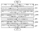
  • step S01 the robot structure data 81, the camera structure data 82, and the sensor structure data 83 are stored in the structure data storage unit 32.
  • step S02 the right camera 2R and the left camera 2L are calibrated by shooting a test pattern.
  • a test pattern is, for example, a pattern in which points of a predetermined size and shape are arranged at predetermined intervals.
  • the test pattern is placed at a predetermined distance in front of the camera to be calibrated, which is the right camera 2R or the left camera 2L, and the camera to be calibrated captures the test pattern. Calibrate the camera to be calibrated so that the image to be captured is correct.
  • the object of calibration is lens aberration and the like.
  • the test pattern is photographed simultaneously with the right camera 2R and the left camera 2L. Adjust the distance between the two cameras and the installation angle so that the images captured by the right camera 2R and the left camera 2L have an appropriate relationship.
  • the procedure of individually photographing the test pattern with the right camera 2R and the left camera 2L may be omitted.
  • a correction parameter for matching the distance measured by the right camera 2R and the left camera 2L with the actual distance is obtained.
  • the robot 1 is made to take a posture for calibration, an object of a predetermined length (called a ruler object) is placed at a position of a predetermined distance from the right camera 2R and the left camera 2L, and a ruler object is photographed. .. Measure the distance from the captured image to the ruler object and the length of the ruler object. Take a picture of a ruler object at several distances and measure it. Find the conversion factor to multiply and the offset value to add so that the measured distance and length match the actual distance and length. The conversion factor and the offset value are the correction parameters.
  • step S04 the peripheral point cloud data 68, which is a three-dimensional model of the object 20 and its surrounding environment, is first generated.
  • the first generation is called the initial generation.
  • the operation in S04 will be described with reference to the flowchart shown in FIG.
  • step S05 the robot 1 is moved to a position where the object 20 is gripped.
  • step S06 the humanoid portion 1H is moved while photographing the object 20 and its surroundings, and the object 20 is gripped by one of the hand portions 11E.
  • the operation in S06 will be described with reference to the flowchart shown in FIG.
  • step S07 the robot 1 is moved while the object 20 is gripped by one of the hand portions 11E. After moving, the hand portion 11E is operated to release the object 20. It is not necessary to omit S04 and initially generate the peripheral point cloud data 68. In that case, when the robot 1 handles the object 20, the peripheral point cloud data 68 is generated.
  • peripheral point cloud data 68 which is a three-dimensional model of the surrounding environment including the object 20, will be described.
  • the robot 1 is moved near the object 20.
  • the position sensor 91 measures the vehicle posture 56.
  • the posture sensor 92 measures the posture data 57 and generates a robot three-dimensional model 64 including the camera posture 65 based on the vehicle posture 56 and the posture data 57.
  • the right camera 2R and the left camera 2L capture an image including the object 20, extract feature points from the captured image, and generate camera point cluster data 66.
  • the camera point cloud data 66 and the camera posture 65 are used to generate the camera point cloud data 67, and the peripheral point cloud data 68 is generated or modified.
  • step S15 it is checked whether the peripheral point cloud data 68 can be generated with a necessary and sufficient range and accuracy. If the peripheral point cloud data 68 can be generated with a necessary and sufficient range and accuracy (YES in S15), the process ends.
  • step S31 the posture sensor 92 measures the posture data 57.
  • step S32 the robot three-dimensional model 64 including the camera posture 65 is generated from the vehicle posture 56 and the posture data 57.
  • step S33 the right camera 2R and the left camera 2L take an image of the object 20.
  • step S34 the stereoscopic display device 4 displays the 3D image 52 in stereoscopic view.
  • step S35 it is checked whether the object 20 is present in the fields of view of both the right camera 2R and the left camera 2L.
  • the camera point cloud data 67 is generated from the captured image in step S36.
  • step S37 it is checked whether the camera point cloud data 67 can be generated. If the camera point cloud data 67 can be generated (YES in S37), the peripheral point cloud data 68 is corrected by the camera point cloud data 67 in step S38.
  • step S39 the peripheral point cloud data 68 and the robot three-dimensional model 64 are integrated to generate an integrated three-dimensional model 69.
  • the model image 53 is generated from the integrated three-dimensional model 69.
  • the display device 5 displays the model image 53.
  • the process proceeds to S39. .. In this case, in S39, the stored peripheral point cloud data 68 is used.
  • step S42 the operator 30 sees the 3D image 52 stereoscopically displayed on the stereoscopic display device 4 or the model image 53 displayed on the display device 5.
  • step S43 the operator 30 moves the humanoid unit 1H. In this way, the operator 30 operates the humanoid unit 1H while confirming the relative positional relationship between the object 20 and the hand unit 11E of the robot 1.
  • step S44 it is checked whether the output (tactile data 60) of the pressure sensor 95 of the hand unit 11E is in contact.
  • the fact that the output of the pressure sensor 95 is in contact means that the hand portion 11E is in contact with the object. If the output of the pressure sensor 95 is in contact (YES in S44), the process ends. After that, based on the output of the pressure sensor 95, the hand unit 11E is controlled to appropriately grip the object 20. If the output of the pressure sensor 95 is not in contact (NO in S44), it is checked in step S45 whether the determined control cycle Tc has elapsed. If Tc has elapsed (YES in S45), the process returns to S31. If Tc has not elapsed (NO in S45), the process returns to S33.
  • the operator 30 can freely switch between the stereoscopically displayed 3D image 52 and the model image 53 by moving his / her head.
  • the model image 53 is an image of viewing the robot 1 and the object 20 from the viewpoint designated by the operator 30.
  • the remote control manipulator system 100 measures the positional relationship between the object 20 and the hand unit 11E, and displays a model image 53 showing the measured positional relationship.
  • the operator 30 confirms an image that is the appropriate one of the 3D image 52 and the model image 53, or both images. Based on the confirmation result, the current state of the humanoid unit 1H including the hand unit 11E is grasped, and the humanoid unit 1H is remotely controlled.
  • the operator 30 repeats the operation of confirming the current state and moving the humanoid unit 1H until the object 20 and the hand unit 11E come into contact with each other. By doing so, the operator 30 can remotely control the robot 1 to perform operations such as pushing, pulling, and gripping the object more accurately and easily than before.
  • the model image 53 can be viewed from any viewpoint. Further, the model images 53 viewed from a plurality of different viewpoints are displayed on the display device 5 at the same time or by switching, and the operator 30 can grasp the object 20 and the surrounding environment from the plurality of different viewpoints. For example, two model images 53 are displayed simultaneously on the display device 5, one image displays the model image 53 from the same viewpoint, and the other images are displayed by switching the model image 53 viewed from a plurality of viewpoints. You may let me. The operator can confirm the control reference information expressed by images, characters, symbols, and the like. As a result, the operator 30 can grasp the relative positional relationship between the robot 1 and the object 20 more accurately and easily than in the conventional case.
  • the operator 30 can accurately grasp the current positional relationship between the robot 1 and the object 20, and it is possible to perform precise operations. It becomes.
  • the positional relationship between the robot 1 and the object 20 for example, when the arm portion 11J of the robot 1 hides the object 20, when there is an obstacle between the robot 1 and the object 20, the head 11F
  • the hand portion 11E is in a position where the hand portion 11E does not reach the object 20 in the posture toward the object 20.
  • the operator 30 can see the natural 3D image 52, and can operate the robot while confirming the current posture of the robot 1 and the relationship between the object 20 and its surrounding environment. Therefore, the operator 30 can perform the work of handling the object 20 more precisely and accurately.
  • the manipulator remote control system is expected to be used for gripping with a remote work machine or a robot's hand while viewing an image from a remote location at the time of disaster relief or at a factory or construction site in a general industry.
  • a remote work machine or a robot's hand while viewing an image from a remote location at the time of disaster relief or at a factory or construction site in a general industry.
  • the visual-based operation system of the remote control manipulator of the present disclosure it is expected that the operator can judge the surrounding environment and the work situation from the visual-based information, and the operation reliability of the remote control manipulator can be improved.
  • the ranging rider 16L is provided on the front side portion of the left forearm portion 11D near the wrist joint portion 12C.
  • the ranging lidars 16R and 16L are mounted on the forearm portion 11D so as to radiate a laser beam inside the forearm portion 11D.
  • the inside of the forearm portion 11D is the side where the forearm portion 11D in the reference state faces the center line of the robot 1A.
  • the center line of the robot 1A extends in the height direction when the robot 1A in the reference state is viewed from the front.
  • the ranging rider 16B is provided so as to radiate to the front side of the body portion 11A.
  • the humanoid unit may have only one of the distance measuring lidar 16R.
  • the discontinuity extraction unit 47 takes in the rider point cluster data 72, processes the rider point cluster data 72, and extracts the discontinuity.
  • the rider coordinate conversion unit 48 converts the rider point cloud data 72 into the rider point cloud data 74, which is the position data in the field coordinate system, with reference to the rider posture 73.
  • the rider point cloud matching unit 49 generates the rider peripheral point cloud data 75.
  • the rider peripheral point cloud data 75 is data expressing the direction and distance to each object existing as the surrounding environment.
  • the rider point cloud matching unit 49 generates the rider peripheral point cloud data 75 by connecting the rider point cloud data 74 in different rider postures 73 so that the positions of the discontinuous points match or the difference in position becomes small.
  • the different rider posture 73 means that at least one of the positions and postures of at least one ranging rider 16 is different.
  • the average of the rider point cloud data 74 in the same rider posture 73 is taken as the rider point cloud data 74, and the rider point cloud data 74 in one rider posture 73 is connected to the rider point cloud data 74 in another rider posture 73.
  • the lidar peripheral point cloud data 75 may be generated.
  • the rider peripheral point cloud data 75 is distance measurement data including the distance and direction to the surrounding environment.
  • the distance measuring lidars 16R, 16L, and 16B are distance measuring sensors that measure distance measuring data.
  • the rider peripheral point cloud data 75 is a sensor ambient environment model.
  • the sensor ambient environment model is an ambient environment model generated from ranging data.
  • the environment model generation unit 35A is a distance measurement data processing model generation unit that processes distance measurement data based on the position and distance measurement direction of the distance measurement sensor to generate a sensor surrounding environment model.
  • step S14A the right camera 2R and the left camera 2L take an image including the object 20, and the camera peripheral point cloud data 71 is generated or modified from the taken image.
  • step S15A it is checked whether the camera peripheral point cloud data 71 can be generated with a necessary and sufficient range and accuracy.
  • S14A and S15A are different from S14 and S15 in that the camera peripheral point cloud data 71 is processed instead of the peripheral point cloud data 68.
  • the lidar peripheral point cloud data 75 could not be generated with the necessary and sufficient range and accuracy (NO in S20), check whether to take a different posture in step S21.
  • the humanoid portion 1HA is made to take a different posture in step S22.
  • step S48 the rider point cloud data 74 modifies the rider peripheral point cloud data 75 in step S49.
  • step S50 the display state is set to be unusable for the camera, and the lidar peripheral point cloud data 75 is selected as the peripheral point cloud data 68. Then, proceed to S39.
  • step S55 the attitude sensor 92 measures the attitude data 57 in step S55.
  • step S56 the robot three-dimensional model 64A including the camera posture 65 and the rider posture 73 is generated from the vehicle posture 56 and the posture data 57.
  • step S57 the right camera 2R and the left camera 2L take an image of the object 20.
  • the operator 30 can freely switch between the stereoscopically displayed 3D image 52 and the model image 53 for viewing.
  • the model image 53 is an image of viewing the robot 1 and the object 20 from the viewpoint designated by the operator 30.
  • the operator 30 can remotely control the robot 1A to perform operations such as pushing, pulling, and grasping the object 20 more accurately and easily than before.
  • the remote control manipulator system 100A operates in the same manner as the remote control manipulator system 100, and the same effect can be obtained.
  • Both the camera peripheral point cloud data 71 and the rider peripheral point cloud data 75 may be selected as the peripheral point cloud data to generate an integrated 3D model. Both the camera peripheral point cloud data 71 and the rider peripheral point cloud data 75 are displayed in the model image generated based on the integrated 3D model. When both are displayed, the display color of the image is changed between the camera peripheral point cloud data 71 and the rider peripheral point cloud data 75, and both images are transparent. By making it a transparent image, both images of the lidar peripheral point cloud data 75 of the camera peripheral point cloud data 71 can be seen, and the robot 1A behind the lidar peripheral point cloud data 75 of the camera peripheral point cloud data 71 and the like. You can also see the surrounding environment.
  • the operator 30 may be able to input an instruction for selecting whether to display.
  • the operator 30 may be able to change the display method after starting the process of handling the object 20.
  • a distance measuring sensor that measures the distance to a surrounding object by radiating radio waves or ultrasonic waves may be used. Any range-finding sensor may be used as long as it can measure the distance to an object in each direction with a necessary and sufficient scan angle range and angle resolution. The above also applies to other embodiments.
  • the robot 3D model 64A is currently referred to as the 3D model 64A, and the robot 3D model 64B is referred to as the target 3D model 64B.
  • the target three-dimensional model 64B is a three-dimensional model in which the robot 1A takes the target posture 54 input by the operator 30.
  • the target three-dimensional model 64B is a target manipulator model that is a manipulator model after the robot 1A executes an operation according to an operation instruction.
  • the model image 53B is an image of the robot 1A taking the target posture 54 viewed from a designated viewpoint.
  • the camera coordinate conversion unit 45 converts the camera point cloud data 66 into the camera point cloud data 67 based on the camera posture 65 currently included in the 3D model 64A.
  • the rider coordinate conversion unit 48 converts the rider point cloud data 72 into the rider point cloud data 74 based on the rider posture 73 currently included in the three-dimensional model 64A.
  • the integrated 3D model 69B is data representing a 3D model in which the target 3D model 64B and the surrounding point cloud data 68 representing the current surrounding environment are integrated.
  • the state data storage unit 33B does not currently store the integrated 3D model that integrates the 3D model 64A and the peripheral point cloud data 68.
  • the model image 53B is an image of the integrated three-dimensional model 69B viewed from the viewpoint specified by the viewpoint data 70.
  • the model image 53B is displayed on the display device 5.
  • the model integration unit 36B integrates the target 3D model 64B and the peripheral point cloud data 68 to generate an integrated 3D model 69B.
  • the model image generation unit 38B generates the model image 53B using the integrated 3D model 69B.
  • the robot model generation unit 34B Since the model image 53B is not presented to the operator 30 when the peripheral point cloud data 68 is initially generated, S04A is not changed. When the model image 53B is presented when the peripheral point cloud data 68 is initially generated, S04A is changed.
  • the flowchart for explaining the procedure for initially generating the peripheral point cloud data 68 shown in FIG. 15 is modified as follows.
  • the robot model generation unit 34B In S13A and S25, the robot model generation unit 34B generates the current 3D model 64A and the target 3D model 64B including the rider posture 73 and the camera posture 65. S13A or S25 As the next procedure, a procedure for displaying the model image 53B on the display device 5 is added.

Abstract

In head-mounted display devices that enable stereoscopic viewing, easily switching views between an image viewed stereoscopically and a model image based on a three-dimensional model is difficult. The present invention comprises: a manipulator 1 that is subjected to remote control 20 by an operator 30 and that handles an object; a stereoscopic viewing display device 4 that displays a right-eye image 51R and a left-eye image 51L captured by a right camera 2R and a left camera 2L, which are installed on the manipulator 1, such that the images can be viewed stereoscopically; a model image generation unit 38 that generates a model image 53, which is generated through image processing of the right-eye image 51R and the left-eye image 51L and in which an integrated three-dimensional model 69 is viewed from a viewpoint designated by the operator, the integrated three-dimensional model 69 being obtained by integrating a manipulator model 64 and a surrounding-environment model 68, which is a three-dimensional model of an object 20 and the environment surrounding the object 20; and a model image display device 5 that displays the model image 53 and that enables the operator 30 to switch views between the model image display device 5 and the stereoscopic viewing display device 4 through head movement.

Description

遠隔制御マニピュレータシステムおよび遠隔制御支援システムRemote control manipulator system and remote control support system
 本開示は、マニピュレータを遠隔制御する遠隔制御マニピュレータシステムおよびマニピュレータを遠隔制御することを支援する遠隔制御支援システムに関する。 The present disclosure relates to a remote control manipulator system that remotely controls a manipulator and a remote control support system that supports remote control of a manipulator.
 マニピュレータやロボットなどを遠隔操作することを支援する遠隔操作支援装置が提案されている(特許文献1参照)。遠隔操作支援装置は、ロボットが扱う対象物の3次元モデルおよびロボットの3次元モデルを生成し、3次元空間の指定された視点から見たロボットおよび対象物が表示された画像を生成して、操作者に提示する。対象物の3次元モデルは、レーザスキャナ13にて計測された対象物11上の点群データから生成する。ロボットの3次元モデルは、ロボット12の各軸の状態19に基づいてロボット12の動作状態を反映させて生成する。 A remote control support device that supports remote control of manipulators, robots, etc. has been proposed (see Patent Document 1). The remote control support device generates a three-dimensional model of the object handled by the robot and a three-dimensional model of the robot, and generates an image showing the robot and the object viewed from a specified viewpoint in the three-dimensional space. Present to the operator. The three-dimensional model of the object is generated from the point cloud data on the object 11 measured by the laser scanner 13. The three-dimensional model of the robot is generated by reflecting the operating state of the robot 12 based on the state 19 of each axis of the robot 12.
 ロボットやマニピュレータを遠隔制御するために、オペレータが頭に両目を覆うように装着する表示装置であるヘッドマウントディスプレイ(Head Mount Display、HMD)を装着するシステムがある(特許文献2参照)。 In order to remotely control a robot or manipulator, there is a system in which a head-mounted display (HMD), which is a display device worn by an operator so as to cover both eyes on the head, is mounted (see Patent Document 2).
特開2009-006410JP 2009-006410 WO2019/059364WO2019 / 059364
 ロボットにはカメラや各種センサが搭載される。カメラが撮影した画像や各種センサが検出したセンサ情報は、ディスプレイに表示される。オペレータは、ディスプレイに表示された画像やセンサ情報を確認しながらロボットを操作する。遠近も認識できる立体視画像(3D画像とも呼ぶ)をオペレータが容易に見ることができるように、オペレータはHMDを装着する。オペレータがHMDを頭部に装着する場合には、オペレータが見ることができる情報がHMDを介して提供される情報に限定されるという課題がある。 The robot is equipped with a camera and various sensors. Images taken by the camera and sensor information detected by various sensors are displayed on the display. The operator operates the robot while checking the image and sensor information displayed on the display. The operator wears an HMD so that the operator can easily see a stereoscopic image (also called a 3D image) that can recognize perspective. When the operator wears the HMD on the head, there is a problem that the information that the operator can see is limited to the information provided via the HMD.
 例えば、ロボットに搭載されたカメラの視野の画像(以下、ロボット視野画像と呼ぶ)を立体視させる場合に、オペレータがHMDを装着する場合には、以下のような課題がある。オペレータの顔の向きによらず常にロボット視野画像を表示すると、ロボット視野画像以外の情報(ロボットの位置情報や姿勢情報、周囲の環境情報など、制御参考情報と呼ぶ)を、オペレータが確認することが難しい。HMDに3D画像と制御参考情報を重畳して提供する場合には、制御参考情報の表示サイズや情報量が限定され、3D画像とそれ以外の情報が重畳されているために画像が見づらい。 For example, when the image of the field of view of the camera mounted on the robot (hereinafter referred to as the robot field of view image) is stereoscopically viewed, when the operator wears the HMD, there are the following problems. When the robot field image is always displayed regardless of the orientation of the operator's face, the operator confirms information other than the robot field image (called control reference information such as robot position information, posture information, and surrounding environment information). Is difficult. When the 3D image and the control reference information are superimposed and provided on the HMD, the display size and the amount of information of the control reference information are limited, and the image is difficult to see because the 3D image and other information are superimposed.
 制御参考情報として、カメラの視点とは異なる視点から見た対象物およびロボットの画像である別視点画像をHMDに表示する場合を考える。HMDにロボット視野画像または別視点画像の何れを表示するかを、オペレータが入力する必要があり、オペレータに負担になる。表示システムとしても、オペレータが入力する表示画像の切替指示に対応できる必要があり、システムが複雑になる。 As control reference information, consider a case where an object viewed from a viewpoint different from the viewpoint of the camera and another viewpoint image, which is an image of the robot, are displayed on the HMD. It is necessary for the operator to input whether to display the robot visual field image or the different viewpoint image on the HMD, which is a burden on the operator. The display system also needs to be able to respond to the switching instruction of the display image input by the operator, which complicates the system.
 本開示は、マニピュレータが扱う物体を立体的に見る立体視画像と、任意の視点から周囲環境およびマニピュレータを見るモデル画像とを操作者が頭を移動させることで容易に切り替えて見ることができる遠隔制御マニピュレータシステムおよび遠隔制御支援システムを得ることを目的とする。周囲環境とは、マニピュレータが扱う物体および物体の周囲の事物である。 The present disclosure allows the operator to easily switch between a stereoscopic image of an object handled by the manipulator and a model image of the surrounding environment and the manipulator from an arbitrary viewpoint by moving the head. The purpose is to obtain a control manipulator system and a remote control support system. The surrounding environment is the object handled by the manipulator and the things around the object.
 本開示に係る遠隔制御マニピュレータシステムは、操作者により遠隔制御されて物体を扱うマニピュレータと、マニピュレータが動くまたは静止する動作を指示する動作指示を操作者が入力する動作指示入力部と、動作指示からマニピュレータを制御する制御信号を生成する制御信号生成部と、決められた位置関係を有してマニピュレータに搭載された右カメラおよび左カメラと、右カメラが撮影する右目画像および左カメラが撮影する左目画像を立体的に見えるように表示する立体視表示装置と、マニピュレータの位置および姿勢を表す位置姿勢情報を検出する位置姿勢センサと、マニピュレータの構造を表すマニピュレータ構造データ、および右カメラおよび左カメラの構造を表すカメラ構造データを記憶する構造データ記憶部と、マニピュレータ構造データ、カメラ構造データおよび位置姿勢情報を参照して、右カメラおよび左カメラを含むマニピュレータの3次元モデルであるマニピュレータモデルを生成するマニピュレータモデル生成部と、マニピュレータモデルに含まれる右カメラおよび左カメラの位置と撮影方向に基づき、右目画像および左目画像を画像処理して、物体および物体の周囲の事物である周囲環境の3次元モデルである周囲環境モデルを生成する画像処理モデル生成部と、周囲環境モデルとマニピュレータモデルを統合した3次元モデルである統合3次元モデルを生成するモデル統合部と、操作者が指定した視点から統合3次元モデルを見る画像であるモデル画像を生成するモデル画像生成部と、モデル画像を表示する、操作者が頭を移動させることで立体視表示装置と切り替えて見ることができるモデル画像表示装置とを備えたものである。 The remote control manipulator system according to the present disclosure is composed of a manipulator that is remotely controlled by an operator to handle an object, an operation instruction input unit in which an operator inputs an operation instruction instructing an operation in which the manipulator moves or stands still, and an operation instruction. A control signal generator that generates a control signal that controls the manipulator, a right camera and a left camera mounted on the manipulator with a fixed positional relationship, and a right eye image taken by the right camera and a left eye taken by the left camera. A stereoscopic display device that displays an image in a three-dimensional manner, a position / orientation sensor that detects position / orientation information indicating the position and orientation of the manipulator, manipulator structure data representing the structure of the manipulator, and right and left cameras. A manipulator model, which is a three-dimensional model of a manipulator including a right camera and a left camera, is generated by referring to a structure data storage unit that stores camera structure data representing a structure and manipulator structure data, camera structure data, and position / orientation information. Based on the position and shooting direction of the manipulator model generator and the right and left cameras included in the manipulator model, the right-eye image and the left-eye image are image-processed to create a three-dimensional model of the object and the surrounding environment of the object. The image processing model generator that generates the ambient environment model, the model integration unit that generates the integrated 3D model that is a 3D model that integrates the ambient environment model and the manipulator model, and the integration 3 from the viewpoint specified by the operator. A model image generation unit that generates a model image that is an image for viewing a three-dimensional model, and a model image display device that displays a model image and can be switched between a stereoscopic display device and a stereoscopic display device by the operator moving his / her head. It is prepared.
 本開示に係る遠隔制御支援システムは、操作者により遠隔制御されて物体を扱うマニピュレータに搭載されて決められた位置関係を有する右カメラおよび左カメラが撮影する右目画像および左目画像を立体的に見えるように表示する立体視表示装置と、マニピュレータの構造を表すマニピュレータ構造データ、および右カメラおよび左カメラの構造を表すカメラ構造データを記憶する構造データ記憶部と、マニピュレータ構造データ、カメラ構造データおよびマニピュレータの位置および姿勢を表す位置姿勢情報を参照して、右カメラおよび左カメラを含むマニピュレータの3次元モデルであるマニピュレータモデルを生成するマニピュレータモデル生成部と、マニピュレータモデルに含まれる右カメラおよび左カメラの位置と撮影方向に基づき、右目画像および左目画像を画像処理して、物体および物体の周囲の事物である周囲環境の3次元モデルである周囲環境モデルを生成する画像処理モデル生成部と、周囲環境モデルとマニピュレータモデルを統合した3次元モデルである統合3次元モデルを生成するモデル統合部と、操作者が指定した視点から統合3次元モデルを見る画像であるモデル画像を生成するモデル画像生成部と、モデル画像を表示する、操作者が頭を移動させることで立体視表示装置と切り替えて見ることができるモデル画像表示装置とを備えたものである。 The remote control support system according to the present disclosure is mounted on a manipulator that is remotely controlled by an operator and handles an object, and can see three-dimensionally the right-eye image and the left-eye image taken by the right camera and the left camera having a determined positional relationship. A three-dimensional display device that displays the image, a manipulator structure data that represents the structure of the manipulator, and a structure data storage unit that stores the camera structure data that represents the structure of the right camera and the left camera, and the manipulator structure data, camera structure data, and manipulator. A manipulator model generator that generates a manipulator model that is a three-dimensional model of a manipulator including a right camera and a left camera, and a right camera and a left camera included in the manipulator model, with reference to the position and orientation information that represents the position and orientation of An image processing model generator that processes the right-eye image and the left-eye image based on the position and shooting direction to generate a surrounding environment model that is a three-dimensional model of the surrounding environment that is an object and things around the object, and the surrounding environment. A model integration unit that generates an integrated 3D model that is a 3D model that integrates a model and a manipulator model, and a model image generation unit that generates a model image that is an image of viewing the integrated 3D model from a viewpoint specified by the operator. It is equipped with a model image display device that displays a model image and that can be switched between a stereoscopic display device and a viewing device by the operator moving his / her head.
 本開示によれば、マニピュレータが扱う物体を立体的に見る立体視画像と、任意の視点から物体および物体の周囲の事物である周囲環境およびマニピュレータを見るモデル画像とを操作者が頭を移動させることで容易に切り替えて見ることができる。 According to the present disclosure, the operator moves his / her head between a stereoscopic image of an object handled by the manipulator and a model image of the object and the surrounding environment of the object and the manipulator from an arbitrary viewpoint. It can be easily switched and viewed.
実施の形態1に係る遠隔制御マニピュレータシステムの概略構成を説明する図である。It is a figure explaining the schematic structure of the remote control manipulator system which concerns on Embodiment 1. FIG. 実施の形態1に係る遠隔制御マニピュレータシステムの機能構成を示すブロック図である。It is a block diagram which shows the functional structure of the remote control manipulator system which concerns on Embodiment 1. FIG. 実施の形態1に係る遠隔制御マニピュレータシステムで使用されるロボットの斜視図である。It is a perspective view of the robot used in the remote control manipulator system which concerns on Embodiment 1. FIG. 実施の形態1に係る遠隔制御マニピュレータシステムで使用されるロボットのヒューマノイド部の正面図である。It is a front view of the humanoid part of the robot used in the remote control manipulator system which concerns on Embodiment 1. FIG. 実施の形態1に係る遠隔制御マニピュレータシステムで使用されるロボットのヒューマノイド部の左側面図である。It is a left side view of the humanoid part of the robot used in the remote control manipulator system which concerns on Embodiment 1. FIG. 実施の形態1に係る遠隔制御マニピュレータシステムで使用されるロボットが有する回転軸を説明する図である。It is a figure explaining the rotation axis which the robot used in the remote control manipulator system which concerns on Embodiment 1 has. 実施の形態1に係る遠隔制御マニピュレータシステムで使用されるロボットの腕部が有する回転軸を説明する図である。It is a figure explaining the rotation axis which the arm part of the robot used in the remote control manipulator system which concerns on Embodiment 1 has. 実施の形態1に係る遠隔制御マニピュレータシステムでロボットを遠隔制御する手順を説明するフローチャートである。It is a flowchart explaining the procedure which remotely controls a robot by the remote control manipulator system which concerns on Embodiment 1. 実施の形態1に係る遠隔制御マニピュレータシステムで周囲点群データを初期生成する手順を説明するフローチャートである。It is a flowchart explaining the procedure of initial generation of the peripheral point cloud data in the remote control manipulator system which concerns on Embodiment 1. FIG. 実施の形態1に係る遠隔制御マニピュレータシステムでロボットが物体を把持する際に遠隔制御する手順を説明するフローチャートである。It is a flowchart explaining the procedure of remote control when a robot grips an object in the remote control manipulator system which concerns on Embodiment 1. FIG. 実施の形態2に係る遠隔制御マニピュレータシステムで使用されるロボットのヒューマノイド部の正面図である。It is a front view of the humanoid part of the robot used in the remote control manipulator system which concerns on Embodiment 2. FIG. 実施の形態2に係る遠隔制御マニピュレータシステムで使用されるロボットのヒューマノイド部の左側面図である。It is a left side view of the humanoid part of the robot used in the remote control manipulator system which concerns on Embodiment 2. FIG. 実施の形態2に係る遠隔制御マニピュレータシステムの機能構成を示すブロック図である。It is a block diagram which shows the functional structure of the remote control manipulator system which concerns on Embodiment 2. FIG. 実施の形態2に係る遠隔制御マニピュレータシステムでロボットを遠隔制御する手順を説明するフローチャートである。It is a flowchart explaining the procedure which remotely controls a robot by the remote control manipulator system which concerns on Embodiment 2. 実施の形態2に係る遠隔制御マニピュレータシステムで周囲点群データを初期生成する手順を説明するフローチャートである。It is a flowchart explaining the procedure of initial generation of the peripheral point cloud data in the remote control manipulator system which concerns on Embodiment 2. 実施の形態2に係る遠隔制御マニピュレータシステムでロボットが物体を把持する際に遠隔制御する手順の前半を説明するフローチャートである。It is a flowchart explaining the first half of the procedure of remote control when a robot grips an object in the remote control manipulator system which concerns on Embodiment 2. 実施の形態2に係る遠隔制御マニピュレータシステムでロボットが物体を把持する際に遠隔制御する手順の後半を説明するフローチャートである。It is a flowchart explaining the latter half of the procedure of remote control when a robot grips an object in the remote control manipulator system which concerns on Embodiment 2. 実施の形態3に係る遠隔制御マニピュレータシステムの機能構成を示すブロック図である。It is a block diagram which shows the functional structure of the remote control manipulator system which concerns on Embodiment 3. FIG. 実施の形態3に係る遠隔制御マニピュレータシステムでロボットを遠隔制御する手順を説明するフローチャートである。It is a flowchart explaining the procedure which remotely controls a robot by the remote control manipulator system which concerns on Embodiment 3. 実施の形態3に係る遠隔制御マニピュレータシステムでロボットが物体を把持する際に遠隔制御する手順の前半を説明するフローチャートである。It is a flowchart explaining the first half of the procedure of remote control when a robot grips an object in the remote control manipulator system which concerns on Embodiment 3. 実施の形態3に係る遠隔制御マニピュレータシステムでロボットが物体を把持する際に遠隔制御する手順の後半を説明するフローチャートである。It is a flowchart explaining the latter half of the procedure of remote control when a robot grips an object in the remote control manipulator system which concerns on Embodiment 3. FIG. 実施の形態4に係る遠隔制御マニピュレータシステムおよび遠隔制御支援システムの機能構成を示すブロック図である。It is a block diagram which shows the functional structure of the remote control manipulator system and the remote control support system which concerns on Embodiment 4. FIG.
 実施の形態1.
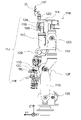
 図1および図2を参照して、遠隔制御マニピュレータシステム100の概略構成を説明する。図1は、実施の形態1に係る遠隔制御マニピュレータシステムの概略構成を説明する図である。図2は、実施の形態1に係る遠隔制御マニピュレータシステムの機能構成を示すブロック図である。遠隔制御マニピュレータシステム100は、クローラ移動ロボット1(ロボット1と略す)、右カメラ2R、左カメラ2L、制御装置3、立体視表示装置4、表示装置5、目標姿勢入力装置6を主に有して構成される。ロボット1は、オペレータ30により遠隔制御されて物体20を扱うマニピュレータである。ロボット1が物体20を扱う場所を現場と呼ぶ。オペレータ30が居る場所を指令所と呼ぶ。オペレータ30は、マニピュレータを遠隔制御する操作者である。
Embodiment 1.
A schematic configuration of the remote control manipulator system 100 will be described with reference to FIGS. 1 and 2. FIG. 1 is a diagram illustrating a schematic configuration of a remote control manipulator system according to the first embodiment. FIG. 2 is a block diagram showing a functional configuration of the remote control manipulator system according to the first embodiment. The remote control manipulator system 100 mainly includes a crawler mobile robot 1 (abbreviated as robot 1), a right camera 2R, a left camera 2L, a control device 3, a stereoscopic display device 4, a display device 5, and a target attitude input device 6. It is composed of. The robot 1 is a manipulator that is remotely controlled by the operator 30 and handles the object 20. The place where the robot 1 handles the object 20 is called a site. The place where the operator 30 is located is called a command center. The operator 30 is an operator who remotely controls the manipulator.
 右カメラ2Rおよび左カメラ2Lは、ロボット1の頭部に搭載されて画像を撮影する。制御装置3は、ロボット1を制御する。立体視表示装置4は、右カメラ2Rおよび左カメラ2Lで撮影された画像を立体視表示する。立体視表示するとは、立体的に見えるように表示することである。表示装置5は、ロボット1および周囲環境の3次元モデルを任意の視点から見る画像や、ロボット1を制御する上で必要あるいは有用な情報を表示する。周囲環境は、物体20および物体20の周囲の事物である。周囲環境の3次元モデルが、周囲環境モデルである。目標姿勢入力装置6は、オペレータ30がロボット1を操作する際に、操作後の目標となる位置および姿勢を表す目標姿勢を入力する。目標姿勢は、ロボット1が動くまたは静止する動作をオペレータ30が指示する動作指示である。目標姿勢は、動作指示に従う動作を実行後のロボット1の位置および姿勢を表す。目標姿勢目標姿勢入力装置6は、動作指示をオペレータ30が入力する動作指示入力部である。 The right camera 2R and the left camera 2L are mounted on the head of the robot 1 and take an image. The control device 3 controls the robot 1. The stereoscopic display device 4 displays the images taken by the right camera 2R and the left camera 2L in stereoscopic view. Stereoscopic display is to display so that it looks three-dimensional. The display device 5 displays an image of the robot 1 and the three-dimensional model of the surrounding environment viewed from an arbitrary viewpoint, and information necessary or useful for controlling the robot 1. The surrounding environment is the object 20 and the things around the object 20. The three-dimensional model of the surrounding environment is the surrounding environment model. When the operator 30 operates the robot 1, the target posture input device 6 inputs a target posture representing a target position and posture after the operation. The target posture is an operation instruction in which the operator 30 instructs an operation in which the robot 1 moves or stands still. The target posture represents the position and posture of the robot 1 after executing the movement according to the movement instruction. Target posture The target posture input device 6 is an operation instruction input unit in which the operator 30 inputs an operation instruction.
 遠隔制御の対象であるロボットは、図3から図5に示すロボット1である。遠隔制御マニピュレータシステムは、ロボット1とは異なるロボットも遠隔制御することができる。図3は、実施の形態1に係る遠隔制御マニピュレータシステムで使用されるロボットの斜視図である。図4は、実施の形態1に係る遠隔制御マニピュレータシステムで使用されるロボットのヒューマノイド部を拡大した正面図である。図5は、ヒューマノイド部の左側面図である。ロボット1は、車両部1Wと、ヒューマノイド部1Hと、制御部7とを有する。車両部1Wは、クローラ(キャタピラ)を車輪で回転させて移動する車両である。ヒューマノイド部1Hは、車両部1Wの前方上面に搭載される。ヒューマノイド部1Hは、2本の腕部、胴体部および頭部を有する。制御部7は、車両部1Wおよびヒューマノイド部1Hを制御する。図3から図5に示す姿勢をロボット1がとる状態を、ロボット1の基準状態と呼ぶ。 The robot targeted for remote control is the robot 1 shown in FIGS. 3 to 5. The remote control manipulator system can also remotely control a robot different from the robot 1. FIG. 3 is a perspective view of a robot used in the remote control manipulator system according to the first embodiment. FIG. 4 is an enlarged front view of the humanoid portion of the robot used in the remote control manipulator system according to the first embodiment. FIG. 5 is a left side view of the humanoid portion. The robot 1 has a vehicle unit 1W, a humanoid unit 1H, and a control unit 7. The vehicle unit 1W is a vehicle that moves by rotating a crawler (caterpillar) with wheels. The humanoid unit 1H is mounted on the front upper surface of the vehicle unit 1W. The humanoid portion 1H has two arms, a body and a head. The control unit 7 controls the vehicle unit 1W and the humanoid unit 1H. The state in which the robot 1 takes the postures shown in FIGS. 3 to 5 is referred to as a reference state of the robot 1.
 XYZ座標系は、ロボット1が存在する空間を表す直交座標系である。XY平面は水平な平面である。XYZ座標系を現場座標系とも呼ぶ。X軸は東西方向に平行で、Y軸は南北方向に平行である。東をX軸の正の向きとし、北をY軸の正の向きとする。Z軸は、高さ方向の軸である。上方をZ軸の正の向きとする。位置センサ91は、車両部1WのXYZ座標系での位置と姿勢を計測する。車両部1Wの位置は、車両部1Wの重心のXYZ座標系での位置である。車両部1Wの姿勢は、車両部1Wの前方が向く方向である。車両部1Wの姿勢は、ヨー角、ピッチ角およびロール角で表現する。車両部1Wの位置および姿勢を表すデータを、車両姿勢56と呼ぶ。 The XYZ coordinate system is a Cartesian coordinate system that represents the space in which the robot 1 exists. The XY plane is a horizontal plane. The XYZ coordinate system is also called the field coordinate system. The X-axis is parallel to the east-west direction and the Y-axis is parallel to the north-south direction. The east is the positive orientation of the X-axis and the north is the positive orientation of the Y-axis. The Z axis is an axis in the height direction. The upper side is the positive direction of the Z axis. The position sensor 91 measures the position and posture of the vehicle unit 1W in the XYZ coordinate system. The position of the vehicle unit 1W is the position of the center of gravity of the vehicle unit 1W in the XYZ coordinate system. The posture of the vehicle unit 1W is a direction in which the front of the vehicle unit 1W faces. The posture of the vehicle unit 1W is expressed by a yaw angle, a pitch angle, and a roll angle. The data representing the position and posture of the vehicle unit 1W is referred to as a vehicle posture 56.
 車両部1Wの姿勢を表現するために、車両部1Wとともに移動する第1の直交座標系(X1Y1Z1座標系)を以下のように定義する。第1の直交座標系は、ヒューマノイド部1Hの車両部1Wに対する姿勢を表現する上でも使用する。車両部1Wの上面をロボット基準面と呼ぶ。
  X1軸:車両部1Wの左右方向に平行な軸。
  Y1軸:車両部1Wの前後方向に平行な軸。
  Z1軸:車両部1Wの高さ方向に平行な軸。
 X1軸、Y1軸、Z1軸は、互いに直交する。右方をX1軸の正の向きとし、前方を1軸の正の向きとし、上方をZ1軸の正の向きとする。X1軸およびY1軸は、ロボット基準面に平行である。車両部1Wの姿勢は、X1軸、Y1軸およびZ1軸がXYZ座標系で向く方向により表現する。Y1軸をXY平面に射影した軸(投影Y1軸)とX軸がなす角度が、ヨー角である。投影Y1軸がXY平面となす角度が、ピッチ角である。投影Y1軸およびZ軸を含む平面とZ1軸とがなす角度が、ロール角である。
In order to express the posture of the vehicle unit 1W, a first orthogonal coordinate system (X1Y1Z1 coordinate system) that moves together with the vehicle unit 1W is defined as follows. The first Cartesian coordinate system is also used to express the posture of the humanoid unit 1H with respect to the vehicle unit 1W. The upper surface of the vehicle unit 1W is called a robot reference surface.
X1 axis: An axis parallel to the left-right direction of the vehicle unit 1W.
Y1 axis: An axis parallel to the front-rear direction of the vehicle unit 1W.
Z1 axis: An axis parallel to the height direction of the vehicle unit 1W.
The X1 axis, the Y1 axis, and the Z1 axis are orthogonal to each other. The right side is the positive direction of the X1 axis, the front is the positive direction of the 1 axis, and the upper side is the positive direction of the Z1 axis. The X1 axis and the Y1 axis are parallel to the robot reference plane. The posture of the vehicle unit 1W is expressed by the direction in which the X1 axis, the Y1 axis, and the Z1 axis face in the XYZ coordinate system. The angle formed by the axis (projected Y1 axis) projected on the XY plane and the X axis is the yaw angle. The angle formed by the projection Y1 axis with the XY plane is the pitch angle. The angle formed by the plane including the projection Y1 axis and the Z axis and the Z1 axis is the roll angle.
 目標姿勢入力装置6は、ヒューマノイド部1Hを制御するための上体目標姿勢入力部6Hと、車両部1Wを制御するための車両姿勢入力部6Wとを有する。上体目標姿勢入力部6Hは、オペレータ30が手を使用してヒューマノイド部1Hに対する目標姿勢を入力する装置である。車両姿勢入力部6Wは、オペレータ30が足を使用して車両部1Wを操縦する装置である。目標姿勢は、ヒューマノイド部1Hを含むロボット1にとらせる姿勢である。目標姿勢は、ロボット1がとる姿勢の目標となる姿勢として入力される。入力された目標姿勢を表すデータを、目標姿勢54と呼ぶ。オペレータ50は、目標姿勢を入力し、入力した目標姿勢を変更できる。 The target posture input device 6 has an upper body target posture input unit 6H for controlling the humanoid unit 1H and a vehicle posture input unit 6W for controlling the vehicle unit 1W. The upper body target posture input unit 6H is a device in which the operator 30 uses his / her hand to input the target posture with respect to the humanoid unit 1H. The vehicle posture input unit 6W is a device in which the operator 30 controls the vehicle unit 1W using his / her feet. The target posture is a posture to be taken by the robot 1 including the humanoid unit 1H. The target posture is input as a target posture of the posture taken by the robot 1. The input data representing the target posture is called the target posture 54. The operator 50 can input the target posture and change the input target posture.
 ヒューマノイド部1Hは、骨格部11が関節部12により回転可能に接続したものである。目標姿勢54は、各関節部12が有する各回転軸の回りの回転角度に対する指令値として表現される。各関節部12が目標姿勢54で指令される角度をとると、ヒューマノイド部1Hは目標姿勢54をとる。長さが変更可能な部分をヒューマノイド部が有する場合には、長さが変更可能な部分の長さに対する指令値も目標姿勢は含む。ヒューマノイド部1Hの構造については、後で説明する。 The humanoid portion 1H is a skeleton portion 11 rotatably connected by a joint portion 12. The target posture 54 is expressed as a command value for a rotation angle around each rotation axis of each joint portion 12. When each joint portion 12 takes an angle commanded by the target posture 54, the humanoid portion 1H takes the target posture 54. When the humanoid portion has a portion whose length can be changed, the target posture also includes a command value for the length of the portion whose length can be changed. The structure of the humanoid part 1H will be described later.
 上体目標姿勢入力部6Hは、各関節部12が有する各回転軸の角度を指定する指令値である目標姿勢54を入力する装置である。上体目標姿勢入力部6Hでは、例えばレバーなどをオペレータ30が操作することで、目標姿勢54を入力する。 The upper body target posture input unit 6H is a device for inputting the target posture 54, which is a command value for designating the angle of each rotation axis of each joint portion 12. In the upper body target posture input unit 6H, for example, the operator 30 operates a lever or the like to input the target posture 54.
 車両姿勢入力部6Wをオペレータ30が足で操作することで、車両部1Wの前進、後進、右回転および左回転の指示を入力する。オペレータ30が入力する指示に応じて車両部1Wが移動する。車両部1Wの位置とヨー角が、オペレータ30が意図するものになると、車両姿勢56の入力が完了する。車両部1Wのピッチ角とロール角は、車両部1Wが有するクローラの下に存在する地面や建築物などの形状により決まる。車両部が、ピッチ角およびロール角の少なくとも一方を変更する機構を備えてもよい。その場合には、車両姿勢入力部により、オペレータ30はピッチ角およびロール角の少なくとも一方を変更する機構に対する指令値も入力する。 The operator 30 operates the vehicle posture input unit 6W with his / her foot to input instructions for forward, reverse, right rotation, and left rotation of the vehicle unit 1W. The vehicle unit 1W moves according to the instruction input by the operator 30. When the position and yaw angle of the vehicle unit 1W are intended by the operator 30, the input of the vehicle posture 56 is completed. The pitch angle and roll angle of the vehicle unit 1W are determined by the shape of the ground or a building existing under the crawler of the vehicle unit 1W. The vehicle unit may be provided with a mechanism for changing at least one of a pitch angle and a roll angle. In that case, the operator 30 also inputs a command value for the mechanism for changing at least one of the pitch angle and the roll angle by the vehicle attitude input unit.
 右カメラ2Rおよび左カメラ2Lは、ロボット1の頭部11Fに搭載される。右カメラ2Rおよび左カメラ2Lは、決められた位置関係を有する。例えば、右カメラ2Rおよび左カメラ2Lは、頭部11Fの正面側の上部の決められた同じ高さの位置に決められた間隔で配置される。右カメラ2Rおよび左カメラ2Lは、ロボット1のハンド部11Eが操作対象である物体20を扱う様子を撮影する。人間が物体20を扱う際に見えるのと同様な画像が撮影できるように、右カメラ2Rおよび左カメラ2Lはロボット1の頭部11Fに搭載する。右カメラ2Rは、右目画像51Rを撮影する。左カメラ2Lは、左目画像51Lを撮影する。右カメラ2Rおよび左カメラ2Lの位置から見える視野を、ロボット視野と呼ぶ。 The right camera 2R and the left camera 2L are mounted on the head 11F of the robot 1. The right camera 2R and the left camera 2L have a predetermined positional relationship. For example, the right camera 2R and the left camera 2L are arranged at a predetermined same height position on the upper part of the front side of the head 11F at a predetermined interval. The right camera 2R and the left camera 2L photograph the state in which the hand portion 11E of the robot 1 handles the object 20 to be operated. The right camera 2R and the left camera 2L are mounted on the head 11F of the robot 1 so that an image similar to that seen when a human handles an object 20 can be taken. The right camera 2R captures the right eye image 51R. The left camera 2L captures the left eye image 51L. The field of view seen from the positions of the right camera 2R and the left camera 2L is called the robot field of view.
 右目画像51Rおよび左目画像51Lは、立体視表示装置4により立体的に見えるように表示される。立体的に見えるように表示することを立体視表示するという。立体視表示される右目画像51Rおよび左目画像51Lを、3D画像52と呼ぶ。立体視表示装置4は、決められた間隔で配置された2個の接眼レンズを有する。オペレータ30は、右目および左目で立体視表示装置4の接眼レンズの中を覗き込むことで立体視表示されている3D画像52を見ることができる。 The right-eye image 51R and the left-eye image 51L are displayed so as to appear stereoscopically by the stereoscopic display device 4. Displaying so that it looks three-dimensional is called stereoscopic display. The right-eye image 51R and the left-eye image 51L that are stereoscopically displayed are referred to as a 3D image 52. The stereoscopic display device 4 has two eyepieces arranged at a predetermined interval. The operator 30 can see the 3D image 52 stereoscopically displayed by looking into the eyepiece of the stereoscopic display device 4 with the right eye and the left eye.
 立体視表示装置4は、右目画像51Rを表示する右目用スクリーンと、左目画像51Lを表示する左目用スクリーンとを有する。物体20および周囲環境との距離や物体20の大きさなどが、オペレータ30が現場にいる場合に見えるものと同様になるように、右目用スクリーンおよび左目用スクリーンの位置および間隔や接眼レンズなどの光学系は設計されている。つまり、立体視表示装置4における輻輳角は、ロボット1に搭載された2台のカメラである右カメラ2Rおよび左カメラ2Lが持つ輻輳角と同じである。立体視表示装置4により、オペレータ30は自然な立体視画像を見ることができる。そのため、オペレータ30は、物体20に対する正確な奥行き感を把握できる。 The stereoscopic display device 4 has a screen for the right eye that displays the right eye image 51R and a screen for the left eye that displays the left eye image 51L. The position and spacing of the right-eye screen and the left-eye screen, the eyepieces, etc., so that the distance between the object 20 and the surrounding environment, the size of the object 20, etc. are the same as those seen when the operator 30 is in the field. The optical system is designed. That is, the convergence angle in the stereoscopic display device 4 is the same as the convergence angle of the right camera 2R and the left camera 2L, which are the two cameras mounted on the robot 1. The stereoscopic display device 4 allows the operator 30 to see a natural stereoscopic image. Therefore, the operator 30 can grasp an accurate sense of depth with respect to the object 20.
 立体視表示装置4は、接眼レンズを有さず、液晶シャッタや偏光眼鏡などを使用するものでもよい。立体視表示装置4は、立体視表示するものであればどのようなものでもよい。 The stereoscopic display device 4 may not have an eyepiece and may use a liquid crystal shutter, polarized glasses, or the like. The stereoscopic display device 4 may be any device as long as it displays stereoscopically.
 表示装置5は、モデル画像53を表示する。モデル画像53は、物体20を含む周囲環境とロボット1の3次元モデルに基づき、ロボット1および周囲環境を任意の視点から見る画像である。モデル画像53の視点は、オペレータ30が入力する情報に基づき決められる。表示装置5には、ロボット1を遠隔制御する上で有用な情報を表示する。ロボット1を遠隔制御する上で有用な情報を、制御参考情報と呼ぶ。表示装置5は、複数個でもよい。 The display device 5 displays the model image 53. The model image 53 is an image of the robot 1 and the surrounding environment viewed from an arbitrary viewpoint based on the three-dimensional model of the surrounding environment including the object 20 and the robot 1. The viewpoint of the model image 53 is determined based on the information input by the operator 30. Information useful for remote control of the robot 1 is displayed on the display device 5. Information useful for remotely controlling the robot 1 is called control reference information. The number of display devices 5 may be plurality.
 図1に示す例では、オペレータ30が椅子に座り、オペレータ30の頭の前方に箱状の立体視表示装置4を設け、立体視表示装置4の右側上方に表示装置5を設けている。立体視表示装置4および表示装置5の配置は、オペレータ30が頭を移動させることで、どちらかの表示装置を選択して見ることができる位置であればどのような配置でもよい。表示装置5は、大きな画面を有するものや、スクリーンにプロジェクタで投影するものでもよい。表示装置5は、オペレータ30が頭を移動させることで立体視表示装置4と切り替えて見ることができるように配置されていればよい。 In the example shown in FIG. 1, the operator 30 sits on a chair, a box-shaped stereoscopic display device 4 is provided in front of the operator 30's head, and a display device 5 is provided on the upper right side of the stereoscopic display device 4. The stereoscopic display device 4 and the display device 5 may be arranged in any position as long as the operator 30 can select and view either display device by moving his / her head. The display device 5 may have a large screen or may be projected onto the screen by a projector. The display device 5 may be arranged so that the operator 30 can switch to and view the stereoscopic display device 4 by moving his / her head.
 オペレータ30は、立体視表示装置4の接眼レンズを覗き込むことで物体20などをロボット視野で立体視できる。オペレータ30は、頭の位置および向きを変化させることで表示装置5にされたモデル画像53を見ることができる。 The operator 30 can see the object 20 and the like stereoscopically in the robot field of view by looking into the eyepiece of the stereoscopic display device 4. The operator 30 can see the model image 53 on the display device 5 by changing the position and orientation of the head.
 制御装置3は、ロボット1を遠隔制御する。制御装置3は、CPU21、メモリ部22などを含む電子計算機により実装される。メモリ部22は、CPU21で実行されるプログラムや処理に使用するデータあるいは処理の結果で得られるデータなどを記憶する。メモリ部22は、フラッシュメモリのような半導体メモリおよびハードディスクである。メモリ部22は、揮発性の記憶装置および不揮発性の記憶装置を含む。制御部7も、CPU23、メモリ部24などを含む電子計算機により実装される。 The control device 3 remotely controls the robot 1. The control device 3 is mounted by an electronic computer including a CPU 21, a memory unit 22, and the like. The memory unit 22 stores programs executed by the CPU 21, data used for processing, data obtained as a result of processing, and the like. The memory unit 22 is a semiconductor memory such as a flash memory and a hard disk. The memory unit 22 includes a volatile storage device and a non-volatile storage device. The control unit 7 is also mounted by a computer including a CPU 23, a memory unit 24, and the like.
 ロボット1と制御装置3は、通信回線8を介して接続されて、互いに通信する。通信回線8により、制御装置3からロボット1を制御する制御信号が送られる。制御信号は、目標姿勢54および制御姿勢55を制御部7に伝える信号である。制御姿勢55は、目標姿勢54で表現される姿勢をロボット1がとる過程でロボット1がとる姿勢を表すデータである。制御姿勢55は、ロボット1を制御する周期において、その周期の終了時点にロボット1がとるべき姿勢を表すデータである。制御姿勢55は、目標姿勢54と同じ形式で表現される。目標姿勢54および制御姿勢55は、制御装置3で周期的に計算されて、計算されるとすぐに制御部7に送られる。ロボット1からは、右目画像51R、左目画像51Lおよびロボット1に搭載されている各種センサが検出したセンサ情報が制御装置3に送られる。右目画像51Rおよび左目画像51Lは、立体視表示装置4にも送られる。 The robot 1 and the control device 3 are connected to each other via the communication line 8 and communicate with each other. A control signal for controlling the robot 1 is transmitted from the control device 3 by the communication line 8. The control signal is a signal that transmits the target posture 54 and the control posture 55 to the control unit 7. The control posture 55 is data representing the posture taken by the robot 1 in the process of taking the posture expressed by the target posture 54. The control posture 55 is data representing the posture that the robot 1 should take at the end of the cycle in which the robot 1 is controlled. The control posture 55 is expressed in the same format as the target posture 54. The target posture 54 and the control posture 55 are periodically calculated by the control device 3 and sent to the control unit 7 as soon as they are calculated. From the robot 1, the right eye image 51R, the left eye image 51L, and the sensor information detected by various sensors mounted on the robot 1 are sent to the control device 3. The right-eye image 51R and the left-eye image 51L are also sent to the stereoscopic display device 4.
 制御部7は、制御装置3と通信するための通信部9を有する。通信回線8は、有線でも無線でもよく、公衆回線でも専用回線でもよい。用途に合わせた通信回線を使用する。ロボット1が物体20を操作する現場と、オペレータ30が居る指令所との間の距離は、任意である。距離は、何千kmも離れていてもよいし、1mでもよい。制御装置3は、指令所がある建物に設置される。制御装置3を、別の建物に設置してもよい。立体視表示装置4、表示装置5、上体目標姿勢入力部6Hおよび車両姿勢入力部6Wと制御装置3との間は、LAN10で接続する。遠隔制御とは、遠隔で機械を制御する方法で制御するという意味である。ロボット1などの機械と制御装置3の実際の距離は、遠隔でなくてもよい。 The control unit 7 has a communication unit 9 for communicating with the control device 3. The communication line 8 may be wired or wireless, and may be a public line or a dedicated line. Use a communication line that suits your needs. The distance between the site where the robot 1 operates the object 20 and the command center where the operator 30 is located is arbitrary. The distance may be thousands of kilometers or 1 m. The control device 3 is installed in the building where the command center is located. The control device 3 may be installed in another building. The stereoscopic display device 4, the display device 5, the upper body target posture input unit 6H, the vehicle posture input unit 6W, and the control device 3 are connected by a LAN 10. Remote control means controlling by a method of remotely controlling a machine. The actual distance between the machine such as the robot 1 and the control device 3 does not have to be remote.
 ヒューマノイド部1Hは、骨格部11、関節部12、アクチュエータ13、モータ14を、主に有して構成される。骨格部11は、ヒューマノイド部1Hの各部を構成する部材である。関節部12は、接続角度を変更可能に骨格部11を接続する。アクチュエータ13およびモータ14は、関節部12を動かす力を発生させる。 The humanoid portion 1H mainly includes a skeleton portion 11, a joint portion 12, an actuator 13, and a motor 14. The skeleton portion 11 is a member constituting each portion of the humanoid portion 1H. The joint portion 12 connects the skeleton portion 11 so that the connection angle can be changed. The actuator 13 and the motor 14 generate a force to move the joint portion 12.
 骨格部11は、胴体部11A、腕基部11B、上腕部11C、前腕部11D、ハンド部11E、頭部11F、レッグ部11Gおよび胴体接続部11Hの何れかである。上腕部11C、前腕部11Dおよびハンド部11Eは、それぞれ人間の上腕、前腕および手に相当する。ハンド部11Eは、人間の手と同様な形状で5本指である。レッグ部11Gおよび胴体接続部11Hは、人間では下半身に相当する。レッグ部11Gおよび胴体接続部11Hは、車両部1Wと胴体部11Aの間に直列に存在する。レッグ部11Gは、車両部1Wに接続する。胴体接続部11Hは、胴体部11Aおよびレッグ部11Gに接続する。レッグ部11Gおよび胴体接続部11Hが動くと、胴体部11Aの車両部1Wに対する位置および角度が変化する。 The skeleton portion 11 is any one of the body portion 11A, the arm base portion 11B, the upper arm portion 11C, the forearm portion 11D, the hand portion 11E, the head portion 11F, the leg portion 11G, and the body portion connection portion 11H. The upper arm portion 11C, the forearm portion 11D, and the hand portion 11E correspond to the human upper arm, forearm, and hand, respectively. The hand portion 11E has a shape similar to that of a human hand and has five fingers. The leg portion 11G and the torso connection portion 11H correspond to the lower half of the body in humans. The leg portion 11G and the fuselage connection portion 11H exist in series between the vehicle portion 1W and the fuselage portion 11A. The leg portion 11G is connected to the vehicle portion 1W. The fuselage connection portion 11H is connected to the fuselage portion 11A and the leg portion 11G. When the leg portion 11G and the fuselage connection portion 11H move, the position and angle of the fuselage portion 11A with respect to the vehicle portion 1W change.
 腕基部11B、上腕部11C、前腕部11Dおよびハンド部11Eは、腕部11Jを構成する。胴体部11Aの上部の左右に腕基部11Bが接続する。腕基部11B、上腕部11C、前腕部11Dおよびハンド部11Eは、直列に接続する。腕基部11Bにより、腕部11Jが胴体部11Aの側面に垂直な回転軸の回りを回転できる。 The arm base portion 11B, the upper arm portion 11C, the forearm portion 11D, and the hand portion 11E constitute the arm portion 11J. Arm bases 11B are connected to the left and right of the upper part of the body portion 11A. The arm base 11B, the upper arm 11C, the forearm 11D and the hand 11E are connected in series. The arm base 11B allows the arm 11J to rotate around a rotation axis perpendicular to the side surface of the body 11A.
 関節部12は、肩関節部12A、肘関節部12B、手首関節部12C、首関節部12D、レッグ元関節部12E、レッグ先関節部12Fおよび胴体関節部12Gの何れかである。肩関節部12A、肘関節部12Bおよび手首関節部12Cは、それぞれ人間の肩関節、肘関節および手首関節に相当する。首関節部12Dは、頭部11Fを胴体部11Aに回転可能に接続する。レッグ元関節部12Eとレッグ先関節部12Fは、それぞれレッグ部11Gの根元側と先端側に存在する関節部12である。胴体関節部12Gは、胴体部11Aを胴体接続部11Hに回転可能に接続する。 The joint portion 12 is any one of the shoulder joint portion 12A, the elbow joint portion 12B, the wrist joint portion 12C, the neck joint portion 12D, the leg base joint portion 12E, the leg tip joint portion 12F, and the body joint portion 12G. The shoulder joint 12A, the elbow joint 12B and the wrist joint 12C correspond to the human shoulder joint, elbow joint and wrist joint, respectively. The neck joint portion 12D rotatably connects the head portion 11F to the body portion 11A. The leg base joint portion 12E and the leg tip joint portion 12F are joint portions 12 existing on the root side and the tip side of the leg portion 11G, respectively. The fuselage joint portion 12G rotatably connects the fuselage portion 11A to the fuselage connection portion 11H.
 図6および図7を参照して、関節部12について説明する。図6は、ロボット1が有する回転軸を説明する図である。図6(A)に背面図を示し、図6(B)に左側面図を示す。図7は、腕部11Jが有する回転軸を説明する図である。図7には、左の腕部11Jを示す。図7(A)に右側面図を示し、図7(B)に正面図を示す。 The joint portion 12 will be described with reference to FIGS. 6 and 7. FIG. 6 is a diagram illustrating a rotation axis of the robot 1. FIG. 6A shows a rear view, and FIG. 6B shows a left side view. FIG. 7 is a diagram illustrating a rotation axis included in the arm portion 11J. FIG. 7 shows the left arm portion 11J. FIG. 7 (A) shows a right side view, and FIG. 7 (B) shows a front view.
 レッグ元関節部12Eは、レッグ部11Gを2回転自由度で回転可能に車両部1Wに接続する。レッグ元関節部12Eは、AZ1軸とEL1軸の回りに回転可能である。AZ1軸とEL1軸は、同一平面上にあり直交する。EL1軸とAZ1軸の交点を、第1の直交座標系の原点とする。EL1軸は、X1Y1平面上に存在する。AZ1軸は、車両部1Wの上面(ロボット基準面)に垂直な回転軸である。ロボット基準面は、X1Y1平面に平行な平面である。AZ1軸は、X1Y1平面に射影したレッグ部11Gが向く方向を変更する回転軸である。AZ1軸は、Z1軸と平行である。EL1軸は、レッグ部11GとX1Y1平面とがなす角度を変更する回転軸である。AZ1軸を方位回転軸とも呼ぶ。EL1軸を仰角回転軸とも呼ぶ。 The leg original joint portion 12E connects the leg portion 11G to the vehicle portion 1W so as to be rotatable with two rotation degrees of freedom. The leg base joint 12E is rotatable around the AZ1 axis and the EL1 axis. The AZ1 axis and the EL1 axis are on the same plane and are orthogonal to each other. The intersection of the EL1 axis and the AZ1 axis is set as the origin of the first Cartesian coordinate system. The EL1 axis exists on the X1Y1 plane. The AZ1 axis is a rotation axis perpendicular to the upper surface (robot reference surface) of the vehicle unit 1W. The robot reference plane is a plane parallel to the X1Y1 plane. The AZ1 axis is a rotation axis that changes the direction in which the leg portion 11G projected on the X1Y1 plane faces. The AZ1 axis is parallel to the Z1 axis. The EL1 axis is a rotation axis that changes the angle formed by the leg portion 11G and the X1Y1 plane. The AZ1 axis is also called the azimuth rotation axis. The EL1 axis is also called an elevation rotation axis.
 ヒューマノイド部1Hの姿勢を表現するため、第2の直交座標系(X2Y2Z2座標系)と第3の直交座標系(X3Y3Z3座標系)を定義する。第2の直交座標系は、胴体接続部11Hを基準とする座標系である。第2の直交座標系は、胴体接続部11Hとともに移動する。第3の直交座標系は、胴体部11Aを基準とする座標系である。第3の直交座標系は、胴体部11Aとともに移動する。 In order to express the posture of the humanoid part 1H, a second orthogonal coordinate system (X2Y2Z2 coordinate system) and a third orthogonal coordinate system (X3Y3Z3 coordinate system) are defined. The second Cartesian coordinate system is a coordinate system based on the fuselage connection portion 11H. The second Cartesian coordinate system moves with the fuselage connection portion 11H. The third Cartesian coordinate system is a coordinate system based on the body portion 11A. The third Cartesian coordinate system moves with the fuselage portion 11A.
 レッグ先関節部12Fは、レッグ部11Gの先端に胴体接続部11Hを2回転自由度で回転可能に接続する。レッグ先関節部12Fは、EL2軸とAZ2軸の回りに回転可能である。EL2軸とAZ2軸は直交する。EL2軸は、EL1軸に平行な回転軸である。EL2軸は、胴体接続部11Hがレッグ部11Gとなす角度を変更する。AZ2軸は、胴体接続部11Hを通る回転軸である。胴体接続部11HがAZ2軸の回りに回転すると、胴体接続部11H、胴体部11Aおよび頭部11Fがレッグ部11Gに対して回転する。EL2軸を、胴体傾斜回転軸とも呼ぶ。AZ2軸を胴体接続部回転軸とも呼ぶ。頭部11Fの正面は、右カメラ2Rおよび左カメラ2Lが設けられた面である。基準状態では、ヒューマノイド部1Hの各部の方向に関して、以下が成立する。胴体接続部11Hおよび胴体部11Aの左右方向は、車両部1Wの左右方向に平行である。胴体接続部11Hおよび胴体部11Aの前後方向(正面方向)は、車両部1Wの前後方向に平行である。頭部11Fの正面方向は、胴体接続部11Hおよび胴体部11Aの正面方向に平行である。 The leg tip joint portion 12F rotatably connects the fuselage connection portion 11H to the tip of the leg portion 11G with two degrees of freedom of rotation. The leg tip joint portion 12F is rotatable around the EL2 axis and the AZ2 axis. The EL2 axis and the AZ2 axis are orthogonal to each other. The EL2 axis is a rotation axis parallel to the EL1 axis. The EL2 axis changes the angle formed by the fuselage connecting portion 11H with the leg portion 11G. The AZ2 axis is a rotation axis that passes through the fuselage connection portion 11H. When the body connection portion 11H rotates around the AZ2 axis, the body connection portion 11H, the body portion 11A, and the head portion 11F rotate with respect to the leg portion 11G. The EL2 axis is also referred to as a fuselage tilt rotation axis. The AZ2 axis is also referred to as a fuselage connection rotation axis. The front surface of the head 11F is a surface provided with the right camera 2R and the left camera 2L. In the reference state, the following holds for the direction of each part of the humanoid part 1H. The left-right direction of the body connection portion 11H and the body portion 11A is parallel to the left-right direction of the vehicle portion 1W. The front-rear direction (front direction) of the body connection portion 11H and the body portion 11A is parallel to the front-rear direction of the vehicle portion 1W. The front direction of the head portion 11F is parallel to the front direction of the body connection portion 11H and the body portion 11A.
 胴体接続部11Hを基準とする第2の直交座標系を以下のように定義する。第2の直交座標系により、胴体部11Aと胴体接続部11Hとの間の位置関係を表現する。
  X2軸:胴体接続部11Hの左右方向に平行な軸。
  Y2軸:胴体接続部11Hの前後方向に平行な軸。
  Z2軸:胴体接続部11Hの高さ方向に平行な軸。AZ2軸と一致する。
 X2軸、Y2軸、Z2軸は、互いに直交する。胴体接続部11Hの下端とAZ2軸の交点を、第2の直交座標系の原点とする。基準状態では、X1軸とX2軸、Y1軸とY2軸、Z1軸とZ2軸は、それぞれ互いに平行である。基準状態での車両部1Wの右方をX2軸の正の向きとし、前方をY2軸の正の向きとし、上方をZ2軸の正の向きとする。
The second Cartesian coordinate system with respect to the fuselage connection portion 11H is defined as follows. The second orthogonal coordinate system expresses the positional relationship between the body portion 11A and the body connection portion 11H.
X2 axis: An axis parallel to the left-right direction of the fuselage connection portion 11H.
Y2 axis: An axis parallel to the front-rear direction of the fuselage connection portion 11H.
Z2 axis: An axis parallel to the height of the fuselage connection portion 11H. It coincides with the AZ2 axis.
The X2 axis, the Y2 axis, and the Z2 axis are orthogonal to each other. The intersection of the lower end of the fuselage connection portion 11H and the AZ2 axis is set as the origin of the second Cartesian coordinate system. In the reference state, the X1 axis and the X2 axis, the Y1 axis and the Y2 axis, and the Z1 axis and the Z2 axis are parallel to each other. The right side of the vehicle unit 1W in the reference state is the positive direction of the X2 axis, the front is the positive direction of the Y2 axis, and the upper side is the positive direction of the Z2 axis.
 胴体関節部12Gは、胴体部11Aを胴体接続部11Hに2回転自由度で回転可能に接続する。胴体関節部12Gは、XEL軸とAZ3軸の回りに回転可能である。XEL軸は、AZ2軸およびAZ3軸と直交する。XEL軸は、胴体接続部11Hが延在する方向と、胴体部11Aが延在する方向との間の角度を変更する回転軸である。AZ3軸は、胴体部11Aを通る回転軸である。AZ3軸の回りに回転すると、胴体接続部11Hの正面方向に対して、胴体部11Aの正面方向が回転する。XEL軸を胴体交差回転軸とも呼ぶ。AZ3軸を胴体回転軸とも呼ぶ。 The fuselage joint portion 12G rotatably connects the fuselage portion 11A to the fuselage connection portion 11H with two rotation degrees of freedom. The fuselage joint 12G is rotatable around the XEL axis and the AZ3 axis. The XEL axis is orthogonal to the AZ2 axis and the AZ3 axis. The XEL axis is a rotation axis that changes the angle between the direction in which the fuselage connection portion 11H extends and the direction in which the fuselage portion 11A extends. The AZ3 axis is a rotation axis passing through the body portion 11A. When rotated around the AZ3 axis, the front direction of the body portion 11A rotates with respect to the front direction of the body connection portion 11H. The XEL axis is also called the fuselage crossing rotation axis. The AZ3 axis is also called the fuselage rotation axis.
 胴体部11Aを基準とする第3の直交座標系を、以下のように定義する。第3の直交座標系により、胴体部11Aに対する腕部11Jの位置を表現する。
  X3軸:胴体部11Aの左右方向に平行な軸。
  Y3軸:胴体部11Aの前後方向に平行な軸。
  Z3軸:胴体部11Aの高さ方向に平行な軸。AZ3軸と一致する。
 X3軸、Y3軸、Z3軸は、互いに直交する。第3の直交座標系の原点は、2個の肩関節部12Aを通りAZ3軸に垂直な平面とAZ3軸との交点とする。基準状態での胴体部11Aの右方をX3軸の正の向きとし、前方をY3軸の正の向きとし、上方をZ3軸の正の向きとする。
A third Cartesian coordinate system with respect to the fuselage 11A is defined as follows. The position of the arm portion 11J with respect to the body portion 11A is expressed by the third orthogonal coordinate system.
X3 axis: An axis parallel to the left-right direction of the body portion 11A.
Y3 axis: An axis parallel to the front-rear direction of the body portion 11A.
Z3 axis: An axis parallel to the height of the body portion 11A. It coincides with the AZ3 axis.
The X3 axis, the Y3 axis, and the Z3 axis are orthogonal to each other. The origin of the third Cartesian coordinate system is the intersection of the plane perpendicular to the AZ3 axis and the AZ3 axis through the two shoulder joints 12A. The right side of the fuselage portion 11A in the reference state is the positive direction of the X3 axis, the front is the positive direction of the Y3 axis, and the upper side is the positive direction of the Z3 axis.
 首関節部12Dは、頭部11Fを胴体部11Aの上面に3回転自由度で回転可能に接続する。首関節部12Dは、XH軸、YH軸およびAZH軸の回りに回転可能である。XH軸は、X3軸に平行な回転軸である。YH軸は、Y3軸に平行な回転軸である。AZH軸は、頭部11Fを通る回転軸である。XH軸、YH軸およびAZH軸は、首関節部12Dで交差する。AZH軸を、頭部回転軸とも呼ぶ。基準状態では、AZH軸はZ3軸と平行である。 The neck joint portion 12D rotatably connects the head portion 11F to the upper surface of the body portion 11A with three rotation degrees of freedom. The neck joint 12D is rotatable around the XH, YH and AZH axes. The XH axis is a rotation axis parallel to the X3 axis. The YH axis is a rotation axis parallel to the Y3 axis. The AZH axis is a rotation axis passing through the head 11F. The XH axis, YH axis and AZH axis intersect at the neck joint portion 12D. The AZH axis is also called a head rotation axis. In the reference state, the AZH axis is parallel to the Z3 axis.
 首関節部12Dにより頭部11FがAZH軸の回りに回転すると、右カメラ2Rおよび左カメラ2Lの撮影方向は、左右方向に回転する。首関節部12Dにより頭部11FがXH軸の回りに回転すると、右カメラ2Rおよび左カメラ2Lの撮影方向は、上下方向に変化する。首関節部12Dにより頭部11FがYH軸の回りに回転すると、右カメラ2Rおよび左カメラ2Lの中心を結ぶ線分が水平でなくなり、右カメラ2Rおよび左カメラ2Lが存在する高さに差が発生する。 When the head 11F is rotated around the AZH axis by the neck joint portion 12D, the shooting directions of the right camera 2R and the left camera 2L are rotated in the left-right direction. When the head 11F is rotated around the XH axis by the neck joint portion 12D, the shooting directions of the right camera 2R and the left camera 2L change in the vertical direction. When the head 11F is rotated around the YH axis by the neck joint portion 12D, the line segment connecting the centers of the right camera 2R and the left camera 2L is not horizontal, and there is a difference in the height at which the right camera 2R and the left camera 2L exist. Occur.
 ヒューマノイド部1H(腕部11Jは除く)が有する回転軸は、以下の9軸である。
  AZ1軸:レッグ元関節部12Eでの方位回転軸。
  EL1軸:レッグ元関節部12Eでの仰角回転軸。
  EL2軸:レッグ先関節部12Fでの胴体傾斜回転軸。
  AZ2軸:レッグ先関節部12Fでの胴体接続部回転軸。
  XEL軸:胴体関節部12Gでの胴体交差回転軸。
  AZ3軸:胴体関節部12Gでの胴体回転軸。
  XH軸:首関節部12DでのX3軸に平行な回転軸。
  YH軸:首関節部12DでのY3軸に平行な回転軸。
  AZH軸:首関節部12Dでの頭部回転軸。
The rotation axes of the humanoid portion 1H (excluding the arm portion 11J) are the following nine axes.
AZ1 axis: Directional rotation axis at the leg base joint 12E.
EL1 axis: Elevation angle rotation axis at the leg base joint 12E.
EL2 axis: Torso tilt rotation axis at the leg tip joint 12F.
AZ2 axis: Rotation axis of the fuselage connection part at the leg tip joint part 12F.
XEL axis: Torso crossing rotation axis at the fuselage joint 12G.
AZ3 axis: Torso rotation axis at the fuselage joint 12G.
XH axis: A rotation axis parallel to the X3 axis at the neck joint 12D.
YH axis: A rotation axis parallel to the Y3 axis at the neck joint 12D.
AZH axis: Head rotation axis at the neck joint 12D.
 腕部11Jの構造を説明する。腕基部11Bは、胴体部11Aに1回転自由度で回転可能に接続する。上腕部11Cは、肩関節部12Aにより腕基部11Bに2回転自由度で回転可能に接続する。前腕部11Dは、肘関節部12Bにより上腕部11Cに2回転自由度で回転可能に接続する。ハンド部11Eは、手首関節部12Cにより前腕部11Dに2回転自由度で回転可能に接続する。 The structure of the arm portion 11J will be explained. The arm base 11B is rotatably connected to the body 11A with one degree of freedom of rotation. The upper arm portion 11C is rotatably connected to the arm base portion 11B by the shoulder joint portion 12A with two degrees of freedom of rotation. The forearm portion 11D is rotatably connected to the upper arm portion 11C by the elbow joint portion 12B with two rotation degrees of freedom. The hand portion 11E is rotatably connected to the forearm portion 11D by the wrist joint portion 12C with two rotation degrees of freedom.
 図7に示すように、腕部11Jは、以下に示す7個の回転軸を有する。
  AZ4軸:腕部11Jを胴体部11Aに対して回転させる回転軸。腕基部11Bを通り、腕基部11Bを回転させる回転軸。AZ4軸を、腕基部回転軸と呼ぶ。
  EL4軸:腕基部11Bと上腕部11Cとがなす角度を変更させる回転軸。EL4軸は、AZ4軸と直交する。
  AZ5軸:上腕部11Cを通り、上腕部11Cを回転させる回転軸。AZ5軸は、EL4軸と直交する。AZ5軸を、上腕部回転軸と呼ぶ。
  EL5軸:上腕部11Cと前腕部11Dとがなす角度を変更させる回転軸。EL5軸は、AZ5軸と直交する。
  AZ6軸:前腕部11Dを通り、前腕部11Dを回転させる回転軸。AZ6軸は、EL5軸と直交する。AZ6軸を、前腕部回転軸と呼ぶ。
  EL6軸:前腕部11Dとハンド部11Eとがなす角度を、AZ6軸およびXEL2軸を含む平面(前後方向回転平面)において回転させる回転軸。EL6軸は、AZ6軸およびXEL2軸と直交する。
  XEL2軸:前腕部11Dとハンド部11Eとがなす角度を、AZ6軸およびEL6軸を含む平面(左右方向回転平面)において回転させる回転軸。XEL2軸は、AZ6軸およびEL6軸と直交する。
As shown in FIG. 7, the arm portion 11J has seven rotation axes shown below.
AZ4 axis: A rotation axis that rotates the arm portion 11J with respect to the body portion 11A. A rotation axis that rotates the arm base 11B through the arm base 11B. The AZ4 axis is called the arm base rotation axis.
EL4 axis: A rotation axis that changes the angle formed by the arm base 11B and the upper arm 11C. The EL4 axis is orthogonal to the AZ4 axis.
AZ5 axis: A rotation axis that rotates the upper arm portion 11C through the upper arm portion 11C. The AZ5 axis is orthogonal to the EL4 axis. The AZ5 axis is called the upper arm rotation axis.
EL5 axis: A rotation axis that changes the angle formed by the upper arm portion 11C and the forearm portion 11D. The EL5 axis is orthogonal to the AZ5 axis.
AZ6 axis: A rotation axis that rotates the forearm portion 11D through the forearm portion 11D. The AZ6 axis is orthogonal to the EL5 axis. The AZ6 axis is called the forearm rotation axis.
EL6 axis: A rotation axis that rotates the angle formed by the forearm portion 11D and the hand portion 11E in a plane (front-back rotation plane) including the AZ6 axis and the XEL2 axis. The EL6 axis is orthogonal to the AZ6 axis and the XEL2 axis.
XEL2 axis: A rotation axis that rotates the angle formed by the forearm portion 11D and the hand portion 11E in a plane (horizontal rotation plane) including the AZ6 axis and the EL6 axis. The XEL2 axis is orthogonal to the AZ6 axis and the EL6 axis.
 AZ4軸は、腕基部11Bを胴体部11Aに対して回転させる回転軸である。EL4軸とAZ5軸は、肩関節部12Aにおいて腕基部11Bと上腕部11Cとの接続角度を変更する回転軸である。EL5軸とAZ6軸は、肘関節部12Bにおいて上腕部11Cと前腕部11Dとの接続角度を変更する回転軸である。EL6軸とXEL2軸は、手首関節部12Cにおいて前腕部11Dとハンド部11Eとの接続角度を変更する回転軸である。前後方向回転平面および左右方向回転平面は、それらの交線が前腕部11Dを通る互いに直交する2平面である。 The AZ4 axis is a rotation axis that rotates the arm base portion 11B with respect to the body portion 11A. The EL4 axis and the AZ5 axis are rotation axes that change the connection angle between the arm base portion 11B and the upper arm portion 11C in the shoulder joint portion 12A. The EL5 axis and the AZ6 axis are rotation axes that change the connection angle between the upper arm portion 11C and the forearm portion 11D in the elbow joint portion 12B. The EL6 axis and the XEL2 axis are rotation axes that change the connection angle between the forearm portion 11D and the hand portion 11E in the wrist joint portion 12C. The anteroposterior rotation plane and the left-right rotation plane are two planes whose intersections pass through the forearm portion 11D and are orthogonal to each other.
 手首関節部12Cは、伸縮する2本のアクチュエータ13により角度が変更される。他の関節部12は、骨格部11あるいは関節部12の内部に配置されたモータ14により、関節の角度が変更される。他の各関節部12には、その関節部12での回転自由度の次数と同じ個数のモータ14が配置される。 The angle of the wrist joint portion 12C is changed by two actuators 13 that expand and contract. In the other joint portion 12, the angle of the joint is changed by the skeleton portion 11 or the motor 14 arranged inside the joint portion 12. In each of the other joints 12, the same number of motors 14 as the order of the degree of freedom of rotation in the joints 12 are arranged.
 姿勢センサ92は、各モータ14(各アクチュエータ13を伸縮させる力を発生させるモータを含む)の回転角度を、周期的に計測する。計測した各モータ14の回転角度は、モータごとに決められた換算係数により各関節部12の角度に変換される。各関節部12の角度が決まると、ヒューマノイド部1Hの姿勢が決まる。各関節部12の角度を、姿勢データ57と呼ぶ。姿勢センサ92は、間接的に姿勢データ57を計測する。姿勢データ57は、現在の各関節部12の角度である。現在の角度は、最新の時点で計測された角度である。姿勢データ57は、各腕部11Jが有する7個の回転軸の角度情報、腕部11Jを含まないヒューマノイド部1Hが有する9個の回転軸の角度情報、およびハンド部11Eが有する指関節部の角度情報を含む。姿勢データ57を計測する周期を制御周期Tcと呼ぶ。Tcは、例えば0.1秒である。1組の姿勢データ57により、1個の目標姿勢54または制御姿勢55を表現する。車両姿勢56および姿勢データ57は、ロボット1の位置および姿勢を表す。車両姿勢56および姿勢データ57を、位置姿勢情報と呼ぶ。位置センサ91および姿勢センサ92を、位置姿勢情報を検出する位置姿勢センサとよぶ。 The posture sensor 92 periodically measures the rotation angle of each motor 14 (including a motor that generates a force for expanding and contracting each actuator 13). The measured rotation angle of each motor 14 is converted into the angle of each joint portion 12 by a conversion coefficient determined for each motor. When the angle of each joint portion 12 is determined, the posture of the humanoid portion 1H is determined. The angle of each joint portion 12 is referred to as posture data 57. The posture sensor 92 indirectly measures the posture data 57. The posture data 57 is the current angle of each joint portion 12. The current angle is the angle measured at the latest time. The posture data 57 includes angle information of seven rotation axes possessed by each arm portion 11J, angle information of nine rotation axes possessed by the humanoid portion 1H not including the arm portion 11J, and knuckle portions possessed by the hand portion 11E. Includes angle information. The cycle for measuring the attitude data 57 is called the control cycle Tc. Tc is, for example, 0.1 seconds. One set of posture data 57 represents one target posture 54 or control posture 55. The vehicle posture 56 and the posture data 57 represent the position and posture of the robot 1. The vehicle posture 56 and the posture data 57 are referred to as position / posture information. The position sensor 91 and the attitude sensor 92 are called a position / attitude sensor that detects position / attitude information.
 長さが変更可能な部分をヒューマノイド部が有する場合には、長さが変更可能な部分の長さを計測するセンサも姿勢センサに含まれる。姿勢データには、長さが変更可能な部分の長さの計測値も含まれる。 When the humanoid part has a part whose length can be changed, the posture sensor also includes a sensor for measuring the length of the part whose length can be changed. The posture data also includes a measured value of the length of the portion whose length can be changed.
 温度センサ93により、各モータ14の温度を計測する。各モータ14の温度のデータを、モータ温度58と呼ぶ。各モータ14の温度を計測することで、各モータ14の過熱を検出する。過熱が検出されるモータ14は停止させるなどして、各モータ14が損壊することを防止する。 The temperature of each motor 14 is measured by the temperature sensor 93. The temperature data of each motor 14 is referred to as a motor temperature 58. By measuring the temperature of each motor 14, overheating of each motor 14 is detected. The motors 14 for which overheating is detected are stopped to prevent the motors 14 from being damaged.
 ハンド部11Eの指先および掌部には、近くに存在する物体までの距離を計測する距離センサ94を設ける。距離センサ94が計測する至近の物体までの距離を表すデータを、物体距離59と呼ぶ。物体距離59も利用して、ハンド部11Eが物体20の近くに存在するかどうかを制御部7が判断する。 A distance sensor 94 for measuring the distance to a nearby object is provided on the fingertip and palm of the hand portion 11E. The data representing the distance to the nearest object measured by the distance sensor 94 is called the object distance 59. Using the object distance 59 as well, the control unit 7 determines whether or not the hand unit 11E is near the object 20.
 感圧センサ95は、ハンド部11Eの指先が物体に接触しているかどうかを検出する。感圧センサ95は、指先が物体に接触している場合には物体と指先との間に働く接触力の大きさも計測する。触覚データ60は、感圧センサ95が検出する接触の有無と接触力を含むデータである。手首関節部12Dには、力覚センサ96を備える。力覚センサ96は、手首関節部12Dに作用する力を計測する。力覚センサ96が計測する力のデータを、作用力データ61と呼ぶ。 The pressure sensor 95 detects whether or not the fingertip of the hand portion 11E is in contact with an object. The pressure sensor 95 also measures the magnitude of the contact force acting between the object and the fingertip when the fingertip is in contact with the object. The tactile data 60 is data including the presence / absence of contact and the contact force detected by the pressure sensor 95. The wrist joint portion 12D is provided with a force sensor 96. The force sensor 96 measures the force acting on the wrist joint portion 12D. The force data measured by the force sensor 96 is called the acting force data 61.
 胴体部11A、上腕部11C、前腕部11D、ハンド部11Eおよび胴体接続部11Hには、加速度センサ97を備える。加速度センサ97は、加速度を検出する。検出された加速度を表すデータを加速度データ62と呼ぶ。加速度データ62を積分して各部の速度を求める。また、加速度センサ97は、ロボット1の各部が振動しているかどうか、ロボット1に外部から力が加えられているかどうかを検出するために設ける。 The body portion 11A, the upper arm portion 11C, the forearm portion 11D, the hand portion 11E, and the fuselage connection portion 11H are provided with an acceleration sensor 97. The acceleration sensor 97 detects the acceleration. The data representing the detected acceleration is called acceleration data 62. The acceleration data 62 is integrated to obtain the velocity of each part. Further, the acceleration sensor 97 is provided to detect whether or not each part of the robot 1 is vibrating and whether or not an external force is applied to the robot 1.
 車両姿勢56、姿勢データ57、モータ温度58、物体距離59、触覚データ60、作用力データ61および加速度データ62は、制御部7に入力される。制御部7は、これらのデータを記憶する記憶部15を有する。姿勢データ57、モータ温度58、物体距離59、触覚データ60、作用力データ61および加速度データ62は、データの種類ごとに決められた期間の間は、記憶部15に記憶される。記憶部15には、制御装置3から送信される目標姿勢54および制御姿勢55も記憶される。目標姿勢54および制御姿勢55のそれぞれは、各関節部12が有する各回転軸の回りの回転角度に対する指令値として表現される。 The vehicle attitude 56, attitude data 57, motor temperature 58, object distance 59, tactile data 60, acting force data 61 and acceleration data 62 are input to the control unit 7. The control unit 7 has a storage unit 15 for storing these data. The attitude data 57, the motor temperature 58, the object distance 59, the tactile data 60, the acting force data 61, and the acceleration data 62 are stored in the storage unit 15 for a period determined for each type of data. The storage unit 15 also stores the target posture 54 and the control posture 55 transmitted from the control device 3. Each of the target posture 54 and the control posture 55 is expressed as a command value for a rotation angle around each rotation axis of each joint portion 12.
 制御部7は、ロボット1を制御する上で入力されたデータを使用する。制御部7は、周期的に入力される姿勢データ57が制御姿勢55と一致するようにアクチュエータ13およびモータ14を制御する。制御部7による制御は、フィードバック制御でもよいし、低次自律運動判断による制御でもよい。 The control unit 7 uses the data input for controlling the robot 1. The control unit 7 controls the actuator 13 and the motor 14 so that the posture data 57 periodically input matches the control posture 55. The control by the control unit 7 may be feedback control or control by lower-order autonomous motion determination.
 制御部7は、通信部9を介して各種センサが計測したデータなどを制御装置3に送信する。通信部9は、通信パケットを送受信する機能だけでなく、記憶部15を参照して送信するデータを生成する機能、および受信したデータを記憶部15の該当する領域に格納する機能も有する。 The control unit 7 transmits data measured by various sensors to the control device 3 via the communication unit 9. The communication unit 9 has not only a function of transmitting and receiving communication packets, but also a function of generating data to be transmitted by referring to the storage unit 15, and a function of storing the received data in the corresponding area of the storage unit 15.
 右カメラ2Rおよび左カメラ2Lは、ヒューマノイド部1Hの頭部11Fに装着される。右カメラ2Rおよび左カメラ2Lは、頭部11Fが向く方向を変更することで、画像を撮影する方向である撮影方向を変更できる。頭部11Fが向く方向が変化しても、右カメラ2Rおよび左カメラ2Lの間の位置関係は変化しない。右カメラ2Rおよび左カメラ2Lは、絞りや拡大倍率などを含む撮影条件データ63を、撮影した画像とともに制御部7に出力する。制御部7は、通信部9を介して右目画像51R、左目画像51Lと撮影条件データ63を制御装置3に送信する。 The right camera 2R and the left camera 2L are attached to the head 11F of the humanoid portion 1H. The right camera 2R and the left camera 2L can change the shooting direction, which is the direction in which the image is shot, by changing the direction in which the head 11F faces. Even if the direction in which the head 11F faces changes, the positional relationship between the right camera 2R and the left camera 2L does not change. The right camera 2R and the left camera 2L output the shooting condition data 63 including the aperture, the magnifying power, and the like to the control unit 7 together with the shot image. The control unit 7 transmits the right-eye image 51R, the left-eye image 51L, and the shooting condition data 63 to the control device 3 via the communication unit 9.
 制御部7を介さないで、右目画像51Rおよび左目画像51Lを制御装置3に送信してもよい。制御部7は、撮影時刻と対応付けた撮影条件データ63を制御装置に送信する。制御装置3では、撮影時刻により右目画像51Rおよび左目画像51Lと撮影条件データ63とを関連付ける。 The right eye image 51R and the left eye image 51L may be transmitted to the control device 3 without going through the control unit 7. The control unit 7 transmits the shooting condition data 63 associated with the shooting time to the control device. The control device 3 associates the right-eye image 51R and the left-eye image 51L with the shooting condition data 63 according to the shooting time.
 右目画像51R、左目画像51Lおよび撮影条件データ63は、ロボット1の制御部7とは別の装置が保存し、制御装置3に送信してもよい。記憶部15は、制御部7とは別に設けてもよい。 The right eye image 51R, the left eye image 51L, and the shooting condition data 63 may be stored by a device other than the control unit 7 of the robot 1 and transmitted to the control device 3. The storage unit 15 may be provided separately from the control unit 7.
 制御装置3は、通信部31、構造データ記憶部32、状態データ記憶部33、ロボットモデル生成部34、環境モデル生成部35、モデル統合部36、視点データ生成部37、モデル画像生成部38、制御参考情報生成部39、目標姿勢生成部40、制御姿勢生成部41および異常検出部42を主に有して構成される。構造データ記憶部32は、ロボット1の構造を表すロボット構造データ81などを記憶する。状態データ記憶部33は、姿勢データ57などの変化するロボット1に関するデータを記憶する。 The control device 3 includes a communication unit 31, a structural data storage unit 32, a state data storage unit 33, a robot model generation unit 34, an environment model generation unit 35, a model integration unit 36, a viewpoint data generation unit 37, and a model image generation unit 38. It mainly includes a control reference information generation unit 39, a target attitude generation unit 40, a control attitude generation unit 41, and an abnormality detection unit 42. The structure data storage unit 32 stores robot structure data 81 or the like representing the structure of the robot 1. The state data storage unit 33 stores data related to the changing robot 1 such as posture data 57.
 通信部31は、ロボット1などと通信する。通信部31は、通信パケットを送受信する機能だけでなく、構造データ記憶部32、状態データ記憶部33を参照して送信するデータを生成する機能、および受信したデータを状態データ記憶部33の該当する領域に格納する機能も有する。 The communication unit 31 communicates with the robot 1 and the like. The communication unit 31 not only has a function of transmitting and receiving communication packets, but also has a function of generating data to be transmitted by referring to the structural data storage unit 32 and the state data storage unit 33, and the received data corresponds to the state data storage unit 33. It also has a function to store in the area to be stored.
 構造データ記憶部32は、ロボット構造データ81、カメラ構造データ82およびセンサ構造データ83を記憶する。ロボット構造データ81は、ロボット1が動いても変化しないデータである。ロボット構造データ81は、例えば骨格部11と関節部12の接続関係や、骨格部11の寸法や関節部12の回転可能角度、骨格部11の外形を表現する部分3Dモデルなどである。レッグ部11G、上腕部11Cや前腕部11Dなどの長さ、2個の肩関節部12Aの間隔なども、ロボット構造データ81である。ロボット構造データ81は、マニピュレータであるロボット1の構造を表すマニピュレータ構造データである。 The structural data storage unit 32 stores the robot structure data 81, the camera structure data 82, and the sensor structure data 83. The robot structure data 81 is data that does not change even if the robot 1 moves. The robot structure data 81 is, for example, a connection relationship between the skeleton portion 11 and the joint portion 12, the dimensions of the skeleton portion 11, the rotatable angle of the joint portion 12, and a partial 3D model expressing the outer shape of the skeleton portion 11. The length of the leg portion 11G, the upper arm portion 11C, the forearm portion 11D, and the like, and the distance between the two shoulder joint portions 12A are also the robot structure data 81. The robot structure data 81 is manipulator structure data representing the structure of the robot 1 which is a manipulator.
 カメラ構造データ82は、右カメラ2Rおよび左カメラ2Lの構造を表すデータである。カメラ構造データ82は、右カメラ2Rおよび左カメラ2Lに共通なデータとして、撮影できる画像の縦横のサイズ、視野角、拡大倍率の可能範囲などを含む。カメラ構造データ82は、右カメラ2Rおよび左カメラ2Lの首関節部12Dに対する相対位置、右カメラ2Rおよび左カメラ2Lの間隔、右カメラ2Rおよび左カメラ2Lの正面方向を含む。右カメラ2Rおよび左カメラ2Lの正面方向は、それぞれの視野の中心が頭部11Fに対して向く方向である。右カメラ2Rおよび左カメラ2Lの首関節部12Dに対する相対位置と正面方向は、ロボット構造データ81として記憶してもよい。カメラの撮影方向は、カメラの正面方向を現場座標系(XYZ座標系)で表現した方向である。 The camera structure data 82 is data representing the structures of the right camera 2R and the left camera 2L. The camera structure data 82 includes the vertical and horizontal sizes of images that can be captured, the viewing angle, the possible magnification range, and the like as data common to the right camera 2R and the left camera 2L. The camera structure data 82 includes the relative positions of the right camera 2R and the left camera 2L with respect to the neck joint portion 12D, the distance between the right camera 2R and the left camera 2L, and the front direction of the right camera 2R and the left camera 2L. The front direction of the right camera 2R and the left camera 2L is a direction in which the center of each field of view faces the head 11F. The relative positions and front directions of the right camera 2R and the left camera 2L with respect to the neck joint portion 12D may be stored as robot structure data 81. The shooting direction of the camera is a direction in which the front direction of the camera is expressed in the field coordinate system (XYZ coordinate system).
 センサ構造データ83は、各種センサの設置位置、センサの種類、計測されるデータが送信される際のデータの格納位置などデータである。 The sensor structure data 83 is data such as the installation position of various sensors, the type of sensor, and the storage position of data when the measured data is transmitted.
 状態データ記憶部33は、車両姿勢56、姿勢データ57、モータ温度58、物体距離59、触覚データ60、作用力データ61、加速度データ62、撮影条件データ63、ロボット3次元モデル64、カメラ姿勢65、カメラ点群生データ66、カメラ点群データ67、周囲点群データ68、統合3次元モデル69および視点データ70を記憶する。 The state data storage unit 33 includes vehicle posture 56, posture data 57, motor temperature 58, object distance 59, tactile data 60, acting force data 61, acceleration data 62, shooting condition data 63, robot three-dimensional model 64, and camera posture 65. , Camera point group data 66, camera point group data 67, peripheral point group data 68, integrated three-dimensional model 69, and viewpoint data 70 are stored.
 ロボット3次元モデル64は、右カメラ2Rおよび左カメラ2Lを含むロボット1の3次元モデルである。ロボット3次元モデル64は、現場座標系(XYZ座標系)で表現される。ロボット3次元モデル64は、ロボットモデル生成部34により生成される。ロボット3次元モデル64は、カメラ姿勢65を含む。カメラ姿勢65は、右カメラ2Rおよび左カメラ2Lの現場座標系における位置および撮影方向を表すデータである。ロボット3次元モデル64は、マニピュレータであるロボット1の3次元モデルである。カメラ姿勢65は、右カメラ2Rおよび左カメラ2Lの3次元モデルである。 The robot 3D model 64 is a 3D model of the robot 1 including the right camera 2R and the left camera 2L. The robot three-dimensional model 64 is represented by a field coordinate system (XYZ coordinate system). The robot three-dimensional model 64 is generated by the robot model generation unit 34. The robot 3D model 64 includes a camera posture 65. The camera posture 65 is data representing the positions and shooting directions of the right camera 2R and the left camera 2L in the field coordinate system. The robot three-dimensional model 64 is a three-dimensional model of the robot 1 which is a manipulator. The camera posture 65 is a three-dimensional model of the right camera 2R and the left camera 2L.
 カメラ点群生データ66は、右目画像51Rおよび左目画像51Lを画像処理して得られる物体20を含む周囲環境の事物を表す点群データである。点群データは、事物を表す点の座標値の集合である。カメラ点群生データ66は、右カメラ2Rおよび左カメラ2Lのそれぞれを基準とする相対的な位置として表現される。カメラ点群データ67は、カメラ点群生データ66を座標変換して現場座標系での座標値として表現した点群データである。周囲点群データ68は、異なるカメラ姿勢65でのカメラ点群データ67を統合して生成された点群データである。周囲点群データ68は、周囲環境の3次元モデルである周囲環境モデルである。異なるカメラ姿勢65とは、右カメラ2Rおよび左カメラ2Lの少なくとも一方について、その位置および姿勢の少なくとも一方が異なることである。 The camera point cloud data 66 is point cloud data representing things in the surrounding environment including the object 20 obtained by image processing the right eye image 51R and the left eye image 51L. Point cloud data is a set of coordinate values of points that represent things. The camera point group data 66 is expressed as a relative position with respect to each of the right camera 2R and the left camera 2L. The camera point cloud data 67 is point cloud data expressed as coordinate values in the field coordinate system by converting the coordinates of the camera point cloud data 66. The peripheral point cloud data 68 is point cloud data generated by integrating the camera point cloud data 67 in different camera postures 65. The peripheral point cloud data 68 is an ambient environment model which is a three-dimensional model of the ambient environment. The different camera postures 65 mean that at least one of the positions and postures of at least one of the right camera 2R and the left camera 2L is different.
 統合3次元モデル69は、ロボット3次元モデル64と周囲点群データ68とを統合した3次元モデルである。視点データ70は、モデル画像53において物体20およびロボット1を見る視点の位置と視線方向を表すデータである。 The integrated 3D model 69 is a 3D model that integrates the robot 3D model 64 and the peripheral point cloud data 68. The viewpoint data 70 is data representing the position and the line-of-sight direction of the viewpoint of the object 20 and the robot 1 in the model image 53.
 ロボットモデル生成部34は、入力される最新の車両姿勢56および姿勢データ57、ロボット構造データ81およびカメラ構造データ82を参照してロボット3次元モデル64を生成する。ロボット3次元モデル64は、マニピュレータの3次元モデルであるマニピュレータモデルである。ロボットモデル生成部34は、マニピュレータモデルを生成するマニピュレータモデル生成部である。ロボット1の各関節部の角度を表現する姿勢データ57を、ロボット構造データ81で決まる式に代入して、ロボットモデル生成部34は、第1の直交座標系(X1Y1Z1座標系)における各骨格部11の姿勢を決める。各骨格部11の姿勢を決める方法は、例えば特許文献2に開示されている方法を使用する。さらに、各骨格部11の外形を表現する部分3Dモデルを各骨格部11の姿勢に応じて移動および回転させる。移動および回転した各骨格部11の部分3Dモデルをまとめたものがロボット3次元モデルである。この段階のロボット3次元モデルは、第1の直交座標系で表現される。ロボットモデル生成部34は、車両姿勢56を使用して、第1の直交座標系におけるロボット3次元モデルを現場座標系でのロボット3次元モデル64に変換する。ロボット3次元モデル64は、カメラ姿勢65も含む。カメラ姿勢65は、ロボットモデル生成部34とは別の機能モジュールが生成してもよい。その場合は、ロボットモデル生成部は、カメラ構造データ82を参照しない。 The robot model generation unit 34 generates a robot three-dimensional model 64 with reference to the latest input vehicle posture 56 and posture data 57, robot structure data 81, and camera structure data 82. The robot three-dimensional model 64 is a manipulator model that is a three-dimensional model of a manipulator. The robot model generation unit 34 is a manipulator model generation unit that generates a manipulator model. By substituting the posture data 57 expressing the angle of each joint of the robot 1 into the equation determined by the robot structure data 81, the robot model generation unit 34 is a skeleton unit in the first Cartesian coordinate system (X1Y1Z1 coordinate system). Determine the posture of 11. As a method for determining the posture of each skeleton portion 11, for example, the method disclosed in Patent Document 2 is used. Further, the partial 3D model expressing the outer shape of each skeleton portion 11 is moved and rotated according to the posture of each skeleton portion 11. A robot 3D model is a collection of partial 3D models of each moved and rotated skeleton portion 11. The robot 3D model at this stage is represented by a first Cartesian coordinate system. The robot model generation unit 34 uses the vehicle posture 56 to convert the robot 3D model in the first Cartesian coordinate system into the robot 3D model 64 in the field coordinate system. The robot 3D model 64 also includes a camera posture 65. The camera posture 65 may be generated by a functional module different from the robot model generation unit 34. In that case, the robot model generation unit does not refer to the camera structure data 82.
 環境モデル生成部35は、周囲環境モデルである周囲点群データ68を生成する。環境モデル生成部35は、画像処理部43、カメラ点群生データ生成部44、カメラ座標変換部45およびカメラ点群整合部46を有する。画像処理部43は、右カメラ2Rおよび左カメラ2Lの位置と撮影方向に基づき、右目画像51Rおよび左目画像51Lを画像処理する。画像処理部43は、右目画像51Rおよび左目画像51Lを画像処理して、物体20を含む周囲環境の事物の特徴点を抽出する。特徴点とは、事物の境界線や特徴的な形状を表す点である。なお、画像によっては、特徴点を抽出できない場合がある。例えば、事物の色と背景の色がほとんど同じで、事物の境界線が画像から判断できない場合、事物の表面形状が平坦で特徴点が検出できない場合などである。特徴点を抽出できない場合は、カメラ点群生データ66は生成されない。 The environment model generation unit 35 generates the surrounding point cloud data 68, which is the surrounding environment model. The environment model generation unit 35 includes an image processing unit 43, a camera point cloud data generation unit 44, a camera coordinate conversion unit 45, and a camera point cloud matching unit 46. The image processing unit 43 processes the right-eye image 51R and the left-eye image 51L based on the positions and shooting directions of the right camera 2R and the left camera 2L. The image processing unit 43 performs image processing on the right-eye image 51R and the left-eye image 51L to extract feature points of objects in the surrounding environment including the object 20. A feature point is a point that represents a boundary line or a characteristic shape of an object. Depending on the image, it may not be possible to extract feature points. For example, the color of the object and the color of the background are almost the same, the boundary line of the object cannot be determined from the image, the surface shape of the object is flat, and the feature point cannot be detected. If the feature points cannot be extracted, the camera point cluster data 66 is not generated.
 カメラ点群生データ生成部44は、右目画像51Rおよび左目画像51Lの両方で抽出された特徴点の位置データを生成する。その原理を簡単に説明すると、以下のようになる。1個の画像に表示される特徴点は、その画像を撮影したカメラの位置を通る3次元空間での直線上に存在する。特徴点が存在する直線の方向は、画像内での特徴点の画素位置と撮影方向から決まる。同時または特徴点を有する物体が静止している期間に別の視点から撮影した画像を組み合わせると、特徴点が複数の直線の交点に存在することから、特徴点の2台のカメラの位置に対する相対的な位置を決めることができる。 The camera point group data generation unit 44 generates position data of feature points extracted by both the right eye image 51R and the left eye image 51L. The principle is briefly explained as follows. The feature points displayed in one image exist on a straight line in a three-dimensional space passing through the position of the camera that captured the image. The direction of the straight line in which the feature points exist is determined by the pixel positions of the feature points in the image and the shooting direction. When images taken from different viewpoints are combined at the same time or while an object with feature points is stationary, the feature points exist at the intersections of multiple straight lines, so the feature points are relative to the positions of the two cameras. Position can be determined.
 カメラ点群生データ生成部44は、右目画像51Rおよび左目画像51Lという視差を有して同時に撮影された2個の画像から各特徴点の3次元空間での位置を決める。右目画像51Rから抽出された特徴点の画像内での画素位置は、画素位置から決まる3次元空間での直線上に特徴点が存在することを意味する。この直線は、右カメラ2Rの位置を通り、画像内での画素位置に対応する3次元空間での方向に存在する直線である。例えば、画像の中央の画素は、撮影方向に延在する直線になる。上下方向の中央で左右方向の両端の画素は、撮影方向に対して視野角の半分だけ左右方向に向いた方向に延在する直線になる。左目画像51Lでも同様である。左目画像51Lから抽出された特徴点の画素位置は、左カメラ2Lの位置を通りその画素位置に対応する3次元空間での方向を表す直線上に、特徴点が存在することを意味する。右目画像51Rおよび左目画像51Lの両方で抽出された特徴点は、右目画像51Rから決まる3次元空間での直線と、左目画像51Lから決まる3次元空間での直線の交点に存在することになる。カメラ点群生データ生成部44は、各特徴点に対して、2本の3次元空間での直線の交点を求め、その交点の位置データをその特徴点の位置データとする。すべての特徴点の位置データをまとめたものが、カメラ点群生データ66である。 The camera point group data generation unit 44 determines the position of each feature point in the three-dimensional space from two images taken at the same time having a parallax of a right eye image 51R and a left eye image 51L. The pixel position in the image of the feature point extracted from the right eye image 51R means that the feature point exists on a straight line in the three-dimensional space determined by the pixel position. This straight line passes through the position of the right camera 2R and exists in the direction in the three-dimensional space corresponding to the pixel position in the image. For example, the pixel in the center of the image is a straight line extending in the shooting direction. The pixels at both ends in the left-right direction at the center of the up-down direction are straight lines extending in the direction facing the left-right direction by half of the viewing angle with respect to the shooting direction. The same applies to the left eye image 51L. The pixel position of the feature point extracted from the left eye image 51L means that the feature point exists on a straight line that passes through the position of the left camera 2L and represents the direction in the three-dimensional space corresponding to the pixel position. The feature points extracted in both the right eye image 51R and the left eye image 51L are present at the intersection of the straight line in the three-dimensional space determined by the right eye image 51R and the straight line in the three-dimensional space determined by the left eye image 51L. The camera point group data generation unit 44 obtains the intersection of two straight lines in the three-dimensional space for each feature point, and uses the position data of the intersection as the position data of the feature point. The camera point group data 66 is a collection of the position data of all the feature points.
 カメラ点群生データ66は、右カメラ2Rおよび左カメラ2Lに対する相対的な位置データとして表現される。カメラ座標変換部45は、カメラ姿勢65を使用して各特徴点のカメラ点群生データ66をカメラ点群データ67に変換する。カメラ点群データ67は、現場座標系での位置データである。同じカメラ姿勢65での異なる時点での画像から抽出した特徴点の画素位置の平均を使用して、カメラ点群データ67を生成してもよい。カメラ点群整合部46は、異なるカメラ姿勢65での同じ特徴点に対するカメラ点群データ67の平均をとるなどして、周囲点群データ68を生成する。周囲点群データ68は、物体20を含む周囲環境の事物の3次元モデルである周囲環境モデルである。環境モデル生成部35は、画像処理により周囲環境モデルを生成する画像処理モデル生成部である。 The camera point group data 66 is expressed as position data relative to the right camera 2R and the left camera 2L. The camera coordinate conversion unit 45 uses the camera posture 65 to convert the camera point cloud data 66 of each feature point into the camera point cloud data 67. The camera point cloud data 67 is position data in the field coordinate system. The camera point cloud data 67 may be generated using the average of the pixel positions of the feature points extracted from the images at different time points in the same camera posture 65. The camera point cloud matching unit 46 generates the peripheral point cloud data 68 by taking the average of the camera point cloud data 67 for the same feature points in different camera postures 65. The surrounding point cloud data 68 is a surrounding environment model which is a three-dimensional model of things in the surrounding environment including the object 20. The environment model generation unit 35 is an image processing model generation unit that generates an ambient environment model by image processing.
 周囲点群データ68を生成した後に、新たなカメラ点群データ67が生成される場合は、カメラ点群整合部46は、新たなカメラ点群データ67により周囲点群データ68を修正する。新たなカメラ点群データ67で事物の位置が変化している場合は、その事物に関する周囲点群データ68での点群データは、新たな位置に移動させる。 If a new camera point cloud data 67 is generated after the peripheral point cloud data 68 is generated, the camera point cloud matching unit 46 modifies the peripheral point cloud data 68 with the new camera point cloud data 67. When the position of the object is changed in the new camera point cloud data 67, the point cloud data in the peripheral point cloud data 68 relating to the object is moved to the new position.
 モデル統合部36は、ロボット3次元モデル64と周囲点群データ68とを統合して統合3次元モデル69を生成する。 The model integration unit 36 integrates the robot 3D model 64 and the peripheral point cloud data 68 to generate an integrated 3D model 69.
 視点データ生成部37は、オペレータ30が入力する情報に基づき視点データ70を生成する。視点データ70は、モデル画像53における視点の位置と視線方向を表すデータである。視点データ70の初期値は、例えば右カメラ2Rの視点および撮影方向とする。視点データ70に関する情報をオペレータ30が、例えばキーボード、マウスやポインティングデバイスおよびジョイスティックなどの入力装置により入力する。例えば、表示装置5に表示されたモデル画像53に対して、入力装置を使用してオペレータ30が左右上下への視点の移動の指示を入力する。あるいは、視点までの距離の増減をオペレータ30が入力してもよい。視点データ生成部37は、オペレータ30が入力した移動方向に存在する事物が見えるように視点が移動した視点データ70を生成する。例えば、オペレータ30がモデル画像53を下に移動させる指示を入力する場合は、視点位置を高くし、視線方向を下向きに変更する。例えば、オペレータ30が右へ移動させる指示を入力する場合は、視点を上から見て反時計回りに回転した位置に移動させ、視線方向も反時計回りに回転させて変更する。視点の位置と視線方向をそれぞれ独立にオペレータ30が変更できるようにしてもよい。 The viewpoint data generation unit 37 generates the viewpoint data 70 based on the information input by the operator 30. The viewpoint data 70 is data representing the position of the viewpoint and the direction of the line of sight in the model image 53. The initial values of the viewpoint data 70 are, for example, the viewpoint and the shooting direction of the right camera 2R. Information about the viewpoint data 70 is input by the operator 30 by an input device such as a keyboard, a mouse, a pointing device, and a joystick. For example, the operator 30 inputs an instruction to move the viewpoint to the left, right, up, and down using the input device for the model image 53 displayed on the display device 5. Alternatively, the operator 30 may input an increase / decrease in the distance to the viewpoint. The viewpoint data generation unit 37 generates viewpoint data 70 in which the viewpoint is moved so that an object existing in the movement direction input by the operator 30 can be seen. For example, when the operator 30 inputs an instruction to move the model image 53 downward, the viewpoint position is raised and the line-of-sight direction is changed downward. For example, when the operator 30 inputs an instruction to move to the right, the viewpoint is moved to a position rotated counterclockwise when viewed from above, and the line-of-sight direction is also changed by rotating counterclockwise. The operator 30 may be able to independently change the position of the viewpoint and the direction of the line of sight.
 モデル画像生成部38は、統合3次元モデル69および視点データ70に基づいてモデル画像53を生成する。モデル画像生成部38は、視点データ70で表される位置にカメラを設置し、視点データ70で表される視線方向を撮影方向として統合3次元モデル69を撮影する場合に撮影される画像をモデル画像53として生成する。生成されたモデル画像53は、表示装置5に表示される。複数の視点データ70のそれぞれに対してモデル画像53を生成して、複数の視点からのモデル画像53を同時に表示装置5に表示するようにしてもよい。モデル画像53は、オペレータ30が指定した視点から統合3次元モデル69を見る画像である。表示装置5は、モデル画像53を表示するモデル画像表示装置である。 The model image generation unit 38 generates a model image 53 based on the integrated three-dimensional model 69 and the viewpoint data 70. The model image generation unit 38 installs a camera at a position represented by the viewpoint data 70, and models an image taken when the integrated three-dimensional model 69 is shot with the line-of-sight direction represented by the viewpoint data 70 as the shooting direction. Generated as image 53. The generated model image 53 is displayed on the display device 5. A model image 53 may be generated for each of the plurality of viewpoint data 70, and the model images 53 from the plurality of viewpoints may be displayed on the display device 5 at the same time. The model image 53 is an image of viewing the integrated three-dimensional model 69 from the viewpoint designated by the operator 30. The display device 5 is a model image display device that displays the model image 53.
 制御参考情報生成部39は、表示装置5に表示する制御参考情報を生成する。制御参考情報は、ロボット1に搭載されている各種センサからの情報や、ロボット1の現在の姿勢あるいは目標姿勢に関するデータなどである。例えば、物体20や周囲環境とロボット1との距離情報や、ロボット1の位置および姿勢やその変化速度に関する情報、各関節部での現在角度や各関節部を駆動するモータの現在温度、ロボット1の各部の加速度と振動の大きさ、各関節部の目標角度などが、制御参考情報である。制御参考情報生成部39は、情報を取捨選択および加工して制御参考情報を生成する。制御参考情報生成部39は、有用度が高くオペレータ30が視認しやすくなるように制御参考情報を生成する。 The control reference information generation unit 39 generates control reference information to be displayed on the display device 5. The control reference information includes information from various sensors mounted on the robot 1, data on the current posture or the target posture of the robot 1, and the like. For example, information on the distance between the object 20 or the surrounding environment and the robot 1, information on the position and posture of the robot 1 and its changing speed, the current angle at each joint, the current temperature of the motor driving each joint, and the robot 1. The control reference information includes the acceleration and vibration magnitude of each part of the robot, the target angle of each joint part, and the like. The control reference information generation unit 39 generates control reference information by selecting and processing the information. The control reference information generation unit 39 generates control reference information so as to be highly useful and easy for the operator 30 to visually recognize.
 目標姿勢生成部40は、上体目標姿勢入力部6Hおよび車両姿勢入力部6Wに入力されるオペレータ30の手や足の動きから目標姿勢54および車両姿勢56を生成する。目標姿勢54は、最終的にロボット1がとる姿勢を表現するデータである。制御姿勢生成部41は、目標姿勢54で表現される姿勢をロボット1がとるように制御する上で使用する制御姿勢55を生成する。制御姿勢55は、決められた時間後にロボット1の各関節がとるべき角度として表現される。制御姿勢55は、時間の経過に応じて修正される。目標姿勢54が変更された際にも、制御姿勢55は修正される。制御姿勢生成部41は、制御部7が有してもよい。制御姿勢生成部41は、動作指示からロボット1を制御する制御信号を生成する制御信号生成部である。制御姿勢とは異なる方式で制御信号を生成してもよい。
動作指示からロボット1を制御する制御信号を生成する制御信号生成部であれば、どのようなものでもよい。
The target posture generation unit 40 generates the target posture 54 and the vehicle posture 56 from the movements of the hands and feet of the operator 30 input to the upper body target posture input unit 6H and the vehicle posture input unit 6W. The target posture 54 is data expressing the posture finally taken by the robot 1. The control posture generation unit 41 generates a control posture 55 used for controlling the posture expressed by the target posture 54 so that the robot 1 takes it. The control posture 55 is expressed as an angle that each joint of the robot 1 should take after a predetermined time. The control attitude 55 is modified over time. Even when the target posture 54 is changed, the control posture 55 is corrected. The control attitude generation unit 41 may be included in the control unit 7. The control attitude generation unit 41 is a control signal generation unit that generates a control signal for controlling the robot 1 from an operation instruction. The control signal may be generated by a method different from the control attitude.
Any control signal generation unit that generates a control signal for controlling the robot 1 from the operation instruction may be used.
 異常検出部42は、モータ温度58、作用力データ61および加速度データ62が入力されて、閾値と比較するなどしてロボット1に異常が発生しているかどうかを検出する。異常検出部42が異常を検出した場合は、制御装置3はロボット1を停止させる。 The abnormality detection unit 42 detects whether or not an abnormality has occurred in the robot 1 by inputting the motor temperature 58, the acting force data 61, and the acceleration data 62 and comparing them with the threshold value. When the abnormality detection unit 42 detects an abnormality, the control device 3 stops the robot 1.
 動作を説明する。図8は、実施の形態1に係る遠隔制御マニピュレータシステムでロボットを遠隔制御する手順を説明するフローチャートである。ここでは、ロボット1が物体20を片方のハンド部11Eで持って移動する場合で説明する。 Explain the operation. FIG. 8 is a flowchart illustrating a procedure for remotely controlling a robot with the remote control manipulator system according to the first embodiment. Here, a case will be described in which the robot 1 moves by holding the object 20 with one of the hand portions 11E.
 ステップS01で、ロボット構造データ81、カメラ構造データ82およびセンサ構造データ83を、構造データ記憶部32に記憶させる。 In step S01, the robot structure data 81, the camera structure data 82, and the sensor structure data 83 are stored in the structure data storage unit 32.
 ステップS02で、テストパターンを撮影することで右カメラ2Rおよび左カメラ2Lを校正する。テストパターンは、例えば決められた大きさおよび形状の点を決められた間隔で配置したパターンである。右カメラ2Rまたは左カメラ2Lである被校正カメラの正面の決められた距離の位置にテストパターンを配置して、被校正カメラがテストパターンを撮影する。撮影する画像が適正になるように、被校正カメラを校正する。校正の対象はレンズの収差などである。その後、右カメラ2Rおよび左カメラ2Lで同時にテストパターンを撮影する。右カメラ2Rおよび左カメラ2Lが撮影する画像が適正な関係になるように、2台のカメラの間隔や設置角度を調整する。右カメラ2Rおよび左カメラ2Lで個別にテストパターンを撮影する手順を省略してもよい。 In step S02, the right camera 2R and the left camera 2L are calibrated by shooting a test pattern. A test pattern is, for example, a pattern in which points of a predetermined size and shape are arranged at predetermined intervals. The test pattern is placed at a predetermined distance in front of the camera to be calibrated, which is the right camera 2R or the left camera 2L, and the camera to be calibrated captures the test pattern. Calibrate the camera to be calibrated so that the image to be captured is correct. The object of calibration is lens aberration and the like. After that, the test pattern is photographed simultaneously with the right camera 2R and the left camera 2L. Adjust the distance between the two cameras and the installation angle so that the images captured by the right camera 2R and the left camera 2L have an appropriate relationship. The procedure of individually photographing the test pattern with the right camera 2R and the left camera 2L may be omitted.
 ステップS03で、右カメラ2Rおよび左カメラ2Lが計測する距離を実際の距離と一致させる補正パラメータを求める。ロボット1に校正用の姿勢をとらせて、右カメラ2Rおよび左カメラ2Lから決められた距離の位置に決められた長さの物体(定規物体と呼ぶ)を配置して、定規物体を撮影する。撮影した画像から定規物体までの距離と定規物体の長さを計測する。何点かの距離で定規物体を撮影して計測する。計測した距離および長さが実際の距離および長さと一致するように、乗算する換算係数と加算するオフセット値を求める。換算係数とオフセット値が、補正パラメータである。 In step S03, a correction parameter for matching the distance measured by the right camera 2R and the left camera 2L with the actual distance is obtained. The robot 1 is made to take a posture for calibration, an object of a predetermined length (called a ruler object) is placed at a position of a predetermined distance from the right camera 2R and the left camera 2L, and a ruler object is photographed. .. Measure the distance from the captured image to the ruler object and the length of the ruler object. Take a picture of a ruler object at several distances and measure it. Find the conversion factor to multiply and the offset value to add so that the measured distance and length match the actual distance and length. The conversion factor and the offset value are the correction parameters.
 ステップS04で、物体20とその周囲環境の3次元モデルである周囲点群データ68を最初に生成する。最初に生成することを、初期生成するという。S04での動作は、図9に示すフローチャートで説明する。ステップS05で、物体20を把持する位置にロボット1を移動させる。ステップS06で、物体20とその周囲を撮影しながらヒューマノイド部1Hを動かして物体20を片方のハンド部11Eで把持させる。S06での動作は、図10に示すフローチャートで説明する。ステップS07で、片方のハンド部11Eで物体20を把持した状態でロボット1を移動させる。移動後に、ハンド部11Eを操作して物体20を離す。
 S04を省略して、周囲点群データ68を初期生成しなくてもよい。その場合には、ロボット1が物体20を扱う際に周囲点群データ68を生成する。
In step S04, the peripheral point cloud data 68, which is a three-dimensional model of the object 20 and its surrounding environment, is first generated. The first generation is called the initial generation. The operation in S04 will be described with reference to the flowchart shown in FIG. In step S05, the robot 1 is moved to a position where the object 20 is gripped. In step S06, the humanoid portion 1H is moved while photographing the object 20 and its surroundings, and the object 20 is gripped by one of the hand portions 11E. The operation in S06 will be described with reference to the flowchart shown in FIG. In step S07, the robot 1 is moved while the object 20 is gripped by one of the hand portions 11E. After moving, the hand portion 11E is operated to release the object 20.
It is not necessary to omit S04 and initially generate the peripheral point cloud data 68. In that case, when the robot 1 handles the object 20, the peripheral point cloud data 68 is generated.
 図9を参照して、物体20を含む周囲環境の3次元モデルである周囲点群データ68を生成する手順を説明する。S11で、ロボット1を物体20の近くに移動させる。ステップS12で、位置センサ91が車両姿勢56を計測する。ステップS13で、姿勢センサ92が姿勢データ57を計測し、車両姿勢56および姿勢データ57に基づきカメラ姿勢65を含むロボット3次元モデル64を生成する。ステップS14で、右カメラ2Rおよび左カメラ2Lが物体20を含む画像を撮影し、撮影した画像から特徴点を抽出しカメラ点群生データ66を生成する。カメラ点群生データ66およびカメラ姿勢65を使用してカメラ点群データ67を生成し、周囲点群データ68を生成または修正する。ステップS15で、必要十分な範囲および精度で周囲点群データ68が生成できたかチェックする。
必要十分な範囲および精度で周囲点群データ68が生成できている(S15でYES)場合は、処理を終了する。
With reference to FIG. 9, a procedure for generating peripheral point cloud data 68, which is a three-dimensional model of the surrounding environment including the object 20, will be described. In S11, the robot 1 is moved near the object 20. In step S12, the position sensor 91 measures the vehicle posture 56. In step S13, the posture sensor 92 measures the posture data 57 and generates a robot three-dimensional model 64 including the camera posture 65 based on the vehicle posture 56 and the posture data 57. In step S14, the right camera 2R and the left camera 2L capture an image including the object 20, extract feature points from the captured image, and generate camera point cluster data 66. The camera point cloud data 66 and the camera posture 65 are used to generate the camera point cloud data 67, and the peripheral point cloud data 68 is generated or modified. In step S15, it is checked whether the peripheral point cloud data 68 can be generated with a necessary and sufficient range and accuracy.
If the peripheral point cloud data 68 can be generated with a necessary and sufficient range and accuracy (YES in S15), the process ends.
 必要十分な範囲および精度で周囲点群データ68が生成できていない(S15でNO)場合は、ステップS16で別の姿勢をとるかチェックする。別の姿勢をとる(S16でYES)場合は、ステップS17でヒューマノイド部1Hに別の姿勢をとらせる。S17の実行後にS13へ戻る。別の姿勢をとらない(S16でNO)場合は、ステップS18でロボット1を別の位置に移動させる。S18の実行後にS12へ戻る。 If the peripheral point cloud data 68 could not be generated with the necessary and sufficient range and accuracy (NO in S15), it is checked in step S16 whether to take a different posture. When taking a different posture (YES in S16), the humanoid portion 1H is made to take a different posture in step S17. After executing S17, the process returns to S13. If the robot 1 does not take a different posture (NO in S16), the robot 1 is moved to another position in step S18. After executing S18, the process returns to S12.
 図10を参照して、ヒューマノイド部1Hが物体20を把持する際の手順を説明する。なお、ヒューマノイド部1Hが物体20を把持する際には、車両部1Wは停止している。ステップS31で、姿勢センサ92が姿勢データ57を計測する。ステップS32で、車両姿勢56および姿勢データ57からカメラ姿勢65を含むロボット3次元モデル64を生成する。ステップS33で、右カメラ2Rおよび左カメラ2Lが物体20の画像を撮影する。ステップS34で、立体視表示装置4が3D画像52を立体視表示する。S34と並行してステップS35で、右カメラ2Rおよび左カメラ2Lの両方の視野内に物体20が存在するかチェックする。 With reference to FIG. 10, the procedure when the humanoid unit 1H grips the object 20 will be described. When the humanoid unit 1H grips the object 20, the vehicle unit 1W is stopped. In step S31, the posture sensor 92 measures the posture data 57. In step S32, the robot three-dimensional model 64 including the camera posture 65 is generated from the vehicle posture 56 and the posture data 57. In step S33, the right camera 2R and the left camera 2L take an image of the object 20. In step S34, the stereoscopic display device 4 displays the 3D image 52 in stereoscopic view. In parallel with S34, in step S35, it is checked whether the object 20 is present in the fields of view of both the right camera 2R and the left camera 2L.
 ハンド部11Eを物体20に近づける際に、ヒューマノイド部1Hにより物体20が隠れる場合や、物体20が存在する方向に頭部11Fを向けることが難しい場合に、右カメラ2Rおよび左カメラ2Lの両方の視野内に物体20が存在させることができなくなる。 When the hand portion 11E is brought closer to the object 20, when the object 20 is hidden by the humanoid portion 1H, or when it is difficult to point the head 11F in the direction in which the object 20 exists, both the right camera 2R and the left camera 2L The object 20 cannot be present in the field of view.
 右カメラ2Rおよび左カメラ2Lの両方の視野内に物体20が存在する(S35でYES)場合は、ステップS36で、撮影した画像からカメラ点群データ67を生成する。ステップS37で、カメラ点群データ67を生成できたかチェックする。カメラ点群データ67を生成できている(S37でYES)場合は、ステップS38でカメラ点群データ67により周囲点群データ68を修正する。ステップS39で、周囲点群データ68とロボット3次元モデル64を統合して統合3次元モデル69を生成する。ステップS40で、統合3次元モデル69からモデル画像53を生成する。ステップS41で、表示装置5がモデル画像53を表示する。 When the object 20 exists in the fields of view of both the right camera 2R and the left camera 2L (YES in S35), the camera point cloud data 67 is generated from the captured image in step S36. In step S37, it is checked whether the camera point cloud data 67 can be generated. If the camera point cloud data 67 can be generated (YES in S37), the peripheral point cloud data 68 is corrected by the camera point cloud data 67 in step S38. In step S39, the peripheral point cloud data 68 and the robot three-dimensional model 64 are integrated to generate an integrated three-dimensional model 69. In step S40, the model image 53 is generated from the integrated three-dimensional model 69. In step S41, the display device 5 displays the model image 53.
 右カメラ2Rおよび左カメラ2Lの何れか少なくとも一方の視野内に物体20が存在しない(S35でNO)場合、あるいはカメラ点群データ67を生成できていない(S37でNO)場合は、S39に進む。この場合は、S39では、周囲点群データ68は、保存されているものを使用する。 If the object 20 does not exist in at least one of the fields of view of the right camera 2R and the left camera 2L (NO in S35), or if the camera point cloud data 67 cannot be generated (NO in S37), the process proceeds to S39. .. In this case, in S39, the stored peripheral point cloud data 68 is used.
 ステップS42で、オペレータ30が立体視表示装置4に立体視表示される3D画像52または表示装置5に表示されたモデル画像53を見る。ステップS43で、オペレータ30がヒューマノイド部1Hを動かす。このように、オペレータ30は、物体20とロボット1のハンド部11Eの相対的な位置関係を確認しながら、ヒューマノイド部1Hを操作する。 In step S42, the operator 30 sees the 3D image 52 stereoscopically displayed on the stereoscopic display device 4 or the model image 53 displayed on the display device 5. In step S43, the operator 30 moves the humanoid unit 1H. In this way, the operator 30 operates the humanoid unit 1H while confirming the relative positional relationship between the object 20 and the hand unit 11E of the robot 1.
 ステップS44で、ハンド部11Eの感圧センサ95の出力(触覚データ60)が接触ありかチェックする。感圧センサ95の出力が接触ありであることは、ハンド部11Eが物体に接触していることを意味する。感圧センサ95の出力が接触ありである(S44でYES)場合は、処理を終了する。以後は、感圧センサ95の出力に基づき、ハンド部11Eが物体20を適切に把持するように制御する。感圧センサ95の出力が接触ありではない(S44でNO)場合は、ステップS45で、決められた制御周期Tcが経過したかチェックする。Tcが経過している(S45でYES)場合は、S31へ戻る。Tcが経過していない(S45でNO)場合は、S33へ戻る。 In step S44, it is checked whether the output (tactile data 60) of the pressure sensor 95 of the hand unit 11E is in contact. The fact that the output of the pressure sensor 95 is in contact means that the hand portion 11E is in contact with the object. If the output of the pressure sensor 95 is in contact (YES in S44), the process ends. After that, based on the output of the pressure sensor 95, the hand unit 11E is controlled to appropriately grip the object 20. If the output of the pressure sensor 95 is not in contact (NO in S44), it is checked in step S45 whether the determined control cycle Tc has elapsed. If Tc has elapsed (YES in S45), the process returns to S31. If Tc has not elapsed (NO in S45), the process returns to S33.
 遠隔制御マニピュレータシステム100では、オペレータ30は、自分の頭を移動させることで、立体視表示された3D画像52およびモデル画像53を自由に切り替えて見ることができる。モデル画像53は、オペレータ30が指定した視点からロボット1および物体20を見る画像である。遠隔制御マニピュレータシステム100では、物体20とハンド部11Eとの位置関係を測定し、測定した位置関係を表すモデル画像53を表示する。オペレータ30は、3D画像52およびモデル画像53の適切な方である画像または両方の画像を確認する。確認の結果により、ハンド部11Eを含むヒューマノイド部1Hの現在状態を把握し、ヒューマノイド部1Hを遠隔制御する。オペレータ30は、現在状態の確認とヒューマノイド部1Hを動かす操作を物体20とハンド部11Eが接触するまで繰り返す。そうすることで、オペレータ30は、ロボット1を遠隔制御して、対象物を押す、引く、把持する等の作業を、従来よりも正確に、かつ容易に実施できる。 In the remote control manipulator system 100, the operator 30 can freely switch between the stereoscopically displayed 3D image 52 and the model image 53 by moving his / her head. The model image 53 is an image of viewing the robot 1 and the object 20 from the viewpoint designated by the operator 30. The remote control manipulator system 100 measures the positional relationship between the object 20 and the hand unit 11E, and displays a model image 53 showing the measured positional relationship. The operator 30 confirms an image that is the appropriate one of the 3D image 52 and the model image 53, or both images. Based on the confirmation result, the current state of the humanoid unit 1H including the hand unit 11E is grasped, and the humanoid unit 1H is remotely controlled. The operator 30 repeats the operation of confirming the current state and moving the humanoid unit 1H until the object 20 and the hand unit 11E come into contact with each other. By doing so, the operator 30 can remotely control the robot 1 to perform operations such as pushing, pulling, and gripping the object more accurately and easily than before.
 モデル画像53は、任意の視点から見ることができる。さらに、複数の異なる視点から見るモデル画像53を同時にあるいは切り替えて表示装置5に表示させ、オペレータ30は複数の異なる視点から物体20および周囲の環境を把握できる。表示装置5に例えば2個のモデル画像53を同時に表示させるようにし、1個の画像は同じ視点からのモデル画像53を表示させ、他の画像は複数の視点から見るモデル画像53を切り替えて表示させてもよい。画像、文字あるいはシンボルなどで表現される制御参考情報をオペレータは確認できる。その結果、ロボット1と物体20との相対的な位置関係を、オペレータ30は従来よりも正確かつ容易に把握できる。モデル画像53を表示しない場合には位置関係の把握が難しい状況でも、現在のロボット1と物体20との位置関係を、オペレータ30が正確に把握することができ、精密な操作をすることが可能となる。ロボット1と物体20との位置関係の把握が難しい状況は、例えば、ロボット1の腕部11Jなどが物体20を隠す場合、ロボット1と物体20との間に障害物がある場合、頭部11Fを物体20に向けた姿勢ではハンド部11Eが物体20に届かない位置にある場合などである。 The model image 53 can be viewed from any viewpoint. Further, the model images 53 viewed from a plurality of different viewpoints are displayed on the display device 5 at the same time or by switching, and the operator 30 can grasp the object 20 and the surrounding environment from the plurality of different viewpoints. For example, two model images 53 are displayed simultaneously on the display device 5, one image displays the model image 53 from the same viewpoint, and the other images are displayed by switching the model image 53 viewed from a plurality of viewpoints. You may let me. The operator can confirm the control reference information expressed by images, characters, symbols, and the like. As a result, the operator 30 can grasp the relative positional relationship between the robot 1 and the object 20 more accurately and easily than in the conventional case. Even in a situation where it is difficult to grasp the positional relationship when the model image 53 is not displayed, the operator 30 can accurately grasp the current positional relationship between the robot 1 and the object 20, and it is possible to perform precise operations. It becomes. In situations where it is difficult to grasp the positional relationship between the robot 1 and the object 20, for example, when the arm portion 11J of the robot 1 hides the object 20, when there is an obstacle between the robot 1 and the object 20, the head 11F For example, when the hand portion 11E is in a position where the hand portion 11E does not reach the object 20 in the posture toward the object 20.
 オペレータ30は、自然な3D画像52を見ることができ、ロボット1の現在の姿勢、および物体20とその周囲環境の関係性を確認しながらロボットを操作することが可能となる。そのため、オペレータ30は、より精密かつ正確に物体20を扱う作業を実施できる。 The operator 30 can see the natural 3D image 52, and can operate the robot while confirming the current posture of the robot 1 and the relationship between the object 20 and its surrounding environment. Therefore, the operator 30 can perform the work of handling the object 20 more precisely and accurately.
 クローラ移動ロボットではなく、2本足で移動する人型ロボット、上体だけのロボット、片腕のロボットアーム、ロボットハンド、産業用マニピュレータなどに対しても、本開示は適用できる。物体を扱う機械や装置であれば、本開示は適用できる。物体を扱う機械や装置のことをマニピュレータと呼ぶ。物体とは、ロボットが持つ道具、道具で処理される物体、道具を使用しないで操作される物体などである。道具としては、例えばドライバーやペンチなどの工具、包丁やメスなどの刃物、鋏や定規や筆記具などの文具、大工道具、清掃用具、パソコンなどの情報機器、建物のドアや窓、荷物を運搬するための台車など、人を移動させる車椅子や移動式ベッドなどが含まれる。物体は、液体、固体、気体の何れでもよい。人や動物や植物なども物体に含む。 This disclosure can be applied not to a crawler mobile robot but also to a humanoid robot that moves on two legs, a robot with only an upper body, a robot arm with one arm, a robot hand, an industrial manipulator, and the like. The present disclosure is applicable to any machine or device that handles an object. Machines and devices that handle objects are called manipulators. An object is a tool possessed by a robot, an object processed by a tool, an object operated without using a tool, or the like. Tools include tools such as screwdrivers and pliers, blades such as kitchen knife and knife, stationery such as scissors, rulers and writing tools, carpentry tools, cleaning tools, information equipment such as personal computers, building doors and windows, and luggage. Includes wheelchairs and mobile beds that move people, such as trolleys for moving people. The object may be a liquid, a solid, or a gas. Objects include people, animals, and plants.
 本開示に係る遠隔制御マニピュレータシステムによれば、遠隔制御マニピュレータの作業操作性能を向上させる。遠隔制御するロボットあるいはマニピュレータを使用することで、危険な環境、あるいは人間には過酷なあるいは快適でない環境での作業、重い物体の操作などの重労働作業を、人間の負荷を軽減して実施できる。遠隔制御するロボットあるいはマニピュレータは、災害対応等に携わる作業者を支援できる。また、労働力が不足している産業分野でも、遠隔制御マニピュレータを使用できる。高齢化社会で重要性が増すロボットによる介護の支援などにも、遠隔制御マニピュレータを利用できる。 According to the remote control manipulator system according to the present disclosure, the work operation performance of the remote control manipulator is improved. By using a remotely controlled robot or manipulator, it is possible to carry out heavy labor work such as work in a dangerous environment, an environment harsh or uncomfortable for humans, and operation of heavy objects with a reduced burden on humans. Remotely controlled robots or manipulators can support workers involved in disaster response. Remote control manipulators can also be used in industrial fields where labor is scarce. The remote control manipulator can also be used to support long-term care by robots, which are becoming more important in an aging society.
 マニピュレータ遠隔制御システムは、災害救助時や一般産業の工場や工事現場において、遠隔で離れた地点から画像を見ながら遠隔作業機械またはロボットが有するハンドによる把持操作をする場合が想定される。しかし、実運用時は環境や把持対象物の事前学習やモデル化は困難である。本開示の遠隔制御マニピュレータの視覚ベース操作システムであれば、操作者が周囲環境や作業状況を視覚ベースの情報から判断でき、遠隔制御マニピュレータの操作信頼度の向上が可能になると期待される。 The manipulator remote control system is expected to be used for gripping with a remote work machine or a robot's hand while viewing an image from a remote location at the time of disaster relief or at a factory or construction site in a general industry. However, in actual operation, it is difficult to pre-learn and model the environment and the object to be gripped. With the visual-based operation system of the remote control manipulator of the present disclosure, it is expected that the operator can judge the surrounding environment and the work situation from the visual-based information, and the operation reliability of the remote control manipulator can be improved.
 目標姿勢入力装置としては、操縦桿、ステアリングホイール(ハンドル)、レバー、ジョイスティック、ボタン、つまみ、ペダルなどで目標姿勢および車両姿勢を入力するものでもよい。オペレータの動作をカメラで撮影して、撮影した画像から目標姿勢を読取る方式を使用してもよい。オペレータの動きあるいは筋肉の緊張度などを読取るセンサをオペレータの体に装着した目標姿勢入力装置を使用してもよい。マニピュレータが動くまたは静止する動作を入力できるものであれば、目標姿勢入力部はどのようなものでもよい。
 以上のことは、他の実施の形態にもあてはまる。
The target posture input device may be a control stick, a steering wheel (steering wheel), a lever, a joystick, a button, a knob, a pedal, or the like to input the target posture and the vehicle posture. A method may be used in which the operation of the operator is photographed by a camera and the target posture is read from the captured image. A target posture input device may be used in which a sensor for reading the operator's movement or muscle tension is attached to the operator's body. The target posture input unit may be any as long as it can input the movement of the manipulator to move or stand still.
The above also applies to other embodiments.
 実施の形態2.
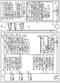
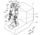
 実施の形態2は、ロボットが測距ライダを備え、測距ライダが計測する点群データから周囲環境の3次元モデルを生成する機能を遠隔制御マニピュレータシステムに持たせた場合である。図11から図13を参照して、実施の形態2に係る遠隔制御マニピュレータシステムの構成を説明する。図11は、実施の形態2に係る遠隔制御マニピュレータシステムで使用されるロボットのヒューマノイド部の正面図である。図12は、実施の形態2に係る遠隔制御マニピュレータシステムで使用されるロボットのヒューマノイド部の左側面図である。図13は、実施の形態2に係る遠隔制御マニピュレータシステムの機能構成を示すブロック図である。
Embodiment 2.
The second embodiment is a case where the robot is provided with a distance measuring lidar, and the remote control manipulator system is provided with a function of generating a three-dimensional model of the surrounding environment from the point cloud data measured by the distance measuring lidar. The configuration of the remote control manipulator system according to the second embodiment will be described with reference to FIGS. 11 to 13. FIG. 11 is a front view of the humanoid portion of the robot used in the remote control manipulator system according to the second embodiment. FIG. 12 is a left side view of the humanoid portion of the robot used in the remote control manipulator system according to the second embodiment. FIG. 13 is a block diagram showing a functional configuration of the remote control manipulator system according to the second embodiment.
 図11および図12を参照して、ロボット1Aが図4および図5に示すロボット1とは異なる点を説明する。ロボット1Aが有するヒューマノイド部1HAは、右の前腕部11Dに測距ライダ16Rを有し、左の前腕部11Dに測距ライダ16Lを有し、胴体部11Aの前面に測距ライダ16Bを有する。測距ライダ16Rは、右の前腕部11Dの手首関節部12Cに近い正面側の部分に設ける。前腕部11Dの正面側とは、腕部11Jを下に垂らす基準状態においてヒューマノイド部1HAの正面に向く側である。測距ライダ16Lは、左の前腕部11Dの手首関節部12Cに近い正面側の部分に設ける。測距ライダ16R、16Lは、前腕部11Dの内側にレーザ光を放射するように前腕部11Dに搭載される。前腕部11Dの内側は、基準状態での前腕部11Dがロボット1Aの中心線に向う側である。ロボット1Aの中心線は、基準状態でのロボット1Aを正面から見る際に高さ方向に延在する。測距ライダ16Bは、胴体部11Aの正面の側に放射するように設けられる。なお、例えば測距ライダ16Rの1個だけをヒューマノイド部が有するようにしてもよい。 The difference between the robot 1A and the robot 1 shown in FIGS. 4 and 5 will be described with reference to FIGS. 11 and 12. The humanoid portion 1HA included in the robot 1A has a ranging rider 16R on the right forearm portion 11D, a ranging rider 16L on the left forearm portion 11D, and a ranging rider 16B on the front surface of the body portion 11A. The ranging rider 16R is provided on the front side portion of the right forearm portion 11D near the wrist joint portion 12C. The front side of the forearm portion 11D is the side facing the front of the humanoid portion 1HA in the reference state in which the arm portion 11J is hung down. The ranging rider 16L is provided on the front side portion of the left forearm portion 11D near the wrist joint portion 12C. The ranging lidars 16R and 16L are mounted on the forearm portion 11D so as to radiate a laser beam inside the forearm portion 11D. The inside of the forearm portion 11D is the side where the forearm portion 11D in the reference state faces the center line of the robot 1A. The center line of the robot 1A extends in the height direction when the robot 1A in the reference state is viewed from the front. The ranging rider 16B is provided so as to radiate to the front side of the body portion 11A. In addition, for example, the humanoid unit may have only one of the distance measuring lidar 16R.
 測距ライダ16R、16L、16Bは、スキャン(走査)しながらレーザ光を放射し、レーザ光を放射してから物体に反射されてきた反射レーザ光が受信されるまでの時間に基づき、レーザ光を放射した方向に存在する事物までの距離を計測する。測距ライダ16R、16L、16Bは、それぞれライダ点群生データ72を生成する。測距ライダがレーザ光をスキャンする範囲の中心になる方向を、測距ライダの放射方向と呼ぶ。測距ライダの放射方向を測距方向とも呼ぶ。ライダ点群生データ72は、測距ライダ16R、16L、16Bごとに決まる放射方向に対する角度ごとに、その角度に存在する事物までの距離を表現するデータの集合である。 The ranging lidars 16R, 16L, 16B emit laser light while scanning, and the laser light is based on the time from the emission of the laser light to the reception of the reflected laser light reflected by the object. Measure the distance to an object that exists in the direction of radiation. The ranging lidars 16R, 16L, and 16B generate lidar point cluster data 72, respectively. The direction centered on the range in which the ranging rider scans the laser beam is called the radiation direction of the ranging rider. The radiation direction of the distance measuring lidar is also called the distance measuring direction. The rider point group data 72 is a set of data representing the distance to an object existing at each angle with respect to the radiation direction determined for each of the distance measuring riders 16R, 16L, and 16B.
 ロボット1Aが有する制御部7Aは、測距ライダ16R、16L、16Bを動作させるかどうかも制御する。制御部7Aが有する記憶部15Aは、測距ライダ16R、16L、16Bが計測するライダ点群生データ72も記憶する。制御部7を変更しないで、測距ライダ16R、16L、16Bを動作させるかどうかを制御装置3Aが制御部7を介さないで制御し、ライダ点群生データ72が制御部7を介さないで制御装置3Aに送信されてもよい。 The control unit 7A possessed by the robot 1A also controls whether or not the distance measuring lidars 16R, 16L, and 16B are operated. The storage unit 15A included in the control unit 7A also stores the lidar point cluster data 72 measured by the distance measuring lidars 16R, 16L, and 16B. The control device 3A controls whether or not the distance measuring lidars 16R, 16L, and 16B are operated without changing the control unit 7, and the rider point cluster data 72 is controlled without the control unit 7. It may be transmitted to the device 3A.
 遠隔制御マニピュレータシステム100Aの機能構成を示す図13について、実施の形態1の場合の図2とは異なる点を説明する。制御装置3Aは、構造データ記憶部32A、状態データ記憶部33A、ロボットモデル生成部34Aおよび環境モデル生成部35Aを変更している。構造データ記憶部32Aは、ライダ構造データ84も記憶する。ライダ構造データ84は、測距ライダ16R、16L、16Bのそれぞれの放射方向、スキャン角度範囲を記憶する。放射方向は、右または左の前腕部11Dあるいは胴体部11Aに対する角度を定義するデータである。スキャン角度範囲は、レーザ光をスキャンする角度の範囲を規定するデータである。スキャン角度範囲は、例えば水平方向に240度、上下方向に90度などのスキャンする角度の範囲である。ライダ構造データ84は、測距センサである測距ライダ16R、16L、16Bの構造を表す測距センサ構造データである。 FIG. 13 showing the functional configuration of the remote control manipulator system 100A will be described as different from FIG. 2 in the case of the first embodiment. The control device 3A modifies the structural data storage unit 32A, the state data storage unit 33A, the robot model generation unit 34A, and the environment model generation unit 35A. The structural data storage unit 32A also stores the rider structure data 84. The rider structure data 84 stores the radial directions and scan angle ranges of the ranging riders 16R, 16L, and 16B, respectively. The radial direction is data that defines the angle with respect to the right or left forearm portion 11D or the body portion 11A. The scan angle range is data that defines a range of angles for scanning the laser beam. The scan angle range is a range of scan angles such as 240 degrees in the horizontal direction and 90 degrees in the vertical direction. The rider structure data 84 is distance measuring sensor structure data representing the structure of the distance measuring riders 16R, 16L, 16B which are distance measuring sensors.
 状態データ記憶部33Aは、ロボット3次元モデル64Aを変更し、カメラ周囲点群データ71、ライダ点群生データ72、ライダ点群データ74およびライダ周囲点群データ75を追加している。ロボット3次元モデル64Aは、ライダ姿勢73も有する。ライダ姿勢73は、測距ライダ16R、16L、16Bの現場座標系における位置と放射方向を表すデータである。ライダ姿勢73は、測距ライダ16R、16L、16Bの3次元モデルである。 The state data storage unit 33A modifies the robot 3D model 64A and adds camera peripheral point cloud data 71, rider point cloud data 72, rider point cloud data 74, and rider peripheral point cloud data 75. The robot 3D model 64A also has a rider posture 73. The rider posture 73 is data representing the position and the radial direction of the distance measuring riders 16R, 16L, and 16B in the field coordinate system. The rider posture 73 is a three-dimensional model of the ranging riders 16R, 16L, and 16B.
 ライダ点群生データ72は、測距ライダ16R、16L、16Bが計測した点群のデータである。ライダ点群生データ72は、測距ライダ16R、16L、16Bの放射方向を基準とするデータである。ライダ点群生データ72において、スキャンする範囲内において隣接する方向との間で計測した距離が大きく変化する方向を不連続点として認識する。ライダ点群データ74は、ライダ点群生データ72を現場座標系における値に変換したデータである。ライダ点群データ74においても、不連続点を認識しておく。 The rider point cloud data 72 is the data of the point cloud measured by the ranging riders 16R, 16L, 16B. The rider point cluster data 72 is data based on the radiation direction of the ranging riders 16R, 16L, 16B. In the rider point cluster data 72, the direction in which the measured distance greatly changes from the adjacent direction within the scanning range is recognized as a discontinuous point. The rider point cloud data 74 is data obtained by converting the rider point cloud data 72 into values in the field coordinate system. The discontinuity point is also recognized in the rider point cloud data 74.
 ロボットモデル生成部34Aは、ライダ構造データ84も参照して、カメラ姿勢65およびライダ姿勢73を含むロボット3次元モデル64Aを生成する。 The robot model generation unit 34A also refers to the rider structure data 84 to generate a robot three-dimensional model 64A including the camera posture 65 and the rider posture 73.
 環境モデル生成部35Aは、不連続点抽出部47、ライダ座標変換部48、ライダ点群整合部49および点群選択生成部50を追加し、カメラ点群整合部46Aを変更している。カメラ点群整合部46Aは、周囲点群データ68ではなくカメラ周囲点群データ71を生成する。カメラ点群整合部46Aは、カメラ点群整合部46と同様にカメラ点群データ67を処理する。カメラ周囲点群データ71は、カメラ周囲環境モデルである。カメラ周囲環境モデルは、右カメラ2Rおよび左カメラ2Lが撮影した画像から生成される周囲環境モデルである。環境モデル生成部35Aは、カメラ周囲環境モデルを生成する画像処理モデル生成部である。 The environment model generation unit 35A adds a discontinuity point extraction unit 47, a rider coordinate conversion unit 48, a rider point cloud matching unit 49, and a point cloud selection generation unit 50, and changes the camera point cloud matching unit 46A. The camera point cloud matching unit 46A generates the camera peripheral point cloud data 71 instead of the peripheral point cloud data 68. The camera point cloud matching unit 46A processes the camera point cloud data 67 in the same manner as the camera point cloud matching unit 46. The camera peripheral point cloud data 71 is a camera peripheral environment model. The camera ambient environment model is an ambient environment model generated from images taken by the right camera 2R and the left camera 2L. The environment model generation unit 35A is an image processing model generation unit that generates an environment model around the camera.
 不連続点抽出部47は、ライダ点群生データ72を取り込み、ライダ点群生データ72を処理して不連続点を抽出する。ライダ座標変換部48は、ライダ姿勢73を参照してライダ点群生データ72を現場座標系での位置データであるライダ点群データ74に変換する。ライダ点群整合部49は、ライダ周囲点群データ75を生成する。ライダ周囲点群データ75は、周囲環境として存在する各事物への方向と距離を表現するデータである。ライダ点群整合部49は、異なるライダ姿勢73でのライダ点群データ74を不連続点の位置が一致または位置の差が小さくなるようにつなげてライダ周囲点群データ75を生成する。異なるライダ姿勢73とは、少なくとも1個の測距ライダ16の位置および姿勢の少なくとも一方が異なることである。同じライダ姿勢73でのライダ点群データ74の平均をとってライダ点群データ74とし、あるライダ姿勢73でのライダ点群データ74を、別のライダ姿勢73でのライダ点群データ74と連結して、ライダ周囲点群データ75を生成してもよい。ライダ周囲点群データ75は、周囲環境までの距離と方向を含む測距データである。測距ライダ16R、16L、16Bは、測距データを計測する測距センサである。ライダ周囲点群データ75は、センサ周囲環境モデルである。センサ周囲環境モデルは、測距データから生成された周囲環境モデルである。環境モデル生成部35Aは、測距センサの位置と測距方向に基づき測距データを処理して、センサ周囲環境モデルを生成する測距データ処理モデル生成部である。 The discontinuity extraction unit 47 takes in the rider point cluster data 72, processes the rider point cluster data 72, and extracts the discontinuity. The rider coordinate conversion unit 48 converts the rider point cloud data 72 into the rider point cloud data 74, which is the position data in the field coordinate system, with reference to the rider posture 73. The rider point cloud matching unit 49 generates the rider peripheral point cloud data 75. The rider peripheral point cloud data 75 is data expressing the direction and distance to each object existing as the surrounding environment. The rider point cloud matching unit 49 generates the rider peripheral point cloud data 75 by connecting the rider point cloud data 74 in different rider postures 73 so that the positions of the discontinuous points match or the difference in position becomes small. The different rider posture 73 means that at least one of the positions and postures of at least one ranging rider 16 is different. The average of the rider point cloud data 74 in the same rider posture 73 is taken as the rider point cloud data 74, and the rider point cloud data 74 in one rider posture 73 is connected to the rider point cloud data 74 in another rider posture 73. Then, the lidar peripheral point cloud data 75 may be generated. The rider peripheral point cloud data 75 is distance measurement data including the distance and direction to the surrounding environment. The distance measuring lidars 16R, 16L, and 16B are distance measuring sensors that measure distance measuring data. The rider peripheral point cloud data 75 is a sensor ambient environment model. The sensor ambient environment model is an ambient environment model generated from ranging data. The environment model generation unit 35A is a distance measurement data processing model generation unit that processes distance measurement data based on the position and distance measurement direction of the distance measurement sensor to generate a sensor surrounding environment model.
 ライダ周囲点群データ75を生成した後に新たなライダ点群データ74が生成される場合は、ライダ点群整合部49は、ライダ点群データ74によりライダ周囲点群データ75を修正する。新たなライダ点群データ74で事物の位置が変化している場合は、その事物に関するライダ周囲点群データ75での点群データは、新たな位置に移動させる。 When a new rider point cloud data 74 is generated after the rider point cloud data 75 is generated, the rider point cloud matching unit 49 modifies the rider point cloud data 75 with the rider point cloud data 74. When the position of the object is changed in the new lidar point cloud data 74, the point cloud data in the lidar peripheral point cloud data 75 regarding the object is moved to the new position.
 制御装置3Aにおける周囲点群データ68は、カメラ周囲点群データ71またはライダ周囲点群データ75の何れか一方を選択した点群データである。点群選択生成部50は、カメラ周囲点群データ71またはライダ周囲点群データ75の何れか一方を選択して、周囲点群データ68とする。カメラ周囲点群データ71が生成できる場合は、点群選択生成部50はカメラ周囲点群データ71を周囲点群データ68とする。 The peripheral point cloud data 68 in the control device 3A is point cloud data in which either the camera peripheral point cloud data 71 or the rider peripheral point cloud data 75 is selected. The point cloud selection generation unit 50 selects either the camera peripheral point cloud data 71 or the rider peripheral point cloud data 75 to obtain the peripheral point cloud data 68. When the camera peripheral point cloud data 71 can be generated, the point cloud selection generation unit 50 sets the camera peripheral point cloud data 71 as the peripheral point cloud data 68.
 図14を参照して、動作を説明する。図14は、実施の形態2に係る遠隔制御マニピュレータシステムでロボットを遠隔制御する手順を説明するフローチャートである。図14について、実施の形態1の場合の図8とは異なる点を説明する。 The operation will be described with reference to FIG. FIG. 14 is a flowchart illustrating a procedure for remotely controlling a robot with the remote control manipulator system according to the second embodiment. FIG. 14 will be described which is different from FIG. 8 in the case of the first embodiment.
 ステップS01Aで、ライダ構造データ84も構造データ記憶部32Aに記憶させる。 In step S01A, the rider structure data 84 is also stored in the structure data storage unit 32A.
 ステップS03Aで、測距ライダ16R、16L、16Bに対しても補正パラメータを求める。ロボット1Aに校正用の姿勢をとらせて、ロボット1Aに対して決められた位置に定規物体を配置する。右カメラ2Rおよび左カメラ2Lは、定規物体を撮影する。撮影した画像から定規物体までの距離と定規物体の長さを計測する。測距ライダ16R、16L、16Bは、定規物体が含まれる空間をレーザ光でスキャンして、定規物体の方向と距離を計測する。何点かの距離で、右カメラ2Rおよび左カメラ2Lは定規物体を撮影して計測し、測距ライダ16R、16L、16Bは、定規物体が含まれる空間をレーザ光でスキャンして、定規物体の方向と距離を計測する。計測した距離および長さが実際の距離および長さと一致するように、右カメラ2Rおよび左カメラ2Lの換算係数とオフセット値を求め、測距ライダ16R、16L、16Bの換算係数とオフセット値を求める。 In step S03A, the correction parameters are also obtained for the distance measuring lidars 16R, 16L, and 16B. The robot 1A is made to take a posture for calibration, and the ruler object is placed at a position determined with respect to the robot 1A. The right camera 2R and the left camera 2L photograph a ruler object. Measure the distance from the captured image to the ruler object and the length of the ruler object. The ranging lidars 16R, 16L, 16B scan the space including the ruler object with a laser beam to measure the direction and distance of the ruler object. At some distance, the right camera 2R and the left camera 2L photograph and measure the ruler object, and the distance measuring riders 16R, 16L, 16B scan the space containing the ruler object with laser light, and the ruler object. Measure the direction and distance of. Obtain the conversion coefficient and offset value of the right camera 2R and the left camera 2L, and obtain the conversion coefficient and offset value of the distance measuring lidar 16R, 16L, 16B so that the measured distance and length match the actual distance and length. ..
 ステップS04Aで、物体20とその周囲環境の3次元モデルであるカメラ周囲点群データ71およびライダ周囲点群データ75を初期生成する。S04Aでの動作は、図15に示すフローチャートで説明する。 In step S04A, the camera peripheral point cloud data 71 and the rider peripheral point cloud data 75, which are three-dimensional models of the object 20 and its surrounding environment, are initially generated. The operation in S04A will be described with reference to the flowchart shown in FIG.
 ステップS06Aで、右カメラ2Rおよび左カメラ2Lが物体20とその周囲を撮影し、測距ライダ16R、16L、16Bがレーザ光をスキャンし、測距しながらヒューマノイド部1HAを動かして物体20を片方のハンド部11Eで把持させる。S06Aでの動作は、図16と図17に示すフローチャートで説明する。図16と図17は、実施の形態2に係る遠隔制御マニピュレータシステムでロボットが物体を把持する際に遠隔制御する手順を説明するフローチャートである。図16がフローチャートの前半部で、図17が後半部である。図16は、最初にモデル画像53を表示するまでの手順を示す。図17は、3D画像52およびモデル画像53を見ながらオペレータ30が腕部11Jを操作して物体20を把持するまでの手順を示す。 In step S06A, the right camera 2R and the left camera 2L photograph the object 20 and its surroundings, the distance measuring lidars 16R, 16L, and 16B scan the laser beam, and the humanoid unit 1HA is moved while measuring the distance to move the object 20 to one side. It is gripped by the hand portion 11E of. The operation in S06A will be described with reference to the flowcharts shown in FIGS. 16 and 17. 16 and 17 are flowcharts illustrating a procedure for remote control when a robot grips an object in the remote control manipulator system according to the second embodiment. FIG. 16 is the first half of the flowchart, and FIG. 17 is the second half. FIG. 16 shows a procedure until the model image 53 is first displayed. FIG. 17 shows a procedure until the operator 30 operates the arm portion 11J to grip the object 20 while looking at the 3D image 52 and the model image 53.
 図15は、実施の形態2に係る遠隔制御マニピュレータシステムで周囲点群データを初期生成する手順を説明するフローチャートである。図15について、実施の形態1の場合の図9とは異なる点を説明する。ステップS13Aで、姿勢センサ92が姿勢データ57を計測し、ライダ姿勢73およびカメラ姿勢65を含むロボット3次元モデル64Aを生成する。 FIG. 15 is a flowchart illustrating a procedure for initially generating peripheral point cloud data in the remote control manipulator system according to the second embodiment. FIG. 15 will be described which is different from FIG. 9 in the case of the first embodiment. In step S13A, the posture sensor 92 measures the posture data 57 and generates a robot 3D model 64A including the rider posture 73 and the camera posture 65.
 ステップS14Aで、右カメラ2Rおよび左カメラ2Lが物体20を含む画像を撮影し、撮影した画像からカメラ周囲点群データ71を生成または修正する。S15Aで、必要十分な範囲および精度でカメラ周囲点群データ71が生成できたかチェックする。周囲点群データ68ではなくカメラ周囲点群データ71を処理対象とする点で、S14AおよびS15AはS14およびS15とは異なる。 In step S14A, the right camera 2R and the left camera 2L take an image including the object 20, and the camera peripheral point cloud data 71 is generated or modified from the taken image. In S15A, it is checked whether the camera peripheral point cloud data 71 can be generated with a necessary and sufficient range and accuracy. S14A and S15A are different from S14 and S15 in that the camera peripheral point cloud data 71 is processed instead of the peripheral point cloud data 68.
 必要十分な範囲および精度でカメラ周囲点群データ71が生成できている(S15AでYES)場合は、ステップS19~S25でライダ周囲点群データ75を生成する。S19で、測距ライダ16R、16L、16Bがレーダ光をスキャンしながら放射し、ライダ点群データ74を生成し、ライダ周囲点群データ75を生成または修正する。 If the camera peripheral point cloud data 71 can be generated with a necessary and sufficient range and accuracy (YES in S15A), the rider peripheral point cloud data 75 is generated in steps S19 to S25. In S19, the ranging riders 16R, 16L, 16B radiate while scanning the radar light, generate the rider point cloud data 74, and generate or modify the rider peripheral point cloud data 75.
 ステップS20で、必要十分な範囲および精度でライダ周囲点群データ75が生成できたかチェックする。必要十分な範囲および精度でライダ周囲点群データ75が生成できている(S20でYES)場合は、処理を終了する。 In step S20, it is checked whether the lidar peripheral point cloud data 75 can be generated with a necessary and sufficient range and accuracy. If the lidar peripheral point cloud data 75 can be generated with a necessary and sufficient range and accuracy (YES in S20), the process ends.
 必要十分な範囲および精度でライダ周囲点群データ75が生成できていない(S20でNO)場合は、ステップS21で別の姿勢をとるかチェックする。別の姿勢をとる(S21でYES)場合は、ステップS22でヒューマノイド部1HAに別の姿勢をとらせる。 If the lidar peripheral point cloud data 75 could not be generated with the necessary and sufficient range and accuracy (NO in S20), check whether to take a different posture in step S21. When taking a different posture (YES in S21), the humanoid portion 1HA is made to take a different posture in step S22.
 別の姿勢をとらない(S21でNO)場合は、ステップS23でロボット1を別の位置に移動させる。ステップS24で、位置センサ91が車両姿勢56を計測する。S24またはS22の実行後に、ステップS25で、姿勢センサ92が姿勢データ57を計測し、ライダ姿勢73およびカメラ姿勢65を含むロボット3次元モデル64Aを生成する。そして、S19へ戻る。 If the robot 1 does not take a different posture (NO in S21), the robot 1 is moved to another position in step S23. In step S24, the position sensor 91 measures the vehicle posture 56. After the execution of S24 or S22, in step S25, the posture sensor 92 measures the posture data 57 and generates a robot three-dimensional model 64A including the rider posture 73 and the camera posture 65. Then, it returns to S19.
 図16と図17について、実施の形態1の場合の図10とは異なる点を説明する。図16と図17に示すフローチャートは、カメラ周囲点群データ71またはライダ周囲点群データ75の何れか一方を周囲点群データ68とする場合である。図16と図17に示すフローチャートでは、カメラ周囲点群データ71を優先して使用する。また、カメラ点群データ67を作成できない場合は、ライダ点群データ74だけから周囲点群データ68を生成する。ライダ点群データ74だけから周囲点群データ68を生成する状態で、カメラ点群データ67を作成できるかチェックしてもよい。カメラ点群データ67を作成できる場合は、カメラ点群データ67およびカメラ周囲点群データ71を生成して、カメラ周囲点群データ71を優先して使用して周囲点群データ68を生成してもよい。 16 and 17 will be described as different from FIG. 10 in the case of the first embodiment. The flowcharts shown in FIGS. 16 and 17 are cases where either the camera peripheral point cloud data 71 or the rider peripheral point cloud data 75 is used as the peripheral point cloud data 68. In the flowcharts shown in FIGS. 16 and 17, the camera peripheral point cloud data 71 is preferentially used. If the camera point cloud data 67 cannot be created, the peripheral point cloud data 68 is generated only from the rider point cloud data 74. It may be checked whether the camera point cloud data 67 can be created in a state where the peripheral point cloud data 68 is generated only from the rider point cloud data 74. When the camera point cloud data 67 can be created, the camera point cloud data 67 and the camera peripheral point cloud data 71 are generated, and the camera peripheral point cloud data 71 is preferentially used to generate the peripheral point cloud data 68. May be good.
 ステップS32Aで、ライダ姿勢73およびカメラ姿勢65を含むロボット3次元モデル64Aを生成する。 In step S32A, a robot 3D model 64A including a rider posture 73 and a camera posture 65 is generated.
 ステップS38Aで、カメラ点群データ67によりカメラ周囲点群データ71を修正する。そして、ステップS46で、表示状態をカメラ利用可と設定し、点群選択生成部50がカメラ周囲点群データ71を選択して周囲点群データ68とする。ここで、表示状態は、点群選択生成部50がカメラ周囲点群データ71を選択できるかどうかを制御するフラグである。そして、S39で、モデル統合部36が周囲点群データ68とロボット3次元モデル64Aを統合して統合3次元モデル69Aを生成する。 In step S38A, the camera peripheral point cloud data 71 is corrected by the camera point cloud data 67. Then, in step S46, the display state is set to be camera usable, and the point cloud selection generation unit 50 selects the camera peripheral point cloud data 71 and sets it as the peripheral point cloud data 68. Here, the display state is a flag that controls whether or not the point cloud selection generation unit 50 can select the camera peripheral point cloud data 71. Then, in S39, the model integration unit 36 integrates the peripheral point cloud data 68 and the robot three-dimensional model 64A to generate the integrated three-dimensional model 69A.
 右カメラ2Rおよび左カメラ2Lの両方の視野内に物体20が存在しない(S35でNO)場合、あるいはカメラ点群データ67を生成できていない(S37でNO)場合は、ステップS47~S54でライダ周囲点群データ75を生成する。S47で、測距ライダ16R、16L、16Bがスキャンしながらレーザ光を放射して周囲の事物との距離を計測し、ライダ点群データ74を生成する。なお、不連続点抽出部47が不連続点を抽出できない場合は、ライダ点群データ74を生成できていないとする。ステップS48で、ライダ点群データ74が生成できているかチェックする。ライダ点群データ74が生成できている(S48でYES)場合は、ステップS49で、ライダ点群データ74によりライダ周囲点群データ75を修正する。ステップS50で、表示状態をカメラ利用不可と設定し、ライダ周囲点群データ75を選択して周囲点群データ68とする。そして、S39へ進む。 If the object 20 does not exist in the fields of view of both the right camera 2R and the left camera 2L (NO in S35), or if the camera point cloud data 67 cannot be generated (NO in S37), the rider in steps S47 to S54. Peripheral point cloud data 75 is generated. In S47, the distance measuring lidars 16R, 16L, and 16B emit laser light while scanning, measure the distance to surrounding objects, and generate the lidar point cloud data 74. If the discontinuity extraction unit 47 cannot extract the discontinuity, it is assumed that the rider point cloud data 74 cannot be generated. In step S48, it is checked whether the rider point cloud data 74 can be generated. If the rider point cloud data 74 has been generated (YES in S48), the rider point cloud data 74 modifies the rider peripheral point cloud data 75 in step S49. In step S50, the display state is set to be unusable for the camera, and the lidar peripheral point cloud data 75 is selected as the peripheral point cloud data 68. Then, proceed to S39.
 ライダ点群データ74が生成できていない(S48でNO)場合は、周囲環境に存在する障害物などが原因でライダでの測距ができない場合に対応する。ライダ点群データ74が生成できていない(S48でNO)場合は、ステップS51で、測距ライダ16R、16Lの少なくとも一方が不連続点を有するライダ点群データ74が生成できるように、物体20を別視点から見る位置に右および左の腕部11Jの少なくとも一方を移動させる。 If the rider point cloud data 74 could not be generated (NO in S48), it corresponds to the case where the distance measurement with the rider is not possible due to obstacles existing in the surrounding environment. If the rider point cloud data 74 has not been generated (NO in S48), the object 20 can generate the rider point cloud data 74 in which at least one of the distance measuring riders 16R and 16L has a discontinuity in step S51. Move at least one of the right and left arm portions 11J to a position viewed from another viewpoint.
 ステップS52で、制御周期Tcが経過したかチェックする。Tcが経過している(S52でYES)場合は、ステップS53で、姿勢センサ92が姿勢データ57を計測する。ステップS54で、車両姿勢56および姿勢データ57からカメラ姿勢65およびライダ姿勢73を含むロボット3次元モデル64Aを生成する。S54の実行後またはTcが経過していない(S52でNO)場合は、S47へ戻る。 In step S52, it is checked whether the control cycle Tc has elapsed. If Tc has elapsed (YES in S52), the attitude sensor 92 measures the attitude data 57 in step S53. In step S54, the robot three-dimensional model 64A including the camera posture 65 and the rider posture 73 is generated from the vehicle posture 56 and the posture data 57. After the execution of S54 or when Tc has not elapsed (NO in S52), the process returns to S47.
 オペレータ30がヒューマノイド部1HAを操作中の処理を示す図17について説明する。S43からS45は、図10と同様である。S43で、オペレータ30がヒューマノイド部1HAを動かす。S44で、ハンド部11Eの感圧センサ95の出力(触覚データ60)が接触ありかチェックする。感圧センサ95の出力が接触ありであることは、ハンド部11Eが物体に接触していることを意味する。感圧センサ95の出力が接触ありである(S44でYES)場合は、処理を終了する。感圧センサ95の出力が接触ありではない(S44でNO)場合は、S45で、決められた制御周期Tcが経過したかチェックする。 FIG. 17 showing a process in which the operator 30 is operating the humanoid unit 1HA will be described. S43 to S45 are the same as in FIG. In S43, the operator 30 moves the humanoid unit 1HA. In S44, it is checked whether the output (tactile data 60) of the pressure sensor 95 of the hand portion 11E is in contact. The fact that the output of the pressure sensor 95 is in contact means that the hand portion 11E is in contact with the object. If the output of the pressure sensor 95 is in contact (YES in S44), the process ends. If the output of the pressure sensor 95 is not in contact (NO in S44), it is checked in S45 whether the determined control cycle Tc has elapsed.
 Tcが経過している(S45でYES)場合は、ステップS55で、姿勢センサ92が姿勢データ57を計測する。ステップS56で、車両姿勢56および姿勢データ57からカメラ姿勢65およびライダ姿勢73を含むロボット3次元モデル64Aを生成する。S56の実行後またはTcが経過していない(S45でNO)場合は、ステップS57で、右カメラ2Rおよび左カメラ2Lが物体20の画像を撮影する。 If Tc has elapsed (YES in S45), the attitude sensor 92 measures the attitude data 57 in step S55. In step S56, the robot three-dimensional model 64A including the camera posture 65 and the rider posture 73 is generated from the vehicle posture 56 and the posture data 57. After the execution of S56 or when Tc has not elapsed (NO in S45), in step S57, the right camera 2R and the left camera 2L take an image of the object 20.
 ステップS58で、立体視表示装置4が3D画像52を立体視表示する。S58と並行してステップS59で、表示状態がカメラ利用可かチェックする。カメラ利用可である(S59でYES)場合は、ステップS60で右カメラ2Rおよび左カメラ2Lの両方の視野内に物体20が存在するかチェックする。右カメラ2Rおよび左カメラ2Lの両方の視野内に物体20が存在する(S60でYES)場合は、ステップS61で、撮影した画像からカメラ点群データ67を生成する。ステップS62で、カメラ点群データ67によりカメラ周囲点群データ71を修正する。ステップS63で、カメラ周囲点群データ71を選択して周囲点群データ68とする。ステップS64で、周囲点群データ68とロボット3次元モデル64Aを統合して統合3次元モデル69を生成する。ステップS65で、統合3次元モデル69からモデル画像53を生成する。ステップS66で、表示装置5がモデル画像53を表示する。ステップS67で、オペレータ30が立体視表示装置4に立体視表示される3D画像52または表示装置5に表示されたモデル画像53を見る。そして、S43へ戻る。 In step S58, the stereoscopic display device 4 displays the 3D image 52 in stereoscopic view. In parallel with S58, in step S59, it is checked whether the display state can be used by the camera. If the camera is available (YES in S59), it is checked in step S60 whether the object 20 exists in the fields of view of both the right camera 2R and the left camera 2L. When the object 20 is present in the fields of view of both the right camera 2R and the left camera 2L (YES in S60), the camera point cloud data 67 is generated from the captured image in step S61. In step S62, the camera peripheral point cloud data 71 is modified by the camera point cloud data 67. In step S63, the camera peripheral point cloud data 71 is selected and used as the peripheral point cloud data 68. In step S64, the peripheral point cloud data 68 and the robot 3D model 64A are integrated to generate an integrated 3D model 69. In step S65, the model image 53 is generated from the integrated three-dimensional model 69. In step S66, the display device 5 displays the model image 53. In step S67, the operator 30 sees the 3D image 52 stereoscopically displayed on the stereoscopic display device 4 or the model image 53 displayed on the display device 5. Then, it returns to S43.
 表示状態がカメラ利用可ではない(S59でNO)場合、あるいは右カメラ2Rおよび左カメラ2Lの何れか少なくとも一方の視野内に物体20が存在しない(S60でNO)場合は、ステップS68で、測距ライダ16R、16L、16Bは、スキャンしながらレーザ光を放射して測距し、ライダ点群データ74を生成する。ステップS69で、ライダ点群データ74によりライダ周囲点群データ75を修正する。ステップS70で、表示状態をカメラ利用不可とし、点群選択生成部50がライダ周囲点群データ75を選択して周囲点群データ68とする。そして、S64へ進む。 If the display state is not available for the camera (NO in S59), or if the object 20 does not exist in the field of view of at least one of the right camera 2R and the left camera 2L (NO in S60), the measurement is performed in step S68. The distance riders 16R, 16L, and 16B radiate a laser beam to measure the distance while scanning, and generate lidar point group data 74. In step S69, the rider peripheral point cloud data 75 is modified by the rider point cloud data 74. In step S70, the display state is set so that the camera cannot be used, and the point cloud selection generation unit 50 selects the lidar peripheral point cloud data 75 and sets it as the peripheral point cloud data 68. Then, proceed to S64.
 遠隔制御マニピュレータシステム100Aでも、オペレータ30は、立体視表示された3D画像52およびモデル画像53を自由に切り替えて見ることができる。モデル画像53は、オペレータ30が指定した視点からロボット1および物体20を見る画像である。オペレータ30は、ロボット1Aを遠隔制御して、物体20を押す、引く、把持する等の作業を、従来よりも正確に、かつ容易に実施できる。その他の点でも、遠隔制御マニピュレータシステム100Aは、遠隔制御マニピュレータシステム100と同様に動作して、同様な効果が得られる。 Even in the remote control manipulator system 100A, the operator 30 can freely switch between the stereoscopically displayed 3D image 52 and the model image 53 for viewing. The model image 53 is an image of viewing the robot 1 and the object 20 from the viewpoint designated by the operator 30. The operator 30 can remotely control the robot 1A to perform operations such as pushing, pulling, and grasping the object 20 more accurately and easily than before. In other respects, the remote control manipulator system 100A operates in the same manner as the remote control manipulator system 100, and the same effect can be obtained.
 ロボット1Aが測距ライダ16を備えるので、物体20およびその周囲環境の3次元モデルである周囲環境モデルを、遠隔制御マニピュレータシステム100Aは、遠隔制御マニピュレータシステム100よりも容易にかつ正確に生成できる。 Since the robot 1A includes the distance measuring lidar 16, the remote control manipulator system 100A can easily and accurately generate an ambient environment model, which is a three-dimensional model of the object 20 and its surrounding environment, as compared with the remote control manipulator system 100.
 周囲点群データは、ライダ周囲点群データ75を優先して使用してもよい。周囲点群データは、カメラ周囲点群データ71またはライダ周囲点群データ75の両方から生成した点群データでもよい。点群選択生成部50は、カメラ周囲点群データ71またはライダ周囲点群データ75の何れか一方を選択して、周囲点群データ68とする。あるいは、点群選択生成部50は、カメラ周囲点群データ71またはライダ周囲点群データ75の両方から周囲点群データ68を生成する。点群選択生成部50は、カメラ周囲点群データ71およびライダ周囲点群データ75の少なくとも一方を選択して周囲点群データ68を生成する。 As the peripheral point cloud data, the rider peripheral point cloud data 75 may be used with priority. The peripheral point cloud data may be point cloud data generated from both the camera peripheral point cloud data 71 and the rider peripheral point cloud data 75. The point cloud selection generation unit 50 selects either the camera peripheral point cloud data 71 or the rider peripheral point cloud data 75 to obtain the peripheral point cloud data 68. Alternatively, the point cloud selection generation unit 50 generates the peripheral point cloud data 68 from both the camera peripheral point cloud data 71 and the rider peripheral point cloud data 75. The point cloud selection generation unit 50 selects at least one of the camera peripheral point cloud data 71 and the rider peripheral point cloud data 75 to generate the peripheral point cloud data 68.
 点群選択生成部は、カメラ周囲点群データ71およびライダ周囲点群データ75の平均をとるなどして周囲点群データ68としてもよい。あるいは、点群選択生成部は、周囲点群データ68の一部はカメラ周囲点群データ71を選択し、別の一部はライダ周囲点群データ75を選択してもよい。点群選択生成部にカメラ周囲点群データ71およびライダ周囲点群データ75の両方が入力される場合に、点群選択生成部が生成する周囲点群データ68をカメラ周囲点群データ71およびライダ周囲点群データ75を融合した融合周囲環境モデルと呼ぶ。その場合の点群選択生成部は、融合周囲環境モデルである周囲点群データ68を生成する周囲環境モデル融合部である。点群選択生成部は、カメラ周囲点群データ71またはライダ周囲点群データ75の両方から生成する部分を有しない周囲点群データ68を生成してもよい。周囲点群データ68は、カメラ周囲点群データ71である部分を有しないものでもよい。周囲点群データ68は、ライダ周囲点群データ75である部分を有しないものでもよい。 The point cloud selection generation unit may use the peripheral point cloud data 68 by taking the average of the camera peripheral point cloud data 71 and the rider peripheral point cloud data 75. Alternatively, the point cloud selection generation unit may select the camera peripheral point cloud data 71 for a part of the peripheral point cloud data 68 and the lidar peripheral point cloud data 75 for another part. When both the camera peripheral point cloud data 71 and the rider peripheral point cloud data 75 are input to the point cloud selection generation unit, the peripheral point cloud data 68 generated by the point cloud selection generation unit is used as the camera peripheral point cloud data 71 and the rider. It is called a fusion ambient environment model in which the peripheral point cloud data 75 is fused. In that case, the point cloud selection generation unit is an ambient environment model fusion unit that generates ambient point cloud data 68, which is a fusion ambient environment model. The point cloud selection generation unit may generate the peripheral point cloud data 68 having no portion generated from both the camera peripheral point cloud data 71 and the rider peripheral point cloud data 75. The peripheral point cloud data 68 may not have a portion that is the camera peripheral point cloud data 71. The peripheral point cloud data 68 may not have a portion that is the lidar peripheral point cloud data 75.
 カメラ周囲点群データ71およびライダ周囲点群データ75の両方とも周囲点群データとして選択して、統合3次元モデルを生成してもよい。統合3次元モデルに基づき生成されるモデル画像には、カメラ周囲点群データ71およびライダ周囲点群データ75の両方が表示される。両方を表示する場合には、カメラ周囲点群データ71とライダ周囲点群データ75とで画像の表示色を変え、どちらの画像も透過する画像とする。透過する画像とすることで、カメラ周囲点群データ71のライダ周囲点群データ75の両方の画像を見ることができ、カメラ周囲点群データ71のライダ周囲点群データ75の背後のロボット1Aや周囲環境も見ることができる。 Both the camera peripheral point cloud data 71 and the rider peripheral point cloud data 75 may be selected as the peripheral point cloud data to generate an integrated 3D model. Both the camera peripheral point cloud data 71 and the rider peripheral point cloud data 75 are displayed in the model image generated based on the integrated 3D model. When both are displayed, the display color of the image is changed between the camera peripheral point cloud data 71 and the rider peripheral point cloud data 75, and both images are transparent. By making it a transparent image, both images of the lidar peripheral point cloud data 75 of the camera peripheral point cloud data 71 can be seen, and the robot 1A behind the lidar peripheral point cloud data 75 of the camera peripheral point cloud data 71 and the like. You can also see the surrounding environment.
 カメラ周囲点群データ71またはライダ周囲点群データ75のどちらを優先して表示するか、両方を表示するか、あるいはカメラ周囲点群データ71およびライダ周囲点群データ75を融合した融合周囲環境モデル表示するかを選択する指示を、オペレータ30が入力できるようにしてもよい。物体20を扱う処理を開始した後に、オペレータ30が表示方法を変更できるようにしてもよい。 Whether to display the camera peripheral point cloud data 71 or the rider peripheral point cloud data 75 with priority, or to display both, or a fused ambient environment model in which the camera peripheral point cloud data 71 and the rider peripheral point cloud data 75 are fused. The operator 30 may be able to input an instruction for selecting whether to display. The operator 30 may be able to change the display method after starting the process of handling the object 20.
 環境モデル生成部は、画像処理によりカメラ周囲点群データを生成せず、ライダ周囲点群データ75だけを生成するものでもよい。その場合の環境モデル生成部は、周囲環境モデルであるライダ周囲点群データ75とロボット3次元モデル64Aとを統合するモデル統合部を有する。 The environment model generation unit may generate only the lidar peripheral point cloud data 75 without generating the camera peripheral point cloud data by image processing. The environment model generation unit in that case has a model integration unit that integrates the lidar peripheral point cloud data 75, which is an ambient environment model, and the robot three-dimensional model 64A.
 測距ライダではなく、電波や超音波を放射することで周囲の物体までの距離を計測する測距センサを使用してもよい。必要十分なスキャン角度範囲および角度分解能で方向ごとの事物までの距離を計測できるものであれば、測距センサはどのようなものを使用してもよい。
 以上のことは、他の実施の形態にもあてはまる。
Instead of a distance measuring lidar, a distance measuring sensor that measures the distance to a surrounding object by radiating radio waves or ultrasonic waves may be used. Any range-finding sensor may be used as long as it can measure the distance to an object in each direction with a necessary and sufficient scan angle range and angle resolution.
The above also applies to other embodiments.
 実施の形態3.
 実施の形態3は、ロボットの3次元モデルを、目標姿勢に基づき生成するように実施の形態2を変更した場合である。目標姿勢は、オペレータ30が意図している制御後のロボット1Aの姿勢を表すデータである。図18を参照して、実施の形態3に係る遠隔制御マニピュレータシステムの構成を説明する。図18は、実施の形態3に係る遠隔制御マニピュレータシステムの機能構成を示すブロック図である。
Embodiment 3.
The third embodiment is a case where the second embodiment is modified so that the three-dimensional model of the robot is generated based on the target posture. The target posture is data representing the posture of the robot 1A after the control intended by the operator 30. The configuration of the remote control manipulator system according to the third embodiment will be described with reference to FIG. FIG. 18 is a block diagram showing a functional configuration of the remote control manipulator system according to the third embodiment.
 遠隔制御マニピュレータシステム100Bの機能構成を示す図18について、実施の形態2の場合の図13とは異なる点を説明する。遠隔制御マニピュレータシステム100Bを構成する制御装置3Bは、状態データ記憶部33B、ロボットモデル生成部34B、モデル統合部36Bおよびモデル画像生成部38Bを変更している。 FIG. 18 showing the functional configuration of the remote control manipulator system 100B will be described as different from FIG. 13 in the case of the second embodiment. The control device 3B constituting the remote control manipulator system 100B modifies the state data storage unit 33B, the robot model generation unit 34B, the model integration unit 36B, and the model image generation unit 38B.
 状態データ記憶部33Bは、2個のロボット3次元モデル64A、64Bを記憶する。状態データ記憶部33Bは、統合3次元モデル69Bとモデル画像53Bを記憶する。ロボット3次元モデル64Aは、現在のロボット1Aの姿勢を表す姿勢データ57に基づき生成されるロボット1Aの3次元モデルである。ロボット3次元モデル64Bは、目標姿勢54に基づき生成されるロボット1Aの3次元モデルである。目標姿勢54は、オペレータ30が入力する動作指示を実行後のロボット1Aの位置および姿勢を表すデータである。統合3次元モデル69Bおよびモデル画像53Bは、ロボット3次元モデル64Bに基づき生成される。説明を分かりやすくするために、ロボット3次元モデル64Aを現在3次元モデル64Aと呼び、ロボット3次元モデル64Bを目標3次元モデル64Bと呼ぶ。目標3次元モデル64Bは、オペレータ30が入力した目標姿勢54をロボット1Aがとる3次元モデルである。目標3次元モデル64Bは、ロボット1Aが動作指示に従う動作を実行後のマニピュレータモデルである目標マニピュレータモデルである。モデル画像53Bは、目標姿勢54をとるロボット1Aを指定された視点から見る画像である。 The state data storage unit 33B stores two robot three- dimensional models 64A and 64B. The state data storage unit 33B stores the integrated three-dimensional model 69B and the model image 53B. The robot 3D model 64A is a 3D model of the robot 1A generated based on the posture data 57 representing the current posture of the robot 1A. The robot three-dimensional model 64B is a three-dimensional model of the robot 1A generated based on the target posture 54. The target posture 54 is data representing the position and posture of the robot 1A after executing the operation instruction input by the operator 30. The integrated 3D model 69B and the model image 53B are generated based on the robot 3D model 64B. For the sake of clarity, the robot 3D model 64A is currently referred to as the 3D model 64A, and the robot 3D model 64B is referred to as the target 3D model 64B. The target three-dimensional model 64B is a three-dimensional model in which the robot 1A takes the target posture 54 input by the operator 30. The target three-dimensional model 64B is a target manipulator model that is a manipulator model after the robot 1A executes an operation according to an operation instruction. The model image 53B is an image of the robot 1A taking the target posture 54 viewed from a designated viewpoint.
 カメラ座標変換部45は、現在3次元モデル64Aに含まれるカメラ姿勢65に基づき、カメラ点群生データ66をカメラ点群データ67に変換する。ライダ座標変換部48は、現在3次元モデル64Aに含まれるライダ姿勢73に基づき、ライダ点群生データ72をライダ点群データ74に変換する。 The camera coordinate conversion unit 45 converts the camera point cloud data 66 into the camera point cloud data 67 based on the camera posture 65 currently included in the 3D model 64A. The rider coordinate conversion unit 48 converts the rider point cloud data 72 into the rider point cloud data 74 based on the rider posture 73 currently included in the three-dimensional model 64A.
 統合3次元モデル69Bは、目標3次元モデル64Bと現在の周囲環境を表す周囲点群データ68を統合した3次元モデルを表すデータである。状態データ記憶部33Bは、現在3次元モデル64Aと周囲点群データ68を統合した統合3次元モデルは記憶しない。モデル画像53Bは、統合3次元モデル69Bを視点データ70で指定される視点から見た画像である。モデル画像53Bは、表示装置5に表示される。 The integrated 3D model 69B is data representing a 3D model in which the target 3D model 64B and the surrounding point cloud data 68 representing the current surrounding environment are integrated. The state data storage unit 33B does not currently store the integrated 3D model that integrates the 3D model 64A and the peripheral point cloud data 68. The model image 53B is an image of the integrated three-dimensional model 69B viewed from the viewpoint specified by the viewpoint data 70. The model image 53B is displayed on the display device 5.
 ロボットモデル生成部34Bは、姿勢データ57を参照して現在3次元モデル64Aを生成し、目標姿勢54を参照して目標3次元モデル64Bを生成する。ロボットモデル生成部34Bは、目標マニピュレータモデルを生成する目標マニピュレータモデル生成部である。 The robot model generation unit 34B currently generates the 3D model 64A with reference to the posture data 57, and generates the target 3D model 64B with reference to the target posture 54. The robot model generation unit 34B is a target manipulator model generation unit that generates a target manipulator model.
 モデル統合部36Bは、目標3次元モデル64Bと周囲点群データ68とを統合して統合3次元モデル69Bを生成する。 The model integration unit 36B integrates the target 3D model 64B and the peripheral point cloud data 68 to generate an integrated 3D model 69B.
 モデル画像生成部38Bは、統合3次元モデル69Bを使用してモデル画像53Bを生成する。 The model image generation unit 38B generates the model image 53B using the integrated 3D model 69B.
 図19を参照して、動作を説明する。図19は、実施の形態に係る遠隔制御マニピュレータシステムでロボットを遠隔制御する手順を説明するフローチャートである。図19について、実施の形態2の場合の図14とは異なる点を説明する。 The operation will be described with reference to FIG. FIG. 19 is a flowchart illustrating a procedure for remotely controlling a robot with the remote control manipulator system according to the embodiment. FIG. 19 will be described which is different from FIG. 14 in the case of the second embodiment.
 周囲点群データ68を初期生成する際には、モデル画像53Bをオペレータ30に提示しないので、S04Aは変更していない。なお、周囲点群データ68を初期生成する際にモデル画像53Bを提示する場合には、S04Aを変更する。変更したS04Aを実行するフローチャートでは、図15に示す周囲点群データ68を初期生成する手順を説明するフローチャートを、以下のように修正する。S13A、S25で、ロボットモデル生成部34Bが、ライダ姿勢73とカメラ姿勢65を含む現在3次元モデル64Aと目標3次元モデル64Bを生成する。S13AまたはS25次の手順として、モデル画像53Bを表示装置5に表示する手順が追加される。 Since the model image 53B is not presented to the operator 30 when the peripheral point cloud data 68 is initially generated, S04A is not changed. When the model image 53B is presented when the peripheral point cloud data 68 is initially generated, S04A is changed. In the flowchart for executing the modified S04A, the flowchart for explaining the procedure for initially generating the peripheral point cloud data 68 shown in FIG. 15 is modified as follows. In S13A and S25, the robot model generation unit 34B generates the current 3D model 64A and the target 3D model 64B including the rider posture 73 and the camera posture 65. S13A or S25 As the next procedure, a procedure for displaying the model image 53B on the display device 5 is added.
 ステップS06Bは、目標姿勢54に基づくモデル画像53Bをオペレータ30に提示する点が、S06Aとは異なる。S06Bで、右カメラ2Rおよび左カメラ2Lが物体20とその周囲を撮影し、測距ライダ16R、16L、16Bがレーザ光をスキャンし測距しながら、ヒューマノイド部1HAを動かして物体20を片方のハンド部11Eで把持させる。S06Bでの動作は、図20と図21に示すフローチャートで説明する。図20と図21は、実施の形態2に係る遠隔制御マニピュレータシステムでロボットが物体を把持する際に遠隔制御する手順を説明するフローチャートである。 Step S06B is different from S06A in that the model image 53B based on the target posture 54 is presented to the operator 30. In S06B, the right camera 2R and the left camera 2L photograph the object 20 and its surroundings, and the ranging lidars 16R, 16L, 16B scan the laser beam and measure the distance while moving the humanoid unit 1HA to move the object 20 to one side. It is gripped by the hand portion 11E. The operation in S06B will be described with reference to the flowcharts shown in FIGS. 20 and 21. 20 and 21 are flowcharts illustrating a procedure for remote control when a robot grips an object in the remote control manipulator system according to the second embodiment.
 ステップS32B、S54B、S56Bで、ロボットモデル生成部34Bが、ライダ姿勢73とカメラ姿勢65を含む現在3次元モデル64Aと目標3次元モデル64Bを生成する。 In steps S32B, S54B, and S56B, the robot model generation unit 34B generates the current 3D model 64A including the rider posture 73 and the camera posture 65 and the target 3D model 64B.
 ステップS39B、S64Bで、モデル統合部36Bが、目標3次元モデル64Bと周囲点群データ68とを統合して統合3次元モデル69Bを生成する。 In steps S39B and S64B, the model integration unit 36B integrates the target 3D model 64B and the peripheral point cloud data 68 to generate the integrated 3D model 69B.
 ステップS40B、S65Bで、モデル画像生成部38Bが、統合3次元モデル69Bを使用してモデル画像53Bを生成する。 In steps S40B and S65B, the model image generation unit 38B generates the model image 53B using the integrated three-dimensional model 69B.
 なお、S36などのカメラ点群生データ66をカメラ点群データ67に変換する処理は、実施の形態2の場合と同様に現在3次元モデル64Aに含まれるカメラ姿勢65を使用する。S47などのライダ点群生データ72をライダ点群データ74に変換する処理も、現在3次元モデル64Aに含まれるライダ姿勢73を使用する。 The process of converting the camera point cloud data 66 such as S36 into the camera point cloud data 67 uses the camera posture 65 currently included in the three-dimensional model 64A as in the case of the second embodiment. The process of converting the rider point cloud data 72 such as S47 into the rider point cloud data 74 also uses the rider posture 73 currently included in the three-dimensional model 64A.
 遠隔制御マニピュレータシステム100Bでも、オペレータ30は、立体視表示された3D画像52およびモデル画像53Bを自由に切り替えて見ることができる。モデル画像53Bは、オペレータ30が指定した視点からロボット1および物体20を見る画像である。オペレータ30は、ロボット1Aを遠隔制御して、物体20を押す、引く、把持する等の作業を、従来よりも正確に、かつ容易に実施できる。その他の点でも、遠隔制御マニピュレータシステム100Bは、遠隔制御マニピュレータシステム100と同様に動作して、同様な効果が得られる。 Even in the remote control manipulator system 100B, the operator 30 can freely switch between the stereoscopically displayed 3D image 52 and the model image 53B for viewing. The model image 53B is an image of viewing the robot 1 and the object 20 from the viewpoint designated by the operator 30. The operator 30 can remotely control the robot 1A to perform operations such as pushing, pulling, and grasping the object 20 more accurately and easily than before. In other respects, the remote control manipulator system 100B operates in the same manner as the remote control manipulator system 100, and the same effect can be obtained.
 オペレータ30が見て確認するモデル画像53Bは、目標姿勢54に基づく目標3次元モデル64Bに基づいて生成されている。オペレータ30は、操作後のロボット1Aの姿勢を実際にロボット1Aが動くよりも前に確認できる。遠隔制御マニピュレータシステム100Bでは、過剰な動きをロボット1Aにさせることになる目標姿勢54をオペレータ30が入力することを防止できる。 The model image 53B seen and confirmed by the operator 30 is generated based on the target three-dimensional model 64B based on the target posture 54. The operator 30 can confirm the posture of the robot 1A after the operation before the robot 1A actually moves. In the remote control manipulator system 100B, it is possible to prevent the operator 30 from inputting the target posture 54 that causes the robot 1A to make excessive movements.
 遠隔制御マニピュレータシステム100、100Aでは、通信や信号処理等による遅れ時間の影響により、オペレータ30がロボット1Aを動かしすぎる場合がある。具体的には、オペレータ30が既に適切な目標姿勢54を入力しているにも関わらず、モデル画像53ではロボット1Aが目標姿勢54に至る途中の姿勢を表示する場合がある。そのようなモデル画像53を見たオペレータ30は、目標姿勢54をさらに変化させる入力をする場合がある。その結果、ロボット1Aが動きすぎてしまい、柔らかい物体20を把持する場合などに、ロボット1Aが把持することで物体20が変形あるいは破損することが考えられる。物体20が硬い場合でも、ロボット1Aを操作する上で、ハンド部11Eが想定するよりも早く物体20と接触することになり、滑らかな操作ができにくくなると考えられる。 In the remote control manipulator systems 100 and 100A, the operator 30 may move the robot 1A too much due to the influence of the delay time due to communication, signal processing, and the like. Specifically, even though the operator 30 has already input an appropriate target posture 54, the model image 53 may display the posture on the way to the target posture 54 by the robot 1A. The operator 30 who sees such a model image 53 may input to further change the target posture 54. As a result, when the robot 1A moves too much and grips the soft object 20, it is conceivable that the object 20 is deformed or damaged by the robot 1A gripping it. Even if the object 20 is hard, the hand portion 11E will come into contact with the object 20 earlier than expected in operating the robot 1A, and it is considered that smooth operation will be difficult.
 モデル画像として、ロボット1Aの現在の姿勢を表す現在3次元モデル64Aと、制御の目標となる姿勢である目標姿勢を表す目標3次元モデル64Bの両方を表示色や濃淡を変えるなどして同時に表示するモデル画像を表示してもよい。現在3次元モデル64Aおよび目標3次元モデル64Bの両方を同時にモデル画像に表示する場合には、モデル統合部は現在3次元モデル64Aおよび目標3次元モデル64Bの両方を選択して統合3次元モデルを生成する。ロボット1Aの現在姿勢が示されるモデル画像53、ロボット1Aの目標姿勢が示されるモデル画像53B、ロボット1Aの現在姿勢および目標姿勢を同時に表示するモデル画像の何れかを、オペレータ30が選択して表示できるようにしてもよい。この場合には、モデル統合部は現在3次元モデル64Aおよび目標3次元モデル64Bの何れかまたは両方を選択して統合3次元モデルを生成する。モデル統合部は、現在3次元モデル64Aと周囲点群データ68を統合した統合3次元モデル、目標3次元モデル64Bと周囲点群データ68を統合した統合3次元モデル、現在3次元モデル64Aおよび目標3次元モデル64Bと周囲点群データ68を統合した統合3次元モデルを生成してもよい。 As model images, both the current 3D model 64A, which represents the current posture of the robot 1A, and the target 3D model 64B, which represents the target posture that is the target posture for control, are displayed at the same time by changing the display color and shading. The model image to be used may be displayed. When both the current 3D model 64A and the target 3D model 64B are displayed on the model image at the same time, the model integration unit currently selects both the 3D model 64A and the target 3D model 64B to select the integrated 3D model. Generate. The operator 30 selects and displays one of a model image 53 showing the current posture of the robot 1A, a model image 53B showing the target posture of the robot 1A, and a model image displaying the current posture and the target posture of the robot 1A at the same time. You may be able to do it. In this case, the model integration unit currently selects one or both of the 3D model 64A and the target 3D model 64B to generate the integrated 3D model. The model integration unit currently integrates the 3D model 64A and the peripheral point group data 68 into an integrated 3D model, the target 3D model 64B and the peripheral point group data 68 into an integrated 3D model, and currently the 3D model 64A and the target. An integrated 3D model that integrates the 3D model 64B and the peripheral point group data 68 may be generated.
 周囲環境モデルも、画像から生成したカメラ周囲点群データ71、測距ライダ16の測距データに基づくライダ周囲点群データ75の何れかを切り替えて表示したり、カメラ周囲点群データ71およびライダ周囲点群データ75を同時に区別できるように表示したりを、オペレータ30が選択できるようにしてもよい。
 以上のことは、他の実施の形態にもあてはまる。
The surrounding environment model can also be displayed by switching between the camera peripheral point cloud data 71 generated from the image and the rider peripheral point cloud data 75 based on the ranging data of the ranging rider 16, or the camera peripheral point cloud data 71 and the lidar. The operator 30 may be able to select to display the peripheral point cloud data 75 so that they can be distinguished at the same time.
The above also applies to other embodiments.
 実施の形態4.
 実施の形態4は、既存の遠隔制御マニピュレータシステムに遠隔制御支援システムを付加して実施の形態3と同等な遠隔制御マニピュレータシステムを構成する場合である。図22に、実施の形態4に係る遠隔制御マニピュレータシステムおよび遠隔制御支援システムの機能構成を示すブロック図である。図22について、実施の形態3の場合の図18とは異なる点を説明する。
Embodiment 4.
The fourth embodiment is a case where a remote control support system is added to the existing remote control manipulator system to form a remote control manipulator system equivalent to the third embodiment. FIG. 22 is a block diagram showing a functional configuration of the remote control manipulator system and the remote control support system according to the fourth embodiment. A difference from FIG. 18 in the case of the third embodiment will be described with respect to FIG. 22.
 既存の遠隔制御マニピュレータシステムは、例えばヘッドマウントディスプレイ(Head Mount Display、HMD)をオペレータ30が装着するシステムである。遠隔制御マニピュレータシステム100Cは、HMDを立体視表示装置4に置き換え、支援装置25、測距ライダ16、表示装置5などを既存のシステムに追加して構成している。 The existing remote control manipulator system is, for example, a system in which an operator 30 mounts a head-mounted display (HMD). The remote control manipulator system 100C is configured by replacing the HMD with a stereoscopic display device 4 and adding a support device 25, a distance measuring lidar 16, a display device 5, and the like to the existing system.
 ロボット1A、制御装置3C、目標姿勢入力装置6は、既存のシステムでのものそのまま、あるいは必要な変更を施したものである。ロボット1Aは、既存のロボット1に測距ライダ16R、16L、16Bを搭載したものである。制御装置3Cは、既存の制御装置に目標姿勢54を支援装置25に送信する機能を持たせる。 The robot 1A, the control device 3C, and the target attitude input device 6 are the same as those in the existing system or have been modified as necessary. The robot 1A is an existing robot 1 equipped with distance measuring lidars 16R, 16L, and 16B. The control device 3C has an existing control device having a function of transmitting the target posture 54 to the support device 25.
 制御装置3Cは、ロボット1Aを遠隔制御する機能を有する。支援装置25は、モデル画像53Bを生成して表示装置5に表示する機能を有する。モデル画像53Bは、目標姿勢をとるロボット3次元モデル64Bと周囲点群データ68を統合した統合3次元モデル69Bを任意の視点から見る画像である。支援装置25は、立体視表示装置4が3D画像52を立体視表示する機能を有する。制御装置3Cが、HMDではなく立体視表示装置4に3D画像52を出力するようにしてもよい。制御装置および支援装置を介さないで、立体視表示装置4に右目画像51Rおよび左目画像51Lが入力され、立体視表示装置4が入力される右目画像51Rおよび左目画像51Lを立体視表示してもよい。 The control device 3C has a function of remotely controlling the robot 1A. The support device 25 has a function of generating a model image 53B and displaying it on the display device 5. The model image 53B is an image of an integrated 3D model 69B that integrates a robot 3D model 64B that takes a target posture and a peripheral point cloud data 68 from an arbitrary viewpoint. The support device 25 has a function of the stereoscopic display device 4 to display the 3D image 52 in stereoscopic view. The control device 3C may output the 3D image 52 to the stereoscopic display device 4 instead of the HMD. Even if the right-eye image 51R and the left-eye image 51L are input to the stereoscopic display device 4 and the right-eye image 51R and the left-eye image 51L to which the stereoscopic display device 4 is input are stereoscopically displayed without going through the control device and the support device. good.
 支援装置25、測距ライダ16、立体視表示装置4、表示装置5は、遠隔制御支援システム150を構成する。図22では、遠隔制御支援システム150の範囲を破線で示す。 The support device 25, the distance measuring lidar 16, the stereoscopic display device 4, and the display device 5 constitute a remote control support system 150. In FIG. 22, the range of the remote control support system 150 is shown by a broken line.
 支援装置25は、構造データ記憶部26、状態データ記憶部27、通信部28、ロボットモデル生成部34B、環境モデル生成部35A、モデル統合部36B、視点データ生成部37、モデル画像生成部38B、制御参考情報生成部39を有する。 The support device 25 includes a structural data storage unit 26, a state data storage unit 27, a communication unit 28, a robot model generation unit 34B, an environment model generation unit 35A, a model integration unit 36B, a viewpoint data generation unit 37, and a model image generation unit 38B. It has a control reference information generation unit 39.
 構造データ記憶部26は、ロボット構造データ81、カメラ構造データ82、センサ構造データ83、ライダ構造データ84を有する。構造データ記憶部26は、実施の形態3での構造データ記憶部32Aと同様である。 The structural data storage unit 26 has a robot structure data 81, a camera structure data 82, a sensor structure data 83, and a rider structure data 84. The structural data storage unit 26 is the same as the structural data storage unit 32A in the third embodiment.
 状態データ記憶部27は、右目画像51Rおよび左目画像51Lで構成される3D画像52、モデル画像53B、目標姿勢54、車両姿勢56、姿勢データ57、触覚データ60、撮影条件データ63、ロボット3次元モデル64A、64Bを記憶する。目標姿勢54、車両姿勢56、姿勢データ57および撮影条件データ63は、ロボット3次元モデル64A、64Bを生成するために使用される。触覚データ60は、ハンド部11Eが物体20に接触しているかどうか判断するために使用される。ロボット3次元モデル64A、64Bは、カメラ姿勢65およびライダ姿勢73を含む。状態データ記憶部27は、さらにカメラ点群生データ66、カメラ点群データ67、周囲点群データ68、統合3次元モデル69B、視点データ70、カメラ周囲点群データ71、ライダ点群生データ72、ライダ点群データ74、ライダ周囲点群データ75を記憶する。 The state data storage unit 27 is a 3D image 52 composed of a right eye image 51R and a left eye image 51L, a model image 53B, a target posture 54, a vehicle posture 56, a posture data 57, a tactile data 60, a shooting condition data 63, and a robot three-dimensional. Store models 64A and 64B. The target posture 54, the vehicle posture 56, the posture data 57, and the shooting condition data 63 are used to generate the robot three- dimensional models 64A and 64B. The tactile data 60 is used to determine whether the hand portion 11E is in contact with the object 20. The robot 3D models 64A and 64B include a camera posture 65 and a rider posture 73. The state data storage unit 27 further includes camera point cloud data 66, camera point cloud data 67, peripheral point cloud data 68, integrated three-dimensional model 69B, viewpoint data 70, camera peripheral point cloud data 71, rider point cloud data 72, and rider. The point cloud data 74 and the lidar peripheral point cloud data 75 are stored.
 通信部28は、ロボット1Aおよび制御装置3Cと通信する。通信部28は、ロボット1Aの通信部9から送信される車両姿勢56、姿勢データ57、触覚データ60、撮影条件データ63、右目画像51R、左目画像51Lおよびライダ点群生データ72を受信し、制御装置3Cの通信部31から送信される目標姿勢54を受信する。通信部31が、受信した車両姿勢56、姿勢データ57および触覚データ60を、通信部28に転送してもよい。 The communication unit 28 communicates with the robot 1A and the control device 3C. The communication unit 28 receives and controls the vehicle posture 56, the posture data 57, the tactile data 60, the shooting condition data 63, the right eye image 51R, the left eye image 51L, and the rider point cluster data 72 transmitted from the communication unit 9 of the robot 1A. The target posture 54 transmitted from the communication unit 31 of the device 3C is received. The communication unit 31 may transfer the received vehicle posture 56, posture data 57, and tactile data 60 to the communication unit 28.
 制御装置3Cは、ロボット1Aを遠隔制御するためのデータおよび処理部を有する。制御装置3Cは、通信部31、構造データ記憶部32C、状態データ記憶部33C、目標姿勢生成部40、制御姿勢生成部41、異常検出部42を有する。状態データ記憶部32Cは、ロボット構造データ81、センサ構造データ83を記憶する。状態データ記憶部33Cは、目標姿勢54、制御姿勢55、車両姿勢56、姿勢データ57、モータ温度58、物体距離59、触覚データ60、作用力データ61、加速度データ62を記憶する。 The control device 3C has a data and processing unit for remotely controlling the robot 1A. The control device 3C includes a communication unit 31, a structural data storage unit 32C, a state data storage unit 33C, a target attitude generation unit 40, a control attitude generation unit 41, and an abnormality detection unit 42. The state data storage unit 32C stores the robot structure data 81 and the sensor structure data 83. The state data storage unit 33C stores the target posture 54, the control posture 55, the vehicle posture 56, the posture data 57, the motor temperature 58, the object distance 59, the tactile data 60, the acting force data 61, and the acceleration data 62.
 遠隔制御支援システム150を含む遠隔制御マニピュレータシステム100Cは、遠隔制御マニピュレータシステム100Bと同様に動作し同様な効果が得られる。 The remote control manipulator system 100C including the remote control support system 150 operates in the same manner as the remote control manipulator system 100B, and the same effect can be obtained.
 遠隔制御支援システム150によれば、オペレータ30は、自分の頭を移動させることで、立体視表示された3D画像52およびモデル画像53Bを自由に切り替えて見ることができる。モデル画像53Bは、オペレータ30が指定した視点からロボット1および物体20を見る画像である。遠隔制御支援システム150により提供される遠隔制御を支援する画像および情報を見ることで、オペレータ30は、ロボット1を遠隔制御して、対象物を押す、引く、把持する等の作業を、従来よりも正確に、かつ容易に実施できる。 According to the remote control support system 150, the operator 30 can freely switch between the stereoscopically displayed 3D image 52 and the model image 53B by moving his / her head. The model image 53B is an image of viewing the robot 1 and the object 20 from the viewpoint designated by the operator 30. By seeing the images and information that support the remote control provided by the remote control support system 150, the operator 30 remotely controls the robot 1 to perform operations such as pushing, pulling, and grasping the object. Can be done accurately and easily.
 実施の形態1または実施の形態2と同様な遠隔制御マニピュレータシステム、あるいは他の遠隔制御マニピュレータシステムを構成する場合にも、本開示に係る遠隔制御支援システムは適用できる。制御装置と支援装置が別計算機として実装されない遠隔制御マニピュレータシステムにおいても、遠隔制御マニピュレータシステムは遠隔制御支援システムである部分を含む。遠隔制御支援システムである部分は、立体視表示装置と、ロボットおよび周囲環境の3次元モデルをオペレータ30が指定した視点から見る画像であるモデル画像53Bを生成する機能モジュール、モデル画像53Bを表示する表示装置を含む部分である。 The remote control support system according to the present disclosure can also be applied when configuring a remote control manipulator system similar to the first embodiment or the second embodiment, or another remote control manipulator system. Even in a remote control manipulator system in which a control device and a support device are not implemented as separate computers, the remote control manipulator system includes a part that is a remote control support system. The part of the remote control support system displays a stereoscopic display device and a functional module, model image 53B, which generates a model image 53B which is an image of a robot and a three-dimensional model of the surrounding environment viewed from a viewpoint designated by the operator 30. This is the part including the display device.
 既存の立体視ができない遠隔制御マニピュレータシステムに遠隔制御支援システムを付加する場合は、右カメラおよび左カメラは遠隔制御支援システムに含まれる。 When adding a remote control support system to an existing remote control manipulator system that cannot be viewed stereoscopically, the right camera and left camera are included in the remote control support system.
 測距ライダ16R、16L、16Bが計測するライダ点群生データ72を、専用の通信装置により支援装置25に送信してもよい。その場合には、制御部7Aが有する記憶部15Aはライダ点群生データ72を記憶しない。ロボット1Aは、ハードウエアとしての測距ライダ16R、16L、16Bが搭載されている点だけがロボット1とは異なる。ロボット1Aは、測距ライダ16R、16L、16Bが搭載されていないロボット1と同様に遠隔制御される。 The rider point cluster data 72 measured by the ranging riders 16R, 16L, 16B may be transmitted to the support device 25 by a dedicated communication device. In that case, the storage unit 15A included in the control unit 7A does not store the lidar point cluster data 72. The robot 1A is different from the robot 1 only in that the distance measuring lidars 16R, 16L, and 16B as hardware are mounted. The robot 1A is remotely controlled in the same manner as the robot 1 on which the distance measuring lidars 16R, 16L, and 16B are not mounted.
 各実施の形態の自由な組み合わせ、あるいは各実施の形態の変形や一部の構成要素を省略すること、あるいは一部の構成要素の省略や変形をした各実施の形態の自由な組み合わせが可能である。 It is possible to freely combine each embodiment, or to modify or omit some components of each embodiment, or to freely combine each embodiment with some components omitted or modified. be.
100、100A、100B、100C 遠隔制御マニピュレータシステム
150 遠隔制御支援システム

20 物体
30 オペレータ(操作者)

 1、1A クローラ移動ロボット(ロボット、マニピュレータ)
 1W 車両部
 1H、1HA ヒューマノイド部
 2R 右カメラ
 2L 左カメラ
 3、3A、3B 制御装置
 4 立体視表示装置
 5 表示装置(モデル画像表示装置)
 6 目標姿勢入力装置(動作指示入力部)
 6H 上体目標姿勢入力部
 6W 車両姿勢入力部
 7 制御部
 8 通信回線
 9 通信部
10 LAN

11 骨格部
11A 胴体部
11B 腕基部
11C 上腕部
11D 前腕部
11E ハンド部
11F 頭部
11G レッグ部
11H 胴体接続部
11J 腕部

12 関節部
12A 肩関節部
12B 肘関節部
12C 手首関節部
12D 首関節部
12E レッグ元関節部
12F レッグ先関節部
12G 胴体関節部

13 アクチュエータ
14 モータ
15、15A 記憶部
16R、16L、16B 測距ライダ(測距センサ)

21 CPU
22 メモリ部
23 CPU
24 メモリ部

25 支援装置
26 構造データ記憶部
27 状態データ記憶部
28 通信部

31 通信部
32、32A、32C 構造データ記憶部
33、33A、33B、33C 状態データ記憶部
34、34A ロボットモデル生成部(マニピュレータモデル生成部)
34B ロボットモデル生成部(マニピュレータモデル生成部、目標マニピュレータモデル生成部)
35 環境モデル生成部(画像処理モデル生成部)
35A 環境モデル生成部(画像処理モデル生成部、測距データ処理モデル生成部)
36、36B モデル統合部
37 視点データ生成部
38、38B モデル画像生成部
39 制御参考情報生成部
40 目標姿勢生成部
41 制御姿勢生成部(制御信号生成部)
42 異常検出部
43 画像処理部
44 カメラ点群生データ生成部
45 カメラ座標変換部
46、46A カメラ点群整合部
47 不連続点抽出部
48 ライダ座標変換部
49 ライダ点群整合部
50 点群選択生成部(周囲環境モデル融合部)

51R 右目画像
51L 左目画像
52 3D画像(立体視画像)
53、53B モデル画像
54 目標姿勢(動作指示)
55 制御姿勢(制御信号)
56 車両姿勢(位置姿勢情報)
57 姿勢データ(位置姿勢情報)
58 モータ温度
59 物体距離
60 触覚データ
61 作用力データ
62 加速度データ
63 撮影条件データ
64、64A ロボット3次元モデル(現在3次元モデル、マニピュレータモデル)
64B ロボット3次元モデル(目標3次元モデル、目標マニピュレータモデル)
65 カメラ姿勢
66 カメラ点群生データ
67 カメラ点群データ
68 周囲点群データ(周囲環境モデル、融合周囲環境モデル)
69、69A、69B 統合3次元モデル
70 視点データ
71 カメラ周囲点群データ
72 ライダ点群生データ
73 ライダ姿勢
74 ライダ点群データ
75 ライダ周囲点群データ

81 ロボット構造データ(マニピュレータ構造データ)
82 カメラ構造データ
83 センサ構造データ
84 ライダ構造データ(測距センサ構造データ)

91 位置センサ(位置姿勢センサ)
92 姿勢センサ(位置姿勢センサ)
93 温度センサ
94 距離センサ
95 感圧センサ
96 力覚センサ
97 加速度センサ。
100, 100A, 100B, 100C Remote control manipulator system 150 Remote control support system

20 Object 30 Operator (operator)

1,1A crawler mobile robot (robot, manipulator)
1W Vehicle part 1H, 1HA Humanoid part 2R Right camera 2L Left camera 3, 3A, 3B Control device 4 Stereoscopic display device 5 Display device (model image display device)
6 Target posture input device (operation instruction input unit)
6H Upper body target posture input unit 6W Vehicle posture input unit 7 Control unit 8 Communication line 9 Communication unit 10 LAN

11 Skeleton 11A Torso 11B Arm base 11C Upper arm 11D Forearm 11E Hand 11F Head 11G Leg 11H Torso connection 11J Arm

12 Joint part 12A Shoulder joint part 12B Elbow joint part 12C Wrist joint part 12D Neck joint part 12E Leg joint part 12F Leg tip joint part 12G Body joint part

13 Actuator 14 Motor 15, 15A Storage unit 16R, 16L, 16B Distance measuring lidar (distance measuring sensor)

21 CPU
22 Memory unit 23 CPU
24 Memory section

25 Support device 26 Structural data storage unit 27 Status data storage unit 28 Communication unit

31 Communication unit 32, 32A, 32C Structural data storage unit 33, 33A, 33B, 33C State data storage unit 34, 34A Robot model generation unit (manipulator model generation unit)
34B Robot model generation unit (manipulator model generation unit, target manipulator model generation unit)
35 Environmental model generation unit (image processing model generation unit)
35A Environmental model generation unit (image processing model generation unit, ranging data processing model generation unit)
36, 36B Model integration unit 37 Viewpoint data generation unit 38, 38B Model image generation unit 39 Control reference information generation unit 40 Target attitude generation unit 41 Control posture generation unit (control signal generation unit)
42 Abnormality detection unit 43 Image processing unit 44 Camera point cloud data generation unit 45 Camera coordinate conversion unit 46, 46A Camera point cloud matching unit 47 Discontinuity point extraction unit 48 Rider coordinate conversion unit 49 Rider point cloud matching unit 50 Point cloud selection generation Department (environmental environment model fusion department)

51R Right eye image 51L Left eye image 52 3D image (stereoscopic image)
53, 53B Model image 54 Target posture (operation instruction)
55 Control posture (control signal)
56 Vehicle posture (position posture information)
57 Posture data (position and posture information)
58 Motor temperature 59 Object distance 60 Tactile data 61 Action force data 62 Acceleration data 63 Shooting condition data 64, 64A Robot 3D model (currently 3D model, manipulator model)
64B robot 3D model (target 3D model, target manipulator model)
65 Camera posture 66 Camera point cloud data 67 Camera point cloud data 68 Peripheral point cloud data (surrounding environment model, fusion surrounding environment model)
69, 69A, 69B Integrated 3D model 70 Viewpoint data 71 Camera peripheral point cloud data 72 Rider point cloud data 73 Rider posture 74 Rider point cloud data 75 Rider peripheral point cloud data

81 Robot structure data (manipulator structure data)
82 Camera structure data 83 Sensor structure data 84 Rider structure data (distance measuring sensor structure data)

91 Position sensor (position / attitude sensor)
92 Posture sensor (position posture sensor)
93 Temperature sensor 94 Distance sensor 95 Pressure sensor 96 Force sensor 97 Accelerometer.

Claims (27)

  1.  操作者により遠隔制御されて物体を扱うマニピュレータと、
     前記マニピュレータが動くまたは静止する動作を指示する動作指示を前記操作者が入力する動作指示入力部と、
     前記動作指示から前記マニピュレータを制御する制御信号を生成する制御信号生成部と、
     決められた位置関係を有して前記マニピュレータに搭載された右カメラおよび左カメラと、
     前記右カメラが撮影する右目画像および前記左カメラが撮影する左目画像を立体的に見えるように表示する立体視表示装置と、
     前記マニピュレータの位置および姿勢を表す位置姿勢情報を検出する位置姿勢センサと、
     前記マニピュレータの構造を表すマニピュレータ構造データ、および前記右カメラおよび前記左カメラの構造を表すカメラ構造データを記憶する構造データ記憶部と、
     前記マニピュレータ構造データ、前記カメラ構造データおよび前記位置姿勢情報を参照して、前記右カメラおよび前記左カメラを含む前記マニピュレータの3次元モデルであるマニピュレータモデルを生成するマニピュレータモデル生成部と、
     前記マニピュレータモデルに含まれる前記右カメラおよび前記左カメラの位置と撮影方向に基づき、前記右目画像および前記左目画像を画像処理して、前記物体および前記物体の周囲の事物である周囲環境の3次元モデルである周囲環境モデルを生成する画像処理モデル生成部と、
     前記周囲環境モデルと前記マニピュレータモデルを統合した3次元モデルである統合3次元モデルを生成するモデル統合部と、
     前記操作者が指定した視点から前記統合3次元モデルを見る画像であるモデル画像を生成するモデル画像生成部と、
     前記モデル画像を表示する、前記操作者が頭を移動させることで前記立体視表示装置と切り替えて見ることができるモデル画像表示装置とを備えた遠隔制御マニピュレータシステム。
    A manipulator that is remotely controlled by the operator to handle objects,
    An operation instruction input unit in which the operator inputs an operation instruction instructing an operation in which the manipulator moves or stands still.
    A control signal generation unit that generates a control signal for controlling the manipulator from the operation instruction,
    The right camera and the left camera mounted on the manipulator with a fixed positional relationship,
    A stereoscopic display device that displays a right-eye image taken by the right camera and a left-eye image taken by the left camera so that they can be seen three-dimensionally.
    A position / attitude sensor that detects position / attitude information indicating the position and attitude of the manipulator, and
    A structural data storage unit that stores manipulator structure data representing the structure of the manipulator, and camera structure data representing the structures of the right camera and the left camera.
    A manipulator model generation unit that generates a manipulator model that is a three-dimensional model of the manipulator including the right camera and the left camera by referring to the manipulator structure data, the camera structure data, and the position / orientation information.
    Based on the positions and shooting directions of the right camera and the left camera included in the manipulator model, the right eye image and the left eye image are image-processed to perform three-dimensional image processing of the object and the surrounding environment which is a thing around the object. An image processing model generator that generates a model surrounding environment model,
    A model integration unit that generates an integrated 3D model, which is a 3D model that integrates the ambient environment model and the manipulator model.
    A model image generation unit that generates a model image that is an image of viewing the integrated three-dimensional model from a viewpoint designated by the operator, and a model image generation unit.
    A remote control manipulator system including a model image display device that displays the model image and can be switched between the stereoscopic display device and the stereoscopic display device by the operator moving his / her head.
  2.  操作者により遠隔制御されて物体を扱うマニピュレータと、
     前記マニピュレータが動くまたは静止する動作を指示する動作指示を前記操作者が入力する動作指示入力部と、
     前記動作指示から前記マニピュレータを制御する制御信号を生成する制御信号生成部と、
     決められた位置関係を有して前記マニピュレータに搭載された右カメラおよび左カメラと、
     前記右カメラが撮影する右目画像および前記左カメラが撮影する左目画像を立体的に見えるように表示する立体視表示装置と、
     前記マニピュレータの位置および姿勢を表す位置姿勢情報を検出する位置姿勢センサと、
     前記マニピュレータに搭載されて前記物体および前記物体の周囲の事物である周囲環境までの距離と方向を含む測距データを計測する測距センサと、
     前記マニピュレータの構造を表すマニピュレータ構造データ、前記右カメラおよび前記左カメラの構造を表すカメラ構造データ、および前記測距センサの構造を表す測距センサ構造データを記憶する構造データ記憶部と、
     前記マニピュレータ構造データ、前記カメラ構造データ、前記測距センサ構造データ、および前記位置姿勢情報を参照して、前記右カメラ、前記左カメラおよび前記測距センサを含む前記マニピュレータの3次元モデルであるマニピュレータモデルを生成するマニピュレータモデル生成部と、
     前記マニピュレータモデルに含まれる前記右カメラおよび前記左カメラの位置と撮影方向に基づき、前記右目画像および前記左目画像を画像処理して、前記周囲環境の3次元モデルである周囲環境モデルを生成する画像処理モデル生成部と、
     前記マニピュレータモデルに含まれる前記測距センサの位置と測距方向に基づき、前記測距データを処理して前記周囲環境モデルを生成する測距データ処理モデル生成部と、
     前記画像処理モデル生成部が生成する前記周囲環境モデルであるカメラ周囲環境モデルと、前記測距データ処理モデル生成部が生成する前記周囲環境モデルであるセンサ周囲環境モデルとの少なくとも一方と前記マニピュレータモデルとを統合した3次元モデルである統合3次元モデルを生成するモデル統合部と、
     前記操作者が指定した視点から前記統合3次元モデルを見る画像であるモデル画像を生成するモデル画像生成部と、
     前記モデル画像を表示する、前記操作者が頭を移動させることで前記立体視表示装置と切り替えて見ることができるモデル画像表示装置とを備えた遠隔制御マニピュレータシステム。
    A manipulator that is remotely controlled by the operator to handle objects,
    An operation instruction input unit in which the operator inputs an operation instruction instructing an operation in which the manipulator moves or stands still.
    A control signal generation unit that generates a control signal for controlling the manipulator from the operation instruction,
    The right camera and the left camera mounted on the manipulator with a fixed positional relationship,
    A stereoscopic display device that displays a right-eye image taken by the right camera and a left-eye image taken by the left camera so that they can be seen three-dimensionally.
    A position / attitude sensor that detects position / attitude information indicating the position and attitude of the manipulator, and
    A distance measuring sensor mounted on the manipulator and measuring distance measurement data including the distance and direction to the object and the surrounding environment which is a thing around the object, and
    A structure data storage unit that stores manipulator structure data representing the structure of the manipulator, camera structure data representing the structures of the right camera and the left camera, and distance measuring sensor structure data representing the structure of the distance measuring sensor.
    A manipulator that is a three-dimensional model of the manipulator including the right camera, the left camera, and the distance measuring sensor with reference to the manipulator structure data, the camera structure data, the distance measuring sensor structure data, and the position / orientation information. A manipulator model generator that generates a model, and a manipulator model generator,
    An image that processes the right-eye image and the left-eye image based on the positions and shooting directions of the right camera and the left camera included in the manipulator model to generate an ambient environment model that is a three-dimensional model of the ambient environment. Processing model generator and
    A ranging data processing model generation unit that processes the ranging data to generate the ambient environment model based on the position and the ranging direction of the ranging sensor included in the manipulator model.
    At least one of the camera ambient environment model, which is the ambient environment model generated by the image processing model generation unit, and the sensor ambient environment model, which is the ambient environment model generated by the ranging data processing model generation unit, and the manipulator model. A model integration unit that generates an integrated 3D model, which is a 3D model that integrates
    A model image generation unit that generates a model image that is an image of viewing the integrated three-dimensional model from a viewpoint designated by the operator, and a model image generation unit.
    A remote control manipulator system including a model image display device that displays the model image and can be switched between the stereoscopic display device and the stereoscopic display device by the operator moving his / her head.
  3.  前記モデル統合部は、前記カメラ周囲環境モデルまたは前記センサ周囲環境モデルの何れか一方を選択して前記統合3次元モデルを生成する、請求項2に記載の遠隔制御マニピュレータシステム。 The remote control manipulator system according to claim 2, wherein the model integration unit selects either the camera ambient environment model or the sensor ambient environment model to generate the integrated three-dimensional model.
  4.  前記モデル統合部は、前記カメラ周囲環境モデルおよび前記センサ周囲環境モデルの両方を選択して前記統合3次元モデルを生成する、請求項2に記載の遠隔制御マニピュレータシステム。 The remote control manipulator system according to claim 2, wherein the model integration unit selects both the camera ambient environment model and the sensor ambient environment model to generate the integrated three-dimensional model.
  5.  前記モデル統合部は、前記操作者の指示により、前記カメラ周囲環境モデルおよび前記センサ周囲環境モデルの両方、あるいは前記カメラ周囲環境モデルおよび前記センサ周囲環境モデルの何れか一方を選択して前記統合3次元モデルを生成する、請求項2に記載の遠隔制御マニピュレータシステム。 The model integration unit selects both the camera ambient environment model and the sensor ambient environment model, or either the camera ambient environment model or the sensor ambient environment model according to the instruction of the operator, and integrates 3 The remote control manipulator system according to claim 2, which generates a three-dimensional model.
  6.  前記カメラ周囲環境モデルおよび前記センサ周囲環境モデルを融合した前記周囲環境モデルである融合周囲環境モデルを生成する周囲環境モデル融合部を備え、
     前記モデル統合部は、前記融合周囲環境モデルと前記マニピュレータモデルとを統合して前記統合3次元モデルを生成する、請求項2に記載の遠隔制御マニピュレータシステム。
    It is provided with an ambient environment model fusion unit that generates a fusion ambient environment model that is the ambient environment model that fuses the camera ambient environment model and the sensor ambient environment model.
    The remote control manipulator system according to claim 2, wherein the model integration unit integrates the fusion ambient environment model and the manipulator model to generate the integrated three-dimensional model.
  7.  前記モデル統合部は、前記操作者の指示により、前記カメラ周囲環境モデルおよび前記センサ周囲環境モデルの両方、あるいは前記カメラ周囲環境モデル、前記センサ周囲環境モデルおよび前記融合周囲環境モデルの何れかを選択して前記統合3次元モデルを生成する、請求項6に記載の遠隔制御マニピュレータシステム。 The model integration unit selects either the camera ambient environment model and the sensor ambient environment model, or either the camera ambient environment model, the sensor ambient environment model, or the fusion ambient environment model according to the instruction of the operator. The remote control manipulator system according to claim 6, wherein the integrated three-dimensional model is generated.
  8.  操作者により遠隔制御されて物体を扱うマニピュレータと、
     前記マニピュレータが動くまたは静止する動作を指示する動作指示を前記操作者が入力する動作指示入力部と、
     前記動作指示から前記マニピュレータを制御する制御信号を生成する制御信号生成部と、
     決められた位置関係を有して前記マニピュレータに搭載された右カメラおよび左カメラと、
     前記右カメラが撮影する右目画像および前記左カメラが撮影する左目画像を立体的に見えるように表示する立体視表示装置と、
     前記マニピュレータに搭載されて前記物体および前記物体の周囲の事物である周囲環境までの距離と方向を含む測距データを計測する測距センサと、
     前記マニピュレータの位置および姿勢を表す位置姿勢情報を検出する位置姿勢センサと、
     前記マニピュレータの構造を表すマニピュレータ構造データ、前記測距センサの構造を表す測距センサ構造データを記憶する構造データ記憶部と、
     前記マニピュレータ構造データ、前記測距センサ構造データ、および前記位置姿勢情報を参照して、前記測距センサを含む前記マニピュレータの3次元モデルであるマニピュレータモデルを生成するマニピュレータモデル生成部と、
     前記マニピュレータモデルに含まれる前記測距センサの位置と測距方向を参照して、前記測距データを処理して、前記周囲環境の3次元モデルである周囲環境モデルを生成する測距データ処理モデル生成部と、
     前記周囲環境モデルと前記マニピュレータモデルを統合した3次元モデルである統合3次元モデルを生成するモデル統合部と、
     前記操作者が指定した視点から前記統合3次元モデルを見る画像であるモデル画像を生成するモデル画像生成部と、
     前記モデル画像を表示する、前記操作者が頭を移動させることで前記立体視表示装置と切り替えて見ることができるモデル画像表示装置とを備えた遠隔制御マニピュレータシステム。
    A manipulator that is remotely controlled by the operator to handle objects,
    An operation instruction input unit in which the operator inputs an operation instruction instructing an operation in which the manipulator moves or stands still.
    A control signal generation unit that generates a control signal for controlling the manipulator from the operation instruction,
    The right camera and the left camera mounted on the manipulator with a fixed positional relationship,
    A stereoscopic display device that displays a right-eye image taken by the right camera and a left-eye image taken by the left camera so that they can be seen three-dimensionally.
    A distance measuring sensor mounted on the manipulator and measuring distance measurement data including the distance and direction to the object and the surrounding environment which is a thing around the object, and
    A position / attitude sensor that detects position / attitude information indicating the position and attitude of the manipulator, and
    A manipulator structure data representing the structure of the manipulator, a structure data storage unit for storing the distance measuring sensor structure data representing the structure of the distance measuring sensor, and a structural data storage unit.
    A manipulator model generation unit that generates a manipulator model that is a three-dimensional model of the manipulator including the distance measuring sensor by referring to the manipulator structure data, the distance measuring sensor structure data, and the position / orientation information.
    A distance measurement data processing model that processes the distance measurement data with reference to the position and distance measurement direction of the distance measurement sensor included in the manipulator model to generate an ambient environment model that is a three-dimensional model of the surrounding environment. The generator and
    A model integration unit that generates an integrated 3D model, which is a 3D model that integrates the ambient environment model and the manipulator model.
    A model image generation unit that generates a model image that is an image of viewing the integrated three-dimensional model from a viewpoint designated by the operator, and a model image generation unit.
    A remote control manipulator system including a model image display device that displays the model image and can be switched between the stereoscopic display device and the stereoscopic display device by the operator moving his / her head.
  9.  複数の前記測距センサを備え、
     前記測距データ処理モデル生成部は、複数の前記測距センサが計測する複数の前記測距データを処理して前記周囲環境モデルを生成する、請求項2から請求項8の何れか1項に記載の遠隔制御マニピュレータシステム。
    Equipped with the plurality of the distance measuring sensors,
    The distance measurement data processing model generation unit processes the plurality of distance measurement data measured by the plurality of distance measurement sensors to generate the ambient environment model, according to any one of claims 2 to 8. The remote control manipulator system described.
  10.  前記測距データ処理モデル生成部は、前記測距センサの位置および姿勢の少なくとも一方が異なる際に計測された複数の前記測距データを、その前記測距データが計測された際の前記位置姿勢情報で生成された前記マニピュレータモデルに含まれる前記測距センサの位置と測距方向に基づき処理して前記周囲環境モデルを生成する、請求項2から請求項9の何れか1項に記載の遠隔制御マニピュレータシステム。 The range-finding data processing model generation unit uses a plurality of the range-finding data measured when at least one of the positions and postures of the range-finding sensor is different, and the position-position / posture when the range-finding data is measured. The remote according to any one of claims 2 to 9, wherein the ambient environment model is generated by processing based on the position and the distance measuring direction of the distance measuring sensor included in the manipulator model generated by the information. Control manipulator system.
  11.  前記画像処理モデル生成部は、前記右カメラおよび前記左カメラの少なくとも一方の位置および姿勢の少なくとも一方が異なる際に撮影された複数の前記右目画像および前記左目画像を、その前記右目画像および前記左目画像が撮影された際の前記位置姿勢情報で生成された前記マニピュレータモデルに含まれる前記右カメラおよび前記左カメラの位置と撮影方向に基づき画像処理して前記周囲環境モデルを生成する、請求項1から請求項7の何れか1項に記載の遠隔制御マニピュレータシステム。 The image processing model generation unit may obtain a plurality of the right-eye image and the left-eye image taken when at least one of the positions and orientations of the right camera and the left camera is different from the right-eye image and the left-eye image. Claim 1 to generate the ambient environment model by performing image processing based on the positions and shooting directions of the right camera and the left camera included in the manipulator model generated by the position / orientation information when an image is taken. The remote control manipulator system according to any one of claims 7.
  12.  前記モデル画像生成部は、複数の異なる視点から前記統合3次元モデルを見る複数の前記モデル画像を生成し、
     前記モデル画像表示装置は、複数の前記モデル画像を同時に表示する、請求項1から請求項7、請求項11の何れか1項に記載の遠隔制御マニピュレータシステム。
    The model image generation unit generates a plurality of the model images for viewing the integrated three-dimensional model from a plurality of different viewpoints.
    The remote control manipulator system according to claim 1, wherein the model image display device displays a plurality of the model images at the same time.
  13.  前記動作指示に従う動作を実行後の前記マニピュレータの位置および姿勢を表す目標姿勢を参照して、前記動作指示に従う動作を実行後の前記マニピュレータモデルである目標マニピュレータモデルを生成する目標マニピュレータモデル生成部を備え、
     前記モデル統合部は、前記操作者の指示により、前記マニピュレータモデルおよび前記目標マニピュレータモデルの何れかまたは両方を選択して前記統合3次元モデルを生成する、請求項1から請求項12の何れか1項に記載の遠隔制御マニピュレータシステム。
    A target manipulator model generation unit that generates a target manipulator model, which is the manipulator model after executing the operation according to the operation instruction, with reference to the target posture representing the position and the posture of the manipulator after executing the operation according to the operation instruction. Prepare,
    Any one of claims 1 to 12, wherein the model integration unit selects either or both of the manipulator model and the target manipulator model to generate the integrated three-dimensional model according to the instruction of the operator. The remote control manipulator system described in the section.
  14.  操作者により遠隔制御されて物体を扱うマニピュレータに搭載されて決められた位置関係を有する右カメラおよび左カメラが撮影する右目画像および左目画像を立体的に見えるように表示する立体視表示装置と、
     前記マニピュレータの構造を表すマニピュレータ構造データ、および前記右カメラおよび前記左カメラの構造を表すカメラ構造データを記憶する構造データ記憶部と、
     前記マニピュレータ構造データ、前記カメラ構造データおよび前記マニピュレータの位置および姿勢を表す位置姿勢情報を参照して、前記右カメラおよび前記左カメラを含む前記マニピュレータの3次元モデルであるマニピュレータモデルを生成するマニピュレータモデル生成部と、
     前記マニピュレータモデルに含まれる前記右カメラおよび前記左カメラの位置と撮影方向に基づき、前記右目画像および前記左目画像を画像処理して、前記物体および前記物体の周囲の事物である周囲環境の3次元モデルである周囲環境モデルを生成する画像処理モデル生成部と、
     前記周囲環境モデルと前記マニピュレータモデルを統合した3次元モデルである統合3次元モデルを生成するモデル統合部と、
     前記操作者が指定した視点から前記統合3次元モデルを見る画像であるモデル画像を生成するモデル画像生成部と、
     前記モデル画像を表示する、前記操作者が頭を移動させることで前記立体視表示装置と切り替えて見ることができるモデル画像表示装置とを備えた遠隔制御支援システム。
    A stereoscopic display device that displays the right-eye image and left-eye image taken by the right camera and the left camera, which are mounted on a manipulator that is remotely controlled by the operator and has a determined positional relationship, so that they can be seen three-dimensionally.
    A structural data storage unit that stores manipulator structure data representing the structure of the manipulator, and camera structure data representing the structures of the right camera and the left camera.
    A manipulator model that generates a manipulator model that is a three-dimensional model of the manipulator including the right camera and the left camera by referring to the manipulator structure data, the camera structure data, and the position / orientation information representing the position and orientation of the manipulator. The generator and
    Based on the positions and shooting directions of the right camera and the left camera included in the manipulator model, the right eye image and the left eye image are image-processed to perform three-dimensional image processing of the object and the surrounding environment which is a thing around the object. An image processing model generator that generates a model surrounding environment model,
    A model integration unit that generates an integrated 3D model, which is a 3D model that integrates the ambient environment model and the manipulator model.
    A model image generation unit that generates a model image, which is an image of viewing the integrated three-dimensional model from a viewpoint designated by the operator, and a model image generation unit.
    A remote control support system including a model image display device that displays the model image and can be switched between the stereoscopic display device and the stereoscopic display device by the operator moving his / her head.
  15.  操作者により遠隔制御されて物体を扱うマニピュレータに搭載されて決められた位置関係を有する右カメラおよび左カメラと、
     前記右カメラが撮影する右目画像および前記左カメラが撮影する左目画像を立体的に見えるように表示する立体視表示装置と、
     前記マニピュレータに搭載されて前記物体および前記物体の周囲の事物である周囲環境までの距離と方向を含む測距データを計測する測距センサと、
     前記マニピュレータの構造を表すマニピュレータ構造データ、前記右カメラおよび前記左カメラの構造を表すカメラ構造データ、および前記測距センサの構造を表す測距センサ構造データを記憶する構造データ記憶部と、
     前記マニピュレータ構造データ、前記カメラ構造データ、前記測距センサ構造データ、および前記マニピュレータの位置および姿勢を表す位置姿勢情報を参照して、前記右カメラ、前記左カメラおよび前記測距センサを含む前記マニピュレータの3次元モデルであるマニピュレータモデルを生成するマニピュレータモデル生成部と、
     前記マニピュレータモデルに含まれる前記右カメラおよび前記左カメラの位置と撮影方向に基づき、前記右目画像および前記左目画像を画像処理して、前記周囲環境の3次元モデルである周囲環境モデルを生成する画像処理モデル生成部と、
     前記マニピュレータモデルに含まれる前記測距センサの位置と測距方向に基づき、前記測距データを処理して前記周囲環境モデルを生成する測距データ処理モデル生成部と、
     前記画像処理モデル生成部が生成する前記周囲環境モデルであるカメラ周囲環境モデルと、前記測距データ処理モデル生成部が生成する前記周囲環境モデルであるセンサ周囲環境モデルとの少なくとも一方と前記マニピュレータモデルとを統合した3次元モデルである統合3次元モデルを生成するモデル統合部と、
     前記操作者が指定した視点から前記統合3次元モデルを見る画像であるモデル画像を生成するモデル画像生成部と、
     前記モデル画像を表示する、前記操作者が頭を移動させることで前記立体視表示装置と切り替えて見ることができるモデル画像表示装置とを備えた遠隔制御支援システム。
    A right camera and a left camera that are mounted on a manipulator that is remotely controlled by an operator and handles objects and have a determined positional relationship.
    A stereoscopic display device that displays a right-eye image taken by the right camera and a left-eye image taken by the left camera so that they can be seen three-dimensionally.
    A distance measuring sensor mounted on the manipulator and measuring distance measurement data including the distance and direction to the object and the surrounding environment which is a thing around the object, and
    A structure data storage unit that stores manipulator structure data representing the structure of the manipulator, camera structure data representing the structures of the right camera and the left camera, and distance measuring sensor structure data representing the structure of the distance measuring sensor.
    The manipulator including the right camera, the left camera, and the distance measuring sensor with reference to the manipulator structure data, the camera structure data, the distance measuring sensor structure data, and the position / orientation information representing the position and orientation of the manipulator. A manipulator model generator that generates a manipulator model that is a three-dimensional model of
    An image that processes the right-eye image and the left-eye image based on the positions and shooting directions of the right camera and the left camera included in the manipulator model to generate an ambient environment model that is a three-dimensional model of the ambient environment. Processing model generator and
    A ranging data processing model generation unit that processes the ranging data to generate the ambient environment model based on the position and the ranging direction of the ranging sensor included in the manipulator model.
    At least one of the camera ambient environment model, which is the ambient environment model generated by the image processing model generation unit, and the sensor ambient environment model, which is the ambient environment model generated by the ranging data processing model generation unit, and the manipulator model. A model integration unit that generates an integrated 3D model, which is a 3D model that integrates
    A model image generation unit that generates a model image that is an image of viewing the integrated three-dimensional model from a viewpoint designated by the operator, and a model image generation unit.
    A remote control support system including a model image display device that displays the model image and can be switched between the stereoscopic display device and the stereoscopic display device by the operator moving his / her head.
  16.  前記モデル統合部は、前記カメラ周囲環境モデルまたは前記センサ周囲環境モデルの何れか一方を選択して前記統合3次元モデルを生成する、請求項15に記載の遠隔制御支援システム。 The remote control support system according to claim 15, wherein the model integration unit selects either the camera surrounding environment model or the sensor surrounding environment model to generate the integrated three-dimensional model.
  17.  前記モデル統合部は、前記カメラ周囲環境モデルおよび前記センサ周囲環境モデルの両方を選択して前記統合3次元モデルを生成する、請求項15に記載の遠隔制御支援システム。 The remote control support system according to claim 15, wherein the model integration unit selects both the camera surrounding environment model and the sensor surrounding environment model to generate the integrated three-dimensional model.
  18.  前記モデル統合部は、前記操作者の指示により、前記カメラ周囲環境モデルおよび前記センサ周囲環境モデルの両方、あるいは前記カメラ周囲環境モデルおよび前記センサ周囲環境モデルの何れかを選択して前記統合3次元モデルを生成する、請求項15に記載の遠隔制御支援システム。 The model integration unit selects both the camera surrounding environment model and the sensor surrounding environment model, or either the camera surrounding environment model and the sensor surrounding environment model according to the instruction of the operator, and the integrated three-dimensional unit. The remote control support system according to claim 15, which generates a model.
  19.  前記カメラ周囲環境モデルおよび前記センサ周囲環境モデルを融合した前記周囲環境モデルである融合周囲環境モデルを生成する周囲環境モデル融合部を備え、
     前記モデル統合部は、前記融合周囲環境モデルと前記マニピュレータモデルとを統合して前記統合3次元モデルを生成する、請求項15に記載の遠隔制御支援システム。
    It is provided with an ambient environment model fusion unit that generates a fusion ambient environment model that is the ambient environment model that fuses the camera ambient environment model and the sensor ambient environment model.
    The remote control support system according to claim 15, wherein the model integration unit integrates the fusion ambient environment model and the manipulator model to generate the integrated three-dimensional model.
  20.  前記モデル統合部は、前記操作者の指示により、前記カメラ周囲環境モデルおよび前記センサ周囲環境モデルの両方、あるいは前記カメラ周囲環境モデル、前記センサ周囲環境モデルおよび前記融合周囲環境モデルの何れかを選択して前記統合3次元モデルを生成する、請求項19に記載の遠隔制御支援システム。 The model integration unit selects either the camera ambient environment model and the sensor ambient environment model, or either the camera ambient environment model, the sensor ambient environment model, or the fusion ambient environment model according to the instruction of the operator. The remote control support system according to claim 19, wherein the integrated three-dimensional model is generated.
  21.  操作者により遠隔制御されて物体を扱うマニピュレータに決められた位置関係を有して搭載された右カメラおよび左カメラと、
     前記右カメラが撮影する右目画像および前記左カメラが撮影する左目画像を立体的に見えるように表示する立体視表示装置と、
     前記マニピュレータに搭載されて前記物体および前記物体の周囲の事物である周囲環境までの距離と方向を含む測距データを計測する測距センサと、
     前記マニピュレータの構造を表すマニピュレータ構造データ、前記測距センサの構造を表す測距センサ構造データを記憶する構造データ記憶部と、
     前記マニピュレータ構造データ、前記測距センサ構造データ、および前記マニピュレータの位置および姿勢を表す位置姿勢情報を参照して、前記測距センサを含む前記マニピュレータの3次元モデルであるマニピュレータモデルを生成するマニピュレータモデル生成部と、
     前記マニピュレータモデルに含まれる前記測距センサの位置と測距方向に基づき、前記測距データを処理して、前記周囲環境の3次元モデルである周囲環境モデルを生成する測距データ処理モデル生成部と、
     前記周囲環境モデルと前記マニピュレータモデルを統合した3次元モデルである統合3次元モデルを生成するモデル統合部と、
     前記操作者が指定した視点から前記統合3次元モデルを見る画像であるモデル画像を生成するモデル画像生成部と、
     前記モデル画像を表示する、前記操作者が頭を移動させることで前記立体視表示装置と切り替えて見ることができるモデル画像表示装置とを備えた遠隔制御支援システム。
    The right camera and the left camera mounted on the manipulator that is remotely controlled by the operator and has a predetermined positional relationship,
    A stereoscopic display device that displays a right-eye image taken by the right camera and a left-eye image taken by the left camera so that they can be seen three-dimensionally.
    A distance measuring sensor mounted on the manipulator and measuring distance measurement data including the distance and direction to the object and the surrounding environment which is a thing around the object, and
    A manipulator structure data representing the structure of the manipulator, a structure data storage unit for storing the distance measuring sensor structure data representing the structure of the distance measuring sensor, and a structural data storage unit.
    A manipulator model that generates a manipulator model that is a three-dimensional model of the manipulator including the distance measuring sensor by referring to the manipulator structure data, the distance measuring sensor structure data, and the position / orientation information representing the position and the posture of the manipulator. The generator and
    A distance measurement data processing model generator that processes the distance measurement data based on the position and distance measurement direction of the distance measurement sensor included in the manipulator model to generate an ambient environment model that is a three-dimensional model of the surrounding environment. When,
    A model integration unit that generates an integrated 3D model, which is a 3D model that integrates the ambient environment model and the manipulator model.
    A model image generation unit that generates a model image that is an image of viewing the integrated three-dimensional model from a viewpoint designated by the operator, and a model image generation unit.
    A remote control support system including a model image display device that displays the model image and can be switched between the stereoscopic display device and the stereoscopic display device by the operator moving his / her head.
  22.  複数の前記測距センサを備え、
     前記測距データ処理モデル生成部は、複数の前記測距センサが計測する複数の前記測距データを処理して前記周囲環境モデルを生成する、請求項15から請求項21の何れか1項に記載の遠隔制御支援システム。
    Equipped with the plurality of the distance measuring sensors,
    The distance measurement data processing model generation unit processes the plurality of distance measurement data measured by the plurality of distance measurement sensors to generate the ambient environment model, according to any one of claims 15 to 21. The described remote control support system.
  23.  前記測距データ処理モデル生成部は、前記測距センサの位置および姿勢の少なくとも一方が異なる際に計測された複数の前記測距データを、その前記測距データが計測された際の前記位置姿勢情報で生成された前記マニピュレータモデルに含まれる前記測距センサの位置と測距方向に基づき処理して前記周囲環境モデルを生成する、請求項15から請求項22の何れか1項に記載の遠隔制御支援システム。 The range-finding data processing model generation unit uses a plurality of the range-finding data measured when at least one of the positions and postures of the range-finding sensor is different, and the position-position / posture when the range-finding data is measured. The remote according to any one of claims 15 to 22, which is processed based on the position and the distance measuring direction of the distance measuring sensor included in the manipulator model generated by the information to generate the ambient environment model. Control support system.
  24.  前記画像処理モデル生成部は、前記右カメラおよび前記左カメラの少なくとも一方の位置および姿勢少なくとも一方が異なる際に撮影された複数の前記右目画像および前記左目画像を、その前記右目画像および前記左目画像が撮影された際の前記位置姿勢情報で生成された前記マニピュレータモデルに含まれる前記右カメラおよび前記左カメラの位置と撮影方向に基づき画像処理して前記周囲環境モデルを生成する、請求項14から請求項20の何れか1項に記載の遠隔制御支援システム。 The image processing model generation unit may obtain a plurality of the right-eye image and the left-eye image taken when at least one of the positions and postures of the right camera and the left camera is different, and the right-eye image and the left-eye image thereof. 14 to generate the ambient environment model by performing image processing based on the positions and shooting directions of the right camera and the left camera included in the manipulator model generated by the position / orientation information when The remote control support system according to any one of claims 20.
  25.  前記モデル画像生成部は、複数の異なる視点から前記統合3次元モデルを見る複数の前記モデル画像を生成し、
     前記モデル画像表示装置は、複数の前記モデル画像を同時に表示する、請求項14から請求項20、請求項24の何れか1項に記載の遠隔制御支援システム。
    The model image generation unit generates a plurality of the model images for viewing the integrated three-dimensional model from a plurality of different viewpoints.
    The remote control support system according to any one of claims 14, 20, and 24, wherein the model image display device displays a plurality of the model images at the same time.
  26.  前記マニピュレータが動くまたは静止する動作を指示する動作指示に従う動作を実行後の前記マニピュレータの位置および姿勢を表す目標姿勢を参照して、前記動作指示に従う動作を実行後の前記マニピュレータモデルである目標マニピュレータモデルを生成する目標マニピュレータモデル生成部を備え、
     前記モデル統合部は、前記操作者の指示により、前記マニピュレータモデルおよび前記目標マニピュレータモデルの何れかまたは両方を選択して前記統合3次元モデルを生成する、請求項14から請求項25の何れか1項に記載の遠隔制御支援システム。
    The target manipulator, which is the manipulator model after executing the operation according to the operation instruction, with reference to the target posture representing the position and the posture of the manipulator after executing the operation according to the operation instruction indicating the movement or the stationary operation of the manipulator. Target manipulator to generate a model Equipped with a model generator
    Any one of claims 14 to 25, wherein the model integration unit selects either or both of the manipulator model and the target manipulator model to generate the integrated three-dimensional model according to the instruction of the operator. The remote control support system described in the section.
  27.  前記右カメラおよび前記左カメラを備えた、請求項14から請求項26の何れか1項に記載の遠隔制御支援システム。 The remote control support system according to any one of claims 14 to 26, comprising the right camera and the left camera.
PCT/JP2021/045527 2020-12-10 2021-12-10 Remote control manipulator system and remote control assistance system WO2022124398A1 (en)

Priority Applications (2)

Application Number Priority Date Filing Date Title
JP2022568347A JP7224559B2 (en) 2020-12-10 2021-12-10 Remote control manipulator system and remote control support system
US18/265,269 US11926064B2 (en) 2020-12-10 2021-12-10 Remote control manipulator system and remote control assistance system

Applications Claiming Priority (2)

Application Number Priority Date Filing Date Title
JP2020205183 2020-12-10
JP2020-205183 2020-12-10

Publications (1)

Publication Number Publication Date
WO2022124398A1 true WO2022124398A1 (en) 2022-06-16

Family

ID=81974596

Family Applications (1)

Application Number Title Priority Date Filing Date
PCT/JP2021/045527 WO2022124398A1 (en) 2020-12-10 2021-12-10 Remote control manipulator system and remote control assistance system

Country Status (3)

Country Link
US (1) US11926064B2 (en)
JP (1) JP7224559B2 (en)
WO (1) WO2022124398A1 (en)

Cited By (1)

* Cited by examiner, † Cited by third party
Publication number Priority date Publication date Assignee Title
WO2024013895A1 (en) * 2022-07-13 2024-01-18 日本電信電話株式会社 Remote control system, remote control method, and remote control program

Citations (5)

* Cited by examiner, † Cited by third party
Publication number Priority date Publication date Assignee Title
JPS6077589A (en) * 1983-10-05 1985-05-02 Agency Of Ind Science & Technol Work environment display device in remote control
JP2009012106A (en) * 2007-07-03 2009-01-22 Fuji Electric Systems Co Ltd Remote operation supporting device and program
JP2014056496A (en) * 2012-09-13 2014-03-27 Mitsubishi Heavy Ind Ltd Virtual camera image generation device, virtual camera image generation system, virtual camera image generation method and program
WO2019059364A1 (en) * 2017-09-22 2019-03-28 三菱電機株式会社 Remote control manipulator system and control device
WO2021220915A1 (en) * 2020-04-27 2021-11-04 ファナック株式会社 Display device for industrial machine

Family Cites Families (37)

* Cited by examiner, † Cited by third party
Publication number Priority date Publication date Assignee Title
US5417210A (en) * 1992-05-27 1995-05-23 International Business Machines Corporation System and method for augmentation of endoscopic surgery
DE69417824D1 (en) * 1993-08-26 1999-05-20 Matsushita Electric Ind Co Ltd Stereoscopic scanner
US5510832A (en) * 1993-12-01 1996-04-23 Medi-Vision Technologies, Inc. Synthesized stereoscopic imaging system and method
US5684531A (en) 1995-04-10 1997-11-04 The United States Of America As Represented By The Administrator Of The National Aeronautics And Space Administration Ranging apparatus and method implementing stereo vision system
JP2000042960A (en) 1998-07-29 2000-02-15 Gifu Prefecture Remote control device for manipulator
US7155316B2 (en) * 2002-08-13 2006-12-26 Microbotics Corporation Microsurgical robot system
SE0203908D0 (en) * 2002-12-30 2002-12-30 Abb Research Ltd An augmented reality system and method
US7236854B2 (en) * 2004-01-05 2007-06-26 Abb Research Ltd. Method and a system for programming an industrial robot
JP4375320B2 (en) * 2005-10-27 2009-12-02 株式会社日立製作所 Mobile robot
JP2009006410A (en) 2007-06-26 2009-01-15 Fuji Electric Systems Co Ltd Remote operation support device and remote operation support program
JP4645678B2 (en) * 2008-05-08 2011-03-09 ソニー株式会社 Information input / output device, information input / output method, and computer program
JP2010094777A (en) 2008-10-16 2010-04-30 Fuji Electric Systems Co Ltd Remote control support device
US9285586B2 (en) * 2011-05-13 2016-03-15 Sony Corporation Adjusting parallax barriers
CN103283243A (en) * 2011-05-19 2013-09-04 松下电器产业株式会社 Image display system and three-imensional eyeglasses
JP2012253690A (en) * 2011-06-06 2012-12-20 Namco Bandai Games Inc Program, information storage medium, and image generation system
US8880223B2 (en) * 2012-07-16 2014-11-04 Florida Institute for Human & Maching Cognition Anthro-centric multisensory interface for sensory augmentation of telesurgery
US10846942B1 (en) * 2013-08-29 2020-11-24 Ultrahaptics IP Two Limited Predictive information for free space gesture control and communication
US10078712B2 (en) * 2014-01-14 2018-09-18 Energid Technologies Corporation Digital proxy simulation of robotic hardware
US10203762B2 (en) * 2014-03-11 2019-02-12 Magic Leap, Inc. Methods and systems for creating virtual and augmented reality
JP6516234B2 (en) * 2014-04-24 2019-05-22 Tianma Japan株式会社 Stereoscopic display
US10768708B1 (en) * 2014-08-21 2020-09-08 Ultrahaptics IP Two Limited Systems and methods of interacting with a robotic tool using free-form gestures
JP6588196B2 (en) * 2014-10-31 2019-10-09 株式会社ソニー・インタラクティブエンタテインメント Image generating apparatus, image generating method, and calibration method
US10966798B2 (en) * 2015-11-25 2021-04-06 Camplex, Inc. Surgical visualization systems and displays
US10471594B2 (en) * 2015-12-01 2019-11-12 Kindred Systems Inc. Systems, devices, and methods for the distribution and collection of multimodal data associated with robots
US11612307B2 (en) * 2016-11-24 2023-03-28 University Of Washington Light field capture and rendering for head-mounted displays
CN210819566U (en) 2017-02-20 2020-06-23 菲利尔探测公司 Robot gripper camera
US10299880B2 (en) * 2017-04-24 2019-05-28 Truevision Systems, Inc. Stereoscopic visualization camera and platform
EP3527333B1 (en) * 2018-02-20 2022-07-20 Tecan Trading AG Virtual pipetting
JP7294776B2 (en) * 2018-06-04 2023-06-20 オリンパス株式会社 Endoscope processor, display setting method, display setting program and endoscope system
WO2020048461A1 (en) * 2018-09-03 2020-03-12 广东虚拟现实科技有限公司 Three-dimensional stereoscopic display method, terminal device and storage medium
JP7169130B2 (en) 2018-09-03 2022-11-10 川崎重工業株式会社 robot system
JP7163115B2 (en) 2018-09-12 2022-10-31 キヤノン株式会社 ROBOT SYSTEM, ROBOT SYSTEM CONTROL METHOD, PRODUCT MANUFACTURING METHOD, CONTROL DEVICE, OPERATION DEVICE, IMAGING DEVICE, CONTROL PROGRAM, AND RECORDING MEDIUM
JP7119896B2 (en) * 2018-10-24 2022-08-17 トヨタ自動車株式会社 Communication robot and communication robot control program
US11262887B2 (en) * 2019-09-13 2022-03-01 Toyota Research Institute, Inc. Methods and systems for assigning force vectors to robotic tasks
US20210327121A1 (en) * 2020-04-15 2021-10-21 Sirisilp Kongsilp Display based mixed-reality device
JP2023103499A (en) * 2020-06-15 2023-07-27 ソニーグループ株式会社 Medical image processing system, surgical image control device, and surgical image control method
JP2022046260A (en) * 2020-09-10 2022-03-23 キヤノン株式会社 Image processing device, image processing method and program

Patent Citations (5)

* Cited by examiner, † Cited by third party
Publication number Priority date Publication date Assignee Title
JPS6077589A (en) * 1983-10-05 1985-05-02 Agency Of Ind Science & Technol Work environment display device in remote control
JP2009012106A (en) * 2007-07-03 2009-01-22 Fuji Electric Systems Co Ltd Remote operation supporting device and program
JP2014056496A (en) * 2012-09-13 2014-03-27 Mitsubishi Heavy Ind Ltd Virtual camera image generation device, virtual camera image generation system, virtual camera image generation method and program
WO2019059364A1 (en) * 2017-09-22 2019-03-28 三菱電機株式会社 Remote control manipulator system and control device
WO2021220915A1 (en) * 2020-04-27 2021-11-04 ファナック株式会社 Display device for industrial machine

Cited By (1)

* Cited by examiner, † Cited by third party
Publication number Priority date Publication date Assignee Title
WO2024013895A1 (en) * 2022-07-13 2024-01-18 日本電信電話株式会社 Remote control system, remote control method, and remote control program

Also Published As

Publication number Publication date
US11926064B2 (en) 2024-03-12
JP7224559B2 (en) 2023-02-17
US20240033930A1 (en) 2024-02-01
JPWO2022124398A1 (en) 2022-06-16

Similar Documents

Publication Publication Date Title
CN107968915B (en) Real-time control system and method for underwater robot camera pan-tilt
US20200055195A1 (en) Systems and Methods for Remotely Controlling a Robotic Device
US9002517B2 (en) Telematic interface with directional translation
JP4167954B2 (en) Robot and robot moving method
JP6108818B2 (en) Moving device and position recognition method of moving device
ES2443164T3 (en) Procedure and assistance system for handling robotic machines in a congested environment
JP5974668B2 (en) Manipulation system
WO2019059364A1 (en) Remote control manipulator system and control device
KR102001214B1 (en) Apparatus and method for dual-arm robot teaching based on virtual reality
WO2018043525A1 (en) Robot system, robot system control device, and robot system control method
KR20190027584A (en) Method and apparatus for calibration of a robot hand and a camera
JP6589604B2 (en) Teaching result display system
CN110549353B (en) Force vision device, robot, and computer-readable medium storing force vision program
JP2021024025A (en) Control device, control system, robot system and control method
WO2022124398A1 (en) Remote control manipulator system and remote control assistance system
CN112847336A (en) Action learning method, action learning device, storage medium and electronic equipment
JP5198078B2 (en) Measuring device and measuring method
JP2004306249A (en) Diagnostic instrument of stereo camera carried on robot and diagnostic method of stereo camera carried on robot device
WO2021256464A1 (en) Image capturing system and robot system
JPWO2022124398A5 (en)
JP2022163836A (en) Method for displaying robot image, computer program, and method for displaying robot image
JP7207915B2 (en) Projection system, projection method and program
JP2003203252A (en) Image display device and its method and storage medium
WO2023080050A1 (en) Information processing device, robot control method, program, moving body, and robot system
Bai et al. Kinect-based hand tracking for first-person-perspective robotic arm teleoperation

Legal Events

Date Code Title Description
121 Ep: the epo has been informed by wipo that ep was designated in this application

Ref document number: 21903494

Country of ref document: EP

Kind code of ref document: A1

ENP Entry into the national phase

Ref document number: 2022568347

Country of ref document: JP

Kind code of ref document: A

WWE Wipo information: entry into national phase

Ref document number: 18265269

Country of ref document: US

NENP Non-entry into the national phase

Ref country code: DE

122 Ep: pct application non-entry in european phase

Ref document number: 21903494

Country of ref document: EP

Kind code of ref document: A1