WO2022124207A1 - ホース体取付支援システム、及び、ホース体取付支援方法 - Google Patents
ホース体取付支援システム、及び、ホース体取付支援方法 Download PDFInfo
- Publication number
- WO2022124207A1 WO2022124207A1 PCT/JP2021/044371 JP2021044371W WO2022124207A1 WO 2022124207 A1 WO2022124207 A1 WO 2022124207A1 JP 2021044371 W JP2021044371 W JP 2021044371W WO 2022124207 A1 WO2022124207 A1 WO 2022124207A1
- Authority
- WO
- WIPO (PCT)
- Prior art keywords
- hose
- hose body
- processing unit
- simulation
- information
- Prior art date
- Legal status (The legal status is an assumption and is not a legal conclusion. Google has not performed a legal analysis and makes no representation as to the accuracy of the status listed.)
- Ceased
Links
Images








Classifications
-
- E—FIXED CONSTRUCTIONS
- E02—HYDRAULIC ENGINEERING; FOUNDATIONS; SOIL SHIFTING
- E02F—DREDGING; SOIL-SHIFTING
- E02F3/00—Dredgers; Soil-shifting machines
- E02F3/04—Dredgers; Soil-shifting machines mechanically-driven
- E02F3/28—Dredgers; Soil-shifting machines mechanically-driven with digging tools mounted on a dipper- or bucket-arm, i.e. there is either one arm or a pair of arms, e.g. dippers, buckets
- E02F3/36—Component parts
-
- E—FIXED CONSTRUCTIONS
- E02—HYDRAULIC ENGINEERING; FOUNDATIONS; SOIL SHIFTING
- E02F—DREDGING; SOIL-SHIFTING
- E02F9/00—Component parts of dredgers or soil-shifting machines, not restricted to one of the kinds covered by groups E02F3/00 - E02F7/00
Definitions
- the present invention relates to a hose body attachment support system and a hose body attachment support method.
- hose bodies are attached to the machine body to conduct force (for example, Patent Document 1).
- the hose body has a hose and a pair of metal fittings connected to both ends of the hose.
- the hose body is likely to malfunction due to the behavior of the hose body during operation of the machine body.
- An object of the present invention is to provide a hose body attachment support system and a hose body attachment support method that can support the proper attachment of the hose body to the airframe.
- the hose body mounting support system of the present invention is A hose body attachment support system that supports the attachment of the hose body to the airframe in a machine in which the hose body is attached to the airframe.
- the hose body has a hose and a pair of metal fittings connected to both ends of the hose.
- the hose body mounting support system includes a processing unit and has a processing unit. The processing unit The hose body attachment information regarding the attachment of the hose body to the machine body, and the hose body movable range information regarding the movable range of both ends of the hose body during the operation of the machine body, based on the input information.
- a simulation process that continuously simulates the behavior of the hose body during operation of the machine body, and Based on the result of the simulation process, the presence or absence of an abnormality is determined based on whether or not the mouth portion of the hose of the hose body is excessively deformed, the mouth determination is performed, and the determination process. Is supposed to do.
- the hose body mounting support method of the present invention It is an attachment support method using a hose body attachment support system that supports the attachment of the hose body to the airframe in a machine in which the hose body is attached to the airframe.
- the hose body has a hose and a pair of metal fittings connected to both ends of the hose.
- the hose body mounting support system includes a processing unit and has a processing unit.
- the mounting support method is Input information that the processing unit includes hose body attachment information regarding attachment of the hose body to the machine body and hose body movable range information regarding the movable range of both ends of the hose body during operation of the machine body.
- the processing unit determines whether or not there is an abnormality based on whether or not the mouth portion of the hose of the hose body is excessively deformed. including.
- a hose body attachment support system and a hose body attachment support method that can support the appropriate attachment of the hose body to the airframe.
- FIG. 9A and FIG. 9B are image diagrams which show the image of the simulation model in a separate state. Is. It is an image diagram for demonstrating the hose body attachment support method which concerns on 2nd Embodiment of this invention, and FIGS. 10 (a) and 10 (b) are simulations shown in FIGS. 9 (a) and 9 (b).
- the hose body mounting support system and the hose body mounting support method of the present invention include fluid pressure of, for example, a construction machine (for example, a hydraulic excavator, a wheel loader, etc.) or a factory facility (for example, an injection molding machine, a die casting machine, etc.).
- a construction machine for example, a hydraulic excavator, a wheel loader, etc.
- a factory facility for example, an injection molding machine, a die casting machine, etc.
- a machine powered by for example, hydraulic pressure
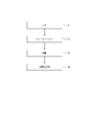
- FIG. 1 is a block diagram schematically showing a hose body mounting support system 1 according to an embodiment of the present invention.
- FIG. 2 shows an example of the machine 4'.
- the hose body attachment support system 1 is configured to support the attachment of the hose body 2'to the machine body 3'in the machine 4'.
- the user of the hose body attachment support system 1 may be, for example, the manufacturer of the hose body 2'.
- the manufacturer of the hose body 2' has, for example, when the hose body 2'is newly attached to the machine body 3', or when the hose body 2'already attached to the machine body 3'has a problem.
- the hose body attachment support system 1 can be used to suggest the proper attachment of the hose body 2'to the 3'to the manufacturer of the machine 4'.
- the machine 4' (FIG. 2) is powered by fluid pressure (eg, hydraulic) and is, for example, a construction machine (eg, hydraulic excavator, wheel loader, etc.) or factory equipment (eg, injection molding machine, die casting machine, etc.). Etc.) etc.
- the machine 4' is configured as a construction machine.
- the machine 4' includes a machine 3'and one or more hose bodies 2'.
- the machine 4' is formed by attaching one or more of these hose bodies 2'to the machine body 3'.
- the hose body 2' is configured to transmit a fluid (eg, oil) and thereby conduct a force of fluid pressure.
- the hose body 2' has a hose 21'and a pair of metal fittings 221' and 222' connected to both ends of the hose 21'.
- first metal fitting 221' one is referred to as “first metal fitting 221'” and the other is referred to as “second metal fitting 222'”.
- second metal fitting 222' the end portion 2a'on the first metal fitting 221'side is referred to as the "first end portion 2a'"
- the end portion 2a'on the second metal fitting 222'side is referred to as a "second end 2b'".
- the first end portion 2a'of the hose body 2' is the end portion of the first metal fitting 221'on the opposite side of the hose 21'.
- the second end 2b'of the hose body 2' is the end of the second metal fitting 222'on the opposite side of the hose 21'.
- the first metal fitting 221'and the second metal fitting 222' are attached to the machine body 3', respectively.
- the hose 21' includes, for example, at least one or more rubber layers and / or one or more resin layers.
- the hose 21' may further include one or more metal layers and / or one or more fiber layers.
- the hose 21' has elasticity and flexibility.
- the metal fittings 221'and 222' are formed in a tubular shape.
- the first metal fitting 221'and the second metal fitting 222' include, for example, a tubular mouth metal fitting.
- the first metal fitting 221'and the second metal fitting 222' may include a tubular adapter in addition to the mouth fitting.
- the first metal fitting 221'and the second metal fitting 222' have, for example, a screw (male screw or female screw), and the screw is tightened with respect to a screw provided on the machine body 3'to form a machine body. It may be attached to 3'.
- the first metal fitting 221'and the second metal fitting 222' may be attached to the machine body 3'by a method other than tightening the screws.
- the first metal fitting 221'and the second metal fitting 222' may be configured in any shape, for example, may be configured in an I-shape extending linearly, or bent in the middle of the extending. It may be configured in an L shape having a bent portion.
- the first metal fitting 221'and the second metal fitting 222' may have the same configuration as each other, or may have different configurations from each other. Note that FIG. 2 is only an example of the machine 4', and the machine 4'may have a different configuration from that of FIG.
- the hose body attachment support system 1 includes a processing unit 11, a storage unit 12, an input unit 13, and an output unit 14.
- the hose body attachment support system 1 may be composed of one device (for example, a personal computer, a server, a tablet, etc.), or may be composed of a plurality of devices.
- the processing unit 11 is configured to control the entire hose body attachment support system 1 including the storage unit 12, the input unit 13, and the output unit 14 by executing the program P stored in the storage unit 12. ing. The specific processing of the processing unit 11 will be described later.
- the processing unit 11 includes one or a plurality of processors such as a CPU (Central Processing Unit), for example.
- the communication between the processing unit 11 and each of the storage unit 12, the input unit 13, and the output unit 14 may be wired communication or wireless communication.
- the storage unit 12 stores the program P executed by the processing unit 11, various information used for the processing performed by the processing unit 11, and the like.
- the storage unit 12 is composed of, for example, one or a plurality of ROMs, one or a plurality of RAMs, and the like. Further, the storage unit 12 may be composed of an external storage device such as a memory card (USB or the like). Further, the storage unit 12 may be the internal memory of the processor constituting the processing unit 11.
- the program P stored in the storage unit 12 includes, for example, a simulation program PS and a support program PA. The processing unit 11 performs the simulation process described later by executing the simulation program PS.
- the processing unit 11 By executing the support program PA, the processing unit 11 performs various processes other than the simulation process (for example, input process, determination process, and post-determination process described later). However, the processing unit 11 may perform processing other than the simulation processing (for example, input processing, determination processing, and post-judgment processing described later) by executing the simulation program PS.
- the simulation process for example, input process, determination process, and post-determination process described later.
- the processing unit 11 may perform processing other than the simulation processing (for example, input processing, determination processing, and post-judgment processing described later) by executing the simulation program PS.
- the input unit 13 is composed of, for example, a keyboard, a mouse, and / or a push button, and receives input from a user.
- the output unit 14 is configured to output various information such as information input by the input unit 13 and information stored by the storage unit 12 as a result of processing by the processing unit 11.
- the output unit 14 has a display unit 141 configured to display characters, images, moving images, and the like.
- the display unit 141 is composed of, for example, a display, a monitor, or the like.
- a touch panel may be configured by the display unit 141 and the input unit 13.
- the output unit 14 may have an audio output unit configured to output audio.
- the audio output unit is composed of, for example, a speaker or the like.
- the output unit 14 may have a printing unit configured to print on a medium such as paper.
- the printing unit is composed of, for example, a printer or the like.
- the hose body attachment support method according to various embodiments of the present invention supports the attachment of the hose body 2'to the machine body 3'in the machine 4'(FIG. 2) in which the hose body 2'is attached to the machine body 3'.
- the hose body attachment support system 1 according to the above-described embodiment of the present invention is used.
- the hose body attachment support method according to each embodiment of the present invention can include an input step S1, a simulation step S2, a determination step S3, and a determination post-processing step S4.
- the processing unit 11 inputs input information to the simulation program PS and performs an input process for constructing a simulation model M (for example, FIG. 5).
- the simulation model M includes at least one or a plurality of hose body models 2 imitating the hose body 2'.
- the simulation model M may further include one or a plurality of aircraft models 3 that imitate a part of the aircraft 3'.
- the input information includes hose body mounting information and hose body movable range information.
- the hose body attachment information is information regarding attachment of the hose body 2'to the machine body 3'.
- the hose body movable range information is information regarding the movable range of both ends 2a'and 2b' of the hose body 2'during the operation of the machine body 3'.
- the processing unit 11 may input the input information according to the operation of the input unit 13 by the user, or may automatically input the input information without the operation of the input unit 13.
- the processing unit 11 performs the input step S1 by executing the support program PA or the simulation program PS (FIG. 1).
- the processing unit 11 uses the simulation model M (and at least the hose body model 2) based on the input information input in the input step S1 to use the hose body 2'while the machine body 3'is in operation. Performs simulation processing that continuously simulates the behavior of.
- the processing unit 11 performs the simulation step S2 by executing the simulation program PS (FIG. 1).
- the processing unit 11 may perform simulation processing using a known simulation technique such as finite element analysis (FEA).
- FEA finite element analysis
- the processing unit 11 determines (a) twist determination, (b) hose contact determination, (c) airframe contact determination, and (d) bending determination based on the results of simulation step S2 (and thus simulation processing). A judgment process is performed in which at least one of (e) reversal judgment and (f) mouth judgment is performed.
- the processing unit 11 determines whether or not there is an abnormality based on whether or not the predetermined hose body portion of the hose body 2'is excessively twisted. The twist determination will be described later with reference to FIGS. 4 to 8.
- the processing unit 11 determines whether or not there is an abnormality based on whether or not the hoses 21'of the plurality of hose bodies 2'are in contact with each other. The hose contact determination will be described later with reference to FIGS. 9 to 10.
- the processing unit 11 determines whether or not there is an abnormality based on whether or not the hose 21'of the hose body 2'is in contact with the airframe 3'. The aircraft contact determination will be described later, although not shown.
- the processing unit 11 determines whether or not there is an abnormality based on whether or not the hose 21'of the hose body 2'is excessively bent. The bending determination will be described later with reference to FIGS. 11 to 12.
- the processing unit 11 determines whether or not there is an abnormality based on whether or not the hose 21'of the hose body 2'is inverted. The inversion determination will be described later with reference to FIGS. 13 to 14.
- the processing unit 11 determines whether or not there is an abnormality based on whether or not the mouth portion of the hose 21'of the hose body 2'is excessively deformed. The mouth judgment will be described later with reference to FIGS. 15 to 16.
- the processing unit 11 may perform the determination step S3 by executing the support program PA (FIG. 1), or may perform the determination step S3 by executing the simulation program PS (FIG. 1). good.
- the processing unit 11 performs various processes based on the result of the determination step S3 (and thus the determination process) after the determination step S3 (and thus the determination process). For example, in the post-determination processing step S4, the processing unit 11 may perform alarm output processing, hose body attachment information change processing, hose body attachment information output processing, and the like, which will be described later.
- the processing unit 11 may perform the post-determination processing step S4 by executing the support program PA (FIG. 1), or may perform the post-determination processing step S4 by executing the simulation program PS (FIG. 1). May be done.
- the processing unit 11 makes a twist determination in the determination step S3 (and by extension, the determination process).
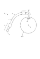
- FIG. 4 shows an image of a part of the machine 4'that is the target of the simulation in the simulation step S2 (and thus the simulation process) in this example.
- the machine 4' may be, for example, a construction machine (for example, a hydraulic excavator, a wheel loader, etc.) or a factory facility (for example, an injection molding machine, a die casting machine, etc.).
- the configuration of the machine 4'shown in FIG. 4 is only an example, and the twist determination may be performed on any part of the machine 4'with an arbitrary configuration. In the example of FIG.
- the first metal fitting 221'of the hose body 2' is attached to the portion of the machine body 3'that is fixed to the main body of the machine body 3', and the second metal fitting of the hose body 2'
- the 222' is attached to a rotating portion 32'that rotates with respect to the main body of the machine 3'of the machine 3'.
- the central axis of the rotating portion 32' is the rotating axis 3c'of the rotating portion 32'.
- the rotation axis 3c'of the rotating portion 32' is fixed to the main body of the machine body 3'.
- the first end 2a'of the hose body 2' is fixed in position with respect to the main body of the machine 3'and does not move, whereas the second end 2b of the hose body 2''Is integrated with the rotating portion 32' of the machine body 3'and rotates around the rotation axis 3c' with respect to the main body of the machine body 3'.
- the processing unit 11 inputs the input information to the simulation program PS to construct the simulation model M, and performs the input processing.
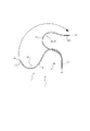
- the simulation model M shown by the solid line in FIG. 5 is constructed by inputting the input information.
- the simulation model M shown by the solid line in FIG. 5 is in the initial state SS.
- the simulation model M of FIG. 5 imitates the hose body 2'and a part of the machine body 3'(specifically, the rotating portion 32') shown in FIG.
- the simulation model M of this example is a hose body model 2 that imitates the hose body 2'shown in FIG. 4 and a machine body that imitates a part (specifically, the rotating portion 32') of the machine body 3'shown in FIG.
- the hose body model 2 has a hose portion 21 and a pair of metal fitting portions 221 and 222 connected to both ends of the hose portion 21. Of the pair of metal fittings portions 221 and 222, one is the first metal fitting portion 221 and the other is the second metal fitting portion 222.
- the hose portion 21 is a portion of the hose body 2'that imitates the hose 21'.
- the first metal fitting portion 221 and the second metal fitting portion 222 are portions that imitate the first metal fitting portion 221'and the second metal fitting 222'of the hose body 2', respectively.
- the end portion 2a on the first metal fitting portion 221 side is the first end portion 2a
- the end portion 2b on the second metal fitting portion 222 side is the second end portion 2b.
- the first end 2a and the second end 2b of the hose body model 2 correspond to the first end 2a'and the second end 2b' of the hose body 2', respectively.
- the hose body model 2 may have a solid rod shape or a hollow tubular shape.
- the airframe model 3 has a rotating portion 32.
- the rotating portion 32 is a portion that imitates the rotating portion 32'of the machine body 3'.
- the input information input in the input step S1 includes at least the hose body attachment information and the hose body movable range information.
- the input information input in the input step S1 further includes the machine information.
- the hose body attachment information is information regarding attachment of the hose body 2'to the machine body 3'.
- the hose body mounting information is used for constructing the hose body model 2.
- the hose body mounting information includes the initial position information of the hose body regarding the initial positions (positions in the initial state) of both ends 2a'and 2b' of the hose body 2', and the initial orientations of both ends 2a' and 2b'of the hose body 2'.
- Initial orientation information of the hose body regarding (orientation in the initial state) hose rigidity information regarding the rigidity of the hose 21'of the hose body 2', hose dimension information regarding the dimensions of the hose 21'of the hose body 2', and hose body 2'.
- the processing unit 11 has an initial position (position in the initial state SS) and an initial orientation (position in the initial state SS) of both end portions 2a and 2b of the hose body model 2 based on the hose body initial position information and the hose body initial orientation information. Orientation) is set.
- the processing unit 11 sets the rigidity of the hose unit 21 of the hose body model 2 based on the hose rigidity information.
- the "rigidity" is specifically bending rigidity.
- the rigidity of the hose portion 21 is set uniformly, for example, over the entire hose portion 21.
- the processing unit 11 sets the dimensions of the hose unit 21 of the hose body model 2 based on the hose dimension information. It is preferable that the hose dimensional information includes at least the hose length information regarding the length of the hose 21'. In that case, the processing unit 11 sets the length of the hose unit 21 of the hose body model 2 based on the hose length information.
- the hose dimension information may include hose outer diameter information regarding the outer diameter of the hose 21'. In that case, the processing unit 11 sets the outer diameter of the hose portion 21 of the hose body model 2 based on the hose outer diameter information.
- the processing unit 11 sets the shape and dimensions of the metal fittings 221 and 222 of the hose body model 2 based on the metal fitting information.
- the metal fitting information includes at least the metal fitting shape information regarding the shape of the metal fittings 221' and 222'and the metal fitting dimensional information regarding the dimensions of the metal fittings 221' and 222'.
- the processing unit 11 sets the shape and dimensions of the metal fittings 221 and 222 of the hose body model 2 based on the metal fitting shape information and the metal fitting dimension information.
- the metal fitting shape information is information that specifies, for example, whether the metal fittings 221', 222'are I-shaped or L-shaped, and if the metal fittings are L-shaped, the bending angle of the bent portion and the like.
- the first metal fitting 221'of the hose body 2'and the first metal fitting portion 221 of the hose body model 2 are I-shaped, and the second metal fitting 222' of the hose body 2', and thus the hose body model.
- the second metal fitting portion 222 of No. 2 is L-shaped.
- the metal fitting dimension information specifies, for example, the length of the metal fitting 221', 222'(for example, the total length and / or, in the case of an L-shape, the length between the bent portion and the end portion, etc.).
- the metal fitting information may include metal fitting rigidity information regarding the rigidity of the metal fittings 221', 222'.
- the processing unit 11 sets the rigidity of the metal fittings 221 and 222 of the hose body model 2 based on the metal fitting rigidity information.
- the stiffness specified by the metal fitting stiffness information is higher than the stiffness specified by the hose stiffness information.
- the aircraft information is information about a predetermined portion of the aircraft 3'(specifically, in this example, the rotating portion 32').
- the aircraft information is used for constructing an aircraft model 3 that imitates the predetermined portion of the aircraft 3'.
- the aircraft information includes aircraft shape information regarding the shape of the predetermined portion of the aircraft 3', aircraft initial position information regarding the initial position (position in the initial state) of the predetermined portion of the aircraft 3', and initial of the predetermined portion of the aircraft 3'. It is preferable to include information on the initial orientation of the aircraft regarding the orientation (orientation in the initial state).
- the processing unit 11 has the shape, initial position (position in the initial state SS), and initial orientation (in the initial state SS) of the machine model 3 based on the machine shape information, the machine initial position information, and the machine initial orientation information. Orientation) is set respectively.
- the airframe information may include airframe rigidity information regarding the rigidity of the predetermined portion of the airframe 3'. In that case, the processing unit 11 sets the rigidity of the aircraft model 3 based on the aircraft rigidity information.
- the stiffness specified by the airframe stiffness information is higher than the stiffness specified by the hose stiffness information.
- the airframe information further includes the airframe movable range information.
- the aircraft movable range information is information regarding the movable range of the predetermined portion of the aircraft 3', and specifically, how much the predetermined portion of the aircraft 3'is from the initial state during the operation of the aircraft 3'. It is information that identifies whether it works.
- the processing unit 11 sets the movable range of the aircraft model 3 based on the aircraft movable range information, and specifically, sets how and how the aircraft model 3 moves from the initial state SS.
- the rotating portion 32 is rotated by a predetermined angle from the initial state SS around the rotation axis 3c in the circumferential direction (clockwise in FIG. 5) by a predetermined angle (broken line in FIG. 5).
- the rotation axis 3c is rotated in the other side in the circumferential direction (counterclockwise in FIG. 5) by a predetermined angle to return to the initial state SS.
- the aircraft information does not have to include the aircraft movable range information, that is, the aircraft model 3 may be set so as not to move and to be fixed.
- the input information may not include the aircraft information, that is, the simulation model M may not include the aircraft model 3.
- the hose body movable range information is information regarding the movable range of both end portions 2a'and 2b' of the hose body 2'while the machine body 3'is in operation, and specifically, both end portions 2a'of the hose body 2'. 2b'is information for specifying how much and how it moves from the initial state during the operation of the aircraft 3'.
- the processing unit 11 sets the movable range of both end portions 2a and 2b of the hose body model 2 based on the hose body movable range information, and specifically, both end portions 2a and 2b of the hose body model 2 are in the initial state. Set how much and how it moves from the SS. In the example of FIG.
- the hose body movable range information is fixed so that the first end portion 2a does not move, and the second end portion 2b is integrated with the rotating portion 32 of the machine model 3 from the initial state SS.
- the state of the simulation model M when the simulation model M moves to the maximum from the initial state SS is referred to as "maximum degree state SM", and the simulation when the movement of the simulation model M ends.
- the state of the model M is called "final state SF".
- the maximum degree state SM of the simulation model M corresponds to the states of the hose body 2'and the machine body 3'when the machine body 3'moves to the maximum from the initial state.
- the final state SF may be the same as the initial state SS, may be the same as the maximum state SM, or may be different from both the initial state SS and the maximum state SM.
- the second end portion 2b of the hose body model 2 and the rotating portion 32 of the machine body model 3 are on one side in the circumferential direction around the rotation axis 3c from the initial state SS (clockwise in FIG. 5).
- the final state SF is the maximum degree of the second end portion 2b of the hose body model 2 and the rotating portion 32 of the machine body model 3. It is the state of the simulation model M when it is rotated by a predetermined angle from the state SM to the other side in the circumferential direction (counterclockwise in FIG.
- the operation of the simulation model M when the simulation model M moves from the initial state SS to the maximum degree state SM is referred to as "outward operation", and the simulation model M is finally from the maximum degree state SM.
- the operation of the simulation model M when moving to the state SF is called "return operation".
- the simulation model M performs only the forward operation and does not perform the return operation.
- the processing unit 11 bases the simulation model M (in this example, the hose body model 2 and the machine body model 3) based on the input information input in the input step S1. ) Is used to continuously simulate the behavior of the hose body 2'during the operation of the machine body 3'. In the simulation process, the processing unit 11 calculates the shape of the hose unit 21 of the hose body model 2 in the initial state SS based on the hose body attachment information in the input information, and also calculates the hose body attachment information and the hose body in the input information.
- the simulation model M in this example, the hose body model 2 and the machine body model 3
- the state of the hose body model 2 (the orientation of the metal fittings 221, 222, the shape of the hose 21, etc.) at each predetermined time after the initial state SS is calculated.
- the machine model 3 may be made to move according to the machine information in the input information during the simulation (in that case, the processing unit 11 behaves as the machine model 3).
- the processing unit 11 may simulate the behavior of the machine model 3 based on the machine information.
- the processing unit 11 After the simulation step S2, in the determination step S3, the processing unit 11 performs a determination process based on the result of the simulation step S2 (and thus the simulation process). In the present embodiment, the processing unit 11 makes a twist determination in the determination process. In the twist determination, the processing unit 11 determines whether or not there is an abnormality based on whether or not the predetermined hose body portion of the hose body 2'is excessively twisted. In this example, the predetermined hose body portion is the second end portion 2b'of the hose body 2'.
- the processing unit 11 determines that the predetermined hose body portion of the hose body 2'is excessively twisted, it is determined that there is an abnormality, and on the other hand, it is determined that the predetermined hose body portion of the hose body 2'is not excessively twisted. If so, it is judged that there is no abnormality.
- the predetermined hose body part to be determined for twisting even if it is a part or all of the metal fitting 221'or 222' (in this example, the end portion 2b'of the second metal fitting 222') as in this example. It may be a part or all of the hose portion 21, or it may be the whole of the hose body 2.
- the connection between the metal fitting 221'or 222'and the machine body 3' may be loosened, and thus fluid leakage may occur.
- the predetermined hose body portion to be determined for twisting is a part or all of the metal fittings 221'or 222' (in this example, the end portion 2b of the second metal fittings 222') as in this example, the machine 4 It is possible to avoid attaching the hose body 2'to the machine body 3', which causes loosening of the connection between the metal fitting 221' or 222' and the machine body 3'during the use of the hose body 2'. Further, if the hose 21'is excessively twisted, the hose 21'may be damaged.
- the hose body 2' When the predetermined hose body part to be determined for twisting is a part or all of the hose part 21, the hose body 2'has a body 3'that causes damage to the hose 21'during the use of the machine 4'. It is possible to avoid mounting on the hose.
- the processing unit 11 determines the twist, and based on the result of the simulation processing, at any time during the operation of the machine body 3', the above-mentioned predetermined hose body portion of the hose body 2'(in this example, the second).
- a torque determination may be made to determine whether or not the predetermined hose body portion is excessively twisted based on whether or not the torque at the end portion 2b') exceeds the predetermined torque threshold value.
- the torque may be defined to be positive (+) or negative ( ⁇ ) depending on the direction, or may be defined to be always positive (+) regardless of the direction. In the former case, in the comparison with the predetermined torque threshold value, the absolute value of the torque and the predetermined torque threshold value shall be compared. This will be described with reference to FIG.
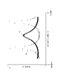
- the solid line indicates the predetermined hose body model portion (in this example, the second end portion) corresponding to the predetermined hose body portion of the hose body model 2 in the simulation using the simulation model M of the example of FIG.
- the torque (exponential value) acting on 2b) is shown.
- the horizontal axis is the time (seconds) during operation of the simulation model M
- the vertical axis is the predetermined hose body model portion (specifically, the second end portion 2b) of the hose body model 2. ) Is the torque (exponential value) acting on.
- the torque is defined to be positive (+) or negative ( ⁇ ) depending on the orientation.
- the processing unit 11 is attached to the predetermined hose body model portion of the hose body model 2 at each time of each predetermined time during the operation of the simulation model M in the simulation of the simulation step S2 (and by extension, the operation of the machine body 3'). Calculate the acting torque (exponential value) respectively. The calculation of this torque may be performed in the simulation step S2 or in the determination step S3. Then, in the torque determination in the determination step S3, the processing unit 11 determines the torque (specifically, in this example, the absolute value of the torque) and the predetermined torque threshold value Tt (specifically, in this example) at each time during the operation of the simulation model M.
- the processing unit 11 When it is determined that the torque in the predetermined hose body model portion of the hose body model 2 exceeds the predetermined torque threshold Tt at any time during the operation of the simulation model M as a result of comparison with 6). At any time during the operation of the machine 3', it is determined that the predetermined hose model part and thus the predetermined hose body part are excessively twisted, while in other cases, any of the parts during the operation of the machine 3'. Even at the time, it is determined that the predetermined hose body model portion and thus the predetermined hose body portion are not excessively twisted.
- the processing unit 11 operates the simulation model M.
- the predetermined hose body model part and thus the predetermined hose body part are excessively twisted, while in other cases, at any time during the operation of the machine 3', the predetermined hose body It is judged that the model part and the predetermined hose body part are not excessively twisted.
- the absolute value of the torque of the predetermined hose body model portion exceeds the predetermined torque threshold value Tt at a plurality of times during the operation of the simulation model M. Therefore, in the torque determination, in the simulation using the simulation model M of FIG.
- the processing unit 11 has the predetermined hose body model portion (second end portion 2b) and thus at the plurality of times during the operation of the machine body 3'. It is determined that the predetermined hose body portion (second end portion 2b') is excessively twisted. Therefore, it can be seen that the mounting structure (FIG. 4) of the hose body 2'corresponding to the simulation model M in the example of FIG. 5 to the machine body 3'is not appropriate.
- the processing unit 11 determines the twist, and based on the result of the simulation processing, at any time during the operation of the machine 3', the predetermined hose body portion of the hose body 2'(in this example, the second end).
- a twist amount determination may be made to determine whether or not the predetermined hose body portion is excessively twisted based on whether or not the twist amount in the portion 2b') exceeds the predetermined twist amount threshold.
- the twist amount may be defined to be positive (+) or negative ( ⁇ ) depending on the direction, or may be defined to always be positive (+) regardless of the direction. In the former case, in the comparison with the predetermined twist amount threshold value, the absolute value of the twist amount and the predetermined twist amount threshold value shall be compared.
- the processing unit 11 corresponds to the predetermined hose body portion of the hose body model 2 at each time of each predetermined time during the operation of the simulation model M in the simulation of the simulation step S2 (and by extension, the operation of the machine body 3').
- the amount of twist acting on the predetermined hose body model portion (in this example, the second end portion 2b) is calculated.
- the calculation of the twist amount may be performed in the simulation step S2 or in the determination step S3.
- the processing unit 11 compares the twist amount at each time during the operation of the simulation model M with the predetermined twist amount threshold, and as a result, the simulation model M is in operation.
- the processing unit 11 is the simulation model M.
- predetermined hose body model part and thus the predetermined hose body part are excessively twisted at any time in the above, while in other cases, at any time during the operation of the machine 3', the above is described. It is determined that the predetermined hose body model portion and thus the predetermined hose body portion are not excessively twisted.
- the processing unit 11 determines the twist, and based on the result of the simulation processing, at any time during the operation of the machine body 3', the predetermined hose body portion of the hose body 2'(in this example, the second end).
- Rotation that determines whether or not the predetermined hose body portion is excessively twisted based on whether or not the rotation angle of the hose body 2'around the central axis in the portion 2b') exceeds the predetermined rotation angle threshold value. You may judge the angle.
- the rotation angle may be defined to be positive (+) or negative ( ⁇ ) depending on the orientation, or may be defined to be always positive (+) regardless of the orientation.
- the processing unit 11 corresponds to the predetermined hose body portion of the hose body model 2 at each time of each predetermined time during the operation of the simulation model M in the simulation of the simulation step S2 (and by extension, the operation of the machine body 3').
- the rotation angle around the central axis of the hose body model 2 acting on the predetermined hose body model portion (in this example, the second end portion 2b) is calculated.
- the calculation of the rotation angle may be performed in the simulation step S2 or in the determination step S3.
- the processing unit 11 compares the rotation angle at each time during the operation of the simulation model M with the predetermined rotation angle threshold, and as a result, the simulation model M is in operation.
- the rotation angle of the hose body model 2 in the predetermined hose body model portion exceeds the predetermined rotation angle threshold value at any time in the above-mentioned predetermined time, at any time during the operation of the machine body 3'. It is determined that the hose body model part and thus the predetermined hose body part are excessively twisted, while in other cases, the predetermined hose body model part and thus the predetermined hose body part are performed at any time during the operation of the machine body 3'. Judges that it was not twisted excessively.
- the processing unit 11 is the simulation model M.
- Rotation that acts at each position at predetermined intervals along the extending direction of the predetermined hose body model portion of the hose body model 2 at each predetermined time during operation (and by extension, during operation of the aircraft 3'). Calculate the angles (exponential values) respectively. Then, in the rotation angle determination in the determination step S3, the rotation angle at each position of the predetermined hose body model portion at each time during the operation of the simulation model M is compared with the predetermined rotation angle threshold, and as a result, the result is obtained.
- the operation of the machine body 3' is performed. It is determined that the predetermined hose body model part and thus the predetermined hose body part are excessively twisted at any time in the above, while in other cases, at any time during the operation of the machine 3', the above is described. It is determined that the predetermined hose body model portion and thus the predetermined hose body portion are not excessively twisted.
- the processing unit 11 may make any plurality of determinations among the above-mentioned torque determination, twist amount determination, and rotation angle determination. In that case, the processing unit 11 determines that there is an abnormality when it is determined in each of the plurality of determinations that the predetermined hose body portion is excessively twisted, and in other cases, it is determined that there is no abnormality. You may. Alternatively, in the twist determination, the processing unit 11 determines that there is an abnormality when it is determined that the predetermined hose body portion is excessively twisted in at least one of the plurality of determinations, and in other cases, there is no abnormality. You may judge that.
- the processing unit 11 performs various processes based on the result of the determination step S3 (and thus the determination process) after the determination step S3 (and thus the determination process).
- the alarm output step causes the output unit 14 (FIG. 1) to output an alarm in the post-determination processing step S4.
- the processing unit 11 may, for example, display an alarm on the display unit 141 (FIG. 1) and / or have the audio output unit output the alarm by voice and /.
- the printing unit may print the alarm.
- the user can know that the hose body 2'that is the target of the simulation in the simulation step S2 is not properly attached to the machine body 3', and thus avoids such attachment. be able to.
- the processing unit 11 determines that there is an abnormality in the determination step S3 (and by extension, the determination process)
- the hose body attachment information for example, hose body initial position information, hose body initial orientation information, hose rigidity information
- the hose body mounting information change step (and thus the hose body mounting information change processing) may be performed.
- the processing unit 11 includes the hose body attachment information changed in the hose body attachment information change step (and by extension, the hose body attachment information change process) after the hose body attachment information change step (and by extension, the hose body attachment information change process).
- the simulation step S2 (and by extension, the simulation process) is performed again.
- the information other than the hose body mounting information changed in the hose body mounting information change step (and by extension, the hose body mounting information change process) is used in the previous simulation step S2 (and by extension, the simulation process).
- the simulation process Use the same information that you received.
- the hose body mounting information is changed and the simulation is performed again, so that the simulation can be repeated until it is determined that there is no abnormality in the determination step S3.
- the processing unit 11 includes information other than the hose body initial position information (for example, hose body initial orientation information, hose rigidity information, hose dimension information, and metal fitting information) among the hose body mounting information. It is preferable to change at least a part of them). This is because it may be difficult to actually change the positions of both ends 2a and 2b of the hose body 2'.
- FIG. 7 shows the hose body mounting information input to the simulation model M of the example of FIG. 5 in the input step S1 (and thus the input processing) through the hose body mounting information change step (and thus the hose body mounting information change processing).
- the image of the simulation model M in which the hose body mounting information different from that of the above is input is shown.
- the simulation model M of the example of FIG. 7 has the orientation of the second end 2b of the hose body model 2 set by the initial orientation information of the hose body and the hose length of the hose dimension information with respect to the simulation model M of the example of FIG. Only the length of the hose portion 21 set by the information and the lengths of the metal fittings 221 and 222 set by the metal fitting dimension information of the metal fitting information are different.
- FIG. 8 shows an image of the mounting structure of the hose body 2'to the machine body 3', which corresponds to the simulation model M of the example of FIG. 7.
- the broken line indicates the predetermined hose body model portion corresponding to the predetermined hose body portion of the hose body model 2 in the simulation using the simulation model M of the example of FIG. 7 (in this example, the second end portion).
- the torque (exponential value) acting on 2b) is shown.
- the torque shown by the broken line in FIG. 6 is equal to or less than the predetermined torque threshold Tt at all times during the operation of the simulation model M, and the hose body 2'corresponding to the simulation model M in the example of FIG. 7 is attached to the machine body 3'. It can be seen that the structure (FIG. 8) is appropriate.
- the processing unit 11 determines that there is no abnormality in the determination step S3 (and by extension, the determination process)
- the processing unit 11 outputs the hose body mounting information used in the simulation step S2 (and thus the simulation process) to the output unit 14 in the post-determination processing step S4.
- the hose body mounting information output step (and thus the hose body mounting information output processing) may be performed.
- the processing unit 11 may display the hose body mounting information on the display unit 141 (FIG. 1), and / or the voice output unit may display the hose body mounting information by voice. It may be output, and / or the hose body mounting information may be printed on the printing unit.
- the user can grasp an appropriate mounting structure (FIG. 8) of the hose body 2'to the machine body 3'.
- the processing unit 11 makes a hose contact determination in the determination step S3 (and thus the determination process).
- the illustration of the machine 4' which is the target of the simulation in the simulation step S2 (and thus the simulation process) is omitted.
- the machine 4' may be, for example, a construction machine (for example, a hydraulic excavator, a wheel loader, etc.) or a factory facility (for example, an injection molding machine, a die casting machine, etc.).
- the input step S1 (and thus the input process) and the simulation step S2 (and thus the simulation process) are performed in the same manner as in the first embodiment.
- 9 to 10 show an image of how the simulation model M operates in the simulation in the simulation step S2 (and thus the simulation process) in this example.
- the simulation model M shown in FIG. 9A is constructed by inputting the input information in the input step S1 (and by extension, the input process).
- the simulation model M is in the initial state SS.
- the simulation model M has a plurality of hose body models 2 that imitate each of the plurality of hose bodies 2', and a machine body model 3 that imitates a part of the machine body 3'.
- the input information input in the input step S1 is at least the hose body attachment information of each of the plurality of hose bodies 2'and the respective end portions 2a and 2b of the plurality of hose bodies 2'in operation of the machine body 3'. Includes hose body movable range information regarding the movable range of.
- the input information input in the input step S1 further includes the machine information.
- the airframe information does not include the airframe movable range information, that is, the airframe model 3 is fixed without moving.
- the airframe model 3 has a cylindrical shape.
- the airframe information may include the airframe movable range information, that is, the airframe model 3 may be set to move.
- the input information may not include the aircraft information, that is, the simulation model M may not include the aircraft model 3.
- the hose body movable range information is fixed so that the second end portion 2b of each hose body model 2 does not move, and the first end portion 2a of each hose body model 2 is integrated with each other. Then, from the initial state SS (FIG. 9 (a)), the rotation is performed by a predetermined angle on one side in the circumferential direction (clockwise in FIGS. 9 to 10) around the rotation axis 3c (FIG. 9 (b), FIG. 10 (a), FIG. 10 (b)), the maximum degree state SM (FIG.
- the rotation axis 3c is a cylindrical central axis formed by the machine model 3.
- the processing unit 11 has a plurality of hose bodies that imitate the simulation model M (in this example, the plurality of hose bodies 2', respectively, based on the input information input in the input step S1.
- the processing unit 11 uses the model 2 and the machine model 3 to calculate the behavior of each of the plurality of hose bodies 2'during the operation of the machine 3'is continuously simulated.
- the processing unit 11 calculates the shape of the hose unit 21 of each hose body model 2 in the initial state SS based on the hose body attachment information in the input information, and also calculates the hose body attachment information and the hose in the input information.
- the state of each hose body model 2 (direction of metal fittings 221, 222, shape of hose 21, etc.) at each time at predetermined time after the initial state SS is calculated.
- the simulation model M includes the machine model 3 and the machine model 3 is set to move
- the machine model 3 may be made to move according to the machine information in the input information during the simulation (its).
- the processing unit 11 does not simulate the behavior of the aircraft model 3), or the processing unit 11 may simulate the behavior of the aircraft model 3 based on the aircraft information.
- the processing unit 11 performs the determination process based on the result of the simulation step S2 (and by extension, the simulation process).
- the processing unit 11 makes a hose contact determination in the determination process.
- the processing unit 11 determines whether or not there is an abnormality based on whether or not the hoses 21'of the plurality of hose bodies 2'are in contact with each other.
- the processing unit 11 determines that the hoses 21'of the plurality of hose bodies 2'are in contact with each other (specifically, the hoses 21' of at least one pair of hose bodies 2'are in contact with each other), it is abnormal.
- the hoses 21'of the plurality of hose bodies 2' were not in contact with each other (specifically, the hoses 21' of any pair of hose bodies 2'were not in contact with each other). If so, it is judged that there is no abnormality. If the hoses 21'of the plurality of hose bodies 2'come into contact with each other, the hoses 21'may be damaged. According to the hose contact determination, it is possible to avoid attaching the hose body 2'to the machine body 3', which causes damage to the hose 21'during the use of the machine 4'.
- the processing unit 11 acts between the hoses 21'of the plurality of hose bodies 2'at any time during the operation of the machine 3'based on the result of the simulation processing.
- a hose contact energy determination may be made in which it is determined whether or not the hoses 21'of the plurality of hose bodies 2'are in contact with each other based on whether or not the contact energy exceeds a predetermined hose contact energy threshold.
- the contact energy may be defined to be "positive (+)” or “negative (-)” depending on the direction, or may always be “positive (+)” regardless of the direction. It may be defined.
- the processing unit 11 follows the extending direction of the hose unit 21 of each hose body model 2 for each time at each predetermined time during the operation of the simulation model M (and by extension, the operation of the machine body 3').
- the contact energy acting on each position at predetermined intervals is calculated.
- the calculation of the contact energy may be performed in the simulation step S2 or in the determination step S3.
- the processing unit 11 determines the contact energy and the predetermined hose contact energy at each position of the hose unit 21 of each hose body model 2 at each time during the operation of the simulation model M.
- the contact energy in at least a part of the hose portions 21 of at least one pair of hose body models 2 at any time during the operation of the simulation model M has a predetermined hose contact energy threshold.
- the predetermined hose contact energy threshold may be set to 0 or may be set to a value greater than 0.
- the processing unit 11 acts between the hoses 21'of the plurality of hose bodies 2'at any time during the operation of the machine 3'based on the result of the simulation processing.
- a hose contact pressure determination may be made to determine whether or not the pressure exceeds a predetermined hose contact pressure threshold.
- the contact pressure may be defined to be "positive (+)” or “negative (-)” depending on the direction, or may always be “positive (+)” regardless of the direction. It may be defined. In the former case, in the comparison with the predetermined hose contact pressure threshold value, the absolute value of the contact pressure and the predetermined hose contact pressure threshold value shall be compared.
- the processing unit 11 follows the extending direction of the hose unit 21 of each hose body model 2 for each time at each predetermined time during the operation of the simulation model M (and by extension, the operation of the machine body 3').
- the contact pressure acting on each position at predetermined intervals is calculated.
- the calculation of the contact pressure may be performed in the simulation step S2 or in the determination step S3.
- the processing unit 11 determines the contact pressure and the predetermined hose contact pressure at each position of the hose unit 21 of each hose body model 2 at each time during the operation of the simulation model M.
- the contact pressure in at least a part of the hose portion 21 of at least one pair of hose body models 2 at any time during the operation of the simulation model M sets the predetermined hose contact pressure threshold value.
- the hose portions 21 of the plurality of hose body models 2 and thus the hoses 21'of the plurality of hose bodies 2') come into contact with each other at any time during the operation of the machine body 3'.
- the hose portions 21 of the plurality of hose body models 2 are connected to each other. Judges that they did not contact.
- the predetermined hose contact pressure threshold value may be set to 0 or may be set to a value larger than 0.
- the processing unit 11 makes a contact acting between the hoses 21'of the plurality of hose bodies 2'at any time during the operation of the machine 3'based on the result of the simulation processing.
- a hose contact force determination may be made to determine whether or not the force exceeds a predetermined hose contact force threshold.
- the contact force may be defined to be "positive (+)” or “negative (-)” depending on the direction, or may always be “positive (+)” regardless of the direction. It may be defined. In the former case, in the comparison with the predetermined hose contact force threshold value, the absolute value of the contact force and the predetermined hose contact force threshold value shall be compared.
- the processing unit 11 follows the extending direction of the hose unit 21 of each hose body model 2 for each time of each predetermined time during the operation of the simulation model M (and by extension, the operation of the machine body 3').
- the contact force acting on each position at predetermined intervals is calculated.
- the calculation of the contact force may be performed in the simulation step S2 or in the determination step S3.
- the processing unit 11 determines the contact force and the predetermined hose contact force threshold at each position of the hose unit 21 of each hose body model 2 at each time during the operation of the simulation model M.
- the contact force of at least a part of the hose portions 21 of at least one pair of hose body models 2 exceeds the predetermined hose contact force threshold at any time during the operation of the simulation model M. If it is determined that the hose portions 21 of the plurality of hose body models 2 (and thus the hoses 21' of the plurality of hose bodies 2') are in contact with each other at any time during the operation of the machine body 3'. On the other hand, in other cases, the hose portions 21 of the plurality of hose body models 2 (and thus the hoses 21' of the plurality of hose bodies 2') are connected to each other at any time during the operation of the machine body 3'. Judge that they did not touch.
- the predetermined hose contact force threshold may be set to 0 or may be set to a value greater than 0.
- the processing unit 11 determines the relative distance between the hoses 21'of the plurality of hose bodies 2'at any time during the operation of the machine 3'based on the result of the simulation processing. , The hose relative distance may be determined to determine whether or not it has become 0. In this case, the processing unit 11 follows the extending direction of the hose unit 21 of each hose body model 2 for each time at each predetermined time during the operation of the simulation model M (and by extension, the operation of the machine body 3'). The relative distance between each position at each predetermined interval is calculated. The calculation of this relative distance may be performed in the simulation step S2 or in the determination step S3.
- the relative distance between the above positions of the hose units 21 of each hose body model 2 at each time during the operation of the simulation model M is 0.
- the relative distance between at least a part of the hose portions 21 of at least one pair of hose body models 2 is determined.
- the hose portions 21 of the plurality of hose body models 2 (and by extension, the hoses 21'of the plurality of hose bodies 2') are used at any time during the operation of the machine body 3'. It is judged that they did not contact each other.
- the processing unit 11 may make any plurality of determinations among the above-mentioned hose contact energy determination, hose contact pressure determination, hose contact force determination, and hose relative distance determination. In that case, when the processing unit 11 determines in the hose contact determination that the hoses 21'of the plurality of hose bodies 2'are in contact with each other in each of the plurality of determinations, it is determined that there is an abnormality, and in other cases. In addition, it may be judged that there is no abnormality.
- the processing unit 11 determines that there is an abnormality, and other than that. In the case of, it may be judged that there is no abnormality.
- the post-judgment processing step S4 (and thus the post-judgment processing) is the same as that of the first embodiment.
- the processing unit 11 simulates, for example, on the display unit 141 in the simulation step S2 (and thus the simulation processing).
- the processing unit 11 simulates, for example, on the display unit 141 in the simulation step S2 (and thus the simulation processing).
- the hose portions 21 of the plurality of hose body models 2 are displayed. It may be displayed so that the parts that have come into contact with each other can be seen. For example, as shown in FIGS.
- the portion where the hose portions 21 of the plurality of hose body models 2 are in contact with each other has a different color from the other portions of the hose portion 21 (FIG. 9 (FIG. 9). It may be shown by a) and black) in FIG. 9 (b).
- the user can specifically grasp which part of the hose 21'of the plurality of hose bodies 2'is in contact with how often.
- the user can take measures such as preventing damage to the frequently contacted portion of the hose 21'of the hose body 2'by covering the portion with an exterior member.
- the processing unit 11 makes an aircraft contact determination in the determination step S3 (and by extension, the determination process).
- the machine 4' may be, for example, a construction machine (for example, a hydraulic excavator, a wheel loader, etc.) or a factory facility (for example, an injection molding machine, a die casting machine, etc.).
- the input step S1 (and thus the input process) and the simulation step S2 (and thus the simulation process) are performed in the same manner as in the first embodiment.
- the simulation model M has a hose body model 2 that imitates the hose body 2'and a machine body model 3 that imitates a part of the machine body 3'.
- the input information input in the input step S1 includes at least the hose body attachment information, the hose body movable range information, and the machine body information.
- the airframe information may include airframe movable range information, that is, the airframe model 3 may be set to move. Alternatively, the airframe information does not include the airframe movable range information, that is, the airframe model 3 may be fixed without moving.
- the processing unit 11 uses the simulation model M (in this example, the hose body model 2 and the machine body model 3) based on the input information input in the input step S1 to form the machine body.
- the hose body 2'during the operation of 3' is continuously simulated.
- the processing unit 11 calculates the shape of the hose unit 21 of the hose body model 2 in the initial state SS based on the hose body attachment information in the input information, and also calculates the hose body attachment information and the hose body in the input information.
- the state of the hose body model 2 (the orientation of the metal fittings 221, 222, the shape of the hose 21, etc.) at each predetermined time after the initial state SS is calculated.
- the machine model 3 When the machine model 3 is set to move, the machine model 3 may be made to move according to the machine information in the input information during the simulation (in that case, the processing unit 11 may be set to move according to the machine model 3).
- the behavior may not be simulated), or the processing unit 11 may simulate the behavior of the aircraft model 3 based on the aircraft information.
- the processing unit 11 performs the determination process based on the result of the simulation step S2 (and by extension, the simulation process).
- the processing unit 11 makes an aircraft contact determination in the determination process.
- the processing unit 11 determines whether or not there is an abnormality based on whether or not the hose 21'of the hose body 2'is in contact with the airframe 3'.
- the processing unit 11 determines that the hose 21'of the hose body 2'has come into contact with the machine body 3', it determines that there is an abnormality, while the hose 21'of the hose body 2'does not come into contact with the machine body 3'.
- the hose 21'of the hose body 2' comes into contact with the machine body 3', the hose 21'may be damaged. According to the airframe contact determination, it is possible to avoid attaching the hose body 2'to the airframe 3', which causes damage to the hose 21'while the machine 4'is in use.
- Airframe contact energy determination may be made to determine whether or not the hose 21'of the hose body 2'has contacted the airframe 3'based on whether or not the contact energy to be applied exceeds the predetermined airframe contact energy threshold. ..
- the contact energy may be defined to be "positive (+)” or “negative (-)” depending on the direction, or may always be “positive (+)” regardless of the direction. It may be defined.
- the processing unit 11 in the comparison with the predetermined aircraft contact energy threshold value, the absolute value of the contact energy and the predetermined aircraft contact energy threshold value shall be compared.
- the processing unit 11 extends the hose unit 21 of the hose body model 2 from the machine body 3'for each time of each predetermined time during the operation of the simulation model M (and by extension, the operation of the machine body 3').
- the contact energy acting on each position at predetermined intervals along the above is calculated.
- the calculation of the contact energy may be performed in the simulation step S2 or in the determination step S3.
- the processing unit 11 determines the contact energy and the predetermined aircraft contact energy at each position of the hose portion 21 of the hose body model 2 at each time during the operation of the simulation model M. When it is compared with the threshold value and as a result, it is determined that the contact energy in at least a part of the hose portion 21 of the hose body model 2 exceeds the predetermined machine contact energy threshold at any time during the operation of the simulation model M. In addition, it is determined that the hose 21'of the hose body 2'has come into contact with the machine body 3'at any time during the operation of the machine body 3', while in other cases, any time during the operation of the machine body 3'. It is determined that the hose 21'of the hose body 2'has not come into contact with the machine body 3'even at the time of.
- the predetermined airframe contact energy threshold value may be set to 0 or may be set to a value larger than 0.
- the processing unit 11 acts on the hose 21'of the hose body 2'from the machine 3'at any time during the operation of the machine 3'based on the result of the simulation process in the machine contact determination.
- the airframe contact pressure determination may be made to determine whether or not the hose 21'of the airframe 2'is in contact with the airframe 3'.
- the contact pressure may be defined to be "positive (+)” or “negative (-)” depending on the direction, or may always be “positive (+)” regardless of the direction. It may be defined. In the former case, in the comparison with the predetermined airframe contact pressure threshold value, the absolute value of the contact pressure and the predetermined airframe contact pressure threshold value shall be compared.
- the processing unit 11 extends the hose unit 21 of the hose body model 2 from the machine body 3'for each time of each predetermined time during the operation of the simulation model M (and by extension, the operation of the machine body 3').
- the contact pressure acting on each position at predetermined intervals along the above is calculated.
- the calculation of the contact pressure may be performed in the simulation step S2 or in the determination step S3.
- the processing unit 11 determines the contact pressure and the predetermined aircraft contact pressure at each position of the hose portion 21 of the hose body model 2 at each time during the operation of the simulation model M.
- the contact pressure in at least a part of the hose portion 21 of the hose body model 2 exceeds the predetermined body contact pressure threshold value at any time during the operation of the simulation model M.
- the hose 21'of the hose body 2' has contacted the body 3'at any time during the operation of the machine body 3', while in other cases, any time during the operation of the machine body 3'. It is determined that the hose 21'of the hose body 2'has not come into contact with the machine body 3'even at the time of.
- the predetermined airframe contact pressure threshold value may be set to 0 or may be set to a value larger than 0.
- the processing unit 11 acts on the hose 21'of the hose body 2'from the machine 3'at any time during the operation of the machine 3'based on the result of the simulation process in the machine contact determination.
- the airframe contact force determination may be made to determine whether or not the hose 21'of the hose body 2'has contacted the airframe 3'.
- the contact force may be defined to be "positive (+)” or “negative (-)” depending on the direction, or may always be "positive (+)” regardless of the direction. It may be defined. In the former case, in the comparison with the predetermined aircraft contact force threshold value, the absolute value of the contact force and the predetermined aircraft contact force threshold value shall be compared.
- the processing unit 11 extends the hose unit 21 of the hose body model 2 from the machine body 3'for each time of each predetermined time during the operation of the simulation model M (and by extension, the operation of the machine body 3').
- the contact force acting on each position at predetermined intervals along the above is calculated.
- the calculation of the contact force may be performed in the simulation step S2 or in the determination step S3.
- the processing unit 11 determines the contact force and the predetermined aircraft contact force at each position of the hose portion 21 of the hose body model 2 at each time during the operation of the simulation model M.
- the predetermined body contact force threshold value may be set to 0 or may be set to a value larger than 0.
- the processing unit 11 determines the contact between the hose body 2'and the hose 21'of the hose body 2'at any time during the operation of the machine body 3'based on the result of the simulation process. Based on whether or not the distance becomes 0, the hose 21'of the hose body 2'may determine whether or not the hose 21'has contacted the machine body 3', and the machine body relative distance determination may be performed. In this case, the processing unit 11 determines each time of each predetermined time during the operation of the simulation model M (and by extension, the operation of the machine body 3') along the extending direction of the hose part 21 of the hose body model 2. The relative distance between each position at each interval and the aircraft model 3 is calculated.
- the calculation of this relative distance may be performed in the simulation step S2 or in the determination step S3. Then, in the determination of the relative distance between the aircraft in the determination step S3, the processing unit 11 determines the relative distance between each position of the hose portion 21 of the hose model 2 and the aircraft model 3 at each time during the operation of the simulation model M. It is determined whether or not the distance is 0, and as a result, at any time during the operation of the simulation model M, the relative distance between at least a part of the hose portion 21 of the hose body model 2 and the machine body model 3. However, when it is determined that the value becomes 0, it is determined that the hose 21'of the hose body 2'has contacted the aircraft 3'at any time during the operation of the aircraft 3', while in other cases. It is determined that the hose 21'of the hose body 2'has not come into contact with the machine body 3'at any time during the operation of the machine body 3'.
- the processing unit 11 may make any plurality of determinations among the above-mentioned airframe contact energy determination, airframe contact pressure determination, airframe contact force determination, and airframe relative distance determination. In that case, when the processing unit 11 determines in each of the plurality of determinations that the hose 21'of the hose body 2'has come into contact with the airframe 3', the processing unit 11 determines that there is an abnormality, and other than that. In some cases, it may be determined that there is no abnormality. Alternatively, when the processing unit 11 determines in at least one of the plurality of determinations that the hose 21'of the hose body 2'has come into contact with the airframe 3', the processing unit 11 determines that there is an abnormality. In other cases, it may be determined that there is no abnormality.
- the post-judgment processing step S4 (and thus the post-judgment processing) is the same as that of the first embodiment.
- the processing unit 11 simulates, for example, on the display unit 141 in the simulation step S2 (and thus the simulation processing).
- a display may be made so that the portion in contact with the aircraft model 3 can be seen.
- the portion of the hose portion 21 of the hose body model 2 that is in contact with the machine body model 3 has a different color from the other parts of the hose portion 21.
- 9 (a) and 9 (b) may be shown in black).
- the user can specifically grasp which part of the hose 21'of the hose body 2'is in contact with how often.
- the user can take measures such as preventing damage to the frequently contacted portion of the hose 21'of the hose body 2'by covering the portion with an exterior member.
- the processing unit 11 makes a bending determination in the determination step S3 (and by extension, the determination process).
- the machine 4' may be, for example, a construction machine (for example, a hydraulic excavator, a wheel loader, etc.) or a factory facility (for example, an injection molding machine, a die casting machine, etc.).
- a construction machine for example, a hydraulic excavator, a wheel loader, etc.
- a factory facility for example, an injection molding machine, a die casting machine, etc.
- FIG. 11 shows how the simulation model M operates in the simulation in the simulation step S2 (and thus the simulation process) in this example.
- the simulation model M has only the hose body model 2 that imitates the hose body 2', and does not have the machine body model 3 that imitates a part of the machine body 3'.
- the simulation model M may have an airframe model 3.
- the input information input in the input step S1 includes at least the hose body attachment information and the hose body movable range information.
- the input information input in the input step S1 further includes the machine information.
- the hose body movable range information is fixed so that the second end portion 2b of the hose body model 2 does not move, and the first end portion 2a of the hose body model 2 is the rotation axis from the initial state SS. It is specified that the rotation around 3c in one side in the circumferential direction (clockwise in FIG. 11) is performed by a predetermined angle to reach the maximum degree state SM and the final state SF. That is, in this example, the hose body model 2 performs only the forward movement and does not perform the return movement. However, the hose body model 2 may also be configured to perform a return operation.
- the processing unit 11 operates the machine body 3'using the simulation model M (in this example, the hose body model 2) based on the input information input in the input step S1.
- the behavior of the hose body 2'inside is continuously simulated.
- the processing unit 11 calculates the shape of the hose unit 21 of the hose body model 2 in the initial state SS based on the hose body attachment information in the input information, and also calculates the hose body attachment information and the hose body in the input information. Based on the movable range information, the state of the hose body model 2 (the orientation of the metal fittings 221, 222, the shape of the hose 21, etc.) at each predetermined time after the initial state SS is calculated.
- the machine model 3 may be made to move according to the machine information in the input information during the simulation (its).
- the processing unit 11 does not simulate the behavior of the aircraft model 3), or the processing unit 11 may simulate the behavior of the aircraft model 3 based on the aircraft information.
- the processing unit 11 performs the determination process based on the result of the simulation step S2 (and by extension, the simulation process). In the present embodiment, the processing unit 11 makes a bending determination in the determination process. In the bending determination, the processing unit 11 determines whether or not there is an abnormality based on whether or not the hose 21'of the hose body 2'is excessively bent. When the processing unit 11 determines that the hose 21'of the hose body 2'is excessively bent, it is determined that there is an abnormality, while when it is determined that the hose 21'of the hose body 2'is not excessively bent, the processing unit 11 determines that there is an abnormality. Judge that there is no abnormality.
- the hose 21'of the hose body 2' is bent excessively, the hose 21'may be damaged. According to the bending determination, it is possible to avoid attaching the hose body 2'to the machine body 3', which causes damage to the hose 21'during the use of the machine 4'.
- the processing unit 11 determines the bending radius of at least a part of the hose 21'of the hose body 2'at any time during the operation of the machine 3'based on the result of the simulation processing.
- a bending radius determination may be made, which determines whether or not the hose 21'of the hose body 2'is excessively bent based on whether or not the bending radius threshold is exceeded.
- the "bending radius" of the hose 21' is the radius of curvature of the hose 21', and specifically, the bending inside (center of curvature) with respect to the central axis of the hose 21'of the outer peripheral surface of the hose 21'.
- the bending radius (radius of curvature) of the portion on the side) is preferable, but it may be the bending radius (radius of curvature) of the central axis of the hose 21', or the hose on the outer peripheral surface of the hose 21'. It may be the bending radius (radius of curvature) of the portion outside the bending (opposite to the center of curvature) with respect to the central axis of 21'. The same applies to the "bending radius" of the hose portion 21 of the hose body model 2.
- the predetermined bending radius threshold value is preferably set to a minimum bending radius predetermined by, for example, the manufacturer of the hose body 2', but may be set to a different value.
- the bending radius defines the curvature when the center of curvature is on one side with respect to the hose 21'as "positive (+)", and the curvature when the center of curvature is on the other side with respect to the hose 21'is “negative (" It may be defined as "-)", or it may be defined as always "positive (+)” regardless of the position of the center of curvature.
- the absolute value of the bending radius and the predetermined bending radius threshold value shall be compared. The bending radius determination will be described with reference to FIG. In the graph of FIG.
- each black circle is at each position at predetermined intervals along the extending direction of the hose portion 21 of the hose body model 2 in the initial state SS in the simulation using the simulation model M of the example of FIG. Shows the bending radius.
- each white circle is a position at a predetermined interval along the extending direction of the hose portion 21 of the hose body model 2 in the maximum degree state SM in the simulation using the simulation model M of the example of FIG. Shows the bending radius in.
- the horizontal axis is the distance (m) from the second end portion 2b of the hose body model 2 to the position on the hose portion 21, and the vertical axis is the bending radius (m) at the position. be.
- the processing unit 11 follows the extending direction of the hose unit 21 of the hose body model 2 for each time at each predetermined time during the operation of the simulation model M (and by extension, the operation of the machine body 3').
- the bending radius at each position at each predetermined interval is calculated.
- the calculation of the bending radius may be performed in the simulation step S2 or in the determination step S3.
- the processing unit 11 determines the bending radius and the predetermined bending radius threshold Tr at each position of the hose portion 21 of the hose body model 2 at each time during the operation of the simulation model M.
- the processing unit 11 determines that the curvature of at least a part of the hose 21'of the hose body 2'is a predetermined curvature threshold at any time during the operation of the machine 3'based on the result of the simulation processing.
- a curvature determination may be made to determine whether or not the hose 21'of the hose body 2'is excessively bent based on whether or not the hose body 2'exceeds.
- the "curvature" of the hose 21' is preferably the curvature of the portion of the outer peripheral surface of the hose 21'on the bending inner side (curvature center side) with respect to the central axis of the hose 21', but the hose It may be the curvature of the central axis of 21', or the curvature of the outer peripheral surface of the hose 21'that is bent outside (opposite the center of curvature) with respect to the central axis of the hose 21'. May be good. The same applies to the "curvature" of the hose portion 21 of the hose body model 2.
- the predetermined curvature threshold value is preferably set to a curvature converted from the minimum bending radius predetermined by, for example, the manufacturer of the hose body 2', but may be set to a different value.
- the curvature when the center of curvature is on one side with respect to the hose 21' is defined as "positive (+)", and the curvature when the center of curvature is on the other side with respect to the hose 21'is “negative (-)”. ) ”, Or it may be defined to always be“ positive (+) ”regardless of the position of the center of curvature.
- the processing unit 11 determines each time of each predetermined time during the operation of the simulation model M (and by extension, the operation of the machine body 3') along the extending direction of the hose part 21 of the hose body model 2.
- the curvature at each position for each interval is calculated.
- the calculation of the curvature may be performed in the simulation step S2 or in the determination step S3.
- the processing unit 11 compares the curvature at each position of the hose unit 21 of the hose body model 2 at each time during the operation of the simulation model M with the predetermined curvature threshold value.
- the hose body 3' is in operation.
- the processing unit 11 may make both the above-mentioned bending radius determination and curvature determination in the bending determination. In that case, the processing unit 11 determines that there is an abnormality when it is determined that the hose 21'of the hose body 2'is excessively bent in both of the determinations, and in other cases, it is determined that there is no abnormality. You may judge. Alternatively, when the processing unit 11 determines in the bending determination that the hose 21'of the hose body 2'is excessively bent in at least one of the two determinations, it is determined that there is an abnormality, and in other cases, it is determined that there is an abnormality. It may be judged that there is no abnormality.
- the post-judgment processing step S4 (and thus the post-judgment processing) is the same as that of the first embodiment.
- the processing unit 11 makes a reversal determination in the determination step S3 (and by extension, the determination process).
- the machine 4' may be, for example, a construction machine (for example, a hydraulic excavator, a wheel loader, etc.) or a factory facility (for example, an injection molding machine, a die casting machine, etc.).
- a construction machine for example, a hydraulic excavator, a wheel loader, etc.
- a factory facility for example, an injection molding machine, a die casting machine, etc.
- the input step S1 (and thus the input process) and the simulation step S2 (and thus the simulation process) are performed in the same manner as in the first embodiment.
- 13 to 14 show how the simulation model M operates in the simulation in the simulation step S2 (and thus the simulation process) in this example.
- the simulation model M has a hose body model 2 that imitates the hose body 2'and a machine body model 3 that imitates a part of the machine body 3'.
- the airframe model 3 has a cylindrical shape.
- the simulation model M does not have to have the aircraft model 3.
- the input information input in the input step S1 includes at least the hose body attachment information and the hose body movable range information.
- the input information input in the input step S1 further includes the machine information.
- the hose body movable range information is fixed so that the second end portion 2b of the hose body model 2 does not move, and the first end portion 2a of the hose body model 2 is in the initial state SS ( From FIG. 13), the rotation axis 3c is rotated in one side in the circumferential direction (counterclockwise in FIGS. 13 to 14) by a predetermined angle to reach the maximum degree state SM (FIGS. 13 to 14), and then the rotation axis. It is specified that the rotation around 3c in the other side in the circumferential direction (clockwise in FIGS. 13 to 14) by a predetermined angle results in the same final state SF as the initial state SS.
- the processing unit 11 uses the simulation model M (in this example, the hose body model 2 and the machine body model 3) based on the input information input in the input step S1 to form the machine body.
- the behavior of the hose body 2'during the operation of 3' is continuously simulated.
- the processing unit 11 calculates the shape of the hose unit 21 of the hose body model 2 in the initial state SS based on the hose body attachment information in the input information, and also calculates the hose body attachment information and the hose body in the input information.
- the state of the hose body model 2 (the orientation of the metal fittings 221, 222, the shape of the hose 21, etc.) at each predetermined time after the initial state SS is calculated.
- the simulation model M includes the machine model 3 and the machine model 3 is set to move
- the machine model 3 may be made to move according to the machine information in the input information during the simulation (its).
- the processing unit 11 does not simulate the behavior of the aircraft model 3), or the processing unit 11 may simulate the behavior of the aircraft model 3 based on the aircraft information.
- the processing unit 11 performs the determination process based on the result of the simulation step S2 (and by extension, the simulation process). In the present embodiment, the processing unit 11 makes a reverse determination in the determination process. In the inversion determination, the processing unit 11 determines whether or not there is an abnormality based on whether or not the hose 21'of the hose body 2'is inverted.
- "reversal" of the hose 21'of the hose body 2' means a phenomenon in which the position of the center of curvature of the hose 21'changes from one side to the other side with respect to the hose 21'at least a part of the hose 21'. Point to.
- the center of curvature 21c of the same part of the hose portion 21 of the hose body model 2 is from the lower side of the drawing with respect to the hose portion 21 with respect to the hose portion 21. It has moved to the upper side of the drawing, and by extension, an inversion has occurred.
- the processing unit 11 determines that the hose 21'of the hose body 2'has been inverted, it determines that there is an abnormality, while when it determines that the hose 21'of the hose body 2'has not inverted, there is no abnormality.
- the hose 21'of the hose body 2' is inverted, the hose 21'may be damaged. According to the inversion determination, it is possible to avoid attaching the hose body 2'to the machine body 3', which causes damage to the hose 21'during the use of the machine 4'.
- the processing unit 11 per unit time in at least a part of the hose 21'of the hose body 2'at any time during the operation of the machine 3'based on the result of the simulation processing.
- the curvature change rate determination may be performed, in which it is determined whether or not the hose 21'of the hose body 2'is inverted based on whether or not the change rate of the curvature exceeds a predetermined curvature change rate threshold.
- the "curvature" of the hose 21'of the hose body 2' is basically as described in the bending determination described above, but in the inversion determination, when the center of curvature is on one side of the hose 21'.
- curvature may always be defined as “positive (+)” regardless of the position of the center of curvature.
- the processing unit 11 determines each time of each predetermined time during the operation of the simulation model M (and by extension, the operation of the machine body 3') along the extending direction of the hose part 21 of the hose body model 2.
- the rate of change of curvature per unit time at each position at each interval is calculated.
- the calculation of the rate of change of the curvature per unit time may be performed in the simulation step S2 or in the determination step S3.
- the processing unit 11 changes the curvature per unit time at each position of the hose unit 21 of the hose body model 2 at each time during the operation of the simulation model M.
- the rate and the predetermined curvature change rate threshold are compared, and as a result, at any time during the operation of the simulation model M, the change rate of the curvature per unit time in at least a part of the hose portion 21 of the hose body model 2 is determined.
- the hose portion 21 of the hose body model 2 (and by extension, the hose 21'of the hose body 2') is reversed at any time during the operation of the machine body 3'.
- the hose portion 21 of the hose body model 2 (and by extension, the hose 21'of the hose body 2') did not reverse at any time during the operation of the machine body 3'.
- the processing unit 11 bends at least a part of the hose 21'of the hose body 2'at any time during the operation of the machine 3'based on the result of the simulation processing.
- a bending radius change rate determination may be made to determine whether or not the hose 21'of the hose body 2'has been inverted based on whether the radius change rate exceeds a predetermined bending radius change rate threshold.
- the "bending radius" of the hose 21'of the hose body 2' is basically as described in the above-mentioned bending determination, but in the reversal determination, the center of curvature is on one side of the hose 21'.
- the processing unit 11 determines each time of each predetermined time during the operation of the simulation model M (and by extension, the operation of the machine body 3') along the extending direction of the hose part 21 of the hose body model 2. The rate of change of the bending radius per unit time at each position at each interval is calculated.
- the calculation of the rate of change of the bending radius per unit time may be performed in the simulation step S2 or in the determination step S3. Then, in the determination of the bending radius change rate in the determination step S3, the processing unit 11 determines the bending radius per unit time of the hose unit 21 of the hose body model 2 at each time during the operation of the simulation model M. As a result, at any time during the operation of the simulation model M, the bending radius per unit time of at least a part of the hose portion 21 of the hose body model 2 is compared with the rate of change of the predetermined bending radius.
- the hose portion 21 of the hose body model 2 (and thus the hose 21'of the hose body 2') at any time during the operation of the machine body 3'.
- the hose portion 21 of the hose body model 2 (and thus the hose 21'of the hose body 2') is reversed at any time during the operation of the machine body 3'. Judge that it was not.
- the processing unit 11 pulls the hose body 2'at least a part of the hose 21'at any time during the operation of the machine body 3'based on the result of the simulation processing.
- the tensile force change rate determination may be performed, in which it is determined whether or not the hose 21'of the hose body 2'is inverted based on whether the force change rate exceeds a predetermined tensile force change rate threshold.
- the "tensile force" of the hose 21'of the hose body 2' is defined as "positive (+)" when the center of curvature is on one side of the hose 21'in the reversal determination, and the curvature is defined.
- the processing unit 11 determines each time of each predetermined time during the operation of the simulation model M (and by extension, the operation of the machine body 3') along the extending direction of the hose part 21 of the hose body model 2. The rate of change in tensile force per unit time at each position at each interval is calculated.
- the calculation of the rate of change in the tensile force per unit time may be performed in the simulation step S2 or in the determination step S3. Then, in the determination of the tensile force change rate in the determination step S3, the processing unit 11 determines the tensile force per unit time at each position of the hose unit 21 of the hose body model 2 at each time during the operation of the simulation model M. As a result, at any time during the operation of the simulation model M, the tensile force per unit time of at least a part of the hose portion 21 of the hose body model 2 is compared with the rate of change of the predetermined tensile force change rate threshold.
- the hose portion 21 of the hose body model 2 (and by extension, the hose 21'of the hose body 2') is used at any time during the operation of the machine body 3'.
- the hose portion 21 of the hose body model 2 (and by extension, the hose 21'of the hose body 2') is reversed at any time during the operation of the machine body 3'. Judge that it was not.
- the processing unit 11 compresses at least a part of the hose 21'of the hose body 2'at any time during the operation of the machine 3'based on the result of the simulation processing per unit time.
- a compressive force change rate determination may be made, in which it is determined whether or not the hose 21'of the hose body 2'is inverted based on whether or not the force change rate exceeds a predetermined compressive force change rate threshold.
- the "compressive force" of the hose 21'of the hose body 2' is defined as "positive (+)" when the center of curvature is on one side of the hose 21'in the reversal determination, and the curvature is defined.
- the processing unit 11 determines each time of each predetermined time during the operation of the simulation model M (and by extension, the operation of the machine body 3') along the extending direction of the hose part 21 of the hose body model 2. The rate of change in the compressive force per unit time at each position at each interval is calculated.
- the calculation of the rate of change of the compressive force per unit time may be performed in the simulation step S2 or in the determination step S3. Then, in the determination of the compressive force change rate in the determination step S3, the processing unit 11 determines the compressive force per unit time at each position of the hose unit 21 of the hose body model 2 at each time during the operation of the simulation model M. As a result, at any time during the operation of the simulation model M, the compressive force per unit time in at least a part of the hose portion 21 of the hose body model 2 is compared with the rate of change of the predetermined compressive force.
- the hose portion 21 of the hose body model 2 (and thus the hose 21'of the hose body 2') at any time during the operation of the machine body 3'.
- the hose portion 21 of the hose body model 2 (and thus the hose 21'of the hose body 2') is reversed at any time during the operation of the machine body 3'. Judge that it was not.
- the processing unit 11 may make any plurality of determinations among the above-mentioned curvature change rate determination, bending radius change rate determination, tensile force change rate determination, and compressive force change rate determination in the inversion determination. In that case, the processing unit 11 determines that there is an abnormality when it is determined that the hose 21'of the hose body 2'has been inverted in each of the plurality of determinations, and in other cases, there is no abnormality. You may judge that. Alternatively, when the processing unit 11 determines that the hose 21'of the hose body 2'has been inverted in any one of the plurality of determinations in the inversion determination, it is determined that there is an abnormality, and in other cases. , It may be judged that there is no abnormality.
- the post-judgment processing step S4 (and thus the post-judgment processing) is the same as that of the first embodiment.
- the processing unit 11 makes a mouth judgment in the judgment step S3 (and by extension, the judgment processing).
- the machine 4' may be, for example, a construction machine (for example, a hydraulic excavator, a wheel loader, etc.) or a factory facility (for example, an injection molding machine, a die casting machine, etc.).
- a construction machine for example, a hydraulic excavator, a wheel loader, etc.
- a factory facility for example, an injection molding machine, a die casting machine, etc.
- FIG. 15 shows an image of how the simulation model M operates in the simulation in the simulation step S2 (and thus the simulation process) in this example.
- the simulation model M has only the hose body model 2 that imitates the hose body 2', and does not have the machine body model 3 that imitates a part of the machine body 3'.
- the simulation model M may have an airframe model 3.
- the input information input in the input step S1 includes at least the hose body attachment information and the hose body movable range information.
- the input information input in the input step S1 further includes the machine information.
- the hose body movable range information is fixed so that the second end portion 2b of the hose body model 2 does not move, and the first end portion 2a of the hose body model 2 is the rotation axis from the initial state SS. Rotate one side in the circumferential direction (clockwise in FIG. 15) around 3c by a predetermined angle to reach the maximum degree state SM, and then determine the other side in the circumferential direction (counterclockwise in FIG. 15) around the rotation axis 3c. It is specified that the rotation is performed by an angle and the final state SF is the same as the initial state SS.
- the processing unit 11 operates the machine body 3'using the simulation model M (in this example, the hose body model 2) based on the input information input in the input step S1.
- the behavior of the hose body 2'inside is continuously simulated.
- the processing unit 11 calculates the shape of the hose unit 21 of the hose body model 2 in the initial state SS based on the hose body attachment information in the input information, and also calculates the hose body attachment information and the hose body in the input information. Based on the movable range information, the state of the hose body model 2 (the orientation of the metal fittings 221, 222, the shape of the hose 21, etc.) at each predetermined time after the initial state SS is calculated.
- the machine model 3 may be made to move according to the machine information in the input information during the simulation (its).
- the processing unit 11 does not simulate the behavior of the aircraft model 3), or the processing unit 11 may simulate the behavior of the aircraft model 3 based on the aircraft information.
- the processing unit 11 performs the determination process based on the result of the simulation step S2 (and by extension, the simulation process). In the present embodiment, the processing unit 11 makes a mouth judgment in the judgment processing. In the mouth determination, the processing unit 11 determines whether or not there is an abnormality based on whether or not the mouth portion 21k'(FIG. 2) of the hose 21'of the hose body 2'is excessively deformed.
- the "mouth portion 21k'" (FIG. 2) of the hose 21'of the hose body 2' is about 100 mm from the end portion 22d'on the hose 21'side of the metal fittings 221' and 222'of the hose 21'. Refers to the part of.
- the processing unit 11 may make a mouth judgment on only one of the pair of mouth portions 21k'of the hose 21', or may make a mouth judgment on both of the pair of mouth portions 21k'of the hose 21'. You may go.
- the processing unit 11 is a pair of mouth portions 21k'of the pair of mouth portions 21k'of the hose portion 21', which is adjacent to the second metal fitting 222'(and by extension, a pair of hoses 21 of the hose body model 2). Of the mouth portion 21k, the mouth portion 21k) adjacent to the second metal fitting portion 222) is determined.
- the processing unit 11 determines that the mouth portion 21k'of the hose 21'of the hose body 2'is excessively deformed, it determines that there is an abnormality, while the processing unit 11 determines that there is an abnormality, while the mouth portion 21k'of the hose 21'of the hose body 2'. If it is judged that the hose has not been deformed excessively, it is judged that there is no abnormality. If the mouth portion 21k'of the hose 21' of the hose body 2'is excessively deformed, the mouth portion 21k' of the hose 21'may be damaged. According to the judgment of the mouth, it is possible to avoid attaching the hose body 2'to the machine body 3', which causes damage to the mouth portion 21k' of the hose 21'during the use of the machine 4'.
- the processing unit 11 determines that the mouth portion 21k'is adjacent to the mouth portion 21k' during the operation of the machine 3'based on the result of the simulation processing, and the metal fittings 221' and 222'(this example). Then, the mouth portion of the hose 21'of the hose body 2'is based on whether or not it has moved from one side to the other side with respect to the extension line 22c'(not shown) of the central axis of the second metal fitting 222'). A double swing judgment may be made to determine whether or not 21k'has been excessively deformed.
- the processing unit 11 has the mouth portion 21k of the hose 21 of the hose body model 2 adjacent to the mouth portion 21k during the operation of the simulation model M. It is determined whether or not the central axis of the (second metal fitting portion 222 in this example) has moved from one side to the other side with respect to the extension line 22c, and as a result, the hose body model 2 is operated during the operation of the simulation model M. The mouth portion 21k has moved from one side to the other side with respect to the extension line 22c of the central axis of the metal fittings portions 221 and 222 (second metal fittings portion 222 in this example) adjacent to the mouth portion 21k (and by extension, the hose body).
- the mouth portion 21k'of 2' is from either one side to the other side of the extension line 22c' of the central axis of the metal fittings 221' and 222'(in this example, the second metal fitting 222') adjacent to the mouth portion 21k'.
- the mouth portion bending radius threshold value is preferably set to a minimum bending radius predetermined by, for example, the manufacturer of the hose body 2', but may be set to a different value.
- the bending radius defines the curvature when the center of curvature is on one side with respect to the hose 21'as "positive (+)", and the curvature when the center of curvature is on the other side with respect to the hose 21'is “negative (" It may be defined as "-)", or it may be defined as always "positive (+)” regardless of the position of the center of curvature.
- the absolute value of the bending radius and the predetermined mouth portion bending radius threshold value shall be compared.
- the processing unit 11 extends the mouth portion 21k of the hose portion 21 of the hose body model 2 for each predetermined time during the operation of the simulation model M (and by extension, the operation of the machine body 3').
- the bending radius at each position at predetermined intervals along the above is calculated.
- the calculation of the bending radius may be performed in the simulation step S2 or in the determination step S3.
- the processing unit 11 determines the bending radius of the mouth portion 21k of the hose portion 21 of the hose body model 2 at each time during the operation of the simulation model M at each of the above positions.
- the predetermined mouth portion bending radius threshold value are compared, and as a result, at any time during the operation of the simulation model M, the bending radius of at least a part of the mouth portion 21k of the hose portion 21 of the hose body model 2 is the predetermined mouth portion.
- the mouth portion 21k of the hose portion 21 of the hose body model 2 (and by extension, the mouth portion of the hose 21'of the hose body 2') is used at any time during the operation of the machine body 3'.
- the mouth portion 21k (and thus the hose body 2) of the hose portion 21 of the hose body model 2 is determined. It is judged that the mouth portion 21k') of the'hose 21'was not excessively deformed.
- the processing unit 11 determines whether or not the curvature of the mouth portion 21k'exceeds the predetermined mouth portion curvature threshold at any time during the operation of the machine 3'based on the result of the simulation processing. Based on the above, the curvature of the mouth may be determined to determine whether or not the mouth portion 21k'of the hose 21'of the hose body 2'is excessively deformed.
- the predetermined mouth portion curvature threshold value is preferably set to a curvature converted from the minimum bending radius predetermined by, for example, the manufacturer of the hose body 2', but may be set to a different value.
- the curvature when the center of curvature is on one side with respect to the hose 21' is defined as “positive (+)”, and the curvature when the center of curvature is on the other side with respect to the hose 21'is “negative (-)”. ) ”, Or it may be defined to always be“ positive (+) ”regardless of the position of the center of curvature. In the former case, in the comparison with the predetermined mouth portion curvature threshold value, the absolute value of the curvature and the predetermined mouth portion curvature threshold value shall be compared.
- the processing unit 11 extends the mouth portion 21k of the hose portion 21 of the hose body model 2 for each predetermined time during the operation of the simulation model M (and by extension, the operation of the machine body 3').
- the curvature at each position at predetermined intervals along the above is calculated.
- the calculation of the curvature may be performed in the simulation step S2 or in the determination step S3.
- the processing unit 11 determines the curvature at each of the above positions of the mouth portion 21k of the hose portion 21 of the hose body model 2 at each time during the operation of the simulation model M.
- the curvature of at least a part of the mouth part 21k of the hose part 21 of the hose body model 2 at any time during the operation of the simulation model M determines the predetermined mouth part curvature threshold.
- the mouth portion 21k of the hose portion 21 of the hose body model 2 (and thus the mouth portion 21k'of the hose 21'of the hose body 2') is excessive at any time during the operation of the machine body 3'.
- the mouth part 21k of the hose part 21 of the hose body model 2 (and by extension, the hose 21'of the hose body 2' It is judged that the mouth portion 21k') was not excessively deformed.
- the processing unit 11 may make any plurality of determinations among the above-mentioned double swing determination, mouth portion bending radius determination, and mouth portion curvature determination. In that case, the processing unit 11 determines that there is an abnormality when it is determined in the mouth determination that the mouth portion 21k'of the hose 21'of the hose body 2'is excessively deformed in each of the plurality of judgments. In other cases, it may be determined that there is no abnormality. Alternatively, when the processing unit 11 determines in any one of the plurality of determinations that the mouth portion 21k'of the hose 21'of the hose body 2'is excessively deformed, it is determined that there is an abnormality. However, in other cases, it may be determined that there is no abnormality.
- the post-judgment processing step S4 (and thus the post-judgment processing) is the same as that of the first embodiment.
- FIG. 16 shows an example of FIG. 15 in the input step S1 (and thus the input process) through the hose body attachment information change step (and by extension, the hose body attachment information change process) in the post-judgment process step S4 (and thus the post-judgment process).
- the image of the simulation model M in which the hose body mounting information different from the hose body mounting information input to the simulation model M is input is shown.
- the simulation model M of the example of FIG. 16 has an initial orientation of the first end portion 2a and the second end portion 2b of the hose body model 2 set by the hose body initial orientation information with respect to the simulation model M of the example of FIG.
- the mouth portion 21k of the hose 21 of the hose body model 2 is the central axis of the metal fittings 221 and 222 (in this example, the second metal fitting 222) adjacent to the mouth portion 21k. Since it stays on one side of the extension line 22c (left side of FIG. 16) and does not move to the other side of the extension line 22c (right side of FIG. 16), it corresponds to the simulation model M of the example of FIG. It can be seen that the hose body 2'is properly attached to the machine body 3'.
- the processing unit 11 may perform a correction step (and thus a correction process) before the simulation step S2 (and thus the simulation process).
- the working pressure information regarding the working pressure of the hose body 2' is obtained by the operation of the input unit 13 by the user in advance. Entered.
- the working pressure of the hose body 2'specified by the working pressure information may be, for example, the maximum working pressure predetermined by the manufacturer of the hose body 2', or is actually normally used. It may be pressure or the like.
- the processing unit 11 has the hose rigidity information and the hose dimensional information (for example, the hose length information and / or the hose outer diameter) in the hose body mounting information based on the working pressure information input by the input unit 13. Information) is corrected, and correction processing is performed. Then, after the correction step (and by extension, the correction process), the processing unit 11 performs the simulation step S2 (and by extension, the simulation process) using the input information including the hose rigidity information and the hose dimension information corrected by the correction process.
- the rigidity (particularly, bending rigidity) of the hose 21' is higher as the working pressure is higher.
- the length of the hose 21' varies depending on the working pressure, depending on the structure and material of the hose.
- the outer diameter of the hose 21' is larger as the working pressure is higher.
- the simulation can be performed after considering the change in the rigidity and the dimensions of the hose 21'according to the working pressure, so that a more accurate simulation can be performed, and by extension, the machine 3'. Proper mounting of the hose body 2'can be supported more effectively.
- the processing unit 11 corrects the hose rigidity information so that the higher the working pressure, the higher the rigidity specified by the hose rigidity information.
- the processing unit 11 increases the hose length information so that the length of the hose 21'specified by the hose length information in the hose dimension information becomes shorter as the working pressure increases. It is preferable to correct. Further, in the correction step (and by extension, the correction process), the processing unit 11 increases the hose outer diameter information so that the higher the working pressure, the larger the outer diameter of the hose 21'specified by the hose outer diameter information in the hose dimension information. It is preferable to correct.
- the processing unit 11 uses the same simulation model M as the simulation result.
- the processing unit 11 when the processing unit 11 finally determines that there is an abnormality in at least one of the plurality of determinations in the determination step S3 (and by extension, the determination process), it finally determines that there is an abnormality, and in other cases. Finally, it is judged that there is no abnormality.
- the processing unit 11 determines (a) twist determination, (b) hose contact determination, (c) airframe contact determination, (d) bending determination, and (e) inversion determination. It is preferable to perform at least one of them and (f) mouth judgment in combination.
- the simulation model M is not limited to the configuration described in each of the above embodiments, and may have any configuration.
- the simulation model M has only one hose body model 2 for convenience of explanation, but also in these embodiments. Similar to the second embodiment, the simulation model M may have a plurality of hose body models 2. In that case, the processing unit 11 may perform simulation step S2 (and thus simulation processing) and determination step S3 (and thus determination processing) for each of the hose body models 2.
- the hose body mounting support system and the hose body mounting support method of the present invention include fluid pressure of, for example, a construction machine (for example, a hydraulic excavator, a wheel loader, etc.) or a factory facility (for example, an injection molding machine, a die casting machine, etc.).
- a construction machine for example, a hydraulic excavator, a wheel loader, etc.
- a factory facility for example, an injection molding machine, a die casting machine, etc.
- a machine powered by for example, hydraulic pressure
Landscapes
- Engineering & Computer Science (AREA)
- Mining & Mineral Resources (AREA)
- Civil Engineering (AREA)
- General Engineering & Computer Science (AREA)
- Structural Engineering (AREA)
- Mechanical Engineering (AREA)
- Shovels (AREA)
- Component Parts Of Construction Machinery (AREA)
- Automatic Assembly (AREA)
Abstract
ホース体取付支援システム1において、処理部は、シミュレーション処理と、シミュレーション処理の結果に基づいて、ホース体のホースの口元部が過度に変形したか否かに基づいて異常の有無を判断する、口元判断を行う、判断処理と、を行うようにされている。
Description
本発明は、ホース体取付支援システム、及び、ホース体取付支援方法に関する。
本願は、2020年12月11日に日本に出願された特願2020-206351号に基づく優先権を主張するものであり、その内容の全文をここに援用する。
本願は、2020年12月11日に日本に出願された特願2020-206351号に基づく優先権を主張するものであり、その内容の全文をここに援用する。
従来より、例えば建設機械(例えば、油圧ショベルやホイールローダー等)や工場設備(例えば、射出成型機やダイカストマシン等)等の、流体圧(例えば、油圧)を動力とする機械は、流体圧の力を伝導するために、1つ又は複数のホース体が、機体に取り付けられている(例えば、特許文献1)。ホース体は、ホースと、ホースの両端部に連結された一対の金具と、を有している。
一般的に、機体へのホース体の取付方によっては、機体の動作中でのホース体の挙動によって、ホース体に不具合が生じやすくなる。しかしながら、従来では、機体へのホース体の取付方が適切であるか否かをホース装着前に適切に評価するのが難しかった。
本発明は、機体へのホース体の適切な取付を支援できる、ホース体取付支援システム、及び、ホース体取付支援方法を、提供することを目的とする。
本発明のホース体取付支援システムは、
機体にホース体を取り付けてなる機械における、前記機体への前記ホース体の取付を支援する、ホース体取付支援システムであって、
前記ホース体は、ホースと、前記ホースの両端部に連結された一対の金具と、を有し、
前記ホース体取付支援システムは、処理部を備え、
前記処理部は、
前記ホース体の前記機体への取付に関するホース体取付情報と、前記機体の動作中での前記ホース体の両端部の可動範囲に関するホース体可動範囲情報と、を含む、入力情報に基づいて、前記ホース体を模したホース体モデルを用いて、前記機体の動作中における前記ホース体の挙動を連続的にシミュレーションする、シミュレーション処理と、
前記シミュレーション処理の結果に基づいて、前記ホース体の前記ホースの口元部が過度に変形したか否かに基づいて異常の有無を判断する、口元判断を行う、判断処理と、
を行うようにされている。
機体にホース体を取り付けてなる機械における、前記機体への前記ホース体の取付を支援する、ホース体取付支援システムであって、
前記ホース体は、ホースと、前記ホースの両端部に連結された一対の金具と、を有し、
前記ホース体取付支援システムは、処理部を備え、
前記処理部は、
前記ホース体の前記機体への取付に関するホース体取付情報と、前記機体の動作中での前記ホース体の両端部の可動範囲に関するホース体可動範囲情報と、を含む、入力情報に基づいて、前記ホース体を模したホース体モデルを用いて、前記機体の動作中における前記ホース体の挙動を連続的にシミュレーションする、シミュレーション処理と、
前記シミュレーション処理の結果に基づいて、前記ホース体の前記ホースの口元部が過度に変形したか否かに基づいて異常の有無を判断する、口元判断を行う、判断処理と、
を行うようにされている。
本発明のホース体取付支援方法は、
機体にホース体を取り付けてなる機械における、前記機体への前記ホース体の取付を支援する、ホース体取付支援システムを用いた、取付支援方法であって、
前記ホース体は、ホースと、前記ホースの両端部に連結された一対の金具と、を有し、
前記ホース体取付支援システムは、処理部を備え、
前記取付支援方法は、
前記処理部が、前記ホース体の前記機体への取付に関するホース体取付情報と、前記機体の動作中での前記ホース体の両端部の可動範囲に関するホース体可動範囲情報と、を含む、入力情報に基づいて、前記ホース体を模したホース体モデルを用いて、前記機体の動作中における前記ホース体の挙動を連続的にシミュレーションする、シミュレーションステップと、
前記処理部が、前記シミュレーションステップの結果に基づいて、前記ホース体の前記ホースの口元部が過度に変形したか否かに基づいて異常の有無を判断する、口元判断を行う、判断ステップと、
を含む。
機体にホース体を取り付けてなる機械における、前記機体への前記ホース体の取付を支援する、ホース体取付支援システムを用いた、取付支援方法であって、
前記ホース体は、ホースと、前記ホースの両端部に連結された一対の金具と、を有し、
前記ホース体取付支援システムは、処理部を備え、
前記取付支援方法は、
前記処理部が、前記ホース体の前記機体への取付に関するホース体取付情報と、前記機体の動作中での前記ホース体の両端部の可動範囲に関するホース体可動範囲情報と、を含む、入力情報に基づいて、前記ホース体を模したホース体モデルを用いて、前記機体の動作中における前記ホース体の挙動を連続的にシミュレーションする、シミュレーションステップと、
前記処理部が、前記シミュレーションステップの結果に基づいて、前記ホース体の前記ホースの口元部が過度に変形したか否かに基づいて異常の有無を判断する、口元判断を行う、判断ステップと、
を含む。
本発明によれば、機体へのホース体の適切な取付を支援できる、ホース体取付支援システム、及び、ホース体取付支援方法を、提供することができる。
本発明のホース体取付支援システム、及び、ホース体取付支援方法は、例えば建設機械(例えば、油圧ショベルやホイールローダー等)や工場設備(例えば、射出成型機やダイカストマシン等)等の、流体圧(例えば、油圧)を動力とする機械において、機体へのホース体の取付を支援するために使用されると、好適なものである。
以下、本発明に係るホース体取付支援システム、及び、ホース体取付支援方法の実施形態について、図面を参照しながら例示説明する。
各図において共通する構成要素には同一の符号を付している。
各図において共通する構成要素には同一の符号を付している。
〔ホース体取付支援システム〕
まず、図1~図2を参照しつつ、本発明の一実施形態に係るホース体取付支援システム1の構成について説明する。図1は、本発明の一実施形態に係るホース体取付支援システム1を概略的に示すブロック図である。図2は、機械4’の一例を示している。ホース体取付支援システム1は、機械4’における機体3’へのホース体2’の取付を支援するように、構成されている。
ホース体取付支援システム1のユーザは、例えば、ホース体2’の製造メーカーであり得る。ホース体2’の製造メーカーは、例えば、新規に機体3’にホース体2’が取り付けられる場合や、既に機体3’に取り付けられたホース体2’に不具合が生じている場合等に、機体3’へのホース体2’の適切な取付を、機械4’の製造メーカーに提案するために、ホース体取付支援システム1を使用することができる。
まず、図1~図2を参照しつつ、本発明の一実施形態に係るホース体取付支援システム1の構成について説明する。図1は、本発明の一実施形態に係るホース体取付支援システム1を概略的に示すブロック図である。図2は、機械4’の一例を示している。ホース体取付支援システム1は、機械4’における機体3’へのホース体2’の取付を支援するように、構成されている。
ホース体取付支援システム1のユーザは、例えば、ホース体2’の製造メーカーであり得る。ホース体2’の製造メーカーは、例えば、新規に機体3’にホース体2’が取り付けられる場合や、既に機体3’に取り付けられたホース体2’に不具合が生じている場合等に、機体3’へのホース体2’の適切な取付を、機械4’の製造メーカーに提案するために、ホース体取付支援システム1を使用することができる。
機械4’(図2)は、流体圧(例えば、油圧)を動力とするものであり、例えば、建設機械(例えば、油圧ショベルやホイールローダー等)や工場設備(例えば、射出成型機やダイカストマシン等)等として構成される。図2において、機械4’は、建設機械として構成されている。
図2に示すように、機械4’は、機体3’と、1つ又は複数のホース体2’と、を備えている。機械4’は、機体3’にこれら1つ又は複数のホース体2’を取り付けてなるものである。
ホース体2’は、流体(例えば、油)を伝送し、それにより、流体圧の力を伝導するように構成されている。ホース体2’は、ホース21’と、ホース21’の両端部に連結された一対の金具221’ 、222’と、を有している。以下では、ホース体2’の一対の金具221’ 、222’のうち、一方を「第1金具221’」といい、他方を「第2金具222’」という。また、以下では、ホース体2’の両端部2a’、2b’のうち、第1金具221’側の端部2a’を、「第1端部2a’」といい、第2金具222’側の端部2b’を、「第2端部2b’」という。ホース体2’の第1端部2a’は、第1金具221’におけるホース21’とは反対側の端部である。ホース体2’の第2端部2b’は、第2金具222’におけるホース21’とは反対側の端部である。第1金具221’及び第2金具 222’は、それぞれ、機体3’に取り付けられている。
ホース21’は、例えば、少なくとも、1層以上のゴム層、かつ/又は、1層以上の樹脂層を備える。ホース21’は、1層以上の金属層、及び/又は、1層以上の繊維層をさらに備えてもよい。ホース21’は、伸縮性や可撓性を有する。
金具221’ 、222’は、管状に構成される。第1金具221’及び第2金具 222’は、例えば、管状の口金具を備える。第1金具221’及び第2金具 222’は、口金具に加えて、管状のアダプタを備えてもよい。第1金具221’及び第2金具 222’は、例えば、ねじ(おねじ又はめねじ)を有しており、当該ねじが、機体3’に設けられたねじに対して締め付けられることによって、機体3’に取り付けられてもよい。あるいは、第1金具221’及び第2金具 222’は、ねじの締め付け以外の手法によって、機体3’に取り付けられてもよい。第1金具221’及び第2金具 222’は、任意の形状に構成されてよく、例えば、直線状に延在するI字型に構成されてもよいし、あるいは、その延在途中で曲がった曲がり部を有するL字型に構成されてもよい。第1金具221’及び第2金具 222’は、互いに同じ構成を有していてもよいし、あるいは、互いに異なる構成を有していてもよい。
なお、図2は、機械4’の一例にすぎず、機械4’は、図2とは異なる構成を有してよい。
図2に示すように、機械4’は、機体3’と、1つ又は複数のホース体2’と、を備えている。機械4’は、機体3’にこれら1つ又は複数のホース体2’を取り付けてなるものである。
ホース体2’は、流体(例えば、油)を伝送し、それにより、流体圧の力を伝導するように構成されている。ホース体2’は、ホース21’と、ホース21’の両端部に連結された一対の金具221’ 、222’と、を有している。以下では、ホース体2’の一対の金具221’ 、222’のうち、一方を「第1金具221’」といい、他方を「第2金具222’」という。また、以下では、ホース体2’の両端部2a’、2b’のうち、第1金具221’側の端部2a’を、「第1端部2a’」といい、第2金具222’側の端部2b’を、「第2端部2b’」という。ホース体2’の第1端部2a’は、第1金具221’におけるホース21’とは反対側の端部である。ホース体2’の第2端部2b’は、第2金具222’におけるホース21’とは反対側の端部である。第1金具221’及び第2金具 222’は、それぞれ、機体3’に取り付けられている。
ホース21’は、例えば、少なくとも、1層以上のゴム層、かつ/又は、1層以上の樹脂層を備える。ホース21’は、1層以上の金属層、及び/又は、1層以上の繊維層をさらに備えてもよい。ホース21’は、伸縮性や可撓性を有する。
金具221’ 、222’は、管状に構成される。第1金具221’及び第2金具 222’は、例えば、管状の口金具を備える。第1金具221’及び第2金具 222’は、口金具に加えて、管状のアダプタを備えてもよい。第1金具221’及び第2金具 222’は、例えば、ねじ(おねじ又はめねじ)を有しており、当該ねじが、機体3’に設けられたねじに対して締め付けられることによって、機体3’に取り付けられてもよい。あるいは、第1金具221’及び第2金具 222’は、ねじの締め付け以外の手法によって、機体3’に取り付けられてもよい。第1金具221’及び第2金具 222’は、任意の形状に構成されてよく、例えば、直線状に延在するI字型に構成されてもよいし、あるいは、その延在途中で曲がった曲がり部を有するL字型に構成されてもよい。第1金具221’及び第2金具 222’は、互いに同じ構成を有していてもよいし、あるいは、互いに異なる構成を有していてもよい。
なお、図2は、機械4’の一例にすぎず、機械4’は、図2とは異なる構成を有してよい。
図1に戻り、ホース体取付支援システム1は、処理部11と、記憶部12と、入力部13と、出力部14と、を備えている。ホース体取付支援システム1は、1つの装置(例えば、パーソナルコンピュータ、サーバ、タブレット等)から構成されてもよいし、あるいは、複数の装置から構成されてもよい。
処理部11は、記憶部12に記憶されたプログラムPを実行することにより、記憶部12、入力部13、及び出力部14を含む、ホース体取付支援システム1の全体を制御するように構成されている。処理部11の具体的な処理については、後述する。
処理部11は、例えばCPU(Central Processing Unit)のようなプロセッサを1つ又は複数含んで構成される。
処理部11と、記憶部12、入力部13、及び出力部14のそれぞれとの間の通信は、有線通信であってもよいし無線通信であってもよい。
処理部11は、例えばCPU(Central Processing Unit)のようなプロセッサを1つ又は複数含んで構成される。
処理部11と、記憶部12、入力部13、及び出力部14のそれぞれとの間の通信は、有線通信であってもよいし無線通信であってもよい。
記憶部12は、処理部11によって実行されるプログラムPや、処理部11が行う処理に用いられる各種情報等を、記憶している。
記憶部12は、例えば、1つ又は複数のROMや1つ又は複数のRAM等から構成される。また、記憶部12は、メモリカード(USB等)のような外部記憶装置から構成されてもよい。また、記憶部12は、処理部11を構成するプロセッサの内部メモリであってもよい。
記憶部12が記憶するプログラムPは、例えば、シミュレーションプログラムPSと、支援プログラムPAとを、含む。処理部11は、シミュレーションプログラムPSを実行することにより、後述のシミュレーション処理を行う。処理部11は、支援プログラムPAを実行することにより、シミュレーション処理以外の種々の処理(例えば、後述の入力処理、判断処理、判断後処理)を行う。ただし、処理部11は、シミュレーションプログラムPSを実行することにより、シミュレーション処理以外の処理(例えば、後述の入力処理、判断処理、判断後処理)を行ってもよい。
記憶部12は、例えば、1つ又は複数のROMや1つ又は複数のRAM等から構成される。また、記憶部12は、メモリカード(USB等)のような外部記憶装置から構成されてもよい。また、記憶部12は、処理部11を構成するプロセッサの内部メモリであってもよい。
記憶部12が記憶するプログラムPは、例えば、シミュレーションプログラムPSと、支援プログラムPAとを、含む。処理部11は、シミュレーションプログラムPSを実行することにより、後述のシミュレーション処理を行う。処理部11は、支援プログラムPAを実行することにより、シミュレーション処理以外の種々の処理(例えば、後述の入力処理、判断処理、判断後処理)を行う。ただし、処理部11は、シミュレーションプログラムPSを実行することにより、シミュレーション処理以外の処理(例えば、後述の入力処理、判断処理、判断後処理)を行ってもよい。
入力部13は、例えばキーボード、マウス、及び/又は押しボタン等から構成され、ユーザからの入力を受け付ける。
出力部14は、処理部11で処理した結果、入力部13で入力された情報、記憶部12が記憶する情報等、種々の情報を、出力するように構成されている。出力部14は、文字、画像、動画等を表示するように構成された表示部141を有する。表示部141は、例えば、ディスプレイ又はモニタ等から構成される。表示部141と入力部13とでタッチパネルを構成してもよい。出力部14は、音声を出力するように構成された音声出力部を有してもよい。音声出力部は、例えば、スピーカー等から構成される。出力部14は、紙等の媒体に印刷するように構成された印刷部を有してもよい。印刷部は、例えば、プリンタ等から構成される。
〔ホース体取付支援方法〕
つぎに、図3~図16を参照しつつ、本発明の様々な実施形態に係るホース体取付支援方法について説明する。以下に説明する各実施形態に係るホース体取付支援方法は、機体3’にホース体2’を取り付けてなる機械4’(図2)における、機体3’へのホース体2’の取付を支援するために使用されるものであり、上述した本発明の一実施形態に係るホース体取付支援システム1を用いるものである。
つぎに、図3~図16を参照しつつ、本発明の様々な実施形態に係るホース体取付支援方法について説明する。以下に説明する各実施形態に係るホース体取付支援方法は、機体3’にホース体2’を取り付けてなる機械4’(図2)における、機体3’へのホース体2’の取付を支援するために使用されるものであり、上述した本発明の一実施形態に係るホース体取付支援システム1を用いるものである。
まずは、図3を主に参照しつつ、本発明の各実施形態に係るホース体取付支援方法の概略を説明する。図3に示すように、本発明の各実施形態に係るホース体取付支援方法は、入力ステップS1と、シミュレーションステップS2と、判断ステップS3と、判断後処理ステップS4と、を含むことができる。
入力ステップS1では、処理部11が、シミュレーションプログラムPSに入力情報を入力して、シミュレーションモデルM(例えば、図5)を構築する、入力処理を行う。シミュレーションモデルMは、少なくとも、ホース体2’を模したホース体モデル2を1つ又は複数含む。シミュレーションモデルMは、機体3’の一部を模した機体モデル3を1つ又は複数さらに含んでもよい。入力情報は、ホース体取付情報と、ホース体可動範囲情報とを、含む。ホース体取付情報は、ホース体2’の機体3’への取付に関する情報である。ホース体可動範囲情報は、機体3’の動作中でのホース体2’の両端部2a’、2b’の可動範囲に関する情報である。
処理部11は、ユーザによる入力部13の操作に従って、入力情報を入力してもよいし、あるいは、入力部13での操作によらずに、自動で入力情報を入力してもよい。
処理部11は、支援プログラムPA又はシミュレーションプログラムPS(図1)を実行することにより、入力ステップS1を行う。
処理部11は、ユーザによる入力部13の操作に従って、入力情報を入力してもよいし、あるいは、入力部13での操作によらずに、自動で入力情報を入力してもよい。
処理部11は、支援プログラムPA又はシミュレーションプログラムPS(図1)を実行することにより、入力ステップS1を行う。
シミュレーションステップS2では、処理部11が、入力ステップS1で入力された入力情報に基づいて、シミュレーションモデルM(ひいては、少なくともホース体モデル2)を用いて、機体3’の動作中におけるホース体2’の挙動を連続的にシミュレーションする、シミュレーション処理を行う。
処理部11は、シミュレーションプログラムPS(図1)を実行することにより、シミュレーションステップS2を行う。処理部11は、シミュレーション処理を、例えば有限要素解析(FEA)等、公知のシミュレーション技術を用いて行ってよい。
処理部11は、シミュレーションプログラムPS(図1)を実行することにより、シミュレーションステップS2を行う。処理部11は、シミュレーション処理を、例えば有限要素解析(FEA)等、公知のシミュレーション技術を用いて行ってよい。
判断ステップS3では、処理部11が、シミュレーションステップS2(ひいてはシミュレーション処理)の結果に基づいて、(a)ねじれ判断、(b)ホース接触判断、(c)機体接触判断、(d)曲げ判断、(e)反転判断、及び、(f)口元判断のうち、少なくとも1つを行う、判断処理を行う。
ねじれ判断において、処理部11は、ホース体2’の所定ホース体部分が過度にねじれたか否かに基づいて異常の有無を判断する。ねじれ判断については、図4~図8を参照しつつ、後述する。
ホース接触判断において、処理部11は、複数のホース体2’のホース21’どうしが接触したか否かに基づいて異常の有無を判断する。ホース接触判断については、図9~図10を参照しつつ、後述する。
機体接触判断において、処理部11は、ホース体2’のホース21’が機体3’と接触したか否かに基づいて異常の有無を判断する。機体接触判断については、図示は省略するが、後述する。
曲げ判断において、処理部11は、ホース体2’のホース21’が過度に曲がったか否かに基づいて異常の有無を判断する。曲げ判断については、図11~図12を参照しつつ、後述する。
反転判断において、処理部11は、ホース体2’のホース21’が反転したか否かに基づいて異常の有無を判断する。反転判断については、図13~図14を参照しつつ、後述する。
口元判断において、処理部11は、ホース体2’のホース21’の口元部が過度に変形したか否かに基づいて異常の有無を判断する。口元判断については、図15~図16を参照しつつ、後述する。
処理部11は、支援プログラムPA(図1)を実行することにより、判断ステップS3を行ってもよいし、あるいは、シミュレーションプログラムPS(図1)を実行することにより、判断ステップS3を行ってもよい。
ねじれ判断において、処理部11は、ホース体2’の所定ホース体部分が過度にねじれたか否かに基づいて異常の有無を判断する。ねじれ判断については、図4~図8を参照しつつ、後述する。
ホース接触判断において、処理部11は、複数のホース体2’のホース21’どうしが接触したか否かに基づいて異常の有無を判断する。ホース接触判断については、図9~図10を参照しつつ、後述する。
機体接触判断において、処理部11は、ホース体2’のホース21’が機体3’と接触したか否かに基づいて異常の有無を判断する。機体接触判断については、図示は省略するが、後述する。
曲げ判断において、処理部11は、ホース体2’のホース21’が過度に曲がったか否かに基づいて異常の有無を判断する。曲げ判断については、図11~図12を参照しつつ、後述する。
反転判断において、処理部11は、ホース体2’のホース21’が反転したか否かに基づいて異常の有無を判断する。反転判断については、図13~図14を参照しつつ、後述する。
口元判断において、処理部11は、ホース体2’のホース21’の口元部が過度に変形したか否かに基づいて異常の有無を判断する。口元判断については、図15~図16を参照しつつ、後述する。
処理部11は、支援プログラムPA(図1)を実行することにより、判断ステップS3を行ってもよいし、あるいは、シミュレーションプログラムPS(図1)を実行することにより、判断ステップS3を行ってもよい。
判断後処理ステップS4では、処理部11が、判断ステップS3(ひいては判断処理)後に、判断ステップS3(ひいては判断処理)の結果に基づいて、様々な処理を行う。例えば、判断後処理ステップS4において、処理部11は、後述のアラーム出力処理、ホース体取付情報変更処理、ホース体取付情報出力処理等を行ってよい。
処理部11は、支援プログラムPA(図1)を実行することにより、判断後処理ステップS4を行ってもよいし、あるいは、シミュレーションプログラムPS(図1)を実行することにより、判断後処理ステップS4を行ってもよい。
処理部11は、支援プログラムPA(図1)を実行することにより、判断後処理ステップS4を行ってもよいし、あるいは、シミュレーションプログラムPS(図1)を実行することにより、判断後処理ステップS4を行ってもよい。
上述したシミュレーションステップS2(ひいてはシミュレーション処理)及び判断ステップS3(ひいては判断処理)を行うことにより、機体3’へのホース体2’の取付方が適切であるか否かを適切に評価することができる。よって、機体3’へのホース体2’の適切な取付を支援することができる。
<ホース体取付支援方法の第1実施形態-ねじれ判断をする場合>
ここで、図4~図8を参照しつつ、本発明の第1実施形態に係るホース体取付支援方法について詳しく説明する。第1実施形態では、処理部11は、判断ステップS3(ひいては判断処理)において、ねじれ判断を行う。
ここで、図4~図8を参照しつつ、本発明の第1実施形態に係るホース体取付支援方法について詳しく説明する。第1実施形態では、処理部11は、判断ステップS3(ひいては判断処理)において、ねじれ判断を行う。
図4は、本例においてシミュレーションステップS2(ひいてはシミュレーション処理)におけるシミュレーションの対象とされる機械4’の一部分のイメージを示している。機械4’は、例えば、建設機械(例えば、油圧ショベルやホイールローダー等)でもよいし、あるいは、工場設備(例えば、射出成型機やダイカストマシン等)でもよい。なお、図4に示す機械4’の構成は、一例にすぎず、ねじれ判断は、任意の構成の機械4’の任意の部分に対して行ってよい。
図4の例において、ホース体2’の第1金具221’ は、機体3’のうち、機体3’の本体に対して固定された部分に取り付けられており、ホース体2’の第2金具222’ は、機体3’のうち、機体3’の本体に対して回転する回転部32’に取り付けられている。回転部32’の中心軸線は、回転部32’の回転軸線3c’をなしている。回転部32’の回転軸線3c’は、機体3’の本体に固定されている。機体3’の動作中において、ホース体2’の第1端部2a’は、機体3’の本体に対して位置が固定されて動かないのに対し、ホース体2’の第2端部2b’は、機体3’の回転部32’と一体となって、機体3’の本体に対して回転軸線3c’の周りに回転する。
図4の例において、ホース体2’の第1金具221’ は、機体3’のうち、機体3’の本体に対して固定された部分に取り付けられており、ホース体2’の第2金具222’ は、機体3’のうち、機体3’の本体に対して回転する回転部32’に取り付けられている。回転部32’の中心軸線は、回転部32’の回転軸線3c’をなしている。回転部32’の回転軸線3c’は、機体3’の本体に固定されている。機体3’の動作中において、ホース体2’の第1端部2a’は、機体3’の本体に対して位置が固定されて動かないのに対し、ホース体2’の第2端部2b’は、機体3’の回転部32’と一体となって、機体3’の本体に対して回転軸線3c’の周りに回転する。
上述のように、まず、入力ステップS1において、処理部11が、シミュレーションプログラムPSに入力情報を入力して、シミュレーションモデルMを構築する、入力処理を行う。本例では、入力情報の入力により、図5の実線で示すシミュレーションモデルMが構築される。図5の実線で示すシミュレーションモデルMは、初期状態SSにある。図5のシミュレーションモデルMは、図4に示すホース体2’と機体3’の一部(具体的には、回転部32’)とを模したものである。本例のシミュレーションモデルMは、図4に示すホース体2’を模したホース体モデル2と、図4に示す機体3’の一部(具体的には、回転部32’)を模した機体モデル3とを、有している。ホース体モデル2は、ホース部21と、ホース部21の両端部に連結された一対の金具部221 、222と、を有している。一対の金具部221、222のうち、一方は第1金具部221であり、他方は第2金具部222である。ホース部21は、ホース体2’のホース21’を模した部分である。第1金具部221及び第2金具部222は、それぞれホース体2’の第1金具221’及び第2金具222’を模した部分である。ホース体モデル2の両端部2a、2bのうち、第1金具部221側の端部2aは、第1端部2aであり、第2金具部222側の端部2bは、第2端部2bである。ホース体モデル2の第1端部2a及び第2端部2bは、それぞれホース体2’の第1端部2a’及び第2端部2b’に対応する。ホース体モデル2は、中実な棒状をなしていてもよいし、あるいは、中空な管状をなしていてもよい。機体モデル3は、回転部32を有している。回転部32は、機体3’の回転部32’を模した部分である。
入力ステップS1で入力される入力情報は、少なくとも、ホース体取付情報と、ホース体可動範囲情報とを、含む。本例のように、シミュレーションモデルMが機体モデル3を含む場合、入力ステップS1で入力される入力情報は、さらに、機体情報を含む。
ホース体取付情報は、ホース体2’の機体3’への取付に関する情報である。ホース体取付情報は、ホース体モデル2の構築に用いられる。ホース体取付情報は、ホース体2’の両端部2a’、2b’の初期位置(初期状態での位置)に関するホース体初期位置情報、ホース体2’の両端部2a’、2b’の初期向き(初期状態での向き)に関するホース体初期向き情報、ホース体2’のホース21’の剛性に関するホース剛性情報、ホース体2’のホース21’の寸法に関するホース寸法情報、並びに、ホース体2’の金具221’、222’の形状及び寸法に関する金具情報を含むと、好適である。
処理部11は、ホース体初期位置情報及びホース体初期向き情報に基づいて、ホース体モデル2の両端部2a、2bの初期位置(初期状態SSでの位置)及び初期向き(初期状態SSでの向き)を設定する。
処理部11は、ホース剛性情報に基づいて、ホース体モデル2のホース部21の剛性を設定する。ここで、「剛性」とは、具体的に、曲げ剛性であると、好適である。ホース部21の剛性は、例えば、ホース部21の全体にわたって均一に設定される。
処理部11は、ホース寸法情報に基づいて、ホース体モデル2のホース部21の寸法を設定する。ホース寸法情報は、少なくともホース21’の長さに関するホース長さ情報を含むと好適である。その場合、処理部11は、ホース長さ情報に基づいて、ホース体モデル2のホース部21の長さを設定する。ホース寸法情報は、ホース21’の外径に関するホース外径情報を含んでもよい。その場合、処理部11は、ホース外径情報に基づいて、ホース体モデル2のホース部21の外径を設定する。
処理部11は、金具情報に基づいて、ホース体モデル2の金具部221、222の形状及び寸法を設定する。金具情報は、少なくとも、金具221’、222’の形状に関する金具形状情報と、金具221’、222’の寸法に関する金具寸法情報とを、含む。処理部11は、金具形状情報及び金具寸法情報に基づいて、ホース体モデル2の金具部221、222の形状及び寸法を設定する。金具形状情報は、例えば、金具221’、222’がI字型又はL字型のどちらであるかや、L字型である場合は曲がり部の曲がり角度等を、特定する情報である。本例において、ホース体2’の第1金具221’、ひいては、ホース体モデル2の第1金具部221は、I字型であり、ホース体2’の第2金具222’、ひいては
ホース体モデル2の第2金具部222は、L字型である。金具寸法情報は、例えば、金具221’、222’の長さ(例えば、全長、及び/又は、L字型である場合は、曲がり部と端部との間の長さ等)等を特定する情報である。金具情報は、金具221’、222’の剛性に関する金具剛性情報を含んでもよい。その場合、処理部11は、金具剛性情報に基づいて、ホース体モデル2の金具部221、222の剛性を設定する。金具剛性情報によって特定される剛性は、ホース剛性情報によって特定される剛性よりも、高い。
処理部11は、ホース体初期位置情報及びホース体初期向き情報に基づいて、ホース体モデル2の両端部2a、2bの初期位置(初期状態SSでの位置)及び初期向き(初期状態SSでの向き)を設定する。
処理部11は、ホース剛性情報に基づいて、ホース体モデル2のホース部21の剛性を設定する。ここで、「剛性」とは、具体的に、曲げ剛性であると、好適である。ホース部21の剛性は、例えば、ホース部21の全体にわたって均一に設定される。
処理部11は、ホース寸法情報に基づいて、ホース体モデル2のホース部21の寸法を設定する。ホース寸法情報は、少なくともホース21’の長さに関するホース長さ情報を含むと好適である。その場合、処理部11は、ホース長さ情報に基づいて、ホース体モデル2のホース部21の長さを設定する。ホース寸法情報は、ホース21’の外径に関するホース外径情報を含んでもよい。その場合、処理部11は、ホース外径情報に基づいて、ホース体モデル2のホース部21の外径を設定する。
処理部11は、金具情報に基づいて、ホース体モデル2の金具部221、222の形状及び寸法を設定する。金具情報は、少なくとも、金具221’、222’の形状に関する金具形状情報と、金具221’、222’の寸法に関する金具寸法情報とを、含む。処理部11は、金具形状情報及び金具寸法情報に基づいて、ホース体モデル2の金具部221、222の形状及び寸法を設定する。金具形状情報は、例えば、金具221’、222’がI字型又はL字型のどちらであるかや、L字型である場合は曲がり部の曲がり角度等を、特定する情報である。本例において、ホース体2’の第1金具221’、ひいては、ホース体モデル2の第1金具部221は、I字型であり、ホース体2’の第2金具222’、ひいては
ホース体モデル2の第2金具部222は、L字型である。金具寸法情報は、例えば、金具221’、222’の長さ(例えば、全長、及び/又は、L字型である場合は、曲がり部と端部との間の長さ等)等を特定する情報である。金具情報は、金具221’、222’の剛性に関する金具剛性情報を含んでもよい。その場合、処理部11は、金具剛性情報に基づいて、ホース体モデル2の金具部221、222の剛性を設定する。金具剛性情報によって特定される剛性は、ホース剛性情報によって特定される剛性よりも、高い。
機体情報は、機体3’の所定部分(具体的に、本例では、回転部32’)に関する情報である。機体情報は、機体3’の当該所定部分を模した機体モデル3の構築に用いられる。
機体情報は、機体3’の当該所定部分の形状に関する機体形状情報、機体3’の当該所定部分の初期位置(初期状態での位置)に関する機体初期位置情報、機体3’の当該所定部分の初期向き(初期状態での向き)に関する機体初期向き情報を含むと、好適である。処理部11は、機体形状情報、機体初期位置情報、及び、機体初期向き情報に基づいて、機体モデル3の形状、初期位置(初期状態SSでの位置)、及び、初期向き(初期状態SSでの向き)を、それぞれ設定する。機体情報は、機体3’の当該所定部分の剛性に関する機体剛性情報を含んでもよい。その場合、処理部11は、機体剛性情報に基づいて、機体モデル3の剛性を設定する。機体剛性情報によって特定される剛性は、ホース剛性情報によって特定される剛性よりも、高い。
機体3’の動作中に機体3’の当該所定部分が動く場合、機体情報は、機体可動範囲情報をさらに含むと、好適である。機体可動範囲情報は、機体3’の当該所定部分の可動範囲に関する情報であり、具体的には、機体3’の当該所定部分が、機体3’の動作中に、初期状態からどれだけどのように動くかを特定する情報である。処理部11は、機体可動範囲情報に基づいて、機体モデル3の可動範囲を設定し、具体的には、機体モデル3が、初期状態SSからどれだけどのように動くかを、設定する。図5の例において、機体可動情報は、回転部32が、初期状態SSから回転軸線3cの周りで周方向一方側(図5では時計回り)に所定角度だけ回転し(図5の破線)、その後、回転軸線3cの周りで周方向他方側(図5では反時計回り)に所定角度だけ回転して初期状態SSに戻ることを、特定している。
ただし、機体情報に機体可動範囲情報が含まれていなくてもよく、すなわち、機体モデル3は動かず固定されるように設定されてもよい。あるいは、入力情報には機体情報が含まれなくてもよく、すなわち、シミュレーションモデルMは機体モデル3を含まなくてもよい。
機体情報は、機体3’の当該所定部分の形状に関する機体形状情報、機体3’の当該所定部分の初期位置(初期状態での位置)に関する機体初期位置情報、機体3’の当該所定部分の初期向き(初期状態での向き)に関する機体初期向き情報を含むと、好適である。処理部11は、機体形状情報、機体初期位置情報、及び、機体初期向き情報に基づいて、機体モデル3の形状、初期位置(初期状態SSでの位置)、及び、初期向き(初期状態SSでの向き)を、それぞれ設定する。機体情報は、機体3’の当該所定部分の剛性に関する機体剛性情報を含んでもよい。その場合、処理部11は、機体剛性情報に基づいて、機体モデル3の剛性を設定する。機体剛性情報によって特定される剛性は、ホース剛性情報によって特定される剛性よりも、高い。
機体3’の動作中に機体3’の当該所定部分が動く場合、機体情報は、機体可動範囲情報をさらに含むと、好適である。機体可動範囲情報は、機体3’の当該所定部分の可動範囲に関する情報であり、具体的には、機体3’の当該所定部分が、機体3’の動作中に、初期状態からどれだけどのように動くかを特定する情報である。処理部11は、機体可動範囲情報に基づいて、機体モデル3の可動範囲を設定し、具体的には、機体モデル3が、初期状態SSからどれだけどのように動くかを、設定する。図5の例において、機体可動情報は、回転部32が、初期状態SSから回転軸線3cの周りで周方向一方側(図5では時計回り)に所定角度だけ回転し(図5の破線)、その後、回転軸線3cの周りで周方向他方側(図5では反時計回り)に所定角度だけ回転して初期状態SSに戻ることを、特定している。
ただし、機体情報に機体可動範囲情報が含まれていなくてもよく、すなわち、機体モデル3は動かず固定されるように設定されてもよい。あるいは、入力情報には機体情報が含まれなくてもよく、すなわち、シミュレーションモデルMは機体モデル3を含まなくてもよい。
ホース体可動範囲情報は、機体3’の動作中でのホース体2’の両端部2a’、2b’の可動範囲に関する情報であり、具体的には、ホース体2’の両端部2a’、2b’が、機体3’の動作中に、初期状態からどれだけどのように動くかを特定する情報である。処理部11は、ホース体可動範囲情報に基づいて、ホース体モデル2の両端部2a、2bの可動範囲を設定し、具体的には、ホース体モデル2の両端部2a、2bが、初期状態SSからどれだけどのように動くかを、設定する。図5の例において、ホース体可動範囲情報は、第1端部2aが動かずに固定であり、第2端部2bが、初期状態SSから、機体モデル3の回転部32と一体となって、回転軸線3cの周りで周方向一方側(図5では時計回り)に所定角度だけ回転し(図5の破線)、その後、機体モデル3の回転部32と一体となって、回転軸線3cの周りで周方向他方側(図5では反時計回り)に所定角度だけ回転して初期状態SSに戻ることを、特定している。
本明細書では、便宜のため、シミュレーションモデルMが初期状態SSから最大限動いたときのシミュレーションモデルMの状態を、「最大限度状態SM」といい、シミュレーションモデルMの動きが終わったときのシミュレーションモデルMの状態を、「最終状態SF」という。シミュレーションモデルMの最大限度状態SMは、機体3’が初期状態から最大限動いたときのホース体2’及び機体3’の状態に対応する。最終状態SFは、初期状態SSと同じでもよいし、あるいは、最大限度状態SMと同じでもよいし、あるいは、初期状態SS及び最大限度状態SMのいずれとも異なっていてもよい。本例において、最大限度状態SMは、ホース体モデル2の第2端部2bと機体モデル3の回転部32とが初期状態SSから回転軸線3cの周りで周方向一方側(図5では時計回り)に所定角度だけ回転したときのシミュレーションモデルMの状態(図5の破線)であり、最終状態SFは、ホース体モデル2の第2端部2bと機体モデル3の回転部32とが最大限度状態SMから回転軸線3cの周りで周方向他方側(図5では反時計回り)に所定角度だけ回転したときのシミュレーションモデルMの状態であり、初期状態SSと同じである。
また、本明細書では、便宜のため、シミュレーションモデルMが初期状態SSから最大限度状態SMまで動くときのシミュレーションモデルMの動作を「往動作」といい、シミュレーションモデルMが最大限度状態SMから最終状態SFまで動くときのシミュレーションモデルMの動作を「復動作」という。最終状態SFが最大限度状態SMと同じである場合、シミュレーションモデルMは、往動作のみを行い、復動作は行わない。
また、本明細書では、便宜のため、シミュレーションモデルMが初期状態SSから最大限度状態SMまで動くときのシミュレーションモデルMの動作を「往動作」といい、シミュレーションモデルMが最大限度状態SMから最終状態SFまで動くときのシミュレーションモデルMの動作を「復動作」という。最終状態SFが最大限度状態SMと同じである場合、シミュレーションモデルMは、往動作のみを行い、復動作は行わない。
入力ステップS1の後、上述のように、シミュレーションステップS2において、処理部11は、入力ステップS1で入力された入力情報に基づいて、シミュレーションモデルM(本例では、ホース体モデル2及び機体モデル3)を用いて、機体3’の動作中におけるホース体2’の挙動を連続的にシミュレーションする、シミュレーション処理を行う。
シミュレーション処理において、処理部11は、入力情報におけるホース体取付情報に基づいて、初期状態SSでのホース体モデル2のホース部21の形状を計算するとともに、入力情報におけるホース体取付情報及びホース体可動範囲情報に基づいて、初期状態SS以降の所定時間毎の各時刻でのホース体モデル2の状態(金具部221、222の向きやホース部21の形状等)を計算する。
なお、本例のように機体モデル3が動く場合、機体モデル3は、シミュレーション中において、入力情報における機体情報に従って動くようにされてもよい(その場合、処理部11は、機体モデル3の挙動のシミュレーションを行わない)し、あるいは、処理部11が、機体情報に基づいて機体モデル3の挙動をシミュレーションするようにしてもよい。
シミュレーション処理において、処理部11は、入力情報におけるホース体取付情報に基づいて、初期状態SSでのホース体モデル2のホース部21の形状を計算するとともに、入力情報におけるホース体取付情報及びホース体可動範囲情報に基づいて、初期状態SS以降の所定時間毎の各時刻でのホース体モデル2の状態(金具部221、222の向きやホース部21の形状等)を計算する。
なお、本例のように機体モデル3が動く場合、機体モデル3は、シミュレーション中において、入力情報における機体情報に従って動くようにされてもよい(その場合、処理部11は、機体モデル3の挙動のシミュレーションを行わない)し、あるいは、処理部11が、機体情報に基づいて機体モデル3の挙動をシミュレーションするようにしてもよい。
シミュレーションステップS2の後、判断ステップS3において、処理部11は、シミュレーションステップS2(ひいてはシミュレーション処理)の結果に基づいて、判断処理を行う。本実施形態では、処理部11は、判断処理において、ねじれ判断を行う。ねじれ判断において、処理部11は、ホース体2’の所定ホース体部分が過度にねじれたか否かに基づいて異常の有無を判断する。本例では、当該所定ホース体部分は、ホース体2’の第2端部2b’である。処理部11は、ホース体2’の当該所定ホース体部分が過度にねじれたと判断した場合は、異常有りと判断し、一方、ホース体2’の当該所定ホース体部分が過度にねじれなかったと判断した場合は、異常無しと判断する。
ねじれ判断の対象とする上記所定ホース体部分としては、本例のように金具221’又は222’の一部又は全部(本例では、第2金具222’の端部2b’)であってもよいし、あるいは、ホース部21の一部又は全部であってもよいし、ホース体2の全部であってもよい。金具221’又は222’が過度にねじれると、金具221’又は222’と機体3’との間の連結に緩みが生じるおそれがあり、ひいては、流体漏れのおそれがある。本例のようにねじれ判断の対象とする上記所定ホース体部分が金具221’又は222’の一部又は全部(本例では、第2金具222’の端部2b)である場合は、機械4’の使用中に金具221’又は222’と機体3’との間の連結に緩みが生じるような、ホース体2’の機体3’への取付を回避することが可能となる。また、ホース21’が過度にねじれると、ホース21’に損傷が生じるおそれがある。ねじれ判断の対象とする上記所定ホース体部分がホース部21の一部又は全部である場合は、機械4’の使用中にホース21’に損傷が生じるような、ホース体2’の機体3’への取付を回避することが可能となる。
ねじれ判断の対象とする上記所定ホース体部分としては、本例のように金具221’又は222’の一部又は全部(本例では、第2金具222’の端部2b’)であってもよいし、あるいは、ホース部21の一部又は全部であってもよいし、ホース体2の全部であってもよい。金具221’又は222’が過度にねじれると、金具221’又は222’と機体3’との間の連結に緩みが生じるおそれがあり、ひいては、流体漏れのおそれがある。本例のようにねじれ判断の対象とする上記所定ホース体部分が金具221’又は222’の一部又は全部(本例では、第2金具222’の端部2b)である場合は、機械4’の使用中に金具221’又は222’と機体3’との間の連結に緩みが生じるような、ホース体2’の機体3’への取付を回避することが可能となる。また、ホース21’が過度にねじれると、ホース21’に損傷が生じるおそれがある。ねじれ判断の対象とする上記所定ホース体部分がホース部21の一部又は全部である場合は、機械4’の使用中にホース21’に損傷が生じるような、ホース体2’の機体3’への取付を回避することが可能となる。
ここで、処理部11は、ねじれ判断において、シミュレーション処理の結果に基づいて、機体3’の動作中におけるいずれかの時刻において、ホース体2’の上記所定ホース体部分(本例では、第2端部2b’)におけるトルクが、所定トルク閾値を超えたか否かに基づいて、上記所定ホース体部分が過度にねじれたか否かを判断する、トルク判断をしてもよい。
なお、上記トルクは、向きによって正(+)又は負(-)となるように定義されてもよいし、あるいは、向きによらず常に正(+)となるように定義されてもよい。前者の場合、所定トルク閾値との比較においては、トルクの絶対値と所定トルク閾値とを比較するものとする。
このことについて、図6を参照しつつ説明する。図6のグラフにおいて、実線は、図5の例のシミュレーションモデルMを用いたシミュレーションにおいてホース体モデル2のうち上記所定ホース体部分に対応する所定ホース体モデル部分(本例では、第2端部2b)に作用するトルク(指数値)を示している。図6のグラフにおいて、横軸は、シミュレーションモデルMの動作中の時刻(秒)であり、縦軸は、ホース体モデル2の上記所定ホース体モデル部分(具体的には、第2端部2b)に作用するトルク(指数値)である。図6の例において、トルクは、向きによって正(+)又は負(-)となるように定義されている。このように、処理部11は、シミュレーションステップS2のシミュレーションにおけるシミュレーションモデルMの動作中(ひいては機体3’の動作中)の所定時間毎の各時刻においてホース体モデル2の上記所定ホース体モデル部分に作用するトルク(指数値)をそれぞれ算出する。このトルクの算出は、シミュレーションステップS2で行ってもよいし、あるいは、判断ステップS3で行ってもよい。そして、処理部11は、判断ステップS3でのトルク判断において、シミュレーションモデルMの動作中の各時刻での当該トルク(具体的に、本例では、トルクの絶対値)と所定トルク閾値Tt(図6)とを比較し、その結果、シミュレーションモデルMの動作中におけるいずれかの時刻において、ホース体モデル2の上記所定ホース体モデル部分におけるトルクが、所定トルク閾値Ttを超えたと判断した場合に、機体3’の動作中におけるいずれかの時刻において、上記所定ホース体モデル部分ひいては上記所定ホース体部分が過度にねじれたと判断し、一方、それ以外の場合に、機体3’の動作中におけるいずれの時刻においても、上記所定ホース体モデル部分ひいては上記所定ホース体部分が過度にねじれなかったと判断する。
なお、トルク判断の対象とする上記所定ホース体部分が、1点ではなく、幅を持った部分(例えば、ホース体2’の全体等)である場合、処理部11は、シミュレーションモデルMの動作中(ひいては機体3’の動作中)の所定時間毎の各時刻のそれぞれについて、ホース体モデル2の上記所定ホース体モデル部分の延在方向に沿った所定間隔毎の各位置に作用するトルク(指数値)をそれぞれ算出する。そして、判断ステップS3でのトルク判断において、シミュレーションモデルMの動作中の各時刻での上記所定ホース体モデル部分の上記各位置でのトルクと所定トルク閾値Ttとを比較し、その結果、シミュレーションモデルMの動作中におけるいずれかの時刻において、ホース体モデル2の上記所定ホース体モデル部分の少なくとも一部におけるトルクが、所定トルク閾値Ttを超えたと判断した場合に、機体3’の動作中におけるいずれかの時刻において、上記所定ホース体モデル部分ひいては上記所定ホース体部分が過度にねじれたと判断し、一方、それ以外の場合に、機体3’の動作中におけるいずれの時刻においても、上記所定ホース体モデル部分ひいては上記所定ホース体部分が過度にねじれなかったと判断する。
なお、図6の実線の波形は、シミュレーションモデルMの動作中の複数の時刻において、上記所定ホース体モデル部分(第2端部2b)のトルクの絶対値が所定トルク閾値Ttを超えている。そのため、処理部11は、トルク判断において、図5のシミュレーションモデルMを用いたシミュレーションにおいて、機体3’の動作中における当該複数の時刻において、上記所定ホース体モデル部分(第2端部2b)ひいては上記所定ホース体部分(第2端部2b’)が過度にねじれたと判断することとなる。よって、図5の例のシミュレーションモデルMに対応するホース体2’の機体3’への取付構造(図4)が適切でないことがわかる。
なお、上記トルクは、向きによって正(+)又は負(-)となるように定義されてもよいし、あるいは、向きによらず常に正(+)となるように定義されてもよい。前者の場合、所定トルク閾値との比較においては、トルクの絶対値と所定トルク閾値とを比較するものとする。
このことについて、図6を参照しつつ説明する。図6のグラフにおいて、実線は、図5の例のシミュレーションモデルMを用いたシミュレーションにおいてホース体モデル2のうち上記所定ホース体部分に対応する所定ホース体モデル部分(本例では、第2端部2b)に作用するトルク(指数値)を示している。図6のグラフにおいて、横軸は、シミュレーションモデルMの動作中の時刻(秒)であり、縦軸は、ホース体モデル2の上記所定ホース体モデル部分(具体的には、第2端部2b)に作用するトルク(指数値)である。図6の例において、トルクは、向きによって正(+)又は負(-)となるように定義されている。このように、処理部11は、シミュレーションステップS2のシミュレーションにおけるシミュレーションモデルMの動作中(ひいては機体3’の動作中)の所定時間毎の各時刻においてホース体モデル2の上記所定ホース体モデル部分に作用するトルク(指数値)をそれぞれ算出する。このトルクの算出は、シミュレーションステップS2で行ってもよいし、あるいは、判断ステップS3で行ってもよい。そして、処理部11は、判断ステップS3でのトルク判断において、シミュレーションモデルMの動作中の各時刻での当該トルク(具体的に、本例では、トルクの絶対値)と所定トルク閾値Tt(図6)とを比較し、その結果、シミュレーションモデルMの動作中におけるいずれかの時刻において、ホース体モデル2の上記所定ホース体モデル部分におけるトルクが、所定トルク閾値Ttを超えたと判断した場合に、機体3’の動作中におけるいずれかの時刻において、上記所定ホース体モデル部分ひいては上記所定ホース体部分が過度にねじれたと判断し、一方、それ以外の場合に、機体3’の動作中におけるいずれの時刻においても、上記所定ホース体モデル部分ひいては上記所定ホース体部分が過度にねじれなかったと判断する。
なお、トルク判断の対象とする上記所定ホース体部分が、1点ではなく、幅を持った部分(例えば、ホース体2’の全体等)である場合、処理部11は、シミュレーションモデルMの動作中(ひいては機体3’の動作中)の所定時間毎の各時刻のそれぞれについて、ホース体モデル2の上記所定ホース体モデル部分の延在方向に沿った所定間隔毎の各位置に作用するトルク(指数値)をそれぞれ算出する。そして、判断ステップS3でのトルク判断において、シミュレーションモデルMの動作中の各時刻での上記所定ホース体モデル部分の上記各位置でのトルクと所定トルク閾値Ttとを比較し、その結果、シミュレーションモデルMの動作中におけるいずれかの時刻において、ホース体モデル2の上記所定ホース体モデル部分の少なくとも一部におけるトルクが、所定トルク閾値Ttを超えたと判断した場合に、機体3’の動作中におけるいずれかの時刻において、上記所定ホース体モデル部分ひいては上記所定ホース体部分が過度にねじれたと判断し、一方、それ以外の場合に、機体3’の動作中におけるいずれの時刻においても、上記所定ホース体モデル部分ひいては上記所定ホース体部分が過度にねじれなかったと判断する。
なお、図6の実線の波形は、シミュレーションモデルMの動作中の複数の時刻において、上記所定ホース体モデル部分(第2端部2b)のトルクの絶対値が所定トルク閾値Ttを超えている。そのため、処理部11は、トルク判断において、図5のシミュレーションモデルMを用いたシミュレーションにおいて、機体3’の動作中における当該複数の時刻において、上記所定ホース体モデル部分(第2端部2b)ひいては上記所定ホース体部分(第2端部2b’)が過度にねじれたと判断することとなる。よって、図5の例のシミュレーションモデルMに対応するホース体2’の機体3’への取付構造(図4)が適切でないことがわかる。
あるいは、処理部11は、ねじれ判断において、シミュレーション処理の結果に基づいて、機体3’の動作中におけるいずれかの時刻において、ホース体2’の上記所定ホース体部分(本例では、第2端部2b’)におけるねじれ量が、所定ねじれ量閾値を超えたか否かに基づいて、上記所定ホース体部分が過度にねじれたか否かを判断する、ねじれ量判断をしてもよい。
なお、上記ねじれ量は、向きによって正(+)又は負(-)となるように定義されてもよいし、あるいは、向きによらず常に正(+)となるように定義されてもよい。前者の場合、所定ねじれ量閾値との比較においては、ねじれ量の絶対値と所定ねじれ量閾値とを比較するものとする。
この場合、処理部11は、シミュレーションステップS2のシミュレーションにおけるシミュレーションモデルMの動作中(ひいては機体3’の動作中)の所定時間毎の各時刻においてホース体モデル2のうち上記所定ホース体部分に対応する所定ホース体モデル部分(本例では、第2端部2b)に作用するねじれ量をそれぞれ算出する。このねじれ量の算出は、シミュレーションステップS2で行ってもよいし、あるいは、判断ステップS3で行ってもよい。そして、処理部11は、判断ステップS3でのねじれ量判断において、シミュレーションモデルMの動作中の各時刻での当該ねじれ量と所定ねじれ量閾値とを比較し、その結果、シミュレーションモデルMの動作中におけるいずれかの時刻において、ホース体モデル2の上記所定ホース体モデル部分におけるねじれ量が、所定ねじれ量閾値を超えたと判断した場合に、機体3’の動作中におけるいずれかの時刻において、上記所定ホース体モデル部分ひいては上記所定ホース体部分が過度にねじれたと判断し、一方、それ以外の場合に、機体3’の動作中におけるいずれか時刻においても、上記所定ホース体モデル部分ひいては上記所定ホース体部分が過度にねじれなかったと判断する。
なお、ねじれ量判断の対象とする上記所定ホース体部分が、1点ではなく、幅を持った部分(例えば、ホース体2’の全体等)である場合、処理部11は、シミュレーションモデルMの動作中(ひいては機体3’の動作中)の所定時間毎の各時刻のそれぞれについて、ホース体モデル2の上記所定ホース体モデル部分の延在方向に沿った所定間隔毎の各位置に作用するねじれ量(指数値)をそれぞれ算出する。そして、判断ステップS3でのねじれ量判断において、シミュレーションモデルMの動作中の各時刻での上記所定ホース体モデル部分の上記各位置でのねじれ量と所定ねじれ量閾値とを比較し、その結果、シミュレーションモデルMの動作中におけるいずれかの時刻において、ホース体モデル2の上記所定ホース体モデル部分の少なくとも一部におけるねじれ量が、所定ねじれ量閾値を超えたと判断した場合に、機体3’の動作中におけるいずれかの時刻において、上記所定ホース体モデル部分ひいては上記所定ホース体部分が過度にねじれたと判断し、一方、それ以外の場合に、機体3’の動作中におけるいずれの時刻においても、上記所定ホース体モデル部分ひいては上記所定ホース体部分が過度にねじれなかったと判断する。
なお、上記ねじれ量は、向きによって正(+)又は負(-)となるように定義されてもよいし、あるいは、向きによらず常に正(+)となるように定義されてもよい。前者の場合、所定ねじれ量閾値との比較においては、ねじれ量の絶対値と所定ねじれ量閾値とを比較するものとする。
この場合、処理部11は、シミュレーションステップS2のシミュレーションにおけるシミュレーションモデルMの動作中(ひいては機体3’の動作中)の所定時間毎の各時刻においてホース体モデル2のうち上記所定ホース体部分に対応する所定ホース体モデル部分(本例では、第2端部2b)に作用するねじれ量をそれぞれ算出する。このねじれ量の算出は、シミュレーションステップS2で行ってもよいし、あるいは、判断ステップS3で行ってもよい。そして、処理部11は、判断ステップS3でのねじれ量判断において、シミュレーションモデルMの動作中の各時刻での当該ねじれ量と所定ねじれ量閾値とを比較し、その結果、シミュレーションモデルMの動作中におけるいずれかの時刻において、ホース体モデル2の上記所定ホース体モデル部分におけるねじれ量が、所定ねじれ量閾値を超えたと判断した場合に、機体3’の動作中におけるいずれかの時刻において、上記所定ホース体モデル部分ひいては上記所定ホース体部分が過度にねじれたと判断し、一方、それ以外の場合に、機体3’の動作中におけるいずれか時刻においても、上記所定ホース体モデル部分ひいては上記所定ホース体部分が過度にねじれなかったと判断する。
なお、ねじれ量判断の対象とする上記所定ホース体部分が、1点ではなく、幅を持った部分(例えば、ホース体2’の全体等)である場合、処理部11は、シミュレーションモデルMの動作中(ひいては機体3’の動作中)の所定時間毎の各時刻のそれぞれについて、ホース体モデル2の上記所定ホース体モデル部分の延在方向に沿った所定間隔毎の各位置に作用するねじれ量(指数値)をそれぞれ算出する。そして、判断ステップS3でのねじれ量判断において、シミュレーションモデルMの動作中の各時刻での上記所定ホース体モデル部分の上記各位置でのねじれ量と所定ねじれ量閾値とを比較し、その結果、シミュレーションモデルMの動作中におけるいずれかの時刻において、ホース体モデル2の上記所定ホース体モデル部分の少なくとも一部におけるねじれ量が、所定ねじれ量閾値を超えたと判断した場合に、機体3’の動作中におけるいずれかの時刻において、上記所定ホース体モデル部分ひいては上記所定ホース体部分が過度にねじれたと判断し、一方、それ以外の場合に、機体3’の動作中におけるいずれの時刻においても、上記所定ホース体モデル部分ひいては上記所定ホース体部分が過度にねじれなかったと判断する。
あるいは、処理部11は、ねじれ判断において、シミュレーション処理の結果に基づいて、機体3’の動作中におけるいずれかの時刻において、ホース体2’の上記所定ホース体部分(本例では、第2端部2b’)における、ホース体2’の中心軸線周りでの回転角度が、所定回転角度閾値を超えたか否かに基づいて、上記所定ホース体部分が過度にねじれたか否かを判断する、回転角度判断をしてもよい。
なお、上記回転角度は、向きによって正(+)又は負(-)となるように定義されてもよいし、あるいは、向きによらず常に正(+)となるように定義されてもよい。前者の場合、所定回転角度閾値との比較においては、回転角度の絶対値と所定回転角度閾値とを比較するものとする。
この場合、処理部11は、シミュレーションステップS2のシミュレーションにおけるシミュレーションモデルMの動作中(ひいては機体3’の動作中)の所定時間毎の各時刻においてホース体モデル2のうち上記所定ホース体部分に対応する所定ホース体モデル部分(本例では、第2端部2b)に作用する、ホース体モデル2の中心軸線周りでの回転角度を、それぞれ算出する。この回転角度の算出は、シミュレーションステップS2で行ってもよいし、あるいは、判断ステップS3で行ってもよい。そして、処理部11は、判断ステップS3での回転角度判断において、シミュレーションモデルMの動作中の各時刻での当該回転角度と所定回転角度閾値とを比較し、その結果、シミュレーションモデルMの動作中におけるいずれかの時刻において、ホース体モデル2の上記所定ホース体モデル部分における回転角度が、所定回転角度閾値を超えたと判断した場合に、機体3’の動作中におけるいずれかの時刻において、上記所定ホース体モデル部分ひいては上記所定ホース体部分が過度にねじれたと判断し一方、それ以外の場合に、機体3’の動作中におけるいずれか時刻においても、上記所定ホース体モデル部分ひいては上記所定ホース体部分が過度にねじれなかったと判断する。
なお、回転角度判断の対象とする上記所定ホース体部分が、1点ではなく、幅を持った部分(例えば、ホース体2’の全体等)である場合、処理部11は、シミュレーションモデルMの動作中(ひいては機体3’の動作中)の所定時間毎の各時刻のそれぞれについて、ホース体モデル2の上記所定ホース体モデル部分の延在方向に沿った所定間隔毎の各位置に作用する回転角度(指数値)をそれぞれ算出する。そして、判断ステップS3での回転角度判断において、シミュレーションモデルMの動作中の各時刻での上記所定ホース体モデル部分の上記各位置での回転角度と所定回転角度閾値とを比較し、その結果、シミュレーションモデルMの動作中におけるいずれかの時刻において、ホース体モデル2の上記所定ホース体モデル部分の少なくとも一部における回転角度が、所定回転角度閾値を超えたと判断した場合に、機体3’の動作中におけるいずれかの時刻において、上記所定ホース体モデル部分ひいては上記所定ホース体部分が過度にねじれたと判断し、一方、それ以外の場合に、機体3’の動作中におけるいずれの時刻においても、上記所定ホース体モデル部分ひいては上記所定ホース体部分が過度にねじれなかったと判断する。
なお、上記回転角度は、向きによって正(+)又は負(-)となるように定義されてもよいし、あるいは、向きによらず常に正(+)となるように定義されてもよい。前者の場合、所定回転角度閾値との比較においては、回転角度の絶対値と所定回転角度閾値とを比較するものとする。
この場合、処理部11は、シミュレーションステップS2のシミュレーションにおけるシミュレーションモデルMの動作中(ひいては機体3’の動作中)の所定時間毎の各時刻においてホース体モデル2のうち上記所定ホース体部分に対応する所定ホース体モデル部分(本例では、第2端部2b)に作用する、ホース体モデル2の中心軸線周りでの回転角度を、それぞれ算出する。この回転角度の算出は、シミュレーションステップS2で行ってもよいし、あるいは、判断ステップS3で行ってもよい。そして、処理部11は、判断ステップS3での回転角度判断において、シミュレーションモデルMの動作中の各時刻での当該回転角度と所定回転角度閾値とを比較し、その結果、シミュレーションモデルMの動作中におけるいずれかの時刻において、ホース体モデル2の上記所定ホース体モデル部分における回転角度が、所定回転角度閾値を超えたと判断した場合に、機体3’の動作中におけるいずれかの時刻において、上記所定ホース体モデル部分ひいては上記所定ホース体部分が過度にねじれたと判断し一方、それ以外の場合に、機体3’の動作中におけるいずれか時刻においても、上記所定ホース体モデル部分ひいては上記所定ホース体部分が過度にねじれなかったと判断する。
なお、回転角度判断の対象とする上記所定ホース体部分が、1点ではなく、幅を持った部分(例えば、ホース体2’の全体等)である場合、処理部11は、シミュレーションモデルMの動作中(ひいては機体3’の動作中)の所定時間毎の各時刻のそれぞれについて、ホース体モデル2の上記所定ホース体モデル部分の延在方向に沿った所定間隔毎の各位置に作用する回転角度(指数値)をそれぞれ算出する。そして、判断ステップS3での回転角度判断において、シミュレーションモデルMの動作中の各時刻での上記所定ホース体モデル部分の上記各位置での回転角度と所定回転角度閾値とを比較し、その結果、シミュレーションモデルMの動作中におけるいずれかの時刻において、ホース体モデル2の上記所定ホース体モデル部分の少なくとも一部における回転角度が、所定回転角度閾値を超えたと判断した場合に、機体3’の動作中におけるいずれかの時刻において、上記所定ホース体モデル部分ひいては上記所定ホース体部分が過度にねじれたと判断し、一方、それ以外の場合に、機体3’の動作中におけるいずれの時刻においても、上記所定ホース体モデル部分ひいては上記所定ホース体部分が過度にねじれなかったと判断する。
処理部11は、ねじれ判断において、上述のトルク判断、ねじれ量判断、及び回転角度判断のうち、任意の複数の判断を行ってもよい。その場合、処理部11は、ねじれ判断において、当該複数の判断のそれぞれにおいて上記所定ホース体部分が過度にねじれたと判断した場合に、異常有りと判断し、それ以外の場合に、異常無しと判断してもよい。あるいは、処理部11は、ねじれ判断において、当該複数の判断のうち少なくとも1つにおいて上記所定ホース体部分が過度にねじれたと判断した場合に、異常有りと判断し、それ以外の場合に、異常無しと判断してもよい。
判断後処理ステップS4では、処理部11が、判断ステップS3(ひいては判断処理)後に、判断ステップS3(ひいては判断処理)の結果に基づいて、様々な処理を行う。
例えば、処理部11は、判断ステップS3(ひいては判断処理)において異常有りと判断した場合、判断後処理ステップS4において、出力部14(図1)にアラームを出力させる、アラーム出力ステップ(アラーム出力処理)を行ってもよい。アラーム出力処理において、処理部11は、例えば、表示部141(図1)にアラームを表示させてもよいし、かつ/又は、音声出力部にアラームを音声で出力させてもよいし、かつ/又は、印刷部にアラームを印刷させてもよい。
アラーム出力処理によれば、ユーザは、シミュレーションステップS2でのシミュレーションの対象としたホース体2’の機体3’への取付が適切でないことを知ることができ、ひいては、そのような取付を回避することができる。
アラーム出力処理によれば、ユーザは、シミュレーションステップS2でのシミュレーションの対象としたホース体2’の機体3’への取付が適切でないことを知ることができ、ひいては、そのような取付を回避することができる。
処理部11は、判断ステップS3(ひいては判断処理)において異常有りと判断した場合、判断後処理ステップS4において、ホース体取付情報(例えば、ホース体初期位置情報、ホース体初期向き情報、ホース剛性情報、ホース寸法情報、及び、金具情報のうち少なくとも一部)を変更する、ホース体取付情報変更ステップ(ひいてはホース体取付情報変更処理)を行ってもよい。そして、処理部11は、ホース体取付情報変更ステップ(ひいてはホース体取付情報変更処理)の後、ホース体取付情報変更ステップ(ひいてはホース体取付情報変更処理)で変更されたホース体取付情報を含む入力情報に基づいて、再度シミュレーションステップS2(ひいては、シミュレーション処理)を行う。ここで、入力情報のうち、ホース体取付情報変更ステップ(ひいてはホース体取付情報変更処理)で変更されたホース体取付情報以外の情報については、前回のシミュレーションステップS2(ひいては、シミュレーション処理)で用いた情報と同じものを用いる。
このように、判断ステップS3において異常有りと判断する度に、ホース体取付情報を変更して再度シミュレーションを行うことにより、判断ステップS3において異常無しと判断するまで、シミュレーションを繰り返し行うことができるので、異常の無いようなホース体2’の機体3’への取付を探し当てることができる。よって、機体3’へのホース体2’の適切な取付を、より効果的に支援することができる。
ホース体取付情報変更処理では、処理部11は、ホース体取付情報のうち、ホース体初期位置情報以外の情報(例えば、ホース体初期向き情報、ホース剛性情報、ホース寸法情報、及び、金具情報のうち少なくとも一部)を変更すると、好適である。ホース体2’の両端部2a、2bの位置は、実際に変更するのが難しい場合があるからである。
このように、判断ステップS3において異常有りと判断する度に、ホース体取付情報を変更して再度シミュレーションを行うことにより、判断ステップS3において異常無しと判断するまで、シミュレーションを繰り返し行うことができるので、異常の無いようなホース体2’の機体3’への取付を探し当てることができる。よって、機体3’へのホース体2’の適切な取付を、より効果的に支援することができる。
ホース体取付情報変更処理では、処理部11は、ホース体取付情報のうち、ホース体初期位置情報以外の情報(例えば、ホース体初期向き情報、ホース剛性情報、ホース寸法情報、及び、金具情報のうち少なくとも一部)を変更すると、好適である。ホース体2’の両端部2a、2bの位置は、実際に変更するのが難しい場合があるからである。
なお、図7は、ホース体取付情報変更ステップ(ひいてはホース体取付情報変更処理)を経て、入力ステップS1(ひいては入力処理)において、図5の例のシミュレーションモデルMに入力されたホース体取付情報とは異なるホース体取付情報が入力された、シミュレーションモデルMのイメージを示している。図7の例のシミュレーションモデルMは、図5の例のシミュレーションモデルMに対して、ホース体初期向き情報により設定されるホース体モデル2の第2端部2bの向き、ホース寸法情報のホース長さ情報により設定されるホース部21の長さ、及び、金具情報の金具寸法情報により設定される金具221、222の長さのみが、異なる。図8は、図7の例のシミュレーションモデルMに対応する、ホース体2’の機体3’への取付構造のイメージを示している。図6のグラフにおいて、破線は、図7の例のシミュレーションモデルMを用いたシミュレーションにおいてホース体モデル2のうち上記所定ホース体部分に対応する所定ホース体モデル部分(本例では、第2端部2b)に作用するトルク(指数値)を示している。図6の破線で示すトルクは、シミュレーションモデルMの動作中の全ての時刻において所定トルク閾値Tt以下であり、図7の例のシミュレーションモデルMに対応するホース体2’の機体3’への取付構造(図8)が適切であることがわかる。
処理部11は、判断ステップS3(ひいては判断処理)において異常無しと判断した場合、判断後処理ステップS4において、シミュレーションステップS2(ひいてはシミュレーション処理)で用いたホース体取付情報を、出力部14に出力させる、ホース体取付情報出力ステップ(ひいては、ホース体取付情報出力処理)を行ってもよい。ホース体取付情報出力処理において、処理部11は、例えば、表示部141(図1)にホース体取付情報を表示させてもよいし、かつ/又は、音声出力部にホース体取付情報を音声で出力させてもよいし、かつ/又は、印刷部にホース体取付情報を印刷させてもよい。
ホース体取付情報出力処理によれば、ユーザは、機体3’へのホース体2’の適切な取付構造(図8)を把握することができる。
ホース体取付情報出力処理によれば、ユーザは、機体3’へのホース体2’の適切な取付構造(図8)を把握することができる。
<ホース体取付支援方法の第2実施形態-ホース接触判断をする場合>
つぎに、図9~図10を参照しつつ、本発明の第2実施形態に係るホース体取付支援方法について詳しく説明する。第2実施形態では、処理部11は、判断ステップS3(ひいては判断処理)において、ホース接触判断を行う。
本実施形態の説明においては、便宜のため、シミュレーションステップS2(ひいてはシミュレーション処理)におけるシミュレーションの対象とされる機械4’の図示を省略する。機械4’は、例えば、建設機械(例えば、油圧ショベルやホイールローダー等)でもよいし、あるいは、工場設備(例えば、射出成型機やダイカストマシン等)でもよい。
つぎに、図9~図10を参照しつつ、本発明の第2実施形態に係るホース体取付支援方法について詳しく説明する。第2実施形態では、処理部11は、判断ステップS3(ひいては判断処理)において、ホース接触判断を行う。
本実施形態の説明においては、便宜のため、シミュレーションステップS2(ひいてはシミュレーション処理)におけるシミュレーションの対象とされる機械4’の図示を省略する。機械4’は、例えば、建設機械(例えば、油圧ショベルやホイールローダー等)でもよいし、あるいは、工場設備(例えば、射出成型機やダイカストマシン等)でもよい。
入力ステップS1(ひいては、入力処理)とシミュレーションステップS2(ひいては、シミュレーション処理)については、第1実施形態と同様にして行う。
図9~図10は、本例におけるシミュレーションステップS2(ひいてはシミュレーション処理)におけるシミュレーションにおいてシミュレーションモデルMが動作する様子のイメージを示している。本例では、入力ステップS1(ひいては、入力処理)での入力情報の入力により、図9(a)に示すシミュレーションモデルMが構築される。図9(a)において、シミュレーションモデルMは、初期状態SSにある。本例において、シミュレーションモデルMは、複数のホース体2’のそれぞれを模した複数のホース体モデル2と、機体3’の一部を模した機体モデル3とを、有している。
図9~図10は、本例におけるシミュレーションステップS2(ひいてはシミュレーション処理)におけるシミュレーションにおいてシミュレーションモデルMが動作する様子のイメージを示している。本例では、入力ステップS1(ひいては、入力処理)での入力情報の入力により、図9(a)に示すシミュレーションモデルMが構築される。図9(a)において、シミュレーションモデルMは、初期状態SSにある。本例において、シミュレーションモデルMは、複数のホース体2’のそれぞれを模した複数のホース体モデル2と、機体3’の一部を模した機体モデル3とを、有している。
入力ステップS1で入力される入力情報は、少なくとも、複数のホース体2’のそれぞれのホース体取付情報と、機体3’の動作中での複数のホース体2’のそれぞれの両端部2a、2bの可動範囲に関するホース体可動範囲情報とを、含む。本例のように、シミュレーションモデルMが機体モデル3を含む場合、入力ステップS1で入力される入力情報は、さらに、機体情報を含む。
本例においては、機体情報には機体可動範囲情報が含まれず、すなわち、機体モデル3は動かず固定にされる。機体モデル3は、円筒形状をなしている。ただし、機体情報には機体可動範囲情報が含まれてもよく、すなわち、機体モデル3は動くように設定されてもよい。あるいは、入力情報には機体情報が含まれなくてもよく、すなわち、シミュレーションモデルMは機体モデル3を含まなくてもよい。
図9~図10の例において、ホース体可動範囲情報は、各ホース体モデル2の第2端部2bが動かずに固定であり、各ホース体モデル2の第1端部2aが、互いに一体となって、初期状態SS(図9(a))から、回転軸線3cの周りで周方向一方側(図9~図10では時計回り)に所定角度だけ回転し(図9(b)、図10(a)、図10(b))、最大限度状態SMとなり(図10(b))、その後、互いに一体となって、回転軸線3cの周りで周方向他方側(図9~図10では反時計回り)に所定角度だけ回転して(図10(a)、図9(b)、図9(a))、初期状態SSと同じ最終状態SFとなることを、特定している。回転軸線3cは、機体モデル3のなす円筒形状の中心軸線である。
本例においては、機体情報には機体可動範囲情報が含まれず、すなわち、機体モデル3は動かず固定にされる。機体モデル3は、円筒形状をなしている。ただし、機体情報には機体可動範囲情報が含まれてもよく、すなわち、機体モデル3は動くように設定されてもよい。あるいは、入力情報には機体情報が含まれなくてもよく、すなわち、シミュレーションモデルMは機体モデル3を含まなくてもよい。
図9~図10の例において、ホース体可動範囲情報は、各ホース体モデル2の第2端部2bが動かずに固定であり、各ホース体モデル2の第1端部2aが、互いに一体となって、初期状態SS(図9(a))から、回転軸線3cの周りで周方向一方側(図9~図10では時計回り)に所定角度だけ回転し(図9(b)、図10(a)、図10(b))、最大限度状態SMとなり(図10(b))、その後、互いに一体となって、回転軸線3cの周りで周方向他方側(図9~図10では反時計回り)に所定角度だけ回転して(図10(a)、図9(b)、図9(a))、初期状態SSと同じ最終状態SFとなることを、特定している。回転軸線3cは、機体モデル3のなす円筒形状の中心軸線である。
シミュレーションステップS2(ひいてはシミュレーション処理)において、処理部11は、入力ステップS1で入力された入力情報に基づいて、シミュレーションモデルM(本例では、複数のホース体2’をそれぞれ模した複数のホース体モデル2及び機体モデル3)を用いて、機体3’の動作中における複数のホース体2’のそれぞれの挙動を連続的にシミュレーションする。
シミュレーション処理において、処理部11は、入力情報におけるホース体取付情報に基づいて、初期状態SSでの各ホース体モデル2のホース部21の形状を計算するとともに、入力情報におけるホース体取付情報及びホース体可動範囲情報に基づいて、初期状態SS以降の所定時間毎の各時刻での各ホース体モデル2の状態(金具部221、222の向きやホース部21の形状等)を計算する。
なお、シミュレーションモデルMが機体モデル3を含むとともに、機体モデル3が動くように設定されている場合、機体モデル3は、シミュレーション中において、入力情報における機体情報に従って動くようにされてもよい(その場合、処理部11は、機体モデル3の挙動のシミュレーションを行わない)し、あるいは、処理部11が、機体情報に基づいて機体モデル3の挙動をシミュレーションするようにしてもよい。
シミュレーション処理において、処理部11は、入力情報におけるホース体取付情報に基づいて、初期状態SSでの各ホース体モデル2のホース部21の形状を計算するとともに、入力情報におけるホース体取付情報及びホース体可動範囲情報に基づいて、初期状態SS以降の所定時間毎の各時刻での各ホース体モデル2の状態(金具部221、222の向きやホース部21の形状等)を計算する。
なお、シミュレーションモデルMが機体モデル3を含むとともに、機体モデル3が動くように設定されている場合、機体モデル3は、シミュレーション中において、入力情報における機体情報に従って動くようにされてもよい(その場合、処理部11は、機体モデル3の挙動のシミュレーションを行わない)し、あるいは、処理部11が、機体情報に基づいて機体モデル3の挙動をシミュレーションするようにしてもよい。
判断ステップS3(ひいては判断処理)において、処理部11は、シミュレーションステップS2(ひいてはシミュレーション処理)の結果に基づいて、判断処理を行う。本実施形態では、処理部11は、判断処理において、ホース接触判断を行う。ホース接触判断において、処理部11は、複数のホース体2’のホース21’どうしが接触したか否かに基づいて異常の有無を判断する。処理部11は、複数のホース体2’のホース21’どうしが接触した(具体的には、少なくともいずれか一対のホース体2’のホース21’どうしが接触した)と判断した場合は、異常有りと判断し、一方、複数のホース体2’のホース21’どうしが接触しなかった(具体的には、どの一対のホース体2’のホース21’どうしも接触しなかった)と判断した場合は、異常無しと判断する。
複数のホース体2’のホース21’どうしが接触すると、それらのホース21’に損傷が生じるおそれがある。ホース接触判断によれば、機械4’の使用中にホース21’に損傷が生じるような、ホース体2’の機体3’への取付を回避することが可能となる。
複数のホース体2’のホース21’どうしが接触すると、それらのホース21’に損傷が生じるおそれがある。ホース接触判断によれば、機械4’の使用中にホース21’に損傷が生じるような、ホース体2’の機体3’への取付を回避することが可能となる。
ここで、処理部11は、ホース接触判断において、シミュレーション処理の結果に基づいて、機体3’の動作中におけるいずれかの時刻において、複数のホース体2’のホース21’どうしの間に作用する接触エネルギーが、所定ホース接触エネルギー閾値を超えたか否かに基づいて、複数のホース体2’のホース21’どうしが接触したか否かを判断する、ホース接触エネルギー判断をしてもよい。
なお、上記接触エネルギーは、向きによって「正(+)」又は「負(-)」となるように定義されてもよいし、あるいは、向きによらず常に「正(+)」となるように定義されてもよい。前者の場合、所定ホース接触エネルギー閾値との比較においては、接触エネルギーの絶対値と所定ホース接触エネルギー閾値とを比較するものとする。
この場合、処理部11は、シミュレーションモデルMの動作中(ひいては機体3’の動作中)の所定時間毎の各時刻のそれぞれについて、各ホース体モデル2のホース部21の延在方向に沿った所定間隔毎の各位置に作用する接触エネルギーをそれぞれ算出する。この接触エネルギーの算出は、シミュレーションステップS2で行ってもよいし、あるいは、判断ステップS3で行ってもよい。そして、判断ステップS3でのホース接触エネルギー判断において、処理部11は、シミュレーションモデルMの動作中の各時刻での各ホース体モデル2のホース部21の上記各位置の接触エネルギーと所定ホース接触エネルギー閾値とを比較し、その結果、シミュレーションモデルMの動作中におけるいずれかの時刻において、少なくともいずれか一対のホース体モデル2のホース部21の少なくとも一部における接触エネルギーが、所定ホース接触エネルギー閾値を超えたと判断した場合に、機体3’の動作中におけるいずれかの時刻において、複数のホース体モデル2のホース部21どうし(ひいては、複数のホース体2’のホース21’どうし)が接触したと判断し、一方、それ以外の場合に、機体3’の動作中におけるいずれの時刻においても、複数のホース体モデル2のホース部21どうし(ひいては、複数のホース体2’のホース21’どうし)が接触しなかったと判断する。
所定ホース接触エネルギー閾値は、0に設定されてもよいし、あるいは、0より大きな値に設定されてもよい。
なお、上記接触エネルギーは、向きによって「正(+)」又は「負(-)」となるように定義されてもよいし、あるいは、向きによらず常に「正(+)」となるように定義されてもよい。前者の場合、所定ホース接触エネルギー閾値との比較においては、接触エネルギーの絶対値と所定ホース接触エネルギー閾値とを比較するものとする。
この場合、処理部11は、シミュレーションモデルMの動作中(ひいては機体3’の動作中)の所定時間毎の各時刻のそれぞれについて、各ホース体モデル2のホース部21の延在方向に沿った所定間隔毎の各位置に作用する接触エネルギーをそれぞれ算出する。この接触エネルギーの算出は、シミュレーションステップS2で行ってもよいし、あるいは、判断ステップS3で行ってもよい。そして、判断ステップS3でのホース接触エネルギー判断において、処理部11は、シミュレーションモデルMの動作中の各時刻での各ホース体モデル2のホース部21の上記各位置の接触エネルギーと所定ホース接触エネルギー閾値とを比較し、その結果、シミュレーションモデルMの動作中におけるいずれかの時刻において、少なくともいずれか一対のホース体モデル2のホース部21の少なくとも一部における接触エネルギーが、所定ホース接触エネルギー閾値を超えたと判断した場合に、機体3’の動作中におけるいずれかの時刻において、複数のホース体モデル2のホース部21どうし(ひいては、複数のホース体2’のホース21’どうし)が接触したと判断し、一方、それ以外の場合に、機体3’の動作中におけるいずれの時刻においても、複数のホース体モデル2のホース部21どうし(ひいては、複数のホース体2’のホース21’どうし)が接触しなかったと判断する。
所定ホース接触エネルギー閾値は、0に設定されてもよいし、あるいは、0より大きな値に設定されてもよい。
あるいは、処理部11は、ホース接触判断において、シミュレーション処理の結果に基づいて、機体3’の動作中におけるいずれかの時刻において、複数のホース体2’のホース21’どうしの間に作用する接触圧が、所定ホース接触圧閾値を超えたか否かを判断する、ホース接触圧判断をしてもよい。
なお、上記接触圧は、向きによって「正(+)」又は「負(-)」となるように定義されてもよいし、あるいは、向きによらず常に「正(+)」となるように定義されてもよい。前者の場合、所定ホース接触圧閾値との比較においては、接触圧の絶対値と所定ホース接触圧閾値とを比較するものとする。
この場合、処理部11は、シミュレーションモデルMの動作中(ひいては機体3’の動作中)の所定時間毎の各時刻のそれぞれについて、各ホース体モデル2のホース部21の延在方向に沿った所定間隔毎の各位置に作用する接触圧をそれぞれ算出する。この接触圧の算出は、シミュレーションステップS2で行ってもよいし、あるいは、判断ステップS3で行ってもよい。そして、判断ステップS3でのホース接触圧判断において、処理部11は、シミュレーションモデルMの動作中の各時刻での各ホース体モデル2のホース部21の上記各位置の接触圧と所定ホース接触圧閾値とを比較し、その結果、シミュレーションモデルMの動作中におけるいずれかの時刻において、少なくともいずれか一対のホース体モデル2のホース部21の少なくとも一部における接触圧が、所定ホース接触圧閾値を超えたと判断した場合に、機体3’の動作中におけるいずれかの時刻において、複数のホース体モデル2のホース部21どうし(ひいては、複数のホース体2’のホース21’どうし)が接触したと判断し、一方、それ以外の場合に、機体3’の動作中におけるいずれの時刻においても、複数のホース体モデル2のホース部21どうし(ひいては、複数のホース体2’のホース21’どうし)が接触しなかったと判断する。
所定ホース接触圧閾値は、0に設定されてもよいし、あるいは、0より大きな値に設定されてもよい。
なお、上記接触圧は、向きによって「正(+)」又は「負(-)」となるように定義されてもよいし、あるいは、向きによらず常に「正(+)」となるように定義されてもよい。前者の場合、所定ホース接触圧閾値との比較においては、接触圧の絶対値と所定ホース接触圧閾値とを比較するものとする。
この場合、処理部11は、シミュレーションモデルMの動作中(ひいては機体3’の動作中)の所定時間毎の各時刻のそれぞれについて、各ホース体モデル2のホース部21の延在方向に沿った所定間隔毎の各位置に作用する接触圧をそれぞれ算出する。この接触圧の算出は、シミュレーションステップS2で行ってもよいし、あるいは、判断ステップS3で行ってもよい。そして、判断ステップS3でのホース接触圧判断において、処理部11は、シミュレーションモデルMの動作中の各時刻での各ホース体モデル2のホース部21の上記各位置の接触圧と所定ホース接触圧閾値とを比較し、その結果、シミュレーションモデルMの動作中におけるいずれかの時刻において、少なくともいずれか一対のホース体モデル2のホース部21の少なくとも一部における接触圧が、所定ホース接触圧閾値を超えたと判断した場合に、機体3’の動作中におけるいずれかの時刻において、複数のホース体モデル2のホース部21どうし(ひいては、複数のホース体2’のホース21’どうし)が接触したと判断し、一方、それ以外の場合に、機体3’の動作中におけるいずれの時刻においても、複数のホース体モデル2のホース部21どうし(ひいては、複数のホース体2’のホース21’どうし)が接触しなかったと判断する。
所定ホース接触圧閾値は、0に設定されてもよいし、あるいは、0より大きな値に設定されてもよい。
あるいは、処理部11は、ホース接触判断において、シミュレーション処理の結果に基づいて、機体3’の動作中におけるいずれかの時刻において、複数のホース体2’のホース21’どうしの間に作用する接触力が、所定ホース接触力閾値を超えたか否かを判断する、ホース接触力判断をしてもよい。
なお、上記接触力は、向きによって「正(+)」又は「負(-)」となるように定義されてもよいし、あるいは、向きによらず常に「正(+)」となるように定義されてもよい。前者の場合、所定ホース接触力閾値との比較においては、接触力の絶対値と所定ホース接触力閾値とを比較するものとする。
この場合、処理部11は、シミュレーションモデルMの動作中(ひいては機体3’の動作中)の所定時間毎の各時刻のそれぞれについて、各ホース体モデル2のホース部21の延在方向に沿った所定間隔毎の各位置に作用する接触力をそれぞれ算出する。この接触力の算出は、シミュレーションステップS2で行ってもよいし、あるいは、判断ステップS3で行ってもよい。そして、判断ステップS3でのホース接触判断において、処理部11は、シミュレーションモデルMの動作中の各時刻での各ホース体モデル2のホース部21の上記各位置の接触力と所定ホース接触力閾値とを比較し、その結果、シミュレーションモデルMの動作中におけるいずれかの時刻において、少なくともいずれか一対のホース体モデル2のホース部21の少なくとも一部における接触力が、所定ホース接触力閾値を超えたと判断した場合に、機体3’の動作中におけるいずれかの時刻において、複数のホース体モデル2のホース部21どうし(ひいては、複数のホース体2’のホース21’どうし)が接触したと判断し、一方、それ以外の場合に、機体3’の動作中におけるいずれの時刻においても、複数のホース体モデル2のホース部21どうし(ひいては、複数のホース体2’のホース21’どうし)が接触しなかったと判断する。
所定ホース接触力閾値は、0に設定されてもよいし、あるいは、0より大きな値に設定されてもよい。
なお、上記接触力は、向きによって「正(+)」又は「負(-)」となるように定義されてもよいし、あるいは、向きによらず常に「正(+)」となるように定義されてもよい。前者の場合、所定ホース接触力閾値との比較においては、接触力の絶対値と所定ホース接触力閾値とを比較するものとする。
この場合、処理部11は、シミュレーションモデルMの動作中(ひいては機体3’の動作中)の所定時間毎の各時刻のそれぞれについて、各ホース体モデル2のホース部21の延在方向に沿った所定間隔毎の各位置に作用する接触力をそれぞれ算出する。この接触力の算出は、シミュレーションステップS2で行ってもよいし、あるいは、判断ステップS3で行ってもよい。そして、判断ステップS3でのホース接触判断において、処理部11は、シミュレーションモデルMの動作中の各時刻での各ホース体モデル2のホース部21の上記各位置の接触力と所定ホース接触力閾値とを比較し、その結果、シミュレーションモデルMの動作中におけるいずれかの時刻において、少なくともいずれか一対のホース体モデル2のホース部21の少なくとも一部における接触力が、所定ホース接触力閾値を超えたと判断した場合に、機体3’の動作中におけるいずれかの時刻において、複数のホース体モデル2のホース部21どうし(ひいては、複数のホース体2’のホース21’どうし)が接触したと判断し、一方、それ以外の場合に、機体3’の動作中におけるいずれの時刻においても、複数のホース体モデル2のホース部21どうし(ひいては、複数のホース体2’のホース21’どうし)が接触しなかったと判断する。
所定ホース接触力閾値は、0に設定されてもよいし、あるいは、0より大きな値に設定されてもよい。
あるいは、処理部11は、ホース接触判断において、シミュレーション処理の結果に基づいて、機体3’の動作中におけるいずれかの時刻において、複数のホース体2’のホース21’ どうしの間の相対距離が、0になったか否かを判断する、ホース相対距離判断をしてもよい。
この場合、処理部11は、シミュレーションモデルMの動作中(ひいては機体3’の動作中)の所定時間毎の各時刻のそれぞれについて、各ホース体モデル2のホース部21の延在方向に沿った所定間隔毎の各位置どうしの間の相対距離をそれぞれ算出する。この相対距離の算出は、シミュレーションステップS2で行ってもよいし、あるいは、判断ステップS3で行ってもよい。そして、判断ステップS3でのホース相対距離判断において、処理部11は、シミュレーションモデルMの動作中の各時刻での各ホース体モデル2のホース部21の上記各位置どうしの間の相対距離が0であるか否かを判断し、その結果、シミュレーションモデルMの動作中におけるいずれかの時刻において、少なくともいずれか一対のホース体モデル2のホース部21の少なくとも一部どうしの間の相対距離が、0になったと判断した場合に、機体3’の動作中におけるいずれかの時刻において、複数のホース体モデル2のホース部21どうし(ひいては、複数のホース体2’のホース21’どうし)が接触したと判断し、一方、それ以外の場合に、機体3’の動作中におけるいずれの時刻においても、複数のホース体モデル2のホース部21どうし(ひいては、複数のホース体2’のホース21’どうし)が接触しなかったと判断する。
この場合、処理部11は、シミュレーションモデルMの動作中(ひいては機体3’の動作中)の所定時間毎の各時刻のそれぞれについて、各ホース体モデル2のホース部21の延在方向に沿った所定間隔毎の各位置どうしの間の相対距離をそれぞれ算出する。この相対距離の算出は、シミュレーションステップS2で行ってもよいし、あるいは、判断ステップS3で行ってもよい。そして、判断ステップS3でのホース相対距離判断において、処理部11は、シミュレーションモデルMの動作中の各時刻での各ホース体モデル2のホース部21の上記各位置どうしの間の相対距離が0であるか否かを判断し、その結果、シミュレーションモデルMの動作中におけるいずれかの時刻において、少なくともいずれか一対のホース体モデル2のホース部21の少なくとも一部どうしの間の相対距離が、0になったと判断した場合に、機体3’の動作中におけるいずれかの時刻において、複数のホース体モデル2のホース部21どうし(ひいては、複数のホース体2’のホース21’どうし)が接触したと判断し、一方、それ以外の場合に、機体3’の動作中におけるいずれの時刻においても、複数のホース体モデル2のホース部21どうし(ひいては、複数のホース体2’のホース21’どうし)が接触しなかったと判断する。
処理部11は、ホース接触判断において、上述のホース接触エネルギー判断、ホース接触圧判断、ホース接触力判断、及びホース相対距離判断のうち、任意の複数の判断を行ってもよい。その場合、処理部11は、ホース接触判断において、当該複数の判断のそれぞれにおいて複数のホース体2’のホース21’どうしが接触したと判断した場合に、異常有りと判断し、それ以外の場合に、異常無しと判断してもよい。あるいは、処理部11は、ホース接触判断において、当該複数の判断のうち少なくとも1つにおいて複数のホース体2’のホース21’どうしが接触したと判断した場合に、異常有りと判断し、それ以外の場合に、異常無しと判断してもよい。
判断後処理ステップS4(ひいては判断後処理)については、第1実施形態と同様である。
なお、判断後処理ステップS4(ひいては判断後処理)において、アラーム出力ステップ(ひいてはアラーム出力処理)を行う場合、処理部11は、例えば、表示部141に、シミュレーションステップS2(ひいてはシミュレーション処理)でシミュレーションした結果として、シミュレーションモデルMの動作を表示しつつ、そのシミュレーションモデルMの動作中に、複数のホース体モデル2のホース部21どうしが接触した時刻において、複数のホース体モデル2のホース部21どうしが接触した部分がわかるような表示をしてもよい。例えば、図9(a)及び図9(b)に示すように、複数のホース体モデル2のホース部21どうしが接触した部分を、ホース部21の他の部分とは異なる色(図9(a)及び図9(b)では黒色)で示してもよい。
これにより、ユーザは、複数のホース体2’のホース21’のどの部分がどれだけ頻繁に接触するか等を具体的に把握することができる。ひいては、ユーザは、例えば、ホース体2’のホース21’のうち、頻繁に接触する部分を外装部材で覆うことにより当該部分の損傷を防ぐ、といった対策を取ることができる。
これにより、ユーザは、複数のホース体2’のホース21’のどの部分がどれだけ頻繁に接触するか等を具体的に把握することができる。ひいては、ユーザは、例えば、ホース体2’のホース21’のうち、頻繁に接触する部分を外装部材で覆うことにより当該部分の損傷を防ぐ、といった対策を取ることができる。
<ホース体取付支援方法の第3実施形態-機体接触判断をする場合>
つぎに、図示は省略するが、本発明の第3実施形態に係るホース体取付支援方法について詳しく説明する。第3実施形態では、処理部11は、判断ステップS3(ひいては判断処理)において、機体接触判断を行う。機械4’は、例えば、建設機械(例えば、油圧ショベルやホイールローダー等)でもよいし、あるいは、工場設備(例えば、射出成型機やダイカストマシン等)でもよい。
つぎに、図示は省略するが、本発明の第3実施形態に係るホース体取付支援方法について詳しく説明する。第3実施形態では、処理部11は、判断ステップS3(ひいては判断処理)において、機体接触判断を行う。機械4’は、例えば、建設機械(例えば、油圧ショベルやホイールローダー等)でもよいし、あるいは、工場設備(例えば、射出成型機やダイカストマシン等)でもよい。
入力ステップS1(ひいては、入力処理)とシミュレーションステップS2(ひいては、シミュレーション処理)については、第1実施形態と同様にして行う。
本例において、シミュレーションモデルMは、ホース体2’を模したホース体モデル2と、機体3’の一部を模した機体モデル3とを、有している。
本例において、シミュレーションモデルMは、ホース体2’を模したホース体モデル2と、機体3’の一部を模した機体モデル3とを、有している。
入力ステップS1で入力される入力情報は、少なくとも、ホース体取付情報と、ホース体可動範囲情報と、機体情報とを含む。
機体情報には機体可動範囲情報が含まれてもよく、すなわち、機体モデル3は動くように設定されてもよい。あるいは、機体情報には機体可動範囲情報が含まれず、すなわち、機体モデル3は動かず固定にされてもよい。
機体情報には機体可動範囲情報が含まれてもよく、すなわち、機体モデル3は動くように設定されてもよい。あるいは、機体情報には機体可動範囲情報が含まれず、すなわち、機体モデル3は動かず固定にされてもよい。
シミュレーションステップS2(ひいてはシミュレーション処理)において、処理部11は、入力ステップS1で入力された入力情報に基づいて、シミュレーションモデルM(本例では、ホース体モデル2及び機体モデル3)を用いて、機体3’の動作中におけるホース体2’を連続的にシミュレーションする。
シミュレーション処理において、処理部11は、入力情報におけるホース体取付情報に基づいて、初期状態SSでのホース体モデル2のホース部21の形状を計算するとともに、入力情報におけるホース体取付情報及びホース体可動範囲情報に基づいて、初期状態SS以降の所定時間毎の各時刻でのホース体モデル2の状態(金具部221、222の向きやホース部21の形状等)を計算する。
なお、機体モデル3が動くように設定されている場合、機体モデル3は、シミュレーション中において、入力情報における機体情報に従って動くようにされてもよい(その場合、処理部11は、機体モデル3の挙動のシミュレーションを行わない)し、あるいは、処理部11が、機体情報に基づいて機体モデル3の挙動をシミュレーションするようにしてもよい。
シミュレーション処理において、処理部11は、入力情報におけるホース体取付情報に基づいて、初期状態SSでのホース体モデル2のホース部21の形状を計算するとともに、入力情報におけるホース体取付情報及びホース体可動範囲情報に基づいて、初期状態SS以降の所定時間毎の各時刻でのホース体モデル2の状態(金具部221、222の向きやホース部21の形状等)を計算する。
なお、機体モデル3が動くように設定されている場合、機体モデル3は、シミュレーション中において、入力情報における機体情報に従って動くようにされてもよい(その場合、処理部11は、機体モデル3の挙動のシミュレーションを行わない)し、あるいは、処理部11が、機体情報に基づいて機体モデル3の挙動をシミュレーションするようにしてもよい。
判断ステップS3(ひいては判断処理)において、処理部11は、シミュレーションステップS2(ひいてはシミュレーション処理)の結果に基づいて、判断処理を行う。本実施形態では、処理部11は、判断処理において、機体接触判断を行う。機体接触判断において、処理部11は、ホース体2’のホース21’が機体3’と接触したか否かに基づいて異常の有無を判断する。処理部11は、ホース体2’のホース21’が機体3’と接触したと判断した場合は、異常有りと判断し、一方、ホース体2’のホース21’が機体3’と接触しなかったと判断した場合は、異常無しと判断する。
ホース体2’のホース21’が機体3’と接触すると、ホース21’に損傷が生じるおそれがある。機体接触判断によれば、機械4’の使用中にホース21’に損傷が生じるような、ホース体2’の機体3’への取付を回避することが可能となる。
ホース体2’のホース21’が機体3’と接触すると、ホース21’に損傷が生じるおそれがある。機体接触判断によれば、機械4’の使用中にホース21’に損傷が生じるような、ホース体2’の機体3’への取付を回避することが可能となる。
ここで、処理部11は、機体接触判断において、シミュレーション処理の結果に基づいて、機体3’の動作中におけるいずれかの時刻において、機体3’からホース体2’のホース21’に対して作用する接触エネルギーが、所定機体接触エネルギー閾値を超えたか否かに基づいて、ホース体2’のホース21’が機体3’と接触したか否かを判断する、機体接触エネルギー判断をしてもよい。
なお、上記接触エネルギーは、向きによって「正(+)」又は「負(-)」となるように定義されてもよいし、あるいは、向きによらず常に「正(+)」となるように定義されてもよい。前者の場合、所定機体接触エネルギー閾値との比較においては、接触エネルギーの絶対値と所定機体接触エネルギー閾値とを比較するものとする。
この場合、処理部11は、シミュレーションモデルMの動作中(ひいては機体3’の動作中)の所定時間毎の各時刻のそれぞれについて、機体3’からホース体モデル2のホース部21の延在方向に沿った所定間隔毎の各位置に作用する接触エネルギーをそれぞれ算出する。この接触エネルギーの算出は、シミュレーションステップS2で行ってもよいし、あるいは、判断ステップS3で行ってもよい。そして、判断ステップS3での機体接触エネルギー判断において、処理部11は、シミュレーションモデルMの動作中の各時刻でのホース体モデル2のホース部21の上記各位置での接触エネルギーと所定機体接触エネルギー閾値とを比較し、その結果、シミュレーションモデルMの動作中におけるいずれかの時刻において、ホース体モデル2のホース部21の少なくとも一部における接触エネルギーが、所定機体接触エネルギー閾値を超えたと判断した場合に、機体3’の動作中におけるいずれかの時刻において、ホース体2’のホース21’が機体3’と接触したと判断し、一方、それ以外の場合に、機体3’の動作中におけるいずれの時刻においても、ホース体2’のホース21’が機体3’と接触しなかったと判断する。
所定機体接触エネルギー閾値は、0に設定されてもよいし、あるいは、0より大きな値に設定されてもよい。
なお、上記接触エネルギーは、向きによって「正(+)」又は「負(-)」となるように定義されてもよいし、あるいは、向きによらず常に「正(+)」となるように定義されてもよい。前者の場合、所定機体接触エネルギー閾値との比較においては、接触エネルギーの絶対値と所定機体接触エネルギー閾値とを比較するものとする。
この場合、処理部11は、シミュレーションモデルMの動作中(ひいては機体3’の動作中)の所定時間毎の各時刻のそれぞれについて、機体3’からホース体モデル2のホース部21の延在方向に沿った所定間隔毎の各位置に作用する接触エネルギーをそれぞれ算出する。この接触エネルギーの算出は、シミュレーションステップS2で行ってもよいし、あるいは、判断ステップS3で行ってもよい。そして、判断ステップS3での機体接触エネルギー判断において、処理部11は、シミュレーションモデルMの動作中の各時刻でのホース体モデル2のホース部21の上記各位置での接触エネルギーと所定機体接触エネルギー閾値とを比較し、その結果、シミュレーションモデルMの動作中におけるいずれかの時刻において、ホース体モデル2のホース部21の少なくとも一部における接触エネルギーが、所定機体接触エネルギー閾値を超えたと判断した場合に、機体3’の動作中におけるいずれかの時刻において、ホース体2’のホース21’が機体3’と接触したと判断し、一方、それ以外の場合に、機体3’の動作中におけるいずれの時刻においても、ホース体2’のホース21’が機体3’と接触しなかったと判断する。
所定機体接触エネルギー閾値は、0に設定されてもよいし、あるいは、0より大きな値に設定されてもよい。
あるいは、処理部11は、機体接触判断において、シミュレーション処理の結果に基づいて、機体3’の動作中におけるいずれかの時刻において、機体3’からホース体2’のホース21’に対して作用する接触圧が、所定機体接触圧閾値を超えたか否かに基づいて、ホース体2’のホース21’が機体3’と接触したか否かを判断する、機体接触圧判断をしてもよい。
なお、上記接触圧は、向きによって「正(+)」又は「負(-)」となるように定義されてもよいし、あるいは、向きによらず常に「正(+)」となるように定義されてもよい。前者の場合、所定機体接触圧閾値との比較においては、接触圧の絶対値と所定機体接触圧閾値とを比較するものとする。
この場合、処理部11は、シミュレーションモデルMの動作中(ひいては機体3’の動作中)の所定時間毎の各時刻のそれぞれについて、機体3’からホース体モデル2のホース部21の延在方向に沿った所定間隔毎の各位置に作用する接触圧をそれぞれ算出する。この接触圧の算出は、シミュレーションステップS2で行ってもよいし、あるいは、判断ステップS3で行ってもよい。そして、判断ステップS3での機体接触圧判断において、処理部11は、シミュレーションモデルMの動作中の各時刻でのホース体モデル2のホース部21の上記各位置での接触圧と所定機体接触圧閾値とを比較し、その結果、シミュレーションモデルMの動作中におけるいずれかの時刻において、ホース体モデル2のホース部21の少なくとも一部における接触圧が、所定機体接触圧閾値を超えたと判断した場合に、機体3’の動作中におけるいずれかの時刻において、ホース体2’のホース21’が機体3’と接触したと判断し、一方、それ以外の場合に、機体3’の動作中におけるいずれの時刻においても、ホース体2’のホース21’が機体3’と接触しなかったと判断する。
所定機体接触圧閾値は、0に設定されてもよいし、あるいは、0より大きな値に設定されてもよい。
なお、上記接触圧は、向きによって「正(+)」又は「負(-)」となるように定義されてもよいし、あるいは、向きによらず常に「正(+)」となるように定義されてもよい。前者の場合、所定機体接触圧閾値との比較においては、接触圧の絶対値と所定機体接触圧閾値とを比較するものとする。
この場合、処理部11は、シミュレーションモデルMの動作中(ひいては機体3’の動作中)の所定時間毎の各時刻のそれぞれについて、機体3’からホース体モデル2のホース部21の延在方向に沿った所定間隔毎の各位置に作用する接触圧をそれぞれ算出する。この接触圧の算出は、シミュレーションステップS2で行ってもよいし、あるいは、判断ステップS3で行ってもよい。そして、判断ステップS3での機体接触圧判断において、処理部11は、シミュレーションモデルMの動作中の各時刻でのホース体モデル2のホース部21の上記各位置での接触圧と所定機体接触圧閾値とを比較し、その結果、シミュレーションモデルMの動作中におけるいずれかの時刻において、ホース体モデル2のホース部21の少なくとも一部における接触圧が、所定機体接触圧閾値を超えたと判断した場合に、機体3’の動作中におけるいずれかの時刻において、ホース体2’のホース21’が機体3’と接触したと判断し、一方、それ以外の場合に、機体3’の動作中におけるいずれの時刻においても、ホース体2’のホース21’が機体3’と接触しなかったと判断する。
所定機体接触圧閾値は、0に設定されてもよいし、あるいは、0より大きな値に設定されてもよい。
あるいは、処理部11は、機体接触判断において、シミュレーション処理の結果に基づいて、機体3’の動作中におけるいずれかの時刻において、機体3’からホース体2’のホース21’に対して作用する接触力が、所定機体接触力閾値を超えたか否かに基づいて、ホース体2’のホース21’が機体3’と接触したか否かを判断する、機体接触力判断をしてもよい。
なお、上記接触力は、向きによって「正(+)」又は「負(-)」となるように定義されてもよいし、あるいは、向きによらず常に「正(+)」となるように定義されてもよい。前者の場合、所定機体接触力閾値との比較においては、接触力の絶対値と所定機体接触力閾値とを比較するものとする。
この場合、処理部11は、シミュレーションモデルMの動作中(ひいては機体3’の動作中)の所定時間毎の各時刻のそれぞれについて、機体3’からホース体モデル2のホース部21の延在方向に沿った所定間隔毎の各位置に作用する接触力をそれぞれ算出する。この接触力の算出は、シミュレーションステップS2で行ってもよいし、あるいは、判断ステップS3で行ってもよい。そして、判断ステップS3での機体接触力判断において、処理部11は、シミュレーションモデルMの動作中の各時刻でのホース体モデル2のホース部21の上記各位置での接触力と所定機体接触力閾値とを比較し、その結果、シミュレーションモデルMの動作中におけるいずれかの時刻において、ホース体モデル2のホース部21の少なくとも一部における接触力が、所定機体接触力閾値を超えたと判断した場合に、機体3’の動作中におけるいずれかの時刻において、ホース体2’のホース21’が機体3’と接触したと判断し、一方、それ以外の場合に、機体3’の動作中におけるいずれの時刻においても、ホース体2’のホース21’が機体3’と接触しなかったと判断する。
所定機体接触力閾値は、0に設定されてもよいし、あるいは、0より大きな値に設定されてもよい。
なお、上記接触力は、向きによって「正(+)」又は「負(-)」となるように定義されてもよいし、あるいは、向きによらず常に「正(+)」となるように定義されてもよい。前者の場合、所定機体接触力閾値との比較においては、接触力の絶対値と所定機体接触力閾値とを比較するものとする。
この場合、処理部11は、シミュレーションモデルMの動作中(ひいては機体3’の動作中)の所定時間毎の各時刻のそれぞれについて、機体3’からホース体モデル2のホース部21の延在方向に沿った所定間隔毎の各位置に作用する接触力をそれぞれ算出する。この接触力の算出は、シミュレーションステップS2で行ってもよいし、あるいは、判断ステップS3で行ってもよい。そして、判断ステップS3での機体接触力判断において、処理部11は、シミュレーションモデルMの動作中の各時刻でのホース体モデル2のホース部21の上記各位置での接触力と所定機体接触力閾値とを比較し、その結果、シミュレーションモデルMの動作中におけるいずれかの時刻において、ホース体モデル2のホース部21の少なくとも一部における接触力が、所定機体接触力閾値を超えたと判断した場合に、機体3’の動作中におけるいずれかの時刻において、ホース体2’のホース21’が機体3’と接触したと判断し、一方、それ以外の場合に、機体3’の動作中におけるいずれの時刻においても、ホース体2’のホース21’が機体3’と接触しなかったと判断する。
所定機体接触力閾値は、0に設定されてもよいし、あるいは、0より大きな値に設定されてもよい。
あるいは、処理部11は、機体接触判断において、シミュレーション処理の結果に基づいて、機体3’の動作中におけるいずれかの時刻において、ホース体2’のホース21’と機体3’との間の相対距離が、0になったか否かに基づいて、ホース体2’のホース21’が機体3’と接触したか否かを判断する、機体相対距離判断をしてもよい。
この場合、処理部11は、シミュレーションモデルMの動作中(ひいては機体3’の動作中)の所定時間毎の各時刻のそれぞれについて、ホース体モデル2のホース部21の延在方向に沿った所定間隔毎の各位置と機体モデル3との間の相対距離をそれぞれ算出する。この相対距離の算出は、シミュレーションステップS2で行ってもよいし、あるいは、判断ステップS3で行ってもよい。そして、判断ステップS3での機体相対距離判断において、処理部11は、シミュレーションモデルMの動作中の各時刻でのホース体モデル2のホース部21の上記各位置と機体モデル3との間の相対距離が0であるか否かを判断し、その結果、シミュレーションモデルMの動作中におけるいずれかの時刻において、ホース体モデル2のホース部21の少なくとも一部と機体モデル3との間の相対距離が、0になったと判断した場合に、機体3’の動作中におけるいずれかの時刻において、ホース体2’のホース21’が機体3’と接触したと判断し、一方、それ以外の場合に、機体3’の動作中におけるいずれの時刻においても、ホース体2’のホース21’が機体3’と接触しなかったと判断する。
この場合、処理部11は、シミュレーションモデルMの動作中(ひいては機体3’の動作中)の所定時間毎の各時刻のそれぞれについて、ホース体モデル2のホース部21の延在方向に沿った所定間隔毎の各位置と機体モデル3との間の相対距離をそれぞれ算出する。この相対距離の算出は、シミュレーションステップS2で行ってもよいし、あるいは、判断ステップS3で行ってもよい。そして、判断ステップS3での機体相対距離判断において、処理部11は、シミュレーションモデルMの動作中の各時刻でのホース体モデル2のホース部21の上記各位置と機体モデル3との間の相対距離が0であるか否かを判断し、その結果、シミュレーションモデルMの動作中におけるいずれかの時刻において、ホース体モデル2のホース部21の少なくとも一部と機体モデル3との間の相対距離が、0になったと判断した場合に、機体3’の動作中におけるいずれかの時刻において、ホース体2’のホース21’が機体3’と接触したと判断し、一方、それ以外の場合に、機体3’の動作中におけるいずれの時刻においても、ホース体2’のホース21’が機体3’と接触しなかったと判断する。
処理部11は、機体接触判断において、上述の機体接触エネルギー判断、機体接触圧判断、機体接触力判断、及び機体相対距離判断のうち、任意の複数の判断を行ってもよい。その場合、処理部11は、機体接触判断において、当該複数の判断のそれぞれにおいてホース体2’のホース21’が機体3’と接触したと判断した場合に、異常有りと判断し、それ以外の場合に、異常無しと判断してもよい。あるいは、処理部11は、機体接触判断において、当該複数の判断のうちの少なくとも1つにおいてホース体2’のホース21’が機体3’と接触したと判断した場合に、異常有りと判断し、それ以外の場合に、異常無しと判断してもよい。
判断後処理ステップS4(ひいては判断後処理)については、第1実施形態と同様である。
なお、判断後処理ステップS4(ひいては判断後処理)において、アラーム出力ステップ(ひいてはアラーム出力処理)を行う場合、処理部11は、例えば、表示部141に、シミュレーションステップS2(ひいてはシミュレーション処理)でシミュレーションした結果として、シミュレーションモデルMの動作を表示しつつ、そのシミュレーションモデルMの動作中に、ホース体モデル2のホース部21が機体モデル3と接触した時刻において、ホース体モデル2のホース部21のうち機体モデル3と接触した部分がわかるような表示をしてもよい。例えば、図9(a)及び図9(b)の例と同様に、ホース体モデル2のホース部21のうち機体モデル3と接触した部分を、ホース部21の他の部分とは異なる色(図9(a)及び図9(b)では黒色)で示してもよい。
これにより、ユーザは、ホース体2’のホース21’のどの部分がどれだけ頻繁に接触するか等を具体的に把握することができる。ひいては、ユーザは、例えば、ホース体2’のホース21’のうち、頻繁に接触する部分を外装部材で覆うことにより当該部分の損傷を防ぐ、といった対策を取ることができる。
これにより、ユーザは、ホース体2’のホース21’のどの部分がどれだけ頻繁に接触するか等を具体的に把握することができる。ひいては、ユーザは、例えば、ホース体2’のホース21’のうち、頻繁に接触する部分を外装部材で覆うことにより当該部分の損傷を防ぐ、といった対策を取ることができる。
<ホース体取付支援方法の第4実施形態-曲げ判断をする場合>
つぎに、図11~図12を参照しつつ、本発明の第4実施形態に係るホース体取付支援方法について詳しく説明する。第4実施形態では、処理部11は、判断ステップS3(ひいては判断処理)において、曲げ判断を行う。機械4’は、例えば、建設機械(例えば、油圧ショベルやホイールローダー等)でもよいし、あるいは、工場設備(例えば、射出成型機やダイカストマシン等)でもよい。
本実施形態の説明においては、便宜のため、シミュレーションステップS2(ひいてはシミュレーション処理)におけるシミュレーションの対象とされる機械4’の図示を省略する。
つぎに、図11~図12を参照しつつ、本発明の第4実施形態に係るホース体取付支援方法について詳しく説明する。第4実施形態では、処理部11は、判断ステップS3(ひいては判断処理)において、曲げ判断を行う。機械4’は、例えば、建設機械(例えば、油圧ショベルやホイールローダー等)でもよいし、あるいは、工場設備(例えば、射出成型機やダイカストマシン等)でもよい。
本実施形態の説明においては、便宜のため、シミュレーションステップS2(ひいてはシミュレーション処理)におけるシミュレーションの対象とされる機械4’の図示を省略する。
入力ステップS1(ひいては、入力処理)とシミュレーションステップS2(ひいては、シミュレーション処理)については、第1実施形態と同様にして行う。
図11は、本例におけるシミュレーションステップS2(ひいてはシミュレーション処理)におけるシミュレーションにおいてシミュレーションモデルMが動作する様子を示している。本例において、シミュレーションモデルMは、ホース体2’を模したホース体モデル2のみを有しており、機体3’の一部を模した機体モデル3を有していない。ただし、シミュレーションモデルMは、機体モデル3を有してもよい。
図11は、本例におけるシミュレーションステップS2(ひいてはシミュレーション処理)におけるシミュレーションにおいてシミュレーションモデルMが動作する様子を示している。本例において、シミュレーションモデルMは、ホース体2’を模したホース体モデル2のみを有しており、機体3’の一部を模した機体モデル3を有していない。ただし、シミュレーションモデルMは、機体モデル3を有してもよい。
入力ステップS1で入力される入力情報は、少なくとも、ホース体取付情報と、ホース体可動範囲情報とを、含む。シミュレーションモデルMが機体モデル3を含む場合、入力ステップS1で入力される入力情報は、さらに、機体情報を含む。
図11の例において、ホース体可動範囲情報は、ホース体モデル2の第2端部2bが動かずに固定であり、ホース体モデル2の第1端部2aが、初期状態SSから、回転軸線3cの周りで周方向一方側(図11では時計回り)に所定角度だけ回転し、最大限度状態SMとなるとともに、最終状態SFとなることを、特定している。すなわち、本例において、ホース体モデル2は、往動作のみを行い、復動作は行わないようにされている。ただし、ホース体モデル2は復動作も行うようにされてもよい。
図11の例において、ホース体可動範囲情報は、ホース体モデル2の第2端部2bが動かずに固定であり、ホース体モデル2の第1端部2aが、初期状態SSから、回転軸線3cの周りで周方向一方側(図11では時計回り)に所定角度だけ回転し、最大限度状態SMとなるとともに、最終状態SFとなることを、特定している。すなわち、本例において、ホース体モデル2は、往動作のみを行い、復動作は行わないようにされている。ただし、ホース体モデル2は復動作も行うようにされてもよい。
シミュレーションステップS2(ひいてはシミュレーション処理)において、処理部11は、入力ステップS1で入力された入力情報に基づいて、シミュレーションモデルM(本例では、ホース体モデル2)を用いて、機体3’の動作中におけるホース体2’の挙動を連続的にシミュレーションする。
シミュレーション処理において、処理部11は、入力情報におけるホース体取付情報に基づいて、初期状態SSでのホース体モデル2のホース部21の形状を計算するとともに、入力情報におけるホース体取付情報及びホース体可動範囲情報に基づいて、初期状態SS以降の所定時間毎の各時刻でのホース体モデル2の状態(金具部221、222の向きやホース部21の形状等)を計算する。
なお、シミュレーションモデルMが機体モデル3を含むとともに、機体モデル3が動くように設定されている場合、機体モデル3は、シミュレーション中において、入力情報における機体情報に従って動くようにされてもよい(その場合、処理部11は、機体モデル3の挙動のシミュレーションを行わない)し、あるいは、処理部11が、機体情報に基づいて機体モデル3の挙動をシミュレーションするようにしてもよい。
シミュレーション処理において、処理部11は、入力情報におけるホース体取付情報に基づいて、初期状態SSでのホース体モデル2のホース部21の形状を計算するとともに、入力情報におけるホース体取付情報及びホース体可動範囲情報に基づいて、初期状態SS以降の所定時間毎の各時刻でのホース体モデル2の状態(金具部221、222の向きやホース部21の形状等)を計算する。
なお、シミュレーションモデルMが機体モデル3を含むとともに、機体モデル3が動くように設定されている場合、機体モデル3は、シミュレーション中において、入力情報における機体情報に従って動くようにされてもよい(その場合、処理部11は、機体モデル3の挙動のシミュレーションを行わない)し、あるいは、処理部11が、機体情報に基づいて機体モデル3の挙動をシミュレーションするようにしてもよい。
判断ステップS3(ひいては判断処理)において、処理部11は、シミュレーションステップS2(ひいてはシミュレーション処理)の結果に基づいて、判断処理を行う。本実施形態では、処理部11は、判断処理において、曲げ判断を行う。曲げ判断において、処理部11は、ホース体2’のホース21’が過度に曲がったか否かに基づいて異常の有無を判断する。処理部11は、ホース体2’のホース21’が過度に曲がったと判断した場合は、異常有りと判断し、一方、ホース体2’のホース21’が過度に曲がらなかったと判断した場合は、異常無しと判断する。
ホース体2’のホース21’が過度に曲がると、ホース21’に損傷が生じるおそれがある。曲げ判断によれば、機械4’の使用中にホース21’に損傷が生じるような、ホース体2’の機体3’への取付を回避することが可能となる。
ホース体2’のホース21’が過度に曲がると、ホース21’に損傷が生じるおそれがある。曲げ判断によれば、機械4’の使用中にホース21’に損傷が生じるような、ホース体2’の機体3’への取付を回避することが可能となる。
ここで、処理部11は、曲げ判断において、シミュレーション処理の結果に基づいて、機体3’の動作中におけるいずれかの時刻において、ホース体2’のホース21’の少なくとも一部分における曲げ半径が、所定曲げ半径閾値を下回ったか否かに基づいて、ホース体2’のホース21’が過度に曲がったか否かを判断する、曲げ半径判断をしてもよい。
ここで、ホース21’の「曲げ半径」とは、ホース21’の曲率半径であり、具体的には、ホース21’の外周面のうちホース21’の中心軸線に対して曲げ内側(曲率中心側)の部分の曲げ半径(曲率半径)であると好適であるが、ホース21’の中心軸線の曲げ半径(曲率半径)であってもよいし、あるいは、ホース21’の外周面のうちホース21’の中心軸線に対して曲げ外側(曲率中心とは反対側)の部分の曲げ半径(曲率半径)であってもよい。ホース体モデル2のホース部21の「曲げ半径」についても同様である。所定曲げ半径閾値は、例えばホース体2’の製造メーカー等によって予め規定された最小曲げ半径に設定されると好適であるが、それとは異なる値に設定されてもよい。
なお、上記曲げ半径は、曲率中心がホース21’に対する一方側にあるときの曲率を「正(+)」と定義し、曲率中心がホース21’に対する他方側にあるときの曲率を「負(-)」と定義するように定義されてもよいし、あるいは、曲率中心の位置によらず常に「正(+)」となるように定義されてもよい。前者の場合、所定曲げ半径閾値との比較においては、曲げ半径の絶対値と所定曲げ半径閾値とを比較するものとする。
曲げ半径判断について、図12を参照しつつ説明する。図12のグラフにおいて、各黒丸は、図11の例のシミュレーションモデルMを用いたシミュレーションにおいて初期状態SSでのホース体モデル2のホース部21の延在方向に沿った所定間隔毎の各位置における曲げ半径を示している。図12のグラフにおいて、各白丸は、図11の例のシミュレーションモデルMを用いたシミュレーションにおいて最大限度状態SMでのホース体モデル2のホース部21の延在方向に沿った所定間隔毎の各位置における曲げ半径を示している。図12のグラフにおいて、横軸は、ホース体モデル2の第2端部2bからホース部21上の位置までの距離(m)であり、縦軸は、当該位置での曲げ半径(m)である。このように、処理部11は、シミュレーションモデルMの動作中(ひいては機体3’の動作中)の所定時間毎の各時刻のそれぞれについて、ホース体モデル2のホース部21の延在方向に沿った所定間隔毎の各位置における曲げ半径をそれぞれ算出する。この曲げ半径の算出は、シミュレーションステップS2で行ってもよいし、あるいは、判断ステップS3で行ってもよい。そして、判断ステップS3での曲げ半径判断において、処理部11は、シミュレーションモデルMの動作中の各時刻でのホース体モデル2のホース部21の上記各位置での曲げ半径と所定曲げ半径閾値Tr(図12)とを比較し、その結果、シミュレーションモデルMの動作中におけるいずれかの時刻において、ホース体モデル2のホース部21の少なくとも一部分における曲げ半径が、所定曲げ半径閾値Trを下回ったと判断した場合に、機体3’の動作中におけるいずれかの時刻において、複数のホース体モデル2のホース部21(ひいてはホース体2’のホース21’)が過度に曲がったと判断し、一方、それ以外の場合に、機体3’の動作中におけるいずれの時刻においても、複数のホース体モデル2のホース部21(ひいてはホース体2’のホース21’)が過度に曲がらなかったと判断する。
ここで、ホース21’の「曲げ半径」とは、ホース21’の曲率半径であり、具体的には、ホース21’の外周面のうちホース21’の中心軸線に対して曲げ内側(曲率中心側)の部分の曲げ半径(曲率半径)であると好適であるが、ホース21’の中心軸線の曲げ半径(曲率半径)であってもよいし、あるいは、ホース21’の外周面のうちホース21’の中心軸線に対して曲げ外側(曲率中心とは反対側)の部分の曲げ半径(曲率半径)であってもよい。ホース体モデル2のホース部21の「曲げ半径」についても同様である。所定曲げ半径閾値は、例えばホース体2’の製造メーカー等によって予め規定された最小曲げ半径に設定されると好適であるが、それとは異なる値に設定されてもよい。
なお、上記曲げ半径は、曲率中心がホース21’に対する一方側にあるときの曲率を「正(+)」と定義し、曲率中心がホース21’に対する他方側にあるときの曲率を「負(-)」と定義するように定義されてもよいし、あるいは、曲率中心の位置によらず常に「正(+)」となるように定義されてもよい。前者の場合、所定曲げ半径閾値との比較においては、曲げ半径の絶対値と所定曲げ半径閾値とを比較するものとする。
曲げ半径判断について、図12を参照しつつ説明する。図12のグラフにおいて、各黒丸は、図11の例のシミュレーションモデルMを用いたシミュレーションにおいて初期状態SSでのホース体モデル2のホース部21の延在方向に沿った所定間隔毎の各位置における曲げ半径を示している。図12のグラフにおいて、各白丸は、図11の例のシミュレーションモデルMを用いたシミュレーションにおいて最大限度状態SMでのホース体モデル2のホース部21の延在方向に沿った所定間隔毎の各位置における曲げ半径を示している。図12のグラフにおいて、横軸は、ホース体モデル2の第2端部2bからホース部21上の位置までの距離(m)であり、縦軸は、当該位置での曲げ半径(m)である。このように、処理部11は、シミュレーションモデルMの動作中(ひいては機体3’の動作中)の所定時間毎の各時刻のそれぞれについて、ホース体モデル2のホース部21の延在方向に沿った所定間隔毎の各位置における曲げ半径をそれぞれ算出する。この曲げ半径の算出は、シミュレーションステップS2で行ってもよいし、あるいは、判断ステップS3で行ってもよい。そして、判断ステップS3での曲げ半径判断において、処理部11は、シミュレーションモデルMの動作中の各時刻でのホース体モデル2のホース部21の上記各位置での曲げ半径と所定曲げ半径閾値Tr(図12)とを比較し、その結果、シミュレーションモデルMの動作中におけるいずれかの時刻において、ホース体モデル2のホース部21の少なくとも一部分における曲げ半径が、所定曲げ半径閾値Trを下回ったと判断した場合に、機体3’の動作中におけるいずれかの時刻において、複数のホース体モデル2のホース部21(ひいてはホース体2’のホース21’)が過度に曲がったと判断し、一方、それ以外の場合に、機体3’の動作中におけるいずれの時刻においても、複数のホース体モデル2のホース部21(ひいてはホース体2’のホース21’)が過度に曲がらなかったと判断する。
あるいは、処理部11は、曲げ判断において、シミュレーション処理の結果に基づいて、機体3’の動作中におけるいずれかの時刻において、ホース体2’のホース21’の少なくとも一部分における曲率が、所定曲率閾値を超えたか否かに基づいて、ホース体2’のホース21’が過度に曲がったか否かを判断する、曲率判断をしてもよい。
ここで、ホース21’の「曲率」とは、ホース21’の外周面のうちホース21’の中心軸線に対して曲げ内側(曲率中心側)の部分の曲率であると好適であるが、ホース21’の中心軸線の曲率であってもよいし、あるいは、ホース21’の外周面のうちホース21’の中心軸線に対して曲げ外側(曲率中心とは反対側)の部分の曲率であってもよい。ホース体モデル2のホース部21の「曲率」についても同様である。所定曲率閾値は、例えばホース体2’の製造メーカー等によって予め規定された最小曲げ半径から換算された曲率に設定されると好適であるが、それとは異なる値に設定されてもよい。
なお、上記曲率は、曲率中心がホース21’に対する一方側にあるときの曲率を「正(+)」と定義し、曲率中心がホース21’に対する他方側にあるときの曲率を「負(-)」と定義するように定義されてもよいし、あるいは、曲率中心の位置によらず常に「正(+)」となるように定義されてもよい。前者の場合、所定曲率閾値との比較においては、曲率の絶対値と所定曲率閾値とを比較するものとする。
この場合、処理部11は、シミュレーションモデルMの動作中(ひいては機体3’の動作中)の所定時間毎の各時刻のそれぞれについて、ホース体モデル2のホース部21の延在方向に沿った所定間隔毎の各位置における曲率をそれぞれ算出する。この曲率の算出は、シミュレーションステップS2で行ってもよいし、あるいは、判断ステップS3で行ってもよい。そして、判断ステップS3での曲率判断において、処理部11は、シミュレーションモデルMの動作中の各時刻でのホース体モデル2のホース部21の上記各位置での曲率と所定曲率閾値とを比較し、その結果、シミュレーションモデルMの動作中におけるいずれかの時刻において、ホース体モデル2のホース部21の少なくとも一部分における曲率が、所定曲率閾値を超えたと判断した場合に、機体3’の動作中におけるいずれかの時刻において、複数のホース体モデル2のホース部21(ひいてはホース体2’のホース21’)が過度に曲がったと判断し、一方、それ以外の場合に、機体3’の動作中におけるいずれの時刻においても、複数のホース体モデル2のホース部21(ひいてはホース体2’のホース21’)が過度に曲がらなかったと判断する。
ここで、ホース21’の「曲率」とは、ホース21’の外周面のうちホース21’の中心軸線に対して曲げ内側(曲率中心側)の部分の曲率であると好適であるが、ホース21’の中心軸線の曲率であってもよいし、あるいは、ホース21’の外周面のうちホース21’の中心軸線に対して曲げ外側(曲率中心とは反対側)の部分の曲率であってもよい。ホース体モデル2のホース部21の「曲率」についても同様である。所定曲率閾値は、例えばホース体2’の製造メーカー等によって予め規定された最小曲げ半径から換算された曲率に設定されると好適であるが、それとは異なる値に設定されてもよい。
なお、上記曲率は、曲率中心がホース21’に対する一方側にあるときの曲率を「正(+)」と定義し、曲率中心がホース21’に対する他方側にあるときの曲率を「負(-)」と定義するように定義されてもよいし、あるいは、曲率中心の位置によらず常に「正(+)」となるように定義されてもよい。前者の場合、所定曲率閾値との比較においては、曲率の絶対値と所定曲率閾値とを比較するものとする。
この場合、処理部11は、シミュレーションモデルMの動作中(ひいては機体3’の動作中)の所定時間毎の各時刻のそれぞれについて、ホース体モデル2のホース部21の延在方向に沿った所定間隔毎の各位置における曲率をそれぞれ算出する。この曲率の算出は、シミュレーションステップS2で行ってもよいし、あるいは、判断ステップS3で行ってもよい。そして、判断ステップS3での曲率判断において、処理部11は、シミュレーションモデルMの動作中の各時刻でのホース体モデル2のホース部21の上記各位置での曲率と所定曲率閾値とを比較し、その結果、シミュレーションモデルMの動作中におけるいずれかの時刻において、ホース体モデル2のホース部21の少なくとも一部分における曲率が、所定曲率閾値を超えたと判断した場合に、機体3’の動作中におけるいずれかの時刻において、複数のホース体モデル2のホース部21(ひいてはホース体2’のホース21’)が過度に曲がったと判断し、一方、それ以外の場合に、機体3’の動作中におけるいずれの時刻においても、複数のホース体モデル2のホース部21(ひいてはホース体2’のホース21’)が過度に曲がらなかったと判断する。
処理部11は、曲げ判断において、上述の曲げ半径判断及び曲率判断の両方の判断を行ってもよい。その場合、処理部11は、曲げ判断において、当該両方の判断においてホース体2’のホース21’が過度に曲がったと判断した場合に、異常有りと判断し、それ以外の場合に、異常無しと判断してもよい。あるいは、処理部11は、曲げ判断において、当該両方の判断のうち少なくとも一方においてホース体2’のホース21’が過度に曲がったと判断した場合に、異常有りと判断し、それ以外の場合に、異常無しと判断してもよい。
判断後処理ステップS4(ひいては判断後処理)については、第1実施形態と同様である。
<ホース体取付支援方法の第5実施形態-反転判断をする場合>
つぎに、図13~図14を参照しつつ、本発明の第5実施形態に係るホース体取付支援方法について詳しく説明する。第5実施形態では、処理部11は、判断ステップS3(ひいては判断処理)において、反転判断を行う。機械4’は、例えば、建設機械(例えば、油圧ショベルやホイールローダー等)でもよいし、あるいは、工場設備(例えば、射出成型機やダイカストマシン等)でもよい。
本実施形態の説明においては、便宜のため、シミュレーションステップS2(ひいてはシミュレーション処理)におけるシミュレーションの対象とされる機械4’の図示を省略する。
つぎに、図13~図14を参照しつつ、本発明の第5実施形態に係るホース体取付支援方法について詳しく説明する。第5実施形態では、処理部11は、判断ステップS3(ひいては判断処理)において、反転判断を行う。機械4’は、例えば、建設機械(例えば、油圧ショベルやホイールローダー等)でもよいし、あるいは、工場設備(例えば、射出成型機やダイカストマシン等)でもよい。
本実施形態の説明においては、便宜のため、シミュレーションステップS2(ひいてはシミュレーション処理)におけるシミュレーションの対象とされる機械4’の図示を省略する。
入力ステップS1(ひいては、入力処理)とシミュレーションステップS2(ひいては、シミュレーション処理)については、第1実施形態と同様にして行う。
図13~図14は、本例におけるシミュレーションステップS2(ひいてはシミュレーション処理)におけるシミュレーションにおいてシミュレーションモデルMが動作する様子を示している。本例において、シミュレーションモデルMは、ホース体2’を模したホース体モデル2と、機体3’の一部を模した機体モデル3とを、有している。機体モデル3は、円筒形状をなしている。ただし、シミュレーションモデルMは、機体モデル3を有していなくてもよい。
図13~図14は、本例におけるシミュレーションステップS2(ひいてはシミュレーション処理)におけるシミュレーションにおいてシミュレーションモデルMが動作する様子を示している。本例において、シミュレーションモデルMは、ホース体2’を模したホース体モデル2と、機体3’の一部を模した機体モデル3とを、有している。機体モデル3は、円筒形状をなしている。ただし、シミュレーションモデルMは、機体モデル3を有していなくてもよい。
入力ステップS1で入力される入力情報は、少なくとも、ホース体取付情報と、ホース体可動範囲情報とを、含む。本例のようにシミュレーションモデルMが機体モデル3を含む場合、入力ステップS1で入力される入力情報は、さらに、機体情報を含む。
図13~図14の例において、ホース体可動範囲情報は、ホース体モデル2の第2端部2bが動かずに固定であり、ホース体モデル2の第1端部2aが、初期状態SS(図13)から、回転軸線3cの周りで周方向一方側(図13~図14では反時計回り)に所定角度だけ回転し、最大限度状態SM(図13~図14)となり、その後、回転軸線3cの周りで周方向他方側(図13~図14では時計回り)に所定角度だけ回転し、初期状態SSと同じ最終状態SFとなることを、特定している。
図13~図14の例において、ホース体可動範囲情報は、ホース体モデル2の第2端部2bが動かずに固定であり、ホース体モデル2の第1端部2aが、初期状態SS(図13)から、回転軸線3cの周りで周方向一方側(図13~図14では反時計回り)に所定角度だけ回転し、最大限度状態SM(図13~図14)となり、その後、回転軸線3cの周りで周方向他方側(図13~図14では時計回り)に所定角度だけ回転し、初期状態SSと同じ最終状態SFとなることを、特定している。
シミュレーションステップS2(ひいてはシミュレーション処理)において、処理部11は、入力ステップS1で入力された入力情報に基づいて、シミュレーションモデルM(本例では、ホース体モデル2及び機体モデル3)を用いて、機体3’の動作中におけるホース体2’の挙動を連続的にシミュレーションする。
シミュレーション処理において、処理部11は、入力情報におけるホース体取付情報に基づいて、初期状態SSでのホース体モデル2のホース部21の形状を計算するとともに、入力情報におけるホース体取付情報及びホース体可動範囲情報に基づいて、初期状態SS以降の所定時間毎の各時刻でのホース体モデル2の状態(金具部221、222の向きやホース部21の形状等)を計算する。
なお、シミュレーションモデルMが機体モデル3を含むとともに、機体モデル3が動くように設定されている場合、機体モデル3は、シミュレーション中において、入力情報における機体情報に従って動くようにされてもよい(その場合、処理部11は、機体モデル3の挙動のシミュレーションを行わない)し、あるいは、処理部11が、機体情報に基づいて機体モデル3の挙動をシミュレーションするようにしてもよい。
シミュレーション処理において、処理部11は、入力情報におけるホース体取付情報に基づいて、初期状態SSでのホース体モデル2のホース部21の形状を計算するとともに、入力情報におけるホース体取付情報及びホース体可動範囲情報に基づいて、初期状態SS以降の所定時間毎の各時刻でのホース体モデル2の状態(金具部221、222の向きやホース部21の形状等)を計算する。
なお、シミュレーションモデルMが機体モデル3を含むとともに、機体モデル3が動くように設定されている場合、機体モデル3は、シミュレーション中において、入力情報における機体情報に従って動くようにされてもよい(その場合、処理部11は、機体モデル3の挙動のシミュレーションを行わない)し、あるいは、処理部11が、機体情報に基づいて機体モデル3の挙動をシミュレーションするようにしてもよい。
判断ステップS3(ひいては判断処理)において、処理部11は、シミュレーションステップS2(ひいてはシミュレーション処理)の結果に基づいて、判断処理を行う。本実施形態では、処理部11は、判断処理において、反転判断を行う。反転判断において、処理部11は、ホース体2’のホース21’が反転したか否かに基づいて異常の有無を判断する。ここで、ホース体2’のホース21’の「反転」とは、ホース21’の少なくとも一部分において、ホース21’の曲率中心の位置が、ホース21’に対する一方側から他方側へと移り変わる現象を指す。ホース体モデル2のホース部21の「反転」についても同様である。例えば、図14の例においては、ホース体モデル2の復動作中において、ホース体モデル2のホース部21の同じ一部分の曲率中心21cが、ホース部21に対する図面の下側から、ホース部21に対する図面の上側へと、移り変わっており、ひいては、反転が生じている。処理部11は、ホース体2’のホース21’が反転したと判断した場合は、異常有りと判断し、一方、ホース体2’のホース21’が反転しなかったと判断した場合は、異常無しと判断する。
ホース体2’のホース21’が反転すると、ホース21’に損傷が生じるおそれがある。反転判断によれば、機械4’の使用中にホース21’に損傷が生じるような、ホース体2’の機体3’への取付を回避することが可能となる。
ホース体2’のホース21’が反転すると、ホース21’に損傷が生じるおそれがある。反転判断によれば、機械4’の使用中にホース21’に損傷が生じるような、ホース体2’の機体3’への取付を回避することが可能となる。
ここで、処理部11は、反転判断において、シミュレーション処理の結果に基づいて、機体3’の動作中におけるいずれかの時刻において、ホース体2’のホース21’の少なくとも一部分における、単位時間当たりの曲率の変化率が、所定曲率変化率閾値を超えたか否かに基づいて、ホース体2’のホース21’が反転したか否かを判断する、曲率変化率判断をしてもよい。ここで、ホース体2’のホース21’の「曲率」は、基本的には上述の曲げ判断において説明したとおりであるが、反転判断においては、曲率中心がホース21’に対する一方側にあるときの曲率を「正(+)」と定義し、曲率中心がホース21’に対する他方側にあるときの曲率を「負(-)」と定義すると、より正確に反転判断ができるので、好適である。ただし、「曲率」は、曲率中心の位置によらず、常に「正(+)」と定義されてもよい。ホース体モデル2のホース部21の「曲率」についても同様である。
この場合、処理部11は、シミュレーションモデルMの動作中(ひいては機体3’の動作中)の所定時間毎の各時刻のそれぞれについて、ホース体モデル2のホース部21の延在方向に沿った所定間隔毎の各位置における、単位時間当たりの曲率の変化率を、それぞれ算出する。この単位時間当たりの曲率の変化率の算出は、シミュレーションステップS2で行ってもよいし、あるいは、判断ステップS3で行ってもよい。そして、判断ステップS3での曲率変化率判断において、処理部11は、シミュレーションモデルMの動作中の各時刻でのホース体モデル2のホース部21の上記各位置での単位時間当たりの曲率の変化率と所定曲率変化率閾値とを比較し、その結果、シミュレーションモデルMの動作中におけるいずれかの時刻において、ホース体モデル2のホース部21の少なくとも一部分における単位時間当たりの曲率の変化率が、所定曲率変化率閾値を超えたと判断した場合に、機体3’の動作中におけるいずれかの時刻において、ホース体モデル2のホース部21(ひいてはホース体2’のホース21’)が反転したと判断し、一方、それ以外の場合に、機体3’の動作中におけるいずれの時刻においても、ホース体モデル2のホース部21(ひいてはホース体2’のホース21’)が反転しなかったと判断する。
この場合、処理部11は、シミュレーションモデルMの動作中(ひいては機体3’の動作中)の所定時間毎の各時刻のそれぞれについて、ホース体モデル2のホース部21の延在方向に沿った所定間隔毎の各位置における、単位時間当たりの曲率の変化率を、それぞれ算出する。この単位時間当たりの曲率の変化率の算出は、シミュレーションステップS2で行ってもよいし、あるいは、判断ステップS3で行ってもよい。そして、判断ステップS3での曲率変化率判断において、処理部11は、シミュレーションモデルMの動作中の各時刻でのホース体モデル2のホース部21の上記各位置での単位時間当たりの曲率の変化率と所定曲率変化率閾値とを比較し、その結果、シミュレーションモデルMの動作中におけるいずれかの時刻において、ホース体モデル2のホース部21の少なくとも一部分における単位時間当たりの曲率の変化率が、所定曲率変化率閾値を超えたと判断した場合に、機体3’の動作中におけるいずれかの時刻において、ホース体モデル2のホース部21(ひいてはホース体2’のホース21’)が反転したと判断し、一方、それ以外の場合に、機体3’の動作中におけるいずれの時刻においても、ホース体モデル2のホース部21(ひいてはホース体2’のホース21’)が反転しなかったと判断する。
あるいは、処理部11は、反転判断において、シミュレーション処理の結果に基づいて、機体3’の動作中におけるいずれかの時刻において、ホース体2’のホース21’の少なくとも一部分における、単位時間当たりの曲げ半径の変化率が、所定曲げ半径変化率閾値を超えたか否かに基づいて、ホース体2’のホース21’が反転したか否かを判断する、曲げ半径変化率判断をしてもよい。ここで、ホース体2’のホース21’の「曲げ半径」は、基本的には上述の曲げ判断において説明したとおりであるが、反転判断においては、曲率中心がホース21’に対する一方側にあるときの曲げ半径を「正(+)」と定義し、曲率中心がホース21’に対する他方側にあるときの曲げ半径を「負(-)」と定義すると、より正確に反転判断ができるので、好適である。ただし、「曲げ半径」は、曲率中心の位置によらず、常に「正(+)」と定義されてもよい。ホース体モデル2のホース部21の「曲げ半径」についても同様である。
この場合、処理部11は、シミュレーションモデルMの動作中(ひいては機体3’の動作中)の所定時間毎の各時刻のそれぞれについて、ホース体モデル2のホース部21の延在方向に沿った所定間隔毎の各位置における、単位時間当たりの曲げ半径の変化率を、それぞれ算出する。この単位時間当たりの曲げ半径の変化率の算出は、シミュレーションステップS2で行ってもよいし、あるいは、判断ステップS3で行ってもよい。そして、判断ステップS3での曲げ半径変化率判断において、処理部11は、シミュレーションモデルMの動作中の各時刻でのホース体モデル2のホース部21の上記各位置での単位時間当たりの曲げ半径の変化率と所定曲げ半径変化率閾値とを比較し、その結果、シミュレーションモデルMの動作中におけるいずれかの時刻において、ホース体モデル2のホース部21の少なくとも一部分における単位時間当たりの曲げ半径の変化率が、所定曲げ半径変化率閾値を超えたと判断した場合に、機体3’の動作中におけるいずれかの時刻において、ホース体モデル2のホース部21(ひいてはホース体2’のホース21’)が反転したと判断し、一方、それ以外の場合に、機体3’の動作中におけるいずれの時刻においても、ホース体モデル2のホース部21(ひいてはホース体2’のホース21’)が反転しなかったと判断する。
この場合、処理部11は、シミュレーションモデルMの動作中(ひいては機体3’の動作中)の所定時間毎の各時刻のそれぞれについて、ホース体モデル2のホース部21の延在方向に沿った所定間隔毎の各位置における、単位時間当たりの曲げ半径の変化率を、それぞれ算出する。この単位時間当たりの曲げ半径の変化率の算出は、シミュレーションステップS2で行ってもよいし、あるいは、判断ステップS3で行ってもよい。そして、判断ステップS3での曲げ半径変化率判断において、処理部11は、シミュレーションモデルMの動作中の各時刻でのホース体モデル2のホース部21の上記各位置での単位時間当たりの曲げ半径の変化率と所定曲げ半径変化率閾値とを比較し、その結果、シミュレーションモデルMの動作中におけるいずれかの時刻において、ホース体モデル2のホース部21の少なくとも一部分における単位時間当たりの曲げ半径の変化率が、所定曲げ半径変化率閾値を超えたと判断した場合に、機体3’の動作中におけるいずれかの時刻において、ホース体モデル2のホース部21(ひいてはホース体2’のホース21’)が反転したと判断し、一方、それ以外の場合に、機体3’の動作中におけるいずれの時刻においても、ホース体モデル2のホース部21(ひいてはホース体2’のホース21’)が反転しなかったと判断する。
あるいは、処理部11は、反転判断において、シミュレーション処理の結果に基づいて、機体3’の動作中におけるいずれかの時刻において、ホース体2’のホース21’の少なくとも一部分における、単位時間当たりの引張力の変化率が、所定引張力変化率閾値を超えたか否かに基づいて、ホース体2’のホース21’が反転したか否かを判断する、引張力変化率判断をしてもよい。ここで、ホース体2’のホース21’の「引張力」は、反転判断においては、曲率中心がホース21’に対する一方側にあるときの引張力を「正(+)」と定義し、曲率中心がホース21’に対する他方側にあるときの引張力を「負(-)」と定義すると、より正確に反転判断ができるので、好適である。ただし、「引張力」は、曲率中心の位置によらず、常に「正(+)」と定義されてもよい。ホース体モデル2のホース部21の「引張力」についても同様である。
この場合、処理部11は、シミュレーションモデルMの動作中(ひいては機体3’の動作中)の所定時間毎の各時刻のそれぞれについて、ホース体モデル2のホース部21の延在方向に沿った所定間隔毎の各位置における、単位時間当たりの引張力の変化率を、それぞれ算出する。この単位時間当たりの引張力の変化率の算出は、シミュレーションステップS2で行ってもよいし、あるいは、判断ステップS3で行ってもよい。そして、判断ステップS3での引張力変化率判断において、処理部11は、シミュレーションモデルMの動作中の各時刻でのホース体モデル2のホース部21の上記各位置での単位時間当たりの引張力の変化率と所定引張力変化率閾値とを比較し、その結果、シミュレーションモデルMの動作中におけるいずれかの時刻において、ホース体モデル2のホース部21の少なくとも一部分における単位時間当たりの引張力の変化率が、所定引張力変化率閾値を超えたと判断した場合に、機体3’の動作中におけるいずれかの時刻において、ホース体モデル2のホース部21(ひいてはホース体2’のホース21’)が反転したと判断し、一方、それ以外の場合に、機体3’の動作中におけるいずれの時刻においても、ホース体モデル2のホース部21(ひいてはホース体2’のホース21’)が反転しなかったと判断する。
この場合、処理部11は、シミュレーションモデルMの動作中(ひいては機体3’の動作中)の所定時間毎の各時刻のそれぞれについて、ホース体モデル2のホース部21の延在方向に沿った所定間隔毎の各位置における、単位時間当たりの引張力の変化率を、それぞれ算出する。この単位時間当たりの引張力の変化率の算出は、シミュレーションステップS2で行ってもよいし、あるいは、判断ステップS3で行ってもよい。そして、判断ステップS3での引張力変化率判断において、処理部11は、シミュレーションモデルMの動作中の各時刻でのホース体モデル2のホース部21の上記各位置での単位時間当たりの引張力の変化率と所定引張力変化率閾値とを比較し、その結果、シミュレーションモデルMの動作中におけるいずれかの時刻において、ホース体モデル2のホース部21の少なくとも一部分における単位時間当たりの引張力の変化率が、所定引張力変化率閾値を超えたと判断した場合に、機体3’の動作中におけるいずれかの時刻において、ホース体モデル2のホース部21(ひいてはホース体2’のホース21’)が反転したと判断し、一方、それ以外の場合に、機体3’の動作中におけるいずれの時刻においても、ホース体モデル2のホース部21(ひいてはホース体2’のホース21’)が反転しなかったと判断する。
あるいは、処理部11は、反転判断において、シミュレーション処理の結果に基づいて、機体3’の動作中におけるいずれかの時刻において、ホース体2’のホース21’の少なくとも一部分における、単位時間当たりの圧縮力の変化率が、所定圧縮力変化率閾値を超えたか否かに基づいて、ホース体2’のホース21’が反転したか否かを判断する、圧縮力変化率判断をしてもよい。ここで、ホース体2’のホース21’の「圧縮力」は、反転判断においては、曲率中心がホース21’に対する一方側にあるときの圧縮力を「正(+)」と定義し、曲率中心がホース21’に対する他方側にあるときの圧縮力を「負(-)」と定義すると、より正確に反転判断ができるので、好適である。ただし、「圧縮力」は、曲率中心の位置によらず、常に「正(+)」と定義されてもよい。ホース体モデル2のホース部21の「圧縮力」についても同様である。
この場合、処理部11は、シミュレーションモデルMの動作中(ひいては機体3’の動作中)の所定時間毎の各時刻のそれぞれについて、ホース体モデル2のホース部21の延在方向に沿った所定間隔毎の各位置における、単位時間当たりの圧縮力の変化率を、それぞれ算出する。この単位時間当たりの圧縮力の変化率の算出は、シミュレーションステップS2で行ってもよいし、あるいは、判断ステップS3で行ってもよい。そして、判断ステップS3での圧縮力変化率判断において、処理部11は、シミュレーションモデルMの動作中の各時刻でのホース体モデル2のホース部21の上記各位置での単位時間当たりの圧縮力の変化率と所定圧縮力変化率閾値とを比較し、その結果、シミュレーションモデルMの動作中におけるいずれかの時刻において、ホース体モデル2のホース部21の少なくとも一部分における単位時間当たりの圧縮力の変化率が、所定圧縮力変化率閾値を超えたと判断した場合に、機体3’の動作中におけるいずれかの時刻において、ホース体モデル2のホース部21(ひいてはホース体2’のホース21’)が反転したと判断し、一方、それ以外の場合に、機体3’の動作中におけるいずれの時刻においても、ホース体モデル2のホース部21(ひいてはホース体2’のホース21’)が反転しなかったと判断する。
この場合、処理部11は、シミュレーションモデルMの動作中(ひいては機体3’の動作中)の所定時間毎の各時刻のそれぞれについて、ホース体モデル2のホース部21の延在方向に沿った所定間隔毎の各位置における、単位時間当たりの圧縮力の変化率を、それぞれ算出する。この単位時間当たりの圧縮力の変化率の算出は、シミュレーションステップS2で行ってもよいし、あるいは、判断ステップS3で行ってもよい。そして、判断ステップS3での圧縮力変化率判断において、処理部11は、シミュレーションモデルMの動作中の各時刻でのホース体モデル2のホース部21の上記各位置での単位時間当たりの圧縮力の変化率と所定圧縮力変化率閾値とを比較し、その結果、シミュレーションモデルMの動作中におけるいずれかの時刻において、ホース体モデル2のホース部21の少なくとも一部分における単位時間当たりの圧縮力の変化率が、所定圧縮力変化率閾値を超えたと判断した場合に、機体3’の動作中におけるいずれかの時刻において、ホース体モデル2のホース部21(ひいてはホース体2’のホース21’)が反転したと判断し、一方、それ以外の場合に、機体3’の動作中におけるいずれの時刻においても、ホース体モデル2のホース部21(ひいてはホース体2’のホース21’)が反転しなかったと判断する。
処理部11は、反転判断において、上述の曲率変化率判断、曲げ半径変化率判断、引張力変化率判断及び圧縮力変化率判断のうち、任意の複数の判断を行ってもよい。その場合、処理部11は、反転判断において、当該複数の判断のそれぞれにおいてホース体2’のホース21’が反転したと判断した場合に、異常有りと判断し、それ以外の場合に、異常無しと判断してもよい。あるいは、処理部11は、反転判断において、当該複数の判断のうちいずれか1つにおいてホース体2’のホース21’が反転したと判断した場合に、異常有りと判断し、それ以外の場合に、異常無しと判断してもよい。
判断後処理ステップS4(ひいては判断後処理)については、第1実施形態と同様である。
<ホース体取付支援方法の第6実施形態-口元判断をする場合>
つぎに、図15~図16を参照しつつ、本発明の第6実施形態に係るホース体取付支援方法について詳しく説明する。第6実施形態では、処理部11は、判断ステップS3(ひいては判断処理)において、口元判断を行う。機械4’は、例えば、建設機械(例えば、油圧ショベルやホイールローダー等)でもよいし、あるいは、工場設備(例えば、射出成型機やダイカストマシン等)でもよい。
本実施形態の説明においては、便宜のため、シミュレーションステップS2(ひいてはシミュレーション処理)におけるシミュレーションの対象とされる機械4’の図示を省略する。
つぎに、図15~図16を参照しつつ、本発明の第6実施形態に係るホース体取付支援方法について詳しく説明する。第6実施形態では、処理部11は、判断ステップS3(ひいては判断処理)において、口元判断を行う。機械4’は、例えば、建設機械(例えば、油圧ショベルやホイールローダー等)でもよいし、あるいは、工場設備(例えば、射出成型機やダイカストマシン等)でもよい。
本実施形態の説明においては、便宜のため、シミュレーションステップS2(ひいてはシミュレーション処理)におけるシミュレーションの対象とされる機械4’の図示を省略する。
入力ステップS1(ひいては、入力処理)とシミュレーションステップS2(ひいては、シミュレーション処理)については、第1実施形態と同様にして行う。
図15は、本例におけるシミュレーションステップS2(ひいてはシミュレーション処理)におけるシミュレーションにおいてシミュレーションモデルMが動作する様子のイメージを示している。本例において、シミュレーションモデルMは、ホース体2’を模したホース体モデル2のみを有しており、機体3’の一部を模した機体モデル3を有していない。ただし、シミュレーションモデルMは、機体モデル3を有していてもよい。
図15は、本例におけるシミュレーションステップS2(ひいてはシミュレーション処理)におけるシミュレーションにおいてシミュレーションモデルMが動作する様子のイメージを示している。本例において、シミュレーションモデルMは、ホース体2’を模したホース体モデル2のみを有しており、機体3’の一部を模した機体モデル3を有していない。ただし、シミュレーションモデルMは、機体モデル3を有していてもよい。
入力ステップS1で入力される入力情報は、少なくとも、ホース体取付情報と、ホース体可動範囲情報とを、含む。シミュレーションモデルMが機体モデル3を含む場合、入力ステップS1で入力される入力情報は、さらに、機体情報を含む。
図15の例において、ホース体可動範囲情報は、ホース体モデル2の第2端部2bが動かずに固定であり、ホース体モデル2の第1端部2aが、初期状態SSから、回転軸線3cの周りで周方向一方側(図15では時計回り)に所定角度だけ回転し、最大限度状態SMとなり、その後、回転軸線3cの周りで周方向他方側(図15では反時計回り)に所定角度だけ回転し、初期状態SSと同じ最終状態SFとなることを、特定している。
図15の例において、ホース体可動範囲情報は、ホース体モデル2の第2端部2bが動かずに固定であり、ホース体モデル2の第1端部2aが、初期状態SSから、回転軸線3cの周りで周方向一方側(図15では時計回り)に所定角度だけ回転し、最大限度状態SMとなり、その後、回転軸線3cの周りで周方向他方側(図15では反時計回り)に所定角度だけ回転し、初期状態SSと同じ最終状態SFとなることを、特定している。
シミュレーションステップS2(ひいてはシミュレーション処理)において、処理部11は、入力ステップS1で入力された入力情報に基づいて、シミュレーションモデルM(本例では、ホース体モデル2)を用いて、機体3’の動作中におけるホース体2’の挙動を連続的にシミュレーションする。
シミュレーション処理において、処理部11は、入力情報におけるホース体取付情報に基づいて、初期状態SSでのホース体モデル2のホース部21の形状を計算するとともに、入力情報におけるホース体取付情報及びホース体可動範囲情報に基づいて、初期状態SS以降の所定時間毎の各時刻でのホース体モデル2の状態(金具部221、222の向きやホース部21の形状等)を計算する。
なお、シミュレーションモデルMが機体モデル3を含むとともに、機体モデル3が動くように設定されている場合、機体モデル3は、シミュレーション中において、入力情報における機体情報に従って動くようにされてもよい(その場合、処理部11は、機体モデル3の挙動のシミュレーションを行わない)し、あるいは、処理部11が、機体情報に基づいて機体モデル3の挙動をシミュレーションするようにしてもよい。
シミュレーション処理において、処理部11は、入力情報におけるホース体取付情報に基づいて、初期状態SSでのホース体モデル2のホース部21の形状を計算するとともに、入力情報におけるホース体取付情報及びホース体可動範囲情報に基づいて、初期状態SS以降の所定時間毎の各時刻でのホース体モデル2の状態(金具部221、222の向きやホース部21の形状等)を計算する。
なお、シミュレーションモデルMが機体モデル3を含むとともに、機体モデル3が動くように設定されている場合、機体モデル3は、シミュレーション中において、入力情報における機体情報に従って動くようにされてもよい(その場合、処理部11は、機体モデル3の挙動のシミュレーションを行わない)し、あるいは、処理部11が、機体情報に基づいて機体モデル3の挙動をシミュレーションするようにしてもよい。
判断ステップS3(ひいては判断処理)において、処理部11は、シミュレーションステップS2(ひいてはシミュレーション処理)の結果に基づいて、判断処理を行う。本実施形態では、処理部11は、判断処理において、口元判断を行う。口元判断において、処理部11は、ホース体2’のホース21’ の口元部21k’(図2)が過度に変形したか否かに基づいて異常の有無を判断する。ここで、ホース体2’のホース21’の「口元部21k’」(図2)とは、ホース21’のうち、金具221’、222’のホース21’側の端部22d’から100mm程度の部分を指す。ホース体モデル2のホース部21の口元部21k(図15)についても同様である。処理部11は、ホース21’の一対の口元部21k’のうちいずれか一方のみについて口元判断を行ってもよいし、あるいは、ホース21’の一対の口元部21k’の両方についてそれぞれ口元判断を行ってもよい。図15の例において、処理部11は、ホース部21’の一対の口元部21k’のうち、第2金具222’に隣接する口元部21k’(ひいては、ホース体モデル2のホース21の一対の口元部21kのうち、第2金具部222に隣接する口元部21k)について、口元判断を行う。処理部11は、ホース体2’のホース21’ の口元部21k’が過度に変形したと判断した場合は、異常有りと判断し、一方、ホース体2’のホース21’ の口元部21k’が過度に変形しなかったと判断した場合は、異常無しと判断する。
ホース体2’のホース21’ の口元部21k’が過度に変形すると、ホース21’ の口元部21k’に損傷が生じるおそれがある。口元判断によれば、機械4’の使用中にホース21’ の口元部21k’に損傷が生じるような、ホース体2’の機体3’への取付を回避することが可能となる。
ホース体2’のホース21’ の口元部21k’が過度に変形すると、ホース21’ の口元部21k’に損傷が生じるおそれがある。口元判断によれば、機械4’の使用中にホース21’ の口元部21k’に損傷が生じるような、ホース体2’の機体3’への取付を回避することが可能となる。
ここで、処理部11は、口元判断において、シミュレーション処理の結果に基づいて、機体3’の動作中に、口元部21k’が、口元部21k’に隣接する金具221’、222’(本例では第2金具222’)の中心軸線の延長線22c’(図示せず)に対するいずれか一方側から他方側へと移動したか否かに基づいて、ホース体2’のホース21’ の口元部21k’が過度に変形したか否かを判断する、両振り判断をしてもよい。
この場合、処理部11は、判断ステップS3での両振り判断において、シミュレーションモデルMの動作中に、ホース体モデル2のホース21の口元部21kが、口元部21kに隣接する金具部221、222(本例では第2金具部222)の中心軸線の延長線22cに対する一方側から他方側へと移動したか否かを判断し、その結果、シミュレーションモデルMの動作中に、ホース体モデル2の口元部21kが、口元部21kに隣接する金具部221、222(本例では第2金具部222)の中心軸線の延長線22cに対するいずれか一方側から他方側へと移動した(ひいては、ホース体2’の口元部21k’が、口元部21k’に隣接する金具221’、222’(本例では第2金具222’)の中心軸線の延長線22c’に対するいずれか一方側から他方側へと移動した)と判断した場合に、ホース体モデル2のホース部21の口元部21k(ひいてはホース体2’のホース21’ の口元部21k’)が過度に変形したと判断し、一方、それ以外の場合に、ホース体モデル2のホース部21の口元部21k(ひいてはホース体2’のホース21’ の口元部21k’)が過度に変形しなかったと判断する。
この場合、処理部11は、判断ステップS3での両振り判断において、シミュレーションモデルMの動作中に、ホース体モデル2のホース21の口元部21kが、口元部21kに隣接する金具部221、222(本例では第2金具部222)の中心軸線の延長線22cに対する一方側から他方側へと移動したか否かを判断し、その結果、シミュレーションモデルMの動作中に、ホース体モデル2の口元部21kが、口元部21kに隣接する金具部221、222(本例では第2金具部222)の中心軸線の延長線22cに対するいずれか一方側から他方側へと移動した(ひいては、ホース体2’の口元部21k’が、口元部21k’に隣接する金具221’、222’(本例では第2金具222’)の中心軸線の延長線22c’に対するいずれか一方側から他方側へと移動した)と判断した場合に、ホース体モデル2のホース部21の口元部21k(ひいてはホース体2’のホース21’ の口元部21k’)が過度に変形したと判断し、一方、それ以外の場合に、ホース体モデル2のホース部21の口元部21k(ひいてはホース体2’のホース21’ の口元部21k’)が過度に変形しなかったと判断する。
あるいは、処理部11は、口元判断において、シミュレーション処理の結果に基づいて、機体3’の動作中におけるいずれかの時刻において、口元部21k’の曲げ半径が、所定口元部曲げ半径閾値を下回ったか否かに基づいて、ホース体2’のホース21’ の口元部21k’が過度に変形したか否かを判断する、口元部曲げ半径判断をしてもよい。所定口元部曲げ半径閾値は、例えばホース体2’の製造メーカー等によって予め規定された最小曲げ半径に設定されると好適であるが、それとは異なる値に設定されてもよい。
なお、上記曲げ半径は、曲率中心がホース21’に対する一方側にあるときの曲率を「正(+)」と定義し、曲率中心がホース21’に対する他方側にあるときの曲率を「負(-)」と定義するように定義されてもよいし、あるいは、曲率中心の位置によらず常に「正(+)」となるように定義されてもよい。前者の場合、所定口元部曲げ半径閾値との比較においては、曲げ半径の絶対値と所定口元部曲げ半径閾値とを比較するものとする。
この場合、処理部11は、シミュレーションモデルMの動作中(ひいては機体3’の動作中)の所定時間毎の各時刻のそれぞれについて、ホース体モデル2のホース部21の口元部21kの延在方向に沿った所定間隔毎の各位置における曲げ半径を、それぞれ算出する。この曲げ半径の算出は、シミュレーションステップS2で行ってもよいし、あるいは、判断ステップS3で行ってもよい。そして、判断ステップS3での口元部曲げ半径判断において、処理部11は、シミュレーションモデルMの動作中の各時刻でのホース体モデル2のホース部21の口元部21kの上記各位置での曲げ半径と所定口元部曲げ半径閾値とを比較し、その結果、シミュレーションモデルMの動作中におけるいずれかの時刻において、ホース体モデル2のホース部21の口元部21kの少なくとも一部分における曲げ半径が、所定口元部曲げ半径閾値を下回ったと判断した場合に、機体3’の動作中におけるいずれかの時刻において、ホース体モデル2のホース部21の口元部21k(ひいてはホース体2’のホース21’ の口元部21k’)が過度に変形したと判断し、一方、それ以外の場合に、機体3’の動作中におけるいずれの時刻においても、ホース体モデル2のホース部21の口元部21k(ひいてはホース体2’のホース21’ の口元部21k’)が過度に変形しなかったと判断する。
なお、上記曲げ半径は、曲率中心がホース21’に対する一方側にあるときの曲率を「正(+)」と定義し、曲率中心がホース21’に対する他方側にあるときの曲率を「負(-)」と定義するように定義されてもよいし、あるいは、曲率中心の位置によらず常に「正(+)」となるように定義されてもよい。前者の場合、所定口元部曲げ半径閾値との比較においては、曲げ半径の絶対値と所定口元部曲げ半径閾値とを比較するものとする。
この場合、処理部11は、シミュレーションモデルMの動作中(ひいては機体3’の動作中)の所定時間毎の各時刻のそれぞれについて、ホース体モデル2のホース部21の口元部21kの延在方向に沿った所定間隔毎の各位置における曲げ半径を、それぞれ算出する。この曲げ半径の算出は、シミュレーションステップS2で行ってもよいし、あるいは、判断ステップS3で行ってもよい。そして、判断ステップS3での口元部曲げ半径判断において、処理部11は、シミュレーションモデルMの動作中の各時刻でのホース体モデル2のホース部21の口元部21kの上記各位置での曲げ半径と所定口元部曲げ半径閾値とを比較し、その結果、シミュレーションモデルMの動作中におけるいずれかの時刻において、ホース体モデル2のホース部21の口元部21kの少なくとも一部分における曲げ半径が、所定口元部曲げ半径閾値を下回ったと判断した場合に、機体3’の動作中におけるいずれかの時刻において、ホース体モデル2のホース部21の口元部21k(ひいてはホース体2’のホース21’ の口元部21k’)が過度に変形したと判断し、一方、それ以外の場合に、機体3’の動作中におけるいずれの時刻においても、ホース体モデル2のホース部21の口元部21k(ひいてはホース体2’のホース21’ の口元部21k’)が過度に変形しなかったと判断する。
あるいは、処理部11は、口元判断において、シミュレーション処理の結果に基づいて、機体3’の動作中におけるいずれかの時刻において、口元部21k’の曲率が、所定口元部曲率閾値を超えたか否かに基づいて、ホース体2’のホース21’ の口元部21k’が過度に変形したか否かを判断する、口元部曲率判断をしてもよい。所定口元部曲率閾値は、例えばホース体2’の製造メーカー等によって予め規定された最小曲げ半径から換算された曲率に設定されると好適であるが、それとは異なる値に設定されてもよい。
なお、上記曲率は、曲率中心がホース21’に対する一方側にあるときの曲率を「正(+)」と定義し、曲率中心がホース21’に対する他方側にあるときの曲率を「負(-)」と定義するように定義されてもよいし、あるいは、曲率中心の位置によらず常に「正(+)」となるように定義されてもよい。前者の場合、所定口元部曲率閾値との比較においては、曲率の絶対値と所定口元部曲率閾値とを比較するものとする。
この場合、処理部11は、シミュレーションモデルMの動作中(ひいては機体3’の動作中)の所定時間毎の各時刻のそれぞれについて、ホース体モデル2のホース部21の口元部21kの延在方向に沿った所定間隔毎の各位置における曲率を、それぞれ算出する。この曲率の算出は、シミュレーションステップS2で行ってもよいし、あるいは、判断ステップS3で行ってもよい。そして、判断ステップS3での口元部曲率判断において、処理部11は、シミュレーションモデルMの動作中の各時刻でのホース体モデル2のホース部21の口元部21kの上記各位置での曲率と所定口元部曲率閾値とを比較し、その結果、シミュレーションモデルMの動作中におけるいずれかの時刻において、ホース体モデル2のホース部21の口元部21kの少なくとも一部分における曲率が、所定口元部曲率閾値を超えたと判断した場合に、機体3’の動作中におけるいずれかの時刻において、ホース体モデル2のホース部21の口元部21k(ひいてはホース体2’のホース21’ の口元部21k’)が過度に変形したと判断し、一方、それ以外の場合に、機体3’の動作中におけるいずれの時刻においても、ホース体モデル2のホース部21の口元部21k(ひいてはホース体2’のホース21’ の口元部21k’)が過度に変形しなかったと判断する。
なお、上記曲率は、曲率中心がホース21’に対する一方側にあるときの曲率を「正(+)」と定義し、曲率中心がホース21’に対する他方側にあるときの曲率を「負(-)」と定義するように定義されてもよいし、あるいは、曲率中心の位置によらず常に「正(+)」となるように定義されてもよい。前者の場合、所定口元部曲率閾値との比較においては、曲率の絶対値と所定口元部曲率閾値とを比較するものとする。
この場合、処理部11は、シミュレーションモデルMの動作中(ひいては機体3’の動作中)の所定時間毎の各時刻のそれぞれについて、ホース体モデル2のホース部21の口元部21kの延在方向に沿った所定間隔毎の各位置における曲率を、それぞれ算出する。この曲率の算出は、シミュレーションステップS2で行ってもよいし、あるいは、判断ステップS3で行ってもよい。そして、判断ステップS3での口元部曲率判断において、処理部11は、シミュレーションモデルMの動作中の各時刻でのホース体モデル2のホース部21の口元部21kの上記各位置での曲率と所定口元部曲率閾値とを比較し、その結果、シミュレーションモデルMの動作中におけるいずれかの時刻において、ホース体モデル2のホース部21の口元部21kの少なくとも一部分における曲率が、所定口元部曲率閾値を超えたと判断した場合に、機体3’の動作中におけるいずれかの時刻において、ホース体モデル2のホース部21の口元部21k(ひいてはホース体2’のホース21’ の口元部21k’)が過度に変形したと判断し、一方、それ以外の場合に、機体3’の動作中におけるいずれの時刻においても、ホース体モデル2のホース部21の口元部21k(ひいてはホース体2’のホース21’ の口元部21k’)が過度に変形しなかったと判断する。
処理部11は、口元判断において、上述の両振り判断、口元部曲げ半径判断、及び口元部曲率判断のうち、任意の複数の判断を行ってもよい。その場合、処理部11は、口元判断において、当該複数の判断のそれぞれにおいてホース体2’のホース21’ の口元部21k’が過度に変形したと判断した場合に、異常有りと判断し、それ以外の場合に、異常無しと判断してもよい。あるいは、処理部11は、口元判断において、当該複数の判断のうちいずれか1つにおいてホース体2’のホース21’ の口元部21k’が過度に変形したと判断した場合に、異常有りと判断し、それ以外の場合に、異常無しと判断してもよい。
判断後処理ステップS4(ひいては判断後処理)については、第1実施形態と同様である。
なお、図16は、判断後処理ステップS4(ひいては判断後処理)のホース体取付情報変更ステップ(ひいてはホース体取付情報変更処理)を経て、入力ステップS1(ひいては入力処理)において、図15の例のシミュレーションモデルMに入力されたホース体取付情報とは異なるホース体取付情報が入力された、シミュレーションモデルMのイメージを示している。図16の例のシミュレーションモデルMは、図15の例のシミュレーションモデルMに対して、ホース体初期向き情報により設定されるホース体モデル2の第1端部2a及び第2端部2bの初期向き、ホース寸法情報のホース長さ情報により設定されるホース部21の長さ、及び、金具情報の金具形状情報により設定される第1金具部221の形状のみが、異なる。図16の例では、シミュレーションモデルMの動作中に、ホース体モデル2のホース21の口元部21kが、口元部21kに隣接する金具221、222(本例では第2金具222)の中心軸線の延長線22cに対する一方側(図16の左側)に留まっており、当該延長線22cに対する他方側(図16の右側)には移動していないことから、図16の例のシミュレーションモデルMに対応するホース体2’の機体3’への取付が適切であることがわかる。
上述した各実施形態においては、処理部11は、シミュレーションステップS2(ひいてはシミュレーション処理)の前に、補正ステップ(ひいては補正処理)を行ってもよい。この場合、シミュレーションステップS2(ひいてはシミュレーション処理)の前に、予め、ユーザによる入力部13の操作によって、ホース体2’の使用圧力(ホース体2’内を流れる流体の圧力)に関する使用圧力情報が入力される。ここで、使用圧力情報によって特定されるホース体2’の使用圧力は、例えば、ホース体2’の製造メーカーによって予め規定される最高使用圧力であってもよいし、あるいは、実際に通常使用される圧力等であってもよい。そして、補正ステップにおいて、処理部11は、入力部13で入力される使用圧力情報に基づいて、ホース体取付情報におけるホース剛性情報及びホース寸法情報(例えば、ホース長さ情報及び/又はホース外径情報)を補正する、補正処理を行う。そして、処理部11は、補正ステップ(ひいては補正処理)の後、補正処理で補正されたホース剛性情報及びホース寸法情報を含む入力情報を用いて、シミュレーションステップS2(ひいてはシミュレーション処理)を行う。
一般的に、ホース21’の剛性(特に、曲げ剛性)は、使用圧力が高いほど、高くなる。また、ホース21’の長さは、ホースの構造や材料等により、使用圧力によって変化する。また、ホース21’の外径は、使用圧力が高いほど、大きくなる。補正処理によれば、このような使用圧力に応じたホース21’の剛性及び寸法の変化を考慮した上でシミュレーションを行うことができるので、より正確なシミュレーションができ、ひいては、機体3’へのホース体2’の適切な取付を、より効果的に支援することができる。
なお、補正ステップ(ひいては補正処理)において、処理部11は、使用圧力が高いほど、ホース剛性情報によって特定される剛性が高くなるように、ホース剛性情報を補正すると、好適である。また、補正ステップ(ひいては補正処理)において、処理部11は、使用圧力が高いほど、ホース寸法情報のホース長さ情報によって特定されるホース21’の長さが短くなるように、ホース長さ情報を補正すると、好適である。また、補正ステップ(ひいては補正処理)において、処理部11は、使用圧力が高いほど、ホース寸法情報のホース外径情報によって特定されるホース21’の外径が大きくなるように、ホース外径情報を補正すると、好適である。
一般的に、ホース21’の剛性(特に、曲げ剛性)は、使用圧力が高いほど、高くなる。また、ホース21’の長さは、ホースの構造や材料等により、使用圧力によって変化する。また、ホース21’の外径は、使用圧力が高いほど、大きくなる。補正処理によれば、このような使用圧力に応じたホース21’の剛性及び寸法の変化を考慮した上でシミュレーションを行うことができるので、より正確なシミュレーションができ、ひいては、機体3’へのホース体2’の適切な取付を、より効果的に支援することができる。
なお、補正ステップ(ひいては補正処理)において、処理部11は、使用圧力が高いほど、ホース剛性情報によって特定される剛性が高くなるように、ホース剛性情報を補正すると、好適である。また、補正ステップ(ひいては補正処理)において、処理部11は、使用圧力が高いほど、ホース寸法情報のホース長さ情報によって特定されるホース21’の長さが短くなるように、ホース長さ情報を補正すると、好適である。また、補正ステップ(ひいては補正処理)において、処理部11は、使用圧力が高いほど、ホース寸法情報のホース外径情報によって特定されるホース21’の外径が大きくなるように、ホース外径情報を補正すると、好適である。
上述した各実施形態においては、説明の便宜のため、別々のシミュレーションモデルMを用いて説明したが、判断ステップS3(ひいては判断処理)では、処理部11は、同じシミュレーションモデルMを用いたシミュレーション結果に基づいて、(a)ねじれ判断、(b)ホース接触判断、(c)機体接触判断、(d)曲げ判断、(e)反転判断、及び、(f)口元判断のうち、任意の複数の判断を行ってもよい。その場合、処理部11は、判断ステップS3(ひいては判断処理)において、当該複数の判断のうち少なくとも1つの判断において異常有りと判断した場合に、最終的に異常有りと判断し、それ以外の場合に、最終的に異常無しと判断する。
特に、判断ステップS3(ひいては判断処理)において、処理部11は、(a)ねじれ判断、(b)ホース接触判断、(c)機体接触判断、(d)曲げ判断、及び(e)反転判断のうち少なくとも1つと、(f)口元判断とを、併せて行うと、好適である。
シミュレーションモデルMは、上記各実施形態で説明した構成のものに限られず、任意の構成を有してよい。
特に、判断ステップS3(ひいては判断処理)において、処理部11は、(a)ねじれ判断、(b)ホース接触判断、(c)機体接触判断、(d)曲げ判断、及び(e)反転判断のうち少なくとも1つと、(f)口元判断とを、併せて行うと、好適である。
シミュレーションモデルMは、上記各実施形態で説明した構成のものに限られず、任意の構成を有してよい。
上述した第1実施形態、第3実施形態~第6実施形態においては、説明の便宜のため、シミュレーションモデルMがホース体モデル2を1つのみ有しているが、これらの実施形態においても、第2実施形態と同様に、シミュレーションモデルMがホース体モデル2を複数有してもよい。その場合、処理部11は、各ホース体モデル2のそれぞれについて、シミュレーションステップS2(ひいてはシミュレーション処理)及び判断ステップS3(ひいては判断処理)を行うとよい。
本発明のホース体取付支援システム、及び、ホース体取付支援方法は、例えば建設機械(例えば、油圧ショベルやホイールローダー等)や工場設備(例えば、射出成型機やダイカストマシン等)等の、流体圧(例えば、油圧)を動力とする機械において、機体へのホース体の取付を支援するために使用されると、好適なものである。
1 ホース体取付支援システム
11 処理部
12 記憶部
13 入力部
14 出力部
141 表示部
P プログラム
PS シミュレーションプログラム
PA 支援プログラム
2’ ホース体
2a’ 第1端部(端部)
2b’ 第2端部(端部)
21’ ホース
21k’ 口元部
221’ 第1金具(金具)
222’ 第2金具(金具)
22d’ 金具のホース側の端部
2 ホース体モデル
2a 第1端部(端部)
2b 第2端部(端部)
21 ホース部
21c 曲率中心
21k 口元部
221 第1金具部(金具部)
222 第2金具部(金具部)
22c 中心軸線の延長線
22d 金具部のホース部側の端部
3’ 機体
32’ 回転部
3c’ 回転軸線
3 機体モデル
32 回転部
3c 回転軸線
4’ 機械
SS 初期状態
SM 可動限度状態
SF 最終状態
M シミュレーションモデル
11 処理部
12 記憶部
13 入力部
14 出力部
141 表示部
P プログラム
PS シミュレーションプログラム
PA 支援プログラム
2’ ホース体
2a’ 第1端部(端部)
2b’ 第2端部(端部)
21’ ホース
21k’ 口元部
221’ 第1金具(金具)
222’ 第2金具(金具)
22d’ 金具のホース側の端部
2 ホース体モデル
2a 第1端部(端部)
2b 第2端部(端部)
21 ホース部
21c 曲率中心
21k 口元部
221 第1金具部(金具部)
222 第2金具部(金具部)
22c 中心軸線の延長線
22d 金具部のホース部側の端部
3’ 機体
32’ 回転部
3c’ 回転軸線
3 機体モデル
32 回転部
3c 回転軸線
4’ 機械
SS 初期状態
SM 可動限度状態
SF 最終状態
M シミュレーションモデル
Claims (9)
- 機体にホース体を取り付けてなる機械における、前記機体への前記ホース体の取付を支援する、ホース体取付支援システムであって、
前記ホース体は、ホースと、前記ホースの両端部に連結された一対の金具と、を有し、
前記ホース体取付支援システムは、処理部を備え、
前記処理部は、
前記ホース体の前記機体への取付に関するホース体取付情報と、前記機体の動作中での前記ホース体の両端部の可動範囲に関するホース体可動範囲情報と、を含む、入力情報に基づいて、前記ホース体を模したホース体モデルを用いて、前記機体の動作中における前記ホース体の挙動を連続的にシミュレーションする、シミュレーション処理と、
前記シミュレーション処理の結果に基づいて、前記ホース体の前記ホースの口元部が過度に変形したか否かに基づいて異常の有無を判断する、口元判断を行う、判断処理と、
を行うようにされている、ホース体取付支援システム。 - 前記ホース体取付情報は、前記ホース体の両端部の初期位置に関するホース体初期位置情報、前記ホース体の両端部の初期向きに関するホース体初期向き情報、前記ホース体の前記ホースの剛性に関するホース剛性情報、前記ホース体の前記ホースの寸法に関するホース寸法情報、並びに、前記ホース体の前記金具の形状及び寸法に関する金具情報を含む、請求項1に記載のホース体取付支援システム。
- 前記処理部は、前記口元判断において、前記シミュレーション処理の結果に基づいて、前記機体の動作中に、前記口元部が、前記口元部に隣接する前記金具の中心軸線の延長線に対する一方側から他方側へと移動したと判断した場合に、前記口元部が過度に変形したと判断し、ひいては、異常有りと判断する、請求項1又は2に記載のホース体取付支援システム。
- 前記処理部は、前記口元判断において、前記シミュレーション処理の結果に基づいて、
(a)前記機体の動作中におけるいずれかの時刻において、前記口元部の曲げ半径が、所定口元部曲げ半径閾値を下回ったと判断した場合、及び、
(b)前記機体の動作中におけるいずれかの時刻において、前記口元部の曲率が、所定口元部曲率閾値を超えたと判断した場合、
のうち少なくとも1つの場合に、前記口元部が過度に変形したと判断し、ひいては、異常有りと判断する、請求項1~3のいずれか一項に記載のホース体取付支援システム。 - 出力部をさらに備え、
前記処理部は、前記判断処理において異常有りと判断した場合、前記出力部にアラームを出力させる、アラーム出力処理を、さらに行う、請求項1~4のいずれか一項に記載のホース体取付支援システム。 - 前記処理部は、前記判断処理において異常有りと判断した場合、前記ホース体取付情報を変更する、ホース体取付情報変更処理を、さらに行い、
前記処理部は、ホース体取付情報変更処理の後、前記ホース体取付情報変更処理で変更された前記ホース体取付情報を含む前記入力情報に基づいて、再度前記シミュレーション処理を行う、請求項1~5のいずれか一項に記載のホース体取付支援システム。 - 出力部をさらに備え、
前記処理部は、前記判断処理において異常無しと判断した場合、前記シミュレーション処理で用いた前記ホース体取付情報を、前記出力部に出力させる、ホース体取付情報出力処理を、さらに行う、請求項1~6のいずれか一項に記載のホース体取付支援システム。 - 入力部をさらに備え、
前記処理部は、前記入力部で入力される、前記ホース体の使用圧力に関する使用圧力情報に基づいて、前記ホース剛性情報及び前記ホース寸法情報を補正する、補正処理を、さらに行い、
前記処理部は、前記補正処理の後、前記補正処理で補正された前記ホース剛性情報及び前記ホース寸法情報を含む前記入力情報を用いて、前記シミュレーション処理を行う、請求項2に記載のホース体取付支援システム。 - 機体にホース体を取り付けてなる機械における、前記機体への前記ホース体の取付を支援する、ホース体取付支援システムを用いた、取付支援方法であって、
前記ホース体は、ホースと、前記ホースの両端部に連結された一対の金具と、を有し、
前記ホース体取付支援システムは、処理部を備え、
前記取付支援方法は、
前記処理部が、前記ホース体の前記機体への取付に関するホース体取付情報と、前記機体の動作中での前記ホース体の両端部の可動範囲に関するホース体可動範囲情報と、を含む、入力情報に基づいて、前記ホース体を模したホース体モデルを用いて、前記機体の動作中における前記ホース体の挙動を連続的にシミュレーションする、シミュレーションステップと、
前記処理部が、前記シミュレーションステップの結果に基づいて、前記ホース体の前記ホースの口元部が過度に変形したか否かに基づいて異常の有無を判断する、口元判断を行う、判断ステップと、
を含む、ホース体取付支援方法。
Applications Claiming Priority (2)
| Application Number | Priority Date | Filing Date | Title |
|---|---|---|---|
| JP2020-206351 | 2020-12-11 | ||
| JP2020206351A JP7506590B2 (ja) | 2020-12-11 | 2020-12-11 | ホース体取付支援システム、及び、ホース体取付支援方法 |
Publications (1)
| Publication Number | Publication Date |
|---|---|
| WO2022124207A1 true WO2022124207A1 (ja) | 2022-06-16 |
Family
ID=81974521
Family Applications (1)
| Application Number | Title | Priority Date | Filing Date |
|---|---|---|---|
| PCT/JP2021/044371 Ceased WO2022124207A1 (ja) | 2020-12-11 | 2021-12-02 | ホース体取付支援システム、及び、ホース体取付支援方法 |
Country Status (2)
| Country | Link |
|---|---|
| JP (1) | JP7506590B2 (ja) |
| WO (1) | WO2022124207A1 (ja) |
Citations (6)
| Publication number | Priority date | Publication date | Assignee | Title |
|---|---|---|---|---|
| JPH07182017A (ja) * | 1993-12-24 | 1995-07-21 | Nissan Motor Co Ltd | 線条材のシミュレーション方法 |
| JP2000265488A (ja) * | 1999-03-19 | 2000-09-26 | Kubota Corp | トラクタに装着する作業機の配管構造 |
| JP2004318384A (ja) * | 2003-04-15 | 2004-11-11 | Hitachi Constr Mach Co Ltd | 建設機械の配管配索支援システム及び支援方法並びに記録媒体 |
| JP2017106601A (ja) * | 2015-12-11 | 2017-06-15 | 日本フルハーフ株式会社 | 油圧ホース接続部構造 |
| JP2020046264A (ja) * | 2018-09-18 | 2020-03-26 | 横浜ゴム株式会社 | ホースの耐疲労性評価システム |
| CN111637313A (zh) * | 2020-07-04 | 2020-09-08 | 刘江炜 | 一种软管 |
-
2020
- 2020-12-11 JP JP2020206351A patent/JP7506590B2/ja active Active
-
2021
- 2021-12-02 WO PCT/JP2021/044371 patent/WO2022124207A1/ja not_active Ceased
Patent Citations (6)
| Publication number | Priority date | Publication date | Assignee | Title |
|---|---|---|---|---|
| JPH07182017A (ja) * | 1993-12-24 | 1995-07-21 | Nissan Motor Co Ltd | 線条材のシミュレーション方法 |
| JP2000265488A (ja) * | 1999-03-19 | 2000-09-26 | Kubota Corp | トラクタに装着する作業機の配管構造 |
| JP2004318384A (ja) * | 2003-04-15 | 2004-11-11 | Hitachi Constr Mach Co Ltd | 建設機械の配管配索支援システム及び支援方法並びに記録媒体 |
| JP2017106601A (ja) * | 2015-12-11 | 2017-06-15 | 日本フルハーフ株式会社 | 油圧ホース接続部構造 |
| JP2020046264A (ja) * | 2018-09-18 | 2020-03-26 | 横浜ゴム株式会社 | ホースの耐疲労性評価システム |
| CN111637313A (zh) * | 2020-07-04 | 2020-09-08 | 刘江炜 | 一种软管 |
Also Published As
| Publication number | Publication date |
|---|---|
| JP2022093192A (ja) | 2022-06-23 |
| JP7506590B2 (ja) | 2024-06-26 |
Similar Documents
| Publication | Publication Date | Title |
|---|---|---|
| CN114237076B (zh) | 一种基于位置动力学的活动线缆运动仿真的方法及控制器 | |
| CN107263464B (zh) | 机器学习装置、机械系统、制造系统以及机器学习方法 | |
| CN109641354B (zh) | 机器人的控制装置和机器人的控制方法 | |
| EP1921526B1 (en) | Method of evaluating and correcting robot program and device for evaluating and correcting robot program | |
| US20100258362A1 (en) | Actuator powered deformable soft-bodied autonomous platforms | |
| US20070071310A1 (en) | Robot simulation device | |
| US8401827B2 (en) | Processing device and method for structure data representing a physical structure | |
| JP2009274148A (ja) | シミュレーション装置 | |
| CN111189427B (zh) | 简支梁弯曲形变实时监测方法 | |
| JP5927270B2 (ja) | ロボットシミュレーション装置 | |
| JP7099215B2 (ja) | ホースの耐疲労性評価システム | |
| JP2993341B2 (ja) | 線条材のシミュレーション方法 | |
| WO2022124207A1 (ja) | ホース体取付支援システム、及び、ホース体取付支援方法 | |
| WO2022124206A1 (ja) | ホース体取付支援システム、及び、ホース体取付支援方法 | |
| JP4386294B2 (ja) | フードデント性能評価方法 | |
| WO2020059304A1 (ja) | ホースの耐疲労性評価方法 | |
| CN104951610B (zh) | 一种建模方法、测试弯矩的方法以及测试挠度的方法 | |
| JP2022093193A (ja) | ホース・金具マッチングシステム、及び、ホース・金具マッチング方法 | |
| CN106096133A (zh) | 一种汽车接头的刚度分析方法 | |
| JP4445326B2 (ja) | 線条構造物の予測形状計算方法、その装置及びそのプログラム | |
| CN106055800A (zh) | 内偏置非同轴式驾驶室稳定杆系统的变形计算方法 | |
| CN107220459B (zh) | 一种推土机推杆的有限元分析方法 | |
| JP2005306187A (ja) | 線状柔軟物の組付けシミュレーション装置 | |
| CN113618735A (zh) | 一种机器人关节的配置信息的确定方法、装置及终端设备 | |
| CN104361164A (zh) | 内偏置非同轴式驾驶室稳定杆系统的扭管外径的设计方法 |
Legal Events
| Date | Code | Title | Description |
|---|---|---|---|
| 121 | Ep: the epo has been informed by wipo that ep was designated in this application |
Ref document number: 21903311 Country of ref document: EP Kind code of ref document: A1 |
|
| NENP | Non-entry into the national phase |
Ref country code: DE |
|
| 122 | Ep: pct application non-entry in european phase |
Ref document number: 21903311 Country of ref document: EP Kind code of ref document: A1 |