WO2022124067A1 - 画像処理装置、および画像処理方法、並びにプログラム - Google Patents
画像処理装置、および画像処理方法、並びにプログラム Download PDFInfo
- Publication number
- WO2022124067A1 WO2022124067A1 PCT/JP2021/042882 JP2021042882W WO2022124067A1 WO 2022124067 A1 WO2022124067 A1 WO 2022124067A1 JP 2021042882 W JP2021042882 W JP 2021042882W WO 2022124067 A1 WO2022124067 A1 WO 2022124067A1
- Authority
- WO
- WIPO (PCT)
- Prior art keywords
- image
- mask
- pattern
- processing apparatus
- sub
- Prior art date
- Legal status (The legal status is an assumption and is not a legal conclusion. Google has not performed a legal analysis and makes no representation as to the accuracy of the status listed.)
- Ceased
Links
Images








Classifications
-
- G—PHYSICS
- G06—COMPUTING OR CALCULATING; COUNTING
- G06T—IMAGE DATA PROCESSING OR GENERATION, IN GENERAL
- G06T7/00—Image analysis
- G06T7/10—Segmentation; Edge detection
- G06T7/11—Region-based segmentation
-
- G—PHYSICS
- G06—COMPUTING OR CALCULATING; COUNTING
- G06V—IMAGE OR VIDEO RECOGNITION OR UNDERSTANDING
- G06V10/00—Arrangements for image or video recognition or understanding
- G06V10/10—Image acquisition
- G06V10/12—Details of acquisition arrangements; Constructional details thereof
- G06V10/14—Optical characteristics of the device performing the acquisition or on the illumination arrangements
-
- G—PHYSICS
- G06—COMPUTING OR CALCULATING; COUNTING
- G06V—IMAGE OR VIDEO RECOGNITION OR UNDERSTANDING
- G06V10/00—Arrangements for image or video recognition or understanding
- G06V10/10—Image acquisition
- G06V10/12—Details of acquisition arrangements; Constructional details thereof
- G06V10/14—Optical characteristics of the device performing the acquisition or on the illumination arrangements
- G06V10/147—Details of sensors, e.g. sensor lenses
-
- G—PHYSICS
- G06—COMPUTING OR CALCULATING; COUNTING
- G06V—IMAGE OR VIDEO RECOGNITION OR UNDERSTANDING
- G06V10/00—Arrangements for image or video recognition or understanding
- G06V10/70—Arrangements for image or video recognition or understanding using pattern recognition or machine learning
- G06V10/74—Image or video pattern matching; Proximity measures in feature spaces
- G06V10/75—Organisation of the matching processes, e.g. simultaneous or sequential comparisons of image or video features; Coarse-fine approaches, e.g. multi-scale approaches; using context analysis; Selection of dictionaries
- G06V10/751—Comparing pixel values or logical combinations thereof, or feature values having positional relevance, e.g. template matching
-
- G—PHYSICS
- G06—COMPUTING OR CALCULATING; COUNTING
- G06V—IMAGE OR VIDEO RECOGNITION OR UNDERSTANDING
- G06V10/00—Arrangements for image or video recognition or understanding
- G06V10/70—Arrangements for image or video recognition or understanding using pattern recognition or machine learning
- G06V10/82—Arrangements for image or video recognition or understanding using pattern recognition or machine learning using neural networks
-
- H—ELECTRICITY
- H04—ELECTRIC COMMUNICATION TECHNIQUE
- H04N—PICTORIAL COMMUNICATION, e.g. TELEVISION
- H04N23/00—Cameras or camera modules comprising electronic image sensors; Control thereof
- H04N23/60—Control of cameras or camera modules
-
- H—ELECTRICITY
- H04—ELECTRIC COMMUNICATION TECHNIQUE
- H04N—PICTORIAL COMMUNICATION, e.g. TELEVISION
- H04N23/00—Cameras or camera modules comprising electronic image sensors; Control thereof
- H04N23/95—Computational photography systems, e.g. light-field imaging systems
- H04N23/955—Computational photography systems, e.g. light-field imaging systems for lensless imaging
-
- G—PHYSICS
- G06—COMPUTING OR CALCULATING; COUNTING
- G06T—IMAGE DATA PROCESSING OR GENERATION, IN GENERAL
- G06T2207/00—Indexing scheme for image analysis or image enhancement
- G06T2207/20—Special algorithmic details
- G06T2207/20084—Artificial neural networks [ANN]
Definitions
- the present disclosure relates to an image processing apparatus, an image processing method, and a program.
- an image processing apparatus and an image processing method capable of realizing highly accurate image recognition processing with a simple configuration while considering privacy.
- And about the program And about the program.
- a mask is placed in front of the image sensor to capture an image with the incident light modulated, and signal processing is applied to the captured image according to the mask pattern.
- a lensless camera since it is possible to reconstruct an image of a subject at various distances from an image obtained by one imaging, it is proposed to use it for image recognition processing.
- Non-Patent Document 1 it cannot be said that the pinhole array pattern (mask pattern) has been positively devised for privacy protection, and the pattern itself has been known to a third party. In some cases, the image can be reconstructed by calibration, so it cannot be said that it is sufficient as a privacy measure.
- the purpose of the mask pattern itself is to reduce the influence of the diffraction effect due to the difference in wavelength, no particular optimization is performed according to the recognition process in the subsequent stage.
- the reconstructed image is not indispensable in the image recognition processing, but the image is reconstructed before the processing. This is common, and extra computing resources and power are required for the processing.
- the present disclosure has been made in view of such a situation, and in particular, in the image recognition process using a lensless camera, the present disclosure realizes a highly accurate image recognition process in consideration of privacy with a simpler configuration. Is.
- An image processing apparatus and a program include a mask that modulates and transmits incident light, an image sensor that captures an image as a modulated image based on the incident light modulated by the mask, and the mask.
- An image processing apparatus and a program including a signal processing unit that applies signal processing based on a mask pattern to the modulated image.
- the image processing method of one aspect of the present disclosure includes a mask that modulates and transmits incident light, an image sensor that captures an image as a modulated image based on the incident light modulated by the mask, and the mask on the modulated image. It is an image processing method of an image processing apparatus including a signal processing unit that adds signal processing based on the mask pattern of the above, and the signal processing unit applies signal processing based on the mask pattern of the mask to the modulated image. It is a processing method.
- a modulated image based on incident light modulated by a mask is imaged, and signal processing based on a mask pattern of the mask that modulates and transmits the incident light is applied to the modulated image. ..
- FIG. 1 shows a configuration example of an image processing device for explaining an outline of image recognition processing using a lensless camera.
- the image processing device 11 of FIG. 1 includes a mask 31, an image sensor 32, a reconstruction unit 33, and a recognition processing unit 34.
- the mask 31, the image sensor 32, and the reconstructing unit 33 constitute an imaging device using lensless imaging, and are configured to function as a so-called lensless camera.
- the mask 31 has a plate-like structure made of a light-shielding material provided in front of the image sensor 32.
- the mask 31 is made of a lens, an FZP (Fresnel Zone Plate), or the like for a hole-shaped opening through which incident light is transmitted. It may be composed of a transmission region provided with a light collecting element and a light-shielding non-transmissive region other than the transmission region. Further, the mask 31 may further include an intermediate transmissive region having an arbitrary transmittance (nonbinary) that is intermediate between the opening and the light-shielding portion, or is configured by a diffraction grating or the like. May be good.
- the mask 31 When the mask 31 receives light from the subject surface (actually, a surface on which synchrotron radiation from a three-dimensional subject is emitted) as incident light, the mask 31 transmits the incident light through the transmission region, thereby transmitting the incident light from the subject surface.
- the incident light of the above is modulated as a whole, converted into modulated light, and the converted modulated light is received by the image sensor 32 to be imaged.
- the image sensor 32 is composed of a CMOS (Complementary Metal Oxide Semiconductor) image sensor and a CCD (Charge Coupled Device) image sensor, and captures an image of the incident light from the subject surface and the modulated light modulated by the mask 31.
- An image composed of a pixel-based signal is output to the reconstructing unit 33 as an captured image.
- the mask 31 has a size that includes at least the entire surface of the image sensor 32, and basically, the image sensor 32 is configured to receive only the modulated light that has been modulated by passing through the mask 31. ing.
- the transparent region formed in the mask 31 is at least equal to or larger than the pixel size of the image sensor 32 (size larger than the pixel size). Further, a gap of a small distance is provided between the image sensor 32 and the mask 31.
- the detection sensitivity of each pixel has directivity according to the incident angle by modulating the incident light by the transmission region set in the mask 31. Having the incident angle directivity in the detection sensitivity of each pixel here means having the light receiving sensitivity characteristics different according to the incident angle of the incident light according to the region on the image sensor 32. be.
- the light source constituting the subject surface is a point light source
- the image sensor 32 By being modulated by the mask 31, the incident angle changes for each region on the image pickup surface of the image sensor 32.
- the mask 31 changes the incident angle of the incident light according to the region on the image sensor 32, so that the light has a light receiving sensitivity characteristic, that is, an incident angle directivity, so that the light rays have the same light intensity.
- the mask 31 provided in front of the image pickup surface of the image sensor 32 detects the detection signal with different sensitivities for each region on the image sensor 32, and the detection signal with a different detection signal level is detected for each region.
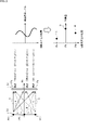
- the pixel detection signal levels DA, DB, and DC at the positions Pa, Pb, and Pc on the image sensor 32 are the following equations (1) to equations, respectively. It is represented by (3).
- the equations (1) to (3) in FIG. 2 have an inverted vertical relationship with the positions Pa, Pb, and Pc on the image sensor 32 in FIG.
- ⁇ 1 is a coefficient with respect to the detection signal level a set according to the incident angle of the light ray from the point light source PA on the subject surface to be restored at the position Pa on the image sensor 32.
- ⁇ 1 is a coefficient with respect to the detection signal level b set according to the incident angle of the light ray from the point light source PB on the subject surface to be restored at the position Pa on the image sensor 32.
- ⁇ 1 is a coefficient with respect to the detection signal level c set according to the incident angle of the light beam from the point light source PC on the subject surface to be restored at the position Pa on the image sensor 32.
- ( ⁇ 1 ⁇ a) in the detection signal level DA indicates the detection signal level due to the light beam from the point light source PA at the position Pa.
- ( ⁇ 1 ⁇ b) in the detection signal level DA indicates the detection signal level due to the light beam from the point light source PB at the position Pa.
- ( ⁇ 1 ⁇ c) in the detection signal level DA indicates the detection signal level due to the light beam from the point light source PC at the position Pa.
- the detection signal level DA is expressed as a composite value of each component of the point light sources PA, PB, and PC at the position Pa multiplied by the respective coefficients ⁇ 1, ⁇ 1, and ⁇ 1.
- the coefficients ⁇ 1, ⁇ 1, and ⁇ 1 are collectively referred to as a coefficient set.
- the coefficient sets ⁇ 2, ⁇ 2, ⁇ 2 correspond to the coefficient sets ⁇ 1, ⁇ 1, ⁇ 1 for the detection signal level DA in the point light source PA, respectively.
- the coefficient sets ⁇ 3, ⁇ 3, ⁇ 3 correspond to the coefficient sets ⁇ 1, ⁇ 1, ⁇ 1 for the detection signal level DA in the point light source Pa, respectively.
- the detection signal level of the pixels at the positions Pa, Pb, and Pc is a value expressed by the sum of the product of the light intensities a, b, and c of the light rays emitted from the point light sources PA, PB, and PC, respectively, and the coefficient. Is. Therefore, these detection signal levels are a mixture of the light intensities a, b, and c of the light rays emitted from the point light sources PA, PB, and PC, respectively, so that the image of the subject is imaged. Is different from.
- the coefficient set ⁇ 1, ⁇ 1, ⁇ 1, the coefficient set ⁇ 2, ⁇ 2, ⁇ 2, and the coefficient set ⁇ 3, ⁇ 3, ⁇ 3 are respectively. Although it will change, by changing this coefficient set, it is possible to reconstruct the restored image (final image) of the subject surface at various distances.
- the in-focus point is deviated in the image pickup by a general image pickup device using a lens.
- the image pickup using the lensless camera realized by the mask 31, the image sensor 32, and the reconstruction unit 33 in FIG. 1 the in-focus point is deviated in the image pickup by a general image pickup device using a lens.
- the image of the subject surface can be reconstructed after imaging.
- the detection signal level shown in the upper right part of FIG. 2 is not the detection signal level corresponding to the image in which the image of the subject is formed, it is not a pixel value but a mere observation value, and is an image consisting of the observation values. Become. Further, the detection signal level shown in the lower right of FIG. 2 consists of a signal value for each pixel corresponding to the image in which the image of the subject is formed, and is a value of each pixel of the restored image (final image), so that it is a pixel value. It becomes.
- the mask 31, the image sensor 32, and the reconstructing unit 33 can function as a so-called lensless camera.
- the image pickup lens is not an indispensable configuration, it is possible to reduce the height of the image pickup apparatus, that is, to reduce the thickness of the light in the configuration that realizes the image pickup function with respect to the incident direction. Further, by changing the coefficient set in various ways, it is possible to reconstruct and restore the final image (restored image) on the subject surface at various distances.
- the image captured by the image sensor 32 before being reconstructed is simply referred to as an captured image, and the image reconstructed and restored by signal processing the captured image is the final image (restored image). It is called. Therefore, from one captured image, an image on a subject surface at various distances can be reconstructed as a final image by variously changing the above-mentioned coefficient set.
- the reconstruction unit 33 includes the above-mentioned coefficient set, and uses the coefficient set according to the distance from the image pickup position to the subject surface, and is the final image (restored image) based on the image captured by the image sensor 32. ) Is reconstructed and output to the recognition processing unit 34.
- the recognition processing unit 34 performs image recognition processing using a DNN (Deep Neural Network) based on the final image supplied from the reconstruction unit 33, and outputs a recognition result.
- DNN Deep Neural Network
- the recognition processing unit 34 includes a DNN first layer processing unit 51-1, a DNN second layer processing unit 51-2, ... A DNN nth layer processing unit 51-n, and a recognition unit 52. ing.
- DNN 1st layer processing unit 51-1, DNN 2nd layer processing unit 51-2, ... DNN nth layer processing unit 51-n executes convolution processing of each layer composed of n layers constituting DNN, respectively. Then, it is output to the subsequent stage, and the DNN nth layer processing unit 51-n, which has executed the processing of the nth layer as the final layer, outputs it to the recognition unit 52 as a convolution result.
- the recognition unit 52 recognizes the object based on the convolution result of the n-layer layer supplied from the DNN n-layer processing unit 51-n, and outputs the recognition result.
- the input image when the distance from the imaging position to the subject is a predetermined distance is defined as the input image X, which is modulated by the mask 31 of the mask pattern A, ignoring the effects of diffraction, noise, and the like, and the image sensor 32.
- the captured image, which is the image observed by the above, shall be represented by A * X. Note that * represents convolution.
- the DNN first layer processing unit 51-1 When the DNN first layer processing unit 51-1 performs the convolution operation of the weight P1 on the final image (restored image) X', the DNN first layer processing unit 51-1 is the processing result of the DNN first layer processing unit 51-1.
- the processing result of the layer is expressed by the following equation (5).
- a convolution operation of the weight P2 is performed on the processing result of the DNN first layer processing unit 51-1, and the DNN third layer processing unit 51-3 performs a convolution operation.
- a convolution operation of the weight P3 is performed on the processing result of the DNN first layer processing unit 51-2, and thereafter, in the DNN nth layer processing unit 51-n, the DNN th (n-1) layer processing unit 51- (n).
- a convolution operation of the weight Pn is performed on the processing result of -1).
- the processing result P1 * P2 * ... Pn * X' is output to the recognition unit 52, and the recognition unit 52 receives the processing result P1 * P2 * ... Pn * X'.
- Processing result P1 * P2 * ... An object recognition process is performed based on Pn * X'.
- the mask pattern of the mask 31 is a MURA (Modified Uniformly Redundant Arrays) pattern, but the mask pattern may be other than this, and may be, for example, a URA (Uniformly Redundant Arrays) pattern.
- MURA Modified Uniformly Redundant Arrays
- URA Uniformly Redundant Arrays
- the recognition process section In 34 the recognition process is performed.
- the final image (restored image) is a captured image A * X modulated by the mask 31 and restored to an image visually recognizable by humans by using the restoration matrix G. ..
- the image input to the recognition processing is an image that can be visually recognized by humans as long as the information necessary for the recognition processing is included.
- the process of restoring the final image (restored image) by the reconstructing unit 33 is not an indispensable process.
- the recognition process by the recognition processing unit 34 is, for example, a face image of a person such as face authentication
- the input image is inevitably a face image of the person, so that the final image (restored image) is reconstructed. Therefore, consideration must be given to privacy protection.
- the face image or the like which is the reconstructed final image (restored image)
- the mask pattern constituting the mask 31 is the above-mentioned mask pattern A convolved with the weight P1 used for the convolution calculation of the DNN first layer processing unit 51-1.
- the image P1 * X'in which the weight P1 is convoluted with respect to the input image X is reconstructed as the final image (restored image).
- the image reconstructed by the reconstructing unit 33 is a human image P1 * X'with the weight P1 convoluted with respect to the final image (restored image) X'corresponding to the input image X.
- the image can include information essential for the recognition process. Even if the mask pattern A is stolen together with the final image and the corresponding restoration matrix G is specified, the reconstructed image contains information essential for recognition processing, but humans can use it. It is not an image that can be visually recognized as a scene, but in other words, it is two-dimensional information that includes only information essential for recognition processing.
- the image processing device 101 of FIG. 3 includes a mask 131, an image sensor 132, a reconstruction unit 133, and a recognition processing unit 134.
- the image sensor 132 and the reconstruction unit 133 have the same configuration as the image sensor 32 and the reconstruction unit 33 of FIG. 1, respectively.
- the basic function of the mask 131 is the same as that of the mask 31 of FIG. 1, but the mask pattern is a convolution operation of the DNN first layer processing unit 51-1 of FIG. 1 with respect to the mask pattern A of FIG. It is a convolution of the weight P1 used in.
- the mask pattern of the mask 131 will be referred to as a mask pattern A * P1.
- the recognition processing unit 134 has the same basic functions as the recognition processing unit 34 in FIG. 1, but corresponds to the DNN first layer processing unit 51-1 in FIG. 1 that realizes the processing of the first layer of the DNN. No configuration is provided.
- the recognition processing unit 134 includes a DNN second layer processing unit 151-2 to a DNN nth layer processing unit 151-n, and a recognition unit 152.
- the DNN 2nd layer processing unit 151-2 to the DNN nth layer processing unit 151-n and the recognition unit 152 the DNN 2nd layer processing unit 51-2 to the DNN nth layer processing unit in FIG. 1 This is the same as the 51-n and the recognition unit 52.
- the captured image captured by the image sensor 132 by applying the modulation by the mask 131 to the input image X is expressed as A * P1 * X.
- the reconstruction unit 133 multiplies the captured image A * P1 * X by the restoration matrix G, so that the image as represented by the following equation (6) is used as the reconstruction image in the recognition processing unit 134. Output.
- the final image (restored image) reconstructed in the reconstructed unit 133 represented by the equation (6) is the final image corresponding to the input image X, which is the processing result in the DNN first layer processing unit 51-1.
- the image P1 * X'in which the weight P1 is convoluted with respect to X' is reconstructed as the final image (restored image).
- the convolution calculation of the weight P1 by the DNN first layer processing unit 51-1 in the recognition processing unit 34 of FIG. 1 becomes an optical process by the mask pattern of the mask 131. Will be replaced.
- the image reconstructed by the reconstructing unit 133 is required for the recognition process because the weight P1 is convoluted with respect to the final image X'corresponding to the input image X.
- the information will be recorded as an captured image by the image sensor 132.
- the processing of the first layer among the processing of the DNN multilayer layer is processed in parallel by a plurality of channels, and a plurality of features required for each channel are obtained. Subsequent object recognition is generally performed based on the vector.
- the process of the first layer of DNN is performed by a plurality of channels as shown in FIG.
- the convolution result of 64 channels is output as the processing of the first layer (224 ⁇ 224 ⁇ 64) (. convolutional ReLU (Rectified LinearUnit).
- the layer is reduced to 112 x 112 resolution, and after that, 128 channels are convolved for 112 x 112 resolution (112 x 112 x 128).
- the layer is reduced to 56 ⁇ 56 resolution by Maxpooling using this result, and after that, 256 channel convolution is performed for 56 ⁇ 56 resolution (56 ⁇ 56 ⁇ 256).
- the layer is reduced to 28 ⁇ 28 resolution by Maxpooling using this result, and after that, 512 channels are convolved for 28 ⁇ 28 resolution (28 ⁇ 28 ⁇ 512).
- the layer is reduced to 14 ⁇ 14 resolution, and after that, 512 channels are convolved for 14 ⁇ 14 resolution (14 ⁇ 14 ⁇ 512).
- the layer is reduced to 7x7 resolution by Maxpooling using this result, and after that, 512 channels are convolved for 7x7 resolution (7x7x512).
- the feature vector determination result (fully connected + ReLU) (1 x 1 x 4096) is generated based on the 512-channel convolution result (7 x 7 x 512) at this 7 x 7 resolution.
- the probability function (softmax) based on the judgment result (fully connected + ReLU) (1 ⁇ 1 ⁇ 4096) of the feature vector is output as the recognition result.
- the image recognition device of the present disclosure is also required to have a configuration in which a plurality of channels are formed according to the number of channels in the first layer.
- the image processing apparatus corresponding to the plurality of channels of the present disclosure has a configuration in which the image processing apparatus 101 described with reference to FIG. 3 is made into a plurality of channels, for example, as shown by the image processing apparatus 111 of FIG. Will be done.
- the image processing device 111 of FIG. 5 includes a mask 131', an image sensor 132, a dividing unit 161, a Ch1 reconstructing unit 162-1 to a Chm reconstructing unit 162-m, and a recognition processing unit 134'.
- a mask 131' an image sensor 132
- a dividing unit 161 a Ch1 reconstructing unit 162-1 to a Chm reconstructing unit 162-m
- a recognition processing unit 134' the description will proceed on the assumption that the number of channels in the first layer is m.
- the basic function of the mask 131' is the same as that of the mask 131, but the mask pattern B is divided into sub-areas by the number of channels.
- each sub-area which is the basic pattern, is a mask pattern used in so-called lensless cameras such as the MURA pattern and the M-sequence, and is a binary pattern.
- the mask pattern of the sub-area SA1 is composed of As * Ps11 and the mask pattern of the sub-area SA2 is composed of As * Ps21.
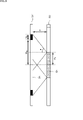
- FIG. 7 is a side sectional view of the mask 131'and the image sensor 132 as viewed from a direction perpendicular to the incident direction of the incident light.
- the lower direction in the figure is the incident direction of the incident light
- the range of the width 2 ⁇ wb between the sub-areas SA1 and SA2 on the mask 131' is the margin region BL.
- the captured image can be captured in the sub-area SA1 of the mask 131'.
- the effective region on the image sensor 132 is referred to as the effective region EA1
- the effective region on the image sensor 132 in which the captured image can be captured with respect to the sub-area SA2 is referred to as the effective region EA2.
- the region Dz1 between the effective regions EA1 and EA2 becomes a dead zone in which imaging is impossible.
- the width wb of the margin area BL has a mask pattern of the adjacent sub-area in that range. It will be the size required to prevent it from entering.
- the mask size (distance from the center of the rectangular subarea in the mask 131'to the edge of the subarea) wm and the sensor size (the effective area of the rectangular subarea of the image sensor 132) Distance from the center to the edge of the effective region)
- the relationship with ws is wm> ws.
- a margin region BL' including a width wc may be set between the widths wb.
- a dead zone that cannot be imaged is set, which consists of a region Dz1'wider than the region Dz1 in the upper part of FIG.
- a light-shielding wall in the direction perpendicular to the incident direction of the incident light may be formed at the end of each sub-area to suppress interference between adjacent sub-areas. By doing so, it is possible to reduce the margin area and widen the effective area of the image sensor 132.
- the mask pattern As which is the basic pattern used to generate the mask pattern for each sub-area, the influence of interference between adjacent sub-areas can be reduced, and channel separation by signal processing can be easily performed. You may do it.
- a mask pattern As that is a basic pattern for each channel that is, for each subarea, using pseudo-random signals obtained from M-sequence or Gold code that are not correlated with each other, the subarea next to the observed value is tentatively used. Even if the signals from are mixed, the influence of interference between adjacent sub-areas can be minimized by reducing the correlation with the basic pattern for each channel. Ideally, there is no correlation between adjacent sub-areas for the basic pattern for each channel, but the correlation is minimized by a pseudo-random signal.
- a sub-area may be set on the mask 131'so that the dead zone generated on the image sensor 132 described with reference to FIG. 7 does not occur. In this case, the sub-areas are completely separated. May be in contact with.
- the mask patterns As which are the basic patterns for each sub-area
- the mask patterns of the adjacent sub-areas overlap as shown in FIG. 9 unless the effective areas on the image sensor 132 overlap. It is also possible to arrange them in such a way.
- the images are taken in the effective regions EA1 and EA2 on the image sensor 132. In the image, they do not interfere with each other.
- the image sensor 132 captures an image captured image B * X with respect to the input image X based on the incident light modulated by the mask 131'composed of the mask pattern B, and outputs the captured image B * X to the dividing unit 161.
- the division unit 161 divides the captured image B * X for each of the sub-areas SA1 to SAm, and outputs the captured image B * X to the Ch1 reconstruction unit 162-1 to Chm reconstruction unit 162-m of the corresponding channel.
- the division unit 161 outputs the captured image As * Ps11 * X of the sub-area SA1 corresponding to the channel 1 of the captured images B * X to the Ch1 reconstruction unit 162-1, and among the captured images B * X.
- the captured image As * Ps21 * X of the sub-area SA2 corresponding to the channel 2 is output to the Ch2 reconstruction unit 162-2, and ...
- the sub-area SAm corresponding to the channel m is imaged.
- the image As * Psm1 * X is output to the Chm reconstruction unit 162-m.
- the Ch1 reconstruction unit 162-1 to Chm reconstruction unit 162-m are low corresponding to the sub-area with respect to the captured images As * Ps11 * X to As * Psm1 * X of the sub-areas SA1 to SAm of the respective channels.
- the restoration matrix Gs corresponding to the mask pattern As of the resolution image the image is reconstructed and output to the recognition processing unit 134'for each channel.
- the Ch1 reconstruction unit 162-1 of the channel 1 multiplies the captured image As * Ps11 * X of the subarea SA1 by the restoration matrix Gs corresponding to the mask pattern As, so that the DNN first layer in FIG. 1
- the image Ps11 * X'processed by the processing unit 52-1 is restored, and the Ch1 second layer processing unit 151-1-2 and the Ch2 second layer processing unit 151-2-2 of the recognition processing unit 134'are restored. ⁇ ⁇ , Output to Chm 2 2nd layer processing unit 151-m 2-2.
- the Ch2 reconstruction unit 162-2 of the channel 2 multiplies the captured image As * Ps21 * X of the subarea SA2 by the restoration matrix Gs corresponding to the mask pattern As, so that the DNN first in FIG.
- the image Ps21 * X'processed by the layer processing unit 52-1 is restored, and the Ch1 second layer processing unit 151-1-2 and the Ch2 second layer processing unit 151-2-2 of the recognition processing unit 134'are restored. , ..., Output to Chm 2 2nd layer processing unit 151-m 2-2.
- the Chm reconstruction unit 162-m of the channel m multiplies the captured image As * Psm1 * X of the sub-area SAm by the restoration matrix Gs corresponding to the mask pattern As, so that the DNN first layer of FIG. 1 is obtained.
- the image Psm1 * X'processed by the processing unit 52-1 is restored, and the Ch1 second layer processing unit 151-1-2 and the Ch2 second layer processing unit 151-2-2 of the recognition processing unit 134'are restored. ⁇ ⁇ , Output to Chm 2 2nd layer processing unit 151-m 2-2.
- the recognition processing unit 134' is Ch1 second layer processing unit 151-1-2 to Chm 2 second layer processing unit 151-m 2-2 , Ch1 third layer processing unit 151-1-3 to Chm 3 third layer.
- the processing unit 151-m 3 -3, ... Ch1 nth layer processing unit 151-1-n to Chm nth layer processing unit 151-mn- n are provided.
- the recognition processing unit 134' has a configuration corresponding to the DNN second layer processing unit 151-2 to the DNN layer n layer processing unit 151-n in the recognition processing unit 134 of FIG. 3 of a plurality of channels.
- Ch1 second layer processing unit 151-1-2 to Chm 2 second layer processing unit 151-m 2-2 , Ch1 third layer processing unit 151-1-3 to Chm 3 third layer processing unit. 151-m 3 -3, ... Ch1 nth layer processing unit 151-1-n to Chm nth layer processing unit 151-mn- n are the reconstructed images Ps11 * X'of channel 1. For the reconstructed image Ps21 * X', ... Of the channel 2, and the reconstructed image Psm1 * X'of the channel m, the weights are sequentially convoluted to calculate the feature vector, and the recognition unit 152. Output to'.
- the recognition unit 152' is a convolution operation result supplied from the Ch1 nth layer processing unit 151-1- n to the Chmn nth layer processing unit 151-mn-n, which is the final stage of the recognition processing unit 134'.
- the object in the subject of the input image X is recognized based on the feature vector.
- the Ch1 reconstruction unit 162-1 to Chm reconstruction unit 162-m use the mask pattern As for the captured images As * Ps11 * X to As * Psm1 * X of the subareas SA1 to SAm of the respective channels.
- the processing result by the DNN first layer processing unit 52-1 in FIG. 1 that is, the image Ps11 * X'to Psm1 * which is the processing result of the DNN first layer.
- X' is output to the recognition processing unit 134'.
- the reconstructed images Ps11 * X'to Psm1 * X' are the first layer of DNN in each channel with respect to the low-resolution restored image in which the image sensor 132 is divided into sub-areas for each channel. It is output as the processing result of the processing.
- the restored image reconstructed in each channel contains information necessary for recognition processing, but recognition processing is performed in a state where it is difficult for humans to visually recognize the scene or object. Since it is output to the unit 134', privacy protection is performed. In addition, since privacy protection is applied to the restored image, special management in consideration of privacy is not required for the restored image.
- the processing of the DNN first layer in each channel is transferred to the optical processing in the mask 131', the configuration corresponding to the DNN first layer processing unit 52-1 in FIG. 1 for each channel. Is not required, so that the device configuration can be simplified.
- the configuration corresponding to the DNN first layer processing unit 52-1 becomes unnecessary, the processing load in the image processing device 111 can be reduced.
- step S11 the image sensor 132 is a subject modulated by the mask 131'of the mask pattern B in which the weight related to the processing of the DNN first layer for each channel is convoluted in the mask pattern As which is the basic pattern for each sub-area.
- the captured image B * X is generated and output to the division unit 161.
- step S12 the division unit 161 divides the captured image B * X into the restored images As * Ps11 * X to As * Psm1 * X for each sub-area corresponding to each channel, and the Ch1 reconstruction unit of the corresponding channel. Output to 162-1 to Chm reconstruction unit 162-m.
- step S13 the Ch1 reconstruction unit 162-1 to the Chm reconstruction unit 162-m multiply the images As * Ps11 * X to As * Psm1 * X by the restoration matrix Gs for each channel, and the DNN first layer.
- the restored image consisting of the processing result of the eyes is obtained and output to the Ch1 second layer processing unit 151-1-2 to the Chm 2 second layer processing unit 151-m 2-2 of the recognition processing unit 134'.
- step S14 in the recognition processing unit 134', the Ch1 second layer processing unit 151-1-2 to Chm 2 second layer processing unit 151-m 2-2 , Ch1 third layer processing unit 151-1-3 to Chm. 3 Third layer processing unit 151-m 3 -3, ... Ch1 nth layer processing unit 151-1-n to Chm nth layer processing unit 151-mn- n are DNN th units for each channel. The processing of the second and subsequent layers is executed, the feature vector is obtained, and it is output to the recognition unit 152'.
- step S15 the recognition unit 152'executes the object recognition process based on whether or not the information of the feature vector of each channel matches the feature vector of the object, and outputs the recognition result.
- the restored image reconstructed in each channel by the configuration functioning as a lensless camera is output to the recognition processing unit 134'in a state where it is difficult for human eyes to recognize it as an object. Will be done.
- the recognition processing unit 134'in a state where it is difficult for human eyes to recognize it as an object. Will be done.
- the processing of the first layer of DNN in FIG. 1 in each channel is transferred to the optical processing in the mask 131', the processing of the first layer of DNN in FIG. 1 for each channel is realized. Since the configuration for this is not required, it is possible to simplify the device configuration.
- the image captured by the image sensor 132 is divided by using the mask pattern in which the mask 131'is provided with a sub-area for each channel and the weights related to the processing of the first layer of the DNN are convoluted.
- An example has been described in which the unit 161 is divided into channels and output to the Ch1 reconstruction unit 162-1 to the Chm reconstruction unit 162-m of each channel.
- the Ch1 reconstruction unit 162-1 to the Chm reconstruction unit 162-m of each channel are made to extract and process the information of the sub-area necessary for the processing of its own channel from the captured image B * X. Therefore, the configuration may be such that the divided portion 161 is omitted.
- the mask pattern is generated from the weights used for the processing of the first layer of DNN, and the target of optimization by two different types of indicators is common only to the weights of the first layer of DNN.
- the first index is the loss function, which is the degree of deviation from the correct answer data of the ID classification and recognition result that directly defines the performance of the recognition processing.
- the network of the first layer and the second and subsequent layers of the recognition process is optimized so that this loss function becomes small.
- the second index ensures that the index for ensuring privacy protection, that is, the reconstructed final image (restored image) is an image that is difficult for humans to visually recognize as a scene or an object.
- the mask pattern itself a network that performs image restoration processing to restore the modulated image generated when the original image is modulated by the mask pattern to the original image is separately provided. Let them learn. This image restoration processing network trains so that the difference between the original image and the modulated image becomes small.
- the difference from the original image is evaluated by an index expressing the image similarity such as PSNR, MSE, SSIM, VGG16, and the evaluation value is lowered.
- modulation processing is performed so that only the information required for the recognition process is left from the original face image and the information required for the restoration of the face image is minimized.
- the weight of the first layer of DNN is obtained by learning so as to form a mask pattern such that the above is applied.
- the captured image captured by modulating the input image by the mask pattern contains only the information required for the subsequent recognition process. Will be included.
- the final image (restored image) is so different that it is difficult for humans to visually recognize it as an input image, that is, an image with high precision protection. It becomes possible to do.
- the recognition rate when a normal image recognizer is operated may be used for the restored image output by the image restoration processing network.
- the recognition rate by learning the weight of the first layer of DNN so that the recognition rate becomes low, it is possible to make a system capable of recognition processing while ensuring privacy protection.
- Second embodiment >>
- the mask 131 is divided into sub-areas, channels are assigned to each sub-area, a mask pattern in which the weights related to the processing of the corresponding DNN first layer are convoluted is generated, and images are taken by the image sensor 132.
- An example has been described in which the captured image is divided into sub-area units and the processing result of the first layer of the DNN for each channel is obtained as a reconstructed image.
- the mask pattern which is the basic pattern in the mask 131, has low correlation with each other for each channel
- the patterns in which the weights convoluted in the processing of the first layer of DNN are convoluted are superimposed on all the basic patterns. You may use it.
- the mask pattern Ki which is the basic pattern set for each channel, as in the following equation (8), the correlation between the basic patterns of each channel is the lowest.
- I is an identity matrix. That is, the mask pattern Ki is uncorrelated and becomes an identity matrix when multiplied by itself.
- the mask pattern C is set so as to be expressed by the following equation (9).
- Pi1 is a weight used in the convolution operation of the DNN first layer of channel i.
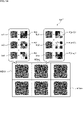
- the mask pattern C represented by the equation (9) can be schematically represented as shown in FIG.
- each basic pattern of the m channel is set to Ki having a low correlation with each other, and the mask pattern Ki * Pi1 of each channel in which the weight Pi1 convoluted in the processing of the DNN first layer of each channel is convoluted.
- the mask pattern C is formed by superimposing the m channels.
- "+" shown in FIG. 11 represents the superposition of mask patterns.
- the input image X is modulated by using the mask pattern C configured in this way, and the captured image C * X captured with the basic pattern of each channel as expressed by the following equation (10).
- the mask pattern Ki as a restoration matrix, it is possible to obtain the processing result of the first layer of DNN for each channel (extracted from the captured image C * X).
- the recognition process uses the feature vector obtained in sub-area units.
- each basic pattern and DNN are used for each channel.
- the feature vector is obtained using the high-resolution restored image using the entire image captured by the image sensor 132. Is possible.
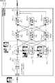
- FIG. 12 shows a configuration example of an image processing device 111 that realizes image recognition processing by using a mask having a mask pattern C described with reference to FIG.
- the same reference numerals are given to the configurations having the same functions as the image processing device 111 of FIG. 5, and the description thereof will be omitted as appropriate.
- the difference from the image processing device 111 of FIG. 5 is that the mask 131', the division unit 161 and the Ch1 reconstruction unit 162-1 to Chm reconstruction unit 162-m are replaced.
- the point is that the mask 131'' and the Ch1 reconstruction unit 171-1 to Chm reconstruction unit 171-m are provided.
- the mask 131 ′′ is composed of a basic pattern having a low correlation for each of the above-mentioned channels and a mask pattern C in which the weight Pi1 convoluted in the processing of the DNN first layer of each channel is convoluted.
- the Ch1 reconstruction unit 171-1 to Chm reconstruction unit 171-m use the mask pattern Ki, which is the basic pattern in the mask 131'', as the restoration matrix in each channel, so that each channel is obtained from the captured image C * X.
- the processing result obtained by multiplying the reconstructed image X'in the above by the weight Pi1 of the first layer of the DNN is obtained (the processing result is extracted) and output to the recognition processing unit 134'in the subsequent stage.
- the configuration of the recognition processing unit 134'in FIG. 12 is the same as the configuration of the recognition processing unit 134' in FIG. 5, but in each configuration of the recognition processing unit 134' in FIG. 5, the processing target is the channel.
- the information is assigned to each sub-area, whereas each configuration of the recognition processing unit 134'in FIG. 12 is different in that it is information of the entire area captured by the image sensor 132 in each channel.
- step S31 the image sensor 132 uses the mask 131'of the mask pattern C in which the mask pattern Ki, which is the basic pattern for each channel, and the mask pattern, in which the weight Pi1 related to the processing of the first layer of the DNN is convoluted, are superimposed.
- the captured image C * X is generated and output to the Ch1 reconstruction unit 171-1 to the Chm reconstruction unit 171-m.
- step S32 the Ch1 reconstruction unit 171-1 to the Chm reconstruction unit 171-m multiply the captured image C * X by the mask pattern Ki, which is the basic pattern of each channel, in each channel.
- Ki the mask pattern of each channel
- step S34 the recognition unit 152'executes the object recognition process based on whether or not the information of the feature vector of each channel matches the feature vector of the object, and outputs the recognition result.
- the restored image reconstructed in each channel is output to the recognition processing unit 134'in a state where it is difficult for humans to visually recognize the object, so privacy protection is provided. It becomes possible to realize the above, and special management considering privacy is not required for the restored image.
- the processing by the DNN first layer processing unit 52-1 in FIG. 1 in each channel is transferred to the optical processing in the mask 131'', the processing in the DNN first layer for each channel can be performed. Since it is not required, it is possible to simplify the device configuration.
- the processing load in the image processing apparatus 111 can be reduced.
- the feature vector of each channel can be obtained by using the entire image captured by the image sensor 132, it is possible to obtain the feature vector of each channel with higher accuracy than to obtain the feature vector in sub-area units. It becomes.
- First application example As a method of performing different convolutions of a plurality of channels in parallel, division into sub-areas and superposition of basic patterns having low correlation with each other may be combined.
- the entire mask 131 ′ ′′ is divided into a plurality of subareas MSA1 to MSAx, and each of the subareas MSA1 to MSAx correlates with each other.
- the sub-area MSA1 to MSAx are divided, and in the sub-area MSA1, the weight P11 used in the processing of the first layer of the DNN is convoluted into the basic pattern Ka1 in the channel 1 (Ch1).
- a mask pattern is formed in which the weight Pt1 used in the processing of the first layer of the DNN is superimposed on the mask pattern in which the weight Pt1 is folded.
- the basic patterns Ka1 to Kat have low correlation with each other.
- a mask pattern is formed in which the basic pattern Kbu in t + u)) is superimposed on the mask pattern in which the weight P (t + u) 1 used in the processing of the first layer of the DNN is folded.
- the basic patterns Kb1 to Kbu have low correlation with each other.
- the resolution and the number of channels for each channel have a trade-off relationship in the division of the sub-area, and the number of channels and the signal processing are extracted in the superposition of the basic patterns having low correlation with each other. It is possible to balance the fact that the signal-to-noise ratio of the signal is in a trade-off relationship.
- the configuration of the image processing device 111 when such a mask pattern is used has a low correlation for each channel with the configuration corresponding to the division portion 161 required when using the mask using the subarea described above.
- the processing result of the DNN 1st layer of each channel is extracted from the captured image using the mask in which the mask pattern in which the basic pattern and the weight used for the processing of the DNN 1st layer are overlapped is superimposed. It is a combination with the configuration corresponding to the reconstruction part of. Since the individual configurations used for the combination are the same as the configurations described above, the description thereof will be omitted.
- Second application example When dividing the entire mask into sub-areas, the size and shape of each sub-area do not necessarily have to be the same.
- the sub-area BSA is arranged in the upper left part of the figure, and the sub-area BSA is similar to the sub-area BSA on the right side.
- Four subareas SSA1 to SSA4 having a size of 1/4, that is, a resolution of 1/4 are arranged, and a horizontally long subarea LSA having a different shape is provided at the lower part of the figure. It may be arranged.
- a vertically long sub-area may be arranged as in the horizontally long sub-area LSA.
- the resolution can be assigned according to the importance of the channel, etc., and the S / N ratio can be preferentially increased or decreased. Can be done.
- Example of execution by software By the way, the series of processes described above can be executed by hardware, but can also be executed by software.
- the programs that make up the software may execute various functions by installing a computer embedded in dedicated hardware or various programs. It is installed from a recording medium on a possible, eg, general purpose computer.
- FIG. 16 shows a configuration example of a general-purpose computer.
- This personal computer has a built-in CPU (Central Processing Unit) 1001.
- the input / output interface 1005 is connected to the CPU 1001 via the bus 1004.
- a ROM (Read Only Memory) 1002 and a RAM (Random Access Memory) 1003 are connected to the bus 1004.
- the input / output interface 1005 includes an input unit 1006 composed of input devices such as a keyboard and a mouse for inputting operation commands by the user, an output unit 1007 for outputting a processing operation screen and an image of processing results to a display device, and programs and various data. It is composed of a storage unit 1008 including a hard disk drive for storing, a LAN (Local Area Network) adapter, and the like, and is connected to a communication unit 1009 which executes communication processing via a network represented by the Internet.
- magnetic discs including flexible discs
- optical discs including CD-ROM (Compact Disc-Read Only Memory), DVD (Digital Versatile Disc)
- optical magnetic discs including MD (Mini Disc)
- a drive 1010 for reading / writing data is connected to a removable storage medium 1011 such as a memory.
- the CPU 1001 is read from a program stored in the ROM 1002 or a removable storage medium 1011 such as a magnetic disk, an optical disk, a magneto-optical disk, or a semiconductor memory, installed in the storage unit 1008, and loaded from the storage unit 1008 into the RAM 1003. Various processes are executed according to the program.
- the RAM 1003 also appropriately stores data and the like necessary for the CPU 1001 to execute various processes.
- the CPU 1001 loads the program stored in the storage unit 1008 into the RAM 1003 via the input / output interface 1005 and the bus 1004 and executes the above-mentioned series. Is processed.
- the program executed by the computer can be recorded and provided on the removable storage medium 1011 as a package medium or the like, for example. Programs can also be provided via wired or wireless transmission media such as local area networks, the Internet, and digital satellite broadcasts.
- the program can be installed in the storage unit 1008 via the input / output interface 1005 by mounting the removable storage medium 1011 in the drive 1010. Further, the program can be received by the communication unit 1009 via a wired or wireless transmission medium and installed in the storage unit 1008. In addition, the program can be installed in the ROM 1002 or the storage unit 1008 in advance.
- the program executed by the computer may be a program in which processing is performed in chronological order according to the order described in the present specification, in parallel, or at a necessary timing such as when a call is made. It may be a program in which processing is performed.
- the CPU 1001 in FIG. 16 includes a division unit 161 in FIG. 5, a Ch1 reconstruction unit 162-1 to a Chm reconstruction unit 162-m, a recognition processing unit 134', and a Ch1 reconstruction unit 171-1 in FIG.
- the functions of the Chm reconstruction unit 171-m and the recognition processing unit 134' are realized.
- the system means a set of a plurality of components (devices, modules (parts), etc.), and it does not matter whether all the components are in the same housing. Therefore, a plurality of devices housed in separate housings and connected via a network, and a device in which a plurality of modules are housed in one housing are both systems. ..
- the present disclosure can have a cloud computing configuration in which one function is shared by a plurality of devices via a network and jointly processed.
- each step described in the above flowchart can be executed by one device or shared by a plurality of devices.
- the plurality of processes included in the one step can be executed by one device or shared by a plurality of devices.
- a mask that modulates and transmits incident light An image sensor that captures a modulated image based on the incident light modulated by the mask, and an image sensor.
- An image processing apparatus including a signal processing unit that applies signal processing based on the mask pattern of the mask to the modulated image.
- the signal processing unit performs signal processing based on the mask pattern on the modulated image on a plurality of channels.
- the mask pattern is set for each of the channels and is set.
- the pattern set for each channel is a pattern in which the weight used for signal processing for each channel is weighted and added to the binary pattern which is the basic pattern set for each channel.
- Processing device ⁇ 3> The incident light is reflected light reflected from the subject.
- the signal processing is an image recognition processing of the subject using a DNN (Deep Neural Network).
- the image processing apparatus according to ⁇ 2>, wherein the weight is the weight of the first layer of the DNN.
- the weight of the first layer of the DNN is the same as the original image captured by the image sensor so that the recognition accuracy by the image recognition process is higher and the mask is not modulated.
- the image processing apparatus according to ⁇ 3>, which is learned so as to have a lower degree of similarity to a restored image that restores the modulated image by using the weight of the first layer of the DNN.
- the mask is divided into sub-areas by the number of the channels.
- the image processing apparatus according to ⁇ 2>, wherein a pattern for each channel is arranged in each of the sub-areas to form the mask pattern.
- a margin area including a light-shielding area is provided between the sub-areas.
- the width of the margin region is set based on the FOV (Field of View) of the pixels of the image sensor.
- a light-shielding wall is provided between the plurality of sub-areas.
- the plurality of sub-areas have the same size and shape.
- the image processing apparatus according to ⁇ 5>, wherein the sizes and shapes of the plurality of sub-areas are not the same.
- the basic pattern set for each of the channels constituting the patterns arranged in each of the sub-areas is set to be uncorrelated to each other or lower than a predetermined correlation.
- the basic pattern set for each of the channels constituting the patterns arranged in each of the sub-areas is set to be uncorrelated with each other using a pseudo-random signal or set lower than a predetermined correlation.
- the image processing apparatus according to ⁇ 5>.
- ⁇ 14> The image processing apparatus according to ⁇ 13>, wherein the basic pattern set for each of the channels is set to be uncorrelated to each other or lower than a predetermined correlation.
- ⁇ 15> The image processing apparatus according to ⁇ 14>, wherein the basic pattern set for each of the channels is set to be uncorrelated with each other using a pseudo-random signal or lower than a predetermined correlation.
- ⁇ 16> The mask is divided into sub-areas by the number of the channels. Patterns of the plurality of channels are arranged in each of the sub-areas.
- the image processing apparatus according to ⁇ 2>, wherein the pattern for each sub-area is a superposition of patterns corresponding to a plurality of channels.
- ⁇ 17> The image processing apparatus according to any one of ⁇ 1> to ⁇ 16>, wherein the mask pattern is composed of transmission, shading, and an arbitrary intermediate value.
- the mask pattern is composed of a diffraction grating.
- a mask that modulates and transmits incident light An image sensor that captures a modulated image based on the incident light modulated by the mask, and an image sensor.
- An image processing method for an image processing apparatus including a signal processing unit that adds signal processing based on the mask pattern of the mask to the modulated image.
- the signal processing unit is an image processing method for applying signal processing based on the mask pattern of the mask to the modulated image.
- a mask that modulates and transmits incident light A computer that controls an image processing apparatus including an image sensor that captures an image as a modulated image based on the incident light modulated by the mask.
Landscapes
- Engineering & Computer Science (AREA)
- Theoretical Computer Science (AREA)
- Multimedia (AREA)
- Physics & Mathematics (AREA)
- General Physics & Mathematics (AREA)
- Computer Vision & Pattern Recognition (AREA)
- Computing Systems (AREA)
- Evolutionary Computation (AREA)
- Health & Medical Sciences (AREA)
- General Health & Medical Sciences (AREA)
- Artificial Intelligence (AREA)
- Databases & Information Systems (AREA)
- Medical Informatics (AREA)
- Software Systems (AREA)
- Signal Processing (AREA)
- Vascular Medicine (AREA)
- Image Processing (AREA)
Priority Applications (2)
| Application Number | Priority Date | Filing Date | Title |
|---|---|---|---|
| JP2022568162A JP7782461B2 (ja) | 2020-12-08 | 2021-11-24 | 画像処理装置、および画像処理方法、並びにプログラム |
| US18/255,117 US12499553B2 (en) | 2020-12-08 | 2021-11-24 | Image processing apparatus and image processing method |
Applications Claiming Priority (2)
| Application Number | Priority Date | Filing Date | Title |
|---|---|---|---|
| JP2020203416 | 2020-12-08 | ||
| JP2020-203416 | 2020-12-08 |
Publications (1)
| Publication Number | Publication Date |
|---|---|
| WO2022124067A1 true WO2022124067A1 (ja) | 2022-06-16 |
Family
ID=81974428
Family Applications (1)
| Application Number | Title | Priority Date | Filing Date |
|---|---|---|---|
| PCT/JP2021/042882 Ceased WO2022124067A1 (ja) | 2020-12-08 | 2021-11-24 | 画像処理装置、および画像処理方法、並びにプログラム |
Country Status (3)
| Country | Link |
|---|---|
| US (1) | US12499553B2 (https=) |
| JP (1) | JP7782461B2 (https=) |
| WO (1) | WO2022124067A1 (https=) |
Cited By (1)
| Publication number | Priority date | Publication date | Assignee | Title |
|---|---|---|---|---|
| JP2024030614A (ja) * | 2022-08-24 | 2024-03-07 | トヨタ自動車株式会社 | 情報処理方法 |
Families Citing this family (1)
| Publication number | Priority date | Publication date | Assignee | Title |
|---|---|---|---|---|
| JP7317246B1 (ja) * | 2022-08-02 | 2023-07-28 | 三菱電機株式会社 | 推論装置、推論方法及び推論プログラム |
Citations (2)
| Publication number | Priority date | Publication date | Assignee | Title |
|---|---|---|---|---|
| WO2017145348A1 (ja) * | 2016-02-26 | 2017-08-31 | 株式会社日立製作所 | 撮像装置 |
| JP2019003609A (ja) * | 2017-06-09 | 2019-01-10 | キヤノン株式会社 | 画像処理方法、画像処理装置、撮像装置および画像処理プログラム |
Family Cites Families (2)
| Publication number | Priority date | Publication date | Assignee | Title |
|---|---|---|---|---|
| EP3731521B1 (en) | 2017-12-22 | 2022-04-27 | Sony Group Corporation | Imaging device, imaging method, and imaging element |
| US20250173877A1 (en) * | 2023-11-28 | 2025-05-29 | Pixelworks Semiconductor Technology (Shanghai) Co. Ltd. | Methods and systems motion vector calculation and processing |
-
2021
- 2021-11-24 JP JP2022568162A patent/JP7782461B2/ja active Active
- 2021-11-24 US US18/255,117 patent/US12499553B2/en active Active
- 2021-11-24 WO PCT/JP2021/042882 patent/WO2022124067A1/ja not_active Ceased
Patent Citations (2)
| Publication number | Priority date | Publication date | Assignee | Title |
|---|---|---|---|---|
| WO2017145348A1 (ja) * | 2016-02-26 | 2017-08-31 | 株式会社日立製作所 | 撮像装置 |
| JP2019003609A (ja) * | 2017-06-09 | 2019-01-10 | キヤノン株式会社 | 画像処理方法、画像処理装置、撮像装置および画像処理プログラム |
Cited By (3)
| Publication number | Priority date | Publication date | Assignee | Title |
|---|---|---|---|---|
| JP2024030614A (ja) * | 2022-08-24 | 2024-03-07 | トヨタ自動車株式会社 | 情報処理方法 |
| JP7708035B2 (ja) | 2022-08-24 | 2025-07-15 | トヨタ自動車株式会社 | 情報処理方法 |
| US12462542B2 (en) | 2022-08-24 | 2025-11-04 | Toyota Jidosha Kabushiki Kaisha | Information processing method |
Also Published As
| Publication number | Publication date |
|---|---|
| JP7782461B2 (ja) | 2025-12-09 |
| JPWO2022124067A1 (https=) | 2022-06-16 |
| US12499553B2 (en) | 2025-12-16 |
| US20240114254A1 (en) | 2024-04-04 |
Similar Documents
| Publication | Publication Date | Title |
|---|---|---|
| Liang | Punching holes in light: recent progress in single-shot coded-aperture optical imaging | |
| KR102543392B1 (ko) | 깊이 획득을 위한 명시야 이미지 처리 방법 | |
| US9338380B2 (en) | Image processing methods for image sensors with phase detection pixels | |
| JP7363765B2 (ja) | 画像処理装置、および撮像装置、並びに画像処理方法 | |
| EP3700197B1 (en) | Imaging device and method, and image processing device and method | |
| JPWO2017145348A1 (ja) | 撮像装置 | |
| JP7156297B2 (ja) | 撮像素子、画像処理装置、画像処理方法、および、プログラム | |
| JP7782461B2 (ja) | 画像処理装置、および画像処理方法、並びにプログラム | |
| JP7552746B2 (ja) | 撮像装置及び信号処理装置 | |
| US20200275038A1 (en) | Imaging apparatus and method, and image processing apparatus and method | |
| EP3780594A1 (en) | Imaging device and method, image processing device and method, and imaging element | |
| KR20200135305A (ko) | 촬상 소자, 촬상 장치, 및 정보 처리 방법 | |
| Stork et al. | Imaging Without Lenses: New imaging systems, microscopes, and sensors rely on computation, rather than traditional lenses, to produce a digital image | |
| WO2023222278A1 (en) | Multispectral optical sensor, camera system and parallax compensation method | |
| WO2025041799A1 (ja) | 情報処理装置、撮像システムおよび情報処理方法 | |
| WO2025041801A1 (ja) | 情報処理システム、情報処理装置および情報処理方法 | |
| CN119136065A (zh) | 一种基于光谱偏振的大动态成像装置、方法及存储介质 | |
| Sure et al. | Optical imaging with extended field of view using various multiplexing methods of coded phase apertures |
Legal Events
| Date | Code | Title | Description |
|---|---|---|---|
| 121 | Ep: the epo has been informed by wipo that ep was designated in this application |
Ref document number: 21903171 Country of ref document: EP Kind code of ref document: A1 |
|
| ENP | Entry into the national phase |
Ref document number: 2022568162 Country of ref document: JP Kind code of ref document: A |
|
| WWE | Wipo information: entry into national phase |
Ref document number: 18255117 Country of ref document: US |
|
| NENP | Non-entry into the national phase |
Ref country code: DE |
|
| 122 | Ep: pct application non-entry in european phase |
Ref document number: 21903171 Country of ref document: EP Kind code of ref document: A1 |
|
| WWG | Wipo information: grant in national office |
Ref document number: 18255117 Country of ref document: US |