WO2022123907A1 - 情報処理装置及び情報処理方法、コンピュータプログラム、撮像装置、車両装置、並びに医療用ロボット装置 - Google Patents
情報処理装置及び情報処理方法、コンピュータプログラム、撮像装置、車両装置、並びに医療用ロボット装置 Download PDFInfo
- Publication number
- WO2022123907A1 WO2022123907A1 PCT/JP2021/038146 JP2021038146W WO2022123907A1 WO 2022123907 A1 WO2022123907 A1 WO 2022123907A1 JP 2021038146 W JP2021038146 W JP 2021038146W WO 2022123907 A1 WO2022123907 A1 WO 2022123907A1
- Authority
- WO
- WIPO (PCT)
- Prior art keywords
- data
- learning
- unit
- model
- learning data
- Prior art date
- Legal status (The legal status is an assumption and is not a legal conclusion. Google has not performed a legal analysis and makes no representation as to the accuracy of the status listed.)
- Ceased
Links
Images





Classifications
-
- G—PHYSICS
- G06—COMPUTING OR CALCULATING; COUNTING
- G06V—IMAGE OR VIDEO RECOGNITION OR UNDERSTANDING
- G06V10/00—Arrangements for image or video recognition or understanding
- G06V10/70—Arrangements for image or video recognition or understanding using pattern recognition or machine learning
- G06V10/77—Processing image or video features in feature spaces; using data integration or data reduction, e.g. principal component analysis [PCA] or independent component analysis [ICA] or self-organising maps [SOM]; Blind source separation
- G06V10/774—Generating sets of training patterns; Bootstrap methods, e.g. bagging or boosting
-
- A—HUMAN NECESSITIES
- A61—MEDICAL OR VETERINARY SCIENCE; HYGIENE
- A61B—DIAGNOSIS; SURGERY; IDENTIFICATION
- A61B34/00—Computer-aided surgery; Manipulators or robots specially adapted for use in surgery
- A61B34/30—Surgical robots
- A61B34/32—Surgical robots operating autonomously
-
- G—PHYSICS
- G06—COMPUTING OR CALCULATING; COUNTING
- G06N—COMPUTING ARRANGEMENTS BASED ON SPECIFIC COMPUTATIONAL MODELS
- G06N20/00—Machine learning
-
- G—PHYSICS
- G06—COMPUTING OR CALCULATING; COUNTING
- G06V—IMAGE OR VIDEO RECOGNITION OR UNDERSTANDING
- G06V20/00—Scenes; Scene-specific elements
- G06V20/50—Context or environment of the image
- G06V20/56—Context or environment of the image exterior to a vehicle by using sensors mounted on the vehicle
-
- G—PHYSICS
- G16—INFORMATION AND COMMUNICATION TECHNOLOGY [ICT] SPECIALLY ADAPTED FOR SPECIFIC APPLICATION FIELDS
- G16H—HEALTHCARE INFORMATICS, i.e. INFORMATION AND COMMUNICATION TECHNOLOGY [ICT] SPECIALLY ADAPTED FOR THE HANDLING OR PROCESSING OF MEDICAL OR HEALTHCARE DATA
- G16H20/00—ICT specially adapted for therapies or health-improving plans, e.g. for handling prescriptions, for steering therapy or for monitoring patient compliance
- G16H20/40—ICT specially adapted for therapies or health-improving plans, e.g. for handling prescriptions, for steering therapy or for monitoring patient compliance relating to mechanical, radiation or invasive therapies, e.g. surgery, laser therapy, dialysis or acupuncture
-
- G—PHYSICS
- G16—INFORMATION AND COMMUNICATION TECHNOLOGY [ICT] SPECIALLY ADAPTED FOR SPECIFIC APPLICATION FIELDS
- G16H—HEALTHCARE INFORMATICS, i.e. INFORMATION AND COMMUNICATION TECHNOLOGY [ICT] SPECIALLY ADAPTED FOR THE HANDLING OR PROCESSING OF MEDICAL OR HEALTHCARE DATA
- G16H40/00—ICT specially adapted for the management or administration of healthcare resources or facilities; ICT specially adapted for the management or operation of medical equipment or devices
- G16H40/60—ICT specially adapted for the management or administration of healthcare resources or facilities; ICT specially adapted for the management or operation of medical equipment or devices for the operation of medical equipment or devices
-
- A—HUMAN NECESSITIES
- A61—MEDICAL OR VETERINARY SCIENCE; HYGIENE
- A61B—DIAGNOSIS; SURGERY; IDENTIFICATION
- A61B34/00—Computer-aided surgery; Manipulators or robots specially adapted for use in surgery
- A61B34/20—Surgical navigation systems; Devices for tracking or guiding surgical instruments, e.g. for frameless stereotaxis
- A61B2034/2046—Tracking techniques
- A61B2034/2048—Tracking techniques using an accelerometer or inertia sensor
-
- A—HUMAN NECESSITIES
- A61—MEDICAL OR VETERINARY SCIENCE; HYGIENE
- A61B—DIAGNOSIS; SURGERY; IDENTIFICATION
- A61B34/00—Computer-aided surgery; Manipulators or robots specially adapted for use in surgery
- A61B34/20—Surgical navigation systems; Devices for tracking or guiding surgical instruments, e.g. for frameless stereotaxis
- A61B2034/2046—Tracking techniques
- A61B2034/2059—Mechanical position encoders
-
- A—HUMAN NECESSITIES
- A61—MEDICAL OR VETERINARY SCIENCE; HYGIENE
- A61B—DIAGNOSIS; SURGERY; IDENTIFICATION
- A61B34/00—Computer-aided surgery; Manipulators or robots specially adapted for use in surgery
- A61B34/20—Surgical navigation systems; Devices for tracking or guiding surgical instruments, e.g. for frameless stereotaxis
- A61B2034/2046—Tracking techniques
- A61B2034/2065—Tracking using image or pattern recognition
-
- A—HUMAN NECESSITIES
- A61—MEDICAL OR VETERINARY SCIENCE; HYGIENE
- A61B—DIAGNOSIS; SURGERY; IDENTIFICATION
- A61B90/00—Instruments, implements or accessories specially adapted for surgery or diagnosis and not covered by any of the groups A61B1/00 - A61B50/00, e.g. for luxation treatment or for protecting wound edges
- A61B90/36—Image-producing devices or illumination devices not otherwise provided for
- A61B90/361—Image-producing devices, e.g. surgical cameras
-
- B—PERFORMING OPERATIONS; TRANSPORTING
- B60—VEHICLES IN GENERAL
- B60W—CONJOINT CONTROL OF VEHICLE SUB-UNITS OF DIFFERENT TYPE OR DIFFERENT FUNCTION; CONTROL SYSTEMS SPECIALLY ADAPTED FOR HYBRID VEHICLES; ROAD VEHICLE DRIVE CONTROL SYSTEMS FOR PURPOSES NOT RELATED TO THE CONTROL OF A PARTICULAR SUB-UNIT
- B60W2420/00—Indexing codes relating to the type of sensors based on the principle of their operation
- B60W2420/40—Photo, light or radio wave sensitive means, e.g. infrared sensors
- B60W2420/403—Image sensing, e.g. optical camera
-
- B—PERFORMING OPERATIONS; TRANSPORTING
- B60—VEHICLES IN GENERAL
- B60W—CONJOINT CONTROL OF VEHICLE SUB-UNITS OF DIFFERENT TYPE OR DIFFERENT FUNCTION; CONTROL SYSTEMS SPECIALLY ADAPTED FOR HYBRID VEHICLES; ROAD VEHICLE DRIVE CONTROL SYSTEMS FOR PURPOSES NOT RELATED TO THE CONTROL OF A PARTICULAR SUB-UNIT
- B60W30/00—Purposes of road vehicle drive control systems not related to the control of a particular sub-unit, e.g. of systems using conjoint control of vehicle sub-units
-
- B—PERFORMING OPERATIONS; TRANSPORTING
- B60—VEHICLES IN GENERAL
- B60W—CONJOINT CONTROL OF VEHICLE SUB-UNITS OF DIFFERENT TYPE OR DIFFERENT FUNCTION; CONTROL SYSTEMS SPECIALLY ADAPTED FOR HYBRID VEHICLES; ROAD VEHICLE DRIVE CONTROL SYSTEMS FOR PURPOSES NOT RELATED TO THE CONTROL OF A PARTICULAR SUB-UNIT
- B60W60/00—Drive control systems specially adapted for autonomous road vehicles
-
- G—PHYSICS
- G06—COMPUTING OR CALCULATING; COUNTING
- G06V—IMAGE OR VIDEO RECOGNITION OR UNDERSTANDING
- G06V10/00—Arrangements for image or video recognition or understanding
- G06V10/70—Arrangements for image or video recognition or understanding using pattern recognition or machine learning
- G06V10/764—Arrangements for image or video recognition or understanding using pattern recognition or machine learning using classification, e.g. of video objects
-
- G—PHYSICS
- G06—COMPUTING OR CALCULATING; COUNTING
- G06V—IMAGE OR VIDEO RECOGNITION OR UNDERSTANDING
- G06V10/00—Arrangements for image or video recognition or understanding
- G06V10/70—Arrangements for image or video recognition or understanding using pattern recognition or machine learning
- G06V10/82—Arrangements for image or video recognition or understanding using pattern recognition or machine learning using neural networks
-
- G—PHYSICS
- G06—COMPUTING OR CALCULATING; COUNTING
- G06V—IMAGE OR VIDEO RECOGNITION OR UNDERSTANDING
- G06V2201/00—Indexing scheme relating to image or video recognition or understanding
- G06V2201/03—Recognition of patterns in medical or anatomical images
Definitions
- the techniques disclosed herein relate to information processing devices and information processing methods for processing learning data, computer programs, image pickup devices, vehicle devices, and medical robot devices. ..
- Artificial intelligence can analyze and estimate vast amounts of data, and is used for example in image recognition, voice recognition, and natural language processing. Artificial intelligence is realized by learning from a machine learning model composed of neural networks and the like. For example, a proposal has been made for an image pickup device that includes a recognition unit that performs recognition processing using a trained model and outputs a recognition result for a pixel signal (see Patent Document 1).
- An object of the present disclosure is an information processing device and an information processing method for processing data for learning a model so that a fair judgment can be made for each input data, a computer program, an image pickup device, a vehicle device, and a medical device.
- the purpose is to provide a robot device.
- a data holding unit that holds the first training data used for training the machine learning model
- An acquisition unit that acquires information regarding the bias of the learning data
- a data generation unit that generates a second learning data using the data included in the learning data based on the information regarding the bias.
- a learning unit that learns the machine learning model using the first learning data and the second learning data. It is an information processing apparatus provided with.
- the acquisition unit acquires information indicating an attribute that is a small number of the first learning data. Then, the data generation unit generates the second learning data of the same attribute from the data of the minority attribute included in the first learning data.
- the data generation unit generates an Adversarial Example, which is the second learning data, from the data of the minority attribute included in the learning data.
- the data generation unit generates an Advanced Example based on the Fast Gradient Sign Method.
- the second aspect of this disclosure is The step of inputting the first training data used for training the machine learning model, and The step of acquiring information regarding the bias of the training data, and A step of generating a second learning data using the data included in the learning data based on the information regarding the bias, and A step of learning the machine learning model using the first learning data and the second learning data, and It is an information processing method having.
- the third aspect of this disclosure is A data holding unit that holds the first training data used for training a machine learning model, Acquisition unit that acquires information on the bias of the learning data, A data generation unit that generates a second learning data using the data included in the learning data based on the information regarding the bias. A learning unit that learns the machine learning model using the first learning data and the second learning data.
- the computer program according to the third aspect of the present disclosure defines a computer program described in a computer-readable format so as to realize a predetermined process on the computer.
- a collaborative action is exhibited on the computer, and the same action effect as that of the information processing apparatus according to the first aspect of the present disclosure is obtained. be able to.
- the fourth aspect of the present disclosure is An image pickup unit that captures images and A recognition unit that recognizes the captured image using a machine learning model, Equipped with Based on the information regarding the bias of the learning data for learning the machine learning model, the learning data is generated using the data included in the learning data, and the machine learning is generated using the generated learning data. Learn the model, It is an image pickup device.
- the fifth aspect of the present disclosure is An image pickup unit that captures images around the vehicle and A recognition unit that recognizes the captured image using a machine learning model, Equipped with Based on the information regarding the bias of the learning data for learning the machine learning model, the learning data is generated by using the data included in the learning data, and the machine learning is generated by using the generated learning data.
- An imager that learns the model and It is a vehicle device equipped with.
- the sixth aspect of this disclosure is An imaging unit that captures images around the surgical site, and an imaging unit A recognition unit that recognizes the captured image using a machine learning model, Equipped with Based on the information regarding the bias of the learning data for learning the machine learning model, the learning data is generated using the data included in the learning data, and the machine learning is generated using the generated learning data. It is a medical robot device equipped with an image pickup device for learning a model.
- an information processing device and an information processing method, a computer program, and an image pickup device that generate learning data for making a fair judgment for each input data by artificially increasing the data of a minority attribute.
- FIG. 1 is a diagram showing a functional configuration example of the learning system 100.
- FIG. 2 is a diagram showing a state in which an Adversarial Exchange is generated.
- FIG. 3 is a diagram showing a mechanism for adding learning data.
- FIG. 4 is a diagram showing how unfairness occurs between groups based on differences due to sensitive attributes.
- FIG. 5 is a diagram showing how unfairness occurs between individuals.
- FIG. 6 is a flowchart showing an operation example in the learning phase of the learning system 100.
- FIG. 7 is a flowchart showing another operation example in the learning phase of the learning system 100.
- FIG. 8 is a diagram showing a functional configuration example of the image pickup apparatus 800.
- FIG. 9 is a diagram showing a hardware mounting example of the image pickup apparatus 800.
- FIG. 10 is a diagram showing another hardware mounting example of the image pickup apparatus 800.
- FIG. 11 is a diagram showing an example in which the semiconductor chip of the image pickup apparatus 800 is formed by the laminated image sensor 1100 having a two-layer structure.
- FIG. 12 is a diagram showing an example in which the semiconductor chip of the image pickup apparatus 800 is formed as a stacked image sensor 1200 having a three-layer structure.
- FIG. 13 is a diagram showing a configuration example of the sensor unit 802.
- FIG. 14 is a flowchart showing an operation example in the learning phase of the image pickup apparatus 800 with a recognition function.
- FIG. 15 is a diagram showing a functional configuration example of the vehicle-mounted camera 1500.
- FIG. 16 is a diagram showing an example of internal configurations of the image sensor 1502 and the signal processing unit 1503.
- FIG. 17 is a flowchart showing an operation example in the learning phase of the recognition unit 1504 of the vehicle-mounted camera 1500.
- FIG. 18 is a diagram showing a configuration example of the medical robot device 1800.
- FIG. 19 is a flowchart showing an operation example in the learning phase of the image recognizer 1821.
- A. Overview Artificial intelligence consists of models using types such as neural networks, support vector regression, and Gaussian process regression. Although the present specification mainly describes a model of a neural network type for convenience, the present disclosure is not limited to a specific model type, and is similarly applicable to models other than neural networks.
- the use of artificial intelligence consists of a "learning phase” in which a model is learned and an “inference phase” in which inference is performed using a trained model. Inference includes recognition processing such as image recognition and voice recognition, and prediction processing for estimating and predicting events.
- the present disclosure is particularly applicable to models for determining classification problems such as image classification.
- each input data is used by using a data set consisting of a combination of data input to the model (hereinafter, also referred to as “input data”) and a label that the model wants to estimate for the input data.
- the model is trained by a learning algorithm such as error backpropagation so that the label of the correct answer corresponding to can be output.
- the model trained in the learning phase (hereinafter, also referred to as “trained model”) outputs an appropriate label for the input data.
- the number of data for training is too small to make a fair judgment, and for categories with minority attributes, the data for training can be enhanced to train the model, or fair judgment can be made.
- the method of reducing training data can correct the unfairness of judgment between categories.
- manually adjusting a large amount of learning data required for deep learning is a very difficult task.
- the learning data is related to personal information such as a facial image, it is necessary to obtain the consent of the person to acquire the data, which is a high hurdle. In short, augmenting learning data is not feasible.
- the training data of other categories is reduced, there is a problem that the accuracy of the model is lowered for that category.
- this disclosure artificially generates learning data with a minority attribute from the original learning data.
- By artificially increasing the learning data of a small number of attributes it becomes possible to eliminate the imbalance of the learning data for each attribute and train the machine learning model so that a fair judgment can be made without bias. ..
- additional learning data is increased by calculation processing from the original learning data already acquired, the work is easier than the case of manual adjustment, and the hurdles such as obtaining the consent of the person are lowered.
- Additional training data is artificially obtained by using Adversarial Xamle (see, for example, Non-Patent Document 1). Can be generated.
- the Additional Example is an image that cannot be perceived by humans but affects machine learning.
- FGSM Fast Gradient Sign system method
- FIG. 1 shows an example of a functional configuration of a learning system 100 to which the present disclosure is applied.
- the learning system 100 includes a learning data holding unit 101, a learning unit 102, a model parameter holding unit 103, an analysis unit 104, a data generation unit 105, an inference unit 111, a data input unit 112, and input data processing.
- the unit 113 is provided. All of the above functional modules 101 to 105 may be arranged in a single device, or may be distributed and arranged in two or more physically independent devices.
- the learning data holding unit 101 stores the data set used by the learning unit 102 for learning the model.
- the learning unit 102 performs deep learning, a large amount of data sets are accumulated in the learning data holding unit 101.
- the data set generally consists of a combination (x, y) of the data x to be input to the model to be trained and the correct label y which is the correct answer for the data x.
- the explanatory variables of the data x include a sensitive attribute in which the inference result of the trained model becomes unfair and the like, and a non-sensitive attribute other than that. For example, race, gender, age, etc. as explanatory variables correspond to sensitive attributes.
- the attribute s of the input data x is further added, and (x, y, s) is treated as a data set.
- the input data x is a face image of a person
- the attribute s is the age, gender, race, ethnicity, etc. of the person.
- the learning unit 102 sequentially reads the data set from the learning data holding unit 101 to learn the model.
- the model is composed of, for example, a neural network, but may be a model using a type such as support vector regression or Gaussian process regression. Then, the learning unit 102 stores the model parameters obtained as a learning result in the model parameter holding unit 103.
- the model parameter is a variable element that defines the model, for example, a coefficient or a weighting coefficient given to each neuron of the neural network model.
- the inference unit 111, the data input unit 112, and the input data processing unit 113 carry out the inference phase of the trained model.
- the data input unit 112 inputs sensor information acquired by a sensor included in the edge device.
- the input data processing unit 113 processes the data input from the data input unit 112 into a data format that can be input to a model (for example, a neural network model), and inputs the data to the inference unit 111.
- the inference unit 111 outputs a label inferred from the input data using a model in which the model parameters read from the model parameter holding unit 103 are set, that is, a trained model.
- the analysis unit 104 analyzes the data bias in the data set used by the learning unit 102 for learning the model, and acquires information on the bias of the training data.
- Data bias means that the data set used for training is concentrated on some attributes, and a minority attribute data set and a large number attribute data set are generated.
- the analysis unit 104 may acquire information regarding the bias of data in the data set by means other than analysis.
- the method by which the analysis unit 104 analyzes the bias of the learning data set is not particularly limited.
- the analysis unit 104 may analyze the explanatory variables of the data set stored in the learning data holding unit 101, or the learning unit 102 analyzes the explanatory variables of the data set read from the learning data holding unit 101.
- the model may be analyzed by the learning unit 102, or the fairness of the result inferred by the inference unit 111 using the trained model may be analyzed.
- the analysis unit 104 is a learning data set based on a method such as XAI (eXplainable AI), reliability score calculation of training data, influence function calculation, and Basian DNN (Deep Newral Network). You may try to analyze the bias of.
- the data generation unit 105 generates learning data found to be a minority attribute from the analysis result by the analysis unit 104, and additionally stores the learning data in the learning data holding unit 101.
- the analysis unit 104 reads a data set having the corresponding attribute from the learning data holding unit 101, and artificially generates a learning data set having a minority attribute from the read original data set.
- the learning system 100 artificially increases the learning data of a minority attribute to eliminate the imbalance of the learning data for each attribute, and makes a machine learning model so that a fair judgment can be made without bias. It is possible to learn.
- additional learning data is increased by calculation processing from the original learning data already acquired, the work is easier than the case of manual adjustment, and the hurdles such as obtaining the consent of the person are lowered.
- the explanatory variable is a face image
- the objective variable is person detection or face recognition.
- additional learning data is artificially generated from the learning data of the minority attribute included in the original learning data by using Advanced Experience, and the learning data is added. According to the present disclosure, since additional learning data is artificially generated from the original learning data, it is not necessary to supplement the actual data, and it can be said to be a realistic method.
- FIG. 2 shows a state in which a minute noise 202 is superimposed on the original image 201 to generate an additional partial 203.
- the Advanced Gradient Sign system method FGSM
- FGSM Advanced Gradient Sign system method
- an appropriate value is added (or subtracted) to the original image x in the direction in which the loss increases to generate (or subtract) the appropriate value on the left side. Can be done.
- x is the input data (image vector)
- y is the correct answer label
- ⁇ is an appropriate small value
- J is the loss function
- ⁇ is the model parameter.
- the ⁇ ( ⁇ x J ( ⁇ , x, y)) of the second term on the left side of the above equation (1) is noise that cannot be discriminated by humans.
- the classifier of x erroneously determines that it is y'instead of y, for example.
- the generation formula of the Adversarial Exchange shown in the above formula (1) can be expressed as the following formula (2).
- FIG. 3 illustrates the mechanism for adding learning data in this disclosure.
- the model is trained using the data obtained by adding the Advanced Example to the original data set. Therefore, according to the present disclosure, it is possible to learn a fair model that is not easily influenced by the explanatory variables related to the sensitive attributes by performing the training by adding the data set of the minority attributes.
- the fairness between the former groups is due to the difference due to the sensitive attributes of different groups.
- FIG. 4 shows how unfairness occurs between groups based on differences due to sensitive attributes.
- the solution requires group-independent control.
- the fairness between individuals refers to the case where unfairness between individuals occurs.
- FIG. 5 shows how unfairness occurs between individuals. In some cases, there are unfair differences between individuals with the same abilities. The solution is to make adjustments so that there is no difference in results between individuals.
- This disclosure is a technique for alleviating data bias in unfairness between groups.
- FIG. 6 shows an operation example in the learning phase of the learning system 100 shown in FIG. 1 in the form of a flowchart.
- the original data set stored in the learning data holding unit 101 is input to the data generation unit 105.
- the data generation unit 105 generates additional data according to the above equation (2) or (4) by using the Advanced Example (step S601).
- An additional data set consisting of the generated data is stored in the learning data holding unit 101.
- the learning unit 102 trains the model using the original data set and the additional data set stored in the learning data holding unit 101 (step S602).
- the learning unit 102 stores the model parameters obtained as a learning result in the model parameter holding unit 103.
- the inference unit 111 outputs a label inferred from the data input to the data input unit 112 by using the model in which the model parameters read from the model parameter holding unit 103 are set, that is, the trained model.
- the data set used by the learning unit 102 for learning the model is obtained by purchasing it from the outside or by crawling it on the Web. Regardless of the acquisition route, the collected data set contains data with a small number of attributes, and it is difficult to ensure fairness and train the model.
- the data generation unit 105 generates an Advanced Experience related to the data of the minority attribute, adds it to the data set, and performs learning, so that the original data set is biased. Can be alleviated.
- the learning system 100 trains a model for person detection or face recognition, it has been improved so as not to make an unfair judgment on a minority attribute by adding an AdvancedExple generated from the original data to the data set. It becomes possible to learn a model of person detection or face recognition.
- FIG. 7 shows another operation example in the learning phase of the learning system 100 shown in FIG. 1 in the form of a flowchart.
- the learning system 100 waits until an event for which additional data should be generated occurs (No in step S701). While waiting, the inference unit 111 may infer the input data using the trained model parameters and output the label.
- the event for which additional data should be generated is not particularly limited.
- the fact that the analysis unit 104 analyzes the data set stored in the learning data holding unit 101 and detects a minority attribute may be an event.
- the analysis unit 104 may analyze the trained model and output an unfair inference result for the input data of the minority attribute as an event.
- the event may be that the user who sees the output label of the inference unit 111 points out unfairness.
- step S701 When an event to generate additional data occurs (Yes in step S701), the analysis unit 104 analyzes the attributes of the data to be added (step S702).
- the data generation unit 105 reads out the data set having the attribute to be added from the learning data holding unit 101 (step S703), and uses the above equation (2) or (Adversary Example). 4), additional data is generated (step S704).
- An additional data set consisting of the generated data is stored in the learning data holding unit 101.
- the learning unit 102 trains the model using the original data set and the additional data set stored in the learning data holding unit 101 (step S705).
- the learning unit 102 stores the model parameters obtained as a learning result in the model parameter holding unit 103.
- the data generation unit 105 since the data generation unit 105 generates an Advanced Experience related to the data of the minority attribute and adds it to the data set, the bias of the original data set can be alleviated. For example, when the learning system 100 trains a model for person detection or face recognition, it has been improved so as not to make an unfair judgment on a minority attribute by adding an AdvancedExple generated from the original data to the data set. It becomes possible to learn a model of person detection or face recognition.
- FIG. 8 shows a functional configuration example of the image pickup apparatus 800 to which the present disclosure is applicable.
- the illustrated image pickup device 800 includes an optical unit 801, a sensor unit 802, a sensor control unit 803, a recognition processing unit 804, a memory 805, a visual recognition processing unit 806, an output control unit 807, and a display unit 808.
- a CMOS image sensor can be formed by integrating a sensor unit 802, a sensor control unit 803, a recognition processing unit 804, and a memory 805 using a CMOS (Complementary Metal Oxide Sensor).
- the image pickup apparatus 800 may be an infrared light sensor for photographing with infrared light or another type of optical sensor.
- the optical unit 801 has, for example, a plurality of optical lenses for concentrating light from the subject on the light receiving surface of the sensor unit 802, a diaphragm mechanism for adjusting the size of the opening for incident light, and irradiation of the light receiving surface. It has a focus mechanism that adjusts the focus of light.
- the optical unit 801 may further include a shutter mechanism for adjusting the time for irradiating the light receiving surface with light.
- the aperture mechanism, focus mechanism, and shutter mechanism included in the optical unit are configured to be controlled by, for example, the sensor control unit 803.
- the optical unit 801 may be integrally configured with the image pickup apparatus 800 or may be configured separately from the image pickup apparatus 800.
- the sensor unit 802 includes a pixel array in which a plurality of pixels are arranged in a matrix. Each pixel includes a photoelectric conversion element, and a light receiving surface is formed by each pixel arranged in a matrix.
- the optical unit 801 forms an image of incident light on the light receiving surface, and each pixel of the sensor unit 802 outputs a pixel signal corresponding to the irradiation light.
- the sensor unit 802 includes a drive circuit for driving each pixel included in the pixel array and a signal processing circuit that performs predetermined signal processing on the signal read from each pixel and outputs the signal as a pixel signal of each pixel. Including further.
- the sensor unit 802 outputs the pixel signal of each pixel included in the pixel area as digital image data.
- the sensor control unit 803 is configured by, for example, a microprocessor, controls the reading of pixel data from the sensor unit 802, and outputs image data based on each pixel signal read from each pixel.
- the pixel data output from the sensor control unit 803 is passed to the recognition processing unit 804 and the visual recognition processing unit 806.
- the sensor control unit 803 generates an image pickup control signal for controlling the image pickup in the sensor unit 802 and supplies it to the sensor unit 802.
- the image pickup control signal includes information indicating the exposure and analog gain at the time of image pickup in the sensor unit 802.
- the image pickup control signal further includes a control signal for performing an image pickup operation of the sensor unit 802, such as a vertical synchronization signal and a horizontal synchronization signal.
- the recognition processing unit 804 performs recognition processing (person detection, face identification, image classification, etc.) of objects included in the image based on the pixel data passed from the sensor control unit 803. However, the recognition processing unit 804 may perform the recognition processing using the image data after the visual recognition processing by the visual recognition processing unit 806. The recognition result by the recognition processing unit 804 is passed to the output control unit 807.
- the recognition processing unit 804 performs recognition processing using a machine learning model.
- the model parameters obtained by the model learning in advance are stored in the memory 805, and the recognition processing unit 804 performs the recognition process using the model in which the model parameters read from the memory 805 are set. If the model parameter used by the recognition processing unit 804 cannot guarantee the fairness of the recognition result for the pixel data or image data of the minority attribute, the Daily Example generated from the existing (or original) minority attribute data is used. It may be used to perform additional learning of the model.
- the visual recognition processing unit 806 executes a process for obtaining an image suitable for human recognition on the pixel data passed from the sensor control unit 803, and obtains, for example, an image data consisting of a set of pixel data. Output. For example, when a color filter is provided for each pixel included in the sensor unit 802 and each pixel data has color information of either R (red), G (green), or B (blue), visual recognition processing is performed. Unit 806 executes demosaic processing, white balance processing, and the like. Further, the visual recognition processing unit 806 can instruct the sensor control unit 803 to read the pixel data required for the visual recognition processing from the sensor unit 802. The visual recognition processing unit 806 passes the image data processed with the pixel data to the output control unit 807. For example, the image signal processor executes a program stored in advance in a local memory (not shown) to realize the above-mentioned function of the visual recognition processing unit 806.
- the output control unit 807 is composed of, for example, a microprocessor.
- the recognition result of the object included in the image is passed from the recognition processing unit 804, and the image data as the visual recognition processing result is passed from the visual recognition processing unit 806, and one or both of them are external to the image pickup apparatus 800.
- the output control unit 807 outputs the image data to the display unit 808.
- the user can visually recognize the display image of the display unit 808.
- the display unit 808 may be built in the image pickup apparatus 800 or may be externally connected to the image pickup apparatus 800.
- FIG. 9 shows a hardware mounting example of the image pickup apparatus 800.
- the sensor unit 802, the sensor control unit 803, the recognition processing unit 804, the memory 805, the visual recognition processing unit 806, and the output control unit 807 are mounted on one chip 900.
- the memory 805 and the output control unit 807 are not shown in order to prevent the drawings from being confused.
- the recognition result by the recognition processing unit 804 is output to the outside of the chip 900 via the output control unit 807. Further, the recognition processing unit 804 can acquire pixel data or image data for use in recognition from the sensor control unit 803 via the interface inside the chip 900.
- FIG. 10 shows another hardware mounting example of the image pickup apparatus 800.
- the sensor unit 802, the sensor control unit 803, and the visual recognition processing unit 806 have the output control unit 807 mounted on one chip 1000, but the recognition processing unit 804 and the memory 805 are chips. It is located outside 1000. However, even in FIG. 10, in order to prevent the drawings from being confused, the memory 805 and the output control unit 807 are not shown.
- the recognition processing unit 804 acquires pixel data or image data to be used for recognition from the output control unit 807 via the communication interface between the chips. Further, the recognition processing unit 804 directly outputs the recognition result to the outside.
- the recognition result by the recognition processing unit 804 can be returned to the output control unit 807 in the chip 1000 via the communication interface between the chips, and can be configured to be output from the output control unit 807 to the outside of the chip 1000.
- the recognition processing unit 804 and the sensor control unit 803 are both mounted on the same chip 900, the communication between the recognition processing unit 804 and the sensor control unit 803 is performed by the interface in the chip 900. It can be executed at high speed via.
- the recognition processing unit 804 since the recognition processing unit 804 is arranged outside the chip 1000, the recognition processing unit 804 can be easily replaced, and the learning model can be exchanged by the replacement. However, communication between the recognition processing unit 804 and the sensor control unit 803 needs to be performed via the interface between the chips, resulting in low speed.
- FIG. 11 shows an example in which the semiconductor chip 900 (or 1000) of the image pickup apparatus 800 is formed as a two-layer structure laminated image sensor 1100 in which two layers are laminated.
- the pixel portion 1111 is formed on the semiconductor chip 1101 of the first layer
- the memory and the logic portion 1112 are formed on the semiconductor chip 1102 of the second layer.
- the pixel unit 1111 includes at least the pixel array in the sensor unit 802.
- the memory and logic unit 1112 include, for example, a sensor control unit 803, a recognition processing unit 804, a memory 805, a visual recognition processing unit 806, an output control unit 807, and an interface for communicating between the image pickup device 800 and the outside. ..
- the memory and logic unit 1112 further includes a part or all of the drive circuit for driving the pixel array in the sensor unit 802. Further, although not shown in FIG. 11, the memory and the logic unit 1112 may further include, for example, a memory used by the visual recognition processing unit 806 for processing image data.
- the image pickup device 800 is configured as one solid-state image pickup element by bonding the semiconductor chip 1101 of the first layer and the semiconductor chip 1102 of the second layer while electrically contacting each other. ..
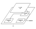
- FIG. 12 shows an example in which the semiconductor chip 900 (or 1000) of the image pickup apparatus 800 is formed as a two-layer structure laminated image sensor 1200 in which the semiconductor chips 900 (or 1000) are laminated in three layers.
- the pixel portion 1211 is formed on the semiconductor chip 1201 of the first layer
- the memory portion 1212 is formed on the semiconductor chip 1202 of the second layer
- the logic portion 1213 is formed on the semiconductor chip 1203 of the third layer.
- the pixel unit 1211 includes at least the pixel array in the sensor unit 802.
- the logic unit 1213 includes, for example, a sensor control unit 803, a recognition processing unit 804, a visual recognition processing unit 806, an output control unit 807, and an interface for communicating between the image pickup device 800 and the outside.
- the logic unit 1213 further includes a part or all of the drive circuit for driving the pixel array in the sensor unit 802.
- the memory unit 1212 may further include, for example, a memory used by the visual recognition processing unit 806 for processing image data, in addition to the memory 805.
- the image sensor 800 is formed by bonding the semiconductor chip 1201 of the first layer, the semiconductor chip 1202 of the second layer, and the semiconductor chip 1203 of the third layer while electrically contacting each other. It is configured as one solid-state image sensor.
- FIG. 13 shows a configuration example of the sensor unit 802.
- the illustrated sensor unit 802 includes a pixel array unit 1301, a vertical scanning unit 1302, an AD (Analog to Digital) conversion unit 1303, a horizontal scanning unit 1304, a pixel signal line 1305, a vertical signal line VSL, and a control unit. It includes 1306 and a signal processing unit 1307.
- the control unit 1306 and the signal processing unit 1307 in FIG. 13 may be included in the sensor control unit 803 in FIG. 8, for example.
- the pixel array unit 1301 is composed of a plurality of pixel circuits 1310 including a photoelectric conversion element that performs photoelectric conversion on the received light and a circuit that reads out charges from the photoelectric conversion element.
- the plurality of pixel circuits 1310 are arranged in a matrix arrangement in the horizontal direction (row direction) and the vertical direction (column direction).
- the line in the row direction of the pixel circuit 1310 is a line. For example, when an image of one frame is formed by 1920 pixels ⁇ 1080 lines, the pixel array unit 1301 forms an image of one frame by a pixel signal obtained by reading out a line consisting of 1920 pixel circuits 1310 by 1080 lines. To.
- the pixel signal line 1305 is connected to each row and column of each pixel circuit 1310, and the vertical signal line VSL is connected to each column.
- the end portion of each pixel signal 1305 that is not connected to the pixel array unit 1301 is connected to the vertical scanning unit 1302.
- the vertical scanning unit 1302 transmits a control signal such as a drive pulse for reading a pixel signal from the pixels to the pixel array unit 1301 via the pixel signal line 1305 under the control of the control unit 1306.
- the end portion of the vertical signal line VSL that is not connected to the pixel array unit 1301 is connected to the AD conversion unit 1303.
- the pixel signal read from the pixels is transmitted to the AD conversion unit 1303 via the vertical scanning line VSL.
- the reading of the pixel signal from the pixel circuit 1310 is performed by transferring the charge accumulated in the photoelectric conversion element due to exposure to the floating diffusion layer (FD) and converting the transferred charge in the floating diffusion layer into a voltage. Will be done.
- the voltage converted from the electric charge in the floating diffusion layer is output to the vertical signal line VSL via an amplifier.
- the AD conversion unit 1303 includes a column AD converter (ADC) 1311 provided for each vertical signal line VSL, a reference signal generation unit 1312, and a horizontal scanning unit 1304.
- the column AD converter 1311 is a column AD converter that performs AD conversion processing on each column of the pixel array unit 1301, and AD converts the pixel signal supplied from the pixel circuit 1310 via the vertical signal line VSL.
- the processing is performed to generate two digital values for the correlated double sampling (CDS) processing for noise reduction, and output to the signal processing unit 1307.
- CDS correlated double sampling
- the reference signal generation unit 1312 generates a lamp signal as a reference signal used by each column AD converter 1311 to convert the pixel signal into two digital values based on the control signal from the control unit 1306, and generates each column AD. It is supplied to the converter 1311.
- the lamp signal is a signal in which the voltage level drops with a constant slope with respect to time, or a signal in which the voltage level drops stepwise.
- the column AD converter 1311 when a lamp signal is supplied, counting is started according to the clock signal by the counter, and the voltage of the pixel signal supplied from the vertical signal line VSL is compared with the voltage of the lamp signal to compare the lamp signal. The count by the counter is stopped at the timing when the voltage of the above crosses the voltage of the pixel signal, and the value corresponding to the count value at that time is output to convert the pixel signal which is an analog signal into a digital value.
- the signal processing unit 1307 performs CDS processing based on the two digital values generated by the column AD converter 1311, generates a pixel signal (pixel data) of the digital signal, and outputs it to the outside of the sensor control unit 803.
- the horizontal scanning unit 1304 temporarily holds the digital value of each column AD converter 1311 by performing a selection operation of selecting the column AD converters 1311 in a predetermined order under the control of the control unit 1306. Are sequentially output to the signal processing unit 1307.
- the horizontal scanning unit 1304 is configured by using, for example, a shift register or an address decoder.
- the control unit 1306 drives the vertical scanning unit 1302, the AD conversion unit 1303, the reference signal generation unit 1312, the horizontal scanning unit 1304, and the like based on the image pickup control signal supplied from the sensor control unit 803. Generates a signal and outputs it to each part. For example, the control unit 1306 generates a control signal for the vertical scanning unit 1302 to supply to each pixel circuit 1310 via the pixel signal line 1305 based on the vertical synchronization signal and the horizontal synchronization signal included in the image pickup control signal. And supplies to the vertical scanning unit 1302. Further, the control unit 1306 passes information indicating the analog gain included in the image pickup control signal to the AD conversion unit 1303. In the AD conversion unit 1303, the gain of the pixel signal input to each column AD converter 1311 via the vertical signal line VSL is controlled based on the information indicating the analog gain.
- the vertical scanning unit 1302 Based on the control signal supplied from the control unit 1306, the vertical scanning unit 1302 transmits various signals including drive pulses to the pixel signal line 1305 of the selected pixel industry of the pixel array unit 1301 for each pixel circuit 1310. And output the pixel signal from each pixel circuit 1310 to the vertical signal line VSL.
- the vertical scanning unit 1302 is configured by using, for example, a shift register, an address decoder, or the like. Further, the vertical scanning unit 1302 controls the exposure in each pixel circuit 1310 based on the information indicating the exposure supplied from the control unit 1306.
- the sensor unit 802 configured as shown in FIG. 13 is a column AD type image sensor in which each column AD converter 1311 is arranged for each column.
- the configuration of the image pickup apparatus 800 with an image recognition function has been described with reference to FIGS. 8 to 13.
- the model used by the recognition processing unit 804 is learned by using the learning data set.
- the recognition rate is lower than that of the data of other attributes.
- FIG. 14 shows an operation example in the learning phase for applying the image pickup device 800 with a recognition function to the image classification service in the form of a flowchart.
- step S1401 the original data set is input, and with respect to the data having a minority attribute, additional data is generated according to the above equation (2) or (4) by the Adversary Exchange (step S1401).
- the recognition processing unit 804 trains the model using the original data set and the additional data set (step S1402).
- the model trained in this way can improve the recognition rate even for minority attributes and perform image classification while ensuring fairness.
- FIG. 15 schematically shows an example of a functional configuration of the in-vehicle camera 1500.
- the illustrated in-vehicle camera 1500 includes a lens 1501, an image sensor 1502, a signal processing unit 1503, a recognition unit 1504, and a control unit 1505.
- the image sensor 1502 is configured by using an element such as CMOS, and captures an image formed on the imaging surface by the lens 1501.
- the signal processing unit 1503 performs signal processing on the RAW data output from the image sensor 1502.
- the signal processing performed by the signal processing 1503 corresponds to, for example, demosaication, noise reduction, white balance adjustment, gamma correction, sensor spectral correction, YC conversion, and the like.
- the recognition unit 1504 recognizes an object included in the captured image after processing by the signal processing unit 1503.
- the recognition unit 1504 recognizes various objects such as a motorcycle, a bicycle, a pedestrian, a road sign, a traffic light, a lane, a median strip, a guardrail, a roadside tree, and a street light.
- the recognition unit 1504 performs object recognition processing using a trained model configured by a neural network or the like.
- the control unit 1505 comprehensively controls the operation of each unit in the in-vehicle camera 1500.
- the control unit 1505 controls, for example, an image pickup operation in the image sensor 1502 and signal processing in the signal processing unit 1503. Further, the control unit 1505 may add, delete, or change an object to be recognized by the recognition unit 1504.
- the vehicle control referred to here is for automatic driving such as inter-vehicle control (ACC), lane departure warning (LDW), lane keep assist (LKA), automatic emergency braking (AEB), blind spot detection (BSD), or ADAS.
- Vehicle control, as well as drive control of each drive unit such as active cornering light (ACL), brake actuator (BRK), and steering device (STR).
- FIG. 16 shows an example of the internal configuration of the image sensor 1502 and the signal processing unit 1503.
- the image sensor 1502 includes a shutter 1601, an element unit 1602, and an analog gain processing unit 1603.
- the light collected by the lens 1501 passes through the shutter 1601 and reaches the image pickup surface of the element unit 1602.
- the element unit 1602 is composed of a two-dimensional pixel array, and a pixel signal corresponding to the amount of received light is output from each pixel. Each pixel signal is amplified in the analog region by the analog gain processing unit 1603, then digitally converted and output to the signal processing unit 1603.
- the signal processing unit 1603 includes a development processing unit 1604, a detection unit 1605, and a comparison unit 1606.
- the development processing unit 1604 performs development processing including digital gain processing and gamma processing on the digital pixel signal output from the image sensor 1502.
- the detection unit 1605 detects the entire screen imaged by the image sensor 1502 by OPD (Optical Detection) and detects the brightness (brightness) of the screen.
- the comparison unit 1606 compares the brightness of the entire screen detected by the detection unit 1605 with a predetermined reference value (Ref).
- the control unit 1505 controls the opening / closing timing (that is, the exposure time) of the shutter 1601 and adjusts the analog gain of the analog gain processing unit 303 based on the difference between the screen brightness output from the comparison unit 1606 and the reference value.
- the digital gain and other development parameters in the development processing unit 1604 are adjusted to control the captured image of the image sensor 1502 to have an appropriate brightness.
- the in-vehicle camera 1500 does not necessarily aim to capture an image observed by a user (driver or the like), but mainly aims to acquire image information that can be used by the vehicle control system 1510 in the subsequent stage. Therefore, the development processing performed by the signal processing unit 1503 of the vehicle-mounted camera 1500 does not have to be the same as that of the image pickup apparatus 800.
- the in-vehicle camera 1500 is equipped with an object recognition function, and recognizes various objects such as motorcycles, bicycles, pedestrians, road signs, traffic lights, lanes, medians, guardrails, roadside trees and street lights.
- the model used by the recognition unit 1504 is pre-trained using the training data set. Here, it is assumed that sufficient learning cannot be performed on the data of the minority attribute contained in the original data set, and the recognition rate is lower than that of the data of other attributes.
- the model used in the recognition unit 1504 is trained to recognize humans, but there is an imbalance in the amount of data between the images of children and adults, and the recognition rate of children with a small number of training data is low. Is assumed.
- an image recognized as a child by the model used by the recognition unit 1504 is generated by the Adversary Exchange, and the image is added to perform the image to improve the recognition rate of the child. It becomes possible to perform the learning of.
- FIG. 17 shows an operation example in the form of a flowchart for training to recognize a human in the learning phase of the recognition unit 1504 of the in-vehicle camera 1500.
- step S1701 the original data set is input, and for the image of a child with a small number of samples, additional data is generated according to the above equation (2) or (4) by the Advanced Annual Exchange (step S1701).
- the recognition unit 1504 trains the model using the original data set and the additional data set (step S1702).
- the model learned in this way can improve the recognition rate even for the image of a child, and can perform recognition while ensuring fairness for human beings in general.
- a trained model can recognize and process endoscopic images to support surgery. Based on the recognition results of the trained model, the doctor can properly proceed with the surgery and control the movement of the surgical robot.
- FIG. 18 shows a configuration example of a medical robot device 1800 using a robot arm.
- the medical robot device 1800 includes a robot arm 1810 and a control device 1820 that controls the operation of the robot arm 1810.
- the robot arm 1810 includes one or a plurality of robot arms composed of a multi-link structure in which a plurality of links are connected by a joint axis.
- a joint axis In FIG. 18, only one robot arm is drawn for the sake of simplification of the drawing.
- an endoscope, forceps, a pneumoperitoneum tube, an energy treatment tool, a sword, a retractor, and other medical surgical tools are mounted.
- the control device 1820 includes an image recognizer 1821 and a motion predictor 1822.
- the image recognizer 1821 recognizes an image captured by an endoscope. Further, the motion predictor 1822 predicts the motion of the robot arm of the robot arm 1810 according to the recognition result of the image recognizer 1821.
- the control device 1820 is input with an image captured by the surgical site by the endoscope, motion information of the robot arm from the robot arm 1810, and sensor information of the robot arm.
- the motion information of the robot arm is measured by the position, speed, acceleration, and posture of each joint of the robot arm (encoder installed on the rotation axis of the joint) of medical equipment such as an endoscope supported by the tip of the robot arm. Includes information on the joint angle).
- the sensor information of the robot arm includes information such as acceleration measured by an IMU (Inertial Measurement Unit) mounted on the robot arm 1810, torque information acting on each joint, and medical treatment supported by the tip of the robot arm. Information such as external force acting on the equipment is included.
- the image recognizer 1821 uses a model trained to perform image recognition to recognize an image of a medical device included in an image captured by the endoscope or the environment in the field of view of the endoscope, and the device is used. Output recognition information and environment recognition information.
- the image recognizer 1821 performs user-specific model learning in the field using the captured image of the endoscope, and further performs image recognition specialized to the user's needs using the trained model. ..
- the image recognizer 1821 uses the type of medical device recognized in the field of the endoscope (for example, forceps, abdominal tube, energy treatment tool, sword, retractor, etc.) and the position and posture of each device as device recognition information. , Recognize the operating state (for example, open / closed state for forceps, energy output state for energy treatment tool). Further, the image recognizer 1821 uses the depth information (including the shape of the organ and the instrument) of the organ and the medical instrument included in the captured image in the field of the endoscope as the environment recognition information, and the environmental map in the surgical department.
- the type of medical device recognized in the field of the endoscope for example, forceps, abdominal tube, energy treatment tool, sword, retractor, etc.
- the position and posture of each device as device recognition information.
- Recognize the operating state for example, open / closed state for forceps, energy output state for energy treatment tool.
- the image recognizer 1821 uses the depth information (including the shape of the organ and the instrument) of the organ and the medical
- the image recognizer 1821 recognizes, for example, each object such as an organ or a medical instrument included in the image of the surgical site, a material thereof, depth information of each object, and an environmental map as environment recognition information.
- the motion predictor 1822 uses a model learned to predict the motion of the robot arm from the image recognition result, and uses the recognition information of the instrument recognition information and the environment recognition information to provide target command related information to the robot arm 1810. Predict and output.
- the motion predictor 1822 uses, for example, the camera target position of the endoscope, the posture, the velocity, the acceleration, the gazing point, the line-of-sight vector (object position, distance, vector posture), the electronic cutting position of the captured image, as information related to the target command. Predict various target command values such as distance. Further, the motion predictor 1822 predicts the target position, posture, velocity, acceleration, and operating force of the device as the target command-related information.
- control device 1820 performs an inverse kinematics calculation based on the information of the target position, posture, speed, and acceleration of the medical device supported by the tip of the robot arm such as the endoscope predicted by the motion predictor 1822.
- the target joint angle, joint angular velocity, and joint angular acceleration of each joint of the robot arm are calculated, and the command value for the robot arm 1810 is output.
- the model used in the image recognizer 1821 is pre-learned using a learning data set so that instrument information and environmental information can be recognized from the endoscopic image.
- a learning data set so that instrument information and environmental information can be recognized from the endoscopic image.
- the recognition rate is lower than that of the data of other attributes.
- learning data many images of successful cases are provided, but few images of unsuccessful cases.
- an image recognized by the image recognizer 1821 as a failure example is generated by the Advanced Single, and the image is added to perform an image to learn a model with improved recognition accuracy. Will be possible.
- FIG. 19 shows an operation example in the form of a flowchart for training to recognize an endoscopic image in the learning phase of the image recognizer 1821.
- step S1901 the original data set is input, and for the image of the failure example with a small number of samples, additional data is generated according to the above equation (2) or (4) by the Adversary Exchange (step S1901).
- the image recognizer 1821 trains the model using the original data set and the additional data set (step S1902).
- the model learned in this way can improve the recognition rate even for the image of the failed example, and can perform recognition while ensuring fairness for the endoscopic image in general.
- the present disclosure can be applied mainly to the learning of a machine learning model for image classification, and the machine learning model to which the present disclosure is applied can be mounted on, for example, an image pickup device.
- the machine learning model to which the present disclosure is applied can be used for a recognizer of an in-vehicle camera, image recognition of an operating part in the medical field, and the like.
- An acquisition unit that acquires information on the bias of training data used for model training, and A generation unit that generates additional learning data from the data included in the training data based on the information regarding the bias.
- a learning unit that learns the model using the learning data and the additional learning data, Information processing device equipped with.
- the acquisition unit acquires information indicating a minority of the attributes of the first learning data.
- the data generation unit generates a second learning data of the same attribute from the data of the minority attribute included in the first learning data.
- the data generation unit generates an Adversarial Example, which is the second learning data, from the data of the minority attribute included in the learning data.
- the information processing apparatus according to any one of (1) and (2) above.
- the data generation unit generates an Advanced Example based on the Fast Gradient Sign Method.
- the information processing device according to (3) above.
- the data generation unit generates a second learning data by superimposing noise on the data included in the learning data.
- the information processing apparatus according to any one of (1) to (4) above.
- a data holding unit that holds the first learning data used for learning a machine learning model
- Acquisition unit that acquires information on the bias of the learning data
- a data generation unit that generates a second learning data using the data included in the learning data based on the information regarding the bias.
- a learning unit that learns the machine learning model using the first learning data and the second learning data.
- An image pickup unit that captures an image and A recognition unit that recognizes the captured image using a machine learning model, Equipped with Based on the information regarding the bias of the learning data for learning the machine learning model, the learning data is generated using the data included in the learning data, and the machine learning is generated using the generated learning data. Learn the model, Imaging device.
- Training data is generated using a small number of image data depending on the field to which the imaging device is applied among the learning data, and the machine learning model is generated using the generated learning data. learn, The image pickup apparatus according to (8) above.
- a recognition unit that recognizes the captured image using a machine learning model, and Equipped with Based on the information regarding the bias of the learning data for learning the machine learning model, the learning data is generated by using the data included in the learning data, and the machine learning is generated by using the generated learning data.
- An imager that learns the model and Vehicle equipment with.
- An imaging unit that captures an image of the area around the surgical site
- a recognition unit that recognizes the captured image using a machine learning model, Equipped with Based on the information regarding the bias of the learning data for learning the machine learning model, the learning data is generated by using the data included in the learning data, and the machine learning is generated by using the generated learning data.
- An imager that learns the model and Medical robot device equipped with.
Landscapes
- Engineering & Computer Science (AREA)
- Health & Medical Sciences (AREA)
- Theoretical Computer Science (AREA)
- Medical Informatics (AREA)
- General Health & Medical Sciences (AREA)
- General Physics & Mathematics (AREA)
- Physics & Mathematics (AREA)
- Multimedia (AREA)
- Surgery (AREA)
- Software Systems (AREA)
- Life Sciences & Earth Sciences (AREA)
- Public Health (AREA)
- Artificial Intelligence (AREA)
- Evolutionary Computation (AREA)
- Biomedical Technology (AREA)
- Computing Systems (AREA)
- Computer Vision & Pattern Recognition (AREA)
- Nuclear Medicine, Radiotherapy & Molecular Imaging (AREA)
- Databases & Information Systems (AREA)
- Veterinary Medicine (AREA)
- Robotics (AREA)
- Molecular Biology (AREA)
- Animal Behavior & Ethology (AREA)
- Heart & Thoracic Surgery (AREA)
- Primary Health Care (AREA)
- Epidemiology (AREA)
- General Business, Economics & Management (AREA)
- Business, Economics & Management (AREA)
- Urology & Nephrology (AREA)
- Data Mining & Analysis (AREA)
- General Engineering & Computer Science (AREA)
- Mathematical Physics (AREA)
- Image Analysis (AREA)
Priority Applications (2)
| Application Number | Priority Date | Filing Date | Title |
|---|---|---|---|
| US18/255,170 US20240005643A1 (en) | 2020-12-09 | 2021-10-14 | Information processing apparatus, information processing method, computer program, imaging device, vehicle device, and medical robot device |
| JP2022568081A JP7732466B2 (ja) | 2020-12-09 | 2021-10-14 | 情報処理装置及び情報処理方法、コンピュータプログラム、撮像装置、車両装置、並びに医療用ロボット装置 |
Applications Claiming Priority (2)
| Application Number | Priority Date | Filing Date | Title |
|---|---|---|---|
| JP2020-204550 | 2020-12-09 | ||
| JP2020204550 | 2020-12-09 |
Publications (1)
| Publication Number | Publication Date |
|---|---|
| WO2022123907A1 true WO2022123907A1 (ja) | 2022-06-16 |
Family
ID=81973531
Family Applications (1)
| Application Number | Title | Priority Date | Filing Date |
|---|---|---|---|
| PCT/JP2021/038146 Ceased WO2022123907A1 (ja) | 2020-12-09 | 2021-10-14 | 情報処理装置及び情報処理方法、コンピュータプログラム、撮像装置、車両装置、並びに医療用ロボット装置 |
Country Status (3)
| Country | Link |
|---|---|
| US (1) | US20240005643A1 (https=) |
| JP (1) | JP7732466B2 (https=) |
| WO (1) | WO2022123907A1 (https=) |
Cited By (3)
| Publication number | Priority date | Publication date | Assignee | Title |
|---|---|---|---|---|
| WO2024058202A1 (ja) * | 2022-09-15 | 2024-03-21 | ソニーグループ株式会社 | 情報処理装置及び情報処理方法、並びにコンピュータプログラム |
| WO2024166331A1 (ja) | 2023-02-09 | 2024-08-15 | 富士通株式会社 | 機械学習プログラム、方法、及び装置 |
| WO2024180802A1 (ja) * | 2023-02-27 | 2024-09-06 | ソニーグループ株式会社 | 情報処理装置及び情報処理方法、コンピュータプログラム、並びにイメージセンサ |
Families Citing this family (3)
| Publication number | Priority date | Publication date | Assignee | Title |
|---|---|---|---|---|
| US20230377368A1 (en) * | 2022-05-23 | 2023-11-23 | Lemon Inc. | Using augmented face images to improve facial recognition tasks |
| WO2024127411A1 (en) * | 2022-12-15 | 2024-06-20 | Fractal Analytics Private Limited | Systems and methods for responsible ai |
| JP7726226B2 (ja) * | 2023-01-27 | 2025-08-20 | トヨタ自動車株式会社 | 情報処理装置 |
Citations (6)
| Publication number | Priority date | Publication date | Assignee | Title |
|---|---|---|---|---|
| JP2019076699A (ja) * | 2017-10-26 | 2019-05-23 | 株式会社日立製作所 | 偽陽性低減での小結節検出 |
| US20190262084A1 (en) * | 2018-02-27 | 2019-08-29 | NavLab, Inc. | Artificial intelligence guidance system for robotic surgery |
| JP2019200769A (ja) * | 2018-05-14 | 2019-11-21 | パナソニックIpマネジメント株式会社 | 学習装置、学習方法及びプログラム |
| US20200250304A1 (en) * | 2019-02-01 | 2020-08-06 | Nec Laboratories America, Inc. | Detecting adversarial examples |
| JP6779491B1 (ja) * | 2019-06-25 | 2020-11-04 | 株式会社エクサウィザーズ | 文字認識装置、撮影装置、文字認識方法、および、文字認識プログラム |
| JP2020534594A (ja) * | 2017-09-21 | 2020-11-26 | インターナショナル・ビジネス・マシーンズ・コーポレーションInternational Business Machines Corporation | 画像分類タスクの機械学習を実施するためのコンピュータ実装方法、コンピュータ・プログラム製品、およびコンピュータ処理システム、ならびに自動車のための先進運転者支援システム |
Family Cites Families (6)
| Publication number | Priority date | Publication date | Assignee | Title |
|---|---|---|---|---|
| KR20210010284A (ko) * | 2019-07-18 | 2021-01-27 | 삼성전자주식회사 | 인공지능 모델의 개인화 방법 및 장치 |
| US11769180B2 (en) * | 2019-10-15 | 2023-09-26 | Orchard Technologies, Inc. | Machine learning systems and methods for determining home value |
| US10783401B1 (en) * | 2020-02-23 | 2020-09-22 | Fudan University | Black-box adversarial attacks on videos |
| US11586983B2 (en) * | 2020-03-02 | 2023-02-21 | Nxp B.V. | Data processing system and method for acquiring data for training a machine learning model for use in monitoring the data processing system for anomalies |
| US11475331B2 (en) * | 2020-06-25 | 2022-10-18 | International Business Machines Corporation | Bias source identification and de-biasing of a dataset |
| US20220101146A1 (en) * | 2020-09-25 | 2022-03-31 | Affectiva, Inc. | Neural network training with bias mitigation |
-
2021
- 2021-10-14 US US18/255,170 patent/US20240005643A1/en active Pending
- 2021-10-14 JP JP2022568081A patent/JP7732466B2/ja active Active
- 2021-10-14 WO PCT/JP2021/038146 patent/WO2022123907A1/ja not_active Ceased
Patent Citations (6)
| Publication number | Priority date | Publication date | Assignee | Title |
|---|---|---|---|---|
| JP2020534594A (ja) * | 2017-09-21 | 2020-11-26 | インターナショナル・ビジネス・マシーンズ・コーポレーションInternational Business Machines Corporation | 画像分類タスクの機械学習を実施するためのコンピュータ実装方法、コンピュータ・プログラム製品、およびコンピュータ処理システム、ならびに自動車のための先進運転者支援システム |
| JP2019076699A (ja) * | 2017-10-26 | 2019-05-23 | 株式会社日立製作所 | 偽陽性低減での小結節検出 |
| US20190262084A1 (en) * | 2018-02-27 | 2019-08-29 | NavLab, Inc. | Artificial intelligence guidance system for robotic surgery |
| JP2019200769A (ja) * | 2018-05-14 | 2019-11-21 | パナソニックIpマネジメント株式会社 | 学習装置、学習方法及びプログラム |
| US20200250304A1 (en) * | 2019-02-01 | 2020-08-06 | Nec Laboratories America, Inc. | Detecting adversarial examples |
| JP6779491B1 (ja) * | 2019-06-25 | 2020-11-04 | 株式会社エクサウィザーズ | 文字認識装置、撮影装置、文字認識方法、および、文字認識プログラム |
Non-Patent Citations (3)
| Title |
|---|
| "The Basics of AI Every Engineer Needs to Know: Easy Explanation of Machine Learning, Statistics, and Algorithms", 21 January 2019, IMPRESS CORPORATION, Tokyo, JP, ISBN: 978-4-295-00535-3, article UMEDA, HIROYUKI: "Chapter 6: Transfer learning and overfitting", pages: 80 - 84, XP009538153 * |
| INOUE TOSHIAKI: "A scene recognition method using dashcams for reducing traffic accident risks", PIONEER R&D, 31 October 2020 (2020-10-31), XP055940880, Retrieved from the Internet <URL:https://global.pioneer/en/strengths/crdl/rd/pdf/2020-1.pdf> * |
| SUN SINING, YEH CHING-FENG, OSTENDORF MARI, HWANG MEI-YUH, XIE LEI: "Training Augmentation with Adversarial Examples for Robust Speech Recognition", 17 June 2018 (2018-06-17), XP055886876, Retrieved from the Internet <URL:https://arxiv.org/pdf/1806.02782.pdf> [retrieved on 20220203] * |
Cited By (3)
| Publication number | Priority date | Publication date | Assignee | Title |
|---|---|---|---|---|
| WO2024058202A1 (ja) * | 2022-09-15 | 2024-03-21 | ソニーグループ株式会社 | 情報処理装置及び情報処理方法、並びにコンピュータプログラム |
| WO2024166331A1 (ja) | 2023-02-09 | 2024-08-15 | 富士通株式会社 | 機械学習プログラム、方法、及び装置 |
| WO2024180802A1 (ja) * | 2023-02-27 | 2024-09-06 | ソニーグループ株式会社 | 情報処理装置及び情報処理方法、コンピュータプログラム、並びにイメージセンサ |
Also Published As
| Publication number | Publication date |
|---|---|
| US20240005643A1 (en) | 2024-01-04 |
| JP7732466B2 (ja) | 2025-09-02 |
| JPWO2022123907A1 (https=) | 2022-06-16 |
Similar Documents
| Publication | Publication Date | Title |
|---|---|---|
| JP7732466B2 (ja) | 情報処理装置及び情報処理方法、コンピュータプログラム、撮像装置、車両装置、並びに医療用ロボット装置 | |
| JP6638851B1 (ja) | 撮像装置、撮像システム、撮像方法および撮像プログラム | |
| EP3515057B1 (en) | Image pickup device and electronic apparatus | |
| JP7386792B2 (ja) | 電子機器及び固体撮像装置 | |
| CN111382670A (zh) | 使用驾驶员注意力信息的语义分割 | |
| JP7667962B2 (ja) | 情報処理装置、情報処理システム、情報処理方法、及び情報処理プログラム | |
| US10735660B2 (en) | Method and device for object identification | |
| US20240089577A1 (en) | Imaging device, imaging system, imaging method, and computer program | |
| TW202125441A (zh) | 安全警示語音提示方法 | |
| US12094222B2 (en) | Cabin monitoring and situation understanding perceiving method and system thereof | |
| CN114008698A (zh) | 外部环境识别装置 | |
| Fiani et al. | Keeping eyes on the road: Understanding driver attention and its role in safe driving | |
| US20240078803A1 (en) | Information processing apparatus, information processing method, computer program, and sensor apparatus | |
| US20230308779A1 (en) | Information processing device, information processing system, information processing method, and information processing program | |
| WO2022019025A1 (ja) | 情報処理装置、情報処理システム、情報処理方法、及び情報処理プログラム | |
| US20250209799A1 (en) | Information processing device, information processing method, and computer program | |
| CN113966526A (zh) | 外部环境识别装置 | |
| Rizan et al. | Guided vision: a high efficient and low latent Mobile app for visually impaired | |
| US12146789B2 (en) | Sensor device and method for operating a sensor device |
Legal Events
| Date | Code | Title | Description |
|---|---|---|---|
| 121 | Ep: the epo has been informed by wipo that ep was designated in this application |
Ref document number: 21903011 Country of ref document: EP Kind code of ref document: A1 |
|
| ENP | Entry into the national phase |
Ref document number: 2022568081 Country of ref document: JP Kind code of ref document: A |
|
| WWE | Wipo information: entry into national phase |
Ref document number: 18255170 Country of ref document: US |
|
| NENP | Non-entry into the national phase |
Ref country code: DE |
|
| 122 | Ep: pct application non-entry in european phase |
Ref document number: 21903011 Country of ref document: EP Kind code of ref document: A1 |