WO2022123749A1 - 解算出方法、解算出装置及びプログラム - Google Patents
解算出方法、解算出装置及びプログラム Download PDFInfo
- Publication number
- WO2022123749A1 WO2022123749A1 PCT/JP2020/046147 JP2020046147W WO2022123749A1 WO 2022123749 A1 WO2022123749 A1 WO 2022123749A1 JP 2020046147 W JP2020046147 W JP 2020046147W WO 2022123749 A1 WO2022123749 A1 WO 2022123749A1
- Authority
- WO
- WIPO (PCT)
- Prior art keywords
- start point
- optical
- path
- end point
- zero
- Prior art date
- Legal status (The legal status is an assumption and is not a legal conclusion. Google has not performed a legal analysis and makes no representation as to the accuracy of the status listed.)
- Ceased
Links
Images



Classifications
-
- H—ELECTRICITY
- H04—ELECTRIC COMMUNICATION TECHNIQUE
- H04B—TRANSMISSION
- H04B10/00—Transmission systems employing electromagnetic waves other than radio-waves, e.g. infrared, visible or ultraviolet light, or employing corpuscular radiation, e.g. quantum communication
- H04B10/27—Arrangements for networking
Definitions
- the present invention relates to a solution calculation method, a solution calculation device, and a program.
- Optical networks that use optical fibers as transmission lines are known, and are often used in backbone networks such as backbone networks. Since a large amount of data flows in a backbone network, a technique called optical wavelength division multiplexing (WDM) is often used for the purpose of increasing the communication capacity.
- WDM optical wavelength division multiplexing
- This technology utilizes the fact that optical signals of different wavelengths do not interfere with each other, and by passing multiple optical signals of different wavelengths within the same optical fiber, it is as if many transmission lines are connected between the points connected by the optical fiber. It is possible to perform data communication as if it were there.
- An optical network can be regarded as a directed graph in graph theory if a node at each point and each optical fiber connecting one node to another are abstracted as a link (or an edge).
- a path connecting two nodes using one light wavelength via one or more links is also referred to as a light path.
- connection request that is, a request indicating the start point and end point node pair for which communication is to be established and the request indicating how many optical paths the node pair requires
- RWA Routing and Wavelength Assignment Problem
- the optical wavelength allocation problem is an important problem for measuring the performance of an optical network and finding how to allocate an optical path to bring out its performance, but it is generally known that it is a difficult problem for NP. Therefore, it is difficult to efficiently find the optimum solution for every instance. Therefore, many methods for solving the optical wavelength allocation problem approximately have been proposed.
- Non-Patent Document 3 describes a method capable of obtaining a solution that seems to be considerably close to the optimum solution by using the framework of Branch-and-price.
- the conventional method for solving the optical wavelength allocation problem mainly has the following two problems.
- the first is that there is no guarantee about the approximation accuracy of the method for finding an approximate solution. For example, for a method that uses heuristics or a method that limits the number of paths considered for a node pair, how bad the solution obtained by that method is compared to the true optimal solution, that is, how small the number of lights is. There is no guarantee that only the path has been assigned.
- the second point is that it is difficult to incorporate the detailed restrictions that appear in reality. In particular, for example, it is difficult to incorporate such a constraint in a method using a column generation method or the like. Therefore, various restrictions that actually exist (for example, restrictions such as suppressing the number of hops to a certain number or less, not allocating two or more wavelengths to the same path, etc.) cannot be considered.
- One embodiment of the present invention has been made in view of the above points, and an object thereof is to calculate a solution of an optical wavelength allocation problem that can consider various restrictions and guarantees approximation accuracy. do.
- the solution calculation method is a solution calculation method for calculating the solution of the optical wavelength allocation problem on the optical network, and is between the start point sk and the end point tk of the optical network.
- a solution calculation device 10 capable of considering various fine restrictions that appear in reality and calculating a solution of an optical wavelength allocation problem with a guarantee for approximation accuracy will be described.
- the number of hops the number of optical fibers that pass through communication
- two or more wavelengths are not assigned to the same path, and the like.
- V (V, E) representing the optical network and the number of wavelengths ⁇ that can be used by the WDM technology are given.
- V is a set of nodes representing each point of the optical network
- E is a set of links connecting the nodes.
- the node pair (sk, tk) ⁇ V ⁇ V of the start point and the end point for which communication is to be established, and the number of optical paths d k ⁇ Z > 0 to be assigned from the start point sk to the end point tk are given.
- k 1, ..., K.
- Z > 0 is a set of all integers of 1 or more.
- the node pair of the start point and the end point is also referred to as a "start point end point pair”.
- the number of optical paths that you want to assign from the start point to the end point is also called "demand”.
- the optical wavelength allocation problem can be formulated as the following maximization problem.
- m k is a variable indicating how many optical paths are assigned between ( sk, tk )
- c i ⁇ k is a path of pi k and a wavelength of ⁇ ⁇ ⁇ 1, ..., ⁇ . It is a variable indicating whether or not to assign an optical path.
- Equation (2) is a constraint that limits the number of optical paths assigned to the start point / end point pair ( sk , tk) to the number of demands d k .
- Equation (4) is an important constraint, that the optical path of wavelength ⁇ can use the link j only once.
- equation (5) is a constraint that expresses the relationship between the variables m k and ci ⁇ k .
- Equation 2 is a formulation by linear integer programming (ILP), and various other formulations can be considered.
- ILP linear integer programming
- the formulation shown in Equation 2 above is also exponentially large. It is an integer programming problem involving variables. Therefore, it is difficult to input the formulation shown in Equation 2 above into a commercially available integer programming solver as it is and solve it.
- a method for solving the optical wavelength allocation problem using heuristics for example, Non-Patent Document 1 and Non-Patent Document 2
- column generation for example, Column-and-price
- branch-and-price a framework called Branch-and-price
- a method for solving the light wavelength allocation problem for example, Non-Patent Document 3 and the like
- it is converted into a simpler integer programming problem and then by the integer programming solver.
- Techniques such as solving are also known.
- all of these conventional methods have problems that the approximation accuracy is not guaranteed and it is difficult to incorporate the detailed restrictions that appear in reality.
- the number of optical paths assigned by the solution calculated by the solution calculation device 10 according to the present embodiment is 1-1 / e ⁇ 0.632 times the number of optical paths assigned by the optimum solution. Is guaranteed not to get worse. It is also known that this approach requires a solution that is fairly close to the optimal solution in practice.
- the "greedy method for the submodular function maximization problem” refers to the following algorithm.
- BDD Binary Decision Diagram
- ZDD Zero-suppressed Binary Decision Diagram
- BDD and ZDD are data structures that can compactly represent a "combination set" such as a set of a plurality of paths. By holding all the routes between them that satisfy the detailed restrictions for each start point / end point pair (sk, tk ) as ZDD , each of these routes is held compactly compared to the actual number of routes. can do.
- the ZDD representing the set of paths between ( sk , tk) is efficiently constructed by a method called the frontier method. can do. Further, it is possible to easily add detailed restrictions to the ZDD by using the Apply operation described in Reference 2 and Reference 3 above. For example, the constraint that the number of hops is suppressed to H or less is realized by performing an Apply operation that takes the intersection of ZDD, which represents a set representing only combinations having H or less elements, and ZDD, which represents a set of routes. be able to.
- BDD and ZDD are data structures that represent a combination set with a loop-free directed acyclic graph (DAG) made up of a collection of nodes and oriented edges. Since BDD and ZDD have the same structure, they will be described together below.
- DAG directed acyclic graph
- BDD (and ZDD) is the terminal node
- first terminal node and “second terminal node”, respectively
- branch node There are no edges coming out of the first and second terminating nodes, and each branching node has two edges, a 0-branch and a 1-branch.
- the node pointed to by the 0-branch exiting this branch node v is called a 0-child node and is represented by lo (v).
- the node pointed to by the 1-branch exiting the branch node v is referred to as a 1-child node and is represented by hi (v).
- each branch node v is given an integer value label (v) ⁇ ⁇ 1, ..., C ⁇ called a label, which corresponds to the item number.
- An item is an element of a set that is the basis of a combination set (in this example, a set such as ⁇ a 1 , ..., a c ⁇ ).
- the label value is defined as c + 1.
- BDD (and ZDD) has a recursive structure in which the 0-branch or 1-branch from the branch node points to the BDD (or ZDD) node (branch node or terminal node) again.
- BDD v a certain BDD node v
- This BDD v means a BDD having a structure including a BDD node v and all BDD nodes that can be traced from this BDD node v.
- the BDD node at the top of the BDD (that is, the node with the smallest label value in the BDD) may be called "node V" or "BDD node V". .. That is, the BDD node and the BDD having this BDD node as the top node can be equated.
- ZDD there is only one top node in BDD and ZDD.
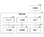
- FIG. 1 is a diagram showing an example of a hardware configuration of the solution calculation device 10 according to the present embodiment.
- the solution calculation device 10 is realized by a hardware configuration of a general computer or computer system, and includes an input device 101, a display device 102, an external I / F 103, and a communication I. It has a / F 104, a processor 105, and a memory device 106. Each of these hardware is communicably connected via the bus 107.
- the input device 101 is, for example, a keyboard, a mouse, a touch panel, or the like.
- the display device 102 is, for example, a display or the like.
- the solution calculation device 10 may not have, for example, at least one of the input device 101 and the display device 102.
- the external I / F 103 is an interface with an external device such as a recording medium 103a.
- the solution calculation device 10 can read or write the recording medium 103a via the external I / F 103.
- Examples of the recording medium 103a include a CD (Compact Disc), a DVD (Digital Versatile Disk), an SD memory card (Secure Digital memory card), a USB (Universal Serial Bus) memory card, and the like.
- the communication I / F 104 is an interface for connecting the solution calculation device 10 to the communication network.
- the processor 105 is, for example, various arithmetic units such as a CPU (Central Processing Unit) and a GPU (Graphics Processing Unit).
- the memory device 106 is, for example, various storage devices such as an HDD (Hard Disk Drive), an SSD (Solid State Drive), a RAM (Random Access Memory), a ROM (Read Only Memory), and a flash memory.
- the solution calculation device 10 can realize various processes described later.
- the hardware configuration shown in FIG. 1 is an example, and the solution calculation device 10 may have another hardware configuration.
- the solution calculation device 10 may have a plurality of processors 105 or a plurality of memory devices 106.
- FIG. 2 is a diagram showing an example of the functional configuration of the solution calculation device 10 according to the present embodiment.
- Z k is a set of paths between start point and end point pairs ( sk , tk) that satisfy a desired constraint. Each route is represented by a combination of links (optical fibers).
- the solution calculation device 10 has an input unit 201, a preprocessing unit 202, an optimization unit 203, and an output unit 204.
- Each of these functional units is realized, for example, by a process in which one or more programs installed in the solution calculation device 10 are executed by the processor 105.
- the preprocessing unit 202 enumerates a method of packing an optical path when only one wavelength ⁇ is used by using Z k input by the input unit 201. More precisely, the preprocessing unit 202 uses the Zk input by the input unit 201 to route the route so that when a plurality of start point / end point pairs are selected, the link is not covered between the start point / end point pairs. Exhaustively check whether it can be stretched. Then, the preprocessing unit 202 outputs a BDD R representing a set of combinations of start point / end point pairs that can be routed so that the link is not covered.
- the optimization unit 203 uses the R output from the preprocessing unit 202, the ZDD Zk input by the input unit 201, the demand dk , and the wavelength number ⁇ , by a greedy method for the submodular function maximization problem. Find out how to assign an optical path.
- the output unit 204 outputs the method of allocating the optical path obtained by the optimization unit 203.
- the output destination of the output unit 204 is not particularly limited and may be any output destination. Examples of such an output destination include a display, an auxiliary storage device, another device or device connected via a communication network, and the like.
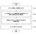
- FIG. 3 is a flowchart showing an example of the flow of processing for calculating the solution of the optical wavelength allocation problem.
- the preprocessing unit 202 uses the Z k input in step S101 above to obtain a BDD R representing a set of combinations of start point / end point pairs that can be routed so that the link is not covered (step S102). .. The details of the processing in this step will be described later.
- the optimization unit 203 uses the BDD R obtained in step S102 above, the ZDD Z k input in step S101 above, the demand d k , and the wavelength number ⁇ to maximize the submodular function.
- the method of allocating the optical path is obtained by the greedy method for (step S103). The details of the processing in this step will be described later.
- the output unit 204 outputs the method of assigning the optical path obtained in the above step S103 (step S104).
- the solution calculation device 10 can obtain a solution (method of allocating an optical path) of an optical wavelength allocation problem. Moreover, it is guaranteed that this solution will not be worse than 1-1 / e ⁇ 0.632 times the optimal solution. It is known that the greedy algorithm approach adopted in this embodiment requires a solution that is fairly close to the optimum solution in practice.
- the solution calculation device 10 can solve the optical wavelength allocation problem by incorporating the data structures of BDD and ZDD, incorporating the detailed restrictions that actually appear.
- FIG. 4 is a flowchart showing an example of a process flow for obtaining a combination of start point / end point pairs that can be routed so that the link is not covered.
- two or more optical paths are not assigned between the same start point / end point pair at one wavelength. If two or more optical paths may be assigned between the same start point / end point pair at one wavelength, input a plurality of ZDD Z k corresponding to the start point / end point pair ( sk , tk). It is feasible.
- the preprocessing unit 202 is set to R ⁇ ⁇ (step S201). That is, the preprocessing unit 202 initializes BDD R, which represents a set of combinations of start point / end point pairs that can be routed so that the link is not covered, into a set ⁇ that does not include any combination. Note that ⁇ means BDD representing a set ⁇ that does not include any combination.
- the Search procedure is a subroutine that takes the above d, Z representing a node of ZDD, and a subset S of ⁇ 1, ..., K ⁇ as arguments.
- the details of Search (d, Z, S) will be described later.
- the preprocessing unit 202 outputs the BDD R updated by the Search procedure in the above step S203 (step S204).
- This BDD R is a set of combinations of start point / end point pairs that can be routed so that the link is not covered.
- FIG. 5 is a diagram showing an example of Search (d, Z, S).
- This search procedure is based on a depth-first search, where S represents a set of numbers of start point / end point pairs currently pathing, and d represents the number of start point / end point pairs currently being focused on.
- the search is branched depending on whether or not d is added to the set S, that is, whether or not a route is established in the d-th start point / end point pair. Also, if it becomes impossible to create a route without using the same link during the search, the search will be terminated at that point.
- the preprocessing unit 202 ends the search procedure without doing anything (second to third lines).
- the preprocessing unit 202 first calculates the sum of the combination set represented by R and the power set of S by the Apply operation, and updates R with this sum (4 to 5). Line). Subsequently, the preprocessing unit 202 calls the UpdateTrack procedure and ends the Search procedure (lines 6 to 7).
- Powerset (S) is a subroutine that outputs a BDD node that represents a power set of S.
- the UpdateTrack procedure is a subroutine that takes S as an argument, and updates the variable T d that represents the BDD node.
- the Power set (S) will be omitted because it is easy to realize. On the other hand, the details of UpdateTrack (S) will be described later.
- the preprocessing unit 202 performs the processing on the eighth and subsequent lines. First, if the label of the BDD node T d is d, the preprocessing unit 202 substitutes hi (T d ) for T d + 1 (8th line), and substitutes T d for T d + 1 otherwise (9). Line), call the Search procedure recursively (line 10). The processing of the 8th to 10th lines corresponds to the search in the case of establishing a route to the d-th start point / end point pair.
- d + 1 is specified as the first argument of the Search procedure called on the 10th line
- the result of the DisjointJoin operation of Z and Z d is specified as the second argument
- the sum of S and ⁇ d ⁇ is specified as the third argument. ..
- the search of "whether the route can be established without using the same link" is realized.
- Reference 4 “Jun Kawahara, Toshiki Saitoh, Hirofumi Suzuki, and Ryo Yoshinaka. Solving the longest one-way ticket problem and enumerating letter graphs by augmenting the two representative approaches with ZDDs. . In Proceedings of Computational Intelligence in Information Systems Conference, pp. 294-305, 2016. "etc.
- the subsequent processing of the 11th to 15th lines corresponds to the search when the route is not established in the d-th start point / end point pair.
- the preprocessing unit 202 substitutes lo (T d ) for T d + 1 (11th line), and substitutes T d for T d + 1 otherwise (12). Line).
- T d + 1 is the first terminal node
- the preprocessing unit 202 ends the search procedure without performing any further search (lines 13 to 14).
- the condition that T d + 1 is the first terminal node means that a route can be established without covering any start point / end point pair after the d + 1th, so further search is required in this case. Because there is no such thing.
- the preprocessing unit 202 recursively calls the Search procedure if T d + 1 is not the first terminal node (line 15).
- d + 1 is specified as the first argument of the Search procedure called on the 15th line
- Z is specified as the second argument
- S is specified as the third argument.
- FIG. 6 is a diagram showing an example of UpdateTrack (S).
- This UpdateTrack procedure is a procedure for updating the variable Td representing the BDD node. Note that S is a subset of ⁇ 1, ..., K ⁇ .
- the preprocessing unit 202 substitutes R for T 1 (second line).
- R refers to the top node of BDD R.
- FIG. 7 is a flowchart showing an example of a flow of processing for obtaining a method of assigning an optical path by a greedy algorithm. This process is based on the greedy algorithm for the submodular function maximization problem, and the largest subset of start-end-end-end pairs whose demand is not yet satisfied can be routed without being linked. After obtaining it by a dynamic programming method, the wavelength ⁇ is assigned to the path between each start point / end point pair included in the subset, and this process is sequentially repeated one wavelength at a time.
- This Algorithm B is a procedure for finding the combination that maximizes the sum of the weights among the combinations included in the BDD R (that is, the combination of the start point and end point pairs) based on the dynamic programming method on R. As a result, a set can be established without covering the link among the start point / end point pairs whose demand is not yet satisfied, and a set having the maximum number of start point / end point pairs is obtained as S.
- step S330 the optimization unit 203 uses the route between the start point set pairs included in the start point end point pair set S obtained in step S320 above (however, the route is not linked to another route).
- the set Q of is obtained by the GetDisjointCombs procedure.
- GetDisjointCombs procedure is a subroutine that takes the above-mentioned start point / end point pair set S and ZDD Z 1 , ..., Z K as arguments.
- the details of GetDisjointCombs (S, Z 1 , ..., Z K ) will be described later.
- step S340 the optimization unit 203 assigns the wavelength ⁇ to each path included in the path set Q obtained in step S330.
- ⁇ 1, ..., ⁇ is obtained. It is a solution to the optical wavelength allocation problem and represents how to allocate optical paths.
- FIG. 8 is a diagram showing an example of GetDisjointCombs (S, Z 1 , ..., Z K ).
- This GetDisjointCombs procedure is a procedure for obtaining a set Q of routes that are not actually covered by links in each start point set pair included in the start point end point pair set S.
- the starting point set pair set S is given as a set whose elements are the numbers of the starting point set pairs.
- the set of three start point / end point pairs (s 3 , t 3 ), (s 5 , t 5 ), (s 6 , t 6 ) is given by the set ⁇ 3, 5, 6 ⁇ . ..
- the optimization unit 203 initializes Y 0 to the first terminal node (second line) and initializes i to 0 (third line).
- i is a variable representing an integer of 0 or more
- Y i is a variable representing a ZDD node.
- the optimization unit 203 repeatedly executes the 5th to 6th lines for each k ⁇ S (4th line). In the 5th to 6th lines, the optimization unit 203 adds 1 to i and then substitutes the result of the DiscointJoin operation between Y i-1 and Z k into Y i . As a result, ZDD Y i expressing the "combination of edges (links)" with respect to the original graph G can be obtained.
- the optimization unit 203 selects an arbitrary combination from Y i and assigns it to C (7th line).
- the optimization unit 203 selects k ⁇ S in the reverse order when k is selected in the 4th line, and repeatedly executes the 9th to 10th lines for each k (8th line).
- the optimization unit 203 obtains (r, C, PK) by the Decompose procedure, and then subtracts 1 from i .
- the Decompose procedure is a subroutine that takes ZDD F, ZDD G, and the combination set C as arguments, finds the path P k , and outputs (r, C, P k ). Details of Decompose (Y i-1 , Z k , C) will be described later.
- r is a variable which takes two values of true or false.
- FIG. 9 is a diagram showing an example of Decompose (F, G, C).
- G is used as a symbol representing the second argument of the Decompose procedure, it does not refer to the directed graph G representing the optical network.
- the second to fifth lines deal with the case where a solution can be output without performing a search. That is, in the second line, if the optimization unit 203 has a number in C that is smaller than the value of the label of F and smaller than the value of the label of G , the combinations CF and CG cannot be found (false). , ⁇ , ⁇ ) is output.
- label (F) is the value of the label of the top node of ZDD F.
- label (G) is the value of the label of the top node of ZDD F.
- the optimization unit 203 outputs that it cannot be found (false, ⁇ , ⁇ ) when either F or G is the second terminal node.
- the optimization unit 203 outputs that the pair of F and G cannot be found (false, ⁇ , ⁇ ) when it is included in the failed pair set X.
- the optimization unit 203 performs the Decompose procedure. Call recursively (8th line). At this time, hi (F) is specified as the first argument of the Decompose procedure, G is specified as the second argument, and C ⁇ ⁇ label (F) ⁇ is specified as the third argument. Then, the optimization unit 203 finds the case where r is true (that is, the corresponding combinations CF and CG ) among the results (r, CF , CG) of the Decompose procedure called in the eighth line. If), add the value of the label of F to CF (9th line).
- the optimization unit 203 recursively performs the Decompose procedure when the value of the label of F is smaller than the value of the label of G and the value of the label of F is not in C (line 10). Call to (11th line). At this time, lo (F) is specified as the first argument of the Decompose procedure, G is specified as the second argument, and C is specified as the third argument.
- the following 12th to 17th lines are processing when the value of the label of G is smaller than the value of the label of F. Since the processing of the 12th line to the 17th line is the process of exchanging F and G in the processing of the 6th line to the 11th line, the description thereof will be omitted.
- the following 18th to 26th lines are processing when the value of the label of F and the value of the label of G are the same.
- the optimization unit 203 recursively calls the Decompose procedure (line 20).
- hi (F) is specified as the first argument of the Decompose procedure
- lo (G) is specified as the second argument
- C ⁇ ⁇ label (F) ⁇ is specified as the third argument.
- the optimization unit 203 adds the value of the label F to CF when r is true among the results (r, CF, CG ) of the Decompose procedure called in the 20th line. (21st line).
- the optimization unit 203 when r is false among the results (r, CF , CG ) of the Decompose procedure called in the 20th line (that is, the corresponding combinations CF and CG ). (If is not found), call the Decompose procedure recursively with another argument (line 23). At this time, lo (F) is specified as the first argument of the Decompose procedure, hi (G) is specified as the second argument, and C ⁇ ⁇ label (G) ⁇ is specified as the third argument. Then, the optimization unit 203 adds the value of the label of G to CG when r is true among the results (r, CF , CG) of the Decompose procedure called in the 23rd line. (Line 24).
- the optimization unit 203 recursively performs the Decompose procedure if the value of the label of F is not in C (line 25). Call (line 26). At this time, lo (F) is specified as the first argument of the Decompose procedure, lo (G) is specified as the second argument, and C is specified as the third argument.
- the optimization unit 203 adds ( F , G ) to the failed pair set X (line 27). eye).
- optimization unit 203 outputs (r, CF , CG ) (line 28).
Landscapes
- Engineering & Computer Science (AREA)
- Computing Systems (AREA)
- Physics & Mathematics (AREA)
- Electromagnetism (AREA)
- Computer Networks & Wireless Communication (AREA)
- Signal Processing (AREA)
- Optical Communication System (AREA)
- Data Exchanges In Wide-Area Networks (AREA)
Abstract
一実施形態に係る解算出方法は、光ネットワーク上の光波長割当問題の解を算出する解算出方法であって、前記光ネットワークの始点sk及び終点tk間で所定の制約を満たす経路の集合を表すゼロサプレス型二分決定グラフZk(ただし、k=1,・・・,K)と、前記ゼロサプレス型二分決定グラフZkに対応する需要dkと、前記光ネットワークで使用可能な波長の数Λとを入力する入力手順と、前記ゼロサプレス型二分決定グラフZkを用いて、前記経路を構成するリンクが被らない前記始点sk及び前記終点tkのペアの組合せの集合を表す二分決定グラフRを算出する前処理手順と、前記ゼロサプレス型二分決定グラフZkと、前記需要dkと、前記二分決定グラフRと、前記波長の数Λとを用いて、劣モジュラ関数最大化問題に対する貪欲法により、前記始点sk及び前記終点tk間における経路と該経路で使用する波長とを表す光パスを算出する最適化手順と、前記始点sk及び前記終点tkにおける光パスを、前記光波長割当問題の解として出力する出力手順と、をコンピュータが実行することを特徴とする。
Description
本発明は、解算出方法、解算出装置及びプログラムに関する。
伝送路として光ファイバを利用する光ネットワーク(フォトニックネットワーク)が知られており、特に、バックボーンネットワーク等の基幹系ネットワークでよく用いられている。基幹系ネットワークでは多くのデータが流れるため、その通信容量を大きくすることを目的として光波長多重通信(WDM:Wavelength Division Multiplexing)と呼ばれる技術が用いられることが多い。この技術は異なる波長の光信号同士は干渉しないことを利用したものであり、同じ光ファイバ内に異なる波長の複数の光信号を通すことによってその光ファイバが結ぶ地点間にあたかも多くの伝送路があるかのようなデータ通信を行うことができるものである。
光ネットワークは、各地点のノード、あるノードから別のノードまでを結ぶ各光ファイバをリンク(又は、エッジともいう。)と抽象化すれば、グラフ理論における有向グラフとみなすことができる。この有向グラフにおいて、ある1つの光波長を用いて、ある2つのノード間を1本以上のリンクを介して繋ぐ経路のことを光パス(lightpath)ともいう。
このとき、与えられた接続要求(つまり、通信を確立したい始点及び終点のノードペアとそのノードペアが何本の光パスを必要としているかを表す要求)に対して、最大で合計何本の光パスを確立できるかを求める問題は光波長割当問題(RWA:Routing and Wavelength Assignment Problem)と呼ばれる。なお、光波長割当問題には、同じ波長を用いている光パス同士は干渉を防ぐために同じリンクを使ってはならないという重要な制約がある。
光波長割当問題は光ネットワークの性能を測ったり、その性能を引き出すための光パスの割り当て方を求めたりするのに重要な問題であるが、一般にはNP困難な問題であることが知られており、あらゆるインスタンスに対して効率的に最適解を求めるのは困難である。そのため、光波長割当問題を近似的に解く手法が多く提案されている。
現在提案されている手法の多くは、何等かのヒューリスティクス(発見的手法)を用いて光波長割当問題を解く手法に分類される。例えば、非特許文献1や非特許文献2等には様々なヒューリスティクスが記載されている。
一方で、一部の手法では、列生成法やBranch-and-priceと呼ばれる、非常に多くの数の変数を持つ整数計画問題を解く枠組みを用いて光波長割当問題を解くという方法を採っている。例えば、非特許文献3には、Branch-and-priceの枠組みを用いることで、最適解にかなり近いと思われる解を得ることができる手法が記載されている。
また、より単純に、始点及び終点のノードペアに対して考える経路の本数を制限したり、光波長割当問題に対して別の定式化を与えたりすることで、より簡単な整数計画問題に変換した上で整数計画ソルバーによって解く等といった手法も存在する。
Hui Zang, Jason P. Jue, and Biswanath Mukherjee. A review of routing and wavelength assignment approaches for wavelength-routed optical WDM networks. Optical Networks Magazine, Vol. 1, pp. 47-60, 2000.
Wenhao Lin. Physically aware agile optical networks. PhD Thesis, Montana State University, Bozeman, Montana, pp. 137-169, 2008.
Brigitte Jaumard and Maryam Daryalal. Efficient spectrum utilization in large scale RWA problems. IEEE/ACM Transactions on Networking, Vol. 25, pp. 1263-1278, 2017.
しかしながら、光波長割当問題を解くための従来手法には、主に、以下の2つの問題点がある。
1つ目は、近似解を求める手法に関しては、その近似精度について保証がないという点である。例えば、ヒューリスティクスを用いる手法やノードペアに対して考える経路の本数を制限する手法について、その手法で得られた解が、真の最適解と比べてどの程度悪いのか、すなわちどの程度少ない本数の光パスしか割り当てられていないか、ということに関して保証をつけることができない。
2つ目は、現実に現れる細かな制約を取り入れるのが難しいという点である。特に、例えば、列生成法等を用いる手法については、このような制約を取り入れるのが困難である。このため、現実に存在する様々な制約(例えば、ホップ数を一定数以下に抑える、同一の経路に対して2つ以上の波長を割り当てない、等といった制約)を考慮することができない。
本発明の一実施形態は、上記の点に鑑みてなされたもので、様々な制約を考慮可能で、かつ、近似精度に対して保証がある光波長割当問題の解を算出することを目的とする。
上記目的を達成するため、一実施形態に係る解算出方法は、光ネットワーク上の光波長割当問題の解を算出する解算出方法であって、前記光ネットワークの始点sk及び終点tk間で所定の制約を満たす経路の集合を表すゼロサプレス型二分決定グラフZk(ただし、k=1,・・・,K)と、前記ゼロサプレス型二分決定グラフZkに対応する需要dkと、前記光ネットワークで使用可能な波長の数Λとを入力する入力手順と、前記ゼロサプレス型二分決定グラフZkを用いて、前記経路を構成するリンクが被らない前記始点sk及び前記終点tkのペアの組合せの集合を表す二分決定グラフRを算出する前処理手順と、前記ゼロサプレス型二分決定グラフZkと、前記需要dkと、前記二分決定グラフRと、前記波長の数Λとを用いて、劣モジュラ関数最大化問題に対する貪欲法により、前記始点sk及び前記終点tk間における経路と該経路で使用する波長とを表す光パスを算出する最適化手順と、前記始点sk及び前記終点tkにおける光パスを、前記光波長割当問題の解として出力する出力手順と、をコンピュータが実行することを特徴とする。
様々な制約を考慮可能で、かつ、近似精度に対して保証がある光波長割当問題の解を算出することができる。
以下、本発明の一実施形態について説明する。本実施形態では、現実に現れる様々な細かい制約を考慮可能で、かつ、近似精度に対して保証がある光波長割当問題の解を算出することができる解算出装置10について説明する。なお、現実に現れる細かな制約としては、例えば、ホップ数(通信で経由する光ファイバの本数)を一定数以下に抑える、同一の経路に対して2つ以上の波長を割り当てない、等といったものが挙げられる。
<光波長割当問題>
まず、光波長割当問題について説明する。光波長割当問題を定式化すると以下のようになる。なお、以下の定式化は、参考文献1「Rajiv Ramaswani and Kumar N. Sivarajan. Routing and wavelength assignment in all-optical networks. IEEE/ACM Transactions on Networking, Vol. 3, pp. 489-500, 1995.」を参考にしている。
まず、光波長割当問題について説明する。光波長割当問題を定式化すると以下のようになる。なお、以下の定式化は、参考文献1「Rajiv Ramaswani and Kumar N. Sivarajan. Routing and wavelength assignment in all-optical networks. IEEE/ACM Transactions on Networking, Vol. 3, pp. 489-500, 1995.」を参考にしている。
光ネットワークを表す有向グラフG=(V,E)と、WDM技術により使用できる波長の数Λとが与えられたものとする。ここで、Vは光ネットワークの各地点を表すノードの集合、Eはノード間を結ぶリンクを表す集合である。
また、通信を確立したい始点及び終点のノードペア(sk,tk)∈V×Vと、始点skから終点tkに割り当てたい光パスの本数dk∈Z>0とが与えられる。ただし、k=1,・・・,Kとする。ここで、Z>0は1以上の整数全体の集合である。なお、以下、始点及び終点のノードペアを「始点終点ペア」ともいう。また、始点から終点に割り当てたい光パスの本数のことを「需要」ともいう。
このとき、各始点終点ペア(sk,tk)間の経路を1つ1つ列挙し、

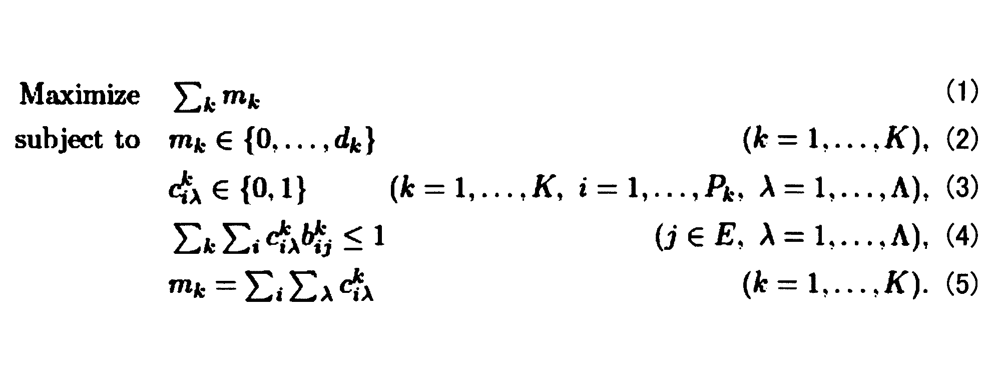
式(1)により各始点終点ペア(sk,tk)で割り当てられた光パスの本数の合計を最大化するのが光波長割当問題の目的となる。式(2)は、始点終点ペア(sk,tk)に割り当てる光パスの本数を需要の本数dkにまで抑える制約である。また、式(3)は、変数ciλ
kは経路pi
kで波長λの光パスを使う(ciλ
k=1)か、使わない(ciλ
k=0)かの2値しか取らないという制約を表している。
式(4)が重要な制約であり、波長λの光パスはリンクjを1回しか使えないという制約である。ここで、bij
kは経路pi
kがリンクjを使っている(bij
k=1)か、使っていない(bij
k=0)かを表す定数である。最後に、式(5)は、変数mkとciλ
kの関係を表す制約である。
なお、上記の数2に示す定式化は線形整数計画(ILP:Integer Linear Programming)による定式化であり、これ以外にも様々な定式化が考えられる。一般に1つの始点終点ペア(sk,tk)に対してその間の経路はグラフの大きさに対して指数的に多く存在し得るため、上記の数2に示す定式化も指数的に多くの変数を含む整数計画問題になっている。このため、上記の数2に示す定式化をそのまま市販の整数計画ソルバーに入力し解かせることは困難である。
これに対して、上述したように、ヒューリスティクスを用いて光波長割当問題を解く手法(例えば、非特許文献1や非特許文献2等)、列生成やBranch-and-priceと呼ばれる枠組みを用いて光波長割当問題を解く手法(例えば、非特許文献3等)が知られている。また、始点終点ペア間で考慮する経路の本数を制限したり、光波長割当問題に対して別の定式化を与えたりすることで、より簡単な整数計画問題に変換した上で整数計画ソルバーによって解く等といった手法も知られている。しかしながら、上述したように、これらの従来手法はいずれも、近似精度について保証がなかったり、現実に現れる細かな制約を取り入れるのが難しかったりするという課題がある。
<課題を解決するためのアプローチ>
そこで、本実施形態では、以下により上記の2つの課題を解決する。
そこで、本実施形態では、以下により上記の2つの課題を解決する。
近似精度の保証については、劣モジュラ関数最大化問題に対する貪欲法を援用したアプローチを行う。このアプローチにより、本実施形態に係る解算出装置10によって算出された解で割り当てられる光パスの本数は、最適解で割り当てられる光パスの本数に対して1-1/e≒0.632倍よりも悪くなることはないことが保証される。また、このアプローチは、実用的には最適解にかなり近い解を求められることが知られている。
なお、光波長割当問題の文脈における「劣モジュラ関数最大化問題に対する貪欲法」とは、以下のようなアルゴリズムのことをいう。
(a)1つの波長λ∈{1,・・・,Λ}のみに着目して、まだ需要を満たしていない始点終点ペアの中で、リンクを被らせずに経路を張れる最大本数を求める。
(b)上記の(a)を全ての波長λに対して繰り返す。
上記の(a)で、ある波長のみに着目して最大の本数を求めているのが貪欲法と呼ばれる所以である。
また、現実に現れる細かな制約を取り入れるために、上記のアプローチに対して二分決定グラフ(BDD:Binary Decision Diagram)とゼロサプレス型二分決定グラフ(ZDD:Zero-suppressed Binary Decision Diagram)とを組み合わせる。なお、BDDについては、参考文献2「Randal E. Bryant. Graph-based algorithms for Boolean function manipulation. IEEE Transactions on Computers, Vol. C-35, pp. 677-691, 1986.」を参照されたい。また、ZDDについては、参考文献3「Shin-ichi Minato. Zero-suppressed BDDs for set manipulation in combinatorial problems. In Proceedings of 30th ACM/IEEE Design Automation Conference, pp. 272-277, 1993.」を参照されたい。
BDDやZDDは、複数の経路の集合のような「組合せ集合」をコンパクトに表現できるデータ構造である。各始点終点ペア(sk,tk)に対してその間の経路のうち細かな制約を満たすもの全てをZDDとして保持することにより、実際の経路の本数に比べてコンパクトにこれらの各経路を保持することができる。
ここで、グラフGと始点終点ペア(sk,tk)とが与えられたとき、(sk,tk)間の経路の集合を表すZDDは、フロンティア法と呼ばれる手法により効率的に構築することができる。また、そのZDDに対して細かな制約を加えていくのも、上記の参考文献2や参考文献3に記載されているApply演算を用いることで容易に実現することができる。例えば、ホップ数をH以下に抑えるという制約は、要素数がH以下の組合せのみを集めた集合を表すZDDと、経路の集合を表すZDDとの共通部分を取るApply演算を行うことで実現することができる。
そこで、本実施形態では、始点終点ペア(sk,tk)の代わりに、その始点終点ペア(sk,tk)間の経路で所望の制約を満たすものの集合を表すZDD Zk(k=1,・・・,K)が解算出装置10に与えられるものとする。
<BDD及びZDD>
本実施形態の具体的な説明に入る前に、その準備としてBDD及びZDDの構造について説明する。
本実施形態の具体的な説明に入る前に、その準備としてBDD及びZDDの構造について説明する。
BDD及びZDDは、ノードと向きのあるエッジとの集まりでできたループのない有向非巡回グラフ(DAG:Directed acyclic graph)で組合せ集合を表現するデータ構造である。BDDとZDDは構造としては同一であるため、以下、まとめて説明する。
BDD(及びZDD)は、終端ノード
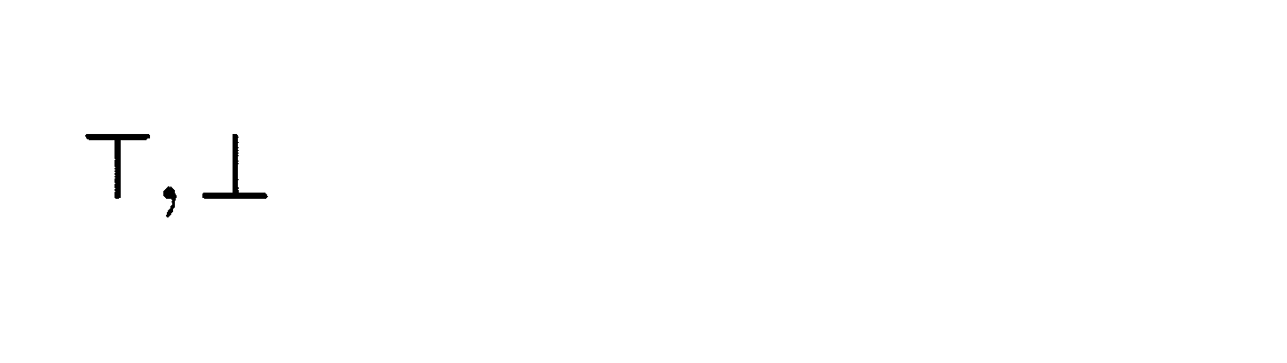
分岐ノードvに対して、この分岐ノードvから出る0-枝が指す先のノードを0-子ノードといい、lo(v)で表すものとする。同様に、分岐ノードvから出る1-枝が指す先のノードを1-子ノードといい、hi(v)で表すものとする。
また、各分岐ノードvにはラベルと呼ばれる整数値label(v)∈{1,・・・,c}が付与されており、これがアイテムの番号と対応している。アイテムとは、組合せ集合のもととなる集合(この例の場合、例えば、{a1,・・・,ac}といった集合)の要素のことである。なお、第1終端ノード及び第2終端ノードについては、ラベルの値をc+1と定義しておく。
このとき、各0-枝と1-枝は必ずラベルが小さい方のノードから大きい方のノードに向かうようにする。すなわち、任意の分岐ノードvに対して、label(v)<label(lo(v))、かつ、label(v)<label(hi(v))を満たすようにする。
BDD(及びZDD)は、分岐ノードから出る0-枝や1-枝の指す先が再びBDD(又はZDD)のノード(分岐ノード又は終端ノード)になっているという再帰的な構造を有している。このため、あるBDDノードvのことを「BDD v」ということもある。このBDD vは、BDDノードvと、このBDDノードvから辿れるすべてのBDDノードとを含んだ構造のBDDを意味する。一方で、あるBDD Vに対して、そのBDDの一番上のBDDノード(つまり、そのBDDで最もラベルの値が小さいノード)のことを「ノードV」又は「BDDノードV」ということもある。すなわち、BDDノードと、このBDDノードを一番上のノードとするBDDとは同一視することができる。ZDDについても同様である。なお、BDD及びZDDで一番上のノードはただ1つである。
なお、BDDとZDDの違いは表現している組合せ集合にあるが、これについては上記の参考文献2や参考文献3を参照されたい。
<ハードウェア構成>
次に、本実施形態に係る解算出装置10のハードウェア構成について、図1を参照しながら説明する。図1は、本実施形態に係る解算出装置10のハードウェア構成の一例を示す図である。
次に、本実施形態に係る解算出装置10のハードウェア構成について、図1を参照しながら説明する。図1は、本実施形態に係る解算出装置10のハードウェア構成の一例を示す図である。
図1に示すように、本実施形態に係る解算出装置10は一般的なコンピュータ又はコンピュータシステムのハードウェア構成で実現され、入力装置101と、表示装置102と、外部I/F103と、通信I/F104と、プロセッサ105と、メモリ装置106とを有する。これら各ハードウェアは、それぞれがバス107を介して通信可能に接続される。
入力装置101は、例えば、キーボードやマウス、タッチパネル等である。表示装置102は、例えば、ディスプレイ等である。なお、解算出装置10は、例えば、入力装置101及び表示装置102のうちの少なくとも一方を有していなくてもよい。
外部I/F103は、記録媒体103a等の外部装置とのインタフェースである。解算出装置10は、外部I/F103を介して、記録媒体103aの読み取りや書き込み等を行うことができる。なお、記録媒体103aとしては、例えば、CD(Compact Disc)、DVD(Digital Versatile Disk)、SDメモリカード(Secure Digital memory card)、USB(Universal Serial Bus)メモリカード等が挙げられる。
通信I/F104は、解算出装置10を通信ネットワークに接続するためのインタフェースである。プロセッサ105は、例えば、CPU(Central Processing Unit)やGPU(Graphics Processing Unit)等の各種演算装置である。メモリ装置106は、例えば、HDD(Hard Disk Drive)やSSD(Solid State Drive)、RAM(Random Access Memory)、ROM(Read Only Memory)、フラッシュメモリ等の各種記憶装置である。
本実施形態に係る解算出装置10は、図1に示すハードウェア構成を有することにより、後述する各種処理を実現することができる。なお、図1に示すハードウェア構成は一例であって、解算出装置10は、他のハードウェア構成を有していてもよい。例えば、解算出装置10は、複数のプロセッサ105を有していてもよいし、複数のメモリ装置106を有していてもよい。
<機能構成>
次に、本実施形態に係る解算出装置10の機能構成について、図2を参照しながら説明する。図2は、本実施形態に係る解算出装置10の機能構成の一例を示す図である。ここで、本実施形態に係る解算出装置10には、始点終点ペア(sk,tk)に対応するZDD Zk及び需要dk(k=1,・・・,K)と、WDM技術により使用できる波長数Λとが与えられる。上述したように、Zkは始点終点ペア(sk,tk)間の経路で所望の制約を満たすものの集合である。なお、各経路はリンク(光ファイバ)の組合せで表現される。
次に、本実施形態に係る解算出装置10の機能構成について、図2を参照しながら説明する。図2は、本実施形態に係る解算出装置10の機能構成の一例を示す図である。ここで、本実施形態に係る解算出装置10には、始点終点ペア(sk,tk)に対応するZDD Zk及び需要dk(k=1,・・・,K)と、WDM技術により使用できる波長数Λとが与えられる。上述したように、Zkは始点終点ペア(sk,tk)間の経路で所望の制約を満たすものの集合である。なお、各経路はリンク(光ファイバ)の組合せで表現される。
図2に示すように、本実施形態に係る解算出装置10は、入力部201と、前処理部202と、最適化部203と、出力部204とを有する。これら各機能部は、例えば、解算出装置10にインストールされた1以上のプログラムがプロセッサ105に実行させる処理により実現される。
入力部201は、与えられたZDD Zk及び需要dk(k=1,・・・,K)と波長数Λとを入力する。
前処理部202は、入力部201によって入力されたZkを用いて、1つの波長λだけを用いるときに光パスを詰め込む方法を列挙する。より正確には、前処理部202は、入力部201によって入力されたZkを用いて、複数の始点終点ペアを選んだときにそれらの始点終点ペア間でリンクが被らないように経路を張れるかどうかを網羅的に調べる。そして、前処理部202は、リンクが被らないように経路を張れる始点終点ペアの組合せの集合を表すBDD Rを出力する。
最適化部203は、前処理部202から出力されたRと、入力部201によって入力されたZDD Zk、需要dk及び波長数Λとを用いて、劣モジュラ関数最大化問題に対する貪欲法により光パスの割り当て方を求める。
出力部204は、最適化部203によって求めた光パスの割り当て方を出力する。なお、出力部204の出力先は特に限定されず、任意の出力先としてよい。このような出力先としては、例えば、ディスプレイや補助記憶装置、通信ネットワークを介して接続される他の機器又は装置等が挙げられる。
<光波長割当問題の解を算出する処理の流れ>
次に、本実施形態に係る解算出装置10によって光波長割当問題の解(近似解)を算出する処理の流れについて、図3を参照しながら説明する。図3は、光波長割当問題の解を算出する処理の流れの一例を示すフローチャートである。
次に、本実施形態に係る解算出装置10によって光波長割当問題の解(近似解)を算出する処理の流れについて、図3を参照しながら説明する。図3は、光波長割当問題の解を算出する処理の流れの一例を示すフローチャートである。
まず、入力部201は、与えられたZDD Zk及び需要dk(k=1,・・・,K)と波長数Λとを入力する(ステップS101)。
次に、前処理部202は、上記のステップS101で入力されたZkを用いて、リンクが被らないように経路を張れる始点終点ペアの組合せの集合を表すBDD Rを求める(ステップS102)。なお、本ステップの処理の詳細については後述する。
次に、最適化部203は、上記のステップS102で求めたBDD Rと、上記のステップS101で入力されたZDD Zk、需要dk及び波長数Λとを用いて、劣モジュラ関数最大化問題に対する貪欲法により光パスの割り当て方を求める(ステップS103)。なお、本ステップの処理の詳細については後述する。
そして、出力部204は、上記のステップS103で求めた光パスの割り当て方を出力する(ステップS104)。
以上により、本実施形態に係る解算出装置10は、光波長割当問題の解(光パスの割り当て方)を得ることができる。しかも、この解は、最適解に対して1-1/e≒0.632倍よりも悪くなることはないことが保証される。なお、本実施形態が採用する貪欲法のアプローチは、実用的には、最適解にかなり近い解が求められることが知られている。
また、本実施形態に係る解算出装置10は、BDD及びZDDというデータ構造を組み入れることにより、現実に現れる細かな制約も取り入れて光波長割当問題を解くことができる。
≪リンクが被らないように張れる始点終点ペアの組合せを求める処理≫
次に、上記のステップS102の処理の詳細について、図4を参照しながら説明する。図4は、リンクが被らないように経路を張れる始点終点ペアの組み合わせを求める処理の流れの一例を示すフローチャートである。ただし、以下では説明を簡単にするため1つの波長で同じ始点終点ペア間に2本以上の光パスを割り当てることはないものとする。なお、1つの波長で同じ始点終点ペア間に2本以上の光パスを割り当ててもよい場合には、始点終点ペア(sk,tk)に対応するZDD Zkを複数個入力することで実現可能である。
次に、上記のステップS102の処理の詳細について、図4を参照しながら説明する。図4は、リンクが被らないように経路を張れる始点終点ペアの組み合わせを求める処理の流れの一例を示すフローチャートである。ただし、以下では説明を簡単にするため1つの波長で同じ始点終点ペア間に2本以上の光パスを割り当てることはないものとする。なお、1つの波長で同じ始点終点ペア間に2本以上の光パスを割り当ててもよい場合には、始点終点ペア(sk,tk)に対応するZDD Zkを複数個入力することで実現可能である。
前処理部202は、R←⊥とする(ステップS201)。すなわち、前処理部202は、リンクが被らないように経路を張れる始点終点ペアの組合せの集合を表すBDD Rを、組合せを1つも含まない集合{}に初期化する。なお、⊥は組合せを1つも含まない集合{}を表すBDDを意味する。
次に、前処理部202は、各d=1,・・・,Kに対してTd←⊥(ステップS202)。すなわち、前処理部202は、BDDノードを表す変数Tdを第2終端ノードに初期化する。
次に、前処理部202は、
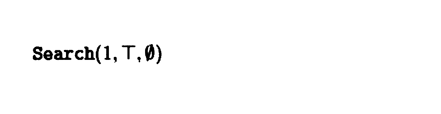
そして、前処理部202は、上記のステップS203におけるSearch手続きで更新されたBDD Rを出力する(ステップS204)。このBDD Rが、リンクが被らないように経路を張れる始点終点ペアの組合せの集合である。
・Search(d,Z,S)
ここで、Search(d,Z,S)の詳細について、図5を参照しながら説明する。図5は、Search(d,Z,S)の一例を示す図である。このSearch手続きは深さ優先探索に基づいており、Sは現在経路を張っている始点終点ペアの番号の集合を表し、dは現在注目している始点終点ペアの番号を表す。このとき、Search手続きでは、集合Sにdを追加するかしないか、すなわちd番目の始点終点ペアに経路を張るか張らないかで探索を分岐させる。また、探索中に同じリンクを使わずに経路を張ることができなくなったら、その時点で探索を打ち切る。一方で、最後の始点終点ペアを処理した時点で経路を張れたならば、Sのべき集合をRに加える。この「経路を張ることができるかできないか」という部分の判定にZDD ZとZDD同士のDisjointJoin演算と呼ばれる演算とを用いる。
ここで、Search(d,Z,S)の詳細について、図5を参照しながら説明する。図5は、Search(d,Z,S)の一例を示す図である。このSearch手続きは深さ優先探索に基づいており、Sは現在経路を張っている始点終点ペアの番号の集合を表し、dは現在注目している始点終点ペアの番号を表す。このとき、Search手続きでは、集合Sにdを追加するかしないか、すなわちd番目の始点終点ペアに経路を張るか張らないかで探索を分岐させる。また、探索中に同じリンクを使わずに経路を張ることができなくなったら、その時点で探索を打ち切る。一方で、最後の始点終点ペアを処理した時点で経路を張れたならば、Sのべき集合をRに加える。この「経路を張ることができるかできないか」という部分の判定にZDD ZとZDD同士のDisjointJoin演算と呼ばれる演算とを用いる。
まず、前処理部202は、Zが第2終端ノードであれば、何もせずにSearch手続きを終了する(2~3行目)。
次に、前処理部202は、d>Kが成り立つならば、まずApply演算により、Rが表す組合せ集合とSのべき集合との和を演算し、この和でRを更新する(4~5行目)。続いて、前処理部202は、UpdateTrack手続きを呼び出し、Search手続きを終了する(6~7行目)。ここで、Powerset(S)はSのべき集合を表すBDDノードを出力するサブルーチンである。また、UpdateTrack手続きはSを引数として取るサブルーチンであり、BDDノードを表す変数Tdを更新する。なお、Powerset(S)についてはその実現が容易であるため省略する。一方で、UpdateTrack(S)の詳細については後述する。
上記の2行目の条件と4行目の条件とが成り立たない場合、前処理部202は、8行目以降の処理を行う。まず、前処理部202は、BDDノードTdのラベルがdならば、Td+1にhi(Td)を代入し(8行目)、そうでなければTd+1にTdを代入し(9行目)、Search手続きを再帰的に呼び出す(10行目)。この8~10行目の処理は、d番目の始点終点ペアに経路を張る場合の探索に対応する。ここで、10行目で呼び出すSearch手続きの第1引数にはd+1、第2引数にはZとZdとのDisjointJoin演算の結果、第3引数にはSと{d}の和をそれぞれ指定する。このとき、ZとZdとのDisjointJoin演算の結果を第2引数に指定することで、「同じリンクを使わずに経路を張ることができるかどうか」の探索が実現される。なお、ZDDにおけるDisjointJoin演算の詳細については、例えば、参考文献4「Jun Kawahara, Toshiki Saitoh, Hirofumi Suzuki, and Ryo Yoshinaka. Solving the longest one-way ticket problem and enumerating letter graphs by augmenting the two representative approaches with ZDDs. In Proceedings of Computational Intelligence in Information Systems Conference, pp. 294-305, 2016.」等を参照されたい。
続く11行目~15行目の処理はd番目の始点終点ペアに経路を張らない場合の探索に対応する。まず、前処理部202は、BDDノードTdのラベルがdならば、Td+1にlo(Td)を代入し(11行目)、そうでなければTd+1にTdを代入する(12行目)。次に、前処理部202は、Td+1が第1終端ノードであればこれ以上の探索は行わずにSearch手続きを終了する(13行目~14行目)。Td+1が第1終端ノードであるという条件は、d+1番目以降のどの始点終点ペアにもリンクを被らせることなく経路を張れる、という意味になるため、この場合はこれ以上の探索を行う必要はないためである。
一方で、前処理部202は、Td+1が第1終端ノードでなければ、Search手続きを再帰的に呼び出す(15行目)。ここで、15行目で呼び出すSearch手続きの第1引数にはd+1、第2引数にはZ、第3引数にはSをそれぞれ指定する。
・UpdateTrack(S)
次に、UpdateTrack(S)の詳細について、図6を参照しながら説明する。図6は、UpdateTrack(S)の一例を示す図である。このUpdateTrack手続きは、BDDノードを表す変数Tdを更新する手続きである。なお、Sは、{1,・・・,K}の部分集合である。
次に、UpdateTrack(S)の詳細について、図6を参照しながら説明する。図6は、UpdateTrack(S)の一例を示す図である。このUpdateTrack手続きは、BDDノードを表す変数Tdを更新する手続きである。なお、Sは、{1,・・・,K}の部分集合である。
まず、前処理部202は、T1にRを代入する(2行目)。なお、上述したように、Rは、BDD Rの一番上のノードを指す。
次に、前処理部202は、各d=1,・・・,Kに対して以下の処理を繰り返し実行する(3行目)。すなわち、前処理部202は、Tdのラベルがdならば(4行目)、d∈SのときTd+1にhi(Td)を代入し(5行目)、d∈SでないときTd+1にlo(Td)を代入(6行目)する。一方で、前処理部202は、Tdのラベルがdでないならば、Td+1にTdを代入する(7行目)。
≪貪欲法により光パスの割り当て方を求める処理≫
次に、上記のステップS103の処理の詳細について、図7を参照しながら説明する。図7は、貪欲法により光パスの割り当て方を求める処理の流れの一例を示すフローチャートである。この処理は劣モジュラ関数最大化問題に対する貪欲法に基づくものであり、未だ需要が満たされていない始点終点ペアの中でリンクを被らせずに経路を張れる最大の部分集合をR上の動的計画法により求めた上で、その部分集合に含まれる各始点終点ペア間の経路に対して波長λを割り当てる、ということを1波長ずつ逐次的に繰り返していくものである。
次に、上記のステップS103の処理の詳細について、図7を参照しながら説明する。図7は、貪欲法により光パスの割り当て方を求める処理の流れの一例を示すフローチャートである。この処理は劣モジュラ関数最大化問題に対する貪欲法に基づくものであり、未だ需要が満たされていない始点終点ペアの中でリンクを被らせずに経路を張れる最大の部分集合をR上の動的計画法により求めた上で、その部分集合に含まれる各始点終点ペア間の経路に対して波長λを割り当てる、ということを1波長ずつ逐次的に繰り返していくものである。
最適化部203は、各λ=1,・・・,Λに対して、ステップS310~ステップS340の処理を繰り返す(ステップS300)。
ステップS310では、最適化部203は、各k=1,・・・,Kに対して、ステップS311の処理と、ステップS312又はステップS313の処理とを繰り返す(ステップS310)。すなわち、最適化部203は、まずk番目の始点終点ペアの需要dkが未だ満たされていないかを判定し(ステップS311)、満たされていなければ重みwkに1を設定し(ステップS312)、満たされていれば重みwkに0を設定する(ステップS313)。
ステップS320では、最適化部203は、重みwk(k=1,・・・,K)を用いて、以下の参考文献5に記載されているAlgorithm Bを実行し、始点終点ペアの集合Sを得る。このAlgorithm Bは、R上の動的計画法に基づいて、BDD Rに含まれる組合せ(つまり、始点終点ペアの組合せ)の中で重みの和が最大となるような組合せを求める手続きである。これにより、未だ需要が満たされていない始点終点ペアの中でリンクを被らせずに経路を張ることができ、かつ、最大の始点終点ペア数を持つ集合がSとして得られる。
参考文献5「Donald E. Knuth. The Art of Computer Programming, Volume 4 Fascicle 1: Bitwise Tricks & Techniques; Binary Decision Diagrams. Addison-Wesley Educational Publishers Inc., Verlag, pp. 0-10, 2009. ISBN: 978-0-321-58050-4.」
次に、ステップS330では、最適化部203は、上記のステップS320で得られた始点終点ペア集合Sに含まれる各始点集合ペア間の経路(ただし、他の経路とリンクが被らない経路)の集合Qを、GetDisjointCombs手続きにより得る。ここで、GetDisjointCombs手続きは、上記の始点終点ペア集合Sと、ZDD Z1,・・・,ZKとを引数として取るサブルーチンである。GetDisjointCombs(S,Z1,・・・,ZK)の詳細については後述する。
次に、ステップS330では、最適化部203は、上記のステップS320で得られた始点終点ペア集合Sに含まれる各始点集合ペア間の経路(ただし、他の経路とリンクが被らない経路)の集合Qを、GetDisjointCombs手続きにより得る。ここで、GetDisjointCombs手続きは、上記の始点終点ペア集合Sと、ZDD Z1,・・・,ZKとを引数として取るサブルーチンである。GetDisjointCombs(S,Z1,・・・,ZK)の詳細については後述する。
そして、ステップS340では、最適化部203は、上記のステップS330で得られた経路集合Qに含まれる各経路に対して波長λを割り当てる。これにより、波長λの光パスの集合が得られる。すなわち、波長λの繰り返しのときに得られた経路集合Qに対して、当該波長λを割り当てた光パス集合をQλとすれば、{Qλ|λ=1,・・・,Λ}が光波長割当問題の解であり、光パスの割り当て方を表す。
・GetDisjointCombs(S,Z1,・・・,ZK)
次に、GetDisjointCombs(S,Z1,・・・,ZK)の詳細について、図8を参照しながら説明する。図8は、GetDisjointCombs(S,Z1,・・・,ZK)の一例を示す図である。このGetDisjointCombs手続きは、始点終点ペア集合Sに含まれる各始点集合ペアで、実際にリンクが被らない経路の集合Qを求める手続きである。
次に、GetDisjointCombs(S,Z1,・・・,ZK)の詳細について、図8を参照しながら説明する。図8は、GetDisjointCombs(S,Z1,・・・,ZK)の一例を示す図である。このGetDisjointCombs手続きは、始点終点ペア集合Sに含まれる各始点集合ペアで、実際にリンクが被らない経路の集合Qを求める手続きである。
ここで、以下では説明を簡単にするため、始点集合ペア集合Sは始点集合ペアの番号を要素とする集合で与えられるものとする。例えば、(s3,t3),(s5,t5),(s6,t6)という3つの始点終点ペアの集合は、{3,5,6}という集合で与えられるものとする。
まず、最適化部203は、Y0を第1終端ノードに初期化する(2行目)と共に、iを0に初期化する(3行目)。ここで、iは0以上の整数を表す変数、YiはZDDノードを表す変数である。
次に、最適化部203は、各k∈Sに対して5行目~6行目の繰り返し実行する(4行目)。5行目~6行目では、最適化部203は、iに1を加算した上で、Yi-1とZkとのDisjointJoin演算の結果をYiに代入する。これにより、元のグラフGに対してその「辺(リンク)の組合せ」を表現するZDD Yiが得られる。
次に、最適化部203は、Yiの中から任意の組合せを選び、Cに代入する(7行目)。
続いて、最適化部203は、4行目でkを選んだときの逆順でk∈Sを選び、各kに対して9行目~10行目を繰り返し実行する(8行目)。9行目~10行目では、最適化部203は、Decompose手続きにより(r,C,Pk)を求めた後、iから1を減じる。ここで、Decompose手続きはZDD FとZDD Gと組合せ集合Cとを引数として取るサブルーチンであり、経路Pkを求めて(r,C,Pk)を出力する。Decompose(Yi-1,Zk,C)の詳細については後述する。なお、rはtrue又はfalseの2値を取る変数である。
そして、最適化部203は、経路集合Q={Pk|k∈S}を出力する(11行目)。
・Decompose(F,G,C)
次に、Decompose(F,G,C)の詳細について、図9を参照しながら説明する。図9は、Decompose(F,G,C)の一例を示す図である。このDecompose手続きは、2つのZDD F,Gが与えられたときに、Fに含まれる組合せCFとGに含まれる組合せCGであって、CF∪CG=CかつCF∩CG=φであるような組合せCF及びCGか、もしこのような組合せCF及びCGが見つからなければその旨を出力する手続きである。r=trueは上記のような組合せCF及びCGが見つかったことを表し、r=falseは見つからなかったことを表す。なお、Decompose手続きの第2引数を表す記号にGを用いているが、光ネットワークを表す有向グラフGを指すものではないため留意されたい。
次に、Decompose(F,G,C)の詳細について、図9を参照しながら説明する。図9は、Decompose(F,G,C)の一例を示す図である。このDecompose手続きは、2つのZDD F,Gが与えられたときに、Fに含まれる組合せCFとGに含まれる組合せCGであって、CF∪CG=CかつCF∩CG=φであるような組合せCF及びCGか、もしこのような組合せCF及びCGが見つからなければその旨を出力する手続きである。r=trueは上記のような組合せCF及びCGが見つかったことを表し、r=falseは見つからなかったことを表す。なお、Decompose手続きの第2引数を表す記号にGを用いているが、光ネットワークを表す有向グラフGを指すものではないため留意されたい。
ここで、上述したように、BDDやZDDはアイテムの組合せ集合を表現するデータ構造であり、アイテムに番号を付けることでノードのラベルの値と対応させている。そこで、以下では簡単のため組合せCはアイテムの番号のリストである(又は、このようなリストを保持している)とする。例えば、Cが{a3,a5,a6}といった組合せを表す場合、C={3,5,6}であるものとする。
まず、2行目~5行目では探索を行わなくても解を出力できる場合を扱う。すなわち、2行目では、最適化部203は、Fのラベルの値より小さく、かつ、Gのラベルの値よりも小さい番号がCにあれば、組合せCF及びCGは見つからない旨(false,φ,φ)を出力する。なお、上述したように、label(F)はZDD Fの一番上のノードのラベルの値である。label(G)についても同様である。
3行目では、最適化部203は、FとGが共に第1終端ノードである場合、(true,φ,φ)を出力する。この場合、CF=CG=φである。
4行目では、最適化部203は、F又はGのいずれかが第2終端ノードである場合、見つからない旨(false,φ,φ)を出力する。
5行目では、最適化部203は、FとGの組が失敗ペア集合Xに入っていた場合、見つからない旨(false,φ,φ)を出力する。ここで、失敗ペア集合Xは該当する組合せが見つからないケースを保持しておくキャッシュであり、予めX=φと初期化されている。
次に、6行目以降は探索を行わないと解を出力でない場合を扱う。最適化部203は、Fのラベルの値がGのラベルよりも値よりも小さい場合(6行目)に、Fのラベルの値がCの中にあれば(7行目)、Decompose手続きを再帰的に呼び出す(8行目)。このとき、Decompose手続きの第1引数にはhi(F)、第2引数にはG、第3引数にはC\{label(F)}をそれぞれ指定する。そして、最適化部203は、この8行目で呼び出されたDecompose手続きの結果(r,CF,CG)のうちrがtrueである場合(つまり、該当の組合せCF及びCGが見つかった場合)、CFに対してFのラベルの値を追加する(9行目)。
一方で、最適化部203は、Fのラベルの値がGのラベルよりも値よりも小さい場合に、Fのラベルの値がCの中に無ければ(10行目)、Decompose手続きを再帰的に呼び出す(11行目)。このとき、Decompose手続きの第1引数にはlo(F)、第2引数にはG、第3引数にはCをそれぞれ指定する。
続く12行目~17行目はGのラベルの値がFのラベルの値よりも小さい場合の処理である。この12行目~17行目の処理は、6行目~11行目の処理でFとGを入れ替えたものであるため、その説明を省略する。
続く18行目~26行目はFのラベルの値とGのラベルの値とが同じ場合の処理である。最適化部203は、Fのラベルの値がCの中にあれば(19行目)、Decompose手続きを再帰的に呼び出す(20行目)。このとき、Decompose手続きの第1引数にはhi(F)、第2引数にはlo(G)、第3引数にはC\{label(F)}をそれぞれ指定する。そして、最適化部203は、この20行目で呼び出されたDecompose手続きの結果(r,CF,CG)のうちrがtrueである場合、CFに対してFのラベルの値を追加する(21行目)。
これに対して、最適化部203は、20行目で呼び出されたDecompose手続きの結果(r,CF,CG)のうちrがfalseである場合(つまり、該当の組合せCF及びCGが見つからなかった場合)、別の引数でDecompose手続きを再帰的に呼び出す(23行目)。このとき、Decompose手続きの第1引数にはlo(F)、第2引数にはhi(G)、第3引数にはC\{label(G)}をそれぞれ指定する。そして、最適化部203は、この23行目で呼び出されたDecompose手続きの結果(r,CF,CG)のうちrがtrueである場合、CGに対してGのラベルの値を追加する(24行目)。
一方で、最適化部203は、Fのラベルの値とGのラベルの値とが同じ場合に、Fのラベルの値がCの中に無ければ(25行目)、Decompose手続きを再帰的に呼び出す(26行目)。このとき、Decompose手続きの第1引数にはlo(F)、第2引数にはlo(G)、第3引数にはCをそれぞれ指定する。
以上の6行目~26行目までの探索の結果、該当する組合せCF及びCGが見つからなければ、最適化部203は、失敗ペア集合Xに(F,G)を追加する(27行目)。
最後に、最適化部203は、(r,CF,CG)を出力する(28行目)。
本発明は、具体的に開示された上記の実施形態に限定されるものではなく、請求の範囲の記載から逸脱することなく、種々の変形や変更、既知の技術との組み合わせ等が可能である。
10 解算出装置
101 入力装置
102 表示装置
103 外部I/F
103a 記録媒体
104 通信I/F
105 プロセッサ
106 メモリ装置
107 バス
201 入力部
202 前処理部
203 最適化部
204 出力部
101 入力装置
102 表示装置
103 外部I/F
103a 記録媒体
104 通信I/F
105 プロセッサ
106 メモリ装置
107 バス
201 入力部
202 前処理部
203 最適化部
204 出力部
Claims (6)
- 光ネットワーク上の光波長割当問題の解を算出する解算出方法であって、
前記光ネットワークの始点sk及び終点tk間で所定の制約を満たす経路の集合を表すゼロサプレス型二分決定グラフZk(ただし、k=1,・・・,K)と、前記ゼロサプレス型二分決定グラフZkに対応する需要dkと、前記光ネットワークで使用可能な波長の数Λとを入力する入力手順と、
前記ゼロサプレス型二分決定グラフZkを用いて、前記経路を構成するリンクが被らない前記始点sk及び前記終点tkのペアの組合せの集合を表す二分決定グラフRを算出する前処理手順と、
前記ゼロサプレス型二分決定グラフZkと、前記需要dkと、前記二分決定グラフRと、前記波長の数Λとを用いて、劣モジュラ関数最大化問題に対する貪欲法により、前記始点sk及び前記終点tk間における経路と該経路で使用する波長とを表す光パスを算出する最適化手順と、
前記始点sk及び前記終点tkにおける光パスを、前記光波長割当問題の解として出力する出力手順と、
をコンピュータが実行することを特徴とする解算出方法。 - 前記需要dkは、前記始点sk及び前記終点tk間に割り当てる光パスの本数であり、
前記最適化手順は、
前記波長ごとに、未だ前記需要dkが満たされていない前記始点sk及び前記終点tkのペアを要素とする集合のうち、前記経路を構成するリンクが被らないペアを要素とする最大の部分集合SをR上の動的計画法により算出した上で、前記部分集合Sと前記ゼロサプレス型二分決定グラフZkとを用いて、前記部分集合Sに含まれるペアが表す始点sk及び終点tk間における経路を算出し、算出した経路を、前記波長を使用する光パスとする、ことを特徴とする請求項1に記載の解算出方法。 - 前記制約は、前記経路のホップ数が所定の数H以下であることであり、
前記入力手順は、
前記始点sk及び前記終点tk間の経路の組合せの集合を表すゼロサプレス型二分決定グラフとH以下の要素数の組合せの集合を表すゼロサプレス型二分決定グラフとのApply演算結果を前記ゼロサプレス型二分決定グラフZkとして入力する、ことを特徴とする請求項1又は2に記載の解算出方法。 - 前記前処理手順は、
前記始点sk及び前記終点tkのペアごとに、深さ優先探索に基づいて、他の始点sk及び終点tk間の経路を構成するリンクを使用しないで経路を張れるか否かを探索することで、前記二分決定グラフRを算出する、ことを特徴とする請求項1乃至3の何れか一項に記載の解算出方法。 - 光ネットワーク上の光波長割当問題の解を算出する解算出装置であって、
前記光ネットワークの始点sk及び終点tk間で所定の制約を満たす経路の集合を表すゼロサプレス型二分決定グラフZk(ただし、k=1,・・・,K)と、前記ゼロサプレス型二分決定グラフZkに対応する需要dkと、前記光ネットワークで使用可能な波長の数Λとを入力する入力部と、
前記ゼロサプレス型二分決定グラフZkを用いて、前記経路を構成するリンクが被らない前記始点sk及び前記終点tkのペアの組合せの集合を表す二分決定グラフRを算出する前処理部と、
前記ゼロサプレス型二分決定グラフZkと、前記需要dkと、前記二分決定グラフRと、前記波長の数Λとを用いて、劣モジュラ関数最大化問題に対する貪欲法により、前記始点sk及び前記終点tk間における経路と該経路で使用する波長とを表す光パスを算出する最適化部と、
前記始点sk及び前記終点tkにおける光パスを、前記光波長割当問題の解として出力する出力部と、
を有することを特徴とする解算出装置。 - コンピュータに、請求項1乃至4の何れか一項に記載の解算出方法を実行させるプログラム。
Priority Applications (2)
| Application Number | Priority Date | Filing Date | Title |
|---|---|---|---|
| PCT/JP2020/046147 WO2022123749A1 (ja) | 2020-12-10 | 2020-12-10 | 解算出方法、解算出装置及びプログラム |
| JP2022567990A JP7501666B2 (ja) | 2020-12-10 | 2020-12-10 | 解算出方法、解算出装置及びプログラム |
Applications Claiming Priority (1)
| Application Number | Priority Date | Filing Date | Title |
|---|---|---|---|
| PCT/JP2020/046147 WO2022123749A1 (ja) | 2020-12-10 | 2020-12-10 | 解算出方法、解算出装置及びプログラム |
Publications (1)
| Publication Number | Publication Date |
|---|---|
| WO2022123749A1 true WO2022123749A1 (ja) | 2022-06-16 |
Family
ID=81973480
Family Applications (1)
| Application Number | Title | Priority Date | Filing Date |
|---|---|---|---|
| PCT/JP2020/046147 Ceased WO2022123749A1 (ja) | 2020-12-10 | 2020-12-10 | 解算出方法、解算出装置及びプログラム |
Country Status (2)
| Country | Link |
|---|---|
| JP (1) | JP7501666B2 (ja) |
| WO (1) | WO2022123749A1 (ja) |
Cited By (2)
| Publication number | Priority date | Publication date | Assignee | Title |
|---|---|---|---|---|
| WO2024232015A1 (ja) * | 2023-05-09 | 2024-11-14 | 日本電信電話株式会社 | 索引構築装置、索引構築方法及びプログラム |
| WO2024232014A1 (ja) * | 2023-05-09 | 2024-11-14 | 日本電信電話株式会社 | 最適値計算装置、最適値計算方法及びプログラム |
Citations (2)
| Publication number | Priority date | Publication date | Assignee | Title |
|---|---|---|---|---|
| JP2004336199A (ja) * | 2003-05-01 | 2004-11-25 | Nippon Telegr & Teleph Corp <Ntt> | 光パス設定装置及び方法 |
| JP2005522090A (ja) * | 2002-03-28 | 2005-07-21 | マティス ネットワークス | リザーブベースのmacおよび光学式ネットワーク |
Family Cites Families (4)
| Publication number | Priority date | Publication date | Assignee | Title |
|---|---|---|---|---|
| US7716271B1 (en) | 2001-06-05 | 2010-05-11 | Massachusetts Institute Of Technology | Routing and wavelength assignment in optical networks |
| US7171124B2 (en) | 2001-07-19 | 2007-01-30 | Lucent Technologies Inc. | Wavelength routing and switching mechanism for a photonic transport network |
| JP2005260729A (ja) | 2004-03-12 | 2005-09-22 | Nippon Telegr & Teleph Corp <Ntt> | 帯域保証型光vpnパス設計システムと方法およびプログラム |
| US9197350B2 (en) * | 2012-10-08 | 2015-11-24 | Fujitsu Limited | Systems and methods for routing and wavelength assignment for network virtualization |
-
2020
- 2020-12-10 JP JP2022567990A patent/JP7501666B2/ja active Active
- 2020-12-10 WO PCT/JP2020/046147 patent/WO2022123749A1/ja not_active Ceased
Patent Citations (2)
| Publication number | Priority date | Publication date | Assignee | Title |
|---|---|---|---|---|
| JP2005522090A (ja) * | 2002-03-28 | 2005-07-21 | マティス ネットワークス | リザーブベースのmacおよび光学式ネットワーク |
| JP2004336199A (ja) * | 2003-05-01 | 2004-11-25 | Nippon Telegr & Teleph Corp <Ntt> | 光パス設定装置及び方法 |
Non-Patent Citations (1)
| Title |
|---|
| SUZUKI, HIROFUMI ET AL.: "Solving Various Network Design Problems Using ZDDs", PROCEEDINGS OF THE ANNUAL CONFERENCE OF JSAI, 5 June 2018 (2018-06-05), pages 1 - 4 * |
Cited By (2)
| Publication number | Priority date | Publication date | Assignee | Title |
|---|---|---|---|---|
| WO2024232015A1 (ja) * | 2023-05-09 | 2024-11-14 | 日本電信電話株式会社 | 索引構築装置、索引構築方法及びプログラム |
| WO2024232014A1 (ja) * | 2023-05-09 | 2024-11-14 | 日本電信電話株式会社 | 最適値計算装置、最適値計算方法及びプログラム |
Also Published As
| Publication number | Publication date |
|---|---|
| JP7501666B2 (ja) | 2024-06-18 |
| JPWO2022123749A1 (ja) | 2022-06-16 |
Similar Documents
| Publication | Publication Date | Title |
|---|---|---|
| JP7501666B2 (ja) | 解算出方法、解算出装置及びプログラム | |
| Song et al. | A constructive particle swarm optimizer for virtual network embedding | |
| van Hoeve | Graph coloring lower bounds from decision diagrams | |
| Quek et al. | A depth-first search algorithm to compute elementary flux modes by linear programming | |
| JP2012146137A (ja) | 情報処理装置およびプログラム | |
| Jawahar et al. | Automoe: Heterogeneous mixture-of-experts with adaptive computation for efficient neural machine translation | |
| CN113837252A (zh) | 聚类处理方法和装置 | |
| Onsu et al. | Unlocking reconfigurability for deep reinforcement learning in sfc provisioning | |
| CN120075124B (zh) | 一种智能光纤配线机器集群的路由调度方法及装置 | |
| Taal et al. | Profiling the scheduling decisions for handling critical paths in deadline-constrained cloud workflows | |
| Kamath et al. | M5: Multi-modal multi-task model mapping on multi-FPGA with accelerator configuration search | |
| Nguyen et al. | On the feasibility of hybrid electrical/optical switch architecture for large-scale training of distributed deep learning | |
| Merino et al. | A specification language for performance and economical analysis of short term data intensive energy management services | |
| US20250036989A1 (en) | Efficient hamiltonian exponentiation in a quantum circuit | |
| Roche et al. | On constructing DAG‐schedules with large areas | |
| Zitkovich et al. | Event-Oriented Simulation Module for Dynamic Elastic Optical Networks with Space Division Multiplexing. | |
| Ostrowski | An approximation of betweenness centrality for social networks | |
| US11838186B2 (en) | Topology design apparatus, topology design method and program | |
| Wang et al. | Monte carlo tree search for task mapping onto heterogeneous platforms | |
| Ostrowski | MapReduce design patterns for social networking analysis | |
| Wu et al. | PORT: Efficient Training-Free Online Routing for High-Volume Multi-LLM Serving | |
| JP7687392B2 (ja) | 経路決定装置、経路決定方法、及びプログラム | |
| Tallent et al. | Modeling the impact of silicon photonics on graph analytics | |
| Kayal et al. | QoS-aware, cost-efficient scheduling for data-intensive DAGs in multi-tier computing environment | |
| Benoit et al. | On the complexity of mapping linear chain applications onto heterogeneous platforms |
Legal Events
| Date | Code | Title | Description |
|---|---|---|---|
| 121 | Ep: the epo has been informed by wipo that ep was designated in this application |
Ref document number: 20965131 Country of ref document: EP Kind code of ref document: A1 |
|
| ENP | Entry into the national phase |
Ref document number: 2022567990 Country of ref document: JP Kind code of ref document: A |
|
| NENP | Non-entry into the national phase |
Ref country code: DE |
|
| 122 | Ep: pct application non-entry in european phase |
Ref document number: 20965131 Country of ref document: EP Kind code of ref document: A1 |