WO2022118459A1 - Redundant system - Google Patents
Redundant system Download PDFInfo
- Publication number
- WO2022118459A1 WO2022118459A1 PCT/JP2020/045205 JP2020045205W WO2022118459A1 WO 2022118459 A1 WO2022118459 A1 WO 2022118459A1 JP 2020045205 W JP2020045205 W JP 2020045205W WO 2022118459 A1 WO2022118459 A1 WO 2022118459A1
- Authority
- WO
- WIPO (PCT)
- Prior art keywords
- power supply
- ecu
- vehicle
- supply system
- operation control
- Prior art date
Links
- 230000005856 abnormality Effects 0.000 claims abstract description 120
- 238000012545 processing Methods 0.000 claims abstract description 3
- 238000001514 detection method Methods 0.000 claims description 59
- 238000012544 monitoring process Methods 0.000 claims description 39
- 238000000034 method Methods 0.000 claims description 17
- 230000008569 process Effects 0.000 claims description 17
- 238000012806 monitoring device Methods 0.000 claims 5
- 230000006870 function Effects 0.000 description 34
- 230000014509 gene expression Effects 0.000 description 9
- HEZMWWAKWCSUCB-PHDIDXHHSA-N (3R,4R)-3,4-dihydroxycyclohexa-1,5-diene-1-carboxylic acid Chemical compound O[C@@H]1C=CC(C(O)=O)=C[C@H]1O HEZMWWAKWCSUCB-PHDIDXHHSA-N 0.000 description 8
- 238000010586 diagram Methods 0.000 description 8
- 238000013461 design Methods 0.000 description 5
- 230000000694 effects Effects 0.000 description 2
- 239000004065 semiconductor Substances 0.000 description 2
- HBBGRARXTFLTSG-UHFFFAOYSA-N Lithium ion Chemical compound [Li+] HBBGRARXTFLTSG-UHFFFAOYSA-N 0.000 description 1
- 230000001133 acceleration Effects 0.000 description 1
- 230000006399 behavior Effects 0.000 description 1
- 230000008859 change Effects 0.000 description 1
- 238000004891 communication Methods 0.000 description 1
- 230000036461 convulsion Effects 0.000 description 1
- 229910001416 lithium ion Inorganic materials 0.000 description 1
- 238000012423 maintenance Methods 0.000 description 1
- 230000007246 mechanism Effects 0.000 description 1
- 230000004044 response Effects 0.000 description 1
- 238000004092 self-diagnosis Methods 0.000 description 1
- 230000007480 spreading Effects 0.000 description 1
Images


Classifications
-
- B—PERFORMING OPERATIONS; TRANSPORTING
- B60—VEHICLES IN GENERAL
- B60W—CONJOINT CONTROL OF VEHICLE SUB-UNITS OF DIFFERENT TYPE OR DIFFERENT FUNCTION; CONTROL SYSTEMS SPECIALLY ADAPTED FOR HYBRID VEHICLES; ROAD VEHICLE DRIVE CONTROL SYSTEMS FOR PURPOSES NOT RELATED TO THE CONTROL OF A PARTICULAR SUB-UNIT
- B60W50/00—Details of control systems for road vehicle drive control not related to the control of a particular sub-unit, e.g. process diagnostic or vehicle driver interfaces
- B60W50/02—Ensuring safety in case of control system failures, e.g. by diagnosing, circumventing or fixing failures
- B60W50/023—Avoiding failures by using redundant parts
-
- B—PERFORMING OPERATIONS; TRANSPORTING
- B60—VEHICLES IN GENERAL
- B60W—CONJOINT CONTROL OF VEHICLE SUB-UNITS OF DIFFERENT TYPE OR DIFFERENT FUNCTION; CONTROL SYSTEMS SPECIALLY ADAPTED FOR HYBRID VEHICLES; ROAD VEHICLE DRIVE CONTROL SYSTEMS FOR PURPOSES NOT RELATED TO THE CONTROL OF A PARTICULAR SUB-UNIT
- B60W60/00—Drive control systems specially adapted for autonomous road vehicles
- B60W60/007—Emergency override
-
- B—PERFORMING OPERATIONS; TRANSPORTING
- B60—VEHICLES IN GENERAL
- B60W—CONJOINT CONTROL OF VEHICLE SUB-UNITS OF DIFFERENT TYPE OR DIFFERENT FUNCTION; CONTROL SYSTEMS SPECIALLY ADAPTED FOR HYBRID VEHICLES; ROAD VEHICLE DRIVE CONTROL SYSTEMS FOR PURPOSES NOT RELATED TO THE CONTROL OF A PARTICULAR SUB-UNIT
- B60W10/00—Conjoint control of vehicle sub-units of different type or different function
- B60W10/20—Conjoint control of vehicle sub-units of different type or different function including control of steering systems
-
- B—PERFORMING OPERATIONS; TRANSPORTING
- B60—VEHICLES IN GENERAL
- B60W—CONJOINT CONTROL OF VEHICLE SUB-UNITS OF DIFFERENT TYPE OR DIFFERENT FUNCTION; CONTROL SYSTEMS SPECIALLY ADAPTED FOR HYBRID VEHICLES; ROAD VEHICLE DRIVE CONTROL SYSTEMS FOR PURPOSES NOT RELATED TO THE CONTROL OF A PARTICULAR SUB-UNIT
- B60W10/00—Conjoint control of vehicle sub-units of different type or different function
- B60W10/24—Conjoint control of vehicle sub-units of different type or different function including control of energy storage means
- B60W10/26—Conjoint control of vehicle sub-units of different type or different function including control of energy storage means for electrical energy, e.g. batteries or capacitors
-
- B—PERFORMING OPERATIONS; TRANSPORTING
- B60—VEHICLES IN GENERAL
- B60W—CONJOINT CONTROL OF VEHICLE SUB-UNITS OF DIFFERENT TYPE OR DIFFERENT FUNCTION; CONTROL SYSTEMS SPECIALLY ADAPTED FOR HYBRID VEHICLES; ROAD VEHICLE DRIVE CONTROL SYSTEMS FOR PURPOSES NOT RELATED TO THE CONTROL OF A PARTICULAR SUB-UNIT
- B60W30/00—Purposes of road vehicle drive control systems not related to the control of a particular sub-unit, e.g. of systems using conjoint control of vehicle sub-units, or advanced driver assistance systems for ensuring comfort, stability and safety or drive control systems for propelling or retarding the vehicle
- B60W30/10—Path keeping
- B60W30/12—Lane keeping
-
- B—PERFORMING OPERATIONS; TRANSPORTING
- B60—VEHICLES IN GENERAL
- B60W—CONJOINT CONTROL OF VEHICLE SUB-UNITS OF DIFFERENT TYPE OR DIFFERENT FUNCTION; CONTROL SYSTEMS SPECIALLY ADAPTED FOR HYBRID VEHICLES; ROAD VEHICLE DRIVE CONTROL SYSTEMS FOR PURPOSES NOT RELATED TO THE CONTROL OF A PARTICULAR SUB-UNIT
- B60W30/00—Purposes of road vehicle drive control systems not related to the control of a particular sub-unit, e.g. of systems using conjoint control of vehicle sub-units, or advanced driver assistance systems for ensuring comfort, stability and safety or drive control systems for propelling or retarding the vehicle
- B60W30/14—Adaptive cruise control
- B60W30/16—Control of distance between vehicles, e.g. keeping a distance to preceding vehicle
-
- B—PERFORMING OPERATIONS; TRANSPORTING
- B60—VEHICLES IN GENERAL
- B60W—CONJOINT CONTROL OF VEHICLE SUB-UNITS OF DIFFERENT TYPE OR DIFFERENT FUNCTION; CONTROL SYSTEMS SPECIALLY ADAPTED FOR HYBRID VEHICLES; ROAD VEHICLE DRIVE CONTROL SYSTEMS FOR PURPOSES NOT RELATED TO THE CONTROL OF A PARTICULAR SUB-UNIT
- B60W50/00—Details of control systems for road vehicle drive control not related to the control of a particular sub-unit, e.g. process diagnostic or vehicle driver interfaces
- B60W50/02—Ensuring safety in case of control system failures, e.g. by diagnosing, circumventing or fixing failures
- B60W50/0205—Diagnosing or detecting failures; Failure detection models
-
- B—PERFORMING OPERATIONS; TRANSPORTING
- B60—VEHICLES IN GENERAL
- B60W—CONJOINT CONTROL OF VEHICLE SUB-UNITS OF DIFFERENT TYPE OR DIFFERENT FUNCTION; CONTROL SYSTEMS SPECIALLY ADAPTED FOR HYBRID VEHICLES; ROAD VEHICLE DRIVE CONTROL SYSTEMS FOR PURPOSES NOT RELATED TO THE CONTROL OF A PARTICULAR SUB-UNIT
- B60W50/00—Details of control systems for road vehicle drive control not related to the control of a particular sub-unit, e.g. process diagnostic or vehicle driver interfaces
- B60W50/02—Ensuring safety in case of control system failures, e.g. by diagnosing, circumventing or fixing failures
- B60W50/029—Adapting to failures or work around with other constraints, e.g. circumvention by avoiding use of failed parts
-
- B—PERFORMING OPERATIONS; TRANSPORTING
- B60—VEHICLES IN GENERAL
- B60W—CONJOINT CONTROL OF VEHICLE SUB-UNITS OF DIFFERENT TYPE OR DIFFERENT FUNCTION; CONTROL SYSTEMS SPECIALLY ADAPTED FOR HYBRID VEHICLES; ROAD VEHICLE DRIVE CONTROL SYSTEMS FOR PURPOSES NOT RELATED TO THE CONTROL OF A PARTICULAR SUB-UNIT
- B60W60/00—Drive control systems specially adapted for autonomous road vehicles
- B60W60/001—Planning or execution of driving tasks
- B60W60/0015—Planning or execution of driving tasks specially adapted for safety
- B60W60/0018—Planning or execution of driving tasks specially adapted for safety by employing degraded modes, e.g. reducing speed, in response to suboptimal conditions
- B60W60/00186—Planning or execution of driving tasks specially adapted for safety by employing degraded modes, e.g. reducing speed, in response to suboptimal conditions related to the vehicle
-
- B—PERFORMING OPERATIONS; TRANSPORTING
- B60—VEHICLES IN GENERAL
- B60W—CONJOINT CONTROL OF VEHICLE SUB-UNITS OF DIFFERENT TYPE OR DIFFERENT FUNCTION; CONTROL SYSTEMS SPECIALLY ADAPTED FOR HYBRID VEHICLES; ROAD VEHICLE DRIVE CONTROL SYSTEMS FOR PURPOSES NOT RELATED TO THE CONTROL OF A PARTICULAR SUB-UNIT
- B60W50/00—Details of control systems for road vehicle drive control not related to the control of a particular sub-unit, e.g. process diagnostic or vehicle driver interfaces
- B60W2050/0001—Details of the control system
- B60W2050/0002—Automatic control, details of type of controller or control system architecture
- B60W2050/0004—In digital systems, e.g. discrete-time systems involving sampling
- B60W2050/0006—Digital architecture hierarchy
-
- B—PERFORMING OPERATIONS; TRANSPORTING
- B60—VEHICLES IN GENERAL
- B60W—CONJOINT CONTROL OF VEHICLE SUB-UNITS OF DIFFERENT TYPE OR DIFFERENT FUNCTION; CONTROL SYSTEMS SPECIALLY ADAPTED FOR HYBRID VEHICLES; ROAD VEHICLE DRIVE CONTROL SYSTEMS FOR PURPOSES NOT RELATED TO THE CONTROL OF A PARTICULAR SUB-UNIT
- B60W50/00—Details of control systems for road vehicle drive control not related to the control of a particular sub-unit, e.g. process diagnostic or vehicle driver interfaces
- B60W50/02—Ensuring safety in case of control system failures, e.g. by diagnosing, circumventing or fixing failures
- B60W50/0205—Diagnosing or detecting failures; Failure detection models
- B60W2050/021—Means for detecting failure or malfunction
-
- B—PERFORMING OPERATIONS; TRANSPORTING
- B60—VEHICLES IN GENERAL
- B60W—CONJOINT CONTROL OF VEHICLE SUB-UNITS OF DIFFERENT TYPE OR DIFFERENT FUNCTION; CONTROL SYSTEMS SPECIALLY ADAPTED FOR HYBRID VEHICLES; ROAD VEHICLE DRIVE CONTROL SYSTEMS FOR PURPOSES NOT RELATED TO THE CONTROL OF A PARTICULAR SUB-UNIT
- B60W50/00—Details of control systems for road vehicle drive control not related to the control of a particular sub-unit, e.g. process diagnostic or vehicle driver interfaces
- B60W50/02—Ensuring safety in case of control system failures, e.g. by diagnosing, circumventing or fixing failures
- B60W50/029—Adapting to failures or work around with other constraints, e.g. circumvention by avoiding use of failed parts
- B60W2050/0292—Fail-safe or redundant systems, e.g. limp-home or backup systems
-
- B—PERFORMING OPERATIONS; TRANSPORTING
- B60—VEHICLES IN GENERAL
- B60W—CONJOINT CONTROL OF VEHICLE SUB-UNITS OF DIFFERENT TYPE OR DIFFERENT FUNCTION; CONTROL SYSTEMS SPECIALLY ADAPTED FOR HYBRID VEHICLES; ROAD VEHICLE DRIVE CONTROL SYSTEMS FOR PURPOSES NOT RELATED TO THE CONTROL OF A PARTICULAR SUB-UNIT
- B60W2554/00—Input parameters relating to objects
- B60W2554/80—Spatial relation or speed relative to objects
- B60W2554/802—Longitudinal distance
-
- B—PERFORMING OPERATIONS; TRANSPORTING
- B60—VEHICLES IN GENERAL
- B60W—CONJOINT CONTROL OF VEHICLE SUB-UNITS OF DIFFERENT TYPE OR DIFFERENT FUNCTION; CONTROL SYSTEMS SPECIALLY ADAPTED FOR HYBRID VEHICLES; ROAD VEHICLE DRIVE CONTROL SYSTEMS FOR PURPOSES NOT RELATED TO THE CONTROL OF A PARTICULAR SUB-UNIT
- B60W2555/00—Input parameters relating to exterior conditions, not covered by groups B60W2552/00, B60W2554/00
-
- B—PERFORMING OPERATIONS; TRANSPORTING
- B60—VEHICLES IN GENERAL
- B60W—CONJOINT CONTROL OF VEHICLE SUB-UNITS OF DIFFERENT TYPE OR DIFFERENT FUNCTION; CONTROL SYSTEMS SPECIALLY ADAPTED FOR HYBRID VEHICLES; ROAD VEHICLE DRIVE CONTROL SYSTEMS FOR PURPOSES NOT RELATED TO THE CONTROL OF A PARTICULAR SUB-UNIT
- B60W2754/00—Output or target parameters relating to objects
- B60W2754/10—Spatial relation or speed relative to objects
- B60W2754/30—Longitudinal distance
-
- G—PHYSICS
- G08—SIGNALLING
- G08G—TRAFFIC CONTROL SYSTEMS
- G08G1/00—Traffic control systems for road vehicles
- G08G1/16—Anti-collision systems
- G08G1/167—Driving aids for lane monitoring, lane changing, e.g. blind spot detection
Definitions
- the present invention relates to a redundant system mounted on a vehicle capable of autonomous driving.
- Patent Document 1 an architecture for a so-called "conditional automation” system is known (for example, Patent Document 1).
- the architecture described in Patent Document 1 includes a main computer, a backup computer used in place of the main computer in the event of a failure related to the main computer, and a main power supply for supplying power to the main computer and the backup computer. Further, in the architecture described in Patent Document 1, a backup power supply used as a substitute for the main power supply is provided, and the backup power supply is connected to the main computer and the backup computer.
- the problem to be solved by the present invention is to provide a redundant system that can reduce the design scale of the system.
- the present invention is a redundant system mounted on a vehicle capable of autonomous traveling and having at least a first power supply system and a second power supply system, and includes a main control device for operation control and a sub control device for operation control. ..
- the main control device for operation control executes a process for autonomously driving the vehicle.
- the operation control sub control device is used as a substitute for the operation control main control device.
- the operation control main control device is connected to the first power supply system, and the first The above problem is solved by not being connected to the two power supply systems, the operation control sub-control device being connected to the second power supply system, and not being connected to the first power supply system.
- the operation control main control device is connected to the first power supply system and not connected to the second power supply system, and the operation control sub control device is connected to the second power supply system. Since it is not connected to one power supply system, the connection relationship between the control device and the power supply system can be simplified, and the system design scale can be reduced.
- the expressions "first” and “second” are expressions for the purpose of identification, and the device having the name including the expression “first” is the name including the expression “second”. It is not an expression aimed at defining superiority or inferiority, such as giving priority to a device, and conversely, a device containing the expression "second” is given priority over a device having a name including the expression "first”.
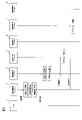
- FIG. 1 is a power supply system diagram of a redundant system 100 according to the present embodiment mounted on an electric vehicle.
- the redundant system 100 may be a system mounted on a vehicle, and the drive source of the vehicle is not particularly limited.
- the redundant system 100 may be mounted on a hybrid vehicle or a gasoline vehicle.
- the electric vehicle has an autonomous driving control function, and can drive in an automatic driving mode according to a driving support level.
- the driving support level is a level indicating the degree of intervention when the driving support device supports the driving of the vehicle by the autonomous driving control function. The higher the driving support level, the lower the driver's contribution to the driving of the vehicle.
- the driving support level can be set using the definition based on SAE J3016 of the American Society of Automotive Engineers (SAE).
- SAE American Society of Automotive Engineers
- the driving support level realized by the driving support device will be described as the driving support level 3.
- driving assistance level 3 the system performs all driving tasks, but the driver needs to regain control of the driving and prepare to drive manually when requested by the system.
- a redundant function for continuing autonomous driving in the remaining system in which the abnormality has not occurred is required.
- Examples of the system having a redundant function include a completely redundant system.
- devices necessary for autonomous driving of the vehicle for example, a driving support device, a drive control device, and a sensor are provided for normal use and for backup.
- a completely redundant system the number of devices mounted on the vehicle increases, which affects the cost of the vehicle.
- the proportion of the device occupying the space in the vehicle increases, which affects the layout inside the vehicle.
- the cost can be reduced and the degree of freedom in layout can be increased without impairing the operation safety performance by the configuration described below. ..
- the power system of an electric vehicle will be described with reference to FIG.
- the electric vehicle includes a drive battery 1 as a drive source. As shown in FIG. 1, the drive battery 1 is connected to the first power supply system 3 and the second power supply system 4 via the DCDC converter 2.
- the voltage of the drive battery 1 is input to the DCDC converter 2.
- the DCDC converter 2 is a converter that steps down the voltage of the drive battery 1.
- the voltage stepped down by the DCDC converter 2 is output to the first battery 5 connected to the first power supply system 3 and the second battery 6 connected to the second power supply system 4.
- the first battery 5 and the second battery 6 are charged by the electric power from the driving battery 1.
- the redundant system 100 of this embodiment has a first power supply system 3 and a second power supply system 4.
- Each of the first power supply system 3 and the second power supply system 4 is a power supply system composed of a single power source different from each other.
- the voltage of the first power supply system 3 and the voltage of the second power supply system 4 will be described as the same voltage, but even if the voltage of the first power supply system 3 and the voltage of the second power supply system 4 are different voltages. good.
- the redundant system 100 may have at least two power supply systems, and the redundant system 100 may have other power supply systems in addition to the first power supply system 3 and the second power supply system 4.
- the first power supply system 3 is a power supply system configured by using the first battery 5 as a power source.
- a first battery 5 and a first vehicle-mounted device group 8 are connected to the first power supply system 3.
- the first vehicle-mounted device group 8 is connected to the first power supply system 3 and is not connected to the second power supply system 4.
- the first power supply system 3 includes wiring (also referred to as a power supply line of the first power supply system) connecting the first battery 5 and the first vehicle-mounted device group 8.
- the first battery 5 is a storage battery that supplies electric power to the first in-vehicle device group 8.
- Examples of the first battery 5 include a lead storage battery capable of outputting a voltage of 12 V, but the first battery 5 may be another storage battery.
- the first in-vehicle device group 8 will be described later.
- the second power supply system 4 is a power supply system configured with the second battery 6 as a power source.
- the second power supply system 4 is a power supply system different from the first power supply system 3.
- a second battery 6 and a second vehicle-mounted device group 9 are connected to the second power supply system 4.
- the second vehicle-mounted device group 9 is connected to the second power supply system 4 and is not connected to the first power supply system 3.
- the second power supply system 4 includes wiring (also referred to as a power supply line of the second power supply system) connecting the second battery 6 and the second vehicle-mounted device group 9.
- the second battery 6 is a storage battery that supplies electric power to the second in-vehicle device group 9.
- Examples of the second battery 6 include a lithium ion battery capable of outputting a voltage of 12 V, but the second battery 6 may be another storage battery.
- the second in-vehicle device group 9 will be described later.
- the switching device 7 is a device that conducts or cuts off between the first power supply system 3 and the second power supply system 4.
- the switching device 7 operates in response to a control signal input from the first power supply monitoring ECU 14 or the second power supply monitoring ECU 24, which will be described later.
- the switching device 7 cuts off between the first power supply system 3 and the second power supply system 4.
- the switching device 7 conducts conduction between the first power supply system 3 and the second power supply system 4.
- Examples of the switching device 7 include a semiconductor switch.
- the switching device 7 is not limited to the semiconductor switch, and may be any device that can electrically connect and disconnect the power supply line of the first power supply system 3 and the power supply line of the second power supply system 4.
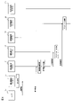
- FIG. 2 is a block diagram of the redundant system 100 according to the present embodiment.
- the redundant system 100 includes a sensor 10, an operation control main ECU 11, a braking control main ECU 12, and a steering control main ECU 13 as a main control system.
- ECU is an abbreviation for Electronic Control Unit.
- a control system including the sensor 10, the main ECU 11 for operation control, the main ECU 12 for braking control, and the main ECU 13 for steering control will be referred to as a main control system.
- the number of ECUs constituting the main control system is not limited, and the main control system may include an ECU other than the ECU shown in FIG.
- the redundant system 100 includes an operation control sub-ECU 21, a braking control sub-ECU 22, and a steering control sub-ECU 23 as sub-control systems.
- the control system including the operation control sub-ECU 21, the braking control sub-ECU 22, and the steering control sub-ECU 23 will be referred to as a sub-control system.
- the sub control system shall include at least the operation control sub ECU 21.
- the number of ECUs constituting the sub control system is not limited, and the sub control system may include an ECU other than the ECU shown in FIG.
- the redundant system 100 includes a first power supply monitoring ECU 14 that monitors the voltage of the first power supply system 3 and a second power supply monitoring ECU 24 that monitors the voltage of the second power supply system 4.
- the redundant system 100 includes a sensor 10, a detection ECU 31, and a selection ECU 32.
- Each device shown in FIG. 2 is connected by, for example, a CAN (Controller Area Network) or other in-vehicle network (Ethernet, etc.) in order to transmit and receive information to and from each other.
- CAN Controller Area Network
- Ethernet Internet Protocol
- the type of the in-vehicle network is not particularly limited.
- FIG. 2 the connection relationship of each device is shown by a solid line, but each device is connected even in a place not shown by the solid line, and it is assumed that information can be transmitted and received to each other.
- the sensor 10 is a sensor that operates on the electric power of the second battery 6 and detects surrounding information of the vehicle.
- the type and number of sensors constituting the sensor 10 are not particularly limited.
- the sensor 10 may be composed of one type or a plurality of types of sensors.
- the sensor 10 may be composed of one or a plurality of sensors of the same type.
- the sensor 10 may be composed of a plurality of a plurality of types of sensors.
- the "sensor 10" can be replaced with the "sensor group 10" in the following description.
- the senor 10 is a front camera that captures the front of the vehicle, a front radar that detects the distance from the vehicle to the preceding vehicle or an obstacle in front of the vehicle by radio waves, and a preceding vehicle from the vehicle to the front of the vehicle by laser light. Includes at least one of the forward lidars that detect the distance to the vehicle or an obstacle.
- the sensor 10 may include at least the above-mentioned sensor provided in front of the vehicle.
- the sensor 10 includes a sensor provided on the side of the vehicle (side camera, side radar, side lidar) and a sensor provided on the rear side of the vehicle (side camera, side radar, side lidar) in addition to the sensor provided on the front side of the vehicle.
- the surrounding information of the vehicle detected by the sensor 10 includes information on roads such as lane boundaries and road shapes, information on traffic rules such as signals and road signs, and traveling of vehicles such as preceding vehicles, oncoming vehicles, bicycles, and pedestrians. Contains information about obstacles to.
- the surrounding information of the vehicle is output to the operation control main ECU 11 and the operation control sub-ECU 21 at predetermined time intervals.
- the devices having the name of ECU include a ROM (Read Only Memory) in which a program for executing each control is stored, and a CPU (Central Processing Unit) stored in this ROM. It consists of a RAM (Random Access Memory) that functions as an accessible storage device.
- ROM Read Only Memory
- CPU Central Processing Unit
- Each ECU is a so-called computer, and in the following description, the "ECU” part in the name of each ECU may be read as “control device”, “controller”, “control unit”, or “processor”. ..
- the expression “operation control main ECU 11” means “operation control main control device", “operation control main controller 11", “operation control main control unit 11", and the like. Or, it is synonymous with the expression “main processor 11 for operation control”. Since the other ECUs are the same as the explanations using the main ECU 11 for operation control, the explanations will be incorporated.
- the main ECU 11 for operation control is a main computer that operates with the electric power of the first battery 5 and has an autonomous operation control function.
- the operation control main ECU 11 is a main body that drives a vehicle that travels autonomously.
- the autonomous driving control function provided in the main ECU 11 for driving control is, for example, a lane center maintenance function that controls steering so as to drive near the center of the lane, a lane keeping function that controls a lateral position so as to drive in the same lane, and driving.
- Lane change support function to move from one lane to another lane, overtaking support function to move forward by passing next to another vehicle in front (adjacent lane), autonomous lane to follow the route to the destination It includes a route driving support function for changing, and a preceding vehicle tracking function for traveling while maintaining a predetermined distance between the preceding vehicle traveling in front of the own vehicle on the same lane and the own vehicle.
- the detection result of the sensor 10 is input to the operation control main ECU 11.
- the operation control main ECU 11 executes a process for driving the vehicle along a predetermined target track based on the detection result of the sensor 10 by the autonomous operation control function.
- the predetermined target trajectory may be a target trajectory calculated by the main ECU 11 for operation control, or may be a target trajectory calculated by another ECU (not shown).
- the main ECU 11 for driving control calculates the lateral position of the vehicle based on the detection result of the sensor 10 by the autonomous driving control function, and grasps the relative positional relationship between the lane and the lane boundary line.
- the lateral position of the vehicle is the relative position of the vehicle with respect to the lane boundary lines existing on the left and right sides of the vehicle, and is the position of the vehicle along the direction orthogonal to the traveling direction of the vehicle.
- the operation control main ECU 11 calculates a target braking value and a target steering value for traveling in the same lane based on the lateral position of the vehicle.
- the same lane means that the vehicle is in the same lane as the vehicle is in.
- the lane boundary line is a boundary that distinguishes a lane in which a vehicle travels from a lane other than the lane.
- the form of the lane boundary is not particularly limited, and the lane boundary includes a white line on the road surface, a guardrail, a curb, and a median strip.
- the main ECU 11 for driving control calculates the vertical position of the vehicle based on the detection result of the sensor 10 by the autonomous driving control function, and grasps the relative positional relationship between the vehicle and the preceding vehicle.
- the vertical position of the vehicle is the relative position of the vehicle with respect to the preceding vehicle on the same lane, and is the position of the vehicle along the traveling direction of the vehicle.
- the operation control main ECU 11 calculates a target braking value and a target steering value for maintaining the inter-vehicle distance with the preceding vehicle at a predetermined distance based on the vertical position of the vehicle.
- the target braking value and the target steering value calculated by the operation control main ECU 11 are output to the selection ECU 32.
- the preceding vehicle is a vehicle traveling in front of the vehicle in the same lane.
- the operation control main ECU 11 is provided with a storage device 11a for storing past calculation results by the operation control main ECU 11.
- a storage device 11a for storing past calculation results by the operation control main ECU 11.
- Examples of the storage device 11a include RAM, ROM, and HDD (Hard Disk Drive), which are volatile storage media, and flash memory (Flash Memory), which is a non-volatile storage medium.
- the type of the storage device 27 is not particularly limited.
- the main ECU 11 for operation control stores the horizontal position of the vehicle, the vertical position of the vehicle, the target braking value, the target steering value, and the like as calculation results in the storage device 11a at a predetermined cycle.
- the braking control main ECU 12 is a main computer that operates on the electric power of the first battery 5 and has an autonomous braking control function.
- a target braking value is input to the braking control main ECU 12 from the operation control main ECU 11 or the operation control sub-ECU 21 via the selection ECU 32.
- the braking control main ECU 12 controls the braking of the vehicle by controlling the operation of the brake actuator based on the target braking value.
- the braking control main ECU 12 may have a function of controlling the operation of the drive mechanism for adjusting the acceleration / deceleration of the vehicle and the vehicle speed (in the case of an electric vehicle, the operation of the traveling motor).
- the steering control main ECU 13 is a main computer that operates on the electric power of the second battery 6 and has an autonomous steering control function.
- a target steering value is input to the steering control main ECU 13 from the operation control main ECU 11 or the operation control sub-ECU 21 via the selection ECU 32.
- the steering control main ECU 13 controls the steering of the vehicle by controlling the operation of the steering actuator based on the target steering value.
- the first power supply monitoring ECU 14 is a computer for monitoring that power is supplied to the first power supply system 3. Specifically, the first power supply monitoring ECU 14 monitors the output voltage of the first battery 5 based on the detection result of the voltage sensor (not shown) connected to the first power supply system 3. The output voltage of the first battery 5 is the voltage of the power supply line of the first power supply system 3.
- the first power supply monitoring ECU 14 When the voltage of the power supply line of the first power supply system 3 is within a predetermined range, the first power supply monitoring ECU 14 sends a signal indicating that the first power supply system 3 is normal to the operation control main ECU 11 and the operation control. Output to the sub ECU 21. On the other hand, when the voltage of the power supply line of the first power supply system 3 is out of the predetermined range, the first power supply monitoring ECU 14 sends a signal indicating that an abnormality has occurred in the first power supply system 3 to the operation control main ECU 11 and Output to the operation control sub-ECU 21 and the detection ECU 31.
- the output terminal of the DCDC converter 2 connected to the first power supply system 3 or the wire harness constituting the power supply line of the first power supply system 3 Is short-circuited to ground (Short Fail), and when the output terminal of the DCDC converter 2 and the first power supply system 3 are electrically cut off (Open Fail), the output voltage of the DCDC converter 2 is out of the predetermined range.
- the predetermined range is a range set based on the voltage of the first battery 5 and the rules regarding the operational safety of the vehicle.
- the operation control sub-ECU 21 is a sub-computer that operates on the electric power of the second battery 6 and has an autonomous operation control function.
- the operation control sub-ECU 21 is a backup ECU used in place of the operation control main ECU 11 when an abnormality related to the operation control main ECU 11 is detected by the detection ECU 31.
- the detection ECU 31 detects an abnormality related to the operation control main ECU 11
- the operation control sub-ECU 21 requests the driver to regain control of the operation, and the operation control is performed until the driver regains the control of the operation. Instead of the main ECU 11, it becomes the main driver of the vehicle.
- the autonomous operation control function included in the operation control sub-ECU 21 may be completely the same as or similar to the autonomous operation control function provided in the operation control main ECU 11, or one of the autonomous operation control functions included in the operation control main ECU 11. It may be a department.
- the operation control main ECU 11 and the operation control sub-ECU 21 operate independently without being affected by each other.
- the detection result of the sensor 10 is input to the operation control sub-ECU 21.
- the operation control sub-ECU 21 executes a process for autonomously driving the vehicle based on the detection result of the sensor 10.
- the operation control sub-ECU 21 is a process for maintaining the relative positional relationship between the vehicle and the lane boundary line before and after the detection ECU 31, which will be described later, detects an abnormality related to the main control system by the autonomous operation control function.
- the operation control sub-ECU 21 calculates the lateral position of the vehicle based on the detection result of the sensor 10 and grasps the relative positional relationship between the vehicle and the lane boundary line.
- the operation control sub-ECU 21 calculates a target braking value and a target steering value for traveling in the same lane based on the lateral position of the vehicle.
- the operation control sub-ECU 21 is a process for maintaining a relative positional relationship between the vehicle and the preceding vehicle before and after the detection ECU 31, which will be described later, detects an abnormality related to the main control system by the autonomous operation control function. To execute.
- the operation control sub-ECU 21 calculates the vertical position of the vehicle based on the detection result of the sensor 10 and grasps the relative positional relationship between the vehicle and the preceding vehicle.
- the operation control sub-ECU 21 calculates a target braking value and a target steering value for maintaining a predetermined distance between the vehicle and the preceding vehicle based on the vertical position of the vehicle.
- the target braking value and the target steering value calculated by the operation control sub-ECU 21 are output to the selection ECU 32.
- the braking control sub-ECU 22 is a sub-computer that operates on the electric power of the second battery 6 and has an autonomous braking control function.
- the braking control sub-ECU 22 is a backup ECU used in place of the braking control main ECU 12 when an abnormality related to the braking control main ECU 12 is detected by the detection ECU 31.
- the target braking value is input to the braking control sub-ECU 22 from the operation control main ECU 11 or the operation control sub-ECU 21 via the selection ECU 32.
- the braking control sub-ECU 22 controls the brake actuator based on the target braking value by the autonomous braking control function. It is preferable that the autonomous braking control function included in the braking control sub-ECU 22 is completely the same as the autonomous braking control function provided in the braking control main ECU 12.
- the steering control sub-ECU 23 is a sub-computer that operates on the electric power of the first battery 5 and has an autonomous steering control function.
- the steering control sub-ECU 23 is a backup ECU used in place of the steering control main ECU 13 when an abnormality related to the steering control main ECU 13 is detected by the detection ECU 31.
- the target steering value is input to the steering control sub-ECU 23 from the operation control main ECU 11 or the operation control sub-ECU 21 via the selection ECU 32.
- the steering control sub-ECU 23 controls the steering actuator based on the target steering value by the autonomous steering control function. It is preferable that the autonomous steering control function included in the steering control sub-ECU 23 is completely the same as the autonomous steering control function provided in the steering control main ECU 13.
- the second power supply monitoring ECU 24 is a computer for monitoring that power is supplied to the second power supply system 4. Specifically, the second power supply monitoring ECU 24 monitors the output voltage of the second battery 6 based on the detection result of the voltage sensor (not shown) connected to the second power supply system 4. The output voltage of the second battery 6 is the voltage of the power supply line of the second power supply system 4.
- the second power supply monitoring ECU 24 outputs a signal indicating that the second power supply system 4 is normal to the operation control main ECU 11 and the operation control sub-ECU 21 when the voltage of the second power supply system 4 is within a predetermined range. do.
- the second power supply monitoring ECU 24 sends a signal indicating that an abnormality has occurred in the second power supply system 4 to the operation control main ECU 11 and the operation control sub. It is output to the ECU 21 and the detection ECU 31.
- the detection ECU 31 is a computer that operates on the electric power of the second battery 6 and detects an abnormality related to the main control system.
- the abnormality related to the main control system includes an abnormality related to the sensor 10, an abnormality related to the operation control main ECU 11, an abnormality related to the braking control main ECU 12, and an abnormality related to the steering control main ECU 13.
- the abnormality related to the sensor 10 includes an abnormality of the sensor 10, an abnormality of the in-vehicle network connected to the sensor 10, and an abnormality of the second power supply system 4.
- the abnormality related to the operation control main ECU 11 includes an abnormality of the operation control main ECU 11, an abnormality of the vehicle-mounted network connected to the ECU, and an abnormality of the first power supply system 3.
- the abnormality related to the braking control main ECU 12 includes an abnormality of the braking control main ECU 12, an abnormality of the vehicle-mounted network connected to the ECU, and an abnormality of the first power supply system 3.
- the abnormality related to the steering control main ECU 13 includes an abnormality of the steering control main ECU 13, an abnormality of the vehicle-mounted network connected to the ECU, and an abnormality of the second power supply system 4.
- the abnormality of the in-vehicle network includes a communication failure and a physical connection failure of the network.
- the detection ECU 31 is connected from the operation control main ECU 11 to a signal indicating an abnormality of at least one of the operation control main ECU 11, the braking control main ECU 12, and the steering control main ECU 13, or an ECU thereof.
- a signal indicating an abnormality in the in-vehicle network determines that an abnormality has occurred in the main control system.
- the detection ECU 31 receives a signal indicating an abnormality of the first power supply system 3 from the first power supply monitoring ECU 14, or a signal indicating an abnormality of the second power supply system 4 from the second power supply monitoring ECU 24. Is input, it is determined that an abnormality has occurred in the main control system.
- the detection ECU 31 determines that an abnormality has occurred in the main control when a signal indicating an abnormality of the sensor 10 or a signal indicating an abnormality of the vehicle-mounted network connected to the sensor 10 is input from the sensor 10.
- the detection ECU 31 determines that an abnormality has occurred in the main control system
- the detection ECU 31 outputs a signal indicating that it is difficult or impossible to continue the operation control of the vehicle by the main control system to the selection ECU 32.
- the detection ECU 31 outputs a signal to which the selection ECU 32 can determine the type of abnormality to the selection ECU 32.
- the detection ECU 31 determines that no abnormality has occurred in the main control system when the above signals are not input from the operation control main ECU 11, the first power supply monitoring ECU 14, the second power supply monitoring ECU 24, and the sensor 10. do.
- the selection ECU 32 is a computer for selecting an operation target ECU. Further, the selection ECU 32 is a computer for selecting a target braking value and a target steering value to be transferred to the operation target ECU. The selection ECU 32 selects the braking control ECU to be operated based on the signal input from the detection ECU 31, and selects the steering control ECU to be operated. Further, the selection ECU 32 selects a target braking value to be transferred to the operation target braking control ECU based on the signal input from the detection ECU 31, and selects a target steering value to be transferred to the operation target steering control ECU. ..
- the selection ECU 32 transfers the target braking value calculated by the operation control main ECU 11 to the braking control main ECU 12, and the target steering calculated by the operation control main ECU 11. The value is transferred to the steering control main ECU 13. The operation of the selection ECU 32 will be described later.
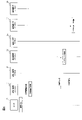
- FIGS. 3 to 6 the operation of the redundant system 100 when an abnormality has not occurred in the main control system and the operation of the redundant system 100 when an abnormality has occurred in the main control system will be described.
- the devices corresponding to the devices shown in FIG. 2 are designated by the same reference numerals as those shown in FIG.
- FIG. 3 is an explanatory diagram showing the operation of the redundant system 100 when no abnormality has occurred in the main control system. As shown in FIG. 3, ambient information is input from the sensor 10 to the operation control main ECU 11 and the operation control sub-ECU 21.
- the operation control main ECU 11 calculates the horizontal position and the vertical position of the vehicle based on the detection result of the sensor 10, and calculates the target braking value and the target steering value based on the calculated horizontal position and the vertical position of the vehicle. Further, the operation control main ECU 11 stores the calculation result in the storage device 11a. The operation control main ECU 11 outputs the target braking value and the target steering value to the selection ECU 32.
- the operation control sub-ECU 21 calculates the horizontal position and the vertical position of the vehicle based on the detection result of the sensor 10, and calculates the target braking value and the target steering value based on the calculated horizontal position and the vertical position of the vehicle.
- the operation control sub-ECU 21 outputs the target braking value and the target steering value to the selection ECU 32.
- the selection ECU 32 transfers the target braking value calculated by the operation control main ECU 11 to the braking control main ECU 12.
- the target steering value calculated by the operation control main ECU 11 is transferred to the steering control main ECU 13.
- the brake control main ECU 12 controls the brake actuator based on the input target braking value. Further, the steering control main ECU 13 controls the steering actuator based on the input target steering value.
- the operation of the redundant system 100 shown in FIG. 3 is executed at predetermined intervals. As a result, the vehicle can autonomously travel along a predetermined target track, and automatic driving according to the driving support level 3 can be realized.
- FIG. 4 is an explanatory diagram illustrating the operation of the redundant system 100 when an abnormality occurs in the operation control main ECU 11.
- the operation control main ECU 11 When some abnormality occurs in the operation control main ECU 11, the operation control main ECU 11 outputs a signal indicating the abnormality of the operation control main ECU 11 to the detection ECU 31 by the self-diagnosis function.
- the detection ECU 31 outputs a signal indicating that an abnormality has occurred in the main control system to the selection ECU 32.
- the operation control main ECU 11 notifies the driver that an abnormality has occurred in the main control system, and requests the driver to regain control of the operation (also referred to as a takeover request).
- the operation control main ECU 11 makes a takeover request to the driver by displaying a warning light at a predetermined position on the instrument panel.
- the operation control sub-ECU 21 calculates the horizontal position and the vertical position of the vehicle based on the detection result of the sensor 10, and calculates the target braking value and the target steering value based on the calculated horizontal position and the vertical position of the vehicle.
- the operation control sub-ECU 21 outputs the target braking value and the target steering value to the selection ECU 32.
- the target braking value and the target steering value calculated by the driving control sub-ECU 21 are the target braking value and the target steering value for preventing the vehicle from deviating from the lane from the time when the driver makes a takeover request to the time when the driver regains control of driving. This is the target steering value.
- the target braking value and the target steering value calculated by the driving control sub-ECU 21 are obtained from the time when the driver makes a takeover request to the time when the driver regains control of driving. It is a target braking value and a target steering value for maintaining the inter-vehicle distance between the vehicle and the preceding vehicle at a predetermined distance.
- the selection ECU 32 selects the braking control main ECU 12 as the operation target braking control ECU and controls the operation target steering.
- the steering control main ECU 13 is selected as the steering ECU. Further, the selection ECU 32 transfers the target braking value calculated by the operation control sub-ECU 21 to the braking control main ECU 12, and transfers the target steering value calculated by the operation control sub-ECU 21 to the steering control main ECU 13. ..
- the brake control main ECU 12 controls the brake actuator based on the input target braking value. Further, the steering control main ECU 13 controls the steering actuator based on the input target steering value.
- the operation of the redundant system 100 shown in FIG. 4 can be used not only when an abnormality occurs in the operation control main ECU 11 but also when an abnormality occurs in the in-vehicle network connected to the operation control main ECU 11. can.
- a signal indicating that an abnormality has occurred in the vehicle-mounted network connected to the operation control main ECU 11 is input from the operation control main ECU 11 to the detection ECU 31.
- FIG. 5 is an explanatory diagram illustrating the operation of the redundant system 100 when an abnormality occurs in the first power supply system 3.
- the operation control main ECU 11, the braking control main ECU 12, and the steering control sub-ECU 23 driven by the electric power of the first battery 5 will be described as being unable to operate normally. That is, when an abnormality occurs in the first power supply system 3, each of the operation control main ECU 11, the braking control main ECU 12, and the steering control sub-ECU 23 is in the same state as when the abnormality occurs.
- the first power supply monitoring ECU 14 When an abnormality occurs in the first power supply system 3, the first power supply monitoring ECU 14 outputs a signal indicating the abnormality in the first power supply system 3 to the detection ECU 31.
- the detection ECU 31 outputs a signal indicating that an abnormality has occurred in the main control system to the selection ECU 32.
- the operation control sub-ECU 21 instead of the operation control main ECU 11, the operation control sub-ECU 21 makes a takeover request to the driver. If the operation control main ECU 11 can operate, the operation control main ECU 11 may make a takeover request to the driver.
- the first power supply monitoring ECU 14 outputs a control signal to the switching device 7 when an abnormality occurs in the first power supply system 3.
- the switching device 7 cuts off between the first power supply system 3 and the second power supply system 4.
- the switching device 7 cuts off between the first power supply system 3 and the second power supply system 4
- the first battery 5 supplies electric power according to the remaining charge to the first in-vehicle device group 8 and the second battery. 6 supplies electric power according to the remaining charge to the second in-vehicle device group 9.
- the operation control of the vehicle is continued by at least the second in-vehicle device group 9 from the time when the takeover request is made to the driver until the driver regains the control of the operation.
- the selection ECU 32 selects the braking control sub-ECU 22 as the braking control ECU to be operated, and the steering control ECU to be operated.
- the main ECU 13 for steering control is selected as. Further, the selection ECU 32 transfers the target braking value calculated by the operation control sub-ECU 21 to the braking control sub-ECU 22, and transfers the target steering value calculated by the operation control sub-ECU 21 to the steering control main ECU 13. ..
- the brake control sub-ECU 22 controls the brake actuator based on the input target braking value. Further, the steering control main ECU 13 controls the steering actuator based on the input target steering value.
- FIG. 6 is an explanatory diagram illustrating the operation of the redundant system 100 when an abnormality occurs in the sensor 10.
- the sensor 10 When some abnormality occurs in the sensor 10, the sensor 10 outputs a signal indicating the abnormality of the sensor 10 to the detection ECU 31.
- the detection ECU 31 outputs a signal indicating an abnormality of the sensor 10 to the selection ECU 32.
- the operation control main ECU 11 makes a takeover request to the driver.
- the operation control main ECU 11 calculates the horizontal position and the vertical position of the vehicle based on the past calculation results stored in the storage device 11a. For example, the operation control main ECU 11 rearranges the horizontal position and the vertical position of the vehicle stored in the storage device 11a in the order of the time system example, so that the position of the lane boundary line with respect to the vehicle before the abnormality occurs in the sensor 10. And estimate the position of the preceding vehicle with respect to the vehicle.
- the driving control main ECU 11 calculates a target braking value and a target steering value based on the estimated position of the lane boundary line and the position of the preceding vehicle.
- the target braking value calculated by the operation control sub-ECU 21 is a target braking value for the vehicle to slowly decelerate from the time when the takeover request is made to the driver until the driver regains control of the operation.
- the operation control main ECU 11 outputs the target braking value and the target steering value to the selection ECU 32.
- the selection ECU 32 selects the brake control main ECU 12 as the operation target braking control ECU and steer control as the operation target steering control ECU. Main ECU 13 for selection is selected. Further, the selection ECU 32 transfers the target braking value calculated by the operation control main ECU 11 to the braking control main ECU 12, and transfers the target steering value calculated by the operation control main ECU 11 to the steering control main ECU 13. ..
- the brake control main ECU 12 controls the brake actuator based on the input target braking value. Further, the steering control main ECU 13 controls the steering actuator based on the input target steering value.
- the driver controls the operation after making a takeover request to the driver without using the sensor.
- the vehicle can continue to run autonomously until it is regained. That is, in the redundant system 100, even if the backup sensor is not provided, the same operation safety performance as in the case where the backup sensor is provided can be maintained. Further, in the redundant system 100, a space for providing a backup sensor becomes unnecessary, and the degree of freedom in layout can be increased. Moreover, since the number of devices mounted on the vehicle can be reduced, the cost can be reduced.
- the redundant system 100 is mounted on a vehicle that can travel autonomously, and has a first power supply system 3 and a second power supply system 4. Further, the redundant system 100 is an operation used as a substitute for the operation control main ECU 11 when an abnormality related to the operation control main ECU 11 for executing the process for autonomously traveling the vehicle and the operation control main ECU 111 is detected.
- a control sub-ECU 21 is provided. In the present embodiment, the operation control main ECU 11 is connected to the first power supply system 3 and not connected to the second power supply system 4, and the operation control sub-ECU 21 is connected to the second power supply system 4. 1 Not connected to the power supply system 3.
- each of the operation control main ECU 11 and the operation control sub-ECU 21 is connected to the first power supply system 3 or the second power supply system 4 which is a single power supply system, it is between the operation control ECU and the power supply system.
- the connection relationship can be simplified and the system design scale can be reduced.
- the redundant system 100 includes a sensor 10 that detects information around the vehicle and outputs the detection result to the operation control main ECU 11 and the operation control sub-ECU 21.
- the sensor 10 is connected to the second power supply system 4 and not connected to the first power supply system 3.
- the target braking value input to the braking control ECU is used for operation control from the target braking value calculated by the operation control main ECU 11. It may switch to the target braking value calculated by the sub ECU 21. The same applies to the target steering value input to the steering control ECU.
- the horizontal position and vertical position of the vehicle calculated by the main ECU 11 for operation control may not always match the horizontal position and vertical position of the vehicle calculated by the sub ECU 21 for operation control. In such a case, an error occurs in the horizontal position and the vertical position of the vehicle before and after the abnormality occurs in the main control system. Therefore, the operation control sub-ECU 21 is used to maintain the continuity of the horizontal position and the vertical position of the vehicle. , It is necessary to correct the horizontal position and the vertical position of the vehicle based on the detection result of the sensor 10. In the present embodiment, since the sensor 10 is connected to the second power supply system 4, even if an abnormality occurs in the first power supply system 3, the operation control sub-ECU 21 is on the side of the vehicle based on the detection result of the sensor 10.
- the position and vertical position can be corrected.
- the vehicle deviates from the lane because the relative positional relationship between the lane boundary and the vehicle can be maintained from the time the driver makes a takeover request to the time the driver regains control of driving. Can be prevented.
- the redundant system 100 includes a detection ECU 31 for detecting an abnormality related to the main control system.
- the abnormality related to the main control system includes at least one of an abnormality related to the main ECU 11 for operation control, an abnormality related to the first power supply system 3, and an abnormality related to the sensor 10.
- the senor 10 detects a lane boundary line, which is a boundary between the lane in which the vehicle is traveling and a lane other than the lane, as information around the vehicle. Further, the operation control sub-ECU 21 executes a process for maintaining the relative positional relationship between the vehicle and the lane boundary line before and after the detection ECU 31 detects an abnormality related to the main control system. This allows the vehicle to stay in the lane from the time the driver makes a takeover request until the driver regains control of driving.
- the senor 10 detects a preceding vehicle traveling in front of the vehicle in the same lane as the vehicle traveling as information around the vehicle. Further, the operation control sub-ECU 21 executes a process for maintaining the relative positional relationship between the vehicle and the preceding vehicle before and after the detection ECU 31 detects an abnormality related to the main control system. As a result, the vehicle can travel while maintaining the inter-vehicle distance from the preceding vehicle from the time when the takeover request is made to the driver until the driver regains control of driving.
- the operation control main ECU 11 has a storage device 11a for storing past calculation results by the operation control main ECU 11.
- the detection ECU 31 detects an abnormality related to the sensor 10
- the operation control main ECU 11 calculates the position of the vehicle on the lane based on the calculation result stored in the storage device 11a.
- the vehicle can be used from the time when the takeover request is made to the driver until the driver regains control of the driving. You can drive without departing from the lane.
- the redundant system 100 includes a switching device 7 that conducts or cuts off the first power supply system 3 and the second power supply system 4.
- the operation control sub-ECU 21 controls the switching device 7 to shut off between the first power supply system and the second power supply system.
- the in-vehicle device group 9 enables the vehicle to continue to run autonomously.
- the redundant system 100 includes a steering control main ECU 13 that controls the steering of the vehicle and steering control based on the control of the operation control main ECU 11 or the target steering value input from the operation control sub-ECU 21.
- a sub-ECU 23 for steering control used as a substitute for the main ECU 13 for steering control is provided.
- the steering control main ECU 13 is connected to the second power supply system 4 and not connected to the first power supply system 3, and the steering control sub ECU 23 is connected to the first power supply system 3 and connected to the second power supply system 4. Not connected.
- the first power supply monitoring ECU 14 and the second power supply monitoring ECU 24 have been described as devices for detecting an abnormality in the first power supply system 3 or an abnormality in the second power supply system 4, but the first power supply monitoring is performed.
- the ECU 14 and the second power supply monitoring ECU 24 may be used for other purposes.
- the first power supply monitoring ECU 14 may be used to determine the start of control by the operation control main ECU 11. For example, when the ignition of the vehicle is turned on and the voltage of the first power supply system 3 rises, the operation control main ECU 11 determines that the first power supply monitoring ECU 14 is supplying power to the first power supply system 3. If so, the process for driving the vehicle autonomously may be started. In this case, after the ignition of the vehicle is turned on, a signal indicating that the first power supply system 3 is normal is input from the first power supply monitoring ECU 14 to the operation control main ECU 11 for the first time. Since the main ECU 11 for operation control can start the process in a state where sufficient electric power is supplied from the first battery 5, it is possible to reduce the possibility that the behavior of the vehicle suddenly changes after the ignition is turned on. ..
- first power supply monitoring ECU 14 and the second power supply monitoring ECU 24 may be used to determine the end of control by the operation control main ECU 11. For example, when the ignition of the vehicle is turned off and the voltage of the first power supply system 3 and the voltage of the second power supply system 4 drop, the operation control main ECU 11 has the first power supply monitoring ECU 14 as the first power supply system 3. The process for autonomously driving the vehicle is executed until it is determined that the electric power is not supplied and the second power supply monitoring ECU 24 determines that the electric power is not supplied to the second power supply system 4. May be good.
- a signal indicating an abnormality in the first power supply system 3 is input to the operation control main ECU 11 for the first time from the first power supply monitoring ECU 14, and also from the second power supply monitoring ECU 24.
- a signal indicating an abnormality in the second power supply system 4 is input for the first time.
- the operation control main ECU 11 can continue the process until the power is not supplied to any of the first power supply system 3 and the second power supply system 4. Further, even if an abnormality occurs in the first power supply system 3, it is possible to prevent the operation control main ECU 11 from stopping the process.
- the configuration of the redundant system 100 in which the steering control main ECU 13 is provided on the second power supply system 4 side and the steering control sub-ECU 23 is provided on the first power supply system 3 side has been described as an example.
- the redundant system 100 may be configured such that the steering control main ECU 13 is provided on the first power supply system 3 side and the steering control sub ECU 23 is provided on the second power supply system 4 side.
- the redundant system 100 is mounted on a vehicle capable of realizing the driving support level 3
- the redundant system 100 is mounted on the vehicle capable of realizing the driving support level 2.
- a vehicle having a driving support level 2 equipped with a mode in which the vehicle autonomously travels without the driver touching the steering also referred to as a hands-off mode
- a vehicle capable of achieving the driving support level 3 It is possible to obtain the same effect as the effect.
- the redundant system 100 has the operation control main ECU 11, the braking control main ECU 12, and the steering control.
- the sub-ECU 23 allows the vehicle to continue autonomous travel.
- the operation control main ECU 11 estimates the horizontal position and the vertical position of the vehicle without using the sensor 10, as in the example when an abnormality occurs in the sensor 10.
- the operation control main ECU 11 may estimate the horizontal position and the vertical position of the vehicle based on the current wheel speed and the current yaw rate.
- the information used for estimating the horizontal position and the vertical position of the vehicle is not limited to the past horizontal position and the vertical position of the vehicle calculated by the main ECU 11 for operation control, and the past calculated by the main ECU 11 for operation control. It may be a target braking value or a target steering value of the vehicle.
Abstract
Description
2…DCDCコンバータ
3…第1電源系統
4…第2電源系統
5…第1バッテリ
6…第2バッテリ
7…切換装置
8…第1車載機器群
11…運転制御用メインECU
12…制動制御用メインECU
14…第1電源監視用ECU
23…操舵制御用サブECU
9…第2車載機器群
10…センサ
13…操舵制御用メインECU
21…運転制御用サブECU
22…制動制御用サブECU
24…第2電源監視用ECU
31…検知用ECU
32…選択用ECU 1 ... Drive
12 ... Main ECU for braking control
14 ... ECU for first power supply monitoring
23 ... Sub ECU for steering control
9 ... 2nd in-
21 ... Sub ECU for operation control
22 ... Sub ECU for braking control
24 ... ECU for monitoring the second power supply
31 ... Detection ECU
32 ... ECU for selection
Claims (10)
- 自律的に走行可能な車両に搭載され、少なくとも第1電源系統及び前記第1電源系統とは異なる第2電源系統を有する冗長システムであって、
前記車両を自律的に走行させるための処理を実行する運転制御用メイン制御装置と、
前記運転制御用メイン制御装置に関する異常が検知された場合、前記運転制御用メイン制御装置の代わりとして用いられる運転制御用サブ制御装置を備え、
前記運転制御用メイン制御装置は、前記第1電源系統に接続され、前記第2電源系統に接続されておらず、
前記運転制御用サブ制御装置は、前記第2電源系統に接続され、前記第1電源系統に接続されていない
冗長システム。 A redundant system mounted on a vehicle that can travel autonomously and having at least a first power supply system and a second power supply system different from the first power supply system.
A main control device for operation control that executes processing for autonomously driving the vehicle, and
When an abnormality related to the main control device for operation control is detected, a sub control device for operation control used in place of the main control device for operation control is provided.
The operation control main control device is connected to the first power supply system and is not connected to the second power supply system.
The operation control sub-control device is a redundant system connected to the second power supply system and not connected to the first power supply system. - 請求項1に記載の冗長システムであって、
前記車両の周囲の情報を検出し、検出結果を前記運転制御用メイン制御装置及び前記運転制御用サブ制御装置に出力するセンサを備え、
前記センサは、前記第2電源系統に接続され、前記第1電源系統に接続されていない
冗長システム。 The redundant system according to claim 1.
It is provided with a sensor that detects information around the vehicle and outputs the detection result to the operation control main control device and the operation control sub control device.
The sensor is a redundant system connected to the second power supply system and not connected to the first power supply system. - 請求項2に記載の冗長システムであって、
前記運転制御用メイン制御装置を含むメイン制御系に関する異常を検知する検知用制御装置を備え、
前記メイン制御系に関する異常は、前記運転制御用メイン制御装置に関する異常、前記第1電源系統の異常、及び前記センサに関する異常のうち少なくともいずれか一つを含む
冗長システム。 The redundant system according to claim 2.
A detection control device for detecting an abnormality related to the main control system including the operation control main control device is provided.
The abnormality related to the main control system is a redundant system including at least one of an abnormality related to the operation control main control device, an abnormality related to the first power supply system, and an abnormality related to the sensor. - 請求項3記載の冗長システムであって、
前記センサは、前記車両の周囲の情報として、前記車両が走行する車線と前記車線以外との境界である車線境界線を検出し、
前記運転制御用サブ制御装置は、前記検知用制御装置が前記メイン制御系に関する異常を検知する前後で、前記車両と前記車線境界線との相対的な位置関係を維持するための処理を実行する
冗長システム。 The redundant system according to claim 3, wherein the redundant system is used.
The sensor detects a lane boundary line, which is a boundary between the lane in which the vehicle travels and a lane other than the lane, as information around the vehicle.
The operation control sub-control device executes a process for maintaining a relative positional relationship between the vehicle and the lane boundary line before and after the detection control device detects an abnormality related to the main control system. Redundant system. - 請求項3又は4に記載の冗長システムであって、
前記センサは、前記車両の周囲の情報として、前記車両が走行する車線と同一車線で前記車両の前方を走行する先行車両を検出し、
前記運転制御用サブ制御装置は、前記検知用制御装置が前記メイン制御系に関する異常を検知する前後で、前記車両と前記先行車両との相対的な位置関係を維持するための処理を実行する
冗長システム。 The redundant system according to claim 3 or 4, wherein the redundant system is used.
The sensor detects, as information around the vehicle, a preceding vehicle traveling in front of the vehicle in the same lane as the vehicle in which the vehicle is traveling.
The operation control sub-control device is redundant in executing a process for maintaining a relative positional relationship between the vehicle and the preceding vehicle before and after the detection control device detects an abnormality in the main control system. system. - 請求項3~5のいずれかに記載の冗長システムであって、
前記運転制御用メイン制御装置は、
前記運転制御用メイン制御装置による過去の演算結果を記憶する記憶装置を有し、
前記検知用制御装置が前記センサに関する異常を検知した場合、前記記憶装置に記憶された前記演算結果に基づいて、前記車両が走行する車線上での前記車両の位置を推定する
冗長システム。 The redundant system according to any one of claims 3 to 5.
The main control device for operation control is
It has a storage device for storing past calculation results by the main control device for operation control.
A redundant system that estimates the position of the vehicle on the lane in which the vehicle travels based on the calculation result stored in the storage device when the detection control device detects an abnormality related to the sensor. - 請求項3~6のいずれかに記載の冗長システムであって、
前記第1電源系統と前記第2電源系統を導通又は遮断する切換装置を備え、
前記運転制御用サブ制御装置は、前記検知用制御装置が前記第1電源系統の異常を検知した場合、前記切換装置を制御することで前記第1電源系統と前記第2電源系統の間を遮断させる
冗長システム。 The redundant system according to any one of claims 3 to 6.
A switching device for conducting or disconnecting the first power supply system and the second power supply system is provided.
When the detection control device detects an abnormality in the first power supply system, the operation control sub control device controls the switching device to cut off between the first power supply system and the second power supply system. Redundant system to let. - 請求項1~7のいずれかに記載の冗長システムであって、
前記運転制御用メイン制御装置又は前記運転制御用サブ制御装置から入力される目標操舵値に基づき、前記車両のステアリングを制御する操舵制御用メイン制御装置と、
前記操舵制御用メイン制御装置に関する異常が検知された場合、前記操舵制御用メイン制御装置の代わりとして用いられる操舵制御用サブ制御装置を備え、
前記操舵制御用メイン制御装置は、前記第2電源系統に接続され、前記第1電源系統に接続されておらず、
前記操舵制御用サブ制御装置は、前記第1電源系統に接続され、前記第2電源系統に接続されていない
冗長システム。 The redundant system according to any one of claims 1 to 7.
A steering control main control device that controls the steering of the vehicle based on a target steering value input from the operation control main control device or the operation control sub control device.
When an abnormality related to the steering control main control device is detected, a steering control sub-control device used in place of the steering control main control device is provided.
The steering control main control device is connected to the second power supply system and is not connected to the first power supply system.
The steering control sub-control device is a redundant system connected to the first power supply system and not connected to the second power supply system. - 請求項1~8のいずれか記載の冗長システムであって、
前記第1電源系統の状態を監視する第1監視装置を備え、
前記運転制御用メイン制御装置は、前記第1監視装置が前記第1電源系統に電力が供給されていると判定した場合、前記車両を自律的に走行させるための前記処理を開始する
冗長システム。 The redundant system according to any one of claims 1 to 8.
A first monitoring device for monitoring the state of the first power supply system is provided.
The operation control main control device is a redundant system that starts the process for autonomously traveling the vehicle when the first monitoring device determines that electric power is supplied to the first power supply system. - 請求項9に記載の冗長システムであって、
前記第2電源系統の状態を監視する第2監視装置を備え、
前記運転制御用メイン制御装置は、前記第1監視装置が前記第1電源系統には電力が供給されていないと判定し、かつ、前記第2監視装置が前記第2電源系統には電力が供給されていないと判定するまで、前記車両を自律的に走行させるための前記処理を実行する
冗長システム。 The redundant system according to claim 9, wherein the redundant system is used.
A second monitoring device for monitoring the state of the second power supply system is provided.
The operation control main control device determines that the first monitoring device does not supply power to the first power supply system, and the second monitoring device supplies power to the second power supply system. A redundant system that executes the process for autonomously driving the vehicle until it is determined that the vehicle has not been driven.
Priority Applications (6)
| Application Number | Priority Date | Filing Date | Title |
|---|---|---|---|
| PCT/JP2020/045205 WO2022118459A1 (en) | 2020-12-04 | 2020-12-04 | Redundant system |
| EP20964311.3A EP4258240A4 (en) | 2020-12-04 | 2020-12-04 | Redundant system |
| US18/265,166 US20240001967A1 (en) | 2020-12-04 | 2020-12-04 | Redundant System |
| JP2022566601A JPWO2022118459A1 (en) | 2020-12-04 | 2020-12-04 | |
| MX2023006372A MX2023006372A (en) | 2020-12-04 | 2020-12-04 | Redundant system. |
| CN202080107659.0A CN116508085A (en) | 2020-12-04 | 2020-12-04 | Redundancy system |
Applications Claiming Priority (1)
| Application Number | Priority Date | Filing Date | Title |
|---|---|---|---|
| PCT/JP2020/045205 WO2022118459A1 (en) | 2020-12-04 | 2020-12-04 | Redundant system |
Publications (1)
| Publication Number | Publication Date |
|---|---|
| WO2022118459A1 true WO2022118459A1 (en) | 2022-06-09 |
Family
ID=81852834
Family Applications (1)
| Application Number | Title | Priority Date | Filing Date |
|---|---|---|---|
| PCT/JP2020/045205 WO2022118459A1 (en) | 2020-12-04 | 2020-12-04 | Redundant system |
Country Status (6)
| Country | Link |
|---|---|
| US (1) | US20240001967A1 (en) |
| EP (1) | EP4258240A4 (en) |
| JP (1) | JPWO2022118459A1 (en) |
| CN (1) | CN116508085A (en) |
| MX (1) | MX2023006372A (en) |
| WO (1) | WO2022118459A1 (en) |
Citations (4)
| Publication number | Priority date | Publication date | Assignee | Title |
|---|---|---|---|---|
| JP2018504309A (en) | 2015-01-05 | 2018-02-15 | ヴァレオ・シャルター・ウント・ゼンゾーレン・ゲーエムベーハー | Architecture for driving assistance systems with conditional automation |
| JP2019089382A (en) * | 2017-11-13 | 2019-06-13 | 株式会社デンソー | Automatic operation control device, and automatic operation control method for vehicle |
| JP2019126208A (en) * | 2018-01-18 | 2019-07-25 | トヨタ自動車株式会社 | Vehicular control device |
| JP2020097352A (en) * | 2018-12-19 | 2020-06-25 | 日立オートモティブシステムズ株式会社 | Electronic control device and on-vehicle system |
-
2020
- 2020-12-04 MX MX2023006372A patent/MX2023006372A/en unknown
- 2020-12-04 US US18/265,166 patent/US20240001967A1/en active Pending
- 2020-12-04 CN CN202080107659.0A patent/CN116508085A/en active Pending
- 2020-12-04 JP JP2022566601A patent/JPWO2022118459A1/ja active Pending
- 2020-12-04 EP EP20964311.3A patent/EP4258240A4/en active Pending
- 2020-12-04 WO PCT/JP2020/045205 patent/WO2022118459A1/en active Application Filing
Patent Citations (4)
| Publication number | Priority date | Publication date | Assignee | Title |
|---|---|---|---|---|
| JP2018504309A (en) | 2015-01-05 | 2018-02-15 | ヴァレオ・シャルター・ウント・ゼンゾーレン・ゲーエムベーハー | Architecture for driving assistance systems with conditional automation |
| JP2019089382A (en) * | 2017-11-13 | 2019-06-13 | 株式会社デンソー | Automatic operation control device, and automatic operation control method for vehicle |
| JP2019126208A (en) * | 2018-01-18 | 2019-07-25 | トヨタ自動車株式会社 | Vehicular control device |
| JP2020097352A (en) * | 2018-12-19 | 2020-06-25 | 日立オートモティブシステムズ株式会社 | Electronic control device and on-vehicle system |
Also Published As
| Publication number | Publication date |
|---|---|
| US20240001967A1 (en) | 2024-01-04 |
| CN116508085A (en) | 2023-07-28 |
| EP4258240A4 (en) | 2024-04-24 |
| EP4258240A1 (en) | 2023-10-11 |
| MX2023006372A (en) | 2023-12-07 |
| JPWO2022118459A1 (en) | 2022-06-09 |
Similar Documents
| Publication | Publication Date | Title |
|---|---|---|
| US10940868B2 (en) | Vehicle control device, vehicle control method, and vehicle control program | |
| US11472428B2 (en) | Vehicle control system and control method | |
| US11285945B2 (en) | Traveling control system and control method of vehicle | |
| US11203350B2 (en) | Vehicle control system | |
| JP6364580B2 (en) | Active steering system and method for controlling vehicle travel | |
| KR102529915B1 (en) | Apparatus and method for controlling drive of vehicle | |
| JP7158105B2 (en) | travel control device | |
| US11449060B2 (en) | Vehicle, apparatus for controlling same, and control method therefor | |
| US11458861B2 (en) | Vehicle control device | |
| CN111565992A (en) | Vehicle control device | |
| KR20210007510A (en) | Redundancy brake operating system and method for breakdown of main brake of autonomous vehicle | |
| US20150151757A1 (en) | Method for Operating a Motor Vehicle During Fully Automatic Vehicle Guidance | |
| CN111497834A (en) | Driving assistance system | |
| WO2019116871A1 (en) | Vehicle, and control system and control method therefor | |
| JP2021062780A (en) | Vehicle control system | |
| US11225256B2 (en) | Vehicle control system and control method of vehicle | |
| JP7095300B2 (en) | Vehicle control system | |
| WO2022144959A1 (en) | Vehicle control apparatus, vehicle system, vehicle control method, and program | |
| CN112977475A (en) | Autonomous vehicle and control method thereof | |
| WO2022118459A1 (en) | Redundant system | |
| US20210107521A1 (en) | Vehicle control system | |
| CN113696902A (en) | Vehicle control system, vehicle control method, computer device, medium, and vehicle | |
| CN113910915A (en) | Vehicle power system | |
| JP2021062781A (en) | Vehicle control system | |
| US11904839B2 (en) | Vehicle control device, vehicle, vehicle control method, and storage medium storing control program |
Legal Events
| Date | Code | Title | Description |
|---|---|---|---|
| 121 | Ep: the epo has been informed by wipo that ep was designated in this application |
Ref document number: 20964311 Country of ref document: EP Kind code of ref document: A1 |
|
| ENP | Entry into the national phase |
Ref document number: 2022566601 Country of ref document: JP Kind code of ref document: A |
|
| WWE | Wipo information: entry into national phase |
Ref document number: 202080107659.0 Country of ref document: CN |
|
| WWE | Wipo information: entry into national phase |
Ref document number: 18265166 Country of ref document: US |
|
| REG | Reference to national code |
Ref country code: BR Ref legal event code: B01A Ref document number: 112023010270 Country of ref document: BR |
|
| ENP | Entry into the national phase |
Ref document number: 112023010270 Country of ref document: BR Kind code of ref document: A2 Effective date: 20230526 |
|
| NENP | Non-entry into the national phase |
Ref country code: DE |
|
| ENP | Entry into the national phase |
Ref document number: 2020964311 Country of ref document: EP Effective date: 20230704 |