WO2022113307A1 - データ処理装置、データ処理方法およびデータ処理プログラム - Google Patents
データ処理装置、データ処理方法およびデータ処理プログラム Download PDFInfo
- Publication number
- WO2022113307A1 WO2022113307A1 PCT/JP2020/044380 JP2020044380W WO2022113307A1 WO 2022113307 A1 WO2022113307 A1 WO 2022113307A1 JP 2020044380 W JP2020044380 W JP 2020044380W WO 2022113307 A1 WO2022113307 A1 WO 2022113307A1
- Authority
- WO
- WIPO (PCT)
- Prior art keywords
- user
- information
- unit
- data processing
- call
- Prior art date
- Legal status (The legal status is an assumption and is not a legal conclusion. Google has not performed a legal analysis and makes no representation as to the accuracy of the status listed.)
- Ceased
Links
Images








Classifications
-
- H—ELECTRICITY
- H04—ELECTRIC COMMUNICATION TECHNIQUE
- H04N—PICTORIAL COMMUNICATION, e.g. TELEVISION
- H04N7/00—Television systems
- H04N7/14—Systems for two-way working
- H04N7/15—Conference systems
-
- G—PHYSICS
- G06—COMPUTING OR CALCULATING; COUNTING
- G06F—ELECTRIC DIGITAL DATA PROCESSING
- G06F13/00—Interconnection of, or transfer of information or other signals between, memories, input/output devices or central processing units
-
- G—PHYSICS
- G06—COMPUTING OR CALCULATING; COUNTING
- G06F—ELECTRIC DIGITAL DATA PROCESSING
- G06F3/00—Input arrangements for transferring data to be processed into a form capable of being handled by the computer; Output arrangements for transferring data from processing unit to output unit, e.g. interface arrangements
- G06F3/01—Input arrangements or combined input and output arrangements for interaction between user and computer
- G06F3/048—Interaction techniques based on graphical user interfaces [GUI]
- G06F3/0481—Interaction techniques based on graphical user interfaces [GUI] based on specific properties of the displayed interaction object or a metaphor-based environment, e.g. interaction with desktop elements like windows or icons, or assisted by a cursor's changing behaviour or appearance
- G06F3/04817—Interaction techniques based on graphical user interfaces [GUI] based on specific properties of the displayed interaction object or a metaphor-based environment, e.g. interaction with desktop elements like windows or icons, or assisted by a cursor's changing behaviour or appearance using icons
-
- G—PHYSICS
- G06—COMPUTING OR CALCULATING; COUNTING
- G06F—ELECTRIC DIGITAL DATA PROCESSING
- G06F3/00—Input arrangements for transferring data to be processed into a form capable of being handled by the computer; Output arrangements for transferring data from processing unit to output unit, e.g. interface arrangements
- G06F3/01—Input arrangements or combined input and output arrangements for interaction between user and computer
- G06F3/048—Interaction techniques based on graphical user interfaces [GUI]
- G06F3/0484—Interaction techniques based on graphical user interfaces [GUI] for the control of specific functions or operations, e.g. selecting or manipulating an object, an image or a displayed text element, setting a parameter value or selecting a range
- G06F3/04847—Interaction techniques to control parameter settings, e.g. interaction with sliders or dials
-
- G—PHYSICS
- G06—COMPUTING OR CALCULATING; COUNTING
- G06F—ELECTRIC DIGITAL DATA PROCESSING
- G06F3/00—Input arrangements for transferring data to be processed into a form capable of being handled by the computer; Output arrangements for transferring data from processing unit to output unit, e.g. interface arrangements
- G06F3/16—Sound input; Sound output
- G06F3/165—Management of the audio stream, e.g. setting of volume, audio stream path
-
- H—ELECTRICITY
- H04—ELECTRIC COMMUNICATION TECHNIQUE
- H04N—PICTORIAL COMMUNICATION, e.g. TELEVISION
- H04N7/00—Television systems
- H04N7/14—Systems for two-way working
- H04N7/15—Conference systems
- H04N7/157—Conference systems defining a virtual conference space and using avatars or agents
Definitions
- the present invention relates to a data processing apparatus, a data processing method and a data processing program.
- Non-Patent Document 1 a system that realizes conversation with a small number of people (see Non-Patent Document 1) and a system that represents participants with icons on the GUI, and the sound is loud when the icons are close to each other and small when the icons are far away (non-patent).
- Reference 2 exists.
- the information for determining the user's status is only audio, video, and text, so the difference in information that can be acquired and communication. It is difficult to reproduce the office environment because the problem of the call environment due to the influence of delay cannot be solved. Therefore, there will inevitably be a gap in the communication environment between office work and telework, such as the difference in the information that can be obtained and the call environment.
- the present invention has been made in view of the above, and is a data processing device, a data processing method, and a data processing program capable of performing realistic communication simulating an environment in which a plurality of users work in the same office.
- the purpose is to provide.
- the data processing device is a creating unit that creates spatial information imitating an office environment having a plurality of rooms and each terminal device used by a plurality of users.
- a display unit that displays spatial information in which a plurality of icons corresponding to a plurality of users are arranged in the plurality of rooms based on the instruction information from, and each room in which the plurality of icons are displayed in the spatial information.
- It is provided with a call unit for connecting a plurality of terminal devices corresponding to a plurality of icons displayed in the same room to establish a call.
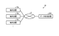
- FIG. 1 is a diagram showing a configuration of a system according to the first embodiment.
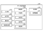
- FIG. 2 is a functional block diagram showing the configuration of the data processing apparatus according to the first embodiment.
- FIG. 3 is a diagram showing an example of an office UI.
- FIG. 4 is a diagram (1) for explaining the processing of the creating unit.
- FIG. 5 is a diagram (2) for explaining the processing of the creating unit.
- FIG. 6 is a diagram (1) for explaining an example of the movement of the icon.
- FIG. 7 is a diagram (2) for explaining an example of the movement of the icon.
- FIG. 8 is a diagram for explaining the processing of the call unit according to the first embodiment.
- FIG. 9 is a flowchart showing a processing procedure of the data processing apparatus according to the first embodiment.
- FIG. 9 is a flowchart showing a processing procedure of the data processing apparatus according to the first embodiment.
- FIG. 10 is a flowchart showing a processing procedure of the spatial information creation process.
- FIG. 11 is a flowchart showing a processing procedure of call processing.
- FIG. 12 is a diagram showing a configuration of the system according to the second embodiment.
- FIG. 13 is a functional block diagram showing the configuration of the data processing apparatus according to the second embodiment.
- FIG. 14 is a diagram showing an example of an icon representing the state of the user.
- FIG. 15 is a diagram for explaining the processing of the display unit according to the second embodiment.
- FIG. 16 is a flowchart showing a processing procedure of the analysis unit according to the second embodiment.
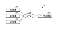
- FIG. 17 is a diagram showing a configuration of the system according to the third embodiment.
- FIG. 18 is a functional block diagram showing the configuration of the data processing apparatus according to the third embodiment.
- FIG. 19 is a diagram showing an example of visualization of conversation content on the office UI.
- FIG. 20 is a flowchart showing a processing procedure of the data processing apparatus according to the third embodiment.
- FIG. 21 is a diagram showing a configuration of the system according to the fourth embodiment.
- FIG. 22 is a functional block diagram showing the configuration of the data processing apparatus according to the fourth embodiment.
- FIG. 23 is a diagram for explaining the processing of the display unit according to the fourth embodiment.
- FIG. 24 is a flowchart showing a processing procedure of the data processing apparatus according to the fourth embodiment.
- FIG. 25 is a diagram showing an example of a computer that executes a data processing program.
- FIG. 1 is a diagram showing a configuration of a system according to the first embodiment. As shown in FIG. 1, this system 1A includes terminal devices 10a, 10b, 10c and a data processing device 100. In the system 1A, the terminal devices 10a to 10c and the data processing device 100 are shown, but the system 1A may further have another terminal device and another data terminal device.
- the terminal devices 10a to 10c and other terminal devices are collectively referred to as the terminal device 10 unless otherwise specified.
- the data processing device 100 does not have to be a device physically different from the terminal device 10, and may be a part of the terminal device 10. Further, the functional unit in the data processing device 100 does not have to be physically in the same device, and in particular, a part thereof may be arranged as a part of the terminal device 10.
- the terminal device 10 and the data processing device 100 are connected to each other via the network 2.
- the terminal device 10 is a terminal device used by the user to execute communication, and corresponds to a smartphone, a tablet terminal, a notebook PC (Personal Computer), or the like.
- the terminal device 10 executes data communication with the data processing device 100 and another terminal device 10 for which a call has been established via the network 2.
- the data processing device 100 creates spatial information simulating an office environment having a plurality of rooms, and based on instruction information received from each terminal device 10 used by the plurality of users, a plurality of users in the plurality of rooms. Display spatial information (office UI ⁇ User Interface>) with multiple icons corresponding to.
- the data processing device 100 connects a plurality of terminal devices corresponding to the plurality of icons displayed in the same room to each room in which the plurality of icons are displayed in the office UI to establish a call.
- the terminal device 10a and the terminal device 10b Establish a call.
- the data processing device 100 displays the office UI in which the icons corresponding to a plurality of users are arranged, so that the users who are actually separated from each other virtually provide the same space in which they exist together. can do.
- a call is established based on the icons arranged in the same room, it is possible to perform realistic communication simulating an environment in which a plurality of users work in the same office.
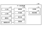
- FIG. 2 is a functional block diagram showing the configuration of the data processing apparatus according to the first embodiment.
- the data processing device 100 includes an input unit 110, an output unit 120, a communication unit 130, an information acquisition unit 140, a storage unit 150, and a control unit 160.
- the input unit 110 is an input interface that receives various operations from the operator of the data processing device 100.
- it is composed of an input device such as a keyboard and a mouse.
- the output unit 120 is an output device that outputs information acquired from the control unit 160, and is realized by a display device such as a liquid crystal display, a printing device such as a printer, or the like.
- the communication unit 130 is a communication interface for transmitting and receiving various information between the terminal device 10 and other devices connected via the network 1 and the like.
- the communication unit 130 is realized by a NIC (Network Interface Card) or the like, and communicates between the terminal device 10 and other devices and the control unit 160 via a telecommunication line such as a LAN (Local Area Network) or the Internet. ..
- the communication unit 130 receives information on the operation performed by the user on the terminal device 10 and information on the user's status via the network, and outputs the information to the control unit 160.
- the information acquisition unit 140 acquires video information taken by the camera of the terminal device 10 and audio information picked up by the microphone of the terminal device 10 from the terminal device 10 and outputs the information to the control unit 160.
- the storage unit 150 is realized by a semiconductor memory element such as a RAM (Random Access Memory) or a flash memory (Flash Memory), or a storage device such as a hard disk or an optical disk. In the first embodiment, the storage unit 150 stores the spatial information 151.
- a semiconductor memory element such as a RAM (Random Access Memory) or a flash memory (Flash Memory), or a storage device such as a hard disk or an optical disk.
- the storage unit 150 stores the spatial information 151.
- the spatial information 151 is information related to the office UI created by the creation unit 161 that receives the input operation of the administrator of the data processing device 100, and is the number and size of office rooms, chairs, desks, etc. arranged in the rooms. Information (positional relationship, etc.) is included. Further, as will be described later, various functions are set in the room, desk, and chair.
- the spatial information 151 may hold information about a plurality of types of office UIs. The information of each office UI is identified by an office ID or the like.
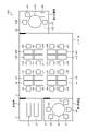
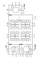
- FIG. 3 is a diagram showing an example of an office UI.
- the office UI 151a includes rooms r1, r2, r3, and r4, and desks and chairs are arranged in each of the rooms r1 to r4.
- room r1 corresponds to a break room.
- Chairs c1 and c2 are arranged in room r1.
- Room r2 corresponds to the first conference room.
- chairs c3, c4, c5, c6, c7 and a desk d1 are arranged.
- Room r3 corresponds to the office.
- chairs c8, c9, c10, c11, c12, c13, c14, c15, c16, c17, c18, c19, c20, c21, c22, c23 are arranged.
- desks d2, d3, d4, d5, d6, d7, d8, d9, d10, d11, d12, d13, d14, d15, d16, d17 are arranged.
- Room r4 corresponds to the second conference room.
- chairs c24, c25, c26, 27, c28 and a desk d18 are arranged.
- rooms r1 to r4 included in the office UI 151a are referred to as “rooms”.
- Chairs c1 to c28 are referred to as “chairs”.
- Desks d1 to d18 are referred to as “desks”.
- the control unit 160 is realized by using a CPU (Central Processing Unit) or the like, and executes a processing program stored in a memory. As a result, the control unit 160 functions as a creation unit 161, a display unit 162, and a call unit 163.
- a CPU Central Processing Unit
- the control unit 160 functions as a creation unit 161, a display unit 162, and a call unit 163.
- the creation unit 161 executes a process of creating spatial information 151. For example, the creation unit 161 creates the spatial information 151 based on the input information of the administrator who operates the input unit 110.
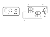
- FIG. 4 and 5 are diagrams for explaining the processing of the creating unit.
- the administrator uses the input unit 110 to perform a click operation and a drag operation with the pointer p1 to indicate the size of the office room.
- the creating unit 161 generates the rooms r2, r3, and r4 based on the instruction via the input unit 110.
- FIG. 5 will be described.
- the administrator uses the input unit 110 to perform a drag-and-drop operation with the pointer p1 to arrange a chair and a desk in the office room.
- the creation unit 161 displays the chair and desk icons on the display (output unit 120), and the administrator uses the input unit 110 to drag the chair and desk icons to the chair and desk icons. Perform an and drop operation.
- the creation unit 161 assigns functions and roles to rooms and objects based on the input from the administrator who operates the input unit 110. For example, the creation unit 161 gives each room a role such as a conference room and a break room. By giving these roles, the current situation of the user can be easily determined according to the room in which the user's icon is arranged.
- the creation unit 161 grants a function to lock each room and allow entry. This makes it possible to prevent information leakage.
- the creation unit 161 assigns one or a plurality of users to the desks arranged in the room, and imparts a function of setting a fixed position of the users. This makes it possible to easily determine whether each user is out of the office such as absenteeism or absenteeism.
- Creation unit 161 may create a temporary room. As a result, it is possible to temporarily create a pseudo-meeting room that does not exist in an actual office, and to cope with a shortage of meeting rooms.
- the creation unit 161 creates the spatial information 151 based on the input information of the administrator who operates the input unit 110, and stores the spatial information 151 in the storage unit 150.
- the creation unit 161 may automatically create the spatial information 151 based on the layout information and the image information of the actual office. For example, the creation unit 161 uses object detection technology to read information (positional relations, etc.) on the size, number, and arranged objects (desks, chairs) of office rooms from office layout information and image information. .. The creation unit 161 creates spatial information 151 based on the read office information.
- the creating unit 161 may generate the spatial information 151 by using the trained generation model.
- the administrator uses the input unit 110 to input characteristic information such as the number of office rooms and the number of objects.
- the creation unit 161 inputs the input feature information to the generative model, and obtains an output result (spatial information 151) from the generative model.
- the generative model corresponds to GAN (Generative Adversarial Network) and the like.
- the display unit 162 generates the office UI 151a described with reference to FIG. 3 based on the spatial information 151, and transmits the information of the office UI 151a to the terminal device 10 for display.
- the user of the terminal device 10 refers to the office UI 151a displayed on the terminal device 10 and operates the terminal device 10 to indicate his / her position.
- the terminal device 10 transmits the instruction information instructed by the user to the data processing device 100.
- the instruction information includes identification information that identifies the terminal device and the user, and location information of the user in the office UI 151a.
- the display unit 162 When the display unit 162 receives the instruction information from the terminal device 10, the display unit 162 arranges the icon corresponding to the user on the office UI 151a based on the instruction information, and transfers the information of the office UI 151a on which the icon is arranged to the terminal device 10. Send and display. The display unit 162 updates the office UI 151a and the icon in real time based on the instruction information transmitted from the terminal device 10.
- the user of the terminal device 10 moves the icon representing himself / herself to a desired position on the office UI 151a by a click operation or the like.
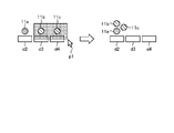
- 6 and 7 are diagrams for explaining an example of the movement of the icon.
- FIG. 6 will be described.
- the icon corresponding to the user A of the terminal device 10a is referred to as the icon 11a
- the icon corresponding to the user B of the terminal device 10b is referred to as the icon 11b.
- the user A performs a click operation on the desk d4 by using the terminal device 10a.
- the display unit 162 receives the instruction information regarding the click operation from the terminal device 10a, the display unit 162 shifts the icon 11a to the desk d4.
- FIG. 7 will be described.
- the icon corresponding to the user A of the terminal device 10a is the icon 11a
- the icon corresponding to the user B of the terminal device 10b is the icon 11b
- the icon corresponding to the user C of the terminal device 10c is the icon 11c.
- the user A performs a drag-and-drop operation on the icons 11b and 11c by using the terminal device 10a.
- the display unit 162 receives the instruction information regarding the drag-and-drop operation from the terminal device 10a, the display unit 162 shifts the icons 11b and 11c to the desk d2.
- the display unit 162 outputs the information regarding the position of the user's icon on the office UI 151a to the call unit 163 while executing the above processing according to the instruction information from the terminal device 10. For example, it is assumed that the icon is associated with the identification information of the user and the terminal device.
- the call unit 163 identifies a set of terminal devices 10 for establishing a call based on the information acquired from the display unit 162, and establishes a call between the specified terminal devices 10. For example, the call unit 163 scans each room, identifies a room in which a plurality of icons are arranged, and launches a call for each room in which the plurality of icons are arranged.
- FIG. 8 is a diagram for explaining the processing of the call unit according to the first embodiment.
- the icons 11a and 11b are arranged in the room r1.
- the icon 11d is arranged in the room r2.
- the icon 11c is arranged in the room r3.
- the user of the icon 11a is the user of the terminal device 10a.
- the user of the icon 11b is defined as the user of the terminal device 10b.
- the user of the icon 11c is defined as the user of the terminal device 10c.
- the user of the icon 11d is the user of the terminal device 10d.
- the user of the icon 11e is defined as the user of the terminal device 10e. In FIG. 1, the terminal devices 10d and 10e are not shown.
- the call unit 163 since the call unit 163 has a plurality of icons 11a and 11b arranged in the room r1, a call between the terminal device 10a and the terminal device 10b is established.
- the call unit 163 transmits video information and audio information acquired from the terminal device 10a to the terminal device 10b, and transmits video information and audio information acquired from the terminal device 10b to the terminal device 10a to make a call. To establish.
- the call unit 163 Since the call unit 163 has a plurality of icons 11d and 11e arranged in the room r2, the call unit 163 establishes a call between the terminal device 10d and the terminal device 10e. For example, the call unit 163 transmits video information and audio information acquired from the terminal device 10d to the terminal device 10e, and transmits video information and audio information acquired from the terminal device 10e to the terminal device 10d to make a call. To establish.
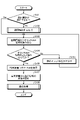
- FIG. 9 is a flowchart showing a processing procedure of the data processing apparatus according to the first embodiment.
- step S101 when the spatial information 151 exists (step S101, Yes), the data processing apparatus 100 shifts to step S103.
- step S101, No when the spatial information 151 does not exist (step S101, No), the data processing apparatus 100 shifts to step S102.
- the creation unit 161 of the data processing device 100 executes the spatial information creation process (step S102).
- the display unit 162 of the data processing device 100 reads the office UI information from the spatial information 151 (step S103). If the information in the office UI is not correctly read (step S104, No), the display unit 162 accepts another office ID (step S105) and proceeds to step S103.
- step S104 When the display unit 162 correctly reads the office UI information (steps S104, Yes), the display unit 162 proceeds to step S106.
- the display unit 162 causes the terminal device 10 to display the office UI (step S106).
- the display unit 162 starts receiving the instruction information of the instruction information from the terminal device 10 (step S107).
- the call unit 163 of the data processing device 100 executes call processing (step S108).
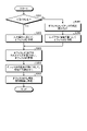
- FIG. 10 is a flowchart showing a processing procedure of the spatial information creation process.
- the creation unit 161 of the data processing device 100 creates an office UI in response to an input operation input from the input unit 110 (step S201, Yes).
- Step S202 the process proceeds to step S205.
- step S201 if the creation unit 161 is not created manually (step S201, No), the office layout information (or image information) is read (step S203). The creation unit 161 creates an office UI based on the layout information (step S204), and proceeds to step S205.
- the creation unit 161 accepts customization for the office UI and updates the office UI (step S205).
- the customization received by the creation unit 161 in step S206 corresponds to the arrangement or deletion of a room or an object (desk, chair, etc.).
- Creation unit 161 assigns functions and roles to office UI rooms and objects (step S206).
- the creation unit 161 registers the office UI information in the spatial information 151 (step S207).
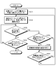
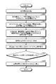
- FIG. 11 is a flowchart showing a processing procedure of call processing.
- the call unit 163 of the data processing device 100 launches a call in a room in which a plurality of icons are arranged (step S301).
- the call unit 163 establishes a call for each terminal device according to the room in which the plurality of icons are arranged (step S302).
- the call unit 163 proceeds to step S305 (steps S303, Yes). If the icon has not moved to another room on the office UI (steps S303, No), the call unit 163 proceeds to step S304.
- the call unit 163 ends the call process when the icon arranged on the office UI disappears (step S304, Yes). If the icon arranged in the office UI has not disappeared (step S304, No), the call unit 163 proceeds to step S303.
- step S305, Yes If there are a plurality of icons in the room before the movement (steps S305, Yes), the call unit 163 shifts to step S307. On the other hand, if the call unit 163 does not have a plurality of icons in the room before the move (step S305, No), the call unit 163 ends the call in the room before the move (step S306) and proceeds to step S307.
- step S307 When the call is set up in the room after the movement (step S307, Yes), the call unit 163 shifts to step S302. On the other hand, when the call is not started in the room after the movement (step S307, No), the call unit 163 shifts to step S301.
- the data processing device 100 creates spatial information 151 that imitates an office environment having a plurality of rooms, and based on instruction information received from each terminal device 10 used by the plurality of users, a plurality of rooms are in a plurality of rooms. Display the office UI with multiple icons corresponding to the user. Then, the data processing device 100 connects a plurality of terminal devices 10 corresponding to the plurality of icons displayed in the same room to each room in which the plurality of icons are displayed in the office UI to establish a call.
- the data processing device 100 displays the office UI in which the icons corresponding to the plurality of users are arranged, so that the users who are actually separated from each other virtually provide the same space in which they exist together. be able to.
- a call is established based on the icons arranged in the same room, it is possible to perform realistic communication simulating an environment in which a plurality of users work in the same office.
- the data processing device 100 simply expresses the office space using the office UI, it is possible to realize a space in which the existence of others can be recognized and the space is not too conscious. This makes it possible to improve concentration while creating a sense of unity that everyone is working together.
- FIG. 12 is a diagram showing a configuration of the system according to the second embodiment.
- this system 1B includes terminal devices 10a, 10b, 10c and a data processing device 200.
- the terminal devices 10a to 10c and the data processing device 200 are shown, but the system 1B may further have another terminal device and another data terminal device.
- terminal devices 10a to 10c The description of the terminal devices 10a to 10c is the same as the description of the first embodiment. Unless otherwise specified, the terminal devices 10a to 10c and other terminal devices are collectively referred to as the terminal device 10.
- the terminal device 10 and the data processing device 100 are connected to each other via the network 2.
- the data processing device 200 acquires user information using a device such as a camera or a microphone provided in the terminal device 10 and identifies the current state of the user. By displaying the state of the specified user on the office UI and reflecting it in real time, the data processing device 200 can provide the user with information equivalent to that of a real office in a virtual space called the office UI.
- FIG. 13 is a functional block diagram showing the configuration of the data processing device according to the second embodiment.
- the data processing device 200 includes an input unit 210, an output unit 220, a communication unit 230, an information acquisition unit 240, a storage unit 250, and a control unit 260.
- the description of the input unit 210, the output unit 220, and the communication unit 230 is the same as the description of the input unit 110, the output unit 120, and the communication unit 130 described in the first embodiment.
- the information acquisition unit 240 acquires video information taken by the camera of the terminal device 10 and audio information picked up by the microphone of the terminal device 10 from the terminal device 10. Further, the information acquisition unit 240 further acquires information on the operation status of the terminal device 10 by the user from the terminal device 10. The information acquisition unit 240 outputs video information, audio information, and operation status information to the control unit 260. It is assumed that the video information, the audio information, and the operation status information are given identification information for identifying the terminal device and the user.
- the storage unit 250 is realized by a semiconductor memory element such as RAM or flash memory, or a storage device such as a hard disk or an optical disk. In the second embodiment, the storage unit 250 stores the spatial information 251.
- the description of the spatial information 251 is the same as the description of the spatial information 151 described in the first embodiment.
- the office UI 151a described with reference to FIG. 3 is displayed based on the spatial information 251.
- the control unit 260 is realized by using a CPU or the like and executes a processing program stored in a memory. As a result, the control unit 260 functions as a creation unit 261, an analysis unit 262, a display unit 263, and a call unit 264.
- the creation unit 261 executes a process of creating spatial information 251. For example, the creation unit 261 creates the spatial information 251 based on the input information of the administrator who operates the input unit 210. Other explanations regarding the preparation unit 261 are the same as those of the preparation unit 161 of the first embodiment.
- the analysis unit 262 analyzes the user's situation based on the video information, the audio information, and the operation status information received from the terminal device 10, and shifts to some states (while present, away from the seat, talking, etc.). Classify as. For example, the analysis unit 262 uses image recognition technology to identify in real time whether the user is present or absent from the video information. The analysis unit 262 uses voice recognition technology to identify in real time during a call, a meeting, a conversation, etc. from voice information. The analysis unit 262 identifies whether or not the user is engaged in business based on the information on the operation status.
- the analysis unit 262 classifies the user's situation into several states by performing the above analysis with respect to the user who is in the office, and also from the user's terminal device 10 to the user's current position. Get information.
- the analysis unit 262 is a pedometer of the terminal device 10, a link state of wireless communication installed between the terminal device 10 and the office desk (Wifi, Bluetooth, other wireless devices, etc.), the strength of radio waves, and the quality of signals and links. Etc.), it is determined whether or not the user is in the office, and when the user is in the office, the moving position of the user is estimated and the current position of the user is specified.
- the user may wear a sensor that can specify the position by video, radio waves, or the like, and the analysis unit 262 may acquire information from the sensor to specify the user's current position.
- the analysis unit 262 further identifies not only the user of the terminal device 10 but also the states of other users based on the video information and the audio information transmitted from the terminal device 10. You may. For example, the analysis unit 262 can acquire the user's state more accurately by specifying the user's state and the current position with respect to another user included in the video information.
- the process of identifying the user's state by the analysis unit 262 described above is an example, and the user's state may be specified by another technique.
- the analysis unit 262 outputs the user status information in which the user status and the identification information are associated with the user who is not in the office to the display unit 263.
- the analysis unit 262 outputs the user state information in which the user's state, the user's current position, and the identification information are associated with each other to the display unit 263 for the user who is in the office.
- the display unit 263 When the display unit 263 receives the instruction information from the terminal device 10 in the same manner as the display unit 162 described in the first embodiment, the display unit 263 displays an icon corresponding to the user (telework user) based on the instruction information in the office UI 151a. Place on top. Further, the display unit 263 arranges the icon of the user (the user who is in the office) on the office UI 151a based on the current position included in the user status information. The display unit 263 transmits the information of the office UI 151a in which the icon is arranged to the terminal device 10 to display the information.
- the display unit 263 displays the user status by the color and mark of the icon, blinking, movement, voice, etc., based on the user status information acquired from the analysis unit 262.
- FIG. 14 is a diagram showing an example of an icon representing the state of the user. Here, the description will be given using the icon 11a of the user A of the terminal device 10a.
- the display unit 263 changes the color of the frame 12 of the icon 11a based on the state of the user A. For example, when the user A is present, the color of the frame 12 is displayed in the first color, when the user A is away, the color is displayed in the second color, and when the user is in a conversation. Is displayed in the third color.
- the display unit 263 assigns the mark 13 to the icon 11a based on whether or not the user A is in the office. For example, the display unit 263 adds the mark 13 when the user A is at work.
- the display unit 263 classifies the user into an attendance group and a telework group according to the attendance status of the user of each icon arranged on the office UI 151a, and assigns a mark 13 when the user A belongs to the minority group. You may.
- the display unit 263 may display the user's name, image, illustration, etc. in the icon 11a. It is assumed that the user's name, image, illustration, etc. are stored in the storage unit 250 in association with the identification information.
- FIG. 15 is a diagram for explaining the processing of the display unit according to the second embodiment.
- icons 11a to 11q are arranged on the office UI 151b.
- the icons 11a, 11b, 11c, 11d, 11h, 11i, 11k, and 11m indicate that the user corresponding to the icon is present because the color of the frame is the first color. Since the color of the frame of the icons 11l, 11p, and 11q is the second color, it indicates that the user corresponding to the icon is away from the desk. Since the color of the frame of the icons 11e, 11f, 11g, 11j, 11n, and 11p is the third color, it indicates that the user corresponding to the icon is away from the desk.
- the display unit 263 assigns marks to the icons 11a, 11g, 11h, 11i, 11l, 11n, and 11p. For example, if the user of the icon 11a is teleworking, it means that the user of each icon 11a, 11g, 11h, 11i, 11l, 11n, 11p to which the mark is given is teleworking.
- the display unit 263 may display the attendance and absence of the user in a distinguishable manner by changing the color of the chair. Further, the display unit 263 may indicate that the room is in use by highlighting the color of the room.
- the display unit 263 outputs the information regarding the position of the user's icon on the office UI 151b to the call unit 264 while executing the above processing according to the instruction information from the terminal device 10. For example, it is assumed that the icon is associated with the identification information of the user and the terminal device.
- the call unit 264 identifies a set of terminal devices 10 for establishing a call based on the information acquired from the display unit 263, and establishes a call between the specified terminal devices 10. For example, the call unit 264 scans each room, identifies a room in which a plurality of icons are arranged, and launches a call for each room in which the plurality of icons are arranged.
- the other description of the call unit 264 is the same as the description of the call unit 163 described in the first embodiment.
- FIG. 16 is a flowchart showing a processing procedure of the analysis unit according to the second embodiment.
- the analysis unit 262 of the data processing device 200 acquires video information, audio information, and operation status information from the terminal device 10 via the information acquisition unit 240 (step S401).
- the analysis unit 262 analyzes the user's state based on the video information, the audio information, and the operation status information (step S402). If the user's state cannot be specified (step S403, No), the analysis unit 262 ends the process.
- step S403 determines whether or not the user exists in the office (step S404). If the user does not exist in the office (steps S404, No), the analysis unit 262 proceeds to step S406.
- the analysis unit 262 identifies the current position of the user from the information of the terminal device 10 obtained via the information acquisition unit 240 (step S405). .. The analysis unit 262 outputs the user status information to the display unit 263 (step S406).
- the analysis unit 262 may fix the user's current position to a fixed position set for each user when the user is not in the office. Further, the analysis unit 262 may be fixed at a position on the office UI of a place where the user may perform business, assuming an actual office such as in front of a desk to which the user is not assigned. The user may specify the current position on the office UI in the same manner as in the first embodiment.
- the display unit 263 displays the office UI based on the user status information, but does not reflect the user's current position except for the movement by the user's operation, the movement in the meeting, and the conversation, and the user. Only the state of may be reflected in the icon.
- the display unit 263 may estimate the location corresponding to the case of being in the office from the information specified by the analysis unit 262 and reflect it on the office UI.
- the data processing device 200 acquires video information, audio information, and operation status information from the terminal device 10, identifies the user's state, and displays an icon with a color, a mark, or the like corresponding to the specified state. Also, the current position of the user is estimated and placed on the office UI. As a result, the user can easily grasp the state and the current position of another user on the office UI.
- information such as the position and state of another person, which can be acquired in the real space, can be acquired in the virtual space as well.
- the stress of the user can be reduced by not displaying the image of the user himself or the image of the user's home.
- FIG. 17 is a diagram showing a configuration of the system according to the third embodiment.
- this system 1C includes terminal devices 10a, 10b, 10c and a data processing device 300.
- the terminal devices 10a to 10c and the data processing device 300 are shown, but the system 1C may further have another terminal device and another data terminal device.
- terminal devices 10a to 10c The description of the terminal devices 10a to 10c is the same as the description of the first embodiment. Unless otherwise specified, the terminal devices 10a to 10c and other terminal devices are collectively referred to as the terminal device 10.
- the terminal device 10 and the data processing device 300 are connected to each other via the network 2.
- the data processing device 300 analyzes voice information in addition to the processing of the data processing device 200 of the second embodiment, and enhances communication in the virtual space by truncating and visualizing the information based on the analyzed voice content. Allows you to.
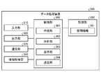
- FIG. 18 is a functional block diagram showing the configuration of the data processing device according to the third embodiment.
- the data processing device 300 includes an input unit 310, an output unit 320, a communication unit 330, an information acquisition unit 340, a storage unit 350, and a control unit 360.
- the description of the input unit 310, the output unit 320, and the communication unit 330 is the same as the description of the input unit 110, the output unit 120, and the communication unit 130 described in the first embodiment.
- the information acquisition unit 340 acquires video information taken by the camera of the terminal device 10 and audio information picked up by the microphone of the terminal device 10 from the terminal device 10. Further, the information acquisition unit 340 further acquires information on the operation status of the terminal device 10 by the user from the terminal device 10. The information acquisition unit 340 outputs video information, audio information, and operation status information to the control unit 360. It is assumed that the video information, the audio information, and the operation status information are given identification information for identifying the terminal device and the user.
- the storage unit 350 is realized by a semiconductor memory element such as RAM or flash memory, or a storage device such as a hard disk or an optical disk. In the third embodiment, the storage unit 350 stores the spatial information 251.
- the description of the spatial information 351 is the same as the description of the spatial information 151 described in the first embodiment.
- the office UIs 151a and 151b described with reference to FIGS. 3 and 15 are displayed based on the spatial information 351.
- the control unit 360 is realized by using a CPU or the like and executes a processing program stored in a memory. As a result, the control unit 360 functions as a creation unit 361, an analysis unit 362, a display unit 363, and a call unit 364.
- the creation unit 361 executes a process of creating spatial information 351. For example, the creation unit 361 creates spatial information 351 based on the input information of the administrator who operates the input unit 310. Other explanations regarding the preparation unit 361 are the same as those of the preparation unit 161 of the first embodiment.
- the analysis unit 362 analyzes the contents of utterances and conversations using voice and conversation analysis technology for the voice information acquired by the information acquisition unit 240.
- the analysis unit 362 identifies utterances, conversation contents, and extracts characteristic words based on the analysis results of utterances and conversations. Further, the analysis unit 362 determines whether or not to convey to another user from the specified utterances and conversation contents. For example, the analysis unit 362 determines that when the utterance content is a soliloquy, a telephone call with a person outside the company, a conversation with a person unrelated to the business, or the like, the voice is not transmitted to surrounding users. Further, when the conversation by a plurality of users is the content of the business related to only a part of the users, the analysis unit 362 determines that the voice is transmitted only to the users involved in the business.
- the analysis unit 362 determines whether or not to convey to other users from the utterances and conversation contents based on the table that defines the utterances and conversation contents that are not transmitted to other users.
- the analysis unit 362 uses a table that defines the user's identification information, the relationship with the department to which the user belongs, and the content of the utterance peculiar to the department, and identifies the voice that is not transmitted to anyone other than the user involved in the business.
- the analysis unit 362 outputs the content of the analyzed voice information and the determination result (determination result of whether or not to convey to another user) to the display unit 363 and the call unit 364. Although the description is omitted, the analysis unit 362 identifies the user's state based on the information of the video information, the audio information, and the operation information in the same manner as the analysis unit 262 of the second embodiment, and outputs the user's state to the display unit 363. You may.
- the display unit 363 adjusts the position of the icon on the office UI based on the content of the voice information acquired from the analysis unit 362 and the determination result. For example, when the voice information received from the terminal device 10 is a conversation about a business involving only some users, the display unit 363 moves the position of the icon of the user during the conversation to another room. Let me. As a result, the rooms are separated, so that the voice is not heard by users who are not related to business conversations (the call unit 364 described later makes a call between terminal devices corresponding to the icons in the same room. To establish).
- the display unit 363 automatically generates a temporary room when the icon of the user who is talking about another business is arranged in the room to which the user's icon is moved and the remaining room does not exist. Then move the user's icon to that room. Further, when only a part of the users in conversation are using the conference room or the like in the actual office, the display unit 363 may move the other users to the automatically generated room.
- the display unit 363 When the user who is having a conversation is actually in the office, the display unit 363 temporarily ignores the user's actual position and moves the current position on the office UI. You may return the icon to the actual current position.
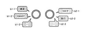
- FIG. 19 is a diagram showing an example of visualization of conversation content on the office UI. As shown in FIG. 19, the content of the conversation is shown by a balloon or the like near the user in the conversation.
- the display unit 363 displays the topic genre (topic related to business, topic related to general news) and the like in a distinguishable manner according to the color and shape of the balloon.
- the display unit 363 expresses the characteristic words in the conversation by the words in the balloon.
- balloons b1-1, b1-2, and b-3 are balloons related to business
- balloons b2-1, b2-2, and b2-3 are balloons related to characteristic words.
- the display unit 353 does not display all the voice information as a balloon, but displays only the topics related to business, the topics related to news, and the characteristic words, so that the discomfort related to listening to the conversation can be reduced. Will be possible.
- the display unit 363 may visually reflect the user's state on the icon in the same manner as the display unit 263 of the second embodiment.
- the call unit 364 identifies a set of terminal devices 10 for establishing a call based on the information acquired from the display unit 363, and establishes a call between the specified terminal devices 10. For example, the call unit 364 scans each room, identifies a room in which a plurality of icons are arranged, and launches a call for each room in which the plurality of icons are arranged.
- the call unit 364 controls the transmission / reception of voice information between the terminal devices based on the information acquired from the analysis unit 362. For example, in the case where a call is established with the terminal devices 10a and 10b, while the voice information of the terminal device 10a is determined to be voice information that is not transmitted to other users, the call unit 364 uses the terminal device 364. The transmission of voice information from 10a to the terminal device 10b is temporarily stopped. After that, when the voice information of the terminal device 10a is determined to be the voice information to be transmitted to another user, the call unit 364 resumes the transmission of the voice information.
- FIG. 20 is a flowchart showing a processing procedure of the data processing apparatus according to the third embodiment.
- the analysis unit 362 of the data processing device 300 acquires voice information (step S501).
- the analysis unit 362 analyzes the voice information (step S502). If the acquired voice information is voice information to be transmitted to surrounding users (steps S503 and Yes), the analysis unit 362 shifts to step S504. On the other hand, if the analysis unit 362 is not voice information to be transmitted to surrounding users (steps S503 and No), the analysis unit 362 shifts to step S506.
- the analysis unit 362 ends the process when the conversation content and the characteristic word cannot be extracted (steps S504 and No). On the other hand, the analysis unit 362 shifts to step S505 when the conversation content and characteristic words can be extracted (steps S504 and Yes).
- the display unit 363 of the data processing device 300 displays a balloon on the icon (step S505).
- the display unit 363 moves the position of the icon so that it cannot be heard by surrounding users (step S506).
- the data processing device 300 analyzes voice information, determines whether or not the information is necessary for other users, and adjusts so that the voice information determined to be unnecessary is not transmitted, thereby eliminating factors that hinder concentration. Can be done.
- the data processing device 300 analyzes voice information and extracts information such as conversation contents and characteristic words. Then, by visualizing this information on the office UI, it is possible to acquire information about the conversation being held at a place away from the user. This makes it easier to enter into conversations that are taking place at remote locations and increases communication opportunities.
- FIG. 21 is a diagram showing a configuration of the system according to the fourth embodiment.
- this system 1D includes terminal devices 10a, 10b, 10c and a data processing device 400.
- the terminal devices 10a to 10c and the data processing device 400 are shown, but the system 1D may further have another terminal device and another data terminal device.
- terminal devices 10a to 10c The description of the terminal devices 10a to 10c is the same as the description of the first embodiment. Unless otherwise specified, the terminal devices 10a to 10c and other terminal devices are collectively referred to as the terminal device 10.
- the terminal device 10 and the data processing device 400 are connected to each other via the network 2.
- the data processing device 400 realizes a realistic conversation environment in a virtual space by adjusting how the voice is heard during a call based on the distance between the icons on the office UI and the volume of the speaker. .. Further, the data processing device 400 makes it possible to provide a more comfortable conversation environment by visualizing the voice environment at the time of a call on the office UI.
- FIG. 22 is a functional block diagram showing the configuration of the data processing device according to the fourth embodiment.
- the data processing device 400 includes an input unit 410, an output unit 420, a communication unit 430, an information acquisition unit 440, a storage unit 450, and a control unit 460.
- the description of the input unit 410, the output unit 420, and the communication unit 430 is the same as the description of the input unit 110, the output unit 120, and the communication unit 130 described in the first embodiment.
- the information acquisition unit 440 acquires video information taken by the camera of the terminal device 10 and audio information picked up by the microphone of the terminal device 10 from the terminal device 10. Further, the information acquisition unit 440 further acquires information on the operation status of the terminal device 10 by the user from the terminal device 10. The information acquisition unit 440 outputs video information, audio information, and operation status information to the control unit 460. It is assumed that the video information, the audio information, and the operation status information are given identification information for identifying the terminal device and the user.
- the storage unit 450 is realized by a semiconductor memory element such as RAM or flash memory, or a storage device such as a hard disk or an optical disk. In the fourth embodiment, the storage unit 450 stores the spatial information 451 and the user voice information 452.
- the description of the spatial information 451 is the same as the description of the spatial information 151 described in the first embodiment.
- the office UIs 151a and 151b described with reference to FIGS. 3 and 15 are displayed based on the spatial information 451.
- the user voice information 452 includes pre-registered volume of each user during normal conversation, information of attributes given according to the business content of the user, and the like. For example, the user voice information 452 associates the volume during conversation with the attribute with respect to the identification information of each user.
- the attributes correspond to the department to which they belong.
- the control unit 460 is realized by using a CPU or the like and executes a processing program stored in the memory. As a result, the control unit 460 functions as a creation unit 461, an analysis unit 462, a display unit 463, and a call unit 464.
- the creation unit 461 executes a process of creating spatial information 451. For example, the creation unit 461 creates spatial information 451 based on the input information of the administrator who operates the input unit 410. Other explanations regarding the preparation unit 461 are the same as those of the preparation unit 161 of the first embodiment.
- the analysis unit 462 analyzes the contents of the utterance and conversation based on the voice information acquired by the information acquisition unit 440 and the user voice information 452. For example, the analysis unit 462 specifies the difference between the volume during normal conversation and the volume of voice information, and the attributes of each user. For example, the analysis unit 462 may analyze the closeness of each user's attributes based on a table that defines the closeness of one attribute to another.
- the analysis unit 462 outputs the analysis result to the display unit 463 and the call unit 464.
- the analysis results include the user's identification information, the difference between the volume during normal conversation and the volume of voice information, and the closeness of the user's attributes.
- the display unit 463 When the display unit 463 receives the instruction information from the terminal device 10 in the same manner as the display unit 162 described in the first embodiment, the display unit 463 displays an icon corresponding to the user (telework user) based on the instruction information in the office UI 151a. Place on top. Further, the display unit 463 may arrange an icon of a user (a user who is in the office) on the office UI 151a based on the current position included in the user status information. The display unit 463 transmits the information of the office UI 151a in which the icon is arranged to the terminal device 10 to display the information.
- the display unit 463 outputs the distance information between the icons on the office UI 151a to the call unit 464.
- the distance information includes the identification information of the target user and the information of the distance between the users.
- the call unit 464 adjusts the volume between the terminal devices for which a call has been established based on the analysis result acquired from the analysis unit 462 and the distance information acquired from the display unit 463.
- the call unit 464 when a call is established between the terminal device 10a of the user A and the terminal device 10b of the user B, the distance of the icon of the user A and the distance of the icon of the user B are separated (threshold). In the above case), control is performed to reduce the voice of the user A output from the terminal device 10b.
- the call unit controls to reduce the voice of the user B output from the terminal device 10a.
- the distance between the user A icon and the user B icon is less than the threshold value
- the distance between the user A icon and the user C icon is greater than or equal to the threshold value
- the user A voice information is lower than the volume of a normal conversation.
- the call unit 464 makes adjustments to reduce the range in which the user's voice can be heard. For example, in the call unit 464, when the icon of the user B is included in the adjusted range based on the position of the icon of the user A and the icon of the user C is not included, the volume of the voice information of the user A is included. Is output from the terminal device 10b of the user B while maintaining the normal volume, and the voice information of the user A is not output from the terminal device 10c of the user C.
- the call unit 464 is a terminal device.
- the voice of user A and the voice of user B output from 10 may be adjusted to the same volume. That is, the call unit 464 outputs the voice from the terminal device 10 at a constant volume regardless of the individual difference in the volume of the voice.
- the call unit 464 may adjust the volume or cut the voice according to the work related to the user. For example, assign attributes to the user according to the user's business content, turn down the volume a little if the attributes of other users who are having a conversation nearby are slightly different, and cut the voice if the attributes are significantly different. ..
- the call unit 464 may acquire information on the closeness of each user's attributes from the analysis unit 462, the combination of the user's attributes, and the control content of the call (lowering the volume, cutting the voice, etc.). You may control the call based on the table associated with.
- the call unit 464 outputs information about the voice received by the other party of the call to the analysis unit 462.
- the analysis unit 462 acquires information about the voice received by the other party of the call from the call unit 464, and based on the acquired information, the intelligibility, the degree of understanding, and the delay. Quality such as presence / absence is analyzed using voice quality evaluation technique and conversation analysis technique, and the analysis result is output to the display unit 463.
- FIG. 23 is a diagram for explaining the processing of the display unit according to the fourth embodiment.
- the display unit 463 draws concentric circles when the user is generated, and displays the audible range and size.
- FIG. 23 shows an icon 11a corresponding to the user A, an icon 11b corresponding to the user B, and an icon 11c corresponding to the user C.
- the range in which the user B is speaking and the voice information by the user B can be heard is indicated by the concentric circles 16b.
- the volume of the user B output from the terminal device 10b of the user A is indicated by the bar 15a
- the volume of the user B output from the terminal device 10c of the user C is indicated by the bar 15c. Since the distance between the icon 11b and the icon 11c is smaller than the distance between the icon 11b and the icon 11a, the display unit 463 displays the volume indicated by the bar 15c higher than the volume indicated by the bar 15a.
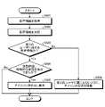
- FIG. 24 is a flowchart showing a processing procedure of the data processing apparatus according to the fourth embodiment.
- the analysis unit 462 of the data processing device 400 acquires voice information by using the information acquisition unit 440 (step S601).
- the analysis unit 462 compares and analyzes the voice information and the user voice information 452, and outputs the analysis result to the call unit 464 (step S602).
- the display unit 463 of the data processing device 400 compares the distance and attributes of each icon on the office UI, and outputs the distance information and the attribute information to the call unit 464 (step S603).
- the call unit 464 of the data processing device 400 adjusts the volume of the voice output from the terminal device that establishes the call based on the analysis result, the distance information, and the attribute information (step S604).
- the display unit 463 displays the utterance status on the office UI (step S605).
- the analysis unit 462 acquires information about how the other party of the call sounds from the call unit 464 (step S606). If the analysis unit 462 does not acquire the way the other party hears the call (step S607, No), the analysis unit 462 ends the process.
- step S607 When the analysis unit 462 acquires the way the other party hears the call (step S607, Yes), the analysis unit 462 proceeds to step S608.
- the display unit 463 displays how the voice is heard on the office UI (step S608).
- the data processing device 400 adjusts the range in which the voice can be heard and the loudness of the volume based on the positions of the users in the UI and the volume of the user's voice. This brings the conversation environment in the virtual space closer to the real conversation environment and realizes comfortable communication.
- the data processing device 400 registers normal voice and voice volume during normal conversation for each user. Based on the registered information, the data processing device 400 can make a call at a constant volume regardless of individual differences in volume and visualize the voice quality during conversation on the office UI. This will provide a comfortable conversation environment.
- FIG. 25 is a diagram showing an example of a computer that executes a data processing program.
- the computer 1000 has, for example, a memory 1010, a CPU 1020, a hard disk drive interface 1030, a disk drive interface 1040, a serial port interface 1050, a video adapter 1060, and a network interface 1070. Each of these parts is connected by a bus 1080.
- the memory 1010 includes a ROM (Read Only Memory) 1011 and a RAM 1012.
- the ROM 1011 stores, for example, a boot program such as a BIOS (Basic Input Output System).
- BIOS Basic Input Output System
- the hard disk drive interface 1030 is connected to the hard disk drive 1031.
- the disk drive interface 1040 is connected to the disk drive 1041.
- a removable storage medium such as a magnetic disk or an optical disk is inserted into the disk drive 1041.
- a mouse 1051 and a keyboard 1052 are connected to the serial port interface 1050.
- a display 1061 is connected to the video adapter 1060, for example.
- the hard disk drive 1031 stores, for example, the OS 1091, the application program 1092, the program module 1093, and the program data 1094. Each piece of information described in the above embodiment is stored in, for example, the hard disk drive 1031 or the memory 1010.
- the data processing program is stored in the hard disk drive 1031 as, for example, a program module 1093 in which a command executed by the computer 1000 is described.
- the program module 1093 in which each process executed by the data processing apparatus 100 (200, 300, 400) described in the above embodiment is described is stored in the hard disk drive 1031.
- the data used for information processing by the data processing program is stored as program data 1094 in, for example, the hard disk drive 1031.
- the CPU 1020 reads the program module 1093 and the program data 1094 stored in the hard disk drive 1031 into the RAM 1012 as needed, and executes each of the above-mentioned procedures.
- the program module 1093 and the program data 1094 related to the data processing program are not limited to the case where they are stored in the hard disk drive 1031. For example, they are stored in a removable storage medium and read by the CPU 1020 via the disk drive 1041 or the like. It may be issued. Alternatively, the program module 1093 and the program data 1094 related to the data processing program are stored in another computer connected via a network such as a LAN or WAN (Wide Area Network), and read by the CPU 1020 via the network interface 1070. May be done.
- a network such as a LAN or WAN (Wide Area Network)
- Data processing device 110 110,210,310,410 Input unit 120,220,320,420 Output unit 130,230,330,430 Communication unit 140,240,340,440 Information acquisition unit 150,250 , 350, 450 Storage unit 151,251,351,451 Spatial information 160,260,360,460 Control unit 161,261,361,461 Creation unit 162,263,363,463 Display unit 163,264,364,464 Calls Department 262,362,462 Analysis Department 452 User voice information
Landscapes
- Engineering & Computer Science (AREA)
- Theoretical Computer Science (AREA)
- General Engineering & Computer Science (AREA)
- Physics & Mathematics (AREA)
- General Physics & Mathematics (AREA)
- Human Computer Interaction (AREA)
- Multimedia (AREA)
- Signal Processing (AREA)
- Health & Medical Sciences (AREA)
- Audiology, Speech & Language Pathology (AREA)
- General Health & Medical Sciences (AREA)
- User Interface Of Digital Computer (AREA)
Abstract
Description
110,210,310,410 入力部
120,220,320,420 出力部
130,230,330,430 通信部
140,240,340,440 情報取得部
150,250,350,450 記憶部
151,251,351,451 空間情報
160,260,360,460 制御部
161,261,361,461 作成部
162,263,363,463 表示部
163,264,364,464 通話部
262,362,462 分析部
452 ユーザ音声情報
Claims (8)
- 複数の部屋を有するオフィス環境を模した空間情報を作成する作成部と
複数のユーザが利用する各端末装置からの指示情報を基にして、前記複数の部屋に、複数のユーザに対応する複数のアイコンを配置した空間情報を表示させる表示部と、
前記空間情報において複数のアイコンが表示された部屋毎に、同一の部屋に表示されている複数のアイコンに対応する複数の端末装置を接続して通話を確立させる通話部と
を備えることを特徴とするデータ処理装置。 - 前記ユーザの映像情報、前記ユーザの音声情報と、前記端末装置に対する操作状況の情報を含むユーザ情報を基にして、前記ユーザの状態を特定する分析部を更に備え、前記表示部は、前記ユーザ情報に対応するユーザのアイコンについて、前記ユーザの状態を視覚可能に表示することを特徴とする請求項1に記載のデータ処理装置。
- 前記分析部は、前記ユーザの音声情報を基にして、所定の会話内容に対応するか否かを分析し、前記表示部は、前記分析部の分析結果を基にして、前記アイコンの位置を調整することを特徴とする請求項2に記載のデータ処理装置。
- 前記表示部は、オフィスに存在するユーザの位置情報を取得し、取得した位置情報を基にして、前記オフィスに存在するユーザに対応するアイコンを、空間情報に配置することを特徴とする請求項1に記載のデータ処理装置。
- 前記通話部は、通話を確立させた複数の端末装置に対応する各ユーザのアイコン間の距離を基にして、各ユーザの音声の音量を調整する処理を更に実行することを特徴とする請求項1に記載のデータ処理装置。
- 前記表示部は、前記通話部による音量の調整結果を視覚可能に前記アイコンに表示させる処理を更に実行することを特徴とする請求項5に記載のデータ処理装置。
- 複数の部屋を有するオフィス環境を模した空間情報を作成する作成工程と
複数のユーザが利用する各端末装置からの指示情報を基にして、前記複数の部屋に、複数のユーザに対応する複数のアイコンを配置した空間情報を表示させる表示工程と、
前記空間情報において複数のアイコンが表示された部屋毎に、同一の部屋に表示されている複数のアイコンに対応する複数の端末装置を接続して通話を確立させる通話工程と
を含んだことを特徴とするデータ処理方法。 - コンピュータを請求項1~6に記載のデータ処理装置として機能させるためのデータ処理プログラム。
Priority Applications (3)
| Application Number | Priority Date | Filing Date | Title |
|---|---|---|---|
| JP2022564968A JP7533618B2 (ja) | 2020-11-27 | 2020-11-27 | データ処理装置、データ処理方法およびデータ処理プログラム |
| US18/038,946 US12500998B2 (en) | 2020-11-27 | 2020-11-27 | Data processing device, data processing method, and data processing program |
| PCT/JP2020/044380 WO2022113307A1 (ja) | 2020-11-27 | 2020-11-27 | データ処理装置、データ処理方法およびデータ処理プログラム |
Applications Claiming Priority (1)
| Application Number | Priority Date | Filing Date | Title |
|---|---|---|---|
| PCT/JP2020/044380 WO2022113307A1 (ja) | 2020-11-27 | 2020-11-27 | データ処理装置、データ処理方法およびデータ処理プログラム |
Publications (1)
| Publication Number | Publication Date |
|---|---|
| WO2022113307A1 true WO2022113307A1 (ja) | 2022-06-02 |
Family
ID=81755430
Family Applications (1)
| Application Number | Title | Priority Date | Filing Date |
|---|---|---|---|
| PCT/JP2020/044380 Ceased WO2022113307A1 (ja) | 2020-11-27 | 2020-11-27 | データ処理装置、データ処理方法およびデータ処理プログラム |
Country Status (3)
| Country | Link |
|---|---|
| US (1) | US12500998B2 (ja) |
| JP (1) | JP7533618B2 (ja) |
| WO (1) | WO2022113307A1 (ja) |
Cited By (1)
| Publication number | Priority date | Publication date | Assignee | Title |
|---|---|---|---|---|
| JP2024024879A (ja) * | 2022-08-10 | 2024-02-26 | シャープ株式会社 | 表示制御システム、表示制御方法、及び表示制御プログラム |
Families Citing this family (1)
| Publication number | Priority date | Publication date | Assignee | Title |
|---|---|---|---|---|
| JP2024010792A (ja) * | 2022-07-13 | 2024-01-25 | シャープ株式会社 | 音声制御システム、音声制御方法、及び音声制御プログラム |
Family Cites Families (2)
| Publication number | Priority date | Publication date | Assignee | Title |
|---|---|---|---|---|
| EP2954673A2 (en) * | 2013-02-07 | 2015-12-16 | Bansal, Sanjay | A graphical user interface (gui) for a conference call |
| JP6729193B2 (ja) * | 2016-08-31 | 2020-07-22 | 沖電気工業株式会社 | 情報処理サーバ、情報処理システム、端末装置、及びプログラム |
-
2020
- 2020-11-27 US US18/038,946 patent/US12500998B2/en active Active
- 2020-11-27 JP JP2022564968A patent/JP7533618B2/ja active Active
- 2020-11-27 WO PCT/JP2020/044380 patent/WO2022113307A1/ja not_active Ceased
Non-Patent Citations (4)
| Title |
|---|
| ANONYMOUS: "Zoom SpatialChat", 15 May 2020 (2020-05-15), pages 1 - 10, XP055941298, Retrieved from the Internet <URL:https://internet.watch.impress.co.jp/docs/review/1252198.html> [retrieved on 20220712] * |
| HIRATA, TOSHIYUKI ET AL.: "Development and Evaluation of Situation Information Sharing System Based on User's Permission-based Privacy", TRANSACTIONS OF INFORMATION PROCESSING SOCIETY OF JAPAN, vol. 48, no. 1, 15 January 2007 (2007-01-15), pages 189 - 199 * |
| MURAKAMI, MARIKO: "Part 3 A new way of work style next to telework, To the era of 'attendance' in virtual space", TELECOMMUNICATION JUNE 2020, vol. 37, no. 6, 25 May 2020 (2020-05-25), pages 16 - 19 * |
| YATSUNAMI, SHIHO: "Visualize presence with 'Remo' Eliminate loneliness in the remote work", WEB DESIGNING AUGUST 2020, vol. 20, no. 4, 23 June 2020 (2020-06-23), pages 50 - 53 * |
Cited By (2)
| Publication number | Priority date | Publication date | Assignee | Title |
|---|---|---|---|---|
| JP2024024879A (ja) * | 2022-08-10 | 2024-02-26 | シャープ株式会社 | 表示制御システム、表示制御方法、及び表示制御プログラム |
| JP7847058B2 (ja) | 2022-08-10 | 2026-04-16 | シャープ株式会社 | 表示制御システム、表示制御方法、及び表示制御プログラム |
Also Published As
| Publication number | Publication date |
|---|---|
| JP7533618B2 (ja) | 2024-08-14 |
| US12500998B2 (en) | 2025-12-16 |
| US20230421724A1 (en) | 2023-12-28 |
| JPWO2022113307A1 (ja) | 2022-06-02 |
Similar Documents
| Publication | Publication Date | Title |
|---|---|---|
| EP2962423B1 (en) | Controlling an electronic conference based on detection of intended versus unintended sound | |
| EP2016705B1 (en) | Managing conference call participants in a roster | |
| CN103534689B (zh) | 存在的展示或共享状态 | |
| US8744065B2 (en) | Method and system for monitoring contact center transactions | |
| US20040064322A1 (en) | Automatic consolidation of voice enabled multi-user meeting minutes | |
| WO2018183020A1 (en) | Headset with multiple microphone booms | |
| EP4248645A2 (en) | Spatial audio in video conference calls based on content type or participant role | |
| TW202119392A (zh) | 支援人機協作的即時簡訊機器人的系統及方法 | |
| JP2539153B2 (ja) | 仮想会議システム用端末装置及び仮想会議システム | |
| KR102178174B1 (ko) | 사용자 단말, 방송 장치, 이를 포함하는 방송 시스템 및 그 제어방법 | |
| JP7533618B2 (ja) | データ処理装置、データ処理方法およびデータ処理プログラム | |
| JP2023506186A (ja) | 使用者端末、ビデオ通話装置、ビデオ通話システム、及びその制御方法 | |
| US9369587B2 (en) | System and method for software turret phone capabilities | |
| WO2023087287A1 (zh) | 一种会议内容显示的方法、会议系统及会议设备 | |
| US20230262169A1 (en) | Core Sound Manager | |
| KR101577144B1 (ko) | 디스플레이부의 화면공유를 통한 원격회의시스템 및 방법 | |
| CN114520950B (zh) | 音频输出方法、装置、电子设备及可读存储介质 | |
| JP2009253625A (ja) | 情報収集・テレビ会議実施制御装置、情報収集・テレビ会議実施制御方法、情報収集・テレビ会議実施制御プログラムおよびテレビ会議システム | |
| WO2022215361A1 (ja) | 情報処理装置及び情報処理方法 | |
| US12413928B2 (en) | Voice processing system, voice processing method, and recording medium having voice processing program recorded thereon | |
| US20230379435A1 (en) | Meeting management apparatus, meeting management method, and non-transitory computer-readable medium | |
| WO2019176010A1 (ja) | 情報提供装置 | |
| US12095829B2 (en) | Method for managing communication channel for each of a plurality of participants of online meeting room and system using the same | |
| JP2021022911A (ja) | 電話営業用ctiシステム | |
| JP7584996B2 (ja) | 仮想イベントシステム、情報処理装置、出力制御方法及びプログラム |
Legal Events
| Date | Code | Title | Description |
|---|---|---|---|
| 121 | Ep: the epo has been informed by wipo that ep was designated in this application |
Ref document number: 20963571 Country of ref document: EP Kind code of ref document: A1 |
|
| ENP | Entry into the national phase |
Ref document number: 2022564968 Country of ref document: JP Kind code of ref document: A |
|
| WWE | Wipo information: entry into national phase |
Ref document number: 18038946 Country of ref document: US |
|
| NENP | Non-entry into the national phase |
Ref country code: DE |
|
| 122 | Ep: pct application non-entry in european phase |
Ref document number: 20963571 Country of ref document: EP Kind code of ref document: A1 |
|
| WWG | Wipo information: grant in national office |
Ref document number: 18038946 Country of ref document: US |