WO2022113252A1 - 位置特定システム、振動発生器、及び位置特定方法 - Google Patents
位置特定システム、振動発生器、及び位置特定方法 Download PDFInfo
- Publication number
- WO2022113252A1 WO2022113252A1 PCT/JP2020/044161 JP2020044161W WO2022113252A1 WO 2022113252 A1 WO2022113252 A1 WO 2022113252A1 JP 2020044161 W JP2020044161 W JP 2020044161W WO 2022113252 A1 WO2022113252 A1 WO 2022113252A1
- Authority
- WO
- WIPO (PCT)
- Prior art keywords
- vibration
- position information
- optical fiber
- distance
- longitude
- Prior art date
- Legal status (The legal status is an assumption and is not a legal conclusion. Google has not performed a legal analysis and makes no representation as to the accuracy of the status listed.)
- Ceased
Links
Images




Classifications
-
- G—PHYSICS
- G01—MEASURING; TESTING
- G01H—MEASUREMENT OF MECHANICAL VIBRATIONS OR ULTRASONIC, SONIC OR INFRASONIC WAVES
- G01H9/00—Measuring mechanical vibrations or ultrasonic, sonic or infrasonic waves by using radiation-sensitive means, e.g. optical means
- G01H9/004—Measuring mechanical vibrations or ultrasonic, sonic or infrasonic waves by using radiation-sensitive means, e.g. optical means using fibre optic sensors
-
- G—PHYSICS
- G01—MEASURING; TESTING
- G01V—GEOPHYSICS; GRAVITATIONAL MEASUREMENTS; DETECTING MASSES OR OBJECTS; TAGS
- G01V9/00—Prospecting or detecting by methods not provided for in groups G01V1/00 - G01V8/00
Definitions
- This disclosure relates to a position identification system, a vibration generator, and a position identification method.
- the optical fiber detects the influence of an event occurring around the optical fiber (for example, sound, vibration, and temperature), and the sensing device (for example, DFS: Distributed Fiber Optical Sensor) is based on the detected influence. ) Has the characteristic that the event that has occurred can be identified.
- an event occurring around the optical fiber for example, sound, vibration, and temperature
- the sensing device for example, DFS: Distributed Fiber Optical Sensor
- the optical fiber has sound, vibration, or temperature.
- the position on the map where the light is detected cannot be specified. Therefore, the position on the map where the event occurred cannot be specified. From this, it is necessary to grasp the position information of the laying position of the existing optical fiber.
- a vibration generator 300 having a function of generating vibration and a GPS (Global Positioning System) function is used.
- the vibration generator 300 is configured to be movable by being carried by a user or mounted on a moving body such as a vehicle.
- the vibration generator 300 vibrates the optical fiber 100 at an arbitrary location.
- the sensing device 200 receives pulsed light incident on the optical fiber 100, and receives the backward scattered light generated by the pulsed light being transmitted through the optical fiber 100 as an optical signal. At this time, the vibration detected by the optical fiber 100 is superimposed on the optical signal.
- the sensing device 200 When the sensing device 200 receives the optical signal on which the vibration is superimposed, the sensing device 200 transmits the position information indicating the latitude and longitude of the vibration generator 300 at the time given by the vibration generator 300 to the vibration generator via the network 400. Get from 300. Therefore, the sensing device 200 is time-synchronized with the vibration generator 300 in advance.
- the sensing device 200 receives light from the location of the sensing device 200 based on the time difference between the time when the pulsed light is incident on the optical fiber 100 and the time when the optical signal on which the vibration is superimposed is received from the optical fiber 100. It is possible to specify the distance of the optical fiber 100 to the place where the fiber 100 detects the vibration.
- the sensing device 200 includes the distance of the optical fiber 100 from the location of the sensing device 200 to the location where the optical fiber 100 detects the vibration, the position information of the vibration generator 300 for the time when the vibration is given by the vibration generator 300, and the position information of the vibration generator 300. Are associated and stored. As a result, the sensing device 200 can grasp the position information of the laying position of the optical fiber 100.
- the sensing device 200 can grasp the position information corresponding to each distance of the optical fiber 100. As a result, the sensing device 200 can accurately grasp the position where the optical fiber 100 detects the influence of an event (for example, sound, vibration, and temperature) that occurs around the existing optical fiber 100. At the same time, it is possible to display the position on the map.
- an event for example, sound, vibration, and temperature
- Patent Document 1 describes the optical fiber length of a manhole by measuring the time change of scattered light from the optical fiber when the lid of the manhole on the path of the optical fiber is hit.
- a technique for specifying the position represented by (the length from the end of the optical fiber) is disclosed.
- the related technique shown in FIG. 1 can grasp the position information of the laying position of the optical fiber 100.
- the sensing device 200 since the sensing device 200 needs to be time-synchronized with the vibration generator 300, there is a problem that a mechanism and time for time synchronization are required.
- a network 400 for transmitting position information and information for time synchronization is required between the sensing device 200 and the vibration generator 300.
- the network 400 is required to have real-time performance for real-time position identification, and there is also a problem that it is difficult to secure such a network environment.
- Patent Document 1 is a technique for specifying the position represented by the optical fiber length of the manhole, not a technique for specifying the position information of the laying position of the optical fiber.
- an object of the present disclosure is to solve the above-mentioned problems and to provide a position identification system, a vibration generator, and a position identification method capable of easily specifying the position information of the laying position of the optical fiber.
- the position identification system by one aspect is The location information acquisition unit that acquires location information and A vibration generating part that generates vibration including the position information, The optical fiber that detects the vibration and A communication unit that receives an optical signal including the position information included in the vibration, and A distance specifying unit that specifies the distance of the optical fiber from the location of the communication unit to the location where the optical fiber detects vibration based on the optical signal.
- a position specifying unit that identifies the position information included in the optical signal based on the optical signal and stores the distance and the position information in association with each other. To prepare for.
- the vibration generator is The location information acquisition unit that acquires location information and A vibration generating part that gives vibration including the position information to the optical fiber, To prepare for.
- the position identification method is It is a position identification method performed by the position identification system. Steps to get location information and A vibration generation step that generates vibration including the position information, and The step of detecting the vibration by the optical fiber and A step of receiving an optical signal including the position information included in the vibration by the communication unit, and A distance specifying step for specifying the distance of the optical fiber from the location of the communication unit to the location where the optical fiber detects vibration based on the optical signal. A position specifying step of specifying the position information included in the optical signal based on the optical signal and storing the distance and the position information in association with each other. including.
- FIG. 2 shows a configuration example of the position specifying system according to the present embodiment.
- the position specifying system according to the present embodiment includes an optical fiber 10, a sensing device 20, and a vibration generator 30.
- the sensing device 20 includes a communication unit 21, a distance specifying unit 22, and a position specifying unit 23, and the vibration generator 30 includes a position information acquisition unit 31 and a vibration generating unit 32.
- the optical fiber 10 is connected to the communication unit 21 in the sensing device 20.
- the optical fiber 10 is an existing optical fiber for both communication and sensing.
- the optical fiber 10 may be an optical fiber dedicated to sensing or a newly installed optical fiber.
- the optical signal for sensing is demultiplexed by a filter (not shown) in front of the communication unit 21, and only the optical signal for sensing is separated by the communication unit 21. To be able to receive with.
- the vibration generator 30 is configured to be movable by any method.
- the vibration generator 30 can be moved by being carried by a user or mounted on a moving body such as a vehicle, but the method of moving the vibration generator 30 is not particularly limited.
- the position information acquisition unit 31 is provided with, for example, a GPS function, and acquires position information representing the latitude and longitude of the current position of the vibration generator 30.
- the vibration generation unit 32 generates vibration including the position information acquired by the position information acquisition unit 31.
- the vibration generating unit 32 has a feature that the frequency of the generated vibration is changed based on the position information of the current position of the vibration generator 30 acquired by the position information acquiring unit 31. For example, the vibration generating unit 32 simultaneously generates vibrations having two frequencies, a vibration having a first frequency corresponding to latitude and a vibration having a second frequency corresponding to longitude, or generating vibrations at different timings. Let me do it.
- the vibration generator 32 gives the optical fiber 10 vibrations having two frequencies corresponding to the latitude and longitude of the current position of the vibration generator 30.
- the sensing device 20 can specify the position information of the current position of the vibration generator 30 by specifying the vibrations of the two frequencies given to the optical fiber 10.
- the first frequency corresponding to latitude and the second frequency corresponding to longitude are frequencies that do not overlap with each other. Further, the first frequency and the second frequency are frequencies that can be identified by the sensing device 20.
- the vibration generating unit 32 gives vibration on the ground to the optical fiber 10 laid on the ground, and from the ground to the ground for the optical fiber 10 buried in the ground. Gives vibration.
- latitude and longitude are used as a coordinate system
- east longitude is X
- north latitude is Y
- east longitude and north latitude are expressed in 0.1 second units.
- the origin of the coordinate system is 0 east longitude and 0 north latitude.
- the coordinate values of the X coordinate and the Y coordinate in the national land numerical information data file are as follows.
- the sensing device 20 can be realized by, for example, DFS.
- the communication unit 21 receives the pulsed light incident on the optical fiber 10 and the backward scattered light generated by the pulsed light being transmitted through the optical fiber 10 as an optical signal.
- the vibration generating unit 32 When the vibration generating unit 32 generates vibration in the vicinity of the optical fiber 10, the vibration is applied to the optical fiber 10. As a result, the characteristics (for example, wavelength) of the optical signal transmitted through the optical fiber 10 change. Therefore, the optical fiber 10 can detect the vibration generated by the vibration generating unit 32.
- the vibration generating unit 32 generates vibrations having two frequencies corresponding to the latitude and longitude of the current position of the vibration generator 30. In other words, the vibration generating unit 32 generates vibration including the position information of the current position of the vibration generator 30. Therefore, the optical signal received by the communication unit 21 includes the position information of the current position of the vibration generator 30.
- the position specifying unit 23 can specify two frequencies by analyzing the frequency characteristics of the optical signal received by the communication unit 21. As a result, the position specifying unit 23 can specify the current position of the vibration generator 30 corresponding to the two frequencies, that is, the latitude and longitude of the position where the optical fiber 10 detects the vibration.
- the distance specifying unit 22 includes the time when the communication unit 21 incidents the pulsed light on the optical fiber 10 and the time when the communication unit 21 receives the optical signal including the position information included in the vibration from the optical fiber 10. It is possible to specify the distance of the optical fiber 10 from the location of the sensing device 20 (communication unit 21) to the location where the optical fiber 10 detects the vibration based on the time difference of.
- the position specifying unit 23 stores the distance of the optical fiber 10 from the location of the sensing device 20 to the location where the optical fiber 10 detects the vibration in association with the position information included in the vibration. As a result, the position specifying unit 23 can specify the position information of the laying position of the optical fiber 10.
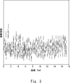
- FIG. 3 shows an example of the vibration characteristics of the optical signal received by the communication unit 21 at this time.
- the horizontal axis indicates the distance of the optical fiber 10
- the vertical axis indicates the vibration intensity.
- the position specifying unit 23 identifies two frequencies corresponding to the latitude and longitude of the current position of the vibration generator 30 by analyzing the frequency characteristics of the optical signal generated in the vicinity of the distance of 1 km of the optical fiber 10.
- the vibration generating unit 32 while moving the vibration generating unit 32, the vibration generating unit 32 generates vibration at a plurality of locations, and the distance specifying unit 22 specifies the distance of the optical fiber 10 at each of the plurality of locations, and the position specifying unit It is assumed that 23 has specified two frequencies corresponding to the latitude and longitude of the current position of the vibration generator 30.
- FIG. 4 shows an example of two frequencies corresponding to the latitude and longitude of the current position of the vibration generator 30 specified by the position specifying unit 23 in this case.
- the horizontal axis indicates the distance of the optical fiber 10
- the vertical axis indicates two frequencies corresponding to latitude and longitude.
- a frequency higher than the specified value is assigned to the first frequency corresponding to latitude, and a frequency less than the specified value is assigned to the second frequency corresponding to longitude.
- the first frequency and the second frequency are frequencies that do not overlap with each other. Therefore, even if the vibration generating unit 32 simultaneously generates vibrations of two frequencies including the first frequency and the second frequency, the position specifying unit 23 can specify the two frequencies.
- the position specifying unit 23 stores the distance of the optical fiber 10 at each of the plurality of locations and the position information in association with each other. Thereby, the position specifying unit 23 can also specify the laying route of the optical fiber 10 based on this correspondence.
- FIG. 5 shows an example of the laying route of the optical fiber 10 specified by the position specifying unit 23.
- the position where the optical fiber 10 detects the vibration is represented by the reference numeral X.
- the position specifying unit 23 may plot the position where the optical fiber 10 detects vibration on a map, and specify the laying route of the optical fiber 10 based on the plotted position.
- the position information acquisition unit 31 acquires position information representing the latitude and longitude of the current position of the vibration generator 30 at an arbitrary position (step S11).
- the vibration generation unit 32 generates vibration including the position information acquired by the position information acquisition unit 31, and applies the vibration to the optical fiber 10 (step S12).
- the optical fiber 10 detects vibration including position information (step S13).
- the optical signal transmitted through the optical fiber 10 includes the position information included in the vibration, and the communication unit 21 receives this optical signal (step S14).
- the distance specifying unit 22 specifies the distance of the optical fiber 10 from the location of the sensing device 20 (communication unit 21) to the location where the optical fiber 10 detects vibration based on the optical signal received by the communication unit 21. (Step S15).
- the position specifying unit 23 specifies the position information of the current position of the vibration generator 30 based on the optical signal received by the communication unit 21 (step S16), and the specified position information and the distance specifying unit 22 specify.
- the distance of the optical fiber 10 and the distance of the optical fiber 10 are stored in association with each other (step S17).
- the operation shown in FIG. 6 may be performed at each of a plurality of locations.
- the position specifying unit 23 stores the distance of the optical fiber 10 at each of the plurality of locations in association with the position information of the vibration generator 30. Therefore, the position specifying unit 23 may specify the laying route of the optical fiber 10 based on this association.
- the position information acquisition unit 31 acquires the position information of the current position of the vibration generator 30, and the vibration generation unit 32 acquires the position information acquired by the position information acquisition unit 31.
- the included vibration is generated, and the vibration is applied to the optical fiber 10.
- the sensing device 20 by detecting the vibration given to the optical fiber 10, the position information of the position where the optical fiber 10 detects the vibration can be acquired. At this time, the sensing device 20 does not need to be time-synchronized with the vibration generator 30. Further, since the sensing device 20 does not need to transmit information to and from the vibration generator 30 via the network, a network environment is not required. Therefore, the sensing device 20 can easily grasp the position information of the laying position of the optical fiber 10.
- the vibration generator 30 gives the optical fiber 10 vibration at a frequency corresponding to the position information of the current position, but the present invention is not limited to this.
- the vibration generator 30 may give the optical fiber 10 a vibration having an amplitude corresponding to the position information of the current position.
- the vibration generator 30 may give the optical fiber 10 vibration of a combination pattern of amplitude states such as generation and stop of vibration, which corresponds to the position information of the current position.
- the vibration pattern is not limited to the amplitude intensity, and the above-mentioned vibration pattern may be used to distinguish it from the external vibration.
- the position specifying unit 23 specifies the laying route of the optical fiber 10 based on the correspondence between the distance of the optical fiber 10 at each of the plurality of locations and the position information of the vibration generator 30. It was, but it is not limited to this. When the optical fiber 10 is laid, a surplus may be generated as shown in FIG. 7. Therefore, the position specifying unit 23 may specify the presence or absence of a surplus of the optical fiber 10 based on the correspondence between the distance of the optical fiber 10 and the position information of the vibration generator 30 at each of the plurality of locations. For example, at the positions P1 and P2 in the example of FIG. 7, the position information is almost the same, but the distances of the optical fibers 10 are different. Therefore, the position specifying unit 23 identifies that the optical fiber 10 has a surplus.
- the vibration generator 30 gives vibration including the position information of the current position to the optical fiber 10, but the present invention is not limited to this.
- a sound generator may be provided in place of the vibration generator 30, and the sound generator may give sound including position information to the optical fiber 10. For example, it is easier to give sound to an optical fiber 10 laid in a fictitious manner than to give vibration.
- FIG. 8 shows a hardware configuration example of the computer 50 that realizes the sensing device 20 according to the above-described embodiment.
- the computer 50 includes a processor 501, a memory 502, a storage 503, an input / output interface (input / output I / F) 504, a communication interface (communication I / F) 505, and the like.
- the processor 501, the memory 502, the storage 503, the input / output interface 504, and the communication interface 505 are connected by a data transmission line for transmitting and receiving data to and from each other.
- the processor 501 is, for example, an arithmetic processing unit such as a CPU (Central Processing Unit) or a GPU (Graphics Processing Unit).
- the memory 502 is, for example, a memory such as a RAM (RandomAccessMemory) or a ROM (ReadOnlyMemory).
- the storage 503 is, for example, a storage device such as an HDD (Hard Disk Drive), an SSD (Solid State Drive), or a memory card. Further, the storage 503 may be a memory such as RAM or ROM.
- the storage 503 stores a program that realizes the functions of the components included in the sensing device 20. By executing each of these programs, the processor 501 realizes the functions of the components included in the sensing device 20. Here, when executing each of the above programs, the processor 501 may read these programs on the memory 502 and then execute the programs, or may execute the programs without reading them onto the memory 502. Further, the memory 502 and the storage 503 also play a role of storing information and data held by the components included in the sensing device 20.
- Non-temporary computer-readable media include various types of tangible storage mediums.
- Examples of non-temporary computer-readable media include magnetic recording media (eg, flexible discs, magnetic tapes, hard disk drives), optomagnetic recording media (eg, optomagnetic discs), CD-ROMs (Compact Disc-ROMs), CDs. -R (CD-Recordable), CD-R / W (CD-ReWritable), semiconductor memory (for example, mask ROM, PROM (Programmable ROM), EPROM (Erasable PROM), flash ROM, RAM.
- transient computer readable medium May be supplied to the computer by various types of transient computer readable medium.
- transient computer readable media include electrical signals, optical signals, and electromagnetic waves.
- the computer-readable medium can supply the program to the computer via a wired communication path such as an electric wire and an optical fiber, or a wireless communication path.
- the input / output interface 504 is connected to a display device 5041, an input device 5042, a sound output device 5043, and the like.
- the display device 5041 is a device that displays a screen corresponding to drawing data processed by the processor 501, such as an LCD (Liquid Crystal Display), a CRT (Cathode Ray Tube) display, and a monitor.
- the input device 5042 is a device that receives an operator's operation input, and is, for example, a keyboard, a mouse, a touch sensor, and the like.
- the display device 5041 and the input device 5042 may be integrated and realized as a touch panel.
- the sound output device 5043 is a device such as a speaker that acoustically outputs sound corresponding to acoustic data processed by the processor 501.
- the communication interface 505 transmits / receives data to / from an external device.
- the communication interface 505 communicates with an external device via a wired communication path or a wireless communication path.
- the vibration generator 30 according to the above-described embodiment can also be realized by the computer 50 having the hardware configuration shown in FIG.
- the location information acquisition unit that acquires location information and A vibration generating part that generates vibration including the position information
- the optical fiber that detects the vibration and A communication unit that receives an optical signal including the position information included in the vibration, and
- a distance specifying unit that specifies the distance of the optical fiber from the location of the communication unit to the location where the optical fiber detects vibration based on the optical signal.
- a position specifying unit that identifies the position information included in the optical signal based on the optical signal and stores the distance and the position information in association with each other.
- the vibration generating unit generates vibration having a frequency corresponding to the position information.
- the position specifying unit identifies the frequency of the vibration based on the optical signal, and identifies the position information included in the optical signal based on the specified frequency.
- the position identification system described in Appendix 1. (Appendix 3)
- the position information represents latitude and longitude, and represents The vibration generating unit simultaneously generates a vibration of a first frequency corresponding to latitude and a vibration of a second frequency corresponding to longitude.
- the position information represents latitude and longitude, and represents The vibration generating unit generates a vibration of a first frequency corresponding to latitude and a vibration of a second frequency corresponding to longitude at different timings.
- the position identification system described in Appendix 2. (Appendix 5)
- the vibration generating part generates the vibration at a plurality of places, and causes the vibration.
- the distance specifying unit specifies the distance at each of the plurality of locations.
- the position specifying unit identifies the position information at each of the plurality of locations, stores the distance and the position information at each of the plurality of locations in association with each other, and stores the distance and the position at each of the plurality of locations. Identify the laying route of the optical fiber based on the correspondence with the information.
- the position identification system according to any one of Supplementary note 1 to 4.
- the location information acquisition unit that acquires location information and A vibration generating part that gives vibration including the position information to the optical fiber, A vibration generator.
- the vibration generating unit applies vibration having a frequency corresponding to the position information to the optical fiber.
- the position information represents latitude and longitude, and represents The vibration generating unit simultaneously applies vibration of a first frequency corresponding to latitude and vibration of a second frequency corresponding to longitude to the optical fiber.
- the position information represents latitude and longitude, and represents The vibration generating unit applies vibration of a first frequency corresponding to latitude and vibration of a second frequency corresponding to longitude to the optical fiber at different timings.
- the vibration generator according to Appendix 7. It is a position identification method performed by the position identification system. Steps to get location information and A vibration generation step that generates vibration including the position information, and The step of detecting the vibration by the optical fiber and A step of receiving an optical signal including the position information included in the vibration by the communication unit, and A distance specifying step for specifying the distance of the optical fiber from the location of the communication unit to the location where the optical fiber detects vibration based on the optical signal.
- Location identification methods including.
- vibration generation step vibration of a frequency corresponding to the position information is generated.
- the position specifying step the frequency of the vibration is specified based on the optical signal, and the position information included in the optical signal is specified based on the specified frequency.
- the position information represents latitude and longitude, and represents In the vibration generation step, vibration of the first frequency corresponding to latitude and vibration of the second frequency corresponding to longitude are simultaneously generated.
- the position information represents latitude and longitude, and represents In the vibration generation step, the vibration of the first frequency corresponding to the latitude and the vibration of the second frequency corresponding to the longitude are generated at different timings.
- the position specifying method according to Appendix 11.
- the vibration generation step the vibration is generated at a plurality of places.
- the distance specifying step the distance at each of the plurality of locations is specified.
- the position information at each of the plurality of locations is specified, the distance and the position information at each of the plurality of locations are stored in association with each other, and the distance and the position at each of the plurality of locations are stored. Identify the laying route of the optical fiber based on the correspondence with the information.
- the position specifying method according to any one of Supplementary note 10 to 13.
- Optical fiber 20 Sensing equipment 21 Communication unit 22 Distance identification unit 23 Position identification unit 30 Vibration generator 31 Position information acquisition unit 32 Vibration generator 50 Computer 501 Processor 502 Memory 503 Storage 504 Input / output interface 5041 Display device 5042 Input device 5043 Sound Output device 505 communication interface
Landscapes
- Physics & Mathematics (AREA)
- General Physics & Mathematics (AREA)
- Life Sciences & Earth Sciences (AREA)
- General Life Sciences & Earth Sciences (AREA)
- Geophysics (AREA)
- Geophysics And Detection Of Objects (AREA)
- Measurement Of Mechanical Vibrations Or Ultrasonic Waves (AREA)
- Position Fixing By Use Of Radio Waves (AREA)
Priority Applications (3)
| Application Number | Priority Date | Filing Date | Title |
|---|---|---|---|
| PCT/JP2020/044161 WO2022113252A1 (ja) | 2020-11-27 | 2020-11-27 | 位置特定システム、振動発生器、及び位置特定方法 |
| JP2022564920A JP7444289B2 (ja) | 2020-11-27 | 2020-11-27 | 位置特定システム、振動発生器、及び位置特定方法 |
| US18/038,146 US20240003738A1 (en) | 2020-11-27 | 2020-11-27 | Position specifying system, vibration generator, and position specifying method |
Applications Claiming Priority (1)
| Application Number | Priority Date | Filing Date | Title |
|---|---|---|---|
| PCT/JP2020/044161 WO2022113252A1 (ja) | 2020-11-27 | 2020-11-27 | 位置特定システム、振動発生器、及び位置特定方法 |
Publications (1)
| Publication Number | Publication Date |
|---|---|
| WO2022113252A1 true WO2022113252A1 (ja) | 2022-06-02 |
Family
ID=81755385
Family Applications (1)
| Application Number | Title | Priority Date | Filing Date |
|---|---|---|---|
| PCT/JP2020/044161 Ceased WO2022113252A1 (ja) | 2020-11-27 | 2020-11-27 | 位置特定システム、振動発生器、及び位置特定方法 |
Country Status (3)
| Country | Link |
|---|---|
| US (1) | US20240003738A1 (https=) |
| JP (1) | JP7444289B2 (https=) |
| WO (1) | WO2022113252A1 (https=) |
Families Citing this family (2)
| Publication number | Priority date | Publication date | Assignee | Title |
|---|---|---|---|---|
| WO2022157877A1 (ja) * | 2021-01-21 | 2022-07-28 | 日本電信電話株式会社 | 設備位置特定システム、カバー、及び設備位置特定方法 |
| CN116917703A (zh) * | 2021-02-17 | 2023-10-20 | 日本电信电话株式会社 | 电线杆位置确定方法和架空光缆的状态推定方法 |
Citations (5)
| Publication number | Priority date | Publication date | Assignee | Title |
|---|---|---|---|---|
| JPH05215864A (ja) * | 1991-08-02 | 1993-08-27 | Furukawa Electric Co Ltd:The | 光伝送路の探査方法 |
| JP2016085085A (ja) * | 2014-10-24 | 2016-05-19 | 株式会社日立製作所 | 物理探査システム及びデータ記録装置 |
| JP2019211349A (ja) * | 2018-06-05 | 2019-12-12 | 日本電信電話株式会社 | 光ファイバ経路探索方法、光ファイバ経路探索システム、信号処理装置およびプログラム |
| JP2020052030A (ja) * | 2018-09-20 | 2020-04-02 | 日本電信電話株式会社 | マンホール位置特定方法及びマンホール位置特定システム |
| US20200124735A1 (en) * | 2018-10-23 | 2020-04-23 | Nec Laboratories America, Inc | Smart optical cable positioning/location using optical fiber sensing |
-
2020
- 2020-11-27 WO PCT/JP2020/044161 patent/WO2022113252A1/ja not_active Ceased
- 2020-11-27 JP JP2022564920A patent/JP7444289B2/ja active Active
- 2020-11-27 US US18/038,146 patent/US20240003738A1/en active Pending
Patent Citations (5)
| Publication number | Priority date | Publication date | Assignee | Title |
|---|---|---|---|---|
| JPH05215864A (ja) * | 1991-08-02 | 1993-08-27 | Furukawa Electric Co Ltd:The | 光伝送路の探査方法 |
| JP2016085085A (ja) * | 2014-10-24 | 2016-05-19 | 株式会社日立製作所 | 物理探査システム及びデータ記録装置 |
| JP2019211349A (ja) * | 2018-06-05 | 2019-12-12 | 日本電信電話株式会社 | 光ファイバ経路探索方法、光ファイバ経路探索システム、信号処理装置およびプログラム |
| JP2020052030A (ja) * | 2018-09-20 | 2020-04-02 | 日本電信電話株式会社 | マンホール位置特定方法及びマンホール位置特定システム |
| US20200124735A1 (en) * | 2018-10-23 | 2020-04-23 | Nec Laboratories America, Inc | Smart optical cable positioning/location using optical fiber sensing |
Also Published As
| Publication number | Publication date |
|---|---|
| JPWO2022113252A1 (https=) | 2022-06-02 |
| JP7444289B2 (ja) | 2024-03-06 |
| US20240003738A1 (en) | 2024-01-04 |
Similar Documents
| Publication | Publication Date | Title |
|---|---|---|
| US11366231B2 (en) | Smart optical cable positioning/location using optical fiber sensing | |
| US11060950B1 (en) | Systems and methods for identifying locations of deployed fiber cables based on vibrations | |
| WO2020116030A1 (ja) | 道路監視システム、道路監視装置、道路監視方法、及び非一時的なコンピュータ可読媒体 | |
| WO2022113252A1 (ja) | 位置特定システム、振動発生器、及び位置特定方法 | |
| WO2021010251A1 (ja) | 光ファイバセンシングシステム、光ファイバセンシング機器、及び異常判断方法 | |
| WO2024184959A1 (ja) | 光ファイバセンシングシステム、光ファイバセンシング装置、及び光ファイバセンシング方法 | |
| WO2021176581A1 (ja) | 監視システム、監視装置、及び監視方法 | |
| CN114997232B (zh) | 用于确定光缆走向的方法、处理器及存储介质 | |
| CN114993217B (zh) | 用于确定光缆的盘留长度的方法、处理器及存储介质 | |
| WO2021152787A1 (ja) | 構造物劣化検出システム、構造物劣化検出方法、及び構造物劣化検出装置 | |
| JP7718501B2 (ja) | 光ファイバセンシングシステム、光ファイバセンシング機器、及び光ファイバセンシング方法 | |
| US10644749B2 (en) | Cable tracking by electromagnetic emission | |
| JP2025005067A (ja) | 光ファイバセンシングシステム、制御装置、及び制御方法 | |
| JP2025006751A (ja) | 光ファイバセンシングシステム、光ファイバセンシング装置、及びマンホール検知方法 | |
| JP2025006752A (ja) | 光ファイバセンシングシステム、光ファイバセンシング装置、及び光ファイバセンシング方法 | |
| US12560474B2 (en) | Laid state identifying system, laid state identifying apparatus, and laid state identifying method | |
| US20250003791A1 (en) | Optical fiber sensing system, optical fiber sensing apparatus, and route determination method | |
| WO2022201342A1 (ja) | 雷撃検出装置、雷撃検出システム及び雷撃検出方法 | |
| US20240361178A1 (en) | Monitoring system, monitoring apparatus, and monitoring method | |
| US12618993B2 (en) | Relaying apparatus including a fiber sensing system for submarine use | |
| US20240230936A9 (en) | Fiber sensing system, relaying apparatus, and fiber sensing method | |
| Shen et al. | Development of high-speed Wi-Fi wireless acoustic emission system | |
| JP7347646B2 (ja) | 停電検出システム、停電検出装置、及び停電検出方法 | |
| JP7552858B2 (ja) | 補正システム、補正装置、及び補正方法 | |
| US20240353253A1 (en) | Detection system, detection apparatus, and detection method |
Legal Events
| Date | Code | Title | Description |
|---|---|---|---|
| 121 | Ep: the epo has been informed by wipo that ep was designated in this application |
Ref document number: 20963517 Country of ref document: EP Kind code of ref document: A1 |
|
| ENP | Entry into the national phase |
Ref document number: 2022564920 Country of ref document: JP Kind code of ref document: A |
|
| NENP | Non-entry into the national phase |
Ref country code: DE |
|
| 122 | Ep: pct application non-entry in european phase |
Ref document number: 20963517 Country of ref document: EP Kind code of ref document: A1 |