WO2022113177A1 - On-board control device and acceleration sensor diagnostic method - Google Patents
On-board control device and acceleration sensor diagnostic method Download PDFInfo
- Publication number
- WO2022113177A1 WO2022113177A1 PCT/JP2020/043698 JP2020043698W WO2022113177A1 WO 2022113177 A1 WO2022113177 A1 WO 2022113177A1 JP 2020043698 W JP2020043698 W JP 2020043698W WO 2022113177 A1 WO2022113177 A1 WO 2022113177A1
- Authority
- WO
- WIPO (PCT)
- Prior art keywords
- train
- acceleration
- acceleration sensor
- control device
- board
- Prior art date
Links
- 230000001133 acceleration Effects 0.000 title claims abstract description 220
- 238000002405 diagnostic procedure Methods 0.000 title claims description 7
- 238000001514 detection method Methods 0.000 claims abstract description 46
- 238000004891 communication Methods 0.000 claims abstract description 19
- 238000000034 method Methods 0.000 claims description 12
- 230000002159 abnormal effect Effects 0.000 claims description 9
- 230000005484 gravity Effects 0.000 claims description 3
- 238000012545 processing Methods 0.000 description 30
- 238000012937 correction Methods 0.000 description 17
- 238000010586 diagram Methods 0.000 description 10
- 238000009434 installation Methods 0.000 description 9
- 230000006870 function Effects 0.000 description 7
- 101100425901 Rattus norvegicus Tpm1 gene Proteins 0.000 description 6
- 238000005259 measurement Methods 0.000 description 4
- 101001012662 Homo sapiens MIF4G domain-containing protein Proteins 0.000 description 2
- 102100029806 MIF4G domain-containing protein Human genes 0.000 description 2
- 230000005540 biological transmission Effects 0.000 description 2
- 238000003745 diagnosis Methods 0.000 description 2
- 239000002131 composite material Substances 0.000 description 1
- 238000007796 conventional method Methods 0.000 description 1
- 230000000694 effects Effects 0.000 description 1
- 230000003287 optical effect Effects 0.000 description 1
- 239000004065 semiconductor Substances 0.000 description 1
Images


Classifications
-
- G—PHYSICS
- G01—MEASURING; TESTING
- G01P—MEASURING LINEAR OR ANGULAR SPEED, ACCELERATION, DECELERATION, OR SHOCK; INDICATING PRESENCE, ABSENCE, OR DIRECTION, OF MOVEMENT
- G01P21/00—Testing or calibrating of apparatus or devices covered by the preceding groups
-
- B—PERFORMING OPERATIONS; TRANSPORTING
- B60—VEHICLES IN GENERAL
- B60L—PROPULSION OF ELECTRICALLY-PROPELLED VEHICLES; SUPPLYING ELECTRIC POWER FOR AUXILIARY EQUIPMENT OF ELECTRICALLY-PROPELLED VEHICLES; ELECTRODYNAMIC BRAKE SYSTEMS FOR VEHICLES IN GENERAL; MAGNETIC SUSPENSION OR LEVITATION FOR VEHICLES; MONITORING OPERATING VARIABLES OF ELECTRICALLY-PROPELLED VEHICLES; ELECTRIC SAFETY DEVICES FOR ELECTRICALLY-PROPELLED VEHICLES
- B60L3/00—Electric devices on electrically-propelled vehicles for safety purposes; Monitoring operating variables, e.g. speed, deceleration or energy consumption
- B60L3/0023—Detecting, eliminating, remedying or compensating for drive train abnormalities, e.g. failures within the drive train
- B60L3/0038—Detecting, eliminating, remedying or compensating for drive train abnormalities, e.g. failures within the drive train relating to sensors
-
- B—PERFORMING OPERATIONS; TRANSPORTING
- B60—VEHICLES IN GENERAL
- B60L—PROPULSION OF ELECTRICALLY-PROPELLED VEHICLES; SUPPLYING ELECTRIC POWER FOR AUXILIARY EQUIPMENT OF ELECTRICALLY-PROPELLED VEHICLES; ELECTRODYNAMIC BRAKE SYSTEMS FOR VEHICLES IN GENERAL; MAGNETIC SUSPENSION OR LEVITATION FOR VEHICLES; MONITORING OPERATING VARIABLES OF ELECTRICALLY-PROPELLED VEHICLES; ELECTRIC SAFETY DEVICES FOR ELECTRICALLY-PROPELLED VEHICLES
- B60L3/00—Electric devices on electrically-propelled vehicles for safety purposes; Monitoring operating variables, e.g. speed, deceleration or energy consumption
- B60L3/10—Indicating wheel slip ; Correction of wheel slip
- B60L3/104—Indicating wheel slip ; Correction of wheel slip by indirect measurement of vehicle speed
-
- B—PERFORMING OPERATIONS; TRANSPORTING
- B61—RAILWAYS
- B61L—GUIDING RAILWAY TRAFFIC; ENSURING THE SAFETY OF RAILWAY TRAFFIC
- B61L25/00—Recording or indicating positions or identities of vehicles or trains or setting of track apparatus
- B61L25/02—Indicating or recording positions or identities of vehicles or trains
- B61L25/025—Absolute localisation, e.g. providing geodetic coordinates
-
- G—PHYSICS
- G01—MEASURING; TESTING
- G01C—MEASURING DISTANCES, LEVELS OR BEARINGS; SURVEYING; NAVIGATION; GYROSCOPIC INSTRUMENTS; PHOTOGRAMMETRY OR VIDEOGRAMMETRY
- G01C22/00—Measuring distance traversed on the ground by vehicles, persons, animals or other moving solid bodies, e.g. using odometers, using pedometers
- G01C22/02—Measuring distance traversed on the ground by vehicles, persons, animals or other moving solid bodies, e.g. using odometers, using pedometers by conversion into electric waveforms and subsequent integration, e.g. using tachometer generator
-
- G—PHYSICS
- G01—MEASURING; TESTING
- G01P—MEASURING LINEAR OR ANGULAR SPEED, ACCELERATION, DECELERATION, OR SHOCK; INDICATING PRESENCE, ABSENCE, OR DIRECTION, OF MOVEMENT
- G01P15/00—Measuring acceleration; Measuring deceleration; Measuring shock, i.e. sudden change of acceleration
- G01P15/02—Measuring acceleration; Measuring deceleration; Measuring shock, i.e. sudden change of acceleration by making use of inertia forces using solid seismic masses
- G01P15/08—Measuring acceleration; Measuring deceleration; Measuring shock, i.e. sudden change of acceleration by making use of inertia forces using solid seismic masses with conversion into electric or magnetic values
-
- B—PERFORMING OPERATIONS; TRANSPORTING
- B60—VEHICLES IN GENERAL
- B60L—PROPULSION OF ELECTRICALLY-PROPELLED VEHICLES; SUPPLYING ELECTRIC POWER FOR AUXILIARY EQUIPMENT OF ELECTRICALLY-PROPELLED VEHICLES; ELECTRODYNAMIC BRAKE SYSTEMS FOR VEHICLES IN GENERAL; MAGNETIC SUSPENSION OR LEVITATION FOR VEHICLES; MONITORING OPERATING VARIABLES OF ELECTRICALLY-PROPELLED VEHICLES; ELECTRIC SAFETY DEVICES FOR ELECTRICALLY-PROPELLED VEHICLES
- B60L2200/00—Type of vehicles
- B60L2200/26—Rail vehicles
-
- B—PERFORMING OPERATIONS; TRANSPORTING
- B60—VEHICLES IN GENERAL
- B60L—PROPULSION OF ELECTRICALLY-PROPELLED VEHICLES; SUPPLYING ELECTRIC POWER FOR AUXILIARY EQUIPMENT OF ELECTRICALLY-PROPELLED VEHICLES; ELECTRODYNAMIC BRAKE SYSTEMS FOR VEHICLES IN GENERAL; MAGNETIC SUSPENSION OR LEVITATION FOR VEHICLES; MONITORING OPERATING VARIABLES OF ELECTRICALLY-PROPELLED VEHICLES; ELECTRIC SAFETY DEVICES FOR ELECTRICALLY-PROPELLED VEHICLES
- B60L2240/00—Control parameters of input or output; Target parameters
- B60L2240/10—Vehicle control parameters
- B60L2240/12—Speed
-
- B—PERFORMING OPERATIONS; TRANSPORTING
- B60—VEHICLES IN GENERAL
- B60L—PROPULSION OF ELECTRICALLY-PROPELLED VEHICLES; SUPPLYING ELECTRIC POWER FOR AUXILIARY EQUIPMENT OF ELECTRICALLY-PROPELLED VEHICLES; ELECTRODYNAMIC BRAKE SYSTEMS FOR VEHICLES IN GENERAL; MAGNETIC SUSPENSION OR LEVITATION FOR VEHICLES; MONITORING OPERATING VARIABLES OF ELECTRICALLY-PROPELLED VEHICLES; ELECTRIC SAFETY DEVICES FOR ELECTRICALLY-PROPELLED VEHICLES
- B60L2240/00—Control parameters of input or output; Target parameters
- B60L2240/10—Vehicle control parameters
- B60L2240/14—Acceleration
- B60L2240/16—Acceleration longitudinal
-
- B—PERFORMING OPERATIONS; TRANSPORTING
- B60—VEHICLES IN GENERAL
- B60L—PROPULSION OF ELECTRICALLY-PROPELLED VEHICLES; SUPPLYING ELECTRIC POWER FOR AUXILIARY EQUIPMENT OF ELECTRICALLY-PROPELLED VEHICLES; ELECTRODYNAMIC BRAKE SYSTEMS FOR VEHICLES IN GENERAL; MAGNETIC SUSPENSION OR LEVITATION FOR VEHICLES; MONITORING OPERATING VARIABLES OF ELECTRICALLY-PROPELLED VEHICLES; ELECTRIC SAFETY DEVICES FOR ELECTRICALLY-PROPELLED VEHICLES
- B60L2240/00—Control parameters of input or output; Target parameters
- B60L2240/40—Drive Train control parameters
- B60L2240/46—Drive Train control parameters related to wheels
- B60L2240/461—Speed
-
- B—PERFORMING OPERATIONS; TRANSPORTING
- B60—VEHICLES IN GENERAL
- B60L—PROPULSION OF ELECTRICALLY-PROPELLED VEHICLES; SUPPLYING ELECTRIC POWER FOR AUXILIARY EQUIPMENT OF ELECTRICALLY-PROPELLED VEHICLES; ELECTRODYNAMIC BRAKE SYSTEMS FOR VEHICLES IN GENERAL; MAGNETIC SUSPENSION OR LEVITATION FOR VEHICLES; MONITORING OPERATING VARIABLES OF ELECTRICALLY-PROPELLED VEHICLES; ELECTRIC SAFETY DEVICES FOR ELECTRICALLY-PROPELLED VEHICLES
- B60L2240/00—Control parameters of input or output; Target parameters
- B60L2240/60—Navigation input
- B60L2240/64—Road conditions
- B60L2240/642—Slope of road
-
- Y—GENERAL TAGGING OF NEW TECHNOLOGICAL DEVELOPMENTS; GENERAL TAGGING OF CROSS-SECTIONAL TECHNOLOGIES SPANNING OVER SEVERAL SECTIONS OF THE IPC; TECHNICAL SUBJECTS COVERED BY FORMER USPC CROSS-REFERENCE ART COLLECTIONS [XRACs] AND DIGESTS
- Y02—TECHNOLOGIES OR APPLICATIONS FOR MITIGATION OR ADAPTATION AGAINST CLIMATE CHANGE
- Y02T—CLIMATE CHANGE MITIGATION TECHNOLOGIES RELATED TO TRANSPORTATION
- Y02T90/00—Enabling technologies or technologies with a potential or indirect contribution to GHG emissions mitigation
- Y02T90/10—Technologies relating to charging of electric vehicles
- Y02T90/16—Information or communication technologies improving the operation of electric vehicles
Definitions
- the present disclosure relates to an on-board control device mounted on a train equipped with an acceleration sensor and an acceleration sensor diagnostic method.
- the on-board control device mounted on the train calculates the train position using a speed generator, on-board child, etc. Then, based on the calculated train position, the brake pattern for controlling the train interval is calculated. Therefore, it is important that the on-board control device accurately manages the train position.
- the on-board control device calculates the train position, train speed, etc. using a speed generator, a on-board element, or the like, if the wheels of the train slip or slide, the error in the train position becomes large.
- Patent Document 1 discloses a technique in which a vehicle control system diagnoses the soundness of an acceleration sensor.
- the vehicle control system is provided with a vibration source for giving vibration to the acceleration sensor in order to diagnose the soundness of the acceleration sensor. Therefore, there is a problem that the device configuration becomes complicated in the vehicle control system.
- the present disclosure has been made in view of the above, and an object of the present invention is to obtain an on-board control device capable of periodically diagnosing the soundness of an acceleration sensor with a simple configuration.
- the present disclosure is an on-board control device mounted on a train.
- the on-board control device is a speed generator that outputs a pulse corresponding to the number of rotations of the wheels of the train, an on-board element that receives a message including identification information of the ground element from the ground element, and a detection axis that matches the traveling direction of the train.
- a communication unit that can communicate with the acceleration sensor and master controller installed in the train, a storage unit that stores information on the gradient value at each position of the line on which the train travels, and information acquired from the on-board child and speed generator.
- It is used to identify the train position of the train, determine the running state of the train from the information acquired from the master controller, and when the train is coasting or stopped, the first acceleration of the train output from the acceleration sensor and the gravity acceleration. It is characterized by comprising a control unit for diagnosing the soundness of the acceleration sensor based on a comparison result comparing the second acceleration in the traveling direction of the train calculated by using the gradient value of the train position.
- the on-board control device has the effect of being able to periodically diagnose the soundness of the accelerometer with a simple configuration.
- the figure which shows the installation example of the acceleration sensor provided in the train which concerns on Embodiment 1. A block diagram showing a configuration example of the on-vehicle control device according to the first embodiment.
- the figure which shows the example of the case where the processing circuit provided in the vehicle-mounted control device which concerns on Embodiment 1 is configured by a processor and a memory.
- the figure which shows the example of the case where the processing circuit provided in the vehicle-mounted control device according to the first embodiment is configured by dedicated hardware.
- FIG. 1 is a diagram showing a configuration example of the train control system 100 according to the first embodiment.
- the train control system 100 includes a train 10, a ground element 11, a ground radio device 12, and a ground device 13.
- the train 10 includes an acceleration sensor 1, an on-board control device 2, an on-board element 3, a master controller 4, a speed generator 5, an on-board radio device 6, an on-board antenna 7, and a brake device 8. , Propulsion control device 9.
- the acceleration sensor 1 has a first detection axis, which is a detection axis, installed in line with the traveling direction of the train 10.
- FIG. 2 is a diagram showing an installation example of the acceleration sensor 1 included in the train 10 according to the first embodiment.
- the traveling direction of the train 10 is the direction indicated by the arrow 80.
- the traveling direction of the train 10 is represented as the x-axis.
- the acceleration sensor 1 detects the first acceleration, which is the acceleration in the traveling direction of the train 10, and outputs the first acceleration to the on-board control device 2.
- FIG. 2 shows the gradient value at the train position of the train 10, which will be described later, and the gravitational acceleration g applied to the train 10.
- the on-board element 3 receives a message including an ID (IDentifier) that is identification information of the ground element 11 from the ground element 11 installed on the ground, and outputs the ID of the ground element 11 to the on-board control device 2.
- ID IDentifier
- the master controller 4 is installed in the driver's seat (not shown) of the train 10 and accepts the driver's operation.
- FIG. 1 shows an example in which the train 10 includes a master controller 4 in a leading car and a trailing car.
- the master controller 4 outputs information on the operating state such as the power running notch and the brake notch received from the driver to the on-board control device 2.
- the information on the operating states such as the power running notch and the brake notch output from the master controller 4 to the on-board control device 2 is information indicating the running state of the train 10, for example, whether the train 10 is in an accelerating state or a decelerating state. This is information indicating whether the vehicle is coasting or coasting.
- the speed generator 5 generates a number of pulses corresponding to the rotation speed of the wheels of the train 10, and outputs the generated pulses to the on-board control device 2.
- the on-board wireless device 6 performs wireless communication with the terrestrial wireless device 12.
- the on-board wireless device 6 transmits data such as position information of the train 10 calculated by the on-board control device 2 and acquired from the on-board control device 2 to the terrestrial wireless device 12 by wireless communication via the on-board antenna 7. do.
- the on-board wireless device 6 receives control information such as the stop limit information of the train 10 calculated by the ground device 13 from the terrestrial wireless device 12 via the on-board antenna 7 by wireless communication.
- the brake device 8 performs deceleration processing, stop processing, etc. of the train 10 based on the brake command from the on-board control device 2.
- the propulsion control device 9 drives an electric motor that rotates the wheels based on a drive command from the on-board control device 2, and accelerates the train 10.
- the on-board control device 2 is mounted on the train 10 and controls the running and stopping of the train 10 when the train 10 is in operation.
- the on-board control device 2 periodically calculates the train position of the train 10. Specifically, the on-board control device 2 calculates the train speed, travel distance, etc. of the train 10 from the number of pulses acquired from the speed generator 5 and the diameter of the wheels of the train 10, and further acquires them from the on-board element 3.
- the train position of the train 10 is calculated by using the message, that is, the position information of the ground element 11.
- the on-board control device 2 transmits the calculated position information to the on-board radio device 12 via the on-board radio device 6 and the on-board antenna 7.
- the on-board control device 2 receives the stop limit information of the train 10 calculated by the on-board device 13 from the on-board radio device 12 via the on-board antenna 7 and the on-board radio device 6.
- the on-board control device 2 generates a stop / deceleration pattern using stop limit information and the like, and controls the running of the train 10 using the generated stop / deceleration pattern.
- the on-board control device 2 outputs a brake command to the brake device 8 when the train speed of the train 10 exceeds the stop / deceleration pattern.
- the on-board control device 2 periodically diagnoses the soundness of the acceleration sensor 1. The operation of the on-board control device 2 to periodically diagnose the soundness of the acceleration sensor 1 will be described later.
- the ground system which is a device installed on the ground, includes a ground element 11, a ground radio device 12, and a ground device 13.
- the ground element 11 transmits a telegram including an ID which is identification information of the ground element 11.
- an ID which is identification information of the ground element 11.
- a plurality of ground elements 11 are installed at predetermined intervals on the line on which the train 10 travels.
- the terrestrial wireless device 12 performs wireless communication with the on-board wireless device 6 via the train 10, specifically, the on-board antenna 7.
- the terrestrial wireless device 12 receives data such as the position information of the train 10 calculated by the train 10 by wireless communication.
- the ground radio device 12 transmits control information such as stop limit information of the train 10 calculated by the ground device 13 to the train 10 by wireless communication.
- the ground device 13 is connected to the ground radio device 12, and receives the position information of the train 10 from the on-board control device 2 of the train 10 via the on-board radio device 6, the on-board antenna 7, and the ground radio device 12. It manages the position information of the train 10 traveling in the jurisdiction area. In the example of FIG. 1, there is only one train 10, but the ground device 13 can manage the position information of a plurality of trains 10. When a plurality of trains 10 are traveling in the jurisdiction area, the ground device 13 manages the interval between the plurality of trains 10, so that the stop limit of the plurality of trains 10 is set based on the position information of the plurality of trains 10. Calculate.
- the ground device 13 transmits stop limit information indicating the stop limit of the train 10 obtained by calculation to the on-board control device 2 of the train 10 via the ground radio device 12, the on-board antenna 7, and the on-board radio device 6. do. Further, the ground device 13 generates control information such as deceleration information based on the position information of the plurality of trains 10, and of the train 10 via the ground radio device 12, the on-board antenna 7, and the on-board radio device 6. It is transmitted to the on-board control device 2.
- the train control system 100 shows an example of application to a wireless train control system in the example of FIG. 1, but is not limited to this.
- the train control system 100 includes a digital ATC device in which the ground device 13 detects the train positions of a plurality of trains 10 using a track circuit and transmits the position of the preceding train to the on-board control device 2 via the track circuit. It is also applicable to the system.
- FIG. 3 is a block diagram showing a configuration example of the on-vehicle control device 2 according to the first embodiment.
- the on-vehicle control device 2 includes a communication unit 21, a storage unit 22, and a control unit 23.
- the communication unit 21 communicates with the acceleration sensor 1, the on-board element 3, the master controller 4, the speed generator 5, the on-board radio device 6, the brake device 8, and the propulsion control device 9.
- the storage unit 22 stores information on the gradient value at each position of the route on which the train 10 travels, and information in which the ID of the ground element 11 and the installation position of the ground element 11 are associated with each other.
- FIG. 4 is a diagram showing an example of information stored in the storage unit 22 of the on-board control device 2 according to the first embodiment.
- FIG. 4 shows an example in which the storage unit 22 stores each of the above-mentioned information in the form of a database.
- the storage unit 22 stores a specific gradient value, a start position of the gradient according to the gradient value, and an end position of the gradient according to the gradient value as information on the gradient value at each position of the line on which the train 10 travels. ..
- the storage unit 22 stores the ID of each ground element 11 and the information of the installation position as the information in which the ID of the ground element 11 and the installation position of the ground element 11 are associated with each other.
- the control unit 23 specifies the train position of the train 10 by using the information acquired from the on-board element 3 and the speed generator 5. Specifically, the control unit 23 uses the ID of the ground element 11 received from the ground element 11 via the on-board element 3 and the communication unit 21 and the ID of the ground element 11 stored in the storage unit 22. The train position of the train 10 is specified by using the corresponding installation position of the ground element 11. The control unit 23 calculates the moving distance from the ground element 11 by the number of pulses corresponding to the rotation speed of the wheels obtained from the speed generator 5, and updates the train position of the train 10 at any time. The control unit 23 determines the running state of the train 10 from the information acquired from the master controller 4.
- the control unit 23 determines whether the train 10 is accelerating, decelerating, coasting, or stopped.
- the control unit 23 calculates using the first acceleration, which is the acceleration of the train 10 output from the acceleration sensor 1, the gravity acceleration g, and the gradient value of the train position of the train 10 when the train 10 is coasting or stopped.
- the second acceleration is a train traveling direction component of the gravitational acceleration g.
- the control unit 23 diagnoses the soundness of the acceleration sensor 1 based on the comparison result.
- the wheels may slip or slide.
- the number of pulses generated by the speed generator 5 does not match the actual train speed, travel distance, and the like of the train 10. Therefore, the on-board control device 2 determines whether or not the wheels of the train 10 have slipped or slipped, and performs a process of correcting the train position of the train 10 when the slip or slip occurs.
- the acceleration sensor 1 is not affected by wheel idling, sliding, or the like.
- the on-board control device 2 uses the acceleration output from the acceleration sensor 1 which is not affected by the wheel slipping or sliding to slip or slide the wheel. It is preferable to detect and correct when slipping or slipping occurs. Therefore, the on-board control device 2 periodically diagnoses the soundness of the acceleration sensor 1.
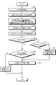
- FIG. 5 is a flowchart showing the operation of the on-board control device 2 according to the first embodiment.
- the communication unit 21 performs communication with other configurations, and the control unit 23 performs all other operations. Therefore, in order to simplify the description, the on-vehicle control device 2 will be mainly described.
- the on-board control device 2 determines whether or not the acceleration sensor 1 is normal (step S101). The operation of determining whether or not the acceleration sensor 1 is normal in the on-vehicle control device 2 will be described in detail.
- FIG. 6 is a flowchart showing an operation of determining whether or not the acceleration sensor 1 is normal in the on-vehicle control device 2 according to the first embodiment. The flowchart shown in FIG. 6 shows the details of the operation of step S101 of the flowchart shown in FIG.
- the on-vehicle control device 2 acquires the ID of the ground element 11 via the on-vehicle element 3 (step S201).
- the on-board control device 2 identifies the position corresponding to the ID of the ground element 11 based on the information in which the ID of the ground element 11 stored in the storage unit 22 and the installation position of the ground element 11 are associated with each other.
- Step S202 The on-board control device 2 acquires a pulse corresponding to the rotation speed of the wheels of the train 10 from the speed generator 5, calculates the moving distance from the ground element 11, and updates the train position x of the train 10 at any time (step).
- S203 The on-board control device 2 specifies the gradient value Gx at the train position x of the train 10 (step S204).
- the storage unit 22 stores the gradient value at each position of the line on which the train 10 travels, that is, the gradient value Gx corresponding to the train position x of the train 10.
- the on-vehicle control device 2 acquires information on the running state of the train 10 from the master controller 4 (step S205).
- step S206: Yes When the train 10 is coasting (step S206: Yes), or when the train 10 is not coasting (step S206: No) but the train 10 is stopped (step S207: Yes), the on-board control device 2 is used. It is determined whether or not the first acceleration detected by the acceleration sensor 1 and the second acceleration, which is a component of the gravitational acceleration g in the train traveling direction, match (step S208). If the train 10 is coasting (step S206: Yes) or stopped (step S207: Yes), the first acceleration output from the acceleration sensor 1 does not occur except for the acceleration caused by the gravitational acceleration g.
- the second acceleration that is, the gravitational acceleration g, has the same value as the train traveling direction component g ⁇ sin ⁇ g ⁇ Gx.
- the on-board control device 2 calculates the difference between the first acceleration ( ⁇ _Sen_x) and the second acceleration (g ⁇ Gx) in consideration of the measurement error of the acceleration sensor 1, and the absolute value of the difference is the first. If it is within the threshold value THRE1 of, it may be determined that they match.
- the first threshold value THRE1 is a predetermined threshold value in consideration of the measurement error of the acceleration sensor 1, and is stored by, for example, the storage unit 22. Since the on-board control device 2 acquires the running state information from the master controller 4, it can detect whether the train 10 is in the accelerating state, the decelerating state, or the coasting state. Further, since the on-vehicle control device 2 mainly supplies a pulse corresponding to the rotation speed of the wheels from the speed generator 5, it can detect whether the train 10 is stopped.
- step S208: No When the first acceleration and the second acceleration do not match (step S208: No), the on-board control device 2 determines that the acceleration sensor 1 is abnormal (step S209). When the first acceleration and the second acceleration match (step S208: Yes), the on-board control device 2 determines that the acceleration sensor 1 is normal (step S210). When the train 10 is not coasting (step S206: No) and the train 10 is not stopped (step S207: No), the on-board control device 2 diagnoses the soundness of the acceleration sensor 1 in this operation. However, the acceleration sensor 1 is regarded as normal (step S211), and the acceleration sensor 1 is determined to be normal (step S210).
- step S101 When the acceleration sensor 1 is normal (step S101: Yes), the on-board control device 2 detects slipping or slipping using the speed generator 5 and the acceleration sensor 1, and performs correction processing when slipping or slipping is detected. It is carried out (step S102).
- FIG. 7 shows an operation in which the on-board control device 2 according to the first embodiment detects slipping or slipping by using the speed generator 5 and the acceleration sensor 1 when the acceleration sensor 1 is normal, and performs correction processing. It is a flowchart.
- the on-board control device 2 calculates a third acceleration ( ⁇ _TM) from the pulse output from the speed generator 5.
- the on-vehicle control device 2 compares the calculated third acceleration ( ⁇ _TM) with the first acceleration ( ⁇ _Sen_x) detected by the acceleration sensor 1. Specifically, the on-board control device 2 calculates the difference between the third acceleration ( ⁇ _TM) and the first acceleration ( ⁇ _Sen_x).
- the on-board control device 2 When the difference between the third acceleration ( ⁇ _TM) and the first acceleration ( ⁇ _Sen_x) is larger than the first idling threshold SLIP1 for detecting idling (step S301: Yes), the on-board control device 2 is a train. It is determined that slipping has occurred on the 10 wheels, and correction processing is performed (step S302). Specifically, the on-board control device 2 calculates the train speed and the train position of the train 10 using the first acceleration ( ⁇ _Sen_x) output from the acceleration sensor 1 while the idling state continues.
- Step S301 When the difference between the third acceleration ( ⁇ _TM) and the first acceleration ( ⁇ _Sen_x) is equal to or less than the first slip threshold SLIP1 (step S301: No) and smaller than the first gliding threshold SLIDE1 for detecting gliding. (Step S303: Yes), the on-board control device 2 determines that gliding has occurred on the wheels of the train 10, and performs correction processing (step S304). Specifically, the on-vehicle control device 2 calculates the train speed and the train position of the train 10 using the first acceleration ( ⁇ _Sen_x) output from the acceleration sensor 1 while the sliding state continues.
- step S303: No When the difference between the third acceleration ( ⁇ _TM) and the first acceleration ( ⁇ _Sen_x) is equal to or greater than the first gliding threshold value SLIDE1 (step S303: No), the on-board control device 2 glides on the wheels of the train 10. Is not generated, and it is determined that the correction process is unnecessary (step S305). In this way, the on-board control device 2 determines the presence or absence of idling based on the comparison result of comparing the calculated difference with the first idling threshold value for detecting idling, and detects the calculated difference and gliding. The presence or absence of gliding is determined based on the comparison result of comparison with the first gliding threshold value for the purpose.
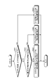
- FIG. 8 is a flowchart showing an operation in which the on-board control device 2 according to the first embodiment detects slipping or slipping by using the speed generator 5 and performs correction processing when the acceleration sensor 1 is abnormal.
- the on-board control device 2 calculates the fourth acceleration of the train 10 from the increment of the pulse per unit time of the speed generator 5.
- the on-board control device 2 has a pulse number P1 between t1 seconds and t2 seconds per unit time T0 of the speed generator 5, and between t2 seconds and t3 seconds, which is the next unit time T0.
- the fourth acceleration of the train 10 is calculated by using the pulse number P1 + N1 in which the N1 pulse is increased.
- step S401 When the fourth acceleration is larger than the second idling threshold SLIP2 for detecting idling (step S401: Yes), the on-board control device 2 determines that idling has occurred on the wheels of the train 10, and corrects the process. (Step S402). Specifically, when the on-board control device 2 detects idling, it calculates the train position of the train 10 based on the pulse of the speed generator 5, and the calculated head position of the train 10 is the actual train 10. The pulse signal of the speed generator 5 is used as it is because it is in front of the head position and a margin for control is secured.
- the on-board control device 2 calculates the tail position of the train 10 so that a control margin is secured by, for example, calculating the train position of the train 10 on the premise that the train is traveling at a constant speed from m1 second before the slip detection is detected. multiply.
- the on-board control device 2 determines. It is determined that gliding has occurred on the wheels of the train 10, and correction processing is performed (step S404). Specifically, when the on-board control device 2 detects gliding, it calculates the train position of the train 10 based on the pulse signal of the speed generator 5, and the calculated head position of the train 10 is the actual train 10. Since it is after the head position of the brake pattern and the distance from the brake pattern is judged to be larger than the actual distance, the brake output timing is determined, so that there is no control margin.
- the on-board control device 2 is controlled by, for example, calculating the train position of the train 10 on the assumption that the train is traveling at a constant speed from m2 seconds before the gliding is detected. Make corrections to secure a margin.
- the calculated tail position of the train 10 is later than the actual tail position of the train 10, and the stop limit position of the following train is calculated so as to have a control margin. Is secured, so the pulse signal of the speed generator 5 is used as it is.
- the on-board control device 2 determines that neither idling nor gliding has occurred on the wheels of the train 10, and correction processing is unnecessary. Determination (step S405). As described above, the on-board control device 2 determines the presence or absence of idling based on the comparison result of comparing the fourth acceleration and the threshold value for detecting idling, and detects the fourth acceleration and gliding. The presence or absence of gliding is determined based on the comparison result of comparison with the threshold value.
- step S101: No the on-board control device 2 does not use the signal of the acceleration sensor 1, but detects idling or sliding only by the pulse signal of the speed generator 5, and slips or slips. Correction is performed when gliding is detected.
- the on-board control device 2 since the true train position, train speed, acceleration, etc. of the train 10 in which idling or sliding is occurring are unknown, the on-board control device 2 has a physical limit value and performance in order to secure a control margin. It becomes necessary to perform excessive speed correction and position correction by using, for example, the maximum acceleration of the train, the maximum deceleration of the train, the maximum gradient, etc., such as the target limit value. Therefore, in the train control system 100, there may be a case where the train spacing of the plurality of trains 10 becomes larger than necessary.
- step S101: Yes when the acceleration sensor 1 is normal (step S101: Yes), the on-board control device 2 uses the signal of the acceleration sensor 1 which is not affected even when the wheels of the train 10 slip or slide, and the train is used. It is possible to detect slipping or slipping of 10 wheels and make corrections when slipping or slipping is detected. As a result, the train control system 100 ensures stable transportation density without taking a train interval larger than necessary.
- the communication unit 21 is an interface such as a communication device.
- the storage unit 22 is a memory.
- the control unit 23 is realized by a processing circuit.
- the processing circuit may be a processor and memory for executing a program stored in the memory, or may be dedicated hardware.
- FIG. 9 is a diagram showing an example in which the processing circuit 90 included in the on-board control device 2 according to the first embodiment is configured by the processor 91 and the memory 92.
- the processing circuit 90 is composed of the processor 91 and the memory 92, each function of the processing circuit 90 of the on-board control device 2 is realized by software, firmware, or a combination of software and firmware.
- the software or firmware is written as a program and stored in the memory 92.
- each function is realized by the processor 91 reading and executing the program stored in the memory 92. That is, the processing circuit 90 includes a memory 92 for storing a program in which the processing of the on-board control device 2 is eventually executed. It can also be said that these programs cause the computer to execute the procedure and method of the on-board control device 2.
- the processor 91 may be a CPU (Central Processing Unit), a processing device, a computing device, a microprocessor, a microcomputer, a DSP (Digital Signal Processor), or the like.
- the memory 92 includes, for example, non-volatile or volatile such as RAM (Random Access Memory), ROM (Read Only Memory), flash memory, EPROM (Erasable Programmable ROM), and EPROM (registered trademark) (Electrically EPROM).
- RAM Random Access Memory
- ROM Read Only Memory
- flash memory EPROM (Erasable Programmable ROM), and EPROM (registered trademark) (Electrically EPROM).
- Semiconductor memory magnetic disk, flexible disk, optical disk, compact disk, mini disk, DVD (Digital Versatile Disc), etc. are applicable.
- FIG. 10 is a diagram showing an example in which the processing circuit 93 included in the on-vehicle control device 2 according to the first embodiment is configured by dedicated hardware.
- the processing circuit 93 shown in FIG. 10 may be, for example, a single circuit, a composite circuit, a programmed processor, a parallel programmed processor, or an ASIC (Application Specific Integrated Circuit). , FPGA (Field Programmable Gate Array), or a combination of these.
- Each function of the on-vehicle control device 2 may be realized by the processing circuit 93 for each function, or each function may be collectively realized by the processing circuit 93.
- the on-board control device 2 may be realized by dedicated hardware, and some may be realized by software or firmware.
- the processing circuit can realize each of the above-mentioned functions by the dedicated hardware, software, firmware, or a combination thereof.
- the on-board control device 2 mounted on the train 10 has the first acceleration detected by the acceleration sensor 1 while the train 10 is coasting or stopped. It was decided to diagnose the soundness of the acceleration sensor 1 based on the comparison result of comparing the gravitational acceleration g with the second acceleration which is a component of the train traveling direction. As a result, the on-board control device 2 can periodically diagnose the soundness of the acceleration sensor 1 with a simple configuration without using a vibration source that gives vibration to the acceleration sensor 1 while the train 10 is traveling. .. When the acceleration sensor 1 is normal, the on-board control device 2 can improve the detection accuracy of slipping or slipping, and can suppress excessive correction for slipping or slipping even when slipping or slipping occurs.
- Embodiment 2 In the second embodiment, a case where the train includes a two-axis accelerometer will be described.
- FIG. 11 is a diagram showing a configuration example of the train control system 100a according to the second embodiment.
- the train control system 100a replaces the train 10 with the train 10a with respect to the train control system 100 of the first embodiment shown in FIG.
- the train 10a replaces the acceleration sensor 1 and the on-board control device 2 with the two-axis acceleration sensor 1a and the on-board control device 2a for the train 10 of the first embodiment shown in FIG.
- the 2-axis accelerometer 1a is an acceleration sensor including a first detection axis and a second detection axis.
- the first detection axis is installed in accordance with the traveling direction of the train 10a
- the second detection axis is orthogonal to the first detection axis
- the direction is perpendicular to the floor surface of the train 10a. It is installed according to.
- FIG. 12 is a diagram showing an installation example of the 2-axis accelerometer 1a included in the train 10a according to the second embodiment.
- the traveling direction of the train 10a is the direction indicated by the arrow 80.
- FIG. 12 for the sake of brevity, only the train 10a and the two-axis accelerometer 1a mounted inside the train 10a are schematically shown.
- the traveling direction of the train 10a is represented by the x-axis
- the direction perpendicular to the floor surface of the train 10a is represented by the z-axis.
- the 2-axis acceleration sensor 1a detects the first acceleration, which is the acceleration in the traveling direction of the train 10a, and detects the fifth acceleration, which is the acceleration in the direction perpendicular to the floor surface of the train 10a, and is an on-board control device. Output to 2a.
- the output component in the z-axis direction of the 2-axis acceleration sensor 1a that is, the fifth acceleration is the 2-axis acceleration sensor 1a regardless of the acceleration of the train 10a. If is normal, it should match the value uniquely determined only by the gradient value of the train position of the train 10a.
- the configuration of the on-board control device 2a is the same as the configuration of the on-board control device 2 of the first embodiment shown in FIG.
- the on-board control device 2a performs the same operation as the on-board control device 2 of the first embodiment, but the operation for determining whether or not the two-axis acceleration sensor 1a is normal is different.
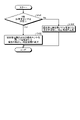
- FIG. 13 is a flowchart showing the operation of the on-vehicle control device 2a according to the second embodiment.
- the on-vehicle control device 2a determines whether or not the two-axis acceleration sensor 1a is normal (step S121).
- the operation of step S102 and step S103 is the same as the operation of step S102 and step S103 of the flowchart in the case of the first embodiment shown in FIG.
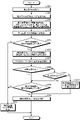
- FIG. 14 is a flowchart showing an operation of determining whether or not the two-axis acceleration sensor 1a is normal in the on-vehicle control device 2a according to the second embodiment.
- the flowchart shown in FIG. 14 shows the details of the operation of step S121 of the flowchart shown in FIG.
- the operation from step S201 to step S204 is the same as the operation from step S201 to step S204 in the flowchart of the first embodiment shown in FIG.
- the on-board control device 2a is the train 10 calculated by using the fifth acceleration ( ⁇ _Sen_z) of the second detection axis output from the two-axis acceleration sensor 1a, the gravitational acceleration g, and the gradient value Gx of the train position. It is determined whether or not the sixth acceleration (g ⁇ ⁇ (1-G ⁇ 2 )) in the direction perpendicular to the floor surface matches (step S221). The on-board control device 2a calculates the difference between the fifth acceleration ( ⁇ _Sen_z) and the sixth acceleration (g ⁇ ⁇ (1-Gx 2 )) in consideration of the measurement error of the two-axis acceleration sensor 1a. If the absolute value of the difference is within the second threshold THRE2, it may be determined that they match.
- the second threshold value is a predetermined threshold value in consideration of the measurement error of the 2-axis acceleration sensor 1a and the like, and is stored by, for example, the storage unit 22.
- the on-vehicle control device 2a determines in step S221 regardless of the traveling state of the train 10a.
- the detection unit and the common portion of the second detection axis are normal in the two-axis acceleration sensor 1a. It is determined that there is (step S222).
- FIG. 15 is a diagram showing a configuration example of the two-axis acceleration sensor 1a included in the train 10a according to the second embodiment.
- the 2-axis accelerometer 1a includes detection units 30 and 40 and a common unit 50.
- the detection unit 30 is a detection unit of a first detection axis including an x-axis acceleration sensor unit 31, an A / D (Analog to Digital) converter 32, and a filter unit 33.
- the detection unit 40 is a detection unit of a second detection axis including a z-axis acceleration sensor unit 41, an A / D converter 42, and a filter unit 43.
- the common unit 50 includes a power supply unit 51, a control logic unit 52, a FIFO (First In First Out) 53, a serial I / O (Input / Output) unit 54, and a transmission cable 55.
- the common unit 50 is configured to be commonly used by the detection units 30 and 40.
- the on-board control device 2a could only diagnose the failure of the acceleration sensor 1 of the first embodiment when the train 10 was stopped or coasting, but in step S222, the second axis acceleration sensor 1a was the second. Failure diagnosis of the detection unit 40 and the common unit 50, which are the detection units of the detection axis, is always possible.
- the on-board control device 2a is the train 10a calculated by using the fifth acceleration of the second detection axis output from the two-axis acceleration sensor 1a, the gravitational acceleration g, and the gradient value of the train position. Based on the comparison result comparing with the sixth acceleration in the direction perpendicular to the floor surface, the soundness of the detection unit 40 and the common unit 50 provided in the 2-axis acceleration sensor 1a is determined regardless of the running state of the train 10a. Can be diagnosed.
- step S205 to step S208 are the same as the operations from step S205 to step S208 in the flowchart of the first embodiment shown in FIG.
- step S221: No the on-board control device 2a determines that the two-axis acceleration sensor 1a is abnormal (step S223).
- step S208: No the on-board control device 2a determines that the two-axis acceleration sensor 1a is abnormal (step S223).
- step S208: Yes the on-board control device 2a determines that the two-axis acceleration sensor 1a is normal (step S224).
- step S206 When the train 10a is not coasting (step S206: No) and the train 10a is not stopped (step S207: No), the on-board control device 2a determines the soundness of the two-axis acceleration sensor 1a in this operation. Without making a diagnosis, the 2-axis accelerometer 1a is regarded as normal (step S225).
- the on-board control device 2a mounted on the train 10a does not use a vibration source that gives vibration to the two-axis acceleration sensor 1a, and the running state of the train 10a. Regardless of this, it can be determined whether or not the detection unit 40 and the common unit 50 of the second detection axis of the 2-axis acceleration sensor 1a are normal.
- the configuration shown in the above embodiments is an example, and can be combined with another known technique, can be combined with each other, and does not deviate from the gist. It is also possible to omit or change a part of the configuration.
Landscapes
- Engineering & Computer Science (AREA)
- General Physics & Mathematics (AREA)
- Physics & Mathematics (AREA)
- Mechanical Engineering (AREA)
- Sustainable Energy (AREA)
- Transportation (AREA)
- Power Engineering (AREA)
- Life Sciences & Earth Sciences (AREA)
- Sustainable Development (AREA)
- Radar, Positioning & Navigation (AREA)
- Remote Sensing (AREA)
- Electric Propulsion And Braking For Vehicles (AREA)
- Train Traffic Observation, Control, And Security (AREA)
Abstract
Description
図1は、実施の形態1に係る列車制御システム100の構成例を示す図である。列車制御システム100は、列車10と、地上子11と、地上無線装置12と、地上装置13と、を備える。列車10は、加速度センサ1と、車上制御装置2と、車上子3と、マスタコントローラ4と、速度発電機5と、車上無線装置6と、車上アンテナ7と、ブレーキ装置8と、推進制御装置9と、を備える。 Embodiment 1.
FIG. 1 is a diagram showing a configuration example of the
実施の形態2では、列車が2軸加速度センサを備える場合について説明する。 Embodiment 2.
In the second embodiment, a case where the train includes a two-axis accelerometer will be described.
Claims (8)
- 列車に搭載される車上制御装置であって、
前記列車の車輪の回転数に対応したパルスを出力する速度発電機、地上子から前記地上子の識別情報を含む電文を受信する車上子、検知軸が前記列車の進行方向に合わせて設置された加速度センサ、およびマスタコントローラと通信可能な通信部と、
前記列車が走行する路線の各位置における勾配値の情報を記憶する記憶部と、
前記車上子および前記速度発電機から取得した情報を用いて前記列車の列車位置を特定し、前記マスタコントローラから取得した情報から前記列車の走行状態を判定し、前記列車が惰行時または停車時において、前記加速度センサから出力される前記列車の第1の加速度と、重力加速度および前記列車位置の勾配値を用いて算出した前記列車の進行方向の第2の加速度とを比較した比較結果に基づいて、前記加速度センサの健全性を診断する制御部と、
を備えることを特徴とする車上制御装置。 It is an on-board control device mounted on a train.
A speed generator that outputs a pulse corresponding to the number of rotations of the wheels of the train, an on-board element that receives a message including identification information of the ground element from the ground element, and a detection shaft are installed according to the traveling direction of the train. With the accelerometer and the communication unit that can communicate with the master controller,
A storage unit that stores information on the gradient value at each position of the line on which the train travels, and a storage unit.
The train position of the train is specified using the information acquired from the on-board child and the speed generator, the running state of the train is determined from the information acquired from the master controller, and the train is coasting or stopped. Based on the comparison result of comparing the first acceleration of the train output from the acceleration sensor with the second acceleration in the traveling direction of the train calculated by using the gravity acceleration and the gradient value of the train position. And the control unit that diagnoses the soundness of the acceleration sensor,
An on-board control device characterized by being equipped with. - 前記制御部は、前記加速度センサが正常な場合、前記速度発電機から出力される前記パルスから算出した前記列車の第3の加速度と前記第1の加速度との差分を算出し、前記差分と空転を検出するための閾値とを比較した比較結果に基づいて前記空転の有無を判定し、前記差分と滑走を検出するための閾値とを比較した比較結果に基づいて前記滑走の有無を判定する、
ことを特徴とする請求項1に記載の車上制御装置。 When the acceleration sensor is normal, the control unit calculates the difference between the third acceleration of the train and the first acceleration calculated from the pulse output from the speed generator, and the difference and idling. The presence or absence of the slip is determined based on the comparison result comparing with the threshold value for detecting the slip, and the presence or absence of the slip is determined based on the comparison result comparing the difference with the threshold value for detecting the slip.
The on-vehicle control device according to claim 1. - 前記制御部は、前記加速度センサが異常な場合、前記速度発電機の単位時間当たりの前記パルスの増分から前記列車の第4の加速度を算出し、前記第4の加速度と空転を検出するための閾値とを比較した比較結果に基づいて前記空転の有無を判定し、前記第4の加速度と滑走を検出するための閾値とを比較した比較結果に基づいて前記滑走の有無を判定する、
ことを特徴とする請求項1に記載の車上制御装置。 When the acceleration sensor is abnormal, the control unit calculates the fourth acceleration of the train from the increment of the pulse per unit time of the speed generator, and detects the fourth acceleration and idling. The presence or absence of the slip is determined based on the comparison result comparing with the threshold value, and the presence or absence of the slip is determined based on the comparison result comparing the fourth acceleration with the threshold value for detecting the gliding.
The on-vehicle control device according to claim 1. - 前記加速度センサは、前記検知軸である第1の検知軸と、前記第1の検知軸と直交し、前記列車の床面に対して垂直方向に合わせて設置された第2の検知軸と、を備え、
前記制御部は、前記加速度センサから出力される前記第2の検知軸についての第5の加速度と、前記重力加速度および前記列車位置の勾配値を用いて算出した前記列車の床面に対して垂直方向の第6の加速度とを比較した比較結果に基づいて、前記列車の走行状態に関わらず、前記加速度センサが備える前記第1の検知軸および前記第2の検知軸の共通部の健全性を診断する、
ことを特徴とする請求項1から3のいずれか1つに記載の車上制御装置。 The accelerometer has a first detection axis, which is the detection axis, and a second detection axis, which is orthogonal to the first detection axis and is installed so as to be perpendicular to the floor surface of the train. Equipped with
The control unit is perpendicular to the floor surface of the train calculated by using the fifth acceleration of the second detection axis output from the acceleration sensor, the gravitational acceleration, and the gradient value of the train position. Based on the comparison result comparing with the sixth acceleration in the direction, the soundness of the common part of the first detection axis and the second detection axis included in the acceleration sensor is determined regardless of the running state of the train. Diagnose,
The on-vehicle control device according to any one of claims 1 to 3, wherein the on-vehicle control device is characterized. - 列車に搭載される車上制御装置の加速度センサ診断方法であって、
前記車上制御装置が、
前記列車の車輪の回転数に対応したパルスを出力する速度発電機、地上子から前記地上子の識別情報を含む電文を受信する車上子、検知軸が前記列車の進行方向に合わせて設置された加速度センサ、およびマスタコントローラと通信可能な通信部と、
前記列車が走行する路線の各位置における勾配値の情報を記憶する記憶部と、
制御部と、
を備え、
前記制御部が、前記車上子および前記速度発電機から取得した情報を用いて前記列車の列車位置を特定する第1のステップと、
前記制御部が、前記マスタコントローラから取得した情報から前記列車の走行状態を判定する第2のステップと、
前記制御部が、前記列車が惰行時または停車時において、前記加速度センサから出力される前記列車の第1の加速度と、重力加速度および前記列車位置の勾配値を用いて算出した前記列車の進行方向の第2の加速度とを比較した比較結果に基づいて、前記加速度センサの健全性を診断する第3のステップと、
を含むことを特徴とする加速度センサ診断方法。 It is a method of diagnosing the acceleration sensor of the on-board control device mounted on the train.
The on-board control device
A speed generator that outputs a pulse corresponding to the number of rotations of the wheels of the train, an on-board element that receives a message including identification information of the ground element from the ground element, and a detection shaft are installed according to the traveling direction of the train. With the accelerometer and the communication unit that can communicate with the master controller,
A storage unit that stores information on the gradient value at each position of the line on which the train travels, and a storage unit.
Control unit and
Equipped with
The first step in which the control unit identifies the train position of the train by using the information acquired from the on-board element and the speed generator.
A second step in which the control unit determines the running state of the train from the information acquired from the master controller, and
The traveling direction of the train calculated by the control unit using the first acceleration of the train output from the acceleration sensor, the gravitational acceleration, and the gradient value of the train position when the train is coasting or stopped. Based on the comparison result comparing with the second acceleration of the above, the third step of diagnosing the integrity of the acceleration sensor and
Accelerometer diagnostic method comprising: - 前記第3のステップにおいて、前記制御部は、前記加速度センサが正常な場合、前記速度発電機から出力される前記パルスから算出した前記列車の第3の加速度と前記第1の加速度との差分を算出し、前記差分と空転を検出するための閾値とを比較した比較結果に基づいて前記空転の有無を判定し、前記差分と滑走を検出するための閾値とを比較した比較結果に基づいて前記滑走の有無を判定する、
ことを特徴とする請求項5に記載の加速度センサ診断方法。 In the third step, when the acceleration sensor is normal, the control unit determines the difference between the third acceleration of the train and the first acceleration calculated from the pulse output from the speed generator. The presence or absence of the slip is determined based on the calculation result of comparing the difference with the threshold for detecting the slip, and the comparison result comparing the difference with the threshold for detecting the slip is described. Judging the presence or absence of gliding,
The acceleration sensor diagnostic method according to claim 5, wherein the method is characterized by the above. - 前記第3のステップにおいて、前記制御部は、前記加速度センサが異常な場合、前記速度発電機の単位時間当たりの前記パルスの増分から前記列車の第4の加速度を算出し、前記第4の加速度と空転を検出するための閾値とを比較した比較結果に基づいて前記空転の有無を判定し、前記第4の加速度と滑走を検出するための閾値とを比較した比較結果に基づいて前記滑走の有無を判定する、
ことを特徴とする請求項5に記載の加速度センサ診断方法。 In the third step, when the acceleration sensor is abnormal, the control unit calculates the fourth acceleration of the train from the increment of the pulse per unit time of the speed generator, and the fourth acceleration. The presence or absence of the slip is determined based on the comparison result comparing the threshold for detecting the slip and the slip, and the slip is performed based on the comparison result comparing the fourth acceleration and the threshold for detecting the slip. Judge the presence or absence,
The acceleration sensor diagnostic method according to claim 5, wherein the method is characterized by the above. - 前記加速度センサは、前記検知軸である第1の検知軸と、前記第1の検知軸と直交し、前記列車の床面に対して垂直方向に合わせて設置された第2の検知軸と、を備え、
前記第3のステップにおいて、前記制御部は、前記加速度センサから出力される前記第2の検知軸についての第5の加速度と、前記重力加速度および前記列車位置の勾配値を用いて算出した前記列車の床面に対して垂直方向の第6の加速度とを比較した比較結果に基づいて、前記列車の走行状態に関わらず、前記加速度センサが備える前記第1の検知軸および前記第2の検知軸の共通部の健全性を診断する、
ことを特徴とする請求項5から7のいずれか1つに記載の加速度センサ診断方法。 The accelerometer has a first detection axis, which is the detection axis, and a second detection axis, which is orthogonal to the first detection axis and is installed so as to be perpendicular to the floor surface of the train. Equipped with
In the third step, the control unit uses the fifth acceleration of the second detection axis output from the acceleration sensor, the gravitational acceleration, and the gradient value of the train position to calculate the train. Based on the comparison result of comparing the sixth acceleration in the direction perpendicular to the floor surface of the train, the first detection axis and the second detection axis included in the acceleration sensor are provided regardless of the running state of the train. Diagnose the health of the common parts of
The acceleration sensor diagnostic method according to any one of claims 5 to 7, wherein the method is characterized by that.
Priority Applications (4)
| Application Number | Priority Date | Filing Date | Title |
|---|---|---|---|
| JP2022564859A JP7345682B2 (en) | 2020-11-24 | 2020-11-24 | On-vehicle control device and acceleration sensor diagnostic method |
| US18/252,748 US20240003937A1 (en) | 2020-11-24 | 2020-11-24 | On-board control device and acceleration sensor diagnosis method |
| PCT/JP2020/043698 WO2022113177A1 (en) | 2020-11-24 | 2020-11-24 | On-board control device and acceleration sensor diagnostic method |
| DE112020007798.5T DE112020007798T5 (en) | 2020-11-24 | 2020-11-24 | ON-BOARD CONTROL DEVICE AND ACCELERATION SENSOR DIAGNOSTIC METHOD |
Applications Claiming Priority (1)
| Application Number | Priority Date | Filing Date | Title |
|---|---|---|---|
| PCT/JP2020/043698 WO2022113177A1 (en) | 2020-11-24 | 2020-11-24 | On-board control device and acceleration sensor diagnostic method |
Publications (1)
| Publication Number | Publication Date |
|---|---|
| WO2022113177A1 true WO2022113177A1 (en) | 2022-06-02 |
Family
ID=81754086
Family Applications (1)
| Application Number | Title | Priority Date | Filing Date |
|---|---|---|---|
| PCT/JP2020/043698 WO2022113177A1 (en) | 2020-11-24 | 2020-11-24 | On-board control device and acceleration sensor diagnostic method |
Country Status (4)
| Country | Link |
|---|---|
| US (1) | US20240003937A1 (en) |
| JP (1) | JP7345682B2 (en) |
| DE (1) | DE112020007798T5 (en) |
| WO (1) | WO2022113177A1 (en) |
Citations (4)
| Publication number | Priority date | Publication date | Assignee | Title |
|---|---|---|---|---|
| JPS6277803A (en) * | 1985-09-30 | 1987-04-10 | Toshiba Corp | Speed detecting device for vehicle |
| JP2015137078A (en) * | 2014-01-24 | 2015-07-30 | 三菱電機株式会社 | train radio system |
| JP2017147825A (en) * | 2016-02-16 | 2017-08-24 | 株式会社東芝 | Train speed and position calculation device, train operation support device, and train operation control device |
| JP2019050691A (en) * | 2017-09-12 | 2019-03-28 | 株式会社日立製作所 | Train position detection system, automatic train control system, train operation support system, and train obstacle detection system |
Family Cites Families (2)
| Publication number | Priority date | Publication date | Assignee | Title |
|---|---|---|---|---|
| JP5824650B2 (en) | 2010-09-30 | 2015-11-25 | パナソニックIpマネジメント株式会社 | Regenerative braking control device for vehicle |
| JP2016137731A (en) | 2015-01-26 | 2016-08-04 | 株式会社日立製作所 | Vehicle control system, on-train device, and ground device |
-
2020
- 2020-11-24 US US18/252,748 patent/US20240003937A1/en active Pending
- 2020-11-24 WO PCT/JP2020/043698 patent/WO2022113177A1/en active Application Filing
- 2020-11-24 JP JP2022564859A patent/JP7345682B2/en active Active
- 2020-11-24 DE DE112020007798.5T patent/DE112020007798T5/en active Pending
Patent Citations (4)
| Publication number | Priority date | Publication date | Assignee | Title |
|---|---|---|---|---|
| JPS6277803A (en) * | 1985-09-30 | 1987-04-10 | Toshiba Corp | Speed detecting device for vehicle |
| JP2015137078A (en) * | 2014-01-24 | 2015-07-30 | 三菱電機株式会社 | train radio system |
| JP2017147825A (en) * | 2016-02-16 | 2017-08-24 | 株式会社東芝 | Train speed and position calculation device, train operation support device, and train operation control device |
| JP2019050691A (en) * | 2017-09-12 | 2019-03-28 | 株式会社日立製作所 | Train position detection system, automatic train control system, train operation support system, and train obstacle detection system |
Also Published As
| Publication number | Publication date |
|---|---|
| US20240003937A1 (en) | 2024-01-04 |
| JPWO2022113177A1 (en) | 2022-06-02 |
| DE112020007798T5 (en) | 2023-09-28 |
| JP7345682B2 (en) | 2023-09-15 |
Similar Documents
| Publication | Publication Date | Title |
|---|---|---|
| US9308926B2 (en) | Position control system | |
| KR101157752B1 (en) | Device for measuring the movement of a self-guided vehicle | |
| ES2718065T3 (en) | Railway vehicle | |
| CN111452837B (en) | Automatic train protection method and system | |
| KR101157756B1 (en) | Device for measuring the movement of a self-guiding vehicle | |
| JP6092245B2 (en) | Method and apparatus for determining the mounting position of a sensor module in a vehicle, and vehicle equipped with the apparatus | |
| CN105555637B (en) | Vehicle positioning system and its application method | |
| WO2018155489A1 (en) | Vehicle control device, vehicle control method, and program | |
| CN109153333B (en) | Vehicle-mounted device and train occupation range calculation method | |
| JP4781331B2 (en) | Train speed control device | |
| JP2018117478A (en) | Train separation detection system and method therefor | |
| WO2022113177A1 (en) | On-board control device and acceleration sensor diagnostic method | |
| JP7089063B2 (en) | Position detector and method | |
| JP3676131B2 (en) | Train fixed point stop automatic operation method | |
| CN113548090B (en) | Method and device for adjusting accurate parking control parameters of train automatic driving | |
| JP2003004758A (en) | Vehicle speed measuring apparatus and method | |
| US20200406898A1 (en) | Friction coefficient estimation apparatus, vehicle control apparatus, and friction coefficient estimation method | |
| AU2021375837B2 (en) | Vehicle speed calculation device and vehicle speed calculation method | |
| JPWO2022113177A5 (en) | ||
| CN115782869A (en) | Vehicle control system and vehicle control method | |
| WO2019240017A1 (en) | Train control device | |
| JP3632008B2 (en) | Autonomous driving vehicle | |
| JP2023141304A (en) | Train operation control device, train operation control method, and program | |
| JPH0781533A (en) | Air brake controller |
Legal Events
| Date | Code | Title | Description |
|---|---|---|---|
| 121 | Ep: the epo has been informed by wipo that ep was designated in this application |
Ref document number: 20963442 Country of ref document: EP Kind code of ref document: A1 |
|
| ENP | Entry into the national phase |
Ref document number: 2022564859 Country of ref document: JP Kind code of ref document: A |
|
| WWE | Wipo information: entry into national phase |
Ref document number: 202327024081 Country of ref document: IN |
|
| WWE | Wipo information: entry into national phase |
Ref document number: 18252748 Country of ref document: US |
|
| WWE | Wipo information: entry into national phase |
Ref document number: 112020007798 Country of ref document: DE |
|
| 122 | Ep: pct application non-entry in european phase |
Ref document number: 20963442 Country of ref document: EP Kind code of ref document: A1 |