WO2022112350A1 - Procédé de stérilisation du réseau de soufflage d'une machine de formage de récipients thermoplastiques - Google Patents
Procédé de stérilisation du réseau de soufflage d'une machine de formage de récipients thermoplastiques Download PDFInfo
- Publication number
- WO2022112350A1 WO2022112350A1 PCT/EP2021/082863 EP2021082863W WO2022112350A1 WO 2022112350 A1 WO2022112350 A1 WO 2022112350A1 EP 2021082863 W EP2021082863 W EP 2021082863W WO 2022112350 A1 WO2022112350 A1 WO 2022112350A1
- Authority
- WO
- WIPO (PCT)
- Prior art keywords
- blowing
- sterilizing
- network
- gas
- vapor
- Prior art date
- Legal status (The legal status is an assumption and is not a legal conclusion. Google has not performed a legal analysis and makes no representation as to the accuracy of the status listed.)
- Ceased
Links
Images




Classifications
-
- B—PERFORMING OPERATIONS; TRANSPORTING
- B29—WORKING OF PLASTICS; WORKING OF SUBSTANCES IN A PLASTIC STATE IN GENERAL
- B29C—SHAPING OR JOINING OF PLASTICS; SHAPING OF MATERIAL IN A PLASTIC STATE, NOT OTHERWISE PROVIDED FOR; AFTER-TREATMENT OF THE SHAPED PRODUCTS, e.g. REPAIRING
- B29C49/00—Blow-moulding, i.e. blowing a preform or parison to a desired shape within a mould; Apparatus therefor
- B29C49/42—Component parts, details or accessories; Auxiliary operations
- B29C49/46—Component parts, details or accessories; Auxiliary operations characterised by using particular environment or blow fluids other than air
-
- B—PERFORMING OPERATIONS; TRANSPORTING
- B29—WORKING OF PLASTICS; WORKING OF SUBSTANCES IN A PLASTIC STATE IN GENERAL
- B29C—SHAPING OR JOINING OF PLASTICS; SHAPING OF MATERIAL IN A PLASTIC STATE, NOT OTHERWISE PROVIDED FOR; AFTER-TREATMENT OF THE SHAPED PRODUCTS, e.g. REPAIRING
- B29C49/00—Blow-moulding, i.e. blowing a preform or parison to a desired shape within a mould; Apparatus therefor
- B29C49/42—Component parts, details or accessories; Auxiliary operations
- B29C49/4252—Auxiliary operations prior to the blow-moulding operation not otherwise provided for
-
- B—PERFORMING OPERATIONS; TRANSPORTING
- B29—WORKING OF PLASTICS; WORKING OF SUBSTANCES IN A PLASTIC STATE IN GENERAL
- B29C—SHAPING OR JOINING OF PLASTICS; SHAPING OF MATERIAL IN A PLASTIC STATE, NOT OTHERWISE PROVIDED FOR; AFTER-TREATMENT OF THE SHAPED PRODUCTS, e.g. REPAIRING
- B29C49/00—Blow-moulding, i.e. blowing a preform or parison to a desired shape within a mould; Apparatus therefor
- B29C49/42—Component parts, details or accessories; Auxiliary operations
- B29C49/78—Measuring, controlling or regulating
- B29C49/786—Temperature
-
- B—PERFORMING OPERATIONS; TRANSPORTING
- B29—WORKING OF PLASTICS; WORKING OF SUBSTANCES IN A PLASTIC STATE IN GENERAL
- B29C—SHAPING OR JOINING OF PLASTICS; SHAPING OF MATERIAL IN A PLASTIC STATE, NOT OTHERWISE PROVIDED FOR; AFTER-TREATMENT OF THE SHAPED PRODUCTS, e.g. REPAIRING
- B29C49/00—Blow-moulding, i.e. blowing a preform or parison to a desired shape within a mould; Apparatus therefor
- B29C49/28—Blow-moulding apparatus
- B29C49/30—Blow-moulding apparatus having movable moulds or mould parts
- B29C49/36—Blow-moulding apparatus having movable moulds or mould parts rotatable about one axis
-
- B—PERFORMING OPERATIONS; TRANSPORTING
- B29—WORKING OF PLASTICS; WORKING OF SUBSTANCES IN A PLASTIC STATE IN GENERAL
- B29C—SHAPING OR JOINING OF PLASTICS; SHAPING OF MATERIAL IN A PLASTIC STATE, NOT OTHERWISE PROVIDED FOR; AFTER-TREATMENT OF THE SHAPED PRODUCTS, e.g. REPAIRING
- B29C49/00—Blow-moulding, i.e. blowing a preform or parison to a desired shape within a mould; Apparatus therefor
- B29C49/42—Component parts, details or accessories; Auxiliary operations
- B29C49/42403—Purging or cleaning the blow-moulding apparatus
-
- B—PERFORMING OPERATIONS; TRANSPORTING
- B29—WORKING OF PLASTICS; WORKING OF SUBSTANCES IN A PLASTIC STATE IN GENERAL
- B29C—SHAPING OR JOINING OF PLASTICS; SHAPING OF MATERIAL IN A PLASTIC STATE, NOT OTHERWISE PROVIDED FOR; AFTER-TREATMENT OF THE SHAPED PRODUCTS, e.g. REPAIRING
- B29C49/00—Blow-moulding, i.e. blowing a preform or parison to a desired shape within a mould; Apparatus therefor
- B29C49/42—Component parts, details or accessories; Auxiliary operations
- B29C49/42403—Purging or cleaning the blow-moulding apparatus
- B29C49/42405—Sterilizing
-
- B—PERFORMING OPERATIONS; TRANSPORTING
- B29—WORKING OF PLASTICS; WORKING OF SUBSTANCES IN A PLASTIC STATE IN GENERAL
- B29C—SHAPING OR JOINING OF PLASTICS; SHAPING OF MATERIAL IN A PLASTIC STATE, NOT OTHERWISE PROVIDED FOR; AFTER-TREATMENT OF THE SHAPED PRODUCTS, e.g. REPAIRING
- B29C49/00—Blow-moulding, i.e. blowing a preform or parison to a desired shape within a mould; Apparatus therefor
- B29C49/42—Component parts, details or accessories; Auxiliary operations
- B29C49/42407—Procedures for start-up or material change
Definitions
- the invention relates to a method for sterilizing a forming machine for forming containers from preforms of thermoplastic material, the forming machine comprising a blowing network which comprises pipes which connect a controlled source of compressed blowing to at least one blowing nozzle to form the containers by blowing, the forming machine comprising a device for sterilizing the blowing network comprising:
- a container manufacturing facility comprises at least one oven for heating preforms which is associated with a forming machine (also called a “blower") for molding containers from said hot preforms.
- the installation also advantageously comprises a sterilization unit for sterilizing at least the inside of the preforms so as to obtain so-called “sterile” containers.
- a preliminary pre-blowing operation is sometimes carried out which consists of injecting a blowing fluid at a lower pressure, for example at 13 bars, into the preform before proceeding. to the actual blowing operation by means of a high pressure blowing gas as explained previously.
- the air used for blowing is introduced inside the hot preform placed in a mold so that the blowing air comes into direct contact with the inner surface of the container.
- the forming machine comprises a controlled source of blowing air which supplies several blowing nozzles via blowing pipes.
- the internal surface is itself intended to be subsequently in contact with the product which will be packaged in the container.
- the quality of the supply air is therefore an important parameter to be taken into account in the overall control of contamination risks.
- containers manufactured and this in order to be able to guarantee, in particular in the case of agro-food packaging, good preservation of the packaged product, in particular a shelf life, and consumer safety.
- the quality of the compressed air used for blowing is determined by a set of factors, from the quality of the atmospheric air sucked in, which varies according to the environment of the industrial site and its location in relation to polluting sources, to 'the state of the distribution network and/or installation.
- the atmospheric air sucked in and compressed by at least one compressor has, for example, a more or less significant degree of hygrometry, or the humidity promotes corrosion and the development of micro-organisms.
- compressors are, according to their design, particularly the means of lubrication, likely to cause chemical contamination of the air, for example by lubricating oil or even dust. of teflon.
- blowing air which is "sterile", that is that is to say in particular free of micro-organisms.
- the compressed air used for blowing is generally successively filtered by a filtration system comprising different means of gas filtration.
- such an air filtration system intended for blowing comprises for example multiple filtration means which, arranged in series, are intended to deliver sterile air at the outlet.
- first filtration means of the "FFP” type to obtain in particular oil removal, water purification and elimination of dust
- second filtration means of the "AK” type (with coals active) to remove all oil vapors and gaseous hydrocarbons which may also cause an olfactory and taste nuisance
- third "SRF” type filtration means to retain micro-organisms.
- blowing air is likely to be a vector of contamination of the interior of the preform, and therefore of the container, by introducing contaminants therein and very particularly microorganisms (viruses, germs, spores, etc. .).
- Controlling the quality of the compressed air used for blowing is even more important when, in the container manufacturing process, the filling of the containers is carried out in an aseptic environment directly after the molding of the container obtained by blowing or by stretching -blowing of a hot preform.
- the sterilization is generally carried out upstream on the preforms, before their transformation into containers, so that it is then essential to prevent the risks of contamination of the sterilized preforms, like that of the containers manufactured from these preforms.
- the invention aims to sterilize the blowing pipes which are arranged downstream of the filtration means and which lead the sterile blowing air to the blowing nozzles. This notably makes it possible to guarantee that the air remains sterile until it reaches the preforms.
- the sterilization of the blow molding pipes must make it possible to destroy the micro-organisms present in order to prevent their development in the blow molding pipes and thus eliminate the risks of contamination of the preforms.
- a sterilizing gas mixture comprising an oxidizing agent in the gaseous phase in the blow pipes.
- the vapor-phase oxidizing agent is generally formed by evaporation of the liquid-phase oxidizing agent, for example hydrogen peroxide (H2O2).
- Such a sterilizing gas mixture has the disadvantage of condensing on the internal walls of the blowing pipes.
- Contact with the oxidizing agent in the vapor phase eliminates microorganisms without damaging the blowing pipes.
- the drops of condensation comprising the oxidizing agent rapidly damage the internal walls of the pipes by corrosion.
- the invention therefore proposes a solution which makes it possible to avoid the appearance of condensation of the oxidizing agent during the sterilization operation. This would make it possible in particular to be able to use a less expensive metallic material for the manufacture of the blowing ducts.
- the invention relates to a method of sterilizing a forming machine for forming containers from preforms of thermoplastic material, the forming machine comprising a blowing network which comprises pipes which connect a controlled source of compressed blowing gas to at least one blowing nozzle for forming the containers by blowing, the forming machine comprising a device for sterilizing the blowing network comprising:
- the second step of injecting the sterilizing gas mixture is triggered when the coldest point, called the cold point, of the blowing network exposed to the sterilizing gas mixture reaches a treatment temperature which is higher than a condensation temperature of the water vapor and the sterilizing agent vaporized at said cold point, the treatment temperature being lower than the temperature of the hot drying gas taken from the supply branch.
- the treatment temperature is determined so that the ratio, called relative saturation, between the partial pressure of the mixture of steam and sterilizing agent vaporized on the saturated vapor pressure of said mixture at the cold point of the blowing network is within a determined range extending between 70% and 90%.
- the determined range extends between 80% and 90%.
- the treatment temperature is measured by means of a probe arranged at the level of the cold point.
- the relative saturation is measured at the level of the cold point of the blowing network by means of a sensor.
- the temperature, the humidity and the pressure of the drying gas at the level of the feed branch are constant.
- the controlled source of drying gas is controlled at a constant flow rate for the entire duration of the sterilization process.
- the controlled source of sterilizing vapor is controlled at a constant flow rate during the second step of injection of the sterilizing gas mixture of the sterilization process.
- the controlled source of sterilizing vapor has a flow capable of occupying at least an intermediate flow between a zero flow and a maximum flow throughout the sterilization process. .
- the flow rate of sterilizing vapor in the mixing chamber is controlled according to the measurement carried out by the sensor to maintain the relative saturation in the range determined at the level of the cold point. .
- the invention also relates to a forming machine for implementing the method carried out according to the teachings of the invention, the forming machine comprising a blowing network which comprises pipes which connect a controlled source of compressed blowing gas to at least at least one blowing nozzle for forming the containers by blowing, the forming machine comprising a device for sterilizing the blowing network comprising:
- a temperature probe arranged so as to measure the temperature of a pipe of the blowing network in the nozzle or close to the nozzle.
- upstream and downstream are used to describe the direction of flow of a gas in the pipes.
- the forming machine 10 has a fixed part 12 with respect to the ground and a rotating part 14 which is mounted on a rotating carousel (not shown).
- the rotating part 14 comprises several molding stations 16 which are mounted on the carousel. This arrangement makes it possible to produce containers in large series. As depicted at , each molding station 16 comprises a mold 18 which is intended to receive a preform and which has an imprint of the container to be produced. Each molding station 16 also comprises a blow nozzle 20 which is shaped so as to blow a pressurized forming gas into the preform received in the mold 18. This is for example a nozzle 20 which comprises a nozzle 22 bell-shaped which is intended to cover a neck of the preform received in the mold 18.
- the fixed part 12 includes a controlled source 24 of compressed blowing gas.
- the blowing gas is for example compressed to approximately 40 bars.
- the blowing gas is for example air.
- the controlled source 24 of blowing gas is connected to the nozzles 20 of each molding station 16 by a network of blowing pipes, referred to as the blowing network 26 in the following description and in the claims.
- the pipes of the blowing network 26 are here made of a material which is likely to be oxidized quickly on contact with an oxidizing agent in liquid form, such as hydrogen peroxide or acetic acid, unlike pipes made of stainless material.
- the blowing network 26 comprises a main supply pipe 28 which connects the controlled source 24 of blowing gas to a rotating joint 30 which makes it possible to form the interface between the fixed part 12 and the rotating part 14 .
- the blowing network 26 also comprises at least one distribution ramp 32 which belongs to the rotating part 14 and which is connected to the main supply pipe 28 via the rotating joint 30.
- the distribution ramp 32 is connected to each of the molding stations 16 by means of pipes 34 associated with distribution.
- a filtration unit 35 for example an “SRF” type filter, is interposed in the main supply pipe 28 .
- the blowing network 26 also comprises a high pressure blowing pipe 36 which is connected to the distribution pipe 34 associated with the nozzle 20.
- a two-way blowing valve 38 is interposed in the pipe. 36 high pressure blower.
- the blow-off valve 38 is controlled alternately between an open position and a closed position.
- the blowing network 26 also includes a low-pressure pre-blowing pipe 40 which connects the distribution pipe 34 associated with the nozzle 20 in parallel with the high-pressure blowing pipe 36 .
- the low pressure blowing line 40 comprises a member 42 for regulating the pressure of the blowing gas in order to lower the pressure thereof, for example down to approximately 13 bars.
- a two-way pre-blowing valve 44 is interposed in the low-pressure blowing pipe 40 . The pre-blowing valve 44 is controlled alternately between an open position and a closed position.
- the forming machine 10 also includes a device 46 for sterilizing the network 26 for blowing.
- the sterilization device 46 comprises a controlled source 48 of a hot drying gas under pressure, for example air.
- the controlled source 48 of drying gas is separate from the controlled source 24 of blowing gas.
- the controlled source 48 of drying gas is connected to the blowing network 26 in a supply branch 49 via a pipe 50 for sterilization.
- the controlled source 48 of drying gas is here arranged on the fixed part 12 of the machine 10 for forming.
- the feed branch 49 is preferably also arranged on the fixed part 12 of the forming machine 10, upstream of the rotary joint 30.
- the feed branch 49 is here arranged in the main blow pipe 28 .
- the supply branch 49 is more particularly arranged upstream of the filter unit 35 .
- the feed branch is arranged downstream but close to the filtration unit. In this case, it is preferable to provide additional sterilization means for the sterilization member.
- the controlled source 48 of drying gas comprises a source 52 of pressurized gas, for example air, which supplies the conduit 50 for sterilization.
- the controlled source 48 of drying gas further includes a filter 54 to ensure that the drying gas contains no impurities, a member 56 for regulating the pressure, and a member 58 for heating the drying gas to a determined temperature.
- the temperature "Tg" of the hot drying gas is for example about 180°C.
- the controlled source 48 of drying gas further comprises a valve 60 for regulating the flow of drying gas.
- the control valve 60 is here controlled in a closed position in which the flow of drying gas is zero or in an open position in which the drying gas is delivered with a constant flow.
- the sterilization device 46 also includes a controlled source 62 of sterilizing vapor. As depicted at , it comprises a reservoir 64 of sterilizing liquid comprising an oxidizing agent.
- the oxidizing agent is for example hydrogen peroxide (H2O2) or peracetic acid.
- the sterilizing liquid is for example formed from an aqueous solution comprising a determined concentration of oxidizing agent, for example a solution of hydrogen peroxide diluted to 25% in water.
- the controlled source 62 of sterilant vapor also comprises an evaporator 66 in which sterilant vapor is produced by total evaporation of the sterilant liquid supplied by the reservoir 64 of sterilant liquid via an injection pipe 68 .
- the evaporator 66 comprises a member 69 heating to a sufficient temperature to allow the instantaneous evaporation of the sterilizing liquid.
- the heating member 69 is arranged in a chamber of the evaporator 66.
- the sterilizing vapor thus comprises vaporized oxidizing agent and water vapor in well-defined proportions.
- the controlled source 62 of sterilizing vapor further comprises a device 72 for distributing the sterilizing liquid which is interposed between the reservoir 64 of sterilizing liquid and the evaporator 66. This is a device 72 for distributing with adjustable flow rate.
- the evaporator chamber 66 here forms a chamber 70 for mixing the sterilizing vapor with the drying gas to form a sterilizing gas mixture having a partial pressure of sterilizing vapor determined as a function of the mass flow rate of drying gas and the mass flow rate sterilizing steam.
- the mixing chamber 70 is interposed in the pipe 50 for sterilization.
- the mixing chamber 70 being here formed directly by the evaporator chamber 66, the mass flow rate of sterilant vapor is understood as being the mass of sterilant vapor produced by evaporation in the evaporator 66 per unit time.
- the mixing chamber is separate from the evaporator chamber.
- the mixing chamber is then arranged downstream of the evaporator in the direction of flow of the sterilizing vapor.
- the sterilization device 46 also includes a flow control valve 74 which is interposed in the sterilization pipe 50 downstream of the mixing chamber 70.
- the regulation valve 74 is here controlled either in a closed position in which it prohibits the passage of any gas towards the network 26 of blowing, or in an open position.
- the forming machine 10 is capable of operating according to a production mode in which the sterilization device 46 is controlled so as not to emit either sterilizing steam or drying gas into the blowing network 26 .
- the controlled source 24 of blowing gas is controlled so as to inject blowing gas into the network 26 of blowing.
- the blow valve 38 and the pre-blowing valve 44 of each molding station 16 are controlled according to the position of said molding station 16 with respect to the fixed part 12 to alternately blow low pressure blowing gas then high pressure blowing gas to allow the container to be formed from a preform.
- the forming machine 10 is also capable of operating according to a sterilization mode which can only be implemented when the production mode is deactivated.
- the sterilization mode is for example activated during a change of container format and/or even at regular time intervals to prevent the development of germs in the network 26 of blowing.
- the sterilization mode is advantageously activated before any production start of the forming machine 10 .
- the mold is empty, that is to say it does not include any preform.
- the forming machine 10 When operating in sterilization mode, the forming machine 10 implements a sterilization process which is shown in .
- a condensation temperature "Td” of a mixture of water vapor and vaporized sterilizing agent is defined, for determined respective molar concentrations and for a determined total pressure of the sterilizing gas mixture, as being the temperature below which water vapor and/or vaporized sterilant begins to condense.
- the condensation temperature "Td” is for example determined by phase diagrams or charts which indicate the condensation temperature "Td” as a function of the pressure and/or as a function of the molar concentration of sterilizing agent vaporized in the mixture. sterilizing gas.
- This parameter is generally given by the sterilizing agent supplier when the product is delivered. It is also possible to find this parameter or to deduce it easily from works well known to those skilled in the art such as "Hydrogen Peroxide" by Schumb et al. dating from 1955.
- the partial pressure of vaporized sterilizing agent in the sterilizing gas mixture is also defined as being the pressure that said vaporized sterilizing agent alone would have. This partial pressure depends in particular on the ambient temperature and on the molar concentration of vaporized sterilizing agent present in the sterilizing gas mixture.
- the partial pressure of water vapor in the sterilizing gas mixture is also defined as being the pressure that water vapor alone would have. This partial pressure depends in particular on the ambient temperature and on the molar concentration of water vapor present in the sterilizing gas mixture.
- the molar concentration can be defined from the mass concentration or the volume concentration of sterilizing agent.
- Saturating vapor pressure is also defined as being the partial pressure of a gas component in a sterilizing gas mixture from which said component begins to condense.
- the saturation vapor pressure increases with ambient temperature.
- the sterilizing gaseous mixture may contain a greater concentration of said gaseous component before reaching the saturation vapor pressure compared to a colder atmosphere, under the same pressure conditions.
- the relative saturation "RS" of the sterilizing gas mixture is defined as being the ratio between the sum of the partial pressures of sterilizing agent in the vapor state and of water vapor relative to the saturated vapor pressure of the steam. water and the oxidizing agent vaporized from the sterilizing gas mixture.
- the relative saturation "RS” is here expressed as a percentage, the temperature conditions being determined. Thus, as long as the relative "RS" saturation is less than 100%, no condensation appears in the sterilizing gas mixture. When the relative "RS” saturation reaches 100%, the water and/or the oxidizing agent begin to condense.
- the relative "RS" saturation of the mixture of vaporized sterilizing agent and water vapor is, for example, determined by phase diagrams or charts which indicate the relative "RS" saturation as a function of the pressure and/or as a function of ambient temperature and/or depending on the molar concentration of sterilizing agent vaporized in the sterilizing gas mixture.
- the relative humidity of the drying gas is defined as being the partial pressure of water vapor over the saturation vapor pressure of the water vapor of the drying gas.
- certain parameters are constant throughout the sterilization process such as the temperature "Tg", the relative humidity and the pressure of the drying gas at the level of the branch 49 d 'feed.
- the flow rate of the controlled source 48 of drying gas is also constant during all the steps of the sterilization process.
- a setpoint for the flow rate of sterilizing steam is determined so as to guarantee satisfactory sterilization of the network 26 for blowing.
- the flow setpoint is for example approximately 0.19 kg/h for a forming machine 10 comprising six stations or else approximately 1.9 kg/h for a forming machine 10 comprising thirty stations.
- This setpoint is for example a function of the length of the network 26 of blowing.
- a duration "d" of exposure of the blowing network 26 to the sterilizing gas mixture is also determined.
- the duration of the sterilization process is for example approximately 30 minutes, each of the three stages, as described below, lasting approximately 10 minutes.
- the sterilizing vapor flow rate setpoint and the duration "d" of exposure are here fixed beforehand. These are, for example, constant values which are determined experimentally or by calculation as a function of characteristics of the forming machine 10, such as the number of molding stations 16 .
- the method according to the invention proposes on the other hand to act on the temperature of the network 26 of blowing to avoid the condensation of the sterilizing vapor in the pipes of the network 26 of blowing.
- blowing valves 38 and the pre-blowing valves 44 for the entire duration of the sterilization process as shown in .
- the controlled source 24 of blowing gas is controlled in the closed position for the duration of the sterilization process.
- the method comprises a first step "E1" of heating the pipes of the blowing network 26.
- this first step "E1” only the hot drying gas under pressure is injected into the blowing network 26 with the determined flow rate.
- the drying gas thus heats each pipe of the blowing network 26 at least to a treatment temperature "Ti" by flow in one direction from the supply branch 49 to the nozzle 20.
- the method also includes a second step “E2" of injecting the sterilizing gas mixture into the blowing pipes, which is triggered at the end of the first step "E1" of heating.
- the device 72 for distributing the sterilizing liquid is controlled to inject the sterilizing liquid with a flow rate corresponding to the sterilizing vapor flow rate setpoint.
- the vaporized oxidizing agent present in the sterilizing gas mixture sterilizes the pipes of the blowing network 26 by direct contact.
- the sterilizing gas mixture flows in one direction from the supply branch 49 to the nozzle 20.
- a pipe (not shown) for suction of the sterilizing gas mixture which is arranged downstream of the nozzle 20 or which is connected to the nozzle close to the nozzle 22 or even at the mold to allow the sterilizing gas mixture comprising the sterilizing agent to be evacuated after it has passed through the network 26 for blowing.
- a third and last step “E3" of aeration is triggered when the duration "d" of exposure is reached, as indicated by the condition "C3".
- the device 72 for dispensing the sterilizing liquid is then closed to interrupt the production of sterilizing vapor.
- the flow of drying gas is maintained. The drying gas therefore continues to circulate, alone, in the pipes of the blowing network 26 for the time necessary to evacuate the residues of sterilizing vapor. The method is then terminated, as indicated by the reference "S2".
- the purpose of the first heating step “E1" is to heat the pipes of the blowing network 26, that is to say the internal walls forming said pipes, to a treatment temperature "Ti" higher than the temperature "Td". condensation to ensure that the sterilizing vapor will not condense in contact with the pipes of the network 26 of blowing.
- the second step “E2" of injecting the sterilizing gas mixture is triggered before all the pipes of the blowing network 26 are heated uniformly. Due to its heterogeneous heating at the start of the process, the blowing network 26 therefore has a section of pipe, called “cold point 75”, which is colder than the rest of the pipes of the blowing network 26.
- the second step “E2" of injection of the sterilizing gas mixture is more particularly triggered when the cold point 75 of the blowing network 26 exposed to the sterilizing gas mixture reaches the treatment temperature "Ti", the treatment temperature "Ti” being lower at the temperature "Tg" of the hot drying gas taken at the supply branch 49.
- This cold point 75 is generally located in the nozzle 20 or close to the nozzle 20, for example directly upstream of the nozzle 20, or downstream of the nozzle 20 in the mold 18.
- the pipes of the network 26 of blowing are at a cold temperature relative to the treatment temperature "Ti" at the start of the process.
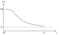
- the hot drying gas will initially exchange calories with the pipes of the blowing network 26 located near the supply branch 49, so that, as indicated in , a decreasing temperature gradient will be established as a function of the length "L" of pipes traveled from upstream to downstream in the blowing network 26 from the supply branch 49, indicated by the point "L0", towards the nozzles 20, indicated by the point "L1".
- the blowing network 26 is not heated uniformly, but according to a decreasing gradient with the length "L" traveled from upstream to downstream from the branch 49 supply.
- the second step “E2" of injecting the sterilizing gas mixture is initiated before the blowing network 26 is heated to a uniform temperature. This makes it possible to trigger the second step “E2" of injection of the sterilizing gas mixture more quickly, and thus to reduce the total duration of the process and the energy consumed by the process.
- the treatment temperature "Ti” is higher than the condensation temperature "Td" of the water vapor and of the vaporized sterilizing agent at said cold point to avoid any condensation of the vaporized oxidizing agent and/or water vapor.
- a temperature probe 76 At the level of the cold point 75. This probe 76 measures the evolution of the temperature during the first stage “E1" of heating, and when the condition "C1" of measured temperature is equal to the temperature "Ti" of treatment, the second stage “E2" of injection of the sterilizing gas mixture is triggered.
- the time required to reach the treatment temperature “Ti” at the level of the coldest point is determined experimentally.
- the second step "E2" of injection of the sterilizing gas mixture is then initiated at the end of this period.
- step "E2" of injection of the sterilizing gas mixture the temperature of the cold point will continue to increase beyond the treatment temperature “Ti” under the effect of the passage of the gas mixture sterilant which has substantially the same temperature “Tg” as the drying gas.
- the saturation vapor pressure of the mixture of vaporized sterilizing agent and water vapor also increases. This guarantees that no condensation will appear during this second step “E2" of injection of the sterilizing gas mixture.
- the first stage "E1" of heating also makes it possible to lower the relative humidity in the pipes of the supply network 26. Condensed water would in fact be likely to harm the efficiency of the sterilization process and to damage the pipes of the blowing network 26 .
- the relative humidity of the gas present in the pipes of the blowing network 26 is for example measured by means of a sensor 78 of relative humidity to guarantee that the pipes of the blowing network 26 are dry enough to initiate the second step "E2" of injecting the sterilizing gas mixture, in particular when the relative humidity is below a threshold value of, for example, 40%.
- the relative humidity is here measured at the level of the cold point 75 of the blowing pipes.
- the amount of water vapor includes not only the amount of water vapor that was present in the sterilizing vapor, but also the amount of water vapor already present. in driving.
- the treatment temperature "Ti" is determined so that the saturation "RS" relative to the level of the cold point 75 of the blowing network 26 is included in a determined range extending between 70% and 90%, preferably between 80% and 90%.
- the upper limit of this range makes it possible to reserve a margin of error to guarantee that no condensation will appear in the pipes of the supply network 26 .
- the lower limit of this range makes it possible to obtain two advantages. First of all, this makes it possible to start the step "E2" of injecting the sterilizing gas mixture more quickly. Furthermore, it has been found that the sterilization operation is much more effective when said "RS" ratio is high.
- the relative “RS” saturation is here measured at the level of the cold point 75 of the blowing pipes by means of a relative "RS” saturation sensor 80 .
- This is, for example, the same device which fulfills the role of relative "RS” saturation sensor 80, relative humidity sensor 78 and temperature probe 76.
- Said device is for example formed by a probe sold under the brand "PEROXCAP" by the company Vaisala under the reference "HPP272". Such a device makes it possible to easily take into account the presence of residual water vapor in the blowing network 26 at the end of the first step "E1" of heating.
- the relative saturation “RS” actually corresponds to the relative humidity "RH” because the blowing network 26 does not yet include vaporized sterilizing agent but only steam. water.
- the relative saturation “RS” decreases regularly under the effect of the increase in the temperature of the cold point caused by the passage of the drying gas.
- the relative saturation “RS” is lower than the determined threshold value.
- the relative saturation "RS" increases regularly until it reaches the determined range. It is maintained within the range determined by maintaining the flow of sterilizing gas mixture in the blowing network 26 until the end of the second step “E2" of injection of the sterilizing gas mixture.
- a condition "C2" of the relative saturation "RS" is regularly tested during the second step "E2" of injection of the sterilizing gas mixture.
- the sensor 78 measures a relative "RS" saturation greater than 90%, it sends a signal to an electronic control unit (not shown) which controls the closing of the device 72 for dispensing sterilizing liquid and/or the closing of the valve.
- 74 of regulation to prevent the arrival of sterilizing vapor in the network 26 of blowing and thus to prevent any condensation, as indicated by the reference "S1".
- the controlled source 62 of sterilizing vapor is controlled with a constant flow rate during the second step "E2" of injection of the sterilizing gas mixture of the sterilization process.
- a dispensing device which would produce a pulsed flow such as a peristaltic pump is not considered, within the meaning of the invention, as a device capable of producing a constant flow of steam within the meaning of the invention.
- the controlled source 62 of sterilizing vapor has a flow capable of occupying at least an intermediate flow between a zero flow and a maximum flow throughout the sterilization process.
- the flow rate is for example likely to vary continuously.
- the distribution device 72 is formed by an adjustable flow valve.
- the flow rate is likely to vary discreetly.
- the distribution device 72 is for example formed by several pipes of different passage sections which are arranged in parallel between the reservoir 64 of sterilizing liquid and the evaporator 66.
- a common multi-way distribution valve which makes it possible to direct the liquid to one or the other of said conduits to vary the flow rate.
- the flow rate of saturated vapor in the mixing chamber 70 is controlled according to the measurement made by the sensor 78 to maintain the partial pressure of saturated vapor as close as possible to the upper limit of the range determined at the level from the 75 cold point. For example, when the relative saturation "RS" drops below a lower limit, for example 80%, the flow rate of sterilizing vapor is increased during an adjustment operation "E4".
- the sterilization process carried out according to the teachings of the invention is rapid and it preserves the pipes of the network 26 for blowing from corrosion. These objectives are achieved simultaneously by starting the second step "E2" of injecting the sterilizing gas mixture before the entire blowing network 26 is heated uniformly while guaranteeing a sufficient temperature to avoid condensation of the oxidizing agent. vaporized.
- the process is also very efficient. This efficiency is guaranteed by maintaining a fairly high relative saturation "RS" throughout the second step "E2" of injection of the sterilizing gas mixture.
Landscapes
- Engineering & Computer Science (AREA)
- Manufacturing & Machinery (AREA)
- Mechanical Engineering (AREA)
- Apparatus For Disinfection Or Sterilisation (AREA)
- Blow-Moulding Or Thermoforming Of Plastics Or The Like (AREA)
Priority Applications (3)
| Application Number | Priority Date | Filing Date | Title |
|---|---|---|---|
| EP21820170.5A EP4251401B1 (fr) | 2020-11-26 | 2021-11-24 | Procédé de stérilisation du réseau de soufflage d'une machine de formage de récipients thermoplastiques |
| CN202180079562.8A CN116529052A (zh) | 2020-11-26 | 2021-11-24 | 用于对热塑性容器成型机的吹气网灭菌的灭菌方法 |
| JP2023532146A JP2023550805A (ja) | 2020-11-26 | 2021-11-24 | 熱可塑性容器成形機械の吹込ネットワークの滅菌方法 |
Applications Claiming Priority (2)
| Application Number | Priority Date | Filing Date | Title |
|---|---|---|---|
| FR2012172A FR3116464B1 (fr) | 2020-11-26 | 2020-11-26 | Procédé de stérilisation du réseau de soufflage d'une machine de formage de récipients thermoplastiques |
| FRFR2012172 | 2020-11-26 |
Publications (1)
| Publication Number | Publication Date |
|---|---|
| WO2022112350A1 true WO2022112350A1 (fr) | 2022-06-02 |
Family
ID=74206044
Family Applications (1)
| Application Number | Title | Priority Date | Filing Date |
|---|---|---|---|
| PCT/EP2021/082863 Ceased WO2022112350A1 (fr) | 2020-11-26 | 2021-11-24 | Procédé de stérilisation du réseau de soufflage d'une machine de formage de récipients thermoplastiques |
Country Status (5)
| Country | Link |
|---|---|
| EP (1) | EP4251401B1 (https=) |
| JP (1) | JP2023550805A (https=) |
| CN (1) | CN116529052A (https=) |
| FR (1) | FR3116464B1 (https=) |
| WO (1) | WO2022112350A1 (https=) |
Citations (3)
| Publication number | Priority date | Publication date | Assignee | Title |
|---|---|---|---|---|
| US5906794A (en) * | 1995-06-15 | 1999-05-25 | American Sterilizer Company | Continuous-operation, closed loop decontamination system and method |
| JP2013215675A (ja) * | 2012-04-09 | 2013-10-24 | Taikisha Ltd | 除染方法、及び、除染システム |
| US20200114566A1 (en) * | 2015-03-09 | 2020-04-16 | Dai Nippon Printing Co., Ltd. | Blow-molding machine and method of sterilizing the same |
Family Cites Families (6)
| Publication number | Priority date | Publication date | Assignee | Title |
|---|---|---|---|---|
| JP5263695B2 (ja) * | 2008-08-26 | 2013-08-14 | シデル エス.ピー.エー. | 容器クロージャを滅菌する装置および方法 |
| EP3202705B1 (en) * | 2009-02-06 | 2019-04-10 | Dai Nippon Printing Co., Ltd. | Beverage filling method and system |
| DE102010022132B4 (de) * | 2010-05-20 | 2023-03-16 | Krones Aktiengesellschaft | Vorrichtung zum Umformen von Kunststoffvorformlingen zu Kunststoffbehältnissen und zum Zuführen eines Sterilisationsmediums sowie ein Verfahren zum Betreiben der Vorrichtung |
| FR2961126B1 (fr) * | 2010-06-10 | 2012-08-10 | Sidel Participations | Installation de fabrication de recipients comportant un circuit de recyclage de l'air et procede de recyclage |
| CN107530946B (zh) * | 2015-04-30 | 2019-12-31 | 大日本印刷株式会社 | 无菌容器的成型方法以及装置和无菌填充方法以及装置 |
| CN211194877U (zh) * | 2019-10-21 | 2020-08-07 | 江苏新美星包装机械股份有限公司 | 无菌吹瓶用的高温压缩气体的输送机构 |
-
2020
- 2020-11-26 FR FR2012172A patent/FR3116464B1/fr active Active
-
2021
- 2021-11-24 WO PCT/EP2021/082863 patent/WO2022112350A1/fr not_active Ceased
- 2021-11-24 EP EP21820170.5A patent/EP4251401B1/fr active Active
- 2021-11-24 JP JP2023532146A patent/JP2023550805A/ja active Pending
- 2021-11-24 CN CN202180079562.8A patent/CN116529052A/zh active Pending
Patent Citations (3)
| Publication number | Priority date | Publication date | Assignee | Title |
|---|---|---|---|---|
| US5906794A (en) * | 1995-06-15 | 1999-05-25 | American Sterilizer Company | Continuous-operation, closed loop decontamination system and method |
| JP2013215675A (ja) * | 2012-04-09 | 2013-10-24 | Taikisha Ltd | 除染方法、及び、除染システム |
| US20200114566A1 (en) * | 2015-03-09 | 2020-04-16 | Dai Nippon Printing Co., Ltd. | Blow-molding machine and method of sterilizing the same |
Non-Patent Citations (1)
| Title |
|---|
| SCHUMB ET AL., HYDROGEN PEROXIDE, 1955 |
Also Published As
| Publication number | Publication date |
|---|---|
| JP2023550805A (ja) | 2023-12-05 |
| EP4251401A1 (fr) | 2023-10-04 |
| FR3116464A1 (fr) | 2022-05-27 |
| FR3116464B1 (fr) | 2023-04-14 |
| CN116529052A (zh) | 2023-08-01 |
| EP4251401B1 (fr) | 2024-07-31 |
Similar Documents
| Publication | Publication Date | Title |
|---|---|---|
| EP1896329B1 (fr) | Installation produisant des bouteilles steriles par soufflage a partir de preformes sterilisees | |
| EP1896245B1 (fr) | Procede de sterilisation de preformes et installation produisant des bouteilles steriles a partir de ces preformes | |
| FR2901141A1 (fr) | Dispositif et procede de traitement, notamment de sterilisation d'objets | |
| US20240082443A1 (en) | Process and device for sterilizing gas filtration means, in particular blowing air | |
| FR2907684A1 (fr) | Procede de sterilisation d'une preforme, installation et four pour la fabrication de recipients steriles selon ce procede. | |
| EP2580044A1 (fr) | Installation de fabrication de recipients comportant un circuit de recyclage de l'air et procede de recyclage | |
| TWI401034B (zh) | 裝填於容器之常溫流動之非碳酸飲料之製造方法及裝置 | |
| JP7634174B2 (ja) | 内容物充填システム及び殺菌方法 | |
| FR2917624A1 (fr) | Procede de traitement aseptique de recipients par un produit desinfectant avec traitement thermique prealable et installation correspondante | |
| CH658844A5 (fr) | Appareil de remplissage. | |
| WO2019230642A1 (ja) | タンク内陽圧保持方法及びタンク内陽圧保持装置 | |
| EP4251401B1 (fr) | Procédé de stérilisation du réseau de soufflage d'une machine de formage de récipients thermoplastiques | |
| EP3721908B1 (en) | Method and apparatus for sterilizing sterilization filter unit | |
| WO2013008426A1 (ja) | 希薄過酸化水素含有ガスを利用した包装容器の殺菌方法 | |
| EP4251400B1 (fr) | Machine de formage comportant un dispositif de stérilisation d'un réseau de soufflage | |
| JP2021013769A (ja) | 除菌フィルタの殺菌方法及び殺菌装置 | |
| WO2021005144A1 (fr) | Procede de decontamination d'une preforme au moyen d'especes reactives obtenues par melange d'un agent precurseur et d'un plasma | |
| BE500715A (https=) |
Legal Events
| Date | Code | Title | Description |
|---|---|---|---|
| 121 | Ep: the epo has been informed by wipo that ep was designated in this application |
Ref document number: 21820170 Country of ref document: EP Kind code of ref document: A1 |
|
| WWE | Wipo information: entry into national phase |
Ref document number: 2023532146 Country of ref document: JP |
|
| WWE | Wipo information: entry into national phase |
Ref document number: 202180079562.8 Country of ref document: CN |
|
| NENP | Non-entry into the national phase |
Ref country code: DE |
|
| ENP | Entry into the national phase |
Ref document number: 2021820170 Country of ref document: EP Effective date: 20230626 |