WO2022102452A1 - 透明部材を加工する方法 - Google Patents
透明部材を加工する方法 Download PDFInfo
- Publication number
- WO2022102452A1 WO2022102452A1 PCT/JP2021/040232 JP2021040232W WO2022102452A1 WO 2022102452 A1 WO2022102452 A1 WO 2022102452A1 JP 2021040232 W JP2021040232 W JP 2021040232W WO 2022102452 A1 WO2022102452 A1 WO 2022102452A1
- Authority
- WO
- WIPO (PCT)
- Prior art keywords
- laser beam
- transparent member
- scanning
- irradiation
- modified
- Prior art date
- Legal status (The legal status is an assumption and is not a legal conclusion. Google has not performed a legal analysis and makes no representation as to the accuracy of the status listed.)
- Ceased
Links
Images




Classifications
-
- B—PERFORMING OPERATIONS; TRANSPORTING
- B23—MACHINE TOOLS; METAL-WORKING NOT OTHERWISE PROVIDED FOR
- B23K—SOLDERING OR UNSOLDERING; WELDING; CLADDING OR PLATING BY SOLDERING OR WELDING; CUTTING BY APPLYING HEAT LOCALLY, e.g. FLAME CUTTING; WORKING BY LASER BEAM
- B23K26/00—Working by laser beam, e.g. welding, cutting or boring
- B23K26/08—Devices involving relative movement between laser beam and workpiece
- B23K26/082—Scanning systems, i.e. devices involving movement of the laser beam relative to the laser head
-
- B—PERFORMING OPERATIONS; TRANSPORTING
- B23—MACHINE TOOLS; METAL-WORKING NOT OTHERWISE PROVIDED FOR
- B23K—SOLDERING OR UNSOLDERING; WELDING; CLADDING OR PLATING BY SOLDERING OR WELDING; CUTTING BY APPLYING HEAT LOCALLY, e.g. FLAME CUTTING; WORKING BY LASER BEAM
- B23K26/00—Working by laser beam, e.g. welding, cutting or boring
- B23K26/02—Positioning or observing the workpiece, e.g. with respect to the point of impact; Aligning, aiming or focusing the laser beam
- B23K26/06—Shaping the laser beam, e.g. by masks or multi-focusing
- B23K26/064—Shaping the laser beam, e.g. by masks or multi-focusing by means of optical elements, e.g. lenses, mirrors or prisms
- B23K26/0643—Shaping the laser beam, e.g. by masks or multi-focusing by means of optical elements, e.g. lenses, mirrors or prisms comprising mirrors
-
- B—PERFORMING OPERATIONS; TRANSPORTING
- B23—MACHINE TOOLS; METAL-WORKING NOT OTHERWISE PROVIDED FOR
- B23K—SOLDERING OR UNSOLDERING; WELDING; CLADDING OR PLATING BY SOLDERING OR WELDING; CUTTING BY APPLYING HEAT LOCALLY, e.g. FLAME CUTTING; WORKING BY LASER BEAM
- B23K26/00—Working by laser beam, e.g. welding, cutting or boring
- B23K26/50—Working by transmitting the laser beam through or within the workpiece
- B23K26/53—Working by transmitting the laser beam through or within the workpiece for modifying or reforming the material inside the workpiece, e.g. for producing break initiation cracks
-
- B—PERFORMING OPERATIONS; TRANSPORTING
- B28—WORKING CEMENT, CLAY, OR STONE
- B28D—WORKING STONE OR STONE-LIKE MATERIALS
- B28D5/00—Fine working of gems, jewels, crystals, e.g. of semiconductor material; apparatus or devices therefor
-
- C—CHEMISTRY; METALLURGY
- C03—GLASS; MINERAL OR SLAG WOOL
- C03B—MANUFACTURE, SHAPING, OR SUPPLEMENTARY PROCESSES
- C03B33/00—Severing cooled glass
- C03B33/09—Severing cooled glass by thermal shock
-
- B—PERFORMING OPERATIONS; TRANSPORTING
- B23—MACHINE TOOLS; METAL-WORKING NOT OTHERWISE PROVIDED FOR
- B23K—SOLDERING OR UNSOLDERING; WELDING; CLADDING OR PLATING BY SOLDERING OR WELDING; CUTTING BY APPLYING HEAT LOCALLY, e.g. FLAME CUTTING; WORKING BY LASER BEAM
- B23K2103/00—Materials to be soldered, welded or cut
- B23K2103/50—Inorganic materials other than metals or composite materials
- B23K2103/54—Glass
Definitions
- the present invention relates to a method for processing a transparent member.
- Patent Document 1 A method of cutting and separating a glass substrate using an ultrashort pulse laser beam to form a cut piece is known (for example, Patent Document 1).
- a modified portion is formed inside the transparent member along the irradiation direction of the laser light. Therefore, by scanning the laser beam, it is possible to form a modified surface including a plurality of modified portions. Further, by cutting the transparent member along the modified surface, the cut pieces can be separated.
- the present invention has been made in view of such a background, and an object of the present invention is to provide a method for processing a transparent member with higher accuracy.
- the transparent member has a first surface extending perpendicular to the irradiation direction of the laser beam, and a second surface and a third surface connected to the first surface.
- the second surface of the transparent member is an inclined surface, or an inclined surface is arranged on the side of the second surface of the transparent member.
- a modified region extending from the first surface to the lower end of the third surface in a region from the third surface to a depth of 2 mm in the irradiation direction of the laser beam is provided.
- the transparent member has a first surface extending perpendicular to the irradiation direction of the laser beam, and a first side surface and a second side surface connected to the first surface, and the transparent member.
- a reflective member is provided on the side of the first side surface of the above so as to face or contact the first side surface.
- the focal depth is set at a position farther from the first surface than the lower end of the second side surface in the irradiation direction of the laser beam, and the laser beam is reflected by the reflecting member to be reflected by the reflecting member. Incidented on the side of 1
- the irradiation and scanning were performed at least twice at different focal depths.
- a first modified region is formed from the first surface to the lower end of the second side surface in the irradiation direction of the laser beam, and the second laser beam is irradiated.
- a second modified region is formed from the first surface to the lower end of the second side surface in the irradiation direction of the laser beam.
- the first or second modified region is formed in a region from the surface of the second side surface to a depth of 2 mm.
- the transparent member has a first surface extending perpendicular to the irradiation direction of the laser beam, and a second surface and a third surface connected to the first surface.
- the surface is an inclined surface
- a laser beam having a predetermined focal depth is irradiated from a direction perpendicular to the first surface, and the laser beam is scanned in a direction parallel to the first surface.
- the focal depth is set at a depth position between the first surface and the lower end of the third surface in the irradiation direction of the laser beam, and the laser beam is reflected by the second surface.
- the irradiation and scanning were performed at least twice at different focal depths.
- the first modified region is formed from the second surface to the third surface in the scanning direction of the first laser beam.
- the second laser beam in the region from the third surface to the depth of 2 mm, in the irradiation direction of the second laser beam, from the first surface to the lower end of the third surface. , A second modified region is formed, (2) A method for processing the transparent member by applying an external force along a surface including the first modified region and the second modified region is provided.
- the present invention can provide a method for processing a transparent member with higher accuracy.
- the cutting position tends to deviate from the target position, and in this case, there is a possibility that the article having a desired shape cannot be obtained.
- FIG. 1 schematically shows one step when cutting a transparent member by a conventional method.
- the transparent member 10 is processed by using the ultrashort pulse laser beam 1.
- the transparent member 10 has an upper surface 12, a lower surface 14, and a side surface 16.
- the laser beam 1 is vertically irradiated from the side of the upper surface 12 of the transparent member 10. Further, the laser beam 1 is scanned in the direction of the arrow F over the upper surface 12.
- the transparent member 10 is formed with the modified portion 50 from the upper surface 12 to the lower surface 14 so as to pass through the point C1.
- the reforming portion 50 is described linearly.
- the modified portion 50 is formed as a region having a certain width in the scanning direction F. Therefore, by scanning the laser beam 1 in the direction of the arrow F, a modified surface including the plurality of modified portions 50 is formed.
- the luminous flux 1B of the laser beam 1 cannot be focused on the lower surface 14 of the transparent member 10.
- the right end of the light flux 1B of the laser beam 1 is focused on a point C3 different from the focusing point C2 at the left end of the light beam 1B. This is because.
- the present invention is a method of processing a transparent member.
- the transparent member has a first surface extending perpendicular to the irradiation direction of the laser beam, and a second surface and a third surface connected to the first surface.
- the second surface of the transparent member is an inclined surface, or an inclined surface is arranged on the side of the second surface of the transparent member.
- a modified region extending from the first surface to the lower end of the third surface in a region from the third surface to a depth of 2 mm in the irradiation direction of the laser beam is provided.
- an inclined surface is arranged on the side of the second surface of the transparent member.
- This inclined surface may be provided by a member other than the transparent member.
- the inclined surface may be the second surface itself of the transparent member.
- the laser beam incident on the transparent member from a direction perpendicular to the first surface is reflected by the inclined surface. This reflected laser beam travels inside the transparent member toward the third surface.
- a modified region extending from the first surface to the lower end of the third surface can be formed.
- a modified region extending from the first surface to the lower end of the third surface can be formed in a region from the third surface to a depth of 2 mm.
- forming a modified region in a region from the surface of the target to a depth of 2 mm means that the tip of the modified region closer to the surface of the target is a region from the surface of the target to a depth of 2 mm. Means to be within. Therefore, the expression “forming a modified region from the surface to a depth of 2 mm” does not necessarily mean that the modified region is formed in the entire region from the surface of the target to a depth of 2 mm. In general, the tip of the modification region far from the surface of the object may not be accurately discriminated as a result of overlapping with the modification region generated by irradiation with another laser beam.
- the modified region in which the tip of the modified region closer to the target surface exists in the region from the surface of the target to a depth of 2 mm is particularly referred to as an "end face modified region".
- the tip of the modified region closer to the surface of the target is on the surface of the target (that is, at the position of 0 depth).
- the "lower end” of the third surface means the end portion of the end portion of the third surface that is on the opposite side of the first surface.
- the "lower end" of the side surface 16 corresponds to the position where the side surface 16 contacts the lower surface 14.
- the term "vertical" used with respect to the irradiation direction of the laser beam is used when the angle between the irradiation direction of the laser beam and the irradiated surface is exactly 90 °, and the angle formed is 75. It shall include the range of ° to 105 °.
- the angle formed is preferably 80 ° to 100 °, more preferably 85 ° to 95 °, and most preferably 90 °.
- a modified surface including an end surface modified region is formed inside the transparent member. can do. Therefore, after that, the transparent member can be cut by applying an external force to the transparent member along the modified surface.
- an end face modification region is formed at the end of the third surface of the transparent member. Therefore, when the transparent member is cut along the modified surface, the possibility that the end face side is divided at an undesired position can be significantly suppressed. Therefore, in the method according to the embodiment of the present invention, the transparent member can be cut with higher accuracy.
- the transparent member can be cut with high accuracy.
- the "modified region” means a region of the transparent member modified by laser light. Voids and / or microcracks are usually formed in the "modified region”. Further, the “modified portion” means a substantially linear modified portion on the surface and inside of the transparent member formed along the traveling direction of the laser beam. Voids and / or microcracks are also usually formed in the "modified portion”.
- the "modified region” has a direction of extending along the traveling direction in the transparent member of the laser beam, whereas the “modified region” has a direction of stretching.
- “" Does not necessarily have such a direction. That is, the "modified portion” extends along the traveling direction in the transparent member of the laser beam.
- the "modified region” extends along a direction different from the traveling direction in the transparent member of the laser beam, and is, for example, a direction perpendicular to the traveling direction in the transparent member of the laser beam (for example, the laser beam). Extends in the scanning direction). Normally, by arranging a plurality of "modified portions” in a predetermined direction, a "modified region” extending in the predetermined direction is formed.
- the traveling direction of the laser beam can be determined by observing the laser marks generated inside the transparent member.
- the present invention is a method of processing a transparent member.
- the transparent member has a first surface extending perpendicular to the irradiation direction of the laser beam, and a first side surface and a second side surface connected to the first surface, and the transparent member.
- a reflective member is provided on the side of the first side surface of the above so as to face or contact the first side surface.
- the focal depth is set at a position farther from the first surface than the lower end of the second side surface in the irradiation direction of the laser beam, and the laser beam is reflected by the reflecting member to be reflected by the reflecting member. Incidented on the side of 1
- the irradiation and scanning were performed at least twice at different focal depths.
- a first modified region is formed from the first surface to the lower end of the second side surface in the irradiation direction of the laser beam, and the second laser beam is irradiated.
- a second modified region is formed from the first surface to the lower end of the second side surface in the irradiation direction of the laser beam.
- the first or second modified region is formed in a region from the surface of the second side surface to a depth of 2 mm.
- Such an embodiment is significant, for example, when cutting a rectangular parallelepiped transparent member.
- the term "parallel" used with respect to the irradiation direction of the laser light means that the irradiation direction of the laser light and the irradiated surface are strictly parallel, and the angle formed by the two is ⁇ 15 °. It shall include the range within.
- the angle formed by the two is preferably within ⁇ 10 °, more preferably within ⁇ 5 °, and most preferably within 0 °.
- the present invention is a method of processing a transparent member.
- the transparent member has a first surface extending perpendicular to the irradiation direction of the laser beam, and a second surface and a third surface connected to the first surface.
- the surface is an inclined surface, (1)
- a laser beam having a predetermined focal depth is irradiated from a direction perpendicular to the first surface, and the laser beam is scanned in a direction parallel to the first surface.
- the focal depth is set at a depth position between the first surface and the lower end of the third surface in the irradiation direction of the laser beam, and the laser beam is reflected by the second surface.
- the irradiation and scanning were performed at least twice at different focal depths.
- the first modified region is formed from the second surface to the third surface in the scanning direction of the first laser beam.
- the second laser beam in the region from the third surface to the depth of 2 mm, in the irradiation direction of the second laser beam, from the first surface to the lower end of the third surface. , A second modified region is formed, (2) A method for processing the transparent member by applying an external force along a surface including the first modified region and the second modified region is provided.
- Such an embodiment is significant, for example, when cutting a prismatic transparent member having an inclined surface.
- the transparent member used in the method according to the embodiment of the present invention is not particularly limited as long as it is transparent.
- the transparent member may be a member having an absorption spectrum and a thickness such that at least a part of the laser beam is transmitted in a linear absorption form.
- the transparent member may be made of glass, for example.
- the transparent member may have any shape.
- the transparent member may be, for example, plate-shaped, block-shaped, or rod-shaped.
- the transparent member may have, for example, a rectangular parallelepiped shape or a prismatic shape (for example, a triangular prism or a prism).
- the thickness of the transparent member is not particularly limited.
- the thickness of the transparent member is, for example, 1 mm or more, preferably 2 mm or more, and more preferably 5 mm or more.
- the thickness of the transparent member may be, for example, 19 mm or less. As described above, in one embodiment of the present invention, even a "thick" transparent member can be cut at an appropriate position.
- the "thickness" of the transparent member means the shortest dimension of the transparent member. For example, if the transparent member is a rectangular parallelepiped, the thickness represents the shortest of the vertical, horizontal, and height dimensions. Further, when the transparent member is a prism, the thickness is usually the smallest dimension in each side in the cross section perpendicular to the extension axis.
- the laser beam used in the method according to the embodiment of the present invention is not particularly limited as long as a modified region can be formed inside the transparent member.
- the laser beam is, for example, a short pulse laser having a pulse width of femtosecond order to nanosecond order, that is, 1.0 ⁇ 10-15 to 9.9 ⁇ 10-9 seconds.
- the short pulse laser is preferably a burst pulse.
- the average output of the short pulse laser is, for example, 30 W or more.
- the laser output of the laser beam of the burst pulse is about 90% of the rating (50 W), the burst frequency is about 60 kHz, and the burst time width is 20 picoseconds to 165 nanoseconds.
- the burst time width is preferably in the range of 10 nanoseconds to 100 nanoseconds.
- the scanning of the laser beam may be performed only once for one focal depth or may be performed a plurality of times.
- the article obtained by processing the transparent member according to the embodiment of the present invention is, for example, an optical member.
- FIG. 2 shows a schematic perspective view of a transparent member that can be used in the method according to the embodiment of the present invention.
- the transparent member 110 has a substantially rectangular parallelepiped shape. That is, the transparent member 110 has a first surface 112 and a second surface 114 facing each other, and four side surfaces 115, 116, 117 and 118.
- the side surface 115 and the side surface 117 face each other, and the side surface 116 and the side surface 118 also face each other.
- the side surface 116 and the side surface 118 are also referred to as “first side surface 116" and "second side surface 118", respectively.
- the X direction, the Y direction, and the Z direction are determined with respect to the transparent member 110.
- the first surface 112 and the second surface 114 of the transparent member 110 are parallel to the XY plane
- the first side surface 116 and the second side surface 118 are parallel to the YZ plane.
- FIG. 2 also shows a reflective member 130 arranged so as to be in contact with the transparent member 110.
- the reflective member 130 has a substantially triangular columnar shape, and has a top surface 131 and a bottom surface 132, and three surfaces extending between the top surface 131 and the bottom surface 132.
- the three surfaces are referred to as the first surface 133, the second surface 135, and the inclined surface 137, respectively.
- the first surface 133 and the second surface 135 are orthogonal to each other.
- the inclined surface 137 is arranged so as to be inclined with respect to the first surface 133 at an inclination angle ⁇ and inclined with respect to the second surface 135 with an inclination angle ⁇ .
- the inclined surface 137 of the reflecting member 130 has a function of reflecting laser light.
- the second surface 135 of the reflective member 130 has the same shape as the first side surface 116 of the transparent member 110.
- the reflective member 130 is provided on the side of the first side surface 116 of the transparent member 110. Specifically, the reflective member 130 is formed on the transparent member 110 so that all the sides of the second surface 135 of the reflective member 130 coincide with all the sides of the first side surface 116 of the transparent member 110. On the other hand, they are placed in close contact with each other. Further, the reflective member 130 is arranged with respect to the transparent member 110 so that the first surface 133 of the reflective member 130 is flush with the first surface 112 of the transparent member 110.
- the dimensions of the reflective member 130 and the arrangement with respect to the transparent member 110 shown in FIG. 2 are merely examples.
- the reflective member 130 may be arranged so that the second surface 135 is in non-contact with the first side surface of the transparent member 110.
- the first surface 133 of the reflective member 130 protrudes from the first surface 112 of the transparent member 110, and the boundary between the reflective member 130 and the transparent member 110 may be a step.
- FIG. 3 schematically shows a flow of a method of processing the transparent member 110 as shown in FIG. 2 (hereinafter, referred to as “first method”).
- the first method is (1) A step of irradiating a laser beam having a predetermined focal depth from a direction perpendicular to the first surface of the transparent member and scanning the laser beam in a direction parallel to the first surface.
- the focal depth is set from the first surface to a position farther than the lower end of the second side surface, and the laser beam is reflected by the inclined surface of the reflecting member and incident on the first side surface of the transparent member.
- the irradiation and scanning were performed at least twice at different focal depths.
- the first modified region is formed from the first surface to the lower end of the second side surface in the irradiation direction of the first laser beam.
- a second modified region is formed from the first surface to the lower end of the second side surface in the irradiation direction of the second laser beam.
- the first or second modified region is formed in a region from the surface of the second side surface to a depth of 2 mm, according to the step (S110).
- Step S110 First, the transparent member 110 and the reflective member 130 (hereinafter, collectively referred to as “assembly” 140) as shown in FIG. 2 described above are irradiated with laser light. Also, the laser beam is scanned along the top surface of the assembly 140.
- FIG. 2 schematically shows an example of the scanning line L1 of the laser beam with respect to the assembly 140.
- the scanning line L1 of the laser beam stays on the first surface 133 of the reflecting member 130, and the laser beam scans on the first surface 112 of the transparent member 110. It has not been.
- the scanning line L1 may be further stretched so that the laser beam is scanned so as to include the first surface 112 of the transparent member 110.
- FIG. 4 schematically shows a cross section of the assembly 140 along the cut surface including the scanning line L1 shown in FIG.
- the laser beam is irradiated perpendicularly to the first surface 133 of the reflecting member 130 (that is, the first surface 112 of the transparent member 110).
- the laser beam is scanned in the direction of arrow F from the left to the right (positive direction of the X-axis) in FIG. However, as described above, in this example, the laser beam is not scanned onto the first surface 112 of the transparent member 110.
- focus line 191 the trajectory of the focal point of this virtual laser beam that moves with the scanning of the laser beam.
- the focal line 191 is set at a position farther from the lower end of the second side surface 118 of the transparent member 110, that is, the second surface 114 in the irradiation direction of the laser beam (Z direction in FIG. 4).
- the first laser beam 101A which is described on the far left and is irradiated perpendicularly to the assembly 140, is on the inclined surface 137 of the reflecting member 130. It is reflected and becomes the first reflected laser beam 101RA, which travels along the X direction.
- the first reflected laser beam 101RA Since the focal point of the first laser beam 101A is set to the point 191A on the focal line 191. Therefore, the first reflected laser beam 101RA has a focal position 191A from the intersection of the first laser beam 101A and the inclined surface 137. Travel in the X direction by the distance corresponding to the distance to. As a result, the first reflected laser beam 101RA travels from the first side surface 116 of the transparent member 110 in contact with the second surface 135 of the reflective member 130 to the inside of the transparent member 110 and is focused at the internal point R1A. Will be done.
- a modified portion having a predetermined length including the point R1A is formed along the X direction.
- this modified portion is schematically represented by a line 150A1 (modified portion 150A1).
- the second laser beam 101B irradiated on the right side of the first laser beam 101A by scanning is reflected by the inclined surface 137 to become the second reflected laser beam 101RB, which travels along the X direction. ..
- the second reflected laser beam 101RB Since the focus of the second laser beam 101B is set to the point 191B on the focal line 191 the second reflected laser beam 101RB is the focal position 191B from the intersection of the second laser beam 101B and the inclined surface 137. Travel in the X direction by the distance corresponding to the distance to. As a result, the second reflected laser beam 101RB travels inside the transparent member 110 and is focused at the internal point R1B.
- a modified portion 150B1 having a predetermined length including the point R1B is formed along the X direction.
- the modified portions 150C1 to 150H1 having a predetermined length are formed inside the transparent member 110 corresponding to the third laser beam 101C to the eighth laser beam 101H.
- a first modified region 155-1 is formed inside the transparent member 110 along the irradiation direction (Z direction) of the laser beam, that is, along the first surface 112 to the second surface 114.
- the extending direction of the first reforming region 155-1 is the Z direction, which is the extending direction (X direction) of each reforming portion 150A1 to 150H1 included in the first reforming region 155-1. It should be noted that is vertical.
- step S110 is repeated by changing the focal depth of the laser beam.
- FIG. 5 schematically shows a cross section of the assembly 140 similar to that of FIG.
- the laser beam is adjusted so that the trajectory of the focal point due to scanning in the absence of the assembly 140 is not the focal line 191 but the focal line 192.
- the focal line 192 is set at a position farther than the focal line 191 from the first surface 133 of the reflective member 130, that is, the first surface 112 of the transparent member 110 in the irradiation direction of the laser beam (Z direction in FIG. 5). Will be done.
- the first laser beam 102A which is described on the leftmost side and is irradiated perpendicularly to the first surface 133 of the reflecting member 130, is reflected by the inclined surface 137 of the reflecting member 130 and is the first. It becomes the reflected laser light 102RA of, and travels along the X direction.
- the focal point of the first laser beam 102A is set to the point 192A on the focal line 192, the first reflected laser beam 102RA is from the intersection of the first laser beam 102A and the inclined surface 137 to the focal point 192A. Travel in the X direction by the distance corresponding to the distance of. As a result, the first reflected laser beam 102RA travels from the first side surface 116 of the transparent member 110 in contact with the second surface 135 of the reflective member 130 to the inside of the transparent member 110 and is focused at the point R2A. ..
- the modified portion 150A2 having a predetermined length is formed along the X direction starting from the point R2A.
- the second laser beam 102B irradiated on the right side of the first laser beam 102A by scanning is reflected by the inclined surface 137 to become the second reflected laser beam 102RB, which travels along the X direction. ..
- the second reflected laser beam 102RB Since the focus of the second laser beam 102B is set to the point 192B on the focal line 192, the second reflected laser beam 102RB has the focal position 192B from the intersection of the second laser beam 102B and the inclined surface 137. Travel in the X direction by the distance corresponding to the distance to. As a result, the second reflected laser beam 102RB travels inside the transparent member 110 and is focused at the point R2B.
- a modified portion 150B2 having a predetermined length including the point R2B is formed along the X direction.
- the modified portions 150C2 to 150H2 having a predetermined length are formed inside the transparent member 110 corresponding to the third laser beam 102C to the eighth laser beam 102H.
- a second modified region 155-2 along the Z direction is formed inside the transparent member 110.
- the first modified region 155-1 and the second modified region 155-2 formed by the above-mentioned scan may be integrated.
- the focal depth of the laser beam is further changed, and the same process is repeated.
- FIG. 6 schematically shows a cross section of the assembly 140, similar to FIGS. 4 and 5.
- the focal trajectory of the laser beam is set to the focal line 193, which is farther than the focal lines 191 and 192 from the first surface 112 of the transparent member 110.
- the first laser beam 103A which is described on the leftmost side and is irradiated perpendicularly to the first surface 133 of the reflecting member 130, is reflected by the inclined surface 137 of the reflecting member 130 and is the first.
- the reflected laser light becomes 103RA and travels along the X direction.
- the focal point of the first laser beam 103A is set to the point 193A on the focal line 193
- the first reflected laser beam 103RA has a focal position 193A from the intersection of the first laser beam 103A and the inclined surface 137. Travel in the X direction by the distance corresponding to the distance to. As a result, the first reflected laser beam 103RA is focused at the point RnA of the transparent member 110.
- a modified portion 150An having a predetermined length including the point RnA is formed along the X direction.
- the second laser beam 103B irradiated on the right side of the first laser beam 103A by scanning is reflected by the inclined surface 137 to become the second reflected laser beam 103RB, which travels along the X direction. ..
- the second reflected laser beam 103RB Since the focal point of the second laser beam 103B is set to the point 193B on the focal line 193, the second reflected laser beam 103RB has the focal position 193B from the intersection of the second laser beam 103B and the inclined surface 137. Travel in the X direction by the distance corresponding to the distance to. As a result, the second reflected laser beam 103RB travels inside the transparent member 110 and is focused at the point RnB.
- a modified portion 150Bn having a predetermined length including the point RnB is formed along the X direction.
- the modified portions 150Cn to 150Hn having a predetermined length are formed inside the transparent member 110 corresponding to the third laser beam 103C to the eighth laser beam 103H.
- the nth modified region 155-n along the Z direction is formed inside the transparent member 110.
- a modified surface 157 including all the modified regions formed in the previous steps is formed.
- step S110 by performing scanning by changing the position of the focal line in this way, an "end face modification region" 155-n is formed on the second side surface 118 of the transparent member 110.
- the focal line of the laser beam may be adjusted so that the "end face modification region" is also formed on the first side surface 116 of the transparent member 110 (FIG. 4). reference).
- Step S120 Next, the transparent member 110 is cut by applying an external force along the modified surface 157 formed by the steps up to the above.
- the method of cutting is not particularly limited.
- the cutting of the transparent member 110 may be carried out by, for example, a method of locally heating the transparent member 110 or a method of locally cooling the transparent member 110.
- the transparent member 110 is cut by irradiating the first surface 112 of the transparent member 110 with a laser beam and scanning the laser beam along the modified surface 157 of the transparent member 110 using a cutting laser. You may. Alternatively, the cutting laser may be irradiated from the side of the second surface 114 of the transparent member 110.
- Such a cutting laser may be a CO 2 laser.
- the transparent member 110 can be cut by the above steps.
- a modified surface 157 having an end surface modified region 155-n formed on the second side surface 118 of the transparent member 110 is formed.
- the transparent member 110 is cut along the modified surface 157, the possibility that the end face side such as the second side surface 118 is cut at an undesired position can be significantly suppressed.
- a characteristic fractured surface having a plurality of laser machining marks extending along the traveling direction of the reflected laser beam (X direction in FIGS. 4 to 6) can be obtained.
- the scanning of the laser beam stays in the region of the reflecting member 130, and the laser beam is applied to the first surface 112 of the transparent member 110. Not scanned.
- the transparent member 110 when the transparent member 110 is irradiated with the laser beam and scanned so that the focal position of the laser beam is arranged inside the transparent member 110 from the upper part of the first surface 112 of the transparent member 110.
- a modified portion extending in the Z direction can be formed inside the 110. Therefore, in this case, a split cross section having laser machining marks extending in a grid pattern in the vertical and horizontal directions can be obtained.
- the method of processing the transparent member 110 having a substantially rectangular parallelepiped shape has been described above by using the first method.
- the modified region (155-1, 155-2, 155-n) is formed from the first side surface 116 to the second side surface of the transparent member 110. It is formed sequentially toward 118.
- the order of formation of the modified regions is not particularly limited.
- the modified region end surface modified region 155-n
- the modified region may be first formed on the second side surface 118, and then the modified region may be sequentially formed toward the first side surface 116.
- each modified region may be formed in any other order.
- the substantially triangular columnar reflective member 130 having the inclined surface 137 is arranged next to the transparent member 110.
- a planar reflective member such as a mirror may be used instead of the reflective member 130 having such a three-dimensional shape.
- the reflective member is arranged so as to form only the inclined surface 137 of the reflective member 130 shown in FIG.
- the configuration of the reflective member is not particularly limited as long as the inclined surface is configured so as to face the first side surface 116 of the transparent member 110 (including the case where the transparent member 110 faces non-parallel). It is necessary to keep in mind.
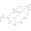
- FIG. 7 shows a schematic perspective view of a transparent member that can be used in the method according to another embodiment of the present invention.
- the transparent member 210 has a substantially triangular prism shape. That is, the transparent member 210 has an upper surface 221 and a lower surface 223 facing each other, and three side surfaces 225, 227, and 229.
- first surface 225 the side surface 225 to the side surface 229 are also referred to as "first surface 225", “second side surface 227”, and “inclined surface 229", respectively.
- the upper surface 221 and the lower surface 223 are right triangles congruent with each other. Therefore, the first surface 225 and the second side surface 227 are orthogonal to each other.
- the inclined surface 229 is inclined with respect to the first surface 225 at an inclination angle ⁇ , and is inclined with respect to the second side surface 227 at an inclination angle ⁇ .
- the X direction, the Y direction, and the Z direction are determined for the transparent member 210.
- the upper surface 221 and the lower surface 223 of the transparent member 210 are parallel to the XZ plane
- the first surface 225 is parallel to the XY plane
- the second side surface 227 is parallel to the YZ plane.
- FIG. 8 schematically shows a flow of a method of processing the transparent member 210 as shown in FIG. 7 (hereinafter referred to as “second method”).
- the second method is A step of irradiating a laser beam having a predetermined focal depth from a direction perpendicular to the first surface of the transparent member and scanning the laser beam in a direction parallel to the first surface.
- the focal depth is set to a height level in the range from the first surface to the lower end of the second side surface, and the laser beam is reflected by the inclined surface.
- the irradiation and scanning were performed at least twice at different focal depths.
- the first modified region is formed from the inclined surface to the second side surface in the scanning direction of the first laser beam.
- step S210 in which the second reforming region is formed, A step of processing a transparent member by applying an external force along a surface including a first modified region and a second modified region (step S220). Have.
- Step S210 First, the transparent member 210 as shown in FIG. 7 is irradiated with the laser beam, and the laser beam is scanned.
- FIG. 7 described above schematically shows an example of the scanning line L2 of the laser beam for the transparent member 210.
- FIG. 9 schematically shows a cross section of the transparent member 210 along the cut surface including the scanning line L2 shown in FIG. 7.
- the laser beam is emitted perpendicularly to the first surface 225 of the transparent member 210.
- the laser beam is scanned in the direction of arrow F from the left to the right (positive direction of the X-axis) in FIG.
- focus line 291 the trajectory of the focal point of this virtual laser beam that moves with the scanning of the laser beam.
- the focal line 291 is set in the range from the first surface 225 of the transparent member 210 to the lower end of the second side surface 227 in the irradiation direction of the laser beam (Z direction in FIG. 9).
- the first laser beam 201A which is described on the leftmost side in FIG. 9, is irradiated perpendicularly to the first surface 225 of the transparent member 210. , Reflected by the inclined surface 229, becomes the first reflected laser beam, and travels along the X direction.
- the focal point of the first laser beam 201A is set to the focal point 291A on the focal line 291
- the first reflected laser beam is from the intersection of the first laser beam 201A and the inclined surface 229 to the focal position 291A. Travel in the X direction by the distance corresponding to the distance of. As a result, the first reflected laser beam is focused at the point S1A inside the transparent member 210.
- a modified portion having a predetermined length including the point S1A is formed along the X direction.
- this modified portion is schematically represented by line 250A1.
- the second laser beam 201B irradiated on the right side of the first laser beam 201A by scanning has a distance from the first surface 225 to the focal point 291B shorter than the distance to the inclined surface 229. It does not reach the inclined surface 229. Therefore, the second laser beam 201B forms a modified portion 250B1 having a predetermined length including the focal point 291B inside the transparent member 210. Unlike the reforming section 250A1, the reforming section 250B1 extends in the Z direction.
- the modified portions 250C1 to 250H1 having a predetermined length are formed inside the transparent member 210 along the Z direction corresponding to the third laser beam 201C to the eighth laser beam 201H. ..
- the first modified region 255-1 along the X direction is formed inside the transparent member 210.
- FIG. 10 schematically shows a cross section of the transparent member 210 similar to that of FIG. However, in FIG. 10, the laser beam is adjusted so that the trajectory of the focal point due to scanning is not the focal line 291 but the focal line 292.
- the focal line 292 is set at a position farther than the focal line 291 from the first surface 225 in the irradiation direction of the laser beam (Z direction in FIG. 10).
- the focal line 292 is still set at a height between the first surface 225 and the lower end of the second side surface 227.
- the first laser beam 202A which is described on the leftmost side and is irradiated perpendicularly to the first surface 225 of the transparent member 210, is reflected by the inclined surface 229 of the transparent member 210 and is the first. It becomes the reflected laser light of, and travels along the X direction.
- the focal point of the first laser beam 202A is set to the point 292A on the focal line 292
- the first reflected laser beam is from the intersection of the first laser beam 202A and the inclined surface 229 to the focal point 292A. It travels in the X direction by the distance corresponding to the distance. As a result, the first reflected laser beam is focused at the point S2A inside the transparent member 210.
- a modified portion 250A2 having a predetermined length including the point S2A is formed along the X direction.
- the second laser beam 202B irradiated on the right side of the first laser beam 202A by scanning is reflected by the inclined surface 229 to become the second reflected laser beam, which travels along the X direction.
- the second reflected laser beam is from the intersection of the second laser beam 202B and the inclined surface 229 to the focal position 292B. Travel in the X direction by the distance corresponding to the distance of. As a result, the second reflected laser beam is focused at the point S2B inside the transparent member 210.
- a modified portion 250B2 having a predetermined length including the point S2B is formed along the X direction.
- the third laser beam 202C irradiated on the right side of the second laser beam 202B by scanning is inclined because the distance from the first surface 225 to the focal point 292C is shorter than the distance to the inclined surface 229. It does not reach surface 229.
- the third laser beam 202C forms a reforming portion 250C2 having a predetermined length including the focal point 292C inside the transparent member 210. Unlike the reforming portions 250A2 and B2, the reforming portion 250C2 extends in the Z direction.
- the modified portions 250D2 to 250H2 having a predetermined length are formed inside the transparent member 210 corresponding to the fourth laser beam 202D to the eighth laser beam 202H.
- a second modified region 255-2 along the X direction is formed inside the transparent member 210.
- the first modified region 255-1 and the second modified region 255-2 formed by the scanning so far may be integrated.
- the modified portion 250A2 extending in the X direction is formed in the above-mentioned first modified region 255-1. ..
- the focal depth of the laser beam is further changed, and the same process is repeated.
- FIG. 11 schematically shows a cross section of the transparent member 210 similar to that of FIGS. 9 and 10. However, in FIG. 11, the focal trajectory of the laser beam is set to the focal line 293, which is farther than the focal lines 291 and 292.
- the first laser beam 203A which is described on the leftmost side and is irradiated perpendicularly to the first surface 225 of the transparent member 210, is reflected by the inclined surface 229 of the transparent member 210 and is the first. It becomes a reflected laser beam and travels along the X direction.
- the focal point of the first laser beam 203A is set to the point 293A on the focal line 293
- the first reflected laser beam is from the intersection of the first laser beam 203A and the inclined surface 229 to the focal position 293A. Travel in the X direction by the distance corresponding to the distance of. As a result, the first reflected laser beam is focused at the point SnA of the transparent member 210.
- a modified portion 250An having a predetermined length including the point SnA is formed along the X direction.
- the second laser beam 203B irradiated on the right side of the first laser beam 203A by scanning is reflected by the inclined surface 229 to become the second reflected laser beam, which travels along the X direction.
- the focal point of the second laser beam 203B is set to the point 293B on the focal line 293
- the second reflected laser beam is from the intersection of the second laser beam 203B and the inclined surface 229 to the focal position 293B. Travel in the X direction by the distance corresponding to the distance of. As a result, the second reflected laser beam is focused at the point SnB inside the transparent member 210.
- a modified portion 250Bn having a predetermined length including the point SnB is formed along the X direction.
- modified portions 250Cn to 250Hn having a predetermined length extending in the X direction are formed inside the transparent member 210. ..
- an end face modification region 255-n is formed on the second side surface 227 of the transparent member 210 from the first surface 225 to the lower end of the second side surface 227 in the irradiation direction (Z direction) of the laser beam. be able to.
- an end face modification region may be formed in the vicinity of the surface of the inclined surface 229 of the transparent member 210, specifically, in a region from the surface of the inclined surface 229 to a depth of 2 mm.
- a plurality of modified regions along the X direction and the Z direction are formed inside the transparent member 210.
- the modified surface is formed so as to include the formed modified region.
- FIG. 12 schematically shows an example of the mode of the modified portion inside the transparent member 210 obtained after scanning the laser beam a plurality of times by changing the position of the focal line of the laser beam.
- a modified region along the X direction and the Z direction is formed inside the transparent member 210, and further, an XZ plane is formed.
- the modified surface 257 can be formed over the entire surface.
- Step S220 Next, the transparent member 210 is cut by applying an external force along the modified surface 257 formed by the steps up to the above.
- the method of cutting is not particularly limited, and the method described in the above-mentioned first method may be adopted.
- the transparent member 210 can be cut along a predetermined cut surface.
- a modified surface 257 having an end surface modified region 255-n is formed on the second side surface 227 of the transparent member 210.
- the transparent member 210 is cut along the modified surface 257, the possibility that the end face side such as the second side surface 227 is cut at an undesired position can be significantly suppressed.
- a characteristic split cross section in which the processing marks by laser processing extend in two directions can be obtained.
- FIG. 12 it is possible to form a split cross section in which processing marks by laser processing extend in a vertical and horizontal grid pattern.
- the end face modified region 255-n is formed. ..
- the order in which the end face modification regions 255-n are formed is not particularly limited.
- the end face modification region 255-n may be formed first, and then other modification regions (255-1, 255-2) may be formed. Alternatively, or in any other order, the end face modification regions 255-n may be formed.
- a substantially triangular columnar transparent member 210 having an inclined surface 229 is used, and the laser beam is reflected by using the inclined surface 229.
- a planar reflective member may be attached to the inclined surface 229 of the transparent member 210.
- the angle ⁇ between the inclined surface 229 and the first surface 225 is 45 °. Further, the angle ⁇ between the inclined surface 229 and the second side surface 227 is 45 °. However, angles other than 45 ° may be used as ⁇ and ⁇ .
- the transparent member was processed by adopting the method according to the embodiment of the present invention.
- the transparent member was a glass member, and the glass member was processed by using the second method described above.
- the glass member was a triangular prism, and the shapes of the upper and lower surfaces of the triangular prism were right-angled isosceles triangles.
- the inclined surface of the glass member is oriented at 45 ° with respect to the vertical direction, and the scanning surface of the laser beam (first surface 225) faces upward.
- a glass member was fixed on top.
- the scanning surface of the glass member arranged in this way was irradiated with the laser beam vertically from above.
- the scanning direction of the laser beam was set to be perpendicular to the stretching axis of the glass member, and the laser beam was scanned along the scanning line L2 shown in FIG. 7.
- an ultrashort pulse laser light having a wavelength of 1064 nm was used as the laser light.
- the pulse width of the laser beam is 10 picoseconds
- the pulse frequency of the burst is 75 kHz
- the output is 90% of the rating (50 W).
- the distance between the centers of the spots on the scanning line L2 was set to 5 ⁇ m.
- the height of the lower end of the second side surface of the glass member was defined as the focal depth of the laser beam, and the first laser beam scanning was performed (first run).
- the focal depth of the laser beam was made 0.5 mm shallower than that of the first run, and the second laser beam scanning was performed (second run). After that, the focal depth was reduced by 0.5 mm pitch, and the same scanning of the laser beam was repeated.
- laser light scanning was performed with the focal depth of the laser light on the first surface of the glass member.
- a CO 2 laser having a wavelength of 10.6 ⁇ m was used for the splitting process.
- the CO 2 laser scanned along the scanning line L2 described above.
- the scanning speed was 40 mm / s.
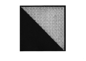
- FIG. 13 shows an example of a split cross section of a glass member.
- the split cross section was in a smooth state over the entire surface, and no unevenness or step was observed even at the end portion.
- the transparent member can be accurately cut at a desired position by using the method according to the embodiment of the present invention.
Landscapes
- Physics & Mathematics (AREA)
- Optics & Photonics (AREA)
- Engineering & Computer Science (AREA)
- Mechanical Engineering (AREA)
- Plasma & Fusion (AREA)
- Chemical & Material Sciences (AREA)
- Chemical Kinetics & Catalysis (AREA)
- General Chemical & Material Sciences (AREA)
- Oil, Petroleum & Natural Gas (AREA)
- Thermal Sciences (AREA)
- Materials Engineering (AREA)
- Organic Chemistry (AREA)
- Laser Beam Processing (AREA)
Abstract
透明部材を加工する方法であって、前記透明部材は、レーザ光の照射方向に対して垂直に延在する第1の表面と、前記第1の表面に接続された第2の表面および第3の表面とを有し、前記第1の表面に対して垂直な方向からレーザ光を照射し、前記レーザ光を前記第1の表面と平行な方向に沿って走査する工程であって、前記透明部材の前記第2の表面は、傾斜面であり、または前記透明部材の前記第2の表面の側には、傾斜面が配置され、前記傾斜面で前記レーザ光を、前記透明部材の前記第3の表面の方向に反射させることにより、前記透明部材の前記第3の表面において、前記第3の表面から深さ2mmまでの領域に、前記レーザ光の照射方向において、前記第1の表面から前記第3の表面の下端にわたって改質領域を形成する工程を有する方法。
Description
本発明は、透明部材を加工する方法に関する。
超短パルスレーザ光を用いて、ガラス基板を切断・分離し、切断片を形成する方法が知られている(例えば特許文献1)。
透明部材に超短パルスレーザ光を照射した場合、透明部材の内部に、レーザ光の照射方向に沿って改質部が形成される。従って、レーザ光を走査することにより、複数の改質部を含む改質面を形成することができる。また、この改質面に沿って、透明部材を切断することにより、切断片を分離することができる。
従来の方法を用いて、透明部材から物品を形成(割断)した際に、しばしば、物品が目標とする位置で割断されないという問題が生じ得る。特に、物品の端面では、割断位置が目標位置からずれる傾向が高くなり、この場合、所望の形状の物品が得られなくなる可能性が生じる。
本発明は、このような背景に鑑みなされたものであり、本発明では、より高い精度で、透明部材を加工する方法を提供することを目的とする。
本発明では、透明部材を加工する方法であって、
前記透明部材は、レーザ光の照射方向に対して垂直に延在する第1の表面と、前記第1の表面に接続された第2の表面および第3の表面とを有し、
前記第1の表面に対して垂直な方向からレーザ光を照射し、前記レーザ光を前記第1の表面と平行な方向に沿って走査する工程であって、
前記透明部材の前記第2の表面は、傾斜面であり、または前記透明部材の前記第2の表面の側には、傾斜面が配置され、
前記傾斜面で前記レーザ光を、前記透明部材の前記第3の表面の方向に反射させることにより、
前記透明部材の前記第3の表面において、前記第3の表面から深さ2mmまでの領域に、前記レーザ光の照射方向において、前記第1の表面から前記第3の表面の下端にわたって改質領域を形成する工程
を有する方法が提供される。
前記透明部材は、レーザ光の照射方向に対して垂直に延在する第1の表面と、前記第1の表面に接続された第2の表面および第3の表面とを有し、
前記第1の表面に対して垂直な方向からレーザ光を照射し、前記レーザ光を前記第1の表面と平行な方向に沿って走査する工程であって、
前記透明部材の前記第2の表面は、傾斜面であり、または前記透明部材の前記第2の表面の側には、傾斜面が配置され、
前記傾斜面で前記レーザ光を、前記透明部材の前記第3の表面の方向に反射させることにより、
前記透明部材の前記第3の表面において、前記第3の表面から深さ2mmまでの領域に、前記レーザ光の照射方向において、前記第1の表面から前記第3の表面の下端にわたって改質領域を形成する工程
を有する方法が提供される。
また、本発明では、透明部材を加工する方法であって、
前記透明部材は、レーザ光の照射方向に対して垂直に延在する第1の表面と、前記第1の表面に接続された第1の側面および第2の側面とを有し、前記透明部材の前記第1の側面の側には、前記第1の側面に対面または接触するように反射部材が設けられ、
(1)前記第1の表面に対して垂直な方向から、所定の焦点深さを有するレーザ光を照射し、前記レーザ光を前記第1の表面と平行な方向に走査し、
前記焦点深さは、前記レーザ光の照射方向において、前記第1の表面から、前記第2の側面の下端よりも遠い位置に設定され、前記レーザ光は、前記反射部材で反射され、前記第1の側面に入射され、
前記照射および走査は、前記焦点深さを変えて、少なくとも2回実施され、
第1のレーザ光の照射および走査では、前記レーザ光の照射方向において、前記第1の表面から前記第2の側面の下端にわたって、第1の改質領域が形成され、第2のレーザ光の照射および走査では、前記レーザ光の照射方向において、前記第1の表面から前記第2の側面の下端にわたって、第2の改質領域が形成され、
前記第1または第2の改質領域は、前記第2の側面の表面から深さ2mmまでの領域に形成され、
(2)前記第1の改質領域および前記第2の改質領域を含む面に沿って外力を加えることにより、前記透明部材を加工する、方法が提供される。
前記透明部材は、レーザ光の照射方向に対して垂直に延在する第1の表面と、前記第1の表面に接続された第1の側面および第2の側面とを有し、前記透明部材の前記第1の側面の側には、前記第1の側面に対面または接触するように反射部材が設けられ、
(1)前記第1の表面に対して垂直な方向から、所定の焦点深さを有するレーザ光を照射し、前記レーザ光を前記第1の表面と平行な方向に走査し、
前記焦点深さは、前記レーザ光の照射方向において、前記第1の表面から、前記第2の側面の下端よりも遠い位置に設定され、前記レーザ光は、前記反射部材で反射され、前記第1の側面に入射され、
前記照射および走査は、前記焦点深さを変えて、少なくとも2回実施され、
第1のレーザ光の照射および走査では、前記レーザ光の照射方向において、前記第1の表面から前記第2の側面の下端にわたって、第1の改質領域が形成され、第2のレーザ光の照射および走査では、前記レーザ光の照射方向において、前記第1の表面から前記第2の側面の下端にわたって、第2の改質領域が形成され、
前記第1または第2の改質領域は、前記第2の側面の表面から深さ2mmまでの領域に形成され、
(2)前記第1の改質領域および前記第2の改質領域を含む面に沿って外力を加えることにより、前記透明部材を加工する、方法が提供される。
さらに、本発明では、透明部材を加工する方法であって、
前記透明部材は、レーザ光の照射方向に対して垂直に延在する第1の表面と、前記第1の表面に接続された第2の表面および第3の表面を有し、前記第2の表面は、傾斜面であり、
(1)前記第1の表面に対して垂直な方向から、所定の焦点深さを有するレーザ光を照射し、前記レーザ光を前記第1の表面と平行な方向に走査し、
前記焦点深さは、前記レーザ光の照射方向において、前記第1の表面から前記第3の表面の下端の間の深さ位置に設定され、前記レーザ光は、前記第2の表面で反射され、
前記照射および走査は、前記焦点深さを変えて、少なくとも2回実施され、
第1のレーザ光の照射および走査では、前記第1のレーザ光の走査方向において、前記第2の表面から前記第3の表面にわたって、第1の改質領域が形成され、
第2のレーザ光の照射および走査では、前記第3の表面から深さ2mmまでの領域に、前記第2のレーザ光の照射方向において、前記第1の表面から前記第3の表面の下端にわたって、第2の改質領域が形成され、
(2)前記第1の改質領域および前記第2の改質領域を含む面に沿って外力を加えることにより、前記透明部材を加工する、方法が提供される。
前記透明部材は、レーザ光の照射方向に対して垂直に延在する第1の表面と、前記第1の表面に接続された第2の表面および第3の表面を有し、前記第2の表面は、傾斜面であり、
(1)前記第1の表面に対して垂直な方向から、所定の焦点深さを有するレーザ光を照射し、前記レーザ光を前記第1の表面と平行な方向に走査し、
前記焦点深さは、前記レーザ光の照射方向において、前記第1の表面から前記第3の表面の下端の間の深さ位置に設定され、前記レーザ光は、前記第2の表面で反射され、
前記照射および走査は、前記焦点深さを変えて、少なくとも2回実施され、
第1のレーザ光の照射および走査では、前記第1のレーザ光の走査方向において、前記第2の表面から前記第3の表面にわたって、第1の改質領域が形成され、
第2のレーザ光の照射および走査では、前記第3の表面から深さ2mmまでの領域に、前記第2のレーザ光の照射方向において、前記第1の表面から前記第3の表面の下端にわたって、第2の改質領域が形成され、
(2)前記第1の改質領域および前記第2の改質領域を含む面に沿って外力を加えることにより、前記透明部材を加工する、方法が提供される。
本発明では、より高い精度で、透明部材を加工する方法を提供することができる。
以下、図面を参照して、本発明の一実施形態について説明する。
前述のように、従来の方法では、透明部材から物品を割断した際に、しばしば、物品が目標とする位置で割断されないという問題が生じ得る。特に、物品の端面では、割断位置が目標位置からずれる傾向が高くなり、この場合、所望の形状の物品が得られなくなる可能性が生じる。
図1を用いて、このような問題の要因について検討する。
図1には、従来の方法により、透明部材を割断する際の一工程を模式的に示す。
図1に示すように、この方法では、超短パルスレーザ光1を用いて、透明部材10が加工される。透明部材10は、上面12、下面14および側面16を有する。割断の際には、透明部材10の上面12の側から、レーザ光1が垂直に照射される。また、レーザ光1は、上面12にわたって矢印Fの方向に走査される。
ここで、レーザ光1が図1の左の位置にある場合、レーザ光1の光束1Aは、透明部材10の下面14の点C1で焦点化される。従って、透明部材10には、点C1を通るように、上面12から下面14にわたって、改質部50が形成される。
なお、図1では、改質部50は、線状に記載されている。ただし、実際には、改質部50は、走査方向Fの方向に、ある程度の幅を有する領域として形成される。従って、レーザ光1を矢印Fの方向に走査させることにより、複数の改質部50を含む改質面が形成される。
ただし、レーザ光1が図1の右の位置にある場合、レーザ光1の光束1Bは、透明部材10の下面14で焦点化することができなくなる。この位置では、レーザ光1の光束1Bの右端側が、上面12ではなく、側面16に入射される結果、光束1Bの右端が、光束1Bの左端の集束点C2とは異なる点C3に集束されるためである。
このような現象のため、透明部材10の側面16では、上面12から下面14にわたって、適正な改質部を形成することは難しくなる。透明部材10の側面16とは反対の側面(図示されていない)においても、同様の現象が生じる。
その結果、レーザ光1の照射後には、側面16の側に適正な改質部を有しない透明部材10が得られる。従って、その後、そのような透明部材10を改質面に沿って割断した場合、端面(側面16)では、所望の位置に沿った分離を行うことができなくなってしまう。
以上のことから、従来の方法では、所望の形状の物品を得ることが難しい場合がある。特に、透明部材が厚い場合、このような問題は、より顕著になる。
これに対して、本発明の一実施形態では、透明部材を加工する方法であって、
前記透明部材は、レーザ光の照射方向に対して垂直に延在する第1の表面と、前記第1の表面に接続された第2の表面および第3の表面とを有し、
前記第1の表面に対して垂直な方向からレーザ光を照射し、前記レーザ光を前記第1の表面と平行な方向に沿って走査する工程であって、
前記透明部材の前記第2の表面は、傾斜面であり、または前記透明部材の前記第2の表面の側には、傾斜面が配置され、
前記傾斜面で前記レーザ光を、前記透明部材の前記第3の表面の方向に反射させることにより、
前記透明部材の前記第3の表面において、前記第3の表面から深さ2mmまでの領域に、前記レーザ光の照射方向において、前記第1の表面から前記第3の表面の下端にわたって改質領域を形成する工程
を有する方法が提供される。
前記透明部材は、レーザ光の照射方向に対して垂直に延在する第1の表面と、前記第1の表面に接続された第2の表面および第3の表面とを有し、
前記第1の表面に対して垂直な方向からレーザ光を照射し、前記レーザ光を前記第1の表面と平行な方向に沿って走査する工程であって、
前記透明部材の前記第2の表面は、傾斜面であり、または前記透明部材の前記第2の表面の側には、傾斜面が配置され、
前記傾斜面で前記レーザ光を、前記透明部材の前記第3の表面の方向に反射させることにより、
前記透明部材の前記第3の表面において、前記第3の表面から深さ2mmまでの領域に、前記レーザ光の照射方向において、前記第1の表面から前記第3の表面の下端にわたって改質領域を形成する工程
を有する方法が提供される。
本発明の一実施形態では、透明部材の第2の表面の側に、傾斜面が配置される。この傾斜面は、透明部材とは別の部材により提供されてもよい。あるいは、傾斜面は、透明部材の第2の表面そのものであってもよい。
また、本発明の一実施形態では、前記透明部材に、第1の表面に対して垂直な方向から入射されるレーザ光は、傾斜面によって反射される。この反射されたレーザ光は、透明部材の内部を、第3の表面に向かって進行する。
従って、レーザ光の焦点深さを調整することにより、レーザ光を第1の表面に平行な方向に沿って走査した際に、透明部材の第3の表面の近傍に、レーザ光の照射方向において、第1の表面から第3の表面の下端にわたって延伸する改質領域を形成することができる。
具体的には、第3の表面から深さ2mmまでの領域に、第1の表面から第3の表面の下端にわたって延伸する改質領域を形成することができる。
具体的には、第3の表面から深さ2mmまでの領域に、第1の表面から第3の表面の下端にわたって延伸する改質領域を形成することができる。
ここで、「対象の表面から深さ2mmまでの領域に改質領域を形成する」とは、改質領域の対象の表面に近い方の先端が、前記対象の表面から深さ2mmまでの領域内に存在することを意味する。従って、「表面から深さ2mmまでの領域に改質領域を形成する」という表現は、必ずしも、対象の表面から深さ2mmまでの領域全体に、改質領域が形成されることを意味しない。なお、通常、改質領域の対象の表面から遠い側の先端は、別のレーザ光の照射により生じた改質領域との重なりの結果、しばしば、正確に判別できないことが生じ得る。
本願では、以降、改質領域の対象の表面に近い方の先端が、前記対象の表面から深さ2mmまでの領域内に存在する改質領域を、特に「端面改質領域」とも称する。
改質領域の対象の表面に近い方の先端は、対象の表面上にある(すなわち深さ0の位置にある)ことが好ましい。
また、第3の表面の「下端」とは、第3の表面の端部のうち、第1の表面とは反対側にある端部を意味する。例えば、図1に示す透明部材10の場合、側面16の「下端」は、側面16が下面14と接触する位置に相当する。
また、本願において、レーザ光の照射方向に関して使用される「垂直」と言う用語は、レーザ光の照射方向と被照射面とのなす角度が厳密に90゜である場合の他、なす角度が75°~105°の範囲を含むものとする。なす角度は、好ましくは80°~100°であり、より好ましくは85°~95°であり、最も好ましくは90°である。
本発明の一実施形態では、レーザ光の焦点深さを変えて、前述のようなレーザ光の照射および走査を繰り返すことにより、透明部材の内部に、端面改質領域を含む改質面を形成することができる。従って、その後、改質面に沿って、透明部材に外力を加えることにより、透明部材を割断することができる。
本発明の一実施形態による方法では、透明部材の第3の表面の端部には、端面改質領域が形成される。このため、透明部材を改質面に沿って割断した際に、端面側が目的としない位置で分断される可能性を有意に抑制することができる。従って、本発明の一実施形態による方法では、より高い精度で透明部材を割断することが可能となる。
特に、本発明の一実施形態による方法では、透明部材が厚い場合であっても、高い精度で透明部材を割断することが可能となる。
なお、本願において、「改質領域」とは、レーザ光によって改質された透明部材の領域を意味する。「改質領域」には、通常、ボイドおよび/または微細亀裂が形成される。また、「改質部」とは、レーザ光の進行方向に沿って形成された、透明部材の表面および内部における略線状の改質部分を意味する。「改質部」にも、通常、ボイドおよび/または微細亀裂が形成される。
「改質領域」と「改質部」の主な違いは、「改質部」がレーザ光の透明部材内の進行方向に沿って延伸する方向性を有するのに対して、「改質領域」は、必ずしもそのような方向性を有しないことである。すなわち、「改質部」は、レーザ光の透明部材内の進行方向に沿って延在する。一方、「改質領域」は、レーザ光の透明部材内の進行方向とは異なる方向に沿って延在し、例えばレーザ光の透明部材内の進行方向に対して垂直な方向(例えば、レーザ光の走査方向)に延在する。通常の場合、複数の「改質部」が所定の方向に配列されることにより、前記所定の方向に延在する「改質領域」が形成される。
なお、レーザ光の進行方向は、透明部材の内部に生じるレーザ痕を観察することにより判断できる。
また、本発明の一実施形態では、透明部材を加工する方法であって、
前記透明部材は、レーザ光の照射方向に対して垂直に延在する第1の表面と、前記第1の表面に接続された第1の側面および第2の側面とを有し、前記透明部材の前記第1の側面の側には、前記第1の側面に対面または接触するように反射部材が設けられ、
(1)前記第1の表面に対して垂直な方向から、所定の焦点深さを有するレーザ光を照射し、前記レーザ光を前記第1の表面と平行な方向に走査し、
前記焦点深さは、前記レーザ光の照射方向において、前記第1の表面から、前記第2の側面の下端よりも遠い位置に設定され、前記レーザ光は、前記反射部材で反射され、前記第1の側面に入射され、
前記照射および走査は、前記焦点深さを変えて、少なくとも2回実施され、
第1のレーザ光の照射および走査では、前記レーザ光の照射方向において、前記第1の表面から前記第2の側面の下端にわたって、第1の改質領域が形成され、第2のレーザ光の照射および走査では、前記レーザ光の照射方向において、前記第1の表面から前記第2の側面の下端にわたって、第2の改質領域が形成され、
前記第1または第2の改質領域は、前記第2の側面の表面から深さ2mmまでの領域に形成され、
(2)前記第1の改質領域および前記第2の改質領域を含む面に沿って外力を加えることにより、前記透明部材を加工する、方法が提供される。
前記透明部材は、レーザ光の照射方向に対して垂直に延在する第1の表面と、前記第1の表面に接続された第1の側面および第2の側面とを有し、前記透明部材の前記第1の側面の側には、前記第1の側面に対面または接触するように反射部材が設けられ、
(1)前記第1の表面に対して垂直な方向から、所定の焦点深さを有するレーザ光を照射し、前記レーザ光を前記第1の表面と平行な方向に走査し、
前記焦点深さは、前記レーザ光の照射方向において、前記第1の表面から、前記第2の側面の下端よりも遠い位置に設定され、前記レーザ光は、前記反射部材で反射され、前記第1の側面に入射され、
前記照射および走査は、前記焦点深さを変えて、少なくとも2回実施され、
第1のレーザ光の照射および走査では、前記レーザ光の照射方向において、前記第1の表面から前記第2の側面の下端にわたって、第1の改質領域が形成され、第2のレーザ光の照射および走査では、前記レーザ光の照射方向において、前記第1の表面から前記第2の側面の下端にわたって、第2の改質領域が形成され、
前記第1または第2の改質領域は、前記第2の側面の表面から深さ2mmまでの領域に形成され、
(2)前記第1の改質領域および前記第2の改質領域を含む面に沿って外力を加えることにより、前記透明部材を加工する、方法が提供される。
このような実施形態は、例えば、直方体形状の透明部材を割断する際に有意である。
なお、本願において、レーザ光の照射方向に関して使用される「平行」と言う用語は、レーザ光の照射方向と被照射面とが厳密に平行である場合の他、両者のなす角度が±15゜以内の範囲を含むものとする。両者のなす角度は、好ましくは±10゜以内であり、より好ましくは±5゜以内であり、最も好ましくは0°である。
また、本発明の一実施形態では、透明部材を加工する方法であって、
前記透明部材は、レーザ光の照射方向に対して垂直に延在する第1の表面と、前記第1の表面に接続された第2の表面および第3の表面を有し、前記第2の表面は、傾斜面であり、
(1)前記第1の表面に対して垂直な方向から、所定の焦点深さを有するレーザ光を照射し、前記レーザ光を前記第1の表面と平行な方向に走査し、
前記焦点深さは、前記レーザ光の照射方向において、前記第1の表面から前記第3の表面の下端の間の深さ位置に設定され、前記レーザ光は、前記第2の表面で反射され、
前記照射および走査は、前記焦点深さを変えて、少なくとも2回実施され、
第1のレーザ光の照射および走査では、前記第1のレーザ光の走査方向において、前記第2の表面から前記第3の表面にわたって、第1の改質領域が形成され、
第2のレーザ光の照射および走査では、前記第3の表面から深さ2mmまでの領域に、前記第2のレーザ光の照射方向において、前記第1の表面から前記第3の表面の下端にわたって、第2の改質領域が形成され、
(2)前記第1の改質領域および前記第2の改質領域を含む面に沿って外力を加えることにより、前記透明部材を加工する、方法が提供される。
前記透明部材は、レーザ光の照射方向に対して垂直に延在する第1の表面と、前記第1の表面に接続された第2の表面および第3の表面を有し、前記第2の表面は、傾斜面であり、
(1)前記第1の表面に対して垂直な方向から、所定の焦点深さを有するレーザ光を照射し、前記レーザ光を前記第1の表面と平行な方向に走査し、
前記焦点深さは、前記レーザ光の照射方向において、前記第1の表面から前記第3の表面の下端の間の深さ位置に設定され、前記レーザ光は、前記第2の表面で反射され、
前記照射および走査は、前記焦点深さを変えて、少なくとも2回実施され、
第1のレーザ光の照射および走査では、前記第1のレーザ光の走査方向において、前記第2の表面から前記第3の表面にわたって、第1の改質領域が形成され、
第2のレーザ光の照射および走査では、前記第3の表面から深さ2mmまでの領域に、前記第2のレーザ光の照射方向において、前記第1の表面から前記第3の表面の下端にわたって、第2の改質領域が形成され、
(2)前記第1の改質領域および前記第2の改質領域を含む面に沿って外力を加えることにより、前記透明部材を加工する、方法が提供される。
このような実施形態は、例えば、傾斜面を有する角柱状の透明部材を割断する際に有意である。
(本発明の一実施形態による方法が適用され得る透明部材)
本発明の一実施形態による方法に使用される透明部材は、透明である限り、特に限られない。例えば、透明部材は、レーザ光の少なくとも一部が線形吸収形態で伝達されるような吸収スペクトルおよび厚さを有する部材であればよい。透明部材は、例えば、ガラスで構成されてもよい。
本発明の一実施形態による方法に使用される透明部材は、透明である限り、特に限られない。例えば、透明部材は、レーザ光の少なくとも一部が線形吸収形態で伝達されるような吸収スペクトルおよび厚さを有する部材であればよい。透明部材は、例えば、ガラスで構成されてもよい。
また、透明部材は、いかなる形状を有してもよい。透明部材は、例えば、板状、ブロック状、または棒状であってもよい。
透明部材は、例えば、直方体形状または角柱形状(例えば三角柱または四角柱など)を有してもよい。
透明部材の厚さは、特に限られない。透明部材の厚さは、例えば、1mm以上であり、2mm以上であることが好ましく、5mm以上であることがより好ましい。透明部材の厚さは、例えば19mm以下であってもよい。前述のように、本発明の一実施形態では、「厚い」透明部材に対しても、適正な位置で割断を行うことができる。
なお、透明部材の「厚さ」とは、透明部材の最も短い寸法を意味する。例えば、透明部材が直方体の場合、厚さは、縦、横、および高さの寸法のうち、最も短い寸法を表す。また、透明部材が角柱の場合、通常、厚さは、延伸軸に垂直な断面における各辺の中の最小寸法である。
(レーザ光)
本発明の一実施形態による方法に使用されるレーザ光は、透明部材の内部に改質領域を形成することができる限り、特に限られない。
本発明の一実施形態による方法に使用されるレーザ光は、透明部材の内部に改質領域を形成することができる限り、特に限られない。
レーザ光は、例えば、パルス幅がフェムト秒オーダ~ナノ秒オーダ、すなわち1.0×10⁻¹⁵~9.9×10⁻⁹秒の短パルスレーザである。短パルスレーザは、バーストパルスであることが好ましい。短パルスレーザの平均出力は、例えば30W以上である。
バーストパルスのレーザ光のレーザ出力は、定格(50W)の90%程度、バーストの周波数は60kHz程度、バーストの時間幅は20ピコ秒~165ナノ秒が挙げられる。バーストの時間幅としては、好ましい範囲として、10ナノ秒~100ナノ秒が挙げられる。
なお、レーザ光の走査は、一つの焦点深さに対して1回だけ実施されても、複数回実施されてもよい。
本発明の一実施形態により透明部材を加工して得られる物品は、例えば光学部材である。
(本発明の一実施形態による透明部材を加工する方法)
以下、図2~図6を参照して、本発明の一実施形態による透明部材を加工する方法について、より詳しく説明する。
以下、図2~図6を参照して、本発明の一実施形態による透明部材を加工する方法について、より詳しく説明する。
図2には、本発明の一実施形態による方法に用いられ得る透明部材の模式的な斜視図を示す。
図2に示すように、この透明部材110は、実質的に直方体形状を有する。すなわち、透明部材110は、相互に対向する第1の表面112および第2の表面114と、4つの側面115、116、117および118とを有する。側面115と側面117は、相互に対向しており、側面116と側面118も、相互に対向している。なお、側面116および側面118を、それぞれ、特に、「第1の側面116」および「第2の側面118」とも称する。
透明部材110に対して、図2に示すように、X方向、Y方向およびZ方向を定める。この規定によれば、透明部材110の第1の表面112および第2の表面114は、XY平面に平行であり、第1の側面116および第2の側面118は、YZ平面に平行である。
また、図2には、透明部材110に接触するようにして配置された、反射部材130も示されている。
反射部材130は、略三角柱状の形状を有し、上面131および底面132と、前記上面131および底面132の間に延在する3つの面とを有する。3つの面は、それぞれ、第1の面133、第2の面135、および傾斜面137と称される。このうち、第1の面133と第2の面135は、直交している。一方、傾斜面137は、第1の面133に対して傾斜角αで傾斜し、第2の面135に対して傾斜角βで傾斜するように配置される。
図2の例では、傾斜角α=β=45゜である。
反射部材130の傾斜面137は、レーザ光を反射する機能を有する。
反射部材130の第2の面135は、透明部材110の第1の側面116と同一の形状を有する。
反射部材130は、透明部材110の第1の側面116の側に設けられる。具体的には、反射部材130は、前記反射部材130の第2の面135の全ての辺が、透明部材110の第1の側面116の全ての辺と一致するようにして、透明部材110に対して密着して配置される。また、反射部材130は、前記反射部材130の第1の面133が、透明部材110の第1の表面112と同一平面となるようにして、透明部材110に対して配置される。
ただし、図2に示した反射部材130の寸法および透明部材110に対する配置は、単なる一例である。例えば、反射部材130は、第2の面135が透明部材110の第1の側面と非接触な状態で配置されてもよい。また、反射部材130の第1の面133は、透明部材110の第1の表面112よりも突出しており、反射部材130と透明部材110との境界は、段差になっていてもよい。
図3には、図2に示したような透明部材110を加工する方法(以下、「第1の方法」と称する)のフローを概略的に示す。
図3に示すように、第1の方法は、
(1)透明部材の第1の表面に対して垂直な方向から、所定の焦点深さを有するレーザ光を照射し、前記レーザ光を第1の表面と平行な方向に走査する工程であって、
焦点深さは、第1の表面から、第2の側面の下端よりも遠い位置に設定され、レーザ光は、反射部材の傾斜面で反射され、透明部材の第1の側面に入射され、
前記照射および走査は、焦点深さを変えて、少なくとも2回実施され、
第1のレーザ光の照射および走査では、第1のレーザ光の照射方向において、第1の表面から第2の側面の下端にわたって、第1の改質領域が形成され、
第2のレーザ光の照射および走査では、第2のレーザ光の照射方向において、第1の表面から第2の側面の下端にわたって、第2の改質領域が形成され、
第1または第2の改質領域は、第2の側面の表面から深さ2mmまでの領域に形成される、工程(S110)と、
(2)第1の改質領域および第2の改質領域を含む面に沿って外力を加えることにより、透明部材を加工する工程(S120)と、
を有する。
(1)透明部材の第1の表面に対して垂直な方向から、所定の焦点深さを有するレーザ光を照射し、前記レーザ光を第1の表面と平行な方向に走査する工程であって、
焦点深さは、第1の表面から、第2の側面の下端よりも遠い位置に設定され、レーザ光は、反射部材の傾斜面で反射され、透明部材の第1の側面に入射され、
前記照射および走査は、焦点深さを変えて、少なくとも2回実施され、
第1のレーザ光の照射および走査では、第1のレーザ光の照射方向において、第1の表面から第2の側面の下端にわたって、第1の改質領域が形成され、
第2のレーザ光の照射および走査では、第2のレーザ光の照射方向において、第1の表面から第2の側面の下端にわたって、第2の改質領域が形成され、
第1または第2の改質領域は、第2の側面の表面から深さ2mmまでの領域に形成される、工程(S110)と、
(2)第1の改質領域および第2の改質領域を含む面に沿って外力を加えることにより、透明部材を加工する工程(S120)と、
を有する。
以下、図4~図6を参照して、各工程について説明する。
(工程S110)
まず、前述の図2に示したような、透明部材110および反射部材130(以下、これらをまとめて、「組立体」140と称する)に、レーザ光が照射される。また、レーザ光が組立体140の上面に沿って走査される。
まず、前述の図2に示したような、透明部材110および反射部材130(以下、これらをまとめて、「組立体」140と称する)に、レーザ光が照射される。また、レーザ光が組立体140の上面に沿って走査される。
図2には、組立体140に対するレーザ光の走査線L1の一例が模式的に示されている。なお、図2に示した例では、レーザ光の走査線L1は、反射部材130の第1の面133上に留まっており、レーザ光は、透明部材110の第1の表面112上には走査されていない。
しかしながら、走査線L1をさらに延伸させて、レーザ光を、透明部材110の第1の表面112も含むように走査してもよい。
図4には、図2に示した走査線L1を含む切断面に沿った、組立体140の断面を模式的に示す。
図4に示すように、レーザ光は、反射部材130の第1の面133(すなわち透明部材110の第1の表面112)に対して垂直に照射される。
レーザ光は、図4の左から右(X軸の正方向)に沿って、矢印Fの方向に走査される。ただし、前述のように、この例では、レーザ光は、透明部材110の第1の表面112上には走査されない。
ここで、組立体140が存在しない場合、レーザ光の走査に伴い、レーザ光の焦点は、X軸の正方向に沿って移動する。以下、レーザ光の走査に伴って移動する、この仮想的なレーザ光の焦点の軌跡を、「焦点線191」と称する。
焦点線191は、レーザ光の照射方向(図4のZ方向)において、透明部材110の第2の側面118の下端、すなわち第2の表面114よりも遠い位置に設定される。
ここで、レーザ光が矢印Fの方向に走査されると、最も左側に記載された、組立体140に対して垂直に照射される第1のレーザ光101Aは、反射部材130の傾斜面137で反射され、第1の反射レーザ光101RAとなり、X方向に沿って進行する。
第1のレーザ光101Aの焦点は、焦点線191上の点191Aに設定されているため、第1の反射レーザ光101RAは、第1のレーザ光101Aと傾斜面137との交点から焦点位置191Aまでの距離に対応する距離だけ、X方向に進行する。その結果、第1の反射レーザ光101RAは、反射部材130の第2の面135と接する透明部材110の第1の側面116から、透明部材110の内部に進行し、内部の点R1Aで焦点化される。
これにより、X方向に沿って、点R1Aを含む所定の長さの改質部が形成される。図4では、この改質部は、概略的に線150A1(改質部150A1)で表されている。
次に、走査によって、第1のレーザ光101Aよりも右側で照射される第2のレーザ光101Bは、傾斜面137で反射され、第2の反射レーザ光101RBとなり、X方向に沿って進行する。
第2のレーザ光101Bの焦点は、焦点線191上の点191Bに設定されているため、第2の反射レーザ光101RBは、第2のレーザ光101Bと傾斜面137との交点から焦点位置191Bまでの距離に対応する距離だけ、X方向に進行する。その結果、第2の反射レーザ光101RBは、透明部材110の内部に進行し、内部の点R1Bで焦点化される。
これに伴い、X方向に沿って、点R1Bを含む所定の長さの改質部150B1が形成される。
以下同様に、第3のレーザ光101C~第8のレーザ光101Hに対応して、透明部材110の内部に、所定の長さの改質部150C1~150H1が形成される。
その結果、透明部材110の内部に、レーザ光の照射方向(Z方向)、すなわち第1の表面112から第2の表面114に沿って、第1の改質領域155-1が形成される。
第1の改質領域155-1の延在方向は、Z方向であり、これは、第1の改質領域155-1に含まれる各改質部150A1~150H1の延在方向(X方向)とは垂直であることに留意する必要がある。
次に、レーザ光の焦点深さを変えて、前述の工程S110が繰り返される。
図5には、図4と同様の組立体140の断面が模式的に示されている。ただし、図5では、レーザ光は、組立体140が存在しない場合の走査による焦点の軌跡が、焦点線191ではなく、焦点線192となるように調整される。焦点線192は、レーザ光の照射方向(図5のZ方向)において、反射部材130の第1の面133、すなわち透明部材110の第1の表面112から、焦点線191よりも遠い位置に設定される。
本工程においても、最も左側に記載された、反射部材130の第1の面133に対して垂直に照射される第1のレーザ光102Aは、反射部材130の傾斜面137で反射され、第1の反射レーザ光102RAとなり、X方向に沿って進行する。
第1のレーザ光102Aの焦点は、焦点線192上の点192Aに設定されているため、第1の反射レーザ光102RAは、第1のレーザ光102Aと傾斜面137との交点から焦点192Aまでの距離に対応する距離だけ、X方向に進行する。その結果、第1の反射レーザ光102RAは、反射部材130の第2の面135と接する透明部材110の第1の側面116から、透明部材110の内部に進行し、点R2Aで焦点化される。
これに伴い、点R2Aを起点として、X方向に沿って、所定の長さの改質部150A2が形成される。
次に、走査によって、第1のレーザ光102Aよりも右側で照射される第2のレーザ光102Bは、傾斜面137で反射され、第2の反射レーザ光102RBとなり、X方向に沿って進行する。
第2のレーザ光102Bの焦点は、焦点線192上の点192Bに設定されているため、第2の反射レーザ光102RBは、第2のレーザ光102Bと傾斜面137との交点から焦点位置192Bまでの距離に対応する距離だけ、X方向に進行する。その結果、第2の反射レーザ光102RBは、透明部材110の内部に進行し、点R2Bで焦点化される。
これに伴い、X方向に沿って、点R2Bを含む所定の長さの改質部150B2が形成される。
以下同様に、第3のレーザ光102C~第8のレーザ光102Hに対応して、透明部材110の内部に、所定の長さの改質部150C2~150H2が形成される。
その結果、透明部材110の内部に、Z方向に沿った第2の改質領域155-2が形成される。前述の走査で形成された第1の改質領域155-1と、第2の改質領域155-2とは、一体化されてもよい。
必要な場合、さらに、レーザ光の焦点深さを変えて、同様の工程が繰り返される。
図6には、図4および図5と同様の、組立体140の断面が模式的に示されている。ただし、図6では、レーザ光の焦点の軌跡が、透明部材110の第1の表面112から焦点線191および192よりも遠い、焦点線193に設定されている。
この場合も、最も左側に記載された、反射部材130の第1の面133に対して垂直に照射される第1のレーザ光103Aは、反射部材130の傾斜面137で反射され、第1の反射レーザ光103RAとなり、X方向に沿って進行する。
第1のレーザ光103Aの焦点は、焦点線193上の点193Aに設定されているため、第1の反射レーザ光103RAは、第1のレーザ光103Aと傾斜面137との交点から焦点位置193Aまでの距離に対応する距離だけ、X方向に進行する。その結果、第1の反射レーザ光103RAは、透明部材110の点RnAで焦点化される。
これに伴い、X方向に沿って、点RnAを含む所定の長さの改質部150Anが形成される。
次に、走査によって、第1のレーザ光103Aよりも右側で照射される第2のレーザ光103Bは、傾斜面137で反射され、第2の反射レーザ光103RBとなり、X方向に沿って進行する。
第2のレーザ光103Bの焦点は、焦点線193上の点193Bに設定されているため、第2の反射レーザ光103RBは、第2のレーザ光103Bと傾斜面137との交点から焦点位置193Bまでの距離に対応する距離だけ、X方向に進行する。その結果、第2の反射レーザ光103RBは、透明部材110の内部に進行し、点RnBで焦点化される。
これに伴い、X方向に沿って、点RnBを含む所定の長さの改質部150Bnが形成される。
以下同様に、第3のレーザ光103C~第8のレーザ光103Hに対応して、透明部材110の内部に、所定の長さの改質部150Cn~150Hnが形成される。
その結果、透明部材110の内部に、Z方向に沿った第nの改質領域155-nが形成される。また、それまでの工程で形成された改質領域全てを含む、改質面157が形成される。
工程S110では、このように、焦点線の位置を変えて走査を行うことにより、透明部材110の第2の側面118に、「端面改質領域」155-nが形成される。
なお、第1の方法では、必要な場合、透明部材110の第1の側面116にも「端面改質領域」が形成されるように、レーザ光の焦点線を調整してもよい(図4参照)。
透明部材110の第1の側面116の近傍と第2の側面118の近傍の両方に、Z方向に沿って「端面改質領域」を形成した場合、次の工程S120において、よりいっそう高い精度で、透明部材110を割断することが可能となる。
(工程S120)
次に、前述までの工程により形成された改質面157に沿って、外力を加えることにより、透明部材110が割断される。
次に、前述までの工程により形成された改質面157に沿って、外力を加えることにより、透明部材110が割断される。
割断の方法は、特に限られない。
透明部材110の割断は、例えば、透明部材110を局部的に加熱する方法、または局部的に冷却する方法などにより、実施されてもよい。
例えば、割断用レーザを用いて、透明部材110の第1の表面112にレーザ光を照射し、透明部材110の改質面157に沿ってレーザ光を走査することにより、透明部材110を割断してもよい。あるいは、割断用レーザは、透明部材110の第2の表面114の側から照射されてもよい。
そのような割断用レーザは、CO2レーザであってもよい。
以上の工程により、透明部材110を割断することができる。
第1の方法では、透明部材110の第2の側面118に形成された端面改質領域155-nを有する改質面157が形成される。
従って、透明部材110を改質面157に沿って割断した際に、第2の側面118のような端面側が、目的としない位置で分断される可能性を有意に抑制することができる。
第1の方法では、反射レーザ光の進行方向(図4~図6におけるX方向)に沿って延在する複数のレーザ加工痕を有する、特徴的な割断面が得られる。
なお、第1の方法では、前述の図2における走査線L1に示したように、レーザ光の走査は、反射部材130の領域に留まり、透明部材110の第1の表面112に、レーザ光は走査されない。
しかしながら、従来のように、透明部材110の第1の表面112の上部から、レーザ光の焦点位置が透明部材110の内部に配置されるようにして、レーザ光を照射、走査した場合、透明部材110の内部に、Z方向に延伸する改質部を形成することができる。従って、この場合、縦横に格子状に延在するレーザ加工痕を有する割断面が得られる。
以上、第1の方法を用いて、略直方体形状の透明部材110を加工する方法について説明した。
しかしながら、上記記載は単なる一例であって、第1の方法の一部は変更されてもよい。
例えば、上記記載では、図4から図6に示したように、改質領域(155-1、155-2、155-n)は、透明部材110の第1の側面116から、第2の側面118に向かって順次形成される。しかしながら、改質領域の形成の順番は、特に限られない。例えば、最初に、第2の側面118に改質領域(端面改質領域155-n)が形成され、以降、第1の側面116に向かって、順次改質領域が形成されてもよい。あるいは、その他の順番でそれぞれの改質領域が形成されてもよい。
また、上記記載では、傾斜面137を有する略三角柱状の反射部材130が透明部材110の横に配置される。
しかしながら、このような立体形状を有する反射部材130の代わりに、ミラーのような平面状の反射部材を使用してもよい。この場合、反射部材は、図2に示した反射部材130の傾斜面137のみを構成するように配置される。
すなわち、第1の方法では、透明部材110の第1の側面116に対面するようにして傾斜面が構成される限り(非平行に向き合う場合を含む)、反射部材の構成は特に限られないことに留意する必要がある。
(本発明の別の実施形態による透明部材を加工する方法)
以下、図7~図12を参照して、本発明の別の実施形態による透明部材を加工する方法について説明する。
以下、図7~図12を参照して、本発明の別の実施形態による透明部材を加工する方法について説明する。
図7には、本発明の別の実施形態による方法に用いられ得る透明部材の模式的な斜視図を示す。
図7に示すように、この透明部材210は、略三角柱形状を有する。すなわち、透明部材210は、相互に対向する上面221および下面223と、3つの側面225、227、229とを有する。
以降、側面225~側面229を、それぞれ、特に、「第1の表面225」、「第2の側面227」、および「傾斜面229」とも称する。
上面221および下面223は、相互に合同の直角三角形である。従って、第1の表面225と第2の側面227は、直交している。一方、傾斜面229は、第1の表面225に対して傾斜角γで傾斜し、第2の側面227に対して傾斜角θで傾斜している。
図7の例では、上面221および下面223が直角二等辺三角形であるため、傾斜角γ=θ=45゜である。
透明部材210に対して、図7に示すように、X方向、Y方向およびZ方向を定める。この規定によれば、透明部材210の上面221および下面223は、XZ平面に平行であり、第1の表面225は、XY平面に平行であり、第2の側面227は、YZ平面に平行である。
図8には、図7に示したような透明部材210を加工する方法(以下、「第2の方法」と称する)のフローを概略的に示す。
図8に示すように、第2の方法は、
透明部材の第1の表面に対して垂直な方向から、所定の焦点深さを有するレーザ光を照射し、前記レーザ光を前記第1の表面と平行な方向に走査する工程であって、
前記焦点深さは、第1の表面から第2の側面の下端までの範囲の高さレベルに設定され、前記レーザ光は、傾斜面で反射され、
前記照射および走査は、前記焦点深さを変えて、少なくとも2回実施され、
第1のレーザ光の照射および走査では、前記第1のレーザ光の走査方向において、傾斜面から第2の側面にわたって、第1の改質領域が形成され、
第2のレーザ光の照射および走査では、第2の側面の表面から深さ2mmまでの領域に、前記第2のレーザ光の照射方向において、前記第1の表面から第2の側面の下端にわたって、第2の改質領域が形成される、工程(工程S210)と、
第1の改質領域および第2の改質領域を含む面に沿って外力を加えることにより、透明部材を加工する工程(工程S220)と、
を有する。
透明部材の第1の表面に対して垂直な方向から、所定の焦点深さを有するレーザ光を照射し、前記レーザ光を前記第1の表面と平行な方向に走査する工程であって、
前記焦点深さは、第1の表面から第2の側面の下端までの範囲の高さレベルに設定され、前記レーザ光は、傾斜面で反射され、
前記照射および走査は、前記焦点深さを変えて、少なくとも2回実施され、
第1のレーザ光の照射および走査では、前記第1のレーザ光の走査方向において、傾斜面から第2の側面にわたって、第1の改質領域が形成され、
第2のレーザ光の照射および走査では、第2の側面の表面から深さ2mmまでの領域に、前記第2のレーザ光の照射方向において、前記第1の表面から第2の側面の下端にわたって、第2の改質領域が形成される、工程(工程S210)と、
第1の改質領域および第2の改質領域を含む面に沿って外力を加えることにより、透明部材を加工する工程(工程S220)と、
を有する。
以下、図9~図12を参照して、各工程について説明する。
(工程S210)
まず、前述の図7に示したような透明部材210にレーザ光が照射され、前記レーザ光が走査される。
まず、前述の図7に示したような透明部材210にレーザ光が照射され、前記レーザ光が走査される。
前述の図7には、透明部材210に対するレーザ光の走査線L2の一例が模式的に示されている。
図9には、図7に示した走査線L2を含む切断面に沿った、透明部材210の断面を模式的に示す。
図9に示すように、レーザ光は、透明部材210の第1の表面225に対して垂直に照射される。
レーザ光は、図9の左から右(X軸の正方向)に沿って、矢印Fの方向に走査される。
透明部材210が存在しない場合、レーザ光の走査に伴い、レーザ光の焦点は、X軸の正方向に沿って移動する。以下、レーザ光の走査に伴って移動する、この仮想的なレーザ光の焦点の軌跡を、「焦点線291」と称する。
焦点線291は、レーザ光の照射方向(図9のZ方向)において、透明部材210の第1の表面225から第2の側面227の下端までの範囲に設定される。
ここで、レーザ光が矢印Fの方向に走査されると、図9において最も左側に記載された、透明部材210の第1の表面225に対して垂直に照射される第1のレーザ光201Aは、傾斜面229で反射され、第1の反射レーザ光となり、X方向に沿って進行する。
第1のレーザ光201Aの焦点は、焦点線291上の焦点291Aに設定されているため、第1の反射レーザ光は、第1のレーザ光201Aと傾斜面229との交点から焦点位置291Aまでの距離に対応する距離だけ、X方向に進行する。その結果、第1の反射レーザ光は、透明部材210の内部の点S1Aで焦点化される。
これにより、X方向に沿って、点S1Aを含む所定の長さの改質部が形成される。図9では、この改質部は、概略的に線250A1で表されている。
次に、走査によって、第1のレーザ光201Aよりも右側で照射される第2のレーザ光201Bは、第1の表面225から焦点291Bまでの距離が傾斜面229までの距離よりも短いため、傾斜面229には到達しない。従って、第2のレーザ光201Bは、透明部材210の内部に、焦点291Bを含む所定の長さの改質部250B1を形成する。改質部250B1は、改質部250A1とは異なり、Z方向に延在する。
以下同様に、第3のレーザ光201C~第8のレーザ光201Hに対応して、透明部材210の内部に、Z方向に沿って、所定の長さの改質部250C1~250H1が形成される。
その結果、透明部材210の内部に、X方向に沿った第1の改質領域255-1が形成される。
次に、レーザ光の焦点深さを変えて、前述の走査が繰り返される。
図10には、図9と同様の透明部材210の断面が模式的に示されている。ただし、図10では、レーザ光は、走査による焦点の軌跡が、焦点線291ではなく、焦点線292となるように調整される。焦点線292は、レーザ光の照射方向(図10のZ方向)において、第1の表面225から、焦点線291よりも遠い位置に設定される。
ただし、焦点線292は、依然として、第1の表面225から第2の側面227の下端までの間の高さに設定される。
この走査においても、最も左側に記載された、透明部材210の第1の表面225に対して垂直に照射される第1のレーザ光202Aは、透明部材210の傾斜面229で反射され、第1の反射レーザ光となり、X方向に沿って進行する。
第1のレーザ光202Aの焦点は、焦点線292上の点292Aに設定されているため、第1の反射レーザ光は、第1のレーザ光202Aと傾斜面229との交点から焦点292Aまでの距離に対応する距離だけ、X方向に進行する。その結果、第1の反射レーザ光は、透明部材210の内部の点S2Aで焦点化される。
これに伴い、X方向に沿って、点S2Aを含む所定の長さの改質部250A2が形成される。
次に、走査によって、第1のレーザ光202Aよりも右側で照射される第2のレーザ光202Bは、傾斜面229で反射され、第2の反射レーザ光となり、X方向に沿って進行する。
第2のレーザ光202Bの焦点は、焦点線292上の点292Bに設定されているため、第2の反射レーザ光は、第2のレーザ光202Bと傾斜面229との交点から焦点位置292Bまでの距離に対応する距離だけ、X方向に進行する。その結果、第2の反射レーザ光は、透明部材210の内部の点S2Bで焦点化される。
これに伴い、X方向に沿って、点S2Bを含む所定の長さの改質部250B2が形成される。
一方、走査によって、第2のレーザ光202Bよりも右側で照射される第3のレーザ光202Cは、第1の表面225から焦点292Cまでの距離が傾斜面229までの距離よりも短いため、傾斜面229には到達しない。
従って、第3のレーザ光202Cは、透明部材210の内部に、焦点292Cを含む所定の長さの改質部250C2を形成する。改質部250C2は、改質部250A2およびB2とは異なり、Z方向に延在する。
以下同様に、第4のレーザ光202D~第8のレーザ光202Hに対応して、透明部材210の内部に、所定の長さの改質部250D2~250H2が形成される。
その結果、透明部材210の内部に、X方向に沿った第2の改質領域255-2が形成される。これまでの走査で形成された第1の改質領域255-1と、第2の改質領域255-2とは、一体化されてもよい。
なお、この工程では、X方向に沿った第2の改質領域255-2に加えて、前述の第1の改質領域255-1内に、X方向に伸びる改質部250A2が形成される。
必要な場合、さらに、レーザ光の焦点深さを変えて、同様の工程が繰り返される。
図11には、図9および図10と同様の、透明部材210の断面が模式的に示されている。ただし、図11では、レーザ光の焦点の軌跡が、焦点線291および292よりも遠い、焦点線293に設定されている。
この場合も、最も左側に記載された、透明部材210の第1の表面225に対して垂直に照射される第1のレーザ光203Aは、透明部材210の傾斜面229で反射され、第1の反射レーザ光となり、X方向に沿って進行する。
第1のレーザ光203Aの焦点は、焦点線293上の点293Aに設定されているため、第1の反射レーザ光は、第1のレーザ光203Aと傾斜面229との交点から焦点位置293Aまでの距離に対応する距離だけ、X方向に進行する。その結果、第1の反射レーザ光は、透明部材210の点SnAで焦点化される。
これに伴い、X方向に沿って、点SnAを含む所定の長さの改質部250Anが形成される。
次に、走査によって、第1のレーザ光203Aよりも右側で照射される第2のレーザ光203Bは、傾斜面229で反射され、第2の反射レーザ光となり、X方向に沿って進行する。
第2のレーザ光203Bの焦点は、焦点線293上の点293Bに設定されているため、第2の反射レーザ光は、第2のレーザ光203Bと傾斜面229との交点から焦点位置293Bまでの距離に対応する距離だけ、X方向に進行する。その結果、第2の反射レーザ光は、透明部材210の内部の点SnBで焦点化される。
これに伴い、X方向に沿って、点SnBを含む所定の長さの改質部250Bnが形成される。
以下同様に、第3のレーザ光203C~第8のレーザ光203Hに対応して、透明部材210の内部に、X方向に延在する所定の長さの改質部250Cn~250Hnが形成される。
その結果、透明部材210の第2の側面227に、レーザ光の照射方向(Z方向)において、第1の表面225から第2の側面227の下端にわたって、端面改質領域255-nを形成することができる。
なお、必要な場合、透明部材210の傾斜面229の表面の近傍、具体的には傾斜面229の表面から深さ2mmまでの領域にも、端面改質領域を形成してもよい。
このような工程の実施により、透明部材210の内部に、X方向およびZ方向に沿った複数の改質領域が形成される。また、形成された改質領域を含むように、改質面が形成される。
図12には、レーザ光の焦点線の位置を変えて、複数回、レーザ光の走査を行った後に得られる、透明部材210の内部の改質部の態様の一例を模式的に示す。
図12に示すように、焦点線の位置を変えた、複数回のレーザ光の走査により、透明部材210の内部に、X方向およびZ方向に沿った改質領域が形成され、さらにはXZ平面全体にわたって改質面257を形成することができる。
(工程S220)
次に、前述までの工程により形成された改質面257に沿って、外力を加えることにより、透明部材210が割断される。
次に、前述までの工程により形成された改質面257に沿って、外力を加えることにより、透明部材210が割断される。
割断の方法は、特に限られず、前述の第1の方法において説明したような方法が採用されてもよい。
以上の工程により、透明部材210を所定の切断面に沿って、割断することができる。
第2の方法では、透明部材210の第2の側面227に、端面改質領域255-nを有する改質面257が形成される。
従って、透明部材210を改質面257に沿って割断した際に、第2の側面227のような端面側が、目的としない位置で分断される可能性を有意に抑制することができる。
このような第2の方法では、レーザ加工による加工痕が2方向に延在する、特徴的な割断面が得られる。例えば、図12に示すような、レーザ加工による加工痕が縦横の格子状に延在する割断面を形成することができる。
以上、第2の方法を用いて、略三角柱形状の透明部材210を加工する方法について説明した。
しかしながら、上記記載は単なる一例であって、第2の方法の一部は、変更されてもよい。
例えば、上記記載では、図9から図11に示したように、各種改質領域(255-1、255-2)が形成されてから、最後に、端面改質領域255-nが形成される。しかしながら、端面改質領域255-nが形成される順番は、特に限られない。例えば、最初に端面改質領域255-nが形成され、その後、その他の改質領域(255-1、255-2)が形成されてもよい。あるいは、あるいは、その他の順番で、端面改質領域255-nが形成されてもよい。
また、上記記載では、傾斜面229を有する略三角柱状の透明部材210が使用され、この傾斜面229を利用して、レーザ光が反射される。しかしながら、透明部材210の傾斜面229に、平面状の反射部材を取り付けてもよい。
また、図7に示した例では、傾斜面229と第1の表面225の間の角度γは、45゜である。また、傾斜面229と第2の側面227の間の角度θは、45゜である。しかしながら、γおよびθとして、45゜以外の角度が使用されてもよい。
この他にも、各種変更が可能である。
以下、本発明の実施例について説明する。
本発明の一実施形態による方法を採用して、透明部材を加工した。
透明部材は、ガラス部材とし、前述の第2の方法を用いてガラス部材を加工した。ガラス部材は、三角柱状とし、三角柱の上面および下面の形状は、直角二等辺三角形とした。
前述の図7に示したように、ガラス部材の傾斜面が鉛直方向に対して45゜に配向され、かつレーザ光の走査面(第1の表面225)が上向きとなるようにして、台座の上にガラス部材を固定した。このように配置されたガラス部材の走査面に対して、上方から垂直にレーザ光を照射した。レーザ光の走査方向は、ガラス部材の延伸軸に対して垂直な方向とし、図7に示した走査線L2に沿ってレーザ光を走査した。
レーザ光には、波長が1064nmの超短パルスレーザ光を使用した。レーザ光のパルス幅は、10ピコ秒であり、バーストのパルス周波数は、75kHzであり、出力は、定格(50W)の90%である。走査線L2上のスポットの中心の間隔は、5μmとした。
最初に、ガラス部材の第2の側面の下端の高さをレーザ光の焦点深さとし、第1回目のレーザ光走査を行った(第1ラン)。次に、第1ランよりもレーザ光の焦点深さを0.5mm浅くし、第2回目のレーザ光走査を行った(第2ラン)。以降、0.5mmピッチずつ焦点深さを減少させ、同様のレーザ光の走査を繰り返した。最後に、ガラス部材の第1の表面上をレーザ光の焦点深さとして、レーザ光走査を行った。
なお、各ランにおいて、レーザ光の走査は1回とした。
最後のレーザ光の走査を行った後、ガラス部材に対して割断処理を実施した。
割断処理には、波長10.6μmのCO2レーザを使用した。CO2レーザは、前述の走査線L2に沿って走査した。走査速度は、40mm/sとした。
CO2レーザの走査後に、ガラス部材が割断された。
図13には、ガラス部材の割断面の一例を示す。
図13に示すように、割断面は、全面にわたって平滑な状態であり、端部においても、凹凸や段差などは認められなかった。
なお、図13に示すように、割断面には、レーザ痕が縦および横に延在する、格子状の模様が認められた。
このように、本発明の一実施形態による方法を利用することにより、透明部材を所望の位置で正確に割断できることが確認された。
本願は、2020年11月13日に出願した日本国特許出願第2020-189672号に基づく優先権を主張するものであり、同日本国出願の全内容を本願に参照により援用する。
1 レーザ光
1A 光束
1B 光束
10 透明部材
12 上面
14 下面
16 側面
50 改質部
101A~101H、102A~102H、103A~103H レーザ光
101RA~101RH、102RA~102RH、103RA~103RH 反射レーザ光
110 透明部材
112 第1の表面
114 第2の表面
115 側面
116 第1の側面
117 側面
118 第2の側面
130 反射部材
131 上面
132 底面
133 第1の面
135 第2の面
137 傾斜面
140 組立体
150A1~150H1、150A2~150H2、150An~150Hn 改質部
155-1、155-2、155-n 改質領域
157 改質面
191~193 焦点線
191A~191H、192A~192H、193A~193H 焦点
201A~201H、202A~202H、203A~203H レーザ光
210 透明部材
221 上面
223 下面
225 第1の表面
227 第2の側面
229 傾斜面
250A1~250H1、250A2~250H2、250An~250Hn 改質部
255-1、255-2、255-n 改質領域
257 改質面
291~293 焦点線
291A~291H、292A~292H、293A~293H 焦点
C1~C3 点
L1、L2 走査線
R1A~R1H、R2A~R2H、RnA~RnH 焦点
S1A、S2A、S2B、SnA~SnH 焦点
1A 光束
1B 光束
10 透明部材
12 上面
14 下面
16 側面
50 改質部
101A~101H、102A~102H、103A~103H レーザ光
101RA~101RH、102RA~102RH、103RA~103RH 反射レーザ光
110 透明部材
112 第1の表面
114 第2の表面
115 側面
116 第1の側面
117 側面
118 第2の側面
130 反射部材
131 上面
132 底面
133 第1の面
135 第2の面
137 傾斜面
140 組立体
150A1~150H1、150A2~150H2、150An~150Hn 改質部
155-1、155-2、155-n 改質領域
157 改質面
191~193 焦点線
191A~191H、192A~192H、193A~193H 焦点
201A~201H、202A~202H、203A~203H レーザ光
210 透明部材
221 上面
223 下面
225 第1の表面
227 第2の側面
229 傾斜面
250A1~250H1、250A2~250H2、250An~250Hn 改質部
255-1、255-2、255-n 改質領域
257 改質面
291~293 焦点線
291A~291H、292A~292H、293A~293H 焦点
C1~C3 点
L1、L2 走査線
R1A~R1H、R2A~R2H、RnA~RnH 焦点
S1A、S2A、S2B、SnA~SnH 焦点
Claims (9)
- 透明部材を加工する方法であって、
前記透明部材は、レーザ光の照射方向に対して垂直に延在する第1の表面と、前記第1の表面に接続された第2の表面および第3の表面とを有し、
前記第1の表面に対して垂直な方向からレーザ光を照射し、前記レーザ光を前記第1の表面と平行な方向に沿って走査する工程であって、
前記透明部材の前記第2の表面は、傾斜面であり、または前記透明部材の前記第2の表面の側には、傾斜面が配置され、
前記傾斜面で前記レーザ光を、前記透明部材の前記第3の表面の方向に反射させることにより、
前記透明部材の前記第3の表面において、前記第3の表面から深さ2mmまでの領域に、前記レーザ光の照射方向において、前記第1の表面から前記第3の表面の下端にわたって改質領域を形成する工程
を有する方法。 - 透明部材を加工する方法であって、
前記透明部材は、レーザ光の照射方向に対して垂直に延在する第1の表面と、前記第1の表面に接続された第1の側面および第2の側面とを有し、前記透明部材の前記第1の側面の側には、前記第1の側面に対面または接触するように反射部材が設けられ、
(1)前記第1の表面に対して垂直な方向から、所定の焦点深さを有するレーザ光を照射し、前記レーザ光を前記第1の表面と平行な方向に走査し、
前記焦点深さは、前記レーザ光の照射方向において、前記第1の表面から、前記第2の側面の下端よりも遠い位置に設定され、前記レーザ光は、前記反射部材で反射され、前記第1の側面に入射され、
前記照射および走査は、前記焦点深さを変えて、少なくとも2回実施され、
第1のレーザ光の照射および走査では、前記レーザ光の照射方向において、前記第1の表面から前記第2の側面の下端にわたって、第1の改質領域が形成され、第2のレーザ光の照射および走査では、前記レーザ光の照射方向において、前記第1の表面から前記第2の側面の下端にわたって、第2の改質領域が形成され、
前記第1または第2の改質領域は、前記第2の側面の表面から深さ2mmまでの領域に形成され、
(2)前記第1の改質領域および前記第2の改質領域を含む面に沿って外力を加えることにより、前記透明部材を加工する、方法。 - 前記反射部材は、傾斜面を有し、前記レーザ光は、前記傾斜面において反射される、請求項2に記載の方法。
- 前記第1の改質領域および/または前記第2の改質領域は、前記第1の表面の深さ方向にわたって、前記第1の表面に平行な方向に延在する複数の改質部を含む、請求項2または3に記載の方法。
- 透明部材を加工する方法であって、
前記透明部材は、レーザ光の照射方向に対して垂直に延在する第1の表面と、前記第1の表面に接続された第2の表面および第3の表面を有し、前記第2の表面は、傾斜面であり、
(1)前記第1の表面に対して垂直な方向から、所定の焦点深さを有するレーザ光を照射し、前記レーザ光を前記第1の表面と平行な方向に走査し、
前記焦点深さは、前記レーザ光の照射方向において、前記第1の表面から前記第3の表面の下端の間の深さ位置に設定され、前記レーザ光は、前記第2の表面で反射され、
前記照射および走査は、前記焦点深さを変えて、少なくとも2回実施され、
第1のレーザ光の照射および走査では、前記第1のレーザ光の走査方向において、前記第2の表面から前記第3の表面にわたって、第1の改質領域が形成され、
第2のレーザ光の照射および走査では、前記第3の表面から深さ2mmまでの領域に、前記第2のレーザ光の照射方向において、前記第1の表面から前記第3の表面の下端にわたって、第2の改質領域が形成され、
(2)前記第1の改質領域および前記第2の改質領域を含む面に沿って外力を加えることにより、前記透明部材を加工する、方法。 - 前記(1)の後に、
前記第1の表面の深さ方向にわたって、前記第1の表面に平行な方向に延在する、複数の改質部と、
前記第1の表面と平行な方向にわたって、前記第1の表面に垂直な方向に延在する、複数の改質部と、
が形成される、請求項4に記載の方法。 - 格子状のレーザ痕を有する割断面が生じる、請求項5または6に記載の方法。
- 前記割断する工程は、前記透明部材の前記第1の表面、前記第1の表面とは反対側の表面、または前記第1の表面に接続された少なくとも一つの面に、別のレーザを照射する工程を含む、請求項2から7のいずれか一項に記載の方法。
- 前記第1の表面から前記下端までの距離が1mm以上である、請求項1から8のいずれか一項に記載の方法。
Priority Applications (2)
| Application Number | Priority Date | Filing Date | Title |
|---|---|---|---|
| JP2022561832A JPWO2022102452A1 (ja) | 2020-11-13 | 2021-11-01 | |
| US18/307,052 US20230264298A1 (en) | 2020-11-13 | 2023-04-26 | Method of processing transparent member |
Applications Claiming Priority (2)
| Application Number | Priority Date | Filing Date | Title |
|---|---|---|---|
| JP2020189672 | 2020-11-13 | ||
| JP2020-189672 | 2020-11-13 |
Related Child Applications (1)
| Application Number | Title | Priority Date | Filing Date |
|---|---|---|---|
| US18/307,052 Continuation US20230264298A1 (en) | 2020-11-13 | 2023-04-26 | Method of processing transparent member |
Publications (1)
| Publication Number | Publication Date |
|---|---|
| WO2022102452A1 true WO2022102452A1 (ja) | 2022-05-19 |
Family
ID=81602226
Family Applications (1)
| Application Number | Title | Priority Date | Filing Date |
|---|---|---|---|
| PCT/JP2021/040232 Ceased WO2022102452A1 (ja) | 2020-11-13 | 2021-11-01 | 透明部材を加工する方法 |
Country Status (3)
| Country | Link |
|---|---|
| US (1) | US20230264298A1 (ja) |
| JP (1) | JPWO2022102452A1 (ja) |
| WO (1) | WO2022102452A1 (ja) |
Citations (3)
| Publication number | Priority date | Publication date | Assignee | Title |
|---|---|---|---|---|
| JP2003340588A (ja) * | 2002-05-24 | 2003-12-02 | Inst Of Physical & Chemical Res | 透明材料内部の処理方法およびその装置 |
| JP2005230863A (ja) * | 2004-02-19 | 2005-09-02 | Institute Of Physical & Chemical Research | 透明材料内部の処理方法およびその装置 |
| JP2016215231A (ja) * | 2015-05-19 | 2016-12-22 | パナソニックIpマネジメント株式会社 | 脆性基板のスライス装置及び方法 |
-
2021
- 2021-11-01 WO PCT/JP2021/040232 patent/WO2022102452A1/ja not_active Ceased
- 2021-11-01 JP JP2022561832A patent/JPWO2022102452A1/ja active Pending
-
2023
- 2023-04-26 US US18/307,052 patent/US20230264298A1/en active Pending
Patent Citations (3)
| Publication number | Priority date | Publication date | Assignee | Title |
|---|---|---|---|---|
| JP2003340588A (ja) * | 2002-05-24 | 2003-12-02 | Inst Of Physical & Chemical Res | 透明材料内部の処理方法およびその装置 |
| JP2005230863A (ja) * | 2004-02-19 | 2005-09-02 | Institute Of Physical & Chemical Research | 透明材料内部の処理方法およびその装置 |
| JP2016215231A (ja) * | 2015-05-19 | 2016-12-22 | パナソニックIpマネジメント株式会社 | 脆性基板のスライス装置及び方法 |
Also Published As
| Publication number | Publication date |
|---|---|
| US20230264298A1 (en) | 2023-08-24 |
| JPWO2022102452A1 (ja) | 2022-05-19 |
Similar Documents
| Publication | Publication Date | Title |
|---|---|---|
| CN102317030B (zh) | 激光加工装置以及激光加工方法 | |
| KR101757952B1 (ko) | 레이저 가공방법 | |
| CN105324207B (zh) | 激光加工装置及激光加工方法 | |
| TWI469842B (zh) | 雷射加工裝置、被加工物之加工方法及被加工物之分割方法 | |
| JP5379384B2 (ja) | レーザによる透明基板の加工方法および装置 | |
| TWI546146B (zh) | Laser processing device and laser processing method | |
| TW201210732A (en) | Laser processing method | |
| CN112601630A (zh) | 焊接方法及焊接装置 | |
| CN102858489B (zh) | 激光切割方法及激光切割装置 | |
| KR20120098869A (ko) | 레이저 가공과 스크라이빙 시스템 및 방법 | |
| KR101934558B1 (ko) | 레이저 가공 방법 | |
| WO2010122866A1 (ja) | レーザ加工方法 | |
| CN105163897A (zh) | 锥度控制的射束角协调及工件运动 | |
| US20190255649A1 (en) | Laser beam machining method and laser beam machine | |
| JP5240267B2 (ja) | レーザー加工装置、被加工物の加工方法および被加工物の分割方法 | |
| KR20170048969A (ko) | 다중 초점을 이용한 레이저 가공방법 및 레이저 가공장치 | |
| JP5361916B2 (ja) | レーザスクライブ方法 | |
| JP2012076093A (ja) | レーザー加工装置、被加工物の加工方法および被加工物の分割方法 | |
| KR20130076702A (ko) | 분단 장치, 피가공물의 분단 방법 및 광학 소자 패턴이 부여된 기판의 분단 방법 | |
| CN103842305B (zh) | 玻璃基板的激光加工装置 | |
| CN103302398B (zh) | 激光加工装置 | |
| CN115041815B (zh) | 一种脆性材料的激光加工系统及加工方法 | |
| JP2017104875A (ja) | レーザー加工装置及びレーザー加工方法 | |
| JP5360278B2 (ja) | レーザー加工装置、被加工物の加工方法および被加工物の分割方法 | |
| JP5902281B2 (ja) | レーザー加工装置 |
Legal Events
| Date | Code | Title | Description |
|---|---|---|---|
| 121 | Ep: the epo has been informed by wipo that ep was designated in this application |
Ref document number: 21891699 Country of ref document: EP Kind code of ref document: A1 |
|
| ENP | Entry into the national phase |
Ref document number: 2022561832 Country of ref document: JP Kind code of ref document: A |
|
| NENP | Non-entry into the national phase |
Ref country code: DE |
|
| 122 | Ep: pct application non-entry in european phase |
Ref document number: 21891699 Country of ref document: EP Kind code of ref document: A1 |