WO2022099790A1 - 振膜模具 - Google Patents
振膜模具 Download PDFInfo
- Publication number
- WO2022099790A1 WO2022099790A1 PCT/CN2020/131400 CN2020131400W WO2022099790A1 WO 2022099790 A1 WO2022099790 A1 WO 2022099790A1 CN 2020131400 W CN2020131400 W CN 2020131400W WO 2022099790 A1 WO2022099790 A1 WO 2022099790A1
- Authority
- WO
- WIPO (PCT)
- Prior art keywords
- groove
- core part
- ring
- diaphragm
- top surface
- Prior art date
- Legal status (The legal status is an assumption and is not a legal conclusion. Google has not performed a legal analysis and makes no representation as to the accuracy of the status listed.)
- Ceased
Links
Classifications
-
- B—PERFORMING OPERATIONS; TRANSPORTING
- B29—WORKING OF PLASTICS; WORKING OF SUBSTANCES IN A PLASTIC STATE IN GENERAL
- B29C—SHAPING OR JOINING OF PLASTICS; SHAPING OF MATERIAL IN A PLASTIC STATE, NOT OTHERWISE PROVIDED FOR; AFTER-TREATMENT OF THE SHAPED PRODUCTS, e.g. REPAIRING
- B29C33/00—Moulds or cores; Details thereof or accessories therefor
-
- H—ELECTRICITY
- H04—ELECTRIC COMMUNICATION TECHNIQUE
- H04R—LOUDSPEAKERS, MICROPHONES, GRAMOPHONE PICK-UPS OR LIKE ACOUSTIC ELECTROMECHANICAL TRANSDUCERS; ELECTRIC HEARING AIDS; PUBLIC ADDRESS SYSTEMS
- H04R31/00—Apparatus or processes specially adapted for the manufacture of transducers or diaphragms therefor
-
- H—ELECTRICITY
- H04—ELECTRIC COMMUNICATION TECHNIQUE
- H04R—LOUDSPEAKERS, MICROPHONES, GRAMOPHONE PICK-UPS OR LIKE ACOUSTIC ELECTROMECHANICAL TRANSDUCERS; ELECTRIC HEARING AIDS; PUBLIC ADDRESS SYSTEMS
- H04R7/00—Diaphragms for electromechanical transducers; Cones
Definitions
- the utility model relates to the field of molds, in particular to a vibrating film mold for making a vibrating film of a sound-emitting device.
- the sound-emitting device is mainly used to convert electrical signals into sound signals, and the diaphragm is one of the most important components in the sound-emitting device, which includes a ring-shaped ring part. , connected to the dome inside the folded ring portion and the fixed portion extending from the outside of the folded ring portion.
- a vibrating film mold used for producing a vibrating film includes a rectangular mold body, a ring-shaped ring-shaped core formed by protruding from the top surface of the mold body, and a ring-shaped core formed on the ring-shaped core.
- a middle hole core part inside the folded ring and a fixed core part formed on the outer side of the folded ring core part the folded ring core part is used for forming the folded ring, and the middle hole core part is used for forming The middle hole of the dome is installed, and the fixing core portion is used to form the fixing portion for fixing. Since there is shrinkage during the diaphragm forming process, in the prior art diaphragm mold, four "L"-shaped shrinkage grooves are formed by recesses at the four corners of the outer periphery of the fixed core portion.
- the diaphragm mold of the prior art is provided with a shrinkage groove
- the receiving groove of this structure cannot effectively control the flatness of the diaphragm after the diaphragm is formed and shrunk.
- the middle hole area used to fit the dome is arched; the difference in the cut edge of the dome along the ring is large, and the height difference of the ring along the ring is large. This will affect the assembly of components such as the dome and front cover of subsequent products, and even affect the performance of the diaphragm.
- the purpose of the utility model is to provide a vibrating film mold with good molding shrinkage flatness.
- the utility model provides a vibrating film mold, which includes:
- a mold body comprising a top surface for forming a core structure, a bottom surface opposite to the top surface, and a side surface connecting the top surface and the bottom surface;
- the ring-shaped core part is annular, and is formed by protruding from the top surface;
- the middle-hole type core part is formed by protruding from the top surface and is located inside the ring-shaped core part;
- the fixed core portion is formed on the top surface and is located outside the looped core portion;
- the shrinking groove is annular, which is formed by the depression of the top surface of the mold body to the bottom surface, the shrinking groove is arranged around the fixed core part and is mutually with the folding ring core part
- the shrinkage groove includes two first side grooves arranged oppositely, two second side grooves arranged oppositely, and a corner groove connecting the adjacent first side grooves and the second side grooves, so The groove depths of the first side groove, the second side groove and the corner groove are different.
- the groove depth of the corner groove is greater than the groove depths of the first side groove and the second side groove.
- the depth of the corner groove is 0.3-0.7 mm.
- the shrinkage groove has a rectangular structure
- the first side groove is located on the long axis side of the shrinkage groove
- the second side groove is located on the short axis side of the shrinkage groove
- the second side groove is located on the short axis side of the shrinkage groove.
- the groove depth is greater than or equal to the groove depth of the first side groove.
- the groove depth of the second side groove is 0.3-0.5 mm.
- the groove depth of the first side groove is 0.1-0.3 mm.
- the groove widths of the first side groove, the second side groove and the corner groove are all the same.
- the width of the shrinking groove is 0.3-0.6 mm.
- the distance from the side of the shrinkage groove close to the side surface to the side surface is greater than or equal to 0.2 mm.
- the corner grooves have a circular arc structure.
- the diaphragm mold of the present invention forms a ring-shaped shrinkage groove recessed on the top surface of the mold body, the shrinkage groove is arranged around the fixed core part and the ring core parts are spaced apart from each other, and the shrinkage groove includes: The two opposite first side grooves, the two opposite second side grooves, and the corner grooves connecting the adjacent first side grooves and the second side grooves, and the first side grooves, the second side grooves and the corner grooves are The groove depths are different.
- the diaphragm mold of this structure is not uniformly set due to the non-uniform groove depth of the entire shrinkage groove, which can effectively control the flatness of the diaphragm after the diaphragm is formed and shrunk, and improve the folding ring and the position of the center hole for setting the dome.
- the consistency of drop is beneficial to the consistency of the subsequent dome, front cover, etc. and the vibrating diaphragm glued and assembled, thereby improving product performance.
- Fig. 1 is the three-dimensional structure schematic diagram of the vibrating film mould of the present utility model
- FIG. 2 is a cross-sectional view of the diaphragm mold of the present utility model along the line A-A;
- 3 is a cross-sectional view of the diaphragm mold of the present utility model along the B-B line;
- FIG. 5 is a top view of the diaphragm mold of the present invention.
- the present invention provides a diaphragm mold 100 , which includes a mold body 1 , a ring core portion 2 , a central hole core portion 3 , a fixed core portion 4 and a shrinkage groove 5 .
- the mold body 1 includes a top surface 11 for forming a core structure, a bottom surface 12 opposite to the top surface 11 , and a side surface 13 connecting the top surface 11 and the bottom surface 12 .
- the folded ring core portion 2 is annular, and is formed by protruding from the top surface 11 of the mold body 1 , and is used for forming the folded ring portion of the diaphragm.
- the middle-hole core portion 3 is formed by protruding from the top surface 11 and is located inside the ring-shaped core portion 2. It is used to form the middle hole on the vibrating portion of the vibrating film.
- the mesopore covers.
- the fixed core part 4 is formed on the top surface 11 and is located outside the ring shaped core part 2 , and is used for forming the fixed part of the diaphragm.
- the shrinking groove 5 is annular, which is formed by the depression from the top surface 11 of the mold body 1 to the bottom surface 12 .
- the shrinking groove 5 is arranged around the fixed core part 4 and is connected with the ring core part 2 . spaced from each other.
- the shrinking groove 5 includes two first side grooves 51 arranged oppositely, two second side grooves 52 arranged oppositely, and a corner connecting the adjacent first side grooves 51 and the second side grooves 52 Slot 53.
- the groove depths of the first side groove 51 , the second side groove 52 and the corner groove 53 are different.
- the shrinkage groove 5 forms a variable depth shrinkage groove structure, which can effectively control the flatness of the diaphragm after the diaphragm is formed and shrunk.
- the groove depth h3 of the corner groove 53 is greater than the groove depth h1 of the first side groove 51 and the groove depth h2 of the second side groove 52 .
- the mold body 1 has a rectangular shape
- the shrinkage groove 5 has a rectangular structure
- the first side groove 51 is located on the long axis of the shrinkage groove 53
- the second side groove 52 Located on the short axis side of the shrinking groove 53 , the groove depth h2 of the second side groove 52 is greater than or equal to the groove depth h1 of the first side groove 51 .
- the groove depth h1 of the first side groove 51 is 0.1-0.3 mm, such as 0.2 mm
- the groove depth h2 of the second side groove 52 is 0.3-0.5 mm, such as 0.4 mm.
- the corner grooves 53 have a circular arc structure.
- the groove width a of the receiving groove 5 is 0.3-0.6 mm, for example, 0.6 mm.
- the distance b from the side of the receiving groove 5 close to the side 13 of the mold body 1 to the side 13 is greater than or equal to 0.2 mm. If it is smaller than this size range, the mold body is likely to be broken during mold manufacturing.
- A, B, C, D, E, and F in FIG. C, D, E, F are the outer edge a1 of the folded ring (that is, the connection between the folded ring part of the formed diaphragm and the fixed part) and the inner spherical top surface a2 of the folded ring (the connection between the folded ring part and the spherical top surface) ) drop distance
- the middle hole drop A, B, D, E is the drop distance between the outer edge a1 of the folding ring and the middle hole edge a3, as shown in the following table:
- the diaphragm mold of the present invention forms a ring-shaped shrinkage groove recessed on the top surface of the mold body, the shrinkage groove is arranged around the fixed core part and the ring core parts are spaced apart from each other, and the shrinkage groove includes: The two opposite first side grooves, the two opposite second side grooves, and the corner grooves connecting the adjacent first side grooves and the second side grooves, and the first side grooves, the second side grooves and the corner grooves are The groove depths are different.
- the diaphragm mold of this structure is not uniformly set due to the non-uniform groove depth of the entire shrinkage groove, which can effectively control the flatness of the diaphragm after the diaphragm is formed and shrunk, and improve the folding ring and the position of the center hole for setting the dome.
- the consistency of drop is beneficial to the consistency of the subsequent dome, front cover, etc. and the vibrating diaphragm glued and assembled, thereby improving product performance.
Landscapes
- Engineering & Computer Science (AREA)
- Physics & Mathematics (AREA)
- Acoustics & Sound (AREA)
- Signal Processing (AREA)
- Manufacturing & Machinery (AREA)
- Mechanical Engineering (AREA)
- Multimedia (AREA)
- Diaphragms For Electromechanical Transducers (AREA)
- Moulds For Moulding Plastics Or The Like (AREA)
Abstract
本实用新型提供了一种振膜模具,其包括模具本体;折环型芯部,折环型芯部呈环状,其由模具本体的顶面凸出形成;中孔型芯部,形成于折环型芯部内侧;固定型芯部,固定型芯部形成于折环型芯部外侧;收缩槽,收缩槽呈环状,其由模具本体的顶面凹陷形成,收缩槽环绕固定型芯部设置并与折环型芯部相互间隔,收缩槽包括相对设置的两个第一边槽、相对设置的两个第二边槽以及连接相邻的第一边槽和第二边槽的角部槽,第一边槽、第二边槽及角部槽的槽深度相异。与相关技术相比,本实用新型的振膜模具成型振膜的成型收缩平整性好。
Description
本实用新型涉及模具领域,尤其涉及一种用于制作发声器件的振膜的振膜模具。
发声器件作为手机等移动终端的主要元器件之一,其主要用于将电信号传换成声音信号,而振膜是发声器件中最重要的部件之一,其包括呈环状的折环部、连接于所述折环部内侧的球顶以及由的述折环部外侧延伸的固定部。
现有技术中用于制作振膜的振膜模具包括呈矩形的模具本体、由所述模具本体的顶面凸出形成的呈环状的折环型芯部、形成于所述折环型芯部内侧的中孔型芯部以及形成于所述折环型芯部外侧的固定型芯部,所述折环型芯部用于成型所述折环,所述中孔型芯部用于成型安装所述球顶的中孔,所述固定型芯部用于成型用于固定的所述固定部。因在振膜成型过程中存在收缩,因此,现有技术的振膜模具在固定型芯部的外周沿的四个角的位置凹陷形成四个“L”型收缩槽。
然而,现有技术的振膜模具虽然设有收缩槽,但该结构的收容槽无法有效控制振膜成型收缩后的振膜平整性,如成型后的振膜中,中孔型芯部对应成型的用于贴合球顶的中孔区域拱起;沿折环一圈球顶切边落差差异大,沿折环一圈折环高差异大等。从而影响后续产品的球顶,前盖等部件的装配,甚至影响振膜的性能。
因此,实有必要提供一种新的振膜模具解决上述技术问题。
本实用新型的目的在于提供一种成型收缩平整性好的振膜模具。
为了达到上述目的,本实用新型提供了一种振膜模具,其包括:
模具本体,所述模具本体包括用于形成型芯结构的顶面,与所述顶面相对的底面以及连接所述顶面和所述底面的侧面;
折环型芯部,所述折环型芯部呈环状,其由所述顶面凸出形成;
中孔型芯部,所述中孔型芯部由所述顶面凸出形成并位于所述折环型芯部内侧;
固定型芯部,所述固定型芯部形成于所述顶面并位于所述折环型芯部外侧;以及,
收缩槽,所述收缩槽呈环状,其由所述模具本体的所述顶面向所述底面凹陷形成,所述收缩槽环绕所述固定型芯部设置并与所述折环型芯部相互间隔,所述收缩槽包括相对设置的两个第一边槽、相对设置的两个第二边槽以及连接相邻的所述第一边槽和所述第二边槽的角部槽,所述第一边槽、所述第二边槽及所述角部槽的槽深度相异。
优选地,所述角部槽的槽深度大于所述第一边槽及所述第二边槽的槽深度。
优选地,所述角部槽的深度为0.3-0.7mm。
优选地,所述收缩槽呈矩形结构,所述第一边槽位于所述收缩槽的长轴边,所述第二边槽位于所述收缩槽的短轴边,所述第二边槽的槽深度大于或等于所述第一边槽的槽深度。
优选地,所述第二边槽的槽深度为0.3-0.5mm。
优选地,所述第一边槽的槽深度为0.1-0.3mm。
优选地,所述第一边槽、所述第二边槽以及所述角部槽的槽宽均相同。
优选地,所述收缩槽的槽宽为0.3-0.6mm。
优选地,所述收缩槽靠近所述侧面的一侧至所述侧面的距离大于或等于0.2mm。
优选地,所述角部槽呈圆弧形结构。
与相关技术相比,本实用新型的振膜模具在模具本体的顶面凹陷形成呈环状的收缩槽,收缩槽环绕所述固定型芯部设置并折环型芯部相互间隔,收缩槽包括相对的两个第一边槽、相对的两个第二边槽以及连接相邻第一边槽和第二边槽的角部槽,且第一边槽、第二边槽及角部槽的槽深度相异,该结构的振膜模具因整个收缩槽的槽深非一致设置,可有效的控制振膜成型收缩后的振膜平整性,改善折环以及用于设置球顶的中孔位置(球项切边)落差一致性,有利于后续球顶、前盖等与振膜胶合装配的一致性,从而改善产品性能。
为了更清楚地说明本实用新型实施例中的技术方案,下面将对实施例描述中所需要使用的附图作简单地介绍,显而易见地,下面描述中的附图仅仅是本实用新型的一些实施例,对于本领域普通技术人员来讲,在不付出创造性劳动的前提下,还可以根据这些附图获得其它的附图,其中:
图1为本实用新型振膜模具的立体结构示意图;
图2为本实用新型振膜模具沿A-A线的剖示图;
图3为本实用新型振膜模具沿B-B线的剖示图;
图4为本实用新型振膜模具沿C-C线的剖示图;
图5为本实用新型振膜模具的俯视图。
下面将结合本实用新型实施例中的附图,对本实用新型实施例中的技术方案进行清楚、完整地描述,显然,所描述的实施例仅是本实用新型的一部分实施例,而不是全部的实施例。基于本实用新型中的实施例,本领域普通技术人员在没有做出创造性劳动前提下所获得的所有其它实施例,都属于本实用新型保护的范围。
请同时参阅图1-5,本实用新型提供了一种振膜模具100,其包括模具本体1、折环型芯部2、中孔型芯部3、固定型芯部4以及收缩槽5。
所述模具本体1包括用于形成型芯结构的顶面11、与所述顶面11相对的底面12以及连接所述顶面11和所述底面12的侧面13。
所述折环型芯部2呈环状,其由所述模具本体1的顶面11凸出形成,用于成型振膜的折环部。
所述中孔型芯部3由所述顶面11凸出形成并位于所述折环型芯部2内侧,用于成型振膜的振动部上的中孔,振动部通过贴合球顶将该中孔覆盖。
所述固定型芯部4形成于所述顶面11并位于所述折环型芯部2外侧,用于成型振膜的固定部。
所述收缩槽5呈环状,其由所述模具本体1的顶面11向底面12凹陷形成,所述收缩槽5环绕所述固定型芯部4设置并与所述折环型芯部2相互间隔。所述收缩槽5包括相对设置的两个第一边槽51、相对设置的两个第二边槽52以及连接相邻的所述第一边槽51和所述第二边槽52的角部槽53。所述第一边槽51、所述第二边槽52及所述角部槽53的槽深度相异。因收缩槽5的上述不同位置其槽深度相异使得该收缩槽5形成变深度收缩槽结构,其可有效的控制振膜成型收缩后的振膜平整性。
更优的,所述角部槽53的槽深度h3大于第一边槽51的槽深度h1及所述第二边槽52的槽深度h2。本实施方式中,所述角部槽53的深度h3为0.3-0.7mm,比如h3=0.6mm。
本实施方式中,具体的,所述模具本体1呈矩形,所述收缩槽5呈矩形结构,所述第一边槽51位于所述收缩槽53的长轴边,所述第二边槽52位于所述收缩槽53的短轴边,所述第二边槽52的槽深度h2大于或等于所述第一边槽51的槽深度h1。
具体的,所述第一边槽51的槽深度h1为0.1-0.3mm,比如为0.2mm,所述第二边槽52的槽深度h2为0.3-0.5mm ,比如为0.4mm。
本实施方式中,所述角部槽53呈圆弧形结构。
更优的,本实施方式中,所述收容槽5的槽宽a为0.3-0.6mm,比如为0.6mm。所述收容槽5靠近所述模具本体1的侧面13的一侧至所述侧面13的距离b大于或等于0.2mm,该尺寸根据模具的不同尺寸设计呈不同大小,本申请中优选0.2mm。若小于该尺寸范围,在模具制造中,模具本体容易发生破裂。
本实用新型的上述结构尺寸的振膜模具100成型的振膜实施例中,如图5所示,图5中的A、B、C、D、E、F代表落差位置,落差A、B、C、D、E、F为折环外侧切边a1(即成型后的振膜的折环部与固定部的连接处)与折环内侧球顶面a2(折环部与球顶面的连接处)落差距离,中孔落差A、B、D、E为折环外侧切边a1与中孔切边a3落差距离,如下表:
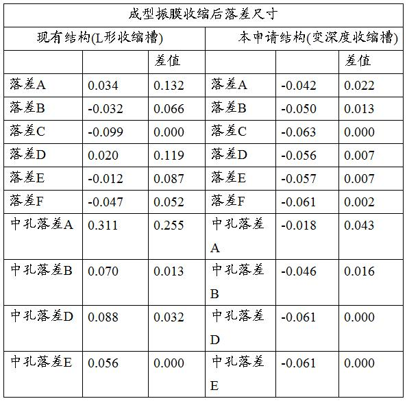
由上述结构尺寸的振膜模具设置可知,成型振膜后,振膜的收缩落差尺寸差小,使得振膜成型收缩平整性好,进一步改善振膜的品质。
与相关技术相比,本实用新型的振膜模具在模具本体的顶面凹陷形成呈环状的收缩槽,收缩槽环绕所述固定型芯部设置并折环型芯部相互间隔,收缩槽包括相对的两个第一边槽、相对的两个第二边槽以及连接相邻第一边槽和第二边槽的角部槽,且第一边槽、第二边槽及角部槽的槽深度相异,该结构的振膜模具因整个收缩槽的槽深非一致设置,可有效的控制振膜成型收缩后的振膜平整性,改善折环以及用于设置球顶的中孔位置(球项切边)落差一致性,有利于后续球顶、前盖等与振膜胶合装配的一致性,从而改善产品性能。
以上所述的仅是本实用新型的实施方式,在此应当指出,对于本领域的普通技术人员来说,在不脱离本实用新型创造构思的前提下,还可以做出改进,但这些均属于本实用新型的保护范围。
Claims (10)
- 一种振膜模具,其包括:模具本体,所述模具本体包括用于形成型芯结构的顶面、与所述顶面相对的底面以及连接所述顶面和所述底面的侧面;折环型芯部,所述折环型芯部呈环状,其由所述顶面凸出形成;中孔型芯部,所述中孔型芯部由所述顶面凸出形成并位于所述折环型芯部内侧;以及,固定型芯部,所述固定型芯部形成于所述顶面并位于所述折环型芯部外侧;其特征在于,所述振膜模具还包括:收缩槽,所述收缩槽呈环状,其由所述顶面向所述底面凹陷形成,所述收缩槽环绕所述固定型芯部设置并与所述折环型芯部相互间隔,所述收缩槽包括相对设置的两个第一边槽、相对设置的两个第二边槽以及连接相邻的所述第一边槽和所述第二边槽的角部槽,所述第一边槽、所述第二边槽及所述角部槽的槽深度相异。
- 根据权利要求1所述的振膜模具,其特征在于,所述角部槽的槽深度大于所述第一边槽及所述第二边槽的槽深度。
- 根据权利要求2所述的振膜模具,其特征在于,所述角部槽的深度为0.3-0.7mm。
- 根据权利要求2所述的振膜模具,其特征在于,所述收缩槽呈矩形结构,所述第一边槽位于所述收缩槽的长轴边,所述第二边槽位于所述收缩槽的短轴边,所述第二边槽的槽深度大于或等于所述第一边槽的槽深度。
- 根据权利要求4所述的振膜模具,其特征在于,所述第二边槽的槽深度为0.3-0.5mm。
- 根据权利要求5所述的振膜模具,其特征在于,所述第一边槽的槽深度为0.1-0.3mm。
- 根据权利要求1-6任一项所述的振膜模具,其特征在于,所述第一边槽、所述第二边槽以及所述角部槽的槽宽均相同。
- 根据权利要求7所述的振膜模具,其特征在于,所述收缩槽的槽宽为0.3-0.6mm。
- 根据权利要求1所述的振膜模具,其特征在于,所述收缩槽靠近所述侧面的一侧至所述侧面的距离大于或等于0.2mm。
- 根据权利要求1所述的振膜模具,其特征在于,所述角部槽呈圆弧形结构。
Applications Claiming Priority (2)
| Application Number | Priority Date | Filing Date | Title |
|---|---|---|---|
| CN202022586274.7U CN214419308U (zh) | 2020-11-10 | 2020-11-10 | 振膜模具 |
| CN202022586274.7 | 2020-11-10 |
Publications (1)
| Publication Number | Publication Date |
|---|---|
| WO2022099790A1 true WO2022099790A1 (zh) | 2022-05-19 |
Family
ID=78059972
Family Applications (1)
| Application Number | Title | Priority Date | Filing Date |
|---|---|---|---|
| PCT/CN2020/131400 Ceased WO2022099790A1 (zh) | 2020-11-10 | 2020-11-25 | 振膜模具 |
Country Status (2)
| Country | Link |
|---|---|
| CN (1) | CN214419308U (zh) |
| WO (1) | WO2022099790A1 (zh) |
Citations (8)
| Publication number | Priority date | Publication date | Assignee | Title |
|---|---|---|---|---|
| JP2000141423A (ja) * | 1998-11-05 | 2000-05-23 | Ricoh Co Ltd | プラスチック射出成形品及びその成形金型 |
| CN103347233A (zh) * | 2013-06-14 | 2013-10-09 | 歌尔声学股份有限公司 | 扬声器振膜 |
| CN207327575U (zh) * | 2017-10-24 | 2018-05-08 | 江西联创宏声电子股份有限公司 | 一种振膜成型模具及装置 |
| CN207825055U (zh) * | 2017-11-30 | 2018-09-07 | 歌尔科技有限公司 | 振膜成型模具座及振膜 |
| CN110913320A (zh) * | 2019-11-11 | 2020-03-24 | 歌尔股份有限公司 | 一种发声装置的振膜组件成型方法、振膜组件及发声单体 |
| CN210308619U (zh) * | 2019-07-04 | 2020-04-14 | 杭州藤仓橡胶有限公司 | 控制橡胶膜片外周变形的模具 |
| CN211941659U (zh) * | 2019-12-30 | 2020-11-17 | 瑞声科技(新加坡)有限公司 | 一种振膜成型模具 |
| CN112305805A (zh) * | 2019-07-30 | 2021-02-02 | 三星显示有限公司 | 显示装置和模具框架 |
-
2020
- 2020-11-10 CN CN202022586274.7U patent/CN214419308U/zh not_active Expired - Fee Related
- 2020-11-25 WO PCT/CN2020/131400 patent/WO2022099790A1/zh not_active Ceased
Patent Citations (8)
| Publication number | Priority date | Publication date | Assignee | Title |
|---|---|---|---|---|
| JP2000141423A (ja) * | 1998-11-05 | 2000-05-23 | Ricoh Co Ltd | プラスチック射出成形品及びその成形金型 |
| CN103347233A (zh) * | 2013-06-14 | 2013-10-09 | 歌尔声学股份有限公司 | 扬声器振膜 |
| CN207327575U (zh) * | 2017-10-24 | 2018-05-08 | 江西联创宏声电子股份有限公司 | 一种振膜成型模具及装置 |
| CN207825055U (zh) * | 2017-11-30 | 2018-09-07 | 歌尔科技有限公司 | 振膜成型模具座及振膜 |
| CN210308619U (zh) * | 2019-07-04 | 2020-04-14 | 杭州藤仓橡胶有限公司 | 控制橡胶膜片外周变形的模具 |
| CN112305805A (zh) * | 2019-07-30 | 2021-02-02 | 三星显示有限公司 | 显示装置和模具框架 |
| CN110913320A (zh) * | 2019-11-11 | 2020-03-24 | 歌尔股份有限公司 | 一种发声装置的振膜组件成型方法、振膜组件及发声单体 |
| CN211941659U (zh) * | 2019-12-30 | 2020-11-17 | 瑞声科技(新加坡)有限公司 | 一种振膜成型模具 |
Also Published As
| Publication number | Publication date |
|---|---|
| CN214419308U (zh) | 2021-10-19 |
Similar Documents
| Publication | Publication Date | Title |
|---|---|---|
| CN111294715A (zh) | 压电mems麦克风 | |
| CN104902401A (zh) | 发声器模组 | |
| WO2016165363A1 (zh) | 扬声器振动系统 | |
| CN109819389B (zh) | 振膜成型模具 | |
| CN109803219B (zh) | 振膜成型模具 | |
| WO2020140543A1 (zh) | 扬声器 | |
| WO2022099790A1 (zh) | 振膜模具 | |
| CN217677279U (zh) | 一种玻璃产品的成型模具 | |
| KR101353590B1 (ko) | 하나의 고분자 필름에서 강성도가 다르게 일체로 성형된 스피커용 진동판 | |
| CN101945311A (zh) | 一种骨传导扬声器 | |
| JPWO2017149984A1 (ja) | スピーカ | |
| WO2022000777A1 (zh) | 发声器件 | |
| US20240059599A1 (en) | Mold for molding glass product | |
| CN201479361U (zh) | 一种骨传导扬声器 | |
| CN203457314U (zh) | 音膜 | |
| WO2022111675A1 (zh) | 振膜单元和扬声器 | |
| US20250386144A1 (en) | Speaker | |
| WO2022000778A1 (zh) | 发声器件 | |
| CN224178300U (zh) | 一种双振膜发声喇叭 | |
| CN220359369U (zh) | 一种振膜成型模具 | |
| CN118354264B (zh) | 扬声器 | |
| CN215072962U (zh) | 一种新型球顶结构扬声器 | |
| JP3977829B2 (ja) | スピーカ用振動板及びこれを用いたスピーカ | |
| CN221263974U (zh) | 一种微型高音振膜 | |
| CN204652654U (zh) | 一种号筒式微型扬声器及终端设备 |
Legal Events
| Date | Code | Title | Description |
|---|---|---|---|
| 121 | Ep: the epo has been informed by wipo that ep was designated in this application |
Ref document number: 20961344 Country of ref document: EP Kind code of ref document: A1 |
|
| NENP | Non-entry into the national phase |
Ref country code: DE |
|
| 122 | Ep: pct application non-entry in european phase |
Ref document number: 20961344 Country of ref document: EP Kind code of ref document: A1 |