WO2022097662A1 - Food product processing device - Google Patents
Food product processing device Download PDFInfo
- Publication number
- WO2022097662A1 WO2022097662A1 PCT/JP2021/040501 JP2021040501W WO2022097662A1 WO 2022097662 A1 WO2022097662 A1 WO 2022097662A1 JP 2021040501 W JP2021040501 W JP 2021040501W WO 2022097662 A1 WO2022097662 A1 WO 2022097662A1
- Authority
- WO
- WIPO (PCT)
- Prior art keywords
- catalyst
- food processing
- ultraviolet light
- food
- processing apparatus
- Prior art date
Links
- 235000013305 food Nutrition 0.000 title claims abstract description 111
- 238000012545 processing Methods 0.000 title claims abstract description 73
- 239000012528 membrane Substances 0.000 claims abstract description 70
- 238000010521 absorption reaction Methods 0.000 claims abstract description 62
- 239000003054 catalyst Substances 0.000 claims description 151
- 239000010410 layer Substances 0.000 claims description 46
- GWEVSGVZZGPLCZ-UHFFFAOYSA-N Titan oxide Chemical compound O=[Ti]=O GWEVSGVZZGPLCZ-UHFFFAOYSA-N 0.000 claims description 41
- 239000002344 surface layer Substances 0.000 claims description 38
- 238000002441 X-ray diffraction Methods 0.000 claims description 21
- 239000000203 mixture Substances 0.000 claims description 11
- 229910044991 metal oxide Inorganic materials 0.000 claims description 7
- 150000004706 metal oxides Chemical class 0.000 claims description 7
- 230000003197 catalytic effect Effects 0.000 abstract 6
- 239000010408 film Substances 0.000 description 102
- 238000006243 chemical reaction Methods 0.000 description 48
- BDAGIHXWWSANSR-UHFFFAOYSA-N methanoic acid Natural products OC=O BDAGIHXWWSANSR-UHFFFAOYSA-N 0.000 description 36
- 239000007864 aqueous solution Substances 0.000 description 20
- 239000011248 coating agent Substances 0.000 description 20
- 238000000576 coating method Methods 0.000 description 20
- OSWFIVFLDKOXQC-UHFFFAOYSA-N 4-(3-methoxyphenyl)aniline Chemical compound COC1=CC=CC(C=2C=CC(N)=CC=2)=C1 OSWFIVFLDKOXQC-UHFFFAOYSA-N 0.000 description 18
- 235000019253 formic acid Nutrition 0.000 description 18
- 230000031700 light absorption Effects 0.000 description 17
- 239000000463 material Substances 0.000 description 13
- 230000006870 function Effects 0.000 description 12
- 230000001965 increasing effect Effects 0.000 description 11
- 238000013032 photocatalytic reaction Methods 0.000 description 10
- 240000004808 Saccharomyces cerevisiae Species 0.000 description 9
- 230000000052 comparative effect Effects 0.000 description 9
- 238000010304 firing Methods 0.000 description 8
- 239000007788 liquid Substances 0.000 description 8
- 238000006552 photochemical reaction Methods 0.000 description 8
- 239000000126 substance Substances 0.000 description 8
- 230000003993 interaction Effects 0.000 description 7
- 238000004528 spin coating Methods 0.000 description 7
- LRHPLDYGYMQRHN-UHFFFAOYSA-N N-Butanol Chemical compound CCCCO LRHPLDYGYMQRHN-UHFFFAOYSA-N 0.000 description 6
- 230000006866 deterioration Effects 0.000 description 6
- 238000000034 method Methods 0.000 description 6
- 239000011941 photocatalyst Substances 0.000 description 6
- 238000003756 stirring Methods 0.000 description 6
- VYPSYNLAJGMNEJ-UHFFFAOYSA-N Silicium dioxide Chemical compound O=[Si]=O VYPSYNLAJGMNEJ-UHFFFAOYSA-N 0.000 description 5
- 230000015572 biosynthetic process Effects 0.000 description 5
- 238000009792 diffusion process Methods 0.000 description 5
- 230000005284 excitation Effects 0.000 description 5
- 239000011259 mixed solution Substances 0.000 description 5
- 238000000295 emission spectrum Methods 0.000 description 4
- 238000011156 evaluation Methods 0.000 description 4
- 238000004519 manufacturing process Methods 0.000 description 4
- 238000005259 measurement Methods 0.000 description 4
- 230000000813 microbial effect Effects 0.000 description 4
- 239000000047 product Substances 0.000 description 4
- WEVYAHXRMPXWCK-UHFFFAOYSA-N Acetonitrile Chemical compound CC#N WEVYAHXRMPXWCK-UHFFFAOYSA-N 0.000 description 3
- -1 Lipid Hydroperoxide Chemical class 0.000 description 3
- 238000000862 absorption spectrum Methods 0.000 description 3
- 238000000354 decomposition reaction Methods 0.000 description 3
- 239000000796 flavoring agent Substances 0.000 description 3
- 235000019634 flavors Nutrition 0.000 description 3
- QSHDDOUJBYECFT-UHFFFAOYSA-N mercury Chemical compound [Hg] QSHDDOUJBYECFT-UHFFFAOYSA-N 0.000 description 3
- 229910052753 mercury Inorganic materials 0.000 description 3
- 230000008569 process Effects 0.000 description 3
- 239000002994 raw material Substances 0.000 description 3
- 238000001228 spectrum Methods 0.000 description 3
- OGIDPMRJRNCKJF-UHFFFAOYSA-N titanium oxide Inorganic materials [Ti]=O OGIDPMRJRNCKJF-UHFFFAOYSA-N 0.000 description 3
- 238000006276 transfer reaction Methods 0.000 description 3
- 238000000411 transmission spectrum Methods 0.000 description 3
- VEXZGXHMUGYJMC-UHFFFAOYSA-N Hydrochloric acid Chemical compound Cl VEXZGXHMUGYJMC-UHFFFAOYSA-N 0.000 description 2
- KFZMGEQAYNKOFK-UHFFFAOYSA-N Isopropanol Chemical compound CC(C)O KFZMGEQAYNKOFK-UHFFFAOYSA-N 0.000 description 2
- 229920002415 Pluronic P-123 Polymers 0.000 description 2
- RTAQQCXQSZGOHL-UHFFFAOYSA-N Titanium Chemical compound [Ti] RTAQQCXQSZGOHL-UHFFFAOYSA-N 0.000 description 2
- XLOMVQKBTHCTTD-UHFFFAOYSA-N Zinc monoxide Chemical compound [Zn]=O XLOMVQKBTHCTTD-UHFFFAOYSA-N 0.000 description 2
- YRKCREAYFQTBPV-UHFFFAOYSA-N acetylacetone Chemical compound CC(=O)CC(C)=O YRKCREAYFQTBPV-UHFFFAOYSA-N 0.000 description 2
- 238000006555 catalytic reaction Methods 0.000 description 2
- 150000001875 compounds Chemical class 0.000 description 2
- 230000007423 decrease Effects 0.000 description 2
- 238000004128 high performance liquid chromatography Methods 0.000 description 2
- 230000004298 light response Effects 0.000 description 2
- 230000001953 sensory effect Effects 0.000 description 2
- 230000008786 sensory perception of smell Effects 0.000 description 2
- 239000002356 single layer Substances 0.000 description 2
- 238000003980 solgel method Methods 0.000 description 2
- 239000007787 solid Substances 0.000 description 2
- 239000011949 solid catalyst Substances 0.000 description 2
- 239000000243 solution Substances 0.000 description 2
- 230000001954 sterilising effect Effects 0.000 description 2
- 239000000758 substrate Substances 0.000 description 2
- 239000010936 titanium Substances 0.000 description 2
- 229910052719 titanium Inorganic materials 0.000 description 2
- XLYOFNOQVPJJNP-UHFFFAOYSA-N water Substances O XLYOFNOQVPJJNP-UHFFFAOYSA-N 0.000 description 2
- MYMOFIZGZYHOMD-UHFFFAOYSA-N Dioxygen Chemical compound O=O MYMOFIZGZYHOMD-UHFFFAOYSA-N 0.000 description 1
- 240000007594 Oryza sativa Species 0.000 description 1
- 235000007164 Oryza sativa Nutrition 0.000 description 1
- 229910021536 Zeolite Inorganic materials 0.000 description 1
- 230000002745 absorbent Effects 0.000 description 1
- 239000002250 absorbent Substances 0.000 description 1
- 230000004075 alteration Effects 0.000 description 1
- 150000001491 aromatic compounds Chemical class 0.000 description 1
- 238000003149 assay kit Methods 0.000 description 1
- 230000002238 attenuated effect Effects 0.000 description 1
- 150000001555 benzenes Chemical class 0.000 description 1
- 239000005388 borosilicate glass Substances 0.000 description 1
- YHWCPXVTRSHPNY-UHFFFAOYSA-N butan-1-olate;titanium(4+) Chemical compound [Ti+4].CCCC[O-].CCCC[O-].CCCC[O-].CCCC[O-] YHWCPXVTRSHPNY-UHFFFAOYSA-N 0.000 description 1
- 125000002915 carbonyl group Chemical group [*:2]C([*:1])=O 0.000 description 1
- 239000000969 carrier Substances 0.000 description 1
- 239000007795 chemical reaction product Substances 0.000 description 1
- 239000003795 chemical substances by application Substances 0.000 description 1
- 238000004737 colorimetric analysis Methods 0.000 description 1
- 230000003247 decreasing effect Effects 0.000 description 1
- 230000007547 defect Effects 0.000 description 1
- 238000011161 development Methods 0.000 description 1
- 238000010586 diagram Methods 0.000 description 1
- HNPSIPDUKPIQMN-UHFFFAOYSA-N dioxosilane;oxo(oxoalumanyloxy)alumane Chemical compound O=[Si]=O.O=[Al]O[Al]=O HNPSIPDUKPIQMN-UHFFFAOYSA-N 0.000 description 1
- 230000002708 enhancing effect Effects 0.000 description 1
- 230000005281 excited state Effects 0.000 description 1
- 235000012041 food component Nutrition 0.000 description 1
- 239000005417 food ingredient Substances 0.000 description 1
- 125000000524 functional group Chemical group 0.000 description 1
- 150000002240 furans Chemical class 0.000 description 1
- 239000011521 glass Substances 0.000 description 1
- 230000001678 irradiating effect Effects 0.000 description 1
- 229920002521 macromolecule Polymers 0.000 description 1
- 244000005700 microbiome Species 0.000 description 1
- 238000001000 micrograph Methods 0.000 description 1
- 230000003287 optical effect Effects 0.000 description 1
- 239000005416 organic matter Substances 0.000 description 1
- TWNQGVIAIRXVLR-UHFFFAOYSA-N oxo(oxoalumanyloxy)alumane Chemical compound O=[Al]O[Al]=O TWNQGVIAIRXVLR-UHFFFAOYSA-N 0.000 description 1
- 230000002093 peripheral effect Effects 0.000 description 1
- 150000003222 pyridines Chemical class 0.000 description 1
- 238000012887 quadratic function Methods 0.000 description 1
- 230000006798 recombination Effects 0.000 description 1
- 238000005215 recombination Methods 0.000 description 1
- 230000004044 response Effects 0.000 description 1
- 235000009566 rice Nutrition 0.000 description 1
- 229910052710 silicon Inorganic materials 0.000 description 1
- 239000010703 silicon Substances 0.000 description 1
- 229910052814 silicon oxide Inorganic materials 0.000 description 1
- 150000003384 small molecules Chemical class 0.000 description 1
- 238000004611 spectroscopical analysis Methods 0.000 description 1
- 239000004094 surface-active agent Substances 0.000 description 1
- 239000010409 thin film Substances 0.000 description 1
- 229930192474 thiophene Natural products 0.000 description 1
- 150000003577 thiophenes Chemical class 0.000 description 1
- 238000012546 transfer Methods 0.000 description 1
- 238000002834 transmittance Methods 0.000 description 1
- 229910052724 xenon Inorganic materials 0.000 description 1
- FHNFHKCVQCLJFQ-UHFFFAOYSA-N xenon atom Chemical compound [Xe] FHNFHKCVQCLJFQ-UHFFFAOYSA-N 0.000 description 1
- 239000010457 zeolite Substances 0.000 description 1
- 239000011787 zinc oxide Substances 0.000 description 1
Images


Classifications
-
- B—PERFORMING OPERATIONS; TRANSPORTING
- B01—PHYSICAL OR CHEMICAL PROCESSES OR APPARATUS IN GENERAL
- B01J—CHEMICAL OR PHYSICAL PROCESSES, e.g. CATALYSIS OR COLLOID CHEMISTRY; THEIR RELEVANT APPARATUS
- B01J21/00—Catalysts comprising the elements, oxides, or hydroxides of magnesium, boron, aluminium, carbon, silicon, titanium, zirconium, or hafnium
- B01J21/06—Silicon, titanium, zirconium or hafnium; Oxides or hydroxides thereof
- B01J21/063—Titanium; Oxides or hydroxides thereof
-
- A—HUMAN NECESSITIES
- A23—FOODS OR FOODSTUFFS; TREATMENT THEREOF, NOT COVERED BY OTHER CLASSES
- A23L—FOODS, FOODSTUFFS, OR NON-ALCOHOLIC BEVERAGES, NOT COVERED BY SUBCLASSES A21D OR A23B-A23J; THEIR PREPARATION OR TREATMENT, e.g. COOKING, MODIFICATION OF NUTRITIVE QUALITIES, PHYSICAL TREATMENT; PRESERVATION OF FOODS OR FOODSTUFFS, IN GENERAL
- A23L3/00—Preservation of foods or foodstuffs, in general, e.g. pasteurising, sterilising, specially adapted for foods or foodstuffs
- A23L3/26—Preservation of foods or foodstuffs, in general, e.g. pasteurising, sterilising, specially adapted for foods or foodstuffs by irradiation without heating
- A23L3/28—Preservation of foods or foodstuffs, in general, e.g. pasteurising, sterilising, specially adapted for foods or foodstuffs by irradiation without heating with ultraviolet light
-
- A—HUMAN NECESSITIES
- A23—FOODS OR FOODSTUFFS; TREATMENT THEREOF, NOT COVERED BY OTHER CLASSES
- A23L—FOODS, FOODSTUFFS, OR NON-ALCOHOLIC BEVERAGES, NOT COVERED BY SUBCLASSES A21D OR A23B-A23J; THEIR PREPARATION OR TREATMENT, e.g. COOKING, MODIFICATION OF NUTRITIVE QUALITIES, PHYSICAL TREATMENT; PRESERVATION OF FOODS OR FOODSTUFFS, IN GENERAL
- A23L5/00—Preparation or treatment of foods or foodstuffs, in general; Food or foodstuffs obtained thereby; Materials therefor
- A23L5/30—Physical treatment, e.g. electrical or magnetic means, wave energy or irradiation
-
- B01J35/39—
-
- B01J35/40—
-
- B—PERFORMING OPERATIONS; TRANSPORTING
- B01—PHYSICAL OR CHEMICAL PROCESSES OR APPARATUS IN GENERAL
- B01J—CHEMICAL OR PHYSICAL PROCESSES, e.g. CATALYSIS OR COLLOID CHEMISTRY; THEIR RELEVANT APPARATUS
- B01J37/00—Processes, in general, for preparing catalysts; Processes, in general, for activation of catalysts
- B01J37/02—Impregnation, coating or precipitation
- B01J37/0215—Coating
-
- B—PERFORMING OPERATIONS; TRANSPORTING
- B01—PHYSICAL OR CHEMICAL PROCESSES OR APPARATUS IN GENERAL
- B01J—CHEMICAL OR PHYSICAL PROCESSES, e.g. CATALYSIS OR COLLOID CHEMISTRY; THEIR RELEVANT APPARATUS
- B01J37/00—Processes, in general, for preparing catalysts; Processes, in general, for activation of catalysts
- B01J37/02—Impregnation, coating or precipitation
- B01J37/03—Precipitation; Co-precipitation
- B01J37/031—Precipitation
- B01J37/033—Using Hydrolysis
-
- C—CHEMISTRY; METALLURGY
- C12—BIOCHEMISTRY; BEER; SPIRITS; WINE; VINEGAR; MICROBIOLOGY; ENZYMOLOGY; MUTATION OR GENETIC ENGINEERING
- C12C—BEER; PREPARATION OF BEER BY FERMENTATION; PREPARATION OF MALT FOR MAKING BEER; PREPARATION OF HOPS FOR MAKING BEER
- C12C11/00—Fermentation processes for beer
- C12C11/003—Fermentation of beerwort
-
- C—CHEMISTRY; METALLURGY
- C12—BIOCHEMISTRY; BEER; SPIRITS; WINE; VINEGAR; MICROBIOLOGY; ENZYMOLOGY; MUTATION OR GENETIC ENGINEERING
- C12H—PASTEURISATION, STERILISATION, PRESERVATION, PURIFICATION, CLARIFICATION OR AGEING OF ALCOHOLIC BEVERAGES; METHODS FOR ALTERING THE ALCOHOL CONTENT OF FERMENTED SOLUTIONS OR ALCOHOLIC BEVERAGES
- C12H1/00—Pasteurisation, sterilisation, preservation, purification, clarification, or ageing of alcoholic beverages
Definitions
- This disclosure relates to food processing equipment.
- Patent Document 1 describes a method for producing a brewed product using a photocatalyst.
- this production method when sterilizing microorganisms in a brewed product, the brewed product placed in a tank is stirred by a stirring member at room temperature, and excitation light is applied to a photocatalyst supported on the surface of a predetermined member such as the stirring member. Is irradiated.
- Patent Document 1 describes a microbial sterilizer 300 used for producing sake, which is an example of a method for producing this brewed product.
- the light source 310 of the excitation light is arranged outside the tank 301.
- an anatase-type titanium oxide film is formed on the surface of the stirring blade 309.
- the present disclosure provides a food processing apparatus that is advantageous from the viewpoint of increasing the reaction rate while suppressing the deterioration of the food when processing the food using light.
- the food processing equipment of the present disclosure is A container with space for storing food, A catalyst membrane having an active surface in contact with the space, A light source that is arranged at a position closer to the main surface of the catalyst film located on the opposite side of the active surface than the active surface in the thickness direction of the catalyst film and emits ultraviolet light toward the catalyst film. , Equipped with The absorption rate of the ultraviolet light in the catalyst membrane is 50% or more.
- the food processing apparatus of the present disclosure is advantageous from the viewpoint of increasing the reaction rate while suppressing the deterioration of food.
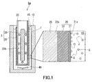
- FIG. 1 is a cross-sectional view schematically showing the food processing apparatus of the first embodiment.
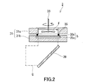
- FIG. 2 is a cross-sectional view of an apparatus for evaluating the characteristics of catalyst membranes having various thicknesses.
- FIG. 3 is an intensity spectrum of light used in the apparatus shown in FIG.
- FIG. 4A is a graph showing the relationship between the reaction rate constant of the decomposition reaction of formic acid and the thickness of the catalyst membrane.
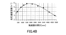
- FIG. 4B is a graph showing the relationship between the reaction rate constant of the decomposition reaction of formic acid and the thickness of the catalyst membrane.
- FIG. 4C is a graph showing the relationship between the reaction rate constant of the decomposition reaction of formic acid and the thickness of the catalyst membrane.
- FIG. 5 is a graph showing the relationship between the upper and lower limit values of the thickness of the catalyst membrane and the wavelength of the excitation light.
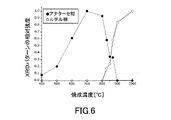
- FIG. 6 is a graph showing the relationship between the relative intensities of the anatase phase and the rutile phase and the firing temperature in the X-ray diffraction (XRD) pattern of the catalyst film.
- FIG. 7 is a diagram showing a microbial sterilizer according to the prior art.
- the present inventors when the excitation light containing ultraviolet light passes through the food contained in the container before it enters the photocatalyst, it is caused by the ultraviolet light of the component contained in the food, which should not occur originally. It was found that alteration or deterioration could occur. Therefore, as a result of diligent studies, the present inventors have made it possible for the ultraviolet light emitted from the light source to enter the catalyst film from the main surface opposite to the active surface of the catalyst film, thereby altering the components contained in the food. Alternatively, it was newly found to be advantageous from the viewpoint of preventing deterioration. The present inventors further studied and newly found that the reaction rate of the reaction for processing food can be increased by satisfying a predetermined condition for the catalyst film. Based on such new findings, the present inventors have completed the food processing apparatus of the present disclosure.
- FIG. 1 is a cross-sectional view schematically showing the food processing apparatus 1a of the first embodiment.
- the food processing apparatus 1a includes a container 10, a catalyst film 20, and a light source 30.
- the container 10 has a space 15 for accommodating the food F.
- Food F may be a food raw material.
- the catalyst membrane 20 has an active surface 21a in contact with the space 15.
- the light source 30 is arranged at a position closer to the main surface 22a of the catalyst film 20 located on the opposite side of the active surface 21a than the active surface 21a in the thickness direction of the catalyst film 20.
- the light source 30 emits ultraviolet light U toward the catalyst film 20.
- the absorption rate of ultraviolet light U in the catalyst film 20 is 50% or more.
- the excitons that reach this interface cause a charge transfer reaction between the oxygen molecule, the water molecule, and the reaction substrate contained in the food F and the catalyst membrane 20, and generate an active species.
- the photochemical reaction required for the processing of food F proceeds selectively.
- the excitons generated by the interaction between the catalyst film 20 and the ultraviolet light U may be charged-separated and behave as carriers such as electrons and holes.
- Foods containing food ingredients are sensitive to UV light irradiation. When the food is irradiated with ultraviolet light, the food is deteriorated or deteriorated, and a strange odor such as putrefactive odor, bad odor, and artificial odor, which is different from the original flavor of the food, may be felt. Flavor, taste, and texture are the three major elements of food. Among them, flavor is an important factor. Therefore, the generation of such an offensive odor can be a factor that greatly reduces the value of food.
- the food processing apparatus 1a most of the light amount of the ultraviolet light U is absorbed by the catalyst film 20 before the ultraviolet light U reaches the food F, so that the food F is irradiated with high-intensity ultraviolet light. Hateful.
- the absorption rate of the ultraviolet light U in the catalyst film 20 can be changed according to the wavelength of the ultraviolet light U emitted from the light source 30. Therefore, various types of light sources can be used as the light source 30. As described above, according to the food processing apparatus 1a, deterioration or deterioration of the food due to ultraviolet light can be prevented, and a desired reaction mainly for food processing can be promoted.
- the photocatalytic reaction that occurs as a result of the interaction of light with a solid catalyst or the like is also a photochemical reaction.
- an organic photochemical reaction In order to distinguish between a photocatalytic reaction that occurs as a result of the interaction between a solid catalyst and light and a photochemical reaction that occurs as a result of the direct interaction between an organic molecule and light, the latter is referred to as an "organic photochemical reaction" here.
- the processing of food F performed by using the food processing apparatus 1a is not limited to specific processing. This processing may be a processing for sterilizing the food F, or may be a processing for changing a component contained in the food F into another component.
- the food processing apparatus 1a may be used for brewing, or may be used for food production and food processing other than brewing.
- the thickness of the catalyst film 20 is adjusted so that the absorption rate of ultraviolet light U in the catalyst film 20 is 50% or more.
- the thickness of the catalyst membrane 20 can be determined, for example, based on the interference pattern appearing in the transmission spectrum of the catalyst membrane 20.
- the absorption rate of ultraviolet light U in the catalyst film 20 can be determined by, for example, the following method.
- the emission spectrum of the light source 30 is acquired, and the wavelength range ⁇ corresponding to the full width at half maximum with respect to the maximum light intensity in the emission spectrum is specified.
- the absorption spectrum of the catalyst membrane 20 is measured using a spectrophotometer. Obtain the integral value I I of the light intensity of the emission spectrum in the wavelength range ⁇ .
- the integrated value I A of the light intensity absorbed by the catalyst film 20 in the wavelength range is obtained.
- the absorption rate A is determined from the equation (1) based on the integral value I I and the integral value I A.
- a [%] 100 ⁇ I A / I I formula (1)
- the absorption rate of ultraviolet light U in the catalyst film 20 may be 55% or more, 60% or more, or 70% or more.
- the absorption rate of the ultraviolet light U in the catalyst film 20 may be 100%, 98% or less, or 95% or less.
- the ultraviolet light incident on the catalyst film has a large light intensity when it propagates through a part of the catalyst film. Decay. Therefore, it is difficult for the ultraviolet light to propagate to the main surface of the catalyst film on the opposite side of the incident surface of the catalyst film to which the ultraviolet light is incident.
- the interaction between the ultraviolet light and the catalyst film is weak and the absorption coefficient ⁇ of the substance forming the catalyst film is small, the ultraviolet light incident on the catalyst film is on the opposite side of the incident surface of the catalyst film on which the ultraviolet light is incident. Propagates to the main surface of the catalyst film.
- the light intensity of the ultraviolet light is not so attenuated, and the ultraviolet light leaks to the outside of the catalyst film.
- the catalyst film 20 preferably has an absorption coefficient ⁇ [cm -1 ] in a predetermined range with respect to the wavelength ⁇ of the ultraviolet light U.
- the absorption coefficient ⁇ of the ultraviolet light U at the wavelength ⁇ is, for example, 1971.8 cm -1 when the wavelength ⁇ is 365 nm, 7347.3 cm -1 when the wavelength ⁇ is 350 nm, and the wavelength ⁇ is 330 nm. When it is, it is 18039.7 cm -1 .
- the absorption coefficient ⁇ is, for example, 1971.8 cm -1 to 18039.7 cm -1 .
- the attenuation of the light intensity of the ultraviolet light U in the catalyst film 20 can be easily adjusted to a desired degree.
- the wavelength of the ultraviolet light U emitted from the light source 30 is not limited to a specific value, and is, for example, 320 nm to 375 nm. As a result, the ultraviolet light U is appropriately absorbed in the catalyst film 20.
- the light source 30 is not limited to a specific light source, and may be, for example, a high-pressure mercury lamp, a low-pressure mercury lamp, a fluorescent lamp type light source containing a fluorescent agent, or a light emitting diode (LED).
- the light source 30 is preferably a monochromatic light source. In this case, since the wavelength range of the ultraviolet light U is narrow, it is easy to adjust the thickness of the catalyst film 20.
- the thickness of the catalyst membrane 20 there are upper and lower limits to the thickness of the catalyst membrane 20. This is because the emission spectrum of the light source 30 is not expressed as a delta function, but has a finite spectrum width, and the ultraviolet light absorption spectrum, which is the ultraviolet light response characteristic of the catalyst film 20, is a continuous function.
- the thickness of the catalyst film 20 is, for example, equal to or greater than the value of the function F ( ⁇ ) shown in the following equation (3) with the wavelength of the ultraviolet light U as a variable, and the following equation with the wavelength of the ultraviolet light U as a variable. It is equal to or less than the value of the function G ( ⁇ ) shown in (4).
- the ultraviolet light U is well absorbed in the catalyst film 20, a large number of excitons are generated, and the catalyst film 20 is diffused, so that the reaction rate of the reaction for processing the food F tends to increase.
- the intensity of the transmitted light due to the incident of the ultraviolet light U on the catalyst film 20 tends to decrease, and the food F can be prevented from being deteriorated or deteriorated.
- the catalyst membrane 20 may be a membrane having a plurality of layers or a single-layer membrane. As shown in FIG. 1, the catalyst membrane 20 has, for example, a surface layer 21 and an absorption layer 22.
- the surface layer 21 has an active surface 21a.
- the absorption layer 22 has a main surface 22a.
- the absorption layer 22 plays a role of absorbing ultraviolet light U to generate excitons and moving the generated excitons toward the active surface 21a.
- the surface layer 21 plays a role of causing a charge transfer reaction at the interface between the active surface 21a and the food F.
- the absorption layer 22 can function as an absorption medium for ultraviolet light U.
- the number of charge transfer reactions that occur at the interface between the active surface 21a and the food F does not exceed the number of photons absorbed by the catalyst membrane 20. Therefore, in order to increase the reaction rate of the reaction for processing the food F, it is desirable that the ultraviolet light U incident on the catalyst film 20 is sufficiently absorbed inside the absorption layer 22.
- the thickness of the absorption layer 22 is adjusted so that the thickness of the catalyst membrane 20 is F ( ⁇ ) or more.
- the absorption layer 22 can also function as an exciton conduction medium.
- Exciton generated inside the absorption layer 22 can diffuse inside the absorption layer 22 and reach the interface between the active surface 21a and the food F in a finite life ⁇ (second) of several nanoseconds to several tens of nanoseconds. .. Exciton that could not reach this interface is inactivated by the recombination of excited electrons and holes. In this case, the light energy used to generate excitons is converted into thermal energy without causing a chemical reaction, which is wasted. Therefore, for example, the thickness of the absorption layer 22 is adjusted so that the thickness of the catalyst membrane 20 is G ( ⁇ ) or less.
- the diffusion rate of excitons in the catalyst membrane 20 is expressed as v [ ⁇ m / sec], the maximum diffusion distance of excitons can be approximated to ⁇ ⁇ v.
- ⁇ reflects the excited state dynamics of excitons and is affected by factors such as the electronic state and defect density of the material.
- the crystalline phase in the catalyst membrane 20 can also affect ⁇ .
- the surface layer 21 has an active surface 21a and promotes a catalytic reaction.
- the elementary process of catalytic reaction is a chemical reaction that occurs on the surface of a solid. Therefore, the performance as a catalyst is easily determined by the fine structure on the active surface 21a, not by the structure as a bulk.
- the active surface 21a has a predetermined fine structure such as surface unevenness. As a result, the surface area of the active surface 21a tends to increase. As a result, by sufficiently increasing the substance transport rate of the component C contained in the food F to the active surface 21a, the reaction rate of the reaction required for the processing of the food F can be more reliably increased.
- each of the thickness of the surface layer 21 and the thickness of the absorption layer 22 is not limited to a specific value as long as the absorption rate of the ultraviolet light U in the catalyst film 20 is 50% or more.
- the thickness of the absorption layer 22 is larger than, for example, the thickness of the surface layer 21.
- the absorption layer 22 can satisfactorily absorb the ultraviolet light U.
- the thickness of the surface layer 21 may be, for example, several nanometers to several tens of nanometers. If the surface layer 21 is several nanometers thick, the surface layer 21 can be formed, for example, as a single layer. When the thickness of the surface layer 21 is several tens of nanometers, the surface layer 21 can be formed as, for example, a plurality of layers.
- each of the thickness of the surface layer 21 and the thickness of the absorption layer 22 can be determined based on, for example, an electron microscope image of a cross section of the catalyst membrane 20. In this case, each of the thickness of the surface layer 21 and the thickness of the absorption layer 22 can be determined as an arithmetic mean value of 10 or more randomly selected thicknesses.
- the catalyst membrane 20 contains, for example, a metal oxide. As a result, the ultraviolet light U is well absorbed in the catalyst film 20, and the reaction rate of the reaction for processing the food F can be more reliably increased.
- the metal oxide contained in the catalyst film 20 is not limited to a specific metal oxide, and may be, for example, titanium oxide, zinc oxide, silicon oxide, aluminum oxide, or zeolite. In addition, in this specification, an oxide containing silicon is included in "metal oxide”.
- the metal oxide contained in the catalyst membrane 20 may have a composition of Tim On. This composition satisfies the conditions of 1 ⁇ m ⁇ 2 and 2 ⁇ n ⁇ 3. In this case, the reaction rate of the reaction for processing the food F can be more reliably increased.
- the material forming the surface layer 21 and the material forming the absorption layer 22 may be the same type of material or different types of materials.
- the material forming the surface layer 21 and the material forming the absorption layer 22 are different materials, it is easy to enhance the function of the absorption layer 22 while further enhancing the function of the surface layer 21.
- the relative strength I KA of the anatase phase and the relative strength I KR of the rutile phase in the XRD pattern of the absorption layer 22 satisfy, for example, 0.6 ⁇ I KA ⁇ 1.0 and I KR ⁇ 0.2.
- the surface layer 21 contains, for example, an anatase phase and substantially no rutile phase. Thereby, the reaction rate of the reaction for processing the food F can be further increased.
- the fact that the rutile phase is not substantially contained means that the relative intensity of the rutile phase can be regarded as zero in the XRD pattern.
- the maximum diffusion distance of excitons has a simple positive correlation with the relative intensity I KA of the anatase phase in the XRD pattern of the absorption layer 22 and a simple negative correlation with the relative intensity I KR of the rutile phase.
- the absorption layer 22 satisfies the conditions of 0.6 ⁇ I KA ⁇ 1.0 and I KR ⁇ 0.2.
- the relative intensity I HA of the anatase phase in the X-ray diffraction pattern of the surface layer 21 may satisfy the condition of 0 ⁇ I HA ⁇ 0.6. As a result, the specific surface area of the surface layer 21 tends to increase, and the reaction rate of the reaction for processing the food F tends to increase.
- the relative strength I KA of the anatase phase and the relative strength I KR of the rutile phase in the XRD pattern of the absorption layer 22 may satisfy the conditions of 0 ⁇ I KA ⁇ 0.6 and I KR ⁇ 0.2.
- the relative intensity I HA of the anatase phase in the X-ray diffraction pattern of the surface layer 21 may satisfy the condition of 0.6 ⁇ I HA ⁇ 1.0.
- the relative intensity I HR of the rutile phase in the X-ray diffraction pattern of the surface layer 21 may satisfy the condition of I KR ⁇ 0.2.
- the food processing apparatus 1a further includes, for example, a support 25.
- the support 25 is arranged at a position closer to the main surface 22a than the active surface 21a in the thickness direction of the catalyst film 20 and supports the catalyst film 20.
- the catalyst membrane 20 can be stably present in the food processing apparatus 1a.
- the material of the support 25 is not limited to a specific material, and is, for example, glass.
- the support 25 typically has a low light response characteristic to the ultraviolet light U and a high transmittance to the ultraviolet light U.
- Examples of materials for the support 25 are quartz glass and borosilicate glass.
- the shape of the support 25 is not limited to a specific shape as long as it can support the catalyst membrane 20.
- the support 25 has, for example, a cavity 25h.
- the light source 30 is arranged in, for example, the cavity 25h.
- the support 25 is, for example, tubular.
- the support 25 may be a hollow spherical shape or a hollow polyhedral shape.
- the food processing apparatus 1a may further include a stirrer 40.
- the stirrer 40 includes, for example, a rotating shaft and a stirring blade attached to the rotating shaft.
- Mass transfer includes diffusion movement accompanying a concentration gradient and convection movement that moves along with the flow of the field.
- the operation of the stirrer 40 increases the substance transport rate in the food F.
- the concentration of the component C contained in the food is likely to be kept high at the interface between the catalyst membrane 20 and the food F.
- the operation of the stirrer 40 can promote the development of the field flow of food F in the space 15 of the container 10.
- the axis of rotation of the stirrer 40 can be inserted from above or below the container 10.
- the light source 2 with a catalyst includes a catalyst film 20 and a light source 30.
- the catalyst-equipped light source 2 is used in the food processing apparatus 1a.
- the food processing apparatus of the present disclosure will be described in more detail by way of examples.
- the food processing apparatus of the present disclosure is not limited to the following examples.
- Example 1 A benchtop type food processing apparatus according to Example 1 having the same configuration as the food processing apparatus 1a shown in FIG. 1 was produced.
- the container of this food processing appliance was capable of accommodating 300 cm 3 of liquid.
- a quartz glass sleeve was used as the support.
- the sleeve had a cylindrical shape with a length of 210 mm and an outer diameter of 54 mm, and one end in the length direction of the sleeve was closed.
- a high-pressure mercury lamp HL100 manufactured by Sen Special Light Source Co., Ltd. was placed inside the sleeve as a light source.
- the power consumption of the light source was 100 W.
- the bulb length of the light source was 12.7 cm, and the length of the light emitting portion thereof was 8.5 cm.
- the wavelength of the emitted light of the light source was 365 nm.
- the light intensity of the emitted light of the light source decreased in inverse proportion to the distance from the light source, and the light intensity of the emitted light at a position 20 mm away from the lamp surface was 100 mW / cm 2 .
- a magnetic stirrer was placed on the bottom surface of the container.
- a catalyst membrane was formed on the outer surface of the sleeve by the sol-gel method. While stirring 0.092 mol (21 g) of titanium ethoxydo, 14.6 cm 3 of hydrochloric acid having a mass concentration of 20% was gradually added to the titanium ethoxydo to obtain a mixed solution. A solution of 6 g of the surfactant Pluronique P123 and 74 cm 3 of 1-butanol was added to the obtained mixed solution, and the mixture was stirred for 3 hours to obtain sol A. The average molecular weight of Pluronic P123 was 5800. Sol A was applied to the outer surface of the sleeve by spin coating at 3000 rpm (rpm) and 30 seconds to form a coating.
- This coating film was fired in an electric furnace at 500 ° C. for 2 hours to obtain a catalyst thin film having a thickness of about 400 nm to 500 nm.
- the process of forming the coating film and firing the coating film was repeated four times to obtain an absorption layer according to Example 1.
- Sol A was applied onto the absorbent layer according to Example 1 by spin coating at 3000 rpm (rpm) and 30 seconds to form a coating film.
- This coating film was fired in an electric furnace at 500 ° C. for 2 hours to form the surface layer according to Example 1 to obtain a catalyst film according to Example 1 composed of an absorption layer and a surface layer.
- a transmission spectrum in the wavelength range of 200 nm to 2500 nm of the catalyst membrane according to Example 1 was obtained. From the interference pattern appearing in this transmission spectrum, the thickness of the catalyst film according to Example 1 was obtained using a film thickness calculation program provided by JASCO Corporation. As a result, the thickness of the catalyst membrane according to Example 1 was 2028.0 nm.
- the light absorption rate of the catalyst film according to Example 1 at wavelengths of 365 nm, 350 nm, and 330 nm was determined.
- the light absorption rate of the catalyst membrane according to Example 1 was as shown in Table 1.
- a 10% by mass yeast aqueous solution was placed in the container of the food processing apparatus according to Example 1.
- the temperature of the yeast aqueous solution was adjusted to 5 ° C.
- the light source of the food processing apparatus was turned on for 96 hours, and then the light source was turned off.
- the yeast aqueous solution was stirred by rotating the magnetic stirrer while the light source was lit.
- the Lipid Hydroperoxide Assay Kit provided by Funakoshi
- the lipid peroxide concentration in the liquid sample collected from the yeast aqueous solution immediately before the light source was turned on and the yeast aqueous solution immediately after the light source was turned off was determined according to the colorimetric method. As a result, it was confirmed that the concentration of lipid peroxide, which is a reaction product, increased immediately after the light source was turned off and compared with immediately before the light source was turned on.
- a formic acid aqueous solution having a concentration of 10 mg / liter was placed as a model food raw material aqueous solution in the container of the food processing apparatus according to Example 1.
- the temperature of the aqueous formic acid solution was adjusted to room temperature.
- the light source was turned on, the light source was turned off after a lapse of a predetermined time, and a part of the formic acid aqueous solution was collected as a liquid sample.
- “h” means time.
- the amount of formic acid reacted was 3.7 mg / liter.
- Example 2 Except for the following points, the food processing apparatus according to Example 2 was produced in the same manner as in Example 1. 0.025 mol (2.52 g) of acetylacetone and 0.05 mol (17.50 g) of titanium butoxide were mixed in this order with 32 cm 3 of 1-butanol and stirred at room temperature for 1 hour to obtain a mixed solution. A mixture of 0.15 mol (9.05 g) of isopropanol and 3.64 cm 3 of water was mixed with this mixed solution, and the mixture was further stirred for 1 hour to obtain a mixed solution. 0.04 mol (1.66 g) of acetonitrile was added to this mixture, and the mixture was stirred for 1 hour to obtain sol B.
- Sol B is applied to the surface of the absorption layer by spin coating at 6000 rpm for 30 seconds and fired in an electric furnace at 600 ° C. for 2 hours to form the surface layer according to Example 2, which is composed of the absorption layer and the surface layer.
- the catalyst membrane according to Example 2 was obtained.
- the thickness of the catalyst membrane according to Example 2 was measured in the same manner as the catalyst membrane according to Example 1. As a result, the thickness of the catalyst membrane according to Example 2 was 2156.0 nm.
- an ultraviolet-visible near-infrared spectrophotometer V-770 the light absorption rate of the catalyst film according to Example 2 at wavelengths of 365 nm, 350 nm, and 330 nm was determined. As a result, the light absorption rate of the catalyst membrane according to Example 2 was as shown in Table 2.
- the light absorption rate of the catalyst film according to Example 2 at these wavelengths was 50% or more.
- a food processing apparatus according to Comparative Example 1 was produced in the same manner as in Example 1 except for the following points.
- the catalyst film according to Comparative Example 1 was formed in the same manner as in Example 1 except that the layer corresponding to the absorption layer according to Example 1 was not formed.
- the thickness of the catalyst membrane according to Comparative Example 1 was 79.7 nm when measured by the same method as that for the catalyst membrane according to Example 1.
- an ultraviolet-visible near-infrared spectrophotometer V-770 the light absorption rate of the catalyst film according to Comparative Example 1 at wavelengths of 365 nm, 350 nm, and 330 nm was determined.
- the light absorption rate of the catalyst membrane according to Comparative Example 1 was as shown in Table 3.
- the light absorption rate of the catalyst membrane according to Comparative Example 1 at these wavelengths was less than 50%.
- the reaction rate constant of the photocatalytic reaction in the food processing apparatus according to Examples 1 and 2 was higher than the reaction rate constant of the photocatalytic reaction in the food processing apparatus according to Comparative Example 1. It is understood that the light absorption rate of the catalyst film at the wavelength of ultraviolet light is 50% or more, which is advantageous for increasing the reaction rate constant of the photocatalytic reaction.
- the device 3 shown in FIG. 2 was manufactured.
- the device 3 includes a container 31, a stirrer 33, an O-ring 35, a sample S, and a mirror 38.
- the container 31 had a plate-shaped upper member 31a having a through hole in the center and a plate-shaped lower member 31b having a recess in the center.
- the sample S had a support plate 25s made of quartz glass and a catalyst film 20s formed on the support plate 25s.
- the support plate 25s had a square shape of 30 mm square in a plan view.
- the sample S was housed in the recess of the lower member 31b so that the catalyst membrane 20s was located above the support plate 25s.
- An O-ring 35 is arranged between the upper member 31a and the lower member 31b, and the upper member 31a and the lower member 31b are assembled to form the container 31.
- the O-ring 35 was in contact with the edge in contact with the central opening and the peripheral edge of the catalyst membrane 20s on the lower surface of the upper member 31a, and sealed these gaps.
- the mirror 38 was arranged below the container 31 so as to guide the ultraviolet light U incident on the mirror 38 in the horizontal direction to the sample S.
- the catalyst membrane 20s in sample S was formed by the sol-gel method.
- a sol was prepared under the same conditions as sol A, and this sol was applied to the support plate 25s by spin coating to form a coating film.
- This coating film was fired in an electric furnace at 500 ° C. for 2 hours to obtain a catalyst film 20s.
- nine samples S having catalyst films 20s having different thicknesses were prepared.
- the thickness of the catalyst membrane 20s in these samples was 411.5 nm, 828.0 nm, 1151.0 nm, 1511.5 nm, 2156.0 nm, 2826.5 nm, 3490.5 nm, 4154.5 nm, and 4819.0 nm. rice field.
- the thickness of the catalyst membrane 20s in each sample S was determined in the same manner as the thickness of the catalyst membrane according to Example 1.
- a xenon lamp MAX303 manufactured by Asahi Spectroscopy and a bandpass filter for monochromaticization three types of monochromatic ultraviolet light having center wavelengths of 330 nm, 350 nm, and 365 nm were adjusted.
- the light intensity spectrum of the monochromatic ultraviolet light is shown in FIG. The bandwidth of these ultraviolet lights was a center wavelength of ⁇ 5 nm.
- the light intensity of the monochromatic ultraviolet light was adjusted so that the light intensity on the irradiation surface of the ultraviolet light U was made uniform by using a light intensity spatially uniform lens, which is a rod lens manufactured by Asahi Optical Co., Ltd.
- the light intensity on the surface of the catalyst film 20s was 3 mW / cm 2 , which was uniform over the entire surface of the catalyst film 20s.
- a formic acid aqueous solution having a concentration of 10 mg / liter was placed inside the container 31.
- the volume of the formic acid aqueous solution was 5 ml.
- the formic acid aqueous solution was stirred by rotating the stirrer 33.
- the ultraviolet light U adjusted as described above was guided to the bottom surface of the container 31 and passed through the support 25s to irradiate the catalyst film 20s.
- the concentration of formic acid in the liquid sample collected from the formic acid aqueous solution after a lapse of a predetermined time after irradiating the catalyst film 20s with ultraviolet light U was measured by HPLC. Using the data on the reaction rate obtained from this measurement result and the first-order reaction rate equation, the reaction rate constant of the photocatalytic reaction was obtained.
- the results of using three types of monochromatic ultraviolet light having center wavelengths of 365 nm, 350 nm, and 330 nm for adjusting the ultraviolet light U are shown in FIGS. 4A, 4B,
- FIGS. 4A, 4B, and 4C the reaction rate constants with respect to the thickness of the catalyst membrane are plotted.
- the plots in FIGS. 4A, 4B, and 4C had an upwardly convex peak shape.
- the longer the wavelength of the ultraviolet light U the more the peak of the plot tended to shift to the longer wavelength side.
- the data were least squares fitted using the Giddings peak function.
- the functions obtained by this fitting are shown as solid graphs in FIGS. 4A, 4B, and 4C.
- the upper limit value and the lower limit value of the wavelength showing the reaction rate constant of 70% or more of the maximum value were specified.
- FIG. 5 shows the relationship between the obtained upper limit value and lower limit value and the wavelength of the ultraviolet light U.
- the relationship between the upper limit and the wavelength of the ultraviolet light U and the relationship between the lower limit and the wavelength of the ultraviolet light U were approximated by a quadratic function A + B ⁇ ⁇ + C ⁇ ⁇ 2 . From this approximation, F ( ⁇ ) represented by the above equation (3) and G ( ⁇ ) represented by the equation (4) were obtained.
- Sol A is applied onto a predetermined substrate by spin coating to form a coating film, and this coating film is fired for 2 hours in an electric furnace set to a predetermined temperature in the range of 400 ° C. to 1000 ° C. for XRD measurement.
- a film was formed.
- An XRD pattern of an XRD measurement film was obtained using an XRD apparatus RINT-TTR III manufactured by Rigaku. Cu-K ⁇ rays were used as X-rays. From the obtained XRD pattern, the relative strength of the anatase phase and the relative strength of the rutile phase were determined. The relationship between these relative strengths and the firing temperature of the coating film is shown in FIG.
- the area of the peak around 25.3 ° derived from the (101) plane of the anatase phase was divided by the area of the peak showing the maximum intensity to obtain the relative intensity of the anatase phase. Further, the area of the peak around 27.5 ° derived from the (110) plane of the rutile phase was divided by the area of the peak showing the maximum intensity to obtain the relative intensity of the rutile phase.
- the food processing equipment according to Examples 4, 5 and 6 was produced in the same manner as in Example 1.
- the firing temperature of the sol coating film for the absorption layer and the firing temperature of the sol coating film for the surface layer were adjusted as shown in Table 5.
- the thickness of the catalyst membrane in the food processing apparatus according to Examples 4, 5, and 6 was about 2100 nm when measured in the same manner as the catalyst membrane according to Example 1.
- the light absorption rate of the catalyst film in the food processing apparatus according to Examples 4, 5, and 6 at wavelengths of 365 nm, 350 nm, and 330 nm was determined.
- the light absorption rates of the catalyst films according to Examples 4, 5, and 6 were as shown in Table 6.
- the light absorption rate of each catalyst film at these wavelengths was 50% or more.
- Example 7 Similar to Example 1, a 10 mg / liter aqueous solution of formic acid was used, except that the food processing apparatus according to Examples 4, 5, and 6 was used instead of the food processing apparatus according to Example 1.
- the reaction rate constant k of the photocatalytic reaction was determined. Relative intensity of anatase phase and rutile of XRD pattern of absorption layer estimated from the relationship shown in FIG. 6, relative intensity of anatase phase and rutile of XRD pattern of surface layer estimated from the relationship shown in FIG. 6, and reaction rate constant. The relationship of k is shown in Table 7.
- I KA and I KR indicate the relative intensities of the XRD pattern anatase phase and rutile of the absorption layer, respectively
- I HA and I HR indicate the relative intensities of the XRD pattern anatase phase and rutile of the absorption layer, respectively. Shows strength.
- the absorption layer is covered with a sol coating film for forming the surface layer. Therefore, the relative intensities of the anatase phase and rutile of the XRD pattern of the absorption layer are almost unaffected by firing for the formation of the surface layer.
- a sol prepared in the same manner as sol A was applied by spin coating onto the quartz glass support plate 25s in the apparatus 3 to form a coating film. This coating film was fired in an electric furnace at 500 ° C. for 2 hours. The formation of the coating film and the firing of the coating film were repeated 4 times to form an absorption layer.
- a sol prepared in the same manner as sol A was applied onto the absorption layer by spin coating to form a coating film. This coating film was fired in an electric furnace at 500 ° C. for 2 hours to form a surface layer. In this way, sample J was prepared.
- the support plate 25s had a square shape of 30 mm square in a plan view.
- Sample K was prepared in the same manner as in Sample J, except that a layer corresponding to the absorption layer in Sample J was not formed.
- the support plate 25s was used as it was as the sample L.
- the concentration of 10 mg / liter was the same as in the case of using the sample S, except that each of the samples J, K, and L was used instead of the sample S and the yeast aqueous solution was used instead of the formic acid aqueous solution.
- the yeast aqueous solution was reacted.
- the presence or absence of an offensive odor in the liquid sample after the reaction was subjected to sensory evaluation according to a two-point method by three evaluators. As a result, when the sample J was used, all three evaluators did not feel a strange odor on the liquid sample after the reaction. On the other hand, when the samples K and L were used, all three evaluators felt a strange odor from the liquid sample after the reaction.
- the food processing apparatus of the present disclosure is useful in processing various foods including food raw materials.
Abstract
Description
食品を収容するための空間を有する容器と、
前記空間に接する活性表面を有する触媒膜と、
前記触媒膜の厚さ方向において、前記活性表面よりも、前記活性表面の反対側に位置する前記触媒膜の主面に近い位置に配置され、紫外光を前記触媒膜に向かって出射する光源と、を備え、
前記触媒膜における前記紫外光の吸収率は、50%以上である。 The food processing equipment of the present disclosure is
A container with space for storing food,
A catalyst membrane having an active surface in contact with the space,
A light source that is arranged at a position closer to the main surface of the catalyst film located on the opposite side of the active surface than the active surface in the thickness direction of the catalyst film and emits ultraviolet light toward the catalyst film. , Equipped with
The absorption rate of the ultraviolet light in the catalyst membrane is 50% or more.
光触媒を用いて食品を加工するときに、食品が収容された容器の外側から容器の内部に配置された光触媒に励起光を照射することが考えられる。例えば、特許文献1に記載の微生物殺菌装置300では、撹拌羽根309の表面に形成されたアナターゼ型の酸化チタンの皮膜に槽301の外部の光源310からの光が照射されている。 (Findings underlying this disclosure)
When processing food using a photocatalyst, it is conceivable to irradiate the photocatalyst arranged inside the container with excitation light from the outside of the container containing the food. For example, in the
以下、本開示の実施形態について、図面を参照しながら説明する。なお、以下で説明する実施形態は、いずれも包括的、又は具体的な例を示すものである。以下の実施形態で示される数値、形状、材料、構成要素、構成要素の配置位置、及び接続形態、プロセス条件、ステップ、ステップの順序等は一例であり、本開示を限定する主旨ではない。また、以下の実施形態における構成要素のうち、最上位概念を示す独立請求項に記載されていない構成要素については、任意の構成要素として説明される。なお、各図は、模式図であり、必ずしも厳密に図示されたものではない。 (Embodiment of the present disclosure)
Hereinafter, embodiments of the present disclosure will be described with reference to the drawings. In addition, all of the embodiments described below show comprehensive or specific examples. Numerical values, shapes, materials, components, arrangement positions of components, connection modes, process conditions, steps, order of steps, etc. shown in the following embodiments are examples, and are not intended to limit the present disclosure. Further, among the components in the following embodiments, the components not described in the independent claims indicating the highest level concept are described as arbitrary components. It should be noted that each figure is a schematic view and is not necessarily exactly illustrated.
図1は、実施の形態1の食品加工装置1aを模式的に示す断面図である。食品加工装置1aは、容器10と、触媒膜20と、光源30とを備えている。容器10は、食品Fを収容するための空間15を有する。食品Fは、食品原料であってもよい。触媒膜20は、空間15に接する活性表面21aを有する。光源30は、触媒膜20の厚さ方向において、活性表面21aよりも、活性表面21aの反対側に位置する触媒膜20の主面22aに近い位置に配置されている。光源30は、紫外光Uを触媒膜20に向かって出射する。触媒膜20における紫外光Uの吸収率は、50%以上である。 (Embodiment 1)
FIG. 1 is a cross-sectional view schematically showing the
A[%]=100×IA/II 式(1) The absorption rate of ultraviolet light U in the
A [%] = 100 × I A / I I formula (1)
log(I0/I)=αd 式(2) Regarding light absorption in a substance, Lambert's law shown in the following equation (2) is known. In the formula (2), I 0 is the incident light intensity when light propagates through the substance, I is the transmitted light intensity, α is the absorption coefficient, and d is the thickness of the substance. The absorption coefficient α is related to the response characteristics of the substance to ultraviolet light and is a function of wavelength. In the
log (I 0 / I) = αd equation (2)
F(λ)=45673.65-284.65329λ+0.44409λ2 式(3)
G(λ)=149923.62-882.77357λ+1.33037λ2 式(4) The thickness of the
F (λ) = 45673.65-284.65329λ + 0.44409λ Equation 2 (3)
G (λ) = 149923.62-882.77357λ +1.33037λ Equation 2 (4)
図1に示す食品加工装置1aと同様の構成を有する、ベンチトップ型の実施例1に係る食品加工装置を作製した。この食品加工装置の容器には、300cm3の液体を収容することが可能であった。支持体として石英ガラス製のスリーブを用いた。このスリーブは、長さ210mm及び外径54mmの円筒状であり、スリーブの長さ方向の一端は閉じられていた。セン特殊光源社製の高圧水銀ランプHL100をスリーブの内部に光源として配置した。光源の消費電力は100Wであった。光源のバルブ長さは12.7cmであり、その発光部の長さは8.5cmであった。光源の出射光の波長は365nmであった。光源の出射光の光強度は光源からの距離に反比例して減少し、ランプ表面から20mm離れた位置における出射光の光強度は、100mW/cm2であった。容器の底面には、磁気撹拌子を配置した。 <Example 1>
A benchtop type food processing apparatus according to Example 1 having the same configuration as the

下記の点以外は、実施例1と同様にして実施例2に係る食品加工装置を作製した。0.025mol(2.52g)のアセチルアセトン及び0.05mol(17.50g)のチタニウムブトキシドをこの順で32cm3の1-ブタノールに混和し、室温で1時間撹拌して、混合液を得た。この混合液に、0.15mol(9.05g)のイソプロパノール及び3.64cm3の水を混合した液を混和し、更に1時間撹拌し、混合液を得た。この混合液に0.04mol(1.66g)のアセトニトリルを加えて1時間撹拌し、ゾルBを得た。ゾルBを6000rpm及び30秒間のスピンコーティングにより吸収層の表面に塗布し、600℃の電気炉中で2時間焼成して実施例2に係る表面層を形成し、吸収層及び表面層によって構成された実施例2に係る触媒膜を得た。実施例2に係る触媒膜の厚さを実施例1に係る触媒膜と同様にして測定した。その結果、実施例2に係る触媒膜の厚さは、2156.0nmであった。紫外可視近赤外分光光度計V-770を用いて、波長365nm、350nm、及び330nmにおける実施例2に係る触媒膜の光吸収率を求めた。その結果、実施例2に係る触媒膜の光吸収率は、表2に示す通りであった。これらの波長における実施例2に係る触媒膜の光吸収率は、50%以上であった。 <Example 2>
Except for the following points, the food processing apparatus according to Example 2 was produced in the same manner as in Example 1. 0.025 mol (2.52 g) of acetylacetone and 0.05 mol (17.50 g) of titanium butoxide were mixed in this order with 32 cm 3 of 1-butanol and stirred at room temperature for 1 hour to obtain a mixed solution. A mixture of 0.15 mol (9.05 g) of isopropanol and 3.64 cm 3 of water was mixed with this mixed solution, and the mixture was further stirred for 1 hour to obtain a mixed solution. 0.04 mol (1.66 g) of acetonitrile was added to this mixture, and the mixture was stirred for 1 hour to obtain sol B. Sol B is applied to the surface of the absorption layer by spin coating at 6000 rpm for 30 seconds and fired in an electric furnace at 600 ° C. for 2 hours to form the surface layer according to Example 2, which is composed of the absorption layer and the surface layer. The catalyst membrane according to Example 2 was obtained. The thickness of the catalyst membrane according to Example 2 was measured in the same manner as the catalyst membrane according to Example 1. As a result, the thickness of the catalyst membrane according to Example 2 was 2156.0 nm. Using an ultraviolet-visible near-infrared spectrophotometer V-770, the light absorption rate of the catalyst film according to Example 2 at wavelengths of 365 nm, 350 nm, and 330 nm was determined. As a result, the light absorption rate of the catalyst membrane according to Example 2 was as shown in Table 2. The light absorption rate of the catalyst film according to Example 2 at these wavelengths was 50% or more.

下記の点以外は、実施例1と同様にして比較例1に係る食品加工装置を作製した。触媒膜の形成において、実施例1に係る吸収層に相当する層を形成しなかったこと以外は、実施例1と同様にして、比較例1に係る触媒膜を形成した。比較例1に係る触媒膜の厚さは、実施例1に係る触媒膜と同様の方法で測定したところ、79.7nmであった。紫外可視近赤外分光光度計V-770を用いて、波長365nm、350nm、及び330nmにおける比較例1に係る触媒膜の光吸収率を求めた。その結果、比較例1に係る触媒膜の光吸収率は、表3に示す通りであった。これらの波長における比較例1に係る触媒膜の光吸収率は、50%未満であった。 <Comparative Example 1>
A food processing apparatus according to Comparative Example 1 was produced in the same manner as in Example 1 except for the following points. In the formation of the catalyst film, the catalyst film according to Comparative Example 1 was formed in the same manner as in Example 1 except that the layer corresponding to the absorption layer according to Example 1 was not formed. The thickness of the catalyst membrane according to Comparative Example 1 was 79.7 nm when measured by the same method as that for the catalyst membrane according to Example 1. Using an ultraviolet-visible near-infrared spectrophotometer V-770, the light absorption rate of the catalyst film according to Comparative Example 1 at wavelengths of 365 nm, 350 nm, and 330 nm was determined. As a result, the light absorption rate of the catalyst membrane according to Comparative Example 1 was as shown in Table 3. The light absorption rate of the catalyst membrane according to Comparative Example 1 at these wavelengths was less than 50%.


図2に示す装置3を作製した。装置3は、容器31と、撹拌器33と、Oリング35と、サンプルSと、ミラー38とを備えていた。容器31は、中央に貫通孔を有する板状の上部部材31aと、中央に凹部を有する板状の下部部材31bとを有していた。サンプルSは、石英ガラス製の支持板25sと、支持板25s上に形成された触媒膜20sとを有していた。支持板25sは、平面視で30mm平方の正方形状であった。サンプルSは、触媒膜20sが支持板25sの上方に位置するように下部部材31bの凹部に収容されていた。上部部材31aと下部部材31bとの間にOリング35を配置して上部部材31a及び下部部材31bを組み付けて容器31を構成した。Oリング35は、上部部材31aの下面において中央開口に接する縁及び触媒膜20sの周縁に接触しており、これらの隙間をシールしていた。ミラー38は、水平方向にミラー38に入射した紫外光UをサンプルSに導くように容器31の下方に配置されていた。 <Evaluation of catalyst membrane thickness>
The
所定の基板上にゾルAをスピンコーティングにより塗布して塗膜を形成し、400℃から1000℃の範囲の所定の温度に設定された電気炉によってこの塗膜を2時間焼成し、XRD測定用膜を形成した。リガク社製のXRD装置RINT-TTR IIIを用い、XRD測定用膜のXRDパターンを得た。X線としてCu-Kα線を用いた。得られたXRDパターンからアナターセ相の相対強度及びルチル相の相対強度を求めた。これらの相対強度と塗膜の焼成温度との関係を図6に示す。得られたXRDパターンにおいて、アナターセ相の(101)面に由来する25.3°付近のピークの面積を、最大強度を示すピークの面積で除してアナターセ相の相対強度を求めた。また、ルチル相の(110)面に由来する27.5°付近のピークの面積を、最大強度を示すピークの面積で除してルチル相の相対強度を求めた。 <Examples 4 to 6>
Sol A is applied onto a predetermined substrate by spin coating to form a coating film, and this coating film is fired for 2 hours in an electric furnace set to a predetermined temperature in the range of 400 ° C. to 1000 ° C. for XRD measurement. A film was formed. An XRD pattern of an XRD measurement film was obtained using an XRD apparatus RINT-TTR III manufactured by Rigaku. Cu-Kα rays were used as X-rays. From the obtained XRD pattern, the relative strength of the anatase phase and the relative strength of the rutile phase were determined. The relationship between these relative strengths and the firing temperature of the coating film is shown in FIG. In the obtained XRD pattern, the area of the peak around 25.3 ° derived from the (101) plane of the anatase phase was divided by the area of the peak showing the maximum intensity to obtain the relative intensity of the anatase phase. Further, the area of the peak around 27.5 ° derived from the (110) plane of the rutile phase was divided by the area of the peak showing the maximum intensity to obtain the relative intensity of the rutile phase.


装置3における石英ガラス製の支持板25sの上に、ゾルAと同様にして調製したゾルをスピンコーティングにより塗布し、塗膜を形成した。この塗膜を500℃の電気炉中で2時間焼成した。塗膜の形成及び塗膜の焼成を4回繰り返して吸収層を形成した。吸収層の上に、ゾルAと同様にして調製したゾルをスピンコーティングにより塗布し、塗膜を形成した。この塗膜を500℃の電気炉中で2時間焼成し、表面層を形成した。このようにして、サンプルJを作製した。支持板25sは、平面視で30mm平方の正方形状であった。 <Evaluation of the presence or absence of offensive odor>
A sol prepared in the same manner as sol A was applied by spin coating onto the quartz
The food processing apparatus of the present disclosure is useful in processing various foods including food raw materials.
Claims (10)
- 食品を収容するための空間を有する容器と、
前記空間に接する活性表面を有する触媒膜と、
前記触媒膜の厚さ方向において、前記活性表面よりも、前記活性表面の反対側に位置する前記触媒膜の主面に近い位置に配置され、紫外光を前記触媒膜に向かって出射する光源と、を備え、
前記触媒膜における前記紫外光の吸収率は、50%以上である、
食品加工装置。 A container with space for storing food,
A catalyst membrane having an active surface in contact with the space,
A light source that is arranged at a position closer to the main surface of the catalyst film located on the opposite side of the active surface than the active surface in the thickness direction of the catalyst film and emits ultraviolet light toward the catalyst film. , Equipped with
The absorption rate of the ultraviolet light in the catalyst membrane is 50% or more.
Food processing equipment. - 前記触媒膜は、前記紫外光の波長λ[nm]を変数とする下記のF(λ)の値以上であり、かつ、前記紫外光の波長を変数とする下記のG(λ)の値以下である、厚さd[nm]を有する、請求項1に記載の食品加工装置。
F(λ)=45673.65-284.65329×λ+0.44409×λ2
G(λ)=149923.62-882.77357×λ+1.33037×λ2 The catalyst film is not less than or equal to the value of F (λ) below having the wavelength λ [nm] of the ultraviolet light as a variable, and less than or equal to the value of G (λ) below having the wavelength of the ultraviolet light as a variable. The food processing apparatus according to claim 1, which has a thickness d [nm].
F (λ) = 45673.65-284.65329 × λ + 0.44409 × λ 2
G (λ) = 144923.62-882.77357 × λ + 1.33037 × λ 2 - 前記触媒膜は、前記活性表面を含む表面層と、前記主面を含む吸収層とを備える、請求項1又は2に記載の食品加工装置。 The food processing apparatus according to claim 1 or 2, wherein the catalyst membrane includes a surface layer including the active surface and an absorption layer including the main surface.
- 前記触媒膜は、金属酸化物を含む、請求項1から3のいずれか1項に記載の食品加工装置。 The food processing apparatus according to any one of claims 1 to 3, wherein the catalyst membrane contains a metal oxide.
- 前記金属酸化物は、TimOnの組成を有し、
前記組成は、1≦m≦2及び2≦n≦3の条件を満たす、
請求項4に記載の食品加工装置。 The metal oxide has a composition of Tim On and has a composition of Tim On.
The composition satisfies the conditions of 1 ≦ m ≦ 2 and 2 ≦ n ≦ 3.
The food processing apparatus according to claim 4. - 前記触媒膜は、前記活性表面を含む表面層と、前記主面を含む吸収層とを備え、
前記吸収層のX線回折パターンにおけるアナターセ相の相対強度IKA及びルチル相の相対強度IKRは、0.6≦IKA≦1.0及びIKR≦0.2の条件を満たし、
前記表面層は、アナターセ相を含み、ルチル相を実質的に含んでいない、
請求項5に記載の食品加工装置。 The catalyst membrane includes a surface layer including the active surface and an absorption layer including the main surface.
The relative intensities I KA of the anatase phase and the relative intensities I KR of the rutile phase in the X-ray diffraction pattern of the absorption layer satisfy the conditions of 0.6 ≤ I KA ≤ 1.0 and I KR ≤ 0.2.
The surface layer contains the anatase phase and is substantially free of the rutile phase.
The food processing apparatus according to claim 5. - 前記表面層のX線回折パターンにおけるアナターセ相の相対強度IHAは、0<IHA≦0.6の条件を満たす、請求項6に記載の食品加工装置。 The food processing apparatus according to claim 6, wherein the relative intensity I HA of the anatase phase in the X-ray diffraction pattern of the surface layer satisfies the condition of 0 <I HA ≤ 0.6.
- 前記触媒膜の厚さ方向において、前記活性表面よりも前記主面に近い位置に配置され、前記触媒膜を支持する支持体をさらに備えた、請求項1から7のいずれか1項に記載の食品加工装置。 The invention according to any one of claims 1 to 7, further comprising a support which is arranged at a position closer to the main surface than the active surface in the thickness direction of the catalyst membrane and further supports the catalyst membrane. Food processing equipment.
- 前記支持体は、空洞を有し、
前記光源は、前記空洞に配置されている、請求項8に記載の食品加工装置。 The support has a cavity and
The food processing apparatus according to claim 8, wherein the light source is arranged in the cavity. - 活性表面を有する触媒膜と、
前記触媒膜の厚さ方向において、前記活性表面よりも、前記活性表面の反対側に位置する前記触媒膜の主面に近い位置に配置され、紫外光を前記触媒膜に向かって出射する光源と、を備え、
請求項1から9のいずれか1項に記載の食品加工装置に用いられる、
触媒付き光源。
A catalyst membrane with an active surface and
A light source that is arranged at a position closer to the main surface of the catalyst film located on the opposite side of the active surface than the active surface in the thickness direction of the catalyst film and emits ultraviolet light toward the catalyst film. , Equipped with
Used in the food processing apparatus according to any one of claims 1 to 9.
Light source with catalyst.
Priority Applications (4)
| Application Number | Priority Date | Filing Date | Title |
|---|---|---|---|
| JP2022560799A JP7270146B2 (en) | 2020-11-04 | 2021-11-04 | food processing equipment |
| EP21889215.6A EP4241574A4 (en) | 2020-11-04 | 2021-11-04 | Food product processing device |
| CA3196907A CA3196907A1 (en) | 2020-11-04 | 2021-11-04 | Food product processing device |
| US18/311,003 US20230263194A1 (en) | 2020-11-04 | 2023-05-02 | Food product processing device |
Applications Claiming Priority (2)
| Application Number | Priority Date | Filing Date | Title |
|---|---|---|---|
| JP2020-184171 | 2020-11-04 | ||
| JP2020184171 | 2020-11-04 |
Related Child Applications (1)
| Application Number | Title | Priority Date | Filing Date |
|---|---|---|---|
| US18/311,003 Continuation US20230263194A1 (en) | 2020-11-04 | 2023-05-02 | Food product processing device |
Publications (1)
| Publication Number | Publication Date |
|---|---|
| WO2022097662A1 true WO2022097662A1 (en) | 2022-05-12 |
Family
ID=81457051
Family Applications (1)
| Application Number | Title | Priority Date | Filing Date |
|---|---|---|---|
| PCT/JP2021/040501 WO2022097662A1 (en) | 2020-11-04 | 2021-11-04 | Food product processing device |
Country Status (5)
| Country | Link |
|---|---|
| US (1) | US20230263194A1 (en) |
| EP (1) | EP4241574A4 (en) |
| JP (1) | JP7270146B2 (en) |
| CA (1) | CA3196907A1 (en) |
| WO (1) | WO2022097662A1 (en) |
Cited By (1)
| Publication number | Priority date | Publication date | Assignee | Title |
|---|---|---|---|---|
| WO2023210675A1 (en) * | 2022-04-27 | 2023-11-02 | パナソニックIpマネジメント株式会社 | Food processing apparatus and light source with catalyst |
Citations (5)
| Publication number | Priority date | Publication date | Assignee | Title |
|---|---|---|---|---|
| JP2001017144A (en) * | 1999-07-02 | 2001-01-23 | Matsushita Refrig Co Ltd | Washing machine |
| JP2003250514A (en) | 2002-03-01 | 2003-09-09 | Nippon Techno Kk | Method for producing brew |
| JP2007209267A (en) * | 2006-02-10 | 2007-08-23 | Acceptor Technology:Kk | Antibacterial composition |
| JP2014213251A (en) * | 2013-04-24 | 2014-11-17 | 株式会社タカトリ | Led photocatalyst unit, and food storage device using the same |
| JP2016202092A (en) * | 2015-04-23 | 2016-12-08 | 株式会社トクヤマ | Sterilization method of liquid, and sterilizer |
-
2021
- 2021-11-04 WO PCT/JP2021/040501 patent/WO2022097662A1/en active Search and Examination
- 2021-11-04 JP JP2022560799A patent/JP7270146B2/en active Active
- 2021-11-04 CA CA3196907A patent/CA3196907A1/en active Pending
- 2021-11-04 EP EP21889215.6A patent/EP4241574A4/en active Pending
-
2023
- 2023-05-02 US US18/311,003 patent/US20230263194A1/en active Pending
Patent Citations (5)
| Publication number | Priority date | Publication date | Assignee | Title |
|---|---|---|---|---|
| JP2001017144A (en) * | 1999-07-02 | 2001-01-23 | Matsushita Refrig Co Ltd | Washing machine |
| JP2003250514A (en) | 2002-03-01 | 2003-09-09 | Nippon Techno Kk | Method for producing brew |
| JP2007209267A (en) * | 2006-02-10 | 2007-08-23 | Acceptor Technology:Kk | Antibacterial composition |
| JP2014213251A (en) * | 2013-04-24 | 2014-11-17 | 株式会社タカトリ | Led photocatalyst unit, and food storage device using the same |
| JP2016202092A (en) * | 2015-04-23 | 2016-12-08 | 株式会社トクヤマ | Sterilization method of liquid, and sterilizer |
Cited By (1)
| Publication number | Priority date | Publication date | Assignee | Title |
|---|---|---|---|---|
| WO2023210675A1 (en) * | 2022-04-27 | 2023-11-02 | パナソニックIpマネジメント株式会社 | Food processing apparatus and light source with catalyst |
Also Published As
| Publication number | Publication date |
|---|---|
| EP4241574A1 (en) | 2023-09-13 |
| CA3196907A1 (en) | 2022-05-12 |
| US20230263194A1 (en) | 2023-08-24 |
| EP4241574A4 (en) | 2024-05-01 |
| JP7270146B2 (en) | 2023-05-10 |
| JPWO2022097662A1 (en) | 2022-05-12 |
Similar Documents
| Publication | Publication Date | Title |
|---|---|---|
| US6306343B1 (en) | Photocatalyst having visible light activity and uses thereof | |
| KR100417610B1 (en) | Visible light response type photocatalyst | |
| Mills et al. | Thick titanium dioxide films for semiconductor photocatalysis | |
| Carvalho et al. | Photocatalytic degradation of methylene blue by TiO2–Cu thin films: Theoretical and experimental study | |
| Rakovich et al. | CdTe quantum dot/dye hybrid system as photosensitizer for photodynamic therapy | |
| Coutino-Gonzalez et al. | Determination and optimization of the luminescence external quantum efficiency of silver-clusters zeolite composites | |
| Pourahmad | Ag2S nanoparticle encapsulated in mesoporous material nanoparticles and its application for photocatalytic degradation of dye in aqueous solution | |
| Sáenz-Trevizo et al. | On the discoloration of methylene blue by visible light | |
| WO2022097662A1 (en) | Food product processing device | |
| Shiraishi et al. | Decomposition of gaseous formaldehyde in a photocatalytic reactor with a parallel array of light sources: 1. Fundamental experiment for reactor design | |
| Liu et al. | Ultra-thin dark amorphous TiOx hollow nanotubes for full spectrum solar energy harvesting and conversion | |
| Rudakova et al. | Self-cleaning properties of zirconium dioxide thin films | |
| Hidalgo et al. | Highly photoactive supported TiO2 prepared by thermal hydrolysis of TiOSO4: Optimisation of the method and comparison with other synthetic routes | |
| CN107434972B (en) | A kind of molecular sieve-carbon quantum dot probe and preparation method thereof and the application in the detection of acid organic gas | |
| Hemmateenejad et al. | Chemometrics investigation of the light-free degradation of methyl green and malachite green by starch-coated CdSe quantum dots | |
| US20120205321A1 (en) | Nitrogen doped a2nb4o11, process for preparation thereof, and method for degradation of organic pollutants | |
| Yashni et al. | Photodegradation of basic red 51 in hair dye greywater by zinc oxide nanoparticles using central composite design | |
| Giampiccolo et al. | UV/visible sol gel W–TiO2 photocatalytic coatings for interior building surfaces | |
| Pourahmad et al. | Degradation of basic blue 9 dye by CoS/nanoAlMCM-41 catalyst under visible light irradiation | |
| Tulli et al. | Photocatalytic efficiency tuning by the surface roughness of TiO2 coatings on glass prepared by the doctor blade method | |
| Kaneva et al. | Effect of thickness on the photocatalytic properties of ZnO thin films | |
| Meng et al. | Superhydrophobic Ag‐decorated CuO nanowire arrays with analyte‐concentrating and self‐cleaning binary functions for ultrasensitive and recyclable surface‐enhanced Raman scattering | |
| Sánchez-Valencia et al. | Preillumination of TiO2 and Ta2O5 photoactive thin films as a tool to tailor the synthesis of composite materials | |
| Hassan et al. | Novel fabrication of photoactive CuO/HY zeolite as an efficient catalyst for photodecolorization of malachite green | |
| WO2023210675A1 (en) | Food processing apparatus and light source with catalyst |
Legal Events
| Date | Code | Title | Description |
|---|---|---|---|
| 121 | Ep: the epo has been informed by wipo that ep was designated in this application |
Ref document number: 21889215 Country of ref document: EP Kind code of ref document: A1 |
|
| DPE1 | Request for preliminary examination filed after expiration of 19th month from priority date (pct application filed from 20040101) | ||
| ENP | Entry into the national phase |
Ref document number: 2022560799 Country of ref document: JP Kind code of ref document: A |
|
| ENP | Entry into the national phase |
Ref document number: 3196907 Country of ref document: CA |
|
| NENP | Non-entry into the national phase |
Ref country code: DE |
|
| ENP | Entry into the national phase |
Ref document number: 2021889215 Country of ref document: EP Effective date: 20230605 |