WO2022097607A1 - 制御装置 - Google Patents
制御装置 Download PDFInfo
- Publication number
- WO2022097607A1 WO2022097607A1 PCT/JP2021/040253 JP2021040253W WO2022097607A1 WO 2022097607 A1 WO2022097607 A1 WO 2022097607A1 JP 2021040253 W JP2021040253 W JP 2021040253W WO 2022097607 A1 WO2022097607 A1 WO 2022097607A1
- Authority
- WO
- WIPO (PCT)
- Prior art keywords
- control
- time
- unit
- adjustable section
- speed
- Prior art date
- Legal status (The legal status is an assumption and is not a legal conclusion. Google has not performed a legal analysis and makes no representation as to the accuracy of the status listed.)
- Ceased
Links
Images



Classifications
-
- G—PHYSICS
- G05—CONTROLLING; REGULATING
- G05B—CONTROL OR REGULATING SYSTEMS IN GENERAL; FUNCTIONAL ELEMENTS OF SUCH SYSTEMS; MONITORING OR TESTING ARRANGEMENTS FOR SUCH SYSTEMS OR ELEMENTS
- G05B19/00—Program-control systems
- G05B19/02—Program-control systems electric
- G05B19/18—Numerical control [NC], i.e. automatically operating machines, in particular machine tools, e.g. in a manufacturing environment, so as to execute positioning, movement or co-ordinated operations by means of program data in numerical form
- G05B19/4155—Numerical control [NC], i.e. automatically operating machines, in particular machine tools, e.g. in a manufacturing environment, so as to execute positioning, movement or co-ordinated operations by means of program data in numerical form characterised by program execution, i.e. part program or machine function execution, e.g. selection of a program
-
- G—PHYSICS
- G05—CONTROLLING; REGULATING
- G05B—CONTROL OR REGULATING SYSTEMS IN GENERAL; FUNCTIONAL ELEMENTS OF SUCH SYSTEMS; MONITORING OR TESTING ARRANGEMENTS FOR SUCH SYSTEMS OR ELEMENTS
- G05B19/00—Program-control systems
- G05B19/02—Program-control systems electric
- G05B19/18—Numerical control [NC], i.e. automatically operating machines, in particular machine tools, e.g. in a manufacturing environment, so as to execute positioning, movement or co-ordinated operations by means of program data in numerical form
- G05B19/406—Numerical control [NC], i.e. automatically operating machines, in particular machine tools, e.g. in a manufacturing environment, so as to execute positioning, movement or co-ordinated operations by means of program data in numerical form characterised by monitoring or safety
- G05B19/4069—Simulating machining process on screen
-
- G—PHYSICS
- G05—CONTROLLING; REGULATING
- G05B—CONTROL OR REGULATING SYSTEMS IN GENERAL; FUNCTIONAL ELEMENTS OF SUCH SYSTEMS; MONITORING OR TESTING ARRANGEMENTS FOR SUCH SYSTEMS OR ELEMENTS
- G05B19/00—Program-control systems
- G05B19/02—Program-control systems electric
- G05B19/18—Numerical control [NC], i.e. automatically operating machines, in particular machine tools, e.g. in a manufacturing environment, so as to execute positioning, movement or co-ordinated operations by means of program data in numerical form
- G05B19/416—Numerical control [NC], i.e. automatically operating machines, in particular machine tools, e.g. in a manufacturing environment, so as to execute positioning, movement or co-ordinated operations by means of program data in numerical form characterised by control of velocity, acceleration or deceleration
-
- G—PHYSICS
- G05—CONTROLLING; REGULATING
- G05B—CONTROL OR REGULATING SYSTEMS IN GENERAL; FUNCTIONAL ELEMENTS OF SUCH SYSTEMS; MONITORING OR TESTING ARRANGEMENTS FOR SUCH SYSTEMS OR ELEMENTS
- G05B2219/00—Program-control systems
- G05B2219/30—Nc systems
- G05B2219/33—Director till display
- G05B2219/33081—Parallel computing, pipeline
Definitions
- the present invention relates to a control device, and particularly to a control device that adjusts the feed rate in consideration of wasted time.
- multiple control processes may be performed in parallel.
- this plurality of control processes for example, when parallel control is performed between systems constituting a multi-system system, or a control target (machine tool and its peripheral devices, between a plurality of peripheral devices, etc.) constituting a single system system is used.
- Parallel control is realized by cooperative operation between multiple control programs, cooperative operation between blocks within a single control program, and cooperative operation between multiple commands within the same block. ..
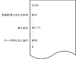
- FIG. 9 shows an example of a control program that performs a wait. In the control program of FIG.
- the control device is an adjustable interval (for example, processing) in a command for controlling at least one control target among a plurality of control targets when waste time occurs in a system in which a plurality of control targets operate in parallel.
- the wasted time is shortened by adjusting the speed and acceleration of the air cut section where the axis is moving without doing so, or the machining section where there is no big problem even if the machining conditions are adjusted). If the speed and acceleration of the adjustable section of the controlled object in which the waiting time occurs are adjusted in a direction of reducing the speed and acceleration, the power consumption of the controlled object and the impact generated in the machine can be reduced. Further, if the speed and acceleration of the adjustable section in the controlled object where the delay time occurs are adjusted in the direction of increasing, the cycle time of the entire system can be shortened. Regardless of which adjustment is made, the wasted time is reduced.
- An aspect of the present invention is an analysis unit that analyzes the control program in a control device that controls a plurality of different control targets based on at least one control program and performs parallel control to process the workpiece.
- the adjustable section detection unit that detects the adjustable section in the control program, and the plurality of control objects in the control program.
- At least one of the wasted time detection unit that detects the wasted time generated in the execution of the command related to the meeting in the control program and the speed and acceleration of the command related to the movement of the axis included in the controlled object in the adjustable section in the control program. It is a control device provided with a speed adjusting unit for adjusting the waste time so as to reduce the wasted time.
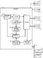
- FIG. 1 is a schematic hardware configuration diagram showing a main part of a control device according to the first embodiment of the present invention.
- the control device 1 of the present invention can be implemented as a control device that controls, for example, the control targets 3a and 3b based on a control program prepared for each control target.
- the function of the control device 1 according to the present embodiment can also be applied to the case where a plurality of control targets 3a and 3b are controlled in parallel by a single control program.
- the CPU 11 included in the control device 1 is a processor that controls the control device 1 as a whole.
- the CPU 11 reads the system program stored in the ROM 12 via the bus 22, and controls the entire control device 1 according to the system program. Temporary calculation data, display data, various data input from the outside, and the like are temporarily stored in the RAM 13.
- the non-volatile memory 14 is composed of, for example, a memory backed up by a battery (not shown), an SSD (Solid State Drive), or the like, and the storage state is maintained even when the power of the control device 1 is turned off.
- the non-volatile memory 14 contains control programs and data read from the external device 72 via the interface 15, control programs and data input from the input device 71 via the interface 18, and a fog computer via the network 5. Control programs, data, and the like acquired from other devices such as 6 and the cloud server 7 are stored.
- the data stored in the non-volatile memory 14 is, for example, the position, speed, acceleration, load of each motor in the controlled objects 3a and 3b, and each physical quantity detected by a sensor (not shown) attached to the other controlled objects 3a and 3b. Such data and the like may be included.
- the control program or data stored in the non-volatile memory 14 may be expanded in the RAM 13 at the time of execution / use. Further, various system programs such as a known analysis program are written in the ROM 12 in advance.
- the interface 15 is an interface for connecting the CPU 11 of the control device 1 to an external device 72 such as an external storage medium. From the external device 72 side, for example, a control program, setting data, and the like used for controlling the controlled objects 3a and 3b are read. Further, the control program, setting data, and the like edited in the control device 1 can be stored in an external storage medium such as a CF card or a USB memory (not shown) via the external device 72.
- the PLC (programmable logic controller) 16 executes a ladder program to execute a ladder program to control targets 3a and 3b and peripheral devices (for example, a tool changer, an actuator such as a robot, and control targets 3a and 3b).
- a signal is output and controlled via the I / O unit 19 to a sensor (sensor such as a temperature sensor or a humidity sensor) attached to the robot.
- a sensor sensor such as a temperature sensor or a humidity sensor
- it receives signals from various switches and peripheral devices on the operation panel installed in the main bodies of the controlled objects 3a and 3b, processes the signals necessary for the signals, and then passes them to the CPU 11.
- the interface 20 is an interface for connecting the CPU of the control device 1 and the wired or wireless network 5.
- the network 5 communicates using technologies such as serial communication such as RS-485, Ethernet (registered trademark) communication, optical communication, wireless LAN, Wi-Fi (registered trademark), and Bluetooth (registered trademark). It may be there.
- Higher-level management devices such as other machines, fog computers 6, and cloud servers 7 are connected to the network 5, and data is exchanged with and from the control device 1.
- each data read on the memory, data obtained as a result of executing the program, etc. are output via the interface 17 and displayed on the screen.
- the input device 71 composed of a keyboard, a pointing device, and the like passes commands, data, and the like based on operations by the operator to the CPU 11 via the interface 18.
- the axis control circuits 30a and 30b for controlling the axes included in the controlled objects 3a and 3b receive the axis movement command amount from the CPU 11 and output the axis command to the servo amplifiers 40a and 40b, respectively.
- the servo amplifiers 40a and 40b drive the servomotors 50a and 50b that move the drive unit included in the controlled objects 3a and 3b along the axis, respectively.
- the shaft servomotors 50a and 50b have a built-in position / speed detector, and the position / speed feedback signals from the position / speed detector are fed back to the shaft control circuits 30a and 30b, respectively, to perform position / speed feedback control. ..
- FIG. In the hardware configuration diagram of FIG.
- FIG. 2 shows a schematic block diagram of the functions provided by the control device 1 according to the first embodiment of the present invention.
- Each function included in the control device 1 according to the present embodiment is realized by the CPU 11 included in the control device 1 shown in FIG. 1 executing a system program and controlling the operation of each part of the control device 1.
- the control device 1 of the present embodiment includes an analysis unit 100, a control unit 110, an adjustable section detection unit 120, a wasted time detection unit 130, and a speed adjustment unit 140. Further, the RAM 13 to the non-volatile memory 14 of the control device 1 store control programs 200a and 200b for controlling the control targets 3a and 3b, respectively, and the adjustable sections of the control programs 200a and 200b are stored. An adjustable section storage unit 210, which is an area for storing, and a command position where wasted time occurs in the control programs 200a and 200b, and a wasted time storage unit 220, which is an area for storing the time, are provided, respectively. ing.
- the analysis unit 100 is realized by executing a system program read from the ROM 12 by the CPU 11 included in the control device 1 shown in FIG. 1 and performing arithmetic processing mainly by the CPU 11 using the RAM 13 and the non-volatile memory 14. ..
- the analysis unit 100 analyzes the control programs 200a and 200b and creates command data for controlling the control targets 3a and 3b provided with the servomotors 50a and 50b.
- the control programs 200a and 200b include commands generally used for controlling the controlled objects 3a and 3b. Commonly used commands include waiting commands and the like.
- the analysis unit 100 outputs the command data created based on the commands by the control programs 200a and 200b to the control unit 110.
- the control unit 110 executes a system program read from the ROM 12 by the CPU 11 included in the control device 1 shown in FIG. 1, mainly performs arithmetic processing using the RAM 13 and the non-volatile memory 14 by the CPU 11, and axis control circuits 30a and 30b. , The control process of each part of the control target 3a and 3b using the PLC 16 and the input / output process via the interface 18 are performed.
- the control unit 110 controls each unit of the control target 3a, 3b and the peripheral device based on the command data input from the analysis unit 100.
- the control unit 110 generates data related to the movement of the axes based on a command for moving the drive unit along the axes of the controlled objects 3a and 3b, and outputs the data to the servomotors 50a and 50b. Further, the control unit 110 generates, for example, a predetermined signal for operating the peripheral device based on a command for operating the peripheral device of the controlled object 3a, 3b, and outputs the signal to the PLC 16. On the other hand, the control unit 110 acquires the states of the servomotors 50a and 50b (motor current value, position, speed, acceleration, load, etc.) as feedback values and uses them for each control process.
- the states of the servomotors 50a and 50b (motor current value, position, speed, acceleration, load, etc.) as feedback values and uses them for each control process.
- the adjustable section detection unit 120 executes a system program read from the ROM 12 by the CPU 11 included in the control device 1 shown in FIG. 1, and performs arithmetic processing mainly by the CPU 11 using the RAM 13 and the non-volatile memory 14. It will be realized.
- the adjustable section detection unit 120 detects an adjustment section in which the speed and acceleration can be adjusted in the section in which the feed control of the axes of the control targets 3a and 3b is performed by the control programs 200a and 200b. ..
- the adjustable section detection unit 120 detects a section in which the air cut is performed in the control targets 3a and 3b as an adjustable section based on, for example, the control status by the control unit 110 and the feedback value fed back from the control targets 3a and 3b. do.
- the adjustable section detection unit 120 stores the detected adjustment section in the adjustable section storage unit 210 in association with the commands of the control programs 200a and 200b.
- the adjustable section detection unit 120 may detect, for example, a section in which fast forward is instructed as an adjustable section. Further, the adjustable section detection unit 120 sets a section in which, for example, a cutting feed is instructed and the feedback value of the load from the servomotors 50a and 50b for driving the shaft is smaller than a predetermined threshold value. It may be detected as an adjustable section.
- the adjustable section detection unit 120 may detect as an adjustable section a cutting section in which a machining condition does not cause a big problem in the section where the work is machined.
- the adjustable section detection unit 120 may detect, for example, a section in which a cutting feed is instructed and a cutting section for machining a long range as an adjustable section.
- the adjustable section detection unit 120 can adjust the section of the cutting feed that has been machined earlier, for example, in the section where the cutting feed is instructed and the same portion is machined in the previous machining. It may be detected as an interval.
- the wasted time detection unit 130 is realized by executing a system program read from the ROM 12 by the CPU 11 included in the control device 1 shown in FIG. 1 and performing arithmetic processing mainly by the CPU 11 using the RAM 13 and the non-volatile memory 14. Will be done.
- the wasted time detection unit 130 detects the wasted time generated in the controlled objects 3a and 3b based on the control status by the control unit 110, associates it with the command of the control programs 200a and 200b, and stores it in the wasted time storage unit 220. ..
- the wasted time stored in the wasted time storage unit 220 may include at least the time (waiting time) elapsed from the execution of the wait command in the control program to be controlled until the wait command is released. Further, the wasted time stored in the wasted time storage unit 220 may include the time (delay time) elapsed from the execution of the wait command in the control program to be controlled until the wait identifier is notified. good.
- the speed adjusting unit 140 is realized by executing a system program read from the ROM 12 by the CPU 11 included in the control device 1 shown in FIG. 1 and performing arithmetic processing mainly by the CPU 11 using the RAM 13 and the non-volatile memory 14. To.
- the speed adjusting unit 140 refers to the adjustable section stored in the adjustable section storage unit 210 and the wasted time stored in the wasted time storage unit 220, and the control program 200a is used to reduce the wasted time.
- 200b Adjust at least one of the command speeds and accelerations for the adjustable interval.
- the speed adjusting unit 140 may preferentially adjust the air cut section in each adjustable section.
- the speed adjusting unit 140 may adjust the cutting section when making adjustments for shortening the waiting time within the wasted time.
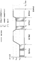
- FIG. 3 is a graph illustrating the relationship between the speed and time of the axial feed in the controlled object 3a.
- the horizontal shaded section indicates a cutting feed section in which the cutting load is equal to or higher than a predetermined threshold value
- the diagonal line shaded section indicates a cutting feed section in which the cutting load is equal to or lower than a predetermined threshold value
- the white section indicates a fast feed section. ..
- the cutting feed section in which the cutting load is equal to or less than a predetermined threshold value and the fast-forward section can be considered as adjustable sections.
- FIG. 3 is a graph illustrating the relationship between the speed and time of the axial feed in the controlled object 3a.
- the horizontal shaded section indicates a cutting feed section in which the cutting load is equal to or higher than a predetermined threshold value
- the diagonal line shaded section indicates a cutting feed section in which the cutting load is equal to or lower than a predetermined threshold value
- the white section indicates a fast feed section. ..
- the cutting feed command Na1 is executed at times t 0 to t 2
- the cutting feed command Na 3 is executed at times t 3 to t 6
- the fast forward command Na 2 and time t 6 to are executed at times t 2 to t 3 .
- the fast-forward command Na 4 is executed.
- the wait command Na5 is executed at time t7
- the control target 3a enters the wait state
- the control program 200b of the control target 3b commands the notification of the wait identifier at time t8 to cancel the wait state. And.
- the time (t 8 -t 7 ) is the wasted time (waiting time) in the command Na 5. ) Is stored in the wasted time storage unit 220.
- the speed adjusting unit 140 may, for example, cut feed speed v ac1 or acceleration at times t 1 to t 2 and time t 2 to so that the trigger for executing the command Na 5 coincides with approximately time t 8 . Adjust the fast-forward speed v ar and acceleration at t 3 , t 6 to t 7 , and the cutting feed speed v ac 2 and acceleration at times t 3 to t 4 , t 5 to t 6 to be small.
- FIG. 4 is a graph illustrating the relationship between the speed and time of the axial feed in the controlled object 3a after adjusting the speed in the adjustable section.
- FIG. 4 shows the speed and acceleration of the adjustable section adjusted so that the time t 7'when the movement by the fast-forward command Na 4 is completed coincides with the time t 8 .
- This speed adjustment can be realized, for example, by instructing the control unit 110 to set the override small in the adjustable section.
- the transition of the position of the axis when the override is adjusted may be calculated so that the time t 7'when the fast-forward command Na4 ends becomes the time t 8 .
- the integrated value (movement amount) of the speed when each command is executed is at least one of the speed and the acceleration so as to match the integrated value of the speed when each command is executed in FIG. Is adjusted.
- FIG. Is adjusted In FIG.
- the speeds and accelerations of all the adjustable sections are adjusted, but only the speeds and accelerations of some adjustable sections may be adjusted.
- the time t 7'when the movement by the fast-forward command Na 4 is completed is set to the time t 8 . Matching them has a great effect on reducing power consumption and impact on the machine.
- FIG. 5 is a graph illustrating the relationship between the speed and time of the axial feed in the controlled object 3b.
- the horizontal shaded section indicates a cutting feed section in which the cutting load is equal to or higher than a predetermined threshold value
- the diagonal line shaded section indicates a cutting feed section in which the cutting load is equal to or lower than a predetermined threshold value
- the white section indicates a fast feed section. ..
- the cutting feed command Nb1 is executed at times t 0 to t 2
- the cutting feed command Nb3 is executed at times t 3 to t 6
- the fast forward command Nb 2 and time t 6 to are executed at times t 2 to t 3 .
- the fast-forward command Nb4 is executed.
- the wait command Na5 is executed by the control program 200a of the control target 3a to enter the wait state of the control target 3b
- the wait identifier notification command Nb5 is issued by the control program 200b of the control target 3b. It is assumed that the execution is performed and the waiting state of the controlled object 3a is released.
- the delay time is from the time t 7 when the wait command Na 5 is executed by the control program 200a of the control target 3a to the time t 8 when the wait identifier notification command Nb 5 is executed by the control program 200b of the control target 3b. Therefore, the time (t 8 -t 7 ) is stored in the wasted time storage unit 220 as the wasted time (delayed time) in the command Nb5.
- the speed adjusting unit 140 may, for example, cut feed speed v bc1 at time t 1 to t 2 or acceleration, time t 2 ⁇ so that the trigger for executing the command Nb 5 coincides with approximately time t 7 .
- the fast-forward speed v br and acceleration at t 3 , t 6 to t 7 , and the cutting feed speed v bc2 and acceleration at times t 3 to t 4 , t 5 to t 6 are greatly adjusted.
- FIG. 6 is a graph illustrating the relationship between the speed and time of the axial feed in the controlled object 3b after adjusting the speed in the adjustable section.
- FIG. 6 shows the speed and acceleration of the adjustable section adjusted so that the time t 8'when the movement by the fast-forward command Nb4 ends coincides with the time t 7 .
- This speed adjustment can be realized, for example, by instructing the control unit 110 to set a large override in the adjustable section. The transition of the position of the axis when the override is adjusted may be calculated so that the time t 8'when the fast-forward command Nb4 ends becomes the time t 7 .
- the integrated value (movement amount) of the speed when each command is executed is at least one of the speed and the acceleration so as to match the integrated value of the speed when each command is executed in FIG. Is adjusted.
- the speeds and accelerations of all the adjustable sections are adjusted, but only the speeds and accelerations of some adjustable sections may be adjusted.
- the speed adjustment unit 140 describes each of the reduction of the waiting time and the reduction of the delay time, but the speed adjustment unit 140 reduces the waiting time of one controlled object and the delay time of another controlled object. May be done in combination.
- priority is given to shortening the waiting time and shortening the delay time, and the waste time of the higher priority is shortened first, and the portion that cannot be adjusted by that is lower in priority. You can make up for it by shortening the wasted time. For example, prioritize the reduction of waiting time, and reduce the speed or acceleration by 10% or more from the commanded speed, which must not be reduced below a predetermined threshold (for example, the speed or acceleration must not be reduced below a predetermined threshold).
- the waiting time cannot be reduced to 0 by shortening the waiting time, adjustments may be made to shorten the delay time of other control targets.
- priority is given to shortening the delay time, and the delay time is shortened under a predetermined limit (for example, the speed limit or acceleration of the shaft according to the mechanical specifications must not be larger). Therefore, if the delay time cannot be reduced to 0, adjustments may be made to shorten the waiting time of other controlled objects.
- the speed adjusting unit 140 When the adjustable section is not stored in the adjustable section storage unit 210 or the wasted time is not stored in the wasted time storage unit 220, the speed adjusting unit 140 has the speed and the speed in the control programs 200a and 200b. At least one of the acceleration cannot be adjusted.
- the adjustable section detection unit 120 detects the adjustable section and the waste time detection unit 130 detects the waste time while the control unit 110 controls the controlled objects 3a and 3b. Therefore, the speed adjusting unit 140 does not function in the processing of the first work in the present embodiment. However, the machining of the workpiece by the machine is repeated by automatic operation. Therefore, it should be noted that the speed adjustment by the speed adjusting unit 140 functions favorably in the second and subsequent machining by utilizing the adjustable section and the wasted time detected in the first machining.
- the wasted time generated in the system for controlling a plurality of controlled objects in parallel is effectively utilized by reducing the power consumption and the impact generated in the machine and shortening the cycle time.
- the power consumption It is possible to increase the cycle time without increasing the amount and the impact generated on the machine more than necessary.
- the control device 1 according to the second embodiment of the present invention includes an analysis unit 100, a control unit 110, an adjustable section detection unit 120, a wasted time detection unit 130, and a speed adjustment unit 140.
- the RAM 13 to the non-volatile memory 14 of the control device 1 store control programs 200a and 200b for controlling the control targets 3a and 3b, respectively, and the adjustable sections of the control programs 200a and 200b are stored.
- the adjustable section storage unit 210 which is an area for storage, the command position where the wasted time occurs in the control programs 200a, 200b, and the wasted time storage unit 220, which is an area for storing the time, are provided, respectively. There is.
- the analysis unit 100 has a function of pre-reading and analyzing the control programs 200a and 200b. Further, the analysis unit 100 has a function of predicting the time required to execute each command of the control programs 200a and 200b. For predicting the execution time of the command, for example, known techniques disclosed in Japanese Patent No. 4980458, Japanese Patent Application Laid-Open No. 2017-146859, and the like may be used. As for peripheral devices, the system that manages the entire line where the controlled objects 3a and 3b are located and the standby state of the peripheral devices are detected based on the signal acquired via the PLC 16 so that they can be used next time. The time may be estimated from the received or previous execution time.
- the adjustable section detection unit 120 can detect and adjust the section in which the fast-forward command is executed among the commands included in the control programs 200a and 200b as the adjustable section in at least the first machining. It is stored in the section storage unit 210. Further, the adjustable section detection unit 120 detects a machining section in which a major problem does not occur even if the machining conditions are adjusted among the commands included in the control programs 200a and 200b as the adjustable section, and stores the adjustable section. It may be stored in the unit 210. Further, the wasted time detecting unit 130 according to the present embodiment calculates the wasted time (waiting time and delay time) generated in the waiting included in the control programs 200a and 200b based on the prediction result of the processing time by the analysis unit. , The calculated wasted time is stored in the wasted time storage unit 220. The functions provided in the other configurations are the same as those in the first embodiment.
- the control device 1 can pre-read the control programs 200a and 200b and detect the adjustable section and the wasted time in advance. Therefore, the wasted time can be shortened from the first processing. If the look-ahead by the analysis unit 100 is not sufficient, the normal processing is proceeded, but if the look-ahead is sufficient, the section that can be used within the look-ahead range can be grasped in advance, so that the speed and acceleration are within that range. At least one of the adjustments can be made. In order to further improve the accuracy, the above-mentioned machining time prediction function is used only in the first machining, and in parallel with this, accurate adjustable sections and wasted time are detected in the first machining, and the second machining. From machining, at least one of the adjustable intervals detected in the actual machining and the speed and acceleration based on the wasted time may be adjusted.
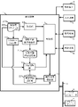
- FIG. 8 shows a schematic block diagram of the functions included in the control device 1 according to the third embodiment of the present invention.
- Each function included in the control device 1 according to the present embodiment is realized by the CPU 11 included in the control device 1 shown in FIG. 1 executing a system program and controlling the operation of each part of the control device 1.
- the control device 1 Similar to the control device 1 according to the first embodiment, the control device 1 according to the present embodiment includes an analysis unit 100, a control unit 110, an adjustable section detection unit 120, a wasted time detection unit 130, and a speed adjustment unit 140, and further.
- a simulation unit 150 is provided.
- the RAM 13 to the non-volatile memory 14 of the control device 1 store control programs 200a and 200b for controlling the control targets 3a and 3b, respectively, and the adjustable sections of the control programs 200a and 200b are stored.
- the adjustable section storage unit 210 which is an area for storage, the command position where the wasted time occurs in the control programs 200a, 200b, and the wasted time storage unit 220, which is an area for storing the time, are provided, respectively. There is.
- the functions of the analysis unit 100, the control unit 110, and the speed adjustment unit 140 according to the present embodiment are the same as the functions according to the first embodiment.
- the simulation unit 150 is realized by executing a system program read from the ROM 12 by the CPU 11 included in the control device 1 shown in FIG. 1 and performing arithmetic processing mainly by the CPU 11 using the RAM 13 and the non-volatile memory 14. ..
- the simulation unit 150 performs a known simulation process based on the control programs 200a and 200b.
- a known method disclosed in JP-A-2003-291333, JP-A-09-07330, and the like can be used.
- the adjustable section detection unit 120 is a section in which a fast-forward section is commanded and a section in which a cutting feed is commanded based on the result of simulation processing by the simulation unit 150, and the work and the tool are connected to each other.
- the non-contact air cut section is detected as an adjustable section and stored in the adjustable section storage unit 210.
- the adjustable section detection unit 120 detects a processing section as an adjustable section, which does not cause a big problem even if the processing conditions are adjusted, based on the result of the simulation processing by the simulation unit 150, and the adjustable section storage unit 210. You may memorize it in.
- the wasted time detecting unit 130 calculates the wasted time (waiting time and delay time) generated in the waiting included in the control programs 200a and 200b based on the result of the simulation processing by the simulation unit 150. , The calculated wasted time is stored in the wasted time storage unit 220.
- the functions provided in the other configurations are the same as those in the first embodiment.
- the control device 1 can detect the adjustable section and the wasted time in advance by the simulation process based on the control programs 200a and 200b. Therefore, the wasted time can be shortened from the first processing.
- the above-mentioned machining time prediction function is used only in the first machining, and in parallel with this, accurate adjustable sections and wasted time are detected in the first machining, and the second machining. From machining, at least one of the adjustable intervals detected in the actual machining and the speed and acceleration based on the wasted time may be adjusted.
- the speed adjusting unit 140 automatically determines an adjustable section for adjusting at least one of the speed and the acceleration.
- the adjustable section for speed adjustment may be selected at the operator's discretion. In this case, for example, when the first machining is completed, a graph as illustrated in FIGS. 3 and 5 is displayed on the display device 70 of the control device 1. Then, the operator is made to select the adjustable section to be adjusted.
- each control program is divided into a wait command and a command for notifying the wait identifier in advance to form a segment. Then, when adjusting at least one of the speed and the acceleration in order to reduce the wasted time related to a certain wait command and a command for notifying the wait identifier, the segment immediately before the wait command and the command for notifying the wait identifier. At least one of the velocity and the acceleration may be adjusted for the adjustable section within the range of.
Landscapes
- Engineering & Computer Science (AREA)
- Human Computer Interaction (AREA)
- Manufacturing & Machinery (AREA)
- Physics & Mathematics (AREA)
- General Physics & Mathematics (AREA)
- Automation & Control Theory (AREA)
- Numerical Control (AREA)
Abstract
Description
複数の加工系統やローダ系統を備えた多系統システムを制御する多系統制御を行う場合、それぞれの系統間の動作を協調動作させるために待ち合わせ制御を行う場合がある(例えば、特許文献1等)。それぞれの系統を制御するための指令は、一般にそれぞれの系統毎に異なる制御用プログラムに含まれる。待ち合わせ制御を行うために、それぞれの制御用プログラムの指令には、他の系統や周辺機器と「待ち」を行う指令が存在する。各系統の制御用プログラムや周辺機器は、お互いに待つことで協調して動作する。図9は、待ち合わせを行う制御用プログラムの例を示している。図9の制御用プログラムでは、M101指令により系統間待ち合わせを行うことを指令し、WAIT(3)指令で他の系統から待ち合わせ識別子3が通知されるまで制御用プログラムの動作を一時停止する。そして、相手の系統が所定の状態になって待ち合わせ識別子3を通知してくると、制御用プログラムの実行を再開してM200指令でローダを呼び出す。この制御用プログラムを用いることで、他の系統で待ち合わせ識別子3を通知する指令が実行されるまでローダ呼び出し指令の実行を待たせることができる。
単一系統内において、制御用プログラムから周辺装置を呼び出して利用する場合、該周辺装置を呼び出す指令を実行したあと、そのまま制御用プログラムの実行が継続される。この時、継続して実行されるブロックの中に、周辺装置の動作状態が所定の状態(周辺装置の駆動部が所定の位置まで移動した状態など)になるまで実行できないブロックがあった場合、当該ブロックにおいて、周辺装置が所定の状態になった時に通知される信号を待つ待ち指令が実行される。そして、周辺装置が所定の状態になり、信号が通知されると、待ち指令は解除されて制御用プログラムの実行が継続される。このような待ち合わせ処理は、同一ブロック内の指令間で行われることもある。
このような、複数の制御対象が並列動作するシステムにおいて発生する無駄時間を有効に活用する技術的手法が望まれている。
図1は本発明の第1実施形態による制御装置の要部を示す概略的なハードウェア構成図である。
本実施形態では、本発明の制御装置が備える機能を複数の制御対象を複数の制御用プログラムにより並列制御した場合を例として説明する。本発明の制御装置1は、例えば制御対象3a,3bを制御対象毎に用意された制御用プログラムに基づいて制御する制御装置として実装することができる。なお、本実施形態による制御装置1の機能は、単一の制御用プログラムにより複数の制御対象3a,3bを並列制御する場合にも適用できる。
図3は、制御対象3aにおける軸送りの速度と時間との関係を例示するグラフである。図3において、横線網掛けの区間は切削負荷が所定の閾値以上の切削送り区間、斜線網掛け区間は切削負荷が所定の閾値以下の切削送り区間、白抜きの区間は早送り区間を示している。このうち、切削負荷が所定の閾値以下の切削送り区間、及び早送り区間は調整可能区間と考えることができる。図3の例では、時刻t0~t2では切削送り指令Na1、時刻t3~t6では切削送り指令Na3が実行されており、時刻t2~t3では早送り指令Na2、時刻t6~t7では早送り指令Na4が実行されているとする。また、時刻t7に待ち指令Na5が実行されて制御対象3aは待ち状態に入り、時刻t8に制御対象3bの制御用プログラム200bで待ち合わせ識別子の通知が指令されて待ち状態が解除されたものとする。
図4は、調整可能区間における速度を調整した後の制御対象3aにおける軸送りの速度と時間との関係を例示するグラフである。
図4は、早送り指令Na4による移動が終了した時刻t7’が時刻t8と一致するように調整可能区間の速度と加速度を調整したものである。この速度調整は、例えば調整可能の区間においてオーバライドを小さく設定するように制御部110に指令することで実現できる。オーバライドを調整した場合の軸の位置の推移を計算して、早送り指令Na4が終了する時刻t7’が時刻t8となるようにすればよい。この時、各指令が実行されている際の速度の積分値(移動量)は、図3における各指令が実行されている際の速度の積分値と一致するように速度及び加速度の少なくともいずれかの調整が行われる。なお、図4では、全ての調整可能区間の速度や加速度を調整しているが、一部の調整可能区間の速度及び加速度のみを調整するようにしてもよい。このような場合には、例えば図3において速度が大きく変化している早送り指令N2の速度や加速度を調整することでするは、早送り指令Na4による移動が終了した時刻t7’が時刻t8と一致するようにすると、消費電力や機械に対する衝撃の低減に大きな効果が生じる。
図5は、制御対象3bにおける軸送りの速度と時間との関係を例示するグラフである。図5において、横線網掛けの区間は切削負荷が所定の閾値以上の切削送り区間、斜線網掛け区間は切削負荷が所定の閾値以下の切削送り区間、白抜きの区間は早送り区間を示している。図5の例では、時刻t0~t2では切削送り指令Nb1、時刻t3~t6では切削送り指令Nb3が実行されており、時刻t2~t3では早送り指令Nb2、時刻t6~t7では早送り指令Nb4が実行されているとする。また、時刻t7に制御対象3aの制御用プログラム200aで待ち指令Na5を実行されて制御対象3bの待ち状態に入り、時刻t8に制御対象3bの制御用プログラム200bで待ち合わせ識別子通知指令Nb5が実行されて制御対象3aの待ち状態が解除されたものとする。
図6は、調整可能区間における速度を調整した後の制御対象3bにおける軸送りの速度と時間との関係を例示するグラフである。図6は、早送り指令Nb4による移動が終了した時刻t8’が時刻t7と一致するように調整可能区間の速度と加速度を調整したものである。この速度調整は、例えば調整可能区間においてオーバライドを大きく設定するように制御部110に指令することにより実現できる。オーバライドを調整した場合の軸の位置の推移を計算して、早送り指令Nb4が終了する時刻t8’が時刻t7となるようにすればよい。この時、各指令が実行されている際の速度の積分値(移動量)は、図5における各指令が実行されている際の速度の積分値と一致するように速度及び加速度の少なくともいずれかの調整が行われる。なお、図6では、全ての調整可能区間の速度や加速度を調整しているが、一部の調整可能区間の速度及び加速度のみを調整するようにしてもよい。
本実施形態による制御装置1は、第1実施形態による制御装置1と同様に、解析部100、制御部110、調整可能区間検出部120、無駄時間検出部130、速度調整部140を備える。また、制御装置1のRAM13乃至不揮発性メモリ14には、制御対象3a,3bをそれぞれ制御するための制御用プログラム200a,200bが記憶されると共に、該制御用プログラム200a,200bの調整可能区間を記憶するための領域である調整可能区間記憶部210、該制御用プログラム200a,200bにおける無駄時間が発生する指令位置とその時間を記憶するための領域である無駄時間記憶部220がそれぞれ設けられている。
その他の構成が備える機能については、第1実施形態と同様である。
更に精度を上げるために、上記した加工時間の予測の機能は最初の加工においてのみ活用し、これと並列して1回目の加工で正確な調整可能区間及び無駄時間の検出を行い、2回目の加工からは実際の加工で検出された調整可能区間及び無駄時間に基づく速度及び加速度の少なくともいずれかの調整を行うようにしてもよい。
シミュレーション部150は、図1に示した制御装置1が備えるCPU11がROM12から読み出したシステム・プログラムを実行し、主としてCPU11によるRAM13、不揮発性メモリ14を用いた演算処理が行われることで実現される。シミュレーション部150は、制御用プログラム200a,200bに基づく公知のシミュレーション処理を行う。シミュレーションの処理には、例えば特開2003-291033号公報や特開平09-073309等に開示される公知の方法を用いることができる。
また、本実施形態による無駄時間検出部130は、シミュレーション部150によるシミュレーション処理の結果に基づいて、制御用プログラム200a,200bに含まれる待ち合わせにおいて発生する無駄時間(待ち時間及び遅れ時間)を算出し、算出した無駄時間を無駄時間記憶部220に記憶する。
その他の構成が備える機能については、第1実施形態と同様である。
例えば、上記した実施形態では、速度及び加速度の少なくともいずれかの調整を行う調整可能区間を速度調整部140で自動的に決定している。しかしながら、速度調整を行う調整可能区間をオペレータの判断により選択できるようにしてもよい。この場合、例えば1回目の加工が終了した時点で、図3,図5等に例示されるようなグラフを制御装置1の表示装置70に表示する。そして、調整対処とする調整可能区間をオペレータに選択させる。複数の制御対象を並列制御するシステムでは、ある制御対象の軸の送り速度を上げることにより、加工中の他の制御対象の加工面に悪影響が生じる場合もある。このような区間が速度調整の対象となると、複数の制御対象間で機械的干渉(衝突など)が起きることがある。オペレータに速度調整対象となる調整可能区間を選択させることで、このような事態を回避することができる。
3a,3b 制御対象
5 ネットワーク
6 フォグコンピュータ
7 クラウドサーバ
11 CPU
12 ROM
13 RAM
14 不揮発性メモリ
15,17,18,20 インタフェース
16 PLC
19 I/Oユニット
22 バス
30a,30b 軸制御回路
40a,40b サーボアンプ
50a,50b サーボモータ
70 表示装置
71 入力装置
72 外部機器
100 解析部
110 制御部
120 調整可能区間検出部
130 無駄時間検出部
140 速度調整部
150 シミュレーション部
200a,200b 制御用プログラム
210 調整可能区間記憶部
220 無駄時間記憶部
Claims (6)
- 制御用プログラムに基づいて複数の異なる制御対象を制御してワークを加工する並列制御を行う制御装置において、
前記制御用プログラムを解析する解析部と、
前記解析部による解析結果に基づいて複数の前記制御対象を制御する制御部と、
前記制御用プログラムにおける調整可能区間を検出する調整可能区間検出部と、
前記制御用プログラムにおける複数の前記制御対象間での待ち合わせに係る指令の実行において発生する無駄時間を検出する無駄時間検出部と、
前記制御用プログラムの前記調整可能区間における前記制御対象が備える軸の移動に係る指令の速度及び加速度の少なくともいずれかを、前記無駄時間が短縮するように調整する速度調整部と、
を備えた制御装置。 - 前記無駄時間は、複数の前記制御対象の内の第1制御対象が待ち状態となってから、前記第1制御対象とは異なる第2制御対象が前記待ち状態が解除される所定の状態になるまでの時間である、前記第1制御対象の待ち時間であり、
前記速度調整部は、前記待ち状態になる以前に実行される調整可能区間における前記第1制御対象の前記軸の移動に係る指令の速度及び加速度の少なくともいずれかを小さくすることで、前記待ち時間を短縮する、
請求項1に記載の制御装置。 - 前記無駄時間は、複数の前記制御対象の内の第1制御対象が待ち状態となってから、前記第1制御対象とは異なる第2制御対象が前記待ち状態が解除される所定の状態になるまでの時間である、前記第2制御対象の遅れ時間であり、
前記速度調整部は、前記待ち状態になる以前に実行される調整可能区間における前記第2制御対象の前記軸の移動に係る指令の速度及び加速度の少なくともいずれかを大きくすることで、前記遅れ時間を短縮する、
請求項1に記載の制御装置。 - 前記調整可能区間検出部は、前記制御部による複数の前記制御対象の制御状況に基づいて前記調整可能区間を検出し、
前記無駄時間検出部は、前記制御部による複数の前記制御対象の制御状況に基づいて前記無駄時間を検出する、
請求項1に記載の制御装置。 - 前記解析部は、前記制御用プログラムに含まれる複数の指令を先読みして解析すると共に、複数の前記指令の実行時間を予測し、
前記調整可能区間検出部は、少なくとも1回目のワークの加工において、前記制御用プログラムに含まれる切削送り指令が実行されるにも関わらず負荷が検出されない区間を調整可能区間として検出し、
前記無駄時間検出部は、前記解析部による複数の前記指令の実行時間の予測結果に基づいて、前記無駄時間を検出する、
請求項1に記載の制御装置。 - 複数の前記制御用プログラムに基づいてシミュレーション処理を実行するシミュレーション部をさらに備え、
前記調整可能区間検出部は、少なくとも1回目のワークの加工において、前記シミュレーション処理の結果に基づいて調整可能区間を検出し、
前記無駄時間検出部は、前記シミュレーション処理の結果に基づいて前記無駄時間を検出する、
請求項1に記載の制御装置。
Priority Applications (5)
| Application Number | Priority Date | Filing Date | Title |
|---|---|---|---|
| CN202180074008.0A CN116438491A (zh) | 2020-11-05 | 2021-11-01 | 控制装置 |
| DE112021004581.4T DE112021004581T5 (de) | 2020-11-05 | 2021-11-01 | Steuervorrichtung |
| US18/032,236 US20230393560A1 (en) | 2020-11-05 | 2021-11-01 | Control device |
| JP2022560764A JP7568740B2 (ja) | 2020-11-05 | 2021-11-01 | 制御装置 |
| JP2024128623A JP2024153888A (ja) | 2020-11-05 | 2024-08-05 | 制御装置 |
Applications Claiming Priority (2)
| Application Number | Priority Date | Filing Date | Title |
|---|---|---|---|
| JP2020184877 | 2020-11-05 | ||
| JP2020-184877 | 2020-11-05 |
Publications (1)
| Publication Number | Publication Date |
|---|---|
| WO2022097607A1 true WO2022097607A1 (ja) | 2022-05-12 |
Family
ID=81457918
Family Applications (1)
| Application Number | Title | Priority Date | Filing Date |
|---|---|---|---|
| PCT/JP2021/040253 Ceased WO2022097607A1 (ja) | 2020-11-05 | 2021-11-01 | 制御装置 |
Country Status (5)
| Country | Link |
|---|---|
| US (1) | US20230393560A1 (ja) |
| JP (2) | JP7568740B2 (ja) |
| CN (1) | CN116438491A (ja) |
| DE (1) | DE112021004581T5 (ja) |
| WO (1) | WO2022097607A1 (ja) |
Citations (4)
| Publication number | Priority date | Publication date | Assignee | Title |
|---|---|---|---|---|
| JP2007122387A (ja) * | 2005-10-27 | 2007-05-17 | Star Micronics Co Ltd | 工作機械及び工作機械におけるプログラムデータ作成方法 |
| JP2007234002A (ja) * | 2006-02-06 | 2007-09-13 | Citizen Holdings Co Ltd | 数値制御工作機械、この数値制御工作機械におけるワークの加工方法 |
| JP2016062175A (ja) * | 2014-09-16 | 2016-04-25 | 中村留精密工業株式会社 | 工作機械の運転制御装置 |
| JP2018197989A (ja) * | 2017-05-24 | 2018-12-13 | ファナック株式会社 | 数値制御装置 |
Family Cites Families (12)
| Publication number | Priority date | Publication date | Assignee | Title |
|---|---|---|---|---|
| JP3259112B2 (ja) * | 1993-09-10 | 2002-02-25 | 株式会社山武 | コントローラ |
| JP3259115B2 (ja) * | 1993-12-06 | 2002-02-25 | 株式会社山武 | コントローラ |
| JP3148108B2 (ja) | 1995-09-01 | 2001-03-19 | 本田技研工業株式会社 | 5軸ncデータのチェック方法 |
| JP3946560B2 (ja) | 2002-04-02 | 2007-07-18 | 株式会社ソディック | 数値制御プログラム作成方法と数値制御放電加工装置 |
| JP2008046899A (ja) * | 2006-08-17 | 2008-02-28 | Mitsubishi Electric Corp | 数値制御装置 |
| JP2009257221A (ja) * | 2008-04-17 | 2009-11-05 | Denso Corp | 内燃機関の空燃比制御装置 |
| JP4980458B2 (ja) | 2010-10-27 | 2012-07-18 | ファナック株式会社 | 数値制御工作機械の加工時間予測装置 |
| JP6122048B2 (ja) | 2015-02-20 | 2017-04-26 | ファナック株式会社 | 待ち合わせ相手の制御系を判別する数値制御装置 |
| JP6603140B2 (ja) * | 2016-01-19 | 2019-11-06 | ファナック株式会社 | 数値制御装置 |
| JP6309986B2 (ja) * | 2016-02-18 | 2018-04-11 | ファナック株式会社 | 数値制御工作機械の加工時間予測装置 |
| JP6333915B2 (ja) * | 2016-10-20 | 2018-05-30 | ファナック株式会社 | 数値制御装置 |
| JP6950415B2 (ja) * | 2017-09-29 | 2021-10-13 | オムロン株式会社 | 制御装置 |
-
2021
- 2021-11-01 JP JP2022560764A patent/JP7568740B2/ja active Active
- 2021-11-01 WO PCT/JP2021/040253 patent/WO2022097607A1/ja not_active Ceased
- 2021-11-01 DE DE112021004581.4T patent/DE112021004581T5/de active Pending
- 2021-11-01 CN CN202180074008.0A patent/CN116438491A/zh active Pending
- 2021-11-01 US US18/032,236 patent/US20230393560A1/en active Pending
-
2024
- 2024-08-05 JP JP2024128623A patent/JP2024153888A/ja active Pending
Patent Citations (4)
| Publication number | Priority date | Publication date | Assignee | Title |
|---|---|---|---|---|
| JP2007122387A (ja) * | 2005-10-27 | 2007-05-17 | Star Micronics Co Ltd | 工作機械及び工作機械におけるプログラムデータ作成方法 |
| JP2007234002A (ja) * | 2006-02-06 | 2007-09-13 | Citizen Holdings Co Ltd | 数値制御工作機械、この数値制御工作機械におけるワークの加工方法 |
| JP2016062175A (ja) * | 2014-09-16 | 2016-04-25 | 中村留精密工業株式会社 | 工作機械の運転制御装置 |
| JP2018197989A (ja) * | 2017-05-24 | 2018-12-13 | ファナック株式会社 | 数値制御装置 |
Also Published As
| Publication number | Publication date |
|---|---|
| DE112021004581T5 (de) | 2023-06-15 |
| JP2024153888A (ja) | 2024-10-29 |
| JP7568740B2 (ja) | 2024-10-16 |
| JPWO2022097607A1 (ja) | 2022-05-12 |
| US20230393560A1 (en) | 2023-12-07 |
| CN116438491A (zh) | 2023-07-14 |
Similar Documents
| Publication | Publication Date | Title |
|---|---|---|
| US8140177B2 (en) | Numerical controller with interference check function | |
| US7764039B2 (en) | Numerical controller | |
| JP6209392B2 (ja) | 干渉確認装置 | |
| US10048675B2 (en) | Numerical controller performing 3-dimensional interference check corresponding to feedrate change | |
| JPH0384604A (ja) | 数値制御装置の送り速度制御方法 | |
| US10824136B2 (en) | Setting device and computer readable medium | |
| US11340587B2 (en) | Numerical controller | |
| US11402822B2 (en) | Numerical controller | |
| US20200133236A1 (en) | Numerical controller | |
| US11003161B2 (en) | Numerical controller | |
| JP2020003958A (ja) | 数値制御装置 | |
| WO2022097607A1 (ja) | 制御装置 | |
| US10401826B2 (en) | Numerical controller facilitating measure to be taken after detection of interference | |
| US11156986B2 (en) | Machining program editing device | |
| US11415964B2 (en) | Numerical control system with distributed look-ahead processing of multiple numerical controllers | |
| JP7568853B2 (ja) | 制御装置及び制御システム | |
| CN111316178B (zh) | 用于运行数控生产系统的方法及其生产系统 | |
| US12443168B2 (en) | Speed adjustment support device | |
| JP7832328B2 (ja) | 数値制御装置 | |
| JP7502135B2 (ja) | ロボットプログラム調整装置 | |
| JP2019212029A (ja) | 数値制御装置 | |
| JP2021044020A (ja) | 数値制御装置 | |
| JP7283875B2 (ja) | 数値制御装置 | |
| WO2026069931A1 (ja) | 制御方法、プログラム、及び制御システム | |
| JPH04100123A (ja) | 数値制御装置の加減速時定数設定方式 |
Legal Events
| Date | Code | Title | Description |
|---|---|---|---|
| 121 | Ep: the epo has been informed by wipo that ep was designated in this application |
Ref document number: 21889160 Country of ref document: EP Kind code of ref document: A1 |
|
| ENP | Entry into the national phase |
Ref document number: 2022560764 Country of ref document: JP Kind code of ref document: A |
|
| WWE | Wipo information: entry into national phase |
Ref document number: 18032236 Country of ref document: US |
|
| 122 | Ep: pct application non-entry in european phase |
Ref document number: 21889160 Country of ref document: EP Kind code of ref document: A1 |