WO2022097448A1 - 車載ecu、プログラム及びフェールセーフ方法 - Google Patents
車載ecu、プログラム及びフェールセーフ方法 Download PDFInfo
- Publication number
- WO2022097448A1 WO2022097448A1 PCT/JP2021/038162 JP2021038162W WO2022097448A1 WO 2022097448 A1 WO2022097448 A1 WO 2022097448A1 JP 2021038162 W JP2021038162 W JP 2021038162W WO 2022097448 A1 WO2022097448 A1 WO 2022097448A1
- Authority
- WO
- WIPO (PCT)
- Prior art keywords
- application
- vehicle
- negative
- fail
- ecu
- Prior art date
- Legal status (The legal status is an assumption and is not a legal conclusion. Google has not performed a legal analysis and makes no representation as to the accuracy of the status listed.)
- Ceased
Links
Images





Classifications
-
- B—PERFORMING OPERATIONS; TRANSPORTING
- B60—VEHICLES IN GENERAL
- B60R—VEHICLES, VEHICLE FITTINGS, OR VEHICLE PARTS, NOT OTHERWISE PROVIDED FOR
- B60R16/00—Electric or fluid circuits specially adapted for vehicles and not otherwise provided for; Arrangement of elements of electric or fluid circuits specially adapted for vehicles and not otherwise provided for
- B60R16/02—Electric or fluid circuits specially adapted for vehicles and not otherwise provided for; Arrangement of elements of electric or fluid circuits specially adapted for vehicles and not otherwise provided for electric constitutive elements
-
- G—PHYSICS
- G06—COMPUTING OR CALCULATING; COUNTING
- G06F—ELECTRIC DIGITAL DATA PROCESSING
- G06F21/00—Security arrangements for protecting computers, components thereof, programs or data against unauthorised activity
- G06F21/50—Monitoring users, programs or devices to maintain the integrity of platforms, e.g. of processors, firmware or operating systems
- G06F21/57—Certifying or maintaining trusted computer platforms, e.g. secure boots or power-downs, version controls, system software checks, secure updates or assessing vulnerabilities
-
- G—PHYSICS
- G06—COMPUTING OR CALCULATING; COUNTING
- G06F—ELECTRIC DIGITAL DATA PROCESSING
- G06F9/00—Arrangements for program control, e.g. control units
- G06F9/06—Arrangements for program control, e.g. control units using stored programs, i.e. using an internal store of processing equipment to receive or retain programs
- G06F9/44—Arrangements for executing specific programs
- G06F9/4401—Bootstrapping
Definitions
- the present disclosure relates to in-vehicle ECUs, programs and fail-safe methods.
- This application claims priority based on Japanese Application No. 2020-184519 filed on November 4, 2020, and incorporates all the contents described in the Japanese application.
- the vehicle is equipped with an ECU (Electronic Control Unit) for controlling in-vehicle devices such as power train systems such as engine control and body systems such as air conditioner control.
- the ECU includes an arithmetic processing unit such as an MPU, a rewritable non-volatile storage unit such as RAM, and a communication unit for communicating with other ECUs, and by reading and executing a control program stored in the storage unit. , Controls in-vehicle devices.
- a secure boot method is known that verifies the integrity of the control program at the time of starting the ECU and permits the booting of the ECU when the verification is successful (for example, Patent Document). See 1).
- Patent Document 1 performs fail-safe in verifying the integrity of a control program so that the problematic control program (software) is not started when the number of failures exceeds a specified value.
- the in-vehicle ECU is an in-vehicle ECU mounted on a vehicle, and is a control unit that executes a plurality of applications, and each of the plurality of applications when the control unit executes a plurality of applications.
- the control unit is provided with a verification unit for performing verification, and the control unit executes an application in which verification by the verification unit is positive, does not execute an application in which verification by the verification unit is negative, and substitutes for the negative application.
- the fail-safe process includes a process of identifying the negative application and outputting an alternative signal corresponding to the specified negative application.
- Patent Document 1 has a problem that the point of substituting an application that could not be started due to the verification result of secure boot is not taken into consideration.
- the purpose of the present disclosure is to provide an in-vehicle ECU or the like that can replace an application that could not be started.
- the in-vehicle ECU is an in-vehicle ECU mounted on a vehicle, and is a control unit that executes a plurality of applications, and the plurality of vehicle-mounted ECUs when the control unit executes a plurality of applications.
- the control unit is provided with a verification unit for verifying each application, and the control unit executes an application in which the verification by the verification unit is positive, and does not execute an application in which the verification by the verification unit is negative, and the negative.
- a fail-safe process that substitutes for an application is executed, and the fail-safe process includes a process of identifying the negative application and outputting a substitute signal corresponding to the specified negative application.
- the control unit of the in-vehicle ECU determines whether or not each of the plurality of applications can be executed (startup determination) based on the verification results of the verification unit for the plurality of applications. Will be a secure boot. Since the control unit does not execute the application that has a negative verification result by the verification unit that plays a part of the secure boot, the appropriateness (integrity) of the application executed in the in-vehicle ECU can be guaranteed. Further, the control unit of the in-vehicle ECU efficiently substitutes the application that could not be started due to the verification result of the secure boot by executing the fail-safe process including the process of outputting the substitute signal according to the negative application. It can be carried out.
- the fail-safe program for executing the fail-safe process is stored in a non-rewritable storage area.
- the fail-safe program for executing the fail-safe process is stored in the non-rewritable storage area in the storage unit provided in the vehicle-mounted ECU, for example, falsification to the fail-safe program from inside or outside the vehicle is performed. It is possible to improve the robustness against attacks such as.
- pattern information in which a combination of the applications and information related to the alternative signal are associated is stored in the non-rewritable storage area, and the control unit.
- the fail-safe process according to the above includes a process of outputting an alternative signal according to the specified negative application with reference to the pattern information.
- the control unit of the in-vehicle ECU executes a plurality of applications, and depending on the verification result of the verification unit, only a single application may have a negative verification result, or a plurality of applications are negative.
- the verification result may be different.
- the pattern information stored in the storage area of the vehicle-mounted ECU includes a combination of each application in the plurality of applications and information on an alternative signal associated with the combination.
- the combination of the applications is not limited to the combination of two or more applications, and includes a single application. Therefore, the control unit of the in-vehicle ECU can refer to the pattern information not only when the specified application is single but also when there are a plurality of specified applications, depending on the combination of the specified single or multiple applications. It is possible to efficiently acquire information on the alternative signal and output the alternative signal based on the information.
- the in-vehicle ECU includes a process of outputting an alternative signal to the executed positive application in the process of outputting the alternative signal by the control unit.
- the control unit of the in-vehicle ECU has a plurality of applications to be executed, for example, interprocess communication is performed between these applications to perform a cooperative operation or a dependent operation.
- the process of outputting the substitute signal by the control unit is not only the process of outputting the substitute signal to the in-vehicle ECU other than the own ECU, but also the application executed by the own ECU (control unit) (verification result). Includes processing to output an alternative signal even for positive applications). Therefore, in a plurality of applications to be executed in the own ECU (vehicle-mounted ECU), even if there is a dependency of operation processing between these applications, the control unit substitutes for the executed positive application. Output a signal. Therefore, it is possible to perform an overall or comprehensive fail-safe process for a plurality of applications in the in-vehicle ECU.
- the control unit generates a plurality of virtual environments by a virtualized operating system, and each of the plurality of applications is one of the plurality of virtual environments.
- the virtual environment is used as an operating environment
- the verification unit verifies each of the plurality of virtual environments
- the control unit generates a virtual environment in which the verification by the verification unit is positive, and the verification unit performs the verification.
- the virtual environment whose verification is negative is not generated, and the fail-safe process that substitutes the application whose operating environment is the negative virtual environment is executed.
- control unit of the in-vehicle ECU creates a plurality of virtual environments by the virtualized operating system, and each of the plurality of applications is executed on one of the virtual environments. That is, each of the plurality of applications does not operate in a physical hardware environment such as a CPU, but is executed using the virtual environment generated by the virtualized operating system as the operating environment.
- the verification unit verifies the virtual environment (guest OS), and the control unit verifies the virtual environment (guest OS), and the control unit is a positive virtual environment based on the verification results.
- the appropriateness (integrity) for each of these virtual environments (guest OS) can be guaranteed. Since a negative virtual environment is not generated, the application that uses the negative virtual environment as the operating environment will not be executed, whereas the control unit will execute the application that uses the negative virtual environment as the operating environment. Perform an alternative fail-safe process.
- the in-vehicle ECU includes the virtual environment and the virtual environment as an operating environment in a non-rewritable storage area in which a fail-safe program for executing the fail-safe process is stored.
- the operating environment information associated with one or more applications is stored, and the fail-safe process by the control unit refers to the operating environment information and sets the negative virtual environment as the operating environment. Includes processing to identify the application.
- the control unit of the in-vehicle ECU creates a plurality of virtual environments, and in each of the generated virtual environments, a single application or a plurality of applications are executed.
- the operating environment information associated with the environment and one or more applications whose operating environment is a virtual environment is stored. Therefore, the control unit of the in-vehicle ECU identifies an application whose operating environment is a virtual environment that was not generated due to a negative verification result by referring to the operating environment information, and by referring to, for example, pattern information. , It is possible to efficiently perform the process of outputting an alternative signal according to the specified application.
- the program according to one aspect of the present disclosure verifies each of the plurality of applications on a computer mounted on a vehicle and executing a plurality of applications, and executes an application whose verification result is positive.
- the application whose verification result is negative is not executed, and a fail-safe process is executed in place of the negative application, and the fail-safe process identifies the negative application and identifies the negative application. Execute the process including the output of the alternative signal according to the application.
- the computer can function as an in-vehicle ECU that can replace an application that could not be started.
- each of the plurality of applications is verified on a computer mounted on a vehicle and executing a plurality of applications, and the application whose verification result is positive is executed. However, the application whose verification result is negative is not executed, and a fail-safe process is executed in place of the negative application.
- the fail-safe process identifies the negative application and identifies the negative application. Performs processing including output of alternative signals according to the application.
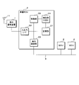
- FIG. 1 is a schematic diagram illustrating a configuration of an in-vehicle system including an in-vehicle ECU 2 according to the first embodiment.
- FIG. 2 is a block diagram illustrating the physical configuration of the vehicle-mounted ECU 2.
- the in-vehicle system S includes a plurality of in-vehicle ECUs 2 mounted on the vehicle C and an in-vehicle device 3 connected to the in-vehicle ECU 2.
- the plurality of vehicle-mounted ECUs 2 are individually connected to the integrated vehicle-mounted ECU 2 (integrated ECU) that controls the entire vehicle C and the integrated vehicle-mounted ECU 2 in a communicable manner and directly connected to the vehicle-mounted device 3. It may include ECU 2 (individual ECU).
- the integrated in-vehicle ECU 2 may be communicably connected to an external server 100 connected to an external network such as the Internet via an external communication device 1.
- the integrated in-vehicle ECU 2 and a plurality of individual in-vehicle ECUs 2 are communicably connected by an in-vehicle network 4 forming a star-shaped network topology, and the integrated in-vehicle ECU 2 is , Is located at the center of the star-shaped network topology. Further, adjacent individual vehicle-mounted ECUs 2 may be connected to each other to form a loop-shaped network topology, enabling bidirectional communication and achieving redundancy.
- a plurality of individual in-vehicle ECUs 2 are arranged in each area of the vehicle C, and an actuator 30 such as an illumination lamp and an in-vehicle device 3 such as a sensor are directly connected by a wire harness such as a serial cable (direct wire).
- a wire harness such as a serial cable (direct wire).
- the individual vehicle-mounted ECU 2 acquires (receives) a signal (input signal) output from the sensor, and transmits a request signal generated based on the acquired input signal to the integrated vehicle-mounted ECU 2.
- the individual in-vehicle ECU 2 controls the drive of the actuator 30 such as the illumination lamp directly connected to the own ECU based on the control signal transmitted from the integrated in-vehicle ECU 2.
- the individual in-vehicle ECU 2 is an in-vehicle relay device such as a gateway or an ether switch that relays communication between a plurality of in-vehicle devices 3 connected to the individual in-vehicle ECU 2 or communication between the in-vehicle device 3 and another in-vehicle ECU 2. It may be a relay control ECU that functions as.
- the individual in-vehicle ECU 2 distributes and relays the electric power output from the power storage device 5 in addition to relaying communication, and also functions as a power distribution device to supply the in-vehicle device 3 connected to the own ECU (Power Lan). Box) may be used.
- the integrated in-vehicle ECU 2 generates and outputs a control signal to each in-vehicle device 3 based on data from the in-vehicle device 3 relayed via another in-vehicle ECU 2 such as an individual in-vehicle ECU 2.
- a central control device such as a vehicle computer.
- the integrated in-vehicle ECU 2 controls to control the actuator 30 that is the target of the request signal based on information or data such as a request signal output (transmitted) from another in-vehicle ECU 2 such as an individual in-vehicle ECU 2.
- a signal is generated, and the generated control signal is output (transmitted) to another vehicle-mounted ECU 2.
- the in-vehicle system is configured by the integrated in-vehicle ECU 2 (integrated ECU) and the individual in-vehicle ECU 2 (individual ECU), but the present invention is not limited thereto.
- the in-vehicle system may be composed of a plurality of in-vehicle ECUs 2 connected peer-to-peer by a relay device such as a CAN (Controller Area Network) gateway or an ether switch.
- a relay device such as a CAN (Controller Area Network) gateway or an ether switch.
- the in-vehicle device 3 includes, for example, various sensors 31 such as LiDAR (Light Detection and Ringing), a light sensor, a CMOS camera, an infrared sensor, a door SW (switch), a switch such as a lamp SW, a lamp, a door opening / closing device, a motor device, and the like. Includes the actuator 30 of.
- sensors 31 such as LiDAR (Light Detection and Ringing), a light sensor, a CMOS camera, an infrared sensor, a door SW (switch), a switch such as a lamp SW, a lamp, a door opening / closing device, a motor device, and the like.
- sensors 31 such as LiDAR (Light Detection and Ringing), a light sensor, a CMOS camera, an infrared sensor, a door SW (switch), a switch such as a lamp SW, a lamp, a door opening / closing device, a motor device
- the external server 100 is a computer such as a server connected to an external network such as the Internet or a public line network, and includes a storage unit such as a RAM (RandomAccessMemory), a ROM (ReadOnlyMemory), or a hard disk.
- the integrated in-vehicle ECU 2 integrated ECU is communicably connected to the external communication device 1 and communicates with the external server 100 connected via the external network via the external communication device 1, and communicates with the external server 100 and the vehicle. Communication with another vehicle-mounted ECU 2 or vehicle-mounted device 3 mounted on C may be relayed.
- the out-of-vehicle communication device 1 includes an out-of-vehicle communication unit (not shown) and an input / output I / O (not shown) for communicating with the integrated in-vehicle ECU 2 (integrated ECU).
- the out-of-vehicle communication unit is a communication device for wireless communication using mobile communication protocols such as 4G, LTE (Long Term Evolution / registered trademark), 5G, and WiFi, and the antenna 11 connected to the out-of-vehicle communication unit.
- Data is sent and received to and from the external server 100 via the above. Communication between the external communication device 1 and the external server 100 is performed via, for example, a public line network or an external network N such as the Internet.
- the input / output I / F 22 is a communication interface for, for example, serial communication with the vehicle-mounted ECU 2.
- the vehicle-mounted communication device 1 and the vehicle-mounted ECU 2 communicate with each other via a wire harness such as an input / output I / F and a serial cable connected to the input / output I / F.
- the vehicle-mounted communication device 1 is a separate device from the vehicle-mounted ECU 2, and these devices are communicably connected by input / output I / F or the like, but the present invention is not limited to this.
- the vehicle-mounted communication device 1 may be built in the vehicle-mounted ECU 2 as a component of the vehicle-mounted ECU 2.
- the in-vehicle ECU 2 (integrated ECU, individual ECU) includes a control unit 20, a storage unit 21, an input / output I / F 22, an in-vehicle communication unit 23, and a verification unit 24.
- the control unit 20 is configured by a CPU (Central Processing Unit), an MPU (Micro Processing Unit), or the like, and various control processes and various control processes can be performed by reading and executing a control program and data stored in advance in the storage unit 21. It is designed to perform arithmetic processing and the like.
- the control unit 20 is not limited to a software processing unit that performs software processing such as a CPU, and includes a hardware processing unit that performs various control processing and arithmetic processing in hardware processing such as FPGA, ASIC, or SOC. It may be.
- the storage unit 21 is a volatile memory element such as a RAM (RandomAccessMemory), a non-volatile memory element such as a ROM (ReadOnlyMemory), an EEPROM (ElectricallyErasableProgrammableROM), or a flash memory, or a storage device thereof. It is configured by the combination of the above, and the control program and the data to be referred to at the time of processing are stored in advance.
- the control program includes, for example, a plurality of applications such as an application for controlling various in-vehicle devices 3 or an application for performing target recognition for performing automated operation based on output data from a LiDAR or CMOS camera.
- the storage unit 21 includes a non-writable storage area composed of a ROM or the like, and the non-writable storage area contains programs and data necessary for fail-safe processing such as a fail-safe program described later and an alternative signal table 211. It is remembered.
- the input / output I / F 22 is, for example, a communication interface for serial communication, like the input / output I / F 22 of the external communication device 1.
- the vehicle-mounted ECU 2 is communicably connected to the external communication device 1 via a wire harness such as an input / output I / F 22 and a serial cable.
- the in-vehicle communication unit 23 is an input / output interface using, for example, a CAN (Controller Area Network) or Ethernet (Ethernet / registered trademark) communication protocol, and the control unit 20 is connected to the in-vehicle network 4 via the in-vehicle communication unit 23. It communicates with another vehicle-mounted ECU 2 that has been installed.
- CAN Controller Area Network
- Ethernet Ethernet / registered trademark
- the verification unit 24 is, for example, an HSM (Hardware Security Module), and is configured as a device or a module different from the control unit 20 configured by a CPU or the like.
- the verification unit 24 configured by the HSM plays a part in the secure boot process performed when the in-vehicle ECU 2 (own ECU) is started (booted), and a plurality of applications stored in the storage unit 21. It is a functional module that verifies the appropriateness (completeness) or soundness of the software executed when the in-vehicle ECU 2 is started.
- the verification unit 24 verifies the appropriateness (integrity) of software such as an application to be verified by using, for example, a encryption algorithm such as CMAC (Cipher-based Message Authentication Code), which includes a processor for encryption processing. do.
- the verification unit 24 verifies the appropriateness (integrity) of each of the plurality of applications to be verified in the secure boot process (secure boot sequence) performed when the in-vehicle ECU 2 is started, and outputs the verification result for each application.
- the verification result includes a positive verification result indicating that the application is legitimate, or a negative verification result indicating that the application is, for example, falsified and fraudulent.
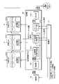
- FIG. 3 is a functional block diagram illustrating a functional unit included in the control unit 20 of the in-vehicle ECU 2.
- the control unit 20 of the in-vehicle ECU 2 functions as an acquisition unit 201, an application activation determination unit 202, a fail-safe unit 203, and an output unit 204 by executing a control program stored in the storage unit 21, and these functional units.
- fail-safe processing is performed. That is, the control unit 20 performs the fail-safe process by cooperating with the verification unit 24 that verifies the application in the secure boot process (secure boot sequence).
- the fail-safe program for causing the control unit 20 to execute the fail-safe process may be stored in the (included) non-rewritable storage area in the storage unit 21.
- By storing the fail-safe program in the non-rewritable storage area it is possible to improve the robustness against attacks (attacks) such as falsification of the fail-safe program from inside and outside the vehicle C, for example.
- the control unit 20 (each functional unit) of the in-vehicle ECU 2 that performs fail-safe processing executes an application whose suitability (integrity) has been verified based on the verification result acquired from the verification unit 24.
- the control unit 20 (does not execute the application whose verification suitability (integrity) has not been verified, and outputs an alternative signal (fail-safe value) for substituting the application that has not been executed.
- the acquisition unit 201 acquires the verification result (verification result) by the verification unit 24 performed as a part of the secure boot process from the verification unit 24.
- the verification result output from the verification unit 24 includes whether the verification result for each application is a positive result or a negative result. If the result is positive, no unauthorized processing such as falsification is performed on the positive application, and the appropriateness (integrity) of the application is guaranteed. If the result is negative, there is a possibility that the negative application has been tampered with or otherwise fraudulently processed, and the appropriateness (integrity) of the application is denied.
- the acquisition unit 201 outputs the acquired verification result to the application activation determination unit 202 and the fail-safe unit 203.
- the application launch determination unit 202 determines whether or not each application can be executed (launched) based on the verification result, and executes the application that can be executed (positive verification result). By executing the application, a process or thread corresponding to the application is created.
- the application start determination unit 202 executes (starts) a positive application and does not execute (start) a negative application. Since the appropriateness (integrity) of the application to be executed is guaranteed, the soundness of the in-vehicle ECU 2 in which a plurality of applications are executed can be ensured.
- the fail-safe unit 203 identifies an application whose verification result is negative based on the verification result.
- the verification result output from the verification unit 24 includes a positive verification result or a negative verification result for each of the plurality of applications.
- the fail-safe unit 203 compares (differences) with a plurality of applications stored in the storage unit 21. By doing so, it is possible to identify the application with a negative verification result.
- the identification of negative applications is roughly classified into the cases where there are no negative applications, the case where there is one negative application, and the case where there are multiple negative applications. In each of these cases, the combination of such negative applications will be identified. That is, the combination of the negative applications is not limited to the combination of two or more applications, and includes the fact that there is no single application or a negative application.
- the fail-safe unit 203 refers to, for example, the pattern information stored in the storage unit 21 based on the combination of the specified negative applications, and substitutes an alternative signal for substituting the negative application that has not been executed. Fail-safe value) is generated.
- the pattern information may be stored, for example, as table format data (alternative signal table 211) in a non-rewritable storage area included in the storage unit 21 as in the fail-safe program.
- FIG. 4 is an explanatory diagram illustrating the alternative signal table 211 (pattern information).
- the alternative signal table 211 includes, as management items, an item of each name of the application executed by the control unit 20 of the vehicle-mounted ECU 2 and an item of the pattern of the alternative signal.
- each application has a positive verification result (shown by ⁇ ) or a negative verification result (shown by ⁇ ).
- a value indicating the existence is stored.
- the alternative signal table 211 includes all combination patterns (all coverage patterns) when all applications are positive ( ⁇ ) or negative (x).
- the individual combinations correspond to the combinations of applications for which the verification result is negative.
- the combination is not limited to a combination of two or more applications, and includes a single application.
- the alternative signal pattern is stored in the alternative signal pattern item, which corresponds to the combination (negative application combination).
- the alternative signal pattern may be, for example, indicated by a predefined value (fail-safe value).
- the fail-safe unit 203 identifies the negative application based on the negative application specified based on the verification result, and by referring to the pattern information (alternative signal table 211), substitutes according to the combination of the specified applications. Derivation (extraction) of the signal pattern (fail-safe value).
- the fail-safe unit 203 generates an alternative signal based on the derived alternative signal pattern (fail-safe value) and outputs it to the output unit 204.
- the fail-safe unit 203 generates the alternative signal based on the data output when the application to be substituted is operating normally when generating the alternative signal based on the alternative signal pattern (fail-safe value). There may be. Alternatively, a signal predetermined based on the functional specifications of the application to be replaced may be generated as a substitute signal.
- the fail-safe unit 203 transmits the derived alternative signal pattern (fail-safe value) to the external server 100 via the external communication device 1, and the external server 100 generates the alternative signal pattern (fail-safe value). It may be generated as the alternative signal by acquiring the alternative signal.
- the output unit 204 outputs the alternative signal generated by the fail-safe unit 203 to the other vehicle-mounted ECU 2 via the in-vehicle communication unit 23.
- the output unit 204 outputs the alternative signal generated by the fail-safe unit 203 to the process of the application (running application) executed by the own ECU, for example, by performing interprocess communication. It may be (transmitted).
- the other in-vehicle ECU 2 that has acquired (received) the alternative signal output (transmitted) from the output unit 204, or the application being executed by the own ECU, performs predetermined processing based on the alternative signal. As a result, it is possible to efficiently replace the application that could not be started due to the verification result of secure boot.
- the predetermined process may include, for example, a process of performing degenerate operation with a partially limited function, or a process of appropriately transitioning the vehicle C to a stopped state.
- the acquisition unit 201, the application activation determination unit 202 fail-safe unit 203, and the output unit 204 have been described as functional units in the control unit 20 of the in-vehicle ECU 2, but the present invention is not limited thereto.
- Some of the functional units in these functional units, or part of the processing in a single functional unit, are separate from the cloud server such as the external server 100 or the control unit 20 that is communicably connected to the in-vehicle ECU 2. It may be carried by the configured verification unit 24.
- the control unit 20 may cooperate with the external server 100 or the verification unit 24 to perform a series of processes by the functional unit.
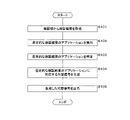
- FIG. 5 is a flowchart illustrating the processing of the control unit 20 of the in-vehicle ECU 2.
- the control unit 20 of the vehicle-mounted ECU 2 is, for example, when the vehicle-mounted ECU 2 (own ECU) is started (booted) when the vehicle C transitions from a stopped state (IG switch is off) to a started state (IG switch is on).
- the following processing is performed based on the secure boot processing (secure boot sequence) performed in.
- the first thing that is performed in the secure boot process is verification for each application by the verification unit 24.
- the verification unit 24 is, for example, an HSM (Hardware Security Module), and is configured as a device or a module different from the control unit 20 configured by a CPU or the like.
- the series of processes by the control unit 20 of the in-vehicle ECU 2 is performed after the verification process for each application by the verification unit 24.
- the control unit 20 of the in-vehicle ECU 2 acquires the verification result from the verification unit 24 (S101).
- the verification result output from the verification unit 24 includes whether the verification result for each application is a positive result or a negative result. If the result is positive, no unauthorized processing such as falsification is performed on the positive application, and the appropriateness (integrity) of the application is guaranteed. If the result is negative, there is a possibility that the negative application has been tampered with or otherwise fraudulently processed, and the appropriateness (integrity) of the application is denied.
- the control unit 20 of the in-vehicle ECU 2 can grasp whether the verification result of each application is positive or negative.
- the control unit 20 of the in-vehicle ECU 2 executes (starts) an application with a positive verification result based on the acquired verification result (S102). Based on the verification result, the control unit 20 of the in-vehicle ECU 2 identifies (determines) an application with a positive verification result as an executable application, and executes the application. By executing an application, a process or thread corresponding to the application is created.
- the control unit 20 of the in-vehicle ECU 2 identifies an application with a negative verification result based on the acquired verification result (S103). Based on the acquired verification result, the control unit 20 of the in-vehicle ECU 2 identifies (determines) an application with a negative verification result as an unexecutable application, and does not execute the application.
- the control unit 20 of the in-vehicle ECU 2 generates an alternative signal corresponding to the application with a negative verification result (S104).
- the control unit 20 of the in-vehicle ECU 2 refers to, for example, the alternative signal table 211 stored in the storage unit 21 to derive an alternative signal pattern (fail-safe value) corresponding to the specified combination of applications.
- the control unit 20 of the in-vehicle ECU 2 generates an alternative signal based on the derived alternative signal pattern (fail-safe value).
- the control unit 20 of the in-vehicle ECU 2 outputs the generated alternative signal (S105).
- the control unit 20 of the vehicle-mounted ECU 2 outputs (transmits) the generated alternative signal to another vehicle-mounted ECU 2 or an application being executed by the own ECU.
- the other in-vehicle ECU 2 that has acquired (received) the alternative signal, or the application being executed by the own ECU has a process of performing degenerate operation based on the alternative signal, a process of appropriately transitioning the vehicle C to a stopped state, or the like. It may perform a predetermined process.
- the control unit 20 of the in-vehicle ECU 2 executes a fail-safe process including a process of outputting a substitute signal corresponding to a negative application, so that there is an application that could not be executed (started) due to the verification result of the secure boot. Even in such a case, it is possible to efficiently substitute the application that has not been executed.
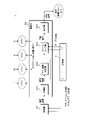
- FIG. 6 is a block diagram illustrating a logical configuration of the vehicle-mounted ECU 2 according to the second embodiment (virtual environment).
- the vehicle-mounted ECU 2 of the second embodiment is different from the first embodiment in that the application is executed in a virtual environment.
- the vehicle-mounted ECU 2 of the second embodiment includes a control unit 20, a storage unit 21, an input / output I / F 22, an in-vehicle communication unit 23, and a verification unit 24, similarly to the vehicle-mounted ECU 2 of the first embodiment. That is, the hardware configurations of the vehicle-mounted ECU 2 of the first embodiment and the vehicle-mounted ECU 2 of the second embodiment are the same.
- the illustration in this embodiment illustrates the logical configuration of the vehicle-mounted ECU 2 of the second embodiment, and is an application executed in a virtual environment with the hardware layer (physical substrate) by the control unit 20 or the like as the lowest layer.
- It is a block diagram which illustrates the hierarchical structure with the software layer as the uppermost layer by a fail-safe program, a virtual environment management program, and the like.
- a virtual operating system such as Hypervisor or VMware is stored in the storage unit 21 of the vehicle-mounted ECU 2, and the control unit 20 of the vehicle-mounted ECU 2 is activated by using the virtual operating system on the virtual operating system.
- the virtualization method is a hypervisor method in which a hardware resource such as a control unit 20 is directly accessed by a virtual operating system as shown in the figure of the present embodiment, or a Linux (Linux) between the virtual operating system and the hardware resource. It may be a host OS system in which an operating system such as (registered trademark) intervenes.
- the in-vehicle ECU 2 activated by using the virtual operating system can construct a plurality of virtual environments by the function of the virtual operating system, and the plurality of virtual environments include hardware resources such as a control unit 20 included in the in-vehicle ECU 2. Assigned. Each of the virtual environments to which these hardware resources are assigned includes a virtual control unit 20 (virtual control unit), a storage unit 21 (virtual storage unit), and an in-vehicle communication unit 23 (virtual in-vehicle communication unit). Functions as ECU 2051.
- the verification unit 24, which is a separate device from the control unit 20, is not subject to virtualization by the virtual operating system, and the verification unit 24 communicates with any virtual ECU 2051 or an individual virtual ECU 2051.
- a guest OS (Operation System) such as Ubuntu (registered trademark) is stored in each virtual storage unit of each virtual ECU 2051, and each virtual ECU 2051 activates a guest OS and executes an application on the guest OS.
- the guest OS may be a different type of OS depending on the individual virtual ECU 2051. As described above, since the substance of the virtual storage unit is the storage area of the storage unit 21 assigned to each of the virtual ECU 2051, it goes without saying that the guest OS is also stored in the storage unit 21 in the same manner as the virtual operating system.
- the control unit 20 of the in-vehicle ECU 2 activated by using the virtual operating system is a program (virtual environment management program) that manages all virtual environments in one of the constructed virtual environments (virtual ECU 2051). ) Is executed. That is, the virtual ECU 2051 that executes the virtual environment management program functions as a control panel of the virtual operating system.
- the fail-safe program for executing the fail-safe process may be executed in the virtual ECU 2051 (virtual environment) that functions as the control panel.
- the virtual ECU 2051 that executes the fail-safe program communicates with the verification unit 24, and acquires the verification result performed by the verification unit 24 in the secure boot process from the verification unit 24.
- FIG. 7 is a functional block diagram illustrating a functional unit included in the control unit 20 of the in-vehicle ECU 2.
- the control unit 20 of the in-vehicle ECU 2 serves as the acquisition unit 201, the application activation determination unit 202, the fail-safe unit 203, and the output unit 204, as in the first embodiment. It functions, and further functions as a virtual environment generation determination unit 205, and performs fail-safe processing.
- the fail-safe program for performing the fail-safe process is, for example, a control unit 20 (virtual control unit) and a storage unit 21 (virtual control unit) of the virtual ECU 2051 (virtual environment) that functions as a control panel of a virtual operating system. It will be executed by using the virtual storage unit) and the in-vehicle communication unit 23 (virtual in-vehicle communication unit). That is, each functional unit such as the acquisition unit 201 illustrated in the present embodiment is configured by the control unit 20 (virtual control unit) of the virtual ECU 2051 (virtual environment) executing the fail-safe program. ..
- the verification unit 24 of the second embodiment verifies each application in the same manner as the verification unit 24 of the first embodiment, and also verifies each guest OS that is started when creating each virtual environment, and the result of the verification ( The verification result) is output to the acquisition unit 201. Therefore, the verification result includes the verification result (positive or negative) of each application and the verification result (positive or negative) of each guest OS.
- the acquisition unit 201 outputs the verification result acquired from the verification unit 24 to the virtual environment generation determination unit 205, the application activation determination unit 202, and the fail-safe unit 203.
- the virtual environment generation determination unit 205 starts the guest OS with a positive verification result to generate a virtual environment with the positive guest OS, and does not start the guest OS with a negative verification result. Do not create a virtual environment with the negative guest OS. Therefore, the appropriateness (integrity) for each of these virtual environments (guest OS) can be guaranteed.
- the application start determination unit 202 sets the virtual environment by the guest OS with the positive verification result as the operating environment, and executes (starts) the application with the positive verification result. Since a negative virtual environment is not generated, the application that uses the negative virtual environment as the operating environment will not be executed either. That is, even if the verification result of the application itself is positive, if the guest OS of the virtual environment that is the operating environment of the application is a negative verification result, the positive application is not executed.
- the application start determination unit 202 operates in association with a virtual environment (guest OS) and one or more applications whose operating environment is a virtual environment in specifying an application whose operating environment is the negative virtual environment.
- the application may be specified by referring to the environment information.
- the operating environment information may be stored, for example, as table format data (operating environment table 212) in a non-rewritable storage area included in the storage unit 21 as in the alternative signal table 211.
- FIG. 8 is an explanatory diagram illustrating the operating environment table 212 (operating environment information).
- the operating environment table 212 includes an application name item and a virtual environment (guest OS) as management items.
- the application name item the names of a plurality of applications executed by the in-vehicle ECU 2 are stored.
- the virtual environment (guest OS) item the name of the virtual environment (guest OS) that is the operating environment of the corresponding application (application stored in the same record) is stored.
- the application start determination unit 202 can acquire the relationship between the virtual environment (guest OS) and the application whose operating environment is the virtual environment by referring to the operating environment table 212. Based on the verification result, the application start determination unit 202 identifies the guest OS having a positive verification result, and by referring to the operating environment table 212, identifies the application whose operating environment is the virtual environment of the specified guest OS. do. In the specified application, the application with a more positive verification result is specified as an executable application. The application start determination unit 202 executes the specified executable application in the virtual environment (guest OS) that is the operating environment of these applications.
- the fail-safe unit 203 identifies the non-executable application and generates an alternative signal corresponding to the specified non-executable application.
- the fail-safe unit 203 identifies the guest OS with a negative verification result based on the verification result, and by referring to the operating environment table 212, the application whose operating environment is the virtual environment of the guest OS with the negative verification result. To identify.
- the fail-safe unit 203 cannot be executed in the same manner as in the first embodiment based on the specified application (application whose operating environment is the virtual environment of the negative guest OS) and the application of the negative verification result included in the verification result. Identify different application combinations.
- the fail-safe unit 203 refers to the alternative signal table 211 as in the first embodiment, and derives an alternative signal pattern (fail-safe value) corresponding to the combination of unexecutable applications.
- the fail-safe unit 203 generates an alternative signal based on the alternative signal pattern (fail-safe value) derived in the same manner as in the first embodiment, and outputs the alternative signal to the output unit 204.
- the output unit 204 outputs (transmits) the alternative signal generated by the fail-safe unit 203 to the other vehicle-mounted ECU 2 or the application being executed by the own ECU, as in the first embodiment.
- FIG. 9 is a flowchart illustrating the processing of the control unit 20 of the in-vehicle ECU 2.
- the control unit 20 of the vehicle-mounted ECU 2 is, for example, when the vehicle-mounted ECU 2 (own ECU) is started (booted) when the vehicle C transitions from a stopped state (IG switch is off) to a started state (IG switch is on). The following processing is performed based on the secure boot processing (secure boot sequence) performed in.
- the fail-safe program for executing the process (fail-safe process) is executed in the virtual ECU 2051 (virtual environment) that functions as the control panel of the virtual operating system
- the control unit 20 is the control unit of the virtual ECU 2051. Corresponds to 20 (virtual control unit).
- the verification unit 24 of the second embodiment verifies not only the application but also the guest OS that is started when the virtual environment is generated.
- the series of processes by the control unit 20 of the in-vehicle ECU 2 is performed after the verification process for each of the guest OS and the application by the verification unit 24.
- the control unit 20 of the in-vehicle ECU 2 acquires the verification result from the verification unit 24 (S201).
- the control unit 20 of the in-vehicle ECU 2 performs the processing of S201 in the same manner as S101 of the first embodiment.
- the verification result output from the verification unit 24 includes the verification result (positive or negative) of each application and the verification result (positive or negative) of each guest OS, and the control unit 20 of the in-vehicle ECU 2 Can acquire the verification results of the application and the guest OS.
- the control unit 20 of the in-vehicle ECU 2 activates the guest OS with a positive verification result based on the acquired verification result to generate a virtual environment (S202). Based on the verification result, the control unit 20 of the in-vehicle ECU 2 activates the guest OS having a positive verification result and creates a virtual environment by the positive guest OS. The control unit 20 of the in-vehicle ECU 2 does not start the guest OS as a negative verification result, and does not generate a virtual environment by the negative guest OS.
- the control unit 20 of the in-vehicle ECU 2 sets the virtual environment by the guest OS with the positive verification result as the operating environment, and executes (starts) the application with the positive verification result (S203).
- the control unit 20 of the in-vehicle ECU 2 identifies a guest OS having a positive verification result based on the verification result, and by referring to the operating environment table 212, specifies an application whose operating environment is the virtual environment of the specified guest OS. do.
- the control unit 20 further identifies an application with a positive verification result in the specified application as an executable application. That is, an application that operates a virtual environment by a guest OS with a positive verification result and further has a positive verification result is specified as an executable application.
- the control unit 20 of the in-vehicle ECU 2 executes the specified application in each corresponding virtual environment.
- the control unit 20 of the in-vehicle ECU 2 identifies a guest OS with a negative verification result based on the acquired verification result (S204).
- the verification result includes the verification result of each guest OS, and the control unit 20 of the vehicle-mounted ECU 2 identifies the guest OS having a negative verification result based on the acquired verification result.
- the control unit 20 of the in-vehicle ECU 2 identifies an unexecutable application based on the acquired verification result and the specified negative verification result guest OS (S205).
- the non-executable application is an application whose operating environment is a virtual environment by a guest OS with a negative verification result, and an application with a negative verification result.
- the control unit 20 of the in-vehicle ECU 2 refers to, for example, the operating environment table 212 stored in the storage unit 21 and identifies a single or a plurality of applications whose operating environment is a virtual environment by the guest OS with a negative verification result. do.
- the control unit 20 of the in-vehicle ECU 2 refers to an application specified by referring to the operating environment table 212 (an application whose operating environment is a virtual environment by a guest OS with a negative verification result), and a negative verification result included in the verification result. Based on the application of the above, the combination of the non-executable applications is specified as in the first embodiment.
- the control unit 20 of the in-vehicle ECU 2 generates an alternative signal corresponding to an unexecutable application (S206).
- the control unit 20 of the in-vehicle ECU 2 refers to the alternative signal table 211 as in the process S104 of the first embodiment, and derives an alternative signal pattern (fail-safe value) corresponding to the combination of unexecutable applications.
- the control unit 20 of the in-vehicle ECU 2 outputs the generated alternative signal (S207).
- the control unit 20 of the vehicle-mounted ECU 2 outputs (transmits) an alternative signal generated in the same manner as the process S105 of the first embodiment to another vehicle-mounted ECU 2 or an application being executed by the own ECU.
- the control unit 20 executes a fail-safe process of generating and outputting an alternative signal that substitutes for an application whose operating environment is a negative virtual environment. Therefore, even in the in-vehicle ECU 2 configured to execute the application as the operating environment in the virtual environment (virtual ECU 2051) generated by the virtual operating system, the application that could not be started due to the verification result of secure boot (not generated). It is possible to efficiently substitute for an application that uses a virtual environment as an operating environment.
Landscapes
- Engineering & Computer Science (AREA)
- Software Systems (AREA)
- Theoretical Computer Science (AREA)
- Computer Security & Cryptography (AREA)
- General Engineering & Computer Science (AREA)
- Physics & Mathematics (AREA)
- General Physics & Mathematics (AREA)
- Computer Hardware Design (AREA)
- Mechanical Engineering (AREA)
- Stored Programmes (AREA)
Abstract
車載ECUは、車両に搭載される車載ECUであって、複数のアプリケーションを実行する制御部と、前記制御部が複数のアプリケーションを実行するにあたり、前記複数のアプリケーションそれぞれの検証を行う検証部とを備え、前記制御部は、前記検証部による検証が肯定的なアプリケーションを実行し、前記検証部による検証が否定的なアプリケーションは実行せず、前記否定的なアプリケーションを代替するフェールセーフ処理を実行し、前記フェールセーフ処理は、前記否定的なアプリケーションを特定し、特定した前記否定的なアプリケーションに応じた代替信号を出力する処理を含む。
Description
本開示は、車載ECU、プログラム及びフェールセーフ方法に関する。
本出願は、2020年11月4日出願の日本出願第2020-184519号に基づく優先権を主張し、前記日本出願に記載された全ての記載内容を援用するものである。
本出願は、2020年11月4日出願の日本出願第2020-184519号に基づく優先権を主張し、前記日本出願に記載された全ての記載内容を援用するものである。
車両には、エンジン制御等のパワー・トレーン系、エアコン制御等のボディ系等の車載機器を制御するためのECU(Electronic Control Unit)が搭載されている。ECUは、MPU等の演算処理部、RAM等の書換可能な不揮発性の記憶部、及び他のECUと通信するための通信部を含み、記憶部に記憶した制御プログラムを読み込んで実行することにより、車載機器の制御を行う。当該制御プログラムを実行するにあたり、ECUの起動時に制御プログラムの完全性を検証し、当該検証に成功した場合にECUの起動(ブート)を許可するセキュアブート方法が、知られている(例えば特許文献1参照)。
特許文献1は、制御プログラムの完全性の検証において、失敗回数が規定値を超えた場合は問題のある制御プログラム(ソフトウェア)を起動しないフェールセーフを行う。
本開示の一態様に係る車載ECUは、車両に搭載される車載ECUであって、複数のアプリケーションを実行する制御部と、前記制御部が複数のアプリケーションを実行するにあたり、前記複数のアプリケーションそれぞれの検証を行う検証部とを備え、前記制御部は、前記検証部による検証が肯定的なアプリケーションを実行し、前記検証部による検証が否定的なアプリケーションは実行せず、前記否定的なアプリケーションを代替するフェールセーフ処理を実行し、前記フェールセーフ処理は、前記否定的なアプリケーションを特定し、特定した前記否定的なアプリケーションに応じた代替信号を出力する処理を含む。
[本開示が解決しようとする課題]
特許文献1のECUは、セキュアブートの検証結果により起動できなかったアプリケーションの代替を行う点が考慮されていないという問題点がある。
特許文献1のECUは、セキュアブートの検証結果により起動できなかったアプリケーションの代替を行う点が考慮されていないという問題点がある。
本開示の目的は、起動できなかったアプリケーションの代替を行うことができる車載ECU等を提供する。
[本開示の効果]
本開示の一態様によれば、起動できなかったアプリケーションの代替を行う車載ECU等を提供することができる。
本開示の一態様によれば、起動できなかったアプリケーションの代替を行う車載ECU等を提供することができる。
[本開示の実施形態の説明]
最初に本開示の実施態様を列挙して説明する。また、以下に記載する実施形態の少なくとも一部を任意に組み合わせてもよい。
最初に本開示の実施態様を列挙して説明する。また、以下に記載する実施形態の少なくとも一部を任意に組み合わせてもよい。
(1)本開示の一態様に係る車載ECUは、車両に搭載される車載ECUであって、複数のアプリケーションを実行する制御部と、前記制御部が複数のアプリケーションを実行するにあたり、前記複数のアプリケーションそれぞれの検証を行う検証部とを備え、前記制御部は、前記検証部による検証が肯定的なアプリケーションを実行し、前記検証部による検証が否定的なアプリケーションは実行せず、前記否定的なアプリケーションを代替するフェールセーフ処理を実行し、前記フェールセーフ処理は、前記否定的なアプリケーションを特定し、特定した前記否定的なアプリケーションに応じた代替信号を出力する処理を含む。
本態様にあたっては、車載ECU(Electronic Control Unit)の制御部は、複数のアプリケーションに対する検証部の検証結果に基づき、複数のアプリケーションそれぞれの実行可否(起動判定)を行うものであり、当該車載ECUにおいては、セキュアブートが行われるものとなる。当該セキュアブートの一端を担う検証部により否定的な検証結果となったアプリケーションを、制御部は実行しないため、車載ECUにおいて実行されるアプリケーションの適正性(完全性)を担保することができる。更に、車載ECUの制御部は、否定的なアプリケーションに応じた代替信号を出力する処理を含むフェールセーフ処理を実行することにより、セキュアブートの検証結果により起動できなかったアプリケーションの代替を効率的に行うことができる。
(2)本開示の一態様に係る車載ECUは、前記フェールセーフ処理を実行するためのフェールセーフプログラムは、書換不可の記憶領域に記憶されている。
本態様にあたっては、車載ECUが備える記憶部において、フェールセーフ処理を実行するためのフェールセーフプログラムは、書換不可の記憶領域に記憶されているため、例えば、車両内外から当該フェールセーフプログラムへの改竄等の攻撃(アタック)に対する堅牢性を向上させることができる。
(3)本開示の一態様に係る車載ECUは、前記書換不可の記憶領域には、前記アプリケーションの組み合わせと、前記代替信号に関する情報とが関連付けられたパターン情報が記憶されており、前記制御部による前記フェールセーフ処理は、前記パターン情報を参照して、特定した前記否定的なアプリケーションに応じた代替信号を出力する処理を含む。
本態様にあたっては、車載ECUの制御部は複数のアプリケーションを実行するところ、検証部の検証結果によって、単一のアプリケーションのみが否定的な検証結果となる場合もあり、又は複数のアプリケーションが否定的な検証結果となる場合もある。これに対し、車載ECUの記憶領域に記憶されているパターン情報は、当該複数のアプリケーションにおける各アプリケーションの組み合わせと、当該組み合わせに関連付けられた代替信号に関する情報とを含む。当該アプリケーションの組み合わせは、2つ以上のアプリケーションの組み合わせに限定されず、単一のアプリケーションについても含む。従って、車載ECUの制御部は、特定したアプリケーションが単一の場合のみならず、複数である場合であっても、パターン情報を参照することにより、当該特定した単数又は複数のアプリケーションの組み合わせに応じた代替信号に関する情報を効率的に取得し、当該情報に基づき代替信号を出力することができる。
(4)本開示の一態様に係る車載ECUは、前記制御部による代替信号を出力する処理は、実行された肯定的なアプリケーションに対し代替信号を出力する処理を含む。
本態様にあたっては、車載ECUの制御部は実行される複数のアプリケーションは、これらアプリケーション間にて、例えばプロセス間通信を行い協調動作又は依存動作を行う。これに対し、制御部による代替信号を出力する処理は、当該代替信号を自ECU以外の他の車載ECUに出力する処理のみならず、自ECU(制御部)にて実行されるアプリケーション(検証結果が肯定的なアプリケーション)に対しても代替信号を出力する処理を含む。従って、自ECU(車載ECU)において実行されるべき複数のアプリケーションにおいて、これらアプリケーション間にて動作処理の依存性がある場合であっても、制御部は、実行された肯定的なアプリケーションに対し代替信号を出力する。従って、当該車載ECUにおける複数のアプリケーションに対する全体的又は包括的なフェールセーフ処理を行うことができる。
(5)本開示の一態様に係る車載ECUは、前記制御部は、仮想化オペレーティングシステムによって複数の仮想環境を生成し、前記複数のアプリケーションそれぞれは、前記複数の仮想環境のうちのいずれかの仮想環境を動作環境とするものであり、前記検証部は、複数の仮想環境それぞれの検証を行い、前記制御部は、前記検証部による検証が肯定的な仮想環境を生成し、前記検証部による検証が否定的な仮想環境は生成せず、該否定的な仮想環境を動作環境とするアプリケーションを代替する前記フェールセーフ処理を実行する。
本態様にあたっては、車載ECUの制御部は、仮想化オペレーティングシステムによって複数の仮想環境を生成し、複数のアプリケーションそれぞれは、いずれかの仮想環境の上にて実行される。すなわち、複数のアプリケーションそれぞれは、CPU等の物理的なハードウェア環境にて動作するものでなく、仮想化オペレーティングシステムによって生成された仮想環境を動作環境として、実行される。これにより、単一の車載ECU(自ECU)において、生成した仮想環境と同数の仮想ECUを構成することができる。当該仮想環境は、アプリケーションを実行するためのプラットフォームとなるゲストOSを含むところ、検証部は当該仮想環境(ゲストOS)の検証を行い、制御部は、当該検証結果に基づき、肯定的な仮想環境は生成し、否定的な仮想環境は生成しない。従って、これら仮想環境(ゲストOS)それぞれに対する適正性(完全性)を担保することができる。否定的な仮想環境は生成されないため、当該否定的な仮想環境を動作環境とするアプリケーションも実行されないものとなるが、これに対し、制御部は、否定的な仮想環境を動作環境とするアプリケーションを代替するフェールセーフ処理を実行する。従って、仮想化オペレーティングシステムによって生成された仮想環境(仮想ECU)を、動作環境としてアプリケーションを実行するように構成された車載ECUにおいても、セキュアブートの検証結果により起動できなかったアプリケーション(生成されなかった仮想環境を動作環境とするアプリケーション)の代替を、効率的に行うことができる。
(6)本開示の一態様に係る車載ECUは、前記フェールセーフ処理を実行するためのフェールセーフプログラムが記憶される書換不可の記憶領域には、前記仮想環境と、前記仮想環境を動作環境とする一つ以上のアプリケーションとが関連付けられた動作環境情報が記憶されており、前記制御部による前記フェールセーフ処理は、前記動作環境情報を参照して、前記否定的な仮想環境を動作環境とするアプリケーションを特定する処理を含む。
本態様にあたっては、車載ECUの制御部は複数の仮想環境を生成し、生成されたそれぞれの仮想環境においては、単一又は複数のアプリケーションが実行されるところ、書換不可の記憶領域には、仮想環境と、仮想環境を動作環境とする一つ以上のアプリケーションとが関連付けられた動作環境情報が記憶されている。従って、車載ECUの制御部は、当該動作環境情報を参照することにより、否定的な検証結果のため生成しなかった仮想環境を動作環境とするアプリケーションを特定し、例えばパターン情報を参照することにより、特定したアプリケーションに応じた代替信号を出力する処理を効率的に行うことができる。
(7)本開示の一態様に係るプログラムは、車両に搭載され、複数のアプリケーションを実行するコンピュータに、前記複数のアプリケーションそれぞれの検証を行い、前記検証の結果が肯定的なアプリケーションを実行し、前記検証の結果が否定的なアプリケーションは実行せず、前記否定的なアプリケーションを代替するフェールセーフ処理を実行し、前記フェールセーフ処理は、前記否定的なアプリケーションを特定し、特定した前記否定的なアプリケーションに応じた代替信号の出力を含む処理を実行させる。
本態様にあたっては、コンピュータを、起動できなかったアプリケーションの代替を行うことができる車載ECUとして機能させることができる。
(8)本開示の一態様に係るフェールセーフ方法は、車両に搭載され、複数のアプリケーションを実行するコンピュータに、前記複数のアプリケーションそれぞれの検証を行い、前記検証の結果が肯定的なアプリケーションを実行し、前記検証の結果が否定的なアプリケーションは実行せず、前記否定的なアプリケーションを代替するフェールセーフ処理を実行し、前記フェールセーフ処理は、前記否定的なアプリケーションを特定し、特定した前記否定的なアプリケーションに応じた代替信号の出力を含む処理を実行させる。
本態様にあたっては、コンピュータを、起動できなかったアプリケーションの代替を行うことができる車載ECUとして機能させるフェールセーフ方法を提供することができる。
[本開示の実施形態の詳細]
本開示をその実施の形態を示す図面に基づいて具体的に説明する。本開示の実施形態に係る車載ECU2を、以下に図面を参照しつつ説明する。なお、本開示はこれらの例示に限定されるものではなく、請求の範囲によって示され、請求の範囲と均等の意味及び範囲内でのすべての変更が含まれることが意図される。
本開示をその実施の形態を示す図面に基づいて具体的に説明する。本開示の実施形態に係る車載ECU2を、以下に図面を参照しつつ説明する。なお、本開示はこれらの例示に限定されるものではなく、請求の範囲によって示され、請求の範囲と均等の意味及び範囲内でのすべての変更が含まれることが意図される。
(実施形態1)
以下、実施の形態について図面に基づいて説明する。図1は、実施形態1に係る車載ECU2を含む車載システムの構成を例示する模式図である。図2は、車載ECU2の物理構成を例示するブロック図である。車載システムSは、車両Cに搭載される複数の車載ECU2及び、当該車載ECU2に接続される車載装置3を含む。
以下、実施の形態について図面に基づいて説明する。図1は、実施形態1に係る車載ECU2を含む車載システムの構成を例示する模式図である。図2は、車載ECU2の物理構成を例示するブロック図である。車載システムSは、車両Cに搭載される複数の車載ECU2及び、当該車載ECU2に接続される車載装置3を含む。
複数の車載ECU2は、車両Cの全体を制御する統合的な車載ECU2(統合ECU)、及び当該統合的な車載ECU2と通信可能に接続され、車載装置3と直接、接続される個別的な車載ECU2(個別ECU)を含むものであってもよい。統合的な車載ECU2は、車外通信装置1を介して、インターネット等の外部ネットワークに接続される外部サーバ100と、通信可能に接続されるものであってもよい。本実施形態において図示においては、統合的な車載ECU2と、複数の個別的な車載ECU2とは、スター状のネットワークトポロジーを形成する車載ネットワーク4によって通信可能に接続され、当該統合的な車載ECU2は、スター状のネットワークトポロジーの中心(センター)に位置して設けられている。更に、隣接する個々の個別的な車載ECU2同士が接続され、ループ状のネットワークトポロジーを構成し、双方向通信を可能として冗長化を図るものであってもよい。
複数の個別的な車載ECU2は、車両Cにおける各エリアに配置され、イルミネーションランプ等のアクチュエータ30、及びセンサ等の車載装置3が、シリアルケーブル(じか線)等のワイヤーハーネスにて、直接接続されている。個別的な車載ECU2は、例えば、センサから出力された信号(入力信号)を取得(受信)し、取得した入力信号に基づき生成した要求信号を統合的な車載ECU2に送信する。個別的な車載ECU2は、統合的な車載ECU2から送信された制御信号に基づき、自ECUに直接、接続されたイルミネーションランプ等のアクチュエータ30の駆動制御を行う。個別的な車載ECU2は、当該個別的な車載ECU2に接続される複数の車載装置3間の通信、又は車載装置3と他の車載ECU2との通信を中継するゲートウェイ又はイーサスイッチ等の車載中継装置として機能する中継制御ECUであってもよい。個別的な車載ECU2は、通信に関する中継に加え、蓄電装置5から出力された電力を分配及び中継し、自ECUに接続される車載装置3に供給する電力分配装置としても機能するPLB(Power Lan Box)であってもよい。
統合的な車載ECU2は、個別的な車載ECU2等、他の車載ECU2を介して中継された車載装置3からのデータに基づき、個々の車載装置3への制御信号を生成及び出力するものであり、例えばヴィークルコンピュータ等の中央制御装置である。統合的な車載ECU2は、個別的な車載ECU2等、他の車載ECU2から出力(送信)される要求信号等の情報又はデータに基づき、当該要求信号の対象となるアクチュエータ30を制御するための制御信号を生成し、生成した制御信号を他の車載ECU2に出力(送信)する。本実施形態においては、統合的な車載ECU2(統合ECU)及び個別的な車載ECU2(個別ECU)により車載システムは構成されるとしたがこれに限定されない。車載システムは、例えばCAN(Controller Area Network)ゲートウェイ又はイーサスイッチ等の中継装置によってピアツーピアに接続された複数の車載ECU2によって構成されるものであってもよい。
車載装置3は、例えばLiDAR(Light Detection and Ranging)、ライトセンサ、CMOSカメラ、赤外線センサ等の各種センサ31及び、ドアSW(スイッチ)、ランプSW等のスイッチ、ランプ、ドア開閉装置、モータ装置等のアクチュエータ30を含む。
外部サーバ100は、例えばインターネット又は公衆回線網等の車外ネットワークに接続されているサーバ等のコンピュータであり、RAM(Random Access Memory)、ROM(Read Only Memory)又はハードディスク等による記憶部を備える。統合的な車載ECU2(統合ECU)は、車外通信装置1と通信可能に接続され、車外通信装置1を介して車外ネットワークを介して接続された外部サーバ100と通信し、外部サーバ100と、車両Cに搭載される他の車載ECU2又は車載装置3との間の通信を中継するものであってもよい。
車外通信装置1は、車外通信部(図示せず)及び、統合的な車載ECU2(統合ECU)と通信するための入出力I/F(図示せず)を含む。車外通信部は、4G、LTE(Long Term Evolution/登録商標)、5G、WiFi等の移動体通信のプロトコルを用いて無線通信をするための通信装置であり、車外通信部に接続されたアンテナ11を介して外部サーバ100とデータの送受信を行う。車外通信装置1と外部サーバ100との通信は、例えば公衆回線網又はインターネット等の外部ネットワークNを介して行われる。入出力I/F22は、車載ECU2と、例えばシリアル通信するための通信インターフェイスである。車外通信装置1と車載ECU2とは、入出力I/F及び入出力I/Fに接続されたシリアルケーブル等のワイヤーハーネスを介して相互に通信する。本実施形態では、車外通信装置1は、車載ECU2と別装置とし、入出力I/F等によってこれら装置を通信可能に接続しているが、これに限定されない。車外通信装置1は、車載ECU2の一構成部位として、車載ECU2に内蔵されるものであってもよい。
車載ECU2(統合EUC、個別ECU)は、制御部20、記憶部21、入出力I/F22、車内通信部23及び検証部24を含む。制御部20は、CPU(Central Processing Unit)又はMPU(Micro Processing Unit)等により構成してあり、記憶部21に予め記憶された制御プログラム及びデータを読み出して実行することにより、種々の制御処理及び演算処理等を行うようにしてある。制御部20は、CPU等のソフトウェア処理を行うソフトウェア処理部のみに限定されず、FPGA、ASIC又はSOC等のハードウェア処理にて種々の制御処理及び演算処理等を行うハードウェア処理部を含むものであってもよい。
記憶部21は、RAM(Random Access Memory)等の揮発性のメモリ素子又は、ROM(Read Only Memory)、EEPROM(Electrically Erasable Programmable ROM)若しくはフラッシュメモリ等の不揮発性のメモリ素子、又は、これら記憶デバイスの組み合わせにより構成してあり、制御プログラム及び処理時に参照するデータが予め記憶してある。当該制御プログラムは、例えば、各種の車載装置3を制御するためのアプリケーション、又はLiDAR又はCMOSカメラからの出力データ基づき自動化運転を行うための物標認識を行うアプリケーション等の複数のアプリケーションを含む。これら複数のアプリケーションは、記憶部21に含まれ、RAM等により構成される書込み可能な記憶領域に記憶されているものであってもよい。記憶部21は、ROM等により構成される書込み不可な記憶領域を含み、当該書込み不可な記憶領域には、後述するフェールセーフプログラム、代替信号テーブル211等のフェールセーフ処理に必要なプログラム及びデータが記憶されている。
入出力I/F22は、車外通信装置1の入出力I/F22と同様に、例えばシリアル通信するための通信インターフェイスである。入出力I/F22及びシリアルケーブル等のワイヤーハーネスを介して、車載ECU2は、車外通信装置1と通信可能に接続される。
車内通信部23は、例えばCAN(Controller Area Network)又はイーサネット(Ethernet/登録商標)の通信プロトコルを用いた入出力インターフェイスであり、制御部20は、車内通信部23を介して車載ネットワーク4に接続されている他の車載ECU2と相互に通信する。
検証部24は、例えばHSM(Hardware Security Module)であり、CPU等で構成される制御部20とは別デバイス又は別モジュールとして構成されている。HSMにて構成される検証部24は、車載ECU2(自ECU)が起動(ブート)される際に行われるセキュアブート処理の一端を担うものであり、記憶部21に記憶されている複数のアプリケーション等、車載ECU2の起動において実行されるソフトウェアの適正性(完全性)又は健全性を検証する機能モジュールである。検証部24は、例えば、暗号処理用のプロセッサを含み、例えばCMAC(Cipher-based Message Authentication Code)等の暗号アルゴリズムを用いて、検証対象となるアプリケーション等のソフトウェアの適正性(完全性)を検証する。検証部24は、車載ECU2の起動時に行われるセキュアブート処理(セキュアブートシーケンス)において、検証対象となる複数のアプリケーションそれぞれの適正性(完全性)を検証し、アプリケーションそれぞれに対する検証結果を出力する。当該検証結果は、アプリケーションが正当である旨を示す肯定的検証結果、又はアプリケーションが例えば改竄等され不正である旨を示す否定的検証結果を含む。
図3は、車載ECU2の制御部20に含まれる機能部を例示する機能ブロック図である。車載ECU2の制御部20は、記憶部21に記憶されている制御プログラムを実行することにより、取得部201、アプリ起動判定部202、フェールセーフ部203、及び出力部204として機能し、これら機能部が連関することにより、フェールセーフ処理が行われる。すなわち、制御部20は、セキュアブート処理(セキュアブートシーケンス)にてアプリケーションの検証を行う検証部24と協働することにより、当該フェールセーフ処理を行うものとなる。
フェールセーフ処理を制御部20に実行させるためのフェールセーフプログラムは、記憶部21における(含まれる)書換不可の記憶領域に記憶されているものであってもよい。書換不可の記憶領域にフェールセーフプログラムを記憶することにより、例えば、車両C内外から当該フェールセーフプログラムへの改竄等の攻撃(アタック)に対する堅牢性を向上させることができる。
フェールセーフ処理を行う車載ECU2の制御部20(各機能部)は、検証部24から取得した検証結果に基づき、適正性(完全性)が検証されたアプリケーションを実行する。制御部20(は、検適正性(完全性)が検証されなかったアプリケーションについては実行することなく、当該実行しなかったアプリケーションを代替するための代替信号(フェールセーフ値)を出力する。
取得部201は、セキュアブート処理の一環として行われた検証部24による検証の結果(検証結果)を、当該検証部24から取得する。検証部24から出力される検証結果には、アプリケーションそれぞれに対する検証結果が肯定的な結果であるか、又は否定的な結果であるかが、含まれている。肯定的な結果である場合、当該肯定的なアプリケーションに対する改竄等の不正処理は行われおらず、当該アプリケーションの適正性(完全性)が保証されるものとなる。否定的な結果である場合、当該否定的なアプリケーションに対し改竄等の不正処理が行われた蓋然性があり、当該アプリケーションの適正性(完全性)が否定されるものとなる。取得部201は、取得した検証結果を、アプリ起動判定部202及びフェールセーフ部203に出力する。
アプリ起動判定部202は、検証結果に基づき、個々のアプリケーションの実行(起動)の可否を判定し、実行が可能(肯定的な検証結果)であるアプリケーションを実行する。当該アプリケーションを実行することにより、アプリケーションに対応したプロセス又はスレッドが生成される。アプリ起動判定部202は、肯定的なアプリケーションは実行(起動)し、否定的なアプリケーションは実行(起動)しない。実行されるアプリケーションの適正性(完全性)は保証されているため、複数のアプリケーションが実行される車載ECU2において、当該車載ECU2の健全性を担保することができる。
フェールセーフ部203は、検証結果に基づき、検証結果が否定的なアプリケーションを特定する。検証部24から出力される検証結果には、複数のアプリケーションそれぞれに対する肯定的検証結果又は否定的検証結果が含まれている。又は、当該検証結果には、肯定的な検証結果のアプリケーションに関する情報のみが含まれる場合であっても、フェールセーフ部203は、記憶部21に記憶されている複数のアプリケーションとの対比(差分)を行うことにより、否定的な検証結果のアプリケーションを特定することができる。否定的なアプリケーションの特定においては、否定的なアプリケーションが皆無な場合、否定的なアプリケーションが一つである場合、又は否定的なアプリケーションが複数である場合に大別される。これら各場合において、当該否定的なアプリケーションの組み合わせが、特定されるものとなる。すなわち、当該否定的なアプリケーションの組み合わせは、2つ以上のアプリケーションの組み合わせに限定されず、単一のアプリケーション、又は否定的なアプリケーションが無い旨についても、含まれる。
フェールセーフ部203は、特定した否定的なアプリケーションの組み合わせに基づき、例えば、記憶部21に記憶されているパターン情報を参照し、実行しなかった当該否定的なアプリケーションを代替するための代替信号(フェールセーフ値)を生成する。パターン情報は、例えばテーブル形式のデータ(代替信号テーブル211)として、フェールセーフプログラムと同様に記憶部21に含まれる書換不可の記憶領域に記憶されているものであってもよい。
図4は、代替信号テーブル211(パターン情報)を例示する説明図である。代替信号テーブル211は、管理項目として、車載ECU2の制御部20が実行するアプリケーションそれぞれの名称の項目、及び代替信号のバターンの項目を含む。車載ECU2の制御部20が実行するアプリケーションそれぞれの名称の項目に対し、個々のアプリケーションが、肯定的な検証結果(〇にて図示)であるか、否定的な検証結果(×にて図示)であるかを示す値が格納される。代替信号テーブル211には、全アプリケーションが肯定的(〇)又は否定的(×)である場合における、全ての組み合わせパターン(全網羅パターン)が含まれている。当該個々の組み合わせが、検証結果が否定的なアプリケーションの組み合わせそれぞれに相当する。当該組み合わせは、2つ以上のアプリケーションの組み合わせに限定されず、単一のアプリケーションについても含む。
代替信号のバターンの項目には、当該組み合わせ(否定的なアプリケーションの組み合わせ)に対応する代替信号パターンが、格納されている。代替信号パターンは、例えば、予め定義されている値(フェールセーフ値)によって、示されるものであってもよい。
フェールセーフ部203は、検証結果に基づき特定した否定的なアプリケーションに基づき当該否定的なアプリケーションを特定し、パターン情報(代替信号テーブル211)を参照することにより、特定したアプリケーションの組み合わせに応じた代替信号パターン(フェールセーフ値)を導出(抽出)する。
フェールセーフ部203は、導出した代替信号パターン(フェールセーフ値)に基づき、代替信号を生成し、出力部204に出力する。フェールセーフ部203は、代替信号パターン(フェールセーフ値)に基づき代替信号を生成するにあたり、代替対象となるアプリケーションが正常動作していた際に出力したデータに基づき、当該代替信号を生成するものであってもよい。又は、代替対象となるアプリケーションの機能仕様等に基づき予め定められた信号を、代替信号として生成するものであってもよい。又は、フェールセーフ部203は、導出した代替信号パターン(フェールセーフ値)を、車外通信装置1を介して外部サーバ100に送信し、当該代替信号パターン(フェールセーフ値)に基づき外部サーバ100が生成した代替信号を取得することにより、当該代替信号として生成するものであってもよい。
出力部204は、フェールセーフ部203が生成した代替信号を、車内通信部23を介して他の車載ECU2に出力する。又は、出力部204は、フェールセーフ部203が生成した代替信号を、自ECUにて実行されたアプリケーション(実行中のアプリケーション)に対し、例えばプロセス間通信を行うことにより、当該アプリケーションのプロセスに出力(送信)するものであってもよい。
出力部204から出力(送信)された代替信号を取得(受信)した他の車載ECU2、又は自ECUにて実行中のアプリケーションは、当該代替信号に基づき、所定の処理を行う。これにより、セキュアブートの検証結果により起動できなかったアプリケーションの代替を効率的に行うことができる。当該所定の処理は、例えば、機能を一部限定した縮退運転を行う処理、又は車両Cを適切に停止状態に遷移させる処理を含むものであってもよい。
本実施形態において、取得部201、アプリ起動判定部202フェールセーフ部203、及び出力部204は、車載ECU2の制御部20における機能部として説明したが、これに限定されない。これら機能部における一部の機能部、又は単一の機能部における処理の一部は、車載ECU2と通信可能に接続される外部サーバ100等のクラウドサーバ、又は、制御部20とは別体で構成される検証部24が担うものであってもよい。制御部20は、これら外部サーバ100又は検証部24と協働して、当該機能部による一連の処理を行うものであってもよい。
図5は、車載ECU2の制御部20の処理を例示するフローチャートである。車載ECU2の制御部20は、例えば、車両Cが停止状態(IGスイッチがオフ)から起動状態(IGスイッチがオン)に状態遷移するにあたり、車載ECU2(自ECU)が起動(ブート)される際に行われるセキュアブート処理(セキュアブートシーケンス)に基づき、以下の処理を行う。
セキュアブート処理において最初に行われるのは、検証部24によるアプリケーションそれぞれに対する検証である。当該検証部24は、例えばHSM(Hardware Security Module)であり、CPU等で構成される制御部20とは別デバイス又は別モジュールとして構成されている。車載ECU2の制御部20による一連の処理は、検証部24によるアプリケーションそれぞれに対する検証の処理後に行われる。
車載ECU2の制御部20は、検証部24から検証結果を取得する(S101)。検証部24から出力される検証結果には、アプリケーションそれぞれに対する検証結果が肯定的な結果であるか、又は否定的な結果であるかが、含まれている。肯定的な結果である場合、肯定的なアプリケーションに対する改竄等の不正処理は行われおらず、当該アプリケーションの適正性(完全性)が保証されるものとなる。否定的な結果である場合、否定的なアプリケーションに対し改竄等の不正処理が行われた蓋然性があり、当該アプリケーションの適正性(完全性)が否定されるものとなる。車載ECU2の制御部20は、検証結果を参照することにより、各アプリケーションの検証結果が肯定的であるか否定的であるかを把握することができる。
車載ECU2の制御部20は、取得した検証結果に基づき、肯定的な検証結果のアプリケーションを実行(起動)する(S102)。車載ECU2の制御部20は、検証結果に基づき、肯定的な検証結果のアプリケーションを実行可能なアプリケーションとして特定(判定)し、当該アプリケーションを実行する。アプリケーションを実行することにより、当該アプリケーションに対応したプロセス又はスレッドが生成される。
車載ECU2の制御部20は、取得した検証結果に基づき、否定的な検証結果のアプリケーションを特定する(S103)。車載ECU2の制御部20は、取得した検証結果に基づき、否定的な検証結果のアプリケーションを実行不可なアプリケーションとして特定(判定)し、当該アプリケーションは実行しない。
車載ECU2の制御部20は、否定的な検証結果のアプリケーションに対応する代替信号を生成する(S104)。車載ECU2の制御部20は、例えば、記憶部21に記憶されている代替信号テーブル211を参照して、特定したアプリケーションの組み合わせに対応する代替信号パターン(フェールセーフ値)を導出する。車載ECU2の制御部20は、導出した代替信号パターン(フェールセーフ値)に基づき、代替信号を生成する。
車載ECU2の制御部20は、生成した代替信号を出力する(S105)。車載ECU2の制御部20は、生成した代替信号を、他の車載ECU2、又は自ECUにて実行中のアプリケーションに出力(送信)する。代替信号を取得(受信)した他の車載ECU2、又は自ECUにて実行中のアプリケーションは、当該代替信号に基づき、縮退運転を行う処理、又は車両Cを適切に停止状態に遷移させる処理等、所定の処理を行うものであってもよい。
本実施形態によれば、セキュアブートの一端を担う検証部24により否定的な検証結果となったアプリケーションは、車載ECU2の制御部20によって実行(起動)されないため、車載ECU2としての健全性を担保することができる。更に、車載ECU2の制御部20は、否定的なアプリケーションに応じた代替信号を出力する処理を含むフェールセーフ処理を実行することにより、セキュアブートの検証結果により実行(起動)できなかったアプリケーションがある場合であっても、当該実行されなかったアプリケーションの代替を効率的に行うことができる。
(実施形態2)
図6は、実施形態2(仮想環境)に係る車載ECU2の論理構成を例示するブロック図である。実施形態2の車載ECU2は、アプリケーションを仮想環境上で実行する点で、実施形態1と異なる。実施形態2の車載ECU2は、実施形態1の車載ECU2と同様に、制御部20、記憶部21、入出力I/F22、車内通信部23及び検証部24を含む。すなわち、実施形態1の車載ECU2と実施形態2の車載ECU2のハードウェア構成は、同様の構成である。本実施形態における図示にて、実施形態2の車載ECU2の論理構成を例示するものであり、制御部20等によるハードウェア層(物理基盤)を最下層とし、仮想環境にて実行されるアプリケーション、フェールセーフプログラム、及び仮想環境管理プログラム等によるソフトウェア層を最上層とした階層構造を例示するブロック図である。
図6は、実施形態2(仮想環境)に係る車載ECU2の論理構成を例示するブロック図である。実施形態2の車載ECU2は、アプリケーションを仮想環境上で実行する点で、実施形態1と異なる。実施形態2の車載ECU2は、実施形態1の車載ECU2と同様に、制御部20、記憶部21、入出力I/F22、車内通信部23及び検証部24を含む。すなわち、実施形態1の車載ECU2と実施形態2の車載ECU2のハードウェア構成は、同様の構成である。本実施形態における図示にて、実施形態2の車載ECU2の論理構成を例示するものであり、制御部20等によるハードウェア層(物理基盤)を最下層とし、仮想環境にて実行されるアプリケーション、フェールセーフプログラム、及び仮想環境管理プログラム等によるソフトウェア層を最上層とした階層構造を例示するブロック図である。
車載ECU2の記憶部21には、例えば、Hypervisor又はVMware等の仮想オペレーティングシステムが記憶されており、車載ECU2の制御部20は、仮想オペレーティングシステムを用いて起動することにより、仮想オペレーティングシステム上にて複数の仮想環境を構築することができる。仮想化の方式は、本実施形態の図示のように仮想オペレーティングシステムによって直接的に制御部20等のハードウェアリソースにアクセスするハイパーバイザー方式、又は仮想オペレーティングシステムとハードウェアリソースとの間にLinux(登録商標)等のオペレーティングシステムが介在するホストOS方式であってもよい。
仮想オペレーティングシステムを用いて起動した車載ECU2は、仮想オペレーティングシステムの機能により、複数の仮想環境を構築することができ、複数の仮想環境には、車載ECU2が備える制御部20等のハードウェアリソースが割り当てられる。これらハードウェアリソースが割り当てられた仮想環境夫々は、仮想的な制御部20(仮想制御部)、記憶部21(仮想記憶部)及び車内通信部23(仮想車内通信部)を備えるものとなり、仮想ECU2051として機能する。制御部20とは別個のデバイである検証部24は、仮想オペレーティングシステムによる仮想化の対象外となり、当該検証部24は、いずれかの仮想ECU2051、又は個々の仮想ECU2051と通信するものとなる。
仮想ECU2051夫々の仮想記憶部夫々には、例えばUbuntu(登録商標)等のゲストOS(Operation System)が記憶され、仮想ECU2051夫々はゲストOSを起動し、当該ゲストOSの上でアプリケーションを実行する。当該ゲストOSは、個々の仮想ECU2051に応じて、異なる種類のOSであってもよい。上述のごとく仮想記憶部の実体は、仮想ECU2051夫々割り当てられた記憶部21の記憶領域であるため、ゲストOSも仮想オペレーティングシステムと同様に記憶部21に記憶されていることは、言うまでもない。
仮想オペレーティングシステムを用いて起動した車載ECU2の制御部20は、構築したいずれかの仮想環境(仮想ECU2051)のうちの一つの仮想ECU2051にて、全ての仮想環境を管理するプログラム(仮想環境管理プログラム)を実行する。すなわち、仮想環境管理プログラムを実行する仮想ECU2051は、仮想オペレーティングシステムのコントロールパネルとして機能する。フェールセーフ処理を実行させるためのフェールセーフプログラムは、当該コントロールパネルとして機能する仮想ECU2051(仮想環境)にて実行されるものであってもよい。当該フェールセーフプログラムを実行する仮想ECU2051は、検証部24と通信し、セキュアブート処理にて検証部24が行った検証結果を、当該検証部24より取得する。
図7は、車載ECU2の制御部20に含まれる機能部を例示する機能ブロック図である。車載ECU2の制御部20は、記憶部21に記憶されている制御プログラムを実行することにより、実施形態1と同様に取得部201、アプリ起動判定部202、フェールセーフ部203、及び出力部204として機能し、更に仮想環境生成判定部205として機能し、フェールセーフ処理を行う。本実施形態における図示において、フェールセーフ処理を行うためのフェールセーフプログラムは、例えば、仮想オペレーティングシステムのコントロールパネルとして機能する仮想ECU2051(仮想環境)の制御部20(仮想制御部)、記憶部21(仮想記憶部)及び車内通信部23(仮想車内通信部)を用いて、実行されるものとなる。すなわち、本実施形態において図示される取得部201等の各機能部は、仮想ECU2051(仮想環境)の制御部20(仮想制御部)がフェールセーフプログラムを実行することにより、構成されるものとなる。
実施形態2の検証部24は、実施形態1の検証部24と同様にアプリケーションそれぞれに対する検証を行うと共に、仮想環境それぞれを生成するにあたり起動されるゲストOSそれぞれに対する検証を行い、当該検証の結果(検証結果)を取得部201に出力する。従って、当該検証結果には、アプリケーションそれぞれの検証結果(肯定的又は否定的)、及びゲストOSそれぞれの検証結果(肯定的又は否定的)が、含まれる。
取得部201は、検証部24から取得した検証結果を、仮想環境生成判定部205、アプリ起動判定部202、及びフェールセーフ部203に出力する。
仮想環境生成判定部205は、検証結果に基づき、肯定的な検証結果のゲストOSは起動して当該肯定的なゲストOSによる仮想環境を生成し、否定的な検証結果のゲストOSは起動せず当該否定的なゲストOSによる仮想環境を生成しない。従って、これら仮想環境(ゲストOS)それぞれに対する適正性(完全性)を担保することができる。
アプリ起動判定部202は、検証結果に基づき、肯定的な検証結果のゲストOSによる仮想環境を動作環境とし、かつ肯定的な検証結果のアプリケーションを実行(起動)する。否定的な仮想環境は生成されないため、当該否定的な仮想環境を動作環境とするアプリケーションも実行されないものとなる。すなわち、アプリケーション自体の検証結果は肯定的であっても、当該アプリケーションの動作環境となる仮想環境のゲストOSが否定的な検証結果である場合は、当該肯定的アプリケーションは、実行されないものとなる。
アプリ起動判定部202は、当該否定的な仮想環境を動作環境とするアプリケーションを特定するにあたり、仮想環境(ゲストOS)と、仮想環境を動作環境とする一つ以上のアプリケーションとが関連付けられた動作環境情報を参照して、当該アプリケーションを特定するものであってもよい。当該動作環境情報は、例えばテーブル形式のデータ(動作環境テーブル212)として、代替信号テーブル211と同様に記憶部21に含まれる書換不可の記憶領域に記憶されているものであってもよい。
図8は、動作環境テーブル212(動作環境情報)を例示する説明図である。動作環境テーブル212は、管理項目として、アプリケーション名称の項目、及び仮想環境(ゲストOS)を含む。アプリケーション名称の項目には、車載ECU2にて実行される複数のアプリケーションの名称が格納される。仮想環境(ゲストOS)の項目には、対応するアプリケーション(同じレコードに格納されるアプリケーション)の動作環境となる仮想環境(ゲストOS)の名称が格納される。
アプリ起動判定部202は、動作環境テーブル212を参照することにより、仮想環境(ゲストOS)と、当該仮想環境を動作環境とするアプリケーションとの関連性を取得することができる。アプリ起動判定部202は、検証結果に基づき、肯定的な検証結果のゲストOSを特定し、動作環境テーブル212を参照することにより、当該特定したゲストOSの仮想環境を動作環境とするアプリケーションを特定する。特定されたアプリケーションにおいて、更に肯定的な検証結果のアプリケーションを、実行可能なアプリケーションとして特定する。アプリ起動判定部202は、特定した実行可能なアプリケーションを、これらアプリケーションの動作環境となる仮想環境(ゲストOS)にて実行する。
フェールセーフ部203は、実行不可なアプリケーションを特定し、当該特定した実行不可なアプリケーションに対応する代替信号を生成する。フェールセーフ部203は、検証結果に基づき否定的な検証結果のゲストOSを特定し、動作環境テーブル212を参照することにより、当該否定的な検証結果のゲストOSの仮想環境を動作環境とするアプリケーションを特定する。フェールセーフ部203は、特定したアプリケーション(否定的なゲストOSの仮想環境を動作環境とするアプリケーション)と、検証結果に含まれる否定的な検証結果のアプリケーションに基づき、実施形態1と同様に実行不可なアプリケーションの組み合わせを特定する。
フェールセーフ部203は、実施形態1と同様に代替信号テーブル211を参照して、実行不可なアプリケーションの組み合わせに対応する代替信号パターン(フェールセーフ値)を導出する。フェールセーフ部203は、実施形態1と同様に導出した代替信号パターン(フェールセーフ値)に基づき、代替信号を生成し、出力部204に出力する。
出力部204は、実施形態1と同様にフェールセーフ部203が生成した代替信号を、他の車載ECU2、又は自ECUにて実行中のアプリケーションに出力(送信)する。
図9は、車載ECU2の制御部20の処理を例示するフローチャートである。車載ECU2の制御部20は、例えば、車両Cが停止状態(IGスイッチがオフ)から起動状態(IGスイッチがオン)に状態遷移するにあたり、車載ECU2(自ECU)が起動(ブート)される際に行われるセキュアブート処理(セキュアブートシーケンス)に基づき、以下の処理を行う。当該処理(フェールセーフ処理)を実行させるためのフェールセーフプログラムが、仮想オペレーティングシステムのコントロールパネルとして機能する仮想ECU2051(仮想環境)にて実行される場合、制御部20は、当該仮想ECU2051の制御部20(仮想制御部)に相当する。
実施形態2の検証部24は、アプリケーションのみならず、仮想環境を生成するにあたり起動されるゲストOSについても検証する。車載ECU2の制御部20による一連の処理は、検証部24によるゲストOS及びアプリケーションそれぞれに対する検証の処理後に行われる。
車載ECU2の制御部20は、検証部24から検証結果を取得する(S201)。車載ECU2の制御部20は、実施形態1のS101と同様にS201の処理を行う。検証部24から出力される検証結果は、アプリケーションそれぞれの検証結果(肯定的又は否定的)、及びゲストOSそれぞれの検証結果(肯定的又は否定的)が含まれており、車載ECU2の制御部20は、アプリケーション及びゲストOSの検証結果を取得することができる。
車載ECU2の制御部20は、取得した検証結果に基づき、肯定的な検証結果のゲストOSを起動して仮想環境を生成する(S202)。車載ECU2の制御部20は、検証結果に基づき、肯定的な検証結果のゲストOSは起動し、当該肯定的なゲストOSによる仮想環境を生成する。車載ECU2の制御部20は、否定的な検証結果のゲストOSは起動せず、当該否定的なゲストOSによる仮想環境を生成しない。
車載ECU2の制御部20は、取得した検証結果に基づき、肯定的な検証結果のゲストOSによる仮想環境を動作環境とし、肯定的な検証結果のアプリケーションを実行(起動)する(S203)。車載ECU2の制御部20は、検証結果に基づき肯定的な検証結果のゲストOSを特定し、動作環境テーブル212を参照することにより、当該特定したゲストOSの仮想環境を動作環境とするアプリケーションを特定する。制御部20は、更に、特定されたアプリケーションにおいて肯定的な検証結果のアプリケーションを、実行可能なアプリケーションとして特定する。すなわち、肯定的な検証結果のゲストOSによる仮想環境を動作環境するアプリケーションであって、更に肯定的な検証結果のアプリケーションが、実行可能なアプリケーションとして特定される。車載ECU2の制御部20は、当該特定したアプリケーションを、対応するそれぞれの仮想環境にて実行させる。
車載ECU2の制御部20は、取得した検証結果に基づき、否定的な検証結果のゲストOSを特定する(S204)。検証結果には、ゲストOSそれぞれの検証結果が含まれており、車載ECU2の制御部20は、取得した検証結果に基づき否定的な検証結果のゲストOSを特定する。
車載ECU2の制御部20は、取得した検証結果及び特定した否定的な検証結果のゲストOSに基づき、実行不可なアプリケーションを特定する(S205)。実行不可なアプリケーションは、否定的な検証結果のゲストOSによる仮想環境を動作環境とするアプリケーション、及び否定的な検証結果のアプリケーションである。車載ECU2の制御部20は、例えば、記憶部21に記憶されている動作環境テーブル212を参照し、否定的な検証結果のゲストOSによる仮想環境を動作環境とする単一又は複数のアプリケーションを特定する。車載ECU2の制御部20は、動作環境テーブル212を参照して特定したアプリケーション(否定的な検証結果のゲストOSによる仮想環境を動作環境とするアプリケーション)、及び検証結果に含まれる否定的な検証結果のアプリケーションに基づき、実施形態1と同様に実行不可なアプリケーションの組み合わせを特定する。
車載ECU2の制御部20は、実行不可なアプリケーションに対応する代替信号を生成する(S206)。車載ECU2の制御部20は、実施形態1の処理S104と同様に代替信号テーブル211を参照して、実行不可なアプリケーションの組み合わせに対応する代替信号パターン(フェールセーフ値)を導出する。
車載ECU2の制御部20は、生成した代替信号を出力する(S207)。車載ECU2の制御部20は、実施形態1の処理S105と同様に生成した代替信号を、他の車載ECU2、又は自ECUにて実行中のアプリケーションに出力(送信)する。
本実施形態においては、否定的な検証結果となった仮想OSによる仮想環境は生成されないため、当該否定的な仮想環境を動作環境とするアプリケーションも実行されないものとなる。これに対し、制御部20は、否定的な仮想環境を動作環境とするアプリケーションを代替する代替信号を生成及び出力するフェールセーフ処理を実行する。従って、仮想化オペレーティングシステムによって生成された仮想環境(仮想ECU2051)を、動作環境としてアプリケーションを実行するように構成された車載ECU2においても、セキュアブートの検証結果により起動できなかったアプリケーション(生成されなかった仮想環境を動作環境とするアプリケーション)の代替を、効率的に行うことができる。
今回開示された実施形態はすべての点で例示であって、制限的なものではないと考えられるべきである。本発明の範囲は、上記した意味ではなく、請求の範囲によって示され、請求の範囲と均等の意味及び範囲内でのすべての変更が含まれることが意図される。
C 車両
S 車載システム
100 外部サーバ
1 車外通信装置
11 アンテナ
2 車載ECU
20 制御部
201 取得部
202 アプリ起動判定部
203 フェールセーフ部
204 出力部
205 仮想環境生成判定部
2051 仮想ECU
21 記憶部
211 代替信号テーブル
212 動作環境テーブル
22 入出力I/F
23 車内通信部
24 検証部
3 車載装置
30 アクチュエータ(ACT)
31 センサ
4 車載ネットワーク
S 車載システム
100 外部サーバ
1 車外通信装置
11 アンテナ
2 車載ECU
20 制御部
201 取得部
202 アプリ起動判定部
203 フェールセーフ部
204 出力部
205 仮想環境生成判定部
2051 仮想ECU
21 記憶部
211 代替信号テーブル
212 動作環境テーブル
22 入出力I/F
23 車内通信部
24 検証部
3 車載装置
30 アクチュエータ(ACT)
31 センサ
4 車載ネットワーク
Claims (8)
- 車両に搭載される車載ECUであって、
複数のアプリケーションを実行する制御部と、
前記制御部が複数のアプリケーションを実行するにあたり、前記複数のアプリケーションそれぞれの検証を行う検証部とを備え、
前記制御部は、
前記検証部による検証が肯定的なアプリケーションを実行し、
前記検証部による検証が否定的なアプリケーションは実行せず、前記否定的なアプリケーションを代替するフェールセーフ処理を実行し、
前記フェールセーフ処理は、
前記否定的なアプリケーションを特定し、
特定した前記否定的なアプリケーションに応じた代替信号を出力する処理を含む
車載ECU。 - 前記フェールセーフ処理を実行するためのフェールセーフプログラムは、書換不可の記憶領域に記憶されている
請求項1に記載の車載ECU。 - 前記書換不可の記憶領域には、前記アプリケーションの組み合わせと、前記代替信号に関する情報とが関連付けられたパターン情報が記憶されており、
前記制御部による前記フェールセーフ処理は、前記パターン情報を参照して、特定した前記否定的なアプリケーションに応じた代替信号を出力する処理を含む
請求項2に記載の車載ECU。 - 前記制御部による代替信号を出力する処理は、実行された肯定的なアプリケーションに対し代替信号を出力する処理を含む
請求項1から請求項3のいずれか1項に記載の車載ECU。 - 前記制御部は、仮想化オペレーティングシステムによって複数の仮想環境を生成し、
前記複数のアプリケーションそれぞれは、前記複数の仮想環境のうちのいずれかの仮想環境を動作環境とするものであり、
前記検証部は、複数の仮想環境それぞれの検証を行い、
前記制御部は、
前記検証部による検証が肯定的な仮想環境を生成し、
前記検証部による検証が否定的な仮想環境は生成せず、該否定的な仮想環境を動作環境とするアプリケーションを代替する前記フェールセーフ処理を実行する
請求項1から請求項4のいずれか1項に記載の車載ECU。 - 前記フェールセーフ処理を実行するためのフェールセーフプログラムが記憶される書換不可の記憶領域には、前記仮想環境と、前記仮想環境を動作環境とする一つ以上のアプリケーションとが関連付けられた動作環境情報が記憶されており、
前記制御部による前記フェールセーフ処理は、前記動作環境情報を参照して、前記否定的な仮想環境を動作環境とするアプリケーションを特定する処理を含む
請求項5に記載の車載ECU。 - 車両に搭載され、複数のアプリケーションを実行するコンピュータに、
前記複数のアプリケーションそれぞれの検証を行い、
前記検証の結果が肯定的なアプリケーションを実行し、
前記検証の結果が否定的なアプリケーションは実行せず、前記否定的なアプリケーションを代替するフェールセーフ処理を実行し、
前記フェールセーフ処理は、
前記否定的なアプリケーションを特定し、
特定した前記否定的なアプリケーションに応じた代替信号の出力を含む
処理を実行させるプログラム。 - 車両に搭載され、複数のアプリケーションを実行するコンピュータに、
前記複数のアプリケーションそれぞれの検証を行い、
前記検証の結果が肯定的なアプリケーションを実行し、
前記検証の結果が否定的なアプリケーションは実行せず、前記否定的なアプリケーションを代替するフェールセーフ処理を実行し、
前記フェールセーフ処理は、
前記否定的なアプリケーションを特定し、
特定した前記否定的なアプリケーションに応じた代替信号の出力を含む
処理を実行させるフェールセーフ方法。
Applications Claiming Priority (2)
| Application Number | Priority Date | Filing Date | Title |
|---|---|---|---|
| JP2020184519A JP2022074461A (ja) | 2020-11-04 | 2020-11-04 | 車載ecu、プログラム及びフェールセーフ方法 |
| JP2020-184519 | 2020-11-04 |
Publications (1)
| Publication Number | Publication Date |
|---|---|
| WO2022097448A1 true WO2022097448A1 (ja) | 2022-05-12 |
Family
ID=81457088
Family Applications (1)
| Application Number | Title | Priority Date | Filing Date |
|---|---|---|---|
| PCT/JP2021/038162 Ceased WO2022097448A1 (ja) | 2020-11-04 | 2021-10-15 | 車載ecu、プログラム及びフェールセーフ方法 |
Country Status (2)
| Country | Link |
|---|---|
| JP (1) | JP2022074461A (ja) |
| WO (1) | WO2022097448A1 (ja) |
Families Citing this family (1)
| Publication number | Priority date | Publication date | Assignee | Title |
|---|---|---|---|---|
| US12566375B2 (en) * | 2021-05-06 | 2026-03-03 | Sumitomo Chemical Company, Limited | Salt, acid generator, resist composition and method for producing resist pattern |
Citations (4)
| Publication number | Priority date | Publication date | Assignee | Title |
|---|---|---|---|---|
| JPH0633828A (ja) * | 1992-07-17 | 1994-02-08 | Nippondenso Co Ltd | 車載用電子制御装置 |
| WO2010097936A1 (ja) * | 2009-02-27 | 2010-09-02 | トヨタ自動車株式会社 | 車両の制御装置 |
| JP2020144531A (ja) * | 2019-03-05 | 2020-09-10 | トヨタ自動車株式会社 | 車両用制御装置、車両用制御装置の起動方法及び記録媒体 |
| JP2020173560A (ja) * | 2019-04-09 | 2020-10-22 | 株式会社オートネットワーク技術研究所 | 車載コンピュータ、コンピュータ実行方法及びコンピュータプログラム |
-
2020
- 2020-11-04 JP JP2020184519A patent/JP2022074461A/ja active Pending
-
2021
- 2021-10-15 WO PCT/JP2021/038162 patent/WO2022097448A1/ja not_active Ceased
Patent Citations (4)
| Publication number | Priority date | Publication date | Assignee | Title |
|---|---|---|---|---|
| JPH0633828A (ja) * | 1992-07-17 | 1994-02-08 | Nippondenso Co Ltd | 車載用電子制御装置 |
| WO2010097936A1 (ja) * | 2009-02-27 | 2010-09-02 | トヨタ自動車株式会社 | 車両の制御装置 |
| JP2020144531A (ja) * | 2019-03-05 | 2020-09-10 | トヨタ自動車株式会社 | 車両用制御装置、車両用制御装置の起動方法及び記録媒体 |
| JP2020173560A (ja) * | 2019-04-09 | 2020-10-22 | 株式会社オートネットワーク技術研究所 | 車載コンピュータ、コンピュータ実行方法及びコンピュータプログラム |
Also Published As
| Publication number | Publication date |
|---|---|
| JP2022074461A (ja) | 2022-05-18 |
Similar Documents
| Publication | Publication Date | Title |
|---|---|---|
| US10353692B2 (en) | Method for updating a control unit for an automotive vehicle, control unit for an automotive vehicle, and computer program product | |
| JP7280412B2 (ja) | ゲートウェイ装置、車載ネットワークシステム及びファームウェア更新方法 | |
| JP6889296B2 (ja) | ゲートウェイ装置、システム及びファームウェア更新方法 | |
| JP7485110B2 (ja) | 代替装置、代替制御プログラム及び代替方法 | |
| US20230409316A1 (en) | In-vehicle ecu, program, and information processing method | |
| WO2017178888A1 (en) | Specially programmed computing systems with associated devices configured to implement secure lockdowns and methods of use thereof | |
| JP7327242B2 (ja) | 車載中継装置、情報処理方法及びプログラム | |
| CN110785757B (zh) | 边缘设备和用于运行边缘设备的方法 | |
| US12050691B2 (en) | Security processing device | |
| CN113885907A (zh) | 一种固件升级系统及方法 | |
| CN113631430B (zh) | 车载计算机、计算机执行方法及计算机程序 | |
| WO2022097448A1 (ja) | 車載ecu、プログラム及びフェールセーフ方法 | |
| JP7463947B2 (ja) | 車載ecu、プログラム、及び情報処理方法 | |
| US12242610B2 (en) | Mitigation of a manipulation of software of a vehicle | |
| JP2023122639A (ja) | 車両のソフトウェアの改竄の軽減 | |
| US20230391345A1 (en) | Performing security functions using devices having embedded hardware security modules | |
| JP7613152B2 (ja) | 車載装置、情報処理方法、及びコンピュータプログラム | |
| JP6698778B2 (ja) | 制御システム | |
| CN110023940A (zh) | 适合于在受保护的和/或开放的运行状态下运行的设备单元以及所属的方法 | |
| CN114662081A (zh) | 车辆的控制装置及控制方法、记录有控制程序的记录介质 | |
| JP2023510122A (ja) | インタフェースを備える装置およびインタフェースを備える装置の動作方法 | |
| US12472961B2 (en) | Vehicle control using serverless functions | |
| CN119550997A (zh) | 生成车辆识别信息的系统、方法以及计算机程序产品 | |
| CN119227077A (zh) | 座舱域控制器系统的安全启动方法、装置、设备及车辆 | |
| JP7025200B2 (ja) | プログラム制御装置、プログラム制御システムおよびプログラム制御方法 |
Legal Events
| Date | Code | Title | Description |
|---|---|---|---|
| 121 | Ep: the epo has been informed by wipo that ep was designated in this application |
Ref document number: 21889001 Country of ref document: EP Kind code of ref document: A1 |
|
| NENP | Non-entry into the national phase |
Ref country code: DE |
|
| 122 | Ep: pct application non-entry in european phase |
Ref document number: 21889001 Country of ref document: EP Kind code of ref document: A1 |