WO2022094112A1 - Biometric parameter measurement - Google Patents
Biometric parameter measurement Download PDFInfo
- Publication number
- WO2022094112A1 WO2022094112A1 PCT/US2021/057093 US2021057093W WO2022094112A1 WO 2022094112 A1 WO2022094112 A1 WO 2022094112A1 US 2021057093 W US2021057093 W US 2021057093W WO 2022094112 A1 WO2022094112 A1 WO 2022094112A1
- Authority
- WO
- WIPO (PCT)
- Prior art keywords
- light
- illuminant
- infrared
- value
- subject
- Prior art date
Links
- 238000005259 measurement Methods 0.000 title claims abstract description 111
- WQZGKKKJIJFFOK-GASJEMHNSA-N Glucose Natural products OC[C@H]1OC(O)[C@H](O)[C@@H](O)[C@@H]1O WQZGKKKJIJFFOK-GASJEMHNSA-N 0.000 claims abstract description 52
- 239000008103 glucose Substances 0.000 claims abstract description 52
- 238000000034 method Methods 0.000 claims abstract description 23
- 210000004369 blood Anatomy 0.000 claims abstract description 16
- 239000008280 blood Substances 0.000 claims abstract description 16
- 238000001914 filtration Methods 0.000 claims description 41
- 230000015654 memory Effects 0.000 claims description 26
- 238000004364 calculation method Methods 0.000 claims description 15
- 230000004044 response Effects 0.000 claims description 13
- 238000007667 floating Methods 0.000 claims description 6
- 230000002596 correlated effect Effects 0.000 claims description 3
- 238000013186 photoplethysmography Methods 0.000 description 9
- 238000003860 storage Methods 0.000 description 9
- 238000005286 illumination Methods 0.000 description 8
- QVGXLLKOCUKJST-UHFFFAOYSA-N atomic oxygen Chemical compound [O] QVGXLLKOCUKJST-UHFFFAOYSA-N 0.000 description 6
- 238000000605 extraction Methods 0.000 description 6
- 230000003287 optical effect Effects 0.000 description 6
- 229910052760 oxygen Inorganic materials 0.000 description 6
- 239000001301 oxygen Substances 0.000 description 6
- 230000036772 blood pressure Effects 0.000 description 5
- 230000008859 change Effects 0.000 description 5
- 230000006854 communication Effects 0.000 description 5
- 238000004891 communication Methods 0.000 description 5
- 238000013480 data collection Methods 0.000 description 5
- 238000012544 monitoring process Methods 0.000 description 5
- 238000012545 processing Methods 0.000 description 5
- 238000004458 analytical method Methods 0.000 description 4
- 238000013459 approach Methods 0.000 description 4
- 230000006870 function Effects 0.000 description 4
- 238000010606 normalization Methods 0.000 description 4
- 230000000875 corresponding effect Effects 0.000 description 3
- 230000003205 diastolic effect Effects 0.000 description 3
- 238000011156 evaluation Methods 0.000 description 3
- 230000002085 persistent effect Effects 0.000 description 3
- 230000004913 activation Effects 0.000 description 2
- 238000001994 activation Methods 0.000 description 2
- 238000010586 diagram Methods 0.000 description 2
- 238000005516 engineering process Methods 0.000 description 2
- 230000036541 health Effects 0.000 description 2
- 230000002093 peripheral effect Effects 0.000 description 2
- 230000008569 process Effects 0.000 description 2
- 238000000926 separation method Methods 0.000 description 2
- 230000003595 spectral effect Effects 0.000 description 2
- 238000003491 array Methods 0.000 description 1
- 210000002565 arteriole Anatomy 0.000 description 1
- 210000001367 artery Anatomy 0.000 description 1
- 230000003190 augmentative effect Effects 0.000 description 1
- 230000009286 beneficial effect Effects 0.000 description 1
- 230000008901 benefit Effects 0.000 description 1
- 230000007175 bidirectional communication Effects 0.000 description 1
- 230000005540 biological transmission Effects 0.000 description 1
- 230000017531 blood circulation Effects 0.000 description 1
- 210000004027 cell Anatomy 0.000 description 1
- 230000000295 complement effect Effects 0.000 description 1
- 206010012601 diabetes mellitus Diseases 0.000 description 1
- 238000009826 distribution Methods 0.000 description 1
- 230000009977 dual effect Effects 0.000 description 1
- 230000002526 effect on cardiovascular system Effects 0.000 description 1
- 210000003743 erythrocyte Anatomy 0.000 description 1
- 229910052736 halogen Inorganic materials 0.000 description 1
- 150000002367 halogens Chemical class 0.000 description 1
- 230000000977 initiatory effect Effects 0.000 description 1
- 230000007774 longterm Effects 0.000 description 1
- 238000000691 measurement method Methods 0.000 description 1
- 230000007246 mechanism Effects 0.000 description 1
- 230000005055 memory storage Effects 0.000 description 1
- QSHDDOUJBYECFT-UHFFFAOYSA-N mercury Chemical compound [Hg] QSHDDOUJBYECFT-UHFFFAOYSA-N 0.000 description 1
- 229910052753 mercury Inorganic materials 0.000 description 1
- 229910044991 metal oxide Inorganic materials 0.000 description 1
- 150000004706 metal oxides Chemical class 0.000 description 1
- 229910052754 neon Inorganic materials 0.000 description 1
- GKAOGPIIYCISHV-UHFFFAOYSA-N neon atom Chemical compound [Ne] GKAOGPIIYCISHV-UHFFFAOYSA-N 0.000 description 1
- 230000000737 periodic effect Effects 0.000 description 1
- 230000000541 pulsatile effect Effects 0.000 description 1
- 238000002106 pulse oximetry Methods 0.000 description 1
- 239000004065 semiconductor Substances 0.000 description 1
- 230000002123 temporal effect Effects 0.000 description 1
- 238000002834 transmittance Methods 0.000 description 1
- 229910052724 xenon Inorganic materials 0.000 description 1
- FHNFHKCVQCLJFQ-UHFFFAOYSA-N xenon atom Chemical compound [Xe] FHNFHKCVQCLJFQ-UHFFFAOYSA-N 0.000 description 1
Classifications
-
- A—HUMAN NECESSITIES
- A61—MEDICAL OR VETERINARY SCIENCE; HYGIENE
- A61B—DIAGNOSIS; SURGERY; IDENTIFICATION
- A61B5/00—Measuring for diagnostic purposes; Identification of persons
- A61B5/145—Measuring characteristics of blood in vivo, e.g. gas concentration, pH value; Measuring characteristics of body fluids or tissues, e.g. interstitial fluid, cerebral tissue
- A61B5/14532—Measuring characteristics of blood in vivo, e.g. gas concentration, pH value; Measuring characteristics of body fluids or tissues, e.g. interstitial fluid, cerebral tissue for measuring glucose, e.g. by tissue impedance measurement
-
- A—HUMAN NECESSITIES
- A61—MEDICAL OR VETERINARY SCIENCE; HYGIENE
- A61B—DIAGNOSIS; SURGERY; IDENTIFICATION
- A61B5/00—Measuring for diagnostic purposes; Identification of persons
- A61B5/0059—Measuring for diagnostic purposes; Identification of persons using light, e.g. diagnosis by transillumination, diascopy, fluorescence
- A61B5/0075—Measuring for diagnostic purposes; Identification of persons using light, e.g. diagnosis by transillumination, diascopy, fluorescence by spectroscopy, i.e. measuring spectra, e.g. Raman spectroscopy, infrared absorption spectroscopy
-
- A—HUMAN NECESSITIES
- A61—MEDICAL OR VETERINARY SCIENCE; HYGIENE
- A61B—DIAGNOSIS; SURGERY; IDENTIFICATION
- A61B5/00—Measuring for diagnostic purposes; Identification of persons
- A61B5/02—Detecting, measuring or recording pulse, heart rate, blood pressure or blood flow; Combined pulse/heart-rate/blood pressure determination; Evaluating a cardiovascular condition not otherwise provided for, e.g. using combinations of techniques provided for in this group with electrocardiography or electroauscultation; Heart catheters for measuring blood pressure
- A61B5/024—Detecting, measuring or recording pulse rate or heart rate
- A61B5/02416—Detecting, measuring or recording pulse rate or heart rate using photoplethysmograph signals, e.g. generated by infrared radiation
-
- A—HUMAN NECESSITIES
- A61—MEDICAL OR VETERINARY SCIENCE; HYGIENE
- A61B—DIAGNOSIS; SURGERY; IDENTIFICATION
- A61B5/00—Measuring for diagnostic purposes; Identification of persons
- A61B5/02—Detecting, measuring or recording pulse, heart rate, blood pressure or blood flow; Combined pulse/heart-rate/blood pressure determination; Evaluating a cardiovascular condition not otherwise provided for, e.g. using combinations of techniques provided for in this group with electrocardiography or electroauscultation; Heart catheters for measuring blood pressure
- A61B5/026—Measuring blood flow
- A61B5/0261—Measuring blood flow using optical means, e.g. infrared light
-
- A—HUMAN NECESSITIES
- A61—MEDICAL OR VETERINARY SCIENCE; HYGIENE
- A61B—DIAGNOSIS; SURGERY; IDENTIFICATION
- A61B5/00—Measuring for diagnostic purposes; Identification of persons
- A61B5/145—Measuring characteristics of blood in vivo, e.g. gas concentration, pH value; Measuring characteristics of body fluids or tissues, e.g. interstitial fluid, cerebral tissue
- A61B5/1455—Measuring characteristics of blood in vivo, e.g. gas concentration, pH value; Measuring characteristics of body fluids or tissues, e.g. interstitial fluid, cerebral tissue using optical sensors, e.g. spectral photometrical oximeters
-
- A—HUMAN NECESSITIES
- A61—MEDICAL OR VETERINARY SCIENCE; HYGIENE
- A61B—DIAGNOSIS; SURGERY; IDENTIFICATION
- A61B5/00—Measuring for diagnostic purposes; Identification of persons
- A61B5/74—Details of notification to user or communication with user or patient ; user input means
- A61B5/746—Alarms related to a physiological condition, e.g. details of setting alarm thresholds or avoiding false alarms
Definitions
- the present invention is directed to apparatus, systems and methods for monitoring or calculating one or more biometric measurements of a patient.
- Photoplethysmography is a noninvasive, low cost, and simple optical measurement technique applied at the surface of the skin to measure physiological parameters. It is known in the field of biometric parameter measurement to use PPG configurations to obtain pulse oximetry and heart rate calculations for a patient. PPG analysis of patient biometric parameters typically include optical measurements that allow for a subject to have his or her heart rate monitored. Typically, PPG uses non-invasive technology that includes a light source and a photodetector at the surface of skin to measure the volumetric variations of blood circulation.
- PPG devices have several drawbacks, including imprecision in measurements. For example, Fine J, Branan KL, Rodriguez AJ, et al.
- the apparatus, systems and methods described are directed to obtaining biometric measurements, including blood glucose levels, using one or more light sources.
- a biometric parameter measurement system comprises at least one visible light illuminant configured to emit light substantially in the red wavelength and at least one infrared illuminant configured to emit light substantially in the infrared wavelength wherein each of the at least one infrared and visible light illuminants are configured to emit light at a subject.
- the system also includes a light measurement device configured to receive, on a light sensing portion thereof, light produced by each of the at least one infrared and visible light illuminants where the received light has been reflected off of the subject.
- the biometric parameter measurement system further includes one or more processors having a memory and configured to receive the output signal from the light measurement device based on each of the at least one infrared and visible light illuminants.
- the biometric parameter measurement system is further configured with one or more processors, configured to execute code therein to calculate a value correlated to the glucose value of the subject.
- the processor is configured to calculate the glucose value by filtering the signal for each of the at least one infrared and visible light illuminants; generating a heartbeat value using at least one infrared and visible light illuminates; and calculating glucose value for the subject based, at least in part on a difference between the filtered at least one infrared and visible light illuminant signals.
- FIG. 1 illustrates devices and components that interface over one or more data communication networks in accordance with one or more implementations of the biometric parameter measurement system.
- FIG. 2 presents a flow diagram detailing the steps taken in one configuration of the biometric parameter measurement system described herein.
- FIG. 3 presents a collection of modules detailing the operative functions of the biometric parameter measurement system according to one configuration.
- FIG. 4 is a graph detailing the waveform analyzed according to the biometric parameter measurement system provided herein.
- FIG. 5 is a flow diagram detailing the determination of biometric parameters of a subject by the biometric parameter measurement system provided herein.
- FIG. 6 is one configuration of the biometric parameter measurement device described herein depicting a measurement of a biometric parameter.
- Fig. 1 illustrates devices and components for obtaining biometric parameter data.
- the biometric parameter measurement system described herein in utilizes a plurality of illuminants and a sensor configured to generate output signals in response to receiving light that has been reflected off of a subject 102.
- Fig. 1 illustrates a subject 102 under analysis by light measurement device 103, or sensor thereof.
- the subject 102 can be any individual seeking information about a biometric parameter.
- the subject 102 is an individual that has exposed his or her skin to the illuminant(s) and sensor configuration described herein.
- the subject 102 is an individual seeking information about the subject’s pulse, blood oxygen level, stress level, glucose level or other biometric parameter that can be obtained using PPG techniques.
- the subject 102 is placed such that the subject 102 can be illuminated by the illuminants described herein.
- the subject 102 is positioned within 1-10 centimeters from the illuminant(s) and sensors.
- the illuminant(s) and sensors are integrated into a watch, band or bracelet worn by the user such that the worn article is in direct contact with the skin of a subject 102.
- the subject 102 is illuminated by two (2) or more different illuminants.
- the illuminant 106A and illuminant 106B are commercially available lighting sources.
- the illuminant 106A and illuminant 106B are separate devices that are configurable to produce a light with certain spectral power distributions and/or wavelengths.
- the illuminant I06A and illuminant 106B are one or more discrete light emitting elements, such as LEDs, OLEDs, fluorescent, halogen, xenon, neon, D65 light, fluorescent lamp, mercury lamp. Metal Halide lamp, HPS lamp, incandescent lamp or other commonly known or understood lighting sources.
- both illuminant 106A and illuminant 106B are narrow-band LEDs or broad-band LEDs.
- the illuminants 106A and illuminant are illuminants 106A and illuminant
- 106B include a lens, filter, screen, enclosure, or other elements (not shown) that are utilized in combination with the light source of the illuminant 106A and illuminant 106B to direct a beam of illumination, at a given wavelength or at a range of wavelengths, to the subject 102.
- illuminant I06A and illuminant 106B are operable or configurable by an internal processor or other control circuit.
- illuminant 106A and illuminant 106B are operable or configurable by a processor (either local or remote) or a control device having one or more linkages or connections to illuminant 106A and illuminant 106B.
- illuminant 106A and illuminant 106B are directly connected to a light measurement device 103.
- Such direct connections can be, in one arrangement, wired or wireless connections.
- illuminant 106A and illuminant 106B are positioned relative to the subject 102 and light measurement device 103 so as to provide a 45/0, d/8, or other illumination/pickup geometry combination.
- any suitable measurement geometry capable of evaluating light reflected off of the subject 102 is understood and appreciated.
- the light measurement device 103 can be a light measurement device, color sensor or image capture device.
- the light measurement device 103 is a scientific CMOS (Complementary Metal Oxide Semiconductor), CCD (charge coupled device), colorimeter, spectrometer, spectrophotometer, photodiode array, or other light sensing device and any associated hardware, firmware and software necessary for the operation thereof.
- the light measurement device 103 is configured to generate an output signal upon light striking the light measurement device 103 or a light sensing portion thereof.
- the light measurement device 103 is configured to output a signal in response to light that has been reflected off of the subject 102 and then strikes a light sensor or other sensor element integral or associated with the light measurement device 103.
- the light measurement device 103 is configured to generate a digital or analog signal that corresponds to the wavelength or wavelengths of light that impact or are incident upon at least a portion of the light measurement device 103 after being reflected off of the subject 102.
- the light measurement device 103 is configured to output spectral information, RGB information, or another form of single or multi- wavelength data.
- the data generated by the light measurement device is representative of light reflected off, or transmitted through, the subject
- the light measurement device 103 described herein has one or more optical, NIR or other wavelength channels to evaluate a given wavelength range. In a further implementation, the light measurement device 103 has sufficient wavelength channels to evaluate received light that is in the optical, near infrared, infrared, and ultraviolet wavelength ranges.
- the light measurement device 103 is integrated or incorporated into a light sensor, camera or image recording device.
- the light measurement device is included or integrated into a portable electronic device, smartphone, tablet, smartwatch, gaming console, wearable device, cell phone, or other portable or computing apparatus.
- the light measurement device 103 in accordance with one embodiment, is a stand-alone device capable of storing local data corresponding to measurements made of the subject 102 within an integrated or removable memory.
- the light measurement device 103 is configured to transmit one or more measurements to a remote storage device or processing platform, such as processor 104.
- the light measurement device 103 is equipped or configured with network interfaces or protocols usable to communicate over a network, such as the internet.
- the light measurement device 103 is connected to one or more computers or processors, such as processor 104, using standard interfaces such as USB, FIREWIRE, Wi-Fi, Bluetooth, and other wired or wireless communication technologies suitable for the transmission measurement data.
- processors such as processor 104
- standard interfaces such as USB, FIREWIRE, Wi-Fi, Bluetooth, and other wired or wireless communication technologies suitable for the transmission measurement data.
- the output signal generated by the light measurement device 103 are transmitted to at least one processor 104 for evaluation as a function of one or more hardware or software modules.
- module refers, generally, to one or more discrete components that contribute to the effectiveness of the presently described systems, methods and approaches. Modules can include software elements, including but not limited to functions, algorithms, classes and the like. In one arrangement, the software modules are stored as software modules in the memory 205 of the processor 104. Modules, in one or more particular implementations can also include hardware elements substantially as described below.
- the processor 104 is located within the same device as the light measurement device 103, However, in another implementation, the processor 104 is remote or separate from the light measurement device 103.
- the processor 104 is configured through one or more software modules to generate, calculate, process, output or otherwise manipulate the output signal generated by the light measurement device 103.
- the processor 104 is a commercially available computing device.
- the processor 104 may be a collection of computers, servers, processors, cloud-based computing elements, micro-computing elements, computer-on- chip(s), home entertainment consoles, media players, set-top boxes, prototyping devices or “hobby” computing elements.
- the processor 104 can comprise a single processor, multiple discrete processors, a multi-core processor, or other type of processor(s) known to those of skill in the art, depending on the particular embodiment.
- the processor 104 executes software code on the hardware of a custom or commercially available cellphone, smartphone, notebook, workstation or desktop computer configured to receive data or measurements captured by the light measurement device 103 either directly, or through a communication linkage.
- the processor 104 is configured to execute a commercially available or custom operating system, e.g., MICROSOFT WINDOWS, APPLE OSX, UNIX or Linux based operating system in order to carry out instructions or code.
- the processor 104 is further configured to access various peripheral devices and network interfaces.
- the processor 104 is configured to communicate over the internet with one or more remote servers, computers, peripherals or other hardware using standard or custom communication protocols and settings (e.g., TCP/IP, etc.).
- the processor 104 may include one or more memory storage devices
- the memory is a persistent or non-persistent storage device (such as an IC memory element) that is operative to store the operating system in addition to one or more software modules.
- the memory comprises one or more volatile and non-volatile memories, such as Read Only Memory (“ROM”), Random Access Memory (“RAM”), Electrically Erasable Programmable Read-Only Memory (“EEPROM”), Phase Change Memory (“PCM”), Single In-line Memory (“SIMM”), Dual Inline Memory (“DIMM”) or other memory types.
- ROM Read Only Memory
- RAM Random Access Memory
- EEPROM Electrically Erasable Programmable Read-Only Memory
- PCM Phase Change Memory
- SIMM Single In-line Memory
- DIMM Dual Inline Memory
- Such memories can be fixed or removable, as is known to those of ordinary skill in the art, such as through the use of removable media cards or modules.
- the memory (such as but not limited to memory 205) of the processor 104 provides for the storage of application program and data files.
- One or more memories provide program code that the processor 104 reads and executes upon receipt of a start, or initiation signal.
- the computer memories may also comprise secondary computer memory, such as magnetic or optical disk drives or flash memory, that provide long term storage of data in a manner similar to a persistent memory device.
- secondary computer memory such as magnetic or optical disk drives or flash memory
- the memory of the processor 104 provides for storage of an application program and data files when needed.
- the processor 104 is configured to store data either locally in one or more memory devices. Alternatively, the processor 104 is configured to store data, such as measurement data or processing results, in database 108. In one or more implementations, the database 108 is remote or locally accessible to the processor 104.
- the physical structure of the database 108 may be embodied as solid-state memory (e,g., ROM), hard disk drive systems, RAID, disk arrays, storage area networks (“SAN”), network attached storage (“NAS”) and/or any other suitable system for storing computer data.
- the database 108 may comprise caches, including database caches and/or web caches.
- the database 108 may comprise flat-file data store, a relational database, an object-oriented database, a hybrid relational-object database, a key-value data store such as HADOOP or MONGODB, in addition to other systems for the structure and retrieval of data that are well known to those of skill in the art.
- the database 108 includes the necessary hardware and software to enable the processor 104 to retrieve and store data within the database 108, [0038]
- each element provided in FIG. 1 is configured to communicate with one another through one or more direct connections, such as though a common bus.
- each element is configured to communicate with the others through network connections or interfaces, such as a local area network LAN or data cable connection.
- the light measurement device 103, processor 104, and database 108 are each connected to a network, such as the internet, and are configured to communicate and exchange data using commonly known and understood communication protocols.
- the processor 104 is a computer, workstation, thin client or portable computing device such as an Apple iPad/iPhone® or Android® device or other commercially available mobile electronic device configured to receive and output data to or from database 108 and or light measurement device 103.
- the processor 104 communicates with a local display device 110 or a remote computing device 112 to transmit, display or exchange data.
- the display device 110 and processor 104 are incorporated into a single form factor, such as a light measurement device that includes an integrated display device.
- the display device is a remote computing platform such as a smartphone or computer that is configured with software to receive data generated and accessed by the processor 104.
- the processor is configured to send and receive data and instructions from a processor(s) of a remote computing device.
- This remote computing device 110 includes one or more display devices configured to display data obtained from the processor 104.
- the display device 110 is also configured to send instructions to the processor 104.
- the display device 110 includes one or more associated input devices and/or hardware (not shown) that allow a user to access information, and to send commands and/or instructions to the processor 104 and the light measurement device 103.
- the display device 110 can include a screen, monitor, display, LED, LCD or OLED panel, augmented or virtual reality interface or an electronic ink-based display device.
- a remote computing device 112 is configured to communicate with the processor 104.
- the processor 104 is configured to communicate with a smartphone or tablet computer executing a software application configured to exchange data with the processor 104.
- the remote computing device 112 is configured to display data derived or accessed by the processor 104.
- the remote computing device 112 is configured to execute an application to allow for bi-directional communication with the processor 104.
- the remote computing device 112 is configured to send instructions to initiate the measurement steps provided in steps 202-216 and 502-512 further described herein and receive the data calculated therein.
- the processor 104 is configured to implement or evaluate the output of the light measurement device 103 in order to determine various biometric parameters of the subject 102.
- both the infrared illuminant 106A and the red illuminant 106B are configured to illuminate the surface of a subject 103.
- the illuminate 106A and illuminant 106B are configured as light emitting diodes (LED) that are configurable to emit light within a given frequency range by the processor 104.
- LED light emitting diodes
- the processor 104 is configured by an illumination module 302
- a control signal is sent to the illuminant 106A and illuminant 106B that cause them to activate.
- the illuminants are configured to illuminate the subject 102 sequentially.
- the illumination module causes illuminant 106A to illuminate the subject.
- the processor 104 configured by the illumination module 302 sends an activation signal to the second illuminant 106B.
- additional illuminants are incorporated (not shown) such additional illuminants are subsequently activated sequentially.
- each illuminant can be activated simultaneously or in sequence.
- the light measurement device 103 is configured to output a signal.
- This signal corresponds to the light received by the light measurement device 103 during the illumination step 202.
- the signal is waveform data occurring for a particular duration or time interval.
- the processor 104 is configured by a data collection module 304 to record the signal generated by the light measurement device 103 when infrared light or red LED light has been reflected off of the subject 102 and strikes a sensing element of the light measurement device 103.
- the data collection module 304 includes one or more submodules that are operated to configure the processor 104 to convert the signal received. For example, where the light measurement device 103 is configured to output an analog signal, the submodules of the data collection module configure the processor 104 to convert the analog signals into digital signals prior to further evaluation. Alternatively, where the light measurement device 103 is configured to output a time series or other data value or data objects, the processor 104 is configured by the data collection module 304 to evaluate, normalize or format the raw measurement data generated by the light measurement device 103 prior to use.
- the DC component of the signal is removed.
- the remaining AC portion of the signal is subject to a low-pass filter.
- the signal is subject to a band-pas filter.
- the glucose value can be generated and a histogram of the data calculated.
- AC refers to a change in a measurement that can be attributed to or associated with changes in arterial blood volume.
- the properties of the pulse itself and the compliance of the vessel lead to a change in vessel diameter, leading to a change in blood volume.
- Such changes correlate with changes in the light detected by a photodiode after illumination. This in turn corresponds to a change in the voltage or current generated by the light measurement device.
- changes in erythrocyte orientation can also lead to changes in optical transmittance, further modifying Light detected by a light measurement device as a function of blood volume.
- an AC extraction module 306 configures the processor 104 to extract the AC signal from the total response value obtained by the light measurement device when the subject 102 was illuminated with illuminant 106A and illuminant 106B.
- the AC extraction module 306 configures the processor 104 to extract the AC signals for the response (or output) generated by the light measurement device when illuminated by reflected light from at least illuminant 106A and illuminant 106B according to:
- the values w(t), w(t-l) are intermediate values that are used to represent a history of, or prior values for the DC signal.
- the DC signal represents the total response signal or waveform with the AC component removed.
- r(t) represents the current input signal at time t and a is the filter’s scale factor, (such that it defines a filter band).
- the value for a is a constant.
- the value for a is less than 1.
- the value for constant “a” is 0.95.
- s(t) refers to the
- each of the AC extracted values SRED and S IR are evaluated using a low pass filter.
- the filtering module 308 configures the processor 104 to remove high frequency signals from the S RED and S IR values obtained in extraction step 206.
- high frequency noise is removed from the S RED and S IR values.
- a low pass Butterworth filter is applied to the AC signal according to:
- x(t) is the low pass filter input signal at time t.
- y(t) corresponds to the low pass filter output signal at time t.
- the 3Hz cut frequency for the can also be adjusted depending on the specific circumstances encountered.
- the processor is configured to filter the signal obtained in the first filtering step.
- the bandpass filtering module 310 configures the processor 104 to apply a band-pass filter to the signal obtained in the filtering step 208.
- the bandpass filtering step 210 includes one or more sub-steps directed to acquiring the heartbeat of the subject 102.
- a bandpass filtering module 310 configures a processor to extract heartbeat data from the subject 102 using the low-pass filtered S RED and S IR values. In one configuration, the raw values for S RED and S IR are used to calculate a heartbeat.
- the S RED and SIR signals that have been filtered according to filtering step 208 are then subsequently filtered in bandpass filtering step 210.
- bandpass filtering step 210 For example, a bandpass Butterworth filter is used to remove noise from the previously filtered signal according to:
- y(t) corresponds to band pass filter input signal at time t.
- the values for k1, k2, k3 are coefficients of II R b and pass filter.
- v(t), v(t-l), v(t-2) represent intermediate filter values at time t, t-1, t-2, such that these values represent a filter’s history.
- z(t) represents the band pass filter output signal at time t.
- the values for k1, k2, and k3 can be adjusted based on the specific circumstances of the bandpass filter, the subject 103, or processor 104.
- the frequency range for the band can be adjusted so as to have a frequency range greater than 2.35 to 6Hz.
- the lower boundary of the band is greater or less than 2.35Hz.
- the upper boundary of the band is greater or less than 6Hz.
- the filtered values can then be used to calculate the glucose values for the subject 102.
- a glucose calculation module 310 configures the processor 104 to use the filtered values for S RED and S IR signals and obtain the difference between the signals.
- the difference between the measured, filtered signals corresponds to the glucose value.
- the difference between the S RED and S IR signals can be used to determine the glucose value of a subject 102 according to:
- S ir (t) - is the value of input Infrared signal
- S red (t) - is the value of input Red signal
- x'(t) - is the input signal for glucose calculation
- t - is the number of input signal sample (equivalent of time).
- glucose(t) is current glucose level in mmol/L.
- Fig. 6 is one configuration of the biometric parameter measurement device described herein depicting a measurement of a glucose measurement provided on a display device 110.
- the processor 104, light measurement device, and illuminants are integrated into a wearable device 610.
- a histogram can be generated for display to a user.
- the output module 314 configures the processor 104 to output the glucose data and time interval data for the purposes of generating a histogram relating to the derived glucose value of the subject 102.
- step extraction step 206 once the DC component of the S RED and SIR signals has been removed, the AC component can also be used to determine additional biometric values for the subject 102. For example, a subject’s pulse, blood pressure and stress values can be calculated using the S RED and SIR values.
- the S RED and SIR values determined in extraction step 206 can also be used to determine the pulse, blood pressure, and stress values of a subject 102 by filtering the extracted S RED and SIR to according to filtering step 504.
- the filtering step 504 filters the S RED and SIR signals using a band-pass filter.
- the band pass filtering module 308 configures a processor 104 to evaluate the AC isolated response values for S RED and S IR using the same band pass filter configuration as provided for in bandpass filtering step 210.
- the values used in bandpass filter step 201 are changed when the band-pass filter is used in filtering step 504.
- the filtering step 504 includes one or more sub-steps directed to acquiring the heartbeat of the subject 102.
- a bandpass filtering module 310 configures a processor 104 to extract heartbeat data from the low-pass filtered S RED and S IR values.
- the raw values for S RED and S IR are used to calculate a heartbeat.
- the timing interval data corresponding to the heartbeat of the subject 102 is accessed from the memory 105 of the processor for use.
- band pass filtering step 210 has already determined the heartbeat of the subject, such heartbeat data is stored in a memory for access by the processor in filtering step 504, Once the interval of a heartbeat for the subject 102 is established or acquired, the S RED and S IR signals that have been filtered according to filtering step 208 are then subsequently filtered in bandpass filtering step 210 according to:
- the filtered values for S RED and S IR obtained in step bandpass filtering 210 can be stored in one or more memories of the processor 104 for retrieval and usage.
- the processor 104 is configured by the bandpass filtering module 310 to store the filtered signals in bandpass filtering step 210 and provide the stored filtered signal values for further use in filtering step 504.
- the values for kl, k2, and k3 can be adjusted based on the specific circumstances.
- the frequency range for the band can be adjusted so as to have a frequency range greater than 2.35 to 6Hz.
- the lower boundary of the band is greater or less than 2.35Hz,
- the upper boundary of the band is greater or less than 6Hz.
- a normalization step 506 normalizes the signal obtained in the parameter filtering step 502.
- the processor 104 is configured by a normalization module 316, or submodules thereof, to normalize the signal within a range of [0-4095],
- the normalization module 316 configures the processor
- timing calculation step 508 time interval values for the
- S RED and S IR measurements obtained are derived from the AC extracted form of the signals S RED and S IR .
- a timing module 318 configures the processor 104 to generate time data from the S RED and S IR signals.
- the time data is calculated by analyzing the relative peaks of the signal data.
- Fig. 4 provides a waveform of a signal generated by the light measurement device 103 in response to a measurement of either red or infrared light. As shown in Fig. 4, the signal provided by the light measurement device incudes a first and second peak.
- the processor 104 is configured by the timing module 318 to determine diastole and systole time using the measured peaks of the waveform according to the following:
- biometric parameter data can be obtained as in parameter calculation step 510.
- the processor 104 is configured by a parameter calculation module 320 to determine the pulse of a subject using the S RED and S IR values processed according to steps 502-510.
- the pulse (heart rate) of a subject 102 is calculated according to: where H - heart rate (pulse).
- the timing data can also be used to obtain the blood pressure (both systolic and diastolic) of the subject according to: where Ps - systole blood pressure and diastole blood pressure.
- a stress parameter for the subject can be calculated according to the following: where S - stress level,
- the processor is further configured by the histogram calculation module to calculate histogram for each of the pulse, systolic, diastolic, stress parameters of the subject.
- a histogram calculation module 312 configures the processor as shown in step 512.
- histogram values are generated and output as representative of the parameter values derived from the measurements of the subject 102.
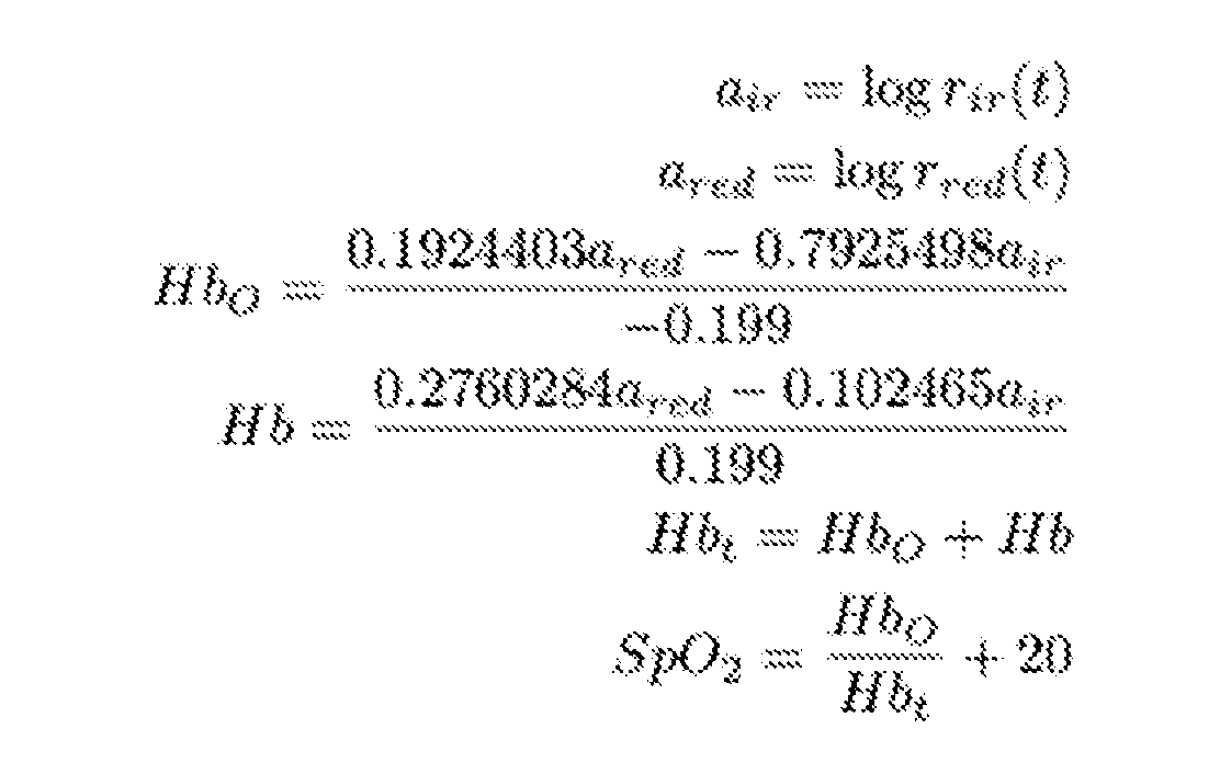
- the blood oxygen value for the subject can be calculated according to a blood oxygen calculation step using the response values for S RED and S IR values.
- the processor 104 is configured to use the S RED and S IR values to calculate a blood oxygen saturation level.
- the processor 104 is configured by a blood oxygen module 324 to access the raw AC extracted values for S RED and S IR and calculate the blood oxygen level for a subject according to:
- the generated biometric parameters for the patient can be output by the processor 104 configured by the output module 314 to output the generated biometric parameters to an output or display device for further use.
- both the glucose value and the biometric parameters are output to a remote database, such as database 108 for further processing and analysis.
- the glucose and biometric parameters are output to a display device 1 10, such as a smartphone or other device for display to a user.
- the output module 314 configures the processor 104 to output the glucose and biometric parameters to the associated or integrated display, as shown in FIG. 6.
- the illuminant 106A and illuminant 106B, the light measurement device 103, processor 104 and an integrated display device are incorporated into single form factor.
- the form factor is a watch or other wearable device configured to rest upon the skin of the subject 102 and provide periodic or continuous monitoring of the glucose and other biometric parameters.
- the processor 104 is configured with an alert module 322, or submodules thereof. The alert module 322 configures the processor 104 to periodically obtain glucose values and biometric parameters of the subject 102 and compare the derived values to one or more pre -determined values or thresholds.
- an alert message is generated.
- an audible alarm or alert is generated by audio device connected to the processor 104.
- the speakers are sent an alert signal or sound to alert the subject 102 that the threshold has been exceeded.
- the alert module is configured to communicate with one or more remote databases or computers 1 12.
- the remote computers 112 or monitors are provided by a health care provider.
- alerts can be generated and sent to one or more additional computers.
- the biometric parameter measurement system described can be configured to alert a parent or guardian, school official or on-site medical care professional that the subject’s biometric parameters have exceed a preset threshold.
Landscapes
- Health & Medical Sciences (AREA)
- Life Sciences & Earth Sciences (AREA)
- Physics & Mathematics (AREA)
- Medical Informatics (AREA)
- Surgery (AREA)
- Biophysics (AREA)
- Pathology (AREA)
- Engineering & Computer Science (AREA)
- Biomedical Technology (AREA)
- Heart & Thoracic Surgery (AREA)
- Veterinary Medicine (AREA)
- Molecular Biology (AREA)
- Public Health (AREA)
- Animal Behavior & Ethology (AREA)
- General Health & Medical Sciences (AREA)
- Cardiology (AREA)
- Optics & Photonics (AREA)
- Physiology (AREA)
- Spectroscopy & Molecular Physics (AREA)
- Emergency Medicine (AREA)
- Hematology (AREA)
- Measurement Of The Respiration, Hearing Ability, Form, And Blood Characteristics Of Living Organisms (AREA)
Abstract
Description


Claims


Priority Applications (4)
| Application Number | Priority Date | Filing Date | Title |
|---|---|---|---|
| JP2023527301A JP2023548388A (en) | 2020-10-28 | 2021-10-28 | Biological parameter measurement |
| EP21887537.5A EP4236796A1 (en) | 2020-10-28 | 2021-10-28 | Biometric parameter measurement |
| US18/251,090 US20230397847A1 (en) | 2020-10-28 | 2021-10-28 | Biometric parameter measurement |
| CA3196697A CA3196697A1 (en) | 2020-10-28 | 2021-10-28 | Biometric parameter measurement |
Applications Claiming Priority (2)
| Application Number | Priority Date | Filing Date | Title |
|---|---|---|---|
| US202063106582P | 2020-10-28 | 2020-10-28 | |
| US63/106,582 | 2020-10-28 |
Publications (1)
| Publication Number | Publication Date |
|---|---|
| WO2022094112A1 true WO2022094112A1 (en) | 2022-05-05 |
Family
ID=81384300
Family Applications (1)
| Application Number | Title | Priority Date | Filing Date |
|---|---|---|---|
| PCT/US2021/057093 WO2022094112A1 (en) | 2020-10-28 | 2021-10-28 | Biometric parameter measurement |
Country Status (5)
| Country | Link |
|---|---|
| US (1) | US20230397847A1 (en) |
| EP (1) | EP4236796A1 (en) |
| JP (1) | JP2023548388A (en) |
| CA (1) | CA3196697A1 (en) |
| WO (1) | WO2022094112A1 (en) |
Citations (6)
| Publication number | Priority date | Publication date | Assignee | Title |
|---|---|---|---|---|
| US20040068163A1 (en) * | 2001-01-26 | 2004-04-08 | Ruchti Timothy L. | Noninvasive measurement of glucose through the optical properties of tissue |
| US20080119701A1 (en) * | 2006-11-03 | 2008-05-22 | Cardiospectra, Inc. | Analyte sensor method and apparatus |
| US20110230744A1 (en) * | 2008-11-07 | 2011-09-22 | Sabirmedical, S.L. | System and apparatus for the non-invasive measurement of glucose levels in blood |
| US20130066172A1 (en) * | 2010-06-22 | 2013-03-14 | Senspec Gmbh | Device and Method for Detecting and Monitoring Ingredients or Properties of a Measurement Medium, In Particular of Physiological Blood Values |
| US20180317821A1 (en) * | 2015-10-05 | 2018-11-08 | Dia-Vit Ltd | Device For Non-Invasive Measurement Of Blood Sugar Level |
| US20190133471A1 (en) * | 2016-04-25 | 2019-05-09 | Performance Athlytics | Method and device for tissue monitoring and heart rate detection |
-
2021
- 2021-10-28 WO PCT/US2021/057093 patent/WO2022094112A1/en active Application Filing
- 2021-10-28 EP EP21887537.5A patent/EP4236796A1/en active Pending
- 2021-10-28 JP JP2023527301A patent/JP2023548388A/en active Pending
- 2021-10-28 US US18/251,090 patent/US20230397847A1/en active Pending
- 2021-10-28 CA CA3196697A patent/CA3196697A1/en active Pending
Patent Citations (6)
| Publication number | Priority date | Publication date | Assignee | Title |
|---|---|---|---|---|
| US20040068163A1 (en) * | 2001-01-26 | 2004-04-08 | Ruchti Timothy L. | Noninvasive measurement of glucose through the optical properties of tissue |
| US20080119701A1 (en) * | 2006-11-03 | 2008-05-22 | Cardiospectra, Inc. | Analyte sensor method and apparatus |
| US20110230744A1 (en) * | 2008-11-07 | 2011-09-22 | Sabirmedical, S.L. | System and apparatus for the non-invasive measurement of glucose levels in blood |
| US20130066172A1 (en) * | 2010-06-22 | 2013-03-14 | Senspec Gmbh | Device and Method for Detecting and Monitoring Ingredients or Properties of a Measurement Medium, In Particular of Physiological Blood Values |
| US20180317821A1 (en) * | 2015-10-05 | 2018-11-08 | Dia-Vit Ltd | Device For Non-Invasive Measurement Of Blood Sugar Level |
| US20190133471A1 (en) * | 2016-04-25 | 2019-05-09 | Performance Athlytics | Method and device for tissue monitoring and heart rate detection |
Also Published As
| Publication number | Publication date |
|---|---|
| JP2023548388A (en) | 2023-11-16 |
| CA3196697A1 (en) | 2022-05-05 |
| US20230397847A1 (en) | 2023-12-14 |
| EP4236796A1 (en) | 2023-09-06 |
Similar Documents
| Publication | Publication Date | Title |
|---|---|---|
| US20220296176A1 (en) | Processing biological data | |
| Sanyal et al. | Algorithms for monitoring heart rate and respiratory rate from the video of a user’s face | |
| AU2017315334B2 (en) | Multispectral mobile tissue assessment | |
| EP2967378B1 (en) | Device and method for determining vital signs of a subject | |
| EP4225136A1 (en) | Personal healthcare device | |
| US9538927B2 (en) | Optical measurement device and a method for an optical measurement | |
| EP3383267A1 (en) | Systems and methods for non-invasive respiratory rate measurement | |
| US10980423B2 (en) | Devices and methods for predicting hemoglobin levels using electronic devices such as mobile phones | |
| FR2834628A1 (en) | PATIENT MONITORING APPARATUS AND METHOD WITH NON-INVASIVE CARDIAC FLOW MONITORING | |
| Ženko et al. | Pulse rate variability and blood oxidation content identification using miniature wearable wrist device | |
| US11701027B2 (en) | Optical respiration rate detection device | |
| Ayesha et al. | Heart rate monitoring using PPG with smartphone camera | |
| CN111698943A (en) | Systems and methods for non-invasively monitoring hematocrit concentration | |
| WO2020160058A1 (en) | Systems and methods for computationally efficient non-invasive blood quality measurement | |
| US20230397847A1 (en) | Biometric parameter measurement | |
| US11464453B2 (en) | Cellphone based tissue oxygenation measuring device | |
| WO2018211519A1 (en) | Wireless portable vitals and fitness tracker | |
| WO2019215181A1 (en) | Apparatus and method and computer program product for determining a blood pressure measurement | |
| CN110197186B (en) | PPG-based illumination comfort level measurement method and system | |
| Anagha et al. | A Better Digital Filtering Technique for Estimation of SPO 2 and Heart Rate from PPG Signals | |
| EP2848194B1 (en) | Method, system and apparatus for generating pulse estimate | |
| Popescu et al. | Cardiowatch: A solution for monitoring the heart rate on a Mobile device | |
| KR20220045340A (en) | Apparatus and method for estimating target component | |
| Hernandez Guzman | Cardiac Inter Beat Interval and Atrial Fibrillation Detection using Video Plethysmography | |
| Alić et al. | Non-contact video-based heart rate and heart rate variability extraction from different body regions |
Legal Events
| Date | Code | Title | Description |
|---|---|---|---|
| 121 | Ep: the epo has been informed by wipo that ep was designated in this application |
Ref document number: 21887537 Country of ref document: EP Kind code of ref document: A1 |
|
| ENP | Entry into the national phase |
Ref document number: 3196697 Country of ref document: CA |
|
| WWE | Wipo information: entry into national phase |
Ref document number: 2023527301 Country of ref document: JP |
|
| NENP | Non-entry into the national phase |
Ref country code: DE |
|
| ENP | Entry into the national phase |
Ref document number: 2021887537 Country of ref document: EP Effective date: 20230530 |