WO2022092224A1 - Connector - Google Patents
Connector Download PDFInfo
- Publication number
- WO2022092224A1 WO2022092224A1 PCT/JP2021/039871 JP2021039871W WO2022092224A1 WO 2022092224 A1 WO2022092224 A1 WO 2022092224A1 JP 2021039871 W JP2021039871 W JP 2021039871W WO 2022092224 A1 WO2022092224 A1 WO 2022092224A1
- Authority
- WO
- WIPO (PCT)
- Prior art keywords
- shell
- terminal
- connector
- contact
- pair
- Prior art date
Links
- 238000005452 bending Methods 0.000 claims description 13
- 238000006073 displacement reaction Methods 0.000 claims description 8
- 239000000463 material Substances 0.000 claims description 6
- 230000005540 biological transmission Effects 0.000 abstract description 21
- 239000004020 conductor Substances 0.000 description 106
- 239000000758 substrate Substances 0.000 description 17
- 239000002184 metal Substances 0.000 description 10
- 230000002093 peripheral effect Effects 0.000 description 8
- 238000000034 method Methods 0.000 description 7
- 230000033228 biological regulation Effects 0.000 description 5
- 230000008569 process Effects 0.000 description 5
- 230000001105 regulatory effect Effects 0.000 description 4
- 238000013459 approach Methods 0.000 description 3
- 230000015572 biosynthetic process Effects 0.000 description 3
- 238000012790 confirmation Methods 0.000 description 3
- 239000012212 insulator Substances 0.000 description 3
- 229920003002 synthetic resin Polymers 0.000 description 3
- 239000000057 synthetic resin Substances 0.000 description 3
- 230000009471 action Effects 0.000 description 2
- 239000000853 adhesive Substances 0.000 description 2
- 230000001070 adhesive effect Effects 0.000 description 2
- 230000007423 decrease Effects 0.000 description 2
- 230000000694 effects Effects 0.000 description 2
- 230000006872 improvement Effects 0.000 description 2
- 230000008859 change Effects 0.000 description 1
- 238000006243 chemical reaction Methods 0.000 description 1
- 230000005484 gravity Effects 0.000 description 1
- 238000003466 welding Methods 0.000 description 1
Images


Classifications
-
- H—ELECTRICITY
- H01—ELECTRIC ELEMENTS
- H01R—ELECTRICALLY-CONDUCTIVE CONNECTIONS; STRUCTURAL ASSOCIATIONS OF A PLURALITY OF MUTUALLY-INSULATED ELECTRICAL CONNECTING ELEMENTS; COUPLING DEVICES; CURRENT COLLECTORS
- H01R24/00—Two-part coupling devices, or either of their cooperating parts, characterised by their overall structure
- H01R24/38—Two-part coupling devices, or either of their cooperating parts, characterised by their overall structure having concentrically or coaxially arranged contacts
- H01R24/40—Two-part coupling devices, or either of their cooperating parts, characterised by their overall structure having concentrically or coaxially arranged contacts specially adapted for high frequency
-
- H—ELECTRICITY
- H01—ELECTRIC ELEMENTS
- H01R—ELECTRICALLY-CONDUCTIVE CONNECTIONS; STRUCTURAL ASSOCIATIONS OF A PLURALITY OF MUTUALLY-INSULATED ELECTRICAL CONNECTING ELEMENTS; COUPLING DEVICES; CURRENT COLLECTORS
- H01R12/00—Structural associations of a plurality of mutually-insulated electrical connecting elements, specially adapted for printed circuits, e.g. printed circuit boards [PCB], flat or ribbon cables, or like generally planar structures, e.g. terminal strips, terminal blocks; Coupling devices specially adapted for printed circuits, flat or ribbon cables, or like generally planar structures; Terminals specially adapted for contact with, or insertion into, printed circuits, flat or ribbon cables, or like generally planar structures
- H01R12/70—Coupling devices
- H01R12/91—Coupling devices allowing relative movement between coupling parts, e.g. floating or self aligning
-
- H—ELECTRICITY
- H01—ELECTRIC ELEMENTS
- H01R—ELECTRICALLY-CONDUCTIVE CONNECTIONS; STRUCTURAL ASSOCIATIONS OF A PLURALITY OF MUTUALLY-INSULATED ELECTRICAL CONNECTING ELEMENTS; COUPLING DEVICES; CURRENT COLLECTORS
- H01R13/00—Details of coupling devices of the kinds covered by groups H01R12/70 or H01R24/00 - H01R33/00
- H01R13/02—Contact members
- H01R13/22—Contacts for co-operating by abutting
- H01R13/24—Contacts for co-operating by abutting resilient; resiliently-mounted
- H01R13/2407—Contacts for co-operating by abutting resilient; resiliently-mounted characterized by the resilient means
-
- H—ELECTRICITY
- H01—ELECTRIC ELEMENTS
- H01R—ELECTRICALLY-CONDUCTIVE CONNECTIONS; STRUCTURAL ASSOCIATIONS OF A PLURALITY OF MUTUALLY-INSULATED ELECTRICAL CONNECTING ELEMENTS; COUPLING DEVICES; CURRENT COLLECTORS
- H01R13/00—Details of coupling devices of the kinds covered by groups H01R12/70 or H01R24/00 - H01R33/00
- H01R13/46—Bases; Cases
- H01R13/502—Bases; Cases composed of different pieces
-
- H—ELECTRICITY
- H01—ELECTRIC ELEMENTS
- H01R—ELECTRICALLY-CONDUCTIVE CONNECTIONS; STRUCTURAL ASSOCIATIONS OF A PLURALITY OF MUTUALLY-INSULATED ELECTRICAL CONNECTING ELEMENTS; COUPLING DEVICES; CURRENT COLLECTORS
- H01R13/00—Details of coupling devices of the kinds covered by groups H01R12/70 or H01R24/00 - H01R33/00
- H01R13/648—Protective earth or shield arrangements on coupling devices, e.g. anti-static shielding
- H01R13/658—High frequency shielding arrangements, e.g. against EMI [Electro-Magnetic Interference] or EMP [Electro-Magnetic Pulse]
- H01R13/6581—Shield structure
- H01R13/6582—Shield structure with resilient means for engaging mating connector
-
- H—ELECTRICITY
- H01—ELECTRIC ELEMENTS
- H01R—ELECTRICALLY-CONDUCTIVE CONNECTIONS; STRUCTURAL ASSOCIATIONS OF A PLURALITY OF MUTUALLY-INSULATED ELECTRICAL CONNECTING ELEMENTS; COUPLING DEVICES; CURRENT COLLECTORS
- H01R13/00—Details of coupling devices of the kinds covered by groups H01R12/70 or H01R24/00 - H01R33/00
- H01R13/648—Protective earth or shield arrangements on coupling devices, e.g. anti-static shielding
- H01R13/658—High frequency shielding arrangements, e.g. against EMI [Electro-Magnetic Interference] or EMP [Electro-Magnetic Pulse]
- H01R13/6591—Specific features or arrangements of connection of shield to conductive members
- H01R13/6597—Specific features or arrangements of connection of shield to conductive members the conductive member being a contact of the connector
-
- H—ELECTRICITY
- H01—ELECTRIC ELEMENTS
- H01R—ELECTRICALLY-CONDUCTIVE CONNECTIONS; STRUCTURAL ASSOCIATIONS OF A PLURALITY OF MUTUALLY-INSULATED ELECTRICAL CONNECTING ELEMENTS; COUPLING DEVICES; CURRENT COLLECTORS
- H01R24/00—Two-part coupling devices, or either of their cooperating parts, characterised by their overall structure
- H01R24/38—Two-part coupling devices, or either of their cooperating parts, characterised by their overall structure having concentrically or coaxially arranged contacts
- H01R24/40—Two-part coupling devices, or either of their cooperating parts, characterised by their overall structure having concentrically or coaxially arranged contacts specially adapted for high frequency
- H01R24/50—Two-part coupling devices, or either of their cooperating parts, characterised by their overall structure having concentrically or coaxially arranged contacts specially adapted for high frequency mounted on a PCB [Printed Circuit Board]
-
- H—ELECTRICITY
- H01—ELECTRIC ELEMENTS
- H01R—ELECTRICALLY-CONDUCTIVE CONNECTIONS; STRUCTURAL ASSOCIATIONS OF A PLURALITY OF MUTUALLY-INSULATED ELECTRICAL CONNECTING ELEMENTS; COUPLING DEVICES; CURRENT COLLECTORS
- H01R12/00—Structural associations of a plurality of mutually-insulated electrical connecting elements, specially adapted for printed circuits, e.g. printed circuit boards [PCB], flat or ribbon cables, or like generally planar structures, e.g. terminal strips, terminal blocks; Coupling devices specially adapted for printed circuits, flat or ribbon cables, or like generally planar structures; Terminals specially adapted for contact with, or insertion into, printed circuits, flat or ribbon cables, or like generally planar structures
- H01R12/70—Coupling devices
- H01R12/71—Coupling devices for rigid printing circuits or like structures
- H01R12/712—Coupling devices for rigid printing circuits or like structures co-operating with the surface of the printed circuit or with a coupling device exclusively provided on the surface of the printed circuit
- H01R12/716—Coupling device provided on the PCB
-
- H—ELECTRICITY
- H01—ELECTRIC ELEMENTS
- H01R—ELECTRICALLY-CONDUCTIVE CONNECTIONS; STRUCTURAL ASSOCIATIONS OF A PLURALITY OF MUTUALLY-INSULATED ELECTRICAL CONNECTING ELEMENTS; COUPLING DEVICES; CURRENT COLLECTORS
- H01R13/00—Details of coupling devices of the kinds covered by groups H01R12/70 or H01R24/00 - H01R33/00
- H01R13/02—Contact members
- H01R13/22—Contacts for co-operating by abutting
- H01R13/24—Contacts for co-operating by abutting resilient; resiliently-mounted
- H01R13/2442—Contacts for co-operating by abutting resilient; resiliently-mounted with a single cantilevered beam
-
- H—ELECTRICITY
- H01—ELECTRIC ELEMENTS
- H01R—ELECTRICALLY-CONDUCTIVE CONNECTIONS; STRUCTURAL ASSOCIATIONS OF A PLURALITY OF MUTUALLY-INSULATED ELECTRICAL CONNECTING ELEMENTS; COUPLING DEVICES; CURRENT COLLECTORS
- H01R2103/00—Two poles
-
- H—ELECTRICITY
- H01—ELECTRIC ELEMENTS
- H01R—ELECTRICALLY-CONDUCTIVE CONNECTIONS; STRUCTURAL ASSOCIATIONS OF A PLURALITY OF MUTUALLY-INSULATED ELECTRICAL CONNECTING ELEMENTS; COUPLING DEVICES; CURRENT COLLECTORS
- H01R2201/00—Connectors or connections adapted for particular applications
-
- H—ELECTRICITY
- H01—ELECTRIC ELEMENTS
- H01R—ELECTRICALLY-CONDUCTIVE CONNECTIONS; STRUCTURAL ASSOCIATIONS OF A PLURALITY OF MUTUALLY-INSULATED ELECTRICAL CONNECTING ELEMENTS; COUPLING DEVICES; CURRENT COLLECTORS
- H01R2201/00—Connectors or connections adapted for particular applications
- H01R2201/26—Connectors or connections adapted for particular applications for vehicles
Definitions
- This disclosure relates to connection structures and connectors.
- connection structure and connector disclosed in Patent Document 1 are known.
- the first connection terminal of the first case member and the second connection terminal of the connector mounted on the circuit board are in conduction contact with each other.
- this connection structure even if the relative position between the circuit board and the first case member is slightly deviated from the normal position, it is possible to obtain a state of conduction contact.
- One object of the present disclosure is to provide a connection structure and a connector having an excellent high-speed transmission performance while having a function for dealing with misalignment.
- the X direction, the Y direction, and the Z direction which are direction concepts based on the object and are perpendicular to each other, are used.
- connection structure is a connection structure including a connection object and a connector that contacts the connection object from one side in the Z direction and the other side in the Z direction from the other side in the Z direction.
- the object to be connected includes an inner conductor portion and an outer conductor portion surrounding the inner conductor portion, and the connector includes a signal terminal having a first connector contact portion and a shield member having a second connector contact portion.
- the inner conductor portion has an inner conductor contact portion that can be butted in the Z direction with respect to the first connector contact portion
- the outer conductor portion has an inner conductor contact portion with respect to the second connector contact portion. It has an outer conductor contact portion that can be butted in the Z direction.
- connection structure is a connection structure between the object to be connected and the connector.
- the connector includes a signal terminal having a first connector contact portion, a shield member having a second connector contact portion, and a housing, and is connected to the object to be connected on one side in the Z direction and the other side in the Z direction on the other side in the Z direction.
- the object to be connected includes an inner conductor portion and an outer conductor portion. The inner conductor contact portion of the inner conductor portion contacts the first connector contact portion of the connector, and the outer conductor portion contact portion of the outer conductor portion contacts the second connector contact portion of the connector.
- the outer conductor portion surrounds the inner conductor portion.
- the outer conductor portion shields the inner conductor portion, so that the high-speed transmission performance is improved.
- the inner conductor contact portion can be butted against the first connector contact portion in the Z direction
- the outer conductor contact portion can be butted against the second connector contact portion in the Z direction.
- connection structure according to the second aspect is a plane in which the inner conductor contact portion and the outer conductor contact portion both have the other side in the Z direction as the normal direction, and the position in the Z direction is Match.
- the inner conductor contact portion and the outer conductor contact portion are both planes having the other side in the Z direction as the normal direction, and their positions in the Z direction coincide with each other. Therefore, in the direction orthogonal to the Z direction, which is the butt direction, it is possible to more smoothly respond to the relative positional deviation between the object to be connected and the connector.
- the inner conductor portion and the outer conductor portion form a coaxial connector portion.
- the coaxial connector portion formed by the inner conductor portion and the outer conductor portion, and the first connector contact portion and the second connector contact portion of the connector are in butt contact with each other.
- connection structure according to the fourth aspect in any one of the first to third aspects, the second connector contact portion and the outer conductor portion are in contact with each other on one side in the Z direction with respect to the housing.
- a recess is formed in the housing. Then, in the recess of the housing, the second connector contact portion and the outer conductor portion come into contact with each other. That is, the second connector contact portion and the outer conductor portion are in contact with each other inside the housing in the Z direction. Therefore, it is necessary to form the housing in a large size in the direction orthogonal to the Z direction so that a concave portion into which the outer conductor portion of the object to be connected can enter can be formed.
- the housing since it is not necessary to form a recess in the housing into which the outer conductor portion of the object to be connected can enter, the housing can be miniaturized in the direction orthogonal to the Z direction.
- the connection structure can be miniaturized.
- the first connector contact portion and the inner conductor portion may be further configured to be in contact with each other on one side in the Z direction with respect to the housing.
- connection structure according to the fifth aspect has the shield member having a top surface portion facing the outer conductor contact portion in the Z direction and located on one side of the housing in the Z direction.
- the top surface portion has the second connector contact portion.
- the shield member has a top surface portion located on one side in the Z direction of the housing, and the top surface portion has a second connector contact portion, so that the outer conductor portion contacts the outer conductor portion on one side in the Z direction with respect to the housing. Two connector contact parts are realized.
- the shield member has a shell, and the shell faces the outer conductor contact portion in the Z direction and is on one side of the housing in the Z direction. It has a top surface portion located and a side surface portion that surrounds the signal terminal from a direction orthogonal to the Z direction, and the top surface portion has the second connector contact portion.
- the shield member since the shield member has a shell and the side surface portion of the shell surrounds the signal terminal from the direction orthogonal to the Z direction, noise countermeasures are taken on the connector side in the connection structure. Further, since the top surface portion of the shell is located on one side in the Z direction of the housing and has the second connector contact portion, the second connector contact portion that contacts the outer conductor portion on one side in the Z direction with respect to the housing is realized. ..
- the shield member has a shell having the second connector contact portion, and the shell has a plate thickness direction in the Z direction.
- the shell has a top surface portion and a side surface portion extending from the outer edge of the top surface portion to the other side in the Z direction, and the shell is arranged so as to cover the housing from one side in the Z direction. Is formed with an opening that exposes the first connector contact portion, and a region of the upper surface of the top surface portion that surrounds the opening contacts the outer conductor contact portion as the second connector contact portion.
- the second connector contact portion of the connector needs to be in contact with the outer conductor contact portion, and in order to realize this, the connector may be enlarged in the X direction and the Y direction.
- a concave portion is formed in the housing of the connector, and a second connector contact portion (tip portion of the recess ground pin) is arranged in the concave portion. Therefore, it is necessary to form a recess of the housing so that the outer conductor portion of the object to be connected enters, and the housing becomes large in the X direction and the Y direction, and as a result, the connector becomes large.
- the connector has a shell having a top surface portion and a side surface portion, and the shell is arranged so as to cover the housing from one side in the Z direction. Then, one surface of the top surface portion of the shell in the Z direction functions as a second connector contact portion. Therefore, it is not necessary to form a recess in the housing into which the outer conductor portion of the object to be connected enters, and a wide area on one side in the Z direction of the connector can function as the second connector contact portion. As a result, the connector can be miniaturized in the X direction and the Y direction.
- the housing has a pair of terminal proximity walls facing in the Y direction, and the said housing is between the pair of terminal proximity walls.
- a signal terminal is arranged, the shield member has a pair of auxiliary plates, and the pair of auxiliary plates are arranged outward in the Y direction with respect to the pair of terminal proximity walls while the plate thickness direction is directed in the Y direction. Will be done.
- the housing has a pair of terminal proximity walls facing in the Y direction
- the shield member has a pair of auxiliary plates.
- the signal terminals are arranged between a pair of terminal proximity walls.
- the pair of auxiliary plates are arranged in the Y direction with respect to the pair of terminal proximity walls while the plate thickness direction is directed to the Y direction.
- a part of the housing is arranged so as to be adjacent to the signal terminal in the Y direction, and an auxiliary plate is arranged on the outside thereof. Therefore, the impedance of the signal terminal is adjusted to make the connector suitable for high-speed transmission. can.
- the signal terminal has a held portion held between the pair of terminal proximity walls, and the held portion of the pair of terminal proximity walls is held.
- the outer surface in the Y direction is expanded outward in the Y direction more than the other portions, and the pair of auxiliary plates are shaped along the outer surface in the Y direction of the pair of terminal proximity walls.
- the held portion of the signal terminal is held between the pair of terminal proximity walls.
- the surface on the outer side in the Y direction is expanded to the outer side in the Y direction as compared with the other portions.
- the pair of auxiliary plates has a shape along the outer surface of the pair of terminal proximity walls in the Y direction. Therefore, since the distance between the signal terminal and the holding plate in the Y direction approaches a constant regardless of the position in the X direction, the impedance is adjusted and the transmission performance is improved.
- the shield member has a shell having the second connector contact portion and a ground having a shell contact portion that is in conduction contact with the shell.
- the signal terminal is provided with a terminal, and the signal terminal extends in a predetermined direction when viewed from the Z direction, and has a tip-side extension portion having the first connector contact portion on the tip-end side in the extension direction, and the ground terminal is a ground terminal.
- the pair of tip-side extension portions having the shell contact portion on the tip end side in the extension direction while extending in the predetermined direction when viewed from the Z direction, and the pair of tip-side extension portions of the ground terminal are the signals. It is arranged on both sides in the Y direction with respect to the extension portion on the tip side of the terminal.
- the signal terminal has a tip end side extension portion having a first connector contact portion on the extension direction tip side
- the ground terminal has a pair of tip side having a shell contact portion in contact with the shell on the extension direction tip side. It has an extension.
- both the tip-side extension portion of the signal terminal and the pair of tip-side extension portions of the ground terminal extend in the same predetermined direction when viewed from the Z direction.
- the pair of tip side extension portions of the ground terminal are arranged on both sides in the Y direction with respect to the tip end side extension portion of the signal terminal. Therefore, one tip-side extension portion of the ground terminal, the tip-side extension portion of the signal terminal, and the other tip-side extension portion of the ground terminal function as a GSG structure (ground-signal-ground structure), and the transmission characteristics are improved. Will be improved.
- connection object in any one of the first to tenth aspects, is a rear member forming a part of the outer shell of the camera module, and the rear member is the rear member. It is a connector portion having an inner conductor portion and the outer conductor portion, and includes the connector portion that electrically connects the inside and the outside of the camera module.
- connection structure is a connection structure between the rear member of the camera module and the connector.
- the connector according to the first aspect includes a signal terminal having a terminal contact portion capable of conducting conduction contact with a first contact portion of a connection object connected from one side in the Z direction, a housing holding the signal terminal, and the signal.
- a connector comprising a shell that encloses at least a portion of a terminal, wherein the shell has a shielded contact that is conductively contactable with a second contact of the object to be connected, the shell being in the Z direction. It can be displaced.
- the connector comprises a signal terminal, a housing that holds the signal terminal, and a shell that surrounds at least a portion of the signal terminal.
- the signal terminal has a terminal contact portion capable of conducting conductive contact with the first contact portion of the object to be connected connected from one side in the Z direction
- the shell has a shield contact capable of conducting conduction contact with the second contact portion of the object to be connected.
- the shell having the shield contact portion can be displaced in the Z direction. Therefore, it is possible to absorb the positional deviation (for example, the deviation due to the assembly tolerance) between the connector and the object to be connected in the Z direction.
- the shell has a top surface portion located on one side in the Z direction of the housing, and the terminal contact portion is exposed in the center of the top surface portion. An opening is formed.
- the shell has a top surface portion located on one side of the housing in the Z direction.
- An opening is formed in the center of the top surface to expose the terminal contact portion. Therefore, the region of the upper surface of the top surface portion surrounding the opening can function as the shield contact portion.
- the connector according to the third aspect has a side surface portion that surrounds the signal terminal from a direction orthogonal to the Z direction.
- the shell has a side surface portion.
- the side surface portion surrounds the signal terminal from the direction orthogonal to the Z direction. Therefore, noise countermeasures are improved.
- the connector according to the fourth aspect has a shape in which the side surface portion thereof is bent so as to surround the signal terminal from a direction orthogonal to the Z direction. A portion where the plate members are overlapped with each other is formed so as not to create a gap in the shape surrounding the terminals from the direction orthogonal to the Z direction.
- the side surface portion is formed into a shape that surrounds the signal terminal from the direction orthogonal to the Z direction by bending the plate material.
- a portion where the plate materials are overlapped with each other is formed so as not to create a gap in the shape surrounding the signal terminal from the direction orthogonal to the Z direction. Therefore, noise countermeasures for signal terminals are improved.
- the connector according to the fifth aspect has a top surface portion arranged on one side in the Z direction of the housing and the signal terminal on the other side in the Z direction from the top surface portion in the Z direction. It has a side surface portion that surrounds the top surface portion from a direction orthogonal to the above, and an opening that exposes the terminal contact portion is formed in the center of the top surface portion, and the side surface portion has the top surface portion and the curved portion, respectively. It is composed of a plurality of plate portions connected via a plurality of plates, and among the plurality of plate portions, adjacent plate portions are superposed on each other.
- the side surface portion of the shell is composed of a plurality of plate portions connected via a top surface portion and a curved portion, respectively.
- adjacent plate portions are superposed on each other. Therefore, it is possible to prevent the formation of a gap between adjacent plate portions among the plurality of plate portions.
- the connector according to the sixth aspect includes an elastic support portion that elastically supports the shell so as to be displaceable in the Z direction.
- the connector includes an elastic support portion that elastically supports the shell so that it can be displaced in the Z direction. Therefore, by displacing the shell to the other side in the Z direction to bring it into a connected state, the shield contact portion can be pressed and contacted with the object to be connected.
- the housing has a pair of terminal proximity walls facing in the Y direction, and the signal is provided between the pair of terminal proximity walls.
- the terminal is arranged, and the connector is provided with a pair of auxiliary plates arranged outside the Y direction with respect to the pair of terminal proximity walls while the plate thickness direction is directed to the Y direction.
- the housing has a pair of terminal proximity walls facing in the Y direction, and signal terminals are arranged between the pair of terminal proximity walls.
- the connector has a pair of auxiliary plates.
- the pair of auxiliary plates are arranged in the Y direction with respect to the pair of terminal proximity walls while the plate thickness direction is directed to the Y direction.
- a part of the housing is arranged so as to be adjacent to the signal terminal in the Y direction, and an auxiliary plate is arranged on the outside thereof. Therefore, the impedance of the signal terminal is adjusted to make the connector suitable for high-speed transmission. can.
- the signal terminal has a held portion held between the pair of terminal proximity walls, and the held portion of the pair of terminal proximity walls is held.
- the outer surface in the Y direction is expanded outward in the Y direction more than the other portions, and the pair of auxiliary plates are shaped along the outer surface in the Y direction of the pair of terminal proximity walls.
- the held portion of the signal terminal is held between the pair of terminal proximity walls.
- the surface on the outer side in the Y direction is expanded to the outer side in the Y direction as compared with the other parts.
- the pair of auxiliary plates has a shape along the outer surface of the pair of terminal proximity walls in the Y direction. Therefore, since the distance between the signal terminal and the holding plate in the Y direction approaches a constant regardless of the position in the X direction, the impedance is adjusted and the transmission performance is improved.
- the connector according to the ninth aspect in any one of the first to eighth aspects, includes a ground terminal for conducting a conductive connection between the attachment object to which the connector is attached and the shell.
- the connector includes a ground terminal for conducting a conductive connection between the mounting object to which the connector is mounted and the shell. Therefore, stable high-speed transmission performance can be ensured as compared with a mode in which the shell is not electrically connected to the object to be mounted.
- the connector according to the tenth aspect is a separate body of the shell and the ground terminal, and the ground terminal has an elastic support portion that elastically supports the shell so as to be displaceable in the Z direction.
- the elastic support portion has a shell contact portion that electrically connects the ground terminal and the shell by conducting conduction contact with the shell.
- the shell and the ground terminal are separate bodies.
- the ground terminal has an elastic support portion that elastically supports the shell so as to be displaceable in the Z direction, and the elastic support portion has a shell contact portion that electrically connects the ground terminal and the shell by conducting conduction contact with the shell. Therefore, both the elastic support of the shell and the conduction connection between the shell and the ground terminal can be performed by the elastic support portion.
- the connector according to the eleventh aspect is integrally with an elastic support portion that elastically supports the shell in the Z direction by contacting the housing. It is formed.
- the elastic support portion integrally formed with the shell is configured to be in contact with the housing, so that the shell is elastically supported so as to be displaceable in the Z direction.
- the connector according to the twelfth aspect is a separate body from the shell and the ground terminal, and the shell is elastic so that the shell can be displaced in the Z direction by coming into contact with the housing.
- the ground terminal has a shell contact that is in conductive contact with the shell.
- the elastic support portion integrally formed with the shell is configured to be in contact with the housing, so that the shell is elastically supported so as to be displaceable in the Z direction. Further, the conduction connection between the ground terminal and the shell is realized by the shell contact portion of the ground terminal making a conduction contact with the shell.
- the signal terminal extends in a predetermined direction when viewed from the Z direction, and has a tip-side extension portion having the terminal contact portion on the tip-end side in the extension direction.
- the ground terminal extends in the predetermined direction when viewed from the Z direction, and has a pair of tip-side extension portions having the shell contact portion on the tip end side in the extension direction, and the pair of tip ends of the ground terminal.
- the side extension portions are arranged on both sides in the Y direction with respect to the tip end side extension portion of the signal terminal.
- the signal terminal has a tip side extension portion having a terminal contact portion on the extension direction tip side
- the ground terminal has a pair of tip side extension having a shell contact portion in contact with the shell on the extension direction tip side.
- both the tip-side extension portion of the signal terminal and the pair of tip-side extension portions of the ground terminal extend in the same predetermined direction when viewed from the Z direction.
- the pair of tip side extension portions of the ground terminal are arranged on both sides in the Y direction with respect to the tip end side extension portion of the signal terminal. Therefore, one tip-side extension portion of the ground terminal, the tip-side extension portion of the signal terminal, and the other tip-side extension portion of the ground terminal function as a GSG structure (ground-signal-ground structure), and the transmission characteristics are improved. Will be improved.
- the direction in which the shield contact portion contacts the second contact portion of the connection target object and the terminal contact portion are the connection target.
- the direction of contact with the first contact portion of the object is the Z direction.
- the direction in which the shield contact portion contacts the second contact portion of the connection target object and the direction in which the terminal contact portion contacts the first contact portion of the connection target object are both in the Z direction. Therefore, the shape of the signal terminal can be simplified as compared with the embodiment in which the contact direction of the terminal contact portion is perpendicular to the Z direction, for example.
- the shield contact portion in any one of the first to the fourteenth aspects, in the initial state, is located on one side in the Z direction with respect to the terminal contact portion.
- the shield contact portion in the initial state, is located on one side in the Z direction with respect to the terminal contact portion. Therefore, when contacting the object to be connected, the shield contact portion tends to come into contact first.
- the connector according to the sixteenth aspect is a pair of movable connectors in which the plate thickness direction is directed in the Y direction and the shell is displaced in the Z direction in conjunction with the displacement in the Z direction.
- An auxiliary plate is further provided, and a portion of the signal terminal projecting from the housing to one side in the Z direction is located between the pair of movable auxiliary plates.
- the connector includes a pair of movable auxiliary plates that are oriented in the Y direction in the plate thickness direction and are displaced in the Z direction in conjunction with the displacement of the shell in the Z direction. Between the pair of movable auxiliary plates, a portion of the signal terminal protruding from the housing to one side in the Z direction is located. Therefore, the impedance of the portion of the signal terminal protruding from the housing to one side in the Z direction is adjusted, and high-speed transmission performance is improved.
- the connector according to the seventeenth aspect has a pair of movable auxiliary plates that are oriented in the Y direction in the plate thickness direction and are displaced in the Z direction in conjunction with the displacement of the shell in the Z direction. Further provided, a portion of the signal terminal protruding from the housing to one side in the Z direction is located between the pair of movable auxiliary plates.
- the impedance of the signal terminal is adjusted by the pair of auxiliary plates and the pair of movable auxiliary plates, and the high-speed transmission performance is further improved.
- it may be further configured such that "the movable auxiliary plate and the auxiliary plate are in conduction contact".
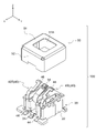
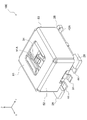
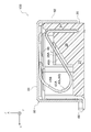
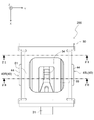
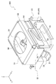
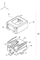
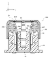
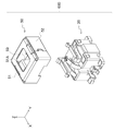
- FIG. 1 It is an exploded perspective view of the connector which concerns on 1st Embodiment. It is a perspective view in the process of assembling the connector which concerns on 1st Embodiment. It is a perspective view of the connector (initial state) which concerns on 1st Embodiment. It is a perspective view of the connector (the state where the shell is greatly displaced) which concerns on 1st Embodiment. It is sectional drawing corresponding to FIG. It is sectional drawing corresponding to FIG. It is sectional drawing corresponding to FIG. It is sectional drawing corresponding to FIG. It is a perspective view of a housing. It is a perspective view of a signal terminal. It is a perspective view of a ground terminal. It is a perspective view seen from the bottom of the shell.
- the ⁇ X direction may be described as the front-back direction, the ⁇ Y direction as the width direction, and the ⁇ Z direction as the vertical direction.
- FIG. 12 is an exploded sectional view of the camera module 1 according to the present embodiment.
- the connector 100 is a connector for electrically connecting the substrate 71 as the "mounting object” and the rear member 80 as the "connecting object”.
- the connector 100 according to the first embodiment will be described, and then the camera module 1 provided with the connector 100 will be described. Then, another embodiment will be described.
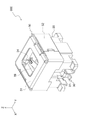
- FIG. 1 is an exploded perspective view of the connector 100.
- the connector 100 includes a housing 20, a signal terminal 30, two ground terminals 40L and 40R, and a shell 50.
- the connector 100 is assembled by the following procedure (FIGS. 1 to 3). First, the signal terminal 30 and the ground terminal 40 are attached to the housing 20. Specifically, the signal terminal 30 is press-fitted into the housing 20 from the + X direction, and the pair of ground terminals 40 are press-fitted from the + Z direction. Then, the shell 50 is attached to the housing 20 to which the signal terminal 30 and the ground terminal 40 are attached from the + Z direction.
- FIG. 8 is a perspective view of the housing 20.
- the material constituting the housing 20 is an insulator such as synthetic resin.
- the housing 20 has a bottom wall 21, a pair of side walls 22, and a rear wall 23. Further, the housing 20 has a pair of terminal proximity walls 24. The pair of terminal proximity walls 24 are close to the left and right of the signal terminal 30. The pair of terminal proximity walls 24 are connected in the width direction by the connecting wall 27 at the rear and the upper part.
- the pair of terminal proximity walls 24 are formed inside the pair of side walls 22 in the width direction with the wall thickness direction facing the width direction.
- a signal terminal 30 is arranged between the pair of terminal proximity walls 24.
- the held portion 32 of the signal terminal 30 is press-fitted to the lower end of the front portion 24A of the pair of terminal proximity walls 24.
- the housing 20 has a bulging portion 26 that bulges upward with respect to the bottom wall 21.
- the bulging portion 26 is formed at the rear portion between the side wall 22 and the terminal proximity wall 24.
- the bulging portion 26 has an inclined surface 26A.
- the inclined surface 26A is inclined so as to be substantially parallel to the first extension portion 45A of the elastic portion 45 when the ground terminal 40 is greatly deformed (see FIG. 7). As a result, the strength of the housing 20 is improved by the bulging portion 26 while preventing the deformation of the ground terminal 40 from being hindered.
- the housing 20 has a ground terminal holding portion 25 for holding the ground terminal 40.
- a pair of ground terminal holding portions 25 are formed on the outside of the pair of terminal proximity walls 24.
- the ground terminal holding portion 25 is formed as a wall connecting the bulging portion 26 and the rear portion 24B of the terminal proximity wall 24 in the width direction.
- the housing 20 has an upper regulating unit 22A that regulates the movement of the shell 50 in the + Z direction.
- the upper regulating portion 22A is a protrusion formed on the outer side in the width direction of the pair of side walls 22.
- the upper regulating portion 22A is located at the upper end of the side wall 22.
- the upper regulation portion 22A is formed at two locations on each side wall 22 at a total of four locations.
- the housing 20 has a guide portion 22B that guides the vertical movement of the shell 50.
- the guide portion 22B bulges outward in the width direction from each of the pair of side walls 22.
- the guide portion 22B extends in the vertical direction. In the vicinity of the upper end of the guide portion 22B, the width dimension decreases upward and the amount of bulging outward in the width direction also decreases upward.
- the lower end of the guide portion 22B coincides with the lower end of the side wall 22 in the vertical direction.
- the housing 20 has a tail protection portion 28.
- tail protection portions 28 are formed corresponding to the corner portions of the substantially quadrangular housing 20 in a plan view.
- the tail protection portion 28 protects the tails (connection portion 31, connection portions 42A, 44) of the signal terminal 30 and the ground terminal 40 (see FIG. 3).
- a groove portion 21A recessed on the lower side is formed corresponding to the position where the first vertical plate portion 41 of the ground terminal 40 is arranged.
- FIG. 9 is a perspective view of the signal terminal 30.
- the signal terminal 30 has a connection portion 31 connected to a substrate 71 (see FIG. 12) as an “object to be mounted”, a held portion 32 held by the housing 20, and a contact portion 34 described later in a substantially vertical direction.
- An elastic portion 33 that elastically supports the displacement and a contact portion 34 that contacts the central conductor contact portion 83A of the rear member 80 as a “connection object” are integrally provided in this order.
- connection portion 31 faces the plate thickness direction in the vertical direction.
- the held portion 32 faces the plate thickness direction in the vertical direction.
- Protrusions to be press-fitted into the housing 20 are formed on both sides of the held portion 32 in the width direction.
- the width dimension of the held portion 32 (the width dimension of the portion excluding the protrusion) is larger than the width dimension of the elastic portion 33.
- the elastic portion 33 has a first extension portion 33A, a first folding portion 33B, a second extension portion 33C, a second folding portion 33D, and a third extension portion 33E in this order.
- the first extension portion 33A extends in the ⁇ X direction
- the second extension portion 33C extends in the + X direction
- the third extension portion 33E extends in the ⁇ X direction.
- the plate material constituting the signal terminal 30 is bent in the plate thickness direction.
- the extension direction of the first extension portion 33A is slightly inclined in the + Z direction with respect to the ⁇ X direction, and a vertical gap is opened between the first extension portion 33A and the bottom wall 21 of the housing 20 (see FIG. 5). Since the elastic portion 33 has two bent portions 33B and 33D, the contact portion 34 is displaced substantially in parallel in the vertical direction.
- FIG. 10 is a perspective view of the two ground terminals 40.
- the two ground terminals 40 are composed of a right side member 40R and a left side member 40L.
- the right side member 40R and the left side member 40L have a symmetrical structure.
- a ground terminal 40 when the two are not particularly distinguished, they are referred to as a ground terminal 40.
- the ground terminal 40 includes a first vertical plate portion 41 as an “auxiliary plate”, a second vertical plate portion 42, a third vertical plate portion 43, connection portions 42A and 44 connected to the substrate 71, and a shell 50. It has a contact portion 46 that is in conduction contact with the contact portion 46, and an elastic portion 45 that elastically supports the contact portion 46.
- the first vertical plate portion 41 faces the plate thickness direction in the width direction.
- the first vertical plate portion 41 has a front portion 41A and a rear portion 41C. Both the front portion 41A and the rear portion 41C have a flat plate shape with the plate thickness direction facing the width direction, and a step portion 41B is formed between the front portion 41A and the rear portion 41C.
- the front portion 41A of the first vertical plate portion 41 is located outside the rear portion 41C of the first vertical plate portion 41 in the width direction.
- the first vertical plate portion 41 has a shape along the outer surface in the width direction of the terminal proximity wall 24 of the housing 20.
- the rear portion 41C of the first vertical plate portion 41 functions as a held portion held by the housing 20.
- the rear portion 41C of the first vertical plate portion 41 is formed with a notched portion 41C1 notched upward from the lower end of the rear portion 41C.
- the notch 41C1 is formed with protrusions facing each other in the front-rear direction.
- the ground terminal 40 is held in the housing 20 by press-fitting the wall of the housing 20 as the ground terminal holding portion 25 into the notch 41C1.
- the second vertical plate portion 42 is formed by bending the rear side of the first vertical plate portion 41 outward in the width direction.
- the elastic portion 45 extends from the upper end of the second vertical plate portion 42.
- the second vertical plate portion 42 is arranged on the front side of the rear wall 23 of the housing 20.
- the third vertical plate portion 43 is formed by bending the front side of the first vertical plate portion 41 outward in the width direction.
- the first vertical plate portion 41, the second vertical plate portion 42, and the third vertical plate portion 43 direct the plate thickness direction to the direction perpendicular to the vertical direction, and the C-shaped vertical wall portions 41, 42 in a plan view, 43 is configured.
- connection portions 42A and 44 have a front connection portion 44 and a rear connection portion 42A.
- the connection portion 44 on the front side is formed by bending the lower side of the third vertical plate portion 43 to the front side.
- the connecting portion 42A on the rear side is connected to the second vertical plate portion 42 without a curved portion, and is formed on the same plane as the second vertical plate portion 42.
- the elastic portion 45 has a first extension portion 45A and a second extension portion 45B.
- the first extension portion 45A is inclined in the ⁇ Z direction toward the + X direction.
- the second extension portion 45B is inclined in the ⁇ X direction toward the + Z direction.
- a curved portion is formed between the second extension portion 45B of the elastic portion 45 and the contact portion 46.
- the contact portion 46 extends in one direction when viewed from the side.
- the contact portion 46 has a smaller inclination angle in the + Z direction with respect to the ⁇ X direction than the second extension portion 45B of the elastic portion 45.
- the extension direction of the contact portion 46 becomes substantially parallel to the X direction (see FIG. 7).
- the contact portion 46 has a shape enlarged inward in the width direction with respect to the elastic portion 45.
- the inner end in the width direction of the contact portion 46 is located inside in the width direction with respect to the inner end in the width direction of the elastic portion 45.
- the width dimension of the contact portion 46 (width dimension not considering the cut portion 46B described later) is larger than the width dimension of the elastic portion 45.
- the contact portion 46 is formed with an enlarged portion 46A enlarged inward in the width direction.
- the contact portion 46 is formed with a cut portion 46B in which the outside in the width direction is cut. By forming the cut portion 46B, the rigidity of the contact portion 46 is lowered.
- FIG. 11 is a perspective view of the shell 50 as viewed from below.
- the shell 50 is formed from a single metal plate.
- the shell 50 has a top surface portion 51 and a side surface portion 52. As a result, the shell 50 has a rectangular parallelepiped box shape with the lower side open.
- An opening 51A is formed in the top surface portion 51.
- the opening 51A exposes the contact portion 34 of the signal terminal 30 to the upper side (see FIG. 3). Further, by forming the opening 51A, the shell 50 is prevented from conducting conduction contact with the central conductor portion 83 of the rear member 80 (see FIG. 16).
- the opening 51A is a quadrangle having a shape substantially similar to that of the top surface portion 51.
- the upper surface of the top surface portion 51 is in conductive contact with the outer conductor contact portion 84A of the outer conductor portion 84 of the rear member 80, and functions as a “shield contact portion”.
- the lower surface of the top surface portion 51 is in conductive contact with the contact portion 46 of the ground terminal 40.
- the side surface portion 52 is composed of four plate portions 53, 54, 55, 56 in which the outer edge of the top surface portion 51 is connected to the top surface portion 51 via a curved portion bent downward.
- the four plate portions 53, 54, 55, 56 are composed of two front and rear plate portions 53, 54 and two left and right plate portions 55, 56.
- Each of the two front and rear plate portions 53, 54 faces the plate thickness direction in the X direction and is directly connected to the top surface portion 51 via the curved portion, and the general portion 53A, 54A and the outside of the general portion 53A, 54A in the width direction.
- Each of the two left and right plate portions 55 and 56 is composed of only the general portions 55A and 56A which are directly connected to the top surface portion 51 via the curved portion while the plate thickness direction is directed to the width direction.
- the overlapping portions 53B and 54B of the front and rear plate portions 53 and 54 are superimposed on the general portions 55A and 56A of the left and right plate portions 55 and 56 from the inside in the width direction. As a result, a gap is not formed at the corner portion of the shell 50.
- the shell 50 has a guided portion 57 that engages with the guide portion 22B of the housing 20.
- the guided portion 57 is a portion in which the guide portion 22B of the housing 20 is arranged, and is a groove-shaped portion extending in the vertical direction.
- the guided portion 57 is formed between the rear end of the overlapping portion 53B of the front plate portion 53 and the front end of the overlapping portion 54B of the rear plate portion 54.
- the shell 50 has a regulated arrangement portion 58 in which the upper restricting portion 22A of the housing 20 is arranged.
- the regulation arrangement portion 58 is a vertically extending elongated hole 53B1, 54B1 formed in the superimposing portions 53B and 54B.
- the shell 50 can be displaced in the Z direction (see FIGS. 3 to 7).
- 3 and 5 show the connector 100 in the initial state.
- the initial state means a state in which no external force is applied to the shell 50.
- the contact portion 46 of the pair of ground terminals 40 is in contact with the lower surface of the top surface portion 51 of the shell 50 from below.
- the connector 100 is arranged with the downward direction as the gravity direction, the shell 50 is supported by the shell contact portion 46 of the pair of ground terminals 40.
- the contact portion 46 of the ground terminal 40 is slightly displaced downward from the free state, and the elastic portion 33 is slightly elastically deformed. Therefore, the shell 50 is urged upward by the elastic restoring force of the elastic portion 33.
- the upper regulation portion 22A of the housing 20 is located at the lower end of the regulation arrangement portion 58 of the shell 50, and the shell 50 is in a state of receiving a downward reaction force from the upper regulation portion 22A. That is, it is in a so-called preloaded state in the initial state.
- the shell 50 is displaced downward from the initial state, the amount of deformation of the elastic portion 45 of the ground terminal 40 increases, and the shell 50 is urged upward by the elastic restoring force of the elastic portion 45.
- FIG. 12 is an exploded sectional view of the camera module 1.
- the camera module 1 includes a front member 60 having a front case 61, a rear member 80 having a rear case 81, and a built-in unit 70 including a connector 100, a substrate 71, a lens 72, and an image pickup element 74.
- the camera module 1 is assembled according to the following procedure (see FIGS. 12 to 14). 1. 1.
- the built-in unit 70 including the connector 100 and the board 71 is housed in the front case 61.
- the substrate 71 is fixed to the front case 61 using screws, adhesives, or the like.
- the rear member 80 is assembled to the front case 61. 4. The positions of the rear case 81 and the front case 61 are adjusted, and the rear case 81 and the front case 61 are fixed by welding, adhesion, screws, or the like.
- the front member 60 has a front case 61.
- the front case 61 is formed of an insulator such as synthetic resin.
- the front case 61 has a peripheral wall 61A, a front wall 61B, and a lens holding portion 61C.
- the peripheral wall 61A has a substantially square cylinder shape.
- the lens holding portion 61C has a cylindrical shape.
- the front wall 61B is formed so as to connect the front end of the peripheral wall 61A and the front end of the lens holding portion 61C.
- the front case 61 has a substrate fixing portion 61D.
- the substrate fixing portions 61D are formed at the inner corner portions (four locations) of the substantially square cylindrical peripheral wall 61A, respectively.
- the substrate fixing portion 61D has a substantially square columnar shape, and is erected in the + Z direction from the front wall 61B.
- the rear member 80 has a rear case 81 formed of an insulator such as synthetic resin, and a coaxial connector portion 82.
- the rear case 81 has a peripheral wall 81A, a rear wall 81B, and a case protrusion 81C protruding from the rear wall 81B in the + Z direction.
- the peripheral wall 81A has a substantially square cylinder shape.
- the case protrusion 81C has a substantially cylindrical shape.
- the coaxial connector portion 82 has a central conductor portion 83, an outer conductor portion 84, and an insulating portion 85 that insulates the central conductor portion 83 and the outer conductor portion 84.
- the central conductor portion 83 extends in the vertical direction.
- the lower end surface of the center conductor portion 83 is the center conductor contact portion 83A (see FIG. 15).
- the center conductor contact portion 83A is a circular plane whose normal direction is oriented in the ⁇ Z direction.
- the outer conductor portion 84 has a cylindrical shape and extends in the vertical direction.
- the lower end surface of the outer conductor portion 84 is the outer conductor contact portion 84A.
- the outer conductor contact portion 84A is a plane whose normal direction is oriented in the ⁇ Z direction, and extends in a circumferential shape so as to surround the central conductor contact portion 83A (see FIG. 15).
- the insulating portion 85 has a main body portion 85A and a tip portion 85B.
- the main body portion 85A constitutes the upper portion of the insulating portion 85
- the tip portion 85B constitutes the lower portion of the insulating portion 85.
- the tip portion 85B functions to smoothly connect the lower end surface of the central conductor portion 83 (center conductor contact portion 83A) and the lower end surface of the outer conductor portion 84 (outer conductor contact portion 84A), whereby the coaxial portion 85B is coaxial.
- the contact surface 82A of the connector portion 82 is formed (see FIG. 15).
- the contact surface 82A of the coaxial connector portion 82 is a circular plane whose normal direction is the ⁇ Z direction.
- a part of the opening side (-Z direction side) of the peripheral wall 81A of the rear case 81 is configured to enter inside the peripheral wall 61A of the front case 61.
- the relative position of the rear case 81 with respect to the front case 61 in the XY direction is determined to some extent even before the rear case 81 and the front case 61 are welded, adhered, or fixed with screws or the like.
- the built-in unit 70 includes a connector 100, a substrate 71, a lens 72, a holder 73, and an image pickup device 74.
- the connector 100 is mounted on the upper surface of the board 71.
- the image sensor 74 is attached to the lower surface of the substrate 71.
- a lens 72 is attached to the lower side of the substrate 71 via the holder 73. Each component is fixed in a state where the lens 72 and the image sensor 74 are accurately aligned.
- the substrate 71 is a quadrangle when viewed from the Z direction, and the holder 73 is circular when viewed from the Z direction.
- the four corner portions of the substrate 71 are fixed to the upper surface (the surface on the + Z direction side) of the substrate fixing portion 61D of the front case 61 by using screws or an adhesive.
- the coaxial connector portion 82 of the rear member 80 comes into contact with the shell 50 of the connector 100 from the + Z direction. As a result, the shell 50 is pushed in the ⁇ Z direction.
- the relative position between the connector 100 and the coaxial connector portion 82 in the completed state of the camera module 1 is affected by the crossing of the front case 61 and the rear case 81, the mounting position of the board 71 with respect to the front case 61, and the like. ..
- the contact surface 82A of the coaxial connector portion 82 is a flat surface facing the ⁇ Z direction, it is possible to cope with the deviation in the XY direction.
- the shell 50 of the connector 100 can be displaced downward, it is possible to absorb the deviation in the Z direction. Since the contact portion 34 and the shell 50 of the signal terminal 30 are elastically displaced downward and urged in the + Z direction, the coaxial connector portion 82 and the signal terminal 30 and the shell 50 are in conduction contact with each other with contact pressure. ..
- the connector 100 includes a signal terminal 30, a housing 20 that holds the signal terminal 30, and a shell 50 that surrounds at least a part of the signal terminal 30.
- the signal terminal 30 has a terminal contact portion 34 capable of conducting conduction contact with the inner conductor contact portion 83A of the connection object 80 connected from one side in the Z direction
- the shell 50 has an outer conductor contact portion 84A of the connection object 80.
- It has a shield contact portion 51 which is in conductive contact with the shield contact portion 51.
- the shell 50 having the shield contact portion 51 can be displaced in the Z direction. Therefore, it is possible to absorb the positional deviation (for example, the deviation due to the assembly tolerance) between the connector 100 and the object to be connected 80 in the Z direction.
- the shell 50 has a flat plate-shaped top surface portion 51 whose plate thickness direction is directed to the Z direction.
- An opening 51A that exposes the terminal contact portion 34 is formed in the center of the top surface portion 51. Therefore, the region surrounding the opening 51A on the upper surface of the top surface portion 51 can function as the shield contact portion 51.
- the shell 50 has a side surface portion 52 extending downward from the outer edge of the top surface portion 51.
- the side surface portion 52 of the shell 50 surrounds the signal terminal 30 from a direction orthogonal to the Z direction. Therefore, noise countermeasures are improved.
- the shell 50 in the state where the connector 100 is connected to the connection target object 80 (hereinafter referred to as the connection state), the shell 50 is located on the lower side (-Z direction side) as compared with the initial state (FIG. 3), so that it is in the initial state. In the connected state, the unshielded range below the side surface portion 52 of the shell 50 is smaller than that in the connected state.
- the side surface portion 52 of the shell 50 is composed of a plurality of plate portions 53, 54, 55, 56 connected to the top surface portion 51 via the curved portion, respectively.
- the plurality of plate portions 53, 54, 55, 56 adjacent plate portions are superposed on each other. Therefore, it is possible to prevent the formation of a gap between the adjacent plate portions among the plurality of plate portions 53, 54, 55, 56.
- the connector 100 includes elastic support portions 45 and 46 that elastically support the shell 50 so as to be displaceable in the Z direction. Therefore, by displacing the shell 50 to the other side in the Z direction to bring it into a connected state, the shield contact portion 51 can be brought into pressure contact with the object to be connected 80.
- the housing 20 has a pair of terminal proximity walls 24 facing in the Y direction, and a signal terminal 30 is arranged between the pair of terminal proximity walls 24.
- the connector 100 has a pair of auxiliary plates 41.
- the pair of auxiliary plates 41 are arranged so that the plate thickness direction is directed to the Y direction and the pair of terminal proximity walls 24 are arranged outside in the Y direction. Therefore, a part of the housing 20 is arranged so as to be adjacent to the signal terminal 30 in the Y direction, and the auxiliary plate 41 is arranged outside the housing 20, so that the impedance of the signal terminal 30 is adjusted and the connector is suitable for high-speed transmission. It can be 100.
- the held portion 32 of the signal terminal 30 is press-fitted and held between the pair of terminal proximity walls 24 from one side in the X direction.
- the outer surface in the Y direction is expanded outward in the Y direction as compared with the other portions. ..
- the pair of auxiliary plates 41 have a shape along the outer surface of the pair of terminal proximity walls 24 in the Y direction. Therefore, since the distance between the signal terminal 30 and the auxiliary plate 41 in the Y direction approaches a constant regardless of the position in the X direction, the impedance is adjusted and the transmission performance is improved.
- the connector 100 includes a ground terminal 40 for conducting a conduction connection between the mounting object 71 to which the connector 100 is attached and the shell 50. Therefore, stable high-speed transmission performance can be ensured as compared with a mode in which the shell 50 is not conductively connected to the mounting object 71.
- the shell 50 and the ground terminal 40 are separate bodies.
- the ground terminal 40 has elastic support portions 45 and 46 that elastically support the shell 50 so as to be displaceable in the Z direction.
- the signal terminal 30 has the tip side extension portions 33E and 34 having the first connector contact portion 34 on the extension direction tip side, and the ground terminal 40 contacts the shell 50 on the extension direction tip side. It has a pair of tip-side extension portions 46 having a shell contact portion 46 to be formed.
- both the tip-side extension portions 33E and 34 of the signal terminal 30 and the pair of tip-side extension portions 46 of the ground terminal 40 extend in the same predetermined direction when viewed from the Z direction.
- the pair of tip-side extension portions 46 of the ground terminal 40 are arranged on both sides in the Y direction with respect to the tip-side extension portions 33E and 34 of the signal terminal 30.
- one tip-side extension portion 46 of the ground terminal 40, the tip-side extension portions 33E and 34 of the signal terminal 30, and the other tip-side extension portion 46 of the ground terminal 40 have a GSG structure (ground-signal-ground structure). ), And the transmission characteristics are improved.
- the direction in which the shield contact portion 51 contacts the second contact portion 84A of the connection target object 80 and the direction in which the terminal contact portion 34 contacts the first contact portion 83A of the connection target object 80 are defined. Both are in the Z direction. Therefore, the shape of the signal terminal 30 can be simplified as compared with the embodiment in which the contact direction of the terminal contact portion 34 is perpendicular to the Z direction, for example.
- the shield contact portion 51 in the initial state, is located on one side in the Z direction with respect to the terminal contact portion 34. Therefore, when contacting the object to be connected 80, the shield contact portion 51 tends to come into contact first.
- connection structure is a connection structure between the connection object 80 and the connector 100.
- the connector 100 includes a signal terminal 30 having a first connector contact portion 34, shield members 40 and 50 having a second connector contact portion 51, and a housing 20, and contacts the connection object 80 from the other side in the Z direction. do.
- the connection object 80 includes an inner conductor portion 83 and an outer conductor portion 84.
- the inner conductor contact portion 83A of the inner conductor portion 83 contacts the first connector contact portion 34 of the connector 100
- the outer conductor contact portion 84A of the outer conductor portion 84 contacts the second connector contact portion 51 of the connector 100.
- the outer conductor portion 84 surrounds the inner conductor portion 83.
- the outer conductor portion 84 shields the inner conductor portion 83, so that the high-speed transmission performance is improved.
- the inner conductor contact portion 83A can butt against the first connector contact portion 34 in the Z direction
- the outer conductor contact portion 84A can butt against the second connector contact portion 51 in the Z direction.
- the contact between the first connector contact portion 34 and the inner conductor contact portion 83A and the contact between the second connector contact portion 51 and the outer conductor contact portion 84A are both butt contacts in the Z direction. Therefore, it is possible to cope with the relative positional deviation between the connection object 80 and the connector 100 in the direction orthogonal to the Z direction, which is the butt direction.
- the inner conductor contact portion 83A and the outer conductor contact portion 84A are both planes having the other side in the Z direction as the normal direction, and their positions in the Z direction are the same. Therefore, in the direction orthogonal to the Z direction, which is the butt direction, the relative positional deviation between the connection object 80 and the connector 100 can be dealt with more smoothly.
- the coaxial connector portion 82 formed by the inner conductor portion 83 and the outer conductor portion 84, the first connector contact portion 34 of the connector 100, and the second connector contact portion 51 are in butt contact with each other.
- the second connector contact portion 51 of the connector 100 needs to be able to contact the outer conductor contact portion 84A, and in order to realize this, the connector 100 may be enlarged in the X direction and the Y direction.
- a concave portion is formed in the housing of the connector, and a second connector contact portion (tip portion of the recess ground pin) is arranged in the concave portion. Therefore, it is necessary to form a recess of the housing so that the outer conductor portion of the object to be connected enters, and the housing becomes large in the X direction and the Y direction, and as a result, the connector becomes large.
- the connector 100 has a shell 50 having a top surface portion 51 and a side surface portion 52, and the shell 50 is arranged so as to cover the housing 20 from one side in the Z direction. Then, one surface of the top surface portion 51 of the shell 50 in the Z direction functions as the second connector contact portion 51. Therefore, it is not necessary to form a recess in the housing into which the outer conductor portion of the object to be connected enters, and a wide area on one side in the Z direction of the connector can function as the second connector contact portion 51. As a result, the connector can be miniaturized in the X direction and the Y direction. Further, for this reason, the signal line formed by the signal terminal 30 and the central conductor portion 83 can be surrounded by the outer conductor portion 84 and the shell 50. That is, there is no gap between the outer conductor portion 84 and the shell 50.
- the connector 200 includes a housing 20, a signal terminal 30, two ground terminals 40L and 40R, and a shell 50.
- Each of the ground terminals 40 has a first vertical plate portion 41 whose plate thickness direction is directed in the width direction, and a connection portion 44 formed by bending the lower side of the first vertical plate portion 41.
- the first vertical plate portion 41 functions as a held portion that is press-fitted and held in the housing 20.
- the first vertical plate portion 41 is arranged outside the pair of terminal proximity walls 24 of the housing 20 in the width direction and functions as an auxiliary plate.
- the outer surface of the first vertical plate portion 41 in the width direction is in conductive contact with the shell 50 and functions as a shell contact portion.
- the connection portion 44 is connected to the substrate 71.
- the shell 50 has inner bent portions 55C and 56C.
- the inner bent portions 55C and 56C are in conduction contact with the outer surface of the first vertical plate portion 41 of the ground terminal 40 in the width direction.
- the inner bent portions 55C and 56C are formed by bending the lower side of the left and right plate portions 55 and 56 of the shell 50 in the central portion in the plate width direction (front-back direction) by approximately 180 degrees inward in the width direction.
- the shell 50 has spring piece portions 55D and 56D as "elastic support portions".
- the spring pieces 55D and 56D elastically support the shell 50 itself so that it can be displaced in the vertical direction.
- the spring piece portions 55D and 56D are formed by bending the lower sides of the left and right plate portions 55 and 56 of the shell 50 on both outer portions in the plate width direction inward in the width direction.
- the spring pieces 55D and 56D come into contact with the inclined surface 24D of the housing 20.
- the inclined surface 24D of the housing 20 is a plane whose normal direction is directed in the direction of inclining in the + Z direction with respect to the outside in the width direction.
- the shell 50 when the shell 50 is displaced downward, the shell 50 is urged in the + Z direction by the restoring force of the spring pieces 55D and 56D.
- the elastic support portions 55D and 56D integrally formed with the shell 50 are configured to be in contact with the housing 20, so that the shell 50 is elastically supported so as to be displaceable in the Z direction. ..
- FIG. 22 and 23 show the connector 300 according to the third embodiment.
- the connector 300 includes a housing 20, a signal terminal 30, and shield members 40 and 50.
- the shield members 40 and 50 integrally have two ground terminals 40L and 40R and a shell 50. Since the ground terminal 40 and the shell 50 are integrally formed, the number of parts is reduced.
- the elastic portion 45 (elastic support portion) of the ground terminal 40L on the left side is connected to the front plate portion 53 of the shell 50, and the elastic portion 45 (elastic support portion) of the ground terminal 40R on the right side is the rear plate of the shell 50. It is connected to the unit 54 (not shown).
- the left and right ground terminals 40L and 40R have a shape that is rotationally symmetric by 180 degrees with respect to the vertical axis.
- the housing 20 has a bottom wall 21 and a pair of terminal proximity walls 24, and does not have a pair of side walls 22.
- the left and right plate portions 55 and 56 of the shell 50 are arranged close to each other on the outer side in the width direction of the pair of terminal proximity walls 24 of the housing 20.
- the elastic portion 45 of the ground terminal 40 is located outside the side surface portion 52 of the shell 50.
- the connector 400 includes a housing 20, a signal terminal 30, a ground terminal 40, and a shell 50.
- the ground terminal 40 has a pair of first vertical plate portions 41.
- the first vertical plate portion 41 is press-fitted into the housing 20 from below, is arranged outside the terminal proximity wall 24 of the housing 20 in the width direction, and functions as an auxiliary plate.
- the housing 20 has a pair of side walls 22, and a press-fitting hole 22F is formed in each of the pair of side walls 22. The inner portion of the side wall 22 in the width direction of the press-fitting hole 22F functions as the terminal proximity wall 24.
- the ground terminal 40 has a surrounding portion 47 that surrounds the housing 20 from the XY plane direction.
- the surrounding portion 47 is open in a part on the front side, and a part of the signal terminal 30 is arranged in this portion.
- the surrounding portion 47 of the ground terminal 40 shields the lower portion of the housing 20 that is not shielded by the side surface portion 52 of the shell 50.
- the left and right elastic portions 45 of the ground terminal 40 have a shape that is rotationally symmetric by 180 degrees with respect to the vertical direction, so that the posture of the shell 50 is stable. ..
- the connector 500 includes a housing 20, a signal terminal 30, a ground terminal 40, a shell 50, and four coil springs 45C.
- the four coil springs 45C function as elastic support portions that elastically support the shell 50 so that it can be displaced in the vertical direction.
- the lower ends of the coil spring 45C are held by the coil holding portions 21C formed at four positions corresponding to the corner portions of the housing 20.
- the ground terminal 40 has a pair of first vertical plate portions 41 (auxiliary plates). By press-fitting the ground terminal 40 into the housing 20 from below, the pair of first vertical plate portions 41 are arranged outside the pair of terminal proximity walls 24 of the housing 20 in the width direction.
- the connector 500 has a pair of movable auxiliary plates 59.
- the movable auxiliary plate 59 is arranged at substantially the same position as the first vertical plate portion 41 (auxiliary plate) in the width direction.
- the movable auxiliary plate 59 is displaced in the vertical direction in conjunction with the vertical displacement of the shell 50.
- the movable auxiliary plate 59 is integrally formed with the top surface portion 51, the side surface portion 52, and the like of the shell 50.
- the movable auxiliary plate 59 is formed by bending a part of the outer edge of the top surface portion 51 downward and diagonally inward in the width direction.
- the movable auxiliary plate 59 is in a state of conductive contact with the first vertical plate portion 41.
- the movable auxiliary plate 59 has a main body portion 59A and a tip portion 59B.
- the state shown in FIG. 30 is an initial state, and in the initial state, the tip portion 59B of the movable auxiliary plate 59 comes into contact with the first vertical plate portion 41.
- the main body portion 59A of the movable auxiliary plate 59 is inclined inward in the width direction toward the downward direction.
- the main body portion 59A of the movable auxiliary plate 59 comes into contact with the first vertical plate portion 41.
- the main body portion 59A of the movable auxiliary plate 59 is in a state where its inclination is eliminated and it extends substantially in parallel in the downward direction (not shown).
- the movable auxiliary plate 59 enters between the side wall 22 of the housing 20 and the first vertical plate portion 41 of the ground terminal 40.
- the movable auxiliary plate 59 is arranged on the outer side in the width direction with respect to the portion of the signal terminal 30 that protrudes upward from the housing 20 (terminal proximity wall 24). Therefore, the impedance of the portion of the signal terminal 30 protruding upward from the housing 20 is also adjusted, and the high-speed transmission performance is improved. That is, the movable auxiliary plate 59 has a structure in which the auxiliary plate 41 (first vertical plate portion) is extended upward. Therefore, the movable auxiliary plate 59 may affect the portion of the signal terminal 30 that is difficult to affect by the auxiliary plate 41 (the portion protruding upward from the terminal proximity wall 24 of the housing 20). Therefore, the impedance is adjusted and the high-speed transmission performance is improved.
- the plate width (dimension in the X direction) of the movable auxiliary plate 59 is larger than the dimension in the X direction of the portion (the portion corresponding to the contact portion 34) formed at the tip of the signal terminal 30 and bent so as to project upward. Is also preferable.
- the range in the X direction in which the movable auxiliary plate 59 exists may include the range in the X direction in which a portion formed at the tip of the signal terminal 30 and bent so as to project upward exists. preferable.
- the distance between the signal terminal 30 and the movable auxiliary plate 59 in the Y direction is large at the height position corresponding to the contact portion 34 of the signal terminal 30.
- the movable auxiliary plate 59 may be configured so as to have the same distance as the position.
- the connector 600 includes a housing 20, a signal terminal 30, a ground terminal 40, a shell 50, and two spring metal fittings 140 as "elastic support portions".
- each spring fitting 140 has the same shape as each other. As shown in FIG. 36, each spring fitting 140 has a base portion 141, a spring portion 142, and a support portion 143 in this order.
- the support portion 143 is a portion that supports the shell 50.
- the support portion 143 has an upward extension portion 143A extending upward from the spring portion 142, a first support portion 143B, a connection portion 143C, and a second support portion 143D.
- the support portion 143 supports the shell 50 at two points separated in the front-rear direction, the first support portion 143B and the second support portion 143D. Since two spring fittings 140 are arranged, the shell 50 is supported at a total of four points. Both the first support portion 143B and the second support portion 143D are bent so as to be convex upward.
- connection portion 143C connects the first support portion 143B and the second support portion 143D at a position lower than the apex portions of the first support portion 143B and the second support portion 143D.
- the connecting portion 143C avoids a part (upper part) of the movable auxiliary plate 59 of the shell 50 (see FIG. 35).
- the connecting portion 143C is in contact with a part (upper portion) of the movable auxiliary plate 59 from below, whereby the posture of the shell 50 is maintained in the correct posture. It is easy to drip.
- the connecting portion 143C may be configured so as not to come into contact with a part (upper portion) of the movable auxiliary plate 59.
- the spring portion 142 has a first bending portion 142A, a first extending portion 142B, a second bending portion 142C, and a second extending portion 142D.
- the first curved portion 142A converts the extension direction of the spring portion 142 from one side in the front-rear direction to the other side
- the second curved portion 142C converts the extension direction of the spring portion 142 from the other side in the front-rear direction to one side. are doing. That is, the spring portion 142 has two folded portions that change its extension direction in the front-rear direction. Since there are two folded parts, the posture of the support part 143 is stable.
- the second curved portion 142C has a larger radius of curvature of bending than the first curved portion 142A.
- the housing 20 is formed with two spring arrangement holes 29 in which the two spring metal fittings 140 are arranged.
- the spring arrangement hole 29 is opened upward. Since the spring metal fitting 140 is not a structure that is press-fitted into the housing 20, but a structure that is simply arranged, it is easy to assemble.
- the two spring metal fittings 140 are arranged in a posture in which the front-rear directions are reversed from each other. This prevents the shell 50, which is elastically supported by the two spring fittings 140, from tilting to either the front side or the rear side.
- the housing 20 is formed with a confirmation window 29A for confirming that the spring metal fitting 140 is correctly arranged in the spring arrangement hole 29.
- the confirmation windows 29A are formed at two locations in the front and rear with respect to one spring arrangement hole 29.
- the confirmation window 29A is configured so that one end portion and the other end portion (first curved portion 142A side) of the base portion 141 of the spring metal fitting 140 can be confirmed from the outside in the width direction of the housing 20.
- the ground terminal 40 has a pair of first vertical plate portions 41 (auxiliary plates). By press-fitting the ground terminal 40 into the housing 20 from below, the pair of first vertical plate portions 41 are arranged outside the pair of terminal proximity walls 24 (see FIG. 35) of the housing 20 in the width direction.
- the connector 600 has a pair of movable auxiliary plates 59.
- the movable auxiliary plate 59 is displaced in the vertical direction in conjunction with the vertical displacement of the shell 50.
- the movable auxiliary plate 59 is integrally formed with the top surface portion 51, the side surface portion 52, and the like of the shell 50.
- the movable auxiliary plate 59 is formed by bending a part of the outer edge of the top surface portion 51 downward and diagonally inward in the width direction.
- the bulging portion 59D of the movable auxiliary plate 59 comes into contact with the first vertical plate portion 41 from the inside in the width direction. Further, the movable auxiliary plate 59 is inserted into the gap between the terminal proximity wall 24 and the first vertical plate portion 41. Therefore, in the housing 20 in which the spring arrangement hole 29 is formed, it is not necessary to form a gap on the outer side in the width direction of the first vertical plate portion 41, and each member can be efficiently arranged. As a result, the size of the connector 600 can be reduced.
- the movable auxiliary plate 59 is arranged on the outer side in the width direction with respect to the portion of the signal terminal 30 that protrudes upward from the housing 20 (terminal proximity wall 24). Therefore, the impedance of the portion of the signal terminal 30 protruding upward from the housing 20 is also adjusted, and the high-speed transmission performance is improved.
- connection target is the rear member 80 of the camera module 1, but the connection target of the present disclosure is not limited to this.
- the object to be connected may be another substrate arranged in the + Z direction with respect to the connector.
- the direction in which the terminal contact portion 34 comes into contact with the object to be connected 80 is the Z direction, and the terminal contact portion 34 can be displaced in the Z direction, but the terminal contact portion of the present disclosure is limited to this. Not done.
- the terminal contact portion may be in contact with the object to be connected so as to be sandwiched from the X direction or the Y direction.
- the ground terminal 40 has connection portions 44, 42A connected to the substrate 71, but the shield member and the ground terminal of the present disclosure are not limited to this.
- the inner conductor contact portion 83A and the outer conductor contact portion 84A are both planes having the other side in the Z direction as the normal direction, but the inner conductor contact portion and the outer conductor contact portion of the present disclosure include the inner conductor contact portion and the outer conductor contact portion. It is not limited, and may be a curved surface.
- the holding of the housing 20 with respect to the signal terminal 30 is realized by press-fitting the held portion 32 of the signal terminal 30 into the housing 20, but the present disclosure is not limited to this, and the signal terminal is a housing.
- the held portion of the signal terminal may be held in the housing by being insert-molded together with the signal terminal.
- the shell 50 of the connector 100 is in the so-called preloaded state in the initial state, but the present disclosure is not limited to this, and the shell 50 may not be in the preloaded state in the initial state.
- the side surface portion 52 of the shell 50 of the first embodiment is composed of a plurality of plate portions 53, 54, 55, 56, and the side surface portions 52 of the plurality of plate portions 53, 54, 55, 56.
- An example in which the adjacent plate portions overlap each other and completely surround the signal terminal 30 from all directions (360 degrees) in the direction orthogonal to the Z direction has been described.
- the side surface portion of the present disclosure is not limited to this, and even if there is a portion that cannot be surrounded in a part of all directions (360 degrees) as in the second to fifth embodiments. good.
- the "signal terminal is orthogonal to the Z direction" of the present disclosure.
- the "side surface portion" of the present disclosure is not limited to the one that surrounds the signal terminal from the direction orthogonal to the Z direction, and may cover the signal terminal from any direction orthogonal to the Z direction. ..
- the two front and rear plate portions 53, 54 in the shell 50 of the first embodiment are omitted, are not covered on the front side and the rear side with respect to the signal terminal 30, and are only on the right side and the left side with respect to the signal terminal 30. It may be covered with the side surface portion 52.
- the side surface portion 52 of the shell 50 is composed of a plurality of plate portions 53, 54, 55, 56 connected to the top surface portion 51 via a curved portion, respectively.
- the side surface portion may be composed of one plate portion connected to the top surface portion via the curved portion. That is, in the shell 50 (FIG. 11) of the first embodiment, three plate portions 54, 55, 56 out of the four plate portions 53, 54, 55, 56 are omitted, and the size of one plate portion 53 is large. By expanding the size, the signal terminal 30 may be surrounded by the plate portion 53 alone from the direction orthogonal to the Z direction.
- the region near the plate end on one side and the region near the plate end on the other side of the one plate portion are overlapped with each other, so that the plate end on one side and the plate end on the other side are overlapped.
- the formation of a gap between the two may be suppressed.
Abstract
Description
第1の態様に係る接続構造は、接続対象物と、前記接続対象物にZ方向一方側とZ方向他方側のうちZ方向他方側から接触するコネクタと、を備える接続構造であって、前記接続対象物は、内側導体部と、前記内側導体部を包囲する外側導体部と、を備え、前記コネクタは、第一コネクタ接触部を有する信号端子と、第二コネクタ接触部を有するシールド部材と、ハウジングと、を備え、前記内側導体部は、前記第一コネクタ接触部に対してZ方向で突合せ可能な内側導体接触部を有し、前記外側導体部は、前記第二コネクタ接触部に対してZ方向で突合せ可能な外側導体接触部を有する。 (Connection structure)
The connection structure according to the first aspect is a connection structure including a connection object and a connector that contacts the connection object from one side in the Z direction and the other side in the Z direction from the other side in the Z direction. The object to be connected includes an inner conductor portion and an outer conductor portion surrounding the inner conductor portion, and the connector includes a signal terminal having a first connector contact portion and a shield member having a second connector contact portion. The inner conductor portion has an inner conductor contact portion that can be butted in the Z direction with respect to the first connector contact portion, and the outer conductor portion has an inner conductor contact portion with respect to the second connector contact portion. It has an outer conductor contact portion that can be butted in the Z direction.
これに対し、上記態様では、接続対象物の外側導体部が入り込むことができる凹部をハウジングに形成しなくてもよいため、ハウジングをZ方向と直交する方向で小型化することができ、以って接続構造を小型化することができる。
なお、上記態様において、更に、「前記第一コネクタ接触部と前記内側導体部とは、前記ハウジングよりもZ方向一方側で接触する」ように構成してもよい。 In Japanese Patent Application Laid-Open No. 2016-162556, a recess is formed in the housing. Then, in the recess of the housing, the second connector contact portion and the outer conductor portion come into contact with each other. That is, the second connector contact portion and the outer conductor portion are in contact with each other inside the housing in the Z direction. Therefore, it is necessary to form the housing in a large size in the direction orthogonal to the Z direction so that a concave portion into which the outer conductor portion of the object to be connected can enter can be formed.
On the other hand, in the above aspect, since it is not necessary to form a recess in the housing into which the outer conductor portion of the object to be connected can enter, the housing can be miniaturized in the direction orthogonal to the Z direction. The connection structure can be miniaturized.
In the above aspect, the first connector contact portion and the inner conductor portion may be further configured to be in contact with each other on one side in the Z direction with respect to the housing.
ここで、上記態様では、コネクタが、天面部と側面部とを有するシェルを有し、シェルが、ハウジングに対し、Z方向の一方側から被さるように配置される。そして、シェルの天面部のZ方向一方側の面が、第二コネクタ接触部として機能する。このため、接続対象物の外側導体部が入り込む凹部をハウジングに形成する必要がなく、更にコネクタのZ方向一方側における広い領域を第二コネクタ接触部として機能させることができる。その結果X方向及びY方向でコネクタを小型化できる。 By the way, the second connector contact portion of the connector needs to be in contact with the outer conductor contact portion, and in order to realize this, the connector may be enlarged in the X direction and the Y direction. For example, in the connection structure described in Japanese Patent Application Laid-Open No. 2016-162556, a concave portion is formed in the housing of the connector, and a second connector contact portion (tip portion of the recess ground pin) is arranged in the concave portion. Therefore, it is necessary to form a recess of the housing so that the outer conductor portion of the object to be connected enters, and the housing becomes large in the X direction and the Y direction, and as a result, the connector becomes large.
Here, in the above aspect, the connector has a shell having a top surface portion and a side surface portion, and the shell is arranged so as to cover the housing from one side in the Z direction. Then, one surface of the top surface portion of the shell in the Z direction functions as a second connector contact portion. Therefore, it is not necessary to form a recess in the housing into which the outer conductor portion of the object to be connected enters, and a wide area on one side in the Z direction of the connector can function as the second connector contact portion. As a result, the connector can be miniaturized in the X direction and the Y direction.
ここで、一対の端子近接壁のうち被保持部が保持される部分は、Y方向外側の面が他の部分よりもY方向外側に拡大される。そして、一対の補助板は、一対の端子近接壁のY方向外側の面に沿う形状とされる。このため、信号端子と保持板とのY方向の距離がX方向の位置に依らず一定に近づくので、インピーダンスの調整がされ、伝送性能が向上される。 In the above embodiment, the held portion of the signal terminal is held between the pair of terminal proximity walls.
Here, in the portion of the pair of terminal proximity walls where the held portion is held, the surface on the outer side in the Y direction is expanded to the outer side in the Y direction as compared with the other portions. The pair of auxiliary plates has a shape along the outer surface of the pair of terminal proximity walls in the Y direction. Therefore, since the distance between the signal terminal and the holding plate in the Y direction approaches a constant regardless of the position in the X direction, the impedance is adjusted and the transmission performance is improved.
ここで、信号端子の先端側伸長部と、グランド端子の一対の先端側伸長部とは、共に、Z方向から見て同じ所定の方向に伸長する。更に、グランド端子の一対の先端側伸長部は、信号端子の先端側伸長部に対しY方向両側に配置される。このため、グランド端子の一方の先端側伸長部、信号端子の先端側伸長部、及びグランド端子の他方の先端側伸長部が、GSG構造(グランド-シグナル-グランド構造)として機能し、伝送特性が向上される。 In the above embodiment, the signal terminal has a tip end side extension portion having a first connector contact portion on the extension direction tip side, and the ground terminal has a pair of tip side having a shell contact portion in contact with the shell on the extension direction tip side. It has an extension.
Here, both the tip-side extension portion of the signal terminal and the pair of tip-side extension portions of the ground terminal extend in the same predetermined direction when viewed from the Z direction. Further, the pair of tip side extension portions of the ground terminal are arranged on both sides in the Y direction with respect to the tip end side extension portion of the signal terminal. Therefore, one tip-side extension portion of the ground terminal, the tip-side extension portion of the signal terminal, and the other tip-side extension portion of the ground terminal function as a GSG structure (ground-signal-ground structure), and the transmission characteristics are improved. Will be improved.
第1の態様に係るコネクタは、Z方向一方側から接続される接続対象物の第一接触部と導通接触可能な端子接触部を有する信号端子と、前記信号端子を保持するハウジングと、前記信号端子の少なくとも一部を包囲するシェルと、を備えるコネクタであって、前記シェルは、前記接続対象物の第二接触部と導通接触可能なシールド接触部を有し、前記シェルは、Z方向に変位可能である。 (connector)
The connector according to the first aspect includes a signal terminal having a terminal contact portion capable of conducting conduction contact with a first contact portion of a connection object connected from one side in the Z direction, a housing holding the signal terminal, and the signal. A connector comprising a shell that encloses at least a portion of a terminal, wherein the shell has a shielded contact that is conductively contactable with a second contact of the object to be connected, the shell being in the Z direction. It can be displaced.
ここで、シールド接触部を有するシェルが、Z方向に変位可能である。
このため、コネクタと接続対象物とのZ方向の位置ズレ(例えば組付公差によるズレ)を吸収できる。 In the above aspect, the connector comprises a signal terminal, a housing that holds the signal terminal, and a shell that surrounds at least a portion of the signal terminal. The signal terminal has a terminal contact portion capable of conducting conductive contact with the first contact portion of the object to be connected connected from one side in the Z direction, and the shell has a shield contact capable of conducting conduction contact with the second contact portion of the object to be connected. Has a part.
Here, the shell having the shield contact portion can be displaced in the Z direction.
Therefore, it is possible to absorb the positional deviation (for example, the deviation due to the assembly tolerance) between the connector and the object to be connected in the Z direction.
このため、天面部の上面のうち開口部を取り囲む領域をシールド接触部として機能させることができる。 In the above aspect, the shell has a top surface portion located on one side of the housing in the Z direction. An opening is formed in the center of the top surface to expose the terminal contact portion.
Therefore, the region of the upper surface of the top surface portion surrounding the opening can function as the shield contact portion.
ここで、信号端子をZ方向に直交する方向から包囲する形状に隙間を生じないように、板材が互いに重畳している部分が形成される。このため、信号端子に対するノイズ対策が向上される。 In the above aspect, the side surface portion is formed into a shape that surrounds the signal terminal from the direction orthogonal to the Z direction by bending the plate material.
Here, a portion where the plate materials are overlapped with each other is formed so as not to create a gap in the shape surrounding the signal terminal from the direction orthogonal to the Z direction. Therefore, noise countermeasures for signal terminals are improved.
ここで、複数の板部のうち隣り合う板部同士は、互いの一部を重畳させている。このため、複数の板部のうち隣り合う板部同士の間に隙間が形成されることが抑制される。 In the above aspect, the side surface portion of the shell is composed of a plurality of plate portions connected via a top surface portion and a curved portion, respectively.
Here, of the plurality of plate portions, adjacent plate portions are superposed on each other. Therefore, it is possible to prevent the formation of a gap between adjacent plate portions among the plurality of plate portions.
ここで、コネクタは、一対の補助板を有する。一対の補助板は、板厚方向をY方向に向けると共に、一対の端子近接壁に対してY方向外側に配置される。このため、信号端子とY方向で隣り合うようにハウジングの一部が配置され、その外側に補助板が配置されるので、信号端子のインピーダンスが調整され、高速伝送に適したコネクタとすることができる。 In the above aspect, the housing has a pair of terminal proximity walls facing in the Y direction, and signal terminals are arranged between the pair of terminal proximity walls.
Here, the connector has a pair of auxiliary plates. The pair of auxiliary plates are arranged in the Y direction with respect to the pair of terminal proximity walls while the plate thickness direction is directed to the Y direction. For this reason, a part of the housing is arranged so as to be adjacent to the signal terminal in the Y direction, and an auxiliary plate is arranged on the outside thereof. Therefore, the impedance of the signal terminal is adjusted to make the connector suitable for high-speed transmission. can.
ここで、一対の端子近接壁のうち被保持部が圧入される部分は、Y方向外側の面が他の部分よりもY方向外側に拡大される。そして、一対の補助板は、一対の端子近接壁のY方向外側の面に沿う形状とされる。このため、信号端子と保持板とのY方向の距離がX方向の位置に依らず一定に近づくので、インピーダンスの調整がされ、伝送性能が向上される。 In the above embodiment, the held portion of the signal terminal is held between the pair of terminal proximity walls.
Here, in the portion of the pair of terminal proximity walls to which the held portion is press-fitted, the surface on the outer side in the Y direction is expanded to the outer side in the Y direction as compared with the other parts. The pair of auxiliary plates has a shape along the outer surface of the pair of terminal proximity walls in the Y direction. Therefore, since the distance between the signal terminal and the holding plate in the Y direction approaches a constant regardless of the position in the X direction, the impedance is adjusted and the transmission performance is improved.
ここで、信号端子の先端側伸長部と、グランド端子の一対の先端側伸長部とは、共に、Z方向から見て同じ所定の方向に伸長する。更に、グランド端子の一対の先端側伸長部は、信号端子の先端側伸長部に対しY方向両側に配置される。このため、グランド端子の一方の先端側伸長部、信号端子の先端側伸長部、及びグランド端子の他方の先端側伸長部が、GSG構造(グランド-シグナル-グランド構造)として機能し、伝送特性が向上される。 In the above aspect, the signal terminal has a tip side extension portion having a terminal contact portion on the extension direction tip side, and the ground terminal has a pair of tip side extension having a shell contact portion in contact with the shell on the extension direction tip side. Has a part.
Here, both the tip-side extension portion of the signal terminal and the pair of tip-side extension portions of the ground terminal extend in the same predetermined direction when viewed from the Z direction. Further, the pair of tip side extension portions of the ground terminal are arranged on both sides in the Y direction with respect to the tip end side extension portion of the signal terminal. Therefore, one tip-side extension portion of the ground terminal, the tip-side extension portion of the signal terminal, and the other tip-side extension portion of the ground terminal function as a GSG structure (ground-signal-ground structure), and the transmission characteristics are improved. Will be improved.
なお、上記態様において、更に、「前記可動補助板と前記補助板とは、導通接触する」にように構成してもよい。 In the above aspect, the impedance of the signal terminal is adjusted by the pair of auxiliary plates and the pair of movable auxiliary plates, and the high-speed transmission performance is further improved.
In addition, in the above aspect, it may be further configured such that "the movable auxiliary plate and the auxiliary plate are in conduction contact".
コネクタ100は、「取付対象物」としての基板71と、「接続対象物」としてのリア部材80とを電気的に接続するためのコネクタである。 FIG. 12 is an exploded sectional view of the
The
図1は、コネクタ100の分解斜視図である。
コネクタ100は、ハウジング20と、信号端子30と、2つのグランド端子40L,40Rと、シェル50と、を備える。 [First Embodiment: Connector 100]
FIG. 1 is an exploded perspective view of the
The
まず、ハウジング20に対して、信号端子30及びグランド端子40が取り付けられる。具体的には、ハウジング20に対し、信号端子30が+X方向から圧入され、一対のグランド端子40が+Z方向から圧入される。
そして、信号端子30及びグランド端子40が取り付けられたハウジング20に対して、シェル50が+Z方向から取り付けられる。 The
First, the
Then, the
図8は、ハウジング20の斜視図である。
ハウジング20を構成する材料は、合成樹脂などの絶縁体である。 [Housing 20]
FIG. 8 is a perspective view of the
The material constituting the
また、ハウジング20は、一対の端子近接壁24を有する。一対の端子近接壁24は、信号端子30の左右に近接する。一対の端子近接壁24は、その後部かつ上部において、接続壁27によって幅方向に接続される。 The
Further, the
図9は、信号端子30の斜視図である。
信号端子30は、「取付対象物」としての基板71(図12参照)に接続される接続部31と、ハウジング20に保持される被保持部32と、後述する接触部34を略上下方向に変位可能に弾性支持する弾性部33と、「接続対象物」としてのリア部材80の中心導体接触部83Aに接触する接触部34と、をこの順に一体に有する。 [Signal terminal 30]
FIG. 9 is a perspective view of the
The
図10は、2つのグランド端子40の斜視図である。
2つのグランド端子40は、右側部材40Rと左側部材40Lとから構成される。右側部材40Rと左側部材40Lとは、左右対称の構造とされる。以下、両者を特に区別しないときは、グランド端子40と称する。 [Grand terminal 40]
FIG. 10 is a perspective view of the two
The two
図11は、シェル50を下方から見た斜視図である。
シェル50は、一枚の金属板から形成される。 [Shell 50]
FIG. 11 is a perspective view of the
The
天面部51は、その上面がリア部材80の外側導体部84の外側導体接触部84Aに導通接触し、「シールド接触部」として機能する。天面部51の下面は、グランド端子40の接触部46と導通接触する。 An
The upper surface of the
2つの前後板部53,54の各々は、板厚方向をX方向に向けると共に曲部を介して天面部51に直接接続された一般部53A,54Aと、一般部53A,54Aの幅方向外側がX方向内側に折り曲げられた一対の重畳部53B,54Bと、から構成される。
2つの左右板部55,56の各々は、板厚方向を幅方向に向けると共に曲部を介して天面部51と直接接続された一般部55A,56Aのみから構成される。 The
Each of the two front and
Each of the two left and
図3、図5は、初期状態のコネクタ100を示す。初期状態とは、シェル50に対して外部から力が加わっていない状態をいう。シェル50の天面部51の下面に、一対のグランド端子40の接触部46が下側から接触している。下方向を重力方向としてコネクタ100を配置した場合、シェル50は、一対のグランド端子40のシェル接触部46によって支えられる。
初期状態では、グランド端子40の接触部46は、自由状態よりも若干下方向に変位しており、弾性部33が若干弾性変形している。このため、シェル50は、弾性部33の弾性復元力によって上方向に付勢されている。そして、ハウジング20の上規制部22Aは、シェル50の規制配置部58の下端に位置しており、シェル50は、上規制部22Aから下方向の反力を受けた状態となっている。つまり、初期状態において所謂プリロード状態となっている。
初期状態からシェル50が下方向に変位すると、グランド端子40の弾性部45の変形量が大きくなり、弾性部45の弾性復元力によりシェル50が上方向に付勢される。 In the completed
3 and 5 show the
In the initial state, the
When the
図12は、カメラモジュール1の分解断面図である。
カメラモジュール1は、フロントケース61を有するフロント部材60と、リアケース81を有するリア部材80と、コネクタ100、基板71、レンズ72及び撮像素子74を含む内蔵ユニット70と、を備える。 [Camera module 1]
FIG. 12 is an exploded sectional view of the
The
1.コネクタ100及び基板71を含む内蔵ユニット70を、フロントケース61に収容する。
2.基板71をネジや接着剤などを用いてフロントケース61に固定する。
3.リア部材80をフロントケース61に組み付ける。
4.リアケース81とフロントケース61との位置を調整し、リアケース81とフロントケース61とを溶着、接着、ネジなどで固定する。 The
1. 1. The built-in
2. 2. The
3. 3. The
4. The positions of the
フロント部材60は、フロントケース61を有する。フロントケース61は、合成樹脂等の絶縁体で形成される。
フロントケース61は、周壁61Aと、前壁61Bと、レンズ保持部61Cと、を有する。周壁61Aは、略四角筒状とされる。レンズ保持部61Cは、円筒形状とされる。前壁61Bは、周壁61Aの前端とレンズ保持部61Cの前端とを繋ぐように形成される。
フロントケース61は、基板固定部61Dを有する。基板固定部61Dは、略四角筒状の周壁61Aにおける内側の角部(4カ所)にそれぞれ形成される。基板固定部61Dは、略四角柱状とされ、前壁61Bから+Z方向に立設される。 [Front member 60]
The
The
The
リア部材80は、合成樹脂等の絶縁体で形成されたリアケース81と、同軸コネクタ部82と、を有する。 [Rear member 80]
The
外側導体部84は、円筒状とされ上下方向に延びる。外側導体部84の下端面は、外側導体接触部84Aとされる。外側導体接触部84Aは、法線方向を-Z方向に向けた平面であって、中心導体接触部83Aを囲むように円周状に延在する(図15参照)。 The
The
図12に示すように、内蔵ユニット70は、コネクタ100、基板71、レンズ72、ホルダ73及び撮像素子74を備える。基板71の上面にコネクタ100が実装される。基板71の下面に撮像素子74が取り付けられる。基板71の下側には、レンズ72がホルダ73を介して取り付けられる。レンズ72と撮像素子74とが正確に位置合わせされた状態で各部品が固定されている。 [Built-in unit 70]
As shown in FIG. 12, the built-in
しかし、同軸コネクタ部82の接触面82Aは、-Z方向を向く平面とされているので、XY方向のズレに対応することができる。また、コネクタ100のシェル50が下方向に変位可能であるため、Z方向のズレを吸収することができる。信号端子30の接触部34及びシェル50は、下方向に弾性変位して+Z方向に付勢された状態となるので、同軸コネクタ部82と信号端子30及びシェル50とは接触圧をもって導通接触する。 The relative position between the
However, since the
次に、本実施形態の作用効果について説明する。 <Action effect>
Next, the action and effect of this embodiment will be described.
ここで、図3、図4に示すように、シールド接触部51を有するシェル50が、Z方向に変位可能である。このため、コネクタ100と接続対象物80とのZ方向の位置ズレ(例えば組付公差によるズレ)を吸収できる。 In this embodiment, as shown in FIG. 1, the
Here, as shown in FIGS. 3 and 4, the
また、コネクタ100が接続対象物80と接続した状態(以下、接続状態)では、初期状態(図3)と比較して、シェル50が下側(-Z方向側)に位置するので、初期状態よりも接続状態の方が、シェル50の側面部52よりも下側のシールドされていない範囲が減少する。 Further, in the present embodiment, the
Further, in the state where the
ここで、コネクタ100は、一対の補助板41を有する。一対の補助板41は、板厚方向をY方向に向けると共に、一対の端子近接壁24に対してY方向外側に配置される。このため、信号端子30とY方向で隣り合うようにハウジング20の一部が配置され、その外側に補助板41が配置されるので、信号端子30のインピーダンスが調整され、高速伝送に適したコネクタ100とすることができる。 Further, in the present embodiment, as shown in FIG. 8, the
Here, the
ここで、信号端子30の先端側伸長部33E,34と、グランド端子40の一対の先端側伸長部46とは、共に、Z方向から見て同じ所定の方向に伸長する。更に、グランド端子40の一対の先端側伸長部46は、信号端子30の先端側伸長部33E,34に対しY方向両側に配置される。このため、グランド端子40の一方の先端側伸長部46、信号端子30の先端側伸長部33E,34、及びグランド端子40の他方の先端側伸長部46が、GSG構造(グランド-シグナル-グランド構造)として機能し、伝送特性が向上される。 Further, in the present embodiment, the
Here, both the tip-
ここで、外側導体部84は、内側導体部83を包囲する。これにより、外側導体部84が内側導体部83をシールドするので、高速伝送性能が向上されている。
また、内側導体接触部83Aは、第一コネクタ接触部34に対してZ方向で突合せ可能であり、外側導体接触部84Aは、第二コネクタ接触部51に対してZ方向で突合せ可能である。これにより、第一コネクタ接触部34と内側導体接触部83Aとの接触と、第二コネクタ接触部51と外側導体接触部84Aとの接触とは、共に、Z方向での突合せ接触となる。よって、突合せ方向であるZ方向と直交する方向において、接続対象物80とコネクタ100との相対的な位置ズレに対応することができる。 Further, in the present embodiment, as shown in FIG. 15, the connection structure is a connection structure between the
Here, the
Further, the inner
ここで、本実施形態では、コネクタ100が、天面部51と側面部52とを有するシェル50を有し、シェル50が、ハウジング20に対し、Z方向の一方側から被さるように配置される。そして、シェル50の天面部51のZ方向一方側の面が、第二コネクタ接触部51として機能する。
このため、接続対象物の外側導体部が入り込む凹部をハウジングに形成する必要がなく、更にコネクタのZ方向一方側における広い領域を第二コネクタ接触部51として機能させることができる。その結果X方向及びY方向でコネクタを小型化できる。
また、このため、信号端子30及び中心導体部83による信号ラインを外側導体部84及びシェル50で包囲できる。つまり、外側導体部84とシェル50との間に隙間が生じない。 By the way, the second
Here, in the present embodiment, the
Therefore, it is not necessary to form a recess in the housing into which the outer conductor portion of the object to be connected enters, and a wide area on one side in the Z direction of the connector can function as the second
Further, for this reason, the signal line formed by the
図17~図21は、第2実施形態に係るコネクタ200を示す。 [Second Embodiment]
17 to 21 show the
具体的には、バネ片部55D,56Dは、シェル50の左右板部55,56のうち板幅方向の両外側部分における下側が幅方向内側に折り曲げられて形成される。バネ片部55D,56Dは、ハウジング20の傾斜面24Dと接触する。ハウジング20の傾斜面24Dは、幅方向外側に対して+Z方向に傾斜する方向に法線方向を向けた平面である。シェル50が下方向に変位すると、バネ片部55D,56Dの変形量が大きくなる。このため、シェル50が下方向に変位すると、バネ片部55D,56Dの復元力によってシェル50が+Z方向に付勢される。このように、本実施形態では、シェル50と一体に形成された弾性支持部55D,56Dがハウジング20と接触するように構成されることで、シェル50がZ方向に変位可能に弾性支持される。 As shown in FIG. 21, the
Specifically, the
図22、図23は、第3実施形態に係るコネクタ300を示す。 [Third Embodiment]
22 and 23 show the
図24~図26は、第4実施形態に係るコネクタ400を示す。 [Fourth Embodiment]
24 to 26 show the
図27~図30は、第5実施形態に係るコネクタ500を示す。 [Fifth Embodiment]
27 to 30 show the
なお、可動補助板59の板幅(X方向寸法)は、信号端子30の先端部に形成された上方へ突出するように折り曲げられた部分(接触部34に対応する部分)のX方向寸法よりも大きいことが好ましい。そして、可動補助板59が存在するX方向の範囲は、信号端子30の先端部に形成された上方へ突出するように折り曲げられた部分が存在するX方向の範囲を包含する範囲であることが好ましい。
なお、図30に示す構造では、信号端子30の接触部34に対応する高さ位置において、信号端子30と可動補助板59とのY方向の距離が大きくなっている。但し、信号端子30と可動補助板59とのY方向の距離が、信号端子30の接触部34に対応する高さ位置においても、可動補助板59と補助板41とが接触している高さ位置と同様の距離となるように、可動補助板59が構成されていてもよい。 The movable
The plate width (dimension in the X direction) of the movable
In the structure shown in FIG. 30, the distance between the
図31~図35は、第6実施形態に係るコネクタ600を示す。 [Sixth Embodiment]
31 to 35 show the
第一支持部143B及び第二支持部143Dは、共に、上方向に凸となるように曲げられている。接続部143Cは、第一支持部143B及び第二支持部143Dの頂点部に対して下側の位置で第一支持部143Bと第二支持部143Dとを接続する。これにより、接続部143Cは、シェル50の可動補助板59の一部(上部)を回避するようになっている(図35参照)。なお、本実施形態では、図35に示すように、接続部143Cは、可動補助板59の一部(上部)に対し下方向から接触しており、これによりシェル50の姿勢が正しい姿勢に保たれやすくなっている。但し、接続部143Cは、可動補助板59の一部(上部)に接触しないように構成されてもよい。 The
Both the
なお、上記実施形態では、接続対象物が、カメラモジュール1のリア部材80であるが、本開示の接続対象物はこれに限定されない。例えば、接続対象物は、コネクタに対して+Z方向に配置される他の基板であってもよい。 [Supplementary explanation of the above embodiment]
In the above embodiment, the connection target is the
更に言うと、本開示の「側面部」は、信号端子をZ方向に直交する方向から包囲するものに限定されず、信号端子をZ方向に直交する何れかの方向から覆うものであればよい。例えば、第一実施形態のシェル50における2つの前後板部53,54が省略され、信号端子30に対して前側と後側においては覆われず、信号端子30に対して右側と左側とのみで側面部52に覆われていてもよい。 As shown in FIG. 11, the
Furthermore, the "side surface portion" of the present disclosure is not limited to the one that surrounds the signal terminal from the direction orthogonal to the Z direction, and may cover the signal terminal from any direction orthogonal to the Z direction. .. For example, the two front and
20 ハウジング
21 底壁
23 後壁
24 端子近接壁
30 信号端子
33E,34 先端側伸長部
34 接触部(端子接触部、第一コネクタ接触部)
40 グランド端子
40,50 シールド部材
41 第一縦板部(補助板)
45,46 弾性支持部
46 シェル接触部
45C コイルバネ(弾性支持部)
46 接触部(先端側伸長部)
50 シェル
51 天面部(シールド接触部、第二コネクタ接触部)
51A 開口部
52 側面部
53,54,55,56 複数の板部
55D,56D バネ片部(弾性支持部)
71 基板(取付対象物)
80 リア部材(接続対象物)
82 同軸コネクタ部
83 中心導体部(内側導体部)
83A 中心導体接触部(内側導体接触部、第一接触部)
84 外側導体部
84A 外側導体接触部(第二接触部)
140 バネ金具140(弾性支持部)
100 コネクタ
200 コネクタ
300 コネクタ
400 コネクタ
500 コネクタ
600 コネクタ 1
40
45,46
46 Contact part (extended part on the tip side)
50
71 Board (mounting object)
80 Rear member (object to be connected)
82
83A Central conductor contact part (inner conductor contact part, first contact part)
84
140 Spring metal fittings 140 (elastic support)
100
Claims (17)
- Z方向一方側から接続される接続対象物の第一接触部と導通接触可能な端子接触部を有する信号端子と、
前記信号端子を保持するハウジングと、
前記信号端子の少なくとも一部を包囲するシェルと、を備えるコネクタであって、
前記シェルは、前記接続対象物の第二接触部と導通接触するシールド接触部を有し、
前記シェルは、Z方向に変位可能である、
コネクタ。 A signal terminal having a terminal contact portion capable of conducting conduction contact with the first contact portion of the object to be connected connected from one side in the Z direction.
The housing that holds the signal terminal and
A connector comprising a shell that surrounds at least a portion of the signal terminal.
The shell has a shield contact portion that makes conductive contact with the second contact portion of the object to be connected.
The shell is displaceable in the Z direction.
connector. - 前記シェルは、前記ハウジングのZ方向一方側に位置する天面部を有し、
前記天面部の中央には、前記端子接触部を露出させる開口部が形成される、
請求項1に記載のコネクタ。 The shell has a top surface portion located on one side of the housing in the Z direction.
An opening for exposing the terminal contact portion is formed in the center of the top surface portion.
The connector according to claim 1. - 前記シェルは、前記信号端子をZ方向に直交する方向から包囲する側面部を有する、
請求項1又は請求項2に記載のコネクタ。 The shell has side surfaces that surround the signal terminal from a direction orthogonal to the Z direction.
The connector according to claim 1 or 2. - 前記側面部は、板材に曲げ加工が施されることで、前記信号端子をZ方向に直交する方向から包囲する形状とされ、
前記信号端子をZ方向に直交する方向から包囲する形状に隙間を生じないように、前記板材が互いに重畳している部分が形成される、
請求項3に記載のコネクタ。 The side surface portion is formed into a shape that surrounds the signal terminal from a direction orthogonal to the Z direction by bending the plate material.
A portion where the plate materials are overlapped with each other is formed so as not to create a gap in the shape surrounding the signal terminal from the direction orthogonal to the Z direction.
The connector according to claim 3. - 前記シェルは、前記ハウジングのZ方向一方側に配置される天面部と、前記天面部よりもZ方向他方側で前記信号端子をZ方向に直交する方向から包囲する側面部と、を有し、
前記天面部の中央には、前記端子接触部を露出させる開口部が形成され、
前記側面部は、それぞれ、前記天面部と曲部を介して接続された複数の板部から構成され、
前記複数の板部のうち隣り合う板部同士は、互いの一部を重畳させている、
請求項1に記載のコネクタ。 The shell has a top surface portion arranged on one side in the Z direction of the housing, and a side surface portion that surrounds the signal terminal on the other side in the Z direction from the top surface portion from a direction orthogonal to the Z direction.
An opening for exposing the terminal contact portion is formed in the center of the top surface portion.
Each of the side surface portions is composed of a plurality of plate portions connected to the top surface portion via a curved portion.
Of the plurality of plate portions, adjacent plate portions overlap each other with a part thereof.
The connector according to claim 1. - 前記コネクタは、前記シェルをZ方向に変位可能に弾性支持する弾性支持部を備える、
請求項1~請求項5の何れか一項に記載のコネクタ。 The connector includes an elastic support portion that elastically supports the shell so as to be displaceable in the Z direction.
The connector according to any one of claims 1 to 5. - 前記ハウジングは、Y方向に対向する一対の端子近接壁を有し、
前記一対の端子近接壁の間に前記信号端子が配置され、
前記コネクタは、板厚方向をY方向に向けると共に、前記一対の端子近接壁に対してY方向外側に配置される一対の補助板を備える、
請求項1~請求項6の何れか一項に記載のコネクタ。 The housing has a pair of terminal proximity walls facing in the Y direction.
The signal terminals are arranged between the pair of terminal proximity walls.
The connector includes a pair of auxiliary plates arranged in the Y direction with respect to the pair of terminal proximity walls while the plate thickness direction is directed to the Y direction.
The connector according to any one of claims 1 to 6. - 前記信号端子は、前記一対の端子近接壁の間に保持される被保持部を有し、
前記一対の端子近接壁のうち前記被保持部が保持される部分は、Y方向外側の面が他の部分よりもY方向外側に拡大され、
前記一対の補助板は、前記一対の端子近接壁のY方向外側の面に沿う形状とされる、
請求項7に記載のコネクタ。 The signal terminal has a held portion held between the pair of terminal proximity walls.
In the portion of the pair of terminal proximity walls where the held portion is held, the outer surface in the Y direction is expanded outward in the Y direction as compared with the other portions.
The pair of auxiliary plates are shaped along the outer surface of the pair of terminal proximity walls in the Y direction.
The connector according to claim 7. - 前記コネクタは、当該コネクタが取り付けられる取付対象物と前記シェルとを導通接続するグランド端子を備える、
請求項1~請求項8の何れか一項に記載のコネクタ。 The connector includes a ground terminal for conducting a conductive connection between the mounting object to which the connector is mounted and the shell.
The connector according to any one of claims 1 to 8. - 前記シェルと前記グランド端子とは、別体であり、
前記グランド端子は、前記シェルをZ方向に変位可能に弾性支持する弾性支持部を有し、
前記弾性支持部は、前記シェルに導通接触することで前記グランド端子と前記シェルとを導通接続するシェル接触部を有する、
請求項9に記載のコネクタ。 The shell and the ground terminal are separate bodies.
The ground terminal has an elastic support portion that elastically supports the shell so as to be displaceable in the Z direction.
The elastic support portion has a shell contact portion that conductively connects the ground terminal and the shell by making conductive contact with the shell.
The connector according to claim 9. - 前記シェルは、前記ハウジングと接触することで当該シェルをZ方向に変位可能に弾性支持する弾性支持部と一体に形成される、
請求項1~請求項9の何れか一項に記載のコネクタ。 The shell is formed integrally with an elastic support portion that elastically supports the shell in a Z-direction by coming into contact with the housing.
The connector according to any one of claims 1 to 9. - 前記シェルと前記グランド端子とは、別体であり、
前記シェルは、前記ハウジングと接触することで当該シェルをZ方向に変位可能に弾性支持する弾性支持部と一体に形成され、
前記グランド端子は、前記シェルと導通接触するシェル接触部を有する、
請求項9に記載のコネクタ。 The shell and the ground terminal are separate bodies.
The shell is formed integrally with an elastic support portion that elastically supports the shell in a Z-direction by coming into contact with the housing.
The ground terminal has a shell contact portion that makes conductive contact with the shell.
The connector according to claim 9. - 前記信号端子は、Z方向から見て所定の方向に伸長すると共に、伸長方向先端側に前記端子接触部を有する先端側伸長部を有し、
前記グランド端子は、Z方向から見て前記所定の方向に伸長すると共に、伸長方向先端側に前記シェル接触部を有する一対の先端側伸長部を有し、
前記グランド端子の前記一対の先端側伸長部は、前記信号端子の前記先端側伸長部に対しY方向両側に配置される、
請求項10に記載のコネクタ。 The signal terminal extends in a predetermined direction when viewed from the Z direction, and has an extension portion on the tip side having the terminal contact portion on the tip side in the extension direction.
The ground terminal extends in the predetermined direction when viewed from the Z direction, and has a pair of tip-side extension portions having the shell contact portion on the tip-end side in the extension direction.
The pair of tip-side extension portions of the ground terminal are arranged on both sides in the Y direction with respect to the tip-side extension portion of the signal terminal.
The connector according to claim 10. - 前記シールド接触部が前記接続対象物の前記第二接触部に接触する方向と、前記端子接触部が前記接続対象物の前記第一接触部に接触する方向とは、共に、Z方向である、
請求項1~請求項13の何れか一項に記載のコネクタ。 The direction in which the shield contact portion contacts the second contact portion of the connection object and the direction in which the terminal contact portion contacts the first contact portion of the connection object are both Z directions.
The connector according to any one of claims 1 to 13. - 初期状態において、前記シールド接触部は、前記端子接触部よりもZ方向一方側に位置する、
請求項1~請求項14の何れか一項に記載のコネクタ。 In the initial state, the shield contact portion is located on one side in the Z direction with respect to the terminal contact portion.
The connector according to any one of claims 1 to 14. - 板厚方向をY方向に向けると共に、前記シェルのZ方向の変位に連動してZ方向に変位する一対の可動補助板を更に備え、
前記一対の可動補助板の間には、前記信号端子のうち前記ハウジングからZ方向一方側に突出した部分が位置する、
請求項1~請求項15の何れか一項に記載のコネクタ。 A pair of movable auxiliary plates that are oriented in the Y direction in the plate thickness direction and are displaced in the Z direction in conjunction with the displacement of the shell in the Z direction are further provided.
Between the pair of movable auxiliary plates, a portion of the signal terminal protruding from the housing to one side in the Z direction is located.
The connector according to any one of claims 1 to 15. - 板厚方向をY方向に向けると共に、前記シェルのZ方向の変位に連動してZ方向に変位する一対の可動補助板を更に備え、
前記一対の可動補助板の間には、前記信号端子のうち前記ハウジングからZ方向一方側に突出した部分が位置する、
請求項7又は請求項8に記載のコネクタ。 A pair of movable auxiliary plates that are oriented in the Y direction in the plate thickness direction and are displaced in the Z direction in conjunction with the displacement of the shell in the Z direction are further provided.
Between the pair of movable auxiliary plates, a portion of the signal terminal protruding from the housing to one side in the Z direction is located.
The connector according to claim 7 or 8.
Priority Applications (4)
| Application Number | Priority Date | Filing Date | Title |
|---|---|---|---|
| US18/251,003 US20230411896A1 (en) | 2020-10-29 | 2021-10-28 | Connector |
| CN202180074096.4A CN116472650A (en) | 2020-10-29 | 2021-10-28 | Connector with a plurality of connectors |
| JP2022559238A JPWO2022092224A1 (en) | 2020-10-29 | 2021-10-28 | |
| EP21886341.3A EP4239806A1 (en) | 2020-10-29 | 2021-10-28 | Connector |
Applications Claiming Priority (4)
| Application Number | Priority Date | Filing Date | Title |
|---|---|---|---|
| JP2020-181855 | 2020-10-29 | ||
| JP2020181854 | 2020-10-29 | ||
| JP2020181855 | 2020-10-29 | ||
| JP2020-181854 | 2020-10-29 |
Publications (1)
| Publication Number | Publication Date |
|---|---|
| WO2022092224A1 true WO2022092224A1 (en) | 2022-05-05 |
Family
ID=81383364
Family Applications (2)
| Application Number | Title | Priority Date | Filing Date |
|---|---|---|---|
| PCT/JP2021/039871 WO2022092224A1 (en) | 2020-10-29 | 2021-10-28 | Connector |
| PCT/JP2021/039870 WO2022092223A1 (en) | 2020-10-29 | 2021-10-28 | Connection structure |
Family Applications After (1)
| Application Number | Title | Priority Date | Filing Date |
|---|---|---|---|
| PCT/JP2021/039870 WO2022092223A1 (en) | 2020-10-29 | 2021-10-28 | Connection structure |
Country Status (5)
| Country | Link |
|---|---|
| US (2) | US20230411896A1 (en) |
| EP (2) | EP4239806A1 (en) |
| JP (2) | JPWO2022092223A1 (en) |
| CN (1) | CN116368693A (en) |
| WO (2) | WO2022092224A1 (en) |
Citations (5)
| Publication number | Priority date | Publication date | Assignee | Title |
|---|---|---|---|---|
| JP2002198107A (en) * | 2000-12-27 | 2002-07-12 | Jst Mfg Co Ltd | Connector for communication module |
| JP2009099411A (en) | 2007-10-17 | 2009-05-07 | Yazaki Corp | Contact connection structure |
| WO2014084293A1 (en) * | 2012-11-30 | 2014-06-05 | 宏致日本株式会社 | Connector |
| JP2016162556A (en) | 2015-02-27 | 2016-09-05 | ミツミ電機株式会社 | Connector and camera apparatus equipped with the same |
| JP2018107097A (en) * | 2016-12-28 | 2018-07-05 | イリソ電子工業株式会社 | Electronic component and imaging device |
Family Cites Families (1)
| Publication number | Priority date | Publication date | Assignee | Title |
|---|---|---|---|---|
| JP6442345B2 (en) * | 2014-05-22 | 2018-12-19 | 矢崎総業株式会社 | Connector for electronic equipment |
-
2021
- 2021-10-28 JP JP2022559237A patent/JPWO2022092223A1/ja active Pending
- 2021-10-28 US US18/251,003 patent/US20230411896A1/en active Pending
- 2021-10-28 US US18/251,002 patent/US20230369813A1/en active Pending
- 2021-10-28 EP EP21886341.3A patent/EP4239806A1/en active Pending
- 2021-10-28 WO PCT/JP2021/039871 patent/WO2022092224A1/en active Application Filing
- 2021-10-28 CN CN202180074078.6A patent/CN116368693A/en active Pending
- 2021-10-28 WO PCT/JP2021/039870 patent/WO2022092223A1/en unknown
- 2021-10-28 JP JP2022559238A patent/JPWO2022092224A1/ja active Pending
- 2021-10-28 EP EP21886340.5A patent/EP4239805A1/en active Pending
Patent Citations (5)
| Publication number | Priority date | Publication date | Assignee | Title |
|---|---|---|---|---|
| JP2002198107A (en) * | 2000-12-27 | 2002-07-12 | Jst Mfg Co Ltd | Connector for communication module |
| JP2009099411A (en) | 2007-10-17 | 2009-05-07 | Yazaki Corp | Contact connection structure |
| WO2014084293A1 (en) * | 2012-11-30 | 2014-06-05 | 宏致日本株式会社 | Connector |
| JP2016162556A (en) | 2015-02-27 | 2016-09-05 | ミツミ電機株式会社 | Connector and camera apparatus equipped with the same |
| JP2018107097A (en) * | 2016-12-28 | 2018-07-05 | イリソ電子工業株式会社 | Electronic component and imaging device |
Also Published As
| Publication number | Publication date |
|---|---|
| EP4239806A1 (en) | 2023-09-06 |
| US20230411896A1 (en) | 2023-12-21 |
| CN116368693A (en) | 2023-06-30 |
| JPWO2022092223A1 (en) | 2022-05-05 |
| WO2022092223A1 (en) | 2022-05-05 |
| US20230369813A1 (en) | 2023-11-16 |
| JPWO2022092224A1 (en) | 2022-05-05 |
| EP4239805A1 (en) | 2023-09-06 |
Similar Documents
| Publication | Publication Date | Title |
|---|---|---|
| KR100383374B1 (en) | Coaxial connector with switch and method for manufacturing the same | |
| KR102538789B1 (en) | Multi-contact connector | |
| US11223148B2 (en) | Floating connector | |
| JP2021190375A (en) | Shield member, shield unit, and connector module | |
| EP2937944A1 (en) | Connector | |
| JP6093672B2 (en) | Module and connection structure between module and mating connector | |
| WO2022092224A1 (en) | Connector | |
| KR101503130B1 (en) | Electronic component | |
| CN112072351B (en) | Electronic component unit | |
| JP6114672B2 (en) | connector | |
| JP4382066B2 (en) | Connector device | |
| US20230063034A1 (en) | Electronic component | |
| WO2023276533A1 (en) | Capacitor module | |
| JP2019186186A (en) | Shield shell, connector, mating connector, connection structure of connector and manufacturing method of connector | |
| US11158963B2 (en) | Connector device | |
| CN116472650A (en) | Connector with a plurality of connectors | |
| JP4495229B2 (en) | Electrical connector mounting structure | |
| JP4495231B2 (en) | Electrical connector mounting structure | |
| WO2022270277A1 (en) | Connector device | |
| WO2022196740A1 (en) | Connector and connector set | |
| JP7435205B2 (en) | connector device | |
| US11431140B2 (en) | Composite connector | |
| WO2022113489A1 (en) | Probe | |
| JP2012094475A (en) | Battery pack | |
| WO2019202918A1 (en) | Shield shell, connector, counterpart-side connector, structure for connecting connector, and method for connecting connector |
Legal Events
| Date | Code | Title | Description |
|---|---|---|---|
| 121 | Ep: the epo has been informed by wipo that ep was designated in this application |
Ref document number: 21886341 Country of ref document: EP Kind code of ref document: A1 |
|
| ENP | Entry into the national phase |
Ref document number: 2022559238 Country of ref document: JP Kind code of ref document: A |
|
| WWE | Wipo information: entry into national phase |
Ref document number: 202180074096.4 Country of ref document: CN |
|
| NENP | Non-entry into the national phase |
Ref country code: DE |
|
| ENP | Entry into the national phase |
Ref document number: 2021886341 Country of ref document: EP Effective date: 20230530 |