しかしながら、従来の掘削ビットでは、ブロー孔から流出した流体の流速が低下しやすく、繰粉をより効率よく排出させる点に改善の余地があった。
However, with the conventional excavation bit, the flow velocity of the fluid flowing out from the blow hole tends to decrease, and there is room for improvement in that the powder is discharged more efficiently.
本発明は、ビット本体の先端面に広範囲に流体を供給しつつ、繰粉を効率よく排出できる掘削ビットを提供することを目的の一つとする。
One of the objects of the present invention is to provide a drilling bit capable of efficiently discharging powder while supplying a fluid to the tip surface of the bit body over a wide range.
本発明の掘削ビットの一つの態様は、工具中心軸を中心とするビット本体と、前記ビット本体の先端面から突出する複数の掘削チップと、前記ビット本体の先端面から外周面にわたって配置される排出流路と、前記ビット本体の内部を延び、前記先端面に開口するブロー孔とを備える。前記排出流路は、前記先端面に位置して工具径方向に延びる溝状であり、前記ブロー孔が開口する第1流路と、前記先端面のうち前記ブロー孔よりも工具径方向の外側に位置して前記第1流路と連通し、工具周方向に延びる第2流路とを有する。
One aspect of the excavation bit of the present invention is a bit body centered on the tool center axis, a plurality of excavation chips protruding from the tip surface of the bit body, and arranged from the tip surface of the bit body to the outer peripheral surface. It is provided with a discharge flow path and a blow hole extending inside the bit body and opening to the tip surface. The discharge flow path has a groove shape that is located on the tip surface and extends in the tool radial direction, and has a first flow path through which the blow hole opens and an outer side of the tip surface in the tool radial direction with respect to the blow hole. It has a second flow path that communicates with the first flow path and extends in the circumferential direction of the tool.
本発明の掘削ビットによれば、排出流路が、工具径方向に延びる第1流路と、工具周方向に延びる第2流路とを有するので、ビット本体の先端面に広範囲に流体を行き渡らせることができる。
具体的に、第2流路は、ブロー孔よりも工具径方向の外側に位置している。このため、ブロー孔から第1流路に流出した流体は、第1流路に沿って工具径方向に流れ、その後、第2流路に流入して工具周方向にも流れる。このように、ブロー孔から第1流路に流出した流体が、まず工具径方向の外側へ向けて流れることにより、流体の流速の低下が抑えられ、繰粉をビット本体の後端側へ向けて押し出す力が安定して高められる。したがって、繰粉を効率よく安定して排出させることができる。
According to the excavation bit of the present invention, since the discharge flow path has a first flow path extending in the tool radial direction and a second flow path extending in the tool circumferential direction, the fluid is widely distributed over the tip surface of the bit body. Can be made.
Specifically, the second flow path is located outside the blow hole in the tool radial direction. Therefore, the fluid flowing out from the blow hole to the first flow path flows in the tool radial direction along the first flow path, then flows into the second flow path and also flows in the tool circumferential direction. In this way, the fluid flowing out from the blow hole to the first flow path first flows outward in the radial direction of the tool, so that the decrease in the flow velocity of the fluid is suppressed and the powder is directed toward the rear end side of the bit body. The pushing force is stably increased. Therefore, the milled powder can be discharged efficiently and stably.
また本発明によれば、繰粉を効率よく排出できるので、掘削チップによる破砕性つまり掘削性能が良好に維持される。具体的には、例えば従来のように破砕された繰粉がビット先端に残ることで2次破砕されるような不具合が、本発明では抑制される。このため、削孔速度を向上でき、単位時間あたりの掘進距離を延ばすことができる。その結果、掘削ビットが疲労限界を迎えるまでに掘削できる時間(距離)を延長することができ、つまり工具寿命の長寿命化を図ることができる。
Further, according to the present invention, since the milled powder can be efficiently discharged, the crushability by the excavation tip, that is, the excavation performance is well maintained. Specifically, in the present invention, for example, the problem that the crushed powder remains at the tip of the bit and is secondarily crushed as in the conventional case is suppressed. Therefore, the drilling speed can be improved and the excavation distance per unit time can be extended. As a result, the time (distance) that the excavation bit can excavate before reaching the fatigue limit can be extended, that is, the tool life can be extended.
上記掘削ビットにおいて、前記第2流路は、前記第1流路との接続部分から、工具周方向のうち少なくとも工具回転方向とは反対側へ向けて延びていてもよい。
In the excavation bit, the second flow path may extend from the connection portion with the first flow path toward at least the side opposite to the tool rotation direction in the tool circumferential direction.
この場合、掘削時に、掘削ビットが工具中心軸回りの工具回転方向に回転させられたときに、第2流路を流れる流体が、工具回転方向とは反対側へ向けて、つまり工具周方向において第1流路から離れる向きへと流れやすくなる。このため、繰粉をより効率よく排出できる。
In this case, when the excavation bit is rotated in the tool rotation direction around the tool center axis during excavation, the fluid flowing through the second flow path is directed to the side opposite to the tool rotation direction, that is, in the tool circumferential direction. It becomes easier to flow in the direction away from the first flow path. Therefore, the milling powder can be discharged more efficiently.
上記掘削ビットにおいて、前記排出流路は、前記外周面に位置して工具軸方向に延びる溝状であり、前記第1流路の工具径方向の外端部と接続される第3流路を有していてもよい。
In the excavation bit, the discharge flow path has a groove shape located on the outer peripheral surface and extends in the tool axial direction, and is connected to the outer end portion of the first flow path in the tool radial direction. You may have.
この場合、第1流路を工具径方向の外側へ向けて流れる流体が、第3流路を通してビット本体の後端側へと流される。排出流路においてビット本体の後端側へ向かう流体の流速の低下が抑えられるため、繰粉を後端側へ押し出す力が良好に維持され、繰粉の排出性が安定して高められる。
In this case, the fluid flowing outward in the tool radial direction through the first flow path is flowed to the rear end side of the bit body through the third flow path. Since the decrease in the flow velocity of the fluid toward the rear end side of the bit body is suppressed in the discharge flow path, the force for pushing the powder to the rear end side is maintained satisfactorily, and the dischargeability of the powder is stably enhanced.
上記掘削ビットにおいて、前記先端面は、工具軸方向の先端側を向くフェイス面と、前記フェイス面の工具径方向の外側に配置され、工具径方向の外側へ向かうに従い工具軸方向の後端側に位置するゲージ面とを有していてもよい。複数の前記掘削チップは、前記フェイス面に配置されるフェイスチップと、前記ゲージ面に配置されるゲージチップとを含み、工具軸方向から見て、前記フェイスチップの前記工具中心軸回りの回転軌跡に対して、前記ブロー孔が、工具径方向の内側に位置し、または重なっていてもよい。
In the excavation bit, the tip surface is arranged on the face surface facing the tip side in the tool axial direction and the outside of the face surface in the tool radial direction, and the rear end side in the tool axial direction as it goes outward in the tool radial direction. It may have a gauge surface located at. The plurality of excavation tips include a face tip arranged on the face surface and a gauge tip arranged on the gauge surface, and the rotation locus of the face tip around the tool center axis when viewed from the tool axis direction. On the other hand, the blow holes may be located inside or overlap each other in the radial direction of the tool.
この場合、フェイスチップが掘削して生じた繰粉が、ブロー孔から流出した流体によって工具径方向の外側へ向けて流れやすい。このため、ビット先端に繰粉が残されるような不具合が抑制される。
フェイスチップの工具中心軸回りの回転軌跡と、ブロー孔とが、互いに重なる場合には、ブロー孔から流出した流体が、流出直後に工具周方向へと流れるようなことがフェイスチップにより抑えられる。このため、ブロー孔から工具径方向へ向けた流体の流れがより安定し、流体の流速が高められる。
In this case, the powder generated by excavating the face tip tends to flow outward in the tool radial direction by the fluid flowing out from the blow hole. Therefore, the problem that the powder is left at the tip of the bit is suppressed.
When the rotation locus around the tool center axis of the face tip and the blow hole overlap each other, the face tip suppresses the fluid flowing out from the blow hole from flowing in the tool circumferential direction immediately after the outflow. Therefore, the flow of the fluid from the blow hole toward the tool radial direction is more stable, and the flow velocity of the fluid is increased.
上記掘削ビットにおいて、前記先端面は、工具軸方向の先端側を向くフェイス面と、前記フェイス面の工具径方向の外側に配置され、工具径方向の外側へ向かうに従い工具軸方向の後端側に位置するゲージ面とを有していてもよい。複数の前記掘削チップは、前記フェイス面に配置されるフェイスチップと、前記ゲージ面に配置される複数のゲージチップとを含んでいてもよい。前記ゲージ面は、工具周方向に並ぶ複数の座面を有し、前記ゲージチップは、各前記座面にそれぞれ設けられ、前記座面は、工具周方向の一方側へ向かうに従い、工具軸方向の後端側に位置し、前記第2流路は、前記座面上に位置し、前記第1流路との接続部分から工具周方向の他方側に延びていてもよい。
In the excavation bit, the tip surface is arranged on the face surface facing the tip side in the tool axial direction and the outside of the face surface in the tool radial direction, and the rear end side in the tool axial direction as it goes outward in the tool radial direction. It may have a gauge surface located at. The plurality of excavation chips may include a face chip arranged on the face surface and a plurality of gauge chips arranged on the gauge surface. The gauge surface has a plurality of bearing surfaces arranged in the tool circumferential direction, the gauge tip is provided on each of the bearing surfaces, and the bearing surface is directed toward one side in the tool circumferential direction in the tool axial direction. The second flow path may be located on the rear end side, may be located on the seat surface, and may extend from the connection portion with the first flow path to the other side in the tool circumferential direction.
この場合、ゲージチップが配置される座面が第2流路としても機能するので、ビット本体の先端面の構造を簡素化しつつ、上述の本発明による作用効果が得られる。
In this case, since the seat surface on which the gauge tip is arranged also functions as the second flow path, the above-mentioned action and effect according to the present invention can be obtained while simplifying the structure of the tip surface of the bit body.
上記掘削ビットにおいて、複数の前記掘削チップのうち、前記第1流路と工具周方向に隣り合う所定の掘削チップのチップ中心軸は、工具軸方向の後端側へ向かうに従い、工具周方向において前記第1流路から離れていてもよい。
In the excavation bit, among the plurality of excavation tips, the tip central axis of a predetermined excavation tip adjacent to the first flow path in the tool circumferential direction is directed toward the rear end side in the tool axial direction in the tool circumferential direction. It may be separated from the first flow path.
本発明では、第1流路を流れる流体の流速が高められる分、第1流路近傍の摩耗の進行が早まる可能性がある。そこで上記構成を採用することにより、第1流路と隣り合う所定の掘削チップと、第1流路との間の肉厚が大きく確保されて、第1流路近傍の摩耗による掘削チップのビット本体からの脱落が抑制される。
In the present invention, the progress of wear in the vicinity of the first flow path may be accelerated by the amount that the flow velocity of the fluid flowing through the first flow path is increased. Therefore, by adopting the above configuration, a large wall thickness is secured between the predetermined excavation tip adjacent to the first flow path and the first flow path, and the bit of the excavation tip due to wear in the vicinity of the first flow path. Dropping from the main body is suppressed.
上記掘削ビットにおいて、前記先端面は、工具軸方向の先端側を向くフェイス面と、前記フェイス面の工具径方向の外側に配置され、工具径方向の外側へ向かうに従い工具軸方向の後端側に位置するゲージ面と、を有し、複数の前記掘削チップは、前記フェイス面に配置されるフェイスチップと、前記ゲージ面に配置されるゲージチップと、を含み、前記ゲージチップのチップ中心軸が、工具軸方向の後端側へ向かうに従い、工具周方向のうち工具回転方向とは反対側に向けて延びていてもよい。
In the drilling bit, the tip surface is arranged on the face surface facing the tip side in the tool axial direction and the outside of the face surface in the tool radial direction, and the rear end side in the tool axial direction as it goes outward in the tool radial direction. The drilling tip includes a face tip arranged on the face surface and a gauge tip arranged on the gauge surface, and the plurality of excavation tips include a gauge tip located on the gauge surface, and the tip central axis of the gauge tip. However, it may extend toward the rear end side in the tool axis direction and toward the side opposite to the tool rotation direction in the tool circumferential direction.
この場合、掘削時にゲージチップは、工具回転方向への回転力によりゲージチップに作用する曲げ応力を、チップ軸方向への圧縮応力として受け止めて緩和することができる。このため、ゲージチップの折損等が抑制される。
In this case, during excavation, the gauge tip can relax the bending stress acting on the gauge tip due to the rotational force in the tool rotation direction as the compressive stress in the tip axial direction. Therefore, breakage of the gauge tip is suppressed.
上記掘削ビットにおいて、前記先端面は、工具軸方向の先端側を向くフェイス面と、前記フェイス面の工具径方向の外側に配置され、工具径方向の外側へ向かうに従い工具軸方向の後端側に位置するゲージ面と、を有し、複数の前記掘削チップは、前記フェイス面に配置されるフェイスチップと、前記ゲージ面に配置されるゲージチップと、を含み、前記フェイスチップのチップ中心軸が、工具軸方向の後端側へ向かうに従い、工具周方向のうち工具回転方向とは反対側に向けて延びていてもよい。
In the drilling bit, the tip surface is arranged on the face surface facing the tip side in the tool axial direction and the outside of the face surface in the tool radial direction, and the rear end side in the tool axial direction as it goes outward in the tool radial direction. The drilling tip includes a face tip arranged on the face surface and a gauge tip arranged on the gauge surface, and the plurality of excavation tips include a tip central axis of the face tip. However, it may extend toward the rear end side in the tool axis direction and toward the side opposite to the tool rotation direction in the tool circumferential direction.
この場合、掘削時にフェイスチップは、工具回転方向への回転力によりフェイスチップに作用する曲げ応力を、チップ軸方向への圧縮応力として受け止めて緩和することができる。このため、フェイスチップの折損等が抑制される。
In this case, during excavation, the face tip can relax the bending stress acting on the face tip due to the rotational force in the tool rotation direction as the compressive stress in the tip axial direction. Therefore, breakage of the face chip and the like are suppressed.
上記掘削ビットにおいて、前記掘削チップは、チップ軸方向の先端部に配置される凸曲面状の刃先部を有し、前記刃先部の曲率半径が、前記掘削チップの外径寸法の1/2未満であってもよい。
In the excavation bit, the excavation tip has a convex curved cutting edge portion arranged at the tip portion in the chip axial direction, and the radius of curvature of the cutting edge portion is less than 1/2 of the outer diameter dimension of the excavation tip. May be.
この場合、掘削チップはいわゆるスパイクチップ等である。すなわち、掘削チップの先端部が尖って形成されるため、削孔速度をより高めることができる。また、掘削チップが先鋭形状とされることにより、掘削チップの先端部近傍において流体が流れるスペースが確保され、繰粉の排出性がより高められる。
In this case, the excavation tip is a so-called spike tip or the like. That is, since the tip of the excavation tip is formed sharply, the drilling speed can be further increased. Further, since the excavation tip has a sharp shape, a space through which the fluid flows is secured in the vicinity of the tip portion of the excavation tip, and the dischargeability of the milled powder is further improved.
上記掘削ビットにおいて、前記排出流路は、前記外周面に位置して工具軸方向に延びる溝状であり、前記第2流路と連通する第4流路を有していてもよい。
In the excavation bit, the discharge flow path may have a groove shape located on the outer peripheral surface and extending in the tool axis direction, and may have a fourth flow path communicating with the second flow path.
この場合、第2流路を流れる流体が、第4流路を通してビット本体の後端側へと流される。このため、繰粉の排出性がより高められる。
In this case, the fluid flowing through the second flow path is flowed to the rear end side of the bit body through the fourth flow path. Therefore, the dischargeability of the milled powder is further improved.
上記掘削ビットにおいて、前記第1流路は、前記ブロー孔よりも工具径方向の外側に配置され、工具径方向の外側へ向かうに従い溝幅が狭くなる流速増加部を有していてもよい。
In the excavation bit, the first flow path may be arranged outside the blow hole in the tool radial direction and may have a flow velocity increasing portion in which the groove width becomes narrower toward the outside in the tool radial direction.
この場合、ブロー孔から第1流路に流出した流体が、工具径方向の外側へ向けて流速増加部を流れることによって、より流速が高められる。このため、繰粉の排出性が安定して高められる。
In this case, the fluid flowing out from the blow hole to the first flow path flows outward in the tool radial direction in the flow velocity increasing portion, so that the flow velocity is further increased. Therefore, the dischargeability of the milled powder is stably enhanced.
上記掘削ビットにおいて、前記第1流路は、工具径方向の外側へ向かうに従い溝幅が広くなる流量増加部を有し、前記ブロー孔は、前記流量増加部に開口していてもよい。
In the excavation bit, the first flow path has a flow rate increasing portion in which the groove width becomes wider toward the outside in the tool radial direction, and the blow hole may be opened in the flow rate increasing portion.
この場合、ブロー孔から流量増加部に流出した直後の流体が、溝幅が広い方向へ向けて、つまり工具径方向の外側へ向けて流れやすくなる。すなわち、ブロー孔から流量増加部に流出した流体のうち、工具径方向の内側へ向けて流れる流体の流量に比べて、工具径方向の外側へ向けて流れる流体の流量が多くなるため、流体が全体として工具径方向の外側へ向けて流れやすくなる。このため、第1流路の流体が、工具径方向の外側へ向けて安定して流れやすくなり、繰粉の排出性を高めることができる。
In this case, the fluid immediately after flowing out from the blow hole to the flow rate increasing portion tends to flow toward the wide groove width, that is, toward the outside in the tool radial direction. That is, among the fluid flowing out from the blow hole to the flow rate increasing portion, the flow rate of the fluid flowing outward in the tool radial direction is larger than the flow rate of the fluid flowing inward in the tool radial direction, so that the fluid flows. As a whole, it becomes easier to flow outward in the radial direction of the tool. Therefore, the fluid in the first flow path can easily flow stably toward the outside in the radial direction of the tool, and the dischargeability of the milled powder can be improved.
上記掘削ビットにおいて、前記第1流路は、工具周方向に並んで複数設けられ、複数の前記第1流路は、各前記第1流路の工具径方向の内端部を介して、互いに接続されていてもよい。
In the excavation bit, a plurality of the first flow paths are provided side by side in the tool circumferential direction, and the plurality of the first flow paths are provided with each other via the inner end portion of each of the first flow paths in the tool radial direction. It may be connected.
この場合、ビット本体の先端面の中央部(工具中心軸上)近傍においても、繰粉の排出性を安定して高めることができる。
In this case, the powder discharge property can be stably improved even in the vicinity of the central portion (on the tool center axis) of the tip surface of the bit body.
本発明の一つの態様の掘削ビットによれば、ビット本体の先端面に広範囲に流体を供給しつつ、繰粉を効率よく排出できる。
According to the excavation bit of one aspect of the present invention, the powder can be efficiently discharged while supplying the fluid to the tip surface of the bit body over a wide range.
本発明の一実施形態の掘削ビット1について、図面を参照して説明する。
本実施形態の掘削ビット1は、図示しない中継ロッドを介してドリフター等の掘削装置と連結され、地盤や岩盤の掘削つまり削孔の形成に用いられる。
The excavation bit 1 of the embodiment of the present invention will be described with reference to the drawings.
The excavation bit 1 of the present embodiment is connected to an excavation device such as a drifter via a relay rod (not shown), and is used for excavating the ground or rock, that is, forming a hole.
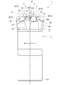
図1から図4に示すように、掘削ビット1は、工具中心軸Oを中心とする柱状のビット本体2と、ビット本体2の両端部(第1端部2aおよび第2端部2b)のうち第1端部2aに配置され、チップ中心軸Cを中心とする回転対称となる位置に、柱状の掘削チップ3と、ブロー孔5と、排出流路4とを備える。
As shown in FIGS. 1 to 4, the excavation bit 1 includes a columnar bit body 2 centered on the tool center axis O and both end portions (first end portion 2a and second end portion 2b) of the bit body 2. Among them, a columnar excavation chip 3, a blow hole 5, and a discharge flow path 4 are provided at a position which is arranged at the first end portion 2a and is rotationally symmetric with respect to the chip central axis C.
〔方向の定義〕
本実施形態では、ビット本体2の工具中心軸Oが延びる方向を工具軸方向と呼ぶ。工具軸方向のうち、ビット本体2の第2端部2bから第1端部2aへ向かう方向を、工具軸方向の先端側または単に先端側と呼び、第1端部2aから第2端部2bへ向かう方向を、工具軸方向の後端側または単に後端側と呼ぶ。
工具中心軸Oと直交する方向を工具径方向と呼ぶ。工具径方向のうち、工具中心軸Oに近づく方向を工具径方向の内側と呼び、工具中心軸Oから離れる方向を工具径方向の外側と呼ぶ。
工具中心軸O回りに周回する方向を工具周方向と呼ぶ。工具周方向のうち、掘削時に掘削装置および中継ロッドによって掘削ビット1が回転させられる方向を、工具回転方向Tと呼び、これとは反対の回転方向を、工具回転方向Tとは反対側または単に反工具回転方向と呼ぶ。なお本実施形態では、工具周方向の一方側が、工具回転方向Tに相当し、工具周方向の他方側が、反工具回転方向に相当する。
[Definition of direction]
In the present embodiment, the direction in which the tool center axis O of the bit body 2 extends is referred to as the tool axis direction. Of the tool axis directions, the direction from the second end 2b of the bit body 2 toward the first end 2a is called the tip side or simply the tip side in the tool axis direction, and the direction from the first end 2a to the second end 2b is called. The direction toward the tool axis is called the rear end side or simply the rear end side in the tool axis direction.
The direction orthogonal to the tool center axis O is called the tool radial direction. Of the tool radial directions, the direction approaching the tool center axis O is referred to as the inside in the tool radial direction, and the direction away from the tool center axis O is referred to as the outside in the tool radial direction.
The direction that orbits around the tool center axis O is called the tool circumferential direction. Of the tool circumferential directions, the direction in which the excavation bit 1 is rotated by the excavator and the relay rod during excavation is called the tool rotation direction T, and the rotation direction opposite to this is the side opposite to the tool rotation direction T or simply. It is called the anti-tool rotation direction. In this embodiment, one side in the tool circumferential direction corresponds to the tool rotation direction T, and the other side in the tool circumferential direction corresponds to the anti-tool rotation direction.
また、掘削チップ3のチップ中心軸Cが延びる方向をチップ軸方向と呼ぶ。掘削チップ3は、その一端部がビット本体2の表面から突出しており、その他端部がビット本体2の内部に埋め込まれている。本実施形態では、チップ軸方向のうち、掘削チップ3の他端部から一端部へ向かう方向を、チップ軸方向の先端側と呼び、一端部から他端部へ向かう方向を、チップ軸方向の後端側と呼ぶ。
チップ中心軸Cと直交する方向をチップ径方向と呼ぶ。
チップ中心軸C回りに周回する方向をチップ周方向と呼ぶ。
Further, the direction in which the tip central axis C of the drilling tip 3 extends is referred to as the tip axis direction. One end of the excavation tip 3 protrudes from the surface of the bit body 2, and the other end is embedded inside the bit body 2. In the present embodiment, of the tip axial directions, the direction from the other end to the one end of the excavated tip 3 is called the tip side in the tip axial direction, and the direction from one end to the other end is the tip axial direction. Called the rear end side.
The direction orthogonal to the chip center axis C is called the chip radial direction.
The direction that orbits around the chip center axis C is called the chip circumferential direction.
〔ビット本体〕
ビット本体2は、例えば鋼製である。ビット本体2は、工具軸方向に延びる円柱状である。図3および図4に示すように、ビット本体2の第1端部2aつまり先端部は、先端部以外の部分よりも外径が大きい。特に図示しないが、ビット本体2は、工具軸方向の後端側を向く端面つまり後端面に開口し、工具軸方向に同軸に延びる雌ネジ穴を有する。雌ネジ穴は、ビット本体2の第1端部2a以外の部分、つまり先端部以外の部分に配置される。この構成より、ビット本体2は、工具軸方向の後端側に開口する有底円筒状であるとも言える。
[Bit body]
The bit body 2 is made of, for example, steel. The bit body 2 is a columnar shape extending in the tool axis direction. As shown in FIGS. 3 and 4, the first end portion 2a of the bit body 2, that is, the tip portion has a larger outer diameter than the portion other than the tip portion. Although not particularly shown, the bit body 2 has a female screw hole that opens in the end face facing the rear end side in the tool axis direction, that is, the rear end face, and extends coaxially in the tool axis direction. The female screw hole is arranged in a portion other than the first end portion 2a of the bit body 2, that is, a portion other than the tip portion. From this configuration, it can be said that the bit body 2 has a bottomed cylindrical shape that opens toward the rear end side in the tool axis direction.
特に図示しないが、ビット本体2の雌ネジ穴には、中継ロッドの先端部の雄ネジが螺着される。ビット本体2には、掘削装置から中継ロッドを介して、工具中心軸O回りの回転力、工具軸方向の先端側への推力および打撃力が伝えられる。これにより掘削ビット1は、地盤や岩盤を破砕しながら進むことができ、削孔を形成する。またビット本体2の内部(雌ネジ穴内)には、内部に流路を有する中継ロッド等を介して水や圧縮エア等の流体が供給される。
Although not shown in particular, the male screw at the tip of the relay rod is screwed into the female screw hole of the bit body 2. The rotational force around the tool center axis O, the thrust toward the tip side in the tool axis direction, and the striking force are transmitted from the excavator to the bit body 2 via the relay rod. As a result, the excavation bit 1 can proceed while crushing the ground and rock, and forms a hole. Further, a fluid such as water or compressed air is supplied to the inside of the bit body 2 (inside the female screw hole) via a relay rod or the like having a flow path inside.
ビット本体2は、先端面21と、外周面22と、を有する。
先端面21は、工具軸方向の先端側を向くフェイス面23と、フェイス面23の工具径方向の外側に配置され、工具径方向の外側へ向かうに従い工具軸方向の後端側に位置するゲージ面24とを有する。すなわちゲージ面24は、工具軸方向の先端側かつ工具径方向の外側を向く。
The bit body 2 has a front end surface 21 and an outer peripheral surface 22.
The tip surface 21 is arranged on the outside of the face surface 23 facing the tip side in the tool axis direction and the outside of the face surface 23 in the tool radial direction, and is located on the rear end side in the tool axis direction toward the outside in the tool radial direction. It has a surface 24. That is, the gauge surface 24 faces the tip side in the tool axis direction and the outside in the tool radial direction.
図1および図2に示すように、フェイス面23は、工具周方向に並ぶ複数のフェイス座面23aを有する。本実施形態ではフェイス座面23aが、フェイス面23に沿って、工具中心軸Oを中心として工具周方向に120°間隔で並んで3つ設けられている。図3および図4に示すように、フェイス座面23aは、工具中心軸Oと垂直な方向に拡がる平面である。各フェイス座面23aには、図示しない円形の取付穴がそれぞれ開口する。各取付穴は、フェイス座面23aと直交する方向、つまり工具中心軸Oと平行(工具軸方向)に延びる。
As shown in FIGS. 1 and 2, the face surface 23 has a plurality of face seat surfaces 23a arranged in the tool circumferential direction. In the present embodiment, three face seating surfaces 23a are provided along the face surface 23, arranged side by side at intervals of 120 ° in the tool circumferential direction with the tool center axis O as the center. As shown in FIGS. 3 and 4, the face seating surface 23a is a plane extending in a direction perpendicular to the tool center axis O. A circular mounting hole (not shown) is opened in each face seat surface 23a. Each mounting hole extends in a direction orthogonal to the face bearing surface 23a, that is, parallel to the tool center axis O (tool axis direction).
図1および図2に示すように、ゲージ面24は、工具周方向に並ぶ複数のゲージ座面(座面)24aを有する。本実施形態ではゲージ座面24aが、ゲージ面24に沿って工具周方向に略60°毎に並んで6つ設けられる。ゲージ座面24aは、工具軸方向の先端側かつ工具径方向の外側を向く(すなわち工具軸方向の先端側と工具径方向の外側との中間方向を向く)平面である。ゲージ座面24aは、工具周方向の一方側つまり工具回転方向Tへ向かうに従い、工具軸方向の後端側に位置する傾斜面である。またゲージ座面24aは、工具回転方向Tへ向かうに従い、工具径方向の内側に位置する傾斜面でもある。各ゲージ座面24aには、図示しない円形の取付穴がそれぞれ開口する。各取付穴は、ゲージ座面24aと直交する方向、つまり工具中心軸Oに対して傾斜する方向に延びる。具体的に、各取付穴の中心軸と工具中心軸Oとは、ねじれの位置にある。
As shown in FIGS. 1 and 2, the gauge surface 24 has a plurality of gauge seat surfaces (seat surfaces) 24a arranged in the tool circumferential direction. In the present embodiment, six gauge seating surfaces 24a are provided along the gauge surface 24 in the circumferential direction of the tool at intervals of approximately 60 °. The gauge bearing surface 24a is a plane facing the tip side in the tool axis direction and the outside in the tool radial direction (that is, facing the intermediate direction between the tip side in the tool axis direction and the outside in the tool radial direction). The gauge bearing surface 24a is an inclined surface located on one side in the tool circumferential direction, that is, on the rear end side in the tool axial direction toward the tool rotation direction T. Further, the gauge seat surface 24a is also an inclined surface located inside in the tool radial direction toward the tool rotation direction T. A circular mounting hole (not shown) is opened in each gauge seat surface 24a. Each mounting hole extends in a direction orthogonal to the gauge bearing surface 24a, that is, in a direction inclined with respect to the tool center axis O. Specifically, the central axis of each mounting hole and the tool central axis O are in twisted positions.
図3および図4に示すように、外周面22のうち先端部は、先端部以外の部分よりも外径が大きい。外周面22の先端部は、工具軸方向の先端側へ向かうに従い外径が大きくなるテーパ状である。外周面22の先端部は、ゲージ面24の工具径方向の外端部と接続される。
As shown in FIGS. 3 and 4, the tip portion of the outer peripheral surface 22 has a larger outer diameter than the portion other than the tip portion. The tip of the outer peripheral surface 22 has a tapered shape in which the outer diameter increases toward the tip side in the tool axis direction. The tip of the outer peripheral surface 22 is connected to the outer end of the gauge surface 24 in the tool radial direction.
〔掘削チップ〕
掘削チップ3は、例えば超硬合金製である。なお掘削チップ3は、そのチップ軸方向の先端部に、多結晶ダイヤモンド焼結体製等の硬質層が被覆されていてもよい。
[Excavation tip]
The excavation tip 3 is made of, for example, cemented carbide. The excavated tip 3 may be coated with a hard layer made of a polycrystalline diamond sintered body or the like at the tip portion in the tip axial direction.
掘削チップ3は、ビット本体2の先端面21から突出する。掘削チップ3は、先端面21に複数設けられる。各掘削チップ3は、フェイス座面23aおよびゲージ座面24aの各取付穴に対して、圧入や焼き嵌め等によって締まり嵌めされたり、ロウ付けされたりすることにより固定される。各掘削チップ3のチップ中心軸Cは、各掘削チップ3が配置されるフェイス座面23aまたはゲージ座面24aに対して、直交する方向に延びる。
The excavation tip 3 protrudes from the tip surface 21 of the bit body 2. A plurality of excavation tips 3 are provided on the tip surface 21. Each excavation tip 3 is fixed to each mounting hole of the face seat surface 23a and the gauge seat surface 24a by being tightened and fitted by press fitting, shrink fitting, or the like, or brazed. The tip central axis C of each excavation tip 3 extends in a direction orthogonal to the face seat surface 23a or the gauge seat surface 24a on which each excavation tip 3 is arranged.
具体的に、掘削チップ3のチップ軸方向の先端部は、ビット本体2の先端面21から突出し、外部に露出される。特に図示しないが、掘削チップ3のチップ軸方向の先端部以外の部分は、取付穴内に埋め込まれる。掘削チップ3のチップ軸方向の先端部は、チップ軸方向の先端側へ向かうに従い外径が小さくなる。掘削チップ3のチップ軸方向の先端部以外の部分は、チップ軸方向に沿って外径が一定とされた円柱状である。
Specifically, the tip portion of the excavation tip 3 in the tip axial direction protrudes from the tip surface 21 of the bit body 2 and is exposed to the outside. Although not particularly shown, a portion of the excavation tip 3 other than the tip portion in the tip axial direction is embedded in the mounting hole. The outer diameter of the tip portion of the excavation tip 3 in the tip axial direction becomes smaller toward the tip side in the tip axial direction. The portion of the excavation tip 3 other than the tip portion in the tip axial direction is a columnar shape having a constant outer diameter along the tip axial direction.
本実施形態の掘削チップ3は、チップ軸方向の先端部が略円錐状とされた、いわゆるスパイクチップである。
掘削チップ3は、チップ軸方向の先端部に配置される凸曲面状の刃先部3aと、チップ軸方向の先端部に配置され、刃先部3aよりもチップ軸方向の後端側に位置するテーパ部3bと、を有する。
The excavation tip 3 of the present embodiment is a so-called spike tip in which the tip portion in the tip axial direction is substantially conical.
The excavation tip 3 has a convex curved cutting edge portion 3a arranged at the tip end portion in the tip axial direction and a taper arranged at the tip end portion in the tip axial direction and located on the rear end side in the tip axial direction with respect to the cutting edge portion 3a. It has a part 3b and.
刃先部3aは、掘削チップ3のチップ軸方向の最先端に位置する。刃先部3aは、略半球状である。例えばチップ中心軸Cを含む掘削チップ3の縦断面視において、刃先部3aの曲率半径は、掘削チップ3の外径寸法(チップ径方向の直径寸法)の1/2未満である。なお、上記掘削チップ3の外径寸法とは、掘削チップ3の最大径部分の外径寸法を指しており、具体的には、掘削チップ3の先端部以外の部分(円柱状部分)の外径寸法である。
テーパ部3bは、刃先部3aのチップ軸方向の後端部に接続される。テーパ部3bは、チップ軸方向の後端側へ向かうに従い外径が大きくなるテーパ状である。
The cutting edge portion 3a is located at the tip end of the excavation tip 3 in the tip axial direction. The cutting edge portion 3a is substantially hemispherical. For example, in the vertical cross-sectional view of the excavation chip 3 including the chip central axis C, the radius of curvature of the cutting edge portion 3a is less than 1/2 of the outer diameter dimension (diameter dimension in the chip radial direction) of the excavation chip 3. The outer diameter dimension of the excavation tip 3 refers to the outer diameter dimension of the maximum diameter portion of the excavation tip 3, and specifically, the outside of the portion (cylindrical portion) other than the tip portion of the excavation tip 3. It is a diameter dimension.
The tapered portion 3b is connected to the rear end portion of the cutting edge portion 3a in the tip axial direction. The tapered portion 3b has a tapered shape in which the outer diameter increases toward the rear end side in the chip axial direction.
図1に示すように、複数の掘削チップ3は、フェイス面23に配置されるフェイスチップ3Aと、ゲージ面24に配置されるゲージチップ3Bとを含む。本実施形態では、フェイスチップ3Aの外径寸法に比べて、ゲージチップ3Bの外径寸法が大きい。また、フェイスチップ3Aのチップ軸方向の先端部がフェイス面23から突出する突出量に比べて、ゲージチップ3Bのチップ軸方向の先端部がゲージ面24から突出する突出量が大きい。
As shown in FIG. 1, the plurality of excavation tips 3 include a face tip 3A arranged on the face surface 23 and a gauge tip 3B arranged on the gauge surface 24. In the present embodiment, the outer diameter of the gauge tip 3B is larger than the outer diameter of the face tip 3A. Further, the tip portion of the gauge tip 3B in the chip axial direction protrudes from the gauge surface 24 in a larger amount than the tip portion of the face tip 3A in the chip axial direction protrudes from the face surface 23.
フェイスチップ3Aは、フェイス面23に複数設けられる。すなわち、複数の掘削チップ3には、複数のフェイスチップ3Aが含まれる。本実施形態ではフェイスチップ3Aが、フェイス面23に工具周方向に並んで3つ設けられる。フェイスチップ3Aは、各フェイス座面23aにそれぞれ設けられる。本実施形態では、1つのフェイス座面23aに対して、1つのフェイスチップ3Aが配置される。図2から図4に示すように、フェイスチップ3Aのチップ中心軸Cは、工具軸方向に延びる。
A plurality of face chips 3A are provided on the face surface 23. That is, the plurality of excavation tips 3 includes the plurality of face tips 3A. In this embodiment, three face chips 3A are provided on the face surface 23 side by side in the tool circumferential direction. The face chip 3A is provided on each face seat surface 23a. In the present embodiment, one face chip 3A is arranged with respect to one face seat surface 23a. As shown in FIGS. 2 to 4, the tip central axis C of the face tip 3A extends in the tool axis direction.
図1に示すように、ゲージチップ3Bは、ゲージ面24に複数設けられる。すなわち、複数の掘削チップ3には、複数のゲージチップ3Bが含まれる。本実施形態ではゲージチップ3Bが、ゲージ面24に工具周方向に並んで6つ設けられる。ゲージチップ3Bは、各ゲージ座面24aにそれぞれ設けられる。本実施形態では、1つのゲージ座面24aに対して、1つのゲージチップ3Bが配置される。図2から図4に示すように、ゲージチップ3Bのチップ中心軸Cは、工具軸方向の後端側へ向かうに従い、工具径方向の内側へ向けて延びる。ゲージチップ3Bのチップ中心軸Cは、工具軸方向の後端側へ向かうに従い、工具周方向のうち工具回転方向Tとは反対側に向けて延びる。
As shown in FIG. 1, a plurality of gauge tips 3B are provided on the gauge surface 24. That is, the plurality of excavation tips 3 includes a plurality of gauge tips 3B. In this embodiment, six gauge tips 3B are provided on the gauge surface 24 side by side in the tool circumferential direction. The gauge tip 3B is provided on each gauge seat surface 24a. In the present embodiment, one gauge tip 3B is arranged with respect to one gauge seat surface 24a. As shown in FIGS. 2 to 4, the tip central axis C of the gauge tip 3B extends inward in the tool radial direction toward the rear end side in the tool axis direction. The tip center axis C of the gauge tip 3B extends toward the rear end side in the tool axis direction and toward the side opposite to the tool rotation direction T in the tool circumferential direction.
〔ブロー孔〕
図1および図2に示すように、ブロー孔5は、ビット本体2の内部を延び、先端面21に開口する。ブロー孔5は、円孔状である。ブロー孔5は、ビット本体2の先端面21から工具軸方向の後端側へ向かうに従い、工具径方向の内側に位置する。つまりブロー孔5は、工具中心軸Oに対して傾斜して延びる。特に図示しないが、ブロー孔5は、ビット本体2の雌ネジ穴の内部と連通する。
[Blow hole]
As shown in FIGS. 1 and 2, the blow hole 5 extends inside the bit body 2 and opens to the tip surface 21. The blow hole 5 has a circular hole shape. The blow hole 5 is located inside in the tool radial direction from the tip surface 21 of the bit body 2 toward the rear end side in the tool axis direction. That is, the blow hole 5 is inclined and extends with respect to the tool center axis O. Although not particularly shown, the blow hole 5 communicates with the inside of the female screw hole of the bit body 2.
工具軸方向から見て、フェイスチップ3Aの工具中心軸O回りの回転軌跡(図示省略)に対して、ブロー孔5は、工具径方向の内側に位置し、または重なる。本実施形態では、図2に示すように工具軸方向から見て、フェイスチップ3Aの工具中心軸O回りの回転軌跡と、ブロー孔5とが、互いに重なる。
ブロー孔5は、複数設けられる。本実施形態ではブロー孔5が、工具周方向に並んで3つ設けられ、隣り合う二つのフェイスチップ3Aの間にブロー孔5がそれぞれ形成されている。
When viewed from the tool axis direction, the blow hole 5 is located or overlaps the inside of the tool radial direction with respect to the rotation locus (not shown) around the tool center axis O of the face tip 3A. In the present embodiment, as shown in FIG. 2, the rotation locus around the tool center axis O of the face tip 3A and the blow hole 5 overlap each other when viewed from the tool axis direction.
A plurality of blow holes 5 are provided. In the present embodiment, three blow holes 5 are provided side by side in the circumferential direction of the tool, and the blow holes 5 are formed between two adjacent face tips 3A.
〔排出流路〕
図1および図2に示すように、排出流路4は、ビット本体2の先端面21から外周面22にわたって配置される。排出流路4は、ビット本体2の先端面21から外周面22の先端部にわたって延びる。排出流路4には、ビット本体2の内部からブロー孔5を通して流体が供給される。排出流路4は、掘削チップ3が地盤や岩盤を破砕して生じた繰粉を、流体とともにビット本体2の先端面21から外周面22へ流し、ビット本体2の後端側へ送るための流路である。
[Discharge flow path]
As shown in FIGS. 1 and 2, the discharge flow path 4 is arranged from the front end surface 21 of the bit body 2 to the outer peripheral surface 22. The discharge flow path 4 extends from the tip end surface 21 of the bit body 2 to the tip end portion of the outer peripheral surface 22. A fluid is supplied to the discharge flow path 4 from the inside of the bit body 2 through the blow hole 5. The discharge flow path 4 is for flowing the powder generated by the excavation tip 3 crushing the ground or rock from the tip surface 21 of the bit body 2 to the outer peripheral surface 22 together with the fluid and sending it to the rear end side of the bit body 2. It is a flow path.
排出流路4は、第1流路41と、第2流路42と、第3流路43と、第4流路44と、を有する。排出流路4は、第1流路41、第2流路42、第3流路43および第4流路44の組を、複数組有する。本実施形態では、第1流路41、第2流路42、第3流路43および第4流路44の組が、工具周方向に並んで3組設けられる。すなわち、第1流路41、第2流路42、第3流路43および第4流路44はそれぞれ、工具周方向に並んで複数(各3つ)設けられる。
The discharge flow path 4 has a first flow path 41, a second flow path 42, a third flow path 43, and a fourth flow path 44. The discharge flow path 4 has a plurality of sets of a first flow path 41, a second flow path 42, a third flow path 43, and a fourth flow path 44. In the present embodiment, three sets of the first flow path 41, the second flow path 42, the third flow path 43, and the fourth flow path 44 are provided side by side in the tool circumferential direction. That is, a plurality (three each) of the first flow path 41, the second flow path 42, the third flow path 43, and the fourth flow path 44 are provided side by side in the tool circumferential direction.
第1流路41は、先端面21に位置して工具径方向に延びる溝状であり、第1流路41の途中にブロー孔5が開口する。第1流路41は、工具径方向において、工具周方向に隣り合う一対のフェイスチップ3A,3A間、および、工具周方向に隣り合う一対のゲージチップ3B,3B間にわたって配置される。第1流路41は、工具周方向に隣り合う一対のフェイス座面23a,23a間、および、工具周方向に隣り合う一対のゲージ座面24a,24a間を、工具径方向に延びる。具体的に、第1流路41は、工具径方向の外側へ向かうに従い、工具軸方向の後端側に位置する。特に図示しないが、工具中心軸Oを含む縦断面視で、第1流路41の溝底は、直線状に延びる。
The first flow path 41 has a groove shape located on the tip surface 21 and extends in the tool radial direction, and a blow hole 5 opens in the middle of the first flow path 41. The first flow path 41 is arranged between a pair of face tips 3A and 3A adjacent to each other in the tool circumferential direction in the tool radial direction and between a pair of gauge tips 3B and 3B adjacent to each other in the tool circumferential direction. The first flow path 41 extends in the tool radial direction between the pair of face seat surfaces 23a and 23a adjacent to each other in the tool circumferential direction and between the pair of gauge seat surfaces 24a and 24a adjacent to each other in the tool circumferential direction. Specifically, the first flow path 41 is located on the rear end side in the tool axis direction toward the outside in the tool radial direction. Although not particularly shown, the groove bottom of the first flow path 41 extends linearly in a vertical cross-sectional view including the tool center axis O.
複数の掘削チップ3のうち、第1流路41と工具周方向に隣り合う所定の掘削チップ3のチップ中心軸Cは、工具軸方向の後端側へ向かうに従い、工具周方向において第1流路41から離れる。具体的に本実施形態では、複数の掘削チップ3のうち、第1流路41の反工具回転方向に隣り合う所定のゲージチップ3Bのチップ中心軸Cが、工具軸方向の後端側へ向かうに従い、第1流路41から反工具回転方向に離れる。
Of the plurality of drilling tips 3, the tip central axis C of the predetermined drilling tip 3 adjacent to the first flow path 41 in the tool circumferential direction is the first flow in the tool circumferential direction toward the rear end side in the tool axis direction. Leave the road 41. Specifically, in the present embodiment, among the plurality of excavation tips 3, the tip central axis C of the predetermined gauge tip 3B adjacent to the first flow path 41 in the anti-tool rotation direction faces the rear end side in the tool axis direction. Therefore, it separates from the first flow path 41 in the anti-tool rotation direction.
第1流路41は、流量増加部41aと、流速増加部41bと、を有する。
流量増加部41aは、第1流路41のうち工具径方向の内側部分に配置される。流量増加部41aは、工具径方向の外側へ向かうに従い溝幅が広くなる。流量増加部41aには、ブロー孔5が開口する。
The first flow path 41 has a flow rate increasing section 41a and a flow velocity increasing section 41b.
The flow rate increasing portion 41a is arranged in the inner portion of the first flow path 41 in the tool radial direction. The groove width of the flow rate increasing portion 41a becomes wider toward the outside in the tool radial direction. A blow hole 5 is opened in the flow rate increasing portion 41a.
流速増加部41bは、第1流路41のうち工具径方向の外側部分に配置される。流速増加部41bは、工具径方向の外側へ向かうに従い溝幅が狭くなる。流速増加部41bは、ブロー孔5よりも工具径方向の外側に配置される。
The flow velocity increasing portion 41b is arranged in the outer portion of the first flow path 41 in the tool radial direction. The groove width of the flow velocity increasing portion 41b becomes narrower toward the outside in the tool radial direction. The flow velocity increasing portion 41b is arranged outside the blow hole 5 in the radial direction of the tool.
流速増加部41bは、工具周方向において互いに対向する一対の溝壁を有する。一対の溝壁のうち、流速増加部41bの反工具回転方向の端部に位置して工具回転方向Tを向く一方の溝壁の工具軸方向の高さは、流速増加部41bの工具回転方向Tの端部に位置して反工具回転方向を向く他方の溝壁の工具軸方向の高さよりも低い。このため、流速増加部41bを流れる流体の一部は、一方の溝壁を越えて、流速増加部41bの反工具回転方向に隣接するゲージ座面24a上へと流れる。
The flow velocity increasing portion 41b has a pair of groove walls facing each other in the tool circumferential direction. Of the pair of groove walls, the height in the tool axis direction of one of the groove walls located at the end of the flow velocity increasing portion 41b in the counter-tool rotation direction and facing the tool rotation direction T is the tool rotation direction of the flow velocity increasing portion 41b. It is lower than the height in the tool axis direction of the other groove wall located at the end of T and facing the anti-tool rotation direction. Therefore, a part of the fluid flowing through the flow velocity increasing portion 41b flows over one groove wall and onto the gauge seat surface 24a adjacent to the flow velocity increasing portion 41b in the counter-tool rotation direction.
複数の第1流路41は、各第1流路41の工具径方向の内端部を介して、互いに接続される。本実施形態では、3つの第1流路41の各流量増加部41aの工具径方向の内端部同士が、互いに直接的に接続される。複数の第1流路41は、工具中心軸O上を通して互いに連通する。
The plurality of first flow paths 41 are connected to each other via the inner end portion of each first flow path 41 in the tool radial direction. In the present embodiment, the inner end portions of the flow rate increasing portions 41a of the three first flow paths 41 in the tool radial direction are directly connected to each other. The plurality of first flow paths 41 communicate with each other through the tool center axis O.
第2流路42は、先端面21のうちブロー孔5よりも工具径方向の外側に位置して第1流路41と連通し、工具周方向に延びる。第2流路42は、第1流路41との接続部分から、工具周方向のうち少なくとも工具回転方向Tとは反対側へ向けて延びる。本実施形態では第2流路42が、第1流路41の流速増加部41bの反工具回転方向に隣接するゲージ座面24a上を含む。すなわち、第2流路42は、ゲージ座面24a上に位置し、第1流路41との接続部分から工具周方向の他方側つまり反工具回転方向に延びる。なお第2流路42は、工具周方向に隣り合う一対の第1流路41,41間に位置する複数(2つ)のゲージ座面24aにわたって延びていてもよい。
The second flow path 42 is located outside the blow hole 5 in the tip surface 21 in the tool radial direction, communicates with the first flow path 41, and extends in the tool circumferential direction. The second flow path 42 extends from the connection portion with the first flow path 41 toward at least the side opposite to the tool rotation direction T in the tool circumferential direction. In the present embodiment, the second flow path 42 includes the gauge seat surface 24a adjacent to the flow velocity increasing portion 41b of the first flow path 41 in the counter-tool rotation direction. That is, the second flow path 42 is located on the gauge seat surface 24a and extends from the connection portion with the first flow path 41 on the other side in the tool circumferential direction, that is, in the anti-tool rotation direction. The second flow path 42 may extend over a plurality of (two) gauge seating surfaces 24a located between the pair of first flow paths 41 and 41 adjacent to each other in the tool circumferential direction.
第3流路43は、外周面22に位置して工具軸方向に延びる溝状であり、第1流路41の工具径方向の外端部と接続される。第3流路43は、外周面22の先端部に配置され、その工具軸方向の先端部が先端面21に開口する。具体的に、第3流路43は、流速増加部41bの工具径方向の外端部と接続され、ゲージ面24に開口する。第3流路43は、工具周方向において一対のゲージチップ3B,3B間に位置する。第3流路43の溝幅は、第1流路41の溝幅以上である。第3流路43の溝底は、工具軸方向の後端側へ向かうに従い、工具径方向の外側に位置する。つまり第3流路43は、工具軸方向の後端側へ向かうに従い溝深さが浅くなる。
The third flow path 43 is located on the outer peripheral surface 22 and has a groove shape extending in the tool axis direction, and is connected to the outer end portion of the first flow path 41 in the tool radial direction. The third flow path 43 is arranged at the tip end portion of the outer peripheral surface 22, and the tip end portion in the tool axial direction opens to the tip end surface 21. Specifically, the third flow path 43 is connected to the outer end portion of the flow velocity increasing portion 41b in the tool radial direction and opens to the gauge surface 24. The third flow path 43 is located between the pair of gauge tips 3B, 3B in the tool circumferential direction. The groove width of the third flow path 43 is equal to or larger than the groove width of the first flow path 41. The groove bottom of the third flow path 43 is located outside in the tool radial direction toward the rear end side in the tool axial direction. That is, the groove depth of the third flow path 43 becomes shallower toward the rear end side in the tool axis direction.
第4流路44は、外周面22に位置して工具軸方向に延びる溝状であり、第2流路42と連通する。第4流路44は、外周面22の先端部に配置され、その工具軸方向の先端部が先端面21に開口する。具体的に、第4流路44は、ゲージ面24に開口する。第4流路44は、工具周方向において一対のゲージチップ3B,3B間に位置する。第4流路44は、第1流路41および第3流路43の反工具回転方向に位置する。第4流路44の溝幅は、第1流路41の溝幅以上である。本実施形態では、第4流路44の溝幅と第3流路43の溝幅とが、互いに略同じである。第4流路44の溝底は、工具軸方向の後端側へ向かうに従い、工具径方向の外側に位置する。つまり第4流路44は、工具軸方向の後端側へ向かうに従い溝深さが浅くなる。
The fourth flow path 44 is located on the outer peripheral surface 22 and has a groove shape extending in the tool axis direction, and communicates with the second flow path 42. The fourth flow path 44 is arranged at the tip end portion of the outer peripheral surface 22, and the tip end portion in the tool axial direction opens to the tip end surface 21. Specifically, the fourth flow path 44 opens to the gauge surface 24. The fourth flow path 44 is located between the pair of gauge tips 3B, 3B in the tool circumferential direction. The fourth flow path 44 is located in the anti-tool rotation direction of the first flow path 41 and the third flow path 43. The groove width of the fourth flow path 44 is equal to or larger than the groove width of the first flow path 41. In the present embodiment, the groove width of the fourth flow path 44 and the groove width of the third flow path 43 are substantially the same as each other. The groove bottom of the fourth flow path 44 is located outside in the tool radial direction toward the rear end side in the tool axial direction. That is, the groove depth of the fourth flow path 44 becomes shallower toward the rear end side in the tool axis direction.
〔本実施形態による作用効果〕
以上説明した本実施形態の掘削ビット1によれば、排出流路4が、工具径方向に延びる第1流路41と、工具周方向に延びる第2流路42と、を有するので、ビット本体2の先端面21に広範囲に流体を行き渡らせることができる。
具体的に、第2流路42は、ブロー孔5よりも工具径方向の外側に位置している。このため、ブロー孔5から第1流路41に流出した流体は、第1流路41に沿って工具径方向に流れ、その後、第2流路42に流入して工具周方向にも流れる。このように、ブロー孔5から第1流路41に流出した流体が、まず工具径方向の外側へ向けて流れることにより、流体の流速の低下が抑えられ、繰粉をビット本体2の後端側へ向けて押し出す力が安定して高められる。したがって、繰粉を効率よく安定して排出させることができる。
[Action and effect of this embodiment]
According to the excavation bit 1 of the present embodiment described above, since the discharge flow path 4 has a first flow path 41 extending in the tool radial direction and a second flow path 42 extending in the tool circumferential direction, the bit main body The fluid can be spread over a wide range on the tip surface 21 of 2.
Specifically, the second flow path 42 is located outside the blow hole 5 in the tool radial direction. Therefore, the fluid flowing out from the blow hole 5 to the first flow path 41 flows in the tool radial direction along the first flow path 41, then flows into the second flow path 42, and also flows in the tool circumferential direction. In this way, the fluid flowing out from the blow hole 5 to the first flow path 41 first flows outward in the tool radial direction, so that the decrease in the flow velocity of the fluid is suppressed, and the powder is pulverized at the rear end of the bit body 2. The force to push it toward the side is stably increased. Therefore, the milled powder can be discharged efficiently and stably.
また本実施形態によれば、繰粉を効率よく排出できるので、掘削チップ3による破砕性つまり掘削性能が良好に維持される。具体的には、例えば従来のように破砕された繰粉がビット先端に残ることで、繰粉が2次破砕されるような不具合が、本実施形態では抑制される。このため、削孔速度を向上でき、単位時間あたりの掘進距離を延ばすことができる。その結果、掘削ビット1が疲労限界を迎えるまでに掘削できる時間(距離)を延長することができ、つまり工具寿命の長寿命化を図ることができる。
Further, according to the present embodiment, since the milled powder can be efficiently discharged, the crushability by the excavation tip 3, that is, the excavation performance is well maintained. Specifically, for example, the problem that the crushed powder remains at the tip of the bit as in the conventional case and the crushed powder is secondarily crushed is suppressed in the present embodiment. Therefore, the drilling speed can be improved and the excavation distance per unit time can be extended. As a result, the time (distance) that the excavation bit 1 can excavate before reaching the fatigue limit can be extended, that is, the tool life can be extended.
また本実施形態では、第2流路42が、第1流路41との接続部分から、工具周方向のうち少なくとも工具回転方向Tとは反対側へ向けて延びる。
この場合、掘削時に、掘削ビット1が工具中心軸O回りの工具回転方向Tに回転させられたときに、第2流路42を流れる流体が、工具回転方向Tとは反対側へ向けて、つまり工具周方向において第1流路41から離れる向きへと流れやすくなる。このため、繰粉をより効率よく排出できる。
Further, in the present embodiment, the second flow path 42 extends from the connection portion with the first flow path 41 toward at least the side opposite to the tool rotation direction T in the tool circumferential direction.
In this case, when the excavation bit 1 is rotated in the tool rotation direction T around the tool center axis O during excavation, the fluid flowing through the second flow path 42 is directed to the side opposite to the tool rotation direction T. That is, it becomes easy to flow in the direction away from the first flow path 41 in the tool circumferential direction. Therefore, the milling powder can be discharged more efficiently.
また本実施形態では、排出流路4が、工具軸方向に延びる第3流路43を有しており、第1流路41を工具径方向の外側へ向けて流れる流体が、第3流路43を通してビット本体2の後端側へと流される。排出流路4においてビット本体2の後端側へ向かう流体の流速の低下が抑えられるため、繰粉を後端側へ押し出す力が良好に維持され、繰粉の排出性が安定して高められる。
Further, in the present embodiment, the discharge flow path 4 has a third flow path 43 extending in the tool axis direction, and the fluid flowing through the first flow path 41 toward the outside in the tool radial direction is the third flow path. It is flowed to the rear end side of the bit body 2 through 43. Since the decrease in the flow velocity of the fluid toward the rear end side of the bit body 2 is suppressed in the discharge flow path 4, the force for pushing the powder to the rear end side is maintained satisfactorily, and the dischargeability of the powder is stably enhanced. ..
また本実施形態では、図2に示すように工具軸方向から見て、フェイスチップ3Aの工具中心軸O回りの回転軌跡(図示省略)に、ブロー孔5の少なくとも一部が重なる。または、特に図示しないが工具軸方向から見て、フェイスチップ3Aの工具中心軸O回りの回転軌跡よりも、ブロー孔5が工具径方向の内側に位置する。
この場合、フェイスチップ3Aが掘削して生じた繰粉が、ブロー孔5から流出した流体によって工具径方向の外側へ向けて流れやすい。このため、ビット先端に繰粉が残されるような不具合が抑制される。
なお本実施形態のように、フェイスチップ3Aの工具中心軸O回りの回転軌跡と、ブロー孔5とが、互いに重なる場合には、ブロー孔5から流出した流体が、流出直後に工具周方向へと流れるようなことがフェイスチップ3Aにより抑えられる。このため、ブロー孔5から工具径方向へ向けた流体の流れがより安定し、流体の流速が高められる。
Further, in the present embodiment, as shown in FIG. 2, when viewed from the tool axis direction, at least a part of the blow hole 5 overlaps the rotation locus (not shown) around the tool center axis O of the face tip 3A. Alternatively, although not particularly shown, the blow hole 5 is located inside the tool radial direction with respect to the rotation locus around the tool center axis O of the face tip 3A when viewed from the tool axis direction.
In this case, the milling powder generated by excavating the face tip 3A tends to flow outward in the tool radial direction by the fluid flowing out from the blow hole 5. Therefore, the problem that the powder is left at the tip of the bit is suppressed.
When the rotation locus around the tool center axis O of the face tip 3A and the blow hole 5 overlap each other as in the present embodiment, the fluid flowing out from the blow hole 5 flows out in the tool circumferential direction immediately after the outflow. The face chip 3A suppresses the flow. Therefore, the flow of the fluid from the blow hole 5 in the radial direction of the tool is more stable, and the flow velocity of the fluid is increased.
また本実施形態では、ゲージチップ3Bが設けられるゲージ座面(座面)24aが、工具周方向の一方側(工具回転方向T)へ向かうに従い、工具軸方向の後端側に位置し、第2流路42は、ゲージ座面24a上に位置し、第1流路41との接続部分から工具周方向の他方側(反工具回転方向)に延びる。
この場合、ゲージチップ3Bが配置されるゲージ座面24aが第2流路42としても機能するので、ビット本体2の先端面21の構造を簡素化しつつ、上述の本実施形態による作用効果が得られる。
Further, in the present embodiment, the gauge seat surface (seat surface) 24a on which the gauge tip 3B is provided is located on the rear end side in the tool axial direction as it is directed to one side in the tool circumferential direction (tool rotation direction T). The two flow paths 42 are located on the gauge bearing surface 24a and extend from the connection portion with the first flow path 41 to the other side in the tool circumferential direction (counter-tool rotation direction).
In this case, since the gauge seat surface 24a on which the gauge tip 3B is arranged also functions as the second flow path 42, the operation and effect according to the above-described embodiment can be obtained while simplifying the structure of the tip surface 21 of the bit body 2. Be done.
また本実施形態では、複数の掘削チップ3のうち、第1流路41と工具周方向に隣り合う所定の掘削チップ3、具体的には、第1流路41の反工具回転方向に隣り合う所定のゲージチップ3Bのチップ中心軸Cが、工具軸方向の後端側へ向かうに従い、工具周方向において第1流路41から離れる。
本実施形態では、上述のように第1流路41を流れる流体の流速が高められる分、第1流路41近傍の摩耗の進行が早まる可能性がある。そこで上記構成を採用することにより、第1流路41と隣り合う所定の掘削チップ3(ゲージチップ3B)と、第1流路41との間の肉厚が大きく確保されて、第1流路41近傍の摩耗による掘削チップ3のビット本体2からの脱落が抑制される。
Further, in the present embodiment, among the plurality of excavation tips 3, a predetermined excavation tip 3 adjacent to the first flow path 41 in the tool circumferential direction, specifically, adjacent to the first flow path 41 in the anti-tool rotation direction. The tip central axis C of the predetermined gauge tip 3B moves away from the first flow path 41 in the tool circumferential direction toward the rear end side in the tool axis direction.
In the present embodiment, as described above, the flow velocity of the fluid flowing through the first flow path 41 is increased, so that the progress of wear in the vicinity of the first flow path 41 may be accelerated. Therefore, by adopting the above configuration, a large wall thickness is secured between the predetermined excavation tip 3 (gauge tip 3B) adjacent to the first flow path 41 and the first flow path 41, and the first flow path is secured. The excavation tip 3 is suppressed from falling off from the bit body 2 due to wear in the vicinity of 41.
また本実施形態では、ゲージチップ3Bのチップ中心軸Cが、工具軸方向の後端側へ向かうに従い、工具周方向のうち工具回転方向Tとは反対側に向けて延びる。
この場合、掘削時にゲージチップ3Bは、工具回転方向Tへの回転力によりゲージチップ3Bに作用する曲げ応力を、チップ軸方向への圧縮応力として受け止めて緩和することができる。このため、ゲージチップ3Bの折損等が抑制される。
Further, in the present embodiment, the tip central axis C of the gauge tip 3B extends toward the rear end side in the tool axis direction and toward the side opposite to the tool rotation direction T in the tool circumferential direction.
In this case, the gauge tip 3B can receive and relax the bending stress acting on the gauge tip 3B due to the rotational force in the tool rotation direction T as the compressive stress in the tip axial direction during excavation. Therefore, breakage of the gauge tip 3B and the like are suppressed.
また本実施形態では、掘削チップ3の刃先部3aの曲率半径が、掘削チップ3の先端部以外の部分の外径(直径)寸法の1/2未満である。
この場合、掘削チップ3はいわゆるスパイクチップ等であり、掘削チップ3の先端部が尖って形成されるため、削孔速度をより高めることができる。また、掘削チップ3が先鋭形状とされることにより、掘削チップ3の先端部近傍において流体が流れるスペースが確保され、繰粉の排出性がより高められる。
Further, in the present embodiment, the radius of curvature of the cutting edge portion 3a of the excavation tip 3 is less than 1/2 of the outer diameter (diameter) dimension of the portion other than the tip portion of the excavation tip 3.
In this case, the excavation tip 3 is a so-called spike tip or the like, and since the tip portion of the excavation tip 3 is formed sharply, the drilling speed can be further increased. Further, since the excavation tip 3 has a sharp shape, a space through which the fluid flows is secured in the vicinity of the tip portion of the excavation tip 3, and the powder discharge property is further improved.
また本実施形態では、排出流路4が、工具軸方向に延びる第4流路44を有しており、第2流路42を流れる流体が、第4流路44を通してビット本体2の後端側へと流される。このため、繰粉の排出性がより高められる。
Further, in the present embodiment, the discharge flow path 4 has a fourth flow path 44 extending in the tool axis direction, and the fluid flowing through the second flow path 42 passes through the fourth flow path 44 to the rear end of the bit body 2. It is swept to the side. Therefore, the dischargeability of the milled powder is further improved.
また本実施形態では、第1流路41が流速増加部41bを有し、流速増加部41bは、ブロー孔5よりも工具径方向の外側に配置され、工具径方向の外側へ向かうに従い溝幅が狭くなる。
この場合、ブロー孔5から第1流路41に流出した流体が、工具径方向の外側へ向けて流速増加部41bを流れることによって、より流速が高められる。このため、繰粉の排出性が安定して高められる。
Further, in the present embodiment, the first flow path 41 has a flow velocity increasing portion 41b, and the flow velocity increasing portion 41b is arranged outside the blow hole 5 in the tool radial direction, and the groove width increases toward the outside in the tool radial direction. Becomes narrower.
In this case, the fluid flowing out from the blow hole 5 to the first flow path 41 flows outward in the tool radial direction through the flow velocity increasing portion 41b, so that the flow velocity is further increased. Therefore, the dischargeability of the milled powder is stably enhanced.
また本実施形態では、第1流路41が流量増加部41aを有し、流量増加部41aは、工具径方向の外側へ向かうに従い溝幅が広くなり、流量増加部41aにブロー孔5が開口する。
この場合、ブロー孔5から流量増加部41aに流出した直後の流体が、溝幅が広い方向へ向けて、つまり工具径方向の外側へ向けて流れやすくなる。すなわち、ブロー孔5から流量増加部41aに流出した流体のうち、工具径方向の内側へ向けて流れる流体の流量に比べて、工具径方向の外側へ向けて流れる流体の流量が多くなるため、流体が全体として工具径方向の外側へ向けて流れやすくなる。このため、第1流路41の流体が、工具径方向の外側へ向けて安定して流れやすくなり、繰粉の排出性を高めることができる。
Further, in the present embodiment, the first flow path 41 has a flow rate increasing portion 41a, the flow rate increasing portion 41a has a groove width widening toward the outside in the tool radial direction, and a blow hole 5 is opened in the flow rate increasing portion 41a. do.
In this case, the fluid immediately after flowing out from the blow hole 5 to the flow rate increasing portion 41a tends to flow in the direction in which the groove width is wide, that is, in the outward direction in the tool radial direction. That is, among the fluid flowing out from the blow hole 5 to the flow rate increasing portion 41a, the flow rate of the fluid flowing outward in the tool radial direction is larger than the flow rate of the fluid flowing inward in the tool radial direction. The fluid as a whole tends to flow outward in the radial direction of the tool. Therefore, the fluid in the first flow path 41 can easily flow stably toward the outside in the radial direction of the tool, and the dischargeability of the milled powder can be improved.
また本実施形態では、第1流路41が、工具周方向に並んで複数設けられ、複数の第1流路41は、各第1流路41の工具径方向の内端部を介して、互いに接続される。
この場合、ビット本体2の先端面21の中央部(工具中心軸O上)近傍においても、繰粉の排出性を安定して高めることができる。
Further, in the present embodiment, a plurality of first flow paths 41 are provided side by side in the tool circumferential direction, and the plurality of first flow paths 41 are provided via the inner end portion of each first flow path 41 in the tool radial direction. Connected to each other.
In this case, the powder discharge property can be stably improved even in the vicinity of the central portion (on the tool center axis O) of the tip surface 21 of the bit body 2.
また本実施形態では、掘削チップ3のチップ中心軸Cが、掘削チップ3が配置されるフェイス座面23aまたはゲージ座面24aに対して、直交する方向に延びる。
この場合、掘削チップ3が摩耗して再研磨を行う際には、各座面23a,24aを基準とすることにより正確に再研磨を行うことができる。
Further, in the present embodiment, the tip central axis C of the excavation tip 3 extends in a direction orthogonal to the face seat surface 23a or the gauge seat surface 24a on which the excavation tip 3 is arranged.
In this case, when the excavation tip 3 is worn and re-polished, the re-polishing can be performed accurately by using the bearing surfaces 23a and 24a as a reference.
〔本発明に含まれるその他の構成〕
なお、本発明は前述の実施形態に限定されず、例えば下記に説明するように、本発明の趣旨を逸脱しない範囲において構成の変更等が可能である。なお、変形例の図示においては、前述の実施形態と同じ構成要素に同一の符号を付し、主として異なる点について説明する。
[Other configurations included in the present invention]
The present invention is not limited to the above-described embodiment, and the configuration can be changed without departing from the spirit of the present invention, for example, as described below. In the illustration of the modified example, the same components as those in the above-described embodiment are designated by the same reference numerals, and mainly different points will be described.
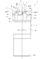
図5から図8は、前述の実施形態で説明した掘削ビット1の変形例を示す。この変形例では、掘削ビット1の排出流路4が、複数の第1流路41の工具径方向の内端部に接続される接続流路45を有する。接続流路45は、ビット本体2の先端面21から工具軸方向の後端側に窪む凹状であり、工具中心軸O上に位置する。接続流路45は、各第1流路41同士を互いに連通させる。
5 to 8 show a modified example of the excavation bit 1 described in the above-described embodiment. In this modification, the discharge flow path 4 of the excavation bit 1 has a connection flow path 45 connected to the inner end portion of the plurality of first flow paths 41 in the tool radial direction. The connection flow path 45 has a concave shape recessed from the tip surface 21 of the bit body 2 toward the rear end side in the tool axis direction, and is located on the tool center axis O. The connection flow path 45 communicates the first flow paths 41 with each other.
またこの変形例では、フェイス座面23aが、工具周方向の一方側つまり工具回転方向Tへ向かうに従い、工具軸方向の後端側に位置する傾斜面である。そして、フェイスチップ3Aのチップ中心軸Cは、工具軸方向の後端側へ向かうに従い、工具周方向のうち工具回転方向Tとは反対側に向けて延びる。
この場合、掘削時にフェイスチップ3Aは、工具回転方向Tへの回転力によりフェイスチップ3Aに作用する曲げ応力を、チップ軸方向への圧縮応力として受け止めて緩和することができる。このため、フェイスチップ3Aの折損等が抑制される。
Further, in this modification, the face seating surface 23a is an inclined surface located on the rear end side in the tool axis direction toward one side in the tool circumferential direction, that is, in the tool rotation direction T. Then, the tip center axis C of the face tip 3A extends toward the rear end side in the tool axis direction and toward the side opposite to the tool rotation direction T in the tool circumferential direction.
In this case, during excavation, the face tip 3A can receive and relax the bending stress acting on the face tip 3A due to the rotational force in the tool rotation direction T as the compressive stress in the tip axial direction. Therefore, breakage of the face chip 3A and the like are suppressed.
またこの変形例では、複数の掘削チップ3のうち、第1流路41の反工具回転方向に隣り合う所定のフェイスチップ3Aのチップ中心軸Cが、工具軸方向の後端側へ向かうに従い、第1流路41から反工具回転方向に離れる。つまり、第1流路41と工具周方向に隣り合う所定の掘削チップ3のチップ中心軸Cは、工具軸方向の後端側へ向かうに従い、工具周方向において第1流路41から離れる。
上記構成を採用することにより、第1流路41と隣り合う所定の掘削チップ3(フェイスチップ3A)と、第1流路41との間の肉厚が大きく確保されて、第1流路41近傍の摩耗による掘削チップ3のビット本体2からの脱落が抑制される。
Further, in this modification, among the plurality of excavation tips 3, the tip center axis C of the predetermined face tip 3A adjacent to the first flow path 41 in the anti-tool rotation direction is directed toward the rear end side in the tool axis direction. It separates from the first flow path 41 in the anti-tool rotation direction. That is, the tip central axis C of the predetermined drilling tip 3 adjacent to the first flow path 41 in the tool circumferential direction separates from the first flow path 41 in the tool circumferential direction toward the rear end side in the tool axis direction.
By adopting the above configuration, a large wall thickness is secured between the predetermined excavation tip 3 (face tip 3A) adjacent to the first flow path 41 and the first flow path 41, and the first flow path 41 is secured. The excavation tip 3 is suppressed from falling off from the bit body 2 due to wear in the vicinity.
なお上記変形例において、排出流路4の第2流路42は、ゲージ座面24a上に位置するほか、フェイス座面23a上の一部(工具径方向の外端部)にも位置していてもよい。
In the above modification, the second flow path 42 of the discharge flow path 4 is located on the gauge seat surface 24a and also on a part (outer end portion in the tool radial direction) on the face seat surface 23a. You may.
また前述の実施形態では、1つのフェイス座面23aに対して、1つのフェイスチップ3Aが配置され、1つのゲージ座面24aに対して、1つのゲージチップ3Bが配置されている例を挙げたが、これに限らない。1つのフェイス座面23aに対して、複数のフェイスチップ3Aが配置されていたり、1つのゲージ座面24aに対して、複数のゲージチップ3Bが配置されていたりしてもよい。
Further, in the above-described embodiment, an example is given in which one face tip 3A is arranged on one face seat surface 23a and one gauge tip 3B is arranged on one gauge seat surface 24a. However, it is not limited to this. A plurality of face chips 3A may be arranged with respect to one face seating surface 23a, or a plurality of gauge chips 3B may be arranged with respect to one gauge seating surface 24a.
また前述の実施形態では、工具周方向の一方側が、工具回転方向Tに相当し、工具周方向の他方側が、反工具回転方向に相当する例を挙げたが、これに限らない。工具周方向の一方側が、反工具回転方向に相当し、工具周方向の他方側が、工具回転方向Tに相当してもよい。
Further, in the above-described embodiment, an example is given in which one side in the tool circumferential direction corresponds to the tool rotation direction T and the other side in the tool circumferential direction corresponds to the anti-tool rotation direction, but the present invention is not limited to this. One side in the tool circumferential direction may correspond to the anti-tool rotation direction, and the other side in the tool circumferential direction may correspond to the tool rotation direction T.
また前述の実施形態では、掘削チップ3がスパイクチップである例を挙げたが、これに限らない。掘削チップ3は、例えば、その先端部が砲弾型とされたいわゆるバリスティックチップ等であってもよい。
また、チップ中心軸Cを含む掘削チップ3の縦断面視において、刃先部3aの曲率半径が、掘削チップ3の外径寸法の1/2未満であると説明したが、例えばチップ中心軸Cに対して傾斜する断面視において、刃先部3aの曲率半径が、掘削チップ3の外径寸法の1/2未満であってもよい。
Further, in the above-described embodiment, the example in which the excavation tip 3 is a spike tip is given, but the present invention is not limited to this. The excavation tip 3 may be, for example, a so-called ballistic tip having a bullet-shaped tip.
Further, it has been explained that the radius of curvature of the cutting edge portion 3a is less than 1/2 of the outer diameter dimension of the drilling tip 3 in the vertical cross-sectional view of the tip 3 including the tip center axis C. On the other hand, the radius of curvature of the cutting edge portion 3a may be less than ½ of the outer diameter dimension of the drilling tip 3 in the cross-sectional view inclined.
本発明は、本発明の趣旨から逸脱しない範囲において、前述の実施形態および変形例等で説明した各構成を組み合わせてもよく、また、構成の付加、省略、置換、その他の変更が可能である。また本発明は、前述した実施形態等によって限定されず、特許請求の範囲によってのみ限定される。
The present invention may be combined with each of the configurations described in the above-described embodiments and modifications, and the configurations can be added, omitted, replaced, or otherwise changed without departing from the spirit of the present invention. .. Further, the present invention is not limited to the above-described embodiments and the like, but is limited only to the scope of claims.