WO2022091720A1 - 情報処理装置、情報処理方法及びプログラム - Google Patents
情報処理装置、情報処理方法及びプログラム Download PDFInfo
- Publication number
- WO2022091720A1 WO2022091720A1 PCT/JP2021/036918 JP2021036918W WO2022091720A1 WO 2022091720 A1 WO2022091720 A1 WO 2022091720A1 JP 2021036918 W JP2021036918 W JP 2021036918W WO 2022091720 A1 WO2022091720 A1 WO 2022091720A1
- Authority
- WO
- WIPO (PCT)
- Prior art keywords
- time
- detection
- abnormality
- acquired
- information processing
- Prior art date
- Legal status (The legal status is an assumption and is not a legal conclusion. Google has not performed a legal analysis and makes no representation as to the accuracy of the status listed.)
- Ceased
Links
Images




Classifications
-
- H—ELECTRICITY
- H04—ELECTRIC COMMUNICATION TECHNIQUE
- H04L—TRANSMISSION OF DIGITAL INFORMATION, e.g. TELEGRAPHIC COMMUNICATION
- H04L63/00—Network architectures or network communication protocols for network security
- H04L63/14—Network architectures or network communication protocols for network security for detecting or protecting against malicious traffic
- H04L63/1408—Network architectures or network communication protocols for network security for detecting or protecting against malicious traffic by monitoring network traffic
- H04L63/1425—Traffic logging, e.g. anomaly detection
-
- G—PHYSICS
- G06—COMPUTING OR CALCULATING; COUNTING
- G06F—ELECTRIC DIGITAL DATA PROCESSING
- G06F21/00—Security arrangements for protecting computers, components thereof, programs or data against unauthorised activity
- G06F21/50—Monitoring users, programs or devices to maintain the integrity of platforms, e.g. of processors, firmware or operating systems
- G06F21/55—Detecting local intrusion or implementing counter-measures
-
- H—ELECTRICITY
- H04—ELECTRIC COMMUNICATION TECHNIQUE
- H04L—TRANSMISSION OF DIGITAL INFORMATION, e.g. TELEGRAPHIC COMMUNICATION
- H04L63/00—Network architectures or network communication protocols for network security
- H04L63/14—Network architectures or network communication protocols for network security for detecting or protecting against malicious traffic
- H04L63/1408—Network architectures or network communication protocols for network security for detecting or protecting against malicious traffic by monitoring network traffic
- H04L63/1416—Event detection, e.g. attack signature detection
Definitions
- This disclosure relates to information processing devices, information processing methods and programs.
- Patent Document 1 discloses an automobile safety system including a cyber watchman installed inside each of a plurality of vehicles and a cyber hub installed outside the vehicle.
- the cyber watchman is connected to the in-vehicle communication network and acquires communication traffic data on the in-vehicle communication network.
- Cyber Hub receives communication traffic data acquired by Cyber Watchman from Cyber Watchman via a communication network such as the Internet.
- the cyber hub can aggregate communication traffic data from a plurality of vehicles and can acquire high-order information on the cyber attack of the vehicle.
- Patent Document 1 does not disclose a method for specifying a section (for example, a time zone) in which an attack on an in-vehicle communication network (hereinafter, also referred to as a network) occurs, and a huge amount of communication traffic data is transferred to the network.
- a section for example, a time zone
- an attack on an in-vehicle communication network hereinafter, also referred to as a network
- the processing load increases.
- the present disclosure provides an information processing device and the like that can reduce the processing load when extracting the section of the attack on the network.
- the information processing apparatus includes an acquisition unit that acquires a detection log related to an abnormality in the network and an abnormality detection time indicated by the detection log from an abnormality detection sensor that detects an abnormality in the network. Based on the detected detection time, the activation time of the attack on the network is determined, and the activation time determination unit that records the determined activation time, and the attack on the network based on the acquired detection log. It is provided with an end time determination unit that determines the estimated end time of the above and records the determined expected end time.
- the information processing method acquires and acquires the detection log related to the abnormality in the network and the abnormality detection time indicated by the detection log from the abnormality detection sensor that detects the abnormality in the network. Based on the detection time, the activation time of the attack on the network is determined, the determined activation time is recorded, and the estimated end time of the attack on the network is determined based on the acquired detection log. The process of recording the determined estimated end time is included.
- the program according to one aspect of the present disclosure is a program for causing a computer to execute the above information processing method.
- the information processing device or the like it is possible to reduce the processing load when extracting the section of the attack on the network.
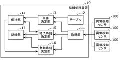
- FIG. 1 is a configuration diagram showing an example of an information processing apparatus according to an embodiment.
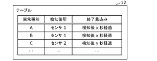
- FIG. 2 is a diagram showing an example of a table in the embodiment.
- FIG. 3 is a flowchart showing an example of an operation at the time of determining the end condition of the information processing apparatus and recording the activation time in the embodiment.
- FIG. 4 is a diagram for explaining the operation at the time of determining the end condition.
- FIG. 5 is a diagram for explaining the operation at the time of recording the activation time.
- FIG. 6 is a diagram for explaining an operation when an end condition is added.
- FIG. 7 is a diagram for explaining the operation at the time of updating the end condition.
- FIG. 8 is a flowchart showing an example of an operation at the time of recording the estimated end time of the information processing apparatus according to the embodiment.
- FIG. 9 is a diagram for explaining the operation at the time of deleting the end condition.
- FIG. 10 is a diagram for explaining the operation at the time of recording the estimated end time.
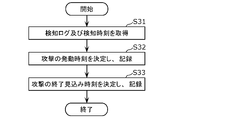
- FIG. 11 is a flowchart showing an example of an information processing method according to another embodiment.
- FIG. 1 is a configuration diagram showing an example of the information processing apparatus 10 according to the embodiment. Note that FIG. 1 also shows an abnormality detection sensor 100 that is communicably connected to the information processing device 10.
- the abnormality detection sensor 100 is a sensor that detects an abnormality in a moving body, which occurs when the moving body is attacked.
- the abnormality detection sensor 100 is a sensor that detects an abnormality in a network that occurs when a network in a mobile body (for example, an in-vehicle network) is attacked.
- the abnormality in the network may be an abnormality in network communication or an abnormality in a device connected to the network (for example, an ECU (Electronic Control Unit) or the like).
- an abnormality in network communication is an abnormality in network traffic, an abnormality in a message ID included in a message flowing through the network (specifically, an abnormality in which the message ID is an unauthorized ID) or a message. Abnormal transmission interval, etc.
- an abnormality of a device connected to a network is an abnormality such as a failure of the device.
- the abnormality detection sensor 100 is, for example, an IDS (Intrusion Detection System) ECU, and is connected to a network or a device connected to the network.
- IDS Intrusion Detection System
- the detection log includes the type of the detected abnormality, the information of the abnormality detection sensor 100 that detected the abnormality, the detection time when the abnormality was detected, and the like.
- a plurality of abnormality detection sensors 100 may be provided, and each of the plurality of abnormality detection sensors 100 may transmit a detection log.
- the detection log may not include the detection time, and the abnormality detection sensor 100 may transmit the detection time to the information processing apparatus 10 as information different from the detection log.
- the moving body is not limited to automobiles, for example, automobiles, but may be mobility such as construction machinery, agricultural machinery, ships, railways, and airplanes.
- the information processing device 10 is a computer that records the activation time and the estimated end time of an attack on the network by processing the detection log transmitted from the abnormality detection sensor 100.
- the information processing device 10 is mounted on a vehicle or the like provided with an abnormality detection sensor 100, and outputs the recorded activation time and expected end time to a server communicably connected to the vehicle or the like.
- the information processing device 10 includes a processor, a memory, a communication interface, and the like.
- the memory is a ROM (Read Only Memory), a RAM (Random Access Memory), or the like, and can store a program executed by the processor.
- the information processing apparatus 10 includes an acquisition unit 11, a table 12, a condition determination unit 13, a holding unit 14, an end time determination unit 15, an activation time determination unit 16, and a recording unit 17.
- the condition determination unit 13, the end time determination unit 15, and the activation time determination unit 16 are realized by a processor or the like that executes a program stored in the memory.
- the acquisition unit 11 is realized by a communication interface.
- the table 12 is stored in the memory.
- the holding unit 14 and the recording unit 17 are realized by a memory.
- the memory in which the program is stored, the memory in which the table 12 is stored, the holding unit 14 and the recording unit 17 may be different memories or one memory.
- the information processing device 10 may be a server connected so as to be able to communicate with a vehicle or the like provided with the abnormality detection sensor 100. Further, the components constituting the information processing apparatus 10 may be distributed and arranged on a plurality of servers, and the information processing apparatus 10 may be an information processing system.
- the acquisition unit 11 acquires the detection log related to the abnormality in the network and the abnormality detection time indicated by the detection log from the abnormality detection sensor 100 that detects the abnormality in the network. For example, the acquisition unit 11 acquires the detection log from the abnormality detection sensor 100 and acquires the detection time included in the detection log.
- Table 12 is a table in which the type of anomaly and the prospect of the end of the attack on the network when the anomaly occurs are associated in advance. The table 12 will be described with reference to FIG.
- FIG. 2 is a diagram showing an example of the table 12 in the embodiment.
- the type of abnormality, the detection location indicating the abnormality detection sensor 100 that detected the abnormality, and the prospect of the end of the attack on the network when the abnormality occurs are associated in advance.
- the type A abnormality is an abnormality detected by the sensor 1, and it is expected that the attack on the network will end x seconds after the detection.
- the type B abnormality is an abnormality detected by the sensor 1, and it is expected that the attack on the network will end x seconds after the detection.
- the type C abnormality is an abnormality detected by the sensor 2, and it is expected that the attack on the network will end when y seconds have elapsed after the detection.
- the senor 1 is an abnormality detection sensor 100 that monitors network communication
- an abnormality of type A is an abnormality of the communication amount of the network
- an abnormality of type B is an abnormality of a message flowing through the network.
- the sensor 2 is an abnormality detection sensor 100 that monitors a device connected to a network
- an abnormality of type C is an abnormality such as a failure of the device.
- Such a table 12 is used to determine an expected termination condition (hereinafter, also referred to as an termination condition) for an attack on the network.
- the condition determination unit 13 determines the end condition of the attack on the network based on the detection log acquired by the acquisition unit 11. The details of the operation of the condition determination unit 13 will be described later.
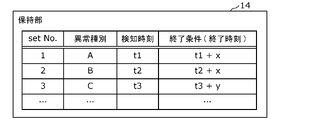
- the holding unit 14 holds the end condition determined by the condition determining unit 13.
- Various types of anomalies may occur due to an attack on the network.
- One anomaly detection sensor 100 generates a detection log for each anomaly that occurs, and the acquisition unit 11 detects a plurality of detection logs as one anomaly. It can be obtained from the sensor 100.
- a plurality of abnormality detection sensors 100 may detect an abnormality due to an attack on the network, and the acquisition unit 11 may acquire a plurality of detection logs from the plurality of abnormality detection sensors 100.
- the holding unit 14 can hold the end condition for each acquired detection log. That is, the holding unit 14 can hold a plurality of termination conditions.
- the end time determination unit 15 determines the estimated end time of the attack on the network based on the detection log acquired by the acquisition unit 11, and records the determined end time in the recording unit 17. The details of the operation of the end time determination unit 15 will be described later.
- the activation time determination unit 16 determines the activation time of an attack on the network based on the detection time acquired by the acquisition unit 11, and records the determined activation time in the recording unit 17. The details of the operation of the activation time determination unit 16 will be described later.
- the recording unit 17 records the activation time of the attack on the network determined by the activation time determination unit 16, and records the estimated end time of the attack on the network determined by the end time determination unit 15.
- the recorded activation time and expected end time are output to a device (server or the like) connected to the information processing apparatus 10 and used for attack analysis.
- FIG. 3 is a flowchart showing an example of the operation at the time of determining the end condition of the information processing apparatus 10 and recording the activation time in the embodiment.
- condition determination unit 13 determines whether or not the acquisition unit 11 has acquired the detection log (step S11). If the acquisition unit 11 has not acquired the detection log (No in step S11), the condition determination unit 13 repeats the process in step S11 until the acquisition unit 11 acquires the detection log.
- the condition determination unit 13 determines the end condition of the attack on the network based on the acquired detection log (step S12). The operation of the condition determination unit 13 at the time of determining the end condition will be described with reference to FIG.
- FIG. 4 is a diagram for explaining the operation at the time of determining the end condition.
- the termination conditions of an attack on the network may differ depending on the type of abnormality indicated by the detection log, and as shown in Table 12, the expected termination can be predetermined for each type of abnormality. Therefore, the condition determination unit 13 can determine the end condition based on the type of abnormality and the table 12 indicated by the detection log acquired by the acquisition unit 11. Specifically, the condition determination unit 13 collates the detection log acquired by the acquisition unit 11 with the table 12, and determines the termination condition of the attack on the network that caused the abnormality indicated by the detection log. As shown in FIG. 4, it is assumed that the abnormality detection sensor 100 detects the abnormality of the type A at the time t1, and the acquisition unit 11 acquires the detection log related to the abnormality of the type A and the detection time t1 of the abnormality.
- the condition determination unit 13 adds x seconds to the detection time t1 to time t1 + x. Is determined as the termination condition of the attack on the network that caused the abnormality indicated by the detection log acquired by the acquisition unit 11.
- the conditions for ending an attack on the network may differ depending on the parameters included in the detection log. For example, as a parameter included in the detection log, it may be better to make the end condition different depending on whether the network traffic is large or small.
- the condition determination unit 13 tightens the end condition when the communication volume of the network is large (for example, determines the end condition so that the expected end time is delayed). In this way, the condition determination unit 13 may determine the end condition based on the parameters included in the acquired detection log.
- the conditions for ending an attack on the network may differ depending on the acquisition status of other detection logs when the detection log is acquired. For example, when the detection log is acquired, if another detection log indicating that an error has occurred in the device connected to the network has already been acquired, such other detection log has been acquired. It may be better to have different termination conditions than when there is none.
- the condition determination unit 13 tightens the end condition (for example, the estimated end time is delayed) when another detection log indicating that an abnormality has occurred in the device connected to the network has already been acquired. Determine such termination conditions). In this way, the condition determination unit 13 may determine the end condition based on the acquisition status of other detection logs when the detection log is acquired.
- the activation time determination unit 16 determines whether or not the end condition is held in the holding unit 14 (step S13).
- the activation time determination unit 16 detects an abnormality indicated by the detection log acquired in a state where the end condition is not held in the holding unit 14 (No in step S13) and the end condition is not held in the holding unit 14. The time is determined as the activation time and recorded in the recording unit 17 (step S14). The operation of the activation time determination unit 16 at the time of recording the activation time will be described with reference to FIG.
- FIG. 5 is a diagram for explaining the operation at the time of recording the activation time.
- the abnormality detection sensor 100 detects the abnormality of the type A at the time t1, and the acquisition unit 11 acquires the detection log related to the abnormality of the type A and the detection time t1 of the abnormality. Since the holding unit 14 does not hold the end condition, the activation time determining unit 16 activates the abnormality detection time t1 indicated by the detection log acquired in the state where the holding unit 14 does not hold the end condition. It is determined as a time and recorded in the recording unit 17. Since the state in which the end condition is not held in the holding unit 14, the network is not attacked, the abnormality detection time indicated by the detection log acquired in that state is used as the network attack activation time. Can be decided.
- the condition determination unit 13 writes the end condition determined in step S12 in the holding unit 14 (step S15). As a result, the end condition is held in the holding unit 14. Although the details will be described later, the end condition held by the holding unit 14 is deleted when it is satisfied.
- step S13 when the end condition is held in the holding unit 14 (Yes in step S13), in other words, after the end condition is written in the holding unit 14 in step S15 and before the end condition is satisfied (that is,). If a new detection log is acquired in step S11 (before the termination condition is deleted), the condition determination unit 13 updates the retained termination condition based on the acquired new detection log, or updates the retained termination condition. , A new termination condition is added to the holding unit 14 (step S16). The operation of the condition determination unit 13 when a new end condition is added will be described with reference to FIG. 6, and the operation of the condition determination unit 13 when the end condition is updated will be described with reference to FIG. 7.
- FIG. 6 is a diagram for explaining the operation when the end condition is added.
- the abnormality detection sensor 100 detects an abnormality of type A at time t1 and the end condition (end time) t1 + x is held by the holding unit 14.
- the abnormality detection sensor 100 detects an abnormality of type B at time t2, and a new detection log is acquired before the end condition t1 + x held in the holding unit 14 is satisfied.
- the condition determination unit 13 determines a new end condition t2 + x based on the acquired new detection log (specifically, by collating the new detection log with the table 12), and the holding unit A new end condition t2 + x is added to 14.
- the condition determination unit 13 determines a new end condition t3 + y based on the acquired new detection log (specifically, by collating the new detection log with the table 12), and the holding unit A new end condition t3 + y is added to 14.
- FIG. 7 is a diagram for explaining the operation at the time of updating the end condition.
- the holding unit 14 already holds the end condition t1 + x for the type A abnormality, the end condition t2 + x for the type B abnormality, and the end condition t3 + y for the type C abnormality.
- the abnormality detection sensor 100 detects an abnormality of type A at time t4, and a new detection log is acquired before each end condition held in the holding unit 14 is satisfied.
- the condition determination unit 13 determines a new end condition t4 + x based on the acquired new detection log (specifically, by collating the new detection log with the table 12).
- the condition determining unit 13 updates the end condition t1 + x held in the holding unit 14 to the end condition t4 + x. ..
- FIG. 8 is a flowchart showing an example of an operation at the time of recording the estimated end time of the information processing apparatus 10 according to the embodiment. The operation shown in FIG. 3 and the operation shown in FIG. 8 are performed in parallel.
- the end time determination unit 15 determines whether or not the end condition held by the holding unit 14 is satisfied (step S21). If the end condition held in the holding unit 14 is not satisfied (No in step S21), the end time determining unit 15 repeats the process in step S21 until the end condition held in the holding unit 14 is satisfied. ..
- the end time determining unit 15 deletes the satisfied end condition from the holding unit 14 (step S22).
- the operation of the end time determination unit 15 when the satisfied end condition is deleted will be described with reference to FIG.
- FIG. 9 is a diagram for explaining the operation when the end condition is deleted.
- the holding unit 14 already holds the end condition t1 + x for the type A abnormality, the end condition t2 + x for the type B abnormality, and the end condition t3 + y for the type C abnormality.
- the end time determination unit 15 deletes the satisfied end condition t1 + x from the holding unit 14.
- the end time determination unit 15 determines whether or not the end condition is held in the holding unit 14 (step S23). As shown in the lower right of FIG. 9, when the end condition is held in the holding unit 14 (Yes in step S23), the end condition held in the holding unit 14 is processed in steps S21 and S22. Is performed, and the processes from step S21 to step S23 are repeated until the end condition is not held in the holding unit 14.
- the end time determination unit 15 does not hold the end condition in the holding unit 14 (No in step S23)
- the end time determination unit 15 is finally satisfied (in other words, finally) among the end conditions held in the holding unit 14.
- the time when the (deleted) end condition is satisfied is determined as the expected end time, and the determined expected end time is recorded in the recording unit 17 (step S24). The operation of the end time determination unit 15 at the time of recording the expected end time will be described with reference to FIG.
- FIG. 10 is a diagram for explaining the operation at the time of recording the estimated end time.
- the holding unit 14 holds the end condition t4 + x for the abnormality of the type A.
- the end time determination unit 15 deletes the satisfied end condition t4 + x from the holding unit 14.
- the holding unit 14 is in a state where the end condition is not held, and the end time determining unit 15 is expected to end the time t4 + x when the last satisfied end condition t4 + x is satisfied. It is determined as a time, and the estimated end time t4 + x is recorded in the recording unit 17.
- the end time determination unit 15 determines the time when the held end condition is satisfied as the expected end time. Specifically, when a plurality of end conditions are held in the holding unit 14, the end time determining unit 15 satisfies the time when the last deleted end condition is satisfied, in other words, each of the plurality of end conditions is satisfied. The latest time is determined as the expected end time. If one end condition is held from the state where the end condition is not held in the holding unit 14, and then a new detection log is not acquired before the one end condition is satisfied, the end time determination unit 15 determines the time at which the one held end condition is satisfied as the expected end time, and records it in the recording unit 17.
- the time when the end condition is satisfied may be the time when a predetermined time has elapsed since the detection log was acquired, or a counter that counts up after the detection log is acquired is predetermined. It may be the time when the threshold value is exceeded, or it may be the time when a predetermined detection log is acquired.
- the predetermined time is determined according to the type of abnormality and the like.
- a predetermined threshold value is determined according to the type of abnormality and the count-up cycle of the counter.
- the predetermined detection log is a detection log indicating normality that is periodically transmitted when the abnormality detection sensor 100 does not detect an abnormality
- the end time determination unit 15 has a predetermined number of detection logs indicating normality.
- the time when it is acquired may be determined as the estimated end time.
- the information processing apparatus 10 has an abnormality detection sensor 100 that detects an abnormality in the network, a detection log related to the abnormality in the network, an acquisition unit 11 that acquires an abnormality detection time indicated by the detection log, and an acquired detection time. Based on this, the activation time of the attack on the network is determined, the activation time determination unit 16 that records the determined activation time, and the estimated end time of the attack on the network is determined and determined based on the acquired detection log. The end time determination unit 15 for recording the expected end time is provided.
- the detection log and the detection time acquired from the abnormality detection sensor 100 are used to automatically record the activation time of the attack on the network and the estimated end time of the attack on the network.
- the section of the attack on the network can be easily extracted from the time and the estimated end time. Therefore, it is possible to reduce the processing load when extracting the section of the attack on the network.
- the information processing apparatus 10 further includes a condition determination unit 13 that determines the end condition of an attack on the network based on the acquired detection log, and a holding unit 14 that holds the determined end condition.
- the end time determination unit 15 may determine the time when the held end condition is satisfied as the expected end time.
- the conditions for terminating an attack on the network that caused the anomaly may differ depending on the type of anomaly indicated by the detection log. Therefore, the end condition is determined based on the acquired detection log, and the time when the end condition is satisfied is determined as the expected end time, so that the expected end time according to the type indicated by the acquired detection log is determined. be able to.
- condition determination unit 13 further updates the retained end condition based on the acquired new detection log.
- a new termination condition may be added to the holding unit 14.
- the abnormality detection sensor 100 shows the detection log corresponding to the termination condition before the termination condition already held in the holding unit 14 is satisfied. Anomalies of the same type as the anomaly may be detected again, or anomalies of a different type may be detected. Therefore, when the abnormality detection sensor 100 detects an abnormality of the same type as the abnormality indicated by the detection log corresponding to the end condition already held in the holding unit 14, the holding unit 14 receives the abnormality based on the new detection log related to the abnormality. The retained termination condition is updated.
- the holding unit 14 responds to a new detection log related to the abnormality. New termination conditions are added.
- the holding unit 14 can manage the termination conditions for one or more abnormalities generated by the attack.
- the end time determining unit 15 may determine the latest time among the times when each of the plurality of end conditions is satisfied as the expected end time.
- the end time determination unit 15 may further delete the satisfied end condition from the holding unit 14.
- the end conditions that are satisfied are deleted in order, so that the time when the last deleted end condition is satisfied (that is, each of the plurality of end conditions).
- the latest time among the times that hold can be determined as the expected end time. Further, since a new attack may be made in the future, the termination condition corresponding to this attack can be removed from the holding unit 14 in preparation for the new attack.
- the activation time determination unit 16 may determine the detection time of an abnormality indicated by the detection log acquired in a state where the holding unit 14 does not hold the end condition as the activation time.
- the state in which the end condition is not held in the holding unit 14 is the state in which the network is not attacked
- the abnormality detection time indicated by the detection log acquired in that state is set to the network. It can be determined as the time when the attack is triggered.
- condition determination unit 13 is based on the type of abnormality indicated by the acquired detection log, the parameters included in the acquired detection log, or the acquisition status of other detection logs when the detection log is acquired.
- the termination condition may be determined.
- the conditions for ending an attack on the network may differ depending on the type of abnormality indicated by the detection log. Therefore, the end condition can be determined based on the type of abnormality indicated by the detection log. Further, for example, the conditions for terminating an attack on the network may differ depending on the parameters included in the detection log. Therefore, the end condition can be determined based on the parameters included in the detection log. Further, for example, the termination conditions of an attack on the network may differ depending on the acquisition status of other detection logs when the detection log is acquired. Therefore, the end condition can be determined based on the acquisition status of other detection logs when the detection log is acquired.
- the time when the end condition is satisfied is the time when a predetermined time has elapsed since the detection log was acquired, or when the counter that counts up after the detection log is acquired exceeds a predetermined threshold value. Or the time when a predetermined detection log is acquired.
- the information processing apparatus 10 may output an instruction according to the recorded activation time and expected end time, or the recorded activation time and expected end time.
- the information processing apparatus 10 outputs the activation time and the estimated end time recorded in a device (server or the like) connected to the information processing apparatus 10, and the apparatus concerned outputs the output activation time and the estimated end time.
- the section (duration) in which a cyber attack occurs can be derived or specified with a small processing load.
- the information processing apparatus 10 gives the information processing apparatus 10 an instruction to derive or specify a cyber attack occurrence section according to, for example, the activation time and the estimated end time, as an instruction according to the recorded activation time and the estimated end time.
- the device can derive or specify the section where the cyber attack occurs with a small processing load.
- the end condition may not be determined based on the acquired detection log, and the predetermined end condition may be held in the holding unit 14.
- the present disclosure can be realized not only as an information processing apparatus 10, but also as an information processing method including steps (processing) performed by each component constituting the information processing apparatus 10.
- FIG. 11 is a flowchart showing an example of an information processing method in another embodiment.
- the information processing method acquires a detection log related to an abnormality in the network and an abnormality detection time indicated by the detection log from the abnormality detection sensor 100 that detects an abnormality in the network (step S31).
- the activation time of the attack on the network is determined based on the acquired detection time, the determined activation time is recorded (step S32), and the estimated end time of the attack on the network is determined based on the acquired detection log. Is included, and a process of recording the determined estimated end time (step S33) is included.
- a step in an information processing method may be executed by a computer (computer system). Then, the present disclosure can be realized as a program for causing a computer to execute the steps included in the information processing method.
- the present disclosure can be realized as a non-temporary computer-readable recording medium such as a CD-ROM in which the program is recorded.
- each step is executed by executing the program using hardware resources such as a computer CPU, memory, and input / output circuit. .. That is, each step is executed by the CPU acquiring data from the memory or the input / output circuit or the like and performing an operation, or outputting the operation result to the memory or the input / output circuit or the like.
- hardware resources such as a computer CPU, memory, and input / output circuit. .. That is, each step is executed by the CPU acquiring data from the memory or the input / output circuit or the like and performing an operation, or outputting the operation result to the memory or the input / output circuit or the like.
- each component included in the information processing apparatus 10 of the above embodiment may be realized as a dedicated or general-purpose circuit.
- each component included in the information processing apparatus 10 of the above embodiment may be realized as an LSI (Large Scale Integration) which is an integrated circuit (IC: Integrated Circuit).
- LSI Large Scale Integration
- IC integrated circuit
- the integrated circuit is not limited to the LSI, and may be realized by a dedicated circuit or a general-purpose processor.
- a programmable FPGA (Field Programmable Gate Array) or a reconfigurable processor in which the connection and settings of circuit cells inside the LSI can be reconfigured may be used.
- This disclosure can be applied to, for example, a device for monitoring an in-vehicle network or the like.
Landscapes
- Engineering & Computer Science (AREA)
- Computer Security & Cryptography (AREA)
- Computer Hardware Design (AREA)
- General Engineering & Computer Science (AREA)
- Computing Systems (AREA)
- Computer Networks & Wireless Communication (AREA)
- Signal Processing (AREA)
- Software Systems (AREA)
- Theoretical Computer Science (AREA)
- Physics & Mathematics (AREA)
- General Physics & Mathematics (AREA)
- Data Exchanges In Wide-Area Networks (AREA)
Priority Applications (3)
| Application Number | Priority Date | Filing Date | Title |
|---|---|---|---|
| JP2022558957A JP7291909B2 (ja) | 2020-10-26 | 2021-10-06 | 情報処理装置、情報処理方法及びプログラム |
| DE112021005651.4T DE112021005651B4 (de) | 2020-10-26 | 2021-10-06 | Informationsverarbeitungsvorrichtung, Informationsverarbeitungsverfahren und Programm |
| US18/137,168 US11765191B2 (en) | 2020-10-26 | 2023-04-20 | Information processing device and information processing method |
Applications Claiming Priority (2)
| Application Number | Priority Date | Filing Date | Title |
|---|---|---|---|
| JP2020-179027 | 2020-10-26 | ||
| JP2020179027 | 2020-10-26 |
Related Child Applications (1)
| Application Number | Title | Priority Date | Filing Date |
|---|---|---|---|
| US18/137,168 Continuation US11765191B2 (en) | 2020-10-26 | 2023-04-20 | Information processing device and information processing method |
Publications (1)
| Publication Number | Publication Date |
|---|---|
| WO2022091720A1 true WO2022091720A1 (ja) | 2022-05-05 |
Family
ID=81382378
Family Applications (1)
| Application Number | Title | Priority Date | Filing Date |
|---|---|---|---|
| PCT/JP2021/036918 Ceased WO2022091720A1 (ja) | 2020-10-26 | 2021-10-06 | 情報処理装置、情報処理方法及びプログラム |
Country Status (4)
| Country | Link |
|---|---|
| US (1) | US11765191B2 (https=) |
| JP (1) | JP7291909B2 (https=) |
| DE (1) | DE112021005651B4 (https=) |
| WO (1) | WO2022091720A1 (https=) |
Cited By (1)
| Publication number | Priority date | Publication date | Assignee | Title |
|---|---|---|---|---|
| US20230153729A1 (en) * | 2021-10-28 | 2023-05-18 | RiskLens, Inc. | Method and apparatus for determining effectiveness of cybersecurity risk controls |
Families Citing this family (3)
| Publication number | Priority date | Publication date | Assignee | Title |
|---|---|---|---|---|
| JP7517223B2 (ja) * | 2021-03-29 | 2024-07-17 | 株式会社デンソー | 攻撃分析装置、攻撃分析方法、及び攻撃分析プログラム |
| CN115412363B (zh) * | 2022-09-13 | 2024-06-28 | 杭州迪普科技股份有限公司 | 异常流量日志处理方法和装置 |
| JP2024041334A (ja) * | 2022-09-14 | 2024-03-27 | 株式会社デンソー | 攻撃分析装置、攻撃分析方法、及び攻撃分析プログラム |
Citations (1)
| Publication number | Priority date | Publication date | Assignee | Title |
|---|---|---|---|---|
| JP2004046742A (ja) * | 2002-07-15 | 2004-02-12 | Ntt Data Corp | 攻撃分析装置、センサ、攻撃分析方法及びプログラム |
Family Cites Families (10)
| Publication number | Priority date | Publication date | Assignee | Title |
|---|---|---|---|---|
| JPS6382724U (https=) | 1986-11-18 | 1988-05-31 | ||
| US10649449B2 (en) * | 2013-03-04 | 2020-05-12 | Fisher-Rosemount Systems, Inc. | Distributed industrial performance monitoring and analytics |
| US9840212B2 (en) * | 2014-01-06 | 2017-12-12 | Argus Cyber Security Ltd. | Bus watchman |
| US10708293B2 (en) * | 2015-06-29 | 2020-07-07 | Argus Cyber Security Ltd. | System and method for time based anomaly detection in an in-vehicle communication network |
| US10798114B2 (en) * | 2015-06-29 | 2020-10-06 | Argus Cyber Security Ltd. | System and method for consistency based anomaly detection in an in-vehicle communication network |
| JP6555559B1 (ja) | 2018-06-15 | 2019-08-07 | パナソニックIpマネジメント株式会社 | 電子制御装置、監視方法、プログラム及びゲートウェイ装置 |
| JP7149888B2 (ja) * | 2018-10-17 | 2022-10-07 | パナソニック インテレクチュアル プロパティ コーポレーション オブ アメリカ | 情報処理装置、情報処理方法及びプログラム |
| WO2020079896A1 (ja) | 2018-10-17 | 2020-04-23 | パナソニック インテレクチュアル プロパティ コーポレーション オブ アメリカ | 情報処理装置、情報処理方法及びプログラム |
| JP7322806B2 (ja) * | 2020-05-15 | 2023-08-08 | トヨタ自動車株式会社 | 車両用異常検出装置 |
| JP7392586B2 (ja) * | 2020-06-17 | 2023-12-06 | 株式会社デンソー | ログ送信制御装置 |
-
2021
- 2021-10-06 JP JP2022558957A patent/JP7291909B2/ja active Active
- 2021-10-06 DE DE112021005651.4T patent/DE112021005651B4/de active Active
- 2021-10-06 WO PCT/JP2021/036918 patent/WO2022091720A1/ja not_active Ceased
-
2023
- 2023-04-20 US US18/137,168 patent/US11765191B2/en active Active
Patent Citations (1)
| Publication number | Priority date | Publication date | Assignee | Title |
|---|---|---|---|---|
| JP2004046742A (ja) * | 2002-07-15 | 2004-02-12 | Ntt Data Corp | 攻撃分析装置、センサ、攻撃分析方法及びプログラム |
Cited By (2)
| Publication number | Priority date | Publication date | Assignee | Title |
|---|---|---|---|---|
| US20230153729A1 (en) * | 2021-10-28 | 2023-05-18 | RiskLens, Inc. | Method and apparatus for determining effectiveness of cybersecurity risk controls |
| US12367441B2 (en) * | 2021-10-28 | 2025-07-22 | Risklens, Llc | Method and apparatus for determining effectiveness of cybersecurity risk controls |
Also Published As
| Publication number | Publication date |
|---|---|
| JP7291909B2 (ja) | 2023-06-16 |
| DE112021005651B4 (de) | 2024-04-25 |
| US11765191B2 (en) | 2023-09-19 |
| DE112021005651T5 (de) | 2023-09-21 |
| US20230262080A1 (en) | 2023-08-17 |
| JPWO2022091720A1 (https=) | 2022-05-05 |
Similar Documents
| Publication | Publication Date | Title |
|---|---|---|
| WO2022091720A1 (ja) | 情報処理装置、情報処理方法及びプログラム | |
| US11277427B2 (en) | System and method for time based anomaly detection in an in-vehicle communication | |
| US10298612B2 (en) | System and method for time based anomaly detection in an in-vehicle communication network | |
| JP6173541B2 (ja) | セキュリティ装置、攻撃検知方法及びプログラム | |
| US11924225B2 (en) | Information processing apparatus, information processing method, and recording medium | |
| JP7296555B2 (ja) | 異常検知装置、異常検知方法及びプログラム | |
| CN111371623B (zh) | 业务性能和安全的监测方法、装置、存储介质及电子设备 | |
| CN110546921A (zh) | 不正当检测方法、不正当检测装置以及程序 | |
| JP7286326B2 (ja) | 情報処理装置及び情報処理方法 | |
| CN113676441B (zh) | 车辆用异常检测装置及车辆用异常检测方法 | |
| US12375511B2 (en) | Attack path generation method and attack path generation device | |
| CN119520247A (zh) | 故障根因定位方法、装置和相关产品 | |
| JP7523855B2 (ja) | 検知ルール出力方法、及び、セキュリティシステム | |
| JPWO2023112493A5 (https=) | ||
| US11474889B2 (en) | Log transmission controller | |
| JP7346688B2 (ja) | 情報処理装置、情報処理方法及びプログラム | |
| JP2023128289A (ja) | 監視装置、監視システムおよび監視方法 | |
| JP2024051327A (ja) | 更新装置、更新方法、及び更新プログラム | |
| JP7439668B2 (ja) | ログ送信制御装置 | |
| US10743157B2 (en) | Method for managing modules incorporated into a plurality of vehicles, managing device and managing server using the same | |
| CN120256235A (zh) | 服务集群的检测方法、装置及电子设备 | |
| CN118353918A (zh) | 车辆数据采集处理方法、装置、终端及存储介质 | |
| CN120179440A (zh) | 日志数据处理方法、装置、设备,及计算机介质 | |
| CN118694785A (zh) | 一种日志处理方法、装置、设备以及存储介质 | |
| JP2022172456A (ja) | 車両の電子データシステムへの侵入の検知/評価 |
Legal Events
| Date | Code | Title | Description |
|---|---|---|---|
| 121 | Ep: the epo has been informed by wipo that ep was designated in this application |
Ref document number: 21885839 Country of ref document: EP Kind code of ref document: A1 |
|
| ENP | Entry into the national phase |
Ref document number: 2022558957 Country of ref document: JP Kind code of ref document: A |
|
| WWE | Wipo information: entry into national phase |
Ref document number: 112021005651 Country of ref document: DE |
|
| 122 | Ep: pct application non-entry in european phase |
Ref document number: 21885839 Country of ref document: EP Kind code of ref document: A1 |