WO2022091384A1 - Wave gear device provided with three-dimensional tooth profile - Google Patents
Wave gear device provided with three-dimensional tooth profile Download PDFInfo
- Publication number
- WO2022091384A1 WO2022091384A1 PCT/JP2020/040965 JP2020040965W WO2022091384A1 WO 2022091384 A1 WO2022091384 A1 WO 2022091384A1 JP 2020040965 W JP2020040965 W JP 2020040965W WO 2022091384 A1 WO2022091384 A1 WO 2022091384A1
- Authority
- WO
- WIPO (PCT)
- Prior art keywords
- tooth
- internal
- external
- profile
- gear
- Prior art date
Links
Images


Classifications
-
- F—MECHANICAL ENGINEERING; LIGHTING; HEATING; WEAPONS; BLASTING
- F16—ENGINEERING ELEMENTS AND UNITS; GENERAL MEASURES FOR PRODUCING AND MAINTAINING EFFECTIVE FUNCTIONING OF MACHINES OR INSTALLATIONS; THERMAL INSULATION IN GENERAL
- F16H—GEARING
- F16H49/00—Other gearings
- F16H49/001—Wave gearings, e.g. harmonic drive transmissions
-
- F—MECHANICAL ENGINEERING; LIGHTING; HEATING; WEAPONS; BLASTING
- F16—ENGINEERING ELEMENTS AND UNITS; GENERAL MEASURES FOR PRODUCING AND MAINTAINING EFFECTIVE FUNCTIONING OF MACHINES OR INSTALLATIONS; THERMAL INSULATION IN GENERAL
- F16H—GEARING
- F16H55/00—Elements with teeth or friction surfaces for conveying motion; Worms, pulleys or sheaves for gearing mechanisms
- F16H55/02—Toothed members; Worms
- F16H55/08—Profiling
- F16H55/0833—Flexible toothed member, e.g. harmonic drive
-
- F—MECHANICAL ENGINEERING; LIGHTING; HEATING; WEAPONS; BLASTING
- F16—ENGINEERING ELEMENTS AND UNITS; GENERAL MEASURES FOR PRODUCING AND MAINTAINING EFFECTIVE FUNCTIONING OF MACHINES OR INSTALLATIONS; THERMAL INSULATION IN GENERAL
- F16H—GEARING
- F16H55/00—Elements with teeth or friction surfaces for conveying motion; Worms, pulleys or sheaves for gearing mechanisms
- F16H55/02—Toothed members; Worms
- F16H55/08—Profiling
- F16H55/084—Non-circular rigid toothed member, e.g. elliptic gear
-
- F—MECHANICAL ENGINEERING; LIGHTING; HEATING; WEAPONS; BLASTING
- F16—ENGINEERING ELEMENTS AND UNITS; GENERAL MEASURES FOR PRODUCING AND MAINTAINING EFFECTIVE FUNCTIONING OF MACHINES OR INSTALLATIONS; THERMAL INSULATION IN GENERAL
- F16H—GEARING
- F16H49/00—Other gearings
- F16H49/001—Wave gearings, e.g. harmonic drive transmissions
- F16H2049/003—Features of the flexsplines therefor
Definitions
- the present invention relates to a cup type or top hat type wave gear device. More specifically, the present invention relates to a wave gear device having a three-dimensional tooth profile capable of forming a three-dimensional meshing state in which the internal gear and the external gear mesh at each position in the tooth muscle direction.
- Cup-type or top-hat-type wave gearing devices include rigid internal gears, cup-shaped or top-hat-shaped flexible external gears coaxially arranged inside the gears, and waves fitted inside the gears.
- the external gears are formed on a flexible cylindrical body, a diaphragm extending radially from the rear end of the cylindrical body, and an outer peripheral surface portion on the open end side of the cylindrical body. It has teeth.
- the external gear is elliptical flexed by a wave generator and meshes with the internal gear at both ends of the ellipse in the major axis direction.
- a commonly used strain wave gearing includes a rigid internal gear, a flexible external gear, and a wave generator that bends the external gear into an elliptical shape and engages the internal gear. ing. Each tooth of the external gear is repeatedly bent in the radial direction by a wave generator with a constant amplitude, and the meshing state and the meshing disengagement state with respect to the internal gear are repeated.
- the motion trajectory of the meshing of the external gear with respect to the internal gear can be shown by a rack approximation. For example, in FIG. 7 of Patent Document 2 (International Publication No.
- the external gear is in a moving state (from the deepest meshing state to the deepest meshing state) with respect to the internal gear from the disengaged state to the deepest meshing state.
- the state of movement up to the state of withdrawal) is shown.
- the meshing state of the internal gear with respect to the internal teeth also differs. Even if an external tooth profile that can form a continuous meshing state with respect to the internal tooth is set on a cross section perpendicular to the axis of one position in the direction of the tooth muscle in the external tooth, proper meshing is performed at another position in the direction of the tooth muscle. No state is formed.
- Patent Document 3 Japanese Unexamined Patent Publication No. 2017-445287
- the tooth profile of the internal gear is the same tooth profile at each position in the tooth muscle direction
- the external tooth profile is a straight tooth profile
- the tooth surfaces on both sides thereof are defined.
- the inclined surface is inclined so that the tooth thickness gradually increases from the end on the diaphragm side toward the end on the open end side of the external gear along the tooth muscle direction. This prevents the tooth tip on the diaphragm side of the external tooth from interfering with the tooth tip of the internal tooth in the meshing operation between the external tooth and the internal tooth.
- an internal gear is based on the movement locus of a flexible external gear tooth with respect to a rigid internal gear tooth.
- the basic tooth profile of the teeth and external teeth is set.
- the tooth profile of the internal gear has the same basic internal tooth profile at each position in the direction of the tooth muscle.
- the diameter of the tip circle gradually decreases from the opening end side to the diaphragm side in the tooth muscle direction by dislocating both sides of the external tooth basic tooth profile in the tooth muscle direction.
- Patent Document 5 International Publication No. 2019/0777719
- the tooth profile of the internal teeth of a rigid internal gear is the same at each position in the tooth muscle direction. ..
- the tooth profile of the external teeth of the flexible external gear is set as follows.
- the tooth tip thickness of the external tooth gradually decreases from the external tooth outer end on the side of the open end of the external tooth gear toward the external tooth inner end on the diaphragm side of the external tooth gear along the tooth muscle direction.
- the pressure angle at the pitch point of the external tooth gradually increases from the outer end of the external tooth to the inner end of the external tooth along the direction of the tooth muscle.
- the tooth profile of the external tooth By making the tooth profile of the external tooth a three-dimensional tooth profile that changes along the tooth muscle direction, not only the state of the two-dimensional meshing in which the meshing is formed on one axis perpendicular cross section in the tooth muscle direction, but also the tooth. It forms a three-dimensional meshing state in which the external teeth engage with the internal teeth in a wide range along the muscle direction.
- the tooth profile of the internal gear has the same tooth profile along the tooth muscle, and the external teeth of the external gear have teeth. It is a three-dimensional tooth profile in which the tooth profile shape is changed along the muscle.
- an object of the present invention is to provide a three-dimensional tooth profile that can easily realize three-dimensional meshing over the entire tooth muscle direction without causing interference and that is easy to perform gear cutting, for external teeth and internal teeth. It is an object of the present invention to provide a strain wave gearing adopted for a tooth profile of a tooth.
- the present invention presents a cup-shaped or silk-hat-shaped wave gear equipped with a rigid internal tooth gear, a cup-shaped or silk-hat-shaped flexible external tooth gear, and a wave generator.
- the cross section when the external tooth gear is cut at a predetermined position in the tooth muscle direction of the external tooth gear on an orthogonal plane orthogonal to the tooth muscle direction is used as a reference cross section, and the external tooth in the tooth muscle direction of the internal tooth of the internal tooth gear is used as a reference cross section.
- the end corresponding to the outer end is the outer end of the inner tooth and the other end is the inner end of the inner tooth
- the outer tooth and the inner tooth are set to a three-dimensional tooth profile as follows.
- the tooth profile contour shape of the external tooth on the reference cross section is the basic external tooth profile, and the tooth profile contour shape of the internal tooth at the cross-sectional position of the internal tooth corresponding to the reference cross section is set to be meshable with the basic external tooth profile. It is a tooth profile. Further, the contour of the internal tooth profile at each position in the tooth muscle direction of the internal tooth is obtained by proportionally reducing the basic internal tooth profile only in the tooth thickness direction at a magnification corresponding to the amount of bending of the external tooth at each position. It is a proportionally reduced tooth profile.
- the external tooth has a tapered tooth profile in which the root circle gradually increases from the outer end of the external tooth to the inner end of the external tooth when viewed along the direction of the tooth muscle, and the tooth length is constant, and the tooth direction of the external tooth.
- the tooth profile contour at each position is a proportionally expanded tooth profile obtained by proportionally expanding the basic external tooth profile only in the tooth thickness direction at a magnification corresponding to the amount of bending of the external tooth at each position.
- the majority portion of the internal tooth in the direction of the tooth muscle from the outer end of the internal tooth to the inner end of the internal tooth is the same as the tip circle of the basic internal tooth profile. It is the first internal tooth portion having a tooth tip circle.
- the remaining portion of the internal tooth including the internal end of the internal tooth is modified in the tip portion of the proportionally reduced tooth profile so as to be larger than the tip circle of the basic internal tooth profile.
- the three-dimensional tooth profile of the internal tooth of the strain wave gearing device of the present invention is the basic internal tooth profile at the outer end of the internal tooth, and is proportional to the basic internal tooth profile only in the lateral direction at other positions in the tooth muscle direction. It is a reduced tooth profile.
- the three-dimensional tooth profile of the external tooth is a basic external tooth profile at the outer end of the external tooth, and is an enlarged tooth profile in which the basic external tooth profile is proportionally expanded only in the lateral direction at other positions in the tooth muscle direction.
- the tip circle of the part of the internal tooth on the side of the inner end of the internal tooth is larger than that of other parts and does not interfere with the external tooth.
- (A) is an explanatory diagram showing the tooth profile shape of the internal tooth and the external tooth in the tooth muscle direction
- (b) is an explanatory diagram showing the tooth profile shape in each cross section of the internal tooth in the tooth muscle direction
- (c) is an explanatory diagram. It is explanatory drawing which shows the tooth profile shape in each cross section in the tooth muscle direction of the external tooth
- (d) is explanatory drawing which shows the tooth profile correction part of the internal tooth. It is explanatory drawing which shows the tooth profile shape when the tooth profile correction is applied to the tooth tip side tooth surface portion of the part of the internal tooth on the side of the inner end of the internal tooth so as not to interfere with the external tooth.
- (A) is an explanatory diagram showing a blank material of an internal gear before gear cutting
- (b) is an explanatory diagram showing a blank material after gear cutting
- (A) to (f) are explanatory views showing the meshing state of the external tooth with respect to the internal tooth at each cross-sectional position in the tooth muscle direction.
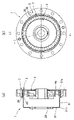
- FIG. 1A is a vertical sectional view showing an example of a cup-shaped wave gear device to which the present invention is applied
- FIG. 1B is an end view thereof.
- the strain wave gearing 1 includes an annular rigid internal gear 2, a cup-shaped flexible external gear 3 coaxially arranged inside the internal gear 2, and an elliptical contour fitted inside the flexible external gear 3. It has a wave generator 4.
- the internal gear 2 and the external gear 3 are spur gears of the same module (m). Further, the difference in the number of teeth of both gears is 2n (n is a positive integer), and the internal teeth 20 of the internal gear 2 are larger.
- the external teeth 30 of the external gear 3 are elliptically bent by a wave generator 4 having an elliptical contour, and mesh with the internal teeth 20 of the internal gear 2 at both ends in the direction of the elliptical major axis L1. .. When the wave generator 4 is rotated, the meshing position of both teeth 20 and 30 moves in the circumferential direction, and relative rotation corresponding to the difference in the number of teeth of both teeth 20 and 30 is generated between the gears 2 and 3.
- the external gear 3 has a flexible cylindrical body portion 31, a diaphragm 32 continuously extending radially along the rear end 31b at one end thereof, and a rigid annular boss 33 continuous with the diaphragm 32. And have.
- the outer teeth 30 are formed on the outer peripheral surface portion on the side of the opening end 31a, which is the other end (front end) of the cylindrical body portion 31.
- the wave generator 4 is fitted in the inner peripheral surface portion of the external tooth forming portion of the cylindrical body portion 31 of the external tooth gear 3. Due to the wave generator 4 having an elliptical contour, the cylindrical body portion 31 of the external gear 3 gradually increases the amount of bending outward or inward in the radial direction from the rear end 31b on the diaphragm side toward the opening end 31a. ing.
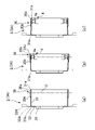
- FIG. 2 shows a state in which the cup-shaped external tooth gear 3 is bent in an elliptical shape
- FIG. 2 (a) is a cross-sectional view showing a state before deformation
- FIG. 2 (b) is an elliptical curve after deformation
- 2 (c) is a cross-sectional view of the minor axis position of the elliptical curve after deformation.
- the broken line in FIGS. 2 (a) to 2 (c) indicates a top hat-shaped external gear 3A.
- the diaphragm 32A extends radially outward from the rear end 31b of the cylindrical body portion 31, and an annular boss 33A is formed at the outer peripheral end thereof.
- the bending state of the external tooth forming portion of the external tooth gear 3A is the same as that of the cup-shaped external tooth gear 3.
- FIG. 2B in the cross section including the long axis L1 of the elliptical curve, the amount of outward deflection gradually increases in proportion to the distance from the rear end 31b to the opening end 31a
- FIG. 2C shows.
- the amount of inward deflection gradually increases in proportion to the distance from the rear end 31b to the opening end 31a.
- the amount of bending of the external tooth 30 formed on the outer peripheral surface portion on the opening end 31a side changes in the cross section perpendicular to each axis in the direction of the tooth muscle.
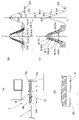
- FIG. 3 is a diagram showing three examples of the movement locus of the external tooth 30 of the external gear 3 with respect to the internal tooth 20 of the internal gear 2 in the strain wave gearing 1.
- the amount of deflection with respect to the rim neutral circle is 2 ⁇ mn with ⁇ as the deflection coefficient.
- the origin of the y-axis in FIG. 3 is the average position of the amplitude of the movement locus.
- the positive deviation movement locus Mo is a deflection coefficient ⁇ >. It is obtained in the case of the bending state of the positive deviation which is 1, and the negative deviation movement locus Mi is obtained in the case of the bending state of the negative deviation where the deflection coefficient ⁇ ⁇ 1.
- the cross section perpendicular to the axis at an arbitrary position in the tooth muscle direction for example, the position of the diameter line C passing through the center of the ball 4a of the wave bearing or the position of the outer tooth outer end 30a on the side of the opening end 31a (see FIG. 2) is used as a reference.
- both the tooth profile of the external tooth 30 and the tooth profile of the internal tooth 20 are aligned along the tooth muscle direction based on the amount of radial deflection of the external tooth 30 at each position of the external tooth 30 in the tooth muscle direction. Therefore, it is a three-dimensional tooth profile in which the tooth profile gradually changes.
- An example of the tooth profile of the internal teeth 20 and the external teeth 30 will be described below.
- FIG. 4A is an explanatory diagram showing contour shapes in the tooth muscle direction of the internal teeth 20 of the internal gear 2 and the external teeth 30 of the external gear 3.
- FIG. 4B is an explanatory diagram showing the tooth profile contour shape at the position of each cross section of the internal tooth 20 in the tooth muscle direction (cross section when cut in an orthogonal cross section orthogonal to the tooth muscle direction).
- FIG. 4C is an explanatory diagram showing the tooth profile contour shape at the position of each cross section of the external tooth 30 in the tooth muscle direction (cross section when cut in an orthogonal cross section orthogonal to the tooth muscle direction).
- FIG. 4D is an enlarged explanatory view showing a portion of the internal tooth 20 on the side of the internal end of the internal tooth.
- the tooth thickness direction is X
- the tooth length direction is Y
- the tooth muscle direction is Z
- the tooth profile contour shape of the internal tooth 20 is a three-dimensional tooth profile in which the tooth profile gradually changes along the tooth muscle.
- the tooth profile at the position of the other cross section in the tooth muscle direction of the internal tooth 20 is a reduction ratio set according to the amount of deflection at the position of the corresponding external tooth 30, and the basic internal tooth profile 20 (0) is proportionally reduced only in the lateral direction. It has a proportionally reduced tooth profile.
- the lateral direction of the tooth profile that is, the reduction ratio in the tooth thickness direction X is substantially proportional to the distance in the tooth muscle direction Z from the outer end 20a of the internal tooth to each cross-sectional position. And is decreasing.
- the internal tooth 20 has a constant tooth length in the direction of the tooth muscle. Further, the tooth thickness decreases and the pressure angle at the pitch point gradually increases according to the distance from the outer end 20a of the internal tooth in the direction of the tooth muscle.
- the tooth profile of the external tooth 30 is also a three-dimensional tooth profile in which the tooth profile gradually changes along the tooth muscle.
- the external tooth 30 has a tapered tooth profile having a constant tooth length, and the tooth tip circle gradually increases from the external tooth outer end 30a to the external tooth inner end 30b.
- the tooth tip circle increases according to the amount of bending at each position in the tooth muscle direction (increases according to the distance from the outer tooth outer end 30a).
- the tooth profile at the position of the other cross section in the tooth muscle direction Z of the external tooth 30 is a proportionally expanded tooth profile obtained by proportionally expanding the basic external tooth profile 30 (0) only in the lateral direction.
- the basic external tooth profile 30 (0) at the cross-sectional position (external tooth outer end 30a) where the Z value is “0” and the Z values “2.6” and “4.6” are shown.
- "7", “8.5” and “10” proportionally expanded tooth profiles 30 (2.6), 30 (4.6), 30 (7), 30 (8.5), 30 (10) is shown.
- the proportionally enlarged tooth profile 30 (10) shown by the imaginary line has the shape shown by the solid line 30 (10a).
- the lateral direction of the tooth profile that is, the enlargement magnification in the tooth thickness direction X is substantially proportional to the distance in the tooth muscle direction Z from the external tooth outer end 30a to each cross-sectional position. Is increasing. Therefore, the tooth thickness increases and the pressure angle at the pitch point increases according to the distance in the tooth muscle direction from the outer tooth outer end 30a.
- the proportionally enlarged tooth profile 30 (10) at the cross-sectional position of the outer tooth inner end 30b is proportional to the basic external tooth profile 30 (0) at the cross-sectional position of the external tooth outer end 30a at a magnification of "1.3" in the lateral direction. It is an enlarged shape.
- the basic internal tooth profile 20 (0) at the cross-sectional position of the external tooth outer end 20a (position of the reference cross section) and the basic external tooth profile 30 (0) at the cross-sectional position of the external tooth outer end 30a (position of the reference cross section). ) Can be installed by a known tooth profile setting method.
- the tooth profile contour (tooth surface shape) of the basic internal tooth profile 20 (0) of the internal tooth 20 includes a meshing tooth surface portion 201 that meshes with the external tooth 30 of the external tooth gear 3 on the mating side.
- One end of the tooth tip side tooth surface portion 202 defined by a convex curve and a straight line is smoothly connected to the tooth end side end of the meshing portion 201.
- the tooth tip side tooth surface portion 202 extends from the tooth tip side end of the meshing tooth surface portion 201 to the tooth tip top portion 203 of the internal tooth 20.
- one end of the tooth bottom side tooth surface portion 204 defined by the concave curve is smoothly connected to the end on the tooth root side of the meshing tooth surface portion 201.
- the tooth bottom side tooth surface portion 204 extends from the tooth root side end of the meshing tooth surface portion 201 to the tooth bottom deepest portion 205 (tooth groove center position) of the internal tooth 20.
- the basic external tooth profile 30 (0) of the external tooth 30 is provided with a meshing tooth surface portion 301 that meshes with the internal tooth 20 on the other side.
- One end of the tooth tip side tooth surface portion 302 defined by the convex curve is smoothly connected to the end of the tooth end side of the meshing tooth surface portion 301.
- the tooth tip side tooth surface portion 302 extends from the tooth tip side end to the tooth tip apex 303 of the external tooth 30.
- one end of the tooth bottom side tooth surface portion 304 defined by the concave curve and the straight line is smoothly connected to the tooth root side end of the meshing tooth surface portion 301.
- the tooth bottom side tooth surface portion 304 extends from the tooth root side end of the meshing tooth surface portion 301 to the tooth bottom deepest portion 305 (tooth groove center position) of the external tooth 30.
- the tooth profile that defines the meshing tooth surface portions 201 and 301 of the internal teeth 20 and the external teeth 30 is defined by a tooth profile curve such as an involute curve tooth profile that has been conventionally adopted. Further, the movement locus of the external tooth 30 with respect to the internal tooth 20 may be obtained, and the tooth profile of the meshing tooth surface portion of the internal tooth and the external tooth may be set by using a part of the curve representing the movement locus. For example, as described in Japanese Patent Application Laid-Open No. 63-11943 and Japanese Patent Application Laid-Open No. 64-7944, the tooth profile curve can be defined.
- a curved portion in a predetermined range is taken out from the limit point of the meshing on the movement locus of the external tooth 30 obtained when the meshing of the external tooth 30 with respect to the internal tooth 20 is approximated to be a rack meshing. Based on the similarity curve of this curved portion, the tooth profile curve of the meshing tooth surface portion of the internal tooth and the external tooth is set.
- the tooth tip side tooth surface portions 202 and 302 and the tooth bottom side tooth surface portions 204 and 304 of the basic internal tooth profile 20 (0) and the basic external tooth profile 30 (0) are portions that are not involved in meshing. Basically, it can be defined by any convex curve, concave curve, or straight line that does not interfere with the tooth on the other side.
- FIG. 5A is an explanatory diagram showing the meshing state of the internal tooth 20 and the external tooth 30 on the side of the internal tooth inner end 20b in which the tooth profile shape is set at each position in the tooth muscle direction as described above. be.
- the movement locus ( ⁇ ⁇ 1) of the internal tooth 20 has a shallow approach angle with respect to the external tooth 30. Therefore, in the meshing on the side of the inner end 20b of the internal tooth, the tooth surface portion 302 on the tip side of the external tooth 30 may interfere with the tooth surface portion 202 on the tooth tip side of the internal tooth 20.
- FIG. 5B is an explanatory diagram showing a tooth profile shape at each cross-sectional position of the external tooth 30 set so that the external tooth 30 does not interfere with the internal tooth 20 at each cross-sectional position in the tooth muscle direction.
- the curve defining the tooth surface portion on the tooth tip side is like a two-step bent curve. It becomes a complicated curve and is not easy to process.
- the gear cutting of the internal gear 2 whose tip circle changes in this way can be performed, for example, by using the blank material of the internal gear having the shape shown in FIG.
- the blank material 100 is a cylindrical member as a whole, and has an inner diameter from one end to the other along the axial direction (direction of the internal tooth muscle). It has a first cylindrical portion 101 whose dimensions correspond to the inner diameter of the first tooth tip circle, and a tapered inner peripheral surface whose inner diameter gradually increases from the inner diameter of the first tooth tip circle to the inner diameter of the second tooth tip circle.
- a second cylindrical portion 102 and a third cylindrical portion 103 whose inner diameter corresponds to the inner diameter of the second tooth tip circle are provided.
- 7 (a) to 7 (f) are explanatory views showing the meshing state of the external tooth 30 with respect to the internal tooth 20 at each cross-sectional position of the external tooth 30 in the tooth muscle direction.
- a curve representing the tooth profile of the internal tooth 20 having zero meshing backlash with the external tooth 30 Two curves are shown, one is a curve in which the tooth profile is slightly shifted in the radial direction away from the outer tooth.
- the strain wave gearing 1 As the tooth profile of the internal tooth 20 and the external tooth 30, a three-dimensional tooth profile in which the tooth profile (tooth thickness, pressure angle) gradually changes along the tooth muscle is adopted. ing.
- the direction of the tooth muscle in each three-dimensional tooth profile is The amount of change (change in tooth thickness, pressure angle, tooth length, tooth tip circle diameter, etc.) is small. Therefore, as compared with the case where only the external teeth have a three-dimensional tooth profile, the restrictions on the tooth cutting process are relaxed, and the tooth cutting process of the external teeth and the internal teeth capable of realizing the three-dimensional meshing becomes easy.
- the internal and external teeth set the basic internal and basic external tooth profiles that can mesh with each other in the reference cross section set at a predetermined position in the tooth muscle direction, and these are set in other positions in the tooth muscle direction.
- the tooth profile is proportionally reduced and expanded only in the lateral direction (tooth thickness direction) at a magnification according to the amount of bending of the external tooth at each position in the tooth muscle direction.
- the internal tooth cutting process can be performed by skiving process.
- the crossing angle of the tool tooth profile provided with the basic tooth profile with respect to the work may be gradually changed with the movement in the direction of the tooth muscle.
- the tooth cutting process of the external tooth can be performed by hob processing.
- a tool tooth profile whose thickness continuously changes in the direction of the tooth muscle is manufactured, and the hob is shifted according to the movement in the direction of the tooth muscle at the time of gear cutting.
- by gradually changing the distance between the work and the hob as it moves in the direction of the tooth muscle it is possible to realize a tapered tooth profile in which the tip circle gradually increases along the direction of the tooth muscle. Therefore, it becomes easier to process the three-dimensional tooth profile of the external tooth and the internal tooth as compared with the three-dimensional tooth profile conventionally used for the external tooth.
- the majority portion of the internal tooth from the outer end of the internal tooth to the inner end of the internal tooth in the direction of the tooth muscle is the first internal tooth portion having the same first tooth tip circle as the tooth tip circle of the basic internal tooth profile. be.
- the remaining portion of the internal tooth including the internal end of the internal tooth is modified in the tip portion of the proportionally reduced tooth profile so as to be larger than the tip circle of the basic internal tooth profile.
- the approach angle to the internal tooth becomes shallow, and the tip portion of the external tooth interferes with the tip portion of the internal tooth.
- the tooth tip circle of the internal tooth on the side of the internal end of the internal tooth is made larger than the other part in the direction of the tooth muscle, the tooth tip of the internal tooth is separated so as not to interfere with the tooth tip of the external tooth. be able to. As a result, interference between both teeth can be reliably avoided.
Landscapes
- Engineering & Computer Science (AREA)
- General Engineering & Computer Science (AREA)
- Mechanical Engineering (AREA)
- Gears, Cams (AREA)
- Retarders (AREA)
Abstract
A three-dimensional tooth profile of an internal gear tooth (20) of a wave gear device (1) is a basic internal gear tooth profile (20(0)) at an internal gear tooth outer end (20a), and is a reduced tooth profile, which is obtained by proportionally reducing the basic internal gear tooth profile (20(0)) only in the transverse direction, at the other positions in the tooth trace direction. A three-dimensional tooth profile of an outer gear tooth (3) is a basic outer gear tooth profile (30(0)) at an outer gear tooth outer end (30a), and is an enlarged tooth profile, which is obtained by proportionally enlarging the basic outer gear tooth profile (30(0)) only in the transverse direction, at the other positions in the tooth trace direction. The addendum of a part of the internal gear tooth (20) on an internal gear tooth inner end (20b) side is larger than that of the other parts, and inhibits interference with the outer gear tooth (30). The present invention can achieve the three-dimensional tooth profiles of the outer gear tooth (30) and the internal gear tooth (20) which three-dimensionally engage the outer gear teeth (30) and the internal gear teeth (20) with each other, which inhibit both teeth from interfering with each other on the internal gear tooth inner end (20b) side, and which facilitate gear cutting processing.
Description
本発明は、カップ型あるいはシルクハット型の波動歯車装置に関する。さらに詳しくは、内歯歯車と外歯歯車とが歯筋方向の各位置においてかみ合う3次元かみ合い状態を形成可能な三次元歯形を有する波動歯車装置に関する。
The present invention relates to a cup type or top hat type wave gear device. More specifically, the present invention relates to a wave gear device having a three-dimensional tooth profile capable of forming a three-dimensional meshing state in which the internal gear and the external gear mesh at each position in the tooth muscle direction.
カップ型あるいはシルクハット型の波動歯車装置は、剛性の内歯歯車と、この内側に同軸状に配置されたカップ形状あるいはシルクハット形状の可撓性の外歯歯車と、この内側に嵌めた波動発生器とを有している。外歯歯車は、可撓性の円筒状胴部と、この円筒状胴部の後端から半径方向に延びているダイヤフラムと、円筒状胴部の開口端の側の外周面部分に形成した外歯とを備えている。外歯歯車は波動発生器によって楕円状に撓められ、楕円の長軸方向の両端部において内歯歯車に噛み合っている。
Cup-type or top-hat-type wave gearing devices include rigid internal gears, cup-shaped or top-hat-shaped flexible external gears coaxially arranged inside the gears, and waves fitted inside the gears. Has a generator. The external gears are formed on a flexible cylindrical body, a diaphragm extending radially from the rear end of the cylindrical body, and an outer peripheral surface portion on the open end side of the cylindrical body. It has teeth. The external gear is elliptical flexed by a wave generator and meshes with the internal gear at both ends of the ellipse in the major axis direction.
波動歯車装置の基本歯形として、歯切り加工が容易な基準ラック歯形(インボリュート曲線歯形)が広く採用されている。インボリュート曲線歯形の利用は、特許文献1(特公昭45-41171号公報)において提案されている。
As the basic tooth profile of the strain wave gearing, the standard rack tooth profile (involute curved tooth profile) that is easy to cut is widely adopted. The use of an involute curved tooth profile is proposed in Patent Document 1 (Japanese Patent Laid-Open No. 45-41171).
一般的に用いられている波動歯車装置は、剛性の内歯歯車と、可撓性の外歯歯車と、外歯歯車を楕円形状に撓めて内歯歯車にかみ合わせる波動発生器とを備えている。外歯歯車の各歯は、波動発生器によって繰り返し半径方向に一定の振幅で撓められて、内歯歯車に対するかみ合い状態、かみ合い離脱状態が繰り返される。内歯歯車に対する外歯歯車のかみ合いの運動軌跡は、ラック近似で示すことができる。例えば、特許文献2(国際公開第2016/006102号)の図7には、外歯歯車が内歯歯車に対して、かみ合い離脱状態から最深かみ合い状態に至るまでの移動状態(最深かみ合い状態からかみ合い離脱状態に至るまでの移動状態)が示されている。
A commonly used strain wave gearing includes a rigid internal gear, a flexible external gear, and a wave generator that bends the external gear into an elliptical shape and engages the internal gear. ing. Each tooth of the external gear is repeatedly bent in the radial direction by a wave generator with a constant amplitude, and the meshing state and the meshing disengagement state with respect to the internal gear are repeated. The motion trajectory of the meshing of the external gear with respect to the internal gear can be shown by a rack approximation. For example, in FIG. 7 of Patent Document 2 (International Publication No. 2016/006102), the external gear is in a moving state (from the deepest meshing state to the deepest meshing state) with respect to the internal gear from the disengaged state to the deepest meshing state. The state of movement up to the state of withdrawal) is shown.
楕円状に撓められた外歯歯車の外歯は、歯筋方向の各位置において撓み状態が異なるので、内歯歯車の内歯に対するかみ合い状態も異なる。外歯における歯筋方向の一か所の軸直角断面上において、内歯に対して連続したかみ合い状態を形成可能な外歯歯形を設定しても、歯筋方向の他の位置では適切なかみ合い状態が形成されない。
Since the external teeth of the external gear that are bent in an elliptical shape have different bending states at each position in the direction of the tooth muscle, the meshing state of the internal gear with respect to the internal teeth also differs. Even if an external tooth profile that can form a continuous meshing state with respect to the internal tooth is set on a cross section perpendicular to the axis of one position in the direction of the tooth muscle in the external tooth, proper meshing is performed at another position in the direction of the tooth muscle. No state is formed.
特許文献3(特開2017-44287号公報)では、内歯歯車の歯形を、歯筋方向の各位置において同一の歯形とし、外歯歯形を直線歯形とすると共に、その両側の歯面を、歯筋方向に沿って、ダイヤフラム側の端から外歯歯車の開口端の側の端に向かって歯厚が漸増するように傾斜させた傾斜面にしている。これにより、外歯と内歯のかみ合い動作において、外歯のダイヤフラム側の歯先が、内歯の歯先に干渉することを防止している。
In Patent Document 3 (Japanese Unexamined Patent Publication No. 2017-445287), the tooth profile of the internal gear is the same tooth profile at each position in the tooth muscle direction, the external tooth profile is a straight tooth profile, and the tooth surfaces on both sides thereof are defined. The inclined surface is inclined so that the tooth thickness gradually increases from the end on the diaphragm side toward the end on the open end side of the external gear along the tooth muscle direction. This prevents the tooth tip on the diaphragm side of the external tooth from interfering with the tooth tip of the internal tooth in the meshing operation between the external tooth and the internal tooth.
特許文献4(国際公開第2013/046274号)では、カップ型あるいはシルクハット型の波動歯車装置において、剛性の内歯歯車の歯に対する可撓性の外歯歯車の歯の移動軌跡に基づき、内歯および外歯の基本歯形を設定している。内歯歯車の歯形を歯筋方向の各位置において同一の内歯基本歯形を採用している。また、外歯の歯形として、外歯基本歯形の歯筋方向の両側の部分に転位を施すことにより、歯筋方向において、開口端側からダイヤフラム側に向けて、歯先円直径が漸減しているテーパー型の歯形を採用している。歯筋に沿って歯形が変化している三次元歯形を採用することで、歯筋方向における一つの軸直角断面上でかみ合いが形成される二次元かみ合いの状態だけでなく、歯筋方向に沿った広い範囲において、内歯に外歯がかみ合う三次元かみ合いの状態を実現している。
In Patent Document 4 (International Publication No. 2013/046274), in a cup-type or silk hat-type wave gear device, an internal gear is based on the movement locus of a flexible external gear tooth with respect to a rigid internal gear tooth. The basic tooth profile of the teeth and external teeth is set. The tooth profile of the internal gear has the same basic internal tooth profile at each position in the direction of the tooth muscle. In addition, as the tooth profile of the external tooth, the diameter of the tip circle gradually decreases from the opening end side to the diaphragm side in the tooth muscle direction by dislocating both sides of the external tooth basic tooth profile in the tooth muscle direction. Adopts a tapered tooth profile. By adopting a three-dimensional tooth profile in which the tooth profile changes along the tooth muscle, not only the two-dimensional meshing state in which the meshing is formed on one axis perpendicular cross section in the tooth muscle direction, but also along the tooth muscle direction. In a wide range, a three-dimensional meshing state in which the external teeth engage with the internal teeth is realized.
特許文献5(国際公開第2019/077719号)においては、カップ型あるいはシルクハット型の波動歯車装置において、剛性の内歯歯車の内歯の歯形を、その歯筋方向の各位置において同一としている。また、可撓性の外歯歯車の外歯の歯形を次のように設定している。外歯の歯先歯厚は、歯筋方向に沿って、外歯歯車の開口端の側の外歯外端から、外歯歯車のダイヤフラムの側の外歯内端に向けて漸減している。さらに、外歯のピッチ点における圧力角は、歯筋方向に沿って、外歯外端から外歯内端に向けて漸増している。外歯の歯形を、歯筋方向に沿って変化している三次元歯形とすることで、歯筋方向における一つの軸直角断面上でかみ合いが形成される二次元かみ合いの状態だけでなく、歯筋方向に沿った広い範囲において、内歯に対して外歯がかみ合う三次元かみ合いの状態を形成している。
In Patent Document 5 (International Publication No. 2019/0777719), in a cup-type or top-hat type wave gear device, the tooth profile of the internal teeth of a rigid internal gear is the same at each position in the tooth muscle direction. .. In addition, the tooth profile of the external teeth of the flexible external gear is set as follows. The tooth tip thickness of the external tooth gradually decreases from the external tooth outer end on the side of the open end of the external tooth gear toward the external tooth inner end on the diaphragm side of the external tooth gear along the tooth muscle direction. .. Further, the pressure angle at the pitch point of the external tooth gradually increases from the outer end of the external tooth to the inner end of the external tooth along the direction of the tooth muscle. By making the tooth profile of the external tooth a three-dimensional tooth profile that changes along the tooth muscle direction, not only the state of the two-dimensional meshing in which the meshing is formed on one axis perpendicular cross section in the tooth muscle direction, but also the tooth. It forms a three-dimensional meshing state in which the external teeth engage with the internal teeth in a wide range along the muscle direction.
一般に、カップ型あるいはシルクハット型の波動歯車装置においては、三次元かみ合い状態を形成するために、内歯歯車の歯形をその歯筋に沿って同一の歯形とし、外歯歯車の外歯を歯筋に沿って歯形形状を変化させた三次元歯形としている。
Generally, in a cup-type or silk hat-type wave gear device, in order to form a three-dimensional meshing state, the tooth profile of the internal gear has the same tooth profile along the tooth muscle, and the external teeth of the external gear have teeth. It is a three-dimensional tooth profile in which the tooth profile shape is changed along the muscle.
外歯歯車を三次元かみ合い歯形として設計する場合には次のような課題がある。歯切り盤による歯切り加工上の制約により、歯厚、圧力角、歯丈等が歯筋方向に沿って設計通りに変化する歯形を切削することが困難な場合がある。
When designing an external gear as a three-dimensional meshing tooth profile, there are the following problems. Due to restrictions on tooth cutting by the tooth cutting machine, it may be difficult to cut a tooth profile in which the tooth thickness, pressure angle, tooth length, etc. change as designed along the tooth muscle direction.
本発明の目的は、この点に鑑みて、干渉を起こすことなく歯筋方向の全体に亘る三次元かみ合いを容易に実現でき、かつ、歯切り加工が容易な三次元歯形を、外歯および内歯の歯形形状に採用した波動歯車装置を提供することにある。
In view of this point, an object of the present invention is to provide a three-dimensional tooth profile that can easily realize three-dimensional meshing over the entire tooth muscle direction without causing interference and that is easy to perform gear cutting, for external teeth and internal teeth. It is an object of the present invention to provide a strain wave gearing adopted for a tooth profile of a tooth.
上記の課題を解決するために、本発明は、剛性の内歯歯車、カップ形状あるいはシルクハット形状をした可撓性の外歯歯車および波動発生器を備えたカップ型あるいはシルクハット型の波動歯車装置において、外歯歯車の外歯の歯筋方向の所定の位置において歯筋方向に直交する直交面で切断した場合の断面を基準断面とし、内歯歯車の内歯の歯筋方向における外歯外端に対応する側の端を内歯外端、他方の端を内歯内端とすると、外歯および内歯は、次のように、三次元歯形に設定されている。基準断面上における外歯の歯形輪郭形状は基本外歯歯形としてあり、基準断面に対応する内歯の断面位置における内歯の歯形輪郭形状は、基本外歯歯形にかみ合い可能に設定された基本内歯歯形としてある。また、内歯の歯筋方向の各位置における内歯歯形輪郭は、前記各位置における前記外歯の撓み量に応じた倍率で、基本内歯歯形を歯厚方向にのみ比例縮小して得られる比例縮小歯形である。外歯は、歯筋方向に沿ってみた場合に、外歯外端から外歯内端に向かって歯底円が漸増している歯丈が一定のテーパー歯形であり、外歯の歯筋方向の各位置における歯形輪郭は、前記各位置における前記外歯の撓み量に応じた倍率で、基本外歯歯形を歯厚方向にのみ比例拡大して得られる比例拡大歯形である。これに加えて、本発明の波動歯車装置においては、内歯における内歯外端から内歯内端に向けて歯筋方向の過半部分は、基本内歯歯形の歯先円と同一の第1歯先円を備えた第1内歯部分である。これに対して、内歯における内歯内端を含む残りの部分は、基本内歯歯形の歯先円よりも大きくなるように、比例縮小歯形の歯先部分に歯形修正が施されている。
In order to solve the above problems, the present invention presents a cup-shaped or silk-hat-shaped wave gear equipped with a rigid internal tooth gear, a cup-shaped or silk-hat-shaped flexible external tooth gear, and a wave generator. In the device, the cross section when the external tooth gear is cut at a predetermined position in the tooth muscle direction of the external tooth gear on an orthogonal plane orthogonal to the tooth muscle direction is used as a reference cross section, and the external tooth in the tooth muscle direction of the internal tooth of the internal tooth gear is used as a reference cross section. Assuming that the end corresponding to the outer end is the outer end of the inner tooth and the other end is the inner end of the inner tooth, the outer tooth and the inner tooth are set to a three-dimensional tooth profile as follows. The tooth profile contour shape of the external tooth on the reference cross section is the basic external tooth profile, and the tooth profile contour shape of the internal tooth at the cross-sectional position of the internal tooth corresponding to the reference cross section is set to be meshable with the basic external tooth profile. It is a tooth profile. Further, the contour of the internal tooth profile at each position in the tooth muscle direction of the internal tooth is obtained by proportionally reducing the basic internal tooth profile only in the tooth thickness direction at a magnification corresponding to the amount of bending of the external tooth at each position. It is a proportionally reduced tooth profile. The external tooth has a tapered tooth profile in which the root circle gradually increases from the outer end of the external tooth to the inner end of the external tooth when viewed along the direction of the tooth muscle, and the tooth length is constant, and the tooth direction of the external tooth. The tooth profile contour at each position is a proportionally expanded tooth profile obtained by proportionally expanding the basic external tooth profile only in the tooth thickness direction at a magnification corresponding to the amount of bending of the external tooth at each position. In addition to this, in the wave gear device of the present invention, the majority portion of the internal tooth in the direction of the tooth muscle from the outer end of the internal tooth to the inner end of the internal tooth is the same as the tip circle of the basic internal tooth profile. It is the first internal tooth portion having a tooth tip circle. On the other hand, the remaining portion of the internal tooth including the internal end of the internal tooth is modified in the tip portion of the proportionally reduced tooth profile so as to be larger than the tip circle of the basic internal tooth profile.
このように、本発明の波動歯車装置の内歯の三次元歯形は、内歯外端では基本内歯歯形であり、歯筋方向の他の位置では、基本内歯歯形を横方向のみに比例縮小した縮小歯形である。外歯の三次元歯形は、外歯外端では基本外歯歯形であり、歯筋方向の他の位置では、基本外歯歯形を横方向のみに比例拡大した拡大歯形である。内歯の内歯内端の側の部分の歯先円を他の部分に比べて大きく、外歯と干渉しない。外歯と内歯が三次元かみ合いを行い、内歯内端の側において両歯が干渉せず、かつ歯切り加工が容易な外歯、内歯の三次元歯形を実現できる。
As described above, the three-dimensional tooth profile of the internal tooth of the strain wave gearing device of the present invention is the basic internal tooth profile at the outer end of the internal tooth, and is proportional to the basic internal tooth profile only in the lateral direction at other positions in the tooth muscle direction. It is a reduced tooth profile. The three-dimensional tooth profile of the external tooth is a basic external tooth profile at the outer end of the external tooth, and is an enlarged tooth profile in which the basic external tooth profile is proportionally expanded only in the lateral direction at other positions in the tooth muscle direction. The tip circle of the part of the internal tooth on the side of the inner end of the internal tooth is larger than that of other parts and does not interfere with the external tooth. It is possible to realize a three-dimensional tooth profile of an external tooth and an internal tooth in which the external tooth and the internal tooth engage in three-dimensional meshing, the two teeth do not interfere with each other on the inner end side of the internal tooth, and the tooth cutting process is easy.
以下に、図面を参照して、本発明を適用した波動歯車装置を説明する。図1(a)は本発明を適用したカップ型の波動歯車装置の一例を示す縦断面図であり、図1(b)はその端面図である。
The wave gear device to which the present invention is applied will be described below with reference to the drawings. FIG. 1A is a vertical sectional view showing an example of a cup-shaped wave gear device to which the present invention is applied, and FIG. 1B is an end view thereof.
波動歯車装置1は、円環状の剛性の内歯歯車2と、その内側に同軸状に配置されたカップ形状をした可撓性の外歯歯車3と、この内側にはめ込まれた楕円状輪郭の波動発生器4とを有している。内歯歯車2と外歯歯車3は同一モジュール(m)の平歯車である。また、両歯車の歯数差は2n(nは正の整数)であり、内歯歯車2の内歯20の方が多い。外歯歯車3の外歯30は、楕円状輪郭の波動発生器4によって楕円状に撓められ、楕円状の長軸L1の方向の両端部分において内歯歯車2の内歯20にかみ合っている。波動発生器4を回転すると、両歯20、30のかみ合い位置が周方向に移動し、両歯20、30の歯数差に応じた相対回転が両歯車2、3の間に発生する。
The strain wave gearing 1 includes an annular rigid internal gear 2, a cup-shaped flexible external gear 3 coaxially arranged inside the internal gear 2, and an elliptical contour fitted inside the flexible external gear 3. It has a wave generator 4. The internal gear 2 and the external gear 3 are spur gears of the same module (m). Further, the difference in the number of teeth of both gears is 2n (n is a positive integer), and the internal teeth 20 of the internal gear 2 are larger. The external teeth 30 of the external gear 3 are elliptically bent by a wave generator 4 having an elliptical contour, and mesh with the internal teeth 20 of the internal gear 2 at both ends in the direction of the elliptical major axis L1. .. When the wave generator 4 is rotated, the meshing position of both teeth 20 and 30 moves in the circumferential direction, and relative rotation corresponding to the difference in the number of teeth of both teeth 20 and 30 is generated between the gears 2 and 3.
外歯歯車3は、可撓性の円筒状胴部31と、その一端である後端31bに連続して半径方向に広がるダイヤフラム32と、ダイヤフラム32に連続している剛性の円環状のボス33とを備えている。外歯30は、円筒状胴部31の他端(前端)である開口端31aの側の外周面部分に形成されている。波動発生器4は、外歯歯車3の円筒状胴部31の外歯形成部分の内周面部分に嵌め込まれている。楕円状輪郭の波動発生器4によって、外歯歯車3の円筒状胴部31は、そのダイヤフラム側の後端31bから開口端31aに向けて、半径方向の外側あるいは内側への撓み量が漸増している。
The external gear 3 has a flexible cylindrical body portion 31, a diaphragm 32 continuously extending radially along the rear end 31b at one end thereof, and a rigid annular boss 33 continuous with the diaphragm 32. And have. The outer teeth 30 are formed on the outer peripheral surface portion on the side of the opening end 31a, which is the other end (front end) of the cylindrical body portion 31. The wave generator 4 is fitted in the inner peripheral surface portion of the external tooth forming portion of the cylindrical body portion 31 of the external tooth gear 3. Due to the wave generator 4 having an elliptical contour, the cylindrical body portion 31 of the external gear 3 gradually increases the amount of bending outward or inward in the radial direction from the rear end 31b on the diaphragm side toward the opening end 31a. ing.
図2はカップ形状の外歯歯車3を楕円状に撓ませた状態を示し、図2(a)は変形前の状態を示す断面図であり、図2(b)は変形後における楕円状曲線の長軸位置の断面図であり、図2(c)は変形後における楕円状曲線の短軸位置の断面図である。なお、図2(a)~(c)における破線は、シルクハット形状の外歯歯車3Aを示す。シルクハット形状の外歯歯車3Aは、円筒状胴部31の後端31bから半径方向の外方にダイヤフラム32Aが延び、その外周端に円環状のボス33Aが形成されている。外歯歯車3Aの外歯形成部分の撓み状態は、カップ形状の外歯歯車3と同様である。
FIG. 2 shows a state in which the cup-shaped external tooth gear 3 is bent in an elliptical shape, FIG. 2 (a) is a cross-sectional view showing a state before deformation, and FIG. 2 (b) is an elliptical curve after deformation. 2 (c) is a cross-sectional view of the minor axis position of the elliptical curve after deformation. The broken line in FIGS. 2 (a) to 2 (c) indicates a top hat-shaped external gear 3A. In the top hat-shaped external gear 3A, the diaphragm 32A extends radially outward from the rear end 31b of the cylindrical body portion 31, and an annular boss 33A is formed at the outer peripheral end thereof. The bending state of the external tooth forming portion of the external tooth gear 3A is the same as that of the cup-shaped external tooth gear 3.
図2(b)に示すように、楕円状曲線の長軸L1を含む断面では外側への撓み量が後端31bから開口端31aへの距離に比例して漸増し、図2(c)に示すように、楕円状曲線の短軸L2を含む断面では内側への撓み量が後端31bから開口端31aへの距離に比例して漸増している。開口端31a側の外周面部分に形成されている外歯30は、その歯筋方向における各軸直角断面において撓み量が変化している。すなわち、外歯30の歯筋方向におけるダイヤフラム側の外歯内端30bから開口端31a側の外歯外端30aに向けて、後端31bからの距離に比例して、半径方向への撓み量が漸増している。
As shown in FIG. 2B, in the cross section including the long axis L1 of the elliptical curve, the amount of outward deflection gradually increases in proportion to the distance from the rear end 31b to the opening end 31a, and FIG. 2C shows. As shown, in the cross section including the short axis L2 of the elliptical curve, the amount of inward deflection gradually increases in proportion to the distance from the rear end 31b to the opening end 31a. The amount of bending of the external tooth 30 formed on the outer peripheral surface portion on the opening end 31a side changes in the cross section perpendicular to each axis in the direction of the tooth muscle. That is, the amount of deflection in the radial direction from the outer tooth inner end 30b on the diaphragm side in the tooth muscle direction of the outer tooth 30 toward the outer tooth outer end 30a on the opening end 31a side in proportion to the distance from the rear end 31b. Is gradually increasing.
図3は波動歯車装置1における内歯歯車2の内歯20に対する外歯歯車3の外歯30の移動軌跡の三例を示す図である。外歯歯車3の外歯30の歯筋方向における任意の位置の軸直角断面において、外歯30の楕円状リム中立線における長軸L1の位置では、外歯30が楕円状に撓む前のリム中立円に対する撓み量は、κを撓み係数として2κmnである。
FIG. 3 is a diagram showing three examples of the movement locus of the external tooth 30 of the external gear 3 with respect to the internal tooth 20 of the internal gear 2 in the strain wave gearing 1. In the cross section perpendicular to the axis of the external tooth 30 of the external tooth gear 3 at an arbitrary position in the tooth muscle direction, at the position of the long axis L1 on the neutral line of the elliptical rim of the external tooth 30, before the external tooth 30 bends in an elliptical shape. The amount of deflection with respect to the rim neutral circle is 2κmn with κ as the deflection coefficient.
図3のy軸の原点は移動軌跡の振幅の平均位置としてある。移動軌跡のうち無偏位移動軌跡M1は、撓み係数κ=1である偏位無しの標準の撓み状態の場合に得られるものであり、正偏位移動軌跡Moは、撓み係数κ>1である正偏位の撓み状態の場合に得られるものであり、負偏位移動軌跡Miは、撓み係数κ<1である負偏位の撓み状態の場合に得られるものである。歯筋方向の任意の位置、例えば、ウエーブベアリングのボール4aの中心を通る直径線Cの位置または開口端31aの側の外歯外端30aの位置(図2参照)における軸直角断面が、基準断面として設定される。基準断面において、撓み係数κ=1の無偏位移動軌跡が得られるように、撓み量が設定される。
The origin of the y-axis in FIG. 3 is the average position of the amplitude of the movement locus. Of the movement loci, the non-deviation movement locus M 1 is obtained in the case of a standard deflection state without deviation with a deflection coefficient κ = 1, and the positive deviation movement locus Mo is a deflection coefficient κ>. It is obtained in the case of the bending state of the positive deviation which is 1, and the negative deviation movement locus Mi is obtained in the case of the bending state of the negative deviation where the deflection coefficient κ <1. The cross section perpendicular to the axis at an arbitrary position in the tooth muscle direction, for example, the position of the diameter line C passing through the center of the ball 4a of the wave bearing or the position of the outer tooth outer end 30a on the side of the opening end 31a (see FIG. 2) is used as a reference. Set as a cross section. In the reference cross section, the amount of deflection is set so that a non-deviation movement locus with a deflection coefficient κ = 1 can be obtained.
(三次元歯形の例)
本例では、外歯30の歯筋方向の各位置における外歯30の半径方向への撓み量に基づき、外歯30の歯形および内歯20の歯形の双方を、それらの歯筋方向に沿って、歯形形状が徐々に変化する三次元歯形としてある。以下に、内歯20および外歯30の歯形形状の例を説明する。 (Example of three-dimensional tooth profile)
In this example, both the tooth profile of theexternal tooth 30 and the tooth profile of the internal tooth 20 are aligned along the tooth muscle direction based on the amount of radial deflection of the external tooth 30 at each position of the external tooth 30 in the tooth muscle direction. Therefore, it is a three-dimensional tooth profile in which the tooth profile gradually changes. An example of the tooth profile of the internal teeth 20 and the external teeth 30 will be described below.
本例では、外歯30の歯筋方向の各位置における外歯30の半径方向への撓み量に基づき、外歯30の歯形および内歯20の歯形の双方を、それらの歯筋方向に沿って、歯形形状が徐々に変化する三次元歯形としてある。以下に、内歯20および外歯30の歯形形状の例を説明する。 (Example of three-dimensional tooth profile)
In this example, both the tooth profile of the
図4(a)は、内歯歯車2の内歯20および外歯歯車3の外歯30のそれぞれの歯筋方向の輪郭形状を示す説明図である。図4(b)は、内歯20の歯筋方向の各断面(歯筋方向に直交する直交断面で切断した場合の断面)の位置での歯形輪郭形状を示す説明図である。図4(c)は、外歯30の歯筋方向の各断面(歯筋方向に直交する直交断面で切断した場合の断面)の位置での歯形輪郭形状を示す説明図である。図4(d)は内歯20の内歯内端の側の部分を拡大して示す説明図である。これらの図において、歯厚方向をX、歯丈方向をY、歯筋方向をZとし、内歯外端20aをZ=0の断面位置、内歯内端20bをZ=10の断面位置とする。
FIG. 4A is an explanatory diagram showing contour shapes in the tooth muscle direction of the internal teeth 20 of the internal gear 2 and the external teeth 30 of the external gear 3. FIG. 4B is an explanatory diagram showing the tooth profile contour shape at the position of each cross section of the internal tooth 20 in the tooth muscle direction (cross section when cut in an orthogonal cross section orthogonal to the tooth muscle direction). FIG. 4C is an explanatory diagram showing the tooth profile contour shape at the position of each cross section of the external tooth 30 in the tooth muscle direction (cross section when cut in an orthogonal cross section orthogonal to the tooth muscle direction). FIG. 4D is an enlarged explanatory view showing a portion of the internal tooth 20 on the side of the internal end of the internal tooth. In these figures, the tooth thickness direction is X, the tooth length direction is Y, the tooth muscle direction is Z, the inner tooth outer end 20a is the cross-sectional position of Z = 0, and the inner tooth inner end 20b is the cross-sectional position of Z = 10. do.
内歯20の歯形輪郭形状は、歯筋に沿って歯形が徐々に変化している三次元歯形である。例えば、その歯筋方向Zにおける内歯外端20aの断面位置(Z=0)において、内歯20の歯形輪郭形状は、基本内歯歯形20(0)に設定されている。内歯20の歯筋方向における他の断面の位置の歯形は、対応する外歯30の位置における撓み量に応じて設定した縮小倍率で、基本内歯歯形20(0)を横方向のみ比例縮小した比例縮小歯形となっている。
The tooth profile contour shape of the internal tooth 20 is a three-dimensional tooth profile in which the tooth profile gradually changes along the tooth muscle. For example, the tooth profile contour shape of the internal tooth 20 is set to the basic internal tooth profile 20 (0) at the cross-sectional position (Z = 0) of the internal tooth outer end 20a in the tooth muscle direction Z. The tooth profile at the position of the other cross section in the tooth muscle direction of the internal tooth 20 is a reduction ratio set according to the amount of deflection at the position of the corresponding external tooth 30, and the basic internal tooth profile 20 (0) is proportionally reduced only in the lateral direction. It has a proportionally reduced tooth profile.
図4(b)には、Zの値が「0」の断面位置(内歯外端20a)の基本内歯歯形20(0)と、Zの値が「2.6」、「4.6」、「7」、「8.5」および「10」(内歯内端20b)の5つの断面位置における比例縮小歯形20(2.6)、20(4.6)、20(7)、20(8.5)、20(10)を、Z=0の断面上に重ねた状態で示してある。例えば、Z=0の位置が撓み係数κ=1の位置である。
In FIG. 4B, the basic internal tooth profile 20 (0) at the cross-sectional position (internal tooth outer end 20a) where the Z value is “0” and the Z values “2.6” and “4.6” are shown. , "7", "8.5" and "10" (inner end 20b of the internal tooth), proportionally reduced tooth profiles 20 (2.6), 20 (4.6), 20 (7), 20 (8.5) and 20 (10) are shown in a state of being overlapped on a cross section of Z = 0. For example, the position where Z = 0 is the position where the deflection coefficient κ = 1.
内歯20の歯筋方向Zの各断面位置における比例縮小歯形の横方向、すなわち歯厚方向Xの縮小倍率は、内歯外端20aから各断面位置までの歯筋方向Zの距離にほぼ比例して減少している。内歯20は歯筋方向において歯丈が一定である。また、内歯外端20aからの歯筋方向の距離に応じて、歯厚が減少し、ピッチ点における圧力角が漸増している。例えば、内歯内端20bの断面位置(Z=10)における比例縮小歯形20(10)は、内歯外端20aの断面位置の基本内歯歯形20(0)の倍率を「1」とすると、横方向に倍率1.3で比例縮小した形状である。
Proportional reduction at each cross-sectional position of the internal tooth 20 in the tooth muscle direction Z The lateral direction of the tooth profile, that is, the reduction ratio in the tooth thickness direction X is substantially proportional to the distance in the tooth muscle direction Z from the outer end 20a of the internal tooth to each cross-sectional position. And is decreasing. The internal tooth 20 has a constant tooth length in the direction of the tooth muscle. Further, the tooth thickness decreases and the pressure angle at the pitch point gradually increases according to the distance from the outer end 20a of the internal tooth in the direction of the tooth muscle. For example, the proportionally reduced tooth profile 20 (10) at the cross-sectional position (Z = 10) of the internal tooth inner end 20b is assumed to have a magnification of the basic internal tooth profile 20 (0) at the cross-sectional position of the internal tooth outer end 20a as "1". , It is a shape that is proportionally reduced in the horizontal direction at a magnification of 1.3.
外歯30の歯形も、歯筋に沿って歯形が徐々に変化している三次元歯形である。本例では、その歯筋方向Zにおける外歯外端30aの断面位置(Z=0)において、外歯30の歯形輪郭形状は、内歯20の内歯外端20aの基本内歯歯形20(0)にかみ合い可能な基本外歯歯形30(0)に設定されている。例えば、外歯30は歯丈が一定のテーパー歯形であり、外歯外端30aから外歯内端30bに向けて、歯先円が漸増している。歯先円は、歯筋方向の各位置における撓み量に応じて増加している(外歯外端30aからの距離に応じて増加している)。
The tooth profile of the external tooth 30 is also a three-dimensional tooth profile in which the tooth profile gradually changes along the tooth muscle. In this example, at the cross-sectional position (Z = 0) of the external tooth outer end 30a in the tooth muscle direction Z, the tooth profile contour shape of the external tooth 30 is the basic internal tooth profile 20 of the internal tooth outer end 20a of the internal tooth 20 (Z = 0). It is set to a basic external tooth profile 30 (0) that can engage with 0). For example, the external tooth 30 has a tapered tooth profile having a constant tooth length, and the tooth tip circle gradually increases from the external tooth outer end 30a to the external tooth inner end 30b. The tooth tip circle increases according to the amount of bending at each position in the tooth muscle direction (increases according to the distance from the outer tooth outer end 30a).
外歯外端30aはZ=0の断面位置、外歯内端30bはZ=10よりも僅かに内側の断面位置である。外歯30の歯筋方向Zにおける他の断面の位置の歯形は、基本外歯歯形30(0)を横方向のみ比例拡大した比例拡大歯形となっている。図4(c)には、Zの値が「0」の断面位置(外歯外端30a)の基本外歯歯形30(0)と、Zの値が「2.6」、「4.6」、「7」、「8.5」および「10」の5つの断面位置における比例拡大歯形30(2.6)、30(4.6)、30(7)、30(8.5)、30(10)を示してある。なお、外歯30におけるZ=10の断面位置は、外歯内端30bから外れた位置(有効歯幅から外れた位置)であり、歯丈が低くなっている。想像線で示す比例拡大歯形30(10)は、実線30(10a)で示す形状になる。
The outer tooth outer end 30a is the cross-sectional position of Z = 0, and the outer tooth inner end 30b is the cross-sectional position slightly inside of Z = 10. The tooth profile at the position of the other cross section in the tooth muscle direction Z of the external tooth 30 is a proportionally expanded tooth profile obtained by proportionally expanding the basic external tooth profile 30 (0) only in the lateral direction. In FIG. 4C, the basic external tooth profile 30 (0) at the cross-sectional position (external tooth outer end 30a) where the Z value is “0” and the Z values “2.6” and “4.6” are shown. , "7", "8.5" and "10", proportionally expanded tooth profiles 30 (2.6), 30 (4.6), 30 (7), 30 (8.5), 30 (10) is shown. The cross-sectional position of Z = 10 in the external tooth 30 is a position deviating from the inner end 30b of the external tooth (a position deviating from the effective tooth width), and the tooth height is low. The proportionally enlarged tooth profile 30 (10) shown by the imaginary line has the shape shown by the solid line 30 (10a).
外歯30の歯筋方向Zの各断面位置における比例拡大歯形の横方向、すなわち歯厚方向Xの拡大倍率は、外歯外端30aから各断面位置までの歯筋方向Zの距離にほぼ比例して増加している。したがって、外歯外端30aからの歯筋方向の距離に応じて、歯厚が増加し、ピッチ点における圧力角が増加している。例えば、外歯内端30bの断面位置における比例拡大歯形30(10)は、外歯外端30aの断面位置の基本外歯歯形30(0)を、横方向に倍率「1.3」で比例拡大した形状である。
Proportional expansion at each cross-sectional position of the external tooth 30 in the tooth muscle direction Z The lateral direction of the tooth profile, that is, the enlargement magnification in the tooth thickness direction X is substantially proportional to the distance in the tooth muscle direction Z from the external tooth outer end 30a to each cross-sectional position. Is increasing. Therefore, the tooth thickness increases and the pressure angle at the pitch point increases according to the distance in the tooth muscle direction from the outer tooth outer end 30a. For example, the proportionally enlarged tooth profile 30 (10) at the cross-sectional position of the outer tooth inner end 30b is proportional to the basic external tooth profile 30 (0) at the cross-sectional position of the external tooth outer end 30a at a magnification of "1.3" in the lateral direction. It is an enlarged shape.
ここで、内歯外端20aの断面位置(基準断面の位置)における基本内歯歯形20(0)、および外歯外端30aの断面位置(基準断面の位置)における基本外歯歯形30(0)は、公知の歯形設定方法によって設置できる。
Here, the basic internal tooth profile 20 (0) at the cross-sectional position of the external tooth outer end 20a (position of the reference cross section) and the basic external tooth profile 30 (0) at the cross-sectional position of the external tooth outer end 30a (position of the reference cross section). ) Can be installed by a known tooth profile setting method.
内歯20の基本内歯歯形20(0)の歯形輪郭(歯面形状)は、相手側の外歯歯車3の外歯30にかみ合うかみ合い歯面部分201を備えている。かみ合い部分201の歯末側の端には、凸曲線および直線によって規定される歯先側歯面部分202の一端が滑らかに繋がっている。歯先側歯面部分202は、かみ合い歯面部分201の歯先側の端から内歯20の歯先頂部203まで延びている。一方、かみ合い歯面部分201の歯元側の端には、凹曲線によって規定される歯底側歯面部分204の一端が滑らかに繋がっている。歯底側歯面部分204は、かみ合い歯面部分201の歯元側の端から内歯20の歯底最深部205(歯溝中心位置)まで延びている。
The tooth profile contour (tooth surface shape) of the basic internal tooth profile 20 (0) of the internal tooth 20 includes a meshing tooth surface portion 201 that meshes with the external tooth 30 of the external tooth gear 3 on the mating side. One end of the tooth tip side tooth surface portion 202 defined by a convex curve and a straight line is smoothly connected to the tooth end side end of the meshing portion 201. The tooth tip side tooth surface portion 202 extends from the tooth tip side end of the meshing tooth surface portion 201 to the tooth tip top portion 203 of the internal tooth 20. On the other hand, one end of the tooth bottom side tooth surface portion 204 defined by the concave curve is smoothly connected to the end on the tooth root side of the meshing tooth surface portion 201. The tooth bottom side tooth surface portion 204 extends from the tooth root side end of the meshing tooth surface portion 201 to the tooth bottom deepest portion 205 (tooth groove center position) of the internal tooth 20.
同様に、外歯30の基本外歯歯形30(0)は、相手側の内歯20にかみ合うかみ合い歯面部分301を備えている。かみ合い歯面部分301の歯末側の端には、凸曲線によって規定される歯先側歯面部分302の一端が滑らかに繋がっている。歯先側歯面部分302は、歯先側の端から外歯30の歯先頂部303まで延びている。一方、かみ合い歯面部分301の歯元側の端には、凹曲線および直線によって規定される歯底側歯面部分304の一端が滑らかに繋がっている。歯底側歯面部分304は、かみ合い歯面部分301の歯元側の端から外歯30の歯底最深部305(歯溝中心位置)まで延びている。
Similarly, the basic external tooth profile 30 (0) of the external tooth 30 is provided with a meshing tooth surface portion 301 that meshes with the internal tooth 20 on the other side. One end of the tooth tip side tooth surface portion 302 defined by the convex curve is smoothly connected to the end of the tooth end side of the meshing tooth surface portion 301. The tooth tip side tooth surface portion 302 extends from the tooth tip side end to the tooth tip apex 303 of the external tooth 30. On the other hand, one end of the tooth bottom side tooth surface portion 304 defined by the concave curve and the straight line is smoothly connected to the tooth root side end of the meshing tooth surface portion 301. The tooth bottom side tooth surface portion 304 extends from the tooth root side end of the meshing tooth surface portion 301 to the tooth bottom deepest portion 305 (tooth groove center position) of the external tooth 30.
内歯20、外歯30のかみ合い歯面部分201、301を規定する歯形形状は、従来において採用されているインボリュート曲線歯形などの歯形曲線によって規定される。また、外歯30の内歯20に対する移動軌跡を求め、この移動軌跡を表す曲線の一部を利用して、内歯および外歯のかみ合い歯面部分の歯形を設定してもよい。例えば、特開昭63-115943号公報、特開昭64-79448号公報に記載されているように、歯形曲線を規定できる。これらの公報においては、内歯20に対する外歯30のかみ合いをラックかみ合いであると近似した場合に得られる外歯30の移動軌跡上のかみ合いの限界点から、所定の範囲の曲線部分を取り出し、この曲線部分の相似曲線に基づき、内歯および外歯のかみ合い歯面部分の歯形曲線を設定している。
The tooth profile that defines the meshing tooth surface portions 201 and 301 of the internal teeth 20 and the external teeth 30 is defined by a tooth profile curve such as an involute curve tooth profile that has been conventionally adopted. Further, the movement locus of the external tooth 30 with respect to the internal tooth 20 may be obtained, and the tooth profile of the meshing tooth surface portion of the internal tooth and the external tooth may be set by using a part of the curve representing the movement locus. For example, as described in Japanese Patent Application Laid-Open No. 63-11943 and Japanese Patent Application Laid-Open No. 64-7944, the tooth profile curve can be defined. In these publications, a curved portion in a predetermined range is taken out from the limit point of the meshing on the movement locus of the external tooth 30 obtained when the meshing of the external tooth 30 with respect to the internal tooth 20 is approximated to be a rack meshing. Based on the similarity curve of this curved portion, the tooth profile curve of the meshing tooth surface portion of the internal tooth and the external tooth is set.
一方、基本内歯歯形20(0)、基本外歯歯形30(0)の歯先側歯面部分202、302および歯底側歯面部分204、304は、かみ合いに関与しない部分である。基本的には、相手側の歯に干渉しない任意の凸曲線、凹曲線、直線によって規定することができる。
On the other hand, the tooth tip side tooth surface portions 202 and 302 and the tooth bottom side tooth surface portions 204 and 304 of the basic internal tooth profile 20 (0) and the basic external tooth profile 30 (0) are portions that are not involved in meshing. Basically, it can be defined by any convex curve, concave curve, or straight line that does not interfere with the tooth on the other side.
(内歯内端の側の部分の歯形修正)
ここで、図5(a)は、上記のように歯筋方向の各位置における歯形形状が設定された内歯20および外歯30における内歯内端20bの側のかみ合い状態を示す説明図である。この図はZ=8.5の断面位置でのかみ合い状態を示してある。この図から分かるように、内歯20の移動軌跡(κ<1)は、外歯30に対する進入角度が浅くなる。このため、内歯内端20bの側におけるかみ合いにおいて、内歯20の歯先側歯面部分202に、外歯30の歯先側歯面部分302が干渉するおそれがある。 (Correction of the tooth profile on the side of the inner end of the internal tooth)
Here, FIG. 5A is an explanatory diagram showing the meshing state of theinternal tooth 20 and the external tooth 30 on the side of the internal tooth inner end 20b in which the tooth profile shape is set at each position in the tooth muscle direction as described above. be. This figure shows the meshing state at the cross-sectional position of Z = 8.5. As can be seen from this figure, the movement locus (κ <1) of the internal tooth 20 has a shallow approach angle with respect to the external tooth 30. Therefore, in the meshing on the side of the inner end 20b of the internal tooth, the tooth surface portion 302 on the tip side of the external tooth 30 may interfere with the tooth surface portion 202 on the tooth tip side of the internal tooth 20.
ここで、図5(a)は、上記のように歯筋方向の各位置における歯形形状が設定された内歯20および外歯30における内歯内端20bの側のかみ合い状態を示す説明図である。この図はZ=8.5の断面位置でのかみ合い状態を示してある。この図から分かるように、内歯20の移動軌跡(κ<1)は、外歯30に対する進入角度が浅くなる。このため、内歯内端20bの側におけるかみ合いにおいて、内歯20の歯先側歯面部分202に、外歯30の歯先側歯面部分302が干渉するおそれがある。 (Correction of the tooth profile on the side of the inner end of the internal tooth)
Here, FIG. 5A is an explanatory diagram showing the meshing state of the
外歯30の外歯内端30bの側における歯筋方向の各断面位置における移動曲線が内歯20に干渉しないように、外歯30の外歯内端30bの側の歯先側歯面部分の形状を規定する必要がある。図5(b)は、歯筋方向の各断面位置において、内歯20に対して外歯30が干渉を起こさないように設定された外歯30の各断面位置での歯形形状を示す説明図である。この図から分かるように、外歯内端30bの側の断面位置(Z=8.5、Z=10)においては、歯先側歯面部分を規定する曲線は、2段折れ曲線のような複雑な曲線になり、加工が容易ではない。
The tooth surface portion on the side of the outer tooth inner end 30b of the outer tooth 30 so that the movement curve at each cross-sectional position in the tooth muscle direction on the side of the outer tooth inner end 30b of the outer tooth 30 does not interfere with the inner tooth 20. It is necessary to specify the shape of. FIG. 5B is an explanatory diagram showing a tooth profile shape at each cross-sectional position of the external tooth 30 set so that the external tooth 30 does not interfere with the internal tooth 20 at each cross-sectional position in the tooth muscle direction. Is. As can be seen from this figure, at the cross-sectional position (Z = 8.5, Z = 10) on the side of the inner end 30b of the external tooth, the curve defining the tooth surface portion on the tooth tip side is like a two-step bent curve. It becomes a complicated curve and is not easy to process.
そこで、本例の波動歯車装置1においては、外歯30の歯先部分の干渉を回避するために、上記のように比例縮小歯形として設定する内歯20の歯形の歯先側歯面部分202を外歯30から逃がしてある(離してある)。すわわち、図4(d)を参照して説明すると、内歯20における歯筋方向のZ=0からZ=7までの各断面位置における歯先円を、基本内歯歯形20(0)と同一のままの第1歯先円としてある。これに対して、内歯内端20bであるZ=10からZ=8.5までの断面位置では、内歯20の歯形の歯先側歯面部分を修正して、一回り大きな歯先円(第2歯先円)となるようにしてある。また、歯筋方向において、Z=7からZ=8.5までの間の断面位置においては、歯先円が、第1歯先円か第2歯先円に徐々に増加している。
Therefore, in the strain wave gearing device 1 of this example, in order to avoid interference with the tooth tip portion of the external tooth 30, the tooth tip side tooth surface portion 202 of the tooth profile of the internal tooth 20 set as the proportionally reduced tooth profile as described above. Is released (separated) from the external tooth 30. That is, to explain with reference to FIG. 4 (d), the tooth tip circle at each cross-sectional position from Z = 0 to Z = 7 in the tooth muscle direction in the internal tooth 20 is the basic internal tooth profile 20 (0). It is the first tooth tip circle that remains the same as. On the other hand, at the cross-sectional position from Z = 10 to Z = 8.5, which is the inner end 20b of the internal tooth, the tooth surface portion of the tooth profile of the internal tooth 20 is corrected to make the tooth tip circle one size larger. (Second tooth tip circle). Further, in the tooth muscle direction, at the cross-sectional position between Z = 7 and Z = 8.5, the tooth tip circle gradually increases to the first tooth tip circle or the second tooth tip circle.
このように歯先円が変化する内歯歯車2の歯切り加工は、例えば、図6に示す形状の内歯歯車のブランク材を用いて行うことができる。図6(a)に示すように、ブランク材100は全体として円筒状の部材であり、その軸線方向(内歯の歯筋方向)に沿って、一方の端から他方の端に向かって、内径寸法が、第1歯先円の内径に対応する第1円筒部分101、内径寸法が第1歯先円の内径から第2歯先円の内径に漸増しているテーパー状内周面を備えた第2円筒部分102、および、内径寸法が第2歯先円の内径に対応する第3円筒部分103を備えている。このブランク材の円形内周面に歯切り加工を施すことで、図6(b)に示すように、内歯内端20bの側の部分において、外歯30の歯先との干渉を回避するための歯形修正が施された内歯歯形を簡単に制作できる。
The gear cutting of the internal gear 2 whose tip circle changes in this way can be performed, for example, by using the blank material of the internal gear having the shape shown in FIG. As shown in FIG. 6A, the blank material 100 is a cylindrical member as a whole, and has an inner diameter from one end to the other along the axial direction (direction of the internal tooth muscle). It has a first cylindrical portion 101 whose dimensions correspond to the inner diameter of the first tooth tip circle, and a tapered inner peripheral surface whose inner diameter gradually increases from the inner diameter of the first tooth tip circle to the inner diameter of the second tooth tip circle. A second cylindrical portion 102 and a third cylindrical portion 103 whose inner diameter corresponds to the inner diameter of the second tooth tip circle are provided. By performing a gear cutting process on the circular inner peripheral surface of this blank material, as shown in FIG. 6 (b), interference with the tooth tip of the outer tooth 30 is avoided in the portion on the side of the inner end 20b of the inner tooth. It is possible to easily create an internal tooth profile with a modified tooth profile.
図7(a)~(f)は、外歯30の歯筋方向の各断面位置における、内歯20に対する外歯30のかみ合い状態を示す説明図である。これらの図では、内歯20に対する外歯30のかみ合い状態を分かりやすく表示するために、内歯20を表す歯形曲線として、外歯30とのかみ合いバックラッシが零の内歯20の歯形を表す曲線と、この歯形を半径方向に外歯から離れる方向に僅かにシフトさせた曲線との2本の曲線を示してある。
7 (a) to 7 (f) are explanatory views showing the meshing state of the external tooth 30 with respect to the internal tooth 20 at each cross-sectional position of the external tooth 30 in the tooth muscle direction. In these figures, in order to clearly display the meshing state of the external tooth 30 with respect to the internal tooth 20, as a tooth profile curve representing the internal tooth 20, a curve representing the tooth profile of the internal tooth 20 having zero meshing backlash with the external tooth 30. Two curves are shown, one is a curve in which the tooth profile is slightly shifted in the radial direction away from the outer tooth.
これらの図に示すように、歯筋方向の各断面位置において、内歯20に対する外歯30のかみ合う三次元かみ合い状態が形成されていることが分かる。また、内歯20は、歯筋方向における内歯内端20bの側の部分(Z=8.5~10)において歯先円が大きくなるように歯形修正を施されており、外歯30との干渉が回避されていることが分かる。なお、先に述べたように、内歯内端20bの位置(Z=10)は、外歯30の有効歯幅から外れた位置(外歯内端30bよりもダイヤフラム側の位置)であり、外歯30の歯先が低くなるところであり、図7(f)に示すように歯にはならず、したがって外歯30との間で干渉が起きることはない。
As shown in these figures, it can be seen that a three-dimensional meshing state in which the external teeth 30 are engaged with the internal teeth 20 is formed at each cross-sectional position in the tooth muscle direction. Further, the internal tooth 20 is subjected to tooth profile correction so that the tip circle becomes large in the portion (Z = 8.5 to 10) on the side of the internal tooth inner end 20b in the tooth muscle direction, and the external tooth 30 and the external tooth 30. It can be seen that the interference of is avoided. As described above, the position of the inner tooth inner end 20b (Z = 10) is a position deviating from the effective tooth width of the outer tooth 30 (a position on the diaphragm side of the outer tooth inner end 30b). The tip of the external tooth 30 is lowered, and as shown in FIG. 7 (f), the tooth does not become a tooth, and therefore interference with the external tooth 30 does not occur.
以上説明したように、波動歯車装置1においては、内歯20および外歯30の歯形として、歯筋に沿って歯形(歯厚、圧力角)が徐々に変化している三次元歯形を採用している。両歯車の間に三次元かみ合いを実現するために外歯の歯形のみを三次元歯形とする場合に比べて、双方の歯形を三次元歯形とすることで、各三次元歯形における歯筋方向の変化量(歯厚、圧力角、歯丈、歯先円直径等の変化量)が少なくて済む。よって、外歯のみを三次元歯形とする場合に比べて、歯切り加工上の制約が緩和され、三次元かみ合いを実現可能な外歯および内歯の歯切り加工が容易になる。
As described above, in the strain wave gearing 1, as the tooth profile of the internal tooth 20 and the external tooth 30, a three-dimensional tooth profile in which the tooth profile (tooth thickness, pressure angle) gradually changes along the tooth muscle is adopted. ing. Compared to the case where only the tooth profile of the external tooth is a three-dimensional tooth profile in order to realize a three-dimensional meshing between the two gears, by using a three-dimensional tooth profile for both tooth profiles, the direction of the tooth muscle in each three-dimensional tooth profile is The amount of change (change in tooth thickness, pressure angle, tooth length, tooth tip circle diameter, etc.) is small. Therefore, as compared with the case where only the external teeth have a three-dimensional tooth profile, the restrictions on the tooth cutting process are relaxed, and the tooth cutting process of the external teeth and the internal teeth capable of realizing the three-dimensional meshing becomes easy.
また、内歯および外歯は、歯筋方向の所定の位置に設定した基準断面において相互にかみ合い可能な基本内歯歯形および基本外歯歯形を設定し、歯筋方向の他の位置では、これらの歯形を、歯筋方向の各位置における外歯の撓み量に応じた倍率で、横方向(歯厚方向)のみに比例縮小、比例拡大した歯形を採用している。
In addition, the internal and external teeth set the basic internal and basic external tooth profiles that can mesh with each other in the reference cross section set at a predetermined position in the tooth muscle direction, and these are set in other positions in the tooth muscle direction. The tooth profile is proportionally reduced and expanded only in the lateral direction (tooth thickness direction) at a magnification according to the amount of bending of the external tooth at each position in the tooth muscle direction.
例えば、内歯の歯切り加工はスカイビング加工により行うことができる。この場合には、基本歯形を備えた工具歯形のワークに対する交差角を、歯筋方向の移動に伴って徐々に変化させるようにすればよい。また、外歯の歯切り加工はホブ加工により行うことができる。この場合には、歯筋方向に厚みが連続して変化する工具歯形を製作し、歯切り加工時には、歯筋方向への移動に合わせてホブをシフトさせる。同時に、歯筋方向の移動に伴って徐々にワークとホブの距離を変えることで、歯先円が歯筋方向に沿って漸増するテーパー歯形を実現できる。よって、従来において外歯に採用されていた三次元歯形に比べて、外歯および内歯の三次元歯形の加工が容易になる。
For example, the internal tooth cutting process can be performed by skiving process. In this case, the crossing angle of the tool tooth profile provided with the basic tooth profile with respect to the work may be gradually changed with the movement in the direction of the tooth muscle. Further, the tooth cutting process of the external tooth can be performed by hob processing. In this case, a tool tooth profile whose thickness continuously changes in the direction of the tooth muscle is manufactured, and the hob is shifted according to the movement in the direction of the tooth muscle at the time of gear cutting. At the same time, by gradually changing the distance between the work and the hob as it moves in the direction of the tooth muscle, it is possible to realize a tapered tooth profile in which the tip circle gradually increases along the direction of the tooth muscle. Therefore, it becomes easier to process the three-dimensional tooth profile of the external tooth and the internal tooth as compared with the three-dimensional tooth profile conventionally used for the external tooth.
さらに、内歯における内歯外端から内歯内端に向けて歯筋方向の過半部分は、基本内歯歯形の歯先円と同一の第1歯先円を備えた第1内歯部分である。内歯における内歯内端を含む残りの部分は、基本内歯歯形の歯先円よりも大きくなるように、比例縮小歯形の歯先部分に歯形修正が施されている。円筒状の内歯歯車の内歯に対する、カップ形状あるいはシルクハット形成の外歯歯車の外歯のかみ合いにおいては、外歯内端の側の外歯の部分(ダイヤフラムに近い方の外歯の部分)の移動軌跡は、内歯に対する進入角度が浅くなり、外歯の歯先部分が内歯の歯先部分に干渉してしまう。本発明では、内歯内端の側における内歯の歯先円を歯筋方向の他の部分よりも大きくしてあるので、内歯の歯先が外歯の歯先に干渉しないように離すことができる。これにより、両歯の干渉を確実に回避できる。
Further, the majority portion of the internal tooth from the outer end of the internal tooth to the inner end of the internal tooth in the direction of the tooth muscle is the first internal tooth portion having the same first tooth tip circle as the tooth tip circle of the basic internal tooth profile. be. The remaining portion of the internal tooth including the internal end of the internal tooth is modified in the tip portion of the proportionally reduced tooth profile so as to be larger than the tip circle of the basic internal tooth profile. In the engagement of the external teeth of the cup-shaped or silk hat-formed external tooth gear with respect to the internal teeth of the cylindrical internal tooth gear, the external tooth portion on the side of the internal end of the external tooth (the portion of the external tooth closer to the diaphragm). ), The approach angle to the internal tooth becomes shallow, and the tip portion of the external tooth interferes with the tip portion of the internal tooth. In the present invention, since the tooth tip circle of the internal tooth on the side of the internal end of the internal tooth is made larger than the other part in the direction of the tooth muscle, the tooth tip of the internal tooth is separated so as not to interfere with the tooth tip of the external tooth. be able to. As a result, interference between both teeth can be reliably avoided.
また、内歯内端の部分における歯先円を大きくするだけでよいので、内歯歯先部分を規定する曲線に修正を施す場合に比べて、干渉回避ための歯形修正を簡単に施すことができる。例えば、内歯歯車用の円筒状のブランク材として、内歯の歯筋方向に沿って内径が変化している円筒体を用意し、このブランク材の内周面に歯切り加工を施すことで、簡単に、歯先円が歯筋方向に沿って変化する三次元歯形の内歯を備えた内歯歯車を加工できる。
In addition, since it is only necessary to increase the tip circle at the inner end of the internal tooth, it is easier to modify the tooth profile to avoid interference than when modifying the curve that defines the tip of the internal tooth. can. For example, as a cylindrical blank material for internal tooth gears, a cylindrical body whose inner diameter changes along the tooth muscle direction of the internal teeth is prepared, and the inner peripheral surface of this blank material is subjected to gear cutting. , It is possible to easily machine an internal tooth gear having a three-dimensional tooth profile internal tooth whose tip circle changes along the direction of the tooth muscle.
(その他の実施の形態)
なお、以上の説明は、本発明をカップ型の波動歯車装置に適用した場合の例である。本発明は、シルクハット型の波動歯車装置に対しても同様に適用可能である。 (Other embodiments)
The above description is an example when the present invention is applied to a cup-type wave gear device. The present invention is similarly applicable to a top hat type strain wave gearing device.
なお、以上の説明は、本発明をカップ型の波動歯車装置に適用した場合の例である。本発明は、シルクハット型の波動歯車装置に対しても同様に適用可能である。 (Other embodiments)
The above description is an example when the present invention is applied to a cup-type wave gear device. The present invention is similarly applicable to a top hat type strain wave gearing device.
Claims (4)
- 剛性の内歯歯車、この内歯歯車の内側に同軸状に配置された可撓性の外歯歯車、および、この外歯歯車の内側に嵌めた波動発生器を有し、
前記外歯歯車は、可撓性の円筒状胴部と、この円筒状胴部の後端から半径方向に延びているダイヤフラムと、前記円筒状胴部の前端である開口端の側の外周面部分に形成された外歯とを備えており、
前記外歯歯車の前記円筒状胴部は前記波動発生器によって楕円形状に撓められ、前記楕円形状の長軸の方向の両端部において前記外歯が前記内歯歯車の内歯にかみ合っており、
前記楕円形状に撓められた状態の前記外歯歯車の前記外歯は、中心軸線および前記楕円形状の長軸を含む平面で切断した場合に、前記ダイヤフラムの側の外歯内端から前記開口端の側の外歯外端に向けて、歯筋方向に沿って、前記ダイヤフラムからの距離に比例して前記半径方向の外方への撓み量が増加している波動歯車装置において、
前記外歯の歯筋方向の所定の位置において歯筋方向に直交する直交面で切断した場合の断面を基準断面とし、前記内歯の歯筋方向における前記外歯外端に対応する側の端を内歯外端、他方の端を内歯内端とすると、
前記基準断面上における前記外歯の歯形輪郭形状は基本外歯歯形であり、
前記基準断面に対応する前記内歯の断面位置における前記内歯の歯形輪郭形状は、前記基本外歯歯形にかみ合い可能な基本内歯歯形であり、
前記内歯の歯筋方向の各位置における内歯歯形輪郭は、前記各位置における前記外歯の前記撓み量に応じて設定した倍率で、前記基本内歯歯形を歯厚方向にのみ比例縮小して得られる比例縮小歯形であり、
前記外歯は、歯筋方向に沿ってみた場合に、前記外歯外端から前記外歯内端に向かって歯底円が漸増している歯丈が一定のテーパー歯形であり、
前記外歯の歯筋方向の各位置における歯形輪郭は、前記各位置における前記撓み量に応じて設定した倍率で、前記基本外歯歯形を歯厚方向にのみ比例拡大して得られる比例拡大歯形であり、
前記内歯における前記内歯外端から前記内歯内端に向けて前記歯筋方向の過半部分は、前記基本内歯歯形の歯先円と同一の第1歯先円を備えた第1内歯部分であり、
前記内歯における前記内歯内端を含む残りの部分は、前記基本内歯歯形の前記歯先円よりも大きくなるように、前記比例縮小歯形の歯先部分に歯形修正が施されていることを特徴とする波動歯車装置。 It has a rigid internal gear, a flexible external gear coaxially arranged inside the internal gear, and a wave generator fitted inside the external gear.
The external gear has a flexible cylindrical body, a diaphragm extending radially from the rear end of the cylindrical body, and an outer peripheral surface on the side of the open end which is the front end of the cylindrical body. It has external teeth formed in the part and
The cylindrical body of the external gear is bent into an elliptical shape by the wave generator, and the external teeth mesh with the internal teeth of the internal gear at both ends of the elliptical shape in the direction of the long axis. ,
The external tooth of the external tooth gear in a state of being bent into the elliptical shape is opened from the inner end of the external tooth on the side of the diaphragm when cut in a plane including the central axis and the long axis of the elliptical shape. In a wave gear device in which the amount of outward deflection in the radial direction increases in proportion to the distance from the diaphragm along the tooth muscle direction toward the outer tooth outer end on the end side.
The cross section when the external tooth is cut at a predetermined position in the tooth muscle direction on an orthogonal plane orthogonal to the tooth muscle direction is used as a reference cross section, and the end corresponding to the external tooth outer end in the tooth muscle direction of the internal tooth is used. Is the outer end of the internal tooth and the other end is the inner end of the internal tooth.
The tooth profile contour shape of the external tooth on the reference cross section is a basic external tooth profile.
The tooth profile contour shape of the internal tooth at the cross-sectional position of the internal tooth corresponding to the reference cross section is a basic internal tooth profile that can mesh with the basic external tooth profile.
The contour of the internal tooth profile at each position in the tooth muscle direction of the internal tooth is a magnification set according to the amount of deflection of the external tooth at each position, and the basic internal tooth profile is proportionally reduced only in the tooth thickness direction. It is a proportionally reduced tooth profile that can be obtained.
The external tooth has a tapered tooth profile having a constant tooth length in which the root circle gradually increases from the outer end of the external tooth toward the inner end of the external tooth when viewed along the direction of the tooth muscle.
The tooth profile contour at each position in the tooth muscle direction of the external tooth is a proportionally expanded tooth profile obtained by proportionally expanding the basic external tooth profile only in the tooth thickness direction at a magnification set according to the bending amount at each position. And
The majority portion of the internal tooth from the outer end of the internal tooth toward the inner end of the internal tooth in the direction of the tooth muscle is the first inner having the same first circle as the tip circle of the basic internal tooth profile. It ’s a tooth part.
The remaining portion of the internal tooth including the internal end of the internal tooth is modified so that the tip portion of the proportionally reduced tooth profile is larger than the tip circle of the basic internal tooth profile. A wave gear device featuring. - 前記基本内歯歯形および前記基本外歯歯形は、それぞれ、
相手側の歯車の歯面にかみ合うかみ合い歯面部分と、
前記かみ合い歯面部分の歯末側の端から歯先頂部まで延びている歯先側凸歯面部分と、
前記かみ合い歯面部分の歯元側の端から歯底最深部まで延びている歯底側凹歯面部分と
を備えており、
前記かみ合い歯面部分を規定する歯形曲線は、インボリュート曲線、または、前記基準断面の位置における前記内歯に対する前記外歯のかみ合いをラックかみ合いで近似した場合に得られる移動曲線の一部を相似変換して得られる相似曲線である請求項1に記載の波動歯車装置。 The basic internal tooth profile and the basic external tooth profile are each
The meshing tooth surface part that meshes with the tooth surface of the gear on the other side,
The tooth tip side convex tooth surface portion extending from the tooth end side end of the meshing tooth surface portion to the tooth tip crown, and the tooth tip side convex tooth surface portion.
It is provided with a tooth bottom side concave tooth surface portion extending from the tooth root side end of the meshing tooth surface portion to the deepest part of the tooth bottom.
The tooth profile curve defining the meshing tooth surface portion is a similarity conversion of a part of the involute curve or a movement curve obtained when the meshing of the external tooth with respect to the internal tooth at the position of the reference cross section is approximated by rack meshing. The wave gear device according to claim 1, which is a similarity curve obtained by the above method. - 前記内歯における前記内歯内端を含む部分は、前記第1歯先円よりも大きな第2歯先円を備えた第2内歯部分であり、
前記内歯における前記第1内歯部分から前記第2内歯部分の間の部分は、前記歯先円が、前記第1歯先円から前記第2歯先円に漸増しているテーパー状内歯部分である請求項1に記載の波動歯車装置。 The portion of the internal tooth including the internal end of the internal tooth is a second internal tooth portion having a second tooth tip circle larger than the first tooth tip circle.
The portion of the internal tooth between the first internal tooth portion and the second internal tooth portion is in a tapered shape in which the tooth tip circle gradually increases from the first tooth tip circle to the second tooth tip circle. The wave gear device according to claim 1, which is a tooth portion. - 前記内歯の第1内歯部分は、前記内歯の有効歯幅の7/10倍の長さの部分であり、
前記第2内歯部分および前記テーパー状内歯部分は、それぞれ、前記有効歯幅の1.5/10倍の長さの部分である請求項3に記載の波動歯車装置。 The first internal tooth portion of the internal tooth is a portion having a length of 7/10 times the effective tooth width of the internal tooth.
The wave gear device according to claim 3, wherein the second internal tooth portion and the tapered internal tooth portion are portions having a length of 1.5 / 10 times the effective tooth width, respectively.
Priority Applications (7)
| Application Number | Priority Date | Filing Date | Title |
|---|---|---|---|
| PCT/JP2020/040965 WO2022091384A1 (en) | 2020-10-30 | 2020-10-30 | Wave gear device provided with three-dimensional tooth profile |
| CN202080084966.1A CN116194685A (en) | 2020-10-30 | 2020-10-30 | Wave gear device with three-dimensional tooth form |
| KR1020227010776A KR102573214B1 (en) | 2020-10-30 | 2020-10-30 | Wave gear device with 3-dimensional teeth |
| JP2022501325A JP7246840B2 (en) | 2020-10-30 | 2020-10-30 | Strain wave gearing with three-dimensional tooth profile |
| EP20951835.6A EP4012221B1 (en) | 2020-10-30 | 2020-10-30 | Wave gear device provided with three-dimensional tooth profile |
| US17/639,603 US11828356B2 (en) | 2020-10-30 | 2020-10-30 | Strain wave gearing provided with three-dimensional tooth profile |
| TW110127348A TW202221241A (en) | 2020-10-30 | 2021-07-26 | Strain wave gearing provided with three-dimensional tooth profile |
Applications Claiming Priority (1)
| Application Number | Priority Date | Filing Date | Title |
|---|---|---|---|
| PCT/JP2020/040965 WO2022091384A1 (en) | 2020-10-30 | 2020-10-30 | Wave gear device provided with three-dimensional tooth profile |
Publications (1)
| Publication Number | Publication Date |
|---|---|
| WO2022091384A1 true WO2022091384A1 (en) | 2022-05-05 |
Family
ID=81383904
Family Applications (1)
| Application Number | Title | Priority Date | Filing Date |
|---|---|---|---|
| PCT/JP2020/040965 WO2022091384A1 (en) | 2020-10-30 | 2020-10-30 | Wave gear device provided with three-dimensional tooth profile |
Country Status (7)
| Country | Link |
|---|---|
| US (1) | US11828356B2 (en) |
| EP (1) | EP4012221B1 (en) |
| JP (1) | JP7246840B2 (en) |
| KR (1) | KR102573214B1 (en) |
| CN (1) | CN116194685A (en) |
| TW (1) | TW202221241A (en) |
| WO (1) | WO2022091384A1 (en) |
Citations (9)
| Publication number | Priority date | Publication date | Assignee | Title |
|---|---|---|---|---|
| JPS63115943A (en) | 1986-11-05 | 1988-05-20 | Haamonitsuku Drive Syst:Kk | Flexiblly meshing type gear device |
| JPS6479448A (en) | 1987-09-21 | 1989-03-24 | Harmonic Drive Systems | Deflection engagement type gear device |
| JP2012051049A (en) * | 2010-08-31 | 2012-03-15 | Aisin Seiki Co Ltd | Gear machining apparatus, cutter and strain wave gearing device |
| WO2013046274A1 (en) | 2011-09-29 | 2013-04-04 | 株式会社ハーモニック・ドライブ・システムズ | Wave gear device having tapered flexible external gear |
| WO2013105127A1 (en) * | 2012-01-10 | 2013-07-18 | 株式会社ハーモニック・ドライブ・システムズ | Strain wave gearing with involute positive deflection tooth profile taking rim thickness into consideration |
| WO2016006102A1 (en) | 2014-07-11 | 2016-01-14 | 株式会社ハーモニック・ドライブ・システムズ | Strain wave gear device comprising continuous contact tooth profile formed using circular arc tooth profile |
| WO2016013383A1 (en) * | 2014-07-23 | 2016-01-28 | 株式会社ハーモニック・ドライブ・システムズ | Dual-type wave gear device |
| JP2017044287A (en) | 2015-08-27 | 2017-03-02 | 株式会社ジェイテクト | Wave gear transmission device |
| WO2019077719A1 (en) | 2017-10-19 | 2019-04-25 | 株式会社ハーモニック・ドライブ・システムズ | Wave gear device having 3-dimensional meshing tooth profile |
Family Cites Families (8)
| Publication number | Priority date | Publication date | Assignee | Title |
|---|---|---|---|---|
| JP3942249B2 (en) * | 1997-11-28 | 2007-07-11 | 株式会社ハーモニック・ドライブ・システムズ | Flexible meshing gear system having a three-dimensional non-interfering wide-area meshing tooth profile |
| JP4414768B2 (en) * | 2002-04-22 | 2010-02-10 | ジェネシス パートナーズ,エル.ピー. | Tooth profile of gear |
| JP5391396B2 (en) * | 2008-11-28 | 2014-01-15 | 株式会社エンプラス | gear |
| JP5275150B2 (en) * | 2009-06-23 | 2013-08-28 | 株式会社ハーモニック・ドライブ・システムズ | Wave gear device |
| US10760663B2 (en) * | 2014-06-16 | 2020-09-01 | Hiwin Technologies Corp. | Method of making strain wave gearing |
| US10174825B2 (en) * | 2014-12-09 | 2019-01-08 | Harmonic Drive Systems Inc. | Passing-type-meshing negative-deflection strain wave gearing |
| KR102007320B1 (en) * | 2015-06-02 | 2019-08-05 | 가부시키가이샤 하모닉 드라이브 시스템즈 | Strain wave gearing device with compound meshing that involves congruity of tooth surfaces |
| US10975947B2 (en) * | 2018-02-27 | 2021-04-13 | The Boeing Company | Optimized harmonic drive |
-
2020
- 2020-10-30 KR KR1020227010776A patent/KR102573214B1/en active IP Right Grant
- 2020-10-30 EP EP20951835.6A patent/EP4012221B1/en active Active
- 2020-10-30 JP JP2022501325A patent/JP7246840B2/en active Active
- 2020-10-30 WO PCT/JP2020/040965 patent/WO2022091384A1/en unknown
- 2020-10-30 CN CN202080084966.1A patent/CN116194685A/en active Pending
- 2020-10-30 US US17/639,603 patent/US11828356B2/en active Active
-
2021
- 2021-07-26 TW TW110127348A patent/TW202221241A/en unknown
Patent Citations (9)
| Publication number | Priority date | Publication date | Assignee | Title |
|---|---|---|---|---|
| JPS63115943A (en) | 1986-11-05 | 1988-05-20 | Haamonitsuku Drive Syst:Kk | Flexiblly meshing type gear device |
| JPS6479448A (en) | 1987-09-21 | 1989-03-24 | Harmonic Drive Systems | Deflection engagement type gear device |
| JP2012051049A (en) * | 2010-08-31 | 2012-03-15 | Aisin Seiki Co Ltd | Gear machining apparatus, cutter and strain wave gearing device |
| WO2013046274A1 (en) | 2011-09-29 | 2013-04-04 | 株式会社ハーモニック・ドライブ・システムズ | Wave gear device having tapered flexible external gear |
| WO2013105127A1 (en) * | 2012-01-10 | 2013-07-18 | 株式会社ハーモニック・ドライブ・システムズ | Strain wave gearing with involute positive deflection tooth profile taking rim thickness into consideration |
| WO2016006102A1 (en) | 2014-07-11 | 2016-01-14 | 株式会社ハーモニック・ドライブ・システムズ | Strain wave gear device comprising continuous contact tooth profile formed using circular arc tooth profile |
| WO2016013383A1 (en) * | 2014-07-23 | 2016-01-28 | 株式会社ハーモニック・ドライブ・システムズ | Dual-type wave gear device |
| JP2017044287A (en) | 2015-08-27 | 2017-03-02 | 株式会社ジェイテクト | Wave gear transmission device |
| WO2019077719A1 (en) | 2017-10-19 | 2019-04-25 | 株式会社ハーモニック・ドライブ・システムズ | Wave gear device having 3-dimensional meshing tooth profile |
Also Published As
| Publication number | Publication date |
|---|---|
| EP4012221A4 (en) | 2023-04-26 |
| US20230349458A1 (en) | 2023-11-02 |
| EP4012221C0 (en) | 2024-06-12 |
| EP4012221B1 (en) | 2024-06-12 |
| US11828356B2 (en) | 2023-11-28 |
| KR102573214B1 (en) | 2023-08-30 |
| KR20220058926A (en) | 2022-05-10 |
| TW202221241A (en) | 2022-06-01 |
| EP4012221A1 (en) | 2022-06-15 |
| CN116194685A (en) | 2023-05-30 |
| JP7246840B2 (en) | 2023-03-28 |
| JPWO2022091384A1 (en) | 2022-05-05 |
Similar Documents
| Publication | Publication Date | Title |
|---|---|---|
| JP6017066B2 (en) | Wave gear device having continuous contact tooth profile formed using arc tooth profile | |
| JP5275265B2 (en) | Wave gear device having positive deviation tooth profile with three-dimensional contact | |
| JP5456941B1 (en) | Wave gear device having a three-dimensional contact tooth profile | |
| JP6017063B2 (en) | Wave gear device having negative displacement tooth profile with two-contact | |
| WO2017122362A1 (en) | Strain wave gearing device with pure separation of two stresses | |
| TWI690665B (en) | Strain wave gearing with multiple meshing accompanied by coincidence of tooth surfaces | |
| JP6830736B2 (en) | Strain wave gearing with pure separation of two stresses | |
| JP6695649B2 (en) | Wave gearing having three-dimensional meshing tooth profile | |
| JP6104474B1 (en) | 2 stress separation wave gear device | |
| WO2016135933A1 (en) | Wave motion gear device | |
| WO2022091384A1 (en) | Wave gear device provided with three-dimensional tooth profile | |
| WO2022091383A1 (en) | Harmonic gearing comprising three-dimensional tooth form | |
| WO2019220515A1 (en) | Wave gear device |
Legal Events
| Date | Code | Title | Description |
|---|---|---|---|
| ENP | Entry into the national phase |
Ref document number: 2022501325 Country of ref document: JP Kind code of ref document: A |
|
| ENP | Entry into the national phase |
Ref document number: 2020951835 Country of ref document: EP Effective date: 20220308 |
|
| ENP | Entry into the national phase |
Ref document number: 20227010776 Country of ref document: KR Kind code of ref document: A |
|
| NENP | Non-entry into the national phase |
Ref country code: DE |