WO2022085386A1 - Plated steel material - Google Patents
Plated steel material Download PDFInfo
- Publication number
- WO2022085386A1 WO2022085386A1 PCT/JP2021/036005 JP2021036005W WO2022085386A1 WO 2022085386 A1 WO2022085386 A1 WO 2022085386A1 JP 2021036005 W JP2021036005 W JP 2021036005W WO 2022085386 A1 WO2022085386 A1 WO 2022085386A1
- Authority
- WO
- WIPO (PCT)
- Prior art keywords
- less
- steel material
- plating
- alloy layer
- layer
- Prior art date
Links
- 229910000831 Steel Inorganic materials 0.000 title claims abstract description 216
- 239000010959 steel Substances 0.000 title claims abstract description 216
- 239000000463 material Substances 0.000 title claims abstract description 161
- 238000007747 plating Methods 0.000 claims abstract description 196
- 229910045601 alloy Inorganic materials 0.000 claims abstract description 130
- 239000000956 alloy Substances 0.000 claims abstract description 130
- 229910018134 Al-Mg Inorganic materials 0.000 claims abstract description 51
- 229910018467 Al—Mg Inorganic materials 0.000 claims abstract description 51
- 230000003746 surface roughness Effects 0.000 claims abstract description 40
- 239000000203 mixture Substances 0.000 claims abstract description 35
- 239000000126 substance Substances 0.000 claims abstract description 31
- 229910017706 MgZn Inorganic materials 0.000 claims description 73
- 239000012535 impurity Substances 0.000 claims description 8
- 229910017708 MgZn2 Inorganic materials 0.000 abstract 4
- 239000010410 layer Substances 0.000 description 260
- 239000012071 phase Substances 0.000 description 99
- 238000005260 corrosion Methods 0.000 description 70
- 229910018084 Al-Fe Inorganic materials 0.000 description 68
- 229910018192 Al—Fe Inorganic materials 0.000 description 68
- 230000007797 corrosion Effects 0.000 description 68
- 238000001816 cooling Methods 0.000 description 50
- 238000000034 method Methods 0.000 description 40
- 239000011701 zinc Substances 0.000 description 28
- 239000000523 sample Substances 0.000 description 16
- 229920005989 resin Polymers 0.000 description 15
- 239000011347 resin Substances 0.000 description 15
- 238000000227 grinding Methods 0.000 description 12
- JEIPFZHSYJVQDO-UHFFFAOYSA-N iron(III) oxide Inorganic materials O=[Fe]O[Fe]=O JEIPFZHSYJVQDO-UHFFFAOYSA-N 0.000 description 12
- 238000004519 manufacturing process Methods 0.000 description 12
- 230000008569 process Effects 0.000 description 11
- 238000012360 testing method Methods 0.000 description 11
- 238000004458 analytical method Methods 0.000 description 10
- 238000005259 measurement Methods 0.000 description 10
- ZCDOYSPFYFSLEW-UHFFFAOYSA-N chromate(2-) Chemical compound [O-][Cr]([O-])(=O)=O ZCDOYSPFYFSLEW-UHFFFAOYSA-N 0.000 description 9
- 239000011572 manganese Substances 0.000 description 9
- 229910052759 nickel Inorganic materials 0.000 description 9
- 239000011575 calcium Substances 0.000 description 8
- 229910052804 chromium Inorganic materials 0.000 description 8
- 229910052802 copper Inorganic materials 0.000 description 7
- 230000000694 effects Effects 0.000 description 7
- 229910052748 manganese Inorganic materials 0.000 description 7
- 229910052758 niobium Inorganic materials 0.000 description 7
- 229910052719 titanium Inorganic materials 0.000 description 7
- 229910052720 vanadium Inorganic materials 0.000 description 7
- 229910052782 aluminium Inorganic materials 0.000 description 6
- 229910052787 antimony Inorganic materials 0.000 description 6
- 229910052796 boron Inorganic materials 0.000 description 6
- 230000000052 comparative effect Effects 0.000 description 6
- 238000007654 immersion Methods 0.000 description 6
- 229910052745 lead Inorganic materials 0.000 description 6
- 238000002844 melting Methods 0.000 description 6
- 230000008018 melting Effects 0.000 description 6
- 229910052751 metal Inorganic materials 0.000 description 6
- 239000002184 metal Substances 0.000 description 6
- 238000007711 solidification Methods 0.000 description 6
- 230000008023 solidification Effects 0.000 description 6
- 239000002253 acid Substances 0.000 description 5
- 239000013078 crystal Substances 0.000 description 5
- 230000007547 defect Effects 0.000 description 5
- 229910018191 Al—Fe—Si Inorganic materials 0.000 description 4
- QAOWNCQODCNURD-UHFFFAOYSA-N Sulfuric acid Chemical compound OS(O)(=O)=O QAOWNCQODCNURD-UHFFFAOYSA-N 0.000 description 4
- 210000001787 dendrite Anatomy 0.000 description 4
- 239000003595 mist Substances 0.000 description 4
- 230000002093 peripheral effect Effects 0.000 description 4
- 239000000843 powder Substances 0.000 description 4
- XLYOFNOQVPJJNP-UHFFFAOYSA-N water Substances O XLYOFNOQVPJJNP-UHFFFAOYSA-N 0.000 description 4
- 229910018137 Al-Zn Inorganic materials 0.000 description 3
- 229910018573 Al—Zn Inorganic materials 0.000 description 3
- 229910052684 Cerium Inorganic materials 0.000 description 3
- 229910003271 Ni-Fe Inorganic materials 0.000 description 3
- 229910019142 PO4 Inorganic materials 0.000 description 3
- 230000001133 acceleration Effects 0.000 description 3
- 230000015572 biosynthetic process Effects 0.000 description 3
- 239000000470 constituent Substances 0.000 description 3
- 238000009792 diffusion process Methods 0.000 description 3
- 125000000524 functional group Chemical group 0.000 description 3
- 229910052746 lanthanum Inorganic materials 0.000 description 3
- 239000007788 liquid Substances 0.000 description 3
- NBIIXXVUZAFLBC-UHFFFAOYSA-K phosphate Chemical compound [O-]P([O-])([O-])=O NBIIXXVUZAFLBC-UHFFFAOYSA-K 0.000 description 3
- 239000010452 phosphate Substances 0.000 description 3
- 229910052710 silicon Inorganic materials 0.000 description 3
- 239000002356 single layer Substances 0.000 description 3
- 229910052725 zinc Inorganic materials 0.000 description 3
- 229920000178 Acrylic resin Polymers 0.000 description 2
- 239000004925 Acrylic resin Substances 0.000 description 2
- 229910000975 Carbon steel Inorganic materials 0.000 description 2
- VYPSYNLAJGMNEJ-UHFFFAOYSA-N Silicium dioxide Chemical compound O=[Si]=O VYPSYNLAJGMNEJ-UHFFFAOYSA-N 0.000 description 2
- 239000006061 abrasive grain Substances 0.000 description 2
- 238000005452 bending Methods 0.000 description 2
- 239000004566 building material Substances 0.000 description 2
- 239000010962 carbon steel Substances 0.000 description 2
- 238000006243 chemical reaction Methods 0.000 description 2
- 238000006757 chemical reactions by type Methods 0.000 description 2
- 239000011248 coating agent Substances 0.000 description 2
- 238000000576 coating method Methods 0.000 description 2
- 239000010960 cold rolled steel Substances 0.000 description 2
- 150000001875 compounds Chemical class 0.000 description 2
- 238000005868 electrolysis reaction Methods 0.000 description 2
- 230000002708 enhancing effect Effects 0.000 description 2
- 239000003822 epoxy resin Substances 0.000 description 2
- 238000011156 evaluation Methods 0.000 description 2
- 239000007789 gas Substances 0.000 description 2
- 238000010438 heat treatment Methods 0.000 description 2
- 229910000765 intermetallic Inorganic materials 0.000 description 2
- 229910052742 iron Chemical group 0.000 description 2
- 229910052749 magnesium Inorganic materials 0.000 description 2
- 229910021645 metal ion Inorganic materials 0.000 description 2
- 238000000879 optical micrograph Methods 0.000 description 2
- 238000005554 pickling Methods 0.000 description 2
- 239000000049 pigment Substances 0.000 description 2
- 229920000647 polyepoxide Polymers 0.000 description 2
- 230000009467 reduction Effects 0.000 description 2
- 238000003303 reheating Methods 0.000 description 2
- 239000000243 solution Substances 0.000 description 2
- 238000006467 substitution reaction Methods 0.000 description 2
- 238000005406 washing Methods 0.000 description 2
- 229920000298 Cellophane Polymers 0.000 description 1
- VEXZGXHMUGYJMC-UHFFFAOYSA-M Chloride anion Chemical compound [Cl-] VEXZGXHMUGYJMC-UHFFFAOYSA-M 0.000 description 1
- 229910000677 High-carbon steel Inorganic materials 0.000 description 1
- 229910000655 Killed steel Inorganic materials 0.000 description 1
- 229910001209 Low-carbon steel Inorganic materials 0.000 description 1
- 229910019021 Mg 2 Sn Inorganic materials 0.000 description 1
- 101100056299 Mus musculus Arl10 gene Proteins 0.000 description 1
- 239000004677 Nylon Substances 0.000 description 1
- 239000002174 Styrene-butadiene Substances 0.000 description 1
- 230000002411 adverse Effects 0.000 description 1
- 238000005275 alloying Methods 0.000 description 1
- PNEYBMLMFCGWSK-UHFFFAOYSA-N aluminium oxide Inorganic materials [O-2].[O-2].[O-2].[Al+3].[Al+3] PNEYBMLMFCGWSK-UHFFFAOYSA-N 0.000 description 1
- 239000007864 aqueous solution Substances 0.000 description 1
- QVGXLLKOCUKJST-UHFFFAOYSA-N atomic oxygen Chemical compound [O] QVGXLLKOCUKJST-UHFFFAOYSA-N 0.000 description 1
- 230000004888 barrier function Effects 0.000 description 1
- 229910052797 bismuth Inorganic materials 0.000 description 1
- MTAZNLWOLGHBHU-UHFFFAOYSA-N butadiene-styrene rubber Chemical compound C=CC=C.C=CC1=CC=CC=C1 MTAZNLWOLGHBHU-UHFFFAOYSA-N 0.000 description 1
- 229910052791 calcium Inorganic materials 0.000 description 1
- IQBJFLXHQFMQRP-UHFFFAOYSA-K calcium;zinc;phosphate Chemical compound [Ca+2].[Zn+2].[O-]P([O-])([O-])=O IQBJFLXHQFMQRP-UHFFFAOYSA-K 0.000 description 1
- 230000008859 change Effects 0.000 description 1
- KRVSOGSZCMJSLX-UHFFFAOYSA-L chromic acid Substances O[Cr](O)(=O)=O KRVSOGSZCMJSLX-UHFFFAOYSA-L 0.000 description 1
- 238000005097 cold rolling Methods 0.000 description 1
- 238000004040 coloring Methods 0.000 description 1
- 239000003431 cross linking reagent Substances 0.000 description 1
- 238000005520 cutting process Methods 0.000 description 1
- 238000005238 degreasing Methods 0.000 description 1
- 238000013461 design Methods 0.000 description 1
- 230000006866 deterioration Effects 0.000 description 1
- 238000010586 diagram Methods 0.000 description 1
- 229910003460 diamond Inorganic materials 0.000 description 1
- 239000010432 diamond Substances 0.000 description 1
- 238000000113 differential scanning calorimetry Methods 0.000 description 1
- LVTYICIALWPMFW-UHFFFAOYSA-N diisopropanolamine Chemical compound CC(O)CNCC(C)O LVTYICIALWPMFW-UHFFFAOYSA-N 0.000 description 1
- 229940043276 diisopropanolamine Drugs 0.000 description 1
- 238000004453 electron probe microanalysis Methods 0.000 description 1
- 238000010828 elution Methods 0.000 description 1
- 238000004993 emission spectroscopy Methods 0.000 description 1
- 239000000839 emulsion Substances 0.000 description 1
- AWJWCTOOIBYHON-UHFFFAOYSA-N furo[3,4-b]pyrazine-5,7-dione Chemical compound C1=CN=C2C(=O)OC(=O)C2=N1 AWJWCTOOIBYHON-UHFFFAOYSA-N 0.000 description 1
- 230000005484 gravity Effects 0.000 description 1
- 238000005098 hot rolling Methods 0.000 description 1
- CPSYWNLKRDURMG-UHFFFAOYSA-L hydron;manganese(2+);phosphate Chemical compound [Mn+2].OP([O-])([O-])=O CPSYWNLKRDURMG-UHFFFAOYSA-L 0.000 description 1
- 230000006872 improvement Effects 0.000 description 1
- 229910052738 indium Inorganic materials 0.000 description 1
- 239000004615 ingredient Substances 0.000 description 1
- 239000003112 inhibitor Substances 0.000 description 1
- 239000004816 latex Substances 0.000 description 1
- 229920000126 latex Polymers 0.000 description 1
- 239000007791 liquid phase Substances 0.000 description 1
- 239000002932 luster Substances 0.000 description 1
- 238000003801 milling Methods 0.000 description 1
- 238000012986 modification Methods 0.000 description 1
- 230000004048 modification Effects 0.000 description 1
- 239000000178 monomer Substances 0.000 description 1
- 229920001778 nylon Polymers 0.000 description 1
- 230000003287 optical effect Effects 0.000 description 1
- 229910052760 oxygen Inorganic materials 0.000 description 1
- 239000001301 oxygen Substances 0.000 description 1
- 239000004033 plastic Substances 0.000 description 1
- 229920003023 plastic Polymers 0.000 description 1
- 229920001225 polyester resin Polymers 0.000 description 1
- 239000004645 polyester resin Substances 0.000 description 1
- 229920005672 polyolefin resin Polymers 0.000 description 1
- 229920005749 polyurethane resin Polymers 0.000 description 1
- 230000001376 precipitating effect Effects 0.000 description 1
- 230000003449 preventive effect Effects 0.000 description 1
- 238000012545 processing Methods 0.000 description 1
- 239000002994 raw material Substances 0.000 description 1
- 230000008439 repair process Effects 0.000 description 1
- 238000005464 sample preparation method Methods 0.000 description 1
- RMAQACBXLXPBSY-UHFFFAOYSA-N silicic acid Chemical compound O[Si](O)(O)O RMAQACBXLXPBSY-UHFFFAOYSA-N 0.000 description 1
- HBMJWWWQQXIZIP-UHFFFAOYSA-N silicon carbide Chemical compound [Si+]#[C-] HBMJWWWQQXIZIP-UHFFFAOYSA-N 0.000 description 1
- 229910010271 silicon carbide Inorganic materials 0.000 description 1
- 239000000377 silicon dioxide Substances 0.000 description 1
- 238000005507 spraying Methods 0.000 description 1
- 239000011115 styrene butadiene Substances 0.000 description 1
- 229920003048 styrene butadiene rubber Polymers 0.000 description 1
- 229910052718 tin Inorganic materials 0.000 description 1
- 229920001567 vinyl ester resin Polymers 0.000 description 1
- 238000003466 welding Methods 0.000 description 1
- 229910052727 yttrium Inorganic materials 0.000 description 1
- LRXTYHSAJDENHV-UHFFFAOYSA-H zinc phosphate Chemical compound [Zn+2].[Zn+2].[Zn+2].[O-]P([O-])([O-])=O.[O-]P([O-])([O-])=O LRXTYHSAJDENHV-UHFFFAOYSA-H 0.000 description 1
- 229910000165 zinc phosphate Inorganic materials 0.000 description 1
Images

Classifications
-
- C—CHEMISTRY; METALLURGY
- C23—COATING METALLIC MATERIAL; COATING MATERIAL WITH METALLIC MATERIAL; CHEMICAL SURFACE TREATMENT; DIFFUSION TREATMENT OF METALLIC MATERIAL; COATING BY VACUUM EVAPORATION, BY SPUTTERING, BY ION IMPLANTATION OR BY CHEMICAL VAPOUR DEPOSITION, IN GENERAL; INHIBITING CORROSION OF METALLIC MATERIAL OR INCRUSTATION IN GENERAL
- C23C—COATING METALLIC MATERIAL; COATING MATERIAL WITH METALLIC MATERIAL; SURFACE TREATMENT OF METALLIC MATERIAL BY DIFFUSION INTO THE SURFACE, BY CHEMICAL CONVERSION OR SUBSTITUTION; COATING BY VACUUM EVAPORATION, BY SPUTTERING, BY ION IMPLANTATION OR BY CHEMICAL VAPOUR DEPOSITION, IN GENERAL
- C23C2/00—Hot-dipping or immersion processes for applying the coating material in the molten state without affecting the shape; Apparatus therefor
- C23C2/04—Hot-dipping or immersion processes for applying the coating material in the molten state without affecting the shape; Apparatus therefor characterised by the coating material
- C23C2/06—Zinc or cadmium or alloys based thereon
-
- B—PERFORMING OPERATIONS; TRANSPORTING
- B32—LAYERED PRODUCTS
- B32B—LAYERED PRODUCTS, i.e. PRODUCTS BUILT-UP OF STRATA OF FLAT OR NON-FLAT, e.g. CELLULAR OR HONEYCOMB, FORM
- B32B15/00—Layered products comprising a layer of metal
- B32B15/01—Layered products comprising a layer of metal all layers being exclusively metallic
- B32B15/012—Layered products comprising a layer of metal all layers being exclusively metallic one layer being formed of an iron alloy or steel, another layer being formed of aluminium or an aluminium alloy
-
- B—PERFORMING OPERATIONS; TRANSPORTING
- B32—LAYERED PRODUCTS
- B32B—LAYERED PRODUCTS, i.e. PRODUCTS BUILT-UP OF STRATA OF FLAT OR NON-FLAT, e.g. CELLULAR OR HONEYCOMB, FORM
- B32B15/00—Layered products comprising a layer of metal
- B32B15/01—Layered products comprising a layer of metal all layers being exclusively metallic
- B32B15/013—Layered products comprising a layer of metal all layers being exclusively metallic one layer being formed of an iron alloy or steel, another layer being formed of a metal other than iron or aluminium
-
- B—PERFORMING OPERATIONS; TRANSPORTING
- B32—LAYERED PRODUCTS
- B32B—LAYERED PRODUCTS, i.e. PRODUCTS BUILT-UP OF STRATA OF FLAT OR NON-FLAT, e.g. CELLULAR OR HONEYCOMB, FORM
- B32B15/00—Layered products comprising a layer of metal
- B32B15/04—Layered products comprising a layer of metal comprising metal as the main or only constituent of a layer, which is next to another layer of the same or of a different material
- B32B15/043—Layered products comprising a layer of metal comprising metal as the main or only constituent of a layer, which is next to another layer of the same or of a different material of metal
-
- B—PERFORMING OPERATIONS; TRANSPORTING
- B32—LAYERED PRODUCTS
- B32B—LAYERED PRODUCTS, i.e. PRODUCTS BUILT-UP OF STRATA OF FLAT OR NON-FLAT, e.g. CELLULAR OR HONEYCOMB, FORM
- B32B15/00—Layered products comprising a layer of metal
- B32B15/18—Layered products comprising a layer of metal comprising iron or steel
-
- C—CHEMISTRY; METALLURGY
- C22—METALLURGY; FERROUS OR NON-FERROUS ALLOYS; TREATMENT OF ALLOYS OR NON-FERROUS METALS
- C22C—ALLOYS
- C22C18/00—Alloys based on zinc
-
- C—CHEMISTRY; METALLURGY
- C22—METALLURGY; FERROUS OR NON-FERROUS ALLOYS; TREATMENT OF ALLOYS OR NON-FERROUS METALS
- C22C—ALLOYS
- C22C18/00—Alloys based on zinc
- C22C18/04—Alloys based on zinc with aluminium as the next major constituent
-
- C—CHEMISTRY; METALLURGY
- C22—METALLURGY; FERROUS OR NON-FERROUS ALLOYS; TREATMENT OF ALLOYS OR NON-FERROUS METALS
- C22C—ALLOYS
- C22C38/00—Ferrous alloys, e.g. steel alloys
-
- C—CHEMISTRY; METALLURGY
- C23—COATING METALLIC MATERIAL; COATING MATERIAL WITH METALLIC MATERIAL; CHEMICAL SURFACE TREATMENT; DIFFUSION TREATMENT OF METALLIC MATERIAL; COATING BY VACUUM EVAPORATION, BY SPUTTERING, BY ION IMPLANTATION OR BY CHEMICAL VAPOUR DEPOSITION, IN GENERAL; INHIBITING CORROSION OF METALLIC MATERIAL OR INCRUSTATION IN GENERAL
- C23C—COATING METALLIC MATERIAL; COATING MATERIAL WITH METALLIC MATERIAL; SURFACE TREATMENT OF METALLIC MATERIAL BY DIFFUSION INTO THE SURFACE, BY CHEMICAL CONVERSION OR SUBSTITUTION; COATING BY VACUUM EVAPORATION, BY SPUTTERING, BY ION IMPLANTATION OR BY CHEMICAL VAPOUR DEPOSITION, IN GENERAL
- C23C2/00—Hot-dipping or immersion processes for applying the coating material in the molten state without affecting the shape; Apparatus therefor
- C23C2/04—Hot-dipping or immersion processes for applying the coating material in the molten state without affecting the shape; Apparatus therefor characterised by the coating material
- C23C2/12—Aluminium or alloys based thereon
-
- C—CHEMISTRY; METALLURGY
- C23—COATING METALLIC MATERIAL; COATING MATERIAL WITH METALLIC MATERIAL; CHEMICAL SURFACE TREATMENT; DIFFUSION TREATMENT OF METALLIC MATERIAL; COATING BY VACUUM EVAPORATION, BY SPUTTERING, BY ION IMPLANTATION OR BY CHEMICAL VAPOUR DEPOSITION, IN GENERAL; INHIBITING CORROSION OF METALLIC MATERIAL OR INCRUSTATION IN GENERAL
- C23C—COATING METALLIC MATERIAL; COATING MATERIAL WITH METALLIC MATERIAL; SURFACE TREATMENT OF METALLIC MATERIAL BY DIFFUSION INTO THE SURFACE, BY CHEMICAL CONVERSION OR SUBSTITUTION; COATING BY VACUUM EVAPORATION, BY SPUTTERING, BY ION IMPLANTATION OR BY CHEMICAL VAPOUR DEPOSITION, IN GENERAL
- C23C2/00—Hot-dipping or immersion processes for applying the coating material in the molten state without affecting the shape; Apparatus therefor
- C23C2/26—After-treatment
- C23C2/28—Thermal after-treatment, e.g. treatment in oil bath
- C23C2/29—Cooling or quenching
-
- C—CHEMISTRY; METALLURGY
- C23—COATING METALLIC MATERIAL; COATING MATERIAL WITH METALLIC MATERIAL; CHEMICAL SURFACE TREATMENT; DIFFUSION TREATMENT OF METALLIC MATERIAL; COATING BY VACUUM EVAPORATION, BY SPUTTERING, BY ION IMPLANTATION OR BY CHEMICAL VAPOUR DEPOSITION, IN GENERAL; INHIBITING CORROSION OF METALLIC MATERIAL OR INCRUSTATION IN GENERAL
- C23C—COATING METALLIC MATERIAL; COATING MATERIAL WITH METALLIC MATERIAL; SURFACE TREATMENT OF METALLIC MATERIAL BY DIFFUSION INTO THE SURFACE, BY CHEMICAL CONVERSION OR SUBSTITUTION; COATING BY VACUUM EVAPORATION, BY SPUTTERING, BY ION IMPLANTATION OR BY CHEMICAL VAPOUR DEPOSITION, IN GENERAL
- C23C2/00—Hot-dipping or immersion processes for applying the coating material in the molten state without affecting the shape; Apparatus therefor
- C23C2/34—Hot-dipping or immersion processes for applying the coating material in the molten state without affecting the shape; Apparatus therefor characterised by the shape of the material to be treated
- C23C2/36—Elongated material
- C23C2/40—Plates; Strips
-
- C—CHEMISTRY; METALLURGY
- C23—COATING METALLIC MATERIAL; COATING MATERIAL WITH METALLIC MATERIAL; CHEMICAL SURFACE TREATMENT; DIFFUSION TREATMENT OF METALLIC MATERIAL; COATING BY VACUUM EVAPORATION, BY SPUTTERING, BY ION IMPLANTATION OR BY CHEMICAL VAPOUR DEPOSITION, IN GENERAL; INHIBITING CORROSION OF METALLIC MATERIAL OR INCRUSTATION IN GENERAL
- C23C—COATING METALLIC MATERIAL; COATING MATERIAL WITH METALLIC MATERIAL; SURFACE TREATMENT OF METALLIC MATERIAL BY DIFFUSION INTO THE SURFACE, BY CHEMICAL CONVERSION OR SUBSTITUTION; COATING BY VACUUM EVAPORATION, BY SPUTTERING, BY ION IMPLANTATION OR BY CHEMICAL VAPOUR DEPOSITION, IN GENERAL
- C23C28/00—Coating for obtaining at least two superposed coatings either by methods not provided for in a single one of groups C23C2/00 - C23C26/00 or by combinations of methods provided for in subclasses C23C and C25C or C25D
- C23C28/02—Coating for obtaining at least two superposed coatings either by methods not provided for in a single one of groups C23C2/00 - C23C26/00 or by combinations of methods provided for in subclasses C23C and C25C or C25D only coatings only including layers of metallic material
- C23C28/023—Coating for obtaining at least two superposed coatings either by methods not provided for in a single one of groups C23C2/00 - C23C26/00 or by combinations of methods provided for in subclasses C23C and C25C or C25D only coatings only including layers of metallic material only coatings of metal elements only
- C23C28/025—Coating for obtaining at least two superposed coatings either by methods not provided for in a single one of groups C23C2/00 - C23C26/00 or by combinations of methods provided for in subclasses C23C and C25C or C25D only coatings only including layers of metallic material only coatings of metal elements only with at least one zinc-based layer
-
- C—CHEMISTRY; METALLURGY
- C23—COATING METALLIC MATERIAL; COATING MATERIAL WITH METALLIC MATERIAL; CHEMICAL SURFACE TREATMENT; DIFFUSION TREATMENT OF METALLIC MATERIAL; COATING BY VACUUM EVAPORATION, BY SPUTTERING, BY ION IMPLANTATION OR BY CHEMICAL VAPOUR DEPOSITION, IN GENERAL; INHIBITING CORROSION OF METALLIC MATERIAL OR INCRUSTATION IN GENERAL
- C23C—COATING METALLIC MATERIAL; COATING MATERIAL WITH METALLIC MATERIAL; SURFACE TREATMENT OF METALLIC MATERIAL BY DIFFUSION INTO THE SURFACE, BY CHEMICAL CONVERSION OR SUBSTITUTION; COATING BY VACUUM EVAPORATION, BY SPUTTERING, BY ION IMPLANTATION OR BY CHEMICAL VAPOUR DEPOSITION, IN GENERAL
- C23C28/00—Coating for obtaining at least two superposed coatings either by methods not provided for in a single one of groups C23C2/00 - C23C26/00 or by combinations of methods provided for in subclasses C23C and C25C or C25D
- C23C28/30—Coatings combining at least one metallic layer and at least one inorganic non-metallic layer
- C23C28/32—Coatings combining at least one metallic layer and at least one inorganic non-metallic layer including at least one pure metallic layer
- C23C28/322—Coatings combining at least one metallic layer and at least one inorganic non-metallic layer including at least one pure metallic layer only coatings of metal elements only
- C23C28/3225—Coatings combining at least one metallic layer and at least one inorganic non-metallic layer including at least one pure metallic layer only coatings of metal elements only with at least one zinc-based layer
-
- C—CHEMISTRY; METALLURGY
- C23—COATING METALLIC MATERIAL; COATING MATERIAL WITH METALLIC MATERIAL; CHEMICAL SURFACE TREATMENT; DIFFUSION TREATMENT OF METALLIC MATERIAL; COATING BY VACUUM EVAPORATION, BY SPUTTERING, BY ION IMPLANTATION OR BY CHEMICAL VAPOUR DEPOSITION, IN GENERAL; INHIBITING CORROSION OF METALLIC MATERIAL OR INCRUSTATION IN GENERAL
- C23C—COATING METALLIC MATERIAL; COATING MATERIAL WITH METALLIC MATERIAL; SURFACE TREATMENT OF METALLIC MATERIAL BY DIFFUSION INTO THE SURFACE, BY CHEMICAL CONVERSION OR SUBSTITUTION; COATING BY VACUUM EVAPORATION, BY SPUTTERING, BY ION IMPLANTATION OR BY CHEMICAL VAPOUR DEPOSITION, IN GENERAL
- C23C30/00—Coating with metallic material characterised only by the composition of the metallic material, i.e. not characterised by the coating process
- C23C30/005—Coating with metallic material characterised only by the composition of the metallic material, i.e. not characterised by the coating process on hard metal substrates
-
- Y—GENERAL TAGGING OF NEW TECHNOLOGICAL DEVELOPMENTS; GENERAL TAGGING OF CROSS-SECTIONAL TECHNOLOGIES SPANNING OVER SEVERAL SECTIONS OF THE IPC; TECHNICAL SUBJECTS COVERED BY FORMER USPC CROSS-REFERENCE ART COLLECTIONS [XRACs] AND DIGESTS
- Y10—TECHNICAL SUBJECTS COVERED BY FORMER USPC
- Y10T—TECHNICAL SUBJECTS COVERED BY FORMER US CLASSIFICATION
- Y10T428/00—Stock material or miscellaneous articles
- Y10T428/12—All metal or with adjacent metals
- Y10T428/12493—Composite; i.e., plural, adjacent, spatially distinct metal components [e.g., layers, joint, etc.]
- Y10T428/12736—Al-base component
- Y10T428/1275—Next to Group VIII or IB metal-base component
- Y10T428/12757—Fe
-
- Y—GENERAL TAGGING OF NEW TECHNOLOGICAL DEVELOPMENTS; GENERAL TAGGING OF CROSS-SECTIONAL TECHNOLOGIES SPANNING OVER SEVERAL SECTIONS OF THE IPC; TECHNICAL SUBJECTS COVERED BY FORMER USPC CROSS-REFERENCE ART COLLECTIONS [XRACs] AND DIGESTS
- Y10—TECHNICAL SUBJECTS COVERED BY FORMER USPC
- Y10T—TECHNICAL SUBJECTS COVERED BY FORMER US CLASSIFICATION
- Y10T428/00—Stock material or miscellaneous articles
- Y10T428/12—All metal or with adjacent metals
- Y10T428/12493—Composite; i.e., plural, adjacent, spatially distinct metal components [e.g., layers, joint, etc.]
- Y10T428/12771—Transition metal-base component
- Y10T428/12785—Group IIB metal-base component
- Y10T428/12792—Zn-base component
- Y10T428/12799—Next to Fe-base component [e.g., galvanized]
-
- Y—GENERAL TAGGING OF NEW TECHNOLOGICAL DEVELOPMENTS; GENERAL TAGGING OF CROSS-SECTIONAL TECHNOLOGIES SPANNING OVER SEVERAL SECTIONS OF THE IPC; TECHNICAL SUBJECTS COVERED BY FORMER USPC CROSS-REFERENCE ART COLLECTIONS [XRACs] AND DIGESTS
- Y10—TECHNICAL SUBJECTS COVERED BY FORMER USPC
- Y10T—TECHNICAL SUBJECTS COVERED BY FORMER US CLASSIFICATION
- Y10T428/00—Stock material or miscellaneous articles
- Y10T428/12—All metal or with adjacent metals
- Y10T428/12493—Composite; i.e., plural, adjacent, spatially distinct metal components [e.g., layers, joint, etc.]
- Y10T428/12771—Transition metal-base component
- Y10T428/12861—Group VIII or IB metal-base component
- Y10T428/12951—Fe-base component
- Y10T428/12958—Next to Fe-base component
-
- Y—GENERAL TAGGING OF NEW TECHNOLOGICAL DEVELOPMENTS; GENERAL TAGGING OF CROSS-SECTIONAL TECHNOLOGIES SPANNING OVER SEVERAL SECTIONS OF THE IPC; TECHNICAL SUBJECTS COVERED BY FORMER USPC CROSS-REFERENCE ART COLLECTIONS [XRACs] AND DIGESTS
- Y10—TECHNICAL SUBJECTS COVERED BY FORMER USPC
- Y10T—TECHNICAL SUBJECTS COVERED BY FORMER US CLASSIFICATION
- Y10T428/00—Stock material or miscellaneous articles
- Y10T428/12—All metal or with adjacent metals
- Y10T428/12493—Composite; i.e., plural, adjacent, spatially distinct metal components [e.g., layers, joint, etc.]
- Y10T428/12771—Transition metal-base component
- Y10T428/12861—Group VIII or IB metal-base component
- Y10T428/12951—Fe-base component
- Y10T428/12972—Containing 0.01-1.7% carbon [i.e., steel]
-
- Y—GENERAL TAGGING OF NEW TECHNOLOGICAL DEVELOPMENTS; GENERAL TAGGING OF CROSS-SECTIONAL TECHNOLOGIES SPANNING OVER SEVERAL SECTIONS OF THE IPC; TECHNICAL SUBJECTS COVERED BY FORMER USPC CROSS-REFERENCE ART COLLECTIONS [XRACs] AND DIGESTS
- Y10—TECHNICAL SUBJECTS COVERED BY FORMER USPC
- Y10T—TECHNICAL SUBJECTS COVERED BY FORMER US CLASSIFICATION
- Y10T428/00—Stock material or miscellaneous articles
- Y10T428/12—All metal or with adjacent metals
- Y10T428/12993—Surface feature [e.g., rough, mirror]
Definitions
- This disclosure relates to plated steel materials.
- Spangles are often added to give a uniform appearance to the plated steel material.
- Spangle addition is a technique often used in Al—Zn-based plated steel sheets to give a special appearance to plated steel materials.
- a Zn-55% Al-1.6% Si plated steel material (hereinafter, also referred to as “galvalume steel material”), which widely penetrates the market, is an Al—Zn-based plated steel material and has a uniform appearance by adding spangles. Therefore, there is an effect of making scratches and the like generated on the surface of the plating layer inconspicuous during manufacturing and controlled transportation.
- spangles are formed for the first time when the Al phase is coarsely grown in the plating layer in a state where the Al concentration is sufficiently high.
- Zn-plated steel material (dobu-zuke Zn-plated steel material, Zn-plated steel material for ducts, etc.) may also be spangled.
- the Zn-based plated steel material is formed only when the Zn phase is coarsely grown in the plating layer in a state where the Zn concentration is sufficiently high.
- Patent Document 1 and the like disclose a technique for forming spangles in a plated steel material by growing a single phase of a pure metal such as an Al phase or a Zn phase.
- Patent Document 1 Japanese Patent Application Laid-Open No. 2001-207249
- Galvalume steel has excellent flat corrosion resistance and has a beautiful spangle appearance on the surface of the plating layer, so it is suitable for building materials with an emphasis on design.
- the galvalume steel material has a high Al concentration in the plating layer and is inferior in sacrificial corrosion resistance. Therefore, the end face portion of the galvalume steel material needs to be repaired, which is costly.
- a plated steel material having a multi-element plating layer containing at least Zn, Al and Mg has a low Al concentration in the plating layer and high sacrificial corrosion resistance, but has a sufficient Al phase in the plating layer. It cannot occupy the volume, and it is difficult to apply spangles to the surface of the plating layer.
- an object of the present disclosure is to provide a plated steel material having a beautiful spangle appearance and excellent flat corrosion resistance and sacrificial corrosion resistance.
- a plated steel material having a base steel material and a plating layer containing a Zn—Al—Mg alloy layer arranged on the surface of the base steel material.
- the plating layer is by mass% Zn: Over 65.0%, Al: More than 5.0% to less than 25.0%, Mg: more than 3.0% to less than 12.5%, Sn: 0% to 3.00%, Bi: 0% to less than 5.0%, In: 0% to less than 2.0%, Ca: 0% to 3.0%, Y: 0% to 0.5%, La: 0% to less than 0.5%, Ce: 0% to less than 0.5%, Si: 0% to less than 2.5%, Cr: 0% to 0.25%, Ti: 0% to 0.25%, Ni: 0% to 0.25%, Co: 0% -0.25%, V: 0% to 0.25%, Nb: 0% to 0.25%, Cu: 0% to 0.25%, Mn: 0% to 0.25%, Fe: 0% to 5.0%, Sr: 0% to less than less
- the surface of the Zn—Al—Mg alloy layer has a dendrite-like MgZn 2 phase having a surface roughness Sa of 50 nm or less.
- the area ratio of the dendrite-like MgZn 2 phase having a surface roughness Sa of 50 nm or less is 30% or more and 80% or less within the range of the observation field of view of 5 mm 2 .
- the number of dendrite-like MgZn 2 phases having an area of 0.1 mm 2 or more is 5 or more and 100 or less within the range of the observation field of view 25 mm 2 .
- the "%" indication of the content of each element in the chemical composition means “mass%”.
- the numerical range represented by using “-” means a range including the numerical values before and after "-” as the lower limit value and the upper limit value.
- the numerical range when "greater than” or “less than” is added to the numerical values before and after “to” means a range in which these numerical values are not included as the lower limit value or the upper limit value.
- the content of an element in the chemical composition may be expressed as an element concentration (for example, Zn concentration, Mg concentration, etc.).
- process is included in this term not only in an independent process but also in the case where the intended purpose of the process is achieved even if it cannot be clearly distinguished from other processes.
- the “flat surface corrosion resistance” indicates the property that the plating layer (specifically, the Zn—Al—Mg alloy layer) itself is not easily corroded.
- “Sacrificial corrosion resistance” means corrosion of the base steel material at the exposed part of the base steel material (for example, the cut end face of the plated steel material, the cracked part of the plating layer during processing, and the part where the base steel material is exposed due to the peeling of the plating layer). Shows the property of suppressing.
- “Spangle” is a pattern that has a certain degree of metallic luster and is a pattern in which a visually recognizable geometric pattern is repeatedly repeated.
- Cross section of layer refers to a cross section of a layer cut along the thickness direction.
- the “surface of the layer” refers to a surface facing the thickness direction of the layer and facing the outside of the plated steel material.
- the plated steel material of the present disclosure is a plated steel material having a base steel material and a plating layer arranged on the surface of the base steel material and containing a Zn—Al—Mg alloy layer.
- the plated layer has a predetermined chemical composition.
- the plated steel material of the present disclosure has a dendrite-like MgZn 2 phase having a surface roughness Sa of 50 nm or less on the surface of the Zn—Al—Mg alloy layer, and a dendrite-like MgZn 2 phase having a surface roughness Sa of 50 nm or less.
- dendrite-like MgZn 2 phases having an area ratio of 30% or more and 80% or less within the observation field of 5 mm 2 and a surface roughness Sa of 50 nm or less, a dendrite-like area having an area of 0.1 mm 2 or more.
- the number of MgZn 2 phases (hereinafter, dendrite-like MgZn 2 phase having an area of 0.1 mm 2 or more is also referred to as "coarse dendrite-like MgZn 2 phase”) is 5 or more and 100 or less within the observation field of 25 mm 2 . be.
- the plated steel material of the present disclosure is a plated steel material having a beautiful spangle appearance and excellent flat corrosion resistance and sacrificial corrosion resistance.
- the plated steel material of the present disclosure was found by the following findings.
- the inventors have studied the formation of a spangle pattern on a Zn—Al—Mg alloy layer having high planar corrosion resistance and sacrificial corrosion resistance. As a result, the following findings were obtained.
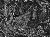
- the MgZn 2 phase has a low roughness (surface roughness Sa is 50 nm or less), it has a higher specular reflectance and diffuse reflection than a structure having a high roughness (surface roughness Sa is about 100 to 300 nm) around it. The rate is low.
- the MgZn 2 phase having a high specular reflectance looks white, while the structure having a low specular reflectance and a high diffuse reflectance looks black (see FIGS. 1 to 2).
- the MgZn 2 phase is developed into a coarse dendrite on the Zn—Al—Mg alloy layer having high planar corrosion resistance and sacrificial corrosion resistance, and the surface roughness Sa of the surface of the Zn—Al—Mg alloy layer is 50 nm or less.
- a predetermined amount of dendrite-like MgZn 2 phase is present and a large number of coarse dendrite-like MgZn 2 phases are present with a surface roughness Sa of 50 nm or less, a beautiful spangle pattern is formed.
- the spangle pattern in the hot-dip galvanized layer, the post-plating layer, etc. is usually formed by Zn crystal grains, but in the present disclosure, the spangle pattern in the Zn—Al—Mg alloy layer is the light of the MgZn 2 phase. It is formed by the difference in color due to the difference in reflectance of.
- the plated steel material of the present disclosure is a plated steel material having a beautiful spangle appearance and excellent flat corrosion resistance and sacrificial corrosion resistance due to the above configuration. Further, since the plated steel material of the present disclosure is excellent in sacrificial anticorrosion property, it is possible to realize cost reduction by omitting end face repair.
- the base steel material to be plated will be described.
- the shape of the base steel is not particularly limited.
- the base steel materials include steel pipes, civil engineering and building materials (fence culverts, corrugated pipes, drainage ditches, sand-prevention plates, bolts, wire mesh, guardrails, waterproof walls, etc.), household appliances (air conditioner outdoor unit housings, etc.) Examples include molded base steel materials such as body parts) and automobile parts (undercarriage members, etc.).
- various plastic working methods such as press working, roll forming, and bending can be used.
- the base steel is, for example, general steel, preplated steel, Al killed steel, ultra-low carbon steel, high carbon steel, various high tension steels, some high alloy steels (steel containing reinforced elements such as Ni and Cr), etc.
- the base steel material is not particularly limited in terms of conditions such as a method for manufacturing the base steel material and a method for manufacturing the base steel sheet (hot rolling method, pickling method, cold rolling method, etc.).
- hot-rolled steel plates, hot-rolled steel strips, cold-rolled steel plates, and cold-rolled steel strips described in JIS G 3302 (2010) can also be applied.
- the base steel material may be a pre-plated pre-plated steel material.
- the pre-plated steel material is obtained, for example, by an electrolytic treatment method or a substitution plating method.
- a pre-plated steel material is obtained by immersing the base steel material in a sulfuric acid bath or a chloride bath containing metal ions of various pre-plating components and performing an electrolytic treatment.
- the substitution plating method a base steel material is immersed in an aqueous solution containing metal ions of various pre-plating components and whose pH is adjusted with sulfuric acid, and the metal is substituted and precipitated to obtain a pre-plating steel material.
- a pre-Ni plated steel material can be mentioned.
- the plating layer includes a Zn—Al—Mg alloy layer.
- the plating layer may include an Al—Fe alloy layer in addition to the Zn—Al—Mg alloy layer.
- the Al—Fe alloy layer is provided between the base steel material and the Zn—Al—Mg alloy layer.
- the plating layer may have a single-layer structure of a Zn—Al—Mg alloy layer, or may have a laminated structure including a Zn—Al—Mg alloy layer and an Al—Fe alloy layer.
- the Zn—Al—Mg alloy layer may be a layer constituting the surface of the plating layer.
- an oxide film of a plating layer constituent element may be formed on the surface of the plating layer by about 50 nm, it is considered that it is thin with respect to the thickness of the entire plating layer and does not form the main body of the plating layer.
- the amount of the plating layer adhered is preferably 20 to 300 g / m 2 per side.
- the adhesion amount of the plating layer is 20 g / m 2 or more, the corrosion resistance of the flat surface portion and the sacrificial corrosion resistance can be ensured.
- the adhesion amount of the plating layer is set to 300 g / m 2 or less, it is possible to suppress appearance defects such as a drooping pattern of the plating layer.
- the thickness of the Zn—Al—Mg alloy layer is, for example, 2 ⁇ m or more and 95 ⁇ m or less (preferably 5 ⁇ m or more and 75 ⁇ m or less).
- the thickness of the entire plating layer is, for example, about 100 ⁇ m or less. Since the thickness of the entire plating layer depends on the plating conditions, the upper and lower limits of the thickness of the entire plating layer are not particularly limited. For example, the thickness of the entire plating layer is related to the viscosity and specific density of the plating bath in the usual hot-dip plating method. Furthermore, the plating amount is adjusted by the drawing speed of the base steel material and the strength of the wiping. Therefore, it can be considered that the lower limit of the thickness of the entire plating layer is about 2 ⁇ m.
- the upper limit of the thickness of the plating layer that can be produced by the hot-dip plating method is about 95 ⁇ m. Since the thickness of the plating layer can be freely changed depending on the drawing speed from the plating bath and the wiping conditions, the formation of a plating layer having a thickness of 2 to 95 ⁇ m is not particularly difficult to manufacture.
- the thickness of the Al—Fe alloy layer is, for example, 0 ⁇ m or more and 5 ⁇ m or less. That is, the Al—Fe alloy layer does not have to be formed.
- the thickness of the Al—Fe alloy layer is preferably 0.05 ⁇ m or more and 5 ⁇ m or less from the viewpoint of enhancing the adhesion of the plating layer (specifically, the Zn—Al—Mg alloy layer) and ensuring processability.
- a plating layer having a chemical composition specified in the present disclosure is formed by a hot-dip plating method
- an Al—Fe alloy layer having a diameter of 100 nm or more is formed between the base steel material and the Zn—Al—Mg alloy layer.
- the lower limit of the thickness of the Al—Fe alloy layer is not particularly limited, and it has been found that the Al—Fe alloy layer is inevitably formed when the hot-dip plating layer containing Al is formed. There is. From experience, it is empirically determined that around 100 nm is the thickness when the formation of the Al—Fe alloy layer is suppressed most, and is the thickness that sufficiently secures the adhesion between the plating layer and the base steel material.
- the Al concentration is high unless special measures are taken, it is difficult to form an Al—Fe alloy layer thinner than 100 nm by the hot-dip plating method. However, even if the thickness of the Al—Fe alloy layer is less than 100 nm, and even if the Al—Fe alloy layer is not formed, it is presumed that the plating performance is not significantly affected.
- the thickness of the Al—Fe alloy layer exceeds 5 ⁇ m, the Al component of the Zn—Al—Mg alloy layer formed on the Al—Fe alloy layer is insufficient, and further, the adhesion and workability of the plating layer are insufficient. Tends to get extremely worse. Therefore, the thickness of the Al—Fe alloy layer is preferably limited to 5 ⁇ m or less.
- the Al—Fe alloy layer is also closely related to the Al concentration and the Sn concentration, and generally, the higher the Al concentration and the Sn concentration, the faster the growth rate tends to be.
- the thickness of the Zn—Al—Mg alloy layer and the Al—Fe alloy layer is measured as follows. After embedding the sample in resin, it is ground and the SEM reflected electron image of the cross section of the plating layer (cut surface along the thickness direction of the plating layer) (however, the magnification is 5000 times, the size of the field of view: 50 ⁇ m in length ⁇ 200 ⁇ m in width). In the field of view where the Al—Fe alloy layer can be visually recognized.), The thickness is measured at any five points of the identified Al—Fe alloy layer. Then, the arithmetic mean of the five points is taken as the thickness of the interfacial alloy layer.
- the Al—Fe alloy layer may be formed on the surface of the base steel material (specifically, between the base steel material and the Zn—Al—Mg alloy layer), and the Al 5 Fe phase is the main phase layer as a structure. be.
- the Al—Fe alloy layer is formed by mutual atomic diffusion between the base steel material and the plating bath. In the plating layer containing an Al element, an Al—Fe alloy layer is likely to be formed. Since Al at a certain concentration or higher is contained in the plating bath, the Al 5 Fe phase is formed most. However, atomic diffusion takes time, and there is a portion where the Fe concentration becomes high in the portion close to the base steel material.
- the Al—Fe alloy layer may partially contain a small amount of AlFe phase, Al 3 Fe phase, Al 5 Fe 2 phase, and the like. Further, since Zn is also contained in the plating bath at a constant concentration, a small amount of Zn is also contained in the Al—Fe alloy layer.
- the corrosion resistance referred to here is the corrosion resistance in a portion that is not affected by welding.
- Si when Si is contained in the plating layer, Si is particularly easily incorporated into the Al—Fe alloy layer and may become an Al—Fe—Si intermetallic compound phase.
- the intermetallic compound phase to be identified includes an AlFeSi phase, and isomers include ⁇ , ⁇ , q1, q2-AlFeSi phases and the like. Therefore, these AlFeSi phases and the like may be detected in the Al—Fe alloy layer.
- the Al—Fe alloy layer containing these AlFeSi phases and the like is also referred to as an Al—Fe—Si alloy layer. Since the thickness of the Al—Fe—Si alloy layer is smaller than that of the Zn—Al—Mg alloy layer, the effect on the corrosion resistance of the entire plating layer is small.
- the structure of the Al—Fe alloy layer may change depending on the amount of pre-plating adhered. Specifically, when the pure metal layer used for pre-plating remains around the Al—Fe alloy layer, an intermetal compound phase in which the constituent components of the Zn—Al—Mg alloy layer and the pre-plating component are bonded (for example, When an Al 3 Ni phase, etc.) forms an alloy layer, when an Al—Fe alloy layer in which a part of Al atom and Fe atom is replaced with another atom is formed, or one of Al atom, Fe atom and Si atom.
- an Al—Fe—Si alloy layer is formed in which the portion is replaced with another atom.
- these alloy layers are also smaller in thickness than the Zn—Al—Mg alloy layer, they have a small effect on the corrosion resistance of the entire plating layer.
- the Al—Fe alloy layer is a layer that includes the alloy layers of the above-mentioned various aspects in addition to the alloy layer mainly composed of the Al 5 Fe phase.
- the Al—Ni—Fe alloy layer is formed as the Al—Fe alloy layer. Since the thickness of the Al—Ni—Fe alloy layer is smaller than that of the Zn—Al—Mg alloy layer, the effect on the corrosion resistance of the entire plating layer is small.
- the chemical composition of the Al—Fe alloy layer is Fe: 25 to 35%, Al: 65 to 75%, Zn: 5% or less. And the balance: a composition containing impurities can be exemplified.
- the thickness of the Zn—Al—Mg alloy layer is usually thicker than that of the Al—Fe alloy layer, the contribution of the Al—Fe alloy layer to the corrosion resistance of the flat surface portion of the plated steel material is that of the Zn—Al—Mg alloy layer. It is small in comparison.
- the Al—Fe alloy layer contains Al and Zn, which are corrosion resistant elements, at a certain concentration or higher. Therefore, the Al—Fe alloy layer has a sacrificial anticorrosion ability and a corrosion barrier effect on the base steel material to some extent.
- the Zn—Al—Mg alloy layer on the Al—Fe alloy layer is precisely removed by cutting from the surface of the plating layer by end milling or the like, and a corrosion test is performed.
- the corrosion resistance of the Al—Fe alloy layer alone can be evaluated by applying. Since the Al—Fe alloy layer contains an Al component and a small amount of Zn component, when the Al—Fe alloy layer is provided, red rust is generated in dots, the Al—Fe alloy layer is not present, and the base steel material is exposed. As in the case, the entire surface does not become red rust.
- the thickness of the Al—Fe alloy layer is preferably 0.05 ⁇ m or more.
- the thickness is preferably a certain thickness or less.
- the thickness of the Al—Fe alloy layer is preferably 5 ⁇ m or less. When the thickness of the Al—Fe alloy layer is 5 ⁇ m or less, cracks and powdering amounts generated starting from the plated Al—Fe alloy layer are reduced by a V-bending test or the like, and workability is improved.
- the thickness of the Al—Fe alloy layer is more preferably 2 ⁇ m or less.
- the chemical composition of the plating layer is mass%.
- Zn Over 65.0%, Al: More than 5.0% to less than 25.0%, Mg: more than 3.0% to less than 12.5%, Sn: 0% to 3.00%, Bi: 0% to less than 5.0%, In: 0% to less than 2.0%, Ca: 0% to 3.0%, Y: 0% to 0.5%, La: 0% to less than 0.5%, Ce: 0% to less than 0.5%, Si: 0% to less than 2.5%, Cr: 0% to 0.25%, Ti: 0% to 0.25%, Ni: 0% to 0.25%, Co: 0% -0.25%, V: 0% to 0.25%, Nb: 0% to 0.25%, Cu: 0% to 0.25%, Mn: 0% to 0.25%, Fe: 0% to 5.0%, Sr: 0% to less than 0.5%, Sb: 0% to less than 0.5%, Pb: 0% to less than 0.5%, B: A chemical composition consisting of 0% to less than 0.
- the chemical composition of this plating layer is the average chemical composition of the entire plating layer (when the plating layer has a single layer structure of a Zn—Al—Mg alloy layer, the average chemical composition of the Zn—Al—Mg alloy layer, the plating layer. Is the average chemical composition of the total of the Al—Fe alloy layer and the Zn—Al—Mg alloy layer in the case of the laminated structure of the Al—Fe alloy layer and the Zn—Al—Mg alloy layer).
- Zn is an element necessary for obtaining sacrificial corrosion resistance in addition to corrosion resistance on a flat surface.
- the Zn concentration is taken into consideration in terms of the atomic composition ratio, since it is a plating layer composed of elements having a low specific gravity such as Al and Mg, it is necessary that the Zn concentration is mainly Zn even in the atomic composition ratio. Therefore, the Zn concentration is set to more than 65.0%.
- the Zn concentration is preferably 70% or more.
- the upper limit of the Zn concentration is the concentration that is the balance other than the elements and impurities other than Zn.
- Al is an essential element for forming Al crystals and ensuring both corrosion resistance and sacrificial corrosion resistance on a flat surface.
- Al is an essential element for enhancing the adhesion of the plating layer and ensuring processability. Therefore, the lower limit of the Al concentration is set to exceed 5.0% (preferably 10.0% or more).
- the upper limit of the Al concentration is set to less than 25.0% (preferably 23.0% or less).
- Mg is an essential element for ensuring both corrosion resistance on a flat surface and sacrificial corrosion resistance. Further, Mg is an essential element for precipitating the developed coarse dendrite-like MgZn 2 phase. Therefore, the lower limit of the Mg concentration is set to exceed 3.0% (preferably more than 5.0%). On the other hand, as the Mg concentration increases, the workability tends to deteriorate. Therefore, the upper limit of the Mg concentration is less than 12.5% (preferably 10.0% or less).
- Sn is an element that forms the Mg 2 Sn phase, which is a water-soluble tissue, and imparts high sacrificial anticorrosion properties. Therefore, the lower limit of the Sn concentration is preferably more than 0% (preferably 0.05% or more, more preferably 0.10% or more). On the other hand, as the Sn concentration increases, the corrosion resistance of the flat surface portion tends to deteriorate. Therefore, the upper limit of the Sn concentration is 3.00% or less (preferably 2.50% or less).
- Bi is an element that contributes to sacrificial anticorrosion. Therefore, the lower limit of the Bi concentration is preferably more than 0% (preferably 0.1% or more, more preferably 3.0% or more). On the other hand, as the Bi concentration increases, the corrosion resistance of the flat surface portion tends to deteriorate. Therefore, the upper limit of the Bi concentration is set to less than 5.0% (preferably 4.8% or less).
- the lower limit of the In concentration is preferably more than 0% (preferably 0.1% or more, more preferably 1.0% or more).
- the upper limit of the In concentration is set to less than 2.0% (preferably 1.8% or less).
- Ca is an element that can adjust the optimum amount of Mg elution to impart corrosion resistance and sacrificial corrosion resistance to the flat surface portion. Therefore, the lower limit of the Ca concentration is preferably more than 0% (preferably 0.05% or more). On the other hand, as the Ca concentration increases, the corrosion resistance and processability of the flat surface portion tend to deteriorate. Therefore, the upper limit of the Ca concentration is 3.0% or less (preferably 1.0% or less).
- Y is an element that contributes to sacrificial anticorrosion. Therefore, the lower limit of the Y concentration is preferably more than 0% (preferably 0.1% or more). On the other hand, as the Y concentration increases, the corrosion resistance of the flat surface portion tends to deteriorate. Therefore, the upper limit of the Y concentration is 0.5% or less (preferably 0.3% or less).
- La and Ce are elements that contribute to sacrificial anticorrosion. Therefore, the lower limit values of the La concentration and the Ce concentration are preferably more than 0% (preferably 0.1% or more), respectively. On the other hand, as the La concentration and the Ce concentration increase, the corrosion resistance of the flat surface portion tends to deteriorate. Therefore, the upper limits of the La concentration and the Ce concentration are each set to less than 0.5% (preferably 0.4% or less).
- Si is an element that suppresses the growth of the Al—Fe alloy layer and contributes to the improvement of corrosion resistance. Therefore, the Si concentration is preferably 0% or more (preferably 0.05% or more, more preferably 0.1% or more). On the other hand, as the Si concentration increases, the corrosion resistance, sacrificial corrosion resistance, and processability of the flat surface portion tend to deteriorate. Therefore, the upper limit of the Si concentration is set to less than 2.5%. In particular, from the viewpoint of the corrosion resistance of the flat surface portion and the sacrificial corrosion resistance, the Si concentration is preferably 2.4% or less, more preferably 1.8% or less, still more preferably 1.2% or less.
- ⁇ Cr, Ti, Ni, Co, V, Nb, Cu and Mn 0% to 0.25%> Cr, Ti, Ni, Co, V, Nb, Cu and Mn are elements that contribute to sacrificial anticorrosion. Therefore, the lower limit of the concentrations of Cr, Ti, Ni, Co, V, Nb, Cu and Mn is preferably 0% or more (preferably 0.05% or more, more preferably 0.1% or more). On the other hand, when the concentrations of Cr, Ti, Ni, Co, V, Nb, Cu and Mn increase, the corrosion resistance of the flat surface portion tends to deteriorate. Therefore, the upper limit of the concentrations of Cr, Ti, Ni, Co, V, Nb, Cu and Mn is set to 0.25% or less, respectively. The upper limit of the concentrations of Cr, Ti, Ni, Co, V, Nb, Cu and Mn is preferably 0.22% or less.
- Sr, Sb, Pb and B 0% to less than 0.5%> Sr, Sb, Pb and B are elements that contribute to sacrificial anticorrosion. Therefore, the lower limit of the concentrations of Sr, Sb, Pb and B is preferably more than 0% (preferably 0.05% or more, more preferably 0.1% or more). On the other hand, when the concentrations of Sr, Sb, Pb and B increase, the corrosion resistance of the flat surface portion tends to deteriorate. Therefore, the upper limit of the concentrations of Sr, Sb, Pb and B is set to less than 0.5%, respectively.
- Impurities refer to components contained in raw materials or components mixed in the manufacturing process and not intentionally contained. For example, components other than Fe may be mixed in a small amount as impurities in the plating layer due to mutual atomic diffusion between the base steel material and the plating bath.
- the chemical composition of the plating layer is measured by the following method. First, an acid solution obtained by exfoliating and dissolving the plating layer with an acid containing an inhibitor that suppresses corrosion of the base steel material is obtained. Next, by measuring the obtained acid solution by ICP analysis, the chemical composition of the plating layer (when the plating layer has a single layer structure of a Zn—Al—Mg alloy layer, the chemical composition of the Zn—Al—Mg alloy layer When the plating layer has a laminated structure of an Al—Fe alloy layer and a Zn—Al—Mg alloy layer, the total chemical composition of the Al—Fe alloy layer and the Zn—Al—Mg alloy layer) can be obtained.
- the acid type is not particularly limited as long as it is an acid that can dissolve the plating layer.
- the pre-plated component is also detected.
- a pre-Ni plated steel material not only Ni in the plating layer but also Ni in the pre-Ni plating is detected in the ICP analysis.
- a pre-plated steel material having a Ni adhesion amount of 1 g / m 2 to 3 g / m 2 is used as a base steel material, even if the Ni concentration contained in the plating layer is 0%, the Ni concentration Is detected as 0.1 to 15%.
- the pre-Ni plated steel material when used as the base steel material, when the base steel material is immersed in the plating bath, a small amount of Ni in the pre-Ni plating layer is dissolved in the plating bath. Therefore, the Ni concentration in the plating bath is 0.02 to 0.03% higher than the Ni concentration in the built-in plating bath. Therefore, when the pre-Ni plated steel material is used, the Ni concentration in the plated layer is increased by 0.03% at the maximum.
- the method for determining whether or not the base steel material is a pre-Ni plated steel material is as follows. From the target steel material, a sample whose cross section cut along the thickness direction of the plating layer is the measurement surface is collected. The Ni concentration is measured by performing a line analysis on the measurement surface of the sample near the interface between the plating layer and the base steel material in the steel material using an electron probe microanalyzer (FE-EPMA).
- the measurement conditions are an acceleration voltage of 15 kV, a beam diameter of about 100 nm, an irradiation time of 1000 ms per point, and a measurement pitch of 60 nm.
- the measurement distance may be any distance as long as it can be confirmed whether or not the Ni concentration is concentrated at the interface between the plating layer and the base steel material in the steel material. Then, if the Ni concentration is concentrated at the interface between the plated layer and the base steel material in the steel material, it is determined whether or not the base steel material is a pre-plated steel material.
- the Ni concentration is 0.28 (0.25% (upper limit of the Ni concentration in the plated layer) + 0.03%)% or more 15 by ICP analysis.
- the Ni concentration of the plating layer is considered to be 0%.
- the plated layer contains 0.25% Ni (the upper limit of the Ni concentration in the plated layer). ) Is considered to be included.
- the components of the plating layer were measured using only the ICP analysis method, but by using the glow discharge emission spectrometry (quantitative GDS) in combination with the ICP analysis method, the Ni concentration in the plating layer It is possible to analyze.
- the Ni concentration of the plating layer is ICP Ni concentration ⁇ 0.03%
- the formula B when the formula B is satisfied, the plating layer It is determined that the Ni concentration is 0%, the Ni concentration of the plating layer is 0.25% when the formula C is satisfied, and the Ni concentration of the plating layer is the ICP Ni concentration -15% when the formula D is satisfied.
- Formula A ICP Ni concentration ⁇ 0.28 Equation B; 0.28 ⁇ ICP Ni concentration ⁇ 15
- Formula C 15 ⁇ ICP Ni concentration ⁇ 15.25 Formula D; 15.25 ⁇ ICP Ni concentration
- the surface of the Zn—Al—Mg alloy layer has a dendrite-like MgZn 2 phase having a surface roughness Sa of 50 nm or less.
- the area ratio of the dendrite-like MgZn 2 phase having a surface roughness Sa of 50 nm or less is 30% or more and 80% or less within the range of the observation field of view of 5 mm 2 .
- the number of coarse dendrite-like MgZn 2 phases (dendrite-like MgZn 2 phases having an area of 0.1 mm 2 or more) among the dendrite-like Mg Zn 2 phases having a surface roughness Sa of 50 nm or less is within the range of the observation field of view 25 mm 2 . 5 or more and 100 or less.
- the dendrite-shaped MgZn 2 phase is composed of the MgZn 2 phase, and has a primary arm (that is, a main shaft) and a secondary arm (that is, a secondary shaft) that grows in a branch shape from the primary arm. It is a structure-like structure (see FIG. 1).
- Arm1 indicates a primary arm
- Arm2 indicates a secondary arm.
- the dendrite-like MgZn 2 phase may include a tertiary arm that grows in a branch shape from the secondary arm and a quaternary arm that grows in a branch shape from the tertiary arm.
- the MgZn 2 phase having a surface roughness Sa of more than 50 nm has a low specular reflectance and does not contribute to imparting a spangle appearance. If the area ratio of the MgZn 2 -phase having a surface roughness Sa of 50 nm or less is too low, the region where the specular reflectance is high is reduced. On the other hand, if the area ratio of the MgZn 2 -phase having a surface roughness Sa of 50 nm or less is too high, the region where the specular reflectance is high increases.
- the area ratio of the MgZn 2 phase having a surface roughness Sa of 50 nm or less is set to 30% or more and 80% or less within the range of the observation field of view of 5 mm 2 .
- a fine dendrite-like MgZn 2 phase having an area of 0.1 mm 2 or less cannot be recognized as a spangle appearance due to a specular reflectance difference. If the amount of coarse dendrite-like MgZn 2 phase is too small, the amount of dendrite-like MgZn 2 phase that can be recognized as a spangle appearance is small. On the other hand, if the number of coarse dendrite-like MgZn 2 phases is too large, the number of dendrite-like MgZn 2 phases that can be recognized as a spangle appearance increases. That is, if the coarse dendrite-like MgZn 2 phase is too small or too large, it cannot be recognized as a spangle appearance due to a specular reflectance difference.
- the number of coarse dendrite-like MgZn 2 phases is 5 or more and 100 or less within the range of the observation field of view 25 mm 2 .
- the area ratio of the dendrite-like MgZn 2 phase having a surface roughness Sa of 50 nm or less is preferably 35% or more and 75% or less, preferably 40% or more and 70% within the range of the observation field of view of 5 mm 2 .
- the following is more preferable.
- the number of coarse dendrite-like MgZn 2 phases is preferably 10 or more and 90 or less, and more preferably 15 or more and 85 or less within the range of the observation field of view of 25 mm 2 .
- the measuring method is as follows.
- a sample whose surface is 1 cm x 1 cm square is collected from the plated steel material to be measured. However, the sample is taken from a place where there is no defect in the plating layer, except near the punched end face of the plated steel material (2 mm from the end face).
- the surface of the plating layer (specifically, the Zn—Al—Mg alloy layer) of the sample is observed with an optical microscope (magnification 5 times).
- the observation field of view is 5 mm 2 .
- the surface roughness Sa of the dendrite-like MgZn 2 -phase is measured with an atomic force microscope (AFM) in an observation field of 5 mm 2 .
- the surface roughness Sa at any five points in the primary arm and the secondary arm of the dendrite-like MgZn 2 phase is measured by an atomic force microscope (AFM), respectively.
- the arithmetic mean value of the surface roughness Sa at a total of 10 places is obtained.
- the measurement conditions of the atomic force microscope (AFM) are as follows.
- the area ratio of the dendrite-like MgZn 2 phase having a surface roughness Sa of 50 nm or less is obtained in an observation field of view of 5 mm 2 . This operation is performed in 5 places to obtain the calculated average value of the area ratio.
- This arithmetic mean value is defined as "the area ratio of the dendrite-like MgZn 2 phase having a surface roughness Sa of 50 nm or less".
- the area of one dendrite-like MgZn 2 phase having a surface roughness Sa of 50 nm or less is the root and tip of the primary arm and the nth-order arm located outside the dendrite-like MgZn 2 phase (specifically). Is the area of the region surrounding the outer periphery of the dendrite-like MgZn 2 phase passing through the tips of the secondary arm to the quaternary arm (see A in FIG. 2).
- the number of coarse dendrite-like MgZn 2 phases among the dendrite-like MgZn 2 phases having a surface roughness Sa of 50 nm or less is counted in 5 observation fields of view 5 mm 2 (that is, within the range of the observation field of view 25 mm 2 ). .. This number is defined as "the number of coarse dendrite-like MgZn 2 phases (dendrite-like MgZn 2 phases having an area of 0.1 mm 2 or more) within the observation field of view 25 mm 2 ".
- the plated steel material of the present disclosure is obtained by forming a plating layer having the above-mentioned predetermined chemical composition and metal structure on the surface (that is, one side or both sides) of the base steel sheet as a base steel material by a hot-dip plating method.
- the hot-dip plating process is performed under the following conditions.
- the outline of the manufacturing method is as follows. First, the surface to be plated of the base steel sheet is brush-ground so that the specific surface area of the surface to be plated of the base steel sheet is more than 100 to 150%.
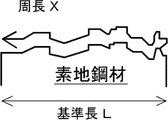
- the specific surface area is the ratio of the actual surface area to the completely flat surface. A detailed definition of the specific surface area will be described later for convenience of explanation.
- the surface to be plated is referred to as the surface of the base steel sheet forming the plating layer.
- the brush-ground base steel sheet is immersed in a plating bath, the base steel sheet is pulled up from the plating bath, and then the average cooling rate in the temperature range from the plating bath temperature to 410 ° C. and the temperature range from 410 ° C. to 380 ° C. Cool at an average cooling rate of 1.5 times or more and 5 times or less of.
- the temperature range from 410 ° C. to 380 ° C. is cooled at an average cooling rate of 0.5 ° C./s or more and 9 ° C./s or less.
- the temperature range from 380 ° C. to 300 ° C. is cooled at an average cooling rate of 4 times or more and 15 times or less the average cooling rate in the temperature range of 410 ° C. to 380 ° C.
- an example of the method for manufacturing the plated steel material of the present disclosure is as follows. That is, the surface to be plated of the base steel sheet is brush-ground, and the specific surface area of the surface to be plated of the base steel sheet is set to more than 100% to 150%.
- the specific surface area of the surface to be plated of the base steel sheet is preferably 105 to 150% before grinding by brush grinding.
- Brush grinding is performed with, for example, a nylon brush containing abrasive grains such as alumina, silicon carbide, and diamond powder.
- the average cooling rate in the temperature range from the plating bath temperature to 410 ° C is A
- the average cooling rate in the temperature range from 410 ° C to 380 ° C is B
- the average cooling rate in the temperature range from 380 ° C to 300 ° C is C.
- the base steel plate is cooled under the condition that the formula (1): A ⁇ 1.5 ⁇ B, the formula (2): B ⁇ 9 ° C./s, and the formula (3): C ⁇ 4 ⁇ B are satisfied.
- the upper limit of the average cooling rate A in the temperature range from the plating bath temperature to 410 ° C. is set to 5 times or less of the average cooling rate B from the viewpoint of appearance defects such as wind patterns.
- the lower limit of the average cooling rate B in the temperature range from 410 ° C. to 380 ° C. is set to 0.5 ° C./s or more from the viewpoint of suppressing the entrainment of the plating layer in the top roll due to insufficient cooling during manufacturing.
- the upper limit of the average cooling rate C in the temperature range from 380 ° C. to 300 ° C. is set to 15 times or less of the average cooling rate B from the viewpoint of suppressing appearance defects such as uneven patterns.
- the plating bath temperature is preferably set to the melting point of the plating bath + 20 ° C. or higher.
- the specific surface area of the surface to be plated of the base steel sheet is approximately 100%.
- the specific surface area of the surface to be plated is set to more than 100 to 150% by brush grinding.
- the specific surface area of the surface to be plated of the base steel sheet before the hot-dip plating treatment exceeds 150%. Therefore, the specific surface area of the surface to be plated is set to more than 100 to 150% by brush grinding.
- the specific surface area of the pre-plated steel sheet is set to more than 100 to 150%. Therefore, the specific surface area of the base steel sheet before pre-plating may be appropriately adjusted according to the plating amount of pre-plating. That is, when the base steel sheet is a pre-plated steel sheet, the specific surface area of the base steel sheet after pre-plating is set to more than 100 to 150% by brush-grinding the surface to be plated of the base steel sheet before pre-plating.
- the specific method for measuring the specific surface area is as follows. First, a sample having a surface of 1 cm ⁇ 1 cm square is collected from the base steel material to be measured. However, the sample shall be collected from a place other than the vicinity of the punched end face of the base steel material (2 mm from the end face). Next, the peripheral length X of the surface to be plated of the base steel material of the sample is measured by observing the cross section of the base steel material by a scanning electron microscope (that is, observing the cross section cut along the thickness direction of the base steel material).
- the reference length L and the circumference X are defined as follows (see FIG. 3).
- -Reference length L Horizontal length of the field of view when the surface to be plated of the base steel material is observed at a magnification of 10000 times-Perimeter X: Length of tracing the surface to be plated of the base steel material in the above field of measurement Note that the measurement target When is a plated steel material, the reference length L and the peripheral length X are measured by observing the interface between the plated layer and the base steel material.
- the specific surface area is calculated by the above formula. Then, the above operation is performed at arbitrary three places, and the calculated average value of the obtained specific surface area is calculated. This calculated average value is referred to as "specific surface area”.
- the temperature range from the plating bath temperature to 410 ° C. is primarily cooled at an average cooling rate satisfying the formula (1) to form the plating layer.
- the average cooling rate satisfying the formula (1) is, for example, air cooling with a large wind speed.
- a coarse dendrite-like MgZn 2 phase appears on the surface of the Zn—Al—Mg alloy layer, and the area ratio of the dendrite-like MgZn 2 phase having a surface roughness Sa of 50 nm or less is satisfied, and the coarse dendrite-like MgZn 2 phase is satisfied.
- the average cooling rate satisfying the formula (2) is, for example, air cooling with a small wind speed.
- a dendrite-like MgZn 2 having a surface roughness Sa of 50 nm or less is sufficiently precipitated around the developed dendrite - like Al phase.
- the temperature range from 410 ° C to 380 ° C is secondary cooling at an average cooling rate of 1 to 9 ° C / s. Is preferable.
- 410 ° C. is a temperature range of about ⁇ 50 ° C., which is the plating solidification start temperature.
- the plating solidification start temperature can be measured by the following method.
- the temperature range from 380 ° C to 300 ° C at an average cooling rate that satisfies the formula (3), it is possible to prevent plating from wrapping around the top roll and suppress appearance defects such as wind prints.
- the average cooling rate satisfying the formula (3) is, for example, mist cooling.
- the Al—Fe alloy layer formed between the base steel plate and the base steel sheet rapidly forms and grows in less than 1 second immediately after immersion in the plating.
- the growth rate is higher when the plating bath temperature is high, and is even higher when the immersion time in the plating bath is long.
- the plating bath temperature is lower than 500 ° C., the plating bath hardly grows, so it is better to reduce the immersion time or immediately move from solidification to the cooling process.
- the reheating temperature of the plating layer is set to a temperature range immediately above the melting point of the plating bath so that the Al—Fe alloy layer does not grow excessively.
- the plated steel material of the present disclosure may form a film on the plated layer.
- the film can form one layer or two or more layers.
- Examples of the type of the film directly above the plating layer include a chromate film, a phosphate film, and a chromate-free film. Chromate treatment, phosphate treatment, and chromate-free treatment for forming these films can be performed by known methods.
- Chromate treatment includes electrolytic chromate treatment that forms a chromate film by electrolysis, reaction-type chromate treatment that forms a film using the reaction with the material, and then rinses away excess treatment liquid, and the treatment liquid is applied to the object to be coated. There is a coating type chromate treatment that dries to form a film without washing with water. Any process may be adopted.
- electrolytic chromate treatment electrolytic chromate treatment using chromic acid, silica sol, resin (acrylic resin, vinyl ester resin, vinyl acetate acrylic emulsion, carboxylated styrene butadiene latex, diisopropanolamine modified epoxy resin, etc.) and hard silica is performed. It can be exemplified.
- Examples of the phosphate treatment include zinc phosphate treatment, zinc phosphate calcium treatment, and manganese phosphate treatment.
- Chromate-free treatment is particularly suitable because it does not have a burden on the environment.
- Chromate-free treatment includes electrolytic chromate-free treatment that forms a chromate-free film by electrolysis, reaction-type chromate-free treatment that forms a film by reacting with a material, and then rinses away excess treatment liquid.
- organic resin films may be provided on the film directly above the plating layer.
- the organic resin is not limited to a specific type, and examples thereof include polyester resin, polyurethane resin, epoxy resin, acrylic resin, polyolefin resin, and modified products of these resins.
- the modified product is a reaction of a reactive functional group contained in the structure of these resins with another compound (monomer, cross-linking agent, etc.) containing a functional group capable of reacting with the functional group. Refers to resin.
- organic resin one kind or two or more kinds of organic resins (not modified) may be mixed and used, or at least one kind of other organic resin in the presence of at least one kind of organic resin.
- the organic resin obtained by modifying the organic resin of the above may be used alone or in combination of two or more.
- the organic resin film may contain any coloring pigment or rust preventive pigment.
- Water-based products can also be used by dissolving or dispersing in water.
- Example 2 A plating bath was built in the air after melting the ingot in a vacuum melting furnace using a predetermined amount of pure metal ingot so that the plating layer having the chemical composition shown in Tables 1 and 2 could be obtained.
- a batch type hot-dip plating device was used to prepare the plated steel material.
- As the base steel material a general hot-rolled carbon steel sheet (C concentration ⁇ 0.1%) having a plate thickness of 2.3 mm was used, and degreasing and pickling were carried out immediately before the plating process. Then, brush grinding was performed on the surface to be plated of the base steel material with a brush roll containing abrasive grains so as to have the specific surface area shown in Tables 1 and 2.
- a pre-Ni plated steel sheet obtained by subjecting a general hot-rolled carbon steel sheet having a plate thickness of 2.3 mm to pre-Ni plating was used as the base steel material.
- the amount of Ni adhered was 1 to 3 g / m 2 .
- pre-Ni plating was performed after brush grinding.
- "pre-Ni" is written in the "base steel material” column in the table, and the Ni concentration in the plating bath is written in parentheses in the Ni concentration column. Was written.
- the same reduction treatment method was carried out for the base steel material in the steps up to the time of immersion in the plating bath. That is, the base steel material was heated from room temperature to 800 ° C. by energization heating under an environment of N2 - H2 (5%) (dew point -40 ° C or less, oxygen concentration less than 25 ppm), held for 60 seconds, and then N2 .
- the plating bath temperature was cooled to + 10 ° C. by spraying gas, and the mixture was immediately immersed in the plating bath.
- the immersion time in the plating bath was the time shown in the table.
- the N2 gas wiping pressure was adjusted to prepare a plated steel sheet so that the plating thickness was 30 ⁇ m ( ⁇ 1 ⁇ m).
- the plating bath temperature was basically a melting point of + 20 ° C., and the temperature was further raised at some levels for plating.
- the plating bath immersion time was 2 seconds.
- a plating layer was obtained by a cooling process in which the average cooling rates of the following 1st to 3rd stages shown in Tables 1 and 2 were set as the conditions shown in Tables 1 and 2.
- ⁇ First-stage average cooling rate average cooling rate in the temperature range from the plating bath temperature to 410 ° C
- Second-stage average cooling rate average cooling rate in the temperature range from 410 ° C to 380 ° C
- third-stage average cooling rate Average cooling rate in the temperature range from 380 ° C to 300 ° C
- the plated steel sheet was bent by 90 ° V, a cellophane tape having a width of 24 mm was pressed against the V-bent valley portion and pulled apart, and powdering was visually evaluated.
- the tape to which the powdering peeling powder did not adhere was evaluated as "A”
- the tape to which the powder was slightly adhered was evaluated as "A-”
- the tape to which the powder was slightly adhered was evaluated as "NG”.
- the primary cooling is performed at an average cooling rate that does not satisfy the formula (1): A ⁇ 1.5 ⁇ B, and the formula (3): C ⁇ 4 ⁇ B is satisfied.
- the tertiary cooling was performed at a non-average cooling rate, it can be seen that the spangle pattern is difficult to see because the surface texture of the plating layer deteriorated due to the mist cooling.
- the comparative example (Test No. 74) in which the tertiary cooling was performed at a non-average cooling rate, it can be seen that the spangle pattern is difficult to see because the surface texture of the plating layer deteriorated due to the mist cooling.
- the Ni concentration of the plating layer in the example using the pre-Ni plated steel sheet is 0.28% or more and 15% or less, the Ni concentration of the plating layer is regarded as 0%. Corresponds to.
Abstract
Description
しかし、素地鋼材の性状に依存せず、常時、同等の外観のめっき鋼材を提供することは、長年のめっき鋼材における課題である。 In recent years, there is a need for various base steel materials (steel materials to be plated) to be used as plated steel materials. For example, it is assumed that a steel material (high-strength steel material, hot-rolled steel plate material, etc.) containing a large amount of alloying elements in the base steel and having various surface textures is used as the base steel material.
However, it has been a long-standing problem in plated steel materials to always provide plated steel materials having the same appearance without depending on the properties of the base steel material.
Al-Zn系めっき鋼材では、Al濃度が十分に高い状態で、めっき層中でAl相を粗大に成長させたときに、スパングルが初めて形成される。 For example, a Zn-55% Al-1.6% Si plated steel material (hereinafter, also referred to as “galvalume steel material”), which widely penetrates the market, is an Al—Zn-based plated steel material and has a uniform appearance by adding spangles. Therefore, there is an effect of making scratches and the like generated on the surface of the plating layer inconspicuous during manufacturing and controlled transportation.
In the Al—Zn-based plated steel material, spangles are formed for the first time when the Al phase is coarsely grown in the plating layer in a state where the Al concentration is sufficiently high.
Zn系めっき鋼材は、Zn濃度が十分に高い状態で、めっき層中でZn相を粗大に成長させたときに初めて形成される。 Further, in addition to galvalume steel material, Zn-plated steel material (dobu-zuke Zn-plated steel material, Zn-plated steel material for ducts, etc.) may also be spangled.
The Zn-based plated steel material is formed only when the Zn phase is coarsely grown in the plating layer in a state where the Zn concentration is sufficiently high.
素地鋼材と、前記素地鋼材の表面に配されたZn-Al-Mg合金層を含むめっき層と、を有するめっき鋼材であって、
前記めっき層が、質量%で、
Zn:65.0%超、
Al:5.0%超~25.0%未満、
Mg:3.0%超~12.5%未満、
Sn:0%~3.00%、
Bi:0%~5.0%未満、
In:0%~2.0%未満、
Ca:0%~3.0%、
Y :0%~0.5%、
La:0%~0.5%未満、
Ce:0%~0.5%未満、
Si:0%~2.5%未満、
Cr:0%~0.25%、
Ti:0%~0.25%、
Ni:0%~0.25%、
Co:0%~0.25%、
V :0%~0.25%、
Nb:0%~0.25%、
Cu:0%~0.25%、
Mn:0%~0.25%、
Fe:0%~5.0%、
Sr:0%~0.5%未満、
Sb:0%~0.5%未満、
Pb:0%~0.5%未満、
B :0%~0.5%未満、及び
不純物からなる化学組成を有し、
前記Zn-Al-Mg合金層の表面に、表面粗度Saが50nm以下のデンドライト状MgZn2相を有し、
前記表面粗度Saが50nm以下のデンドライト状MgZn2相の面積率が、観察視野5mm2の範囲内で30%以上80%以下であり、
かつ、前記表面粗度Saが50nm以下のデンドライト状MgZn2相のうち、面積が0.1mm2以上のデンドライト状MgZn2相の個数が、観察視野25mm2の範囲内に5個以上100個以下である、
めっき鋼材。
<2>
前記めっき層における、Snの含有量が、質量%で、0.05%~3.00%である<1>に記載のめっき鋼材。 <1>
A plated steel material having a base steel material and a plating layer containing a Zn—Al—Mg alloy layer arranged on the surface of the base steel material.
The plating layer is by mass%
Zn: Over 65.0%,
Al: More than 5.0% to less than 25.0%,
Mg: more than 3.0% to less than 12.5%,
Sn: 0% to 3.00%,
Bi: 0% to less than 5.0%,
In: 0% to less than 2.0%,
Ca: 0% to 3.0%,
Y: 0% to 0.5%,
La: 0% to less than 0.5%,
Ce: 0% to less than 0.5%,
Si: 0% to less than 2.5%,
Cr: 0% to 0.25%,
Ti: 0% to 0.25%,
Ni: 0% to 0.25%,
Co: 0% -0.25%,
V: 0% to 0.25%,
Nb: 0% to 0.25%,
Cu: 0% to 0.25%,
Mn: 0% to 0.25%,
Fe: 0% to 5.0%,
Sr: 0% to less than 0.5%,
Sb: 0% to less than 0.5%,
Pb: 0% to less than 0.5%,
B: Has a chemical composition of 0% to less than 0.5% and impurities.
The surface of the Zn—Al—Mg alloy layer has a dendrite-like MgZn 2 phase having a surface roughness Sa of 50 nm or less.
The area ratio of the dendrite-like MgZn 2 phase having a surface roughness Sa of 50 nm or less is 30% or more and 80% or less within the range of the observation field of view of 5 mm 2 .
Among the dendrite-like MgZn 2 phases having a surface roughness Sa of 50 nm or less, the number of dendrite-like MgZn 2 phases having an area of 0.1 mm 2 or more is 5 or more and 100 or less within the range of the observation field of view 25 mm 2 . Is,
Plated steel material.
<2>
The plated steel material according to <1>, wherein the Sn content in the plated layer is 0.05% to 3.00% in mass%.
なお、本開示において、化学組成の各元素の含有量の「%」表示は、「質量%」を意味する。
「~」を用いて表される数値範囲は、「~」の前後に記載される数値を下限値及び上限値として含む範囲を意味する。
「~」の前後に記載される数値に「超」または「未満」が付されている場合の数値範囲は、これら数値を下限値または上限値として含まない範囲を意味する。
化学組成の元素の含有量は、元素濃度(例えば、Zn濃度、Mg濃度等)と表記することがある。
「工程」との用語は、独立した工程だけではなく、他の工程と明確に区別できない場合であってもその工程の所期の目的が達成されれば、本用語に含まれる。
「平面部耐食性」とは、めっき層(具体的にはZn-Al-Mg合金層)自体の腐食し難い性質を示す。
「犠牲防食性」とは、素地鋼材むき出し部(例えばめっき鋼材の切断端面部、加工時のめっき層割れ部、およびめっき層の剥離により、素地鋼材が露出する箇所)での素地鋼材の腐食を抑制する性質を示す。 Hereinafter, an example of the present disclosure will be described.
In the present disclosure, the "%" indication of the content of each element in the chemical composition means "mass%".
The numerical range represented by using "-" means a range including the numerical values before and after "-" as the lower limit value and the upper limit value.
The numerical range when "greater than" or "less than" is added to the numerical values before and after "to" means a range in which these numerical values are not included as the lower limit value or the upper limit value.
The content of an element in the chemical composition may be expressed as an element concentration (for example, Zn concentration, Mg concentration, etc.).
The term "process" is included in this term not only in an independent process but also in the case where the intended purpose of the process is achieved even if it cannot be clearly distinguished from other processes.
The “flat surface corrosion resistance” indicates the property that the plating layer (specifically, the Zn—Al—Mg alloy layer) itself is not easily corroded.
"Sacrificial corrosion resistance" means corrosion of the base steel material at the exposed part of the base steel material (for example, the cut end face of the plated steel material, the cracked part of the plating layer during processing, and the part where the base steel material is exposed due to the peeling of the plating layer). Shows the property of suppressing.
「層の断面」とは、層を厚さ方向に沿って切断した断面を示す。
「層の表面」とは、層の厚さ方向に対向する面であって、めっき鋼材の外側に向いている面を示す。 "Spangle" is a pattern that has a certain degree of metallic luster and is a pattern in which a visually recognizable geometric pattern is repeatedly repeated.
"Cross section of layer" refers to a cross section of a layer cut along the thickness direction.
The "surface of the layer" refers to a surface facing the thickness direction of the layer and facing the outside of the plated steel material.
本開示のめっき鋼材は、めっき層が所定の化学組成を有する。
そして、本開示のめっき鋼材は、Zn-Al-Mg合金層の表面に、表面粗度Saが50nm以下のデンドライト状MgZn2相を有し、表面粗度Saが50nm以下のデンドライト状MgZn2相の面積率が、観察視野5mm2の範囲内で30%以上80%以下であり、かつ、表面粗度Saが50nm以下のデンドライト状MgZn2相のうち、面積が0.1mm2以上のデンドライト状MgZn2相(以下、面積が0.1mm2以上のデンドライト状MgZn2相を「粗大デンドライト状MgZn2相」とも称する)の個数が、観察視野25mm2の範囲内で5個以上100個以下である。 The plated steel material of the present disclosure is a plated steel material having a base steel material and a plating layer arranged on the surface of the base steel material and containing a Zn—Al—Mg alloy layer.
In the plated steel material of the present disclosure, the plated layer has a predetermined chemical composition.
The plated steel material of the present disclosure has a dendrite-like MgZn 2 phase having a surface roughness Sa of 50 nm or less on the surface of the Zn—Al—Mg alloy layer, and a dendrite-like MgZn 2 phase having a surface roughness Sa of 50 nm or less. Of the dendrite-like MgZn 2 phases having an area ratio of 30% or more and 80% or less within the observation field of 5 mm 2 and a surface roughness Sa of 50 nm or less, a dendrite-like area having an area of 0.1 mm 2 or more. When the number of MgZn 2 phases (hereinafter, dendrite-like MgZn 2 phase having an area of 0.1 mm 2 or more is also referred to as "coarse dendrite-like MgZn 2 phase") is 5 or more and 100 or less within the observation field of 25 mm 2 . be.
MgZn2相は、低粗度(表面粗度Saが50nm以下)であると、周囲の高粗度(表面粗度Saが100~300nm程度)の組織に比べ、正反射率が高く、拡散反射率が低い。そして、正反射率が高いMgZn2相は、白く見えるのに対し、正反射率が低く拡散反射率が高い組織は黒く見える(図1~図2参照)。
そのため、平面耐食性および犠牲防食性が高いZn-Al-Mg合金層に、MgZn2相を粗大なデンドライト状に発達させ、Zn-Al-Mg合金層の表面において、表面粗度Saが50nm以下のデンドライト状のMgZn2相を所定量、かつ表面粗度Saが50nm以下で、粗大なデンドライト状のMgZn2相を多数存在させると、美麗なスパングル模様を形成する。
このように、通常、溶融亜鉛めっき層、後めっき層等におけるスパングル模様はZnの結晶粒により形成されるが、本開示では、Zn-Al-Mg合金層におけるスパングル模様は、MgZn2相の光の反射率の違いによる色の差で形成される。 The inventors have studied the formation of a spangle pattern on a Zn—Al—Mg alloy layer having high planar corrosion resistance and sacrificial corrosion resistance. As a result, the following findings were obtained.
When the MgZn 2 phase has a low roughness (surface roughness Sa is 50 nm or less), it has a higher specular reflectance and diffuse reflection than a structure having a high roughness (surface roughness Sa is about 100 to 300 nm) around it. The rate is low. The MgZn 2 phase having a high specular reflectance looks white, while the structure having a low specular reflectance and a high diffuse reflectance looks black (see FIGS. 1 to 2).
Therefore, the MgZn 2 phase is developed into a coarse dendrite on the Zn—Al—Mg alloy layer having high planar corrosion resistance and sacrificial corrosion resistance, and the surface roughness Sa of the surface of the Zn—Al—Mg alloy layer is 50 nm or less. When a predetermined amount of dendrite-like MgZn 2 phase is present and a large number of coarse dendrite-like MgZn 2 phases are present with a surface roughness Sa of 50 nm or less, a beautiful spangle pattern is formed.
As described above, the spangle pattern in the hot-dip galvanized layer, the post-plating layer, etc. is usually formed by Zn crystal grains, but in the present disclosure, the spangle pattern in the Zn—Al—Mg alloy layer is the light of the MgZn 2 phase. It is formed by the difference in color due to the difference in reflectance of.
そして、本開示のめっき鋼材は、犠牲防食性に優れるため、端面補修省略によるコスト低減も実現できる。 From the above, it has been found that the plated steel material of the present disclosure is a plated steel material having a beautiful spangle appearance and excellent flat corrosion resistance and sacrificial corrosion resistance due to the above configuration.
Further, since the plated steel material of the present disclosure is excellent in sacrificial anticorrosion property, it is possible to realize cost reduction by omitting end face repair.
めっきの対象となる素地鋼材について説明する。
素地鋼材の形状には、特に制限はない。素地鋼材は、鋼板の他、鋼管、土木建築材(柵渠、コルゲートパイプ、排水溝蓋、飛砂防止板、ボルト、金網、ガードレール、止水壁等)、家電部材(エアコンの室外機の筐体等)、自動車部品(足回り部材等)など、成形加工された素地鋼材が挙げられる。成形加工は、例えば、プレス加工、ロールフォーミング、曲げ加工などの種々の塑性加工手法が利用できる。 (Base steel material)
The base steel material to be plated will be described.
The shape of the base steel is not particularly limited. In addition to steel plates, the base steel materials include steel pipes, civil engineering and building materials (fence culverts, corrugated pipes, drainage ditches, sand-prevention plates, bolts, wire mesh, guardrails, waterproof walls, etc.), household appliances (air conditioner outdoor unit housings, etc.) Examples include molded base steel materials such as body parts) and automobile parts (undercarriage members, etc.). For the forming process, various plastic working methods such as press working, roll forming, and bending can be used.
素地鋼材は、素地鋼材の製造方法、素地鋼板の製造方法(熱間圧延方法、酸洗方法、冷延方法等)等の条件についても、特に制限されるものではない。
なお、素地鋼材としては、JIS G 3302(2010年)に記載されている熱延鋼板、熱延鋼帯、冷延鋼板、冷延鋼帯も適用できる。 There are no particular restrictions on the material of the base steel material. The base steel is, for example, general steel, preplated steel, Al killed steel, ultra-low carbon steel, high carbon steel, various high tension steels, some high alloy steels (steel containing reinforced elements such as Ni and Cr), etc. Various base steel materials are applicable.
The base steel material is not particularly limited in terms of conditions such as a method for manufacturing the base steel material and a method for manufacturing the base steel sheet (hot rolling method, pickling method, cold rolling method, etc.).
As the base steel material, hot-rolled steel plates, hot-rolled steel strips, cold-rolled steel plates, and cold-rolled steel strips described in JIS G 3302 (2010) can also be applied.
プレめっき鋼材としては、プレNiめっき鋼材が代表例として挙げられる。 The base steel material may be a pre-plated pre-plated steel material. The pre-plated steel material is obtained, for example, by an electrolytic treatment method or a substitution plating method. In the electrolytic treatment method, a pre-plated steel material is obtained by immersing the base steel material in a sulfuric acid bath or a chloride bath containing metal ions of various pre-plating components and performing an electrolytic treatment. In the substitution plating method, a base steel material is immersed in an aqueous solution containing metal ions of various pre-plating components and whose pH is adjusted with sulfuric acid, and the metal is substituted and precipitated to obtain a pre-plating steel material.
As a typical example of the pre-plated steel material, a pre-Ni plated steel material can be mentioned.
次に、めっき層について説明する。
めっき層は、Zn-Al-Mg合金層を含む。めっき層は、Zn-Al-Mg合金層に加え、Al-Fe合金層を含んでもよい。Al-Fe合金層は、素地鋼材とZn-Al-Mg合金層との間に有する。 (Plating layer)
Next, the plating layer will be described.
The plating layer includes a Zn—Al—Mg alloy layer. The plating layer may include an Al—Fe alloy layer in addition to the Zn—Al—Mg alloy layer. The Al—Fe alloy layer is provided between the base steel material and the Zn—Al—Mg alloy layer.
ただし、めっき層の表面にめっき層構成元素の酸化被膜が50nm程度形成されていることもあるが、めっき層全体の厚さに対して薄くめっき層の主体を構成していないと見なす。 That is, the plating layer may have a single-layer structure of a Zn—Al—Mg alloy layer, or may have a laminated structure including a Zn—Al—Mg alloy layer and an Al—Fe alloy layer. In the case of a laminated structure, the Zn—Al—Mg alloy layer may be a layer constituting the surface of the plating layer.
However, although an oxide film of a plating layer constituent element may be formed on the surface of the plating layer by about 50 nm, it is considered that it is thin with respect to the thickness of the entire plating layer and does not form the main body of the plating layer.
めっき層の付着量を20g/m2以上にすると、平面部耐食性および犠牲防食性が確保できる。また、めっき層の付着量を300g/m2以下にすると、めっき層の垂れ模様等の外観不良が抑制できる。 The amount of the plating layer adhered is preferably 20 to 300 g / m 2 per side.
When the adhesion amount of the plating layer is 20 g / m 2 or more, the corrosion resistance of the flat surface portion and the sacrificial corrosion resistance can be ensured. Further, when the adhesion amount of the plating layer is set to 300 g / m 2 or less, it is possible to suppress appearance defects such as a drooping pattern of the plating layer.
一方、めっき金属の自重および均一性により、溶融めっき法で作製できる、めっき層の厚さの上限はおよそ95μmである。
めっき浴からの引抜速度とワイピング条件によって、めっき層の厚みは自在に変更できるため、厚さ2~95μmのめっき層の形成は特に製造が難しいものではない。 On the other hand, the thickness of the entire plating layer is, for example, about 100 μm or less. Since the thickness of the entire plating layer depends on the plating conditions, the upper and lower limits of the thickness of the entire plating layer are not particularly limited. For example, the thickness of the entire plating layer is related to the viscosity and specific density of the plating bath in the usual hot-dip plating method. Furthermore, the plating amount is adjusted by the drawing speed of the base steel material and the strength of the wiping. Therefore, it can be considered that the lower limit of the thickness of the entire plating layer is about 2 μm.
On the other hand, due to the weight and uniformity of the plated metal, the upper limit of the thickness of the plating layer that can be produced by the hot-dip plating method is about 95 μm.
Since the thickness of the plating layer can be freely changed depending on the drawing speed from the plating bath and the wiping conditions, the formation of a plating layer having a thickness of 2 to 95 μm is not particularly difficult to manufacture.
つまり、Al-Fe合金層は、形成されていなくてもよい。Al-Fe合金層の厚さは、めっき層(具体的にはZn-Al-Mg合金層)の密着性を高め、加工性を確保する観点から、0.05μm以上5μm以下が好ましい。 The thickness of the Al—Fe alloy layer is, for example, 0 μm or more and 5 μm or less.
That is, the Al—Fe alloy layer does not have to be formed. The thickness of the Al—Fe alloy layer is preferably 0.05 μm or more and 5 μm or less from the viewpoint of enhancing the adhesion of the plating layer (specifically, the Zn—Al—Mg alloy layer) and ensuring processability.
なお、Al-Fe合金層は、Al濃度およびSn濃度に関しても密接な関連があり、一般的にAl濃度およびSn濃度が高い方が、成長速度が速い傾向にある。 On the other hand, when the thickness of the Al—Fe alloy layer exceeds 5 μm, the Al component of the Zn—Al—Mg alloy layer formed on the Al—Fe alloy layer is insufficient, and further, the adhesion and workability of the plating layer are insufficient. Tends to get extremely worse. Therefore, the thickness of the Al—Fe alloy layer is preferably limited to 5 μm or less.
The Al—Fe alloy layer is also closely related to the Al concentration and the Sn concentration, and generally, the higher the Al concentration and the Sn concentration, the faster the growth rate tends to be.
試料を樹脂埋め込み後、研削してめっき層断面(めっき層の厚さ方向に沿った切断面)のSEMの反射電子像(ただし、倍率5000倍、視野の大きさ:縦50μm×横200μmで、Al-Fe合金層が視認される視野とする。)において、同定されたAl-Fe合金層の任意の5箇所について、厚さを測定する。そして、5箇所の算術平均を界面合金層の厚さとする。 The thickness of the Zn—Al—Mg alloy layer and the Al—Fe alloy layer is measured as follows.
After embedding the sample in resin, it is ground and the SEM reflected electron image of the cross section of the plating layer (cut surface along the thickness direction of the plating layer) (however, the magnification is 5000 times, the size of the field of view: 50 μm in length × 200 μm in width). In the field of view where the Al—Fe alloy layer can be visually recognized.), The thickness is measured at any five points of the identified Al—Fe alloy layer. Then, the arithmetic mean of the five points is taken as the thickness of the interfacial alloy layer.
次にAl-Fe合金層について説明する。 -Al-Fe alloy layer-
Next, the Al—Fe alloy layer will be described.
なお、Al-Fe-Si合金層もZn-Al-Mg合金層に対し厚みが小さいため、めっき層全体における耐食性において与える影響は小さい。 Here, when Si is contained in the plating layer, Si is particularly easily incorporated into the Al—Fe alloy layer and may become an Al—Fe—Si intermetallic compound phase. The intermetallic compound phase to be identified includes an AlFeSi phase, and isomers include α, β, q1, q2-AlFeSi phases and the like. Therefore, these AlFeSi phases and the like may be detected in the Al—Fe alloy layer. The Al—Fe alloy layer containing these AlFeSi phases and the like is also referred to as an Al—Fe—Si alloy layer.
Since the thickness of the Al—Fe—Si alloy layer is smaller than that of the Zn—Al—Mg alloy layer, the effect on the corrosion resistance of the entire plating layer is small.
次に、めっき層の化学組成について説明する。
安定した犠牲防食性および平面部耐食性を実現するために、めっき層の化学組成は、次の通りとする。 (Chemical composition of plating layer)
Next, the chemical composition of the plating layer will be described.
In order to realize stable sacrificial corrosion resistance and corrosion resistance on a flat surface, the chemical composition of the plating layer is as follows.
Zn:65.0%超、
Al:5.0%超~25.0%未満、
Mg:3.0%超~12.5%未満、
Sn:0%~3.00%、
Bi:0%~5.0%未満、
In:0%~2.0%未満、
Ca:0%~3.0%、
Y :0%~0.5%、
La:0%~0.5%未満、
Ce:0%~0.5%未満、
Si:0%~2.5%未満、
Cr:0%~0.25%、
Ti:0%~0.25%、
Ni:0%~0.25%、
Co:0%~0.25%、
V :0%~0.25%、
Nb:0%~0.25%、
Cu:0%~0.25%、
Mn:0%~0.25%、
Fe:0%~5.0%、
Sr:0%~0.5%未満、
Sb:0%~0.5%未満、
Pb:0%~0.5%未満、
B :0%~0.5%未満、及び
不純物からなる化学組成とする。 That is, the chemical composition of the plating layer is mass%.
Zn: Over 65.0%,
Al: More than 5.0% to less than 25.0%,
Mg: more than 3.0% to less than 12.5%,
Sn: 0% to 3.00%,
Bi: 0% to less than 5.0%,
In: 0% to less than 2.0%,
Ca: 0% to 3.0%,
Y: 0% to 0.5%,
La: 0% to less than 0.5%,
Ce: 0% to less than 0.5%,
Si: 0% to less than 2.5%,
Cr: 0% to 0.25%,
Ti: 0% to 0.25%,
Ni: 0% to 0.25%,
Co: 0% -0.25%,
V: 0% to 0.25%,
Nb: 0% to 0.25%,
Cu: 0% to 0.25%,
Mn: 0% to 0.25%,
Fe: 0% to 5.0%,
Sr: 0% to less than 0.5%,
Sb: 0% to less than 0.5%,
Pb: 0% to less than 0.5%,
B: A chemical composition consisting of 0% to less than 0.5% and impurities.
Znは、平面部耐食性に加え、犠牲防食性を得るために必要な元素である。Zn濃度は、原子組成比で考慮した場合、Al、Mg等の低比重の元素と共に構成されるめっき層であるので、原子組成比率でもZn主体とする必要がある。
よって、Zn濃度は、65.0%超とする。Zn濃度は、70%以上が好ましい。なお、Zn濃度の上限は、Znを除く元素及び不純物以外の残部となる濃度である。 <Zn: Over 65.0%>
Zn is an element necessary for obtaining sacrificial corrosion resistance in addition to corrosion resistance on a flat surface. When the Zn concentration is taken into consideration in terms of the atomic composition ratio, since it is a plating layer composed of elements having a low specific gravity such as Al and Mg, it is necessary that the Zn concentration is mainly Zn even in the atomic composition ratio.
Therefore, the Zn concentration is set to more than 65.0%. The Zn concentration is preferably 70% or more. The upper limit of the Zn concentration is the concentration that is the balance other than the elements and impurities other than Zn.
Alは、Al晶を形成し、平面部耐食性および犠牲防食性を共に確保するために必須の元素である。そして、Alは、めっき層の密着性を高め、加工性を確保するためにも、必須の元素である。よって、Al濃度の下限値は、5.0%超え(好ましくは10.0%以
上)とする。
一方、Al濃度が増加すると、犠牲防食性が劣化する傾向となる。よって、Al濃度の上限値は、25.0%未満(好ましくは23.0%以下)とする。 <Al: More than 5.0% to less than 25.0%>
Al is an essential element for forming Al crystals and ensuring both corrosion resistance and sacrificial corrosion resistance on a flat surface. Al is an essential element for enhancing the adhesion of the plating layer and ensuring processability. Therefore, the lower limit of the Al concentration is set to exceed 5.0% (preferably 10.0% or more).
On the other hand, as the Al concentration increases, the sacrificial anticorrosion property tends to deteriorate. Therefore, the upper limit of the Al concentration is set to less than 25.0% (preferably 23.0% or less).
Mgは、平面部耐食性および犠牲防食性を共に確保するために必須の元素である。また、Mgは、発達した粗大デンドライト状MgZn2相を析出させるために必須の元素である。よって、Mg濃度の下限値は、3.0%超え(好ましくは5.0%超え)とする。
一方、Mg濃度が増加すると、加工性が劣化する傾向となる。よって、Mg濃度の上限は、12.5%未満(好ましくは10.0%以下)とする。 <Mg: More than 3.0% to less than 12.5%>
Mg is an essential element for ensuring both corrosion resistance on a flat surface and sacrificial corrosion resistance. Further, Mg is an essential element for precipitating the developed coarse dendrite-like MgZn 2 phase. Therefore, the lower limit of the Mg concentration is set to exceed 3.0% (preferably more than 5.0%).
On the other hand, as the Mg concentration increases, the workability tends to deteriorate. Therefore, the upper limit of the Mg concentration is less than 12.5% (preferably 10.0% or less).
Snは、水溶性組織であるMg2Sn相を生成し、高い犠牲防食性を付与する元素である。よって、Sn濃度の下限値は、0%超え(好ましくは0.05%以上、より好ましくは0.10%以上)が好ましい。
一方、Sn濃度が増加すると、平面部耐食性が劣化する傾向となる。よって、Sn濃度の上限値は、3.00%以下(好ましくは、2.50%以下)とする。 <Sn: 0% to 3.00%>
Sn is an element that forms the Mg 2 Sn phase, which is a water-soluble tissue, and imparts high sacrificial anticorrosion properties. Therefore, the lower limit of the Sn concentration is preferably more than 0% (preferably 0.05% or more, more preferably 0.10% or more).
On the other hand, as the Sn concentration increases, the corrosion resistance of the flat surface portion tends to deteriorate. Therefore, the upper limit of the Sn concentration is 3.00% or less (preferably 2.50% or less).
Biは、犠牲防食性に寄与する元素である。よって、Bi濃度の下限値は、0%超え(好ましくは0.1%以上、より好ましくは3.0%以上)が好ましい。
一方、Bi濃度が増加すると、平面部耐食性が劣化する傾向となる。よって、Bi濃度の上限値は5.0%未満(好ましくは4.8%以下)とする。 <Bi: 0% to less than 5.0%>
Bi is an element that contributes to sacrificial anticorrosion. Therefore, the lower limit of the Bi concentration is preferably more than 0% (preferably 0.1% or more, more preferably 3.0% or more).
On the other hand, as the Bi concentration increases, the corrosion resistance of the flat surface portion tends to deteriorate. Therefore, the upper limit of the Bi concentration is set to less than 5.0% (preferably 4.8% or less).
Inは、犠牲防食性に寄与する元素である。よって、In濃度の下限値は、0%超え(好ましくは0.1%以上、より好ましくは1.0%以上)が好ましい。
一方、In濃度が増加すると、平面部耐食性が劣化する傾向となる。よって、In濃度の上限値は2.0%未満(好ましくは1.8%以下)とする。 <In: 0% to less than 2.0%>
In is an element that contributes to sacrificial anticorrosion. Therefore, the lower limit of the In concentration is preferably more than 0% (preferably 0.1% or more, more preferably 1.0% or more).
On the other hand, as the In concentration increases, the corrosion resistance of the flat surface portion tends to deteriorate. Therefore, the upper limit of the In concentration is set to less than 2.0% (preferably 1.8% or less).
Caは、平面部耐食性及び犠牲防食性を付与するのに最適なMg溶出量を調整することができる元素である。よって、Ca濃度の下限値は、0%超え(好ましくは0.05%以上)が好ましい。
一方、Ca濃度が増加すると、平面部耐食性および加工性が劣化する傾向となる。よって、Ca濃度の上限値は3.0%以下(好ましくは1.0%以下)とする。 <Ca: 0% to 3.0%>
Ca is an element that can adjust the optimum amount of Mg elution to impart corrosion resistance and sacrificial corrosion resistance to the flat surface portion. Therefore, the lower limit of the Ca concentration is preferably more than 0% (preferably 0.05% or more).
On the other hand, as the Ca concentration increases, the corrosion resistance and processability of the flat surface portion tend to deteriorate. Therefore, the upper limit of the Ca concentration is 3.0% or less (preferably 1.0% or less).
Yは、犠牲防食性に寄与する元素である。よって、Y濃度の下限値は、0%超え(好ましくは0.1%以上)が好ましい。
一方、Y濃度が増加すると、平面部耐食性が劣化する傾向となる。よって、Y濃度の上限値は0.5%以下(好ましくは0.3%以下)とする。 <Y: 0% to 0.5%>
Y is an element that contributes to sacrificial anticorrosion. Therefore, the lower limit of the Y concentration is preferably more than 0% (preferably 0.1% or more).
On the other hand, as the Y concentration increases, the corrosion resistance of the flat surface portion tends to deteriorate. Therefore, the upper limit of the Y concentration is 0.5% or less (preferably 0.3% or less).
LaおよびCeは、犠牲防食性に寄与する元素である。よって、La濃度およびCe濃度の下限値は、各々、0%超え(好ましくは0.1%以上)が好ましい。
一方、La濃度およびCe濃度が増加すると、平面部耐食性が劣化する傾向となる。よって、La濃度およびCe濃度の上限値は、各々、0.5%未満(好ましくは0.4%以下)とする。 <La and Ce: 0% to less than 0.5%>
La and Ce are elements that contribute to sacrificial anticorrosion. Therefore, the lower limit values of the La concentration and the Ce concentration are preferably more than 0% (preferably 0.1% or more), respectively.
On the other hand, as the La concentration and the Ce concentration increase, the corrosion resistance of the flat surface portion tends to deteriorate. Therefore, the upper limits of the La concentration and the Ce concentration are each set to less than 0.5% (preferably 0.4% or less).
Siは、Al-Fe合金層の成長を抑制して耐食性向上に寄与する元素である。よって、Si濃度は0%超え(好ましくは0.05%以上、より好ましくは0.1%以上)が好ましい。
一方、Si濃度が増加すると、平面部耐食性、犠牲防食性および加工性が劣化する傾向となる。よって、Si濃度の上限値は、2.5%未満とする。特に、平面部耐食性および犠牲防食性の観点からは、Si濃度は、好ましくは2.4%以下、より好ましくは1.8%以下、さらに好ましくは1.2%以下である。 <Si: 0% to less than 2.5%>
Si is an element that suppresses the growth of the Al—Fe alloy layer and contributes to the improvement of corrosion resistance. Therefore, the Si concentration is preferably 0% or more (preferably 0.05% or more, more preferably 0.1% or more).
On the other hand, as the Si concentration increases, the corrosion resistance, sacrificial corrosion resistance, and processability of the flat surface portion tend to deteriorate. Therefore, the upper limit of the Si concentration is set to less than 2.5%. In particular, from the viewpoint of the corrosion resistance of the flat surface portion and the sacrificial corrosion resistance, the Si concentration is preferably 2.4% or less, more preferably 1.8% or less, still more preferably 1.2% or less.
Cr、Ti、Ni、Co、V、Nb、CuおよびMnは、犠牲防食性に寄与する元素である。よって、Cr、Ti、Ni、Co、V、Nb、CuおよびMnの濃度の下限値は、各々、0%超え(好ましくは0.05%以上、より好ましくは0.1%以上)が好ましい。
一方、Cr、Ti、Ni、Co、V、Nb、CuおよびMnの濃度が増加すると、平面部耐食性が劣化する傾向となる。よって、Cr、Ti、Ni、Co、V、Nb、CuおよびMnの濃度の上限値は、各々、0.25%以下とする。Cr、Ti、Ni、Co、V、Nb、CuおよびMnの濃度の上限値は、好ましくは0.22%以下である。 <Cr, Ti, Ni, Co, V, Nb, Cu and Mn: 0% to 0.25%>
Cr, Ti, Ni, Co, V, Nb, Cu and Mn are elements that contribute to sacrificial anticorrosion. Therefore, the lower limit of the concentrations of Cr, Ti, Ni, Co, V, Nb, Cu and Mn is preferably 0% or more (preferably 0.05% or more, more preferably 0.1% or more).
On the other hand, when the concentrations of Cr, Ti, Ni, Co, V, Nb, Cu and Mn increase, the corrosion resistance of the flat surface portion tends to deteriorate. Therefore, the upper limit of the concentrations of Cr, Ti, Ni, Co, V, Nb, Cu and Mn is set to 0.25% or less, respectively. The upper limit of the concentrations of Cr, Ti, Ni, Co, V, Nb, Cu and Mn is preferably 0.22% or less.
溶融めっき法によって、めっき層を形成する場合、Zn-Al-Mg合金層およびAl-Fe合金層に一定のFeが含有される。
Fe濃度が5.0%までは、めっき層(特にZn-Al-Mg合金層)に含まれても性能に悪影響がないことが確認されている。Feの多くは、Al-Fe合金層に含まれていることが多いため、この層の厚みが大きいと一般的にFe濃度は大きくなる。 <Fe: 0% to 5.0%>
When the plating layer is formed by the hot-dip plating method, a certain amount of Fe is contained in the Zn—Al—Mg alloy layer and the Al—Fe alloy layer.
It has been confirmed that the Fe concentration up to 5.0% does not adversely affect the performance even if it is contained in the plating layer (particularly the Zn—Al—Mg alloy layer). Since most of Fe is often contained in the Al—Fe alloy layer, the Fe concentration is generally high when the thickness of this layer is large.
Sr、Sb、PbおよびBは、犠牲防食性に寄与する元素である。よって、Sr、Sb、PbおよびBの濃度の下限値は、各々、0%超え(好ましくは0.05%以上、より好ましくは0.1%以上)が好ましい。
一方、Sr、Sb、PbおよびBの濃度が増加すると、平面部耐食性が劣化する傾向となる。よって、Sr、Sb、PbおよびBの濃度の上限値は、各々、0.5%未満とする。 <Sr, Sb, Pb and B: 0% to less than 0.5%>
Sr, Sb, Pb and B are elements that contribute to sacrificial anticorrosion. Therefore, the lower limit of the concentrations of Sr, Sb, Pb and B is preferably more than 0% (preferably 0.05% or more, more preferably 0.1% or more).
On the other hand, when the concentrations of Sr, Sb, Pb and B increase, the corrosion resistance of the flat surface portion tends to deteriorate. Therefore, the upper limit of the concentrations of Sr, Sb, Pb and B is set to less than 0.5%, respectively.
不純物は、原材料に含まれる成分、または、製造の工程で混入する成分であって、意図的に含有させたものではない成分を指す。例えば、めっき層には、素地鋼材とめっき浴との相互の原子拡散によって、不純物として、Fe以外の成分も微量混入することがある。 <Impurities>
Impurities refer to components contained in raw materials or components mixed in the manufacturing process and not intentionally contained. For example, components other than Fe may be mixed in a small amount as impurities in the plating layer due to mutual atomic diffusion between the base steel material and the plating bath.
まず、素地鋼材の腐食を抑制するインヒビターを含有した酸でめっき層を剥離溶解した酸液を得る。次に、得られた酸液をICP分析で測定することで、めっき層の化学組成(めっき層がZn-Al-Mg合金層の単層構造の場合、Zn-Al-Mg合金層の化学組成、めっき層がAl-Fe合金層及びZn-Al-Mg合金層の積層構造の場合、Al-Fe合金層及びZn-Al-Mg合金層の合計の化学組成)を得ることができる。酸種は、めっき層を溶解できる酸であれば、特に制限はない。なお、化学組成は、平均化学組成として測定される。また、ICP分析でZn濃度は、「式:Zn濃度=100%-他の元素濃度(%)」で求める。 The chemical composition of the plating layer is measured by the following method.
First, an acid solution obtained by exfoliating and dissolving the plating layer with an acid containing an inhibitor that suppresses corrosion of the base steel material is obtained. Next, by measuring the obtained acid solution by ICP analysis, the chemical composition of the plating layer (when the plating layer has a single layer structure of a Zn—Al—Mg alloy layer, the chemical composition of the Zn—Al—Mg alloy layer When the plating layer has a laminated structure of an Al—Fe alloy layer and a Zn—Al—Mg alloy layer, the total chemical composition of the Al—Fe alloy layer and the Zn—Al—Mg alloy layer) can be obtained. The acid type is not particularly limited as long as it is an acid that can dissolve the plating layer. The chemical composition is measured as an average chemical composition. Further, the Zn concentration is obtained by ICP analysis by "formula: Zn concentration = 100% -other element concentration (%)".
例えば、プレNiめっき鋼材を用いた場合、ICP分析では、めっき層中のNiだけでなく、プレNiめっき中のNiも検出される。具体的には、例えば、Ni付着量が1g/m2~3g/m2のプレめっき鋼材を素地鋼材として使用したとき、仮にめっき層に含まれるNi濃度が0%であっても、Ni濃度が0.1~15%として検出される。一方、プレNiめっき鋼材を素地鋼材として用いた場合、素地鋼材をめっき浴に浸漬した際に、プレNiめっき層中のNiがめっき浴中に微量に溶解する。そのため、めっき浴中のNi濃度が、建浴しためっき浴中のNi濃度と比べて0.02~0.03%高くなる。したがって、プレNiめっき鋼材を用いた場合には、めっき層中のNi濃度は最大で0.03%高くなる。 Here, when a pre-plated steel material is used as the base steel material, the pre-plated component is also detected.
For example, when a pre-Ni plated steel material is used, not only Ni in the plating layer but also Ni in the pre-Ni plating is detected in the ICP analysis. Specifically, for example, when a pre-plated steel material having a Ni adhesion amount of 1 g / m 2 to 3 g / m 2 is used as a base steel material, even if the Ni concentration contained in the plating layer is 0%, the Ni concentration Is detected as 0.1 to 15%. On the other hand, when the pre-Ni plated steel material is used as the base steel material, when the base steel material is immersed in the plating bath, a small amount of Ni in the pre-Ni plating layer is dissolved in the plating bath. Therefore, the Ni concentration in the plating bath is 0.02 to 0.03% higher than the Ni concentration in the built-in plating bath. Therefore, when the pre-Ni plated steel material is used, the Ni concentration in the plated layer is increased by 0.03% at the maximum.
対象となる鋼材から、めっき層の厚さ方向に沿って切断した断面が測定面となる試料を採取する。
試料の測定面に対して、電子線マイクロアナライザ(Electron Probe MicroAnalyser:FE-EPMA)により、鋼材におけるめっき層と素地鋼材との界面付近を線分析し、Ni濃度を測定する。測定条件は、加速電圧15kV、ビーム径100nm程度、1点あたりの照射時間1000ms、測定ピッチ60nmである。なお、測定距離は、鋼材におけるめっき層と素地鋼材との界面でNi濃度が濃化しているか否かが確認できる距離であればよい。
そして、鋼材におけるめっき層と素地鋼材との界面で、Ni濃度が濃化していれば、素地鋼材がプレめっき鋼材か否かを判別する。 Here, the method for determining whether or not the base steel material is a pre-Ni plated steel material is as follows.
From the target steel material, a sample whose cross section cut along the thickness direction of the plating layer is the measurement surface is collected.
The Ni concentration is measured by performing a line analysis on the measurement surface of the sample near the interface between the plating layer and the base steel material in the steel material using an electron probe microanalyzer (FE-EPMA). The measurement conditions are an acceleration voltage of 15 kV, a beam diameter of about 100 nm, an irradiation time of 1000 ms per point, and a measurement pitch of 60 nm. The measurement distance may be any distance as long as it can be confirmed whether or not the Ni concentration is concentrated at the interface between the plating layer and the base steel material in the steel material.
Then, if the Ni concentration is concentrated at the interface between the plated layer and the base steel material in the steel material, it is determined whether or not the base steel material is a pre-plated steel material.
一方で、プレNiめっき鋼材を用いた場合において、ICP分析により、Ni濃度が15%超えで検出されたとき、めっき層には、Niを0.25%(めっき層中のNi濃度の上限値)超えで含むと見なす。なお、本開示においては、ICP分析方法だけを用いてめっき層の成分を測定したが、ICP分析方法と併せて、グロー放電発光分析法(定量GDS)を用いることで、めっき層中のNi濃度を分析することが可能である。 Therefore, in the present disclosure, when the pre-Ni plated steel material is used, the Ni concentration is 0.28 (0.25% (upper limit of the Ni concentration in the plated layer) + 0.03%)% or more 15 by ICP analysis. When detected below%, the Ni concentration of the plating layer is considered to be 0%. The Zn concentration at this time is obtained by "formula; Zn concentration = 100% -concentration of elements other than Ni (%)".
On the other hand, when a pre-Ni plated steel material is used and the Ni concentration is detected to exceed 15% by ICP analysis, the plated layer contains 0.25% Ni (the upper limit of the Ni concentration in the plated layer). ) Is considered to be included. In this disclosure, the components of the plating layer were measured using only the ICP analysis method, but by using the glow discharge emission spectrometry (quantitative GDS) in combination with the ICP analysis method, the Ni concentration in the plating layer It is possible to analyze.
式A:ICP Ni濃度<0.28
式B;0.28≦ICP Ni濃度≦15
式C:15<ICP Ni濃度≦15.25
式D;15.25<ICP Ni濃度 Specifically, when the Ni concentration (ICP Ni concentration) obtained by the ICP analysis satisfies the formula A, the Ni concentration of the plating layer is ICP Ni concentration −0.03%, and when the formula B is satisfied, the plating layer It is determined that the Ni concentration is 0%, the Ni concentration of the plating layer is 0.25% when the formula C is satisfied, and the Ni concentration of the plating layer is the ICP Ni concentration -15% when the formula D is satisfied.
Formula A: ICP Ni concentration <0.28
Equation B; 0.28 ≤ ICP Ni concentration ≤ 15
Formula C: 15 <ICP Ni concentration ≤ 15.25
Formula D; 15.25 <ICP Ni concentration
次に、Zn-Al-Mg合金層の金属組織について説明する。 -Metallic structure of Zn-Al-Mg alloy layer-
Next, the metallographic structure of the Zn—Al—Mg alloy layer will be described.
そして、表面粗度Saが50nm以下のデンドライト状MgZn2相の面積率は、観察視野5mm2の範囲内で30%以上80%以下である。
また、表面粗度Saが50nm以下のデンドライト状MgZn2相のうち、粗大デンドライト状MgZn2相(面積が0.1mm2以上のデンドライト状MgZn2相)の個数は、観察視野25mm2の範囲内で5個以上100個以下である。 The surface of the Zn—Al—Mg alloy layer has a dendrite-like MgZn 2 phase having a surface roughness Sa of 50 nm or less.
The area ratio of the dendrite-like MgZn 2 phase having a surface roughness Sa of 50 nm or less is 30% or more and 80% or less within the range of the observation field of view of 5 mm 2 .
The number of coarse dendrite-like MgZn 2 phases (dendrite-like MgZn 2 phases having an area of 0.1 mm 2 or more) among the dendrite-like Mg Zn 2 phases having a surface roughness Sa of 50 nm or less is within the range of the observation field of view 25 mm 2 . 5 or more and 100 or less.
表面粗度Saが50nm以下のMgZn2相の面積率が低すぎると、正反射率が高い領域は少なくなる。一方、表面粗度Saが50nm以下のMgZn2相の面積率が高すぎると、正反射率が高い領域は多くなる。すなわち、表面粗度Saが50nm以下のMgZn2相の面積率が、低すぎても高すぎても、正反射率差によるスパングル外観として認識できない。
よって、表面粗度Saが50nm以下のデンドライト状MgZn2相の面積率は、観察視野5mm2の範囲内で30%以上80%以下とする。 The MgZn 2 phase having a surface roughness Sa of more than 50 nm has a low specular reflectance and does not contribute to imparting a spangle appearance.
If the area ratio of the MgZn 2 -phase having a surface roughness Sa of 50 nm or less is too low, the region where the specular reflectance is high is reduced. On the other hand, if the area ratio of the MgZn 2 -phase having a surface roughness Sa of 50 nm or less is too high, the region where the specular reflectance is high increases. That is, even if the area ratio of the MgZn 2 phase having a surface roughness Sa of 50 nm or less is too low or too high, it cannot be recognized as a spangle appearance due to a specular reflectance difference.
Therefore, the area ratio of the dendrite-like MgZn 2 phase having a surface roughness Sa of 50 nm or less is set to 30% or more and 80% or less within the range of the observation field of view of 5 mm 2 .
よって、表面粗度Saが50nm以下のデンドライト状MgZn2相のうち、粗大デンドライト状MgZn2相の個数は、観察視野25mm2の範囲内に5個以上100個以下とする。 In addition, a fine dendrite-like MgZn 2 phase having an area of 0.1 mm 2 or less cannot be recognized as a spangle appearance due to a specular reflectance difference. If the amount of coarse dendrite-like MgZn 2 phase is too small, the amount of dendrite-like MgZn 2 phase that can be recognized as a spangle appearance is small. On the other hand, if the number of coarse dendrite-like MgZn 2 phases is too large, the number of dendrite-like MgZn 2 phases that can be recognized as a spangle appearance increases. That is, if the coarse dendrite-like MgZn 2 phase is too small or too large, it cannot be recognized as a spangle appearance due to a specular reflectance difference.
Therefore, among the dendrite-like MgZn 2 phases having a surface roughness Sa of 50 nm or less, the number of coarse dendrite-like MgZn 2 phases is 5 or more and 100 or less within the range of the observation field of view 25 mm 2 .
美麗なスパングル外観付与の観点から、粗大デンドライト状MgZn2相の個数は、観察視野25mm2の範囲内で、10個以上90個以下が好ましく、15個以上85個以下がより好ましい。 From the viewpoint of imparting a beautiful spangle appearance, the area ratio of the dendrite-like MgZn 2 phase having a surface roughness Sa of 50 nm or less is preferably 35% or more and 75% or less, preferably 40% or more and 70% within the range of the observation field of view of 5 mm 2 . The following is more preferable.
From the viewpoint of imparting a beautiful spangle appearance, the number of coarse dendrite-like MgZn 2 phases is preferably 10 or more and 90 or less, and more preferably 15 or more and 85 or less within the range of the observation field of view of 25 mm 2 .
具体的には、デンドライト状MgZn2相の1次アーム及び2次アームにおける、任意の5か所の表面粗度Saを、各々、原子間力顕微鏡(AFM)により測定する。そして、計10個所の表面粗度Saの算術平均値を求める。
ここで、原子間力顕微鏡(AFM)の測定条件は、次の通りである。
・走査モード:ダイナミック フォース モード(DFM)
・測定範囲:15μm×15μm四方 Next, the surface roughness Sa of the dendrite-like MgZn 2 -phase is measured with an atomic force microscope (AFM) in an observation field of 5 mm 2 .
Specifically, the surface roughness Sa at any five points in the primary arm and the secondary arm of the dendrite-like MgZn 2 phase is measured by an atomic force microscope (AFM), respectively. Then, the arithmetic mean value of the surface roughness Sa at a total of 10 places is obtained.
Here, the measurement conditions of the atomic force microscope (AFM) are as follows.
-Scanning mode: Dynamic force mode (DFM)
・ Measurement range: 15 μm x 15 μm square
ここで、一つの、表面粗度Saが50nm以下のデンドライト状MgZn2相の面積は、1次アームの根元および先端、並びに、デンドライト状MgZn2相の外側に位置するn次アーム(具体的には、2次アーム~4次アーム)の先端を通る、デンドライト状MgZn2相の外周を囲った領域の面積とする(図2中、A参照)。 Next, the area ratio of the dendrite-like MgZn 2 phase having a surface roughness Sa of 50 nm or less is obtained in an observation field of view of 5 mm 2 . This operation is performed in 5 places to obtain the calculated average value of the area ratio. This arithmetic mean value is defined as "the area ratio of the dendrite-like MgZn 2 phase having a surface roughness Sa of 50 nm or less".
Here, the area of one dendrite-like MgZn 2 phase having a surface roughness Sa of 50 nm or less is the root and tip of the primary arm and the nth-order arm located outside the dendrite-like MgZn 2 phase (specifically). Is the area of the region surrounding the outer periphery of the dendrite-like MgZn 2 phase passing through the tips of the secondary arm to the quaternary arm (see A in FIG. 2).
次に、本開示のめっき鋼材の製造方法の一例について説明する。以下においては、めっき鋼材の一例としてめっき鋼板の製造方法を説明する。 (Manufacturing method of plated steel)
Next, an example of the method for manufacturing the plated steel material of the present disclosure will be described. Hereinafter, a method for manufacturing a plated steel sheet will be described as an example of a plated steel material.
製造方法概要を説明すると以下のとおりである。まず素地鋼板の被めっき処理面をブラシ研削し、素地鋼板の被めっき処理面の比表面積を100超~150%とする。ここで比表面積とは、完全に平坦な面に対しての、実際の表面積の比率である。比表面積の詳細な定義については説明の便宜上、後述する。ここで、被めっき処理面とは、めっき層を形成する素地鋼板の面と示す。
次に、ブラシ研削した素地鋼板をめっき浴に浸漬し、めっき浴から素地鋼板を、引き上げ後、めっき浴温から410℃までの温度域を、410℃から380℃までの温度域の平均冷却速度の1.5倍以上5倍以下の平均冷却速度で冷却する。
次に、410℃から380℃までの温度域を、0.5℃/s以上9℃/s以下の平均冷却速度で冷却する。
次に、380℃から300℃までの温度域を、410℃から380℃までの温度域の平均冷却速度の4倍以上15倍以下の平均冷却速度で冷却する。 Specifically, as an example, the hot-dip plating process is performed under the following conditions.
The outline of the manufacturing method is as follows. First, the surface to be plated of the base steel sheet is brush-ground so that the specific surface area of the surface to be plated of the base steel sheet is more than 100 to 150%. Here, the specific surface area is the ratio of the actual surface area to the completely flat surface. A detailed definition of the specific surface area will be described later for convenience of explanation. Here, the surface to be plated is referred to as the surface of the base steel sheet forming the plating layer.
Next, the brush-ground base steel sheet is immersed in a plating bath, the base steel sheet is pulled up from the plating bath, and then the average cooling rate in the temperature range from the plating bath temperature to 410 ° C. and the temperature range from 410 ° C. to 380 ° C. Cool at an average cooling rate of 1.5 times or more and 5 times or less of.
Next, the temperature range from 410 ° C. to 380 ° C. is cooled at an average cooling rate of 0.5 ° C./s or more and 9 ° C./s or less.
Next, the temperature range from 380 ° C. to 300 ° C. is cooled at an average cooling rate of 4 times or more and 15 times or less the average cooling rate in the temperature range of 410 ° C. to 380 ° C.
ただし、めっき浴温から410℃までの温度域の平均冷却速度Aの上限は、風紋等の外観不良の観点から、平均冷却速度Bの5倍以下とする。
また、410℃から380℃までの温度域の平均冷却速度Bの下限は、製造時冷却不足によるトップロールへのめっき層巻き込み抑制の観点から、0.5℃/s以上とする。
また、380℃から300℃までの温度域の平均冷却速度Cの上限は、凹凸模様等の外観不良抑制の観点から、平均冷却速度Bの15倍以下とする。 After that, the average cooling rate in the temperature range from the plating bath temperature to 410 ° C is A, the average cooling rate in the temperature range from 410 ° C to 380 ° C is B, and the average cooling rate in the temperature range from 380 ° C to 300 ° C is C. When, the base steel plate is cooled under the condition that the formula (1): A ≧ 1.5 × B, the formula (2): B ≦ 9 ° C./s, and the formula (3): C ≧ 4 × B are satisfied. Is subjected to hot-dip plating.
However, the upper limit of the average cooling rate A in the temperature range from the plating bath temperature to 410 ° C. is set to 5 times or less of the average cooling rate B from the viewpoint of appearance defects such as wind patterns.
Further, the lower limit of the average cooling rate B in the temperature range from 410 ° C. to 380 ° C. is set to 0.5 ° C./s or more from the viewpoint of suppressing the entrainment of the plating layer in the top roll due to insufficient cooling during manufacturing.
Further, the upper limit of the average cooling rate C in the temperature range from 380 ° C. to 300 ° C. is set to 15 times or less of the average cooling rate B from the viewpoint of suppressing appearance defects such as uneven patterns.
なお、素地鋼板が冷延材の場合、溶融めっき処理の前の素地鋼板の被めっき処理面の比表面積はほぼ100%である。このため、ブラシ研削により、被めっき処理面の比表面積を100超~150%とする。
一方、素地鋼板が熱延材の場合、溶融めっき処理の前の素地鋼板の被めっき処理面の比表面積は150%を超える。このため、ブラシ研削により、被めっき処理面の比表面積を100超~150%とする。
また、素材鋼板がプレめっき鋼板の場合は、プレめっき鋼板の比表面積を100超~150%とする。このため、プレめっき前の素地鋼板の比表面積はプレめっきのめっき量に応じて適宜調整すればよい。つまり、素地鋼板がプレめっき鋼板の場合、プレめっき前の素地鋼板の被めっき処理面に対して、ブラシ研削して、プレめっき後の素地鋼板の比表面積を100超~150%とする。 By setting the specific surface area of the surface to be plated of the base steel sheet to more than 100 to 150% (preferably 105% to 150%) as described above before the hot-dip plating treatment, Al primary crystal nuclei are uniformly formed during plating solidification. Is likely to be formed. Nuclei of uniform Al primary crystals are formed during plating, and by going through the next cooling step, MgZn 2 phase is precipitated around the uniform Al primary crystals. Therefore, even if the MgZn 2 phase develops in the form of coarse dendrites, the surface roughness Sa can be realized to be 50 nm or less.
When the base steel sheet is a cold-rolled material, the specific surface area of the surface to be plated of the base steel sheet before the hot-dip plating treatment is approximately 100%. Therefore, the specific surface area of the surface to be plated is set to more than 100 to 150% by brush grinding.
On the other hand, when the base steel sheet is a hot-rolled material, the specific surface area of the surface to be plated of the base steel sheet before the hot-dip plating treatment exceeds 150%. Therefore, the specific surface area of the surface to be plated is set to more than 100 to 150% by brush grinding.
When the material steel sheet is a pre-plated steel sheet, the specific surface area of the pre-plated steel sheet is set to more than 100 to 150%. Therefore, the specific surface area of the base steel sheet before pre-plating may be appropriately adjusted according to the plating amount of pre-plating. That is, when the base steel sheet is a pre-plated steel sheet, the specific surface area of the base steel sheet after pre-plating is set to more than 100 to 150% by brush-grinding the surface to be plated of the base steel sheet before pre-plating.
まず、測定対象となる、素地鋼材から、素地鋼材の表面が1cm×1cm四方となる試料を採取する。ただし、試料は、素地鋼材の打ち抜き端面部近傍(端面から2mm)以外の場所から採取する。
次に、走査電子顕微鏡による素地鋼材の断面観察(つまり、素地鋼材の厚さ方向に沿って切断した断面観察)により、試料の素地鋼材の被めっき処理面の周長Xを測定する。
ここで、基準長L、および周長Xは、次の通り定義される(図3参照)。
・基準長L:素地鋼材の被めっき処理面を倍率10000倍で観察した視野の横の長さ
・周長X:上記視野中の素地鋼材の被めっき処理面をなぞった長さ
なお、測定対象がめっき鋼材の場合、めっき層と素地鋼材との界面を観察して、基準長Lおよび周長Xを測定する。 The specific method for measuring the specific surface area is as follows.
First, a sample having a surface of 1 cm × 1 cm square is collected from the base steel material to be measured. However, the sample shall be collected from a place other than the vicinity of the punched end face of the base steel material (2 mm from the end face).
Next, the peripheral length X of the surface to be plated of the base steel material of the sample is measured by observing the cross section of the base steel material by a scanning electron microscope (that is, observing the cross section cut along the thickness direction of the base steel material).
Here, the reference length L and the circumference X are defined as follows (see FIG. 3).
-Reference length L: Horizontal length of the field of view when the surface to be plated of the base steel material is observed at a magnification of 10000 times-Perimeter X: Length of tracing the surface to be plated of the base steel material in the above field of measurement Note that the measurement target When is a plated steel material, the reference length L and the peripheral length X are measured by observing the interface between the plated layer and the base steel material.
そして、上記操作を、任意の3個所で行い、得られた比表面積の算出平均値を算出する。この算出平均値を「比表面積」とする。 From the obtained peripheral length X, the specific surface area is calculated by the above formula.
Then, the above operation is performed at arbitrary three places, and the calculated average value of the obtained specific surface area is calculated. This calculated average value is referred to as "specific surface area".
410℃から380℃までの温度域を、式(2)を満たす平均冷却速度で二次冷却することで、発達したデンドライト状のAl相の周囲に、十分にMgZn2相が析出する。その結果、Zn-Al-Mg合金層の表面に粗大デンドライト状MgZn2相が現れ、表面粗度Saが50nm以下のデンドライト状MgZn2相の面積率を満たし、かつ上記粗大デンドライト状MgZn2相の個数を満たす組織が得られる。式(2)を満たす平均冷却速度は、例えば、風速が小さい空冷により実施する。
ここで、板厚0.4mmt~9mmtの範囲のめっき鋼板において、発達したデンドライト状のAl相の周囲に、十分にMgZn2相を析出させて、表面粗度Saが50nm以下のデンドライト状MgZn2相の面積率を満たし、かつ上記粗大デンドライト状MgZn2相の個数を満たす組織を得る観点から、410℃から380℃までの温度域は、平均冷却速度1~9℃/sで二次冷却することが好ましい。
なお、410℃は、めっき凝固開始温度-50℃程度の温度域である。めっき凝固開始温度は、次の方法により測定できる。めっき浴から試料を採取して示差走査熱量測定(DSC)で試料をめっき浴の融点+20℃以上に加熱した後、10℃/minで冷却したときに最初に示差熱のピークが現れる温度がめっき凝固開始温度である。 After immersing the base steel sheet in the plating bath and pulling up the base steel sheet from the plating bath, the temperature range from the plating bath temperature to 410 ° C. is primarily cooled at an average cooling rate satisfying the formula (1) to form the plating layer. While suppressing the deterioration of the surface texture of the plating layer due to mist cooling due to non-solidification, the Al phase is sufficiently developed and precipitated in the plating layer in the form of dendrite. The average cooling rate satisfying the formula (1) is, for example, air cooling with a large wind speed.
By secondary cooling in the temperature range from 410 ° C. to 380 ° C. at an average cooling rate satisfying the formula (2), the MgZn 2 phase is sufficiently precipitated around the developed dendrite-like Al phase. As a result, a coarse dendrite-like MgZn 2 phase appears on the surface of the Zn—Al—Mg alloy layer, and the area ratio of the dendrite-like MgZn 2 phase having a surface roughness Sa of 50 nm or less is satisfied, and the coarse dendrite-like MgZn 2 phase is satisfied. A structure that meets the number is obtained. The average cooling rate satisfying the formula (2) is, for example, air cooling with a small wind speed.
Here, in a plated steel plate having a plate thickness in the range of 0.4 mmt to 9 mmt, a dendrite-like MgZn 2 having a surface roughness Sa of 50 nm or less is sufficiently precipitated around the developed dendrite - like Al phase. From the viewpoint of obtaining a structure that satisfies the phase area ratio and the number of the above-mentioned coarse dendrite-like MgZn 2 phases, the temperature range from 410 ° C to 380 ° C is secondary cooling at an average cooling rate of 1 to 9 ° C / s. Is preferable.
Note that 410 ° C. is a temperature range of about −50 ° C., which is the plating solidification start temperature. The plating solidification start temperature can be measured by the following method. When a sample is taken from a plating bath and the sample is heated to the melting point of the plating bath + 20 ° C or higher by differential scanning calorimetry (DSC) and then cooled at 10 ° C / min, the temperature at which the peak of differential heat first appears is plating. The solidification start temperature.
表1~表2に示す化学組成のめっき層が得られるように、所定量の純金属インゴットを使用して、真空溶解炉で、インゴットを溶解した後、大気中でめっき浴を建浴した。めっき鋼材の作製には、バッチ式溶融めっき装置を使用した。
素地鋼材としては、板厚2.3mmの一般材熱延炭素鋼板(C濃度<0.1%未満)を使用し、めっき工程直前に、脱脂、酸洗を実施した。そして、表1~表2に示す比表面積となるように、素地鋼材の被めっき処理面に対して、砥粒入りブラシロールによりブラシ研削を実施した。
また、いくつかの例では、素地鋼材としては、板厚2.3mmの一般材熱延炭素鋼板にプレNiめっきを施したプレNiめっき鋼板を使用した。Ni付着量は1~3g/m2とした。ただし、プレNiめっきは、ブラシ研削後に実施した。
なお、素地鋼材として、プレNiめっき鋼板を使用した例は、表中の「素地鋼材」の欄に「プレNi」と表記し、Ni濃度の欄には、かっこ書きでめっき浴中のNi濃度を表記した。 (Example)
A plating bath was built in the air after melting the ingot in a vacuum melting furnace using a predetermined amount of pure metal ingot so that the plating layer having the chemical composition shown in Tables 1 and 2 could be obtained. A batch type hot-dip plating device was used to prepare the plated steel material.
As the base steel material, a general hot-rolled carbon steel sheet (C concentration <0.1%) having a plate thickness of 2.3 mm was used, and degreasing and pickling were carried out immediately before the plating process. Then, brush grinding was performed on the surface to be plated of the base steel material with a brush roll containing abrasive grains so as to have the specific surface area shown in Tables 1 and 2.
Further, in some examples, as the base steel material, a pre-Ni plated steel sheet obtained by subjecting a general hot-rolled carbon steel sheet having a plate thickness of 2.3 mm to pre-Ni plating was used. The amount of Ni adhered was 1 to 3 g / m 2 . However, pre-Ni plating was performed after brush grinding.
In the example of using a pre-Ni plated steel sheet as the base steel material, "pre-Ni" is written in the "base steel material" column in the table, and the Ni concentration in the plating bath is written in parentheses in the Ni concentration column. Was written.
なお、いずれのめっき鋼板も、めっき浴への浸漬時間は表中の時間とした。N2ガスワイピング圧力を調整し、めっき厚みが30μm(±1μm)となるようにめっき鋼板を作製した。 In all of the sample preparations, the same reduction treatment method was carried out for the base steel material in the steps up to the time of immersion in the plating bath. That is, the base steel material was heated from room temperature to 800 ° C. by energization heating under an environment of N2 - H2 (5%) (dew point -40 ° C or less, oxygen concentration less than 25 ppm), held for 60 seconds, and then N2 . The plating bath temperature was cooled to + 10 ° C. by spraying gas, and the mixture was immediately immersed in the plating bath.
For all the plated steel sheets, the immersion time in the plating bath was the time shown in the table. The N2 gas wiping pressure was adjusted to prepare a plated steel sheet so that the plating thickness was 30 μm (± 1 μm).
・1段目平均冷却速度:めっき浴温から410℃までの温度域の平均冷却速度
・2段目平均冷却速度:410℃から380℃までの温度域の平均冷却速度
・3段目平均冷却速度:380℃から300℃までの温度域の平均冷却速度 The plating bath temperature was basically a melting point of + 20 ° C., and the temperature was further raised at some levels for plating. The plating bath immersion time was 2 seconds. After the base steel material was pulled up from the plating bath, a plating layer was obtained by a cooling process in which the average cooling rates of the following 1st to 3rd stages shown in Tables 1 and 2 were set as the conditions shown in Tables 1 and 2.
・ First-stage average cooling rate: average cooling rate in the temperature range from the plating bath temperature to 410 ° C ・ Second-stage average cooling rate: average cooling rate in the temperature range from 410 ° C to 380 ° C ・ third-stage average cooling rate : Average cooling rate in the temperature range from 380 ° C to 300 ° C
得られためっき鋼板から試料を切り出した。そして、既述の方法にしたがって、下記事項を測定した。
・表面粗度Saが50nm以下のデンドライト状MgZn2相の、観察視野5mm2の範囲内の面積率(表中、「D-MgZn2面積率」と表記)
・表面粗度Saが50nm以下のデンドライト状MgZn2相のうち、観察視野25mm2の範囲内に存在する粗大デンドライト状MgZn2相(面積が0.1mm2以上のデンドライト状MgZn2相)の個数(表中、「D-MgZn2個数」と表記)
・Al-Fe合金層の厚さ(ただし、素地鋼材としてプレNiめっき鋼板を使用した例では、Al-Ni-Fe合金層の厚さを示す。) -Various measurements-
A sample was cut out from the obtained plated steel sheet. Then, the following items were measured according to the method described above.
-The area ratio of the dendrite-like MgZn 2 phase having a surface roughness Sa of 50 nm or less within the range of the observation field of view 5 mm 2 (indicated as "D-MgZn 2 area ratio " in the table).
-Of the two dendrite-like MgZn phases having a surface roughness Sa of 50 nm or less, the number of coarse dendrite-like MgZn 2 phases ( 2 phases of dendrite-like MgZn having an area of 0.1 mm 2 or more) existing within the observation field of view of 25 mm 2 . (Indicated as "D-MgZn 2 quantity " in the table)
-Thickness of Al—Fe alloy layer (However, in the example where a pre-Ni plated steel sheet is used as the base steel material, the thickness of the Al—Ni—Fe alloy layer is shown.)
平面部耐食性を比較するため、製造サンプルを腐食促進試験(SST JIS Z 2371:2015)に2000時間供して、平面部の赤錆発生面積率の平均値を評価した。平均赤錆発生面積率が3%以下で、かつn=5中の赤錆発生面積率の最大値と最小値が平均値の±100%以内である場合を「A+」評価、平均赤錆発生面積率が5%以下で、かつn=5中の赤錆発生面積率の最大値と最小値が平均値の±100%以内である場合を「A」評価、それ以外を「NG」評価とした。 -Corrosion resistance of flat surface-
In order to compare the corrosion resistance of the flat surface portion, the produced sample was subjected to a corrosion acceleration test (SST JIS Z 2371: 2015) for 2000 hours, and the average value of the red rust generation area ratio of the flat surface portion was evaluated. When the average red rust occurrence area ratio is 3% or less and the maximum and minimum values of the red rust generation area ratio in n = 5 are within ± 100% of the average value, "A +" evaluation is performed, and the average red rust generation area ratio is When it was 5% or less and the maximum and minimum values of the red rust generation area ratio in n = 5 were within ± 100% of the average value, it was evaluated as "A", and the other cases were evaluated as "NG".
犠牲防食性(切断部端面耐食性)を比較するため、試料を50mm×100mmにシャー切断し、上下端面をシールして腐食促進試験(JASO M609-91)に60サイ
クル供して、側面部の端面露出部の赤錆発生面積率の平均値を評価した。赤錆発生面積率が40%以下を「A+」評価、50%以下を「A」評価、60%超を「NG」評価とした。 -Sacrificial corrosion resistance (corrosion resistance at the end face of the cut)-
In order to compare the sacrificial corrosion resistance (corrosion resistance of the cut end face), the sample was shear-cut to 50 mm × 100 mm, the upper and lower end faces were sealed, and 60 cycles were subjected to a corrosion acceleration test (JASO M609-91) to expose the end face of the side surface. The average value of the red rust generation area ratio of the part was evaluated. A red rust generation area ratio of 40% or less was evaluated as "A +", 50% or less was evaluated as "A", and more than 60% was evaluated as "NG".
めっき層の加工性を評価するために、めっき鋼板を90°V曲げし、V曲げ谷部に幅24mmのセロハンテープを押し当てて引き離し、目視でパウダリングを評価した。テープにパウダリング剥離粉が付着しなかったものを「A」評価、わずかに付着したものを「A-」評価、付着したものを「NG」評価とした。 -Workability-
In order to evaluate the processability of the plated layer, the plated steel sheet was bent by 90 ° V, a cellophane tape having a width of 24 mm was pressed against the V-bent valley portion and pulled apart, and powdering was visually evaluated. The tape to which the powdering peeling powder did not adhere was evaluated as "A", the tape to which the powder was slightly adhered was evaluated as "A-", and the tape to which the powder was slightly adhered was evaluated as "NG".
スパングル外観について、次の評価を実施した。
ハンディ型光沢計(日本電色工業社製PG-1)で入射角60°の光沢度を測定するとともに、試料を東西南北の4方向かつ水平から45°~60°の方向から目視したときに、明確に大きなスパングル模様が見え、かつ光沢度が30以上であるものを「A+」評価、小さいながらスパングル模様と認識でき、かつ光沢度が30以上であるものを「A」評価、スパングル模様を認識できない、かつ光沢度が30以上であるものを「NG+」評価
、スパングル模様を認識できない、かつ光沢度が30未満であるものを「NG」評価とした。 -Spangle appearance-
The following evaluations were carried out on the appearance of spangles.
When measuring the glossiness at an incident angle of 60 ° with a handy gloss meter (PG-1 manufactured by Nippon Denshoku Kogyo Co., Ltd.) and visually observing the sample from four directions of north, south, east, and west and from 45 ° to 60 ° from the horizontal. , If a large spangle pattern is clearly visible and the glossiness is 30 or more, it is evaluated as "A +". If it is small but can be recognized as a spangle pattern and the glossiness is 30 or more, it is evaluated as "A". Those that could not be recognized and had a glossiness of 30 or more were evaluated as "NG +", and those that could not recognize the spangle pattern and had a glossiness of less than 30 were evaluated as "NG".


特に、本開示のめっき層の化学組成を満たしても、式(1):A≧1.5×Bを満たさない平均冷却速度で一次冷却した比較例(試験No.72)は、ミスト冷却によってめっき層の表面性状が悪化したためスパングル模様が見えにくいことがわかる。
本開示のめっき層の化学組成を満たしても、式(2):B≦9℃/sを満たさない平均冷却速度で二次冷却した比較例(試験No.71)は、デンドライト状MgZn2相の成長が不十分でスパングル模様が見えにくいことがわかる。
本開示のめっき層の化学組成を満たしても、式(3):C≧4×Bを満たさない平均冷却速度で三次冷却した比較例(試験No.73)は、トップロールへのめっき層巻き込みによるめっき外観不良でスパングル模様が見えにくいことがわかる。
本開示のめっき層の化学組成を満たしても、式(1):A≧1.5×Bを満たさない平均冷却速度で一次冷却し、かつ、式(3):C≧4×Bを満たさない平均冷却速度で三次冷却した比較例(試験No.74)は、ミスト冷却によってめっき層の表面性状が悪化したため、スパングル模様が見えにくいことがわかる。
本開示のめっき層の化学組成を満たしても、素地鋼材の被めっき処理面をブラシ研削せずにめっき層を形成した比較例(試験No.75)は、デンドライト状MgZn2相の成長が不十分でスパングル模様が見えにくいことがわかる。 From the above results, it can be seen that the examples corresponding to the plated steel materials of the present disclosure have a beautiful spangle appearance, stable flat surface corrosion resistance and sacrificial corrosion resistance, as compared with the comparative examples.
In particular, in Comparative Example (Test No. 72) in which primary cooling was performed at an average cooling rate that did not satisfy the formula (1): A ≧ 1.5 × B even if the chemical composition of the plating layer of the present disclosure was satisfied, mist cooling was used. It can be seen that the spangle pattern is difficult to see because the surface texture of the plating layer has deteriorated.
Comparative Example (Test No. 71) in which secondary cooling was performed at an average cooling rate that did not satisfy the formula (2): B ≦ 9 ° C./s even if the chemical composition of the plating layer of the present disclosure was satisfied is a dendrite-like MgZn 2 phase. It can be seen that the spangle pattern is difficult to see due to insufficient growth.
Comparative example (Test No. 73) in which tertiary cooling was performed at an average cooling rate that did not satisfy the formula (3): C ≧ 4 × B even if the chemical composition of the plating layer of the present disclosure was satisfied was that the plating layer was involved in the top roll. It can be seen that the spangle pattern is difficult to see due to the poor appearance of the plating.
Even if the chemical composition of the plating layer of the present disclosure is satisfied, the primary cooling is performed at an average cooling rate that does not satisfy the formula (1): A ≧ 1.5 × B, and the formula (3): C ≧ 4 × B is satisfied. In the comparative example (Test No. 74) in which the tertiary cooling was performed at a non-average cooling rate, it can be seen that the spangle pattern is difficult to see because the surface texture of the plating layer deteriorated due to the mist cooling.
In the comparative example (Test No. 75) in which the plating layer was formed without brush-grinding the surface to be plated of the base steel material even if the chemical composition of the plating layer of the present disclosure was satisfied, the growth of the dendrite-like MgZn 2 phase was not good. It can be seen that the spangle pattern is difficult to see because it is sufficient.
本明細書に記載された全ての文献、特許出願、および技術規格は、個々の文献、特許出願、および技術規格が参照により取り込まれることが具体的かつ個々に記された場合と同程度に、本明細書中に参照により取り込まれる。
The entire disclosure of Japanese Patent Application No. 2020-176669 is incorporated herein by reference in its entirety.
All documents, patent applications, and technical standards described herein are to the same extent as if the individual documents, patent applications, and technical standards were specifically and individually stated to be incorporated by reference. Incorporated by reference herein.
Claims (2)
- 素地鋼材と、前記素地鋼材の表面に配されたZn-Al-Mg合金層を含むめっき層と、を有するめっき鋼材であって、
前記めっき層が、質量%で、
Zn:65.0%超、
Al:5.0%超~25.0%未満、
Mg:3.0%超~12.5%未満、
Sn:0%~3.00%、
Bi:0%~5.0%未満、
In:0%~2.0%未満、
Ca:0%~3.0%、
Y :0%~0.5%、
La:0%~0.5%未満、
Ce:0%~0.5%未満、
Si:0%~2.5%未満、
Cr:0%~0.25%、
Ti:0%~0.25%、
Ni:0%~0.25%、
Co:0%~0.25%、
V :0%~0.25%、
Nb:0%~0.25%、
Cu:0%~0.25%、
Mn:0%~0.25%、
Fe:0%~5.0%、
Sr:0%~0.5%未満、
Sb:0%~0.5%未満、
Pb:0%~0.5%未満、
B :0%~0.5%未満、及び
不純物からなる化学組成を有し、
前記Zn-Al-Mg合金層の表面に、表面粗度Saが50nm以下のデンドライト状MgZn2相を有し、
前記表面粗度Saが50nm以下のデンドライト状MgZn2相の面積率が、観察視野5mm2の範囲内で30%以上80%以下であり、
かつ、前記表面粗度Saが50nm以下のデンドライト状MgZn2相のうち、面積が0.1mm2以上のデンドライト状MgZn2相の個数が、観察視野25mm2の範囲内に5個以上100個以下である、
めっき鋼材。 A plated steel material having a base steel material and a plating layer containing a Zn—Al—Mg alloy layer arranged on the surface of the base steel material.
The plating layer is by mass%
Zn: Over 65.0%,
Al: More than 5.0% to less than 25.0%,
Mg: more than 3.0% to less than 12.5%,
Sn: 0% to 3.00%,
Bi: 0% to less than 5.0%,
In: 0% to less than 2.0%,
Ca: 0% to 3.0%,
Y: 0% to 0.5%,
La: 0% to less than 0.5%,
Ce: 0% to less than 0.5%,
Si: 0% to less than 2.5%,
Cr: 0% to 0.25%,
Ti: 0% to 0.25%,
Ni: 0% to 0.25%,
Co: 0% -0.25%,
V: 0% to 0.25%,
Nb: 0% to 0.25%,
Cu: 0% to 0.25%,
Mn: 0% to 0.25%,
Fe: 0% to 5.0%,
Sr: 0% to less than 0.5%,
Sb: 0% to less than 0.5%,
Pb: 0% to less than 0.5%,
B: Has a chemical composition of 0% to less than 0.5% and impurities.
The surface of the Zn—Al—Mg alloy layer has a dendrite-like MgZn 2 phase having a surface roughness Sa of 50 nm or less.
The area ratio of the dendrite-like MgZn 2 phase having a surface roughness Sa of 50 nm or less is 30% or more and 80% or less within the range of the observation field of view of 5 mm 2 .
Among the dendrite-like MgZn 2 phases having a surface roughness Sa of 50 nm or less, the number of dendrite-like MgZn 2 phases having an area of 0.1 mm 2 or more is 5 or more and 100 or less within the range of the observation field of view 25 mm 2 . Is,
Plated steel material. - 前記めっき層における、Snの含有量が、質量%で、0.05%~3.00%である請求項1に記載のめっき鋼材。 The plated steel material according to claim 1, wherein the Sn content in the plating layer is 0.05% to 3.00% in mass%.
Priority Applications (9)
| Application Number | Priority Date | Filing Date | Title |
|---|---|---|---|
| CA3195527A CA3195527A1 (en) | 2020-10-21 | 2021-09-29 | Coated steel product |
| CN202180070109.0A CN116324004B (en) | 2020-10-21 | 2021-09-29 | Plated steel material |
| MX2023004574A MX2023004574A (en) | 2020-10-21 | 2021-09-29 | Plated steel material. |
| KR1020237013816A KR102588318B1 (en) | 2020-10-21 | 2021-09-29 | plated steel |
| JP2022512873A JP7063431B1 (en) | 2020-10-21 | 2021-09-29 | Plated steel |
| AU2021365696A AU2021365696A1 (en) | 2020-10-21 | 2021-09-29 | Plated steel material |
| US18/249,382 US11827984B2 (en) | 2020-10-21 | 2021-09-29 | Coated steel product |
| EP21882527.1A EP4234735A4 (en) | 2020-10-21 | 2021-09-29 | Plated steel material |
| CONC2023/0004616A CO2023004616A2 (en) | 2020-10-21 | 2023-04-13 | coated steel material |
Applications Claiming Priority (2)
| Application Number | Priority Date | Filing Date | Title |
|---|---|---|---|
| JP2020176669 | 2020-10-21 | ||
| JP2020-176669 | 2020-10-21 |
Publications (1)
| Publication Number | Publication Date |
|---|---|
| WO2022085386A1 true WO2022085386A1 (en) | 2022-04-28 |
Family
ID=81289889
Family Applications (1)
| Application Number | Title | Priority Date | Filing Date |
|---|---|---|---|
| PCT/JP2021/036005 WO2022085386A1 (en) | 2020-10-21 | 2021-09-29 | Plated steel material |
Country Status (12)
| Country | Link |
|---|---|
| US (1) | US11827984B2 (en) |
| EP (1) | EP4234735A4 (en) |
| JP (1) | JP7063431B1 (en) |
| KR (1) | KR102588318B1 (en) |
| CN (1) | CN116324004B (en) |
| AU (1) | AU2021365696A1 (en) |
| CA (1) | CA3195527A1 (en) |
| CL (1) | CL2023001104A1 (en) |
| CO (1) | CO2023004616A2 (en) |
| MX (1) | MX2023004574A (en) |
| TW (1) | TWI792602B (en) |
| WO (1) | WO2022085386A1 (en) |
Cited By (2)
| Publication number | Priority date | Publication date | Assignee | Title |
|---|---|---|---|---|
| WO2023238938A1 (en) * | 2022-06-10 | 2023-12-14 | 日本製鉄株式会社 | Hot dipped steel sheet |
| WO2024047883A1 (en) * | 2022-08-31 | 2024-03-07 | 日本製鉄株式会社 | Plated steel material and method for manufacturing plated steel material |
Citations (9)
| Publication number | Priority date | Publication date | Assignee | Title |
|---|---|---|---|---|
| JP2001207249A (en) | 2000-01-24 | 2001-07-31 | Nippon Steel Corp | HOT-DIP Zn-Al-Sn ALLOY COATED STEEL SHEET EXCELLENT IN SPANGLE UNIFORMITY AND CORROSION RESISTANCE |
| JP2004339530A (en) * | 2003-05-13 | 2004-12-02 | Nippon Steel Corp | Mg-CONTAINING METAL COATED STEEL MATERIAL WITH EXCELLENT WORKABILITY, AND ITS MANUFACTURING METHOD |
| JP2006283155A (en) * | 2005-04-01 | 2006-10-19 | Nippon Steel Corp | Hot dip plated steel sheet having satisfactory appearance |
| WO2013002358A1 (en) * | 2011-06-30 | 2013-01-03 | 新日鐵住金株式会社 | High-corrosion-resistance hot-dip galvanized steel plate having highly uniform appearance and manufacturing method therefor |
| JP2013014794A (en) * | 2011-06-30 | 2013-01-24 | Nippon Steel & Sumitomo Metal Corp | High corrosion-resistant hot-dip galvanized steel sheet excellent in appearance uniformity |
| JP2016514202A (en) * | 2013-02-06 | 2016-05-19 | アルセロールミタル | ZnAlMg coated metal sheet with specific microstructure and corresponding production method |
| WO2019230894A1 (en) * | 2018-05-30 | 2019-12-05 | 日本製鉄株式会社 | Zn-Al-Mg-BASED HOT-DIP PLATED STEEL SHEET AND METHOD FOR PRODUCING SAME |
| WO2020213686A1 (en) * | 2019-04-19 | 2020-10-22 | 日本製鉄株式会社 | Galvanized steel plate |
| JP2020176669A (en) | 2019-04-17 | 2020-10-29 | 株式会社パイオラックス | Fastener |
Family Cites Families (9)
| Publication number | Priority date | Publication date | Assignee | Title |
|---|---|---|---|---|
| US6465114B1 (en) * | 1999-05-24 | 2002-10-15 | Nippon Steel Corporation | -Zn coated steel material, ZN coated steel sheet and painted steel sheet excellent in corrosion resistance, and method of producing the same |
| JP2002275611A (en) * | 2001-03-15 | 2002-09-25 | Nippon Steel Corp | Columnar material plated with zinc alloy, method for producing the same and flux used in the production method |
| KR100728893B1 (en) * | 2002-03-08 | 2007-06-15 | 신닛뽄세이테쯔 카부시키카이샤 | Highly corrosion-resistant hot dip metal plated steel product excellent in surface smoothness |
| CN103361588B (en) * | 2012-03-30 | 2016-04-06 | 鞍钢股份有限公司 | Low aluminium low magnesium system zinc-aluminum-magnesium Coated Steel production method and Coated Steel thereof |
| CN106605007B (en) * | 2014-09-05 | 2019-03-05 | 新日铁住金株式会社 | The manufacturing method of coated steel sheet containing quasicrystal and the coated steel sheet containing quasicrystal |
| CN108018513A (en) * | 2016-10-28 | 2018-05-11 | 宝山钢铁股份有限公司 | A kind of dip galvanized aluminum magnesium clad steel sheet and its manufacture method |
| SG11201906466XA (en) * | 2017-01-16 | 2019-08-27 | Nippon Steel Corp | Coated steel product |
| KR102240878B1 (en) * | 2017-01-27 | 2021-04-15 | 닛폰세이테츠 가부시키가이샤 | Plated steel |
| CN109536864B (en) * | 2018-10-24 | 2021-03-09 | 河钢股份有限公司 | High corrosion-resistant zinc-aluminum-magnesium hot dip plated steel plate and production method thereof |
-
2021
- 2021-09-29 KR KR1020237013816A patent/KR102588318B1/en active IP Right Grant
- 2021-09-29 JP JP2022512873A patent/JP7063431B1/en active Active
- 2021-09-29 CA CA3195527A patent/CA3195527A1/en active Pending
- 2021-09-29 US US18/249,382 patent/US11827984B2/en active Active
- 2021-09-29 EP EP21882527.1A patent/EP4234735A4/en active Pending
- 2021-09-29 WO PCT/JP2021/036005 patent/WO2022085386A1/en active Application Filing
- 2021-09-29 AU AU2021365696A patent/AU2021365696A1/en active Pending
- 2021-09-29 MX MX2023004574A patent/MX2023004574A/en unknown
- 2021-09-29 CN CN202180070109.0A patent/CN116324004B/en active Active
- 2021-10-07 TW TW110137340A patent/TWI792602B/en active
-
2023
- 2023-04-13 CO CONC2023/0004616A patent/CO2023004616A2/en unknown
- 2023-04-17 CL CL2023001104A patent/CL2023001104A1/en unknown
Patent Citations (9)
| Publication number | Priority date | Publication date | Assignee | Title |
|---|---|---|---|---|
| JP2001207249A (en) | 2000-01-24 | 2001-07-31 | Nippon Steel Corp | HOT-DIP Zn-Al-Sn ALLOY COATED STEEL SHEET EXCELLENT IN SPANGLE UNIFORMITY AND CORROSION RESISTANCE |
| JP2004339530A (en) * | 2003-05-13 | 2004-12-02 | Nippon Steel Corp | Mg-CONTAINING METAL COATED STEEL MATERIAL WITH EXCELLENT WORKABILITY, AND ITS MANUFACTURING METHOD |
| JP2006283155A (en) * | 2005-04-01 | 2006-10-19 | Nippon Steel Corp | Hot dip plated steel sheet having satisfactory appearance |
| WO2013002358A1 (en) * | 2011-06-30 | 2013-01-03 | 新日鐵住金株式会社 | High-corrosion-resistance hot-dip galvanized steel plate having highly uniform appearance and manufacturing method therefor |
| JP2013014794A (en) * | 2011-06-30 | 2013-01-24 | Nippon Steel & Sumitomo Metal Corp | High corrosion-resistant hot-dip galvanized steel sheet excellent in appearance uniformity |
| JP2016514202A (en) * | 2013-02-06 | 2016-05-19 | アルセロールミタル | ZnAlMg coated metal sheet with specific microstructure and corresponding production method |
| WO2019230894A1 (en) * | 2018-05-30 | 2019-12-05 | 日本製鉄株式会社 | Zn-Al-Mg-BASED HOT-DIP PLATED STEEL SHEET AND METHOD FOR PRODUCING SAME |
| JP2020176669A (en) | 2019-04-17 | 2020-10-29 | 株式会社パイオラックス | Fastener |
| WO2020213686A1 (en) * | 2019-04-19 | 2020-10-22 | 日本製鉄株式会社 | Galvanized steel plate |
Cited By (3)
| Publication number | Priority date | Publication date | Assignee | Title |
|---|---|---|---|---|
| WO2023238938A1 (en) * | 2022-06-10 | 2023-12-14 | 日本製鉄株式会社 | Hot dipped steel sheet |
| JP7410448B1 (en) | 2022-06-10 | 2024-01-10 | 日本製鉄株式会社 | Hot-dipped steel sheet |
| WO2024047883A1 (en) * | 2022-08-31 | 2024-03-07 | 日本製鉄株式会社 | Plated steel material and method for manufacturing plated steel material |
Also Published As
| Publication number | Publication date |
|---|---|
| AU2021365696A1 (en) | 2023-06-08 |
| CO2023004616A2 (en) | 2023-05-08 |
| TW202223117A (en) | 2022-06-16 |
| CN116324004B (en) | 2023-11-14 |
| JP7063431B1 (en) | 2022-05-09 |
| TWI792602B (en) | 2023-02-11 |
| CL2023001104A1 (en) | 2023-10-06 |
| US11827984B2 (en) | 2023-11-28 |
| CN116324004A (en) | 2023-06-23 |
| KR102588318B1 (en) | 2023-10-12 |
| CA3195527A1 (en) | 2022-04-28 |
| KR20230058731A (en) | 2023-05-03 |
| MX2023004574A (en) | 2023-05-04 |
| EP4234735A1 (en) | 2023-08-30 |
| JPWO2022085386A1 (en) | 2022-04-28 |
| US20230323521A1 (en) | 2023-10-12 |
| EP4234735A4 (en) | 2024-04-24 |
Similar Documents
| Publication | Publication Date | Title |
|---|---|---|
| JP6428974B1 (en) | Plated steel | |
| JP6687175B1 (en) | Plated steel | |
| JP6368730B2 (en) | Molten Al-Zn-Mg-Si plated steel sheet and method for producing the same | |
| CN117026132A (en) | Molten Al-Zn-Mg-Si-Sr plated steel sheet and method for producing same | |
| WO2020179148A1 (en) | Hot-dip al−zn−mg−si−sr plated steel sheet and production method therefor | |
| TW201348512A (en) | Steel sheet for hot pressing, process for manufacturing the steel sheet and process for manufacturing hot-pressed member using the steel sheet | |
| JP7063431B1 (en) | Plated steel | |
| WO2019130534A1 (en) | MOLTEN Zn-BASED PLATED STEEL SHEET HAVING SUPERIOR CORROSION RESISTANCE AFTER BEING COATED | |
| WO2020261723A1 (en) | Plated steel material | |
| JP7052942B1 (en) | Plated steel | |
| JP7031787B2 (en) | Plated steel | |
| JP2021195600A (en) | Plated steel material | |
| CN116685706B (en) | Plated steel material | |
| JP7464849B2 (en) | Plated steel product and method for manufacturing the same | |
| JP2003277905A (en) | HOT DIP Al-Zn BASE ALLOY COATED STEEL SHEET EXCELLENT IN SURFACE APPEARANCE AND BENDING WORKABILITY AND ITS PRODUCING METHOD | |
| WO2024047883A1 (en) | Plated steel material and method for manufacturing plated steel material | |
| JP2003183800A (en) | Hot-dip zinc-base coated steel sheet superior in blackening resistance and corrosion resistance, and manufacturing method therefor | |
| WO2023238934A1 (en) | Zn-al-mg hot-dip plated steel sheet | |
| JP2003277906A (en) | HOT DIP Al-Zn BASE ALLOY COATED STEEL SHEET EXCELLENT IN SURFACE APPEARANCE AND BENDING WORKABILITY AND ITS PRODUCING METHOD | |
| TWI794874B (en) | Plated steel | |
| TW202411439A (en) | Coated steel material and method of producing coated steel material | |
| JP2020143369A (en) | Coated steel sheet, and manufacturing method of coated steel sheet |
Legal Events
| Date | Code | Title | Description |
|---|---|---|---|
| ENP | Entry into the national phase |
Ref document number: 2022512873 Country of ref document: JP Kind code of ref document: A |
|
| 121 | Ep: the epo has been informed by wipo that ep was designated in this application |
Ref document number: 21882527 Country of ref document: EP Kind code of ref document: A1 |
|
| ENP | Entry into the national phase |
Ref document number: 3195527 Country of ref document: CA |
|
| ENP | Entry into the national phase |
Ref document number: 20237013816 Country of ref document: KR Kind code of ref document: A |
|
| REG | Reference to national code |
Ref country code: BR Ref legal event code: B01A Ref document number: 112023007232 Country of ref document: BR |
|
| NENP | Non-entry into the national phase |
Ref country code: DE |
|
| ENP | Entry into the national phase |
Ref document number: 2021882527 Country of ref document: EP Effective date: 20230522 |
|
| ENP | Entry into the national phase |
Ref document number: 112023007232 Country of ref document: BR Kind code of ref document: A2 Effective date: 20230418 |
|
| ENP | Entry into the national phase |
Ref document number: 2021365696 Country of ref document: AU Date of ref document: 20210929 Kind code of ref document: A |
|
| WWE | Wipo information: entry into national phase |
Ref document number: 523440441 Country of ref document: SA |