WO2022085338A1 - Gas sensor - Google Patents
Gas sensor Download PDFInfo
- Publication number
- WO2022085338A1 WO2022085338A1 PCT/JP2021/033669 JP2021033669W WO2022085338A1 WO 2022085338 A1 WO2022085338 A1 WO 2022085338A1 JP 2021033669 W JP2021033669 W JP 2021033669W WO 2022085338 A1 WO2022085338 A1 WO 2022085338A1
- Authority
- WO
- WIPO (PCT)
- Prior art keywords
- base end
- end side
- disc spring
- insulating insulator
- insulator
- Prior art date
Links
Images


Classifications
-
- G—PHYSICS
- G01—MEASURING; TESTING
- G01M—TESTING STATIC OR DYNAMIC BALANCE OF MACHINES OR STRUCTURES; TESTING OF STRUCTURES OR APPARATUS, NOT OTHERWISE PROVIDED FOR
- G01M15/00—Testing of engines
- G01M15/04—Testing internal-combustion engines
- G01M15/10—Testing internal-combustion engines by monitoring exhaust gases or combustion flame
- G01M15/102—Testing internal-combustion engines by monitoring exhaust gases or combustion flame by monitoring exhaust gases
-
- G—PHYSICS
- G01—MEASURING; TESTING
- G01N—INVESTIGATING OR ANALYSING MATERIALS BY DETERMINING THEIR CHEMICAL OR PHYSICAL PROPERTIES
- G01N27/00—Investigating or analysing materials by the use of electric, electrochemical, or magnetic means
- G01N27/26—Investigating or analysing materials by the use of electric, electrochemical, or magnetic means by investigating electrochemical variables; by using electrolysis or electrophoresis
- G01N27/403—Cells and electrode assemblies
- G01N27/406—Cells and probes with solid electrolytes
- G01N27/407—Cells and probes with solid electrolytes for investigating or analysing gases
- G01N27/409—Oxygen concentration cells
-
- G—PHYSICS
- G01—MEASURING; TESTING
- G01N—INVESTIGATING OR ANALYSING MATERIALS BY DETERMINING THEIR CHEMICAL OR PHYSICAL PROPERTIES
- G01N27/00—Investigating or analysing materials by the use of electric, electrochemical, or magnetic means
- G01N27/26—Investigating or analysing materials by the use of electric, electrochemical, or magnetic means by investigating electrochemical variables; by using electrolysis or electrophoresis
- G01N27/403—Cells and electrode assemblies
- G01N27/406—Cells and probes with solid electrolytes
- G01N27/407—Cells and probes with solid electrolytes for investigating or analysing gases
- G01N27/41—Oxygen pumping cells
-
- G—PHYSICS
- G01—MEASURING; TESTING
- G01N—INVESTIGATING OR ANALYSING MATERIALS BY DETERMINING THEIR CHEMICAL OR PHYSICAL PROPERTIES
- G01N27/00—Investigating or analysing materials by the use of electric, electrochemical, or magnetic means
- G01N27/26—Investigating or analysing materials by the use of electric, electrochemical, or magnetic means by investigating electrochemical variables; by using electrolysis or electrophoresis
- G01N27/416—Systems
Definitions
- This disclosure relates to gas sensors.
- Patent Document 1 discloses a structure in which an insulator is pushed in the axial direction by an elastic member in order to stably hold the insulator.
- Patent Document 1 also describes an embodiment in which an elastic member can be fixed to an insulating insulator. According to this description, the elastic member is fixed to the insulating insulator in a state where the inner peripheral surface of the substantially annular elastic member is pressed against the outer peripheral surface of a part of the insulating insulator.
- the elastic member disclosed in Patent Document 1 is hollow and has a substantially C-shaped cross section orthogonal to the circumferential direction. Therefore, when the elastic member is compressed in the plug axial direction, the elastic member tends to be deformed so as to spread toward the inner peripheral side and the outer peripheral side in the radial direction. That is, when the insulating insulator to which the elastic member is fixed is assembled to other components of the gas sensor, the elastic member tries to be deformed so as to spread toward the inner peripheral side and the outer peripheral side in the radial direction. However, since the inner peripheral side of the elastic member is in contact with the insulating insulator, the deformation of the elastic member is hindered. Therefore, it becomes difficult to apply the load from the elastic member in the axial direction to the insulating insulator as intended.
- the present disclosure is intended to provide a gas sensor capable of achieving both the ease of adjusting the load on the insulating insulator and the ease of assembling the gas sensor.
- One aspect of the present disclosure is a sensor element that detects a specific gas concentration in the gas to be measured, and A housing in which the sensor element is arranged on the inner peripheral side, and Contact terminals that come into contact with the electrode terminals formed on the sensor element, Insulators that hold the contact terminals and A base end cover that is fixed to the base end side of the housing and covers the insulating insulator, It has a disc spring, which is arranged between the base end side cover and the insulating insulator and pushes the insulating insulator toward the tip side.
- the insulating insulator has a base end side protrusion protruding toward the base end side, and also has an outer peripheral base end surface facing the base end side around the base end side protrusion.
- the disc spring is in a gas sensor having an annular main body portion and a plurality of claw portions protruding from the inner peripheral end of the annular main body portion toward the proximal end side.
- the disc spring has a plurality of the claws. Therefore, in the stage before assembling the gas sensor, a plurality of claws can be pressed against the side surface of the base end side protruding portion of the insulating insulator, and the disc spring can be attached to the insulating insulator.
- the disc spring can be attached to the insulating insulator before assembling the gas sensor, the ease of assembling the gas sensor can be improved. Since the elastic deformation of the disc spring is not hindered, the load can be easily adjusted to the insulating insulator by the disc spring.
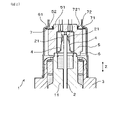
- FIG. 1 is a cross-sectional view taken along the axial direction of the gas sensor in the first embodiment.
- FIG. 2 is an enlarged cross-sectional view of the vicinity of the insulating insulator in the first embodiment.
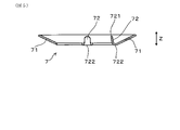
- FIG. 3 is a plan view of the disc spring in the first embodiment.
- FIG. 4 is a cross-sectional view taken along the line IV-IV of FIG.
- FIG. 5 is a cross-sectional view corresponding to a cross section taken along the line IV-IV of FIG. 3 of a disc spring having no flange.
- FIG. 6 is a partial cross-sectional perspective view of the countersunk spring in the first embodiment.
- FIG. 7 is a cross-sectional view of the tip side sub-assy in the first embodiment.
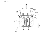
- FIG. 8 is a cross-sectional view of the terminal portion sub-assy in the first embodiment.
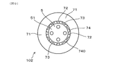
- FIG. 9 is a view taken along the line IX of FIG.
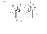
- FIG. 10 is an explanatory view of the method of assembling the gas sensor in the first embodiment, and is a schematic cross-sectional view of a state immediately before elastically compressing the disc spring.
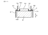
- FIG. 11 is an explanatory view of the method of assembling the gas sensor in the first embodiment, and is a schematic cross-sectional view of a state in which the disc spring is elastically compressed.
- FIG. 10 is an explanatory view of the method of assembling the gas sensor in the first embodiment, and is a schematic cross-sectional view of a state in which the disc spring is elastically compressed.
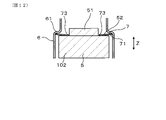
- FIG. 12 is an explanatory view of the method of assembling the gas sensor in the first embodiment, and is another schematic cross-sectional view of the state in which the disc spring is elastically compressed.
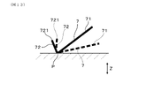
- FIG. 13 is a schematic view showing a state before and after elastic compression of the disc spring in the first embodiment.
- the gas sensor 1 of this embodiment has a sensor element 2, a housing 3, a contact terminal 4, an insulating insulator 5, a base end side cover 6, and a disc spring 7.
- the sensor element 2 is an element that detects a specific gas concentration in the gas to be measured.
- the sensor element 2 is arranged on the inner peripheral side of the housing 3.
- the contact terminal 4 comes into contact with the electrode terminal 21 formed at the base end portion of the sensor element 2.
- the insulating insulator 5 holds the contact terminal 4.
- the base end side cover 6 is fixed to the base end side of the housing 3 and covers the insulating insulator 5.
- the disc spring 7 is arranged between the base end side cover 6 and the insulating insulator 5, and pushes the insulating insulator 5 toward the tip side.
- the insulating insulator 5 has a proximal end side projecting portion 51 projecting toward the proximal end side. Further, the insulating insulator 5 has an outer peripheral base end surface 52 facing the base end side around the base end side protrusion 51.
- the disc spring 7 has an annular main body portion 71 and a plurality of claw portions 72. As shown in FIGS. 2 and 4, the claw portion 72 protrudes from the inner peripheral end of the annular main body portion 71 toward the base end side.
- the protruding end 721 of the claw portion 72 of the disc spring 7 is separated from the base end side protruding portion 51. Further, the protruding end 721 of the claw portion 72 is located on the distal end side in the axial direction Z with respect to the proximal end of the proximal end side protruding portion 51 of the insulating insulator 5.
- the gas sensor 1 can be installed in the exhaust pipe of the internal combustion engine of a vehicle, for example, to detect the gas of the exhaust gas flowing in the exhaust pipe.
- the gas sensor 1 is attached to the exhaust pipe by screwing the mounting screw portion 31 of the housing 3 into the female screw provided in the exhaust pipe.
- the side inserted into the exhaust pipe is referred to as the tip end side, and the opposite side thereof is referred to as the base end side.
- the gas sensor 1 of the present embodiment has an element holder 11 that holds the sensor element 2.
- the element holder 11 is held on the inner peripheral side of the housing 3 while the sensor element 2 is inserted and held.
- the element holder 11 is made of, for example, an insulating member such as ceramic.
- the material of the element holder 11 is not particularly limited, and may be made of metal, for example.
- the tip of the insulating insulator 5 and the base end of the element holder 11 are in contact with each other in the axial direction Z. That is, the insulating insulator 5 is sandwiched between the disc spring 7 and the element holder 11. Then, the elastically deformed disc spring 7 presses the insulating insulator 5 against the element holder 11 in the axial direction Z by the restoring force. As a result, the insulating insulator 5 is stably arranged in the base end side cover 6.
- the base end side cover 6 is fixed to the base end portion of the housing 3 by welding or the like.
- the base end side cover 6 is formed in a cylindrical shape so as to cover the insulating insulator 5.
- the base end side cover 6 has a stepped portion 61 whose inner surface faces the tip end side at an axial position near the base end portion of the insulating insulator 5.
- the outer peripheral end of the disc spring 7 is supported by the step portion 61. Then, a part of the vicinity of the inner peripheral end of the disc spring 7 is in contact with the outer peripheral base end surface 52 of the insulating insulator 5. In this way, the disc spring 7 is interposed between the base end side cover 6 and the insulating insulator 5.
- the insulating insulator 5 is made of, for example, a ceramic such as alumina.
- the insulating insulator 5 houses and holds a plurality of contact terminals 4 inside.
- the contact terminal 4 is in pressure contact with the electrode terminal 21 of the sensor element 2.
- the electrode terminal 21 is electrically connected to a sensor cell (not shown) of the sensor element 2.
- Each contact terminal 4 is connected to the lead wire 12 by penetrating the base end portion thereof to the base end side of the insulating insulator 5. As shown in FIG. 1, the lead wire 12 penetrates the rubber bush 13 provided at the base end portion of the base end side cover 6 and extends to the outside.
- the tip side cover 16 is fixed to the tip end side of the housing 3.
- the tip side cover 16 is formed so as to cover the tip portion of the sensor element 2.
- the front end side cover 16 is formed with a ventilation hole 161 through which the gas to be measured passes.
- the tip side cover 16 has a double structure.
- FIG. 4, and FIG. 6 show the shape of the disc spring 7 in the free state.
- the annular main body 71 is formed in an annular shape.
- the annular main body 71 is inclined toward the proximal end side toward the outer peripheral side.
- a plurality of claw portions 72 project from the inner peripheral end of the annular main body portion 71.
- Each claw portion 72 protrudes from the inner peripheral end of the annular main body portion 71 toward the inner peripheral side and is curved and protrudes toward the base end side.
- the claw portion 72 is inclined toward the inner peripheral side toward the proximal end side.
- the disc spring 7 has a flange portion 73 protruding from the inner peripheral end of the annular main body portion 71 toward the inner peripheral side.
- the flange portion 73 is in contact with the outer peripheral base end surface 52 of the insulating insulator 5 (see FIG. 12).
- the flange portion 73 is formed in a planar shape substantially orthogonal to the axial direction Z in the free state.
- a slit 74 is formed between the claw portion 72 and the flange portion 73 in the circumferential direction of the disc spring 7.
- a plurality of flange portions 73 are formed side by side in the circumferential direction between two claw portions 72 adjacent to each other in the circumferential direction of the disc spring 7.
- two flange portions 73 are formed side by side in the circumferential direction between two adjacent claw portions 72.
- a slit 740 is formed between the two flanges 73. As shown in FIG.
- the root portion 722 and the flange portion 73 of the claw portion 72 branched from the annular main body portion 71 is slightly closer to the tip end side in the axial direction Z (that is, than the inner peripheral end of the annular main body portion 71). , The lower side of FIG. 4).
- the claw portion 72 is formed so as to protrude toward the proximal end side in the axial direction Z after slightly protruding toward the tip end side in the axial direction Z at the root portion 722 branching from the annular main body portion 71. Therefore, if the flange portion 73 is not provided, as shown in FIG.
- the disc spring 7 is made of a material that can secure sufficient spring characteristics even in a high temperature environment in the exhaust system of an internal combustion engine.
- the material of the disc spring 7 for example, alloys such as Inconel 718, Inconel X750, Inconel 600, SUS310, and SUS304 can be used. Inconel is a registered trademark.
- the plate thickness of the disc spring 7 can be, for example, about 0.2 to 1.1 mm.
- the tip side cover 16 and the element holder 11 holding the sensor element 2 are fixed to the housing 3, and the tip side sub-assy 101 is assembled.
- the contact terminal 4 is assembled to the insulating insulator 5, and the disc spring 7 is attached to the insulating insulator 5 to assemble the contact portion sub-assy 102.
- the disc spring 7 shown in FIGS. 3, 4, and 6 is attached to the outer periphery of the base end side projecting portion 51 of the insulating insulator 5, as shown in FIGS. 8 and 9. .. That is, the base end side protruding portion 51 is fitted inside the disc spring 7. At this time, the plurality of claws 72 of the disc spring 7 are in pressure contact with the outer peripheral surface of the base end side protruding portion 51.
- each claw portion 72 is slightly elastically deformed, and the diameter of the inscribed circle of the protruding ends 721 of the plurality of claw portions 72 is slightly wider than in the free state.
- the diameter of the inscribed circle of the protruding ends 721 of the plurality of claws 72 in the disc spring 7 in the free state is slightly smaller than the diameter of the base end side protruding portion 51 of the insulating insulator 5. Therefore, as described above, the plurality of claws 72 are pressed against the base end side protrusion 51, and the disc spring 7 is attached to the insulating insulator 5.
- the claw portion 72 is inclined toward the inner peripheral side toward the proximal end side. Then, the protruding end 721 of the claw portion 72 is in pressure contact with the side surface of the base end side protruding portion 51 of the insulating insulator 5.
- the corner portion of the proximal end of the proximal end side protruding portion 51 has a chamfered portion 511. Therefore, the protruding end 721 of the claw portion 72 is in contact with the side surface of the base end side protruding portion 51 on the tip end side in the axial direction Z with respect to the chamfered portion 511.
- the disc spring 7 is also brought into contact with the outer peripheral base end surface 52 of the insulating insulator 5. At this time, the flange portion 73 also comes into contact with the outer peripheral base end surface 52 together with the root portion of the claw portion 72. At the stage of assembling the contact portion sub-assy 102, the disc spring 7 does not necessarily have to be in contact with the outer peripheral base end surface 52. That is, the contact of the disc spring 7 with the outer peripheral base end surface 52 can be realized when the disc spring 7 is subsequently elastically compressed.
- the contact portion sub-assy 102 shown in FIGS. 8 and 9 is assembled. It is also possible to connect the lead wire 12 to the contact terminal 4 at the stage of the contact portion sub-assy 102. Further, as shown in FIGS. 9 and 12, the flange portion 73 does not come into contact with the base end side protruding portion 51 before or after elastic compression of the disc spring 7.
- the contact portion sub-assy 102 is arranged on the base end side of the tip-side sub-assy 101.
- the tip of the insulating insulator 5 comes into contact with the base end of the element holder 11.
- the base end side cover 6 is covered from the base end side so that the base end side cover 6 covers the outer periphery of the contact portion sub-assy 102.
- the step portion 61 of the base end side cover 6 abuts on the disc spring 7 in the contact portion sub-assy 102 from the base end side in the axial direction Z.
- the step portion 61 abuts on the outer peripheral end of the annular main body portion 71 of the disc spring 7.
- the step portion 61 abuts over the entire circumference of the outer peripheral edge of the annular main body portion 71.
- the angle of the claw portion 72 changes as well as the angle of the annular main body 71.
- the shape shown by the solid line shows the state before the elastic deformation
- the shape shown by the broken line shows the state after the elastic deformation.
- the vicinity of the inner peripheral end of the annular main body 71 and the vicinity of the root of the claw portion 72 becomes the fulcrum P, and the outer peripheral end of the annular main body 71 is deformed toward the tip side.
- the protruding end 721 of the claw portion 72 moves toward the outer peripheral side, or the pressure contact force of the claw portion 72 with the base end side protruding portion 51 decreases.
- the protruding end 721 of the claw portion 72 remains until the deformed portion is restored. , Remains in contact with the proximal end side protrusion 51. After the above deformation is restored, the protruding end 721 of the claw portion 72 is displaced toward the outer peripheral side due to the deformation of the annular main body portion 71. As a result, as shown in FIG. 11, the protruding end 721 of the claw portion 72 is separated from the base end side protruding portion 51. Therefore, the compressive deformation of the disc spring 7 is not hindered by the presence of the claw portion 72. As a result, the restoring force corresponding to the elastic compression amount of the disc spring 7 acts on the insulating insulator 5, and it becomes easy to adjust the load as intended.
- the base end side cover 6 With the base end side cover 6 pushed in to a predetermined position, the base end side cover 6 is fixed to the housing 3 by welding or the like. As a result, the gas sensor 1 shown in FIG. 1 is obtained.
- the disc spring 7 has a plurality of claws 72. Therefore, in the stage before assembling the gas sensor 1, the disc spring 7 can be attached to the insulating insulator 5 by pressing the plurality of claws 72 against the side surface of the base end side protruding portion 51 of the insulating insulator 5.
- the disc spring 7 can be attached to the insulating insulator 5 before assembling the gas sensor 1, the ease of assembling the gas sensor 1 can be improved. Since the elastic deformation of the disc spring 7 is not hindered, the load of the insulating insulator 5 can be easily adjusted by the disc spring 7.
- the disc spring 7 has a flange portion 73, and the flange portion 73 is in contact with the outer peripheral base end surface 52. Therefore, the contact area where the disc spring 7 abuts on the outer peripheral base end surface 52 of the insulating insulator 5 can be increased. That is, since the contact portion of the disc spring 7 with respect to the outer peripheral base end surface 52 can be provided not only at the root portion of the claw portion 72 but also at the flange portion 73, it is easy to increase the contact area. As a result, it is possible to prevent the load from acting locally on the insulating insulator 5.
- a slit 74 is formed between the claw portion 72 and the flange portion 73 in the circumferential direction of the disc spring 7.
- a plurality of flange portions 73 are formed side by side in the circumferential direction between two claw portions 72 adjacent to each other in the circumferential direction of the disc spring 7. As a result, it is easy to increase the contact area between the outer peripheral base end surface 52 of the insulating insulator 5 and the disc spring 7 while suppressing the spring constant of the disc spring 7 from becoming too high due to the provision of the flange portion 73.
- the protruding end 721 of the claw portion 72 is separated from the base end side protruding portion 51. Therefore, it is possible to more reliably prevent the interference between the claw portion 72 and the base end side projecting portion 51 of the insulating insulator 5 from hindering the elastic deformation of the disc spring 7.
- the insulating insulator 5 is in contact with the element holder 11, but the insulating insulator 5 may be in contact with another member such as the housing 3. Further, in the above embodiment, the element holder 11 holding the sensor element 2 is fixed to the housing 3, but the sensor element may be directly held by the housing. Further, in the above embodiment, the number of claws 72 in the disc spring 7 is set to 4, but the number of claws may be a plurality and is not limited. However, from the viewpoint of stability, the number of claws is preferably 3 or more.
Abstract
A gas sensor (1) has: a sensor element (2) for detecting the concentration of a specific gas in a gas to be measured; a housing (3), on an inner peripheral side of which the sensor element (2) is disposed; a contact element (4) which contacts an electrode terminal (21) formed in the sensor element (2); an insulator (5) which retains the contact element (4); a proximal-end-side cover (6) which is fixed to a proximal-end side of the housing (3) and covers the insulator (5); and a disc spring (7) which is disposed between the proximal-end-side cover (6) and the insulator (5) and presses the insulator (5) toward a distal-end side. The insulator (5) has a proximal-end-side protruding part (51) that protrudes toward the proximal end, and has an outer circumferential proximal-end surface (52) that faces the proximal-end side on the periphery of the proximal-end-side protruding part (51). The disc spring (7) has an annular main body section (71) and a plurality of claw sections (72) that protrude toward the proximal end from an inner circumferential end of the annular main body section (71).
Description
本出願は、2020年10月22日に出願された日本出願番号2020-177372号に基づくもので、ここにその記載内容を援用する。
This application is based on Japanese Application No. 2020-177372 filed on October 22, 2020, and the contents of the description are incorporated herein by reference.
本開示は、ガスセンサに関する。
This disclosure relates to gas sensors.
内燃機関の排気系等に配設されて、排ガス等、被測定ガス中の特定ガス濃度を検出するガスセンサが、種々開発されている。かかるガスセンサにおいて、センサ素子の電極端子と接触する接点端子を保持する絶縁碍子を備えたものがある。この絶縁碍子を安定保持するために、弾性部材によって絶縁碍子を軸方向に押す構造が、特許文献1に開示されている。
Various gas sensors have been developed that are arranged in the exhaust system of an internal combustion engine and detect the concentration of a specific gas in the gas to be measured such as exhaust gas. Some such gas sensors are provided with an insulator that holds a contact terminal that comes into contact with the electrode terminal of the sensor element. Patent Document 1 discloses a structure in which an insulator is pushed in the axial direction by an elastic member in order to stably hold the insulator.
ガスセンサを組み立てる際、弾性部材が所定の位置からずれて組付けられてしまうと、製品不良を招くおそれがある。特許文献1には、弾性部材を絶縁碍子に固定できる態様も記載されている。この記載によると、略環状の弾性部材の内周面を、絶縁碍子の一部の外周面に圧接させた状態で、弾性部材を絶縁碍子に固定することとなる。
When assembling the gas sensor, if the elastic member is assembled out of the specified position, it may lead to product failure. Patent Document 1 also describes an embodiment in which an elastic member can be fixed to an insulating insulator. According to this description, the elastic member is fixed to the insulating insulator in a state where the inner peripheral surface of the substantially annular elastic member is pressed against the outer peripheral surface of a part of the insulating insulator.
特許文献1に開示された弾性部材は、中空状であり、周方向に直交する断面の形状が略C字形状を有する。
それゆえ、弾性部材をプラグ軸方向に圧縮すると、弾性部材が径方向の内周側及び外周側に広がるように変形しようとする。つまり、弾性部材が固定された絶縁碍子を、ガスセンサの他の構成部品に組付ける際、弾性部材が径方向の内周側及び外周側に広がるように変形しようとする。しかし、弾性部材の内周側は絶縁碍子に接触しているため、弾性部材の変形が妨げられる。それゆえ、軸方向における弾性部材から絶縁碍子への荷重を狙い通りに印加することが困難となる。 The elastic member disclosed inPatent Document 1 is hollow and has a substantially C-shaped cross section orthogonal to the circumferential direction.
Therefore, when the elastic member is compressed in the plug axial direction, the elastic member tends to be deformed so as to spread toward the inner peripheral side and the outer peripheral side in the radial direction. That is, when the insulating insulator to which the elastic member is fixed is assembled to other components of the gas sensor, the elastic member tries to be deformed so as to spread toward the inner peripheral side and the outer peripheral side in the radial direction. However, since the inner peripheral side of the elastic member is in contact with the insulating insulator, the deformation of the elastic member is hindered. Therefore, it becomes difficult to apply the load from the elastic member in the axial direction to the insulating insulator as intended.
それゆえ、弾性部材をプラグ軸方向に圧縮すると、弾性部材が径方向の内周側及び外周側に広がるように変形しようとする。つまり、弾性部材が固定された絶縁碍子を、ガスセンサの他の構成部品に組付ける際、弾性部材が径方向の内周側及び外周側に広がるように変形しようとする。しかし、弾性部材の内周側は絶縁碍子に接触しているため、弾性部材の変形が妨げられる。それゆえ、軸方向における弾性部材から絶縁碍子への荷重を狙い通りに印加することが困難となる。 The elastic member disclosed in
Therefore, when the elastic member is compressed in the plug axial direction, the elastic member tends to be deformed so as to spread toward the inner peripheral side and the outer peripheral side in the radial direction. That is, when the insulating insulator to which the elastic member is fixed is assembled to other components of the gas sensor, the elastic member tries to be deformed so as to spread toward the inner peripheral side and the outer peripheral side in the radial direction. However, since the inner peripheral side of the elastic member is in contact with the insulating insulator, the deformation of the elastic member is hindered. Therefore, it becomes difficult to apply the load from the elastic member in the axial direction to the insulating insulator as intended.
このように、特許文献1に開示された構成では、組付け後における絶縁碍子への荷重を調整しやすくしつつ、組付け前には絶縁碍子に弾性部材を固定しておくことは、困難である。つまり、上記構成では、絶縁碍子への荷重調整の容易性と、ガスセンサの組立容易性との両立を図ることは、困難である。
As described above, in the configuration disclosed in Patent Document 1, it is difficult to fix the elastic member to the insulating insulator before assembling while making it easy to adjust the load on the insulating insulator after assembling. be. That is, in the above configuration, it is difficult to achieve both the ease of adjusting the load on the insulating insulator and the ease of assembling the gas sensor.
本開示は、絶縁碍子への荷重調整の容易性と、ガスセンサの組立容易性との両立を図ることができるガスセンサを提供しようとするものである。
The present disclosure is intended to provide a gas sensor capable of achieving both the ease of adjusting the load on the insulating insulator and the ease of assembling the gas sensor.
本開示の一態様は、被測定ガス中の特定ガス濃度を検出するセンサ素子と、
該センサ素子が内周側に配されるハウジングと、
上記センサ素子に形成された電極端子に接触する接点端子と、
該接点端子を保持する絶縁碍子と、
上記ハウジングの基端側に固定されると共に上記絶縁碍子を覆う基端側カバーと、
該基端側カバーと絶縁碍子との間に配され、該絶縁碍子を先端側へ押す皿ばねと、を有し、
上記絶縁碍子は、基端側に突出した基端側突出部を有すると共に、該基端側突出部の周囲において基端側を向いた外周基端面を有し、
上記皿ばねは、環状本体部と、該環状本体部の内周端から基端側へ突出した複数の爪部とを有する、ガスセンサにある。 One aspect of the present disclosure is a sensor element that detects a specific gas concentration in the gas to be measured, and
A housing in which the sensor element is arranged on the inner peripheral side, and
Contact terminals that come into contact with the electrode terminals formed on the sensor element,
Insulators that hold the contact terminals and
A base end cover that is fixed to the base end side of the housing and covers the insulating insulator,
It has a disc spring, which is arranged between the base end side cover and the insulating insulator and pushes the insulating insulator toward the tip side.
The insulating insulator has a base end side protrusion protruding toward the base end side, and also has an outer peripheral base end surface facing the base end side around the base end side protrusion.
The disc spring is in a gas sensor having an annular main body portion and a plurality of claw portions protruding from the inner peripheral end of the annular main body portion toward the proximal end side.
上記ガスセンサにおいて、上記皿ばねは、複数の上記爪部を有する。そのため、ガスセンサを組み立てる前の段階において、複数の爪部を絶縁碍子の基端側突出部の側面に圧接させて、皿ばねを絶縁碍子に取り付けておくことができる。
In the gas sensor, the disc spring has a plurality of the claws. Therefore, in the stage before assembling the gas sensor, a plurality of claws can be pressed against the side surface of the base end side protruding portion of the insulating insulator, and the disc spring can be attached to the insulating insulator.
その後、ガスセンサを組み立てる際に、皿ばねの環状本体部を軸方向に弾性圧縮したとき、環状本体部の変形に伴い、基端側突出部に対する爪部の圧力が低下する。したがって、絶縁碍子と爪部との干渉によって環状本体部の弾性変形が妨げられることはない。それゆえ、皿ばねによる絶縁碍子への荷重調整を容易に行うことができる。
After that, when the annular body of the disc spring is elastically compressed in the axial direction when assembling the gas sensor, the pressure of the claw on the protrusion on the proximal end side decreases due to the deformation of the annular body. Therefore, the elastic deformation of the annular main body portion is not hindered by the interference between the insulating insulator and the claw portion. Therefore, it is possible to easily adjust the load on the insulating insulator by the disc spring.
上述のように、ガスセンサの組み立て前に皿ばねを絶縁碍子に取り付けておくことができるため、ガスセンサの組立容易性を向上させることができる。そして、皿ばねの弾性変形が妨げられることがないため、皿ばねによる絶縁碍子への荷重調整を容易に行うことができる。
As described above, since the disc spring can be attached to the insulating insulator before assembling the gas sensor, the ease of assembling the gas sensor can be improved. Since the elastic deformation of the disc spring is not hindered, the load can be easily adjusted to the insulating insulator by the disc spring.
以上のごとく、上記態様によれば、絶縁碍子への荷重調整の容易性と、ガスセンサの組立容易性との両立を図ることができるガスセンサを提供することができる。
As described above, according to the above aspect, it is possible to provide a gas sensor capable of achieving both the ease of load adjustment on the insulating insulator and the ease of assembling the gas sensor.
本開示についての上記目的およびその他の目的、特徴や利点は、添付の図面を参照しながら下記の詳細な記述により、より明確になる。その図面は、
図1は、実施形態1における、ガスセンサの軸方向に沿った断面図であり、
図2は、実施形態1における、絶縁碍子付近の拡大断面図であり、
図3は、実施形態1における、皿ばねの平面図であり、
図4は、図3のIV-IV線矢視断面図であり、
図5は、鍔部を設けていない皿ばねの、図3のIV-IV線矢視断面相当図であり、
図6は、実施形態1における、皿ばねの一部断面斜視図であり、
図7は、実施形態1における、先端側サブアッシーの断面図であり、
図8は、実施形態1における、端子部サブアッシーの断面図であり、
図9は、図8のIX矢視図であり、
図10は、実施形態1における、ガスセンサの組み立て方法の説明図であって、皿ばねを弾性圧縮する直前の状態の断面模式図であり、
図11は、実施形態1における、ガスセンサの組み立て方法の説明図であって、皿ばねを弾性圧縮した状態の断面模式図であり、
図12は、実施形態1における、ガスセンサの組み立て方法の説明図であって、皿ばねを弾性圧縮した状態の他の断面模式図であり、
図13は、実施形態1における、皿ばねの弾性圧縮前後の状態を示す模式図である。
The above objectives and other objectives, features and advantages of the present disclosure will be further clarified by the following detailed description with reference to the accompanying drawings. The drawing is
FIG. 1 is a cross-sectional view taken along the axial direction of the gas sensor in the first embodiment. FIG. 2 is an enlarged cross-sectional view of the vicinity of the insulating insulator in the first embodiment. FIG. 3 is a plan view of the disc spring in the first embodiment. FIG. 4 is a cross-sectional view taken along the line IV-IV of FIG. FIG. 5 is a cross-sectional view corresponding to a cross section taken along the line IV-IV of FIG. 3 of a disc spring having no flange. FIG. 6 is a partial cross-sectional perspective view of the countersunk spring in the first embodiment. FIG. 7 is a cross-sectional view of the tip side sub-assy in the first embodiment. FIG. 8 is a cross-sectional view of the terminal portion sub-assy in the first embodiment. FIG. 9 is a view taken along the line IX of FIG. FIG. 10 is an explanatory view of the method of assembling the gas sensor in the first embodiment, and is a schematic cross-sectional view of a state immediately before elastically compressing the disc spring. FIG. 11 is an explanatory view of the method of assembling the gas sensor in the first embodiment, and is a schematic cross-sectional view of a state in which the disc spring is elastically compressed. FIG. 12 is an explanatory view of the method of assembling the gas sensor in the first embodiment, and is another schematic cross-sectional view of the state in which the disc spring is elastically compressed. FIG. 13 is a schematic view showing a state before and after elastic compression of the disc spring in the first embodiment.
(実施形態1)
ガスセンサに係る実施形態について、図1~図13を参照して説明する。
本形態のガスセンサ1は、図1に示すごとく、センサ素子2と、ハウジング3と、接点端子4と、絶縁碍子5と、基端側カバー6と、皿ばね7と、を有する。 (Embodiment 1)
An embodiment related to the gas sensor will be described with reference to FIGS. 1 to 13.
As shown in FIG. 1, thegas sensor 1 of this embodiment has a sensor element 2, a housing 3, a contact terminal 4, an insulating insulator 5, a base end side cover 6, and a disc spring 7.
ガスセンサに係る実施形態について、図1~図13を参照して説明する。
本形態のガスセンサ1は、図1に示すごとく、センサ素子2と、ハウジング3と、接点端子4と、絶縁碍子5と、基端側カバー6と、皿ばね7と、を有する。 (Embodiment 1)
An embodiment related to the gas sensor will be described with reference to FIGS. 1 to 13.
As shown in FIG. 1, the
センサ素子2は、被測定ガス中の特定ガス濃度を検出する素子である。ハウジング3の内周側に、センサ素子2が配される。接点端子4は、センサ素子2の基端部に形成された電極端子21に接触する。絶縁碍子5は、接点端子4を保持する。基端側カバー6は、ハウジング3の基端側に固定されると共に絶縁碍子5を覆う。皿ばね7は、基端側カバー6と絶縁碍子5との間に配され、絶縁碍子5を先端側へ押す。
The sensor element 2 is an element that detects a specific gas concentration in the gas to be measured. The sensor element 2 is arranged on the inner peripheral side of the housing 3. The contact terminal 4 comes into contact with the electrode terminal 21 formed at the base end portion of the sensor element 2. The insulating insulator 5 holds the contact terminal 4. The base end side cover 6 is fixed to the base end side of the housing 3 and covers the insulating insulator 5. The disc spring 7 is arranged between the base end side cover 6 and the insulating insulator 5, and pushes the insulating insulator 5 toward the tip side.
図2に示すごとく、絶縁碍子5は、基端側に突出した基端側突出部51を有する。また、絶縁碍子5は、基端側突出部51の周囲において基端側を向いた外周基端面52を有する。
As shown in FIG. 2, the insulating insulator 5 has a proximal end side projecting portion 51 projecting toward the proximal end side. Further, the insulating insulator 5 has an outer peripheral base end surface 52 facing the base end side around the base end side protrusion 51.
皿ばね7は、図3、図4、図6に示すごとく、環状本体部71と、複数の爪部72とを有する。爪部72は、図2、図4に示すごとく、環状本体部71の内周端から基端側へ突出している。
As shown in FIGS. 3, 4, and 6, the disc spring 7 has an annular main body portion 71 and a plurality of claw portions 72. As shown in FIGS. 2 and 4, the claw portion 72 protrudes from the inner peripheral end of the annular main body portion 71 toward the base end side.
図2に示すごとく、ガスセンサ1が組み立てられた状態において、皿ばね7の爪部72の突出端721は、基端側突出部51から離れている。また、爪部72の突出端721は、絶縁碍子5の基端側突出部51の基端よりも、軸方向Zの先端側に位置している。
As shown in FIG. 2, in the state where the gas sensor 1 is assembled, the protruding end 721 of the claw portion 72 of the disc spring 7 is separated from the base end side protruding portion 51. Further, the protruding end 721 of the claw portion 72 is located on the distal end side in the axial direction Z with respect to the proximal end of the proximal end side protruding portion 51 of the insulating insulator 5.
ガスセンサ1は、例えば、車両の内燃機関の排気管に設置されて、排気管内を流れる排ガスのガス検出を行うものとすることができる。ガスセンサ1は、ハウジング3の取付ネジ部31を、排気管に設けた雌ネジに螺合して、排気管に取り付けられる。軸方向Zにおいて、排気管に挿入される側を、先端側、その反対側を、基端側というものとする。
The gas sensor 1 can be installed in the exhaust pipe of the internal combustion engine of a vehicle, for example, to detect the gas of the exhaust gas flowing in the exhaust pipe. The gas sensor 1 is attached to the exhaust pipe by screwing the mounting screw portion 31 of the housing 3 into the female screw provided in the exhaust pipe. In the axial direction Z, the side inserted into the exhaust pipe is referred to as the tip end side, and the opposite side thereof is referred to as the base end side.
本形態のガスセンサ1は、図1、図2に示すごとく、センサ素子2を保持する素子保持体11を有する。素子保持体11は、センサ素子2を挿通させて保持すると共に、ハウジング3の内周側に保持されている。素子保持体11は、例えば、セラミック等の絶縁部材からなる。ただし、素子保持体11の材質は、特に限定されるものではなく、例えば金属製のものとすることもできる。
As shown in FIGS. 1 and 2, the gas sensor 1 of the present embodiment has an element holder 11 that holds the sensor element 2. The element holder 11 is held on the inner peripheral side of the housing 3 while the sensor element 2 is inserted and held. The element holder 11 is made of, for example, an insulating member such as ceramic. However, the material of the element holder 11 is not particularly limited, and may be made of metal, for example.
絶縁碍子5の先端部と素子保持体11の基端部とは、互いに軸方向Zに当接している。すなわち、絶縁碍子5は、皿ばね7と素子保持体11との間に、挟持されている。そして、弾性変形した皿ばね7が、その復元力によって、絶縁碍子5を素子保持体11に軸方向Zに押し付けている。これにより、基端側カバー6内において、絶縁碍子5が安定して配設されている。
The tip of the insulating insulator 5 and the base end of the element holder 11 are in contact with each other in the axial direction Z. That is, the insulating insulator 5 is sandwiched between the disc spring 7 and the element holder 11. Then, the elastically deformed disc spring 7 presses the insulating insulator 5 against the element holder 11 in the axial direction Z by the restoring force. As a result, the insulating insulator 5 is stably arranged in the base end side cover 6.
基端側カバー6は、ハウジング3の基端部に溶接等にて固定されている。基端側カバー6は、絶縁碍子5を覆うように筒状に形成されている。基端側カバー6は、絶縁碍子5の基端部付近の軸方向位置に、内面が先端側を向いた段部61を有する。この段部61に、皿ばね7の外周端が支承されている。そして、皿ばね7の内周端付近の一部が、絶縁碍子5の外周基端面52に当接している。このようにして、皿ばね7が、基端側カバー6と絶縁碍子5との間に介在している。
The base end side cover 6 is fixed to the base end portion of the housing 3 by welding or the like. The base end side cover 6 is formed in a cylindrical shape so as to cover the insulating insulator 5. The base end side cover 6 has a stepped portion 61 whose inner surface faces the tip end side at an axial position near the base end portion of the insulating insulator 5. The outer peripheral end of the disc spring 7 is supported by the step portion 61. Then, a part of the vicinity of the inner peripheral end of the disc spring 7 is in contact with the outer peripheral base end surface 52 of the insulating insulator 5. In this way, the disc spring 7 is interposed between the base end side cover 6 and the insulating insulator 5.
絶縁碍子5は、例えば、アルミナ等のセラミック等からなる。絶縁碍子5は、内側に、複数の接点端子4を収容して保持している。接点端子4は、センサ素子2の電極端子21に圧接している。電極端子21は、センサ素子2のセンサセル(図示略)に電気的に接続されている。また、センサ素子2がヒータを一体化している場合は、ヒータに電気的に接続された電極端子21に圧接する接点端子4も存在する。各接点端子4は、その基端部を絶縁碍子5の基端側に貫通させて、リード線12に接続している。図1に示すごとく、リード線12は、基端側カバー6の基端部に設けられたゴムブッシュ13を貫通して、外部に延設されている。
The insulating insulator 5 is made of, for example, a ceramic such as alumina. The insulating insulator 5 houses and holds a plurality of contact terminals 4 inside. The contact terminal 4 is in pressure contact with the electrode terminal 21 of the sensor element 2. The electrode terminal 21 is electrically connected to a sensor cell (not shown) of the sensor element 2. Further, when the sensor element 2 integrates the heater, there is also a contact terminal 4 that is in pressure contact with the electrode terminal 21 electrically connected to the heater. Each contact terminal 4 is connected to the lead wire 12 by penetrating the base end portion thereof to the base end side of the insulating insulator 5. As shown in FIG. 1, the lead wire 12 penetrates the rubber bush 13 provided at the base end portion of the base end side cover 6 and extends to the outside.
図1に示すごとく、ハウジング3の先端側には、先端側カバー16が固定されている。先端側カバー16は、センサ素子2の先端部を覆うように形成されている。先端側カバー16には、被測定ガスが通過する通気孔161が形成されている。本形態においては、先端側カバー16は、二重構造となっている。
As shown in FIG. 1, the tip side cover 16 is fixed to the tip end side of the housing 3. The tip side cover 16 is formed so as to cover the tip portion of the sensor element 2. The front end side cover 16 is formed with a ventilation hole 161 through which the gas to be measured passes. In this embodiment, the tip side cover 16 has a double structure.
図3、図4、図6に、自由状態にある皿ばね7の形状を示す。
環状本体部71は、図3に示すごとく、円環状に形成されている。そして、図4に示すごとく、自由状態においては、環状本体部71は、外周側へ向かうにつれて基端側へ向かうように傾斜している。図3、図4、図6に示すごとく、環状本体部71の内周端から、複数の爪部72が突出している。各爪部72は、環状本体部71の内周端から、内周側に突出すると共に湾曲して基端側へ突出している。自由状態において、爪部72は、基端側へ向かうほど内周側に向かうように傾斜している。 3, FIG. 4, and FIG. 6 show the shape of thedisc spring 7 in the free state.
As shown in FIG. 3, the annularmain body 71 is formed in an annular shape. Then, as shown in FIG. 4, in the free state, the annular main body 71 is inclined toward the proximal end side toward the outer peripheral side. As shown in FIGS. 3, 4, and 6, a plurality of claw portions 72 project from the inner peripheral end of the annular main body portion 71. Each claw portion 72 protrudes from the inner peripheral end of the annular main body portion 71 toward the inner peripheral side and is curved and protrudes toward the base end side. In the free state, the claw portion 72 is inclined toward the inner peripheral side toward the proximal end side.
環状本体部71は、図3に示すごとく、円環状に形成されている。そして、図4に示すごとく、自由状態においては、環状本体部71は、外周側へ向かうにつれて基端側へ向かうように傾斜している。図3、図4、図6に示すごとく、環状本体部71の内周端から、複数の爪部72が突出している。各爪部72は、環状本体部71の内周端から、内周側に突出すると共に湾曲して基端側へ突出している。自由状態において、爪部72は、基端側へ向かうほど内周側に向かうように傾斜している。 3, FIG. 4, and FIG. 6 show the shape of the
As shown in FIG. 3, the annular
また、皿ばね7は、図3、図6に示すごとく、環状本体部71の内周端から内周側へ突出した鍔部73を有する。ガスセンサ1において、鍔部73は、絶縁碍子5の外周基端面52に接触している(図12参照)。鍔部73は、自由状態において、軸方向Zに対して略直交する平面状に形成されている。
Further, as shown in FIGS. 3 and 6, the disc spring 7 has a flange portion 73 protruding from the inner peripheral end of the annular main body portion 71 toward the inner peripheral side. In the gas sensor 1, the flange portion 73 is in contact with the outer peripheral base end surface 52 of the insulating insulator 5 (see FIG. 12). The flange portion 73 is formed in a planar shape substantially orthogonal to the axial direction Z in the free state.
図3、図6に示すごとく、皿ばね7の周方向における爪部72と鍔部73との間には、スリット74が形成されている。皿ばね7の周方向において隣り合う2つの爪部72の間に、複数の鍔部73が周方向に並んで形成されている。本形態においては、隣り合う2つの爪部72の間に、2つの鍔部73が周方向に並んで形成されている。2つの鍔部73の間には、スリット740が形成されている。図4に示すごとく、環状本体部71から分岐した爪部72の根元部722及び鍔部73の少なくとも一部は、環状本体部71の内周端よりも若干、軸方向Zの先端側(すなわち、図4の下側)に配されている。爪部72は、環状本体部71から分岐する根元部722において、周囲よりもわずかに軸方向Zの先端側へ突き出た後に、軸方向Zの基端側へ跳ね上がるように形成されている。それゆえ、仮に、鍔部73を設けていないと、図5に示すごとく、爪部72の根元部722だけが軸方向Zの先端側へ突出した状態となり、当該部分のみが絶縁碍子5の外周基端面52に当接することとなる。そこで、鍔部73を設けることで、皿ばね7は、爪部72の根元部722のみならず、鍔部73の一部においても、絶縁碍子5に当接することとなる。つまり、皿ばね7と絶縁碍子5との当接面積を大きくすることができる。
As shown in FIGS. 3 and 6, a slit 74 is formed between the claw portion 72 and the flange portion 73 in the circumferential direction of the disc spring 7. A plurality of flange portions 73 are formed side by side in the circumferential direction between two claw portions 72 adjacent to each other in the circumferential direction of the disc spring 7. In this embodiment, two flange portions 73 are formed side by side in the circumferential direction between two adjacent claw portions 72. A slit 740 is formed between the two flanges 73. As shown in FIG. 4, at least a part of the root portion 722 and the flange portion 73 of the claw portion 72 branched from the annular main body portion 71 is slightly closer to the tip end side in the axial direction Z (that is, than the inner peripheral end of the annular main body portion 71). , The lower side of FIG. 4). The claw portion 72 is formed so as to protrude toward the proximal end side in the axial direction Z after slightly protruding toward the tip end side in the axial direction Z at the root portion 722 branching from the annular main body portion 71. Therefore, if the flange portion 73 is not provided, as shown in FIG. 5, only the root portion 722 of the claw portion 72 protrudes toward the tip end side in the axial direction Z, and only this portion is the outer periphery of the insulating insulator 5. It will come into contact with the base end surface 52. Therefore, by providing the flange portion 73, the disc spring 7 comes into contact with the insulating insulator 5 not only at the root portion 722 of the claw portion 72 but also at a part of the flange portion 73. That is, the contact area between the disc spring 7 and the insulating insulator 5 can be increased.
皿ばね7は、内燃機関の排気系における高温環境下においても充分なばね特性を確保できる材料からなる。皿ばね7の材料としては、例えば、インコネル718、インコネルX750、インコネル600、SUS310、SUS304等の合金を用いることができる。なお、インコネルは登録商標である。また、皿ばね7の板厚は、例えば、0.2~1.1mm程度とすることができる。
The disc spring 7 is made of a material that can secure sufficient spring characteristics even in a high temperature environment in the exhaust system of an internal combustion engine. As the material of the disc spring 7, for example, alloys such as Inconel 718, Inconel X750, Inconel 600, SUS310, and SUS304 can be used. Inconel is a registered trademark. Further, the plate thickness of the disc spring 7 can be, for example, about 0.2 to 1.1 mm.
次に、本形態のガスセンサ1の組み立て方法の一例につき、説明する。
まず、図7に示すごとく、ハウジング3に、先端側カバー16、及び、センサ素子2を保持した素子保持体11を固定して、先端側サブアッシー101を組み立てる。一方、図8に示すごとく、絶縁碍子5に接点端子4を組み付けると共に、皿ばね7を絶縁碍子5に取り付けて、接点部サブアッシー102を組み立てる。 Next, an example of the method of assembling thegas sensor 1 of the present embodiment will be described.
First, as shown in FIG. 7, thetip side cover 16 and the element holder 11 holding the sensor element 2 are fixed to the housing 3, and the tip side sub-assy 101 is assembled. On the other hand, as shown in FIG. 8, the contact terminal 4 is assembled to the insulating insulator 5, and the disc spring 7 is attached to the insulating insulator 5 to assemble the contact portion sub-assy 102.
まず、図7に示すごとく、ハウジング3に、先端側カバー16、及び、センサ素子2を保持した素子保持体11を固定して、先端側サブアッシー101を組み立てる。一方、図8に示すごとく、絶縁碍子5に接点端子4を組み付けると共に、皿ばね7を絶縁碍子5に取り付けて、接点部サブアッシー102を組み立てる。 Next, an example of the method of assembling the
First, as shown in FIG. 7, the
接点部サブアッシー102を組み立てるにあたっては、図3、図4、図6に示した皿ばね7を、図8、図9に示すように、絶縁碍子5の基端側突出部51の外周に取り付ける。すなわち、皿ばね7の内側に、基端側突出部51を嵌入させる。このとき、皿ばね7の複数の爪部72が、基端側突出部51の外周面に圧接する。
In assembling the contact portion sub-assy 102, the disc spring 7 shown in FIGS. 3, 4, and 6 is attached to the outer periphery of the base end side projecting portion 51 of the insulating insulator 5, as shown in FIGS. 8 and 9. .. That is, the base end side protruding portion 51 is fitted inside the disc spring 7. At this time, the plurality of claws 72 of the disc spring 7 are in pressure contact with the outer peripheral surface of the base end side protruding portion 51.
この状態において、各爪部72は若干弾性変形して、複数の爪部72の突出端721の内接円の直径が、自由状態よりも若干広がる。逆に言うと、自由状態にある皿ばね7における複数の爪部72の突出端721の内接円の直径は、絶縁碍子5の基端側突出部51の直径よりも若干小さい。それゆえ、上記のように、複数の爪部72が基端側突出部51に圧接して、皿ばね7が、絶縁碍子5に取り付けられる。
In this state, each claw portion 72 is slightly elastically deformed, and the diameter of the inscribed circle of the protruding ends 721 of the plurality of claw portions 72 is slightly wider than in the free state. Conversely, the diameter of the inscribed circle of the protruding ends 721 of the plurality of claws 72 in the disc spring 7 in the free state is slightly smaller than the diameter of the base end side protruding portion 51 of the insulating insulator 5. Therefore, as described above, the plurality of claws 72 are pressed against the base end side protrusion 51, and the disc spring 7 is attached to the insulating insulator 5.
また、この段階において、図8に示すごとく、爪部72は、基端側へ向かうほど内周側に向かうように傾斜している。そして、爪部72の突出端721が絶縁碍子5の基端側突出部51の側面に圧接している。なお、本形態において、基端側突出部51の基端の角部は、面取り部511を有する。それゆえ、面取り部511よりも軸方向Zの先端側における基端側突出部51の側面に、爪部72の突出端721が接触するようにしてある。
Further, at this stage, as shown in FIG. 8, the claw portion 72 is inclined toward the inner peripheral side toward the proximal end side. Then, the protruding end 721 of the claw portion 72 is in pressure contact with the side surface of the base end side protruding portion 51 of the insulating insulator 5. In this embodiment, the corner portion of the proximal end of the proximal end side protruding portion 51 has a chamfered portion 511. Therefore, the protruding end 721 of the claw portion 72 is in contact with the side surface of the base end side protruding portion 51 on the tip end side in the axial direction Z with respect to the chamfered portion 511.
また、皿ばね7は、絶縁碍子5の外周基端面52にも当接させる。このとき、爪部72の根元部と共に、鍔部73も、外周基端面52に当接する。なお、接点部サブアッシー102の組み立ての段階では、必ずしも、皿ばね7は外周基端面52に当接していなくてもよい。つまり、皿ばね7の外周基端面52への当接は、この後、皿ばね7を弾性圧縮させる際に実現されるようにすることもできる。
The disc spring 7 is also brought into contact with the outer peripheral base end surface 52 of the insulating insulator 5. At this time, the flange portion 73 also comes into contact with the outer peripheral base end surface 52 together with the root portion of the claw portion 72. At the stage of assembling the contact portion sub-assy 102, the disc spring 7 does not necessarily have to be in contact with the outer peripheral base end surface 52. That is, the contact of the disc spring 7 with the outer peripheral base end surface 52 can be realized when the disc spring 7 is subsequently elastically compressed.
このようにして、図8、図9に示す接点部サブアッシー102を組み立てる。なお、この接点部サブアッシー102の段階で、接点端子4にリード線12を接続しておくこともできる。また、鍔部73は、図9、図12に示すごとく、皿ばね7の弾性圧縮前後のいずれにおいても、基端側突出部51には接触しない。
In this way, the contact portion sub-assy 102 shown in FIGS. 8 and 9 is assembled. It is also possible to connect the lead wire 12 to the contact terminal 4 at the stage of the contact portion sub-assy 102. Further, as shown in FIGS. 9 and 12, the flange portion 73 does not come into contact with the base end side protruding portion 51 before or after elastic compression of the disc spring 7.
次いで、先端側サブアッシー101の基端側に、接点部サブアッシー102を配置する。このとき、絶縁碍子5の先端が、素子保持体11の基端に当接する。そして、図10に模式図として示すように、基端側カバー6が接点部サブアッシー102の外周を覆うように、基端側カバー6を基端側から被せる。
Next, the contact portion sub-assy 102 is arranged on the base end side of the tip-side sub-assy 101. At this time, the tip of the insulating insulator 5 comes into contact with the base end of the element holder 11. Then, as shown in FIG. 10 as a schematic diagram, the base end side cover 6 is covered from the base end side so that the base end side cover 6 covers the outer periphery of the contact portion sub-assy 102.
このとき、基端側カバー6の段部61が、接点部サブアッシー102における皿ばね7に、軸方向Zの基端側から当接する。段部61は、皿ばね7の環状本体部71の外周端に当接する。段部61は、環状本体部71の外周端縁の全周にわたって当接する。
At this time, the step portion 61 of the base end side cover 6 abuts on the disc spring 7 in the contact portion sub-assy 102 from the base end side in the axial direction Z. The step portion 61 abuts on the outer peripheral end of the annular main body portion 71 of the disc spring 7. The step portion 61 abuts over the entire circumference of the outer peripheral edge of the annular main body portion 71.
この状態から、基端側カバー6を軸方向Zの先端側へ押し込む。つまり、基端側カバー6を、先端側サブアッシー101に向かって押し込む。そうすると、図11、図12に示すごとく、絶縁碍子5の外周基端面52と基端側カバー6の段部61との間に挟持された皿ばね7が、軸方向Zに圧縮されて弾性変形する。つまり、環状本体部71が軸方向Zに弾性圧縮される。このとき、皿ばね7の爪部72の根元部と共に複数の鍔部73が、外周基端面52に圧接される。
From this state, push the base end side cover 6 toward the tip end side in the axial direction Z. That is, the base end side cover 6 is pushed toward the tip end side sub-assy 101. Then, as shown in FIGS. 11 and 12, the disc spring 7 sandwiched between the outer peripheral base end surface 52 of the insulating insulator 5 and the step portion 61 of the base end side cover 6 is compressed in the axial direction Z and elastically deformed. do. That is, the annular main body 71 is elastically compressed in the axial direction Z. At this time, a plurality of flange portions 73 are pressed against the outer peripheral base end surface 52 together with the root portion of the claw portion 72 of the disc spring 7.
そして、環状本体部71が軸方向Zに圧縮変形する際には、図13に示すごとく、環状本体部71の角度と共に、爪部72の角度も変化する。同図において、実線で示した形状が、弾性変形前の状態を示し、破線で示した形状が、弾性変形後の状態を示す。弾性変形の際には、環状本体部71の内周端付近であって爪部72の根元部付近が支点Pとなって、環状本体部71の外周端が先端側に向かうように変形する。これに伴い、爪部72の突出端721が外周側へ向かう、或いは爪部72の基端側突出部51への圧接力が低下する。
Then, when the annular main body 71 is compressed and deformed in the axial direction Z, as shown in FIG. 13, the angle of the claw portion 72 changes as well as the angle of the annular main body 71. In the figure, the shape shown by the solid line shows the state before the elastic deformation, and the shape shown by the broken line shows the state after the elastic deformation. At the time of elastic deformation, the vicinity of the inner peripheral end of the annular main body 71 and the vicinity of the root of the claw portion 72 becomes the fulcrum P, and the outer peripheral end of the annular main body 71 is deformed toward the tip side. Along with this, the protruding end 721 of the claw portion 72 moves toward the outer peripheral side, or the pressure contact force of the claw portion 72 with the base end side protruding portion 51 decreases.
すなわち、爪部72が基端側突出部51に圧接している状態において、爪部72が弾性変形していた場合には、その変形分が復元するまでは、爪部72の突出端721は、基端側突出部51に接触したままである。上記の変形分が復元した後は、環状本体部71の変形に伴い、爪部72の突出端721が、外周側に向かうように変位する。その結果、図11に示すように、爪部72の突出端721が、基端側突出部51から離れる。それゆえ、この皿ばね7の圧縮変形が、爪部72の存在によって妨げられることはない。その結果、皿ばね7の弾性圧縮量に応じた復元力が、絶縁碍子5に作用することとなり、その荷重を狙い通りに調整することが容易となる。
That is, if the claw portion 72 is elastically deformed in a state where the claw portion 72 is in pressure contact with the base end side protruding portion 51, the protruding end 721 of the claw portion 72 remains until the deformed portion is restored. , Remains in contact with the proximal end side protrusion 51. After the above deformation is restored, the protruding end 721 of the claw portion 72 is displaced toward the outer peripheral side due to the deformation of the annular main body portion 71. As a result, as shown in FIG. 11, the protruding end 721 of the claw portion 72 is separated from the base end side protruding portion 51. Therefore, the compressive deformation of the disc spring 7 is not hindered by the presence of the claw portion 72. As a result, the restoring force corresponding to the elastic compression amount of the disc spring 7 acts on the insulating insulator 5, and it becomes easy to adjust the load as intended.
なお、所定の位置まで基端側カバー6を押し込んだ状態にて、基端側カバー6をハウジング3に溶接等にて固定する。以上により、図1に示すガスセンサ1が得られる。
With the base end side cover 6 pushed in to a predetermined position, the base end side cover 6 is fixed to the housing 3 by welding or the like. As a result, the gas sensor 1 shown in FIG. 1 is obtained.
次に、本形態の作用効果につき説明する。
上記ガスセンサ1において、皿ばね7は、複数の爪部72を有する。そのため、ガスセンサ1を組み立てる前の段階において、複数の爪部72を絶縁碍子5の基端側突出部51の側面に圧接させて、皿ばね7を絶縁碍子5に取り付けておくことができる。 Next, the action and effect of this embodiment will be described.
In thegas sensor 1, the disc spring 7 has a plurality of claws 72. Therefore, in the stage before assembling the gas sensor 1, the disc spring 7 can be attached to the insulating insulator 5 by pressing the plurality of claws 72 against the side surface of the base end side protruding portion 51 of the insulating insulator 5.
上記ガスセンサ1において、皿ばね7は、複数の爪部72を有する。そのため、ガスセンサ1を組み立てる前の段階において、複数の爪部72を絶縁碍子5の基端側突出部51の側面に圧接させて、皿ばね7を絶縁碍子5に取り付けておくことができる。 Next, the action and effect of this embodiment will be described.
In the
その後、ガスセンサ1を組み立てる際に、皿ばね7の環状本体部71を軸方向Zに弾性圧縮したとき、環状本体部71の変形に伴い、基端側突出部51に対する爪部72の圧力が低下する。したがって、絶縁碍子5と爪部72との干渉によって環状本体部71の弾性変形が妨げられることはない。それゆえ、皿ばね7による絶縁碍子5への荷重調整を容易に行うことができる。
After that, when the annular main body 71 of the disc spring 7 is elastically compressed in the axial direction Z when assembling the gas sensor 1, the pressure of the claw portion 72 with respect to the base end side protruding portion 51 decreases due to the deformation of the annular main body 71. do. Therefore, the elastic deformation of the annular main body 71 is not hindered by the interference between the insulating insulator 5 and the claw portion 72. Therefore, the load of the insulating insulator 5 can be easily adjusted by the disc spring 7.
上述のように、ガスセンサ1の組み立て前に皿ばね7を絶縁碍子5に取り付けておくことができるため、ガスセンサ1の組立容易性を向上させることができる。そして、皿ばね7の弾性変形が妨げられることがないため、皿ばね7による絶縁碍子5への荷重調整を容易に行うことができる。
As described above, since the disc spring 7 can be attached to the insulating insulator 5 before assembling the gas sensor 1, the ease of assembling the gas sensor 1 can be improved. Since the elastic deformation of the disc spring 7 is not hindered, the load of the insulating insulator 5 can be easily adjusted by the disc spring 7.
皿ばね7は鍔部73を有し、鍔部73は外周基端面52に接触している。それゆえ、皿ばね7が絶縁碍子5の外周基端面52に当接する当接面積を、大きくすることができる。すなわち、外周基端面52に対する皿ばね7の当接部位を、爪部72の根元部のみならず、鍔部73にも設けることができるため、当接面積を大きくしやすい。その結果、絶縁碍子5に局部的に荷重が作用することを防ぐことができる。
The disc spring 7 has a flange portion 73, and the flange portion 73 is in contact with the outer peripheral base end surface 52. Therefore, the contact area where the disc spring 7 abuts on the outer peripheral base end surface 52 of the insulating insulator 5 can be increased. That is, since the contact portion of the disc spring 7 with respect to the outer peripheral base end surface 52 can be provided not only at the root portion of the claw portion 72 but also at the flange portion 73, it is easy to increase the contact area. As a result, it is possible to prevent the load from acting locally on the insulating insulator 5.
皿ばね7の周方向における爪部72と鍔部73との間には、スリット74が形成されている。これにより、鍔部73を設けたことによる皿ばね7のばね定数が高くなりすぎることを抑制することができる。
A slit 74 is formed between the claw portion 72 and the flange portion 73 in the circumferential direction of the disc spring 7. As a result, it is possible to prevent the spring constant of the disc spring 7 from becoming too high due to the provision of the flange portion 73.
皿ばね7の周方向において隣り合う2つの爪部72の間に、複数の鍔部73が周方向に並んで形成されている。これにより、鍔部73を設けたことによる皿ばね7のばね定数が高くなりすぎることを抑制しつつ、絶縁碍子5の外周基端面52と皿ばね7との接触面積を大きくしやすい。
A plurality of flange portions 73 are formed side by side in the circumferential direction between two claw portions 72 adjacent to each other in the circumferential direction of the disc spring 7. As a result, it is easy to increase the contact area between the outer peripheral base end surface 52 of the insulating insulator 5 and the disc spring 7 while suppressing the spring constant of the disc spring 7 from becoming too high due to the provision of the flange portion 73.
爪部72の突出端721は、基端側突出部51から離れている。それゆえ、爪部72と絶縁碍子5の基端側突出部51との干渉が、皿ばね7の弾性変形を妨げることを、より確実に防ぐことができる。
The protruding end 721 of the claw portion 72 is separated from the base end side protruding portion 51. Therefore, it is possible to more reliably prevent the interference between the claw portion 72 and the base end side projecting portion 51 of the insulating insulator 5 from hindering the elastic deformation of the disc spring 7.
以上のごとく、本形態によれば、絶縁碍子への荷重調整の容易性と、ガスセンサの組立容易性との両立を図ることができるガスセンサを提供することができる。
As described above, according to this embodiment, it is possible to provide a gas sensor capable of achieving both the ease of load adjustment on the insulating insulator and the ease of assembling the gas sensor.
上記実施形態においては、絶縁碍子5が素子保持体11に当接する形態を示したが、絶縁碍子5がハウジング3等、他の部材に当接する形態とすることもできる。また、上記実施形態においては、センサ素子2を保持した素子保持体11がハウジング3に固定された構造を示したが、センサ素子をハウジングが直接保持する形態とすることもできる。また、上記実施形態においては、皿ばね7における爪部72の数を4個としたが、爪部の数は複数個であればよく、限定されるものではない。ただし、安定性の観点から、爪部の数は3個以上であることが好ましい。
In the above embodiment, the insulating insulator 5 is in contact with the element holder 11, but the insulating insulator 5 may be in contact with another member such as the housing 3. Further, in the above embodiment, the element holder 11 holding the sensor element 2 is fixed to the housing 3, but the sensor element may be directly held by the housing. Further, in the above embodiment, the number of claws 72 in the disc spring 7 is set to 4, but the number of claws may be a plurality and is not limited. However, from the viewpoint of stability, the number of claws is preferably 3 or more.
本開示は上記各実施形態に限定されるものではなく、その要旨を逸脱しない範囲において種々の実施形態に適用することが可能である。
The present disclosure is not limited to each of the above embodiments, and can be applied to various embodiments without departing from the gist thereof.
本開示は、実施形態に準拠して記述されたが、本開示は当該実施形態や構造に限定されるものではないと理解される。本開示は、様々な変形例や均等範囲内の変形をも包含する。加えて、様々な組み合わせや形態、さらには、それらに一要素のみ、それ以上、あるいはそれ以下、を含む他の組み合わせや形態をも、本開示の範疇や思想範囲に入るものである。
Although this disclosure has been described in accordance with embodiments, it is understood that this disclosure is not limited to such embodiments or structures. The present disclosure also includes various variations and variations within a uniform range. In addition, various combinations and forms, as well as other combinations and forms that include only one element, more, or less, are within the scope and scope of the present disclosure.
Claims (5)
- 被測定ガス中の特定ガス濃度を検出するセンサ素子(2)と、
該センサ素子が内周側に配されるハウジング(3)と、
上記センサ素子に形成された電極端子(21)に接触する接点端子(4)と、
該接点端子を保持する絶縁碍子(5)と、
上記ハウジングの基端側に固定されると共に上記絶縁碍子を覆う基端側カバー(6)と、
該基端側カバーと絶縁碍子との間に配され、該絶縁碍子を先端側へ押す皿ばね(7)と、を有し、
上記絶縁碍子は、基端側に突出した基端側突出部(51)を有すると共に、該基端側突出部の周囲において基端側を向いた外周基端面(52)を有し、
上記皿ばねは、環状本体部(71)と、該環状本体部の内周端から基端側へ突出した複数の爪部(72)とを有する、ガスセンサ(1)。 A sensor element (2) that detects a specific gas concentration in the gas to be measured, and
A housing (3) in which the sensor element is arranged on the inner peripheral side, and
The contact terminal (4) in contact with the electrode terminal (21) formed on the sensor element and the contact terminal (4).
An insulator (5) holding the contact terminal and
The base end side cover (6), which is fixed to the base end side of the housing and covers the insulating insulator,
It has a disc spring (7), which is arranged between the base end side cover and the insulating insulator and pushes the insulating insulator toward the tip side.
The insulating insulator has a base end side protrusion (51) protruding toward the base end side, and also has an outer peripheral base end surface (52) facing the base end side around the base end side protrusion.
The disc spring is a gas sensor (1) having an annular main body portion (71) and a plurality of claw portions (72) protruding from the inner peripheral end of the annular main body portion toward the base end side. - 上記皿ばねは、上記環状本体部の内周端から内周側へ突出した鍔部(73)を有し、該鍔部は、上記外周基端面に接触している、請求項1に記載のガスセンサ。 The disc spring has a flange portion (73) protruding from the inner peripheral end of the annular main body portion toward the inner peripheral side, and the flange portion is in contact with the outer peripheral base end surface, according to claim 1. Gas sensor.
- 上記皿ばねの周方向における上記爪部と上記鍔部との間には、スリット(74)が形成されている、請求項2に記載のガスセンサ。 The gas sensor according to claim 2, wherein a slit (74) is formed between the claw portion and the flange portion in the circumferential direction of the disc spring.
- 上記皿ばねの周方向において隣り合う2つの上記爪部の間に、複数の上記鍔部が周方向に並んで形成されている、請求項3に記載のガスセンサ。 The gas sensor according to claim 3, wherein a plurality of the flange portions are formed side by side in the circumferential direction between the two claw portions adjacent to each other in the circumferential direction of the disc spring.
- 上記爪部の突出端(721)は、上記基端側突出部から離れている、請求項1~4のいずれか一項に記載のガスセンサ。 The gas sensor according to any one of claims 1 to 4, wherein the protruding end (721) of the claw portion is separated from the protruding portion on the base end side.
Priority Applications (1)
| Application Number | Priority Date | Filing Date | Title |
|---|---|---|---|
| US18/304,667 US20230258533A1 (en) | 2020-10-22 | 2023-04-21 | Gas sensor |
Applications Claiming Priority (2)
| Application Number | Priority Date | Filing Date | Title |
|---|---|---|---|
| JP2020-177372 | 2020-10-22 | ||
| JP2020177372A JP7298584B2 (en) | 2020-10-22 | 2020-10-22 | gas sensor |
Related Child Applications (1)
| Application Number | Title | Priority Date | Filing Date |
|---|---|---|---|
| US18/304,667 Continuation US20230258533A1 (en) | 2020-10-22 | 2023-04-21 | Gas sensor |
Publications (1)
| Publication Number | Publication Date |
|---|---|
| WO2022085338A1 true WO2022085338A1 (en) | 2022-04-28 |
Family
ID=81289739
Family Applications (1)
| Application Number | Title | Priority Date | Filing Date |
|---|---|---|---|
| PCT/JP2021/033669 WO2022085338A1 (en) | 2020-10-22 | 2021-09-14 | Gas sensor |
Country Status (3)
| Country | Link |
|---|---|
| US (1) | US20230258533A1 (en) |
| JP (1) | JP7298584B2 (en) |
| WO (1) | WO2022085338A1 (en) |
Cited By (1)
| Publication number | Priority date | Publication date | Assignee | Title |
|---|---|---|---|---|
| CN116799380A (en) * | 2023-08-24 | 2023-09-22 | 深圳海辰储能控制技术有限公司 | Battery monomer and electric equipment |
Citations (8)
| Publication number | Priority date | Publication date | Assignee | Title |
|---|---|---|---|---|
| JPS6117951A (en) * | 1984-06-27 | 1986-01-25 | ローベルト・ボツシユ・ゲゼルシヤフト・ミツト・ベシユレンクテル・ハフツング | Oxygen sensor |
| JPH066774U (en) * | 1992-07-03 | 1994-01-28 | 株式会社協豊製作所 | Belleville spring tightening member for axial braking device |
| JP2004324722A (en) * | 2003-04-23 | 2004-11-18 | Ochiai:Kk | Disc spring, and fixing structure using disc spring |
| JP2005208036A (en) * | 2003-12-24 | 2005-08-04 | Denso Corp | Gas sensor |
| JP2010084892A (en) * | 2008-10-01 | 2010-04-15 | Aisin Seiki Co Ltd | Disc spring assembly |
| JP2016121964A (en) * | 2014-12-25 | 2016-07-07 | 株式会社デンソー | Gas sensor |
| JP2017089792A (en) * | 2015-11-12 | 2017-05-25 | 中央発條株式会社 | Disc spring |
| CN211263287U (en) * | 2019-01-24 | 2020-08-14 | 苏州工业园区传世汽车电子有限公司 | Oxygen sensor |
Family Cites Families (1)
| Publication number | Priority date | Publication date | Assignee | Title |
|---|---|---|---|---|
| KR101761632B1 (en) | 2013-03-14 | 2017-07-26 | 엘지전자 주식회사 | Method and apparatus for changing proximity service-based radio access technology |
-
2020
- 2020-10-22 JP JP2020177372A patent/JP7298584B2/en active Active
-
2021
- 2021-09-14 WO PCT/JP2021/033669 patent/WO2022085338A1/en active Application Filing
-
2023
- 2023-04-21 US US18/304,667 patent/US20230258533A1/en active Pending
Patent Citations (8)
| Publication number | Priority date | Publication date | Assignee | Title |
|---|---|---|---|---|
| JPS6117951A (en) * | 1984-06-27 | 1986-01-25 | ローベルト・ボツシユ・ゲゼルシヤフト・ミツト・ベシユレンクテル・ハフツング | Oxygen sensor |
| JPH066774U (en) * | 1992-07-03 | 1994-01-28 | 株式会社協豊製作所 | Belleville spring tightening member for axial braking device |
| JP2004324722A (en) * | 2003-04-23 | 2004-11-18 | Ochiai:Kk | Disc spring, and fixing structure using disc spring |
| JP2005208036A (en) * | 2003-12-24 | 2005-08-04 | Denso Corp | Gas sensor |
| JP2010084892A (en) * | 2008-10-01 | 2010-04-15 | Aisin Seiki Co Ltd | Disc spring assembly |
| JP2016121964A (en) * | 2014-12-25 | 2016-07-07 | 株式会社デンソー | Gas sensor |
| JP2017089792A (en) * | 2015-11-12 | 2017-05-25 | 中央発條株式会社 | Disc spring |
| CN211263287U (en) * | 2019-01-24 | 2020-08-14 | 苏州工业园区传世汽车电子有限公司 | Oxygen sensor |
Cited By (2)
| Publication number | Priority date | Publication date | Assignee | Title |
|---|---|---|---|---|
| CN116799380A (en) * | 2023-08-24 | 2023-09-22 | 深圳海辰储能控制技术有限公司 | Battery monomer and electric equipment |
| CN116799380B (en) * | 2023-08-24 | 2023-10-17 | 深圳海辰储能控制技术有限公司 | Battery monomer and electric equipment |
Also Published As
| Publication number | Publication date |
|---|---|
| JP2022068601A (en) | 2022-05-10 |
| US20230258533A1 (en) | 2023-08-17 |
| JP7298584B2 (en) | 2023-06-27 |
Similar Documents
| Publication | Publication Date | Title |
|---|---|---|
| US20050145013A1 (en) | Sensor, sensor producing method , and assembly of separator and urging member | |
| JP2001343356A (en) | Gas sensor | |
| JP4706491B2 (en) | Gas sensor | |
| US20050224349A1 (en) | Gas sensor | |
| US6613206B1 (en) | Gas sensor | |
| WO2015076223A1 (en) | Gas sensor | |
| WO2022085338A1 (en) | Gas sensor | |
| JP5310170B2 (en) | Gas sensor and manufacturing method thereof | |
| JP2001311713A (en) | Gas sensor | |
| US5759365A (en) | Oxygen concentration sensor | |
| JP4241432B2 (en) | Sensor | |
| WO2019244391A1 (en) | Gas sensor | |
| US20160209351A1 (en) | Sensor | |
| JP2000258384A (en) | Gas sensor | |
| WO2005012895A1 (en) | Gas sensor, gas sensor cap, and gas sensor unit | |
| JP2013246093A (en) | Gas sensor | |
| JP5947726B2 (en) | Gas sensor | |
| JP5099786B2 (en) | Gas sensor | |
| WO2020213323A1 (en) | Gas sensor | |
| JP2005072007A (en) | Measurement sensor for specifying physical characteristic of measurement gas | |
| JP2006153702A (en) | Gas sensor | |
| JP4921039B2 (en) | Spark plug | |
| JP2005024537A (en) | Combustion pressure sensor | |
| JPH0612527Y2 (en) | Oxygen sensor | |
| JP5222330B2 (en) | Gas sensor and manufacturing method thereof |
Legal Events
| Date | Code | Title | Description |
|---|---|---|---|
| 121 | Ep: the epo has been informed by wipo that ep was designated in this application |
Ref document number: 21882479 Country of ref document: EP Kind code of ref document: A1 |
|
| NENP | Non-entry into the national phase |
Ref country code: DE |
|
| 122 | Ep: pct application non-entry in european phase |
Ref document number: 21882479 Country of ref document: EP Kind code of ref document: A1 |