WO2022085082A1 - Driving force control method and driving force control device - Google Patents
Driving force control method and driving force control device Download PDFInfo
- Publication number
- WO2022085082A1 WO2022085082A1 PCT/JP2020/039416 JP2020039416W WO2022085082A1 WO 2022085082 A1 WO2022085082 A1 WO 2022085082A1 JP 2020039416 W JP2020039416 W JP 2020039416W WO 2022085082 A1 WO2022085082 A1 WO 2022085082A1
- Authority
- WO
- WIPO (PCT)
- Prior art keywords
- driving force
- torque
- upper limit
- vehicle
- motor
- Prior art date
Links
- 238000000034 method Methods 0.000 title claims abstract description 35
- 230000008859 change Effects 0.000 claims abstract description 64
- 238000013459 approach Methods 0.000 claims description 2
- 230000033001 locomotion Effects 0.000 description 29
- 238000012937 correction Methods 0.000 description 18
- 230000004043 responsiveness Effects 0.000 description 17
- 238000004891 communication Methods 0.000 description 13
- 238000004364 calculation method Methods 0.000 description 11
- 238000010586 diagram Methods 0.000 description 9
- 230000008569 process Effects 0.000 description 6
- 230000000052 comparative effect Effects 0.000 description 4
- 238000012545 processing Methods 0.000 description 4
- 230000004044 response Effects 0.000 description 4
- 238000001514 detection method Methods 0.000 description 3
- 230000005540 biological transmission Effects 0.000 description 2
- 230000006870 function Effects 0.000 description 2
- 230000005484 gravity Effects 0.000 description 2
- 230000001172 regenerating effect Effects 0.000 description 2
- 230000009471 action Effects 0.000 description 1
- 230000003111 delayed effect Effects 0.000 description 1
- 230000000694 effects Effects 0.000 description 1
- 238000002474 experimental method Methods 0.000 description 1
- 230000010363 phase shift Effects 0.000 description 1
- 238000004088 simulation Methods 0.000 description 1
- 230000036962 time dependent Effects 0.000 description 1
- 230000007704 transition Effects 0.000 description 1
- 230000001960 triggered effect Effects 0.000 description 1
Images


Classifications
-
- B—PERFORMING OPERATIONS; TRANSPORTING
- B60—VEHICLES IN GENERAL
- B60L—PROPULSION OF ELECTRICALLY-PROPELLED VEHICLES; SUPPLYING ELECTRIC POWER FOR AUXILIARY EQUIPMENT OF ELECTRICALLY-PROPELLED VEHICLES; ELECTRODYNAMIC BRAKE SYSTEMS FOR VEHICLES IN GENERAL; MAGNETIC SUSPENSION OR LEVITATION FOR VEHICLES; MONITORING OPERATING VARIABLES OF ELECTRICALLY-PROPELLED VEHICLES; ELECTRIC SAFETY DEVICES FOR ELECTRICALLY-PROPELLED VEHICLES
- B60L15/00—Methods, circuits, or devices for controlling the traction-motor speed of electrically-propelled vehicles
- B60L15/20—Methods, circuits, or devices for controlling the traction-motor speed of electrically-propelled vehicles for control of the vehicle or its driving motor to achieve a desired performance, e.g. speed, torque, programmed variation of speed
-
- B—PERFORMING OPERATIONS; TRANSPORTING
- B60—VEHICLES IN GENERAL
- B60K—ARRANGEMENT OR MOUNTING OF PROPULSION UNITS OR OF TRANSMISSIONS IN VEHICLES; ARRANGEMENT OR MOUNTING OF PLURAL DIVERSE PRIME-MOVERS IN VEHICLES; AUXILIARY DRIVES FOR VEHICLES; INSTRUMENTATION OR DASHBOARDS FOR VEHICLES; ARRANGEMENTS IN CONNECTION WITH COOLING, AIR INTAKE, GAS EXHAUST OR FUEL SUPPLY OF PROPULSION UNITS IN VEHICLES
- B60K23/00—Arrangement or mounting of control devices for vehicle transmissions, or parts thereof, not otherwise provided for
- B60K23/08—Arrangement or mounting of control devices for vehicle transmissions, or parts thereof, not otherwise provided for for changing number of driven wheels, for switching from driving one axle to driving two or more axles
- B60K23/0808—Arrangement or mounting of control devices for vehicle transmissions, or parts thereof, not otherwise provided for for changing number of driven wheels, for switching from driving one axle to driving two or more axles for varying torque distribution between driven axles, e.g. by transfer clutch
-
- B—PERFORMING OPERATIONS; TRANSPORTING
- B60—VEHICLES IN GENERAL
- B60L—PROPULSION OF ELECTRICALLY-PROPELLED VEHICLES; SUPPLYING ELECTRIC POWER FOR AUXILIARY EQUIPMENT OF ELECTRICALLY-PROPELLED VEHICLES; ELECTRODYNAMIC BRAKE SYSTEMS FOR VEHICLES IN GENERAL; MAGNETIC SUSPENSION OR LEVITATION FOR VEHICLES; MONITORING OPERATING VARIABLES OF ELECTRICALLY-PROPELLED VEHICLES; ELECTRIC SAFETY DEVICES FOR ELECTRICALLY-PROPELLED VEHICLES
- B60L3/00—Electric devices on electrically-propelled vehicles for safety purposes; Monitoring operating variables, e.g. speed, deceleration or energy consumption
- B60L3/10—Indicating wheel slip ; Correction of wheel slip
-
- B—PERFORMING OPERATIONS; TRANSPORTING
- B60—VEHICLES IN GENERAL
- B60L—PROPULSION OF ELECTRICALLY-PROPELLED VEHICLES; SUPPLYING ELECTRIC POWER FOR AUXILIARY EQUIPMENT OF ELECTRICALLY-PROPELLED VEHICLES; ELECTRODYNAMIC BRAKE SYSTEMS FOR VEHICLES IN GENERAL; MAGNETIC SUSPENSION OR LEVITATION FOR VEHICLES; MONITORING OPERATING VARIABLES OF ELECTRICALLY-PROPELLED VEHICLES; ELECTRIC SAFETY DEVICES FOR ELECTRICALLY-PROPELLED VEHICLES
- B60L2220/00—Electrical machine types; Structures or applications thereof
- B60L2220/40—Electrical machine applications
- B60L2220/42—Electrical machine applications with use of more than one motor
-
- B—PERFORMING OPERATIONS; TRANSPORTING
- B60—VEHICLES IN GENERAL
- B60L—PROPULSION OF ELECTRICALLY-PROPELLED VEHICLES; SUPPLYING ELECTRIC POWER FOR AUXILIARY EQUIPMENT OF ELECTRICALLY-PROPELLED VEHICLES; ELECTRODYNAMIC BRAKE SYSTEMS FOR VEHICLES IN GENERAL; MAGNETIC SUSPENSION OR LEVITATION FOR VEHICLES; MONITORING OPERATING VARIABLES OF ELECTRICALLY-PROPELLED VEHICLES; ELECTRIC SAFETY DEVICES FOR ELECTRICALLY-PROPELLED VEHICLES
- B60L2240/00—Control parameters of input or output; Target parameters
- B60L2240/40—Drive Train control parameters
- B60L2240/42—Drive Train control parameters related to electric machines
- B60L2240/421—Speed
-
- B—PERFORMING OPERATIONS; TRANSPORTING
- B60—VEHICLES IN GENERAL
- B60L—PROPULSION OF ELECTRICALLY-PROPELLED VEHICLES; SUPPLYING ELECTRIC POWER FOR AUXILIARY EQUIPMENT OF ELECTRICALLY-PROPELLED VEHICLES; ELECTRODYNAMIC BRAKE SYSTEMS FOR VEHICLES IN GENERAL; MAGNETIC SUSPENSION OR LEVITATION FOR VEHICLES; MONITORING OPERATING VARIABLES OF ELECTRICALLY-PROPELLED VEHICLES; ELECTRIC SAFETY DEVICES FOR ELECTRICALLY-PROPELLED VEHICLES
- B60L2240/00—Control parameters of input or output; Target parameters
- B60L2240/40—Drive Train control parameters
- B60L2240/42—Drive Train control parameters related to electric machines
- B60L2240/423—Torque
-
- B—PERFORMING OPERATIONS; TRANSPORTING
- B60—VEHICLES IN GENERAL
- B60L—PROPULSION OF ELECTRICALLY-PROPELLED VEHICLES; SUPPLYING ELECTRIC POWER FOR AUXILIARY EQUIPMENT OF ELECTRICALLY-PROPELLED VEHICLES; ELECTRODYNAMIC BRAKE SYSTEMS FOR VEHICLES IN GENERAL; MAGNETIC SUSPENSION OR LEVITATION FOR VEHICLES; MONITORING OPERATING VARIABLES OF ELECTRICALLY-PROPELLED VEHICLES; ELECTRIC SAFETY DEVICES FOR ELECTRICALLY-PROPELLED VEHICLES
- B60L2240/00—Control parameters of input or output; Target parameters
- B60L2240/40—Drive Train control parameters
- B60L2240/46—Drive Train control parameters related to wheels
- B60L2240/465—Slip
-
- B—PERFORMING OPERATIONS; TRANSPORTING
- B60—VEHICLES IN GENERAL
- B60L—PROPULSION OF ELECTRICALLY-PROPELLED VEHICLES; SUPPLYING ELECTRIC POWER FOR AUXILIARY EQUIPMENT OF ELECTRICALLY-PROPELLED VEHICLES; ELECTRODYNAMIC BRAKE SYSTEMS FOR VEHICLES IN GENERAL; MAGNETIC SUSPENSION OR LEVITATION FOR VEHICLES; MONITORING OPERATING VARIABLES OF ELECTRICALLY-PROPELLED VEHICLES; ELECTRIC SAFETY DEVICES FOR ELECTRICALLY-PROPELLED VEHICLES
- B60L2260/00—Operating Modes
- B60L2260/20—Drive modes; Transition between modes
- B60L2260/28—Four wheel or all wheel drive
-
- B—PERFORMING OPERATIONS; TRANSPORTING
- B60—VEHICLES IN GENERAL
- B60Y—INDEXING SCHEME RELATING TO ASPECTS CROSS-CUTTING VEHICLE TECHNOLOGY
- B60Y2300/00—Purposes or special features of road vehicle drive control systems
- B60Y2300/18—Propelling the vehicle
- B60Y2300/188—Controlling power parameters of the driveline, e.g. determining the required power
-
- Y—GENERAL TAGGING OF NEW TECHNOLOGICAL DEVELOPMENTS; GENERAL TAGGING OF CROSS-SECTIONAL TECHNOLOGIES SPANNING OVER SEVERAL SECTIONS OF THE IPC; TECHNICAL SUBJECTS COVERED BY FORMER USPC CROSS-REFERENCE ART COLLECTIONS [XRACs] AND DIGESTS
- Y02—TECHNOLOGIES OR APPLICATIONS FOR MITIGATION OR ADAPTATION AGAINST CLIMATE CHANGE
- Y02T—CLIMATE CHANGE MITIGATION TECHNOLOGIES RELATED TO TRANSPORTATION
- Y02T10/00—Road transport of goods or passengers
- Y02T10/60—Other road transportation technologies with climate change mitigation effect
- Y02T10/72—Electric energy management in electromobility
Definitions
- the present invention relates to a driving force control method and a driving force control device.
- JP5835583B proposes a driving force control method for a four-wheel drive electric vehicle in which the front wheels can be driven by the first motor and the rear wheels can be driven by the second motor in an electric vehicle using an electric motor as a traveling drive source. ing.
- the slip state of the front wheels and the rear wheels is detected based on the difference in the rotational speed between the front wheels and the rear wheels, and the output torques of the first electric motor and the second electric motor are changed based on the slip state. Then, the output torque is transferred from the slip wheel of the front wheel and the rear wheel to the non-slip wheel. Then, when the output torque is moved, the change speed of the movement amount of the output torque is limited to a first predetermined value or less at which the non-slip wheel does not slip.
- the responsiveness of the actual torque to the torque command value in the first motor and the responsiveness of the actual torque to the torque command value in the second motor are different, and the total of the vehicle is temporarily generated when the output torque is moved.
- the required driving force is not satisfied, and the front-rear G changes that cause discomfort to the occupant.
- an object of the present invention is to provide a driving force control method and a driving force control device capable of suppressing a change in front-rear G during movement of an output torque.
- a vehicle including a first electric motor for driving the front wheels and a second electric motor for driving the rear wheels, and a predetermined driving force for driving is distributed according to the traveling state of the vehicle.
- a driving force control method for distributing by ratio and outputting by a first electric motor and a second electric motor is provided.
- the output torque is moved from one motor to the other according to the change in the distribution ratio based on the running state of the vehicle, the slip state parameter indicating the slip state of the vehicle is set, and the slip state is set.
- the upper limit of the change speed of the output torque to be moved is set to a relatively small first upper limit value, and when the slip state parameter exceeds the threshold value, the change speed of the output torque to be moved is set.
- the upper limit of is set to a relatively large second upper limit value.
- FIG. 1 is a diagram illustrating a configuration of a vehicle in which the driving force control method according to the embodiment of the present invention is executed.
- FIG. 2 is a block diagram illustrating a configuration of a driving force control device according to the first embodiment.
- FIG. 3 is a flowchart showing the processing in the rate limit unit.
- FIG. 4 is a time chart showing a change over time in the limited rear torque change amount.
- FIG. 5 is a diagram illustrating a control result by the driving force control method of the present embodiment.
- FIG. 6 is a diagram illustrating a control result of a comparative example.
- FIG. 7 is a block diagram illustrating a configuration of the driving force control device of the second embodiment.
- FIG. 1 is a diagram illustrating a configuration of a vehicle 100 on which the driving force control method of the present embodiment is executed.
- vehicle 100 of the present embodiment is assumed to be an electric vehicle or a hybrid vehicle having a drive motor 10 as a drive source and capable of traveling by the driving force of the drive motor 10.
- the vehicle 100 is provided with a front motor 10f as a first motor for driving the front wheels 11f at a front position (hereinafter referred to as "front wheel side"), and is provided at a rear position (hereinafter referred to as “rear wheel side”).
- a rear motor 10r as a second motor for driving the rear wheels 11r.
- the drive system on the front wheel side and the drive system on the rear wheel side are mechanically independent of each other.
- the front motor 10f is configured as a three-phase AC motor.
- the front motor 10f receives power from the battery 15 as a power source to generate driving force.
- the driving force generated by the front motor 10f is transmitted to the front wheels 11f via the front transmission 16f and the front drive shaft 21f.
- the front motor 10f converts the regenerative driving force generated when the vehicle is rotated by the front wheels 11f while the vehicle 100 is running, into AC power.
- the electric power supplied to the front motor 10f is adjusted by the front inverter 12f.
- the front inverter 12f adjusts the driving force generated by the front motor 10f based on the final command value of the front torque T fm (hereinafter, also referred to as “final front torque command value T ** fm ”).
- the rear motor 10r is configured as a three-phase AC motor.
- the rear motor 10r receives electric power from the battery 15 as a power source to generate driving force.
- the driving force generated by the rear motor 10r is transmitted to the rear wheels 11r via the rear transmission 16r and the rear drive shaft 21r.
- the rear motor 10r converts the regenerative driving force generated when the vehicle is rotated by the rear wheels 11r while the vehicle 100 is running, into AC power.
- the electric power supplied to the rear motor 10r is adjusted by the rear inverter 12r.
- the rear inverter 12r adjusts the driving force generated by the rear motor 10r based on the final command value of the rear torque T mr (hereinafter, also referred to as “final rear torque command value T ** mr ”).
- the vehicle 100 is provided with a driving force control device for controlling the output torque of the front motor 10f (hereinafter, also referred to as “front torque T fm ”) and the output torque of the rear motor 10r (hereinafter, also referred to as “rear torque T mr ”). Controller 50 is provided.
- front torque T fm the output torque of the front motor 10f
- rear torque T mr the output torque of the rear motor 10r
- the controller 50 is composed of a computer including a central arithmetic unit (CPU), a read-only memory (ROM), a random access memory (RAM), and an input / output interface (I / O interface), and is used in vehicle control described below. It is programmed to execute each process.
- the function of the controller 50 is installed outside an arbitrary in-vehicle computer such as a vehicle controller (VCM: Vehicle Control Model), a vehicle motion control device (VMC: Vehicle Motion Controller), and a motor controller, and / or the vehicle 100. It can be realized by a computer.
- the controller 50 may be realized by one computer hardware, or may be realized by distributing various processes by a plurality of computer hardware.
- the controller 50 depends on the vehicle speed V, the accelerator opening APO, the rotation speed of the front wheels 11f determined according to the rotation speed of the front motor 10f (hereinafter, also referred to as “front wheel speed w f "), and the rotation speed of the rear motor 10r.
- the rotation speed of the rear wheel 11r (hereinafter, also referred to as “rear wheel speed wr ”) determined by the above is acquired as input information.
- the controller 50 calculates the final front torque command value T ** fm and the final rear torque command value T ** mr based on these input information, and outputs these to the front inverter 12f and the rear inverter 12r, respectively.
- the vehicle speed V as input information may be acquired, for example, as a detection value of a vehicle speed sensor (not shown), or may be estimated from at least one of the front wheel speed w f and the rear wheel speed w r .
- the accelerator opening degree APO can be acquired, for example, as a detection value of an accelerator opening degree sensor (not shown).
- the accelerator opening APO corresponds to the amount of operation of the accelerator pedal by the driver of the vehicle 100.
- the accelerator opening APO is an arbitrary amount indicating the amount of operation of the accelerator pedal in response to a command from the automatic driving controller, or the magnitude of other required driving force. Parameters can be adopted.
- the front wheel speed w f and the rear wheel speed w r can be acquired, for example, as detection values of a rotation speed sensor (not shown).
- the details of the driving force control executed by the controller 50 will be described.
- FIG. 2 is a block diagram illustrating the configuration of the controller 50.
- the controller 50 includes a total required torque calculation unit 52, a torque distribution unit 53, a slip control unit 54, a rate limit unit 56, an addition unit 58, and a subtraction unit 60.
- the total required torque calculation unit 52 is required for both the front motor 10f and the rear motor 10r as drive sources, that is, the total torque corresponding to the total driving force required for the vehicle 100 based on the vehicle speed V and the accelerator opening APO. Calculate the total required torque T * mfr , which is the total torque.
- the total required torque T * mfr corresponds to the target value of the total driving force of the driving force to be output by the front wheels 11f and the driving force to be output by the rear wheels 11r.
- the total required torque calculation unit 52 reads a predetermined map that defines the total required torque T * mfr suitable for the accelerator opening APO and the vehicle speed V from an arbitrary memory, and obtains the current vehicle speed V and the accelerator opening APO.
- the total required torque T * mfr can be calculated by applying it to the map. Then, the total required torque calculation unit 52 outputs the calculated total required torque T * mfr to the torque distribution unit 53 and the subtraction unit 60, respectively.
- the torque distribution unit 53 calculates the basic rear torque command value T mr0 by inputting the total required torque T * mfr from the total required torque calculation unit 52. Specifically, the torque distribution unit 53 obtains the basic rear torque command value T mr0 by multiplying the total required torque T * mfr by the distribution ratio ⁇ .
- the distribution ratio ⁇ is a basic target value of the ratio of the rear torque T mr to the front torque T fm .
- the distribution ratio ⁇ is set to an appropriate value according to the traveling state of the vehicle 100.
- the running state of the vehicle 100 for determining the distribution ratio ⁇ includes a running mode set in the vehicle 100 (a running mode that emphasizes running stability, a running mode that prioritizes energy efficiency, etc.), and a running mode of the vehicle 100.
- the transition of the position of the center of gravity is included.
- the distribution ratio ⁇ is obtained in advance by experiments or simulations, and uses a map in which appropriate values are determined according to the parameters (total required torque T * mfr , vehicle speed V, etc.) representing the running state of the vehicle 100. You can ask. Then, the torque distribution unit 53 outputs the calculated basic rear torque command value T mr0 to the rate limit unit 56.
- the slip control unit 54 sets the slip control intervention flag f FB and calculates the feedback correction torque T FB by inputting the front wheel speed w f and the rear wheel speed w r .
- the slip control unit 54 sets the deviation between the front wheel speed w f and the rear wheel speed w r (hereinafter, also referred to as “front-rear wheel speed difference ⁇ w mfr ”) to be equal to or less than a predetermined front-rear wheel speed difference threshold value ⁇ w mfr_Th.
- the feedback correction torque T FB is calculated.
- the front / rear wheel speed difference threshold value ⁇ w mfr_Th is the difference between the front wheel speed w f and the rear wheel speed w r , which is a reference for estimating the slip state (the state in which the front wheel 11f or the rear wheel 11r slips) in the vehicle 100. It is determined as the value of.
- the slip control unit 54 intervenes in slip control when the front-rear wheel speed difference ⁇ w mfr exceeds the front-rear wheel speed difference threshold value ⁇ w mfr_Th (that is, when the calculated feedback correction torque T FB is not substantially 0). Set the flag f FB to "1".
- the slip control unit 54 controls the slip. Intervention flag f Set FB to "0".
- the case where the slip control intervention flag f FB is set to "1" corresponds to the case where the vehicle 100 is in a slip state (a state in which the front wheels 11f or the rear wheels 11r are slipping). ..
- the case where the slip control intervention flag f FB is set to “0” corresponds to the case where the vehicle 100 is in a non-slip state (a state in which neither the front wheels 11f nor the rear wheels 11r are slipping).
- the slip control unit 54 outputs the calculated feedback correction torque T FB and the set slip control intervention flag f FB to the rate limit unit 56.
- the rate limit unit 56 inputs the distribution ratio ⁇ from the torque distribution unit 53, the basic rear torque command value T mr0 , the feedback correction torque T FB from the slip control unit 54, and the slip control intervention flag f FB , and the limited movement torque amount. Calculate ⁇ T ** m_lim .
- the details of the processing in the rate limit unit 56 will be described.
- FIG. 3 is a flowchart showing the processing in the rate limit unit 56.
- the routine shown in this flowchart is repeatedly executed by the controller 50 at predetermined calculation cycles, for example, triggered by turning on the power of the vehicle 100.
- step S100 the rate limit unit 56 calculates the movement torque amount ⁇ T * m .
- the movement torque amount ⁇ T * m is a value corresponding to the output torque to be moved from the rear wheel 11r to the front wheel 11f according to the distribution ratio ⁇ and the feedback correction torque T FB .
- the moving torque amount ⁇ T * m takes a positive value when moving a positive torque from the front motor 10f to the rear motor 10r, and takes a negative value when moving the positive torque from the rear motor 10r to the front motor 10f. ..
- the rate limit unit 56 has a basic rear torque command value T mr0 , a value obtained by multiplying the feedback correction torque T FB by the distribution ratio ⁇ (corresponding to the distribution amount of the feedback correction torque T FB to the rear motor 10r).
- the corrected rear torque T * mr is calculated by taking the sum of. That is, the corrected rear torque T * mr is a value obtained by correcting the basic rear torque command value T mr0 in consideration of the slip state of the vehicle 100.
- the rate limit unit 56 obtains a value obtained by subtracting the previous value from the current value of the corrected rear torque T * mr as the moving torque amount ⁇ T * m .
- step S110 the rate limit unit 56 calculates the change speed Cr of the movement torque amount ⁇ T * m . Specifically, the rate limit unit 56 obtains a value obtained by dividing the movement torque amount ⁇ T * m by the calculation cycle as the change speed C r .
- step S120 the rate limit unit 56 determines whether or not the slip control intervention flag f FB is set to “0” (whether or not the vehicle 100 is in the non-slip state). Then, when the rate limit unit 56 determines that the slip control intervention flag f FB is set to "0", the rate limit unit 56 executes the processes after step S130.
- the rate limit unit 56 sets the first upper limit value C r_lim1 as the upper limit value of the change speed C r .
- the first upper limit value C r_lim1 is a difference in responsiveness in communication (CAN communication) between one controller 50 and each of the front inverter 12f and the rear inverter 12r when the vehicle 100 is in a non-slip state. This is the upper limit of the change speed C r determined from the viewpoint of suppressing the delay in torque control caused by the above.
- step S140 the rate limit unit 56 calculates the first limit movement torque amount ⁇ T * m_lim1 based on the change speed Cr calculated in step S110 and the first upper limit value Cr_lim1 calculated in step S130. Specifically, the rate limit unit 56 selects the smaller of the change speed C r and the first upper limit value C r_lim1 and adds the previous value of the moving torque amount ⁇ T * m to the selected value to obtain the first value. Calculate the limit movement torque amount ⁇ T * m_lim1 .
- step S120 determines that the slip control intervention flag f FB is not set to "0" (that is, is set to "1") in step S120, the process after step S150 is executed. do.
- the rate limit unit 56 sets the second upper limit value C r_lim 2 as the upper limit value of the change speed C r .
- the second upper limit value C r_lim2 is an upper limit value of the change speed C r determined from the viewpoint of suppressing a sudden change in the moving torque amount ⁇ T * m when the vehicle 100 is in a slip state.
- the second upper limit value C r_lim2 of the present embodiment is set to a value larger than the first upper limit value C r_lim1 set when the slip does not occur from the viewpoint of eliminating the slip state of the vehicle 100 as quickly as possible. ..
- the rate limit unit 56 calculates the second limit movement torque amount ⁇ T * m_lim2 based on the change speed Cr calculated in step S110 and the second upper limit value Cr_lim2 calculated in step S150. Specifically, the rate limit unit 56 selects the smaller of the current change speed C r and the second upper limit value C r_lim2 , and adds the previous value of the moving torque amount ⁇ T * m to the selected value. The second limit movement torque amount ⁇ T * m_lim2 is calculated.
- step S170 the limited movement torque amount ⁇ T * m_lim is output to the addition unit 58.
- the rate limit unit 56 outputs the first limited movement torque amount ⁇ T * m_lim1 as the limited movement torque amount ⁇ T * m_lim when the slip control intervention flag f FB is set to “0”, while slip control.
- the intervention flag f FB is set to “1”
- the second limited movement torque amount ⁇ T * m_lim2 is output as the limited movement torque amount ⁇ T * m_lim .
- the addition unit 58 calculates the final rear torque command value T ** mr by inputting the previous value of the final rear torque command value T ** mr and the limited movement torque amount ⁇ T * m_lim from the rate limit unit 56. .. Specifically, the addition unit 58 obtains the final rear torque command value T ** mr by adding the limited movement torque amount ⁇ T * m_lim to the previous value of the final rear torque command value T ** mr . As a result, the final rear torque command value T ** mr whose speed of change is adjusted according to whether or not slip occurs is obtained. Then, the addition unit 58 outputs the calculated final rear torque command value T ** mr to the rear inverter 12r and the subtraction unit 60.
- the subtraction unit 60 calculates the final front torque command value T ** fm by inputting the total required torque T * mfr from the total required torque calculation unit 52 and the final rear torque command value T ** mr from the addition unit 58. As a result, the final front torque command value T ** fm whose speed of change is adjusted in the same manner as the final rear torque command value T ** mr can be obtained. Then, the subtraction unit 60 outputs the calculated final front torque command value T ** fm to the front inverter 12f.
- FIG. 4 is a time chart showing the time-dependent change of the upper limit of the change speed Cr of the moving torque amount ⁇ T * m .
- the upper limit of the change speed C r of the moving torque amount ⁇ T * m when slip occurs is set to the second upper limit value C r_lim2 , which is relatively large, and the moving torque amount when slip does not occur.
- the upper limit of the change rate C r of ⁇ T * m is set to the first upper limit value C r_lim1 which is relatively small.
- the second upper limit value C r_lim2 takes a substantially constant value regardless of the magnitude of the total required torque T * mfr .
- the first upper limit value C r_lim1 takes a constant value smaller than the second upper limit value C r_lim2 in a region equal to or less than a predetermined torque threshold value T mfr_th defined as a criterion for determining whether or not the torque is in the low torque region.
- the upper limit of the change speed Cr is relatively large. 2 Since the upper limit value C r_lim2 is set, the responsiveness of torque control can be maintained in a relatively high state, and the generated slip can be quickly eliminated.
- the upper limit of the change speed C r is limited by the first upper limit value C r_lim1 which is relatively small.
- the delay in torque control due to the difference in communication responsiveness between the controller 50 and the front and rear inverters described above. More specifically, due to the difference in the communication responsiveness, the followability to the command value in the torque control related to the front motor 10f and the followability to the command value in the torque control related to the rear motor 10r are different from each other, and it is temporarily actual. There may be situations where the total torque T mfr cannot meet the total required torque T * mfr .
- the first upper limit value C r_lim1 of the present embodiment increases closer to the second upper limit value C r_lim2 as the total required torque T * mfr increases in the region where the total required torque T * mfr exceeds the torque threshold value T mfr_th . It is decided to do. Therefore, in the medium / high torque range where the influence on torque control due to the difference in communication responsiveness is considered to be small, the movement torque is obtained by moving the first upper limit value C r_lim1 closer to the second upper limit value C r_lim2 . The decrease in control response due to the upper limit of the change rate C r of the quantity ⁇ T * m being limited by the first upper limit value C r_lim1 can also be suppressed.
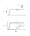
- FIG. 5 is a diagram illustrating a control result by the driving force control method of the present embodiment.
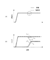
- FIG. 6 shows a control result when the driving force control method of the present embodiment is not executed as a comparative example.
- FIGS. 5 and 6 show a scene (that is, moving torque) in which the output torque is moved from the front wheels 11f to the rear wheels 11r by slipping the rear wheels 11r in a low torque region such as when starting on a low ⁇ road.
- the quantity ⁇ T * m > 0) is assumed.
- the rear inverter 12r has a lower communication response to the command signal of the controller 50 than the front inverter 12f.
- the control of the comparative example shown in FIG. 6 differs from the driving force control method of the present embodiment in that the upper limit of the change speed C r of the moving torque amount ⁇ T * m is always set to the second upper limit value C r_lim2 .
- the actual front torque T f_r with respect to the final front torque command value T ** fm due to the difference in communication responsiveness between the front wheel side and the rear wheel side described above.
- the followability of the actual rear torque T r_r with respect to the final rear torque command value T ** mr is lower than the followability of.
- the upper limit of the change speed C r of the moving torque amount ⁇ T * m is limited to the first upper limit value C r_lim1 smaller than the second upper limit value C r_lim2 .
- the difference in followability with respect to the command value between the actual rear torque T r_r and the actual front torque T f_r can be alleviated (see FIG. 5B).
- the generation of a step between the front and rear G during torque movement is suppressed (see FIG. 5A).
- the vehicle 100 includes a front motor 10f as a first motor for driving the front wheels 11f and a rear motor 10r as a second motor for driving the rear wheels 11r, and is driven according to the traveling state of the vehicle 100.
- a driving force control method is provided in which the required driving force (total required torque T * mfr ) is distributed by a predetermined distribution ratio (distribution ratio ⁇ ) and output by the front motor 10f and the rear motor 10r.
- the output torque is moved from the rear motor 10r as one motor to the front motor 10f as the other motor according to the change in the distribution ratio ⁇ based on the traveling state of the vehicle 100, and the vehicle 100 slips.
- a slip state parameter front / rear wheel speed difference ⁇ w mfr or slip control intervention flag f FB ) indicating the state is set.
- the first upper limit value C r_lim1 is set to a constant value with respect to the change in the total required torque T * mfr .
- the torque threshold value T mfr_th is determined from the viewpoint of determining the starting scene of the vehicle 100.
- the slip state parameter includes a front / rear wheel speed difference ⁇ w mfr , which is a difference in rotational speed between the front wheels 11f and the rear wheels 11r, and a predetermined speed difference threshold value (front / rear) as a threshold value of the slip state parameter.
- Wheel speed difference threshold ⁇ w mfr_Th is set. Then, the output torque of the front wheels 11f and the rear wheels 11r to be moved from the slip wheels to the non-slip wheels is corrected so that the front-rear wheel speed difference ⁇ w mfr approaches the front-rear wheel speed difference threshold value ⁇ w mfr_Th ( movement torque amount ⁇ T *). Correct m to obtain the corrected rear torque T * m ).
- the actual slip state of the vehicle 100 can be more appropriately determined based on the front-rear wheel speed difference ⁇ w mfr , which is a specific index of whether or not slip has occurred in the front wheels 11f or the rear wheels 11r.
- the upper limit of the change speed C r can be set to the first upper limit value C r_lim1 or the second upper limit value C r_lim2 more appropriately according to the scene.
- the final rear torque command value T ** mr as the torque command value of the rear motor 10r determined by limiting the movement torque amount ⁇ T * m by the first upper limit value C r_lim1 or the second upper limit value C r_lim2 is set.
- the final rear torque command value T ** mr is subtracted from the total required torque T * mfr to calculate the final front torque command value T ** fm , which is the torque command value of the front motor 10f.
- the output torques of the front motor 10f and the rear motor 10r are controlled based on the final front torque command value T ** fm and the final rear torque command value T ** mr .
- This provides a specific calculation mode for achieving a suitable balance between suppressing the change in the front-rear G and maintaining the responsiveness related to the torque control described above.
- a driving force control device for executing the above driving force control method is provided.
- This driving force control device (controller 50) is executed in the vehicle 100 including the front motor 10f as the first motor for driving the front wheels 11f and the rear motor 10r as the second motor for driving the rear wheels 11r, and the vehicle 100 travels.
- the required driving force (total required torque T * mfr ) for driving is distributed by a predetermined distribution ratio (distribution ratio ⁇ ) according to the state, and is output by the front motor 10f and the rear motor 10r.
- the controller 50 as the driving force control device moves the output torque from the rear motor 10r as one motor to the front motor 10f as the other motor according to the change of the distribution ratio ⁇ based on the traveling state of the vehicle 100.
- a slip state parameter setting unit (slip control unit 54) that sets a torque moving unit (rate limit unit 56) and a slip state parameter (front-rear wheel speed difference ⁇ w mfr and slip control intervention flag f FB ) indicating the slip state of the vehicle 100.
- a change speed limiting unit (rate limit unit 56) that limits the change speed C r of the moving torque amount ⁇ T * m .
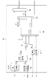
- FIG. 7 is a block diagram illustrating the configuration of the controller 50 in the present embodiment.
- the slip control unit 54 is composed of a front-rear slip control unit 54-1 and a lateral slip control unit 54-2.
- the front-rear slip control unit 54-1 performs the same processing as the slip control unit 54 of the first embodiment. That is, the front-rear slip control unit 54-1 performs feedback control so as to suppress the slip of the front wheels 11f or the rear wheels 11r of the vehicle 100.
- the lateral slip control unit 54-2 controls to suppress slip in the lateral direction (rotational direction around the center of gravity of the vehicle) of the vehicle 100, which may occur in a scene such as a sharp turn.
- a yaw rate YR detected by a yaw rate sensor (not shown) is input to the lateral slip control unit 54-2.
- the lateral slip control unit 54-2 calculates a correction torque TYR determined to eliminate the lateral slip of the vehicle 100 based on the input yaw rate YR .
- the lateral slip control unit 54-2 sets the lateral slip control intervention flag f YR to “1” when the calculated correction torque TYR is equal to or higher than a predetermined threshold value. Further, when the calculated correction torque TYR is less than a predetermined threshold value, the lateral slip control intervention flag f YR is set to “0”.
- the threshold value to be compared with the correction torque TYR is a value suitable from the viewpoint of determining whether or not the vehicle 100 needs to be corrected in the total required torque T * mfr to some extent in the lateral slip direction. Is set to. Then, the lateral slip control unit 54-2 outputs the calculated correction torque TYR to the required torque correction unit 62, and outputs the set lateral slip control intervention flag f YR to the rate limit unit 56.
- the required torque correction unit 62 calculates the corrected total required torque T ′ * mfr by inputting the total required torque T * mfr from the total required torque calculation unit 52 and the correction torque TYR from the lateral slip control unit 54-2. Then, the required torque correction unit 62 outputs the calculated corrected total required torque T'* mfr to the torque distribution unit 53. Therefore, in the calculation after the torque distribution unit 53 described in the first embodiment, the corrected total required torque T ′ * mfr is used instead of the total required torque T * mfr .
- the lateral slip control intervention flag f YR is input to the rate limit unit 56 as a flag (slip state parameter) indicating the slip state of the vehicle 100. Then, in step S120 shown in FIG. 3, the rate limit unit 56 executes the processes after step S130 when both the slip control intervention flag f FB and the lateral slip control intervention flag f YR are set to “0”. do. On the other hand, when at least one of the slip control intervention flag f FB and the lateral slip control intervention flag f YR is set to "1", the rate limit unit 56 is either a front-rear slip or a lateral slip of the vehicle 100. If it occurs), the processes after step S150 are executed.
- the upper limit of the change speed C r of the moving torque amount ⁇ T * m is relatively large even when slip occurs not only in the front-rear direction but also in the lateral direction of the vehicle 100, which is the second upper limit value. It will be set to C r_lim2 . Therefore, when a slip occurs in the vehicle 100, regardless of whether it is a front- rear slip or a lateral slip, the limitation of the change speed Cr of the moving torque amount ⁇ T * m is relaxed and the torque control is performed. The responsiveness can be improved and the slip can be quickly eliminated.
- the final rear torque command value T ** mr determined by limiting the movement torque amount ⁇ T * m by the first upper limit value C r_lim1 or the second upper limit value C r_lim2 is calculated, and the total required torque T * is calculated.
- An example of calculating the final front torque command value T ** fm by subtracting the final rear torque command value T ** mr from mfr has been described.
- the present invention is not limited to this, and for example, the final front torque command value T ** fm determined by limiting the movement torque amount ⁇ T * m by the first upper limit value C r_lim1 or the second upper limit value C r_lim2 is calculated, and the total request is made.
- a configuration may be adopted in which the final front torque command value T ** fm is subtracted from the torque T * mfr to calculate the final rear torque command value T ** mr .
- the rear inverter 12r has a lower communication responsiveness to the command signal of the controller 50 than the front inverter 12f.
- the control configuration described in the above embodiment is the same by exchanging the positions of the front wheel side and the rear wheel side. Can be applied to.
Landscapes
- Engineering & Computer Science (AREA)
- Transportation (AREA)
- Mechanical Engineering (AREA)
- Power Engineering (AREA)
- Life Sciences & Earth Sciences (AREA)
- Sustainable Development (AREA)
- Sustainable Energy (AREA)
- Chemical & Material Sciences (AREA)
- Combustion & Propulsion (AREA)
- Electric Propulsion And Braking For Vehicles (AREA)
Abstract
Description
以下、第1実施形態について説明する。 [First Embodiment]
Hereinafter, the first embodiment will be described.
以下、第2実施形態について説明する。なお、第1実施形態と同様の要素には同一の符号を付し、その説明を省略する。 [Second Embodiment]
Hereinafter, the second embodiment will be described. The same elements as those in the first embodiment are designated by the same reference numerals, and the description thereof will be omitted.
Claims (6)
- 前輪を駆動する第1電動機と後輪を駆動する第2電動機を備える車両において実行され、前記車両の走行状態に応じて走行駆動用の要求駆動力を所定の配分比で分配して前記第1電動機及び前記第2電動機により出力させる駆動力制御方法であって、
前記車両の走行状態に基づく前記配分比の変化に応じて、一方の電動機から他方の電動機に出力トルクを移動させ、
前記車両のスリップ状態を表すスリップ状態パラメータを設定し、
前記スリップ状態パラメータが所定の閾値以下である場合に、移動させる前記出力トルクの変化速度の上限を相対的に小さい第1上限値に設定し、
前記スリップ状態パラメータが前記閾値を超える場合に、前記変化速度の上限を相対的に大きい第2上限値に設定する、
駆動力制御方法。 It is executed in a vehicle equipped with a first electric motor for driving the front wheels and a second electric motor for driving the rear wheels, and the required driving force for driving is distributed in a predetermined distribution ratio according to the traveling state of the vehicle. It is a driving force control method to output by an electric motor and the second electric motor.
The output torque is moved from one motor to the other according to the change in the distribution ratio based on the running state of the vehicle.
A slip state parameter indicating the slip state of the vehicle is set, and the slip state parameter is set.
When the slip state parameter is equal to or less than a predetermined threshold value, the upper limit of the change speed of the output torque to be moved is set to a relatively small first upper limit value.
When the slip state parameter exceeds the threshold value, the upper limit of the change rate is set to a relatively large second upper limit value.
Driving force control method. - 請求項1に記載の駆動力制御方法であって、
前記要求駆動力が大きいほど、前記第1上限値を大きく設定する、
駆動力制御方法。 The driving force control method according to claim 1.
The larger the required driving force, the larger the first upper limit value is set.
Driving force control method. - 請求項2に記載の駆動力制御方法であって、
前記要求駆動力が所定の駆動力閾値以下である場合には、前記第1上限値を前記要求駆動力の変化に対する一定値に設定し、
前記要求駆動力が前記駆動力閾値を超える場合には、前記第1上限値を前記要求駆動力の増加に応じて増加する変動値に設定し、
前記駆動力閾値は、前記車両の発進シーンを判断する観点から定められる、
駆動力制御方法。 The driving force control method according to claim 2.
When the required driving force is equal to or less than a predetermined driving force threshold value, the first upper limit value is set to a constant value with respect to the change in the required driving force.
When the required driving force exceeds the driving force threshold value, the first upper limit value is set to a variable value that increases with an increase in the required driving force.
The driving force threshold value is determined from the viewpoint of determining the starting scene of the vehicle.
Driving force control method. - 請求項1~3の何れか1項に記載の駆動力制御方法であって、
前記スリップ状態パラメータは、前記前輪と前記後輪の間の回転速度の差である前後輪速度差を含み、
前記閾値として所定の速度差閾値を設定し、
前記前後輪速度差が前記速度差閾値に近づくように、前記前輪及び前記後輪のうちのスリップ輪から非スリップ輪に移動させる前記出力トルクを補正する、
駆動力制御方法。 The driving force control method according to any one of claims 1 to 3.
The slip state parameter includes a front-rear wheel speed difference, which is a difference in rotational speed between the front wheel and the rear wheel.
A predetermined speed difference threshold is set as the threshold, and the threshold is set.
The output torque to be moved from the slip wheel among the front wheel and the rear wheel to the non-slip wheel is corrected so that the front-rear wheel speed difference approaches the speed difference threshold value.
Driving force control method. - 請求項1~4の何れか1項に記載の駆動力制御方法であって、
移動させる前記出力トルクを前記第1上限値又は前記第2上限値により制限したことで定まる前記第2電動機のトルク指令値を演算し、
前記要求駆動力から前記第2電動機のトルク指令値を減算して前記第1電動機のトルク指令値を演算し、
前記第1電動機のトルク指令値及び前記第2電動機のトルク指令値に基づいて、前記第1電動機及び前記第2電動機のそれぞれの前記出力トルクを制御する、
駆動力制御方法。 The driving force control method according to any one of claims 1 to 4.
The torque command value of the second motor, which is determined by limiting the output torque to be moved by the first upper limit value or the second upper limit value, is calculated.
The torque command value of the second motor is subtracted from the required driving force to calculate the torque command value of the first motor.
The output torques of the first motor and the second motor are controlled based on the torque command value of the first motor and the torque command value of the second motor.
Driving force control method. - 前輪を駆動する第1電動機と後輪を駆動する第2電動機を備える車両において実行され、前記車両の走行状態に応じて走行駆動用の要求駆動力を所定の配分比で分配して前記第1電動機及び前記第2電動機により出力させる駆動力制御装置であって、
前記車両の走行状態に基づく前記配分比の変化に応じて、一方の電動機から他方の電動機に出力トルクを移動させるトルク移動部と、
前記車両のスリップ状態を表すスリップ状態パラメータを設定するスリップ状態パラメータ設定部と、
移動させる前記出力トルクの変化速度を制限する変化速度制限部と、を有し、
前記変化速度制限部は、
前記スリップ状態パラメータが所定の閾値以下である場合に、移動させる前記出力トルクの変化速度の上限を相対的に小さい第1上限値に設定し、
前記スリップ状態パラメータが前記閾値を超える場合に、移動させる前記出力トルクの変化速度の上限を相対的に大きい第2上限値に設定する、
駆動力制御装置。 It is executed in a vehicle equipped with a first electric motor for driving the front wheels and a second electric motor for driving the rear wheels, and the required driving force for driving is distributed in a predetermined distribution ratio according to the traveling state of the vehicle. A driving force control device that is output by an electric motor and the second electric motor.
A torque moving unit that moves the output torque from one motor to the other according to the change in the distribution ratio based on the running state of the vehicle.
A slip state parameter setting unit for setting a slip state parameter representing the slip state of the vehicle, and a slip state parameter setting unit.
It has a change speed limiting unit that limits the change speed of the output torque to be moved.
The change rate limiting unit is
When the slip state parameter is equal to or less than a predetermined threshold value, the upper limit of the change speed of the output torque to be moved is set to a relatively small first upper limit value.
When the slip state parameter exceeds the threshold value, the upper limit of the change speed of the output torque to be moved is set to a relatively large second upper limit value.
Driving force control device.
Priority Applications (6)
| Application Number | Priority Date | Filing Date | Title |
|---|---|---|---|
| EP20958635.3A EP4238810A4 (en) | 2020-10-20 | 2020-10-20 | Driving force control method and driving force control device |
| PCT/JP2020/039416 WO2022085082A1 (en) | 2020-10-20 | 2020-10-20 | Driving force control method and driving force control device |
| CN202080106352.9A CN116323292A (en) | 2020-10-20 | 2020-10-20 | Driving force control method and driving force control device |
| US18/032,642 US20230391204A1 (en) | 2020-10-20 | 2020-10-20 | Driving Force Control Method and Driving Force Control Device |
| MX2023004460A MX2023004460A (en) | 2020-10-20 | 2020-10-20 | Driving force control method and driving force control device. |
| JP2022556864A JP7359318B2 (en) | 2020-10-20 | 2020-10-20 | Driving force control method and driving force control device |
Applications Claiming Priority (1)
| Application Number | Priority Date | Filing Date | Title |
|---|---|---|---|
| PCT/JP2020/039416 WO2022085082A1 (en) | 2020-10-20 | 2020-10-20 | Driving force control method and driving force control device |
Publications (1)
| Publication Number | Publication Date |
|---|---|
| WO2022085082A1 true WO2022085082A1 (en) | 2022-04-28 |
Family
ID=81290327
Family Applications (1)
| Application Number | Title | Priority Date | Filing Date |
|---|---|---|---|
| PCT/JP2020/039416 WO2022085082A1 (en) | 2020-10-20 | 2020-10-20 | Driving force control method and driving force control device |
Country Status (6)
| Country | Link |
|---|---|
| US (1) | US20230391204A1 (en) |
| EP (1) | EP4238810A4 (en) |
| JP (1) | JP7359318B2 (en) |
| CN (1) | CN116323292A (en) |
| MX (1) | MX2023004460A (en) |
| WO (1) | WO2022085082A1 (en) |
Citations (4)
| Publication number | Priority date | Publication date | Assignee | Title |
|---|---|---|---|---|
| JP2006246607A (en) * | 2005-03-03 | 2006-09-14 | Toyota Motor Corp | Vehicle and its control method |
| JP2007221894A (en) * | 2006-02-15 | 2007-08-30 | Toyota Motor Corp | Controller for electric vehicle |
| JP2013193524A (en) * | 2012-03-16 | 2013-09-30 | Toyota Motor Corp | Braking force control device |
| JP5835583B2 (en) | 2012-04-27 | 2015-12-24 | 三菱自動車工業株式会社 | Driving force control device for electric vehicle |
Family Cites Families (3)
| Publication number | Priority date | Publication date | Assignee | Title |
|---|---|---|---|---|
| JP4842011B2 (en) * | 2006-05-10 | 2011-12-21 | 日立オートモティブシステムズ株式会社 | Electric motor control device |
| JP6350003B2 (en) * | 2014-06-19 | 2018-07-04 | 三菱自動車工業株式会社 | Vehicle control device |
| JP2019188923A (en) * | 2018-04-20 | 2019-10-31 | トヨタ自動車株式会社 | Control device of four-wheel drive vehicle |
-
2020
- 2020-10-20 EP EP20958635.3A patent/EP4238810A4/en active Pending
- 2020-10-20 JP JP2022556864A patent/JP7359318B2/en active Active
- 2020-10-20 WO PCT/JP2020/039416 patent/WO2022085082A1/en unknown
- 2020-10-20 US US18/032,642 patent/US20230391204A1/en active Pending
- 2020-10-20 MX MX2023004460A patent/MX2023004460A/en unknown
- 2020-10-20 CN CN202080106352.9A patent/CN116323292A/en active Pending
Patent Citations (4)
| Publication number | Priority date | Publication date | Assignee | Title |
|---|---|---|---|---|
| JP2006246607A (en) * | 2005-03-03 | 2006-09-14 | Toyota Motor Corp | Vehicle and its control method |
| JP2007221894A (en) * | 2006-02-15 | 2007-08-30 | Toyota Motor Corp | Controller for electric vehicle |
| JP2013193524A (en) * | 2012-03-16 | 2013-09-30 | Toyota Motor Corp | Braking force control device |
| JP5835583B2 (en) | 2012-04-27 | 2015-12-24 | 三菱自動車工業株式会社 | Driving force control device for electric vehicle |
Non-Patent Citations (1)
| Title |
|---|
| See also references of EP4238810A4 |
Also Published As
| Publication number | Publication date |
|---|---|
| MX2023004460A (en) | 2023-04-28 |
| US20230391204A1 (en) | 2023-12-07 |
| JP7359318B2 (en) | 2023-10-11 |
| JPWO2022085082A1 (en) | 2022-04-28 |
| EP4238810A1 (en) | 2023-09-06 |
| EP4238810A4 (en) | 2024-03-13 |
| CN116323292A (en) | 2023-06-23 |
Similar Documents
| Publication | Publication Date | Title |
|---|---|---|
| US11021068B2 (en) | Vehicle control device and control method | |
| US10780878B2 (en) | Vehicle turning control device | |
| US10189356B2 (en) | Vehicle control device and vehicle control method | |
| WO2018138780A1 (en) | Electric vehicle control method and control device | |
| US20160347202A1 (en) | Control device for electric motor vehicle and control method for electric motor vehicle | |
| JP6760401B2 (en) | Electric vehicle control method and control device | |
| WO2016121546A1 (en) | Vehicle orientation control device | |
| WO2018139375A1 (en) | Method for controlling electrically driven vehicle and device for controlling electrically driven vehicle | |
| JP2012029473A (en) | Control device for electric vehicle | |
| JP2017210088A (en) | Turn control device of vehicle | |
| WO2019059131A1 (en) | Vehicle control device | |
| JP2021044975A (en) | Control device for vehicle | |
| JP7449109B2 (en) | Vehicle control device | |
| JP7176360B2 (en) | electric vehicle | |
| JP7056219B2 (en) | Motor vehicle control method and motor vehicle control device | |
| JP2016111878A (en) | Drive torque controller of vehicle | |
| WO2022085082A1 (en) | Driving force control method and driving force control device | |
| JP6880674B2 (en) | Electric vehicle control method and electric vehicle control device | |
| WO2015019399A1 (en) | Vehicle vibration suppression control device | |
| JP2016111779A (en) | Vehicle driving force control device | |
| JP2016163459A (en) | Driving force control device for vehicle | |
| JP2016101847A (en) | Vehicular drive force control apparatus | |
| JP2020205682A (en) | Electric-vehicular control method and control apparatus | |
| WO2023032012A1 (en) | Control method for electric motor vehicle and control device for electric motor vehicle | |
| WO2023233905A1 (en) | Control device for mobile object, and program |
Legal Events
| Date | Code | Title | Description |
|---|---|---|---|
| 121 | Ep: the epo has been informed by wipo that ep was designated in this application |
Ref document number: 20958635 Country of ref document: EP Kind code of ref document: A1 |
|
| ENP | Entry into the national phase |
Ref document number: 2022556864 Country of ref document: JP Kind code of ref document: A |
|
| REG | Reference to national code |
Ref country code: BR Ref legal event code: B01A Ref document number: 112023006903 Country of ref document: BR |
|
| ENP | Entry into the national phase |
Ref document number: 112023006903 Country of ref document: BR Kind code of ref document: A2 Effective date: 20230413 |
|
| NENP | Non-entry into the national phase |
Ref country code: DE |
|
| ENP | Entry into the national phase |
Ref document number: 2020958635 Country of ref document: EP Effective date: 20230522 |