WO2022080343A1 - 核酸検出装置および核酸の検出方法 - Google Patents
核酸検出装置および核酸の検出方法 Download PDFInfo
- Publication number
- WO2022080343A1 WO2022080343A1 PCT/JP2021/037659 JP2021037659W WO2022080343A1 WO 2022080343 A1 WO2022080343 A1 WO 2022080343A1 JP 2021037659 W JP2021037659 W JP 2021037659W WO 2022080343 A1 WO2022080343 A1 WO 2022080343A1
- Authority
- WO
- WIPO (PCT)
- Prior art keywords
- nucleic acid
- fluorescence
- detection device
- effector protein
- acid detection
- Prior art date
- Legal status (The legal status is an assumption and is not a legal conclusion. Google has not performed a legal analysis and makes no representation as to the accuracy of the status listed.)
- Ceased
Links
Images


Classifications
-
- C—CHEMISTRY; METALLURGY
- C12—BIOCHEMISTRY; BEER; SPIRITS; WINE; VINEGAR; MICROBIOLOGY; ENZYMOLOGY; MUTATION OR GENETIC ENGINEERING
- C12Q—MEASURING OR TESTING PROCESSES INVOLVING ENZYMES, NUCLEIC ACIDS OR MICROORGANISMS; COMPOSITIONS OR TEST PAPERS THEREFOR; PROCESSES OF PREPARING SUCH COMPOSITIONS; CONDITION-RESPONSIVE CONTROL IN MICROBIOLOGICAL OR ENZYMOLOGICAL PROCESSES
- C12Q1/00—Measuring or testing processes involving enzymes, nucleic acids or microorganisms; Compositions therefor; Processes of preparing such compositions
- C12Q1/68—Measuring or testing processes involving enzymes, nucleic acids or microorganisms; Compositions therefor; Processes of preparing such compositions involving nucleic acids
- C12Q1/6806—Preparing nucleic acids for analysis, e.g. for polymerase chain reaction [PCR] assay
-
- C—CHEMISTRY; METALLURGY
- C12—BIOCHEMISTRY; BEER; SPIRITS; WINE; VINEGAR; MICROBIOLOGY; ENZYMOLOGY; MUTATION OR GENETIC ENGINEERING
- C12M—APPARATUS FOR ENZYMOLOGY OR MICROBIOLOGY; APPARATUS FOR CULTURING MICROORGANISMS FOR PRODUCING BIOMASS, FOR GROWING CELLS OR FOR OBTAINING FERMENTATION OR METABOLIC PRODUCTS, i.e. BIOREACTORS OR FERMENTERS
- C12M1/00—Apparatus for enzymology or microbiology
- C12M1/34—Measuring or testing with condition measuring or sensing means, e.g. colony counters
-
- C—CHEMISTRY; METALLURGY
- C12—BIOCHEMISTRY; BEER; SPIRITS; WINE; VINEGAR; MICROBIOLOGY; ENZYMOLOGY; MUTATION OR GENETIC ENGINEERING
- C12N—MICROORGANISMS OR ENZYMES; COMPOSITIONS THEREOF; PROPAGATING, PRESERVING, OR MAINTAINING MICROORGANISMS; MUTATION OR GENETIC ENGINEERING; CULTURE MEDIA
- C12N15/00—Mutation or genetic engineering; DNA or RNA concerning genetic engineering, vectors, e.g. plasmids, or their isolation, preparation or purification; Use of hosts therefor
- C12N15/09—Recombinant DNA-technology
- C12N15/11—DNA or RNA fragments; Modified forms thereof; Non-coding nucleic acids having a biological activity
-
- C—CHEMISTRY; METALLURGY
- C12—BIOCHEMISTRY; BEER; SPIRITS; WINE; VINEGAR; MICROBIOLOGY; ENZYMOLOGY; MUTATION OR GENETIC ENGINEERING
- C12N—MICROORGANISMS OR ENZYMES; COMPOSITIONS THEREOF; PROPAGATING, PRESERVING, OR MAINTAINING MICROORGANISMS; MUTATION OR GENETIC ENGINEERING; CULTURE MEDIA
- C12N9/00—Enzymes; Proenzymes; Compositions thereof; Processes for preparing, activating, inhibiting, separating or purifying enzymes
- C12N9/14—Hydrolases (3)
- C12N9/16—Hydrolases (3) acting on ester bonds (3.1)
- C12N9/22—Ribonucleases [RNase]; Deoxyribonucleases [DNase]
-
- C—CHEMISTRY; METALLURGY
- C12—BIOCHEMISTRY; BEER; SPIRITS; WINE; VINEGAR; MICROBIOLOGY; ENZYMOLOGY; MUTATION OR GENETIC ENGINEERING
- C12Q—MEASURING OR TESTING PROCESSES INVOLVING ENZYMES, NUCLEIC ACIDS OR MICROORGANISMS; COMPOSITIONS OR TEST PAPERS THEREFOR; PROCESSES OF PREPARING SUCH COMPOSITIONS; CONDITION-RESPONSIVE CONTROL IN MICROBIOLOGICAL OR ENZYMOLOGICAL PROCESSES
- C12Q1/00—Measuring or testing processes involving enzymes, nucleic acids or microorganisms; Compositions therefor; Processes of preparing such compositions
- C12Q1/68—Measuring or testing processes involving enzymes, nucleic acids or microorganisms; Compositions therefor; Processes of preparing such compositions involving nucleic acids
- C12Q1/6813—Hybridisation assays
- C12Q1/6816—Hybridisation assays characterised by the detection means
-
- G—PHYSICS
- G01—MEASURING; TESTING
- G01N—INVESTIGATING OR ANALYSING MATERIALS BY DETERMINING THEIR CHEMICAL OR PHYSICAL PROPERTIES
- G01N21/00—Investigating or analysing materials by the use of optical means, i.e. using sub-millimetre waves, infrared, visible or ultraviolet light
- G01N21/62—Systems in which the material investigated is excited whereby it emits light or causes a change in wavelength of the incident light
- G01N21/63—Systems in which the material investigated is excited whereby it emits light or causes a change in wavelength of the incident light optically excited
- G01N21/64—Fluorescence; Phosphorescence
- G01N21/6428—Measuring fluorescence of fluorescent products of reactions or of fluorochrome labelled reactive substances, e.g. measuring quenching effects, using measuring "optrodes"
-
- G—PHYSICS
- G01—MEASURING; TESTING
- G01N—INVESTIGATING OR ANALYSING MATERIALS BY DETERMINING THEIR CHEMICAL OR PHYSICAL PROPERTIES
- G01N21/00—Investigating or analysing materials by the use of optical means, i.e. using sub-millimetre waves, infrared, visible or ultraviolet light
- G01N21/62—Systems in which the material investigated is excited whereby it emits light or causes a change in wavelength of the incident light
- G01N21/63—Systems in which the material investigated is excited whereby it emits light or causes a change in wavelength of the incident light optically excited
- G01N21/64—Fluorescence; Phosphorescence
- G01N21/645—Specially adapted constructive features of fluorimeters
- G01N21/6452—Individual samples arranged in a regular 2D-array, e.g. multiwell plates
-
- G—PHYSICS
- G01—MEASURING; TESTING
- G01N—INVESTIGATING OR ANALYSING MATERIALS BY DETERMINING THEIR CHEMICAL OR PHYSICAL PROPERTIES
- G01N21/00—Investigating or analysing materials by the use of optical means, i.e. using sub-millimetre waves, infrared, visible or ultraviolet light
- G01N21/62—Systems in which the material investigated is excited whereby it emits light or causes a change in wavelength of the incident light
- G01N21/63—Systems in which the material investigated is excited whereby it emits light or causes a change in wavelength of the incident light optically excited
- G01N21/64—Fluorescence; Phosphorescence
- G01N21/645—Specially adapted constructive features of fluorimeters
- G01N21/6456—Spatial resolved fluorescence measurements; Imaging
-
- C—CHEMISTRY; METALLURGY
- C12—BIOCHEMISTRY; BEER; SPIRITS; WINE; VINEGAR; MICROBIOLOGY; ENZYMOLOGY; MUTATION OR GENETIC ENGINEERING
- C12N—MICROORGANISMS OR ENZYMES; COMPOSITIONS THEREOF; PROPAGATING, PRESERVING, OR MAINTAINING MICROORGANISMS; MUTATION OR GENETIC ENGINEERING; CULTURE MEDIA
- C12N2310/00—Structure or type of the nucleic acid
- C12N2310/10—Type of nucleic acid
- C12N2310/20—Type of nucleic acid involving clustered regularly interspaced short palindromic repeats [CRISPR]
-
- G—PHYSICS
- G01—MEASURING; TESTING
- G01N—INVESTIGATING OR ANALYSING MATERIALS BY DETERMINING THEIR CHEMICAL OR PHYSICAL PROPERTIES
- G01N21/00—Investigating or analysing materials by the use of optical means, i.e. using sub-millimetre waves, infrared, visible or ultraviolet light
- G01N21/62—Systems in which the material investigated is excited whereby it emits light or causes a change in wavelength of the incident light
- G01N21/63—Systems in which the material investigated is excited whereby it emits light or causes a change in wavelength of the incident light optically excited
- G01N21/64—Fluorescence; Phosphorescence
- G01N21/6428—Measuring fluorescence of fluorescent products of reactions or of fluorochrome labelled reactive substances, e.g. measuring quenching effects, using measuring "optrodes"
- G01N2021/6439—Measuring fluorescence of fluorescent products of reactions or of fluorochrome labelled reactive substances, e.g. measuring quenching effects, using measuring "optrodes" with indicators, stains, dyes, tags, labels, marks
-
- G—PHYSICS
- G01—MEASURING; TESTING
- G01N—INVESTIGATING OR ANALYSING MATERIALS BY DETERMINING THEIR CHEMICAL OR PHYSICAL PROPERTIES
- G01N21/00—Investigating or analysing materials by the use of optical means, i.e. using sub-millimetre waves, infrared, visible or ultraviolet light
- G01N21/62—Systems in which the material investigated is excited whereby it emits light or causes a change in wavelength of the incident light
- G01N21/63—Systems in which the material investigated is excited whereby it emits light or causes a change in wavelength of the incident light optically excited
- G01N21/64—Fluorescence; Phosphorescence
- G01N21/6408—Fluorescence; Phosphorescence with measurement of decay time, time resolved fluorescence
-
- G—PHYSICS
- G01—MEASURING; TESTING
- G01N—INVESTIGATING OR ANALYSING MATERIALS BY DETERMINING THEIR CHEMICAL OR PHYSICAL PROPERTIES
- G01N2201/00—Features of devices classified in G01N21/00
- G01N2201/12—Circuits of general importance; Signal processing
- G01N2201/124—Sensitivity
- G01N2201/1247—Thresholding
Definitions
- the present invention relates to a nucleic acid detection device and a nucleic acid detection method using a trans-cleaving reaction of the CHRISPR-Cas technique and an individual independent separation compartment.
- Non-Patent Document 1 The complex consisting of Cas12a and crRNA specifically recognizes and binds to the sequence of the target DNA, and Cas12a cleaves the bound target DNA.
- Cas12a cleaves the single-stranded DNA of the reporter molecule by a trans-cleaving reaction.
- the fluorescent substance and the quencher are separated, and fluorescence is generated.
- the trans-cleaving reaction of Cas12a is activated to generate fluorescence from the fluorescent substance derived from the reporter molecule, so that the target DNA can be detected based on the fluorescence. ..
- Patent Document 1 Feng Zhang et al. Of Broad Institute disclosed a method for detecting a target RNA using a complex consisting of Cas13a and crRNA and a reporter molecule.
- the complex consisting of Cas13a and crRNA specifically recognizes and binds to the sequence of the target RNA, and Cas13a cleaves the bound target RNA.
- a reporter molecule in which the fluorescent substance and the quencher are linked by RNA is added to the reaction system, Cas13a cleaves the RNA at the linking portion, and fluorescence is generated. This makes it possible to detect the target RNA.
- Patent Document 1 describes that a sample containing a target RNA may be distributed to individual independent separation compartments.
- Non-Patent Document 1 and Patent Document 1 When attempting to detect a low-concentration target nucleic acid by the methods described in Non-Patent Document 1 and Patent Document 1, it was difficult to detect or it was necessary to detect the target nucleic acid after a step of amplifying the target nucleic acid. When the step of amplifying the target nucleic acid is included, there is a problem that the operation for amplification is complicated and time-consuming.
- an object of the present invention is to provide a nucleic acid detection device and a nucleic acid detection method for easily detecting a low-concentration target nucleic acid.
- the nucleic acid detection apparatus distributes a sample containing a target nucleic acid and a detection reagent containing an effector protein, a crRNA bound to the target nucleic acid, and a reporter molecule into a plurality of individual independent compartments.
- a partitioning unit an activating unit that activates the effector protein by binding of the crRNA to the target nucleic acid; and a fluorescence generating unit that modifies the reporter molecule with the activated effector protein to generate fluorescence;
- a nucleic acid detection unit that detects the nucleic acid; based on the detection result obtained by the fluorescence detection unit, the fluorescence intensity of the individual independent separation compartment is determined, and the individual independent separation compartment having a fluorescence intensity exceeding a predetermined threshold value. It is characterized by including a specific part for specifying;
- a sample containing a target nucleic acid and a plurality of individual independent separations of a detection reagent containing an effector protein, a crRNA bound to the target nucleic acid, and a reporter molecule are separated.
- a partitioning step that distributes to the compartment; an activation step that activates the effector protein by binding of the crRNA to the target nucleic acid; and a fluorescence generation that modifies the reporter molecule with the activated effector protein to generate fluorescence.
- the step and the fluorescence detection step of detecting the nucleic acid based on the detection result obtained in the step of detecting the nucleic acid, the fluorescence intensity of the individual independent separation compartment is determined, and the fluorescence intensity exceeding a predetermined threshold value is determined. It is characterized by having a specific step of specifying an individual independent separation section having;
- the program according to still another aspect of the present invention is a program for causing a computer included in the nucleic acid detection device to execute the nucleic acid detection method in the nucleic acid detection device.
- nucleic acid detection device and a nucleic acid detection method for easily detecting a low-concentration target nucleic acid.
- FIG. 1 is a functional block diagram of the nucleic acid detection device 10 according to the present invention.
- the nucleic acid detection device 10 has a distribution unit 101, an activation unit 102, a fluorescence generation unit 103, a fluorescence detection unit 104, and a specific unit 105.
- the distribution unit 101 distributes the sample containing the target nucleic acid and the detection reagent to a plurality of individual independent separation compartments.
- the detection reagent contains an effector protein, a crRNA that binds to the target nucleic acid, and a reporter molecule.
- the activation unit 102 activates the effector protein by binding the crRNA to the target nucleic acid.
- the fluorescence generator 103 modifies the reporter molecule with the activated effector protein to generate fluorescence.
- the fluorescence detection unit 104 detects fluorescence. Further, the specific unit 105 determines the fluorescence intensity of the individual independent separation section, and identifies the individual independent separation section having the fluorescence intensity exceeding a predetermined threshold value.
- the detection reagent may individually contain an effector protein, crRNA, and a reporter molecule.
- the sample containing the target nucleic acid may be premixed with the effector protein and crRNA before distribution to the individual independent separation compartment, and then the reporter molecule may be further mixed.
- the specific unit 105 has an extraction unit 106, a determination unit 107, a determination unit 108, a calculation unit 109, a display unit 110, and a storage unit 111. The functions of these configurations of the specific unit 105 will be described later.
- effector protein As the effector protein, for example, either Cas12 or Cas13 can be used.
- Cas12 for example, LbCas12a, AsCas12a, FnCas12a, AaCas12b and the like can be used.
- Cas13 for example, LwaCas13a, LbaCas13a, LbuCas13a, BzoCas13b, PinCas13b, PbuCas13b, AspCas13b, PsmCas13b, RanCas13b, PauCas13b, RanCas13b, PauCas13b, PsaCas13b, PsaCas13b, PsaCas13b, PsaCas13b, PsaCas13b, PsaCas13b, PsaCas13b, PsaCas13b, PsaCas13b, PsaCas13b, PsaCas13b, PsaCas13b, PsaCas13b, PsaCas13b, PsaCas13b, PsaCas13b, PsaCas13
- the crRNA is an RNA designed to contain a base sequence having complementarity with the base sequence of the target nucleic acid.
- the complex consisting of the effector protein and crRNA specifically binds to the target nucleic acid sequence due to the complementarity of crRNA.
- the crRNA is designed based on the type of effector protein used and the target region in the base sequence of the target nucleic acid.
- target nucleic acid examples include DNA and RNA.
- the target nucleic acid may be a nucleic acid that can be applied to diagnosis of a disease state, constitution diagnosis, or the like.
- diseases state examples include cancer, autoimmune diseases, and infectious diseases.
- infectious disease examples include infectious diseases caused by DNA virus, RNA virus, and the like.
- the target nucleic acid can be arbitrarily selected and is not limited to the above example.
- reporter molecule examples include a molecule in which a fluorescent substance and a quencher are linked by a single-stranded DNA, a molecule in which a fluorescent substance and a quencher are linked by RNA, and the like.
- the reporter molecule is preferably a molecule in which a fluorescent substance and a quencher are linked by a single-stranded DNA.
- a molecule in which a fluorescent substance and a quencher are linked by a single-stranded DNA for example, DNase Allert (IDT) can be used.
- IDTT DNase Allert
- the reporter molecule is preferably a molecule in which a fluorescent substance and a quencher are linked by RNA.
- the detection reagent preferably further contains an amino compound.
- the detection reagent may have the amino compound separately from other components, or may have the amino compound in a state of being mixed with any of the components.
- the amino compound is a compound containing an amino group, and in the present invention, any of a primary amine, a secondary amine, and a tertiary amine can be used as the amino compound.
- amino compound examples include pentaethylenehexamine (following formula (a1)), spermin (following formula (a2)), spermine tetrachloride, triethylenetetramine (following formula (a3)), and spermidin (following formula (a2)).
- Examples of the compound represented by the following formula (a19) include SUNBRIGHT (registered trademark) EA Series. Further, examples of the compound represented by the following formula (a20) include SUNBRIGHT (registered trademark) PA Series.
- n is 30 or more and 1000 or less.
- n is 30 or more and 1000 or less.
- n is 30 or more and 120 or less.
- the amino compound preferably has -NH 2 . Further, the amino compound has a plurality of -NH 2 or a plurality of -NH-, or has one or more of -NH 2 and -N (CH 3 ) -in each, or-in one molecule. It is more preferable to have one or more NH 2 and -NH- each. Further, it is more preferable that the amino compound has one or more -NH 2 and two or more -NH-, or has two or more -NH 2 and one or more -NH-.
- the detection reagent preferably contains a reaction buffer.
- the detection reagent may have a reaction buffer separate from the effector protein, crRNA, reporter molecule, and amino compound. Further, in the detection reagent, at least one selected from the group consisting of an effector protein, crRNA, a reporter molecule, and an amino compound may be dispersed in the reaction buffer.
- reaction buffer examples include a Tris-based buffer that has been used in an enzymatic reaction using Cas12a or Cas13a, a HEPES-based buffer, and the like.
- Binding buffer (20 mM Tis-HCl (pH 7.6), 100 mM KCl, 5 mM MgCl 2 , 1 mM DTT, 5% glycerol, 50 ⁇ g / mL heparin), NE Buffer (registered trademark) 2.1 (10 mM).
- Tris-HCl 50 mM NaCl, 10 mM MgCl 2 , 100 ⁇ g / mL BSA, pH 7.9), FZ buffer (20 mM HEPES, 60 mM NaCl, 6 mM MgCl 2 , pH 6.8) and the like.
- the effector protein is preferably bound to the particles.
- the type of particles bound to the effector protein is not particularly limited as long as the effector protein can be bound.
- the particles may be primary particles or secondary particles in which primary particles are aggregated.
- the bond is formed by a reaction using the carboxy group originally possessed by the particle. .. That is, it is preferable that the binding portion between the effector protein and the particle has a structure derived from the carboxy group bonded to the particle.
- the effector protein and the particles may be bound via an amide bond.
- C O derived from the carboxy group contained in the particles and NH derived from the amino group contained in the protein form an amide bond.
- the effector protein and the particles may be bound via a linker.
- the linker refers to a structure that forms a bond between an effector protein and a particle.
- the linker preferably contains a peptide consisting of 6 or more and 11 or less histidine residues in succession.
- the linker may further have an antibody (for example, an anti-His tag antibody) that binds to the peptide by an antigen-antibody reaction. That is, for example, when an effector protein having the peptide is reacted with a particle having an antibody that binds to the peptide to bind the particle and the effector protein, the linker has the peptide and the antibody. become.
- the particle and the antibody can be bound, for example, via an amide bond formed by reacting a carboxy group originally possessed by the particle with an amino group possessed by the antibody.
- a commercially available product for example, EnGen LbaCas12a (Cpf1) (trade name: M0653T, manufactured by NEB, 100 ⁇ M) or the like can be used.
- the linker may further have a metal complex that binds to the peptide. That is, the effector protein having the peptide and the particles having a metal complex may be reacted to bind the effector protein and the particles.
- the metal complex that binds to the peptide include a complex of nitrilotriacetic acid or iminodiacetic acid and a divalent nickel ion. It is particularly preferable that the peptide is a peptide in which 6 histidine residues are consecutive (hereinafter, may be referred to as a His tag).
- the binding part between the effector protein and the effector protein side linker was artificially inserted into the ⁇ -amino group of the lysine residue of the effector protein, the ⁇ -amino group of the N-terminal of the effector protein, and the N-terminal of the effector protein.
- Examples include various tag peptide sequences and tag proteins.
- Examples of the tag peptide include His tag, HA tag, DDDDK tag (FLAG (registered trademark)) and the like.
- examples of the tag protein include Halo-tag (registered trademark) and the like.
- the bonding portion between the particle and the linker various ones may be mentioned depending on the type of the linker.
- the structure used for binding to the linker on the particle side includes a carboxy group and an aldehyde group.
- a condensation reaction using N-hydroxysuccinimide (NHS) / water-soluble carbodiimide (WSC) can be used.
- an anti-His tag antibody can be used as a linker.
- a carboxy group of the particle is used as the particle-side linker, and the anti-His tag antibody is bound to the particle surface by a condensation reaction between the amino group of the anti-His tag antibody and NHS / WSC.
- the effector protein can be bound to the particles by using the antigen-antibody reaction between the His tag at the N-terminal of the effector protein and the anti-His tag antibody.
- a metal chelate ligand such as iminodiacetic acid or nitrilotriacetic acid is bound to the particles as a linker to form a coordinate bond via metal ions such as nickel ion and cobalt ion. This allows the effector protein to be immobilized on the particles.
- linkers include various tag peptide sequences, tag proteins and their affinity sites, complexes of avidin and biotin, and PEG having various functional groups at the ends. Further, the effector protein can be bound to the particle surface by physical adsorption or the like.
- the position of the effector protein that binds to the particles is preferably a position that does not inhibit the activity of the effector protein.
- the effector protein is known to have an active site on the carboxy-terminal (C-terminal) side, and a position away from the C-terminal side is preferable.
- the N-terminal is particularly preferable because it is separated from the C-terminal side and various tag peptides and tag proteins can be inserted.
- the effector protein and the particles may be bound to form a composite particle. Further, after binding the effector protein and the particle, crRNA may be bound to the effector protein to form a composite particle.
- the particle material examples include polymer resin (styrene resin, acrylic resin, etc.) particles, silica particles, resin particles, agarose carrier resin particles, metal particles, latex particles, and the like.
- polymer resin styrene resin, acrylic resin, etc.
- silica particles silica particles
- resin particles silica particles
- agarose carrier resin particles metal particles, latex particles, and the like.
- commercially available usable particles include Magnosphere® MS300, Magnosphere® MS160, PureProteome® Nickel Magnetic Beads and the like.
- the material of the particles it is preferable to use particles containing a paramagnetic substance such as iron, nickel, and magnetite, a ferromagnetic substance, a supermagnetic substance, and the like, but other particles may be used.
- magnetic particles it becomes easy to control the position of the effector protein by applying a magnetic field.
- the particle size of the particles is preferably 10 nm or more, and more preferably 1 ⁇ m or more and 10 ⁇ m or less.
- the distribution unit of the nucleic acid detection device may have a recovery unit, and the recovery unit may contain composite particles formed by binding an effector protein bound to particles and crRNA. Use to recover the target nucleic acid.
- the target nucleic acid can be substantially concentrate by recovering the target nucleic acid from the sample in the recovery unit and then dispersing the target nucleic acid in a medium having a smaller volume than that of the original sample. For example, by having a recovery unit, even if the target nucleic acid is discarded without being filled in the individual independent separation compartment, the target nucleic acid can be recovered by allowing the composite particles to act. After recovery, the target nucleic acid can be detected by filling the individual independent separation compartment with the composite particles that have captured the target nucleic acid. Further, for example, a trace amount of target nucleic acid dissolved in a sample such as blood or an aqueous solution can be captured by the composite particles and recovered.
- the target nucleic acid when the sample containing the target nucleic acid is a large volume solution, the target nucleic acid is captured by the composite particles and the composite particles holding the target nucleic acid are individually independent before being encapsulated in a minute individual independent separation compartment. It can be enclosed in a separation compartment. As a result, the loss of the target nucleic acid can be suppressed and the nucleic acid can be distributed to the individual independent separation compartments, and the target nucleic acid can be detected with high sensitivity. Further, if magnetic particles are used as the particles, the target nucleic acid can be easily recovered by using magnetism.
- the test reagent may further contain a blocking agent. That is, when the particle and the effector protein are bound, the portion of the linker binding portion of the particle to which the effector protein is not bound can be filled with the blocking agent.
- a blocking agent For example, when an amino group of an effector protein or an anti-His tag antibody and a carboxy group of a particle are subjected to a condensation reaction using NHS / WSC, the particle may have an unreacted carboxy group after the reaction. Therefore, the carboxy group that does not bind to the effector protein can be reacted with ethanolamine as a blocking agent, PEG having an amino group, or the like.
- the nucleic acid detection apparatus performs a trans-cleaving reaction of the CHRISPR-Cas technique in an individual independent separation compartment.
- the sample is apparently concentrated, the target nucleic acid is detected without going through the amplification step, and the time for which the fluorescent signal is saturated is set. It can be shortened.
- the target nucleic acid contained in one compartment can be set to be one molecule or less, and the number of compartments from which a fluorescent signal was obtained. By counting, it becomes possible to calculate the concentration of the target nucleic acid in the sample.
- Droplets and wells can be used as individual independent separation compartments.
- the droplets it is preferable to use a water-in-oil emulsion (W / O emulsion).
- W / O emulsion water-in-oil emulsion
- the well for example, a well having a well plate having the configurations shown in FIGS. 2A and 2B can be used.
- FIG. 2A is a cross-sectional view of the well plate 200
- FIG. 2B is a cross-sectional view of the well plate 200 in which the well 204 is filled with the composite particles 206 in which the complex of the effector protein and crRNA is bound to the particles.
- the well plate 200 includes a lower substrate 201, an upper substrate 202, an injection port portion (not shown), and a discharge port portion (not shown), and the lower substrate 201 is formed with a hydrophobic partition wall 203.
- a plurality of wells 204 are separated from each other by a partition wall 203.
- the lower substrate 201 preferably has a hydrophilic surface, and as the material of the lower substrate 201, for example, glass, silicon, a polymer resin, or the like can be used. Further, it is preferable that the surface of the upper substrate 202 (the surface facing the lower substrate 201) is hydrophobic.
- As the material of the partition wall 203 for example, a hydrophobic resin, a water-repellent resin, a fluoropolymer resin and the like can be used. Since the bottom surface of the well 204 is hydrophilic and the top surface of the partition wall 203 is hydrophobic, the solution can be efficiently filled in the well 204, and the excess solution is hydrophobic in the step of removing with a hydrophobic solvent. It is possible to prevent the sex solvent from entering the well 204.
- Well 204 is a recess for accommodating a solution, and is separated from each other by a partition wall 203.
- the well 204 has a lower substrate 201 as a bottom surface, and the shape of the region surrounded by the bottom surface and the side surface of the well 204 may be, for example, a cylindrical shape, a prismatic shape, or the like.
- the depth of the well 204 is the same as the height of the partition wall 203.
- the diameter of the well 204 is preferably 1 ⁇ m or more and 11 ⁇ m or less, and the depth of the well 204 is preferably 0.1 ⁇ m or more and 10 ⁇ m or less. Further, it is more preferable that the diameter of the well 204 is 1 ⁇ m or more and 7 ⁇ m or less, and the depth of the well 204 is 1 ⁇ m or more and 8 ⁇ m or less.
- the upper substrate 202 faces the opening of the well 204 and the upper surface of the partition wall 203 across a space 205.
- This space 205 is a flow path through which various liquids flow, and various liquids can flow from the injection port portion to the discharge port portion. That is, after the well 204 is filled with the solution, the space 205 is filled with the hydrophobic solvent.
- the composite particle 206 in which the complex of the effector protein and crRNA is bound to the particle is used, the composite particle 206 is filled in the well 204 and the space 205 is filled with the hydrophobic solvent.
- the hydrophobic solvent for example, fluorine oil, an aliphatic hydrocarbon or the like can be used.
- the volume of the individual independent separation section is preferably 0.1 fL or more and 1000 fL or less, and more preferably 0.5 fL or more and 400 fL or less.
- volume of the individual independent separation section is 0.1 fL or more, droplets or wells having the volume can be formed without difficulty. Further, if the volume of the individual independent separation section is 1000 fL or less, the detection time can be sufficiently shortened.
- the distributor 101 has, for example, an emulsified membrane or a microchannel.
- droplets can be prepared by using, for example, a direct membrane emulsification method or a pumping method such as SPG (Shirasu porous glass) film manufactured by SPG Techno.
- SPG Siliconemulsification method
- the distribution unit 101 having an emulsified film is used, for example, in a combination of Isopar L (aliphatic hydrocarbon, manufactured by ExxonMobil) and KF-6038 (surfactant, manufactured by Shin-Etsu Chemical Co., Ltd.), 0.6 to 12 ⁇ m. Droplets of diameter can be prepared.
- a microchannel manufactured by Dolomite can be used as the microchannel.
- droplets having a diameter of 2 to 10 ⁇ m can be prepared in the following two combinations. ⁇ Combination of Isopar L (aliphatic hydrocarbon, manufactured by ExxonMobil) and KF-6038 (surfactant, manufactured by Shin-Etsu Chemical Co., Ltd.) ⁇ Mineral oil (aliphatic hydrocarbon) and SPAN-80 (surfactant, Tokyo) Combination with (manufactured by Kaseisha)
- the distribution unit 101 has an injection unit, and the solution is injected into the well from the injection port portion of the well plate using, for example, an injection portion via a nozzle.
- the sample containing the target nucleic acid and the detection reagent may be mixed in advance before being distributed to the individual independent separation compartment and distributed as a reaction solution, or they may be individually distributed and individually independent. It may be mixed in the separation compartment. Since a uniformly mixed reaction solution can be easily obtained, it is preferable to mix the sample containing the target nucleic acid and the detection reagent in advance before distributing them to the individual independent separation compartments.
- the activation unit 102 binds the crRNA to the target nucleic acid by appropriately adjusting the environment such as temperature according to the sample, the sequence of the crRNA, the type of the effector protein, and the like, thereby activating the effector protein. ..
- an incubator can be used as the activating unit 102.
- the fluorescence generation unit 103 modifies the reporter molecule with the effector protein to generate fluorescence by appropriately adjusting the environment such as temperature according to the sample, the type of effector protein, the type of reporter molecule, and the like.
- an incubator can be used as the fluorescence generation unit 103.
- the activation unit 102 and the fluorescence generation unit 103 may be the same component in the nucleic acid detection device.
- the fluorescence detection unit 104 detects the fluorescence generated by the fluorescence generation unit 103.
- any device can be used as long as it can detect fluorescence in the individual independent separation compartment, and examples thereof include a plate reader and a fluorescence microscope.
- the extraction unit 106 extracts information on the number and relative positional relationship of the plurality of individual independent separation sections in the detection result obtained by the fluorescence detection unit 104.
- the determination unit 107 determines the fluorescence intensity in each individual independent separation section specified by the extraction unit 106 based on the detection result obtained by the fluorescence detection unit 104.
- the determination unit 108 determines an individual independent separation section having a fluorescence intensity exceeding a predetermined threshold value based on the fluorescence intensity determined by the determination unit 107. Thereby, an individual independent separation section having a fluorescence intensity exceeding a predetermined threshold value is specified.
- the identification unit 105 is configured to specify an individual independent separation section having a fluorescence intensity exceeding a predetermined threshold value based on the ratio of the fluorescence intensity in the reference section to the fluorescence intensity in the individual independent separation section. Is preferable. Further, the fluorescence intensity in the reference section is preferably the fluorescence intensity obtained by using the sample containing no target nucleic acid and the detection reagent. The fluorescence intensity of the reference compartment can be determined in the same manner as the individual independent separation compartment, except that the reference compartment does not contain the target nucleic acid.
- the ratio of the fluorescence intensity in the reference compartment to the fluorescence intensity in the individual independent separation compartment is calculated, for example, with the fluorescence intensity in the reference compartment as the denominator and the fluorescence intensity in the individual independent separation compartment as the numerator.
- the determination unit 108 considers that the fluorescence intensity of the individual independent separation section is equivalent to that of the reference section, and determines that it is negative. judge. Further, when the ratio of the fluorescence intensity in the reference section to the fluorescence intensity of the individual independent separation section is equal to or higher than a predetermined threshold value, the determination unit 108 determines that the individual independent separation section is positive.
- the calculation unit 109 calculates the concentration of the target nucleic acid in the sample based on the specified number of individual independent separation compartments having a fluorescence intensity exceeding a predetermined threshold.
- the specific unit 105 may not include the calculation unit 109.
- the display unit 110 displays the information acquired or extracted by the extraction unit 106, the determination unit 107, the determination unit 108, and the calculation unit 109.
- the storage unit 111 stores data acquired or extracted by the extraction unit 106, the determination unit 107, the determination unit 108, and the calculation unit 109.
- the fluorescence detection unit 104 may be an image acquisition unit.
- FIG. 3 is a functional block diagram showing a nucleic acid detection device 20 having an image acquisition unit 112 as a fluorescence detection unit 104 in the same configuration as the nucleic acid detection device 10.
- the image acquisition unit 112 acquires an image including individual independent separation compartments and composite particles in which a complex of an effector protein and crRNA is bound to particles.
- the image acquired by the image acquisition unit 112 is an image including the fluorescence generated by the fluorescence generation unit 103 as image information.
- a fluorescence microscope can be used as the image acquisition unit 112 for example.
- the extraction unit 106 possessed by the specific unit 105 can extract information on the number and relative positional relationship of a plurality of individual independent separation sections based on the image acquired by the image acquisition unit 112. preferable. That is, in the nucleic acid detection device 20, it is preferable that the identification unit 105 specifies an individual independent separation section having a fluorescence intensity exceeding a predetermined threshold value by processing the image acquired by the image acquisition unit 112.
- the extraction unit 106 extracts information about the individual independent separation section by using a region extraction method using luminance information.
- the region corresponding to the droplet on the image has a contour, and therefore the extraction unit 106 may perform a process of extracting the edge of the contour as a closed curve.
- the extraction unit 106 may extract a region corresponding to the droplet on the image by binarizing the image based on the luminance information.
- the determination unit 107 determines the fluorescence intensity of each individual independent separation section based on the luminance information of each individual independent separation section on the image.
- FIG. 4 is a block diagram showing a hardware configuration example of the nucleic acid detection device 10 according to the present invention.
- the nucleic acid detection device 10 includes a distribution device 401, an activation device 402, a fluorescence generation device 403, a fluorescence detection device 404, and an information processing system 405.
- the information processing system 405 may be, for example, an individual independent separation partition specifying device.
- the distribution device 401, the activation device 402, the fluorescence generation device 403, and the fluorescence detection device 404 are devices for executing the functions of the distribution unit 101, the activation unit 102, the fluorescence generation unit 103, and the fluorescence detection unit 104, respectively. be.
- the information processing system 405 has a computer function.
- the information processing system 405 may be integrally configured with a desktop PC (Personal Computer), a laptop PC, a tablet PC, a smartphone, and the like.
- the information processing system 405 has a function of specifying an individual independent separation partition having a fluorescence intensity exceeding a predetermined threshold value. Further, the information processing system 405 may further have a function of controlling the operation of the distribution device 401, the activation device 402, the fluorescence generation device 403, and the fluorescence detection device 404 according to a predetermined program.
- the information processing system 405 has a CPU (Central Processing Unit) 406, a RAM (Random Access Memory) 407, a ROM (Read Only Memory) 408, and an HDD (Hard Disk Drive) in order to realize a function as a computer that performs calculations and storage. 409 is provided. Further, the information processing system 405 includes a communication I / F (interface) 410, a display device 411, and an input device 412.
- the CPU 406, RAM 407, ROM 408, HDD 409, communication I / F 410, display device 411, and input device 412 are connected to each other via the bus 413.
- the display device 411 and the input device 412 may be connected to the bus 413 via a drive device (not shown) for driving these devices.
- each part constituting the information processing system 405 is illustrated as an integrated device, but some of these functions may be configured by an external device.
- the display device 411 and the input device 412 may be external devices different from the parts constituting the functions of the computer including the CPU 406 and the like.
- the CPU 406 performs a predetermined operation according to a program stored in the RAM 407, the HDD 409, etc., and also has a function of controlling each part of the information processing system 405.
- the RAM 407 is composed of a volatile storage medium and provides a temporary memory area necessary for the operation of the CPU 406.
- the ROM 408 is composed of a non-volatile storage medium and stores necessary information such as a program used for the operation of the information processing system 405.
- the HDD 409 is a storage device composed of a non-volatile storage medium and storing information regarding the number and positions of individual independent separation sections, fluorescence intensity, and the like.
- Communication I / F410 is a communication interface based on standards such as Wi-Fi (registered trademark) and 4G, and is a module for communicating with other devices.
- the display device 411 is a liquid crystal display, an OLED (Organic Light Emitting Diode) display, or the like, and is used for displaying moving images, still images, characters, and the like.
- the input device 412 is a button, a touch panel, a keyboard, a pointing device, or the like, and is used by a user to operate the information processing system 405.
- the display device 411 and the input device 412 may be integrally formed as a touch panel.
- the hardware configuration shown in FIG. 4 is an example, and devices other than these may be added, and some devices may not be provided. Further, some devices may be replaced with other devices having similar functions. Further, some functions may be provided by other devices via a network, or the functions constituting the present embodiment may be distributed and realized by a plurality of devices.
- the HDD 409 may be replaced with an SSD (Solid State Drive) using a semiconductor element such as a flash memory, or may be replaced with a cloud storage.
- the CPU 406 realizes the functions of the extraction unit 106, the determination unit 107, the determination unit 108, and the calculation unit 109 by loading the program stored in the ROM 408 or the like into the RAM 407 and executing the program. Further, the CPU 406 realizes the function of the display unit 110 by controlling the display device 411. Further, the CPU 406 realizes the function of the storage unit 111 by controlling the HDD 409.
- the image acquisition device for executing the function of the image acquisition unit 112 is a fluorescence detection device 404.
- the hardware configuration of the nucleic acid detection device 20 can be the same as that of the nucleic acid detection device 10.
- FIG. 5 is a flowchart showing the flow of the nucleic acid detection method according to the present invention.
- the nucleic acid detection method includes a distribution step S101 that distributes a sample containing a target nucleic acid and a detection reagent containing an effector protein, a crRNA that binds to the target nucleic acid, and a reporter molecule into a plurality of individual independent separation compartments.
- An activation step S102 that activates the effector protein by binding of the crRNA to the target nucleic acid; and a fluorescence generation step S103 that modifies the reporter molecule with the activated effector protein to generate fluorescence;
- the partitioning step comprises a recovery step of recovering the target nucleic acid using the composite particle formed by binding the effector protein bound to the particle and crRNA. Can be done.
- nucleic acid detection method according to the present invention will be shown with respect to the case where the individual independent separation compartment is a droplet and the case where the individual independent separation compartment is a well.
- FIG. 6 is a flowchart showing the flow of the nucleic acid detection method according to the present invention when the individual independent separation section is a droplet.
- Step S201 Prepare a droplet containing the sample and detection reagent.
- a water-in-oil emulsion is preferable.
- Step S202 Droplets containing the sample and detection reagent are placed in a tube and incubated in an incubator at 37 ° C.
- the reaction temperature can be set arbitrarily and is not limited to 37 ° C. By this incubation, the trans-cleaving reaction of CHRISPR-Cas proceeds, and fluorescence is generated from the fluorescent substance contained in the reporter molecule.
- Step S203 Incubation is completed at a preset reaction time and the observation chamber is filled with droplets.
- a plate for sediment is preferable.
- Step S204 Using a fluorescence microscope, a fluorescence image of each droplet filled in the observation chamber is acquired. A fluorescence image of a droplet is acquired using an image pickup device such as a CCD camera attached to a fluorescence microscope. Fluorescence is detected by acquiring a fluorescence image of the droplet.
- an image pickup device such as a CCD camera attached to a fluorescence microscope. Fluorescence is detected by acquiring a fluorescence image of the droplet.
- Step S205 Based on the fluorescence detection result, the fluorescence intensity of the droplet is determined, and the droplet having the fluorescence intensity exceeding a predetermined threshold value is specified.
- a droplet having a fluorescence intensity exceeding a predetermined threshold can be specified based on the ratio of the fluorescence intensity of the reference droplet to the fluorescence intensity of the droplet containing the sample and the detection reagent.
- the fluorescence intensity in the reference droplet means the fluorescence intensity obtained for the droplet containing the detection reagent without containing the target nucleic acid.
- the fluorescence intensity of the droplet is determined by performing predetermined image processing on the fluorescence image of the droplet captured by the image pickup device. For example, by using ImageJ (manufactured by the National Institutes of Health) or the like as image processing software, the fluorescence intensity of the droplet can be determined.
- ImageJ manufactured by the National Institutes of Health
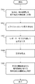
- FIG. 8A is a schematic diagram showing a fluorescence image (grayscale image) of the reference droplet
- FIG. 8B shows an image in which the fluorescence image shown in FIG. 8A is binarized by a predetermined image process to determine the fluorescence intensity.
- FIG. 8C is a schematic diagram showing a fluorescence image (grayscale image) of a droplet containing a sample and a detection reagent
- FIG. 8D is a binarization of the fluorescence image shown in FIG. 8C by a predetermined image processing.
- It is a schematic diagram which shows the image which determined the fluorescence intensity.
- the predetermined image processing has a function of binarizing a fluorescent image based on luminance information.
- the negative droplet 801 is a droplet that does not contain the target nucleic acid and does not generate fluorescence derived from the fluorescent substance possessed by the reporter molecule.
- the positive droplet 802 is a droplet containing a target nucleic acid and is a droplet that produces fluorescence derived from a fluorescent substance possessed by the reporter molecule.
- Step S206 After the trans-cleaving reaction in the incubation in step S202, the concentration of the target nucleic acid is calculated from the number of fluorescent droplets. If the sample contains a large number of target nucleic acids, one droplet may contain more than one molecule of target nucleic acid. Therefore, the number of molecules of the target nucleic acid and the number of fluorescent droplets may not match.
- the concentration of the target nucleic acid by calculation considering the Poisson distribution.
- the ratio P (k) of the droplets that generate fluorescence can be expressed by the following equation (1).
- P (k) can be obtained from the number of fluorescent droplets, and ⁇ can be calculated. Therefore, by using the formula (1), the concentration of the target nucleic acid can be calculated from the number of droplets in which fluorescence is detected among all the droplets.
- FIG. 7 is a flowchart showing the flow of the nucleic acid detection method according to the present invention when the individual independent separation compartment is a well.
- Step S301 As the well plate, the well plate 200 shown in FIGS. 2A and 2B is used.
- the well plate 200 has an injection port portion (not shown) and an discharge port portion (not shown) open, and a reaction solution composed of a sample and a detection reagent is sent from the injection port portion to the space 205.
- Step S302 The reaction solution is filled in the well 204.
- the method for filling the reaction solution include a method in which the well plate 200 is left under reduced pressure to degas the space 205. Specifically, it is preferable to leave the well plate 200 in a decompression desiccator at 0.1 atm for a predetermined time. By degassing, the air in the well 204 is removed, and the reaction solution can be efficiently filled in the well 204.
- the degassing time is not particularly limited and can be set arbitrarily.
- the filling method of the reaction solution is not limited to the degassing method.
- Step S303 A hydrophobic solvent is sent to the space 205 for sealing. That is, the reaction solution existing in the space 205 above the well 204 is replaced with a hydrophobic solvent.
- a hydrophobic solvent for example, fluorine-based oil, saturated aliphatic hydrocarbon, unsaturated aliphatic hydrocarbon, aromatic hydrocarbon, silicone oil and the like can be used.
- fluorine-based oil include Fluorinert (manufactured by 3M), Asahiclean AE-3000 (manufactured by AGC), Fomblin (manufactured by Solvay) and the like.
- the saturated hydrocarbon include isopar (manufactured by ExxonMobil) and mineral oil.
- Step S304 Incubate the well plate 200 filled with the reaction solution in an incubator at 37 ° C.
- the reaction temperature can be set arbitrarily and is not limited to 37 ° C.
- the fluorescence intensity of the well 204 is determined to identify the well 204 having a fluorescence intensity above a predetermined threshold.
- Well 204 having a fluorescence intensity above a predetermined threshold can be identified based on the ratio of the fluorescence intensity in the reference well to the fluorescence intensity in the well 204 containing the sample and the detection reagent.
- the fluorescence intensity in the reference well means the fluorescence intensity obtained for the well 204 which does not contain the target nucleic acid and contains the detection reagent.
- Predetermined image processing is used to determine the fluorescence intensity of each well 204.
- Image J as described above can be used as the image processing software, and the fluorescence intensity of each well 204 can be determined by the same operation as when the individual independent separation section is a droplet.
- Step S307 The concentration of the target nucleic acid can be calculated by the same operation as when the individual independent separation compartment is a droplet.
- the nucleic acid detection method in the present embodiment may include other steps other than the steps listed above.
- steps include a step of acquiring a reference fluorescence image (hereinafter, abbreviated as reference fluorescence image).
- reference fluorescence image a reference fluorescence image
- the fluorescence image obtained in S204 or S305 contains fluorescence derived from a substance other than the fluorescent substance for detecting nucleic acid
- the concentration of nucleic acid may not be calculated correctly.
- fluorescence derived from a fluorescent substance other than the fluorescent substance for detecting nucleic acid for example, fluorescence emitted by a well or the like can be considered.
- the timing for acquiring the reference fluorescence image in the step of acquiring the reference fluorescence image may be before the reporter molecule is cleaved by the presence of nucleic acid and fluorescence is emitted.
- the sample or detection reagent is filled into the wells or droplets, before the filling of the sealing oil that seals the individual independent compartments such as the wells or droplets, or before the incubation of S202 or S304 (heating is performed).
- the reference fluorescence image can be obtained before the test.
- the timing for acquiring the reference fluorescence image is after the detection reagent is filled in the well or the droplet and before the incubation is performed (before the heating is performed), the well or the droplet is filled with the detection reagent.
- the reference fluorescence image may be acquired after a predetermined time from the time when the operation is started. If the timing for acquiring the reference fluorescence image is before the incubation (before the heating is performed), even if the heating means that has received the drive signal acquires the reference fluorescence image before the heating operation is started. good. Further, the timing of acquiring the reference fluorescence image may be determined by using a means for monitoring the filling state of the sample or the detection reagent in the well or the droplet.
- the reference fluorescence image can be used as a reference for calculating the fluorescence intensity based on the presence of nucleic acid in each well or each droplet in the fluorescence image obtained in the steps of S204 and S305. That is, if it is calculated from the fluorescence intensity of the reference fluorescent image acquired in advance to what extent the fluorescence intensity has increased, it is derived from a component other than the fluorescent substance for detecting nucleic acid in the well or droplet. The intensity of fluorescence can be excluded. This makes it possible to more accurately obtain the fluorescence intensity derived from the fluorescent substance for detecting nucleic acid.
- this predetermined threshold value may be determined prior to determining the number of the wells or the number of droplets.
- this predetermined threshold value may be a value fixed to the nucleic acid detection device or a value set by user input. It can be said that the determination that the value is equal to or higher than the predetermined threshold value is determined to be positive, and the determination that the value is lower than the predetermined threshold value is determined to be negative.
- a reference fluorescence image may be acquired in order to detect a state in which the sample to be filled or the detection reagent is not filled due to, for example, a well, a droplet, or a defect in the filling operation thereof.
- a substance that emits light having a wavelength different from that of the fluorescent substance used for detecting nucleic acid hereinafter referred to as a reference substance
- a fluorescent image is acquired, and a fluorescence distribution is acquired. You may.
- the difference between the center wavelength of the emission wavelength (fluorescence wavelength) of the reference substance and the center wavelength of the emission wavelength (fluorescence wavelength) of the fluorescent substance used for detecting the nucleic acid is preferably 30 nm or more, preferably 50 nm or more. It is more preferable that the wavelength is 100 nm or more, and it is further preferable that the wavelength is 100 nm or more. If fluorescence is not detected as a result of acquiring the reference fluorescence image, the process may be restarted from the first step, an error may be displayed, or the fluorescence may be restarted according to the number of wells or droplets in which fluorescence is not detected. It may be decided whether to continue the measurement or to continue the measurement.
- this predetermined threshold value may be determined prior to determining the number of the wells or the number of droplets.
- this predetermined threshold value may be a value fixed to the nucleic acid detection device or a value set by user input.
- the user may be able to appropriately select the operation when fluorescence is not detected as a result of acquiring the reference fluorescence image. ..
- the mode having the above-mentioned step of acquiring the reference fluorescence image and the mode not having the step of acquiring the reference fluorescence image can be switched. good.
- the step of acquiring the reference fluorescence image has been described in the nucleic acid detection method according to the present embodiment, but it can also be applied to the nucleic acid detection apparatus according to the present embodiment.
- the reference fluorescence image may be acquired by using the fluorescence detection unit or the image acquisition unit in the nucleic acid detection device according to the present embodiment, or the reference fluorescence image may be acquired by other means (for example, the reference fluorescence image acquisition unit). You may get it.
- the program according to the present invention is a program for causing a computer included in the nucleic acid detection device to execute the nucleic acid detection method described above in order to cause the nucleic acid detection device to execute the method.
- Example 1 (Preparation of reagents) -Preparation of Cas12a stock solution (400 nM) EnGen LbaCas12a (Cpf1) (trade name: M0653T, manufactured by NEB, 100 ⁇ M) (hereinafter, simply referred to as Cas12a) was used as Cas12a.
- Cas12a was diluted with nucleicase free water (trade name: B1500S, manufactured by NEB) (hereinafter, simply referred to as purified water) to prepare a Cas12a stock solution (400 nM).
- crRNA undiluted solution of crRNA (500 nM) Lb.
- Cas12a-crRNA1 custom product, manufactured by SIGMA, 100 ⁇ M
- the crRNA was diluted with purified water to prepare a crRNA stock solution (500 nM).
- the base sequence of crRNA is shown below (SEQ ID NO: 1). uaauuucuacuaaguguagaugucuggccuuaauccaugcc
- DNA_113bp -Preparation of DNA solution Synthetic DNA (hereinafter referred to as DNA_113bp) was used as the target nucleic acid.
- DNA_113bp was diluted with purified water to prepare a DNA stock solution (4 nM), and the concentration was measured and confirmed with a Qubit 2.0 Fluorometer (manufactured by Life Technologies).
- the DNA stock solution (4 nM) was diluted with purified water to prepare a DNA solution (0.684 nM) (final concentration 0.171 nM). Further, the DNA solution (0.684 nM) was serially diluted 1/3 with purified water to prepare DNA solution 1 (0.228 nM), DNA solution 2 (0.076 nM), and DNA solution 3 (0.025 nM). ..
- DNA_113bp The base sequence of DNA_113bp is shown below (SEQ ID NO: 2). ctcacgccttatgactgcccttatgtcaccgcttatgtctcccgatatcacacccgttatctcagccctaatctctgcggtttagtctggccttaatccatgcctcatagcta
- reporter molecule solution (12 ⁇ M)
- the reporter molecule contained in a commercially available kit (trade name: DNaseAlert (registered trademark) Substrate Nuclease Detection System 11-02-01-04, manufactured by IDT) was used.
- This reporter molecule has a fluorescent substance, HEX, and a quencher.
- HiLyte (registered trademark) Fluor488 (AnaSpec) used as a standard fluorescent substance for confirming droplets described later was dissolved in purified water to prepare a standard fluorescent substance solution (800 nM).
- the reporter molecule is contained in 50 pmol for each reporter molecule-containing tube included in the above kit.
- 12 reporter molecules were dissolved in 50 ⁇ L of a standard fluorescent substance solution (800 nM). This prepared a reporter molecular solution (12 ⁇ M).
- Samples 1 to 4 for forming droplets as individual independent compartments were prepared. Specifically, first, Cas12a stock solution (400 nM): 20 ⁇ L, crRNA stock solution (500 nM): 20 ⁇ L, and 1 to 3: 40 ⁇ L of the DNA solutions of each concentration prepared above were mixed. Here, in the preparation of sample 1, purified water was used instead of the DNA solution. The resulting mixed solution was reacted at 37 ° C. for 30 minutes to induce the formation of Cas12a-crRNA-DNA complex.
- the concentrations of the components other than DNA contained in the droplet-forming samples 1 to 4 are Cas12a: 50 nM, crRNA: 62.5 nM, reporter molecule: 3 ⁇ M, and HiLyte 488: 200 nM, respectively.
- Dispersed phase Samples 1 to 480 ⁇ L for each droplet formation
- Continuous phase 2.5 mL of aliphatic hydrocarbon (trade name: IsoparL, manufactured by ExxonMobil) in which a surfactant (trade name: KF-6038, manufactured by Shin-Etsu Chemical Co., Ltd.) is dissolved at a concentration of 4%.
- aliphatic hydrocarbon trade name: IsoparL, manufactured by ExxonMobil
- a surfactant trade name: KF-6038, manufactured by Shin-Etsu Chemical Co., Ltd.
- an SPG pumping connector (hole diameter 20 ⁇ m, manufactured by SPG Techno Co., Ltd.) was used, and the number of pumping times was 10. As a result, a droplet having a diameter of about 5 ⁇ m (volume of about 65 fL) was obtained.
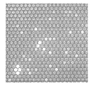
- 9A-9D are diagrams showing fluorescence microscope images obtained after reacting droplets prepared using each sample for 6 hours.
- 9A shows sample 1
- FIG. 9B shows sample 2
- FIG. 9C shows sample 3
- FIG. 9D shows fluorescence microscope images obtained for sample 4, respectively.
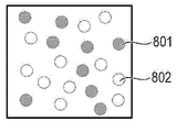
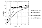
- FIGS. 10A to 13B are diagrams showing changes in the fluorescence of droplets with time for Samples 1 to 4, respectively.
- 10A, 11A, 12A, and 13A show fluorescence microscopic images containing both the fluorescence of HEX derived from the reporter molecule and the background fluorescence of the reporter molecule, respectively.
- FIGS. 10B, 11B, 12B, and 13B show fluorescence microscope images containing fluorescence of a standard fluorescent substance, respectively.
- droplets could be confirmed based on the fluorescence of the standard fluorescent substance. Further, as shown in FIGS. 11A, 11B, 12A, 12B, and 13A, 13B, it can be seen that the fluorescence of the standard fluorescent substance is also observed in the droplets in which the fluorescence of HEX is observed. From this, it was confirmed that the sample and the detection reagent were filled in the droplet, and the trans-cleaving reaction of Cas12a worked.
- FIGS. 9A to 13B it was confirmed that the number of positive droplets increased as the DNA concentration increased.
- FIG. 51 described in Patent Document 1 it has been difficult to detect a target nucleic acid having a low concentration of 6.3 pM by the CHRISPR-Cas technique without going through an amplification step in the prior art. From the results of the above examples, it was shown that in the present invention, the target nucleic acid having a concentration of 6.3 pM can be detected without going through the amplification step.
- the fluorescence intensity of each droplet was determined, and the droplet having the fluorescence intensity exceeding a predetermined threshold was identified.
- the droplet obtained for Sample 1 is used as a reference droplet, and the droplet having a fluorescence intensity exceeding a predetermined threshold is used as the ratio of the fluorescence intensity of the reference droplet to the fluorescence intensity of the sample and the droplet containing the detection reagent. Identified based on.
- the fluorescence intensity of the droplet containing the sample and the detection reagent is the fluorescence intensity of each droplet obtained for Samples 2 to 4.
- a predetermined image processing image processing software was used to determine the fluorescence intensity of each droplet.
- the fluorescence intensity of each droplet (negative droplet) obtained for Sample 1 6 hours after the reaction was 100.
- the fluorescence intensity of the positive droplets in each of the droplets obtained for Samples 2 to 4 6 hours after the reaction was in the range of 200 to 250.
- the concentration of the target nucleic acid can be calculated from the total number of droplets and the number of droplets having a fluorescence intensity exceeding a predetermined threshold value.
- Example 2 (Making wells)
- the wells 204 shown in FIGS. 2A and 2B were produced through a CYTOP coating step, a photolithography step, and an etching / resist removing step.
- a quartz substrate synthetic quartz substrate AQ grade, thickness 1 mm, manufactured by AGC
- KBE-903 silane coupling agent
- CTL-809A manufactured by AGC
- positive photoresists AZ P4903, AZ Electrical Materials
- UV was exposed from above via a photomask of a target pattern, and development treatment was performed with alkali.
- the photoresist was dissolved only in the portion irradiated with UV, and the hydrophobic resin layer was exposed.
- the etching / resist removing step a part of the resin layer was removed by etching with oxygen plasma via a photoresist in which a part was dissolved to form a hydrophobic partition wall.
- the desired well 204 was formed by dissolving the photoresist in an organic solvent.
- the diameter of the well 204 was 5 ⁇ m, the depth was 4 ⁇ m, the pitch was 10 ⁇ m, and the number of wells was about 1 million.
- the well plate 200 shown in FIGS. 2A and 2B includes a lower substrate 201 on which the above-mentioned well 204 is formed, an upper substrate 202, an injection port portion (not shown), and a discharge port portion (not shown).
- a lower substrate 201 on which the above-mentioned well 204 is formed
- an upper substrate 202 on which the above-mentioned well 204 is formed
- an injection port portion not shown
- a discharge port portion not shown.
- Polycarbonate thickness 1 mm
- the distance of the space 205 from the upper surface of the partition wall 203 to the upper substrate 202 was 250 ⁇ m.
- the reaction solution was injected from the injection port portion on the upper substrate 202, and the reaction solution was sent so as to cover the well 204.
- the well plate 200 was left under reduced pressure, the space 205 was degassed, and the well was filled with the reaction solution.
- a hydrophobic solvent was sent to the space 205 and sealed.
- asahiclean AE-3000 manufactured by AGC
- von Bryn Y-25 manufactured by Solvay
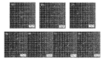
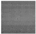
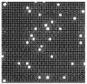
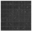
- FIG. 14A-14D are diagrams showing fluorescence microscope images of wells.
- FIG. 14A shows a fluorescence microscope image containing both the fluorescence of HEX derived from the reporter molecule and the background fluorescence of the reporter molecule 2 hours after the reaction.
- FIG. 14B shows a fluorescence microscope image containing fluorescence of a standard fluorescent substance 2 hours after the reaction.
- FIG. 14C shows a fluorescence microscope image including both the fluorescence of HEX derived from the reporter molecule and the background fluorescence of the reporter molecule 19 hours after the reaction.
- FIG. 14D shows a fluorescence microscope image containing fluorescence of a standard fluorescent substance 19 hours after the reaction.
- FIGS. 14B and 14D wells could be identified based on the fluorescence of the standard fluorescent material. Further, as shown in FIGS. 14A to 14D, it can be seen that the fluorescence of the standard fluorescent substance is also observed in the wells in which the fluorescence of HEX was observed. From this, it was confirmed that the well was filled with the sample and the detection reagent, and the trans-cleaving reaction of Cas12a worked. Further, as shown in FIG. 51 described in Patent Document 1, it has been difficult to detect a target nucleic acid having a low concentration of 6.3 pM by the CHRISPR-Cas technique without going through an amplification step in the prior art. From the results of the above examples, it was shown that in the present invention, the target nucleic acid having a concentration of 6.3 pM can be detected without going through the amplification step.
- predetermined image processing was performed on the fluorescence microscope image 19 hours after the reaction of the above-mentioned example to obtain the histogram shown in FIG.
- the histogram shown in FIG. 15 shows the number of wells showing the fluorescence intensity contained in each fraction of the fluorescence intensity obtained by dividing the fluorescence intensity by a constant value.
- three peaks A, B, and C corresponding to the division in which the count number showed the maximum value were observed.
- the lowest fluorescence intensity peak A is due to the background fluorescence of the reporter molecule.
- the wells in the peak B category were identified as positive wells B
- the wells in the peak C category were identified as positive wells C.
- the fluorescence intensity of the positive well C is stronger, so that the positive well B is filled with one DNA in one well. It is considered that the positive well C is filled with two DNAs in one well.
- the concentration of the target nucleic acid can be calculated from the total number of wells and the number of positive wells specified from the histogram using the above formula (1).
- Example 3 (Preparation of reaction solution for wells) A reaction solution was prepared for filling well 204. Specifically, first, Cas12a stock solution (400 nM): 20 ⁇ L, crRNA stock solution (500 nM): 20 ⁇ L, and DNA solution 1 (0.228 ⁇ M): 40 ⁇ L were mixed. The resulting mixed solution was reacted at 37 ° C. for 30 minutes to induce the formation of Cas12a-crRNA-DNA complex.
- a reporter molecular solution (12 ⁇ M) containing 800 nM HiLyte488: 25 ⁇ L, Tween20 (5%): 10 ⁇ L, BSA (30%): 1 ⁇ L, spermine aqueous solution (50 mM): 4 ⁇ L, 10 ⁇ Binding buffer: 10 ⁇ L were prepared in advance. Mixed in 1.5 mL microtubes. To this mixed solution, 50 ⁇ L of the solution mixed and reacted above was added to prepare a reaction solution for wells. The final concentration of DNA was 57 pM.
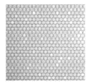
- FIGS. 16A and 16B are diagrams showing fluorescence microscope images obtained after reacting for 0.5 hours.
- FIG. 16A shows a fluorescence microscope image containing both the fluorescence of HEX derived from the reporter molecule and the background fluorescence of the reporter molecule.
- FIG. 16B shows a fluorescence microscope image including fluorescence of a standard fluorescent substance. As shown in FIG. 16B, wells could be identified based on the fluorescence of the standard fluorescent material. Further, as shown in FIGS. 16A and 16B, it can be seen that in the wells where the fluorescence of HEX was observed, the fluorescence of the standard fluorescent substance was also observed.
- Example 3 using the reaction solution containing spermine, the fluorescence of HEX could be observed in 0.5 hours.
- the fluorescence of HEX could not be confirmed after 0.5 hours. From this, it was confirmed that the inclusion of spermine in the detection reagent promoted the trans-cleaving reaction of Cas12a, and the detection time could be shortened as compared with Example 2 using the detection reagent containing no amino compound.
- Example 4 Preparation of composite particles in which the complex of Cas12a and crRNA is bound to the particles.
- a magnetic particle (Magnosphere (registered trademark) MS300 / Carboxyl) dispersion was placed in a microtube to precipitate the magnetic particles with a magnet.
- MES buffer 100 mM, pH 5.4
- N-hydroxysulfosuccinimide sulfo-NHS
- WSC water-soluble carbodiimide
- the recovered magnetic particles were washed with MES buffer, dispersed with MES buffer, and an arbitrary amount of anti-His tag antibody (Anti-His-tag mAb, MBL Life Science) was added. Then, the mixture was stirred at 25 ° C. for 2 hours. Subsequently, a large excess of ethanolamine was added to deactivate the active groups on the surface of the magnetic particles. The magnetic particles were recovered with a magnet, and the recovered magnetic particles were washed with MES buffer to prepare antibody-immobilized particles.
- a storage buffer (10 mM HEPES-NaOH (pH 7.9), 50 mM KCl, 1 mM EDTA, 10% glycerol) was added to the obtained antibody-immobilized particles to prepare an antibody-immobilized particle solution.
- the antibody-immobilized particle solution was stored at 4 ° C. until use.
- diluted Cas12a and crRNA were mixed to a concentration ratio (molar ratio) of 1: 1.25 and incubated at 37 ° C. for 30 minutes to prepare a Cas12a-crRNA complex.
- the prepared antibody-immobilized particle solution (1 wt%) was separated into a 2 mL sample tube (manufactured by VIOLAMO, model number: 1-1600-04). After stirring, a sample tube was placed on a magnetic stand (magical trapper, manufactured by TOYOBO, model number: MGS-101), allowed to stand for 1 minute, and then the supernatant was removed to remove the solution. PBS (PBS-T) containing 0.05% Tween 20 was added as a particle washing solution, and after stirring, the solution was removed in the same manner as above. The above operation was repeated twice for cleaning.
- the washed antibody-immobilized particles were suspended in PBS-T, the Cas12a-crRNA solution prepared above was added to an arbitrary concentration, and the mixture was stirred and then reacted with a shaker for 1 hour.
- the Cas12a used has a His tag at the N-terminal
- Cas12a and the antibody-immobilized particles are bound by an antigen-antibody reaction between the His tag possessed by Cas12 and the anti-His-tag antibody possessed by the antibody-immobilized particles.
- a composite particle in which the complex of Cas12a and crRNA was bound to the particle was prepared. After the reaction, the solution was removed and a washing operation was performed with PBS-T. After washing, it was suspended in purified water, stirred, and stored at 4 ° C. until use.
- reaction solution for filling well 204. Specifically, first, the composite particles (3.1 ⁇ 10 8 pieces / mL) prepared above: 7.3 ⁇ L, water: 22.7 ⁇ L, and DNA solution 1 (0.228 ⁇ M): 30 ⁇ L were mixed. The obtained mixed solution was reacted at 37 ° C. for 30 minutes to form a complex of composite particles and DNA. Next, the following materials were prepared.
- FIG. 17A to 17C are views showing a bright-field image and a fluorescence microscope image of wells acquired after reacting for 1 hour.
- FIG. 17A shows a brightfield image of the well.
- FIG. 17B shows a fluorescence microscope image containing both the fluorescence of HEX derived from the reporter molecule and the background fluorescence of the reporter molecule.
- FIG. 17C shows a fluorescence microscope image including fluorescence of a standard fluorescent substance. From FIG. 17A, it was confirmed that the wells were filled with particles. Further, from FIGS. 17A to 17C, it can be seen that the fluorescence of HEX is observed from the well filled with the particles. From this, it was confirmed that the DNA was captured by Cas12a bound to the particles and the trans-cleaving reaction of Cas12a worked.
- the DNA concentration of 57 pM in this example is a concentration predicted to be positive for all individual independent separation compartments.
- Example 5 (Immobilization of anti-His tag antibody on magnetic particles) A dispersion of magnetic particles (Magnosphere® MS300 / Carboxyl) was placed in a microtube to precipitate the magnetic particles with a magnet. After removing the supernatant, MES buffer (100 mM, pH 5.4) was added to the magnetic particle pellets and dispersed again, and N-hydroxysulfosuccinimide (sulfo-NHS) and water-soluble carbodiimide (WSC) were added. .. The mixture was stirred at 25 ° C. for 1 hour, and the magnetic particles were collected with a magnet.
- MES buffer 100 mM, pH 5.4
- the recovered magnetic particles were washed with MES buffer, dispersed with MES buffer, and an arbitrary amount of anti-His tag antibody (Anti-His-tag mAb, MBL Life Science) was added.
- the mixture was stirred at 25 ° C. for 2 hours.
- two methods were prepared, one in which the blocking operation was performed and the other in which the blocking operation was not performed.
- a large excess of PEGamine having a molecular weight of 5000 was added to the carboxy group on the surface of the magnetic particles, and the mixture was stirred at room temperature for 45 minutes. With or without blocking, a large excess of ethanolamine was subsequently added to deactivate the active groups on the particle surface.
- Magnetic particles were recovered with a magnet, and the recovered magnetic particles were washed with MES buffer to prepare antibody-immobilized particles (with and without blocking).
- a storage buffer (10 mM HEPES-NaOH (pH 7.9), 50 mM KCl, 1 mM EDTA, 10% glycerol) was added to the antibody-immobilized particles to prepare an antibody-immobilized particle solution, which was stored at 4 ° C. until use.
- the above operation was repeated twice.
- the particles were suspended in PBS-T, the Cas12a-crRNA solution prepared above was added to an arbitrary concentration, and the mixture was stirred and then reacted with a shaker for 1 hour. After the reaction, the solution was removed and a washing operation was performed with PBS-T. After washing, the particles were suspended in purified water to prepare composite particles in which the Cas12a-crRNA complex was bound to the antibody-immobilized particles. After stirring, it was stored at 4 ° C. until use.
- composite particles AntBL those that have undergone the blocking operation
- composite particles Ant those that have not undergone the blocking operation
- PBS-T was added as a particle washing solution, and the solution was removed after stirring. The above operation was repeated twice.
- the particles were suspended in PBS-T, the Cas12a solution prepared above was added to an arbitrary concentration, and the mixture was stirred and then reacted with a shaker for 1 hour. After the reaction, the solution was removed and a washing operation was performed with PBS-T. After washing, the particles were suspended in purified water to prepare composite particles in which the Cas12a-crRNA complex was immobilized on nickel particles. After stirring, it was stored at 4 ° C. until use. The obtained composite particles were designated as composite particles Ni.
- a 96-well plate (Thermo Fisher Scientific, model number: 137101) was used to evaluate the activity of the composite particles prepared above under the conditions with and without the addition of the amino compound. Mix each particle in water so that the final concentration of Cas12a is 10 nM, and the final concentration of DNA is 2 nM, and let stand at 37 ° C. for 30 minutes or more to form a complex with DNA. Made.
- reaction buffer two methods were performed: a case where a binding buffer was used and a case where NE Buffer (registered trademark) was used. Then, with a fluorescent plate reader (Synergy MX, manufactured by BioTek), the fluorescence intensity was measured at 37 ° C. for 2 hours every 2 min.
- HiLyte488 used an excitation wavelength of 485 ⁇ 20 nm and a fluorescence wavelength of 528 ⁇ 20 nm.
- reporter molecule an excitation wavelength of 535 ⁇ 20 nm and a fluorescence wavelength of 595 ⁇ 20 nm were used.
- NEBuffer® 2.1 was used by adding 10 ⁇ NEBuffer® 2.1 attached to EnGen LbaCas12a (Cpf1) (NEB, M0653T) in an amount of 1/10 of the reaction solution. ..
- the obtained fluorescence intensity was evaluated as the ratio of the fluorescence intensity of the reporter molecule to the fluorescence intensity of the internal standard dye (fluorescence intensity of the reporter molecule / fluorescence intensity of the internal standard dye).
- FIGS. 18A to 18C show changes over time in the fluorescence intensity ratio (fluorescence intensity of the reporter molecule / fluorescence intensity of the internal standard dye) when each composite particle is used.
- FIG. 18A shows the result when the composite particle Ant is used
- FIG. 18B shows the result when the composite particle AntBL is used
- FIG. 18C shows the result when the composite particle Ni is used.
- FIGS. 18A to 18C it can be seen that the reaction was promoted by adding spermine, which is an amino compound, regardless of which composite particle or reaction buffer was used.
- crRNA_T790M The crRNA included in EnGen LbaCas12a (Cpf1) (NEW ENGLAND BioLabs (NEB), M0653T) was diluted with purified water to prepare a storage solution of 500 nM.
- the sequence of crRNA_T790M is shown below (SEQ ID NO: 3). uaauuucuacuaaguguagauaucaugcagcucaugccc
- the sample tube was placed on a magnetic stand (manufactured by Magical Trapper TOYOBO, model number: MGS-101), allowed to stand for 1 minute, and the supernatant was removed to remove the solution.
- PBS containing 0.5% Tween 20 was added as a particle washing solution, and the solution was removed after stirring. The above operation was repeated twice.
- the particles were suspended in PBS containing 0.5% Tween20, the Cas12a-crRNA complex prepared above was added to an arbitrary concentration, and the mixture was stirred and then reacted with a shaker for 1 hour. After the reaction, the solution was removed and a washing operation was performed with purified water. After washing, it was suspended in purified water to prepare composite particles. After stirring, it was stored at 4 ° C. until use.
- Genomic DNA 100% EGFR wild type (50 ng / ⁇ L, RIKEN GENESIS, model number: HD709) and 50% EGFR T790M (50 ng / ⁇ L, RIKEN GENESIS, model number: HD258) were used as templates in PCR, respectively.
- the product amplified by PCR using 100% EGFR wild type as a template was designated as contaminating DNA_WT.
- the product amplified by PCR using 50% EGFR T790M as a template was used as the target DNA_T790M.
- concentrations of all PCR products were measured with a Qubit 2.0 Fluorometer (manufactured by Life Technologies).
- the subsequent concentrations of the PCR amplification product using 50% EGFR T790M as a template were calculated on the assumption that the mutant allele ratio was the same as that of 50% EGFR T790M.
- Each PCR product was diluted with purified water to prepare a 4 nM storage solution. Further, a 4 nM storage solution was diluted with purified water to prepare DNA solutions having various concentrations.
- EGFR primer (Forward) (SEQ ID NO: 4)
- tcacctccaccgtgcatttcatca EGFR primer (Reverse) (SEQ ID NO: 5)
- DNA_WT (SEQ ID NO: 6) tcacctccaccgtgcatttcatcacgcagctcatgcccttcggctgcctcctggactatgtccgggaacacaaagacaatattggctcccagtacctgctcaactggtgtgtgcagatcgcaa
- DNA_T790M (SEQ ID NO: 7) tcacctccaccgtgcatttc atcatgcagctcatgccc cttcggctgcctctggactatgtccgggaacacaaagacaatattggctcccagtacctgctcaactggtgtgtgcagatcgcaa
- the efficiency of collecting and concentrating DNA was evaluated for the composite particles prepared above.
- the following materials were prepared. -The number of immobilized Cas12a is 6.7 x 10 5 / particle composite particles (referred to as composite particles A): 2.7 x 10⁻¹¹ mol. -The number of immobilized Cas12a is 1.5 x 10 4 / particle composite particles (referred to as composite particles B): 6.0 x 10⁻¹³ mol.
- -Target DNA_T790M 1.5 x 10⁻¹³ mol -DNA_WT as contaminated DNA: 1.5 ⁇ 10-12 mol ⁇ Tween20: Final concentration 0.5%
- Composite particles A or B and target DNA_T790M, DNA_WT, and Tween20 were added to a 2 mL tube (Eppendorf) to prepare a total solution volume of 1.1 mL. The resulting mixed solution was shaken at room temperature for 1 hour. Then, the particles were collected with a magnet, the supernatant was removed, and the particles were washed with 1 mL of purified water.
- the particles were collected again with a magnet, the supernatant was removed, and the particles were suspended in 50 ⁇ L of purified water to obtain a DNA-recovered particle solution. Further, in the above, assuming that the contaminated DNA is not contained, the same operation was performed without using DNA_WT.
- DNA recovery particle solution final concentration of composite particles: 4 ⁇ 10-13 M
- -Reporter molecule final concentration: 125 nM
- 8nM HiLyte488 as an internal standard dye 2 mM spermine
- the measurement wavelength used was an excitation wavelength of 485 ⁇ 20 nm and a fluorescence wavelength of 528 ⁇ 20 nm.
- the reporter molecule an excitation wavelength of 535 ⁇ 20 nm and a fluorescence wavelength of 595 ⁇ 20 nm were used.
- the target DNA_T790M was added without performing the recovery operation, and the fluorescence intensity was measured in the same manner as above.
- the composite particles A or B have the same molar concentration as above (final concentration of composite particles: 4 ⁇ 10-13 M), and the final concentration of 1.5 nM assumed when 100% of the target DNA_T790M can be recovered. And said.
- a reporter molecule final concentration: 125 nM
- the fluorescence intensity was measured in the same manner as above.
- the obtained fluorescence intensity was evaluated as the ratio of the fluorescence intensity of the reporter molecule to the fluorescence intensity of the internal standard dye (fluorescence intensity of the reporter molecule / fluorescence intensity of the internal standard dye).
- FIG. 19A shows the change over time in the fluorescence intensity ratio when the recovery operation was performed under the condition of no contaminated DNA and when the recovery operation was not performed.
- FIG. 19B shows the time course of the fluorescence intensity ratio when the recovery operation was performed under the condition with and without the contaminated DNA.
- FIG. 19A it was confirmed that DNA could be recovered and concentrated with a high recovery rate regardless of which composite particle was used. It was also suggested that the higher the number of immobilized composite particles, the higher the recovery rate. Further, as shown in FIG. 19B, even when contaminated DNA coexists, the composite particles can recover and concentrate the DNA, and the larger the number of immobilized composite particles, the higher the recovery rate of the DNA. was confirmed.
- the trans-cleaving reaction of the effector protein is promoted and the detection time can be shortened by containing the amino compound in the detection reagent.
- the target nucleic acid can be recovered by acting on the composite particle in which the complex of the effector protein and crRNA is bound to the particle. Shown.
- the recovered target nucleic acid can be detected by filling the individual independent separation compartment with the composite particles that have captured the target nucleic acid.
- An embodiment of the invention is performed by a computer in a system or device (eg, a specific application integrated circuit (ASIC)) that reads and executes computer executable instructions (eg, one or more programs) recorded on a storage medium.
- a computer in a system or device eg, a specific application integrated circuit (ASIC)
- ASIC application integrated circuit
- a computer can include one or more processors (eg, central processing unit (CPU), microprocessing unit (MPU)), a separate computer or a separate processor to read and execute computer executable instructions.
- processors eg, central processing unit (CPU), microprocessing unit (MPU)
- Network can be included.
- Computer-executable instructions may be provided to the computer, for example, from a network or storage medium.
- Storage media include, for example, hard disks, random access memory (RAM), read-only memory (ROM), storage devices for distributed computing systems, optical discs (compact discs (CDs), digital versatile discs (DVDs), and Blu-ray discs (BDs). ) Etc.), may include one or more of flash memory devices, memory cards, etc.
Landscapes
- Chemical & Material Sciences (AREA)
- Health & Medical Sciences (AREA)
- Life Sciences & Earth Sciences (AREA)
- Engineering & Computer Science (AREA)
- Organic Chemistry (AREA)
- Zoology (AREA)
- Wood Science & Technology (AREA)
- Bioinformatics & Cheminformatics (AREA)
- Genetics & Genomics (AREA)
- General Health & Medical Sciences (AREA)
- Biochemistry (AREA)
- Biotechnology (AREA)
- Molecular Biology (AREA)
- General Engineering & Computer Science (AREA)
- Analytical Chemistry (AREA)
- Physics & Mathematics (AREA)
- Microbiology (AREA)
- Immunology (AREA)
- Proteomics, Peptides & Aminoacids (AREA)
- Biomedical Technology (AREA)
- Biophysics (AREA)
- Medicinal Chemistry (AREA)
- General Physics & Mathematics (AREA)
- Chemical Kinetics & Catalysis (AREA)
- Nuclear Medicine, Radiotherapy & Molecular Imaging (AREA)
- Pathology (AREA)
- Sustainable Development (AREA)
- Plant Pathology (AREA)
- Optics & Photonics (AREA)
- Measuring Or Testing Involving Enzymes Or Micro-Organisms (AREA)
- Apparatus Associated With Microorganisms And Enzymes (AREA)
Priority Applications (3)
| Application Number | Priority Date | Filing Date | Title |
|---|---|---|---|
| CN202180069220.8A CN116391023A (zh) | 2020-10-13 | 2021-10-12 | 核酸检测装置及检测核酸的方法 |
| JP2022556986A JP7813716B2 (ja) | 2020-10-13 | 2021-10-12 | 核酸検出装置および核酸の検出方法 |
| US18/295,976 US20230295689A1 (en) | 2020-10-13 | 2023-04-05 | Nucleic acid detection apparatus and method of detecting nucleic acid |
Applications Claiming Priority (4)
| Application Number | Priority Date | Filing Date | Title |
|---|---|---|---|
| JP2020-172561 | 2020-10-13 | ||
| JP2020172561 | 2020-10-13 | ||
| JP2021091877 | 2021-05-31 | ||
| JP2021-091877 | 2021-05-31 |
Related Child Applications (1)
| Application Number | Title | Priority Date | Filing Date |
|---|---|---|---|
| US18/295,976 Continuation US20230295689A1 (en) | 2020-10-13 | 2023-04-05 | Nucleic acid detection apparatus and method of detecting nucleic acid |
Publications (1)
| Publication Number | Publication Date |
|---|---|
| WO2022080343A1 true WO2022080343A1 (ja) | 2022-04-21 |
Family
ID=81208209
Family Applications (1)
| Application Number | Title | Priority Date | Filing Date |
|---|---|---|---|
| PCT/JP2021/037659 Ceased WO2022080343A1 (ja) | 2020-10-13 | 2021-10-12 | 核酸検出装置および核酸の検出方法 |
Country Status (4)
| Country | Link |
|---|---|
| US (1) | US20230295689A1 (https=) |
| JP (1) | JP7813716B2 (https=) |
| CN (1) | CN116391023A (https=) |
| WO (1) | WO2022080343A1 (https=) |
Cited By (2)
| Publication number | Priority date | Publication date | Assignee | Title |
|---|---|---|---|---|
| CN114875179A (zh) * | 2022-05-24 | 2022-08-09 | 深圳谱尼医学检验实验室 | 一种高精度病毒检测方法、系统、计算机设备及存储介质 |
| WO2022210822A1 (ja) * | 2021-04-02 | 2022-10-06 | キヤノン株式会社 | 試薬、及びそれを用いた標的核酸の検出方法 |
Families Citing this family (2)
| Publication number | Priority date | Publication date | Assignee | Title |
|---|---|---|---|---|
| TWI881473B (zh) * | 2023-09-22 | 2025-04-21 | 台達電子工業股份有限公司 | 核酸檢測裝置 |
| JP2026001306A (ja) * | 2024-06-19 | 2026-01-07 | キヤノン株式会社 | 充填方法及び充填システム |
Citations (2)
| Publication number | Priority date | Publication date | Assignee | Title |
|---|---|---|---|---|
| WO2019148206A1 (en) * | 2018-01-29 | 2019-08-01 | The Broad Institute, Inc. | Crispr effector system based diagnostics |
| EP3653722A1 (en) * | 2017-07-14 | 2020-05-20 | Shanghai Tolo Biotechnology Company Limited | Application of cas protein, method for detecting target nucleic acid molecule and kit |
Family Cites Families (1)
| Publication number | Priority date | Publication date | Assignee | Title |
|---|---|---|---|---|
| US10253365B1 (en) * | 2017-11-22 | 2019-04-09 | The Regents Of The University Of California | Type V CRISPR/Cas effector proteins for cleaving ssDNAs and detecting target DNAs |
-
2021
- 2021-10-12 CN CN202180069220.8A patent/CN116391023A/zh active Pending
- 2021-10-12 WO PCT/JP2021/037659 patent/WO2022080343A1/ja not_active Ceased
- 2021-10-12 JP JP2022556986A patent/JP7813716B2/ja active Active
-
2023
- 2023-04-05 US US18/295,976 patent/US20230295689A1/en active Pending
Patent Citations (2)
| Publication number | Priority date | Publication date | Assignee | Title |
|---|---|---|---|---|
| EP3653722A1 (en) * | 2017-07-14 | 2020-05-20 | Shanghai Tolo Biotechnology Company Limited | Application of cas protein, method for detecting target nucleic acid molecule and kit |
| WO2019148206A1 (en) * | 2018-01-29 | 2019-08-01 | The Broad Institute, Inc. | Crispr effector system based diagnostics |
Cited By (2)
| Publication number | Priority date | Publication date | Assignee | Title |
|---|---|---|---|---|
| WO2022210822A1 (ja) * | 2021-04-02 | 2022-10-06 | キヤノン株式会社 | 試薬、及びそれを用いた標的核酸の検出方法 |
| CN114875179A (zh) * | 2022-05-24 | 2022-08-09 | 深圳谱尼医学检验实验室 | 一种高精度病毒检测方法、系统、计算机设备及存储介质 |
Also Published As
| Publication number | Publication date |
|---|---|
| CN116391023A (zh) | 2023-07-04 |
| JPWO2022080343A1 (https=) | 2022-04-21 |
| US20230295689A1 (en) | 2023-09-21 |
| JP7813716B2 (ja) | 2026-02-13 |
Similar Documents
| Publication | Publication Date | Title |
|---|---|---|
| JP7813716B2 (ja) | 核酸検出装置および核酸の検出方法 | |
| Roh et al. | CRISPR‐enhanced hydrogel microparticles for multiplexed detection of nucleic acids | |
| Park et al. | Spatial transcriptomics: technical aspects of recent developments and their applications in neuroscience and cancer research | |
| US20220333192A1 (en) | Methods and devices for spatial assessment of rna quality | |
| KR102941113B1 (ko) | 샘플 처리 및 검출 동안의 제어된 환경을 위한 장벽 구현 | |
| US12421541B2 (en) | Multiomic analysis device and methods of use thereof | |
| KR20200105497A (ko) | 단백질 식별을 위한 디코딩 접근법 | |
| CN110249082A (zh) | 测定蛋白质的方法 | |
| CN118240918A (zh) | 采用微流控装置的空间编码生物分析 | |
| US20250262618A1 (en) | Implementing barriers for controlled environments during sample processing and detection | |
| US20240118274A1 (en) | Structure and methods for detection of sample analytes | |
| EP4630816A1 (en) | A method comprising performing on a single-analyte array at least 50 cycles of a process | |
| CN121294617A (zh) | 新型细胞表型筛选方法 | |
| JP4803125B2 (ja) | ビーズ群と該ビーズ群の作製方法、並びにビーズ群を用いる方法 | |
| JPWO2012026541A1 (ja) | タンパク質又はペプチドのプリンティング方法、及び、タンパク質アレイ又はペプチドアレイ、並びに、機能性タンパク質又は機能性ペプチドの同定方法 | |
| WO2024085132A1 (ja) | 生体物質処理方法及び反応検出方法並びに生体物質処理装置及び反応検出装置 | |
| Yao et al. | Hydrogel-Based Microdroplet Ensembles Encapsulating Multiplexed EXPAR Assays for Trichromic Digital Profiling of MicroRNAs and in-Depth Classification of Primary Urethral Cancers | |
| Mao et al. | Digital Quantification and Ultrasensitive Detection of Single Influenza Virus Using Microgel-in-Droplet Enzyme-Linked Immunosorbent Assay | |
| WO2022182643A1 (en) | Structure and methods for detection of sample analytes | |
| US20250377354A1 (en) | Analyte characterization by differential binding of binding reagents | |
| US20250235843A1 (en) | Microspheroids containing distinguishable microparticle patterns | |
| US20240026424A1 (en) | Reagent and method for detecting target nucleic acid using same | |
| US20260092914A1 (en) | Single analyte characterization under equilibrium binding conditions | |
| US20250172480A1 (en) | Information processing method and information processing system | |
| Bally et al. | Particle flow assays for fluorescent protein microarray applications |
Legal Events
| Date | Code | Title | Description |
|---|---|---|---|
| 121 | Ep: the epo has been informed by wipo that ep was designated in this application |
Ref document number: 21880082 Country of ref document: EP Kind code of ref document: A1 |
|
| ENP | Entry into the national phase |
Ref document number: 2022556986 Country of ref document: JP Kind code of ref document: A |
|
| NENP | Non-entry into the national phase |
Ref country code: DE |
|
| 122 | Ep: pct application non-entry in european phase |
Ref document number: 21880082 Country of ref document: EP Kind code of ref document: A1 |