WO2022079794A1 - Image selection device, image selection method, and program - Google Patents
Image selection device, image selection method, and program Download PDFInfo
- Publication number
- WO2022079794A1 WO2022079794A1 PCT/JP2020/038605 JP2020038605W WO2022079794A1 WO 2022079794 A1 WO2022079794 A1 WO 2022079794A1 JP 2020038605 W JP2020038605 W JP 2020038605W WO 2022079794 A1 WO2022079794 A1 WO 2022079794A1
- Authority
- WO
- WIPO (PCT)
- Prior art keywords
- image
- selection
- threshold value
- image selection
- information
- Prior art date
Links
- 238000010187 selection method Methods 0.000 title claims description 41
- 238000000034 method Methods 0.000 claims description 132
- 238000012545 processing Methods 0.000 claims description 97
- 230000008569 process Effects 0.000 claims description 59
- 230000036544 posture Effects 0.000 description 187
- 210000000988 bone and bone Anatomy 0.000 description 148
- 238000004364 calculation method Methods 0.000 description 59
- 238000001514 detection method Methods 0.000 description 28
- 230000006870 function Effects 0.000 description 23
- 238000010606 normalization Methods 0.000 description 15
- 230000008859 change Effects 0.000 description 13
- 238000010586 diagram Methods 0.000 description 13
- 238000010801 machine learning Methods 0.000 description 11
- 230000006399 behavior Effects 0.000 description 7
- 230000037237 body shape Effects 0.000 description 7
- 210000003127 knee Anatomy 0.000 description 6
- 238000012544 monitoring process Methods 0.000 description 5
- 238000012937 correction Methods 0.000 description 4
- 239000000284 extract Substances 0.000 description 4
- 210000000610 foot bone Anatomy 0.000 description 4
- 238000012986 modification Methods 0.000 description 4
- 230000004048 modification Effects 0.000 description 4
- 238000003384 imaging method Methods 0.000 description 3
- 230000001186 cumulative effect Effects 0.000 description 2
- 238000005401 electroluminescence Methods 0.000 description 2
- 238000005516 engineering process Methods 0.000 description 2
- 238000003672 processing method Methods 0.000 description 2
- 125000002066 L-histidyl group Chemical group [H]N1C([H])=NC(C([H])([H])[C@](C(=O)[*])([H])N([H])[H])=C1[H] 0.000 description 1
- 230000005540 biological transmission Effects 0.000 description 1
- 238000004422 calculation algorithm Methods 0.000 description 1
- 238000007621 cluster analysis Methods 0.000 description 1
- 230000007423 decrease Effects 0.000 description 1
- 238000013135 deep learning Methods 0.000 description 1
- 238000012217 deletion Methods 0.000 description 1
- 230000037430 deletion Effects 0.000 description 1
- 210000003414 extremity Anatomy 0.000 description 1
- 230000001815 facial effect Effects 0.000 description 1
- 238000009434 installation Methods 0.000 description 1
- 210000002414 leg Anatomy 0.000 description 1
- 239000004973 liquid crystal related substance Substances 0.000 description 1
- 238000003909 pattern recognition Methods 0.000 description 1
- 239000007787 solid Substances 0.000 description 1
Images


Classifications
-
- G—PHYSICS
- G06—COMPUTING; CALCULATING OR COUNTING
- G06V—IMAGE OR VIDEO RECOGNITION OR UNDERSTANDING
- G06V40/00—Recognition of biometric, human-related or animal-related patterns in image or video data
- G06V40/20—Movements or behaviour, e.g. gesture recognition
- G06V40/23—Recognition of whole body movements, e.g. for sport training
-
- G—PHYSICS
- G06—COMPUTING; CALCULATING OR COUNTING
- G06T—IMAGE DATA PROCESSING OR GENERATION, IN GENERAL
- G06T7/00—Image analysis
- G06T7/70—Determining position or orientation of objects or cameras
- G06T7/73—Determining position or orientation of objects or cameras using feature-based methods
- G06T7/74—Determining position or orientation of objects or cameras using feature-based methods involving reference images or patches
-
- G—PHYSICS
- G06—COMPUTING; CALCULATING OR COUNTING
- G06F—ELECTRIC DIGITAL DATA PROCESSING
- G06F16/00—Information retrieval; Database structures therefor; File system structures therefor
- G06F16/50—Information retrieval; Database structures therefor; File system structures therefor of still image data
- G06F16/53—Querying
- G06F16/532—Query formulation, e.g. graphical querying
-
- G—PHYSICS
- G06—COMPUTING; CALCULATING OR COUNTING
- G06F—ELECTRIC DIGITAL DATA PROCESSING
- G06F16/00—Information retrieval; Database structures therefor; File system structures therefor
- G06F16/50—Information retrieval; Database structures therefor; File system structures therefor of still image data
- G06F16/55—Clustering; Classification
-
- G—PHYSICS
- G06—COMPUTING; CALCULATING OR COUNTING
- G06F—ELECTRIC DIGITAL DATA PROCESSING
- G06F16/00—Information retrieval; Database structures therefor; File system structures therefor
- G06F16/50—Information retrieval; Database structures therefor; File system structures therefor of still image data
- G06F16/58—Retrieval characterised by using metadata, e.g. metadata not derived from the content or metadata generated manually
- G06F16/583—Retrieval characterised by using metadata, e.g. metadata not derived from the content or metadata generated manually using metadata automatically derived from the content
-
- G—PHYSICS
- G06—COMPUTING; CALCULATING OR COUNTING
- G06T—IMAGE DATA PROCESSING OR GENERATION, IN GENERAL
- G06T7/00—Image analysis
- G06T7/70—Determining position or orientation of objects or cameras
- G06T7/77—Determining position or orientation of objects or cameras using statistical methods
-
- G—PHYSICS
- G06—COMPUTING; CALCULATING OR COUNTING
- G06V—IMAGE OR VIDEO RECOGNITION OR UNDERSTANDING
- G06V10/00—Arrangements for image or video recognition or understanding
- G06V10/70—Arrangements for image or video recognition or understanding using pattern recognition or machine learning
- G06V10/74—Image or video pattern matching; Proximity measures in feature spaces
- G06V10/75—Organisation of the matching processes, e.g. simultaneous or sequential comparisons of image or video features; Coarse-fine approaches, e.g. multi-scale approaches; using context analysis; Selection of dictionaries
- G06V10/751—Comparing pixel values or logical combinations thereof, or feature values having positional relevance, e.g. template matching
-
- G—PHYSICS
- G06—COMPUTING; CALCULATING OR COUNTING
- G06V—IMAGE OR VIDEO RECOGNITION OR UNDERSTANDING
- G06V10/00—Arrangements for image or video recognition or understanding
- G06V10/70—Arrangements for image or video recognition or understanding using pattern recognition or machine learning
- G06V10/74—Image or video pattern matching; Proximity measures in feature spaces
- G06V10/761—Proximity, similarity or dissimilarity measures
-
- G—PHYSICS
- G06—COMPUTING; CALCULATING OR COUNTING
- G06V—IMAGE OR VIDEO RECOGNITION OR UNDERSTANDING
- G06V10/00—Arrangements for image or video recognition or understanding
- G06V10/70—Arrangements for image or video recognition or understanding using pattern recognition or machine learning
- G06V10/762—Arrangements for image or video recognition or understanding using pattern recognition or machine learning using clustering, e.g. of similar faces in social networks
-
- G—PHYSICS
- G06—COMPUTING; CALCULATING OR COUNTING
- G06V—IMAGE OR VIDEO RECOGNITION OR UNDERSTANDING
- G06V10/00—Arrangements for image or video recognition or understanding
- G06V10/70—Arrangements for image or video recognition or understanding using pattern recognition or machine learning
- G06V10/764—Arrangements for image or video recognition or understanding using pattern recognition or machine learning using classification, e.g. of video objects
-
- G—PHYSICS
- G06—COMPUTING; CALCULATING OR COUNTING
- G06V—IMAGE OR VIDEO RECOGNITION OR UNDERSTANDING
- G06V20/00—Scenes; Scene-specific elements
- G06V20/50—Context or environment of the image
- G06V20/52—Surveillance or monitoring of activities, e.g. for recognising suspicious objects
-
- G—PHYSICS
- G06—COMPUTING; CALCULATING OR COUNTING
- G06V—IMAGE OR VIDEO RECOGNITION OR UNDERSTANDING
- G06V40/00—Recognition of biometric, human-related or animal-related patterns in image or video data
- G06V40/10—Human or animal bodies, e.g. vehicle occupants or pedestrians; Body parts, e.g. hands
- G06V40/103—Static body considered as a whole, e.g. static pedestrian or occupant recognition
-
- G—PHYSICS
- G06—COMPUTING; CALCULATING OR COUNTING
- G06T—IMAGE DATA PROCESSING OR GENERATION, IN GENERAL
- G06T2207/00—Indexing scheme for image analysis or image enhancement
- G06T2207/20—Special algorithmic details
- G06T2207/20092—Interactive image processing based on input by user
-
- G—PHYSICS
- G06—COMPUTING; CALCULATING OR COUNTING
- G06T—IMAGE DATA PROCESSING OR GENERATION, IN GENERAL
- G06T2207/00—Indexing scheme for image analysis or image enhancement
- G06T2207/30—Subject of image; Context of image processing
- G06T2207/30196—Human being; Person
-
- G—PHYSICS
- G06—COMPUTING; CALCULATING OR COUNTING
- G06T—IMAGE DATA PROCESSING OR GENERATION, IN GENERAL
- G06T2207/00—Indexing scheme for image analysis or image enhancement
- G06T2207/30—Subject of image; Context of image processing
- G06T2207/30232—Surveillance
Definitions
- the computer Using the reference posture information indicating the reference posture, set at least one of the threshold value for selecting at least one target image from the plurality of selection target images and the threshold value for classifying the plurality of selection target images. Threshold setting process and An image selection process for selecting at least one target image from the plurality of selection target images or classifying the plurality of selection target images using the threshold value. An image selection method is provided.
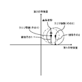
- (A) is a diagram showing an example of reference posture information
- (B) and (C) are diagrams showing an example of query information. It is a figure which showed schematically the multidimensional space for explaining the function of the threshold value setting part.
- the search unit 105 searches for a skeleton structure having a high degree of similarity to the feature amount of the search query (query state) from a plurality of skeleton structures stored in the database 110. It can be said that the search unit 105 searches for the state of a person who corresponds to the search condition (query state) from among the states of a plurality of people based on the feature amount of the skeleton structure as the process of recognizing the state of the person. Similar to classification, similarity is the distance between features of the skeletal structure.
- Bone B31 and B32 connecting the elbow A41 and the left elbow A42, respectively, connecting the right elbow A41 and the left elbow A42 to the right hand A51 and the left hand A52, respectively, and connecting the neck A2 to the right waist A61 and the left waist A62, respectively.
- a plurality of images that is, a plurality of images to be selected, which are a population when the image selection unit 630 selects an image
- the selection target image stored in the image storage unit 640 is repeatedly updated. This update includes both the addition of the selection target image and the deletion of the selection target image, but in general, the number of selection target images stored in the image storage unit 640 increases over time. go.
- the image storage unit 640 is a part of the search unit 105, that is, the image processing device 10. However, the image storage unit 640 may be located outside the image processing device 10.
- the image storage unit 640 may be a part of the database 110 described above, or may be provided separately from the database 110.
- FIG. 45 is a flowchart showing a second example of the process performed by the search unit 105 in this search method.
- the example shown in this figure is the same as the process shown in FIG. 43 except that the threshold value setting unit 620 generates the reference posture information instead of selecting the reference posture information (step S312).
- FIG. 46 is a diagram for explaining an example of processing performed by the threshold value setting unit 620 when the user inputs selection information to the image processing device 100.
- the threshold value setting unit 620 displays a multidimensional space on the screen of the terminal operated by the user. This multidimensional space is also centered on each of the plurality of features that characterize the posture. Then, on this screen, the positions of each of the plurality of selection target images stored in the image storage unit 640 are displayed. Then, the user selects a selection target image to be statistically processed on this screen. In the example shown in this figure, the user selects an area to be statistically processed in the multidimensional space. This area is the area where the user wants to classify the posture in particular detail. Then, the threshold value setting unit 620 generates reference posture information by statistically processing a plurality of selected images to be selected.
- the threshold setting unit 620 narrows the range of the distance for defining the group as the group gets closer to the reference posture. For example, the threshold value setting unit 620 makes the first threshold value for setting the group closest to the reference posture smaller than the second threshold value for setting the next closest group.
Abstract
According to the present invention, a query acquisition unit (610) acquires query information. The query information includes information indicating the relative positions of each of a plurality of key points. A threshold value setting unit (620) sets a threshold value for selecting at least one target image from a plurality of selection target images, by using the query information and reference posture information. An image selection unit (630) selects at least one target image from among a plurality of selection target images. Specifically, the image selection unit (630) selects at least one target image by using the relative positions of a plurality of key points of a person included in each of the plurality of selection target images, the query information, and the threshold value. The threshold value setting unit (620) may set a threshold value for classifying the plurality of selection target images.
Description
本発明は、画像選択装置、画像選択方法、及びプログラムに関する。
The present invention relates to an image selection device, an image selection method, and a program.
近年、監視システム等において、監視カメラの画像から人物の姿勢や行動等の状態の検出や検索を行う技術が利用されている。関連する技術として、例えば、特許文献1及び2が知られている。特許文献1には、深さ映像に含まれる人物の頭や手足等のキージョイントに基づいて、類似する人物の姿勢を検索する技術が開示されている。特許文献2には、人物の姿勢と関連しないが、画像に付加された傾き等の姿勢情報を利用して類似画像を検索する技術が開示されている。なお、その他に、人物の骨格推定に関連する技術として、非特許文献1が知られている。
In recent years, in surveillance systems and the like, techniques for detecting and searching states such as postures and behaviors of people from images of surveillance cameras have been used. As related techniques, for example, Patent Documents 1 and 2 are known. Patent Document 1 discloses a technique for searching the posture of a similar person based on key joints such as the head and limbs of the person included in the depth image. Patent Document 2 discloses a technique for searching a similar image by using posture information such as a tilt added to an image, although it is not related to the posture of a person. In addition, Non-Patent Document 1 is known as a technique related to skeleton estimation of a person.
また特許文献3には、画像から人物の骨格情報を検知し、この骨格情報を用いて人物の動作を識別することが記載されている。
Further, Patent Document 3 describes that the skeleton information of a person is detected from an image and the movement of the person is identified by using this skeleton information.
姿勢がクエリに類似している人物を含む画像を選択する場合、姿勢がクエリに類似しているか否かの判断基準は、その選択目的等によって変わり得る。このため、画像を選択するための閾値を適切に設定する技術が求められる。また、複数の画像を複数のグループに分類する場合において、この分類を行うための閾値を適切に設定する技術も求められている。
When selecting an image that includes a person whose posture is similar to the query, the criteria for determining whether or not the posture is similar to the query may change depending on the purpose of selection and the like. Therefore, a technique for appropriately setting a threshold value for selecting an image is required. Further, when classifying a plurality of images into a plurality of groups, there is also a demand for a technique for appropriately setting a threshold value for performing this classification.
本発明の目的の一例は、画像を選択または分類するための閾値を適切に設定できる技術を提供することにある。
An example of an object of the present invention is to provide a technique capable of appropriately setting a threshold value for selecting or classifying an image.
本発明によれば、基準となる姿勢を示す基準姿勢情報を用いて、複数の選択対象画像から少なくとも一つの目的画像を選択するための閾値、及び前記複数の選択対象画像を分類するための閾値の少なくとも一方を設定する閾値設定手段と、
前記閾値を用いて、前記複数の選択対象画像から前記少なくとも一つの目的画像を選択する、又は前記複数の選択対象画像を分類する画像選択手段と、
を備える画像選択装置が提供される。 According to the present invention, a threshold value for selecting at least one target image from a plurality of selection target images and a threshold value for classifying the plurality of selection target images using reference posture information indicating a reference posture. Threshold setting means for setting at least one of
An image selection means for selecting at least one target image from the plurality of selection target images or classifying the plurality of selection target images using the threshold value.
An image selection device comprising the above is provided.
本発明によれば、コンピュータが、
基準となる姿勢を示す基準姿勢情報を用いて、複数の選択対象画像から少なくとも一つの目的画像を選択するための閾値、及び前記複数の選択対象画像を分類するための閾値の少なくとも一方を設定する閾値設定処理と、
前記閾値を用いて、前記複数の選択対象画像から前記少なくとも一つの目的画像を選択する、又は前記複数の選択対象画像を分類する画像選択処理と、
を行う画像選択方法が提供される。 According to the present invention, the computer
Using the reference posture information indicating the reference posture, set at least one of the threshold value for selecting at least one target image from the plurality of selection target images and the threshold value for classifying the plurality of selection target images. Threshold setting process and
An image selection process for selecting at least one target image from the plurality of selection target images or classifying the plurality of selection target images using the threshold value.
An image selection method is provided.
本発明によれば、コンピュータに、
基準となる姿勢を示す基準姿勢情報を用いて、複数の選択対象画像から少なくとも一つの目的画像を選択するための閾値、及び前記複数の選択対象画像を分類するための閾値の少なくとも一方を設定する閾値設定機能と、
前記閾値を用いて、前記複数の選択対象画像から前記少なくとも一つの目的画像を選択する、又は前記複数の選択対象画像を分類する画像選択機能と、
を持たせるプログラムが提供される。 According to the present invention, the computer
Using the reference posture information indicating the reference posture, set at least one of the threshold value for selecting at least one target image from the plurality of selection target images and the threshold value for classifying the plurality of selection target images. Threshold setting function and
An image selection function for selecting at least one target image from the plurality of selection target images or classifying the plurality of selection target images using the threshold value.
Is provided.
本発明によれば、画像を選択または分類するための閾値を適切に設定できる。
According to the present invention, a threshold value for selecting or classifying an image can be appropriately set.
上述した目的、およびその他の目的、特徴および利点は、以下に述べる好適な実施の形態、およびそれに付随する以下の図面によってさらに明らかになる。
The above-mentioned objectives and other objectives, features and advantages will be further clarified by the preferred embodiments described below and the accompanying drawings below.
以下、本発明の実施の形態について、図面を用いて説明する。尚、すべての図面において、同様な構成要素には同様の符号を付し、適宜説明を省略する。
Hereinafter, embodiments of the present invention will be described with reference to the drawings. In all drawings, similar components are designated by the same reference numerals, and description thereof will be omitted as appropriate.
(実施の形態に至る検討)
近年、ディープラーニング等の機械学習を活用した画像認識技術が様々なシステムに応用されている。例えば、監視カメラの画像により監視を行う監視システムへの適用が進められている。監視システムに機械学習を活用することで、画像から人物の姿勢や行動等の状態をある程度把握することが可能とされつつある。 (Examination leading to the embodiment)
In recent years, image recognition techniques utilizing machine learning such as deep learning have been applied to various systems. For example, it is being applied to a surveillance system that monitors images from a surveillance camera. By utilizing machine learning for monitoring systems, it is becoming possible to grasp the state of a person's posture, behavior, etc. to some extent from images.
しかしながら、このような関連する技術では、必ずしもオンデマンドにユーザが望む人物の状態を把握できない場合がある。例えば、ユーザが検索し把握したい人物の状態を事前に特定できている場合もあれば、未知の状態のように具体的に特定できていない場合もある。そうすると、場合によっては、ユーザが検索したい人物の状態を詳細に指定することができない。また、人物の体の一部が隠れているような場合には検索等を行うことができない。関連する技術では、特定の検索条件のみからしか人物の状態を検索できないため、所望の人物の状態を柔軟に検索や分類することが困難である。
However, with such related technologies, it may not always be possible to grasp the state of the person desired by the user on demand. For example, there are cases where the state of a person that the user wants to search and grasp can be specified in advance, and there are cases where the state cannot be specifically specified, such as an unknown state. Then, in some cases, it is not possible to specify in detail the state of the person that the user wants to search. In addition, when a part of the body of a person is hidden, it is not possible to perform a search or the like. With related techniques, it is difficult to flexibly search and classify a desired person's state because the person's state can be searched only from specific search conditions.
そこで、発明者らは、オンデマンドに画像からユーザ所望の人物の状態を認識するため、非特許文献1などの骨格推定技術を利用する方法を検討した。非特許文献1に開示されたOpenPose等のように、関連する骨格推定技術では、様々なパターンの正解付けされた画像データを学習することで、人物の骨格を推定する。以下の実施の形態では、このような骨格推定技術を活用することで、人物の状態を柔軟に認識することを可能とする。
Therefore, the inventors examined a method of using a skeleton estimation technique such as Non-Patent Document 1 in order to recognize the state of a person desired by a user from an image on demand. In a related skeleton estimation technique such as OpenPose disclosed in Non-Patent Document 1, the skeleton of a person is estimated by learning image data with various patterns correctly answered. In the following embodiments, it is possible to flexibly recognize the state of a person by utilizing such a skeleton estimation technique.
なお、OpenPose等の骨格推定技術により推定される骨格構造は、関節等の特徴的な点である「キーポイント」と、キーポイント間のリンクを示す「ボーン(ボーンリンク)」とから構成される。このため、以下の実施の形態では、骨格構造について「キーポイント」と「ボーン」という用語を用いて説明するが、特に限定されない限り、「キーポイント」は人物の「関節」に対応し、「ボーン」は人物の「骨」に対応している。
The skeletal structure estimated by a skeletal estimation technique such as OpenPose is composed of "key points" which are characteristic points of joints and the like and "bones (bone links)" which indicate links between key points. .. Therefore, in the following embodiments, the skeletal structure will be described using the terms "key point" and "bone", but unless otherwise specified, the "key point" corresponds to the "joint" of a person, and " "Bone" corresponds to the "bone" of a person.
(実施の形態の概要)
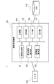
図1は、実施の形態に係る画像処理装置10の概要を示している。図1に示すように、画像処理装置10は、骨格検出部11、特徴量算出部12、及び認識部13を備えている。骨格検出部11は、カメラ等から取得される2次元画像に基づいて、複数の人物の2次元骨格構造を検出する。特徴量算出部12は、骨格検出部11により検出された複数の2次元骨格構造の特徴量を算出する。認識部13は、特徴量算出部12により算出された複数の特徴量の類似度に基づいて、複数の人物の状態の認識処理を行う。認識処理は、人物の状態の分類処理や検索処理(選択処理)等である。このため、画像処理装置10は画像選択装置としても機能する。 (Outline of embodiment)
FIG. 1 shows an outline of theimage processing apparatus 10 according to the embodiment. As shown in FIG. 1, the image processing device 10 includes a skeleton detection unit 11, a feature amount calculation unit 12, and a recognition unit 13. The skeleton detection unit 11 detects the two-dimensional skeleton structure of a plurality of people based on the two-dimensional image acquired from a camera or the like. The feature amount calculation unit 12 calculates the feature amount of the plurality of two-dimensional skeleton structures detected by the skeleton detection unit 11. The recognition unit 13 performs a recognition process for the states of a plurality of persons based on the similarity of the plurality of feature amounts calculated by the feature amount calculation unit 12. The recognition process is a classification process of a person's state, a search process (selection process), and the like. Therefore, the image processing device 10 also functions as an image selection device.
図1は、実施の形態に係る画像処理装置10の概要を示している。図1に示すように、画像処理装置10は、骨格検出部11、特徴量算出部12、及び認識部13を備えている。骨格検出部11は、カメラ等から取得される2次元画像に基づいて、複数の人物の2次元骨格構造を検出する。特徴量算出部12は、骨格検出部11により検出された複数の2次元骨格構造の特徴量を算出する。認識部13は、特徴量算出部12により算出された複数の特徴量の類似度に基づいて、複数の人物の状態の認識処理を行う。認識処理は、人物の状態の分類処理や検索処理(選択処理)等である。このため、画像処理装置10は画像選択装置としても機能する。 (Outline of embodiment)
FIG. 1 shows an outline of the
このように、実施の形態では、2次元画像から人物の2次元骨格構造を検出し、この2次元骨格構造から算出される特徴量に基づいて人物の状態の分類や検討等の認識処理を行うことで、所望の人物の状態を柔軟に認識することができる。
As described above, in the embodiment, the two-dimensional skeleton structure of the person is detected from the two-dimensional image, and the recognition process such as classification and examination of the state of the person is performed based on the feature amount calculated from the two-dimensional skeleton structure. This makes it possible to flexibly recognize the state of a desired person.
(実施の形態1)以下、図面を参照して実施の形態1について説明する。図2は、本実施の形態に係る画像処理装置100の構成を示している。画像処理装置100は、カメラ200及びデータベース(DB)110とともに画像処理システム1を構成する。画像処理装置100を含む画像処理システム1は、画像から推定される人物の骨格構造に基づき、人物の姿勢や行動等の状態を分類及び検索するシステムである。なお、画像処理装置100も、画像選択装置としても機能する。
(Embodiment 1) Hereinafter, the first embodiment will be described with reference to the drawings. FIG. 2 shows the configuration of the image processing apparatus 100 according to the present embodiment. The image processing device 100 constitutes the image processing system 1 together with the camera 200 and the database (DB) 110. The image processing system 1 including the image processing device 100 is a system for classifying and searching states such as posture and behavior of a person based on the skeleton structure of the person estimated from the image. The image processing device 100 also functions as an image selection device.
カメラ200は、2次元の画像を生成する監視カメラ等の撮像部である。カメラ200は、所定の箇所に設置されて、設置個所から撮像領域における人物等を撮像する。カメラ200は、撮像した画像(映像)を画像処理装置100へ出力可能に直接接続、もしくはネットワーク等を介して接続されている。なお、カメラ200を画像処理装置100の内部に設けてもよい。
The camera 200 is an image pickup unit such as a surveillance camera that generates a two-dimensional image. The camera 200 is installed at a predetermined location and captures a person or the like in the imaging region from the installation location. The camera 200 is directly connected so that the captured image (video) can be output to the image processing device 100, or is connected via a network or the like. The camera 200 may be provided inside the image processing device 100.
データベース110は、画像処理装置100の処理に必要な情報(データ)や処理結果等を格納するデータベースである。データベース110は、画像取得部101が取得した画像や、骨格構造検出部102の検出結果、機械学習用のデータ、特徴量算出部103が算出した特徴量、分類部104の分類結果、検索部105の検索結果等を記憶する。データベース110は、画像処理装置100と必要に応じてデータを入出力可能に直接接続、もしくはネットワーク等を介して接続されている。なお、データベース110をフラッシュメモリなどの不揮発性メモリやハードディスク装置等として、画像処理装置100の内部に設けてもよい。
The database 110 is a database that stores information (data), processing results, and the like necessary for processing of the image processing apparatus 100. The database 110 includes an image acquired by the image acquisition unit 101, a detection result of the skeletal structure detection unit 102, data for machine learning, a feature amount calculated by the feature amount calculation unit 103, a classification result of the classification unit 104, and a search unit 105. The search results etc. of are memorized. The database 110 is directly connected to the image processing device 100 so that data can be input / output as needed, or is connected via a network or the like. The database 110 may be provided inside the image processing device 100 as a non-volatile memory such as a flash memory, a hard disk device, or the like.
図2に示すように、画像処理装置100は、画像取得部101、骨格構造検出部102、特徴量算出部103、分類部104、検索部105、入力部106、及び表示部107を備えている。なお、各部(ブロック)の構成は一例であり、後述の方法(動作)が可能であれば、その他の各部で構成されてもよい。また、画像処理装置100は、例えば、プログラムを実行するパーソナルコンピュータやサーバ等のコンピュータ装置で実現されるが、1つの装置で実現してもよいし、ネットワーク上の複数の装置で実現してもよい。例えば、入力部106や表示部107等を外部の装置としてもよい。また、分類部104及び検索部105の両方を備えていてもよいし、いずれか一方のみを備えていてもよい。分類部104及び検索部105の両方、もしくは一方は、人物の状態の認識処理を行う認識部である。
As shown in FIG. 2, the image processing apparatus 100 includes an image acquisition unit 101, a skeleton structure detection unit 102, a feature amount calculation unit 103, a classification unit 104, a search unit 105, an input unit 106, and a display unit 107. .. The configuration of each part (block) is an example, and may be composed of other parts as long as the method (operation) described later is possible. Further, the image processing device 100 is realized by, for example, a computer device such as a personal computer or a server that executes a program, but it may be realized by one device or by a plurality of devices on a network. good. For example, the input unit 106, the display unit 107, and the like may be used as an external device. Further, both the classification unit 104 and the search unit 105 may be provided, or only one of them may be provided. Both or one of the classification unit 104 and the search unit 105 is a recognition unit that performs recognition processing of the state of a person.
画像取得部101は、カメラ200が撮像した人物を含む2次元の画像を取得する。画像取得部101は、例えば、所定の監視期間にカメラ200が撮像した、人物を含む画像(複数の画像を含む映像)を取得する。なお、カメラ200からの取得に限らず、予め用意された人物を含む画像をデータベース110等から取得してもよい。
The image acquisition unit 101 acquires a two-dimensional image including a person captured by the camera 200. The image acquisition unit 101 acquires, for example, an image including a person (a video including a plurality of images) captured by the camera 200 during a predetermined monitoring period. In addition to the acquisition from the camera 200, an image including a person prepared in advance may be acquired from the database 110 or the like.
骨格構造検出部102は、取得された2次元の画像に基づき、画像内の人物の2次元の骨格構造を検出する。骨格構造検出部102は、取得された画像の中で認識される全ての人物について、骨格構造を検出する。骨格構造検出部102は、機械学習を用いた骨格推定技術を用いて、認識される人物の関節等の特徴に基づき人物の骨格構造を検出する。骨格構造検出部102は、例えば、非特許文献1のOpenPose等の骨格推定技術を用いる。
The skeleton structure detection unit 102 detects the two-dimensional skeleton structure of a person in the image based on the acquired two-dimensional image. The skeleton structure detection unit 102 detects the skeleton structure of all the persons recognized in the acquired image. The skeleton structure detection unit 102 detects the skeleton structure of a person based on the characteristics such as the joints of the person to be recognized by using the skeleton estimation technique using machine learning. The skeleton structure detection unit 102 uses, for example, a skeleton estimation technique such as OpenPose of Non-Patent Document 1.
特徴量算出部103は、検出された2次元の骨格構造の特徴量を算出し、算出した特徴量を、処理対象となった画像に紐づけてデータベース110に格納する。骨格構造の特徴量は、人物の骨格の特徴を示しており、人物の骨格に基づいて人物の状態を分類や検索するための要素となる。通常、この特徴量は、複数のパラメータ(例えば後述する分類要素)を含んでいる。そして特徴量は、骨格構造の全体の特徴量でもよいし、骨格構造の一部の特徴量でもよく、骨格構造の各部のように複数の特徴量を含んでもよい。特徴量の算出方法は、機械学習や正規化等の任意の方法でよく、正規化として最小値や最大値を求めてもよい。一例として、特徴量は、骨格構造を機械学習することで得られた特徴量や、骨格構造の頭部から足部までの画像上の大きさ等である。骨格構造の大きさは、画像上の骨格構造を含む骨格領域の上下方向の高さや面積等である。上下方向(高さ方向または縦方向)は、画像における上下の方向(Y軸方向)であり、例えば、地面(基準面)に対し垂直な方向である。また、左右方向(横方向)は、画像における左右の方向(X軸方向)であり、例えば、地面に対し平行な方向である。
The feature amount calculation unit 103 calculates the feature amount of the detected two-dimensional skeletal structure, associates the calculated feature amount with the image to be processed, and stores it in the database 110. The feature amount of the skeletal structure shows the characteristics of the skeleton of the person, and is an element for classifying or searching the state of the person based on the skeleton of the person. Usually, this feature quantity includes a plurality of parameters (for example, classification elements described later). The feature amount may be an entire feature amount of the skeletal structure, a partial feature amount of the skeletal structure, or a plurality of feature amounts such as each part of the skeletal structure. The feature amount may be calculated by any method such as machine learning or normalization, and the minimum value or the maximum value may be obtained as the normalization. As an example, the feature amount is a feature amount obtained by machine learning the skeletal structure, a size on an image of the skeletal structure from the head to the foot, and the like. The size of the skeleton structure is the vertical height and area of the skeleton region including the skeleton structure on the image. The vertical direction (height direction or vertical direction) is a vertical direction (Y-axis direction) in the image, and is, for example, a direction perpendicular to the ground (reference plane). Further, the left-right direction (horizontal direction) is a left-right direction (X-axis direction) in the image, and is, for example, a direction parallel to the ground.
なお、ユーザが望む分類や検索を行うためには、分類や検索処理に対しロバスト性を有する特徴量を用いることが好ましい。例えば、ユーザが、人物の向きや体型に依存しない分類や検索を望む場合、人物の向きや体型にロバストな特徴量を使用してもよい。同じ姿勢で様々な方向に向いている人物の骨格や同じ姿勢で様々な体型の人物の骨格を学習することや、骨格の上下方向のみの特徴を抽出することで、人物の向きや体型に依存しない特徴量を得ることができる。
In addition, in order to perform the classification and search desired by the user, it is preferable to use a feature amount having robustness for the classification and search processing. For example, if the user desires a classification or search that does not depend on the orientation or body shape of the person, a robust feature amount may be used for the orientation or body shape of the person. It depends on the orientation and body shape of the person by learning the skeleton of a person who is facing in various directions in the same posture and the skeleton of a person of various body shapes in the same posture, and by extracting the characteristics of the skeleton only in the vertical direction. It is possible to obtain a feature amount that does not.
分類部104は、データベース110に格納された複数の骨格構造を、骨格構造の特徴量の類似度に基づいて分類する(クラスタリングする)。分類部104は、人物の状態の認識処理として、骨格構造の特徴量に基づいて複数の人物の状態を分類しているとも言える。類似度は、骨格構造の特徴量間の距離である。分類部104は、骨格構造の全体の特徴量の類似度により分類してもよいし、骨格構造の一部の特徴量の類似度により分類してもよく、骨格構造の第1の部分(例えば両手)及び第2の部分(例えば両足)の特徴量の類似度により分類してもよい。なお、各画像における人物の骨格構造の特徴量に基づいて人物の姿勢を分類してもよいし、時系列に連続する複数の画像における人物の骨格構造の特徴量の変化に基づいて人物の行動を分類してもよい。すなわち、分類部104は、骨格構造の特徴量に基づいて人物の姿勢や行動を含む人物の状態を分類できる。例えば、分類部104は、所定の監視期間に撮像された複数の画像における複数の骨格構造を分類対象とする。分類部104は、分類対象の特徴量間の類似度を求め、類似度の高い骨格構造が同じクラスタ(似た姿勢のグループ)となるように分類する。なお、検索と同様に、分類条件をユーザが指定できるようにしてもよい。分類部104は、骨格構造の分類結果をデータベース110に格納するとともに、表示部107に表示する。
The classification unit 104 classifies (clusters) a plurality of skeletal structures stored in the database 110 based on the similarity of the feature amounts of the skeletal structures. It can be said that the classification unit 104 classifies the states of a plurality of persons based on the feature amount of the skeletal structure as the process of recognizing the state of the person. Similarity is the distance between features of the skeletal structure. The classification unit 104 may be classified according to the similarity of the features of the whole skeleton structure, or may be classified according to the similarity of the features of a part of the skeleton structure, and the first part of the skeleton structure (for example, for example). It may be classified according to the similarity of the features of both hands) and the second part (for example, both feet). The posture of the person may be classified based on the feature amount of the skeletal structure of the person in each image, or the behavior of the person based on the change in the feature amount of the skeletal structure of the person in a plurality of consecutive images in time series. May be classified. That is, the classification unit 104 can classify the state of the person including the posture and behavior of the person based on the feature amount of the skeletal structure. For example, the classification unit 104 targets a plurality of skeletal structures in a plurality of images captured during a predetermined monitoring period. The classification unit 104 obtains the degree of similarity between the features to be classified, and classifies the skeletal structures having a high degree of similarity into the same cluster (group with similar postures). As with the search, the user may be able to specify the classification conditions. The classification unit 104 stores the classification result of the skeletal structure in the database 110 and displays it on the display unit 107.
検索部105は、データベース110に格納された複数の骨格構造の中から、検索クエリ(クエリ状態)の特徴量と類似度の高い骨格構造を検索する。検索部105は、人物の状態の認識処理として、骨格構造の特徴量に基づいて複数の人物の状態の中から、検索条件(クエリ状態)に該当する人物の状態を検索しているとも言える。分類と同様に、類似度は、骨格構造の特徴量間の距離である。検索部105は、骨格構造の全体の特徴量の類似度により検索してもよいし、骨格構造の一部の特徴量の類似度により検索してもよく、骨格構造の第1の部分(例えば両手)及び第2の部分(例えば両足)の特徴量の類似度により検索してもよい。なお、各画像における人物の骨格構造の特徴量に基づいて人物の姿勢を検索してもよいし、時系列に連続する複数の画像における人物の骨格構造の特徴量の変化に基づいて人物の行動を検索してもよい。すなわち、検索部105は、骨格構造の特徴量に基づいて人物の姿勢や行動を含む人物の状態を検索できる。例えば、検索部105は、分類対象と同様に、所定の監視期間に撮像された複数の画像における複数の骨格構造の特徴量を検索対象とする。また、分類部104が表示した分類結果の中からユーザが指定した骨格構造(姿勢)を検索クエリ(検索キー)とする。なお、分類結果に限らず、分類されていない複数の骨格構造の中から検索クエリを選択してもよいし、検索クエリとなる骨格構造をユーザが入力してもよい。検索部105は、検索対象の特徴量の中から、検索クエリの骨格構造の特徴量と類似度の高い特徴量を検索する。検索部105は、特徴量の検索結果をデータベース110に格納するとともに、表示部107に表示する。
The search unit 105 searches for a skeleton structure having a high degree of similarity to the feature amount of the search query (query state) from a plurality of skeleton structures stored in the database 110. It can be said that the search unit 105 searches for the state of a person who corresponds to the search condition (query state) from among the states of a plurality of people based on the feature amount of the skeleton structure as the process of recognizing the state of the person. Similar to classification, similarity is the distance between features of the skeletal structure. The search unit 105 may search by the similarity of the features of the whole skeleton structure, or may search by the similarity of the features of a part of the skeleton structure, and may search by the similarity of the first part of the skeleton structure (for example,). You may search by the similarity of the features of both hands) and the second part (for example, both feet). The posture of the person may be searched based on the feature amount of the skeletal structure of the person in each image, or the behavior of the person may be searched based on the change of the feature amount of the skeletal structure of the person in a plurality of consecutive images in time series. You may search for. That is, the search unit 105 can search the state of the person including the posture and behavior of the person based on the feature amount of the skeletal structure. For example, the search unit 105 searches for features of a plurality of skeletal structures in a plurality of images captured during a predetermined monitoring period, similarly to the classification target. Further, the skeleton structure (posture) specified by the user from the classification results displayed by the classification unit 104 is used as a search query (search key). Not limited to the classification result, the search query may be selected from a plurality of unclassified skeleton structures, or the user may input the skeleton structure to be the search query. The search unit 105 searches for a feature amount having a high degree of similarity to the feature amount of the skeleton structure of the search query from the feature amount of the search target. The search unit 105 stores the search result of the feature amount in the database 110 and displays it on the display unit 107.
入力部106は、画像処理装置100を操作するユーザから入力された情報を取得する入力インタフェースである。例えば、ユーザは、監視カメラの画像から不審な状態の人物を監視する監視者である。入力部106は、例えば、GUI(Graphical User Interface)であり、キーボードやマウス、タッチパネル等の入力装置から、ユーザの操作に応じた情報が入力される。例えば、入力部106は、分類部104により分類された骨格構造(姿勢)の中から、指定された人物の骨格構造を検索クエリとして受け付ける。
The input unit 106 is an input interface for acquiring information input from a user who operates the image processing device 100. For example, the user is a monitor who monitors a person in a suspicious state from an image of a surveillance camera. The input unit 106 is, for example, a GUI (Graphical User Interface), and information according to a user's operation is input from an input device such as a keyboard, a mouse, or a touch panel. For example, the input unit 106 accepts the skeleton structure of a designated person from the skeleton structures (postures) classified by the classification unit 104 as a search query.
表示部107は、画像処理装置100の動作(処理)の結果等を表示する表示部であり、例えば、液晶ディスプレイや有機EL(Electro Luminescence)ディスプレイ等のディスプレイ装置である。表示部107は、分類部104の分類結果や検索部105の検索結果を類似度等に応じてGUIに表示する。
The display unit 107 is a display unit that displays the result of the operation (processing) of the image processing device 100, and is, for example, a display device such as a liquid crystal display or an organic EL (Electro Luminescence) display. The display unit 107 displays the classification result of the classification unit 104 and the search result of the search unit 105 on the GUI according to the degree of similarity and the like.
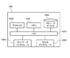
図39は、画像処理装置100のハードウェア構成例を示す図である。画像処理装置100は、バス1010、プロセッサ1020、メモリ1030、ストレージデバイス1040、入出力インタフェース1050、及びネットワークインタフェース1060を有する。
FIG. 39 is a diagram showing a hardware configuration example of the image processing device 100. The image processing device 100 includes a bus 1010, a processor 1020, a memory 1030, a storage device 1040, an input / output interface 1050, and a network interface 1060.
バス1010は、プロセッサ1020、メモリ1030、ストレージデバイス1040、入出力インタフェース1050、及びネットワークインタフェース1060が、相互にデータを送受信するためのデータ伝送路である。ただし、プロセッサ1020などを互いに接続する方法は、バス接続に限定されない。
The bus 1010 is a data transmission path for the processor 1020, the memory 1030, the storage device 1040, the input / output interface 1050, and the network interface 1060 to transmit and receive data to each other. However, the method of connecting the processors 1020 and the like to each other is not limited to the bus connection.
プロセッサ1020は、CPU(Central Processing Unit) やGPU(Graphics Processing Unit)などで実現されるプロセッサである。
The processor 1020 is a processor realized by a CPU (Central Processing Unit), a GPU (Graphics Processing Unit), or the like.
メモリ1030は、RAM(Random Access Memory)などで実現される主記憶装置である。
The memory 1030 is a main storage device realized by a RAM (RandomAccessMemory) or the like.
ストレージデバイス1040は、HDD(Hard Disk Drive)、SSD(Solid State Drive)、メモリカード、又はROM(Read Only Memory)などで実現される補助記憶装置である。ストレージデバイス1040は画像処理装置100の各機能(例えば画像取得部101、骨格構造検出部102、特徴量算出部103、分類部104、検索部105、及び入力部106)を実現するプログラムモジュールを記憶している。プロセッサ1020がこれら各プログラムモジュールをメモリ1030上に読み込んで実行することで、そのプログラムモジュールに対応する各機能が実現される。また、ストレージデバイス1040はデータベース110としても機能することもある。
The storage device 1040 is an auxiliary storage device realized by an HDD (Hard Disk Drive), SSD (Solid State Drive), memory card, ROM (Read Only Memory), or the like. The storage device 1040 stores a program module that realizes each function of the image processing device 100 (for example, an image acquisition unit 101, a skeleton structure detection unit 102, a feature amount calculation unit 103, a classification unit 104, a search unit 105, and an input unit 106). are doing. When the processor 1020 reads each of these program modules into the memory 1030 and executes them, each function corresponding to the program module is realized. The storage device 1040 may also function as a database 110.
入出力インタフェース1050は、画像処理装置100と各種入出力機器とを接続するためのインタフェースである。データベース110が画像処理装置100の外部に位置する場合、画像処理装置100は、入出力インタフェース1050を介してデータベース110と接続してもよい。
The input / output interface 1050 is an interface for connecting the image processing device 100 and various input / output devices. When the database 110 is located outside the image processing device 100, the image processing device 100 may connect to the database 110 via the input / output interface 1050.
ネットワークインタフェース1060は、画像処理装置100をネットワークに接続するためのインタフェースである。このネットワークは、例えばLAN(Local Area Network)やWAN(Wide Area Network)である。ネットワークインタフェース1060がネットワークに接続する方法は、無線接続であってもよいし、有線接続であってもよい。画像処理装置100は、ネットワークインタフェース1060を介してカメラ200と通信してもよい。データベース110が画像処理装置100の外部に位置する場合、画像処理装置100は、ネットワークインタフェース1060を介してデータベース110と接続してもよい。
The network interface 1060 is an interface for connecting the image processing device 100 to the network. This network is, for example, LAN (Local Area Network) or WAN (Wide Area Network). The method of connecting the network interface 1060 to the network may be a wireless connection or a wired connection. The image processing device 100 may communicate with the camera 200 via the network interface 1060. When the database 110 is located outside the image processing device 100, the image processing device 100 may connect to the database 110 via the network interface 1060.
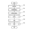
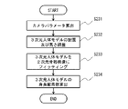
図3~図5は、本実施の形態に係る画像処理装置100の動作を示している。図3は、画像処理装置100における画像取得から検索処理までの流れを示し、図4は、図3の分類処理(S104)の流れを示し、図5は、図3の検索処理(S105)の流れを示している。
3 to 5 show the operation of the image processing apparatus 100 according to the present embodiment. FIG. 3 shows a flow from image acquisition to search processing in the image processing apparatus 100, FIG. 4 shows a flow of classification processing (S104) in FIG. 3, and FIG. 5 shows a flow of search processing (S105) in FIG. It shows the flow.
図3に示すように、画像処理装置100は、カメラ200から画像を取得する(S101)。画像取得部101は、骨格構造から分類や検索を行うために人物を撮像した画像を取得し、取得した画像をデータベース110に格納する。画像取得部101は、例えば、所定の監視期間に撮像された複数の画像を取得し、複数の画像に含まれる全ての人物について以降の処理を行う。
As shown in FIG. 3, the image processing device 100 acquires an image from the camera 200 (S101). The image acquisition unit 101 acquires an image of a person in order to classify or search from the skeleton structure, and stores the acquired image in the database 110. The image acquisition unit 101 acquires, for example, a plurality of images captured during a predetermined monitoring period, and performs subsequent processing on all the persons included in the plurality of images.
続いて、画像処理装置100は、取得した人物の画像に基づいて人物の骨格構造を検出する(S102)。図6は、骨格構造の検出例を示している。図6に示すように、監視カメラ等から取得した画像には複数の人物が含まれており、画像に含まれる各人物について骨格構造を検出する。
Subsequently, the image processing device 100 detects the skeleton structure of the person based on the acquired image of the person (S102). FIG. 6 shows an example of detecting a skeletal structure. As shown in FIG. 6, an image acquired from a surveillance camera or the like contains a plurality of persons, and the skeleton structure is detected for each person included in the image.
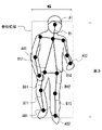
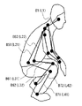
図7は、このとき検出する人体モデル300の骨格構造を示しており、図8~図10は、骨格構造の検出例を示している。骨格構造検出部102は、OpenPose等の骨格推定技術を用いて、2次元の画像から図7のような人体モデル(2次元骨格モデル)300の骨格構造を検出する。人体モデル300は、人物の関節等のキーポイントと、各キーポイントを結ぶボーンから構成された2次元モデルである。
FIG. 7 shows the skeleton structure of the human body model 300 detected at this time, and FIGS. 8 to 10 show an example of detecting the skeleton structure. The skeleton structure detection unit 102 detects the skeleton structure of the human body model (two-dimensional skeleton model) 300 as shown in FIG. 7 from the two-dimensional image by using a skeleton estimation technique such as OpenPose. The human body model 300 is a two-dimensional model composed of key points such as joints of a person and bones connecting the key points.
骨格構造検出部102は、例えば、画像の中からキーポイントとなり得る特徴点を抽出し、キーポイントの画像を機械学習した情報を参照して、人物の各キーポイントを検出する。図7の例では、人物のキーポイントとして、頭A1、首A2、右肩A31、左肩A32、右肘A41、左肘A42、右手A51、左手A52、右腰A61、左腰A62、右膝A71、左膝A72、右足A81、左足A82を検出する。さらに、これらのキーポイントを連結した人物の骨として、頭A1と首A2を結ぶボーンB1、首A2と右肩A31及び左肩A32をそれぞれ結ぶボーンB21及びボーンB22、右肩A31及び左肩A32と右肘A41及び左肘A42をそれぞれ結ぶボーンB31及びボーンB32、右肘A41及び左肘A42と右手A51及び左手A52をそれぞれ結ぶボーンB41及びボーンB42、首A2と右腰A61及び左腰A62をそれぞれ結ぶボーンB51及びボーンB52、右腰A61及び左腰A62と右膝A71及び左膝A72をそれぞれ結ぶボーンB61及びボーンB62、右膝A71及び左膝A72と右足A81及び左足A82をそれぞれ結ぶボーンB71及びボーンB72を検出する。骨格構造検出部102は、検出した人物の骨格構造をデータベース110に格納する。
The skeleton structure detection unit 102, for example, extracts feature points that can be key points from an image, and detects each key point of a person by referring to information obtained by machine learning the image of the key points. In the example of FIG. 7, the key points of the person are head A1, neck A2, right shoulder A31, left shoulder A32, right elbow A41, left elbow A42, right hand A51, left hand A52, right waist A61, left waist A62, and right knee A71. , Left knee A72, right foot A81, left foot A82 are detected. Further, as the bones of the person connecting these key points, the bone B1 connecting the head A1 and the neck A2, the bones B21 and the bone B22 connecting the neck A2 and the right shoulder A31 and the left shoulder A32, respectively, and the right shoulder A31 and the left shoulder A32 and the right. Bone B31 and B32 connecting the elbow A41 and the left elbow A42, respectively, connecting the right elbow A41 and the left elbow A42 to the right hand A51 and the left hand A52, respectively, and connecting the neck A2 to the right waist A61 and the left waist A62, respectively. Bones B51 and B52, right waist A61 and left waist A62, right knee A71 and left knee A72, respectively, bone B61 and bone B62, right knee A71 and left knee A72, right foot A81 and left foot A82, respectively. B72 is detected. The skeleton structure detection unit 102 stores the detected skeleton structure of the person in the database 110.
図8は、直立した状態の人物を検出する例である。図8では、直立した人物が正面から撮像されており、正面から見たボーンB1、ボーンB51及びボーンB52、ボーンB61及びボーンB62、ボーンB71及びボーンB72がそれぞれ重ならずに検出され、右足のボーンB61及びボーンB71は左足のボーンB62及びボーンB72よりも多少折れ曲がっている。
FIG. 8 is an example of detecting an upright person. In FIG. 8, an upright person is imaged from the front, and bones B1, bone B51 and bone B52, bones B61 and bone B62, bones B71 and bone B72 viewed from the front are detected without overlapping, and the right foot is detected. Bone B61 and Bone B71 are slightly bent more than Bone B62 and Bone B72 of the left foot.
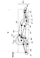
図9は、しゃがみ込んでいる状態の人物を検出する例である。図9では、しゃがみ込んでいる人物が右側から撮像されており、右側から見たボーンB1、ボーンB51及びボーンB52、ボーンB61及びボーンB62、ボーンB71及びボーンB72がそれぞれ検出され、右足のボーンB61及びボーンB71と左足のボーンB62及びボーンB72は大きく折れ曲がり、かつ、重なっている。
FIG. 9 is an example of detecting a person in a crouched state. In FIG. 9, a crouching person is imaged from the right side, bone B1, bone B51 and bone B52, bone B61 and bone B62, bone B71 and bone B72, respectively, viewed from the right side, and bone B61 on the right foot. And the bone B71 and the bone B62 and the bone B72 of the left foot are greatly bent and overlapped.
図10は、寝込んでいる状態の人物を検出する例である。図10では、寝込んでいる人物が左斜め前から撮像されており、左斜め前から見たボーンB1、ボーンB51及びボーンB52、ボーンB61及びボーンB62、ボーンB71及びボーンB72がそれぞれ検出され、右足のボーンB61及びボーンB71と左足のボーンB62及びボーンB72は折れ曲がり、かつ、重なっている。
FIG. 10 is an example of detecting a person who is sleeping. In FIG. 10, a sleeping person is imaged from diagonally left front, and bone B1, bone B51 and bone B52, bone B61 and bone B62, bone B71 and bone B72 viewed from diagonally left front are detected, respectively, and the right foot. The bones B61 and B71 of the left foot and the bones B62 and B72 of the left foot are bent and overlapped.
続いて、図3に示すように、画像処理装置100は、検出された骨格構造の特徴量を算出する(S103)。例えば、骨格領域の高さや面積を特徴量とする場合、特徴量算出部103は、骨格構造を含む領域を抽出し、その領域の高さ(画素数)や面積(画素面積)を求める。骨格領域の高さや面積は、抽出される骨格領域の端部の座標や端部のキーポイントの座標から求められる。特徴量算出部103は、求めた骨格構造の特徴量をデータベース110に格納する。なお、この骨格構造の特徴量は、上記したキーポイント及びボーンと共に、人物の姿勢を示す姿勢情報としても用いられる。
Subsequently, as shown in FIG. 3, the image processing apparatus 100 calculates the detected feature amount of the skeletal structure (S103). For example, when the height or area of the skeleton region is used as the feature amount, the feature amount calculation unit 103 extracts a region including the skeleton structure and obtains the height (number of pixels) or area (pixel area) of the region. The height and area of the skeletal region can be obtained from the coordinates of the end of the extracted skeleton region and the coordinates of the key points at the ends. The feature amount calculation unit 103 stores the obtained feature amount of the skeletal structure in the database 110. The feature amount of this skeletal structure is used as posture information indicating the posture of a person together with the above-mentioned key points and bones.
図8の例では、直立した人物の骨格構造から全てのボーンを含む骨格領域を抽出する。この場合、骨格領域の上端は頭部のキーポイントA1、骨格領域の下端は左足のキーポイントA82、骨格領域の左端は右肘のキーポイントA41、骨格領域の右端は左手のキーポイントA52となる。このため、キーポイントA1とキーポイントA82のY座標の差分から骨格領域の高さを求める。また、キーポイントA41とキーポイントA52のX座標の差分から骨格領域の幅を求め、骨格領域の高さと幅から面積を求める。
In the example of FIG. 8, the skeletal region including all bones is extracted from the skeletal structure of an upright person. In this case, the upper end of the skeletal region is the key point A1 of the head, the lower end of the skeletal region is the key point A82 of the left foot, the left end of the skeletal region is the key point A41 of the right elbow, and the right end of the skeletal region is the key point A52 of the left hand. .. Therefore, the height of the skeleton region is obtained from the difference between the Y coordinates of the key point A1 and the key point A82. Further, the width of the skeleton region is obtained from the difference between the X coordinates of the key point A41 and the key point A52, and the area is obtained from the height and width of the skeleton region.
図9の例では、しゃがみ込んだ人物の骨格構造から全てのボーンを含む骨格領域を抽出する。この場合、骨格領域の上端は頭部のキーポイントA1、骨格領域の下端は右足のキーポイントA81、骨格領域の左端は右腰のキーポイントA61、骨格領域の右端は右手のキーポイントA51となる。このため、キーポイントA1とキーポイントA81のY座標の差分から骨格領域の高さを求める。また、キーポイントA61とキーポイントA51のX座標の差分から骨格領域の幅を求め、骨格領域の高さと幅から面積を求める。
In the example of FIG. 9, the skeletal region including all bones is extracted from the skeletal structure of a crouched person. In this case, the upper end of the skeletal region is the key point A1 of the head, the lower end of the skeletal region is the key point A81 of the right foot, the left end of the skeletal region is the key point A61 of the right hip, and the right end of the skeletal region is the key point A51 of the right hand. .. Therefore, the height of the skeleton region is obtained from the difference between the Y coordinates of the key point A1 and the key point A81. Further, the width of the skeleton region is obtained from the difference between the X coordinates of the key point A61 and the key point A51, and the area is obtained from the height and width of the skeleton region.
図10の例では、画像の左右方向に寝込んだ人物の骨格構造から全てのボーンを含む骨格領域を抽出する。この場合、骨格領域の上端は左肩のキーポイントA32、骨格領域の下端は左手のキーポイントA52、骨格領域の左端は右手のキーポイントA51、骨格領域の右端は左足のキーポイントA82となる。このため、キーポイントA32とキーポイントA52のY座標の差分から骨格領域の高さを求める。また、キーポイントA51とキーポイントA82のX座標の差分から骨格領域の幅を求め、骨格領域の高さと幅から面積を求める。
In the example of FIG. 10, a skeletal region including all bones is extracted from the skeletal structure of a person who has fallen in the left-right direction of the image. In this case, the upper end of the skeleton region is the key point A32 of the left shoulder, the lower end of the skeleton region is the key point A52 of the left hand, the left end of the skeleton region is the key point A51 of the right hand, and the right end of the skeleton region is the key point A82 of the left foot. Therefore, the height of the skeleton region is obtained from the difference between the Y coordinates of the key point A32 and the key point A52. Further, the width of the skeleton region is obtained from the difference between the X coordinates of the key point A51 and the key point A82, and the area is obtained from the height and width of the skeleton region.
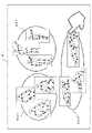
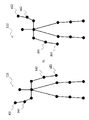
続いて、図3に示すように、画像処理装置100は、分類処理を行う(S104)。分類処理では、図4に示すように、分類部104は、算出された骨格構造の特徴量の類似度を算出し(S111)、算出された特徴量に基づいて骨格構造を分類する(S112)。分類部104は、分類対象であるデータベース110に格納されている全ての骨格構造間の特徴量の類似度を求め、最も類似度が高い骨格構造(姿勢)を同じクラスタに分類する(クラスタリングする)。さらに、分類したクラスタ間の類似度を求めて分類し、所定の数のクラスタとなるまで分類を繰り返す。図11は、骨格構造の特徴量の分類結果のイメージを示している。図11は、2次元の分類要素によるクラスタ分析のイメージであり、2つ分類要素は、例えば、骨格領域の高さと骨格領域の面積等である。図11では、分類の結果、複数の骨格構造の特徴量が3つのクラスタC1~C3に分類されている。クラスタC1~C3は、例えば、立っている姿勢、座っている姿勢、寝ている姿勢のように各姿勢に対応し、似ている姿勢ごとに骨格構造(人物)が分類される。
Subsequently, as shown in FIG. 3, the image processing apparatus 100 performs classification processing (S104). In the classification process, as shown in FIG. 4, the classification unit 104 calculates the similarity of the calculated feature amount of the skeletal structure (S111), and classifies the skeletal structure based on the calculated feature amount (S112). .. The classification unit 104 obtains the similarity of the feature quantities between all the skeletal structures stored in the database 110 to be classified, and classifies (clusters) the skeletal structures (postures) having the highest similarity into the same cluster. .. Further, the similarity between the classified clusters is obtained and classified, and the classification is repeated until a predetermined number of clusters are obtained. FIG. 11 shows an image of the classification result of the feature amount of the skeletal structure. FIG. 11 is an image of cluster analysis using a two-dimensional classification element, and the two classification elements are, for example, the height of the skeletal region and the area of the skeletal region. In FIG. 11, as a result of classification, the feature quantities of the plurality of skeletal structures are classified into three clusters C1 to C3. The clusters C1 to C3 correspond to each posture such as a standing posture, a sitting posture, and a sleeping posture, and the skeletal structure (person) is classified for each similar posture.
本実施の形態では、人物の骨格構造の特徴量に基づいて分類することにより、多様な分類方法を用いることができる。なお、分類方法は、予め設定されていてもよいし、ユーザが任意に設定できるようにしてもよい。また、後述する検索方法と同じ方法により分類を行ってもよい。つまり、検索条件と同様の分類条件により分類してもよい。例えば、分類部104は、次の分類方法により分類を行う。いずれかの分類方法を用いてもよいし、任意に選択された分類方法を組み合わせてもよい。
In this embodiment, various classification methods can be used by classifying based on the feature amount of the skeletal structure of a person. The classification method may be set in advance or may be arbitrarily set by the user. Further, the classification may be performed by the same method as the search method described later. That is, it may be classified according to the same classification conditions as the search conditions. For example, the classification unit 104 classifies by the following classification method. Any classification method may be used, or an arbitrarily selected classification method may be combined.
(分類方法1)複数の階層による分類全身の骨格構造による分類や、上半身や下半身の骨格構造による分類、腕や脚の骨格構造による分類等を階層的に組み合わせて分類する。すなわち、骨格構造の第1の部分や第2の部分の特徴量に基づいて分類し、さらに、第1の部分や第2の部分の特徴量に重みづけを行って分類してもよい。
(Classification method 1) Classification by multiple layers Classification by skeletal structure of the whole body, classification by skeletal structure of upper body and lower body, classification by skeletal structure of arms and legs, etc. are classified in a hierarchical combination. That is, the classification may be performed based on the feature amounts of the first portion and the second portion of the skeletal structure, and further, the feature amounts of the first portion and the second portion may be weighted and classified.
(分類方法2)時系列に沿った複数枚の画像による分類時系列に連続する複数の画像における骨格構造の特徴量に基づいて分類する。例えば、時系列方向に特徴量を積み重ねて、累積値に基づいて分類してもよい。さらに、連続する複数の画像における骨格構造の特徴量の変化(変化量)に基づいて分類してもよい。
(Classification method 2) Classification by multiple images along the time series Classification is based on the feature amount of the skeletal structure in a plurality of images continuous in the time series. For example, the feature quantities may be stacked in the time series direction and classified based on the cumulative value. Further, it may be classified based on the change (change amount) of the feature amount of the skeletal structure in a plurality of continuous images.
(分類方法3)骨格構造の左右を無視した分類人物の右側と左側が反対の骨格構造を同じ骨格構造として分類する。
(Classification method 3) Classification ignoring the left and right sides of the skeletal structure Classify the skeletal structures whose right and left sides are opposite to each other as the same skeletal structure.
さらに、分類部104は、骨格構造の分類結果を表示する(S113)。分類部104は、データベース110から必要な骨格構造や人物の画像を取得し、分類結果として似ている姿勢(クラスタ)ごとに骨格構造及び人物を表示部107に表示する。図12は、姿勢を3つに分類した場合の表示例を示している。例えば、図12に示すように、表示ウィンドウW1に、姿勢ごとの姿勢領域WA1~WA3を表示し、姿勢領域WA1~WA3にそれぞれ該当する姿勢の骨格構造及び人物(イメージ)を表示する。姿勢領域WA1は、例えば立っている姿勢の表示領域であり、クラスタC1に分類された、立っている姿勢に似た骨格構造及び人物を表示する。姿勢領域WA2は、例えば座っている姿勢の表示領域であり、クラスタC2に分類された、座っている姿勢に似た骨格構造及び人物を表示する。姿勢領域WA3は、例えば寝ている姿勢の表示領域であり、クラスタC2に分類された、寝ている姿勢に似た骨格構造及び人物を表示する。
Further, the classification unit 104 displays the classification result of the skeletal structure (S113). The classification unit 104 acquires images of necessary skeleton structures and people from the database 110, and displays the skeleton structure and people on the display unit 107 for each posture (cluster) similar as a classification result. FIG. 12 shows a display example when the postures are classified into three. For example, as shown in FIG. 12, the posture regions WA1 to WA3 for each posture are displayed in the display window W1, and the skeletal structure and the person (image) of the posture corresponding to each of the posture regions WA1 to WA3 are displayed. The posture area WA1 is, for example, a standing posture display area, and displays a skeletal structure and a person similar to a standing posture classified into cluster C1. The posture area WA2 is, for example, a sitting posture display area, and displays a skeletal structure and a person similar to the sitting posture classified into cluster C2. The posture area WA3 is, for example, a display area of a sleeping posture, and displays a skeletal structure and a person similar to the sleeping posture classified into cluster C2.
続いて、図3に示すように、画像処理装置100は、検索処理を行う(S105)。検索処理では、図5に示すように、検索部105は、検索条件の入力を受け付け(S121)、検索条件に基づいて骨格構造を検索する(S122)。検索部105は、入力部106から、ユーザの操作に応じて検索条件である検索クエリの入力を受け付ける。分類結果から検索クエリを入力する場合、例えば、図12の表示例では、ユーザは、表示ウィンドウW1に表示されている姿勢領域WA1~WA3の中から検索したい姿勢の骨格構造を指定(選択)する。そうすると、検索部105は、ユーザにより指定された骨格構造を検索クエリとして、検索対象であるデータベース110に格納されている全ての骨格構造の中から特徴量の類似度が高い骨格構造を検索する。検索部105は、検索クエリの骨格構造の特徴量と検索対象の骨格構造の特徴量との類似度を算出し、算出した類似度が所定の閾値よりも高い骨格構造を抽出する。検索クエリの骨格構造の特徴量は、予め算出された特徴量を使用してもよいし、検索時に求めた特徴量を使用してもよい。なお、検索クエリは、ユーザの操作に応じて骨格構造の各部を動かすことで入力してもよいし、ユーザがカメラの前で実演した姿勢を検索クエリとしてもよい。
Subsequently, as shown in FIG. 3, the image processing apparatus 100 performs a search process (S105). In the search process, as shown in FIG. 5, the search unit 105 accepts the input of the search condition (S121) and searches for the skeleton structure based on the search condition (S122). The search unit 105 receives input of a search query, which is a search condition, from the input unit 106 according to the user's operation. When inputting a search query from the classification result, for example, in the display example of FIG. 12, the user specifies (selects) the skeleton structure of the posture to be searched from the posture areas WA1 to WA3 displayed in the display window W1. .. Then, the search unit 105 uses the skeleton structure specified by the user as a search query to search for a skeleton structure having a high degree of similarity in the feature amount from all the skeleton structures stored in the database 110 to be searched. The search unit 105 calculates the similarity between the feature amount of the skeleton structure of the search query and the feature amount of the skeleton structure to be searched, and extracts the skeleton structure whose calculated similarity is higher than a predetermined threshold value. As the feature amount of the skeleton structure of the search query, the feature amount calculated in advance may be used, or the feature amount obtained at the time of search may be used. The search query may be input by moving each part of the skeleton structure according to the operation of the user, or the posture demonstrated by the user in front of the camera may be used as the search query.
本実施の形態では、分類方法と同様に、人物の骨格構造の特徴量に基づいて検索することにより、多様な検索方法を用いることができる。なお、検索方法は、予め設定されていてもよいし、ユーザが任意に設定できるようにしてもよい。例えば、検索部105は、次の検索方法により検索を行う。いずれかの検索方法を用いてもよいし、任意に選択された検索方法を組み合わせてもよい。複数の検索方法(検索条件)を論理式(例えばAND(論理積)、OR(論理和)、NOT(否定))により組み合わせて検索してもよい。例えば、検索条件を「(右手を挙げている姿勢)AND(左足を挙げている姿勢)」として検索してもよい。
In the present embodiment, as in the classification method, various search methods can be used by searching based on the feature amount of the skeletal structure of the person. The search method may be preset or may be arbitrarily set by the user. For example, the search unit 105 searches by the following search method. Either search method may be used, or an arbitrarily selected search method may be combined. A plurality of search methods (search conditions) may be combined and searched by a logical expression (for example, AND (logical product), OR (logical sum), NOT (negation)). For example, the search condition may be searched as "(posture in which the right hand is raised) AND (posture in which the left foot is raised)".
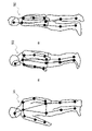
(検索方法1)高さ方向の特徴量のみによる検索人物の高さ方向の特徴量のみを用いて検索することで、人物の横方向の変化の影響を抑えることができ、人物の向きや人物の体型の変化に対しロバスト性が向上する。例えば、図13の骨格構造501~503のように、人物の向きや体型が異なる場合でも、高さ方向の特徴量は大きく変化しない。このため、骨格構造501~503では、検索時(分類時)に同じ姿勢であると判断することができる。
(Search method 1) Search by only the feature amount in the height direction By searching using only the feature amount in the height direction of the person, the influence of the lateral change of the person can be suppressed, and the direction of the person and the person can be suppressed. Improves robustness against changes in body shape. For example, as in the skeletal structures 501 to 503 of FIG. 13, even if the orientation and body shape of the person are different, the feature amount in the height direction does not change significantly. Therefore, in the skeletal structures 501 to 503, it can be determined that the postures are the same at the time of searching (at the time of classification).
(検索方法2)部分検索画像において人物の体の一部が隠れている場合、認識可能な部分の情報のみを用いて検索する。例えば、図14の骨格構造511及び512のように、左足が隠れていることにより、左足のキーポイントが検出できない場合でも、検出されている他のキーポイントの特徴量を使用して検索できる。このため、骨格構造511及び512では、検索時(分類時)に同じ姿勢であると判断することができる。つまり、全てのキーポイントではなく、一部のキーポイントの特徴量を用いて、分類や検索を行うことができる。図15の骨格構造521及び522の例では、両足の向きが異なっているものの、上半身のキーポイント(A1、A2、A31、A32、A41、A42、A51、A52)の特徴量を検索クエリとすることで、同じ姿勢であると判断することができる。また、検索したい部分(特徴点)に対して、重みを付けて検索してもよいし、類似度判定の閾値を変化させてもよい。体の一部が隠れている場合、隠れた部分を無視して検索してもよいし、隠れた部分を加味して検索してもよい。隠れた部分も含めて検索することで、同じ部位が隠れているような姿勢を検索することができる。
(Search method 2) If a part of the person's body is hidden in the partial search image, search using only the information of the recognizable part. For example, as in the skeletal structures 511 and 512 of FIG. 14, even if the key point of the left foot cannot be detected due to the hiding of the left foot, the feature amount of other detected key points can be used for the search. Therefore, in the skeletal structures 511 and 512, it can be determined that the postures are the same at the time of searching (at the time of classification). That is, it is possible to perform classification and search using the features of some key points instead of all the key points. In the examples of the skeletal structures 521 and 522 of FIG. 15, although the directions of both feet are different, the feature quantities of the key points of the upper body (A1, A2, A31, A32, A41, A42, A51, A52) are used as the search query. Therefore, it can be determined that the posture is the same. Further, the portion (feature point) to be searched may be weighted and searched, or the threshold value for determining the similarity may be changed. When a part of the body is hidden, the hidden part may be ignored and the search may be performed, or the hidden part may be added to the search. By searching including hidden parts, it is possible to search for postures in which the same part is hidden.
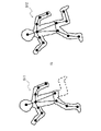
(検索方法3)骨格構造の左右を無視した検索人物の右側と左側が反対の骨格構造を同じ骨格構造として検索する。例えば、図16の骨格構造531及び532のように、右手を挙げている姿勢と、左手を挙げている姿勢を同じ姿勢として検索(分類)できる。図16の例では、骨格構造531と骨格構造532は、右手のキーポイントA51、右肘のキーポイントA41、左手のキーポイントA52、左肘のキーポイントA42の位置が異なるものの、その他のキーポイントの位置は同じである。骨格構造531の右手のキーポイントA51及び右肘のキーポイントA41と骨格構造532の左手のキーポイントA52及び左肘のキーポイントA42のうち、一方の骨格構造のキーポイントを左右反転させると、他方の骨格構造のキーポイントと同じ位置となり、また、骨格構造531の左手のキーポイントA52及び左肘のキーポイントA42と骨格構造532の右手のキーポイントA51及び右肘のキーポイントA41のうち、一方の骨格構造のキーポイントを左右反転させると、他方の骨格構造のキーポイントと同じ位置となるため、同じ姿勢と判断する。
(Search method 3) Search ignoring the left and right sides of the skeleton structure Search for the same skeleton structure on the right and left sides of the person. For example, as in the skeletal structures 531 and 532 of FIG. 16, the posture in which the right hand is raised and the posture in which the left hand is raised can be searched (classified) as the same posture. In the example of FIG. 16, the skeletal structure 531 and the skeletal structure 532 have different positions of the right hand key point A51, the right elbow key point A41, the left hand key point A52, and the left elbow key point A42, but other key points. The position of is the same. Of the key point A51 of the right hand and the key point A41 of the right elbow of the skeletal structure 531 and the key point A52 of the left hand and the key point A42 of the left elbow of the skeletal structure 532, when the key point of one of the skeletal structures is flipped left and right, the other It becomes the same position as the key point of the skeletal structure of, and one of the key point A52 of the left hand and the key point A42 of the left elbow of the skeletal structure 531 and the key point A51 of the right hand and the key point A41 of the right elbow of the skeletal structure 532. When the key point of the skeletal structure of is inverted left and right, it becomes the same position as the key point of the other skeletal structure, so it is judged that the posture is the same.
(検索方法4)縦方向と横方向の特徴量による検索人物の縦方向(Y軸方向)の特徴量のみで検索を行った後、得られた結果をさらに人物の横方向(X軸方向)の特徴量を用いて検索する。
(Search method 4) Search by features in the vertical and horizontal directions After searching only with the features in the vertical direction (Y-axis direction) of the person, the obtained results are further added to the horizontal direction (X-axis direction) of the person. Search using the features of.
(検索方法5)時系列に沿った複数枚の画像による検索時系列に連続する複数の画像における骨格構造の特徴量に基づいて検索する。例えば、時系列方向に特徴量を積み重ねて、累積値に基づいて検索してもよい。さらに、連続する複数の画像における骨格構造の特徴量の変化(変化量)に基づいて検索してもよい。
(Search method 5) Search by multiple images along the time series Search based on the feature quantity of the skeletal structure in a plurality of images continuous in the time series. For example, the feature quantities may be stacked in the time series direction and searched based on the cumulative value. Further, the search may be performed based on the change (change amount) of the feature amount of the skeletal structure in a plurality of consecutive images.
さらに、検索部105は、骨格構造の検索結果を表示する(S123)。検索部105は、データベース110から必要な骨格構造や人物の画像を取得し、検索結果として得られた骨格構造及び人物を表示部107に表示する。例えば、検索クエリ(検索条件)が複数指定されている場合、検索クエリごとに検索結果を表示する。図17は、3つの検索クエリ(姿勢)により検索した場合の表示例を示している。例えば、図17に示すように、表示ウィンドウW2において、左端部に指定された検索クエリQ10、Q20、Q30の骨格構造及び人物を表示し、検索クエリQ10、Q20、Q30の右側に各検索クエリの検索結果Q11、Q21、Q31の骨格構造及び人物を並べて表示する。
Further, the search unit 105 displays the search result of the skeletal structure (S123). The search unit 105 acquires images of necessary skeleton structures and people from the database 110, and displays the skeleton structures and people obtained as search results on the display unit 107. For example, when multiple search queries (search conditions) are specified, the search results are displayed for each search query. FIG. 17 shows a display example when searching by three search queries (postures). For example, as shown in FIG. 17, in the display window W2, the skeleton structure and the person of the search queries Q10, Q20, and Q30 specified at the left end are displayed, and each search query is displayed on the right side of the search queries Q10, Q20, and Q30. The skeletal structures and people of the search results Q11, Q21, and Q31 are displayed side by side.
検索結果を検索クエリの隣から並べて表示する順番は、該当する骨格構造が見つかった順でもよいし、類似度が高い順でもよい。部分検索の部分(特徴点)に重みを付けて検索した場合に、重み付けて計算した類似度順に表示してもよい。ユーザが選択した部分(特徴点)のみから計算した類似度順に表示してもよい。また、検索結果の画像(フレーム)を中心に、時系列の前後の画像(フレーム)を一定時間分切り出して表示してもよい。
The order in which the search results are displayed side by side from the side of the search query may be the order in which the corresponding skeletal structure is found or the order in which the degree of similarity is high. When the partial search part (feature point) is weighted and searched, the weighted and calculated similarity may be displayed in order. It may be displayed in the order of similarity calculated from only the part (feature point) selected by the user. Further, the images (frames) before and after the time series may be cut out and displayed for a certain period of time, centering on the image (frame) of the search result.
(検索方法6)本検索方法において、検索部105は、検索クエリ(以下、クエリ情報とも記載)として、上記した骨格構造を用いる。この骨格構造は、人の姿勢を示している。そして検索部105は、複数の選択対象画像から、クエリ情報が示す姿勢に類似している人を含む画像(以下、目的画像と記載)を少なくとも一つ選択する。この際、検索部105は、姿勢が類似しているか否かの判断基準となる閾値を、基準となる姿勢を示す情報(以下、基準姿勢情報と記載)とクエリ情報との差分を用いて設定する。なお、選択対象画像は静止画であってもよいし、複数のフレーム画像から構成される動画であってもよい。
(Search method 6) In this search method, the search unit 105 uses the above-mentioned skeletal structure as a search query (hereinafter, also referred to as query information). This skeletal structure shows the posture of a person. Then, the search unit 105 selects at least one image (hereinafter referred to as a target image) including a person having a posture similar to that indicated by the query information from the plurality of selection target images. At this time, the search unit 105 sets a threshold value as a criterion for determining whether or not the postures are similar by using the difference between the information indicating the reference posture (hereinafter referred to as the reference posture information) and the query information. do. The image to be selected may be a still image or a moving image composed of a plurality of frame images.
図40は、本検索方法に係る検索部105の機能構成の一例を示す図である。本図において、検索部105は、クエリ取得部610、閾値設定部620、及び画像選択部630を有している。
FIG. 40 is a diagram showing an example of the functional configuration of the search unit 105 according to this search method. In this figure, the search unit 105 has a query acquisition unit 610, a threshold value setting unit 620, and an image selection unit 630.
クエリ取得部610は、クエリ情報を取得する。クエリ情報すなわち骨格構造は、複数のキーポイントそれぞれの相対位置を示す情報を含んでいる。上記したように、複数のキーポイントは、いずれも人の身体の互いに異なる部分、例えば関節を示している。クエリ取得部610は、このクエリ情報を、クエリとして入力された画像を処理することにより生成してもよい。またクエリ取得部610は、骨格情報そのものをクエリ情報として取得してもよい。
The query acquisition unit 610 acquires query information. The query information, or skeletal structure, contains information indicating the relative position of each of the plurality of key points. As mentioned above, the key points all point to different parts of the human body, such as joints. The query acquisition unit 610 may generate this query information by processing an image input as a query. Further, the query acquisition unit 610 may acquire the skeleton information itself as the query information.
閾値設定部620は、クエリ情報及び基準姿勢情報を用いて、複数の選択対象画像から少なくとも一つの目的画像を選択するための閾値を設定する。基準姿勢情報は、複数のキーポイントの相対位置の基準的な位置すなわち基準相対位置(標準的な相対位置と表現することもできる)を含んでいる。なお、閾値の設定方法の詳細例については後述する。
The threshold value setting unit 620 sets a threshold value for selecting at least one target image from a plurality of selection target images by using the query information and the reference posture information. The reference posture information includes a reference position, that is, a reference relative position (which can also be expressed as a standard relative position) of the relative positions of a plurality of key points. A detailed example of the threshold setting method will be described later.
画像選択部630は、複数の選択対象画像から少なくとも一つの目的画像を選択する。詳細には、画像選択部630は、複数の選択対象画像それぞれに含まれる人の複数のキーポイントの相対位置、クエリ情報、及び閾値を用いて、少なくとも一つの目的画像を選択する。
The image selection unit 630 selects at least one target image from a plurality of selection target images. Specifically, the image selection unit 630 selects at least one target image using the relative positions of a plurality of key points of a person included in each of the plurality of selection target images, query information, and a threshold value.
一例として画像選択部630は、姿勢を示す複数の特徴量のそれぞれを軸とした特徴量空間における、クエリ情報からの距離が閾値以下の選択対象画像を、目的画像として選択する。ここで、検索部105は、姿勢を示す特徴量として、例えば複数のキーポイントの相対位置、又はこれらを処理した値を用いる。これらの特徴量は項目を有する。
As an example, the image selection unit 630 selects a selection target image whose distance from the query information is equal to or less than the threshold value in the feature amount space centered on each of the plurality of feature amounts indicating the posture as the target image. Here, the search unit 105 uses, for example, the relative positions of a plurality of key points or the processed values thereof as the feature amount indicating the posture. These features have items.
ここで、各キーポイントの相対位置は、例えば上記したボーンリンク、すなわち人体の構造上隣に位置するキーポイントを基準とした位置で示されてもよい。またこの相対位置は、基準となるキーポイント(以下、基準キーポイントと記載)を少なくとも一つ設定し、この基準キーポイントを基準とした位置として示されてもよい。後者の場合、基準キーポイントは、例えば首、右肩、及び左肩の少なくとも一つである。そしてキーポイントの相対位置は、この基準キーポイントを原点とした当該キーポイントの座標で示されてもよいし、基準キーポイントから当該キーポイントに至るまでのボーンリンクで示されてもよい。
Here, the relative position of each key point may be indicated by, for example, the above-mentioned bone link, that is, a position with reference to a key point located adjacent to the structure of the human body. Further, this relative position may be indicated as a position with reference to this reference key point by setting at least one reference key point (hereinafter referred to as a reference key point). In the latter case, the reference key point is, for example, at least one of the neck, right shoulder, and left shoulder. The relative position of the key point may be indicated by the coordinates of the key point with the reference key point as the origin, or may be indicated by a bone link from the reference key point to the key point.
本図に示す例において、画像選択部630が画像を選択する際の母集団となる複数の画像、すなわち複数の選択対象画像は、画像記憶部640に記憶されている。画像記憶部640に記憶されている選択対象画像は、繰り返し更新される。この更新は、選択対象画像の追加、及び選択対象画像の削除の双方が含まれるが、一般的に、画像記憶部640が記憶している選択対象画像の数は、時間が経過するにつれて増えていく。また、本図に示す例において、画像記憶部640は検索部105すなわち画像処理装置10の一部となっている。ただし画像記憶部640は、画像処理装置10の外部に位置していてもよい。なお、画像記憶部640は、上記したデータベース110の一部であってもよいし、データベース110とは別に設けられていてもよい。
In the example shown in this figure, a plurality of images, that is, a plurality of images to be selected, which are a population when the image selection unit 630 selects an image, are stored in the image storage unit 640. The selection target image stored in the image storage unit 640 is repeatedly updated. This update includes both the addition of the selection target image and the deletion of the selection target image, but in general, the number of selection target images stored in the image storage unit 640 increases over time. go. Further, in the example shown in this figure, the image storage unit 640 is a part of the search unit 105, that is, the image processing device 10. However, the image storage unit 640 may be located outside the image processing device 10. The image storage unit 640 may be a part of the database 110 described above, or may be provided separately from the database 110.
図41(A)は、基準姿勢情報の一例を示す図であり、図41(B)及び(C)は、クエリ情報の一例を示す図である。図42は、閾値設定部620の機能を説明するための多次元空間を模式的に示した図である。図42に示す多次元空間は、姿勢を特徴づける複数の特徴量のそれぞれを軸にしている。画像選択部630は、この多次元空間においてクエリ情報からの距離が閾値以下の選択対象画像を、目的画像として選択する。
FIG. 41 (A) is a diagram showing an example of reference posture information, and FIGS. 41 (B) and 41 (C) are diagrams showing an example of query information. FIG. 42 is a diagram schematically showing a multidimensional space for explaining the function of the threshold value setting unit 620. The multidimensional space shown in FIG. 42 is centered on each of a plurality of feature quantities that characterize the posture. The image selection unit 630 selects a selection target image whose distance from the query information is equal to or less than the threshold value in this multidimensional space as a target image.
図41(A)に示す例において、基準姿勢情報が示す姿勢は直立である。図41(B)に示すクエリ情報(その1)が示す姿勢は、左手を横に伸ばしている点で基準姿勢情報が示す姿勢と異なっている。一方、図41(C)に示すクエリ情報(その2)が示す姿勢は、両手を横に伸ばしている点で基準姿勢情報が示す姿勢と異なっている。このため、基準姿勢情報とクエリ情報(その2)の差は、右手が異なっている分、基準姿勢情報とクエリ情報(その1)の差よりも大きい。
In the example shown in FIG. 41 (A), the posture indicated by the reference posture information is upright. The posture shown by the query information (No. 1) shown in FIG. 41 (B) is different from the posture shown by the reference posture information in that the left hand is extended laterally. On the other hand, the posture shown by the query information (No. 2) shown in FIG. 41 (C) is different from the posture shown by the reference posture information in that both hands are extended laterally. Therefore, the difference between the reference posture information and the query information (No. 2) is larger than the difference between the reference posture information and the query information (No. 1) because the right hand is different.
図42の多次元空間において、図41(A)に示した基準姿勢情報、図41(B)に示したクエリ情報(その1)、及び図41(C)に示したクエリ情報(その2)のそれぞれの位置が示されている。目的画像を選択する際、クエリ情報が基準姿勢情報に近いほど、細かな姿勢の差が重要になる。そこで、閾値設定部620は、クエリ情報(その1)を用いて目的画像を選択するときの閾値を、クエリ情報(その2)を用いて目的画像を選択するときの閾値よりも小さくする。
In the multidimensional space of FIG. 42, the reference attitude information shown in FIG. 41 (A), the query information shown in FIG. 41 (B) (No. 1), and the query information shown in FIG. 41 (C) (No. 2). Each position of is shown. When selecting the target image, the closer the query information is to the reference posture information, the more important the small difference in posture becomes. Therefore, the threshold value setting unit 620 makes the threshold value when selecting the target image using the query information (No. 1) smaller than the threshold value when selecting the target image using the query information (No. 2).
ここで、基準姿勢情報について説明する。上記したように、基準姿勢情報は目的画像を選択するときの閾値を決定する際に用いられる。基準姿勢情報は、画像処理装置10のユーザからの入力に従って画像選択部630が取得又は生成してもよいし、画像選択部630が生成してもよい。
Here, the reference posture information will be explained. As described above, the reference posture information is used in determining the threshold value when selecting the target image. The reference posture information may be acquired or generated by the image selection unit 630 or may be generated by the image selection unit 630 according to the input from the user of the image processing device 10.
画像選択部630がユーザからの入力に従って基準姿勢情報を取得する場合、ユーザから入力される情報は、基準姿勢情報そのものであってもよいし、予め記憶されている複数の姿勢情報から基準姿勢情報として用いる情報を選択することを示してもよい。後者の例において、複数の姿勢情報のそれぞれは、互いに異なる姿勢に対応しており、かつ当該姿勢における複数のキーポイントの相対位置を含んでいる。なお、ここで用いられる複数の姿勢情報は、画像記憶部640に記憶されていてもよいし、画像記憶部640とは異なる場所に記憶されていてもよい。
When the image selection unit 630 acquires the reference posture information according to the input from the user, the information input from the user may be the reference posture information itself, or the reference posture information from a plurality of posture information stored in advance. It may be indicated to select the information to be used as. In the latter example, each of the plurality of posture information corresponds to a different posture from each other, and includes the relative positions of the plurality of key points in the posture. The plurality of posture information used here may be stored in the image storage unit 640, or may be stored in a place different from the image storage unit 640.
また、画像選択部630は、基準姿勢情報を生成する場合、例えば画像記憶部640が記憶している複数の選択対象画像を統計処理することにより基準姿勢情報を生成してもよい。ここで行われる統計処理は、例えば、少なくとも2つの選択対象画像それぞれの複数のキーポイントの相対位置を統計処理することである。ここで行われる統計処理は例えば平均であるが、これに限定されない。この統計処理を行うと、基準姿勢情報が示す姿勢は選択対象画像が示す姿勢の標準的な姿勢になる。そして、基準姿勢情報の近くには選択対象画像が密集していると推定される。このため、クエリ情報が基準姿勢情報に近いほど、クエリ情報に類似する画像が多くなるため、画像を選択する際には細かな姿勢の差が特に重要になると考えられる。
Further, when the image selection unit 630 generates the reference posture information, the reference posture information may be generated by statistically processing a plurality of selection target images stored in the image storage unit 640, for example. The statistical processing performed here is, for example, statistical processing of the relative positions of a plurality of key points of each of at least two selected images. The statistical processing performed here is, for example, an average, but is not limited to this. When this statistical processing is performed, the posture indicated by the reference posture information becomes the standard posture of the posture indicated by the selected image. Then, it is presumed that the images to be selected are densely packed near the reference posture information. Therefore, the closer the query information is to the reference posture information, the more images are similar to the query information. Therefore, it is considered that a small difference in posture becomes particularly important when selecting an image.
なお、画像選択部630は、基準姿勢情報を生成する際に、画像記憶部640が記憶しているすべての選択対象画像を用いてもよいし、ユーザによって選択された選択対象画像のみを用いてもよい。
The image selection unit 630 may use all the selection target images stored in the image storage unit 640 when generating the reference posture information, or may use only the selection target image selected by the user. May be good.
図43は、本検索方法において検索部105が行う処理の第1例を示すフローチャートである。本図に示す例において、画像選択部630は、ユーザ入力に従って基準姿勢情報を選択又は生成する。
FIG. 43 is a flowchart showing a first example of the process performed by the search unit 105 in this search method. In the example shown in this figure, the image selection unit 630 selects or generates reference posture information according to user input.
まずクエリ取得部610は、クエリ情報を取得する(ステップS300)。また閾値設定部620は、ユーザ入力に従って基準姿勢情報を選択又は生成する(ステップS310)。例えば閾値設定部620は、ユーザ入力に従っていずれかの選択対象画像を選択し、当該選択対象画像が示す姿勢情報を、基準姿勢情報とする。また閾値設定部620は、ユーザ入力に従って描かれた姿勢を、基準姿勢情報としてもよい。そして閾値設定部620は、この基準姿勢情報とクエリ情報との差を用いて、目的画像を選択するための閾値を決定する(ステップS320)。
First, the query acquisition unit 610 acquires the query information (step S300). Further, the threshold value setting unit 620 selects or generates reference posture information according to user input (step S310). For example, the threshold value setting unit 620 selects one of the selection target images according to the user input, and uses the posture information indicated by the selection target image as the reference posture information. Further, the threshold value setting unit 620 may use the posture drawn according to the user input as the reference posture information. Then, the threshold value setting unit 620 determines the threshold value for selecting the target image by using the difference between the reference posture information and the query information (step S320).
例えば閾値設定部620は、基準姿勢情報とクエリ情報との差に所定の演算を行った結果を閾値とする。一例として、閾値設定部620は、基準姿勢情報とクエリ情報との差に定数を乗ずることにより、閾値を算出してもよい。閾値設定部620は、基準姿勢情報とクエリ情報との差に定数を乗ずるとともに、さらに、画像記憶部640が記憶している複数の選択対象画像を統計処理した結果を用いることにより、閾値を設定してもよい。ここで行われる統計処理の一例は、分散を算出することである。この場合、閾値設定部620は、例えば基準姿勢情報とクエリ情報との差に、この分散及び定数のそれぞれを乗ずることにより、閾値を算出する。なお、閾値設定部620は、これら複数の算出方法を、様々な条件に応じて選択してもよい。
For example, the threshold value setting unit 620 uses the result of performing a predetermined calculation on the difference between the reference posture information and the query information as the threshold value. As an example, the threshold value setting unit 620 may calculate the threshold value by multiplying the difference between the reference posture information and the query information by a constant. The threshold value setting unit 620 multiplies the difference between the reference posture information and the query information by a constant, and further sets the threshold value by using the result of statistical processing of a plurality of selection target images stored in the image storage unit 640. You may. An example of statistical processing performed here is to calculate the variance. In this case, the threshold value setting unit 620 calculates the threshold value by, for example, multiplying the difference between the reference posture information and the query information by each of the variance and the constant. The threshold value setting unit 620 may select these plurality of calculation methods according to various conditions.
そして画像選択部630は、ステップS320で決定した閾値を用いて、画像記憶部640が記憶している複数の選択対象画像から、クエリ情報に類似する画像を選択する(ステップS330)。
Then, the image selection unit 630 selects an image similar to the query information from the plurality of selection target images stored in the image storage unit 640 using the threshold value determined in step S320 (step S330).
そして画像選択部630は、選択結果を示す情報を、例えば表示部107に表示させるために出力する(ステップS340)。
Then, the image selection unit 630 outputs information indicating the selection result, for example, to be displayed on the display unit 107 (step S340).
図44は、図43のステップS340の後に画像選択部630によって表示される画面の一例を示す図である。この画面は、画像選択部630による選択結果を示している。本図に示す例において、この画面は多次元空間を示している。この多次元空間は、姿勢を特徴づける複数の特徴量のそれぞれを軸にしている。そしてこの画面は、上記した多次元空間における目的画像の位置と、選択対象画像のうち目的画像に選ばれなかった画像の位置と、をマークで示している。ここで選択対象画像のうち目的画像に選ばれなかった画像は、すべて表示されていてもよいし、一部の画像(少なくとも一つの画像)のみが表示されてもよい。
FIG. 44 is a diagram showing an example of a screen displayed by the image selection unit 630 after step S340 in FIG. 43. This screen shows the selection result by the image selection unit 630. In the example shown in this figure, this screen shows a multidimensional space. This multidimensional space is centered on each of the plurality of features that characterize the posture. Then, on this screen, the position of the target image in the above-mentioned multidimensional space and the position of the image not selected as the target image among the selected images are indicated by marks. Here, among the images to be selected, all the images not selected as the target image may be displayed, or only a part of the images (at least one image) may be displayed.
なお、画像選択部630は、図44に示した画面においていずれかのマークが選択されると、選択されたマークに対応する画像を画像記憶部640から読み出して表示してもよい。この表示は、例えば図44に示した画面の中で行われてもよいし、別ウインドウに表示されてもよい。
When any mark is selected on the screen shown in FIG. 44, the image selection unit 630 may read out an image corresponding to the selected mark from the image storage unit 640 and display it. This display may be performed, for example, in the screen shown in FIG. 44, or may be displayed in a separate window.
また本図において、画像選択部630は、クエリ姿勢の位置を中心として半径が閾値の円又は球を、多次元空間内に表示させている。このようにすると、ユーザは、閾値の大きさ、及び選択画像の数などを視覚的に把握することができる。
Further, in this figure, the image selection unit 630 displays a circle or a sphere whose radius is a threshold centering on the position of the query posture in the multidimensional space. In this way, the user can visually grasp the size of the threshold value, the number of selected images, and the like.
図45は、本検索方法において検索部105が行う処理の第2例を示すフローチャートである。本図に示す例は、閾値設定部620が、基準姿勢情報を選択する代わりに基準姿勢情報を生成する(ステップS312)点を除いて、図43に示した処理と同様である。
FIG. 45 is a flowchart showing a second example of the process performed by the search unit 105 in this search method. The example shown in this figure is the same as the process shown in FIG. 43 except that the threshold value setting unit 620 generates the reference posture information instead of selecting the reference posture information (step S312).
ステップS312において、閾値設定部620は、例えば、画像記憶部640に記憶されているすべての選択対象画像に含まれる姿勢を統計処理(例えば平均の算出)し、その処理結果が示す情報を基準姿勢情報とする。他の例として、閾値設定部620は、複数の選択対象画像の一部を選択するための選択情報を取得し、当該選択情報が示す選択対象画像を統計処理することにより、基準姿勢情報を生成する。選択情報は、例えばユーザによって画像処理装置100に入力される。
In step S312, the threshold setting unit 620 statistically processes (for example, calculates the average) the posture included in all the selection target images stored in the image storage unit 640, and uses the information indicated by the processing result as the reference posture. It is information. As another example, the threshold value setting unit 620 acquires selection information for selecting a part of a plurality of selection target images, and statistically processes the selection target image indicated by the selection information to generate reference posture information. do. The selection information is input to the image processing apparatus 100 by the user, for example.
図46は、ユーザが選択情報を画像処理装置100に入力するときに閾値設定部620が行う処理の一例を説明するための図である。本図に示す例において、閾値設定部620は、ユーザが操作する端末の画面に多次元空間を表示させる。この多次元空間も、姿勢を特徴づける複数の特徴量のそれぞれを軸にしている。そしてこの画面には、画像記憶部640に記憶されている複数の選択対象画像それぞれの位置が表示されている。そしてユーザは、この画面において、統計処理の対象となる選択対象画像を選択する。本図に示す例では、ユーザは、多次元空間のうち統計処理の対象となる領域を選択している。この領域は、ユーザが特に細かく姿勢を分類したいと考えている領域になる。すると閾値設定部620は、選択された複数の選択対象画像を統計処理することにより、基準姿勢情報を生成する。
FIG. 46 is a diagram for explaining an example of processing performed by the threshold value setting unit 620 when the user inputs selection information to the image processing device 100. In the example shown in this figure, the threshold value setting unit 620 displays a multidimensional space on the screen of the terminal operated by the user. This multidimensional space is also centered on each of the plurality of features that characterize the posture. Then, on this screen, the positions of each of the plurality of selection target images stored in the image storage unit 640 are displayed. Then, the user selects a selection target image to be statistically processed on this screen. In the example shown in this figure, the user selects an area to be statistically processed in the multidimensional space. This area is the area where the user wants to classify the posture in particular detail. Then, the threshold value setting unit 620 generates reference posture information by statistically processing a plurality of selected images to be selected.
(検索方法6の変形例)
図47は、検索方法6の変形例に係る検索部105の機能構成の一例を示す図である。本図に示す例において、検索部105は、複数の選択対象画像を複数のグループに分類する。 (Variation example of search method 6)
FIG. 47 is a diagram showing an example of the functional configuration of thesearch unit 105 according to the modified example of the search method 6. In the example shown in this figure, the search unit 105 classifies a plurality of selected images into a plurality of groups.
図47は、検索方法6の変形例に係る検索部105の機能構成の一例を示す図である。本図に示す例において、検索部105は、複数の選択対象画像を複数のグループに分類する。 (Variation example of search method 6)
FIG. 47 is a diagram showing an example of the functional configuration of the
詳細には、検索部105は、閾値設定部620及び画像選択部630を備えているが、クエリ取得部610を備えていない。閾値設定部620は、複数の選択対象画像を複数のグループに分類するための閾値を、基準姿勢情報を用いて設定する。例えば閾値設定部620は、多次元空間における基準姿勢情報からの距離に基づいて、複数の選択対象画像を複数のグループ(例えば基準姿勢情報に最も近いグループ、2番目に近いグループ・・・)に分類する。閾値設定部620は、このグループ分けのための閾値(すなわち基準姿勢情報からの距離の範囲)を、基準姿勢情報を用いて設定する。そして画像選択部630は、この閾値を用いて、複数の選択対象画像を複数のグループに分類する。
Specifically, the search unit 105 includes a threshold setting unit 620 and an image selection unit 630, but does not include a query acquisition unit 610. The threshold value setting unit 620 sets a threshold value for classifying a plurality of selection target images into a plurality of groups by using the reference posture information. For example, the threshold value setting unit 620 divides a plurality of selected images into a plurality of groups (for example, the group closest to the reference posture information, the second closest group, and the like) based on the distance from the reference posture information in the multidimensional space. Classify. The threshold value setting unit 620 sets a threshold value for this grouping (that is, a range of distance from the reference posture information) using the reference posture information. Then, the image selection unit 630 classifies a plurality of selection target images into a plurality of groups by using this threshold value.
例えば図48に示すように、閾値設定部620は、基準姿勢にそのグループが近くなるにつれて、そのグループを定義するための距離の範囲を狭くする。例えば閾値設定部620は、基準姿勢に最も近いグループを設定するための第1の閾値を、その次に近いグループを設定するための第2の閾値よりも小さくする。
For example, as shown in FIG. 48, the threshold setting unit 620 narrows the range of the distance for defining the group as the group gets closer to the reference posture. For example, the threshold value setting unit 620 makes the first threshold value for setting the group closest to the reference posture smaller than the second threshold value for setting the next closest group.
本変形例における基準姿勢情報の取得方法(又は生成方法)は、検索方法6で説明した通りである。
The method of acquiring (or generating) the reference posture information in this modification is as described in the search method 6.
なお、検索方法6の閾値設定部620及び画像選択部630は、検索機能とともに、本変形例に示した閾値設定部620及び画像選択部630と同じ機能を有していてもよい。
The threshold value setting unit 620 and the image selection unit 630 of the search method 6 may have the same functions as the threshold value setting unit 620 and the image selection unit 630 shown in this modification, together with the search function.
以上のように、本実施の形態では、2次元画像から人物の骨格構造を検出し、検出した骨格構造の特徴量に基づいて分類や検索を行うことを可能とした。これにより、類似度が高い似た姿勢ごとに分類することができ、また、検索クエリ(検索キー)と類似度が高い似た姿勢を検索することができる。画像から似ている姿勢を分類し表示することで、ユーザが姿勢等を指定することなく、画像中の人物の姿勢を把握することができる。分類結果の中からユーザが検索クエリの姿勢を指定できるため、予めユーザが検索したい姿勢を詳細に把握していない場合でも、所望の姿勢を検索することができる。例えば、人物の骨格構造の全体や一部等を条件として分類や検索を行うことができるため、柔軟な分類や検索が可能となる。
As described above, in the present embodiment, it is possible to detect the skeletal structure of a person from a two-dimensional image and perform classification and search based on the feature amount of the detected skeletal structure. As a result, it is possible to classify by similar postures having a high degree of similarity, and it is possible to search for similar postures having a high degree of similarity with a search query (search key). By classifying and displaying similar postures from the image, the posture of the person in the image can be grasped without the user specifying the posture or the like. Since the user can specify the posture of the search query from the classification results, the desired posture can be searched even if the user does not know the posture to be searched in detail in advance. For example, since it is possible to perform classification and search on the condition of the whole or part of the skeleton structure of a person, flexible classification and search is possible.
また、検索方法6によれば、クエリ情報を用いて画像を選択する際に、クエリ情報と基準姿勢情報との差を用いて、画像を選択する際の閾値を決定する。このため、画像を選択するための閾値を適切に設定できる。よって、選択結果がユーザの意図に沿う可能性は高くなる。
Further, according to the search method 6, when selecting an image using the query information, the threshold value for selecting the image is determined by using the difference between the query information and the reference posture information. Therefore, the threshold value for selecting an image can be appropriately set. Therefore, there is a high possibility that the selection result will meet the user's intention.
また、検索方法6の変形例によれば、基準姿勢情報を用いて画像を分類する場合において、分類を行うための閾値を設定することができる。
Further, according to the modification of the search method 6, when classifying images using the reference posture information, it is possible to set a threshold value for classifying.
(実施の形態2)以下、図面を参照して実施の形態2について説明する。本実施の形態では、実施の形態1における特徴量算出の具体例について説明する。本実施の形態では、人物の身長を用いて正規化することで特徴量を求める。その他については、実施の形態1と同様である。
(Embodiment 2) Hereinafter, the second embodiment will be described with reference to the drawings. In this embodiment, a specific example of feature amount calculation in the first embodiment will be described. In the present embodiment, the feature amount is obtained by normalizing using the height of the person. Others are the same as those in the first embodiment.
図18は、本実施の形態に係る画像処理装置100の構成を示している。図18に示すように、画像処理装置100は、実施の形態1の構成に加えて、さらに身長算出部108を備える。なお、特徴量算出部103と身長算出部108を一つの処理部としてもよい。
FIG. 18 shows the configuration of the image processing apparatus 100 according to the present embodiment. As shown in FIG. 18, the image processing apparatus 100 further includes a height calculation unit 108 in addition to the configuration of the first embodiment. The feature amount calculation unit 103 and the height calculation unit 108 may be combined into one processing unit.
身長算出部(身長推定部)108は、骨格構造検出部102により検出された2次元の骨格構造に基づき、2次元の画像内の人物の直立時の高さ(身長画素数という)を算出(推定)する。身長画素数は、2次元の画像における人物の身長(2次元画像空間上の人物の全身の長さ)であるとも言える。身長算出部108は、検出された骨格構造の各ボーンの長さ(2次元画像空間上の長さ)から身長画素数(ピクセル数)を求める。
The height calculation unit (height estimation unit) 108 calculates the height of the person in the two-dimensional image when standing upright (referred to as the number of height pixels) based on the two-dimensional skeleton structure detected by the skeleton structure detection unit 102 (referred to as the number of height pixels). presume. It can also be said that the number of height pixels is the height of the person in the two-dimensional image (the length of the whole body of the person in the two-dimensional image space). The height calculation unit 108 obtains the number of height pixels (number of pixels) from the length (length on the two-dimensional image space) of each bone of the detected skeleton structure.
以下の例では、身長画素数を求める方法として具体例1~3を用いる。なお、具体例1~3のいずれかの方法を用いてもよいし、任意に選択される複数の方法を組み合わせて用いてもよい。具体例1では、骨格構造の各ボーンのうち、頭部から足部までのボーンの長さを合計することで、身長画素数を求める。骨格構造検出部102(骨格推定技術)が頭頂と足元を出力しない場合は、必要に応じて定数を乗じて補正することもできる。具体例2では、各ボーンの長さと全身の長さ(2次元画像空間上の身長)との関係を示す人体モデルを用いて、身長画素数を算出する。具体例3では、3次元人体モデルを2次元骨格構造にフィッティング(あてはめる)することで、身長画素数を算出する。
In the following examples, specific examples 1 to 3 are used as a method for obtaining the number of height pixels. In addition, any of the methods of Specific Examples 1 to 3 may be used, or a plurality of arbitrarily selected methods may be used in combination. In Specific Example 1, the number of height pixels is obtained by summing the lengths of the bones from the head to the foot among the bones of the skeletal structure. If the skeleton structure detection unit 102 (skeleton estimation technique) does not output the crown and feet, it can be corrected by multiplying by a constant if necessary. In Specific Example 2, the number of height pixels is calculated using a human body model showing the relationship between the length of each bone and the length of the whole body (height on a two-dimensional image space). In Specific Example 3, the number of height pixels is calculated by fitting (fitting) a three-dimensional human body model to a two-dimensional skeleton structure.
本実施の形態の特徴量算出部103は、算出された人物の身長画素数に基づいて、人物の骨格構造(骨格情報)を正規化する正規化部である。特徴量算出部103は、正規化した骨格構造の特徴量(正規化値)をデータベース110に格納する。特徴量算出部103は、骨格構造に含まれる各キーポイント(特徴点)の画像上での高さを、身長画素数で正規化する。本実施の形態では、例えば、高さ方向は、画像の2次元座標(X-Y座標)空間における上下の方向(Y軸方向)である。この場合、キーポイントの高さは、キーポイントのY座標の値(画素数)から求めることができる。あるいは、高さ方向は、実世界の3次元座標空間における地面(基準面)に対し垂直な鉛直軸の方向を、2次元座標空間に投影した鉛直投影軸の方向(鉛直投影方向)でもよい。この場合、キーポイントの高さは、実世界における地面に対し垂直な軸を、カメラパラメータに基づいて2次元座標空間に投影した鉛直投影軸を求め、この鉛直投影軸に沿った値(画素数)から求めることができる。なお、カメラパラメータは、画像の撮像パラメータであり、例えば、カメラパラメータは、カメラ200の姿勢、位置、撮像角度、焦点距離等である。カメラ200により、予め長さや位置が分かっている物体を撮像し、その画像からカメラパラメータを求めることができる。撮像された画像の両端ではひずみが発生し、実世界の鉛直方向と画像の上下方向が合わない場合がある。これに対し、画像を撮影したカメラのパラメータを使用することで、実世界の鉛直方向が画像中でどの程度傾いているのかが分かる。このため、カメラパラメータに基づいて画像中に投影した鉛直投影軸に沿ったキーポイントの値を身長で正規化することで、実世界と画像のずれを考慮してキーポイントを特徴量化することができる。なお、左右方向(横方向)は、画像の2次元座標(X-Y座標)空間における左右の方向(X軸方向)であり、または、実世界の3次元座標空間における地面に対し平行な方向を、2次元座標空間に投影した方向である。
The feature amount calculation unit 103 of the present embodiment is a normalization unit that normalizes the skeletal structure (skeleton information) of a person based on the calculated number of height pixels of the person. The feature amount calculation unit 103 stores the feature amount (normalized value) of the normalized skeletal structure in the database 110. The feature amount calculation unit 103 normalizes the height of each key point (feature point) included in the skeleton structure on the image by the number of height pixels. In the present embodiment, for example, the height direction is the vertical direction (Y-axis direction) in the two-dimensional coordinate (XY coordinate) space of the image. In this case, the height of the key point can be obtained from the value (number of pixels) of the Y coordinate of the key point. Alternatively, the height direction may be the direction of the vertical axis perpendicular to the ground (reference plane) in the three-dimensional coordinate space in the real world, and the direction of the vertical projection axis projected onto the two-dimensional coordinate space (vertical projection direction). In this case, the height of the key point is the vertical projection axis obtained by projecting the axis perpendicular to the ground in the real world onto the two-dimensional coordinate space based on the camera parameters, and the value along this vertical projection axis (number of pixels). ) Can be obtained. The camera parameters are image imaging parameters, and for example, the camera parameters are the posture, position, imaging angle, focal length, and the like of the camera 200. The camera 200 can take an image of an object whose length and position are known in advance, and obtain camera parameters from the image. Distortion occurs at both ends of the captured image, and the vertical direction of the real world may not match the vertical direction of the image. On the other hand, by using the parameters of the camera that took the image, you can see how much the vertical direction in the real world is tilted in the image. Therefore, by normalizing the value of the key point along the vertical projection axis projected in the image based on the camera parameters by height, it is possible to characterize the key point in consideration of the deviation between the real world and the image. can. The left-right direction (horizontal direction) is the left-right direction (X-axis direction) in the two-dimensional coordinate (XY coordinates) space of the image, or the direction parallel to the ground in the three-dimensional coordinate space in the real world. Is the direction projected onto the two-dimensional coordinate space.
図19~図23は、本実施の形態に係る画像処理装置100の動作を示している。図19は、画像処理装置100における画像取得から検索処理までの流れを示し、図20~図22は、図19の身長画素数算出処理(S201)の具体例1~3の流れを示し、図23は、図19の正規化処理(S202)の流れを示している。
19 to 23 show the operation of the image processing apparatus 100 according to the present embodiment. 19 shows a flow from image acquisition to search processing in the image processing apparatus 100, and FIGS. 20 to 22 show the flow of specific examples 1 to 3 of the height pixel number calculation process (S201) of FIG. 23 shows the flow of the normalization process (S202) of FIG.
図19に示すように、本実施の形態では、実施の形態1における特徴量算出処理(S103)として、身長画素数算出処理(S201)及び正規化処理(S202)を行う。その他については実施の形態1と同様である。
As shown in FIG. 19, in the present embodiment, the height pixel number calculation process (S201) and the normalization process (S202) are performed as the feature amount calculation process (S103) in the first embodiment. Others are the same as those in the first embodiment.
画像処理装置100は、画像取得(S101)及び骨格構造検出(S102)に続いて、検出された骨格構造に基づいて身長画素数算出処理を行う(S201)。この例では、図24に示すように、画像における直立時の人物の骨格構造の高さを身長画素数(h)とし、画像の人物の状態における骨格構造の各キーポイントの高さをキーポイント高さ(yi)とする。以下、身長画素数算出処理の具体例1~3について説明する。
The image processing apparatus 100 performs height pixel number calculation processing based on the detected skeleton structure (S201) following image acquisition (S101) and skeleton structure detection (S102). In this example, as shown in FIG. 24, the height of the skeleton structure of the person standing upright in the image is the height pixel number (h), and the height of each key point of the skeleton structure in the state of the person in the image is the key point. Let it be the height (yi). Hereinafter, specific examples 1 to 3 of the height pixel number calculation process will be described.
<具体例1>具体例1では、頭部から足部までのボーンの長さを用いて身長画素数を求める。具体例1では、図20に示すように、身長算出部108は、各ボーンの長さを取得し(S211)、取得した各ボーンの長さを合計する(S212)。
<Specific Example 1> In Specific Example 1, the number of height pixels is obtained using the length of the bone from the head to the foot. In Specific Example 1, as shown in FIG. 20, the height calculation unit 108 acquires the length of each bone (S211) and totals the lengths of the acquired bones (S212).
身長算出部108は、人物の頭部から足部の2次元の画像上のボーンの長さを取得し、身長画素数を求める。すなわち、骨格構造を検出した画像から、図24のボーンのうち、ボーンB1(長さL1)、ボーンB51(長さL21)、ボーンB61(長さL31)及びボーンB71(長さL41)、もしくは、ボーンB1(長さL1)、ボーンB52(長さL22)、ボーンB62(長さL32)及びボーンB72(長さL42)の各長さ(画素数)を取得する。各ボーンの長さは、2次元の画像における各キーポイントの座標から求めることができる。これらを合計した、L1+L21+L31+L41、もしくは、L1+L22+L32+L42に補正定数を乗じた値を身長画素数(h)として算出する。両方の値を算出できる場合、例えば、長い方の値を身長画素数とする。すなわち、各ボーンは正面から撮像された場合が画像中での長さが最も長くなり、カメラに対して奥行き方向に傾くと短く表示される。従って、長いボーンの方が正面から撮像されている可能性が高く、真実の値に近いと考えられる。このため、長い方の値を選択することが好ましい。
The height calculation unit 108 acquires the length of the bone on the two-dimensional image of the foot from the head of the person, and obtains the number of height pixels. That is, from the image in which the skeletal structure is detected, among the bones of FIG. 24, bone B1 (length L1), bone B51 (length L21), bone B61 (length L31) and bone B71 (length L41), or , Bone B1 (length L1), bone B52 (length L22), bone B62 (length L32), and bone B72 (length L42) are acquired. The length of each bone can be obtained from the coordinates of each key point in the two-dimensional image. The sum of these is calculated as the height pixel number (h) by multiplying L1 + L21 + L31 + L41 or L1 + L22 + L32 + L42 by a correction constant. When both values can be calculated, for example, the longer value is taken as the number of height pixels. That is, each bone has the longest length in the image when it is imaged from the front, and it is displayed short when it is tilted in the depth direction with respect to the camera. Therefore, it is more likely that the longer bone is imaged from the front, which is considered to be closer to the true value. Therefore, it is preferable to select the longer value.
図25の例では、ボーンB1、ボーンB51及びボーンB52、ボーンB61及びボーンB62、ボーンB71及びボーンB72がそれぞれ重ならずに検出されている。これらのボーンの合計である、L1+L21+L31+L41、及び、L1+L22+L32+L42を求め、例えば、検出されたボーンの長さが長い左足側のL1+L22+L32+L42に補正定数を乗じた値を身長画素数とする。
In the example of FIG. 25, bone B1, bone B51 and bone B52, bone B61 and bone B62, bone B71 and bone B72 are detected without overlapping. The total of these bones, L1 + L21 + L31 + L41 and L1 + L22 + L32 + L42, is obtained, and for example, the value obtained by multiplying L1 + L22 + L32 + L42 on the left foot side where the detected bone length is long by a correction constant is taken as the height pixel number.
図26の例では、ボーンB1、ボーンB51及びボーンB52、ボーンB61及びボーンB62、ボーンB71及びボーンB72がそれぞれ検出され、右足のボーンB61及びボーンB71と左足のボーンB62及びボーンB72が重なっている。これらのボーンの合計である、L1+L21+L31+L41、及び、L1+L22+L32+L42を求め、例えば、検出されたボーンの長さが長い右足側のL1+L21+L31+L41に補正定数を乗じた値を身長画素数とする。
In the example of FIG. 26, bone B1, bone B51 and bone B52, bone B61 and bone B62, bone B71 and bone B72 are detected, respectively, and the right foot bone B61 and bone B71 and the left foot bone B62 and bone B72 overlap each other. .. The total of these bones, L1 + L21 + L31 + L41 and L1 + L22 + L32 + L42, is obtained, and for example, the value obtained by multiplying L1 + L21 + L31 + L41 on the right foot side where the detected bone length is long by a correction constant is taken as the height pixel number.
図27の例では、ボーンB1、ボーンB51及びボーンB52、ボーンB61及びボーンB62、ボーンB71及びボーンB72がそれぞれ検出され、右足のボーンB61及びボーンB71と左足のボーンB62及びボーンB72が重なっている。これらのボーンの合計である、L1+L21+L31+L41、及び、L1+L22+L32+L42を求め、例えば、検出されたボーンの長さが長い左足側のL1+L22+L32+L42に補正定数を乗じた値を身長画素数とする。
In the example of FIG. 27, bone B1, bone B51 and bone B52, bone B61 and bone B62, bone B71 and bone B72 are detected, respectively, and the right foot bone B61 and bone B71 and the left foot bone B62 and bone B72 overlap each other. .. The total of these bones, L1 + L21 + L31 + L41 and L1 + L22 + L32 + L42, is obtained, and for example, the value obtained by multiplying L1 + L22 + L32 + L42 on the left foot side where the detected bone length is long by a correction constant is taken as the height pixel number.
具体例1では、頭から足までのボーンの長さを合計することで身長を求めることができるため、簡易な方法で身長画素数を求めることができる。また、機械学習を用いた骨格推定技術により、少なくとも頭から足までの骨格を検出できればよいため、しゃがみ込んでいる状態など、必ずしも人物の全体が画像に写っていない場合でも精度よく身長画素数を推定することができる。
In Specific Example 1, the height can be calculated by summing the lengths of the bones from the head to the feet, so the number of height pixels can be calculated by a simple method. In addition, since it is only necessary to detect the skeleton from the head to the feet by skeleton estimation technology using machine learning, the number of height pixels can be accurately calculated even when the entire person is not always shown in the image, such as when crouching down. Can be estimated.
<具体例2>具体例2では、2次元骨格構造に含まれる骨の長さと2次元画像空間上の人物の全身の長さとの関係を示す2次元骨格モデルを用いて身長画素数を求める。
<Specific Example 2> In Specific Example 2, the number of height pixels is obtained using a two-dimensional skeleton model showing the relationship between the length of the bone included in the two-dimensional skeleton structure and the length of the whole body of the person in the two-dimensional image space.
図28は、具体例2で用いる、2次元画像空間上の各ボーンの長さと2次元画像空間上の全身の長さとの関係を示す人体モデル(2次元骨格モデル)301である。図28に示すように、平均的な人物の各ボーンの長さと全身の長さとの関係(全身の長さに対する各ボーンの長さの割合)を、人体モデル301の各ボーンに対応付ける。例えば、頭のボーンB1の長さは全身の長さ×0.2(20%)であり、右手のボーンB41の長さは全身の長さ×0.15(15%)であり、右足のボーンB71の長さは全身の長さ×0.25(25%)である。このような人体モデル301の情報をデータベース110に記憶しておくことで、各ボーンの長さから平均的な全身の長さを求めることができる。平均的な人物の人体モデルの他に、年代、性別、国籍等の人物の属性ごとに人体モデルを用意してもよい。これにより、人物の属性に応じて適切に全身の長さ(身長)を求めることができる。
FIG. 28 is a human body model (two-dimensional skeleton model) 301 showing the relationship between the length of each bone in the two-dimensional image space and the length of the whole body in the two-dimensional image space used in the second embodiment. As shown in FIG. 28, the relationship between the length of each bone of an average person and the length of the whole body (the ratio of the length of each bone to the length of the whole body) is associated with each bone of the human body model 301. For example, the length of the bone B1 of the head is the length of the whole body × 0.2 (20%), the length of the bone B41 of the right hand is the length of the whole body × 0.15 (15%), and the length of the right foot. The length of the bone B71 is the length of the whole body × 0.25 (25%). By storing the information of the human body model 301 in the database 110, the average whole body length can be obtained from the length of each bone. In addition to the human body model of an average person, a human body model may be prepared for each attribute of the person such as age, gender, and nationality. As a result, the length (height) of the whole body can be appropriately obtained according to the attributes of the person.
具体例2では、図21に示すように、身長算出部108は、各ボーンの長さを取得する(S221)。身長算出部108は、検出された骨格構造において、全てのボーンの長さ(2次元画像空間上の長さ)を取得する。図29は、しゃがみ込んでいる状態の人物を右斜め後ろから撮像し、骨格構造を検出した例である。この例では、人物の顔や左側面が写っていないことから、頭のボーンと左腕及び左手のボーンが検出できていない。このため、検出されているボーンB21、B22、B31、B41、B51、B52、B61、B62、B71、B72の各長さを取得する。
In Specific Example 2, as shown in FIG. 21, the height calculation unit 108 acquires the length of each bone (S221). The height calculation unit 108 acquires the lengths (lengths in the two-dimensional image space) of all the bones in the detected skeletal structure. FIG. 29 is an example in which a person in a crouched state is imaged from diagonally right behind and the skeletal structure is detected. In this example, since the face and left side of the person are not shown, the bones of the head, the left arm, and the bones of the left hand cannot be detected. Therefore, the lengths of the detected bones B21, B22, B31, B41, B51, B52, B61, B62, B71, and B72 are acquired.
続いて、身長算出部108は、図21に示すように、人体モデルに基づき、各ボーンの長さから身長画素数を算出する(S222)。身長算出部108は、図28のような、各ボーンと全身の長さとの関係を示す人体モデル301を参照し、各ボーンの長さから身長画素数を求める。例えば、右手のボーンB41の長さが全身の長さ×0.15であるため、ボーンB41の長さ/0.15によりボーンB41に基づいた身長画素数を求める。また、右足のボーンB71の長さが全身の長さ×0.25であるため、ボーンB71の長さ/0.25によりボーンB71に基づいた身長画素数を求める。
Subsequently, as shown in FIG. 21, the height calculation unit 108 calculates the number of height pixels from the length of each bone based on the human body model (S222). The height calculation unit 108 refers to the human body model 301 showing the relationship between each bone and the length of the whole body as shown in FIG. 28, and obtains the number of height pixels from the length of each bone. For example, since the length of the bone B41 on the right hand is the length of the whole body × 0.15, the number of height pixels based on the bone B41 is obtained from the length of the bone B41 / 0.15. Further, since the length of the bone B71 of the right foot is the length of the whole body × 0.25, the number of height pixels based on the bone B71 is obtained from the length of the bone B71 / 0.25.
このとき参照する人体モデルは、例えば、平均的な人物の人体モデルであるが、年代、性別、国籍等の人物の属性に応じて人体モデルを選択してもよい。例えば、撮像した画像に人物の顔が写っている場合、顔に基づいて人物の属性を識別し、識別した属性に対応する人体モデルを参照する。属性ごとの顔を機械学習した情報を参照し、画像の顔の特徴から人物の属性を認識することができる。また、画像から人物の属性が識別できない場合に、平均的な人物の人体モデルを用いてもよい。
The human body model referred to at this time is, for example, a human body model of an average person, but a human body model may be selected according to the attributes of the person such as age, gender, and nationality. For example, when a person's face is shown in the captured image, the attribute of the person is identified based on the face, and the human body model corresponding to the identified attribute is referred to. It is possible to recognize a person's attributes from the facial features of the image by referring to the information obtained by machine learning the face for each attribute. Further, when the attribute of the person cannot be identified from the image, the human body model of the average person may be used.
また、ボーンの長さから算出した身長画素数をカメラパラメータにより補正してもよい。例えばカメラを高い位置において、人物を見下ろすように撮影した場合、二次元骨格構造において肩幅のボーン等の横の長さはカメラの俯角の影響を受けないが、首-腰のボーン等の縦の長さは、カメラの俯角が大きくなる程小さくなる。そうすると、肩幅のボーン等の横の長さから算出した身長画素数が実際より大きくなる傾向がある。そこで、カメラパラメータを活用すると、人物がどの程度の角度でカメラに見下ろされているかがわかるため、この俯角の情報を使って正面から撮影したような二次元骨格構造に補正することができる。これによって、より正確に身長画素数を算出できる。
Further, the number of height pixels calculated from the length of the bone may be corrected by the camera parameter. For example, when the camera is taken at a high position and looking down at a person, the horizontal length of the shoulder-width bones, etc. is not affected by the depression angle of the camera in the two-dimensional skeletal structure, but the vertical length of the neck-waist bones, etc. The length decreases as the depression angle of the camera increases. Then, the number of height pixels calculated from the horizontal length of the shoulder-width bones and the like tends to be larger than the actual number. Therefore, by utilizing the camera parameters, it is possible to know the angle at which the person is looking down at the camera, and this information on the depression angle can be used to correct the two-dimensional skeleton structure as if it were taken from the front. This makes it possible to calculate the number of height pixels more accurately.
続いて、身長算出部108は、図21に示すように、身長画素数の最適値を算出する(S223)。身長算出部108は、ボーンごとに求めた身長画素数から身長画素数の最適値を算出する。例えば、図30に示すような、ボーンごとに求めた身長画素数のヒストグラムを生成し、その中で大きい身長画素数を選択する。つまり、複数のボーンに基づいて求められた複数の身長画素数の中で他よりも長い身長画素数を選択する。例えば、上位30%を有効な値とし、図30ではボーンB71、B61、B51による身長画素数を選択する。選択した身長画素数の平均を最適値として求めてもよいし、最も大きい身長画素数を最適値としてもよい。2次元画像のボーンの長さから身長を求めるため、ボーンを正面からできていない場合、すなわち、ボーンがカメラから見て奥行き方向に傾いて撮像された場合、ボーンの長さが正面から撮像した場合よりも短くなる。そうすると、身長画素数が大きい値は、身長画素数が小さい値よりも、正面から撮像された可能性が高く、より尤もらしい値となることから、より大きい値を最適値とする。
Subsequently, the height calculation unit 108 calculates the optimum value of the number of height pixels as shown in FIG. 21 (S223). The height calculation unit 108 calculates the optimum value of the number of height pixels from the number of height pixels obtained for each bone. For example, as shown in FIG. 30, a histogram of the number of height pixels obtained for each bone is generated, and a large number of height pixels is selected from the histogram. That is, the number of height pixels longer than the others is selected from the plurality of height pixels obtained based on the plurality of bones. For example, the upper 30% is set as a valid value, and in FIG. 30, the number of height pixels by bones B71, B61, and B51 is selected. The average number of selected height pixels may be obtained as the optimum value, or the largest number of height pixels may be used as the optimum value. Since the height is calculated from the length of the bone in the 2D image, the length of the bone is taken from the front when the bone is not made from the front, that is, when the bone is tilted in the depth direction when viewed from the camera. It will be shorter than the case. Then, a value having a large number of height pixels is more likely to be imaged from the front than a value having a small number of height pixels, and is a more plausible value. Therefore, a larger value is set as the optimum value.
具体例2では、2次元画像空間上のボーンと全身の長さとの関係を示す人体モデルを用いて、検出した骨格構造のボーンに基づき身長画素数を求めるため、頭から足までの全ての骨格が得られない場合でも、一部のボーンから身長画素数を求めることができる。特に、複数のボーンから求められた値のうち、より大きい値を採用することで、精度よく身長画素数を推定することができる。
In Specific Example 2, the number of height pixels is calculated based on the detected bones of the skeleton structure using a human body model showing the relationship between the bones in the two-dimensional image space and the length of the whole body, so that all the skeletons from the head to the feet are obtained. Even if is not obtained, the number of height pixels can be obtained from some bones. In particular, the number of height pixels can be estimated accurately by adopting a larger value among the values obtained from a plurality of bones.
<具体例3>具体例3では、2次元骨格構造を3次元人体モデル(3次元骨格モデル)にフィッティングさせて、フィッティングした3次元人体モデルの身長画素数を用いて全身の骨格ベクトルを求める。
<Specific Example 3> In Specific Example 3, the two-dimensional skeleton structure is fitted to the three-dimensional human body model (three-dimensional skeleton model), and the skeleton vector of the whole body is obtained using the number of height pixels of the fitted three-dimensional human body model.
具体例3では、図22に示すように、身長算出部108は、まず、カメラ200の撮像した画像に基づき、カメラパラメータを算出する(S231)。身長算出部108は、カメラ200が撮像した複数の画像の中から、予め長さが分かっている物体を抽出し、抽出した物体の大きさ(画素数)からカメラパラメータを求める。なお、カメラパラメータを予め求めておき、求めておいたカメラパラメータを必要に応じて取得してもよい。
In Specific Example 3, as shown in FIG. 22, the height calculation unit 108 first calculates the camera parameters based on the image captured by the camera 200 (S231). The height calculation unit 108 extracts an object whose length is known in advance from a plurality of images captured by the camera 200, and obtains a camera parameter from the size (number of pixels) of the extracted object. The camera parameters may be obtained in advance, and the obtained camera parameters may be acquired as needed.
続いて、身長算出部108は、3次元人体モデルの配置及び高さを調整する(S232)。身長算出部108は、検出された2次元骨格構造に対し、身長画素数算出用の3次元人体モデルを用意し、カメラパラメータに基づいて、同じ2次元画像内に配置する。具体的には、カメラパラメータと、2次元骨格構造から、「実世界におけるカメラと人物の相対的な位置関係」を特定する。例えば、仮にカメラの位置を座標(0,0,0)としたときに、人物が立っている(または座っている)位置の座標(x,y,z)を特定する。そして、特定した人物と同じ位置(x,y,z)に3次元人体モデルを配置して撮像した場合の画像を想定することで、2次元骨格構造と3次元人体モデルを重ね合わせる。
Subsequently, the height calculation unit 108 adjusts the arrangement and height of the three-dimensional human body model (S232). The height calculation unit 108 prepares a three-dimensional human body model for calculating the number of height pixels for the detected two-dimensional skeleton structure, and arranges the three-dimensional human body model in the same two-dimensional image based on the camera parameters. Specifically, the "relative positional relationship between the camera and the person in the real world" is specified from the camera parameters and the two-dimensional skeleton structure. For example, assuming that the position of the camera is the coordinates (0, 0, 0), the coordinates (x, y, z) of the position where the person is standing (or sitting) are specified. Then, by assuming an image in which a three-dimensional human body model is placed at the same position (x, y, z) as the specified person and captured, the two-dimensional skeleton structure and the three-dimensional human body model are superimposed.
図31は、しゃがみ込んでいる人物を左斜め前から撮像し、2次元骨格構造401を検出した例である。2次元骨格構造401は、2次元の座標情報を有する。なお、全てのボーンを検出していることが好ましいが、一部のボーンが検出されていなくてもよい。この2次元骨格構造401に対し、図32のような、3次元人体モデル402を用意する。3次元人体モデル(3次元骨格モデル)402は、3次元の座標情報を有し、2次元骨格構造401と同じ形状の骨格のモデルである。そして、図33のように、検出した2次元骨格構造401に対し、用意した3次元人体モデル402を配置し重ね合わせる。また、重ね合わせるとともに、3次元人体モデル402の高さを2次元骨格構造401に合うように調整する。
FIG. 31 is an example in which a crouching person is imaged diagonally from the front left and the two-dimensional skeleton structure 401 is detected. The two-dimensional skeleton structure 401 has two-dimensional coordinate information. It is preferable that all bones are detected, but some bones may not be detected. For this two-dimensional skeleton structure 401, a three-dimensional human body model 402 as shown in FIG. 32 is prepared. The three-dimensional human body model (three-dimensional skeleton model) 402 has three-dimensional coordinate information and is a model of a skeleton having the same shape as the two-dimensional skeleton structure 401. Then, as shown in FIG. 33, the prepared three-dimensional human body model 402 is arranged and superimposed on the detected two-dimensional skeleton structure 401. In addition, the height of the three-dimensional human body model 402 is adjusted so as to match the two-dimensional skeleton structure 401.
なお、このとき用意する3次元人体モデル402は、図33のように、2次元骨格構造401の姿勢に近い状態のモデルでもよいし、直立した状態のモデルでもよい。例えば、機械学習を用いて2次元画像から3次元空間の姿勢を推定する技術を用いて、推定した姿勢の3次元人体モデル402を生成してもよい。2次元画像の関節と3次元空間の関節の情報を学習することで、2次元画像から3次元の姿勢を推定することができる。
The three-dimensional human body model 402 prepared at this time may be a model in a state close to the posture of the two-dimensional skeleton structure 401 as shown in FIG. 33, or may be a model in an upright state. For example, a 3D human body model 402 of the estimated posture may be generated by using a technique of estimating the posture of the 3D space from the 2D image using machine learning. By learning the information of the joints in the 2D image and the joints in the 3D space, the 3D posture can be estimated from the 2D image.
続いて、身長算出部108は、図22に示すように、3次元人体モデルを2次元骨格構造にフィッティングする(S233)。身長算出部108は、図34のように、3次元人体モデル402を2次元骨格構造401に重ね合わせた状態で、3次元人体モデル402と2次元骨格構造401の姿勢が一致するように、3次元人体モデル402を変形させる。すなわち、3次元人体モデル402の身長、体の向き、関節の角度を調整し、2次元骨格構造401との差異がなくなるように最適化する。例えば、3次元人体モデル402の関節を、人の可動範囲で回転させていき、また、3次元人体モデル402の全体を回転させたり、全体のサイズを調整する。なお、3次元人体モデルと2次元骨格構造のフィッティング(あてはめ)は、2次元空間(2次元座標)上で行う。すなわち、2次元空間に3次元人体モデルを写像し、変形させた3次元人体モデルが2次元空間(画像)でどのように変化するかを考慮して、3次元人体モデルを2次元骨格構造に最適化する。
Subsequently, the height calculation unit 108 fits the three-dimensional human body model into the two-dimensional skeletal structure as shown in FIG. 22 (S233). As shown in FIG. 34, the height calculation unit 108 superimposes the three-dimensional human body model 402 on the two-dimensional skeletal structure 401 so that the postures of the three-dimensional human body model 402 and the two-dimensional skeletal structure 401 match. Transform the dimensional human body model 402. That is, the height, body orientation, and joint angle of the three-dimensional human body model 402 are adjusted and optimized so that there is no difference from the two-dimensional skeletal structure 401. For example, the joints of the three-dimensional human body model 402 are rotated within the range of movement of the person, the entire three-dimensional human body model 402 is rotated, and the overall size is adjusted. The fitting of the three-dimensional human body model and the two-dimensional skeletal structure is performed in the two-dimensional space (two-dimensional coordinates). That is, the 3D human body model is mapped to the 2D space, and the 3D human body model is converted into a 2D skeletal structure in consideration of how the deformed 3D human body model changes in the 2D space (image). Optimize.
続いて、身長算出部108は、図22に示すように、フィッティングさせた3次元人体モデルの身長画素数を算出する(S234)。身長算出部108は、図35のように、3次元人体モデル402と2次元骨格構造401の差異がなくなり、姿勢が一致すると、その状態の3次元人体モデル402の身長画素数を求める。最適化された3次元人体モデル402を直立させた状態として、カメラパラメータに基づき、2次元空間上の全身の長さを求める。例えば、3次元人体モデル402を直立させた場合の頭から足までのボーンの長さ(画素数)により身長画素数を算出する。具体例1と同様に、3次元人体モデル402の頭部から足部までのボーンの長さを合計してもよい。
Subsequently, the height calculation unit 108 calculates the number of height pixels of the fitted three-dimensional human body model as shown in FIG. 22 (S234). As shown in FIG. 35, the height calculation unit 108 obtains the number of height pixels of the three-dimensional human body model 402 in that state when the difference between the three-dimensional human body model 402 and the two-dimensional skeleton structure 401 disappears and the postures match. With the optimized 3D human body model 402 upright, the length of the whole body in 2D space is obtained based on the camera parameters. For example, the height pixel number is calculated from the bone length (number of pixels) from the head to the foot when the three-dimensional human body model 402 is upright. Similar to the first embodiment, the lengths of the bones from the head to the foot of the three-dimensional human body model 402 may be totaled.
具体例3では、カメラパラメータに基づいて3次元人体モデルを2次元骨格構造にフィッティングさせて、その3次元人体モデルに基づいて身長画素数を求めることで、全てのボーンが正面に写っていない場合、すなわち、全てのボーンが斜めに映っているため誤差が大きい場合でも、精度よく身長画素数を推定することができる。
In Specific Example 3, when a 3D human body model is fitted to a 2D skeletal structure based on camera parameters and the number of height pixels is obtained based on the 3D human body model, all bones are not shown in the front. That is, since all the bones are reflected diagonally, the number of height pixels can be estimated accurately even when the error is large.
<正規化処理>図19に示すように、画像処理装置100は、身長画素数算出処理に続いて、正規化処理(S202)を行う。正規化処理では、図23に示すように、特徴量算出部103は、キーポイント高さを算出する(S241)。特徴量算出部103は、検出された骨格構造に含まれる全てのキーポイントのキーポイント高さ(画素数)を算出する。キーポイント高さは、骨格構造の最下端(例えばいずれかの足のキーポイント)からそのキーポイントまでの高さ方向の長さ(画素数)である。ここでは、一例として、キーポイント高さを、画像におけるキーポイントのY座標から求める。なお、上記のように、キーポイント高さは、カメラパラメータに基づいた鉛直投影軸に沿った方向の長さから求めてもよい。例えば、図24の例で、首のキーポイントA2の高さ(yi)は、キーポイントA2のY座標から右足のキーポイントA81または左足のキーポイントA82のY座標を引いた値である。
<Normalization process> As shown in FIG. 19, the image processing device 100 performs a normalization process (S202) following the height pixel number calculation process. In the normalization process, as shown in FIG. 23, the feature amount calculation unit 103 calculates the key point height (S241). The feature amount calculation unit 103 calculates the key point height (number of pixels) of all the key points included in the detected skeleton structure. The key point height is the length (number of pixels) in the height direction from the lowest end of the skeleton structure (for example, the key point of any foot) to the key point. Here, as an example, the height of the key point is obtained from the Y coordinate of the key point in the image. As described above, the key point height may be obtained from the length in the direction along the vertical projection axis based on the camera parameters. For example, in the example of FIG. 24, the height (y) of the key point A2 of the neck is a value obtained by subtracting the Y coordinate of the key point A81 of the right foot or the Y coordinate of the key point A82 of the left foot from the Y coordinate of the key point A2.
続いて、特徴量算出部103は、正規化のための基準点を特定する(S242)。基準点は、キーポイントの相対的な高さを表すための基準となる点である。基準点は、予め設定されていてもよいし、ユーザが選択できるようにしてもよい。基準点は、骨格構造の中心もしくは中心よりも高い(画像の上下方向における上である)ことが好ましく、例えば、首のキーポイントの座標を基準点とする。なお、首に限らず頭やその他のキーポイントの座標を基準点としてもよい。キーポイントに限らず、任意の座標(例えば骨格構造の中心座標等)を基準点としてもよい。
Subsequently, the feature amount calculation unit 103 specifies a reference point for normalization (S242). The reference point is a reference point for expressing the relative height of the key point. The reference point may be preset or may be selectable by the user. The reference point is preferably the center or higher than the center of the skeletal structure (upper and lower in the vertical direction of the image), and for example, the coordinates of the key point of the neck are used as the reference point. The coordinates of the head and other key points, not limited to the neck, may be used as the reference point. Not limited to the key point, any coordinate (for example, the center coordinate of the skeleton structure) may be used as a reference point.
続いて、特徴量算出部103は、キーポイント高さ(yi)を身長画素数で正規化する(S243)。特徴量算出部103は、各キーポイントのキーポイント高さ、基準点、身長画素数を用いて、各キーポイントを正規化する。具体的には、特徴量算出部103は、基準点に対するキーポイントの相対的な高さを身長画素数により正規化する。ここでは、高さ方向のみに着目する例として、Y座標のみを抽出し、また、基準点を首のキーポイントとして正規化を行う。具体的には、基準点(首のキーポイント)のY座標を(yc)として、次の式(1)を用いて、特徴量(正規化値)を求める。なお、カメラパラメータに基づいた鉛直投影軸を用いる場合は、(yi)及び(yc)を鉛直投影軸に沿った方向の値に変換する。

Subsequently, the feature amount calculation unit 103 normalizes the key point height (yi) by the number of height pixels (S243). The feature amount calculation unit 103 normalizes each key point by using the key point height, the reference point, and the number of height pixels of each key point. Specifically, the feature amount calculation unit 103 normalizes the relative height of the key point with respect to the reference point by the number of height pixels. Here, as an example focusing only on the height direction, only the Y coordinate is extracted, and normalization is performed with the reference point as the key point of the neck. Specifically, the feature amount (normalized value) is obtained by using the following equation (1) with the Y coordinate of the reference point (key point of the neck) as (yc). When using the vertical projection axis based on the camera parameters, (yi) and (yc) are converted into values in the direction along the vertical projection axis.
例えば、キーポイントが18個の場合、各キーポイントの18点の座標(x0、y0)、(x1、y1)、・・・(x17、y17)を、上記式(1)を用いて、次のように18次元の特徴量に変換する。

For example, when there are 18 key points, the coordinates (x0, y0), (x1, y1), ... (X17, y17) of the 18 points of each key point are set to the following using the above equation (1). It is converted into an 18-dimensional feature amount as in.
図36は、特徴量算出部103が求めた各キーポイントの特徴量の例を示している。この例では、首のキーポイントA2を基準点とするため、キーポイントA2の特徴量は0.0となり、首と同じ高さの右肩のキーポイントA31及び左肩のキーポイントA32の特徴量も0.0である。首よりも高い頭のキーポイントA1の特徴量は-0.2である。首よりも低い右手のキーポイントA51及び左手のキーポイントA52の特徴量は0.4であり、右足のキーポイントA81及び左足のキーポイントA82の特徴量は0.9である。この状態から人物が左手を挙げると、図37のように左手が基準点よりも高くなるため、左手のキーポイントA52の特徴量は-0.4となる。一方で、Y軸の座標のみを用いて正規化を行っているため、図38のように、図36に比べて骨格構造の幅が変わっても特徴量は変わらない。すなわち、本実施の形態の特徴量(正規化値)は、骨格構造(キーポイント)の高さ方向(Y方向)の特徴を示しており、骨格構造の横方向(X方向)の変化に影響を受けない。
FIG. 36 shows an example of the feature amount of each key point obtained by the feature amount calculation unit 103. In this example, since the key point A2 of the neck is used as the reference point, the feature amount of the key point A2 is 0.0, and the feature amount of the key point A31 on the right shoulder and the key point A32 on the left shoulder at the same height as the neck are also. It is 0.0. The feature amount of the key point A1 of the head higher than the neck is -0.2. The feature amount of the right hand key point A51 and the left hand key point A52 lower than the neck is 0.4, and the feature amount of the right foot key point A81 and the left foot key point A82 is 0.9. When the person raises his / her left hand from this state, the left hand becomes higher than the reference point as shown in FIG. 37, so that the feature amount of the left hand key point A52 is −0.4. On the other hand, since the normalization is performed using only the coordinates of the Y axis, the feature amount does not change even if the width of the skeleton structure changes as compared with FIG. 36, as shown in FIG. 38. That is, the feature amount (normalized value) of the present embodiment shows the characteristics of the skeleton structure (key point) in the height direction (Y direction), and affects the change of the skeleton structure in the lateral direction (X direction). Do not receive.
以上のように、本実施の形態では、2次元画像から人物の骨格構造を検出し、検出した骨格構造から求めた身長画素数(2次元画像空間上の直立時の高さ)を用いて、骨格構造の各キーポイントを正規化する。この正規化された特徴量を用いることで、分類や検索等を行った場合のロバスト性を向上することができる。すなわち、本実施の形態の特徴量は、上記のように人物の横方向の変化に影響を受けないため、人物の向きや人物の体型の変化に対しロバスト性が高い。
As described above, in the present embodiment, the skeletal structure of a person is detected from the two-dimensional image, and the number of height pixels (height when standing upright on the two-dimensional image space) obtained from the detected skeletal structure is used. Normalize each key point in the skeletal structure. By using this normalized feature amount, it is possible to improve the robustness when classification, search, etc. are performed. That is, since the feature amount of the present embodiment is not affected by the lateral change of the person as described above, it is highly robust to the change of the direction of the person and the body shape of the person.
さらに、本実施の形態では、OpenPose等の骨格推定技術を用いて人物の骨格構造を検出することで実現できるため、人物の姿勢等を学習する学習データを用意する必要がない。また、骨格構造のキーポイントを正規化し、データベースに格納しておくことで、人物の姿勢等の分類や検索が可能となるため、未知な姿勢に対しても分類や検索を行うことができる。また、骨格構造のキーポイントを正規化することで、明確でわかりやすい特徴量を得ることができるため、機械学習のようにブラックボックス型のアルゴリズムと異なり、処理結果に対するユーザの納得性が高い。
Further, in this embodiment, since it can be realized by detecting the skeleton structure of a person using a skeleton estimation technique such as OpenPose, it is not necessary to prepare learning data for learning the posture of the person. Further, by normalizing the key points of the skeletal structure and storing them in the database, it is possible to classify and search the posture of a person, so that it is possible to classify and search even an unknown posture. In addition, by normalizing the key points of the skeleton structure, clear and easy-to-understand features can be obtained, so that the user is highly convinced of the processing result, unlike the black box type algorithm such as machine learning.
以上、図面を参照して本発明の実施形態について述べたが、これらは本発明の例示であり、上記以外の様々な構成を採用することもできる。
Although the embodiments of the present invention have been described above with reference to the drawings, these are examples of the present invention, and various configurations other than the above can be adopted.
また、上述の説明で用いた複数のフローチャートでは、複数の工程(処理)が順番に記載されているが、各実施形態で実行される工程の実行順序は、その記載の順番に制限されない。各実施形態では、図示される工程の順番を内容的に支障のない範囲で変更することができる。また、上述の各実施形態は、内容が相反しない範囲で組み合わせることができる。
Further, in the plurality of flowcharts used in the above description, a plurality of steps (processes) are described in order, but the execution order of the steps executed in each embodiment is not limited to the order of description. In each embodiment, the order of the illustrated steps can be changed within a range that does not hinder the contents. In addition, the above-mentioned embodiments can be combined as long as the contents do not conflict with each other.
上記の実施形態の一部または全部は、以下の付記のようにも記載されうるが、以下に限られない。
1.基準となる姿勢を示す基準姿勢情報を用いて、複数の選択対象画像から少なくとも一つの目的画像を選択するための閾値、及び前記複数の選択対象画像を分類するための閾値の少なくとも一方を設定する閾値設定手段と、
前記閾値を用いて、前記複数の選択対象画像から前記少なくとも一つの目的画像を選択する、又は前記複数の選択対象画像を分類する画像選択手段と、
を備える画像選択装置。
2.上記1に記載の画像選択装置において、
人の姿勢を示すクエリ情報を取得するクエリ取得手段をさらに備え、
前記閾値設定手段は、前記クエリ情報及び前記基準姿勢情報を用いて、前記少なくとも一つの目的画像を選択するための閾値を設定し、
前記画像選択手段は、前記閾値及び前記クエリ情報を用いて、前記少なくとも一つの目的画像を選択する、画像選択装置。
3.上記1又は2に記載の画像選択装置において、
前記閾値設定手段は、ユーザからの入力を用いて前記基準姿勢情報を取得する、画像選択装置。
4.上記1又は2に記載の画像選択装置において、
前記閾値設定手段は、前記複数の選択対象画像を統計処理することにより、前記基準姿勢情報を生成する画像選択装置。
5.上記4に記載の画像選択装置において、
前記閾値設定手段は、前記複数の選択対象画像の一部を選択するための選択情報を取得し、当該選択情報が示す前記選択対象画像を統計処理することにより、前記基準姿勢情報を生成する画像選択装置。
6.上記2に記載の画像選択装置において、
前記閾値設定手段は、前記クエリ情報と前記基準姿勢情報の差を示す値に定数を乗じることにより、前記閾値を設定する画像選択装置。
7.上記6に記載の画像選択装置において、
前記閾値設定手段は、さらに、前記複数の選択対象画像を統計処理した結果を用いて、前記閾値を設定する画像選択装置。
8.上記1~7のいずれか一項に記載の画像選択装置において、
前記画像選択手段は、姿勢を特徴づける複数の特徴量のそれぞれを軸にした多次元空間における前記目的画像の位置と、前記目的画像とは異なる少なくとも一つの前記選択対象画像の位置と、を端末に表示させる画像選択装置。
9.上記2に記載の画像選択装置において、
前記画像選択手段は、姿勢を特徴づける複数の特徴量のそれぞれを軸にした多次元空間における前記目的画像の位置と、前記目的画像とは異なる少なくとも一つの前記選択対象画像の位置と、を端末に表示させ、
前記画像選択手段は、さらに、前記クエリ情報の位置を中心として半径が前記閾値の円又は球を前記多次元空間内に表示させる、画像選択装置。
10.上記1~9のいずれか一項に記載の画像選択装置において、
前記基準姿勢情報は、人の身体の互いに異なる部分を示す複数のキーポイントの相対位置を含んでいる画像選択装置。
11.コンピュータが、
基準となる姿勢を示す基準姿勢情報を用いて、複数の選択対象画像から少なくとも一つの目的画像を選択するための閾値、及び前記複数の選択対象画像を分類するための閾値の少なくとも一方を設定する閾値設定処理と、
前記閾値を用いて、前記複数の選択対象画像から前記少なくとも一つの目的画像を選択する、又は前記複数の選択対象画像を分類する画像選択処理と、
を行う画像選択方法。
12.上記11に記載の画像選択方法において、
前記コンピュータは、
人の姿勢を示すクエリ情報を取得するクエリ取得処理をさらに行い、
前記閾値設定処理において、前記クエリ情報及び前記基準姿勢情報を用いて、前記少なくとも一つの目的画像を選択するための閾値を設定し、
前記画像選択処理において、前記閾値及び前記クエリ情報を用いて、前記少なくとも一つの目的画像を選択する、画像選択方法。
13.上記11又は12に記載の画像選択方法において、
前記コンピュータは、前記閾値設定処理において、ユーザからの入力を用いて前記基準姿勢情報を取得する、画像選択方法。
14.上記11又は12に記載の画像選択方法において、
前記コンピュータは、前記閾値設定処理において、前記複数の選択対象画像を統計処理することにより、前記基準姿勢情報を生成する画像選択方法。
15.上記14に記載の画像選択方法において、
前記コンピュータは、前記閾値設定処理において、前記複数の選択対象画像の一部を選択するための選択情報を取得し、当該選択情報が示す前記選択対象画像を統計処理することにより、前記基準姿勢情報を生成する画像選択方法。
16.上記12に記載の画像選択方法において、
前記コンピュータは、前記閾値設定処理において、前記クエリ情報と前記基準姿勢情報の差を示す値に定数を乗じることにより、前記閾値を設定する画像選択方法。
17.上記16に記載の画像選択方法において、
前記コンピュータは、前記閾値設定処理において、さらに、前記複数の選択対象画像を統計処理した結果を用いて、前記閾値を設定する画像選択方法。
18.上記11~17のいずれか一項に記載の画像選択方法において、
前記コンピュータは、前記画像選択処理において、姿勢を特徴づける複数の特徴量のそれぞれを軸にした多次元空間における前記目的画像の位置と、前記目的画像とは異なる少なくとも一つの前記選択対象画像の位置と、を端末に表示させる画像選択方法。
19.上記12に記載の画像選択方法において、
前記コンピュータは、
前記画像選択処理において、姿勢を特徴づける複数の特徴量のそれぞれを軸にした多次元空間における前記目的画像の位置と、前記目的画像とは異なる少なくとも一つの前記選択対象画像の位置と、を端末に表示させ、
前記画像選択処理において、さらに、前記クエリ情報の位置を中心として半径が前記閾値の円又は球を前記多次元空間内に表示させる、画像選択方法。
20.上記11~19のいずれか一項に記載の画像選択方法において、
前記基準姿勢情報は、人の身体の互いに異なる部分を示す複数のキーポイントの相対位置を含んでいる画像選択方法。
21.コンピュータに、
基準となる姿勢を示す基準姿勢情報を用いて、複数の選択対象画像から少なくとも一つの目的画像を選択するための閾値、及び前記複数の選択対象画像を分類するための閾値の少なくとも一方を設定する閾値設定機能と、
前記閾値を用いて、前記複数の選択対象画像から前記少なくとも一つの目的画像を選択する、又は前記複数の選択対象画像を分類する画像選択機能と、
を持たせるプログラム。
22.上記21に記載のプログラムにおいて、
前記コンピュータに、人の姿勢を示すクエリ情報を取得するクエリ取得手段をさらに持たせ、
前記閾値設定機能は、前記クエリ情報及び前記基準姿勢情報を用いて、前記少なくとも一つの目的画像を選択するための閾値を設定し、
前記画像選択機能は、前記閾値及び前記クエリ情報を用いて、前記少なくとも一つの目的画像を選択する、プログラム。
23.上記21又は22に記載のプログラムにおいて、
前記閾値設定機能は、ユーザからの入力を用いて前記基準姿勢情報を取得する、プログラム。
24.上記21又は22に記載のプログラムにおいて、
前記閾値設定機能は、前記複数の選択対象画像を統計処理することにより、前記基準姿勢情報を生成するプログラム。
25.上記24に記載のプログラムにおいて、
前記閾値設定機能は、前記複数の選択対象画像の一部を選択するための選択情報を取得し、当該選択情報が示す前記選択対象画像を統計処理することにより、前記基準姿勢情報を生成するプログラム。
26.上記22に記載のプログラムにおいて、
前記閾値設定機能は、前記クエリ情報と前記基準姿勢情報の差を示す値に定数を乗じることにより、前記閾値を設定するプログラム。
27.上記26に記載のプログラムにおいて、
前記閾値設定機能は、さらに、前記複数の選択対象画像を統計処理した結果を用いて、前記閾値を設定するプログラム。
28.上記21~27のいずれか一項に記載のプログラムにおいて、
前記画像選択機能は、姿勢を特徴づける複数の特徴量のそれぞれを軸にした多次元空間における前記目的画像の位置と、前記目的画像とは異なる少なくとも一つの前記選択対象画像の位置と、を端末に表示させるプログラム。
29.上記22に記載のプログラムにおいて、
前記画像選択機能は、姿勢を特徴づける複数の特徴量のそれぞれを軸にした多次元空間における前記目的画像の位置と、前記目的画像とは異なる少なくとも一つの前記選択対象画像の位置と、を端末に表示させ、
前記画像選択機能は、さらに、前記クエリ情報の位置を中心として半径が前記閾値の円又は球を前記多次元空間内に表示させる、プログラム。
30.上記21~29のいずれか一項に記載のプログラムにおいて、
前記基準姿勢情報は、人の身体の互いに異なる部分を示す複数のキーポイントの相対位置を含んでいるプログラム。 Some or all of the above embodiments may also be described, but not limited to:
1. 1. Using the reference posture information indicating the reference posture, set at least one of the threshold value for selecting at least one target image from the plurality of selection target images and the threshold value for classifying the plurality of selection target images. Threshold setting means and
An image selection means for selecting at least one target image from the plurality of selection target images or classifying the plurality of selection target images using the threshold value.
An image selection device comprising.
2. 2. In the image selection device according to 1 above,
Further equipped with a query acquisition means to acquire query information indicating the posture of a person,
The threshold value setting means sets a threshold value for selecting at least one target image by using the query information and the reference posture information.
The image selection means is an image selection device that selects at least one target image by using the threshold value and the query information.
3. 3. In the image selection device according to 1 or 2 above,
The threshold value setting means is an image selection device that acquires the reference posture information by using an input from a user.
4. In the image selection device according to 1 or 2 above,
The threshold value setting means is an image selection device that generates the reference posture information by statistically processing the plurality of selection target images.
5. In the image selection device according to 4 above,
The threshold value setting means acquires selection information for selecting a part of the plurality of selection target images, and statistically processes the selection target image indicated by the selection information to generate the reference posture information. Selection device.
6. In the image selection device according to 2 above,
The threshold value setting means is an image selection device that sets the threshold value by multiplying a value indicating a difference between the query information and the reference posture information by a constant.
7. In the image selection device according to 6 above,
The threshold value setting means is an image selection device that sets the threshold value by using the result of statistically processing the plurality of selection target images.
8. In the image selection device according to any one of 1 to 7 above,
The image selection means terminally determines the position of the target image in a multidimensional space about each of the plurality of feature quantities that characterize the posture and the position of at least one selection target image different from the target image. Image selection device to be displayed on.
9. In the image selection device according to 2 above,
The image selection means terminals a position of the target image in a multidimensional space about each of a plurality of feature quantities that characterize the posture and a position of at least one selection target image different from the target image. To display
The image selection means is an image selection device that further displays a circle or sphere having a radius of the threshold centered on the position of the query information in the multidimensional space.
10. In the image selection device according to any one of 1 to 9 above,
The reference posture information is an image selection device including relative positions of a plurality of key points indicating different parts of the human body.
11. The computer
Using the reference posture information indicating the reference posture, set at least one of the threshold value for selecting at least one target image from the plurality of selection target images and the threshold value for classifying the plurality of selection target images. Threshold setting process and
An image selection process for selecting at least one target image from the plurality of selection target images or classifying the plurality of selection target images using the threshold value.
Image selection method to do.
12. In the image selection method described in 11 above,
The computer
Further perform query acquisition processing to acquire query information indicating the posture of a person,
In the threshold value setting process, the threshold value for selecting at least one target image is set by using the query information and the reference posture information.
An image selection method for selecting at least one target image using the threshold value and the query information in the image selection process.
13. In the image selection method according to 11 or 12 above,
An image selection method in which the computer acquires the reference posture information by using an input from a user in the threshold value setting process.
14. In the image selection method according to 11 or 12 above,
An image selection method in which the computer generates the reference posture information by statistically processing the plurality of selection target images in the threshold value setting process.
15. In the image selection method described in 14 above,
The computer acquires selection information for selecting a part of the plurality of selection target images in the threshold setting process, and statistically processes the selection target image indicated by the selection information to obtain the reference posture information. Image selection method to generate.
16. In the image selection method described in 12 above,
The computer is an image selection method for setting the threshold value by multiplying a value indicating a difference between the query information and the reference posture information by a constant in the threshold value setting process.
17. In the image selection method described in 16 above,
An image selection method in which the computer sets the threshold value by using the result of statistically processing the plurality of selection target images in the threshold value setting process.
18. In the image selection method according to any one of 11 to 17 above,
In the image selection process, the computer has a position of the target image in a multidimensional space centered on each of a plurality of feature quantities that characterize the posture, and a position of at least one selection target image different from the target image. And, the image selection method to display on the terminal.
19. In the image selection method described in 12 above,
The computer
In the image selection process, a terminal determines the position of the target image in a multidimensional space centered on each of a plurality of feature quantities that characterize the posture and the position of at least one selection target image different from the target image. To display
An image selection method for displaying a circle or a sphere having a radius of a threshold centered on the position of the query information in the multidimensional space in the image selection process.
20. In the image selection method according to any one of 11 to 19 above,
The reference posture information is an image selection method including relative positions of a plurality of key points indicating different parts of a human body.
21. On the computer
Using the reference posture information indicating the reference posture, set at least one of the threshold value for selecting at least one target image from the plurality of selection target images and the threshold value for classifying the plurality of selection target images. Threshold setting function and
An image selection function for selecting at least one target image from the plurality of selection target images or classifying the plurality of selection target images using the threshold value.
A program to have.
22. In the program described in 21 above,
The computer is further provided with a query acquisition means for acquiring query information indicating a person's posture.
The threshold value setting function sets a threshold value for selecting at least one target image by using the query information and the reference posture information.
The image selection function is a program that selects at least one target image by using the threshold value and the query information.
23. In the program described in 21 or 22 above,
The threshold value setting function is a program that acquires the reference posture information by using an input from a user.
24. In the program described in 21 or 22 above,
The threshold value setting function is a program that generates the reference posture information by statistically processing the plurality of selected images.
25. In the program described in 24 above,
The threshold setting function is a program that generates the reference posture information by acquiring selection information for selecting a part of the plurality of selection target images and statistically processing the selection target image indicated by the selection information. ..
26. In the program described in 22 above,
The threshold value setting function is a program that sets the threshold value by multiplying a value indicating the difference between the query information and the reference posture information by a constant.
27. In the program described in 26 above,
The threshold value setting function is a program for setting the threshold value by using the result of statistical processing of the plurality of selected images.
28. In the program described in any one of 21 to 27 above,
The image selection function terminals a position of the target image in a multidimensional space about each of a plurality of feature quantities that characterize the posture and a position of at least one selection target image different from the target image. Program to display in.
29. In the program described in 22 above,
The image selection function terminals a position of the target image in a multidimensional space about each of a plurality of feature quantities that characterize the posture and a position of at least one selection target image different from the target image. To display
The image selection function is a program that further displays a circle or sphere having a radius of the threshold centered on the position of the query information in the multidimensional space.
30. In the program described in any one of 21 to 29 above,
The reference posture information is a program including relative positions of a plurality of key points indicating different parts of the human body.
1 画像処理システム
10 画像処理装置(画像選択装置)
11 骨格検出部
12 特徴量算出部
13 認識部
100 画像処理装置(画像選択装置)
101 画像取得部
102 骨格構造検出部
103 特徴量算出部
104 分類部
105 検索部
106 入力部
107 表示部
108 身長算出部
110 データベース
200 カメラ
300、301 人体モデル
401 2次元骨格構造
402 3次元人体モデル
610 クエリ取得部
620 閾値設定部
630 画像選択部
640 画像記憶部 1Image processing system 10 Image processing device (image selection device)
11Skeleton detection unit 12 Feature amount calculation unit 13 Recognition unit 100 Image processing device (image selection device)
101Image acquisition unit 102 Skeletal structure detection unit 103 Feature amount calculation unit 104 Classification unit 105 Search unit 106 Input unit 107 Display unit 108 Height calculation unit 110 Database 200 Camera 300, 301 Human body model 401 Two-dimensional skeletal structure 402 Three-dimensional human body model 610 Query acquisition unit 620 Threshold setting unit 630 Image selection unit 640 Image storage unit
10 画像処理装置(画像選択装置)
11 骨格検出部
12 特徴量算出部
13 認識部
100 画像処理装置(画像選択装置)
101 画像取得部
102 骨格構造検出部
103 特徴量算出部
104 分類部
105 検索部
106 入力部
107 表示部
108 身長算出部
110 データベース
200 カメラ
300、301 人体モデル
401 2次元骨格構造
402 3次元人体モデル
610 クエリ取得部
620 閾値設定部
630 画像選択部
640 画像記憶部 1
11
101
Claims (30)
- 基準となる姿勢を示す基準姿勢情報を用いて、複数の選択対象画像から少なくとも一つの目的画像を選択するための閾値、及び前記複数の選択対象画像を分類するための閾値の少なくとも一方を設定する閾値設定手段と、
前記閾値を用いて、前記複数の選択対象画像から前記少なくとも一つの目的画像を選択する、又は前記複数の選択対象画像を分類する画像選択手段と、
を備える画像選択装置。 Using the reference posture information indicating the reference posture, set at least one of the threshold value for selecting at least one target image from the plurality of selection target images and the threshold value for classifying the plurality of selection target images. Threshold setting means and
An image selection means for selecting at least one target image from the plurality of selection target images or classifying the plurality of selection target images using the threshold value.
An image selection device comprising. - 請求項1に記載の画像選択装置において、
人の姿勢を示すクエリ情報を取得するクエリ取得手段をさらに備え、
前記閾値設定手段は、前記クエリ情報及び前記基準姿勢情報を用いて、前記少なくとも一つの目的画像を選択するための閾値を設定し、
前記画像選択手段は、前記閾値及び前記クエリ情報を用いて、前記少なくとも一つの目的画像を選択する、画像選択装置。 In the image selection device according to claim 1,
Further equipped with a query acquisition means to acquire query information indicating the posture of a person,
The threshold value setting means sets a threshold value for selecting at least one target image by using the query information and the reference posture information.
The image selection means is an image selection device that selects at least one target image by using the threshold value and the query information. - 請求項1又は2に記載の画像選択装置において、
前記閾値設定手段は、ユーザからの入力を用いて前記基準姿勢情報を取得する、画像選択装置。 In the image selection apparatus according to claim 1 or 2.
The threshold value setting means is an image selection device that acquires the reference posture information by using an input from a user. - 請求項1又は2に記載の画像選択装置において、
前記閾値設定手段は、前記複数の選択対象画像を統計処理することにより、前記基準姿勢情報を生成する画像選択装置。 In the image selection apparatus according to claim 1 or 2.
The threshold value setting means is an image selection device that generates the reference posture information by statistically processing the plurality of selection target images. - 請求項4に記載の画像選択装置において、
前記閾値設定手段は、前記複数の選択対象画像の一部を選択するための選択情報を取得し、当該選択情報が示す前記選択対象画像を統計処理することにより、前記基準姿勢情報を生成する画像選択装置。 In the image selection apparatus according to claim 4,
The threshold value setting means acquires selection information for selecting a part of the plurality of selection target images, and statistically processes the selection target image indicated by the selection information to generate the reference posture information. Selection device. - 請求項2に記載の画像選択装置において、
前記閾値設定手段は、前記クエリ情報と前記基準姿勢情報の差を示す値に定数を乗じることにより、前記閾値を設定する画像選択装置。 In the image selection device according to claim 2,
The threshold value setting means is an image selection device that sets the threshold value by multiplying a value indicating a difference between the query information and the reference posture information by a constant. - 請求項6に記載の画像選択装置において、
前記閾値設定手段は、さらに、前記複数の選択対象画像を統計処理した結果を用いて、前記閾値を設定する画像選択装置。 In the image selection device according to claim 6,
The threshold value setting means is an image selection device that sets the threshold value by using the result of statistically processing the plurality of selection target images. - 請求項1~7のいずれか一項に記載の画像選択装置において、
前記画像選択手段は、姿勢を特徴づける複数の特徴量のそれぞれを軸にした多次元空間における前記目的画像の位置と、前記目的画像とは異なる少なくとも一つの前記選択対象画像の位置と、を端末に表示させる画像選択装置。 In the image selection device according to any one of claims 1 to 7.
The image selection means terminally determines the position of the target image in a multidimensional space about each of the plurality of feature quantities that characterize the posture and the position of at least one selection target image different from the target image. Image selection device to be displayed on. - 請求項2に記載の画像選択装置において、
前記画像選択手段は、姿勢を特徴づける複数の特徴量のそれぞれを軸にした多次元空間における前記目的画像の位置と、前記目的画像とは異なる少なくとも一つの前記選択対象画像の位置と、を端末に表示させ、
前記画像選択手段は、さらに、前記クエリ情報の位置を中心として半径が前記閾値の円又は球を前記多次元空間内に表示させる、画像選択装置。 In the image selection device according to claim 2,
The image selection means terminals a position of the target image in a multidimensional space about each of a plurality of feature quantities that characterize the posture and a position of at least one selection target image different from the target image. To display
The image selection means is an image selection device that further displays a circle or sphere having a radius of the threshold centered on the position of the query information in the multidimensional space. - 請求項1~9のいずれか一項に記載の画像選択装置において、
前記基準姿勢情報は、人の身体の互いに異なる部分を示す複数のキーポイントの相対位置を含んでいる画像選択装置。 The image selection device according to any one of claims 1 to 9.
The reference posture information is an image selection device including relative positions of a plurality of key points indicating different parts of the human body. - コンピュータが、
基準となる姿勢を示す基準姿勢情報を用いて、複数の選択対象画像から少なくとも一つの目的画像を選択するための閾値、及び前記複数の選択対象画像を分類するための閾値の少なくとも一方を設定する閾値設定処理と、
前記閾値を用いて、前記複数の選択対象画像から前記少なくとも一つの目的画像を選択する、又は前記複数の選択対象画像を分類する画像選択処理と、
を行う画像選択方法。 The computer
Using the reference posture information indicating the reference posture, set at least one of the threshold value for selecting at least one target image from the plurality of selection target images and the threshold value for classifying the plurality of selection target images. Threshold setting process and
An image selection process for selecting at least one target image from the plurality of selection target images or classifying the plurality of selection target images using the threshold value.
Image selection method to do. - 請求項11に記載の画像選択方法において、
前記コンピュータは、
人の姿勢を示すクエリ情報を取得するクエリ取得処理をさらに行い、
前記閾値設定処理において、前記クエリ情報及び前記基準姿勢情報を用いて、前記少なくとも一つの目的画像を選択するための閾値を設定し、
前記画像選択処理において、前記閾値及び前記クエリ情報を用いて、前記少なくとも一つの目的画像を選択する、画像選択方法。 In the image selection method according to claim 11,
The computer
Further perform query acquisition processing to acquire query information indicating the posture of a person,
In the threshold value setting process, the threshold value for selecting at least one target image is set by using the query information and the reference posture information.
An image selection method for selecting at least one target image using the threshold value and the query information in the image selection process. - 請求項11又は12に記載の画像選択方法において、
前記コンピュータは、前記閾値設定処理において、ユーザからの入力を用いて前記基準姿勢情報を取得する、画像選択方法。 In the image selection method according to claim 11 or 12,
An image selection method in which the computer acquires the reference posture information by using an input from a user in the threshold value setting process. - 請求項11又は12に記載の画像選択方法において、
前記コンピュータは、前記閾値設定処理において、前記複数の選択対象画像を統計処理することにより、前記基準姿勢情報を生成する画像選択方法。 In the image selection method according to claim 11 or 12,
An image selection method in which the computer generates the reference posture information by statistically processing the plurality of selection target images in the threshold value setting process. - 請求項14に記載の画像選択方法において、
前記コンピュータは、前記閾値設定処理において、前記複数の選択対象画像の一部を選択するための選択情報を取得し、当該選択情報が示す前記選択対象画像を統計処理することにより、前記基準姿勢情報を生成する画像選択方法。 In the image selection method according to claim 14,
The computer acquires selection information for selecting a part of the plurality of selection target images in the threshold setting process, and statistically processes the selection target image indicated by the selection information to obtain the reference posture information. Image selection method to generate. - 請求項12に記載の画像選択方法において、
前記コンピュータは、前記閾値設定処理において、前記クエリ情報と前記基準姿勢情報の差を示す値に定数を乗じることにより、前記閾値を設定する画像選択方法。 In the image selection method according to claim 12,
The computer is an image selection method for setting the threshold value by multiplying a value indicating a difference between the query information and the reference posture information by a constant in the threshold value setting process. - 請求項16に記載の画像選択方法において、
前記コンピュータは、前記閾値設定処理において、さらに、前記複数の選択対象画像を統計処理した結果を用いて、前記閾値を設定する画像選択方法。 In the image selection method according to claim 16,
An image selection method in which the computer sets the threshold value by using the result of statistically processing the plurality of selection target images in the threshold value setting process. - 請求項11~17のいずれか一項に記載の画像選択方法において、
前記コンピュータは、前記画像選択処理において、姿勢を特徴づける複数の特徴量のそれぞれを軸にした多次元空間における前記目的画像の位置と、前記目的画像とは異なる少なくとも一つの前記選択対象画像の位置と、を端末に表示させる画像選択方法。 In the image selection method according to any one of claims 11 to 17,
In the image selection process, the computer has a position of the target image in a multidimensional space centered on each of a plurality of feature quantities that characterize the posture, and a position of at least one selection target image different from the target image. And, the image selection method to display on the terminal. - 請求項12に記載の画像選択方法において、
前記コンピュータは、
前記画像選択処理において、姿勢を特徴づける複数の特徴量のそれぞれを軸にした多次元空間における前記目的画像の位置と、前記目的画像とは異なる少なくとも一つの前記選択対象画像の位置と、を端末に表示させ、
前記画像選択処理において、さらに、前記クエリ情報の位置を中心として半径が前記閾値の円又は球を前記多次元空間内に表示させる、画像選択方法。 In the image selection method according to claim 12,
The computer
In the image selection process, a terminal determines the position of the target image in a multidimensional space centered on each of a plurality of feature quantities that characterize the posture and the position of at least one selection target image different from the target image. To display
An image selection method for displaying a circle or a sphere having a radius of a threshold centered on the position of the query information in the multidimensional space in the image selection process. - 請求項11~19のいずれか一項に記載の画像選択方法において、
前記基準姿勢情報は、人の身体の互いに異なる部分を示す複数のキーポイントの相対位置を含んでいる画像選択方法。 In the image selection method according to any one of claims 11 to 19.
The reference posture information is an image selection method including relative positions of a plurality of key points indicating different parts of a human body. - コンピュータに、
基準となる姿勢を示す基準姿勢情報を用いて、複数の選択対象画像から少なくとも一つの目的画像を選択するための閾値、及び前記複数の選択対象画像を分類するための閾値の少なくとも一方を設定する閾値設定機能と、
前記閾値を用いて、前記複数の選択対象画像から前記少なくとも一つの目的画像を選択する、又は前記複数の選択対象画像を分類する画像選択機能と、
を持たせるプログラム。 On the computer
Using the reference posture information indicating the reference posture, set at least one of the threshold value for selecting at least one target image from the plurality of selection target images and the threshold value for classifying the plurality of selection target images. Threshold setting function and
An image selection function for selecting at least one target image from the plurality of selection target images or classifying the plurality of selection target images using the threshold value.
A program to have. - 請求項21に記載のプログラムにおいて、
前記コンピュータに、人の姿勢を示すクエリ情報を取得するクエリ取得手段をさらに持たせ、
前記閾値設定機能は、前記クエリ情報及び前記基準姿勢情報を用いて、前記少なくとも一つの目的画像を選択するための閾値を設定し、
前記画像選択機能は、前記閾値及び前記クエリ情報を用いて、前記少なくとも一つの目的画像を選択する、プログラム。 In the program of claim 21,
The computer is further provided with a query acquisition means for acquiring query information indicating a person's posture.
The threshold value setting function sets a threshold value for selecting at least one target image by using the query information and the reference posture information.
The image selection function is a program that selects at least one target image by using the threshold value and the query information. - 請求項21又は22に記載のプログラムにおいて、
前記閾値設定機能は、ユーザからの入力を用いて前記基準姿勢情報を取得する、プログラム。 In the program of claim 21 or 22
The threshold value setting function is a program that acquires the reference posture information by using an input from a user. - 請求項21又は22に記載のプログラムにおいて、
前記閾値設定機能は、前記複数の選択対象画像を統計処理することにより、前記基準姿勢情報を生成するプログラム。 In the program of claim 21 or 22
The threshold value setting function is a program that generates the reference posture information by statistically processing the plurality of selected images. - 請求項24に記載のプログラムにおいて、
前記閾値設定機能は、前記複数の選択対象画像の一部を選択するための選択情報を取得し、当該選択情報が示す前記選択対象画像を統計処理することにより、前記基準姿勢情報を生成するプログラム。 In the program of claim 24
The threshold setting function is a program that generates the reference posture information by acquiring selection information for selecting a part of the plurality of selection target images and statistically processing the selection target image indicated by the selection information. .. - 請求項22に記載のプログラムにおいて、
前記閾値設定機能は、前記クエリ情報と前記基準姿勢情報の差を示す値に定数を乗じることにより、前記閾値を設定するプログラム。 In the program of claim 22,
The threshold value setting function is a program that sets the threshold value by multiplying a value indicating the difference between the query information and the reference posture information by a constant. - 請求項26に記載のプログラムにおいて、
前記閾値設定機能は、さらに、前記複数の選択対象画像を統計処理した結果を用いて、前記閾値を設定するプログラム。 In the program of claim 26
The threshold value setting function is a program for setting the threshold value by using the result of statistical processing of the plurality of selected images. - 請求項21~27のいずれか一項に記載のプログラムにおいて、
前記画像選択機能は、姿勢を特徴づける複数の特徴量のそれぞれを軸にした多次元空間における前記目的画像の位置と、前記目的画像とは異なる少なくとも一つの前記選択対象画像の位置と、を端末に表示させるプログラム。 In the program according to any one of claims 21 to 27,
The image selection function terminals a position of the target image in a multidimensional space about each of a plurality of feature quantities that characterize the posture and a position of at least one selection target image different from the target image. Program to display in. - 請求項22に記載のプログラムにおいて、
前記画像選択機能は、姿勢を特徴づける複数の特徴量のそれぞれを軸にした多次元空間における前記目的画像の位置と、前記目的画像とは異なる少なくとも一つの前記選択対象画像の位置と、を端末に表示させ、
前記画像選択機能は、さらに、前記クエリ情報の位置を中心として半径が前記閾値の円又は球を前記多次元空間内に表示させる、プログラム。 In the program of claim 22,
The image selection function terminals a position of the target image in a multidimensional space about each of a plurality of feature quantities that characterize the posture and a position of at least one selection target image different from the target image. To display
The image selection function is a program that further displays a circle or sphere having a radius of the threshold centered on the position of the query information in the multidimensional space. - 請求項21~29のいずれか一項に記載のプログラムにおいて、
前記基準姿勢情報は、人の身体の互いに異なる部分を示す複数のキーポイントの相対位置を含んでいるプログラム。 In the program according to any one of claims 21 to 29,
The reference posture information is a program including relative positions of a plurality of key points indicating different parts of the human body.
Priority Applications (3)
| Application Number | Priority Date | Filing Date | Title |
|---|---|---|---|
| JP2022556718A JPWO2022079794A1 (en) | 2020-10-13 | 2020-10-13 | |
| PCT/JP2020/038605 WO2022079794A1 (en) | 2020-10-13 | 2020-10-13 | Image selection device, image selection method, and program |
| US18/030,651 US20230368419A1 (en) | 2020-10-13 | 2020-10-13 | Image selection apparatus, image selection method, and non-transitory computer-readable medium |
Applications Claiming Priority (1)
| Application Number | Priority Date | Filing Date | Title |
|---|---|---|---|
| PCT/JP2020/038605 WO2022079794A1 (en) | 2020-10-13 | 2020-10-13 | Image selection device, image selection method, and program |
Publications (1)
| Publication Number | Publication Date |
|---|---|
| WO2022079794A1 true WO2022079794A1 (en) | 2022-04-21 |
Family
ID=81207853
Family Applications (1)
| Application Number | Title | Priority Date | Filing Date |
|---|---|---|---|
| PCT/JP2020/038605 WO2022079794A1 (en) | 2020-10-13 | 2020-10-13 | Image selection device, image selection method, and program |
Country Status (3)
| Country | Link |
|---|---|
| US (1) | US20230368419A1 (en) |
| JP (1) | JPWO2022079794A1 (en) |
| WO (1) | WO2022079794A1 (en) |
Families Citing this family (1)
| Publication number | Priority date | Publication date | Assignee | Title |
|---|---|---|---|---|
| US11875566B1 (en) * | 2023-10-10 | 2024-01-16 | The Florida International University Board Of Trustees | Anomalous activity recognition in videos |
Citations (3)
| Publication number | Priority date | Publication date | Assignee | Title |
|---|---|---|---|---|
| JP2012181736A (en) * | 2011-03-02 | 2012-09-20 | Panasonic Corp | Attitude estimation device, attitude estimation system, and attitude estimation method |
| JP2016058078A (en) * | 2014-09-05 | 2016-04-21 | ザ・ボーイング・カンパニーThe Boeing Company | Obtaining metrics for position using frames classified by associative memory |
| JP2019091138A (en) * | 2017-11-13 | 2019-06-13 | 株式会社日立製作所 | Image retrieving apparatus, image retrieving method, and setting screen used therefor |
-
2020
- 2020-10-13 US US18/030,651 patent/US20230368419A1/en active Pending
- 2020-10-13 JP JP2022556718A patent/JPWO2022079794A1/ja active Pending
- 2020-10-13 WO PCT/JP2020/038605 patent/WO2022079794A1/en active Application Filing
Patent Citations (3)
| Publication number | Priority date | Publication date | Assignee | Title |
|---|---|---|---|---|
| JP2012181736A (en) * | 2011-03-02 | 2012-09-20 | Panasonic Corp | Attitude estimation device, attitude estimation system, and attitude estimation method |
| JP2016058078A (en) * | 2014-09-05 | 2016-04-21 | ザ・ボーイング・カンパニーThe Boeing Company | Obtaining metrics for position using frames classified by associative memory |
| JP2019091138A (en) * | 2017-11-13 | 2019-06-13 | 株式会社日立製作所 | Image retrieving apparatus, image retrieving method, and setting screen used therefor |
Also Published As
| Publication number | Publication date |
|---|---|
| JPWO2022079794A1 (en) | 2022-04-21 |
| US20230368419A1 (en) | 2023-11-16 |
Similar Documents
| Publication | Publication Date | Title |
|---|---|---|
| WO2021084677A1 (en) | Image processing device, image processing method, and non-transitory computer-readable medium having image processing program stored thereon | |
| WO2022009301A1 (en) | Image processing device, image processing method, and program | |
| WO2021229751A1 (en) | Image selecting device, image selecting method and program | |
| WO2021250808A1 (en) | Image processing device, image processing method, and program | |
| WO2022079794A1 (en) | Image selection device, image selection method, and program | |
| WO2022009279A1 (en) | Image selection device, image selection method, and program | |
| WO2022009327A1 (en) | Image selection device, image selection method, and program | |
| JP7396364B2 (en) | Image processing device, image processing method, and image processing program | |
| WO2022079795A1 (en) | Image selection device, image selection method, and program | |
| WO2021234935A1 (en) | Image selection device, image selection method, and program | |
| WO2021220365A1 (en) | Image classification apparatus, image classification method, and program | |
| WO2021229750A1 (en) | Image selection device, image selection method, and program | |
| WO2021224994A1 (en) | Image selection device, image selection method, and program | |
| WO2022003854A1 (en) | Image processing device, image processing method, and program | |
| WO2021250809A1 (en) | Image processing apparatus, image processing method, and program | |
| WO2021255846A1 (en) | Image processing device, image processing method, and program | |
| WO2022249278A1 (en) | Image processing device, image processing method, and program | |
| WO2022249331A1 (en) | Image processing device, image processing method, and program | |
| WO2023152974A1 (en) | Image processing device, image processing method, and program | |
| WO2023152977A1 (en) | Image processing device, image processing method, and program | |
| WO2023112321A1 (en) | Image processing system, image processing method, and non-transitory computer-readable medium | |
| WO2023152973A1 (en) | Image processing device, image processing method, and program | |
| WO2023084780A1 (en) | Image processing device, image processing method, and program | |
| WO2023084778A1 (en) | Image processing device, image processing method, and program | |
| WO2021095095A1 (en) | Camera calibration device, camera calibration method, and non-transitory computer readable medium in which camera calibration program has been stored |
Legal Events
| Date | Code | Title | Description |
|---|---|---|---|
| 121 | Ep: the epo has been informed by wipo that ep was designated in this application |
Ref document number: 20957623 Country of ref document: EP Kind code of ref document: A1 |
|
| ENP | Entry into the national phase |
Ref document number: 2022556718 Country of ref document: JP Kind code of ref document: A |
|
| NENP | Non-entry into the national phase |
Ref country code: DE |
|
| 122 | Ep: pct application non-entry in european phase |
Ref document number: 20957623 Country of ref document: EP Kind code of ref document: A1 |