WO2022075471A1 - Sulfide solid electrolyte glass ceramic and manufacturing method for same - Google Patents
Sulfide solid electrolyte glass ceramic and manufacturing method for same Download PDFInfo
- Publication number
- WO2022075471A1 WO2022075471A1 PCT/JP2021/037459 JP2021037459W WO2022075471A1 WO 2022075471 A1 WO2022075471 A1 WO 2022075471A1 JP 2021037459 W JP2021037459 W JP 2021037459W WO 2022075471 A1 WO2022075471 A1 WO 2022075471A1
- Authority
- WO
- WIPO (PCT)
- Prior art keywords
- solid electrolyte
- sulfide solid
- glass ceramics
- sulfide
- electrolyte glass
- Prior art date
Links
- 239000002203 sulfidic glass Substances 0.000 title claims abstract description 254
- 239000002241 glass-ceramic Substances 0.000 title claims abstract description 189
- 238000004519 manufacturing process Methods 0.000 title claims abstract description 60
- 229910052698 phosphorus Inorganic materials 0.000 claims abstract description 86
- 239000011574 phosphorus Substances 0.000 claims abstract description 77
- 238000005259 measurement Methods 0.000 claims abstract description 66
- 238000002441 X-ray diffraction Methods 0.000 claims abstract description 54
- 239000007784 solid electrolyte Substances 0.000 claims description 160
- 238000004455 differential thermal analysis Methods 0.000 claims description 49
- 229910052744 lithium Inorganic materials 0.000 claims description 43
- 238000000034 method Methods 0.000 claims description 42
- 238000010438 heat treatment Methods 0.000 claims description 39
- 229910018091 Li 2 S Inorganic materials 0.000 claims description 36
- -1 lithium halide Chemical class 0.000 claims description 33
- 239000007787 solid Substances 0.000 claims description 31
- 238000003756 stirring Methods 0.000 claims description 31
- 238000002156 mixing Methods 0.000 claims description 29
- 238000010298 pulverizing process Methods 0.000 claims description 24
- 238000005481 NMR spectroscopy Methods 0.000 claims description 22
- OAICVXFJPJFONN-UHFFFAOYSA-N Phosphorus Chemical compound [P] OAICVXFJPJFONN-UHFFFAOYSA-N 0.000 claims description 21
- 238000002425 crystallisation Methods 0.000 claims description 21
- 230000008025 crystallization Effects 0.000 claims description 21
- 125000005843 halogen group Chemical group 0.000 claims description 20
- 230000008569 process Effects 0.000 claims description 18
- 150000002641 lithium Chemical group 0.000 claims description 14
- 229910052717 sulfur Inorganic materials 0.000 claims description 14
- WKBOTKDWSSQWDR-UHFFFAOYSA-N Bromine atom Chemical group [Br] WKBOTKDWSSQWDR-UHFFFAOYSA-N 0.000 claims description 11
- 125000004434 sulfur atom Chemical group 0.000 claims description 11
- ZCYVEMRRCGMTRW-UHFFFAOYSA-N 7553-56-2 Chemical group [I] ZCYVEMRRCGMTRW-UHFFFAOYSA-N 0.000 claims description 10
- 229910052740 iodine Inorganic materials 0.000 claims description 10
- 125000004437 phosphorous atom Chemical group 0.000 claims description 10
- 238000009616 inductively coupled plasma Methods 0.000 claims description 9
- 229910052801 chlorine Inorganic materials 0.000 claims description 7
- 125000001309 chloro group Chemical group Cl* 0.000 claims description 6
- XLYOFNOQVPJJNP-UHFFFAOYSA-N water Substances O XLYOFNOQVPJJNP-UHFFFAOYSA-N 0.000 abstract description 52
- 238000004679 31P NMR spectroscopy Methods 0.000 abstract 1
- 239000013078 crystal Substances 0.000 description 64
- IJGRMHOSHXDMSA-UHFFFAOYSA-N Atomic nitrogen Chemical compound N#N IJGRMHOSHXDMSA-UHFFFAOYSA-N 0.000 description 54
- 239000002904 solvent Substances 0.000 description 48
- 239000002245 particle Substances 0.000 description 43
- 230000002427 irreversible effect Effects 0.000 description 39
- 239000000843 powder Substances 0.000 description 36
- YXFVVABEGXRONW-UHFFFAOYSA-N Toluene Chemical compound CC1=CC=CC=C1 YXFVVABEGXRONW-UHFFFAOYSA-N 0.000 description 30
- 239000011324 bead Substances 0.000 description 30
- 230000000052 comparative effect Effects 0.000 description 30
- 229910052757 nitrogen Inorganic materials 0.000 description 27
- 238000006243 chemical reaction Methods 0.000 description 26
- AMXOYNBUYSYVKV-UHFFFAOYSA-M lithium bromide Chemical compound [Li+].[Br-] AMXOYNBUYSYVKV-UHFFFAOYSA-M 0.000 description 26
- 239000012300 argon atmosphere Substances 0.000 description 19
- 239000008139 complexing agent Substances 0.000 description 18
- 239000002994 raw material Substances 0.000 description 18
- MCMNRKCIXSYSNV-UHFFFAOYSA-N Zirconium dioxide Chemical compound O=[Zr]=O MCMNRKCIXSYSNV-UHFFFAOYSA-N 0.000 description 16
- 238000004458 analytical method Methods 0.000 description 16
- 239000000203 mixture Substances 0.000 description 15
- HSZCZNFXUDYRKD-UHFFFAOYSA-M lithium iodide Chemical compound [Li+].[I-] HSZCZNFXUDYRKD-UHFFFAOYSA-M 0.000 description 14
- RWSOTUBLDIXVET-UHFFFAOYSA-N Dihydrogen sulfide Chemical compound S RWSOTUBLDIXVET-UHFFFAOYSA-N 0.000 description 13
- UCKMPCXJQFINFW-UHFFFAOYSA-N Sulphide Chemical compound [S-2] UCKMPCXJQFINFW-UHFFFAOYSA-N 0.000 description 13
- 239000003792 electrolyte Substances 0.000 description 13
- 229910000037 hydrogen sulfide Inorganic materials 0.000 description 13
- 239000010410 layer Substances 0.000 description 13
- 239000002002 slurry Substances 0.000 description 13
- 239000000523 sample Substances 0.000 description 12
- RTZKZFJDLAIYFH-UHFFFAOYSA-N Diethyl ether Chemical compound CCOCC RTZKZFJDLAIYFH-UHFFFAOYSA-N 0.000 description 11
- WHXSMMKQMYFTQS-UHFFFAOYSA-N Lithium Chemical group [Li] WHXSMMKQMYFTQS-UHFFFAOYSA-N 0.000 description 11
- 229910001416 lithium ion Inorganic materials 0.000 description 10
- 239000002609 medium Substances 0.000 description 10
- 239000000243 solution Substances 0.000 description 10
- 238000009826 distribution Methods 0.000 description 9
- LFQSCWFLJHTTHZ-UHFFFAOYSA-N Ethanol Chemical compound CCO LFQSCWFLJHTTHZ-UHFFFAOYSA-N 0.000 description 8
- 239000011247 coating layer Substances 0.000 description 8
- 239000007788 liquid Substances 0.000 description 8
- 229910052751 metal Inorganic materials 0.000 description 8
- 239000002184 metal Substances 0.000 description 8
- 239000007774 positive electrode material Substances 0.000 description 8
- 238000012545 processing Methods 0.000 description 8
- 230000002829 reductive effect Effects 0.000 description 8
- 239000000126 substance Substances 0.000 description 8
- HBBGRARXTFLTSG-UHFFFAOYSA-N Lithium ion Chemical compound [Li+] HBBGRARXTFLTSG-UHFFFAOYSA-N 0.000 description 7
- 125000004429 atom Chemical group 0.000 description 7
- 239000007789 gas Substances 0.000 description 7
- 239000011521 glass Substances 0.000 description 7
- 230000006872 improvement Effects 0.000 description 7
- 239000004570 mortar (masonry) Substances 0.000 description 7
- 238000000926 separation method Methods 0.000 description 7
- UHOVQNZJYSORNB-UHFFFAOYSA-N Benzene Chemical compound C1=CC=CC=C1 UHOVQNZJYSORNB-UHFFFAOYSA-N 0.000 description 6
- ZMXDDKWLCZADIW-UHFFFAOYSA-N N,N-Dimethylformamide Chemical compound CN(C)C=O ZMXDDKWLCZADIW-UHFFFAOYSA-N 0.000 description 6
- 230000007423 decrease Effects 0.000 description 6
- KWGKDLIKAYFUFQ-UHFFFAOYSA-M lithium chloride Chemical compound [Li+].[Cl-] KWGKDLIKAYFUFQ-UHFFFAOYSA-M 0.000 description 6
- GLNWILHOFOBOFD-UHFFFAOYSA-N lithium sulfide Chemical compound [Li+].[Li+].[S-2] GLNWILHOFOBOFD-UHFFFAOYSA-N 0.000 description 6
- 239000000463 material Substances 0.000 description 6
- 150000002739 metals Chemical class 0.000 description 6
- VLKZOEOYAKHREP-UHFFFAOYSA-N n-Hexane Chemical compound CCCCCC VLKZOEOYAKHREP-UHFFFAOYSA-N 0.000 description 6
- 239000004020 conductor Substances 0.000 description 5
- 238000002484 cyclic voltammetry Methods 0.000 description 5
- 238000001035 drying Methods 0.000 description 5
- 239000007772 electrode material Substances 0.000 description 5
- 239000012530 fluid Substances 0.000 description 5
- 150000002500 ions Chemical class 0.000 description 5
- 239000007773 negative electrode material Substances 0.000 description 5
- 239000012299 nitrogen atmosphere Substances 0.000 description 5
- YNQLUTRBYVCPMQ-UHFFFAOYSA-N Ethylbenzene Chemical compound CCC1=CC=CC=C1 YNQLUTRBYVCPMQ-UHFFFAOYSA-N 0.000 description 4
- 229910001216 Li2S Inorganic materials 0.000 description 4
- LRHPLDYGYMQRHN-UHFFFAOYSA-N N-Butanol Chemical compound CCCCO LRHPLDYGYMQRHN-UHFFFAOYSA-N 0.000 description 4
- IMNFDUFMRHMDMM-UHFFFAOYSA-N N-Heptane Chemical compound CCCCCCC IMNFDUFMRHMDMM-UHFFFAOYSA-N 0.000 description 4
- NINIDFKCEFEMDL-UHFFFAOYSA-N Sulfur Chemical compound [S] NINIDFKCEFEMDL-UHFFFAOYSA-N 0.000 description 4
- 229910045601 alloy Inorganic materials 0.000 description 4
- 239000000956 alloy Substances 0.000 description 4
- RDOXTESZEPMUJZ-UHFFFAOYSA-N anisole Chemical compound COC1=CC=CC=C1 RDOXTESZEPMUJZ-UHFFFAOYSA-N 0.000 description 4
- 239000000919 ceramic Substances 0.000 description 4
- MVPPADPHJFYWMZ-UHFFFAOYSA-N chlorobenzene Chemical compound ClC1=CC=CC=C1 MVPPADPHJFYWMZ-UHFFFAOYSA-N 0.000 description 4
- 238000013329 compounding Methods 0.000 description 4
- 230000006866 deterioration Effects 0.000 description 4
- 238000010304 firing Methods 0.000 description 4
- 229910052736 halogen Inorganic materials 0.000 description 4
- 150000002367 halogens Chemical group 0.000 description 4
- 125000005842 heteroatom Chemical group 0.000 description 4
- 229930195733 hydrocarbon Natural products 0.000 description 4
- 238000003701 mechanical milling Methods 0.000 description 4
- 238000010907 mechanical stirring Methods 0.000 description 4
- LQNUZADURLCDLV-UHFFFAOYSA-N nitrobenzene Chemical compound [O-][N+](=O)C1=CC=CC=C1 LQNUZADURLCDLV-UHFFFAOYSA-N 0.000 description 4
- 230000002093 peripheral effect Effects 0.000 description 4
- 239000011593 sulfur Substances 0.000 description 4
- 239000010936 titanium Substances 0.000 description 4
- ZWEHNKRNPOVVGH-UHFFFAOYSA-N 2-Butanone Chemical compound CCC(C)=O ZWEHNKRNPOVVGH-UHFFFAOYSA-N 0.000 description 3
- CSCPPACGZOOCGX-UHFFFAOYSA-N Acetone Chemical compound CC(C)=O CSCPPACGZOOCGX-UHFFFAOYSA-N 0.000 description 3
- WEVYAHXRMPXWCK-UHFFFAOYSA-N Acetonitrile Chemical compound CC#N WEVYAHXRMPXWCK-UHFFFAOYSA-N 0.000 description 3
- 239000004215 Carbon black (E152) Substances 0.000 description 3
- QGJOPFRUJISHPQ-UHFFFAOYSA-N Carbon disulfide Chemical compound S=C=S QGJOPFRUJISHPQ-UHFFFAOYSA-N 0.000 description 3
- YMWUJEATGCHHMB-UHFFFAOYSA-N Dichloromethane Chemical compound ClCCl YMWUJEATGCHHMB-UHFFFAOYSA-N 0.000 description 3
- XEKOWRVHYACXOJ-UHFFFAOYSA-N Ethyl acetate Chemical compound CCOC(C)=O XEKOWRVHYACXOJ-UHFFFAOYSA-N 0.000 description 3
- UFHFLCQGNIYNRP-UHFFFAOYSA-N Hydrogen Chemical compound [H][H] UFHFLCQGNIYNRP-UHFFFAOYSA-N 0.000 description 3
- WMFOQBRAJBCJND-UHFFFAOYSA-M Lithium hydroxide Chemical compound [Li+].[OH-] WMFOQBRAJBCJND-UHFFFAOYSA-M 0.000 description 3
- KWYHDKDOAIKMQN-UHFFFAOYSA-N N,N,N',N'-tetramethylethylenediamine Chemical compound CN(C)CCN(C)C KWYHDKDOAIKMQN-UHFFFAOYSA-N 0.000 description 3
- XUIMIQQOPSSXEZ-UHFFFAOYSA-N Silicon Chemical group [Si] XUIMIQQOPSSXEZ-UHFFFAOYSA-N 0.000 description 3
- DKGAVHZHDRPRBM-UHFFFAOYSA-N Tert-Butanol Chemical compound CC(C)(C)O DKGAVHZHDRPRBM-UHFFFAOYSA-N 0.000 description 3
- 150000001338 aliphatic hydrocarbons Chemical class 0.000 description 3
- 150000004945 aromatic hydrocarbons Chemical class 0.000 description 3
- 239000012298 atmosphere Substances 0.000 description 3
- 229910052794 bromium Inorganic materials 0.000 description 3
- 238000004364 calculation method Methods 0.000 description 3
- 238000001816 cooling Methods 0.000 description 3
- MTHSVFCYNBDYFN-UHFFFAOYSA-N diethylene glycol Chemical compound OCCOCCO MTHSVFCYNBDYFN-UHFFFAOYSA-N 0.000 description 3
- 230000000694 effects Effects 0.000 description 3
- 238000011156 evaluation Methods 0.000 description 3
- 239000011888 foil Substances 0.000 description 3
- 239000001257 hydrogen Substances 0.000 description 3
- 229910052739 hydrogen Inorganic materials 0.000 description 3
- PXHVJJICTQNCMI-UHFFFAOYSA-N nickel Substances [Ni] PXHVJJICTQNCMI-UHFFFAOYSA-N 0.000 description 3
- 239000003960 organic solvent Substances 0.000 description 3
- 230000003647 oxidation Effects 0.000 description 3
- 238000007254 oxidation reaction Methods 0.000 description 3
- CYQAYERJWZKYML-UHFFFAOYSA-N phosphorus pentasulfide Chemical compound S1P(S2)(=S)SP3(=S)SP1(=S)SP2(=S)S3 CYQAYERJWZKYML-UHFFFAOYSA-N 0.000 description 3
- NLKNQRATVPKPDG-UHFFFAOYSA-M potassium iodide Chemical compound [K+].[I-] NLKNQRATVPKPDG-UHFFFAOYSA-M 0.000 description 3
- 239000002243 precursor Substances 0.000 description 3
- 239000000047 product Substances 0.000 description 3
- 230000009467 reduction Effects 0.000 description 3
- 229910052710 silicon Inorganic materials 0.000 description 3
- YLQBMQCUIZJEEH-UHFFFAOYSA-N tetrahydrofuran Natural products C=1C=COC=1 YLQBMQCUIZJEEH-UHFFFAOYSA-N 0.000 description 3
- GETTZEONDQJALK-UHFFFAOYSA-N (trifluoromethyl)benzene Chemical compound FC(F)(F)C1=CC=CC=C1 GETTZEONDQJALK-UHFFFAOYSA-N 0.000 description 2
- IANQTJSKSUMEQM-UHFFFAOYSA-N 1-benzofuran Chemical compound C1=CC=C2OC=CC2=C1 IANQTJSKSUMEQM-UHFFFAOYSA-N 0.000 description 2
- LAIUFBWHERIJIH-UHFFFAOYSA-N 3-Methylheptane Chemical compound CCCCC(C)CC LAIUFBWHERIJIH-UHFFFAOYSA-N 0.000 description 2
- YEJRWHAVMIAJKC-UHFFFAOYSA-N 4-Butyrolactone Chemical compound O=C1CCCO1 YEJRWHAVMIAJKC-UHFFFAOYSA-N 0.000 description 2
- OZJPLYNZGCXSJM-UHFFFAOYSA-N 5-valerolactone Chemical compound O=C1CCCCO1 OZJPLYNZGCXSJM-UHFFFAOYSA-N 0.000 description 2
- IKHGUXGNUITLKF-UHFFFAOYSA-N Acetaldehyde Chemical compound CC=O IKHGUXGNUITLKF-UHFFFAOYSA-N 0.000 description 2
- XKRFYHLGVUSROY-UHFFFAOYSA-N Argon Chemical compound [Ar] XKRFYHLGVUSROY-UHFFFAOYSA-N 0.000 description 2
- IRIAEXORFWYRCZ-UHFFFAOYSA-N Butylbenzyl phthalate Chemical compound CCCCOC(=O)C1=CC=CC=C1C(=O)OCC1=CC=CC=C1 IRIAEXORFWYRCZ-UHFFFAOYSA-N 0.000 description 2
- OKTJSMMVPCPJKN-UHFFFAOYSA-N Carbon Chemical compound [C] OKTJSMMVPCPJKN-UHFFFAOYSA-N 0.000 description 2
- XDTMQSROBMDMFD-UHFFFAOYSA-N Cyclohexane Chemical compound C1CCCCC1 XDTMQSROBMDMFD-UHFFFAOYSA-N 0.000 description 2
- XTHFKEDIFFGKHM-UHFFFAOYSA-N Dimethoxyethane Chemical compound COCCOC XTHFKEDIFFGKHM-UHFFFAOYSA-N 0.000 description 2
- LCGLNKUTAGEVQW-UHFFFAOYSA-N Dimethyl ether Chemical compound COC LCGLNKUTAGEVQW-UHFFFAOYSA-N 0.000 description 2
- NIQCNGHVCWTJSM-UHFFFAOYSA-N Dimethyl phthalate Chemical compound COC(=O)C1=CC=CC=C1C(=O)OC NIQCNGHVCWTJSM-UHFFFAOYSA-N 0.000 description 2
- IAZDPXIOMUYVGZ-UHFFFAOYSA-N Dimethylsulphoxide Chemical compound CS(C)=O IAZDPXIOMUYVGZ-UHFFFAOYSA-N 0.000 description 2
- CTQNGGLPUBDAKN-UHFFFAOYSA-N O-Xylene Chemical compound CC1=CC=CC=C1C CTQNGGLPUBDAKN-UHFFFAOYSA-N 0.000 description 2
- OFBQJSOFQDEBGM-UHFFFAOYSA-N Pentane Chemical compound CCCCC OFBQJSOFQDEBGM-UHFFFAOYSA-N 0.000 description 2
- GLUUGHFHXGJENI-UHFFFAOYSA-N Piperazine Chemical compound C1CNCCN1 GLUUGHFHXGJENI-UHFFFAOYSA-N 0.000 description 2
- XBDQKXXYIPTUBI-UHFFFAOYSA-M Propionate Chemical compound CCC([O-])=O XBDQKXXYIPTUBI-UHFFFAOYSA-M 0.000 description 2
- VKCLPVFDVVKEKU-UHFFFAOYSA-N S=[P] Chemical compound S=[P] VKCLPVFDVVKEKU-UHFFFAOYSA-N 0.000 description 2
- VYPSYNLAJGMNEJ-UHFFFAOYSA-N Silicium dioxide Chemical compound O=[Si]=O VYPSYNLAJGMNEJ-UHFFFAOYSA-N 0.000 description 2
- WYURNTSHIVDZCO-UHFFFAOYSA-N Tetrahydrofuran Chemical compound C1CCOC1 WYURNTSHIVDZCO-UHFFFAOYSA-N 0.000 description 2
- QTHKJEYUQSLYTH-UHFFFAOYSA-N [Co]=O.[Ni].[Li] Chemical compound [Co]=O.[Ni].[Li] QTHKJEYUQSLYTH-UHFFFAOYSA-N 0.000 description 2
- 239000011149 active material Substances 0.000 description 2
- 150000001299 aldehydes Chemical class 0.000 description 2
- 125000002723 alicyclic group Chemical group 0.000 description 2
- 125000003277 amino group Chemical group 0.000 description 2
- QVGXLLKOCUKJST-UHFFFAOYSA-N atomic oxygen Chemical compound [O] QVGXLLKOCUKJST-UHFFFAOYSA-N 0.000 description 2
- GDTBXPJZTBHREO-UHFFFAOYSA-N bromine Substances BrBr GDTBXPJZTBHREO-UHFFFAOYSA-N 0.000 description 2
- QARVLSVVCXYDNA-UHFFFAOYSA-N bromobenzene Chemical compound BrC1=CC=CC=C1 QARVLSVVCXYDNA-UHFFFAOYSA-N 0.000 description 2
- 239000000460 chlorine Substances 0.000 description 2
- 238000004891 communication Methods 0.000 description 2
- OMZSGWSJDCOLKM-UHFFFAOYSA-N copper(II) sulfide Chemical compound [S-2].[Cu+2] OMZSGWSJDCOLKM-UHFFFAOYSA-N 0.000 description 2
- DIOQZVSQGTUSAI-UHFFFAOYSA-N decane Chemical compound CCCCCCCCCC DIOQZVSQGTUSAI-UHFFFAOYSA-N 0.000 description 2
- 238000010908 decantation Methods 0.000 description 2
- 230000003247 decreasing effect Effects 0.000 description 2
- 238000010586 diagram Methods 0.000 description 2
- FLKPEMZONWLCSK-UHFFFAOYSA-N diethyl phthalate Chemical compound CCOC(=O)C1=CC=CC=C1C(=O)OCC FLKPEMZONWLCSK-UHFFFAOYSA-N 0.000 description 2
- 238000002050 diffraction method Methods 0.000 description 2
- USIUVYZYUHIAEV-UHFFFAOYSA-N diphenyl ether Chemical compound C=1C=CC=CC=1OC1=CC=CC=C1 USIUVYZYUHIAEV-UHFFFAOYSA-N 0.000 description 2
- 239000002612 dispersion medium Substances 0.000 description 2
- SNRUBQQJIBEYMU-UHFFFAOYSA-N dodecane Chemical compound CCCCCCCCCCCC SNRUBQQJIBEYMU-UHFFFAOYSA-N 0.000 description 2
- 239000008151 electrolyte solution Substances 0.000 description 2
- MTZQAGJQAFMTAQ-UHFFFAOYSA-N ethyl benzoate Chemical compound CCOC(=O)C1=CC=CC=C1 MTZQAGJQAFMTAQ-UHFFFAOYSA-N 0.000 description 2
- JBTWLSYIZRCDFO-UHFFFAOYSA-N ethyl methyl carbonate Chemical compound CCOC(=O)OC JBTWLSYIZRCDFO-UHFFFAOYSA-N 0.000 description 2
- FKRCODPIKNYEAC-UHFFFAOYSA-N ethyl propionate Chemical compound CCOC(=O)CC FKRCODPIKNYEAC-UHFFFAOYSA-N 0.000 description 2
- 230000001747 exhibiting effect Effects 0.000 description 2
- 238000001914 filtration Methods 0.000 description 2
- 239000008187 granular material Substances 0.000 description 2
- 238000000227 grinding Methods 0.000 description 2
- 238000009775 high-speed stirring Methods 0.000 description 2
- 150000002430 hydrocarbons Chemical class 0.000 description 2
- 239000011630 iodine Substances 0.000 description 2
- 229910000625 lithium cobalt oxide Inorganic materials 0.000 description 2
- BFZPBUKRYWOWDV-UHFFFAOYSA-N lithium;oxido(oxo)cobalt Chemical compound [Li+].[O-][Co]=O BFZPBUKRYWOWDV-UHFFFAOYSA-N 0.000 description 2
- 230000007246 mechanism Effects 0.000 description 2
- UZKWTJUDCOPSNM-UHFFFAOYSA-N methoxybenzene Substances CCCCOC=C UZKWTJUDCOPSNM-UHFFFAOYSA-N 0.000 description 2
- QPJVMBTYPHYUOC-UHFFFAOYSA-N methyl benzoate Chemical compound COC(=O)C1=CC=CC=C1 QPJVMBTYPHYUOC-UHFFFAOYSA-N 0.000 description 2
- ZQWPRMPSCMSAJU-UHFFFAOYSA-N methyl cyclohexanecarboxylate Chemical compound COC(=O)C1CCCCC1 ZQWPRMPSCMSAJU-UHFFFAOYSA-N 0.000 description 2
- TZIHFWKZFHZASV-UHFFFAOYSA-N methyl formate Chemical compound COC=O TZIHFWKZFHZASV-UHFFFAOYSA-N 0.000 description 2
- UAEPNZWRGJTJPN-UHFFFAOYSA-N methylcyclohexane Chemical compound CC1CCCCC1 UAEPNZWRGJTJPN-UHFFFAOYSA-N 0.000 description 2
- TVMXDCGIABBOFY-UHFFFAOYSA-N octane Chemical compound CCCCCCCC TVMXDCGIABBOFY-UHFFFAOYSA-N 0.000 description 2
- 239000001301 oxygen Substances 0.000 description 2
- 229910052760 oxygen Inorganic materials 0.000 description 2
- 238000001394 phosphorus-31 nuclear magnetic resonance spectrum Methods 0.000 description 2
- 239000002798 polar solvent Substances 0.000 description 2
- 238000002360 preparation method Methods 0.000 description 2
- 239000010703 silicon Substances 0.000 description 2
- 229910001220 stainless steel Inorganic materials 0.000 description 2
- 239000010935 stainless steel Substances 0.000 description 2
- 239000012086 standard solution Substances 0.000 description 2
- 230000003068 static effect Effects 0.000 description 2
- KDYFGRWQOYBRFD-UHFFFAOYSA-N succinic acid Chemical compound OC(=O)CCC(O)=O KDYFGRWQOYBRFD-UHFFFAOYSA-N 0.000 description 2
- YTZKOQUCBOVLHL-UHFFFAOYSA-N tert-butylbenzene Chemical compound CC(C)(C)C1=CC=CC=C1 YTZKOQUCBOVLHL-UHFFFAOYSA-N 0.000 description 2
- 238000012360 testing method Methods 0.000 description 2
- VXUYXOFXAQZZMF-UHFFFAOYSA-N titanium(IV) isopropoxide Chemical compound CC(C)O[Ti](OC(C)C)(OC(C)C)OC(C)C VXUYXOFXAQZZMF-UHFFFAOYSA-N 0.000 description 2
- 230000007704 transition Effects 0.000 description 2
- 238000002834 transmittance Methods 0.000 description 2
- IIYFAKIEWZDVMP-UHFFFAOYSA-N tridecane Chemical compound CCCCCCCCCCCCC IIYFAKIEWZDVMP-UHFFFAOYSA-N 0.000 description 2
- RSJKGSCJYJTIGS-UHFFFAOYSA-N undecane Chemical compound CCCCCCCCCCC RSJKGSCJYJTIGS-UHFFFAOYSA-N 0.000 description 2
- 239000008096 xylene Substances 0.000 description 2
- ARHYWWAJZDAYDJ-UHFFFAOYSA-N 1,2-dimethylpiperazine Chemical compound CC1CNCCN1C ARHYWWAJZDAYDJ-UHFFFAOYSA-N 0.000 description 1
- RYHBNJHYFVUHQT-UHFFFAOYSA-N 1,4-Dioxane Chemical compound C1COCCO1 RYHBNJHYFVUHQT-UHFFFAOYSA-N 0.000 description 1
- SWRRWODUBVHJBC-UHFFFAOYSA-N 1-(2-piperidin-1-ylpropan-2-yl)piperidine Chemical compound N1(CCCCC1)C(C)(C)N1CCCCC1 SWRRWODUBVHJBC-UHFFFAOYSA-N 0.000 description 1
- CJVYYDCBKKKIPD-UHFFFAOYSA-N 1-n,1-n,2-n,2-n-tetramethylbenzene-1,2-diamine Chemical compound CN(C)C1=CC=CC=C1N(C)C CJVYYDCBKKKIPD-UHFFFAOYSA-N 0.000 description 1
- UMAPFAAAQBMYNJ-UHFFFAOYSA-N 1-n,2-n-dimethylbenzene-1,2-diamine Chemical compound CNC1=CC=CC=C1NC UMAPFAAAQBMYNJ-UHFFFAOYSA-N 0.000 description 1
- LTMRRSWNXVJMBA-UHFFFAOYSA-L 2,2-diethylpropanedioate Chemical compound CCC(CC)(C([O-])=O)C([O-])=O LTMRRSWNXVJMBA-UHFFFAOYSA-L 0.000 description 1
- UUNMKKRWFDYYKW-UHFFFAOYSA-N 2,2-dimethylpentane-3,3-diamine Chemical compound CCC(N)(N)C(C)(C)C UUNMKKRWFDYYKW-UHFFFAOYSA-N 0.000 description 1
- RPKCLSMBVQLWIN-UHFFFAOYSA-N 2-n-methylbenzene-1,2-diamine Chemical compound CNC1=CC=CC=C1N RPKCLSMBVQLWIN-UHFFFAOYSA-N 0.000 description 1
- XWBPORJCDOTAQM-UHFFFAOYSA-N 3,4,5,6-tetramethylnaphthalene-1,2-diamine Chemical compound NC1=C(N)C(C)=C(C)C2=C(C)C(C)=CC=C21 XWBPORJCDOTAQM-UHFFFAOYSA-N 0.000 description 1
- DBXPFXOGGHLPCG-UHFFFAOYSA-N 3,4-dimethylnaphthalene-1,2-diamine Chemical compound C1=CC=C2C(N)=C(N)C(C)=C(C)C2=C1 DBXPFXOGGHLPCG-UHFFFAOYSA-N 0.000 description 1
- RNLHGQLZWXBQNY-UHFFFAOYSA-N 3-(aminomethyl)-3,5,5-trimethylcyclohexan-1-amine Chemical compound CC1(C)CC(N)CC(C)(CN)C1 RNLHGQLZWXBQNY-UHFFFAOYSA-N 0.000 description 1
- ROEBDXYXOYTQDL-UHFFFAOYSA-N 3-methylbutane-2,2-diamine Chemical compound CC(C)C(C)(N)N ROEBDXYXOYTQDL-UHFFFAOYSA-N 0.000 description 1
- MLEKPSLFBDMVPB-UHFFFAOYSA-N 4,4-dimethylcyclohexane-1,1-dicarboxylic acid Chemical compound CC1(C)CCC(C(O)=O)(C(O)=O)CC1 MLEKPSLFBDMVPB-UHFFFAOYSA-N 0.000 description 1
- NLHHRLWOUZZQLW-UHFFFAOYSA-N Acrylonitrile Chemical compound C=CC#N NLHHRLWOUZZQLW-UHFFFAOYSA-N 0.000 description 1
- KYNSBQPICQTCGU-UHFFFAOYSA-N Benzopyrane Chemical compound C1=CC=C2C=CCOC2=C1 KYNSBQPICQTCGU-UHFFFAOYSA-N 0.000 description 1
- 101100069231 Caenorhabditis elegans gkow-1 gene Proteins 0.000 description 1
- 229910000669 Chrome steel Inorganic materials 0.000 description 1
- 102100037709 Desmocollin-3 Human genes 0.000 description 1
- VOWAEIGWURALJQ-UHFFFAOYSA-N Dicyclohexyl phthalate Chemical compound C=1C=CC=C(C(=O)OC2CCCCC2)C=1C(=O)OC1CCCCC1 VOWAEIGWURALJQ-UHFFFAOYSA-N 0.000 description 1
- DKMROQRQHGEIOW-UHFFFAOYSA-N Diethyl succinate Chemical compound CCOC(=O)CCC(=O)OCC DKMROQRQHGEIOW-UHFFFAOYSA-N 0.000 description 1
- IAYPIBMASNFSPL-UHFFFAOYSA-N Ethylene oxide Chemical compound C1CO1 IAYPIBMASNFSPL-UHFFFAOYSA-N 0.000 description 1
- PIICEJLVQHRZGT-UHFFFAOYSA-N Ethylenediamine Chemical compound NCCN PIICEJLVQHRZGT-UHFFFAOYSA-N 0.000 description 1
- MBMLMWLHJBBADN-UHFFFAOYSA-N Ferrous sulfide Chemical compound [Fe]=S MBMLMWLHJBBADN-UHFFFAOYSA-N 0.000 description 1
- 101000968042 Homo sapiens Desmocollin-2 Proteins 0.000 description 1
- 101000880960 Homo sapiens Desmocollin-3 Proteins 0.000 description 1
- DGAQECJNVWCQMB-PUAWFVPOSA-M Ilexoside XXIX Chemical compound C[C@@H]1CC[C@@]2(CC[C@@]3(C(=CC[C@H]4[C@]3(CC[C@@H]5[C@@]4(CC[C@@H](C5(C)C)OS(=O)(=O)[O-])C)C)[C@@H]2[C@]1(C)O)C)C(=O)O[C@H]6[C@@H]([C@H]([C@@H]([C@H](O6)CO)O)O)O.[Na+] DGAQECJNVWCQMB-PUAWFVPOSA-M 0.000 description 1
- 229910018130 Li 2 S-P 2 S 5 Inorganic materials 0.000 description 1
- 229910018119 Li 3 PO 4 Inorganic materials 0.000 description 1
- 229910008745 Li2O-B2O3-P2O5 Inorganic materials 0.000 description 1
- 229910008523 Li2O-B2O3-ZnO Inorganic materials 0.000 description 1
- 229910008556 Li2O—Al2O3—SiO2 Inorganic materials 0.000 description 1
- 229910008590 Li2O—B2O3—P2O5 Inorganic materials 0.000 description 1
- 229910008627 Li2O—B2O3—ZnO Inorganic materials 0.000 description 1
- 229910009331 Li2S-SiS2-P2S5 Inorganic materials 0.000 description 1
- 229910007298 Li2S—SiS2—P2S5 Inorganic materials 0.000 description 1
- 229910013641 LiNbO 3 Inorganic materials 0.000 description 1
- 229910012465 LiTi Inorganic materials 0.000 description 1
- 238000005004 MAS NMR spectroscopy Methods 0.000 description 1
- LOMVENUNSWAXEN-UHFFFAOYSA-N Methyl oxalate Chemical compound COC(=O)C(=O)OC LOMVENUNSWAXEN-UHFFFAOYSA-N 0.000 description 1
- NMMIHXMBOZYNET-UHFFFAOYSA-N Methyl picolinate Chemical compound COC(=O)C1=CC=CC=N1 NMMIHXMBOZYNET-UHFFFAOYSA-N 0.000 description 1
- RJUFJBKOKNCXHH-UHFFFAOYSA-N Methyl propionate Chemical compound CCC(=O)OC RJUFJBKOKNCXHH-UHFFFAOYSA-N 0.000 description 1
- BZLVMXJERCGZMT-UHFFFAOYSA-N Methyl tert-butyl ether Chemical compound COC(C)(C)C BZLVMXJERCGZMT-UHFFFAOYSA-N 0.000 description 1
- CJKRXEBLWJVYJD-UHFFFAOYSA-N N,N'-diethylethylenediamine Chemical compound CCNCCNCC CJKRXEBLWJVYJD-UHFFFAOYSA-N 0.000 description 1
- 239000002228 NASICON Substances 0.000 description 1
- 240000007594 Oryza sativa Species 0.000 description 1
- 235000007164 Oryza sativa Nutrition 0.000 description 1
- GOOHAUXETOMSMM-UHFFFAOYSA-N Propylene oxide Chemical compound CC1CO1 GOOHAUXETOMSMM-UHFFFAOYSA-N 0.000 description 1
- 239000012494 Quartz wool Substances 0.000 description 1
- 229910052581 Si3N4 Inorganic materials 0.000 description 1
- 102100025490 Slit homolog 1 protein Human genes 0.000 description 1
- 101710123186 Slit homolog 1 protein Proteins 0.000 description 1
- 239000004809 Teflon Substances 0.000 description 1
- 229920006362 Teflon® Polymers 0.000 description 1
- DHXVGJBLRPWPCS-UHFFFAOYSA-N Tetrahydropyran Chemical compound C1CCOCC1 DHXVGJBLRPWPCS-UHFFFAOYSA-N 0.000 description 1
- ATJFFYVFTNAWJD-UHFFFAOYSA-N Tin Chemical compound [Sn] ATJFFYVFTNAWJD-UHFFFAOYSA-N 0.000 description 1
- RTAQQCXQSZGOHL-UHFFFAOYSA-N Titanium Chemical compound [Ti] RTAQQCXQSZGOHL-UHFFFAOYSA-N 0.000 description 1
- IDBNRWJTYXCQOP-UHFFFAOYSA-D [Se](=O)(=O)([O-])[O-].[Nb+5].[Se](=O)(=O)([O-])[O-].[Se](=O)(=O)([O-])[O-].[Se](=O)(=O)([O-])[O-].[Se](=O)(=O)([O-])[O-].[Nb+5] Chemical compound [Se](=O)(=O)([O-])[O-].[Nb+5].[Se](=O)(=O)([O-])[O-].[Se](=O)(=O)([O-])[O-].[Se](=O)(=O)([O-])[O-].[Se](=O)(=O)([O-])[O-].[Nb+5] IDBNRWJTYXCQOP-UHFFFAOYSA-D 0.000 description 1
- 238000009825 accumulation Methods 0.000 description 1
- KXKVLQRXCPHEJC-UHFFFAOYSA-N acetic acid trimethyl ester Natural products COC(C)=O KXKVLQRXCPHEJC-UHFFFAOYSA-N 0.000 description 1
- HZSIFDFXFAXICF-UHFFFAOYSA-N acetolactone Chemical compound O=C1CO1 HZSIFDFXFAXICF-UHFFFAOYSA-N 0.000 description 1
- 239000002253 acid Substances 0.000 description 1
- 239000005456 alcohol based solvent Substances 0.000 description 1
- 229910052783 alkali metal Inorganic materials 0.000 description 1
- 150000001340 alkali metals Chemical class 0.000 description 1
- 150000004703 alkoxides Chemical class 0.000 description 1
- 229910052782 aluminium Inorganic materials 0.000 description 1
- XAGFODPZIPBFFR-UHFFFAOYSA-N aluminium Chemical compound [Al] XAGFODPZIPBFFR-UHFFFAOYSA-N 0.000 description 1
- 125000003368 amide group Chemical group 0.000 description 1
- 238000013459 approach Methods 0.000 description 1
- 239000007864 aqueous solution Substances 0.000 description 1
- 229910052786 argon Inorganic materials 0.000 description 1
- 150000004982 aromatic amines Chemical class 0.000 description 1
- 150000008378 aryl ethers Chemical class 0.000 description 1
- 125000003118 aryl group Chemical group 0.000 description 1
- KCXMKQUNVWSEMD-UHFFFAOYSA-N benzyl chloride Chemical compound ClCC1=CC=CC=C1 KCXMKQUNVWSEMD-UHFFFAOYSA-N 0.000 description 1
- VEZXCJBBBCKRPI-UHFFFAOYSA-N beta-propiolactone Chemical compound O=C1CCO1 VEZXCJBBBCKRPI-UHFFFAOYSA-N 0.000 description 1
- 230000005540 biological transmission Effects 0.000 description 1
- 238000009835 boiling Methods 0.000 description 1
- 229930188620 butyrolactone Natural products 0.000 description 1
- 238000011088 calibration curve Methods 0.000 description 1
- 239000003990 capacitor Substances 0.000 description 1
- 229910052799 carbon Inorganic materials 0.000 description 1
- 230000008859 change Effects 0.000 description 1
- 239000003153 chemical reaction reagent Substances 0.000 description 1
- 239000003795 chemical substances by application Substances 0.000 description 1
- 239000002131 composite material Substances 0.000 description 1
- 150000001875 compounds Chemical class 0.000 description 1
- 239000010949 copper Substances 0.000 description 1
- YMHQVDAATAEZLO-UHFFFAOYSA-N cyclohexane-1,1-diamine Chemical compound NC1(N)CCCCC1 YMHQVDAATAEZLO-UHFFFAOYSA-N 0.000 description 1
- JPZUPNXIHGCARA-UHFFFAOYSA-N cyclopropane-1,1-diamine Chemical compound NC1(N)CC1 JPZUPNXIHGCARA-UHFFFAOYSA-N 0.000 description 1
- 235000013365 dairy product Nutrition 0.000 description 1
- 238000000354 decomposition reaction Methods 0.000 description 1
- 238000001514 detection method Methods 0.000 description 1
- 238000011161 development Methods 0.000 description 1
- WYACBZDAHNBPPB-UHFFFAOYSA-N diethyl oxalate Chemical compound CCOC(=O)C(=O)OCC WYACBZDAHNBPPB-UHFFFAOYSA-N 0.000 description 1
- 238000009792 diffusion process Methods 0.000 description 1
- SBZXBUIDTXKZTM-UHFFFAOYSA-N diglyme Chemical compound COCCOCCOC SBZXBUIDTXKZTM-UHFFFAOYSA-N 0.000 description 1
- QHGJSLXSVXVKHZ-UHFFFAOYSA-N dilithium;dioxido(dioxo)manganese Chemical compound [Li+].[Li+].[O-][Mn]([O-])(=O)=O QHGJSLXSVXVKHZ-UHFFFAOYSA-N 0.000 description 1
- NKDDWNXOKDWJAK-UHFFFAOYSA-N dimethoxymethane Chemical compound COCOC NKDDWNXOKDWJAK-UHFFFAOYSA-N 0.000 description 1
- 125000000118 dimethyl group Chemical group [H]C([H])([H])* 0.000 description 1
- BEPAFCGSDWSTEL-UHFFFAOYSA-N dimethyl malonate Chemical compound COC(=O)CC(=O)OC BEPAFCGSDWSTEL-UHFFFAOYSA-N 0.000 description 1
- FBSAITBEAPNWJG-UHFFFAOYSA-N dimethyl phthalate Natural products CC(=O)OC1=CC=CC=C1OC(C)=O FBSAITBEAPNWJG-UHFFFAOYSA-N 0.000 description 1
- 229960001826 dimethylphthalate Drugs 0.000 description 1
- 238000007598 dipping method Methods 0.000 description 1
- 239000006185 dispersion Substances 0.000 description 1
- RDYMFSUJUZBWLH-UHFFFAOYSA-N endosulfan Chemical compound C12COS(=O)OCC2C2(Cl)C(Cl)=C(Cl)C1(Cl)C2(Cl)Cl RDYMFSUJUZBWLH-UHFFFAOYSA-N 0.000 description 1
- 229940093499 ethyl acetate Drugs 0.000 description 1
- JJOYCHKVKWDMEA-UHFFFAOYSA-N ethyl cyclohexanecarboxylate Chemical compound CCOC(=O)C1CCCCC1 JJOYCHKVKWDMEA-UHFFFAOYSA-N 0.000 description 1
- WBJINCZRORDGAQ-UHFFFAOYSA-N formic acid ethyl ester Natural products CCOC=O WBJINCZRORDGAQ-UHFFFAOYSA-N 0.000 description 1
- 229910052737 gold Inorganic materials 0.000 description 1
- 239000010439 graphite Substances 0.000 description 1
- 229910002804 graphite Inorganic materials 0.000 description 1
- 239000012535 impurity Substances 0.000 description 1
- 229910052738 indium Inorganic materials 0.000 description 1
- APFVFJFRJDLVQX-UHFFFAOYSA-N indium atom Chemical compound [In] APFVFJFRJDLVQX-UHFFFAOYSA-N 0.000 description 1
- 238000002354 inductively-coupled plasma atomic emission spectroscopy Methods 0.000 description 1
- 239000011261 inert gas Substances 0.000 description 1
- 230000002401 inhibitory effect Effects 0.000 description 1
- 229910052500 inorganic mineral Inorganic materials 0.000 description 1
- 239000012212 insulator Substances 0.000 description 1
- 230000010354 integration Effects 0.000 description 1
- XEEYBQQBJWHFJM-UHFFFAOYSA-N iron Substances [Fe] XEEYBQQBJWHFJM-UHFFFAOYSA-N 0.000 description 1
- 229910052742 iron Inorganic materials 0.000 description 1
- JMMWKPVZQRWMSS-UHFFFAOYSA-N isopropanol acetate Natural products CC(C)OC(C)=O JMMWKPVZQRWMSS-UHFFFAOYSA-N 0.000 description 1
- 229940011051 isopropyl acetate Drugs 0.000 description 1
- GWYFCOCPABKNJV-UHFFFAOYSA-M isovalerate Chemical compound CC(C)CC([O-])=O GWYFCOCPABKNJV-UHFFFAOYSA-M 0.000 description 1
- 239000005453 ketone based solvent Substances 0.000 description 1
- 150000002576 ketones Chemical class 0.000 description 1
- VGYDTVNNDKLMHX-UHFFFAOYSA-N lithium;manganese;nickel;oxocobalt Chemical compound [Li].[Mn].[Ni].[Co]=O VGYDTVNNDKLMHX-UHFFFAOYSA-N 0.000 description 1
- 229910052748 manganese Inorganic materials 0.000 description 1
- 239000011572 manganese Substances 0.000 description 1
- 238000000691 measurement method Methods 0.000 description 1
- AUHZEENZYGFFBQ-UHFFFAOYSA-N mesitylene Substances CC1=CC(C)=CC(C)=C1 AUHZEENZYGFFBQ-UHFFFAOYSA-N 0.000 description 1
- 125000001827 mesitylenyl group Chemical group [H]C1=C(C(*)=C(C([H])=C1C([H])([H])[H])C([H])([H])[H])C([H])([H])[H] 0.000 description 1
- 239000002905 metal composite material Substances 0.000 description 1
- WSFSSNUMVMOOMR-NJFSPNSNSA-N methanone Chemical compound O=[14CH2] WSFSSNUMVMOOMR-NJFSPNSNSA-N 0.000 description 1
- 229940095102 methyl benzoate Drugs 0.000 description 1
- 229940017219 methyl propionate Drugs 0.000 description 1
- JOQJEWAXHQDQAG-UHFFFAOYSA-N methyl pyrimidine-2-carboxylate Chemical compound COC(=O)C1=NC=CC=N1 JOQJEWAXHQDQAG-UHFFFAOYSA-N 0.000 description 1
- GYNNXHKOJHMOHS-UHFFFAOYSA-N methyl-cycloheptane Natural products CC1CCCCCC1 GYNNXHKOJHMOHS-UHFFFAOYSA-N 0.000 description 1
- 239000011707 mineral Substances 0.000 description 1
- CWQXQMHSOZUFJS-UHFFFAOYSA-N molybdenum disulfide Chemical compound S=[Mo]=S CWQXQMHSOZUFJS-UHFFFAOYSA-N 0.000 description 1
- KVKFRMCSXWQSNT-UHFFFAOYSA-N n,n'-dimethylethane-1,2-diamine Chemical compound CNCCNC KVKFRMCSXWQSNT-UHFFFAOYSA-N 0.000 description 1
- VGIVLIHKENZQHQ-UHFFFAOYSA-N n,n,n',n'-tetramethylmethanediamine Chemical compound CN(C)CN(C)C VGIVLIHKENZQHQ-UHFFFAOYSA-N 0.000 description 1
- YKYONYBAUNKHLG-UHFFFAOYSA-N n-Propyl acetate Natural products CCCOC(C)=O YKYONYBAUNKHLG-UHFFFAOYSA-N 0.000 description 1
- NTNWKDHZTDQSST-UHFFFAOYSA-N naphthalene-1,2-diamine Chemical compound C1=CC=CC2=C(N)C(N)=CC=C21 NTNWKDHZTDQSST-UHFFFAOYSA-N 0.000 description 1
- 229910052759 nickel Inorganic materials 0.000 description 1
- 229910001317 nickel manganese cobalt oxide (NMC) Inorganic materials 0.000 description 1
- LZRGWUCHXWALGY-UHFFFAOYSA-N niobium(5+);propan-2-olate Chemical compound [Nb+5].CC(C)[O-].CC(C)[O-].CC(C)[O-].CC(C)[O-].CC(C)[O-] LZRGWUCHXWALGY-UHFFFAOYSA-N 0.000 description 1
- 150000004767 nitrides Chemical class 0.000 description 1
- 125000002560 nitrile group Chemical group 0.000 description 1
- 125000000449 nitro group Chemical group [O-][N+](*)=O 0.000 description 1
- 238000000655 nuclear magnetic resonance spectrum Methods 0.000 description 1
- 239000010450 olivine Substances 0.000 description 1
- 229910052609 olivine Inorganic materials 0.000 description 1
- 230000003287 optical effect Effects 0.000 description 1
- 125000004430 oxygen atom Chemical group O* 0.000 description 1
- 239000008188 pellet Substances 0.000 description 1
- 230000000737 periodic effect Effects 0.000 description 1
- DLRJIFUOBPOJNS-UHFFFAOYSA-N phenetole Chemical compound CCOC1=CC=CC=C1 DLRJIFUOBPOJNS-UHFFFAOYSA-N 0.000 description 1
- 238000002002 phosphorus-31 magic angle spinning nuclear magnetic resonance spectrum Methods 0.000 description 1
- 229910052697 platinum Inorganic materials 0.000 description 1
- 229920003223 poly(pyromellitimide-1,4-diphenyl ether) Polymers 0.000 description 1
- 229920001021 polysulfide Polymers 0.000 description 1
- 239000005077 polysulfide Substances 0.000 description 1
- 150000008117 polysulfides Polymers 0.000 description 1
- 239000011148 porous material Substances 0.000 description 1
- 238000000634 powder X-ray diffraction Methods 0.000 description 1
- 238000001556 precipitation Methods 0.000 description 1
- 238000003825 pressing Methods 0.000 description 1
- 230000001737 promoting effect Effects 0.000 description 1
- KWUQLGUXYUKOKE-UHFFFAOYSA-N propan-2-ol;tantalum Chemical compound [Ta].CC(C)O.CC(C)O.CC(C)O.CC(C)O.CC(C)O KWUQLGUXYUKOKE-UHFFFAOYSA-N 0.000 description 1
- ZNZJJSYHZBXQSM-UHFFFAOYSA-N propane-2,2-diamine Chemical compound CC(C)(N)N ZNZJJSYHZBXQSM-UHFFFAOYSA-N 0.000 description 1
- 229960000380 propiolactone Drugs 0.000 description 1
- 229940090181 propyl acetate Drugs 0.000 description 1
- 239000011802 pulverized particle Substances 0.000 description 1
- 230000035484 reaction time Effects 0.000 description 1
- 235000009566 rice Nutrition 0.000 description 1
- 239000004576 sand Substances 0.000 description 1
- 229920006395 saturated elastomer Polymers 0.000 description 1
- 239000004065 semiconductor Substances 0.000 description 1
- HQVNEWCFYHHQES-UHFFFAOYSA-N silicon nitride Chemical compound N12[Si]34N5[Si]62N3[Si]51N64 HQVNEWCFYHHQES-UHFFFAOYSA-N 0.000 description 1
- 229910052708 sodium Inorganic materials 0.000 description 1
- 239000011734 sodium Substances 0.000 description 1
- 238000001228 spectrum Methods 0.000 description 1
- 238000005507 spraying Methods 0.000 description 1
- 239000010421 standard material Substances 0.000 description 1
- 239000001384 succinic acid Substances 0.000 description 1
- WWNBZGLDODTKEM-UHFFFAOYSA-N sulfanylidenenickel Chemical compound [Ni]=S WWNBZGLDODTKEM-UHFFFAOYSA-N 0.000 description 1
- 150000004763 sulfides Chemical class 0.000 description 1
- 239000006228 supernatant Substances 0.000 description 1
- 230000001629 suppression Effects 0.000 description 1
- 125000001302 tertiary amino group Chemical group 0.000 description 1
- 238000009210 therapy by ultrasound Methods 0.000 description 1
- LLZRNZOLAXHGLL-UHFFFAOYSA-J titanic acid Chemical compound O[Ti](O)(O)O LLZRNZOLAXHGLL-UHFFFAOYSA-J 0.000 description 1
- 229910052719 titanium Inorganic materials 0.000 description 1
- CFJRPNFOLVDFMJ-UHFFFAOYSA-N titanium disulfide Chemical compound S=[Ti]=S CFJRPNFOLVDFMJ-UHFFFAOYSA-N 0.000 description 1
- VOZKAJLKRJDJLL-UHFFFAOYSA-N tolylenediamine group Chemical group CC1=C(C=C(C=C1)N)N VOZKAJLKRJDJLL-UHFFFAOYSA-N 0.000 description 1
- 229910052723 transition metal Inorganic materials 0.000 description 1
- 150000003624 transition metals Chemical class 0.000 description 1
- ZIBGPFATKBEMQZ-UHFFFAOYSA-N triethylene glycol Chemical compound OCCOCCOCCO ZIBGPFATKBEMQZ-UHFFFAOYSA-N 0.000 description 1
- BHZCMUVGYXEBMY-UHFFFAOYSA-N trilithium;azanide Chemical compound [Li+].[Li+].[Li+].[NH2-] BHZCMUVGYXEBMY-UHFFFAOYSA-N 0.000 description 1
- 125000005591 trimellitate group Chemical group 0.000 description 1
- UONOETXJSWQNOL-UHFFFAOYSA-N tungsten carbide Chemical compound [W+]#[C-] UONOETXJSWQNOL-UHFFFAOYSA-N 0.000 description 1
- 238000001291 vacuum drying Methods 0.000 description 1
- NQPDZGIKBAWPEJ-UHFFFAOYSA-N valeric acid Chemical compound CCCCC(O)=O NQPDZGIKBAWPEJ-UHFFFAOYSA-N 0.000 description 1
Images


Classifications
-
- C—CHEMISTRY; METALLURGY
- C03—GLASS; MINERAL OR SLAG WOOL
- C03C—CHEMICAL COMPOSITION OF GLASSES, GLAZES OR VITREOUS ENAMELS; SURFACE TREATMENT OF GLASS; SURFACE TREATMENT OF FIBRES OR FILAMENTS MADE FROM GLASS, MINERALS OR SLAGS; JOINING GLASS TO GLASS OR OTHER MATERIALS
- C03C10/00—Devitrified glass ceramics, i.e. glass ceramics having a crystalline phase dispersed in a glassy phase and constituting at least 50% by weight of the total composition
-
- C—CHEMISTRY; METALLURGY
- C03—GLASS; MINERAL OR SLAG WOOL
- C03C—CHEMICAL COMPOSITION OF GLASSES, GLAZES OR VITREOUS ENAMELS; SURFACE TREATMENT OF GLASS; SURFACE TREATMENT OF FIBRES OR FILAMENTS MADE FROM GLASS, MINERALS OR SLAGS; JOINING GLASS TO GLASS OR OTHER MATERIALS
- C03C3/00—Glass compositions
- C03C3/32—Non-oxide glass compositions, e.g. binary or ternary halides, sulfides or nitrides of germanium, selenium or tellurium
- C03C3/321—Chalcogenide glasses, e.g. containing S, Se, Te
- C03C3/323—Chalcogenide glasses, e.g. containing S, Se, Te containing halogen, e.g. chalcohalide glasses
-
- C—CHEMISTRY; METALLURGY
- C03—GLASS; MINERAL OR SLAG WOOL
- C03C—CHEMICAL COMPOSITION OF GLASSES, GLAZES OR VITREOUS ENAMELS; SURFACE TREATMENT OF GLASS; SURFACE TREATMENT OF FIBRES OR FILAMENTS MADE FROM GLASS, MINERALS OR SLAGS; JOINING GLASS TO GLASS OR OTHER MATERIALS
- C03C4/00—Compositions for glass with special properties
- C03C4/14—Compositions for glass with special properties for electro-conductive glass
-
- C—CHEMISTRY; METALLURGY
- C03—GLASS; MINERAL OR SLAG WOOL
- C03C—CHEMICAL COMPOSITION OF GLASSES, GLAZES OR VITREOUS ENAMELS; SURFACE TREATMENT OF GLASS; SURFACE TREATMENT OF FIBRES OR FILAMENTS MADE FROM GLASS, MINERALS OR SLAGS; JOINING GLASS TO GLASS OR OTHER MATERIALS
- C03C4/00—Compositions for glass with special properties
- C03C4/18—Compositions for glass with special properties for ion-sensitive glass
-
- H—ELECTRICITY
- H01—ELECTRIC ELEMENTS
- H01B—CABLES; CONDUCTORS; INSULATORS; SELECTION OF MATERIALS FOR THEIR CONDUCTIVE, INSULATING OR DIELECTRIC PROPERTIES
- H01B1/00—Conductors or conductive bodies characterised by the conductive materials; Selection of materials as conductors
- H01B1/06—Conductors or conductive bodies characterised by the conductive materials; Selection of materials as conductors mainly consisting of other non-metallic substances
- H01B1/10—Conductors or conductive bodies characterised by the conductive materials; Selection of materials as conductors mainly consisting of other non-metallic substances sulfides
-
- H—ELECTRICITY
- H01—ELECTRIC ELEMENTS
- H01M—PROCESSES OR MEANS, e.g. BATTERIES, FOR THE DIRECT CONVERSION OF CHEMICAL ENERGY INTO ELECTRICAL ENERGY
- H01M10/00—Secondary cells; Manufacture thereof
- H01M10/05—Accumulators with non-aqueous electrolyte
- H01M10/052—Li-accumulators
-
- H—ELECTRICITY
- H01—ELECTRIC ELEMENTS
- H01M—PROCESSES OR MEANS, e.g. BATTERIES, FOR THE DIRECT CONVERSION OF CHEMICAL ENERGY INTO ELECTRICAL ENERGY
- H01M10/00—Secondary cells; Manufacture thereof
- H01M10/05—Accumulators with non-aqueous electrolyte
- H01M10/056—Accumulators with non-aqueous electrolyte characterised by the materials used as electrolytes, e.g. mixed inorganic/organic electrolytes
- H01M10/0561—Accumulators with non-aqueous electrolyte characterised by the materials used as electrolytes, e.g. mixed inorganic/organic electrolytes the electrolyte being constituted of inorganic materials only
- H01M10/0562—Solid materials
-
- H—ELECTRICITY
- H01—ELECTRIC ELEMENTS
- H01M—PROCESSES OR MEANS, e.g. BATTERIES, FOR THE DIRECT CONVERSION OF CHEMICAL ENERGY INTO ELECTRICAL ENERGY
- H01M2300/00—Electrolytes
- H01M2300/0017—Non-aqueous electrolytes
- H01M2300/0065—Solid electrolytes
- H01M2300/0068—Solid electrolytes inorganic
-
- Y—GENERAL TAGGING OF NEW TECHNOLOGICAL DEVELOPMENTS; GENERAL TAGGING OF CROSS-SECTIONAL TECHNOLOGIES SPANNING OVER SEVERAL SECTIONS OF THE IPC; TECHNICAL SUBJECTS COVERED BY FORMER USPC CROSS-REFERENCE ART COLLECTIONS [XRACs] AND DIGESTS
- Y02—TECHNOLOGIES OR APPLICATIONS FOR MITIGATION OR ADAPTATION AGAINST CLIMATE CHANGE
- Y02E—REDUCTION OF GREENHOUSE GAS [GHG] EMISSIONS, RELATED TO ENERGY GENERATION, TRANSMISSION OR DISTRIBUTION
- Y02E60/00—Enabling technologies; Technologies with a potential or indirect contribution to GHG emissions mitigation
- Y02E60/10—Energy storage using batteries
Definitions
- the present invention relates to sulfide solid electrolyte glass ceramics and a method for producing the same.
- a sulfide solid electrolyte As a solid electrolyte used for the solid electrolyte layer, a sulfide solid electrolyte has been conventionally known, and improvement of ionic conductivity is desired for this sulfide solid electrolyte.
- the ionic conductivity is determined by the type and composition ratio of the raw material used, the heat treatment temperature, and the like.
- the sulfide solid electrolyte has been improved in ionic conductivity by optimizing its crystal type (Patent Document 1). Further, by paying attention to the crystallite diameter of the solid electrolyte and increasing it to improve the ionic conductivity (Patent Document 2), or by using a complexing agent having a tertiary amino group in the production of the solid electrolyte. It has also been attempted to reduce the content of crystalline Li 3 PS 4 in the obtained solid electrolyte (Patent Document 3).
- the present invention has been made in view of such circumstances, and provides sulfide solid electrolyte glass ceramics having high ionic conductivity, improved water resistance, and improved initial irreversible capacity when used as a battery.
- the sulfide solid electrolyte glass ceramics according to the present invention are In X-ray diffraction (XRD) measurement using CuK ⁇ ray, it has peaks at 20.2 ° and 23.6 °, the crystallite diameter is 30 nm or more, and P 2 S obtained from solid 31 P-NMR measurement. 6 4- Phosphorus ratio is 4.5 mol% or less, which is a sulfide solid electrolyte glass ceramics.
- the method for producing the sulfide solid electrolyte glass ceramics according to the present invention is as follows.
- the present invention provides sulfide solid electrolyte glass ceramics having high ionic conductivity, improved water resistance, and improved initial irreversible capacity when used as a battery, and also the sulfide solid electrolyte glass ceramics. Can be provided with a method of manufacturing.
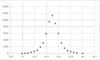
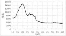
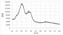
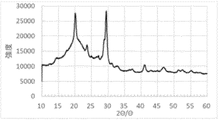
- FIG. 1 It is a flow figure explaining an example of the form of the manufacturing method of this embodiment. It is a figure (X-ray diffraction (XRD) measurement) explaining the calculation method of a crystallography. It is a figure (X-ray diffraction (XRD) measurement) explaining the calculation method of a crystallography. It is an exposure test device for water resistance evaluation. It is the X-ray diffraction (XRD) measurement result of the solid electrolyte (A1) obtained in the step (A) of Example 1. FIG. It is the X-ray diffraction (XRD) measurement result of the solid electrolyte (B1) obtained in the step (B) of Example 1. FIG.
- XRD X-ray diffraction
- the present embodiment an embodiment of the present invention (hereinafter, may be referred to as “the present embodiment”) will be described.
- the numerical values of the upper limit and the lower limit relating to the numerical range of "greater than or equal to”, “less than or equal to”, and “to” are numerical values that can be arbitrarily combined, and the numerical values of the examples are used as the numerical values of the upper limit and the lower limit. You can also do it.
- the present inventors have found the following matters and have completed the present invention.
- the sulfide solid electrolyte has PS 43- as a main skeleton .
- a sulfide solid electrolyte whose peak has been confirmed to be observed at a specific position by XRD measurement has been obtained, further improvement is required in the ionic conductivity and water resistance of the sulfide solid electrolyte obtained thereby. there were.
- Patent Document 1 does not prepare a battery using the obtained sulfide solid electrolyte and evaluate the battery characteristics such as the initial irreversible capacity thereof.
- Patent Document 2 attempts to increase the crystallite diameter, it is around 20 nm as shown in Table 1, and there is still room for improvement. Furthermore, no attention was paid to the P2 S 6 4 - phosphorus ratio, and the battery characteristics such as the initial irreversible capacity were not confirmed.
- Patent Document 3 does not pay attention to the crystallite diameter and the P2 S 6 4 - phosphorus ratio, and does not confirm the battery characteristics such as the initial irreversible capacity.
- the present inventors have diligently studied the sulfide solid electrolyte of Patent Document 1, and the solid electrolytes of Patent Document 2 and Patent Document 3.
- the position of the peak obtained by X-ray diffraction (XRD) measurement of the sulfide solid electrolyte glass ceramics, the crystallite diameter described later, and the P2 S 6 4- phosphorus ratio obtained from the solid 31 P - NMR measurement should be below a specific value. I focused on doing. Ions of sulfide solid electrolyte glass ceramics by having a peak at a specific position, setting the crystallite diameter to a specific value or more, and setting the P2 S 6 4 - phosphorus ratio to a specific value or less.
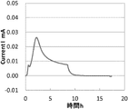
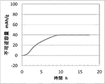
- Irreversible capacity at the time of initial cycle which is one of the battery characteristics required from CV measurement when the battery is made into a battery with improved conductivity and water resistance
- the irreversible capacity is the irreversible capacity unless otherwise specified. It was found that the irreversible capacity (meaning the initial irreversible capacity) at the time of the initial cycle can be suppressed. At the same time, it has been found that the sulfide solid electrolyte glass ceramics can be obtained in high yield by the above-mentioned production method.
- the sulfide solid electrolyte glass ceramics has a peak at a specific position in X-ray diffraction (XRD) measurement, has a specific crystallite diameter, and has a P2 S 6 4- phosphorus ratio obtained from solid 31 P - NMR measurement. Is less than or equal to a certain value, and these characteristics are events that have never been recognized so far. Further, in the method for producing the sulfide solid electrolyte glass ceramics, the ionic conductivity and water resistance of the sulfide solid electrolyte glass ceramics are improved only by changing the method of adding the raw materials conventionally used, and the ionic conductivity and the water resistance can be obtained from the improvement.
- the battery has an excellent irreversible capacity, and this embodiment is an extremely excellent manufacturing method.
- a method for producing a modified sulfide solid electrolyte powder according to the first to thirteenth aspects of the present embodiment will be described.
- the sulfide solid electrolyte glass ceramics according to the first aspect of the present embodiment is In X-ray diffraction (XRD) measurement using CuK ⁇ ray, it has peaks at 20.2 ° and 23.6 °, the crystallite diameter is 30 nm or more, and P 2 S obtained from solid 31 P-NMR measurement. 6 4- Phosphorus ratio is 4.5 mol% or less, which is a sulfide solid electrolyte glass ceramics.
- the determination of the P2S 6 4- phosphorus ratio obtained from the X-ray diffraction (XRD) measurement using CuK ⁇ ray and the solid 31 P - NMR measurement can be carried out by, for example, the method described in Examples.
- the sulfide solid electrolyte of the invention described in Patent Document 1 has a peak at a specific position by X-ray diffraction (XRD) measurement, but the crystallite diameter of the sulfide solid electrolyte is completely different. I'm not paying attention. Furthermore, no attention is paid to the P2 S 6 4- phosphorus ratio obtained from the solid 31 P - NMR measurement. Therefore, it cannot be said that the ionic conductivity and water resistance are sufficiently high. Further, in Patent Document 1, the battery characteristics such as the irreversible capacity of the battery manufactured from the obtained sulfide solid electrolyte have not been studied.
- Patent Document 2 describes the crystallite diameter of the solid electrolyte, it is not sufficiently large and pays no attention to the P2S 6 4- phosphorus ratio obtained from the solid 31 P - NMR measurement. not. Therefore, it cannot be said that the ionic conductivity and water resistance are sufficiently high. Further, in Patent Document 2, the battery characteristics such as the irreversible capacity of the battery manufactured from the obtained sulfide solid electrolyte have not been studied.
- Patent Document 3 does not pay attention to the crystallite diameter of the solid electrolyte and the P2 S 6 4- phosphorus ratio obtained from the solid 31 P - NMR measurement. Therefore, there is room for improvement in ionic conductivity and water resistance. Further, in Patent Document 2, the battery characteristics such as the irreversible capacity of the battery manufactured from the obtained sulfide solid electrolyte have not been studied.
- the crystallite diameter is set to a specific value or more, and P 2S 6 4- phosphorus obtained from solid 31 P - NMR measurement.
- the sulfide solid electrolyte glass ceramics can improve the ionic conductivity and water resistance, and can further suppress the irreversible capacity when made into a battery.
- the reason why the sulfide solid electrolyte glass ceramics according to the first aspect has excellent ionic conductivity and water resistance is not clear, but an increase in crystallite diameter means a decrease in the ratio of grain boundaries. do. Since it is considered that lithium ion diffusion is suppressed at the grain boundaries and moisture easily penetrates, the reduction of the grain boundaries improves the ionic conductivity and water resistance. It is hypothesized that the effect becomes remarkable above a specific crystallite diameter. According to the studies by the inventors, it is known that the P2 S 6 4 - component is easily hydrolyzed.
- the P2 S64 component itself acts as a factor that inhibits the ionic conduction of Li ions and also inhibits the crystal growth of the solid electrolyte, and if this component is large, the crystallite diameter may not be sufficiently large. There is. Therefore, when the phosphorus ratio of P2 S 64 of the sulfide solid electrolyte glass ceramics is 4.5 mol% or less, the water resistance and the ionic conductivity are improved. In addition, the P 2 S 6 4- component traps Li ions in the solid electrolyte and may accelerate the deterioration of the battery, and the phosphorus of the P 2 S 6 4- component of the sulfide solid electrolyte glass ceramics. By setting the ratio to 4.5 mol% or less, it can be expected that the oxidation characteristics of the battery will be improved.
- the irreversible capacity is suppressed and the reason why the battery characteristics are excellent is not clear, but the chemical stability of the solid electrolyte due to the reduction of the crystal grain boundaries is not clear.
- the effect of improving the ionic conductivity and the effect of improving the oxidation characteristics by setting the P2 S 6 4 - phosphorus ratio to a specific value or less, the lithium ion consumed during the initial charge and discharge of the battery The hypothesis is that this is because the amount decreases.
- the P 2 S 6 4- phosphorus ratio can be determined by solid 31 P-NMR, and can be carried out, for example, by the method described in Examples.
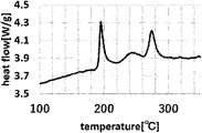
- the sulfide solid electrolyte glass ceramics according to the second aspect of this embodiment is It is a sulfide solid electrolyte glass ceramic having only one exothermic peak having an intensity of 0.15 W / g or more at 310 ° C. or lower in a differential thermal analysis (DTA).
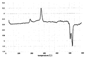
- the differential thermal analysis (DTA) measurement can be performed, for example, by the method described in Examples.
- the sulfide solid electrolyte glass ceramics of the present invention usually have one crystallization exothermic peak below 310 ° C., which is caused by the transition from a high conduction crystal to a low conduction crystal, and suppresses this transition. It is preferable to keep it. In rare cases, it may have two crystallization exothermic peaks below 310 ° C.
- the peak on the low temperature side is related to the precipitation of high conduction crystals, and the fact that this remains means that the growth of high conduction crystals is insufficient, and it is preferable to eliminate it. In summary, in the temperature range of 310 ° C.
- ionic conductivity is improved by controlling so that only one crystallization peak having an intensity of 0.15 W / g or more is provided at 310 ° C. or lower. Therefore, it is preferable.
- the sulfide solid electrolyte glass ceramics according to the third aspect of this embodiment is The ratio of the mole fraction of Li 2S (I Li 2S) to the mole fraction of P 2 S 5 (I P2S 5 ) calculated from the element ratio measured by an inductively coupled plasma (ICP) emission spectroscopic analyzer (I Li 2S / IP2S5 ) is sulfide solid electrolyte glass ceramics having a value of 2.6 or more and 3.3 or less. Measurement by an inductively coupled plasma (ICP) emission spectrophotometer can be performed, for example, by the method described in Examples.
- ICP inductively coupled plasma
- the ratio of the mole fraction of Li 2S (I Li 2S) to the mole fraction of P 2 S 5 (I P2S 5 ) (I Li 2S / I P2S 5 ) is within a specific range.
- the P2 S 6 4 - component which is an impurity of the solid electrolyte, can be reduced, and the ionic conductivity and water resistance are improved.
- the remaining amount of Li 2S is small, which leads to the reduction of free sulfur atoms, the improvement of water resistance, and the suppression of the irreversible capacity when used as a battery.
- the sulfide solid electrolyte glass ceramics according to the fourth aspect of this embodiment is Solid sulfide solid electrolyte A sulfide solid having a phosphorus ratio of P2 S 6 4- obtained from solid 31 P - NMR measurement of the solid electrolyte (B), which is an intermediate for producing glass ceramics, of 15.0 mol% or less. Electrolyte glass ceramics.
- the solid electrolyte (B) is obtained in the step (B) of the eighth aspect described later, and is a production intermediate for producing the sulfide solid electrolyte glass ceramics.
- the P 2 S 6 4- component in the solid electrolyte (B) itself inhibits the ionic conduction of Li ions and also acts as a factor in inhibiting the crystal growth of the solid electrolyte (B).
- the child diameter may not be large enough.
- the P2S64 component is easily hydrolyzed as described above.
- the phosphorus ratio of P2 S 6 4- of the solid electrolyte (B) is 15.0 mol% or less because the ionic conductivity and water resistance are improved.
- the sulfide solid electrolyte glass ceramics according to the fifth aspect of the present embodiment is In the differential thermal analysis (DTA) of the solid electrolyte (B), which is an intermediate for the production of sulfide solid electrolyte glass ceramics, the half-price range of the exothermic peak that first appears at a temperature of 130 ° C or higher during the heating process is 8.0 ° C.
- DTA differential thermal analysis
- the half price width of the exothermic peak that first appears at a temperature of 130 ° C. or higher in the temperature raising process is set to 8.0 ° C. or lower.
- the sulfide solid electrolyte glass ceramics according to the sixth aspect of the present embodiment is A sulfide solid electrolyte glass ceramic containing a lithium atom, a phosphorus atom, a sulfur atom and a halogen atom.
- a lithium atom it is preferable to include a lithium atom, a phosphorus atom, a sulfur atom and a halogen atom because the ionic conductivity and water resistance are further improved.
- the sulfide solid electrolyte glass ceramics according to the seventh aspect of the present embodiment is
- the halogen atom is at least one selected from a chlorine atom, a bromine atom and an iodine atom, which is a sulfide solid electrolyte glass ceramics.
- the halogen atom is at least one selected from chlorine atom, bromine atom and iodine atom because ionic conductivity and water resistance are further improved.
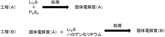
- the method for producing the sulfide solid electrolyte glass ceramics according to the eighth aspect of the present embodiment is The step (A) of treating Li 2 S and P 2 S 5 with at least one selected from stirring, mixing and pulverization to obtain a solid electrolyte (A), and the solid electrolyte (A), Li 2 S and lithium halide
- the sulfide solid electrolyte glass ceramics according to the first to seventh aspects described above can be obtained with high efficiency. That is, the sulfide solid electrolyte glass ceramics having improved ionic conductivity and water resistance can be produced according to the eighth aspect.
- the sulfide solid electrolyte glass ceramics has PS 43- as a main skeleton. However, it also contains subskeletons such as P 2 S 6 4- and P 2 S 7 4- , and in order to improve the ionic conductivity of the sulfide solid electrolyte glass ceramics, the P 2 S 6 4- phosphorus ratio should be used. It is effective to reduce it.
- P2S 74- is known to have extremely poor water resistance, and it is preferable to reduce this component as well.
- the solid electrolyte (A) is obtained in the step (A), and then the solid electrolyte (B) is obtained in the step (B).
- sulfide solids with sub - skeletons such as P2 S 6 4- and P 2 S 7 4- lead to deterioration of the characteristics of sulfide solid electrolyte glass ceramics when synthesized in two stages in this way. It became clear that the content in the electrolyte glass ceramics could be controlled, and the production method according to the eighth aspect was reached.
- the sulfide solid electrolyte glass ceramics contains not only the main skeleton PS 4 3- but also sub-skeletons such as P 2 S 6 4- and P 2 S 7 4- , but the solid electrolyte (A) ) Is the same. However, it is preferable that the subskeleton of the solid electrolyte (A) exists as P2 S 74- . This is because, in step (B), P 2 S 7 4- reacts with Li 2 S and is easily converted into PS 43 , which is the main skeleton.
- the solid electrolyte (A) contains Li 4 P 2 S 7 and the solid electrolyte. A method for producing a sulfide solid electrolyte glass ceramics in which the P2 S 7 4- phosphorus ratio measured by 31 P - NMR in (A) is 20.0 mol% or more has been reached.
- the solid electrolyte (A) further contains P2 S 7 4-, and the phosphorus ratio of P 2 S 7 4- in the solid electrolyte (A) is 20.0 mol% or more. Therefore, the Li 2S added in the step (B) can be sufficiently consumed and the water resistance is improved, which is preferable (Li 2 S is one of the factors for lowering the water resistance). Further, although some P2S 74 - derived from the solid electrolyte (A) remains in the solid electrolyte (B), it does not matter because it almost disappears when it is subsequently heated to form glass ceramics.
- P 2 S 6 4- does not decrease even when heated.
- the P 2 S 7 4- phosphorus ratio and the P 2 S 6 4- phosphorus ratio in the solid electrolyte (A) tend to contradict each other.
- the former is 20.0 mol% or more
- the P 2 S 6 4- phosphorus ratio in the solid electrolyte (A) becomes sufficiently small
- the P 2 S 6 4 -phosphorus ratio in the solid electrolyte (B) also becomes small. Therefore, as described in the fourth aspect, the ionic conductivity and water resistance are improved, and the battery is preferable because the irreversible capacity is suppressed.
- the method for producing the sulfide solid electrolyte glass ceramics according to the tenth aspect of the present embodiment is as follows.
- the solid electrolyte (B) is a method for producing a sulfide solid electrolyte glass ceramic having PS 43- as a main skeleton.
- the solid electrolyte (B) has PS 43- as the main skeleton because the ionic conductivity and water resistance are improved.
- the method for producing the sulfide solid electrolyte glass ceramics according to the eleventh aspect of the present embodiment is as follows.
- the solid electrolyte (B) is an amorphous sulfide solid electrolyte
- the method for producing the sulfide solid electrolyte glass ceramics according to the twelfth aspect of the present embodiment is as follows.
- This is a method for producing solid electrolyte glass ceramics.
- the amorphous solid electrolyte (B) is heated to a glass ceramic at a temperature in the above region to obtain ionic conductivity and ionic conductivity. It is preferable because the water resistance is greatly improved.
- the method for producing the sulfide solid electrolyte glass ceramics according to the thirteenth aspect of the present embodiment is A method for producing a sulfide solid electrolyte glass ceramic, which comprises further heating the solid electrolyte (A).
- the amorphous solid electrolyte (A) it is preferable to heat the amorphous solid electrolyte (A) to form a glass ceramic because the ionic conductivity and water resistance of the sulfide solid electrolyte glass ceramics of the present invention are significantly improved.
- the amorphous solid electrolyte (A) containing P 2 S 7 4- is obtained and then heated or the like, the P 2 S 7 4- phosphorus ratio is further improved, and the P 2 S 6 4- phosphorus ratio is accordingly increased. Is reduced. It is preferable because the low P2S 6 4 - phosphorus ratio can be maintained or reduced even through the subsequent step (B) and the ionic conductivity is further improved.
- the battery using the sulfide solid electrolyte glass ceramics according to the fourteenth aspect of the present embodiment is It is a battery using the sulfide solid electrolyte glass ceramics according to any one of 1 to 7 of this embodiment.
- the ionic conductivity and water resistance are significantly improved, and the irreversible capacity is suppressed.
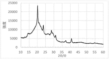
- the sulfide solid electrolyte glass ceramics of the present embodiment are preferably obtained by heating an amorphous sulfide solid electrolyte, which will be described later, and are measured by X-ray diffraction (XRD) using CuK ⁇ rays. It is required to have peaks at .2 ° and 23.6 ° and a crystallite diameter of 30 nm or more. The peak position and crystallite diameter by X-ray diffraction (XRD) measurement using CuK ⁇ rays can be determined, for example, by the method described in Examples.
- the crystal structure of the sulfide solid electrolyte glass ceramics of the present embodiment is preferably a thiolithicon region type II crystal structure in that higher ionic conductivity can be obtained.
- the "thio-lithicon region II type crystal structure” is a Li 4-x Ge 1-x P x S4 system thio-lithicon region II (thio-LISION Region II) type crystal structure, Li 4 -x Ge 1-x . It is shown that it has one of the crystal structures similar to the PxS4 system thio- LISION Region II type. Further, the sulfide solid electrolyte glass ceramics of the present embodiment may have the above-mentioned thiolycycon region type II crystal structure or may have as the main crystal, but may have higher ionic conductivity. From the viewpoint of obtaining, it is preferable to have it as a main crystal.
- the sulfide solid electrolyte glass ceramics of the present embodiment preferably do not contain crystalline Li 3 PS 4 ( ⁇ -Li 3 PS 4 ) from the viewpoint of obtaining higher ionic conductivity.
- Li 7 P 3 S 11 crystal structure 15.3 °, 25.2 °, 29.6 °, 31.0 °
- Li 4-x Ge 1-x P x S4 system thioli Li 4-x Ge 1-x P x S4 system thioli .
- the sulfide solid electrolyte glass ceramics of the present embodiment preferably do not contain crystalline Li 3 PS 4 ( ⁇ -Li 3 PS 4 ).
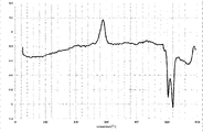
- 9 and 13 show an example of X-ray diffraction measurement of the sulfide solid electrolyte glass ceramics of the present embodiment.
- composition formulas Li 7-x P 1- y S y S 6 and Li 7 + x P 1-y S y S 6 having the structural skeleton of the above-mentioned Li 7 PS 6 and having a part of P substituted with Si (Li 7-x P 1-y S y S 6 ).
- the crystal structure represented by the composition formula Li 7-x-2y PS 6-xy Cl x (0.8 ⁇ x ⁇ 1.7, 0 ⁇ y ⁇ -0.25 x + 0.5) is preferably cubic.
- 2 ⁇ 15.5 °, 18.0 °, 25.0 °, 30.0 °, 31.4 °, 45.3 °, 47. It has peaks appearing at 0 ° and 52.0 °.
- the crystal structure represented by the composition formula Li 7-x PS 6-x Ha x (Ha is Cl or Br, x is preferably 0.2 to 1.8) is preferably a cubic crystal and is a CuK ⁇ ray.
- the crystallite diameter of the sulfide solid electrolyte glass ceramics of the present embodiment is required to be 30 nm or more. From the viewpoint of improving ionic conductivity and water resistance, it is preferably 33 nm or more, more preferably 35 nm or more, further preferably 40 nm or more, further preferably 70 nm or more, and even more preferably 80 nm.
- the above is more excellent and preferable, and as will be described later, by crystallization after the step (A), the crystallite diameter of the sulfide solid electrolyte glass ceramics can be further increased. In such a case, the crystallite diameter can be further increased. It is even more preferable that it is 90 nm or more.
- the upper limit is not particularly limited, but is preferably 300 nm or less, more preferably 250 nm or less, and more preferably 200 nm or less from the viewpoint of ease of manufacturing, procurement, and manufacturing of batteries and the like. Is more preferable, 150 nm or less is further preferable, and 130 nm or less is more excellent and preferable.
- the sulfide solid electrolyte glass ceramics of the present embodiment requires that the P2S 6 4- phosphorus ratio determined from the solid 31 P - NMR measurement be 4.5 mol% or less. In order to improve ionic conductivity and water resistance and suppress irreversible capacity, it is preferably 4.0 mol% or less, more preferably 3.0 mol% or less, and 2.5 mol% or less. It is more preferably 2.2 mol% or less, and more preferably 2.0 mol% or less. The smaller the P2 S 6 4 - phosphorus ratio is, the more preferable it is, and the lower limit is not particularly limited, and it may be substantially 0 mol% or more. Substantially means that 0 mol% also includes below the detection limit.
- the smaller the P2 S7 4- phosphorus ratio is preferably from the viewpoint of the ionic conductivity of the sulfide solid electrolyte, preferably 20.0% or less. It is more preferably 9.0% or less, further preferably 8.0% or less, and the lower limit is preferably close to 0%.
- the sulfide solid electrolyte glass ceramics of the present embodiment preferably has only one exothermic peak having an intensity of 0.15 W / g or more at 310 ° C. or lower because the ionic conductivity is improved. It is more preferably 0.20 W / g or more, and further preferably 0.25 W / g or more.
- the upper limit is preferably 5.0 W / g or less, more preferably 3.0 W / g or less, further preferably 1.0 W / g or less, and 0.80 W / g or less. Is even more preferable.
- the exothermic peak of the sulfide solid electrolyte glass ceramics of the present embodiment is preferably 200 ° C. or higher and 350 ° C. or lower, more preferably 230 ° C. or higher and 320 ° C. or lower, and 250 ° C. or higher and 300 ° C. or lower. More preferred.
- the sulfide solid electrolyte glass ceramics of the present embodiment have a mole fraction of Li 2S ( I Li 2S ) and a mole fraction of P 2 S 5 calculated from the element ratio measured by an inductively coupled plasma (ICP) emission spectroscopic analyzer.
- ICP inductively coupled plasma
- the ratio (I Li2S / I P2S5 ) of the fraction fraction (I P2S5 ) is 2.60 or more and 3.30 or less
- the irreversible capacity when used as a battery is increased in order to improve ionic conductivity and water resistance. It is preferable to suppress it, and it is more preferably 2.70 or more and 3.20 or less, and further preferably 2.90 or more and 3.10 or less from the viewpoint of improving ionic conductivity and water resistance.
- the measurement by the ICP emission spectrophotometer can be measured by, for example, the method described in Examples.
- the sulfide solid electrolyte glass ceramics of the present embodiment preferably contain a lithium atom, a phosphorus atom, a sulfur atom and a halogen atom.
- the "sulfide solid electrolyte” is an electrolyte that maintains a solid at 25 ° C. under a nitrogen atmosphere, and contains lithium atoms, sulfur atoms, and phosphorus atoms, and has ionic conductivity due to the lithium atoms. It is a solid electrolyte. It is preferable to further contain a halogen atom if necessary.
- the halogen atom is at least one selected from a chlorine atom, a bromine atom and an iodine atom.
- a bromine atom or an iodine atom When only one type of halogen atom is contained, it is preferably a bromine atom or an iodine atom, and more preferably an iodine atom.
- the combination of chlorine atom and bromine atom, the combination of chlorine atom and bromine atom, or the combination of bromine atom and iodine atom is preferable, and the combination of bromine atom and iodine atom is more preferable. ..
- the ionic conductivity and water resistance can be further improved, and the irreversible capacity of the battery can be suppressed.
- the term "main skeleton" means that the phosphorus ratio of PS 43-unit (PS 4 3 - phosphorus ratio) exceeds 50.0%, and the high ionic conduction of the sulfide solid electrolyte.
- the PS 43 - phosphorus ratio is preferably 60.0 % or more, more preferably 70.0% or more, further preferably 80.0% or more, and the upper limit. The value is not particularly limited and should be close to 100%.
- the ratio of PS 4 3- unit (PS 4 3- phosphorus ratio), the proportion of P 2 S 7 4- unit (P 2 S 7 4- phosphorus ratio) and P 2 S 6 4- unit.
- the ratio (P 2 S 6 4- phosphorus ratio) is obtained by measuring the 31 P MAS NMR spectrum (solid 31 P NMR spectrum) and separating the waveforms, respectively, PS 43- unit and P 2 S 7 4- . It means the ratio of the peak area of the unit and P2 S 6 4 - unit to the whole.
- the detailed conditions for measuring the solid 31 P NMR spectrum are not particularly limited, but the measurement may be performed based on, for example, various conditions described in Examples.
- the "sulfide solid electrolyte” includes both a crystalline sulfide solid electrolyte having a crystal structure and an amorphous sulfide solid electrolyte.
- the crystalline sulfide solid electrolyte is a sulfide solid electrolyte in which a peak derived from the sulfide solid electrolyte is observed in the X-ray diffraction pattern in the X-ray diffraction measurement, and the sulfide solid in these. It is a material regardless of the presence or absence of a peak derived from the raw material of the electrolyte.
- the crystalline sulfide solid electrolyte contains a crystal structure derived from the sulfide solid electrolyte, and even if a part of the crystal structure is derived from the sulfide solid electrolyte, all of the crystal structure becomes the sulfide solid electrolyte. It may be a derived crystal structure.
- the crystalline sulfide solid electrolyte may contain an amorphous sulfide solid electrolyte as long as it has the above-mentioned X-ray diffraction pattern, and is amorphous. It does not have to contain the sulfide solid electrolyte.
- the crystalline sulfide solid electrolyte includes so-called glass ceramics obtained by heating the amorphous sulfide solid electrolyte to a crystallization temperature or higher.
- the sulfide solid electrolyte glass ceramics of the present embodiment is a crystalline sulfide solid electrolyte containing an amorphous component.
- a peak of the crystal structure derived from the sulfide solid electrolyte and a halo pattern derived from the amorphous sulfide solid electrolyte are observed in the X-ray diffraction pattern in the X-ray diffraction measurement. It is a sulfide solid electrolyte.
- the amorphous sulfide solid electrolyte is a halo pattern in which the X-ray diffraction pattern is substantially not observed in the X-ray diffraction measurement, and is derived from the raw material of the sulfide solid electrolyte. It means that the presence or absence of the peak of the above, or the presence or absence of a small amount of crystals inevitably generated by the operation when isolating the amorphous sulfide solid electrolyte is irrelevant.
- the shape of the sulfide solid electrolyte glass ceramics of the present embodiment is not particularly limited, and examples thereof include particles.
- the average particle size ( D50 ) of the sulfide solid electrolyte glass ceramics of the present embodiment in the form of particles can be exemplified in the range of 0.01 ⁇ m to 500 ⁇ m and 0.1 to 200 ⁇ m, for example.
- the average particle size (D 50 ) can be measured by, for example, a laser diffraction / scattering type particle size distribution measuring device (for example, LA-950V2 model LA-950W2 manufactured by HORIBA).
- the ionic conductivity of the sulfide solid electrolyte glass ceramics of the present embodiment obtained by the production method of the present embodiment is extremely high due to the high PS 43- phosphorus ratio, and is usually 0.01 mS / cm or more. Can be. It is preferably 4.50 mS / cm or more, preferably 4.80 mS / cm or more, and preferably 5.00 mS / cm or more.
- the method for producing the sulfide solid electrolyte glass ceramics of the present embodiment is as shown in FIG.
- the production method of the present embodiment is preferable because the above-mentioned sulfide solid electrolyte glass ceramics capable of improving ionic conductivity and water resistance and suppressing irreversible capacity when used as a battery can be obtained.
- the step (A) of the present embodiment requires that Li 2 S and P 2 S 5 are treated with at least one selected from stirring, mixing and pulverization described later to obtain a solid electrolyte (A).
- the solid electrolyte (A), Li 2S and lithium halide obtained in the step (A) are treated with at least one selected from stirring, mixing and pulverization described later, and the solid electrolyte is treated. It is necessary to obtain (B).
- the solid electrolyte (A) may be taken out after the completion of the step (A), and Li 2S and lithium halide may be added to the obtained solid electrolyte (A) for treatment, or the step (A) may be performed.
- the treatment of the step (A) and the step (B) of the present embodiment needs to be at least one selected from stirring, mixing and pulverization.
- Stirring, mixing and pulverization may be performed alone or in combination, but pulverization is preferable from the viewpoint of setting the particle size of the sulfide solid electrolyte in the range described later.
- the processes of the steps (A) and (B) may be the same or different, but they are preferably the same, and from the viewpoint of not complicating the manufacturing process, they are continuously used using the same processing apparatus. It is more preferable to carry out the process.
- the processing of this embodiment can be performed using a mixer, a stirrer, a crusher, or the like. This is because the raw materials can be mixed even if a stirrer is used, and the raw materials are crushed in the crusher, but the mixing also occurs at the same time.
- Examples of the stirrer and the mixer include a mechanical stirring type mixer capable of stirring (mixing by stirring or stirring and mixing) by providing a stirring blade in the reaction vessel.
- Examples of the mechanical stirring type mixer include a high-speed stirring type mixer and a double-arm type mixer.
- Examples of the high-speed stirring type mixer include a vertical axis rotary type mixer and a horizontal axis rotary type mixer, and either type of mixer may be used.
- the shapes of the stirring blades used in the mechanical stirring type mixer include blade type, arm type, anchor type, paddle type, full zone type, ribbon type, multi-stage blade type, double arm type, excavator type, and biaxial blade type.
- Examples thereof include a flat blade type and a C type blade type, and from the viewpoint of accelerating the reaction of raw materials more efficiently, a shovel type, a flat blade type, a C type blade type, an anchor type, a paddle type, a full zone type and the like are preferable.
- Anchor type, paddle type and full zone type are more preferable.
- the rotation speed of the stirring blade may be appropriately adjusted according to the capacity of the fluid in the reaction vessel, the temperature, the shape of the stirring blade, etc., and is not particularly limited, but is usually 5 rpm or more and 400 rpm or less. From the viewpoint of accelerating the reaction of the raw material more efficiently, it is preferably 10 rpm or more and 300 rpm or less, more preferably 15 rpm or more and 250 rpm or less, and further preferably 20 rpm or more and 200 rpm or less.
- the temperature conditions for mixing using a mixer are not particularly limited, and are, for example, usually ⁇ 30 to 120 ° C., preferably ⁇ 10 to 100 ° C., more preferably 0 to 80 ° C., still more preferably 10 to 60 ° C. Is.
- the mixing time is usually 0.1 to 500 hours, preferably 1 to 450 hours, more preferably 10 to 425 hours, still more preferably 20 to 400, from the viewpoint of making the dispersed state of the raw materials more uniform and promoting the reaction. The time, more preferably 30 to 375 hours.
- the method of performing mixing accompanied by pulverization using a pulverizer is a method conventionally adopted as a mechanical milling method.
- the crusher for example, a medium-type crusher using a crushing medium can be used.
- the medium-type crusher is roughly classified into a container-driven crusher and a medium-stirring crusher.
- Examples of the container-driven crusher include a stirring tank, a crushing tank, a ball mill combining these, a bead mill, and the like.
- the medium stirring type crusher includes an impact type crusher such as a cutter mill, a hammer mill, and a pin mill; a tower type crusher such as a tower mill; a stirring tank type crusher such as an attritor, an aquamizer, and a sand grinder; Distribution tank type crushers such as pearl mills; distribution tube type crushers; general type crushers such as coball mills; continuous dynamic type crushers; various crushers such as single-screw or multi-screw kneaders.
- a ball mill or a bead mill exemplified as a container-driven crusher is preferable in consideration of ease of adjusting the particle size of the obtained sulfide.
- crushers can be appropriately selected according to a desired scale and the like, and if the scale is relatively small, a container-driven crusher such as a ball mill or a bead mill can be used, and a large-scale or mass-produced crusher can be used. In the case of chemical conversion, another type of crusher may be used.
- a wet pulverizer capable of dealing with wet pulverization is preferable.
- the wet crusher include a wet bead mill, a wet ball mill, a wet vibration mill, etc., and the conditions of the crushing operation can be freely adjusted, and the beads can be easily crushed with a smaller particle size.
- a dry medium crusher such as a dry bead mill, a dry ball mill, a dry planetary ball mill, and a dry vibration mill
- a dry crusher such as a dry non-medium crusher such as a jet mill
- a circulation type crusher capable of circulating operation to circulate as needed can also be used. Specific examples thereof include a crusher that circulates between a crusher (crushing mixer) that crushes the slurry and a temperature holding tank (reaction vessel).
- the size of the beads and balls used in the ball mill and the bead mill may be appropriately selected according to a desired particle size, processing amount, etc.
- the diameter of the beads is usually 0.05 mm ⁇ or more, preferably 0.1 mm ⁇ or more. It is more preferably 0.3 mm ⁇ or more, and the upper limit is usually 5.0 mm ⁇ or less, preferably 3.0 mm ⁇ or less, and more preferably 2.0 mm ⁇ or less.
- the diameter of the ball is usually 2.0 mm ⁇ or more, preferably 2.5 mm ⁇ or more, more preferably 3.0 mm ⁇ or more, and the upper limit is usually 30.0 mm ⁇ or less, preferably 20.0 mm ⁇ or less, more preferably 15.0 mm ⁇ or less.
- the material include metals such as stainless steel, chrome steel and tungsten carbide; ceramics such as zirconia and silicon nitride; and minerals such as agate.
- the number of rotations varies depending on the scale of processing, so it cannot be said unconditionally, but it is usually 10 rpm or more, preferably 20 rpm or more, more preferably 50 rpm or more, and the upper limit is It is usually 1,000 rpm or less, preferably 900 rpm or less, more preferably 800 rpm or less, still more preferably 700 rpm or less.
- the crushing time in this case cannot be unconditionally determined because it varies depending on the scale of the treatment, but is usually 5 hours or more, preferably 10 hours or more, more preferably 20 hours or more, still more preferably 30 hours or more.
- the upper limit is usually 300 hours or less, preferably 200 hours or less, and more preferably 100 hours or less.
- the rotation speed of the rotor By selecting the size and material of the medium (beads, balls) to be used, the rotation speed of the rotor, the time, etc., mixing, stirring, pulverization, and a combination of these processes can be performed, and the obtained sulfide can be obtained.
- the particle size and the like can be adjusted.
- solvent In the above mixing, a solvent can be added to the above raw materials and mixed.
- various solvents widely referred to as organic solvents and the like can be used.
- a solvent conventionally used in the production of solid electrolytes can be widely adopted, and for example, hydrocarbons such as an aliphatic hydrocarbon solvent, an alicyclic hydrocarbon solvent, and an aromatic hydrocarbon solvent can be widely adopted. Examples include solvents.
- Examples of the aliphatic hydrocarbon include hexane, pentane, 2-ethylhexane, heptane, octane, decane, undecane, dodecane, tridecane and the like
- examples of the alicyclic hydrocarbon include cyclohexane and methylcyclohexane.
- Examples of the aromatic hydrocarbon solvent include benzene, toluene, xylene, mesitylene, ethylbenzene, tert-butylbenzene, trifluoromethylbenzene, nitrobenzene and the like.
- a solvent containing a hetero element such as a carbon element and an element other than a hydrogen element, for example, a nitrogen element, an oxygen element, a sulfur element, and a halogen element
- a solvent for example, an ether solvent, an ester solvent, an alcohol solvent, an aldehyde solvent, and a ketone solvent, which contain an oxygen element as a hetero element, are also preferable.
- ether solvent examples include dimethyl ether, diethyl ether, tert-butyl methyl ether, dimethoxymethane, dimethoxy ethane, diethylene glycol dimethyl ether (digrim), triethylene oxide glycol dimethyl ether (triglycer), and aliphatic ethers such as diethylene glycol and triethylene glycol; Alicyclic ethers such as ethylene oxide, propylene oxide, tetrahydrofuran, tetrahydropyran, dimethoxytetratetratetratetramethyl ether, dioxane; heterocyclic ethers such as furan, benzofuran and benzopyran; methylphenyl ether (anisole), ethylphenyl ether, dibenzyl Aromatic ethers such as ether and diphenyl ether are preferably mentioned.
- ester solvent examples include methyl formate, ethyl formate, methyl acetate, ethyl acetate, propyl acetate, isopropyl acetate; methyl propionate, ethyl propionate, dimethyl oxalate, diethyl oxalate, dimethyl malonate, diethyl malonate, and succinic acid.
- Alicyclic esters such as dimethyl and diethyl succinate; alicyclic esters such as methyl cyclohexanecarboxylate, ethyl cyclohexanecarboxylate, dimethyl cyclohexanedicarboxylic acid; methyl pyridinecarboxylate, methyl pyrimidinecarboxylate, acetlactone, propiolactone, butyrolactone , Valerolactone and the like; aromatic esters such as methyl benzoate, ethyl benzoate, dimethylphthalate, diethylphthalate, butylbenzylphthalate, dicyclohexylphthalate, trimethyltrimethylate and triethyl trimellitate are preferable.
- alcohol solvents such as ethanol and butanol
- aldehyde solvents such as formaldehyde, acetaldehyde and dimethylformamide
- ketone solvents such as acetone and methyl ethyl ketone
- the solvent containing a nitrogen element as a hetero element include a solvent having a group containing a nitrogen element such as an amino group, an amide group, a nitro group and a nitrile group. These can also be used as a complexing agent for forming a solid electrolyte into a complexing agent.
- examples of the solvent having an amino group include aliphatic amines such as ethylenediamine, diaminopropane, dimethylethylenediamine, diethylethylenediamine, dimethyldiaminopropane, tetramethyldiaminomethane, tetramethylethylenediamine (TMEDA) and tetramethyldiaminopropane (TMPDA); Alicyclic amines such as cyclopropanediamine, cyclohexanediamine, bisaminomethylcyclohexane; heterocyclic amines such as isophoronediamine, piperazine, dipiperidylpropane, dimethylpiperazin; phenyldiamine, tolylene diamine, naphthalenediamine, methylphenylenediamine, Aromatic amines such as dimethylnaphthalenediamine, dimethylphenylenediamine, tetramethylphenylenediamine, and tetramethylna
- the solvent containing a halogen element as a hetero element include dichloromethane, chlorobenzene, trifluoromethylbenzene, chlorobenzene, chlorotoluene, bromobenzene and the like.
- the solvent containing a sulfur element dimethyl sulfoxide, carbon disulfide and the like are preferably mentioned.
- the amount of the solvent used is preferably 100 mL or more, more preferably 500 mL or more, still more preferably 1 L or more, still more preferably 2 L or more, still more preferably 2 L or more, based on 1 kg of the total amount of the raw materials. It is 4 L or more, and the upper limit is preferably 50 L or less, more preferably 20 L or less, still more preferably 15 L or less, still more preferably 12 L or less. When the amount of the solvent used is within the above range, the raw materials can be efficiently reacted.
- mixing When mixing is performed using a solvent, it may include drying the fluid (usually slurry) obtained by mixing after mixing.
- the complexing agent When the complexing agent is used as the solvent, the complexing agent is removed from the complex containing the complexing agent, and when the complexing agent and the solvent are used in combination, the complexing agent is formed from the complex containing the complexing agent.
- a sulfide can be obtained by removing the agent and removing the solvent, or by removing the solvent when a solvent other than the complexing agent is used.
- the obtained sulfide has a structure possessed by a solid electrolyte such as PS 43- unit , and exhibits ionic conductivity due to an alkali metal element such as a lithium element and a sodium element.
- Drying can be performed on the fluid obtained by mixing at a temperature depending on the type of solvent. For example, it can be carried out at a temperature equal to or higher than the boiling point of the complexing agent. Further, it is usually dried under reduced pressure at 5 to 100 ° C., preferably 10 to 85 ° C., more preferably 15 to 70 ° C., still more preferably about room temperature (23 ° C.) (for example, about room temperature ⁇ 5 ° C.) using a vacuum pump or the like. It can be carried out by (vacuum drying) to volatilize the complexing agent and, if necessary, the solvent used.
- Drying may be performed by filtering the fluid using a glass filter or the like, solid-liquid separation by decantation, or solid-liquid separation using a centrifuge or the like.
- a solvent other than the complexing agent is used, sulfide is obtained by solid-liquid separation.
- the complexing agent incorporated into the complex may be removed by performing solid-liquid separation and then drying under the above temperature conditions.
- the fluid is transferred to a container, and the supernatant is obtained after the sulfide (or the complex (which may also be referred to as a precursor of sulfide) if it contains a complexing agent) is precipitated.
- the sulfide or the complex (which may also be referred to as a precursor of sulfide) if it contains a complexing agent) is precipitated.
- Decantation for removing complexing agents and solvents, and filtration using, for example, a glass filter having a pore size of about 10 to 200 ⁇ m, preferably 20 to 150 ⁇ m is easy.
- the drying may be performed after the mixing and before the hydrogen treatment described later, or after the hydrogen treatment.
- Li 2 S and P 2 S 5 In the production method of this embodiment, it is necessary to use Li 2 S (lithium sulfide) and P 2 S 5 (diphosphorus pentasulfide).
- the Li 2S used in this embodiment is preferably particles.
- the average particle size ( D 50 ) of the Li 2S particles is preferably 10 ⁇ m or more and 2000 ⁇ m or less, more preferably 30 ⁇ m or more and 1500 ⁇ m or less, and further preferably 50 ⁇ m or more and 1000 ⁇ m or less.
- the average particle size (D 50 ) is the particle size at which the particles with the smallest particle size are sequentially integrated to reach 50% of the total when the particle size distribution integration curve is drawn, and the volume distribution is For example, it is an average particle size that can be measured by using a laser diffraction / scattering type particle size distribution measuring device.
- P 2 S 5 those having the same average particle size as the Li 2 S particles are preferable, that is, those having the same range as the average particle size of the Li 2 S particles are preferable.
- Li 2 S is added in step (A) and step (B), and P 2 S 5 is added in step (A).
- step ( A ) 1.00 mol of Li 2S from the viewpoint of optimizing the content of P2 S 74 in the solid electrolyte (A) and preparing a sulfide solid electrolyte glass ceramic having high ionic conductivity.
- it is preferable to use 0.34 mol or more of P 2 S 5 more preferably 0.38 mol or more, further preferably 0.40 mol or more, and preferably 0.70 mol or less. It is more preferable to use 0.60 mol or less, and further preferably 0.55 mol or less.
- the sulfide solid electrolyte glass ceramics have PS 43 as the main skeleton, and P 2 S 64 in the sulfide solid electrolyte.
- P 2 S 64 in the sulfide solid electrolyte.
- Li 2S is added at least in step (A) and step (B). From the viewpoint of reducing the P 2 S 6 4- phosphorus ratio in the sulfide solid electrolyte and achieving high ionic conductivity, 1.00 mol of Li 2 S used in step (A) is compared with that of step (B). Li 2S is preferably used in an amount of 0.10 mol or more, more preferably 0.20 mol or more, further preferably 0.25 mol or more, preferably 0.80 mol or less, and 0.70 mol or less. It is more preferable to use less than a molar amount, and even more preferably 0.65 mol or less.
- Li 2 S and P 2 S 5 commercially available commercially available ones can be used, but those prepared by the method adjusted by the method described in Examples may also be used.
- the purity of Li 2 S is preferably 95% by mass or more, more preferably 98% by mass or more, and P 2 S 5 is P 4 from the viewpoint of improving the ionic conductivity of the sulfide solid electrolyte glass ceramics. From the viewpoint of improving the ionic conductivity of the sulfide solid electrolyte based on S10, the purity is preferably 95% by mass or more, and more preferably 98% by mass or more.
- lithium halide in order to introduce a halogen atom into the sulfide solid electrolyte from the viewpoint of obtaining the sulfide solid electrolyte glass ceramics having high ionic conductivity, it is necessary to further add lithium halide in the step (B).
- the lithium halide at least one selected from lithium chloride, lithium bromide and lithium iodide is more preferable, and a combination of lithium chloride and lithium bromide, or a combination of lithium bromide and lithium iodide is further preferable.
- the amount of lithium halide used may be any as long as it satisfies the preferable compounding ratio (molar ratio) of the above-mentioned lithium atom, sulfur atom, phosphorus atom and halogen atom.
- the solid electrolyte (A) is a solid electrolyte obtained in the step ( A), and is preferably a sulfide solid electrolyte having PS 4 3- or P2 S 7 4- as the main skeleton, preferably PS 4 3- . It is more preferable that the sulfide solid electrolyte has the main skeleton.
- the term "main skeleton" means that the phosphorus ratio (PS 43- phosphorus ratio) of PS 43 - units exceeds 50.0 %, and the high ionic conduction of the sulfide solid electrolyte.
- the PS 43 - division is preferably 60.0 % or more, more preferably 70.0% or more, further preferably 80.0% or more, and the upper limit.
- the value is not particularly limited and should be close to 100%, but is preferably 99.5% or less, more preferably 98.0% or less, from the viewpoint of achieving both ease of manufacture and ionic conductivity. It is more preferably 95.0% or less.
- the solid electrolyte (A) preferably contains P2 S 7 4- . Further, Li 2 S and P 2 S 5 used as raw materials in a small amount, PS 4 3 3 which is the target product, and P 2 S 6 4 4 may be further contained. Of these, when the content of P 2 S 6 4- in the sulfide solid electrolyte increases, it leads to a decrease in ionic conductivity, so it is preferable to reduce the content.
- step (B) Li 2S and lithium halide are further added to the solid electrolyte (A) containing Li 4 P 2 S 7 to obtain a sulfide solid electrolyte, which is contained in the sulfide solid electrolyte glass ceramics.
- the P 2 S 6 4- phosphorus ratio can be reduced and the ionic conductivity is improved. Therefore, from the viewpoint of improving the ionic conductivity of the sulfide solid electrolyte glass ceramics, the P2 S7 4 - phosphorus ratio measured by 31 P - NMR in the solid electrolyte (A) is the total amount of the solid electrolyte (A).
- the standard is 20.0 mol% or more, more preferably 30.0 mol% or more, further preferably 35.0 mol% or more, and the upper limit is not particularly limited, but the step. Since PS 43- is generated when the treatment of (A) is performed, it is preferably 95.0 mol% or less, more preferably 90.0 mol% or less, and 80.0 mol% or less. Is more preferable.
- the solid electrolyte (A) may be an amorphous sulfide solid electrolyte or a crystalline sulfide solid electrolyte, but if it is a crystalline sulfide solid electrolyte, the crystallite diameter of the sulfide solid electrolyte glass ceramics may be large. It is preferable because it becomes large.
- Solid electrolyte (B) The solid electrolyte (B) obtained by the present embodiment is a product of the step (B), is a production intermediate of the sulfide solid electrolyte glass ceramics, and contains a lithium atom, a sulfur atom, and a phosphorus atom. It is preferable to use PS 43- as the main skeleton.
- the solid electrolyte (B) may be an amorphous sulfide solid electrolyte or a crystalline sulfide solid electrolyte. If it is an amorphous sulfide solid electrolyte, it can be made into a sulfide solid electrolyte glass ceramics by heating (crystallization) described later. When it is a crystalline sulfide solid electrolyte, it can be used as a sulfide solid electrolyte glass ceramics, but it can also be further heated to proceed with crystallization.
- the solid electrolyte (B) is preferably amorphous.
- the solid electrolyte (B) contains a halogen atom, and typical ones containing a halogen atom include, for example, Li 2 SP 2 S 5 -LiI, Li 2 SP 2 S 5 -LiCl, Li 2 .
- Solid electrolytes containing, for example, Li 2 S-P 2 S 5 -Li 2 O-LiI, Li 2 S-SiS 2 -P 2 S 5 -Li I, etc. are preferable.
- a solid electrolyte composed of lithium sulfide, phosphorus sulfide and lithium halide, such as 5 -LiI-LiBr, is preferable.
- the type of atom constituting the solid electrolyte (B) can be confirmed by, for example, an ICP emission spectrophotometer.
- the P2 S 6 4- phosphorus ratio obtained from the solid 31 P - NMR measurement of the solid electrolyte (B), which is a production intermediate is 15.0 mol% or less. It is preferable to improve ionic conductivity and water resistance, more preferably 10.0 mol% or less, and further preferably 7.0 mol% or less from the viewpoint of improving ionic conductivity and water resistance.
- the lower limit is not particularly limited because it is preferable not to contain P 2 S 6 4- in order to improve ionic conductivity and water resistance and to suppress the irreversible capacity of the battery.
- the solid electrolyte (B) obtained in the present embodiment has at least Li 2 SP 2 S 5, the molar ratio of Li 2 S to P 2 S 5 obtains higher ionic conductivity. From the viewpoint, 65 to 85:15 to 35 is preferable, 70 to 80:20 to 30 is more preferable, and 72 to 78:22 to 28 is further preferable.
- the solid electrolyte (B) obtained in the present embodiment is, for example, Li 2 SP 2 S 5 -Li I-Li Br
- the total content of Li 2 S and P 2 S 5 is 60 to 95 mol. % Is preferred, 65-90 mol% is more preferred, and 70-85 mol% is even more preferred.
- the ratio of lithium bromide to the total of lithium bromide and lithium iodide is preferably 1 to 99 mol%, more preferably 20 to 90 mol%, further preferably 40 to 80 mol%, and even more preferably 50 to 70 mol. % Is particularly preferable.
- the compounding ratio (molar ratio) of the lithium atom, the sulfur atom, the phosphorus atom and the halogen atom is 1.0 to 1.8: 1.0 to 2.0: 0. .1 to 0.8: 0.01 to 0.6 is preferable, and 1.1 to 1.7: 1.2 to 1.8: 0.2 to 0.6: 0.05 to 0.5 is more preferable. It is preferable, and more preferably 1.2 to 1.6: 1.3 to 1.7: 0.25 to 0.5: 0.08 to 0.4.
- the compounding ratio (molar ratio) of lithium atom, sulfur atom, phosphorus atom, bromine, and iodine is 1.0 to 1.8: 1.0 to 2. 0: 0.1 to 0.8: 0.01 to 0.3: 0.01 to 0.3 is preferable, and 1.1 to 1.7: 1.2 to 1.8: 0.2 to 0. 6: 0.02 to 0.25: 0.02 to 0.25 is more preferable, 1.2 to 1.6: 1.3 to 1.7: 0.25 to 0.5: 0.03 to 0.
- the shape of the solid electrolyte (B) is not particularly limited, and examples thereof include particles.
- the average particle size (D 50 ) of the particulate solid electrolyte (B) can be exemplified in the range of 0.01 ⁇ m to 500 ⁇ m and 0.1 to 200 ⁇ m, for example.
- the exothermic peak of the sulfide solid electrolyte glass ceramics of the present embodiment is preferably 120 ° C. or higher and 300 ° C. or lower, more preferably 150 ° C. or higher and 250 ° C. or lower, and 170 ° C. or higher and 220 ° C. or lower. More preferred.
- the sulfide solid electrolyte glass ceramics of the present embodiment has a half-price width of the exothermic peak that first appears at a temperature of 130 ° C. or higher in the differential thermal analysis (DTA) of the solid electrolyte (B), which is a production intermediate.
- DTA differential thermal analysis
- the amorphous solid electrolyte (A) and the amorphous solid electrolyte (B) it is preferable to further heat the amorphous solid electrolyte (A) and the amorphous solid electrolyte (B).
- the amorphous solid electrolyte (A) or the amorphous solid electrolyte (B) may be obtained and then heated.
- the solid electrolyte (A) obtained in the step (A) may be heated to obtain a crystalline solid electrolyte (A) and then used as a raw material in the step (B), or may be used as a raw material in the step (B).
- the amorphous solid electrolyte (B) obtained later in the step (B) may be heated to obtain sulfide solid electrolyte glass ceramics.
- the heating temperature may be determined according to the structure of the sulfide solid electrolyte glass ceramics. Specifically, the amorphous solid may be determined.
- the electrolyte (B) is subjected to differential thermal analysis (DTA) using a differential thermal analyzer (DTA device) under a temperature rise condition of 10 ° C./min, and the exothermic peak observed at the lowest temperature side at 130 ° C. or higher is performed. Starting from the peak top temperature, the temperature may be preferably 5 ° C. or higher, more preferably 7 ° C. or higher, still more preferably 10 ° C.
- the lower limit is not particularly limited, but is preferably low temperature.
- the temperature may be within 30 ° C. on the side, more preferably within 25 ° C. on the low temperature side. By setting such a temperature range, sulfide solid electrolyte glass ceramics can be obtained more efficiently and reliably.
- a differential thermal analysis (DTA) is performed using a differential thermal analyzer (DTA device) under a heating condition of 10 ° C./min. ), And heat treatment is performed near the peak top of the exothermic peak.
- the preferred heat treatment temperature is in the range of ⁇ 50 ° C. to 100 ° C., preferably in the range of ⁇ 30 ° C. to 80 ° C., and more preferably in the range of ⁇ 15 ° C. to 65 ° C., starting from the temperature at the top of the exothermic peak.
- the heating temperature for obtaining the crystalline sulfide solid electrolyte (A) or the sulfide solid electrolyte glass ceramics varies depending on the structure of the obtained crystalline sulfide solid electrolyte (A) or the sulfide solid electrolyte glass ceramics. Therefore, although it cannot be unconditionally specified, it is usually preferably 130 ° C. or higher, more preferably 135 ° C. or higher, further preferably 140 ° C. or higher, and the upper limit is not particularly limited, but is preferably 350 ° C. or lower, more preferably. It is 330 ° C. or lower, more preferably 320 ° C. or lower.
- the heating time is not particularly limited as long as the desired crystalline solid electrolyte (A) or sulfide solid electrolyte glass ceramics can be obtained, but for example, 1 minute or more is preferable, and 10 minutes or more is more preferable. , 30 minutes or more is more preferable, and 1 hour or more is even more preferable.
- the upper limit of the heating time is not particularly limited, but is preferably 24 hours or less, more preferably 10 hours or less, further preferably 5 hours or less, still more preferably 3 hours or less.
- the heating is preferably performed in an inert gas atmosphere (for example, nitrogen atmosphere, argon atmosphere) or a reduced pressure atmosphere (particularly in vacuum). This is because deterioration of the product (for example, oxidation) can be prevented.
- the heating method is not particularly limited, and examples thereof include a method using a hot plate, a vacuum heating device, an argon gas atmosphere furnace, and a firing furnace.
- a horizontal dryer having a heating means and a feeding mechanism, a horizontal vibration flow dryer, or the like can also be used, and may be selected according to the processing amount to be heated.
- the present embodiment further preferably includes pulverizing the solid electrolyte (A), the solid electrolyte (B), or the sulfide solid electrolyte glass ceramics, and preferably includes a plurality of pulverization steps.
- pulverizing the solid electrolyte (A), the solid electrolyte (B) or the sulfide solid electrolyte glass ceramics By pulverizing the solid electrolyte (A), the solid electrolyte (B) or the sulfide solid electrolyte glass ceramics, a sulfide solid electrolyte glass ceramics having a small particle size can be obtained while suppressing a decrease in ionic conductivity.
- the crusher used for crushing the present embodiment is not particularly limited as long as it can crush the particles, and for example, a medium-type crusher using a crushing medium can be used.
- a dry medium crusher such as a dry bead mill, a dry ball mill, or a dry vibration mill, or a dry crusher such as a dry non-medium crusher such as a jet mill can be used.
- Wet bead mills, wet ball mills, wet vibration mills, etc. are typical examples, and dry bead mills or dry bead mills that use beads as a crushing medium because the conditions of crushing operation can be freely adjusted and it is easy to handle smaller pulverized particles. Wet bead mills are preferred.
- the size of the beads used in the crusher may be appropriately selected according to a desired particle size, treatment amount, etc.
- the diameter of the beads may be about 0.05 mm ⁇ or more and 5.0 mm ⁇ or less, preferably about 0.05 mm ⁇ or more and 5.0 mm ⁇ or less. It is 0.1 mm ⁇ or more and 3.0 mm ⁇ or less, more preferably 0.3 mm ⁇ or more and 1.5 mm ⁇ or less.
- a machine capable of crushing an object using ultrasonic waves for example, a machine called an ultrasonic crusher, an ultrasonic homogenizer, a probe ultrasonic crusher, or the like can be used.
- various conditions such as the frequency of the ultrasonic wave may be appropriately selected according to the average particle size and the like of the desired complex, and the frequency may be, for example, about 1 kHz or more and 100 kHz or less, so that the complex can be more efficiently formed. From the viewpoint of pulverization, it is preferably 3 kHz or more and 50 kHz or less, more preferably 5 kHz or more and 40 kHz or less, and further preferably 10 kHz or more and 30 kHz or less.
- the output of the ultrasonic crusher may be usually about 500 to 16,000 W, preferably 600 to 10,000 W, more preferably 750 to 5,000 W, and further preferably 900 to 1,500 W. be.
- the average particle size (D 50 ) of the complex obtained by pulverization is appropriately determined as desired, but is usually 0.01 ⁇ m or more and 50 ⁇ m or less, preferably 0.03 ⁇ m or more and 5 ⁇ m or less, and more. It is preferably 0.05 ⁇ m or more and 3 ⁇ m or less. By setting such an average particle size, it is possible to meet the demand for a solid electrolyte having an average particle size of 1 ⁇ m or less.
- the time for crushing is not particularly limited as long as the complex has a desired average particle size, and is usually 0.1 hours or more and 100 hours or less, from the viewpoint of efficiently setting the particle size to a desired size. It is preferably 0.3 hours or more and 72 hours or less, more preferably 0.5 hours or more and 48 hours or less, and further preferably 1 hour or more and 24 hours or less.
- a positive electrode mixture or a negative electrode mixture in which a sulfide solid electrolyte is attached to the surface of the active material can be obtained by heating the sulfide solid electrolyte glass ceramics together with the active material. ..
- the positive electrode active material in relation to the negative electrode active material, it is possible to promote a battery chemical reaction accompanied by the movement of lithium ions due to a lithium atom preferably adopted as an atom that develops ionic conductivity in the present embodiment. If there is, it can be used without particular limitation.
- the positive electrode active material capable of inserting and removing lithium ions include an oxide-based positive electrode active material and a sulfide positive electrode active material.
- Oxide-based positive electrode active materials include LMO (lithium manganate), LCO (lithium cobalt oxide), NMC (lithium nickel manganese cobalt oxide), NCA (lithium nickel cobalt oxide), LNCO (lithium nickel cobalt oxide), and olivine type.
- LMO lithium manganate
- LCO lithium cobalt oxide
- NMC lithium nickel manganese cobalt oxide
- NCA lithium nickel cobalt oxide
- LNCO lithium nickel cobalt oxide
- the sulfide positive electrode active material examples include simple sulfur (S 8 ), lithium sulfide (Li 2 S), polysulfide (Li 2 S x ), titanium sulfide (TiS 2 ), molybdenum sulfide (MoS 2 ), and iron sulfide (MoS 2).
- FeS, FeS 2 ), copper sulfide (CuS), nickel sulfide (Ni 3S 2 ) and the like can be mentioned.
- niobium selenate (NbSe 3 ) or the like can also be used.
- the positive electrode active material can be used alone or in combination of two or more.
- an atom preferably adopted as an atom exhibiting ionic conductivity in the present embodiment preferably a metal capable of forming an alloy with a lithium atom, an oxide thereof, an alloy between the metal and a lithium atom, and the like can be used.
- a metal capable of forming an alloy with a lithium atom, an oxide thereof, an alloy between the metal and a lithium atom, and the like can be used.
- it can be used without particular limitation as long as it can promote a battery chemical reaction involving the movement of lithium ions due to a lithium atom.
- the negative electrode active material capable of inserting and removing lithium ions those known as negative electrode active materials in the battery field can be adopted without limitation.
- Examples of such a negative electrode active material include metallic lithium such as graphite, metallic lithium, metallic indium, metallic aluminum, metallic silicon, and metallic tin, metals that can form an alloy with metallic lithium, and oxides of these metals (titanic acid). (Titium, etc.), and alloys of these metals and metallic lithium, etc. can be mentioned.
- the electrode active material used in the present embodiment may have a coating layer coated on the surface thereof.
- the material for forming the coating layer the ionic conduction of an atom exhibiting ionic conductivity in the crystalline sulfide solid electrolyte used in the present embodiment, preferably a nitride, an oxide of a lithium atom, or a composite thereof, etc.
- the body is mentioned.
- a conductor having a lysicon type crystal structure such as Li 4-2 x Zn x GeO 4 having a main structure of lithium nitride (Li 3 N) and Li 4 GeO 4 , a Li 3 PO 4 type skeleton.
- a conductor having a thiolysicon type crystal structure such as Li 4-x Ge 1-x P x S 4 having a structure, a conductor having a perovskite type crystal structure such as La 2 / 3-x Li 3 x TiO 3 , LiTi 2 (PO 4 ) Examples thereof include a conductor having a NASICON type crystal structure such as 3 .
- lithium titanate such as Li y Ti 3-y O 4 (0 ⁇ y ⁇ 3), Li 4 Ti 5 O 12 (LTO), LiNbO 3 , LiTaO 3 and other metals belonging to Group 5 of the periodic table.
- Lithium metallic acid Li 2 O-B 2 O 3 -P 2 O 5 system, Li 2 O-B 2 O 3 -ZnO system, Li 2 O-Al 2 O 3 -SiO 2 -P 2 O 5 -TIO
- oxide-based conductors such as two -series.
- a solution containing various atoms constituting the material forming the coating layer is attached to the surface of the electrode active material, and the electrode active material after the attachment is preferably 200 ° C. or higher and 400 ° C. or lower. Obtained by firing in.
- a solution containing various atoms for example, a solution containing alkoxides of various metals such as lithium ethoxyde, titanium isopropoxide, niobium isopropoxide, and tantalum isopropoxide may be used.
- an alcohol solvent such as ethanol and butanol
- an aliphatic hydrocarbon solvent such as hexane, heptane and octane
- an aromatic hydrocarbon solvent such as benzene, toluene and xylene
- the above-mentioned adhesion may be performed by dipping, spray coating or the like.
- the firing temperature is preferably 200 ° C. or higher and 400 ° C. or lower, more preferably 250 ° C. or higher and 390 ° C. or lower, and the firing time is usually about 1 minute to 10 hours from the viewpoint of improving manufacturing efficiency and battery performance. It is preferably 10 minutes to 4 hours.
- the coverage of the coating layer is preferably 90% or more, more preferably 95% or more, still more preferably 100%, that is, the entire surface is preferably covered based on the surface area of the electrode active material.
- the thickness of the coating layer is preferably 1 nm or more, more preferably 2 nm or more, and the upper limit is preferably 30 nm or less, more preferably 25 nm or less.
- the thickness of the coating layer can be measured by observing the cross section with a transmission electron microscope (TEM), and the coverage can be determined from the thickness of the coating layer, the atomic analysis value, and the BET surface area. Can be calculated.
- TEM transmission electron microscope
- a current collector in addition to the positive electrode layer, the electrolyte layer and the negative electrode layer, and a known current collector can be used.
- a layer in which a layer that reacts with the above-mentioned sulfide solid electrolyte, such as Au, Pt, Al, Ti, or Cu, is coated with Au or the like can be used.
- the battery characteristics of the battery using the sulfide solid electrolyte glass ceramics of the present embodiment can be evaluated by, for example, the irreversible capacity at the initial cycle calculated from the CV measurement. It is preferable that the irreversible capacity is small because the capacity of the battery approaches the theoretical capacity.
- the irreversible capacity can be measured by the method described in Examples.
- the irreversible capacity is usually 70 mAh / g or less, preferably 60 mAh / g or less, more preferably 50 mAh / g or less, still more preferably 45 mAh / g or less.
- Tube voltage 30kV
- Tube current 10mA
- X-ray wavelength Cu-K ⁇ ray (1.5418 ⁇ )
- Optical system Concentration method
- Slit configuration Solar slit 4 ° (both incident side and light receiving side), divergence slit 1 mm, K ⁇ filter (Ni plate 0.5%), air scatter screen 3 mm are used)
- w full width at half maximum obtained by measurement
- a straight line baseline is set for the peak shape obtained by the XRD measurement (see FIG. 2), the intensity of each point and the difference between the baselines are taken, and the XRD curve (see FIG. 3).
- w, x 0 and ⁇ were determined.
- ICP emission spectroscopic analyzer determination of composition
- the powder of the sulfide solid electrolyte was weighed and collected in a vial in an argon atmosphere.
- a KOH alkaline aqueous solution was placed in a vial, and the sample was dissolved while paying attention to the collection of sulfur, and diluted appropriately to prepare a measurement solution.
- the obtained measurement solution was measured with a Paschen-Lunge type ICP-OES apparatus (SPECTOR RACOS manufactured by SPECTRO) to determine the composition.
- SPECTOR RACOS manufactured by SPECTRO
- the calibration curve solution was prepared by using 1000 mg / L standard solution for ICP measurement for Li, P and S, 1000 mg / L standard solution for ion chromatograph for Br, and potassium iodide (special grade reagent) for I. Two measurement solutions were prepared for each sulfide solid electrolyte, and each measurement solution was measured four times to calculate the average value. The composition was determined from the average of the measured values of the two measuring solutions. From the obtained elemental ratio, the ratio (I Li2S / I P2S5 ) of the mole fraction of Li 2S (I Li 2S) to the mole fraction of P 2 S 5 (IP 2S 5 ) was calculated.
- Pulse series Single pulse 90 ° Pulse width: 3.2 ⁇ s Waiting time after FID measurement until the next pulse is applied: 60s MAS (magic angle spinning) rotation speed: 11 kHz Accumulation number: 64 times
- the P 2 S 7 4- phosphorus ratio was defined as the sum of the ratio of P 2 S 7 4- glass phosphorus and the ratio of P 2 S 7 4- crystalline phosphorus. Moreover, when the peak of PS 43- crystal could not be sufficiently optimized by one pseudo Voigt function, it was separated by using two pseudo Voigt functions.
- the phosphorus ratio was determined by the method according to (1-5-1) except that Table 3 was used as the chemical shift of each phosphorus-containing structure.
- DTA Differential thermal analysis
- the exposure test device (FIG. 4) includes a flask 10 for humidifying nitrogen, a static mixer 20 for mixing humidified nitrogen and non-humidified nitrogen, and a dew point meter 30 for measuring the water content of the mixed nitrogen (M170 / manufactured by VAISALA). DMT152), a double reaction tube 40 in which a measurement sample is installed, a dew point meter 50 for measuring the water content of nitrogen discharged from the double reaction tube 40, and a concentration of hydrogen sulfide contained in the discharged nitrogen are measured.
- a hydrogen sulfide measuring instrument 60 (Model3000RS manufactured by AMI) is used as a main component, and these are connected by a pipe (not shown).
- the temperature of the flask 10 is set to 10 ° C. by the cooling tank 11.
- a Teflon (registered trademark) tube having a diameter of 6 mm was used for the tube connecting each component.
- the notation of the tube is omitted, and instead, the flow of nitrogen is indicated by an arrow.
- the evaluation procedure was as follows. About 0.15 g of the powder sample 41 was weighed in a nitrogen glove box having a dew point of ⁇ 80 ° C., placed inside the reaction tube 40 so as to be sandwiched between quartz wool 42, and sealed.
- Nitrogen was supplied into the apparatus 1 from a nitrogen source (not shown) at 0.02 MPa.
- the supplied nitrogen passes through the bifurcated branch pipe BP, and a part of the supplied nitrogen is supplied to the flask 10 and humidified. Others are directly supplied to the static mixer 20 as nitrogen that is not humidified.
- the amount of nitrogen supplied to the flask 10 is adjusted by the needle valve V.
- the dew point is controlled by adjusting the flow rates of unhumidified nitrogen and humidified nitrogen with a flow meter FM equipped with a needle valve. Specifically, the flow rate of unhumidified nitrogen is 800 mL / min, and the flow rate of humidified nitrogen is 10 to 30 mL / min. The dew point of the humidified nitrogen mixture) was confirmed.
- the three-way cock 43 was rotated to allow the mixed gas to flow inside the reaction tube 40 for 4 hours.
- the amount of hydrogen sulfide contained in the mixed gas that passed through the sample 41 was measured by the hydrogen sulfide measuring instrument 60.
- the amount of hydrogen sulfide generated during this period was converted into 1 g of a sample and obtained (unit: cc / g).
- the gas after the measurement was passed through an alkaline trap 70 in order to remove hydrogen sulfide. After exposing the sample for a predetermined time, the supply of humidified nitrogen was stopped, and the reaction tube 40 was sealed with unhumidified nitrogen.
- the electrolyte for the separator layer is added to the battery cell having a diameter of 10 mm, and after pressing 3 times at 2.55 MPa / cm 2 with a SUS die, 3.5 mg of the measurement powder (1) is added and 5 . Pressed 3 times at 10 MPa / cm 2 . Further, from the opposite side of the measuring powder (1), the mixture was pressed three times at 2.55 MPa / cm 2 , 5.10 MPa / cm 2, and 7.64 MPa / cm 2 .
- the electrolyte for the CV measurement separator was synthesized under the following conditions.
- a reaction vessel is connected to a bead mill capable of circulating operation (trade name: Star Mill LMZ015, manufactured by Ashizawa Finetech Co., Ltd., filled with 456 g of beads made of 0.5 mm diameter zirconia), pump flow rate: 650 mL / min, bead mill peripheral speed: 12 m / s, Grinding treatment was carried out at a mill jacket temperature of 45 ° C. for 45 hours.
- the obtained slurry was dried at room temperature (25 ° C.) under vacuum and then heated at 80 ° C. to obtain a white powder of an amorphous solid electrolyte. Further, the obtained white powder was heated at 195 ° C.
- Separator-InLi foil (having a layer structure, "/" means each layer.
- / In 9.5 mm ⁇ ⁇ 0.1 mm / Li 9 mm ⁇ ⁇ 0.1 mm / In 9.5 mm ⁇ ⁇ 0.1 mm) was provided, and the Ti foil was used to prevent adhesion to the SUS mold. In this state, it was further pressed once at 1.27 MPa / cm 2 .
- the cell was fixed by four screws sandwiching an insulator so as not to cause a short circuit between the measuring powder (1) and the InLi foil, and the screws were fixed at 8 Nm with torque to obtain a measuring cell.
- the obtained measuring cell was connected to a measuring instrument (manufactured by VSS-3 Biological), and a CV curve was obtained under the following conditions. Measurement temperature: 25 ° C Sweep speed: 0.1 mV / s Potential measurement range: Open circuit voltage (about + 1.9V) ⁇ + 5.0V ⁇ + 1.8V The obtained CV curve was re-plotted with the flowing current (CurrentI (mA)) and the passage of time (FIG. 18). From this, the capacity per mass of the sulfide solid electrolyte glass ceramics used was calculated, and this was integrated to determine the saturated capacity as the irreversible capacity (mAh / g) (FIG. 19).
- Average particle size (D 50 ) The volume-based average particle size was measured using a laser diffraction / scattering type particle size distribution measuring device (“Partica LA-950V2 model LA-950W2”, manufactured by HORIBA, Ltd.). A dehydrated mixture of toluene (manufactured by Wako Pure Chemical Industries, Ltd., special grade) and tert-butyl alcohol (manufactured by Wako Pure Chemical Industries, Ltd., special grade) at a weight ratio of 93.8: 6.2 was used as a dispersion medium. After injecting 50 ml of the dispersion double into the flow cell of the apparatus and circulating it, the measurement target was added and ultrasonic treatment was performed, and then the particle size distribution was measured.
- Partica LA-950V2 model LA-950W2 manufactured by HORIBA, Ltd.
- the amount of addition to be measured is 90 to 90% for the red light transmittance (R) and 70 to 90% for the blue light transmittance (B) corresponding to the particle concentration on the measurement screen specified by the device. Adjusted to. Further, as the calculation conditions, 2.16 was used as the value of the refractive index of the measurement target, and 1.49 was used as the value of the refractive index of the dispersion medium. In setting the distribution form, the particle size was calculated by fixing the number of repetitions to 15 times.
- a powder (solid electrolyte (A1)) was obtained by processing (mechanical milling) for 40 hours at a rotation speed of 370 rpm with a planetary ball mill without heating and cooling. It was confirmed that the obtained powder was an amorphous solid electrolyte by X-ray diffraction (XRD) measurement (FIG. 5). In addition, solid 31 P - NMR measurement was performed to evaluate the P2 S 7 4- phosphorus ratio (Table 4).
- Process (B) Weigh 1.035 g of the solid electrolyte (A1) obtained in the step (A), 0.096 g ( 0.00209 mol) of Li 2S, and 0.369 g (133.845 g / mol) of Li I as lithium halide.
- An amorphous solid electrolyte (B1) was obtained in the same manner as in the above step (A) except that 0.00276 mol) was added.
- the results of X-ray diffraction (XRD) measurement and differential thermal (DTA) analysis of the amorphous solid electrolyte (B1) are shown in FIGS. 6 and 7, respectively.
- Li 2 S produced in (2-1-2) was 0.433 g (0.00942 mol)
- P 2 S 5 produced in (2--2-2) was 0.698 g (0.00314 mol)
- lithium halide As a result, 0.369 g (0.00276 mol) of LiI, 53 g of zirconia balls having a diameter of 2 mm, and ethylbenzene (5 mL) as a solvent were placed in a planetary ball mill (Fritsch: model number P-7) zirconia pot (45 mL). It was completely sealed and the inside of the pot had an argon atmosphere.
- the slurry was treated with a planetary ball mill at 500 rpm for 40 hours (mechanical milling) without heating and cooling, and the obtained slurry was dried at room temperature under vacuum and then heated at 80 ° C. to form a powder (amorphous solid). Electrolyte (C1)) was obtained. It was confirmed that the obtained powder was an amorphous solid electrolyte by X-ray diffraction (XRD) measurement.
- XRD X-ray diffraction
- Crystallization step The whole amount of the obtained amorphous sulfide solid electrolyte (C1) was heated at 195 ° C. for 2 hours on a hot plate in a glove box having an argon atmosphere. Then, it was slowly cooled and pulverized in a mortar in a glove box under an argon atmosphere to obtain a powder (sulfide solid electrolyte glass ceramics (C1)).
- a peak derived from a crystal structure similar to that of Thioricicon Region II was observed by X-ray diffraction (XRD) measurement (FIG. 15), and it was confirmed that the powder was sulfide solid electrolyte glass ceramics (C1). ..
- the result of the differential thermal (DTA) analysis of the sulfide solid electrolyte glass ceramics (C1) is shown in FIG.
- Comparative Example 2 In the above (Comparative Example 1), the sulfide solid electrolyte of Comparative Example 2 was similarly used except that 10 zirconia balls (about 32 g) having a diameter of 10 mm were used and mechanically milled at 370 rpm without using a solvent. Obtained glass ceramics.
- Example 2 Heating (crystallization) process (1st time)
- the solid electrolyte (A1) obtained in the step (A) was heated at 250 ° C. for 3 hours in a glove box having an argon atmosphere. Then, it was slowly cooled and pulverized in a mortar in a glove box under an argon atmosphere to obtain a powder (crystalline solid electrolyte (A2)).
- XRD X-ray diffraction
- X-ray diffraction (XRD) measurement was performed on the obtained powder.
- DTA differential thermal
- Examples 3 to 5 In the above (Example 2), the amount of Li 2 S and P 2 S 5 used in the step (A), the temperature of the heating (crystallization) step (first time) (in the table, the heating temperature), the step ( The sulfide solid electrolyte glass ceramics (3) to (5) of Examples 3 to 5 were similarly changed except that the amounts of the solid electrolyte ( A2 ) and Li 2S used in B) were changed as shown in Table 4 below. ) Was obtained.
- Process (A) The amorphous solid electrolyte (A4) was used in the same manner as in Example 1 (Step A) except that Li 2 S was 0.416 g (0.00905 mol) and P 2 S 5 was 1.084 g (0.00488 mol). Obtained.
- Process (B) 0.966 g of the amorphous solid electrolyte (A4) obtained in the step (A) was weighed, 0.165 g ( 0.00359 mol) of Li 2S was added thereto, and 0.369 g of Li I (Li I) as lithium halide was added.
- An amorphous solid electrolyte (B4) was obtained in the same manner as in the step (B) of Example 1 except that 0.00276 mol) was added.
- the whole amount of the amorphous solid electrolyte (B4) obtained in the step (B) was heated at 180 ° C. for 2 hours on a hot plate in a glove box having an argon atmosphere. Then, it was slowly cooled and crushed in a mortar in a glove box under an argon atmosphere to obtain a powder (sulfide solid electrolyte glass ceramics (reference example)). For the obtained powder, a peak derived from a crystal structure similar to that of Thiolicycon Region II was observed by X-ray diffraction (XRD) measurement, and it was confirmed that the powder was a crystalline solid electrolyte (glass ceramic).
- XRD X-ray diffraction
- Example 6 Process (B) 1.051 g of the powder obtained in the heating (crystallization) step (first time) of Example 2 was weighed, 0.098 g (0.00213 mol) of Li 2S was added thereto, and Li I was further reduced to 0 as lithium halide. An amorphous solid electrolyte (B6) was obtained in the same manner as in Example 2 except that 0.138 g (86.845 g / mol, 0.00159 mol) of 213 g (0.00159 mol) and LiBr was added. The result of the X-ray diffraction (XRD) measurement is shown in FIG.
- XRD X-ray diffraction
- Example 7 In Example 4, 0.987 g of the powder obtained in the heating (crystallization) step (first time) of Example 4 was weighed, 0.092 g ( 0.00200 mol) of Li 2S was added thereto, and the halogen was further added. A sulfide solid electrolyte glass ceramics (7) was obtained in the same manner except that 0.214 g (0.00160 mol) of LiI and 0.208 g (0.00240 mol) of LiBr were added as lithium iodide.
- Crystallization step The amorphous sulfide solid electrolyte (C2) was heated at 203 ° C. for 2 hours on a hot plate in a glove box having an argon atmosphere. Then, it was slowly cooled and pulverized in a mortar in a glove box under an argon atmosphere to obtain a powder (sulfide solid electrolyte glass ceramics (C3)).
- reaction vessel was connected to a bead mill equipped with a circulation pump (trade name: Star Mill LME4, manufactured by Ashizawa Finetech Co., Ltd., filled with 8.7 kg of 0.5 mm diameter zirconia beads), and the pump flow rate: 2 L / min.
- Bead mill peripheral speed Grinding and mixing with a bead mill for 4 hours under the condition of 12 m / sec to obtain a slurry containing an electrolyte precursor and a polar solvent.
- the slurry charged into the reaction vessel was circulated at a flow rate of 600 mL / min using the pump in the bead mill device, the operation of the bead mill was started at a peripheral speed of 10 m / s, the peripheral speed of the bead mill was set to 12 m / s, and the outside was set.
- Hot water (HW) was passed by circulation and reacted so that the discharge temperature of the pump was maintained at 70 ° C.
- the slurry after the reaction was placed in a 5 L Schlenk bottle, dried at room temperature, and then heated at 110 ° C. under reduced pressure to remove the complexing agent contained in the electrolyte precursor to obtain an amorphous solid electrolyte.
- Example 7 A sulfide solid electrolyte glass ceramic (C7) was obtained with reference to the description of Example 1 of Patent Document 2. The amounts of Li 2 S, P 2 S 5 , Li I and Li Br used were combined with Example 7 for comparison with the sulfide solid electrolyte glass ceramics (7) obtained in Example 7.
- Example 1 the crystallite diameter, P2 S 6 4 - phosphorus ratio, and differential heat of the sulfide solid electrolyte glass ceramics obtained in each Example and Comparative Example (The exothermic peak temperature and calorific value, I Li2S / IP2S5 , conductivity and H2S generation amount by DTA) analysis were also evaluated in the same manner as in Example 1 (Tables 5 and 6).
- Comparative Examples 1 and 2 correspond to Example 1
- Comparative Examples 3 to 6 correspond to Example 6
- Comparative Example 7 corresponds to Example 7.
- Table 7 shows the D50 and irreversible capacity of the sulfide solid electrolyte glass ceramics obtained in Examples 2 and 6 and Comparative Examples 1, 2, 4 and 7.
- the reference example is an example of sulfide solid electrolyte glass ceramics having a high P 2 S 6 4 -phosphorus ratio, but it was confirmed that the ionic conductivity decreases as the P 2 S 6 4- phosphorus ratio increases. rice field.
- Comparative Examples 3 to 6 share the same raw materials as Example 6.
- the sulfide solid electrolyte glass ceramics (C3) of Comparative Example 3 has a small crystallite diameter, but has a high P2 S 6 4- phosphorus ratio, so that the ionic conductivity is low and the amount of H 2 S generated is also inferior. It became a thing.
- Comparative Examples 5 and 6 correspond to the sulfide solid electrolyte glass ceramics produced with reference to the production method described in Patent Document 3, but there is room for improvement in ionic conductivity.
- Comparative Example 7 is a sulfide solid electrolyte glass ceramics (C7) corresponding to the solid electrolyte described in Patent Document 2, but the sulfide solid electrolyte glass of Example 7 corresponding to this. Compared with the ceramics (7), the ionic conductivity was low.
- Table 7 summarizes the relationship between the irreversible capacity of the sulfide solid electrolyte glass ceramics obtained in Examples 2 and 6 and Comparative Examples 1, 2 and 4 and the average particle size (D 50 ). It was confirmed that the results of Example 2 were improved as compared with Comparative Examples 1 and 2. In addition, it was confirmed that the results of Example 6 were improved as compared with Comparative Example 4. It was confirmed that the irreversible capacity was improved when the P2 S 6 4 - phosphorus ratio decreased, and the same tendency was confirmed in other Examples, Comparative Examples and Reference Examples. It is presumed that the irreversible capacity was improved by reducing the P2 S 6 4 - phosphorus ratio, which traps Li ions and accelerates the deterioration of the battery.
- crystalline sulfide solid electrolyte having high ionic conductivity and excellent battery performance.
- the crystalline sulfide solid electrolyte obtained by the production method of the present embodiment is suitably used for batteries, particularly for batteries used in information-related devices such as personal computers, video cameras, mobile phones, and communication devices.
Landscapes
- Chemical & Material Sciences (AREA)
- Engineering & Computer Science (AREA)
- Chemical Kinetics & Catalysis (AREA)
- General Chemical & Material Sciences (AREA)
- Organic Chemistry (AREA)
- Life Sciences & Earth Sciences (AREA)
- Geochemistry & Mineralogy (AREA)
- Materials Engineering (AREA)
- Electrochemistry (AREA)
- Manufacturing & Machinery (AREA)
- Physics & Mathematics (AREA)
- Condensed Matter Physics & Semiconductors (AREA)
- General Physics & Mathematics (AREA)
- Inorganic Chemistry (AREA)
- Ceramic Engineering (AREA)
- Crystallography & Structural Chemistry (AREA)
- Dispersion Chemistry (AREA)
- Conductive Materials (AREA)
- Secondary Cells (AREA)
- Glass Compositions (AREA)
Abstract
The purpose of the present invention is to provide a sulfide solid electrolyte glass ceramic having high ionic conductivity and improved water resistance, and to provide a manufacturing method for the sulfide solid electrolyte glass ceramic. Provided are: a sulfide solid electrolyte glass ceramic which has peaks at 20.2° and 23.6° in X-ray diffraction (XRD) measurement using CuKα rays, in which the crystallite diameter is 30 nm or more, and in which a P2S6 4- phosphorus ratio obtained from solid-state 31P-NMR spectroscopy is 4.5 mol% or less; and a manufacturing method for the sulfide solid electrolyte glass ceramic.
Description
本発明は、硫化物固体電解質ガラスセラミクス及びその製造方法に関する。
The present invention relates to sulfide solid electrolyte glass ceramics and a method for producing the same.
近年におけるパソコン、ビデオカメラ、及び携帯電話等の情報関連機器や通信機器等の急速な普及に伴い、その電源として利用される電池の開発が重要視されている。従来、このような用途に用いられる電池において可燃性の有機溶媒を含む電解液が用いられていたが、電池を全固体化することで、電池内に可燃性の有機溶媒を用いず、安全装置の簡素化が図れ、製造コスト、生産性に優れることから、電解液を固体電解質層に換えた電池の開発が行われている。
With the rapid spread of information-related devices such as personal computers, video cameras, and mobile phones and communication devices in recent years, the development of batteries used as their power sources has been emphasized. Conventionally, an electrolytic solution containing a flammable organic solvent has been used in a battery used for such an application, but by solidifying the battery completely, no flammable organic solvent is used in the battery, and a safety device is used. Batteries have been developed in which the electrolytic solution is replaced with a solid electrolyte layer because the above can be simplified and the manufacturing cost and productivity are excellent.
固体電解質層に用いられる固体電解質として、従来から硫化物固体電解質が知られており、この硫化物固体電解質にはイオン伝導度の向上が望まれている。
イオン伝導度は、使用する原料の種類や組成比、熱処理温度などで決定される。硫化物固体電解質はその結晶型を最適化することによりイオン伝導性の改善を図ってきた(特許文献1)。
また、固体電解質の結晶子径に着目し、これを大きくしてイオン伝導性を改良すること(特許文献2)や、固体電解質の製造に第三級アミノ基を有する錯化剤を用いることで、得られる固体電解質中の結晶性Li3PS4の含有量を減少させること(特許文献3)も試みられてきた。 As a solid electrolyte used for the solid electrolyte layer, a sulfide solid electrolyte has been conventionally known, and improvement of ionic conductivity is desired for this sulfide solid electrolyte.
The ionic conductivity is determined by the type and composition ratio of the raw material used, the heat treatment temperature, and the like. The sulfide solid electrolyte has been improved in ionic conductivity by optimizing its crystal type (Patent Document 1).
Further, by paying attention to the crystallite diameter of the solid electrolyte and increasing it to improve the ionic conductivity (Patent Document 2), or by using a complexing agent having a tertiary amino group in the production of the solid electrolyte. It has also been attempted to reduce the content of crystalline Li 3 PS 4 in the obtained solid electrolyte (Patent Document 3).
本発明は、このような実情に鑑みてなされたものであり、イオン伝導度が高く、耐水性が向上し、更に電池とした際に初期不可逆容量が改善された硫化物固体電解質ガラスセラミクスを提供し、併せて前記硫化物固体電解質ガラスセラミクスを製造する方法を提供することを目的とする。
The present invention has been made in view of such circumstances, and provides sulfide solid electrolyte glass ceramics having high ionic conductivity, improved water resistance, and improved initial irreversible capacity when used as a battery. In addition, it is an object of the present invention to provide a method for producing the sulfide solid electrolyte glass ceramics.
本発明に係る硫化物固体電解質ガラスセラミクスは、
CuKα線を用いたX線回折(XRD)測定で、20.2°及び23.6°にピークを有し、結晶子径が30nm以上であり、固体31P-NMR測定から求められるP2S6 4-リン比率が、4.5モル%以下である、硫化物固体電解質ガラスセラミクス、であり、 The sulfide solid electrolyte glass ceramics according to the present invention are
In X-ray diffraction (XRD) measurement using CuKα ray, it has peaks at 20.2 ° and 23.6 °, the crystallite diameter is 30 nm or more, and P 2 S obtained from solid 31 P-NMR measurement. 6 4- Phosphorus ratio is 4.5 mol% or less, which is a sulfide solid electrolyte glass ceramics.
本発明に係る硫化物固体電解質ガラスセラミクスの製造方法は、
Li2S及びP2S5を撹拌、混合及び粉砕から選ばれる少なくとも一種により処理し、固体電解質(A)を得る工程(A)と、
前記固体電解質(A)、Li2S及びハロゲン化リチウムを撹拌、混合及び粉砕から選ばれる少なくとも1種により処理し、固体電解質(B)を得る工程(B)と、
を含む、請求項1~8のいずれか1項に記載の硫化物固体電解質ガラスセラミクスの製造方法、である。 The method for producing the sulfide solid electrolyte glass ceramics according to the present invention is as follows.
A step (A) of treating Li 2 S and P 2 S 5 with at least one selected from stirring, mixing and pulverization to obtain a solid electrolyte (A).
The step (B) of obtaining the solid electrolyte (B) by treating the solid electrolyte (A), Li 2S and lithium halide with at least one selected from stirring, mixing and pulverization.
The method for producing a sulfide solid electrolyte glass ceramic according to any one ofclaims 1 to 8, which comprises the above.
Li2S及びP2S5を撹拌、混合及び粉砕から選ばれる少なくとも一種により処理し、固体電解質(A)を得る工程(A)と、
前記固体電解質(A)、Li2S及びハロゲン化リチウムを撹拌、混合及び粉砕から選ばれる少なくとも1種により処理し、固体電解質(B)を得る工程(B)と、
を含む、請求項1~8のいずれか1項に記載の硫化物固体電解質ガラスセラミクスの製造方法、である。 The method for producing the sulfide solid electrolyte glass ceramics according to the present invention is as follows.
A step (A) of treating Li 2 S and P 2 S 5 with at least one selected from stirring, mixing and pulverization to obtain a solid electrolyte (A).
The step (B) of obtaining the solid electrolyte (B) by treating the solid electrolyte (A), Li 2S and lithium halide with at least one selected from stirring, mixing and pulverization.
The method for producing a sulfide solid electrolyte glass ceramic according to any one of
本発明によれば、イオン伝導度が高く、耐水性が向上し、更に電池とした際に初期不可逆容量が改善された硫化物固体電解質ガラスセラミクスを提供し、併せて前記硫化物固体電解質ガラスセラミクスを製造する方法を提供することができる。
According to the present invention, the present invention provides sulfide solid electrolyte glass ceramics having high ionic conductivity, improved water resistance, and improved initial irreversible capacity when used as a battery, and also the sulfide solid electrolyte glass ceramics. Can be provided with a method of manufacturing.
以下、本発明の実施形態(以下、「本実施形態」と称することがある。)について説明する。なお、本明細書において、「以上」、「以下」、「~」の数値範囲に係る上限及び下限の数値は任意に組み合わせできる数値であり、また実施例の数値を上限及び下限の数値として用いることもできる。
Hereinafter, an embodiment of the present invention (hereinafter, may be referred to as “the present embodiment”) will be described. In this specification, the numerical values of the upper limit and the lower limit relating to the numerical range of "greater than or equal to", "less than or equal to", and "to" are numerical values that can be arbitrarily combined, and the numerical values of the examples are used as the numerical values of the upper limit and the lower limit. You can also do it.
(本発明に至るために本発明者らが得た知見)
本発明者らは、前記の課題を解決するべく鋭意検討した結果、下記の事項を見出し、本発明を完成するに至った。
特許文献1に記載されているように、硫化物固体電解質は、主骨格としてPS4 3-を有する。しかし、XRD測定により特定の位置にピークが観測されることを確認した硫化物固体電解質を得ているが、これにより得られる硫化物固体電解質のイオン伝導度及び耐水性にはさらなる改善が必要であった。また、特許文献1では、得られた硫化物固体電解質を用いた電池を作成し、その初期不可逆容量等の電池特性を評価することを行っていない。 (Findings obtained by the present inventors to reach the present invention)
As a result of diligent studies to solve the above-mentioned problems, the present inventors have found the following matters and have completed the present invention.
As described inPatent Document 1, the sulfide solid electrolyte has PS 43- as a main skeleton . However, although a sulfide solid electrolyte whose peak has been confirmed to be observed at a specific position by XRD measurement has been obtained, further improvement is required in the ionic conductivity and water resistance of the sulfide solid electrolyte obtained thereby. there were. Further, Patent Document 1 does not prepare a battery using the obtained sulfide solid electrolyte and evaluate the battery characteristics such as the initial irreversible capacity thereof.
本発明者らは、前記の課題を解決するべく鋭意検討した結果、下記の事項を見出し、本発明を完成するに至った。
特許文献1に記載されているように、硫化物固体電解質は、主骨格としてPS4 3-を有する。しかし、XRD測定により特定の位置にピークが観測されることを確認した硫化物固体電解質を得ているが、これにより得られる硫化物固体電解質のイオン伝導度及び耐水性にはさらなる改善が必要であった。また、特許文献1では、得られた硫化物固体電解質を用いた電池を作成し、その初期不可逆容量等の電池特性を評価することを行っていない。 (Findings obtained by the present inventors to reach the present invention)
As a result of diligent studies to solve the above-mentioned problems, the present inventors have found the following matters and have completed the present invention.
As described in
特許文献2では、結晶子径を大きくすることを試みているものの、表1に記載されているように20nm前後であり、まだ改善の余地がある。更にP2S6
4-リン比率には着目しておらず、初期不可逆容量等の電池特性も確認していない。
Although Patent Document 2 attempts to increase the crystallite diameter, it is around 20 nm as shown in Table 1, and there is still room for improvement. Furthermore, no attention was paid to the P2 S 6 4 - phosphorus ratio, and the battery characteristics such as the initial irreversible capacity were not confirmed.
特許文献3では、結晶子径及びP2S6
4-リン比率には着目しておらず、初期不可逆容量等の電池特性も確認していない。
Patent Document 3 does not pay attention to the crystallite diameter and the P2 S 6 4 - phosphorus ratio, and does not confirm the battery characteristics such as the initial irreversible capacity.
本発明者らは、特許文献1の硫化物固体電解質、特許文献2及び特許文献3の固体電解質を鋭意研究した。硫化物固体電解質ガラスセラミクスのX線回折(XRD)測定で得られるピークの位置、後記する結晶子径及び固体31P-NMR測定から求められるP2S6
4-リン比率を特定の値以下とすることに着目した。これらを特定の位置にピークを有し、結晶子径を特定の値以上とし、加えて、P2S6
4-リン比率を特定の値以下とすることで、硫化物固体電解質ガラスセラミクスのイオン伝導度及び耐水性が向上し、更に電池とした際にCV測定から求められる電池特性の1つである、初期サイクル時の不可逆容量(本明細書においては、特に断りがない限り、不可逆容量は初期サイクル時の不可逆容量(初期不可逆容量)を意味する。)が抑えられることを見出した。そして同時に、前記硫化物固体電解質ガラスセラミクスが、前記製造方法により、高収率で得られることを見出した。
The present inventors have diligently studied the sulfide solid electrolyte of Patent Document 1, and the solid electrolytes of Patent Document 2 and Patent Document 3. The position of the peak obtained by X-ray diffraction (XRD) measurement of the sulfide solid electrolyte glass ceramics, the crystallite diameter described later, and the P2 S 6 4- phosphorus ratio obtained from the solid 31 P - NMR measurement should be below a specific value. I focused on doing. Ions of sulfide solid electrolyte glass ceramics by having a peak at a specific position, setting the crystallite diameter to a specific value or more, and setting the P2 S 6 4 - phosphorus ratio to a specific value or less. Irreversible capacity at the time of initial cycle, which is one of the battery characteristics required from CV measurement when the battery is made into a battery with improved conductivity and water resistance (in the present specification, the irreversible capacity is the irreversible capacity unless otherwise specified. It was found that the irreversible capacity (meaning the initial irreversible capacity) at the time of the initial cycle can be suppressed. At the same time, it has been found that the sulfide solid electrolyte glass ceramics can be obtained in high yield by the above-mentioned production method.
前記硫化物固体電解質ガラスセラミクスは、X線回折(XRD)測定における特定位置にピークを持ち、特定の結晶子径を持ち、且つ固体31P-NMR測定から求められるP2S6
4-リン比率が特定の値以下であり、これら特性はこれまで全く認知されていなかった事象である。また、前記硫化物固体電解質ガラスセラミクスの製造方法は、従来から使用されている原料の添加の方法を変えるだけで、硫化物固体電解質ガラスセラミクスのイオン伝導度及び耐水性が向上し、それから得られる電池は不可逆容量に優れるものであり、本実施形態は極めて優れた製造法である。
以下に本実施形態の第一の態様から第十三の態様に係る改質硫化物固体電解質粉体の製造方法について述べる。 The sulfide solid electrolyte glass ceramics has a peak at a specific position in X-ray diffraction (XRD) measurement, has a specific crystallite diameter, and has a P2 S 6 4- phosphorus ratio obtained from solid 31 P - NMR measurement. Is less than or equal to a certain value, and these characteristics are events that have never been recognized so far. Further, in the method for producing the sulfide solid electrolyte glass ceramics, the ionic conductivity and water resistance of the sulfide solid electrolyte glass ceramics are improved only by changing the method of adding the raw materials conventionally used, and the ionic conductivity and the water resistance can be obtained from the improvement. The battery has an excellent irreversible capacity, and this embodiment is an extremely excellent manufacturing method.
Hereinafter, a method for producing a modified sulfide solid electrolyte powder according to the first to thirteenth aspects of the present embodiment will be described.
本実施形態の第一の態様に係る硫化物固体電解質ガラスセラミクスは、
CuKα線を用いたX線回折(XRD)測定で、20.2°及び23.6°にピークを有し、結晶子径が30nm以上であり、固体31P-NMR測定から求められるP2S6 4-リン比率が、4.5モル%以下である、硫化物固体電解質ガラスセラミクスである。
CuKα線を用いたX線回折(XRD)測定及び固体31P-NMR測定から求められるP2S6 4-リン比率の決定は、例えば実施例に記載の方法等で実施できる。 The sulfide solid electrolyte glass ceramics according to the first aspect of the present embodiment is
In X-ray diffraction (XRD) measurement using CuKα ray, it has peaks at 20.2 ° and 23.6 °, the crystallite diameter is 30 nm or more, and P 2 S obtained from solid 31 P-NMR measurement. 6 4- Phosphorus ratio is 4.5 mol% or less, which is a sulfide solid electrolyte glass ceramics.
The determination of the P2S 6 4- phosphorus ratio obtained from the X-ray diffraction (XRD) measurement using CuKα ray and the solid 31 P - NMR measurement can be carried out by, for example, the method described in Examples.
前記特許文献1に記載の発明の硫化物固体電解質は、X線回折(XRD)測定により特定の位置にピークを持つことには着目しているが、硫化物固体電解質の結晶子径には全く着目していない。更に固体31P-NMR測定から求められるP2S6
4-リン比率についても全く着目していない。このため、イオン伝導度及び耐水性は十分に高いものとはいえなかった。また、前記特許文献1では、得られた硫化物固体電解質から製造される電池の不可逆容量等の電池特性に関しては検討されていなかった。
It is noted that the sulfide solid electrolyte of the invention described in Patent Document 1 has a peak at a specific position by X-ray diffraction (XRD) measurement, but the crystallite diameter of the sulfide solid electrolyte is completely different. I'm not paying attention. Furthermore, no attention is paid to the P2 S 6 4- phosphorus ratio obtained from the solid 31 P - NMR measurement. Therefore, it cannot be said that the ionic conductivity and water resistance are sufficiently high. Further, in Patent Document 1, the battery characteristics such as the irreversible capacity of the battery manufactured from the obtained sulfide solid electrolyte have not been studied.
前記特許文献2に記載の発明は、固体電解質の結晶子径に関する記載はあるものの、十分に大きくなく、固体31P-NMR測定から求められるP2S6
4-リン比率についても全く着目していない。このため、イオン伝導度及び耐水性は十分に高いものとはいえなかった。また、前記特許文献2では、得られた硫化物固体電解質から製造される電池の不可逆容量等の電池特性に関しては検討されていなかった。
Although the invention described in Patent Document 2 describes the crystallite diameter of the solid electrolyte, it is not sufficiently large and pays no attention to the P2S 6 4- phosphorus ratio obtained from the solid 31 P - NMR measurement. not. Therefore, it cannot be said that the ionic conductivity and water resistance are sufficiently high. Further, in Patent Document 2, the battery characteristics such as the irreversible capacity of the battery manufactured from the obtained sulfide solid electrolyte have not been studied.
前記特許文献3に記載の発明は、固体電解質の結晶子径及び固体31P-NMR測定から求められるP2S6
4-リン比率について着目していない。このため、イオン伝導度及び耐水性には改善の余地があった。また、前記特許文献2では、得られた硫化物固体電解質から製造される電池の不可逆容量等の電池特性に関しては検討されていなかった。
The invention described in Patent Document 3 does not pay attention to the crystallite diameter of the solid electrolyte and the P2 S 6 4- phosphorus ratio obtained from the solid 31 P - NMR measurement. Therefore, there is room for improvement in ionic conductivity and water resistance. Further, in Patent Document 2, the battery characteristics such as the irreversible capacity of the battery manufactured from the obtained sulfide solid electrolyte have not been studied.
これに対し、第一の態様によれば、特定の位置にピークを有し、結晶子径を特定の値以上にすること、及び固体31P-NMR測定から求められるP2S6
4-リン比率を特定の値以下とすることにより、硫化物固体電解質ガラスセラミクスは、イオン伝導度及び耐水性が向上し、更に電池とした際に不可逆容量を抑えることができる。
On the other hand, according to the first aspect, it has a peak at a specific position, the crystallite diameter is set to a specific value or more, and P 2S 6 4- phosphorus obtained from solid 31 P - NMR measurement. By setting the ratio to a specific value or less, the sulfide solid electrolyte glass ceramics can improve the ionic conductivity and water resistance, and can further suppress the irreversible capacity when made into a battery.
第一の態様に係る硫化物固体電解質ガラスセラミクスが優れたイオン伝導度及び耐水性を有する理由は定かではないが、結晶子径が増大するということは結晶粒界の割合が低減することを意味する。結晶粒界ではリチウムイオン拡散が抑制され、また水分が侵入しやすくなると考えられるので、結晶粒界の低減によりイオン伝導度及び耐水性が向上する。その効果が特定の結晶子径以上で顕著になるという仮説が考えられる。
発明者らの検討で、P2S6 4-成分は加水分解されやすいことが分かっている。また、P2S6 4-成分は、それ自体がLiイオンのイオン伝導を阻害するとともに、固体電解質の結晶成長を阻害する要因として働き、この成分が多いと結晶子径は十分大きくならない可能性がある。このため、硫化物固体電解質ガラスセラミクスのP2S6 4-のリン比率を4.5モル%以下にすると、耐水性とイオン伝導度が向上する。さらに、P2S6 4-成分は、固体電解質中のLiイオンをトラップし、電池の劣化を促進してしまう可能性があり、硫化物固体電解質ガラスセラミクスのP2S6 4-成分のリン比率を4.5モル%以下にすることで、電池とした際の酸化特性の向上も期待できる。 The reason why the sulfide solid electrolyte glass ceramics according to the first aspect has excellent ionic conductivity and water resistance is not clear, but an increase in crystallite diameter means a decrease in the ratio of grain boundaries. do. Since it is considered that lithium ion diffusion is suppressed at the grain boundaries and moisture easily penetrates, the reduction of the grain boundaries improves the ionic conductivity and water resistance. It is hypothesized that the effect becomes remarkable above a specific crystallite diameter.
According to the studies by the inventors, it is known that the P2 S 6 4 - component is easily hydrolyzed. In addition, the P2 S64 component itself acts as a factor that inhibits the ionic conduction of Li ions and also inhibits the crystal growth of the solid electrolyte, and if this component is large, the crystallite diameter may not be sufficiently large. There is. Therefore, when the phosphorus ratio of P2 S 64 of the sulfide solid electrolyte glass ceramics is 4.5 mol% or less, the water resistance and the ionic conductivity are improved. In addition, the P 2 S 6 4- component traps Li ions in the solid electrolyte and may accelerate the deterioration of the battery, and the phosphorus of the P 2 S 6 4- component of the sulfide solid electrolyte glass ceramics. By setting the ratio to 4.5 mol% or less, it can be expected that the oxidation characteristics of the battery will be improved.
また、第一の態様に係る硫化物固体電解質ガラスセラミクスを電池とすると、不可逆容量が抑制され、電池特性が優れる理由は定かではないが、前記の結晶粒界の低減による固体電解質の化学安定性の向上の効果と、P2S6
4-リン比率を特定の値以下とすることによる、イオン伝導度の向上と酸化特性の向上の効果により、電池の初回充放電時に消費されるリチウムイオンの量が減少するためであるという仮説が考えられる。
P2S6 4-リン比率は固体31P-NMRにより決定でき、例えば実施例に記載の方法等で実施できる。 Further, when the sulfide solid electrolyte glass ceramics according to the first aspect is used as a battery, the irreversible capacity is suppressed and the reason why the battery characteristics are excellent is not clear, but the chemical stability of the solid electrolyte due to the reduction of the crystal grain boundaries is not clear. The effect of improving the ionic conductivity and the effect of improving the oxidation characteristics by setting the P2 S 6 4 - phosphorus ratio to a specific value or less, the lithium ion consumed during the initial charge and discharge of the battery The hypothesis is that this is because the amount decreases.
The P 2 S 6 4- phosphorus ratio can be determined by solid 31 P-NMR, and can be carried out, for example, by the method described in Examples.
本実施形態の第二の態様に係る硫化物固体電解質ガラスセラミクスは、
示差熱分析(DTA)において、強度0.15W/g以上の発熱ピークを310℃以下に1つだけ有する、硫化物固体電解質ガラスセラミクスである。
示差熱分析(DTA)測定は、例えば実施例に記載の方法等で実施できる。 The sulfide solid electrolyte glass ceramics according to the second aspect of this embodiment is
It is a sulfide solid electrolyte glass ceramic having only one exothermic peak having an intensity of 0.15 W / g or more at 310 ° C. or lower in a differential thermal analysis (DTA).
The differential thermal analysis (DTA) measurement can be performed, for example, by the method described in Examples.
本発明の硫化物固体電解質ガラスセラミクスは通常310℃以下に1つの結晶化発熱ピークを有するが、これは高伝導結晶から低伝導結晶への転移に起因するものであり、この転移を抑制しておくことが好ましい。まれに310℃以下に2本の結晶化発熱ピークを有することがある。低温側のピークは高伝導結晶析出に係るものであり、これが残っているということは高伝導結晶の成長が不十分であることを意味し、無くしておくことが好ましい。まとめると、310℃以下の温度域において、強度0.15W/g以上の結晶化発熱ピークを1つだけ有し、かつ、その強度が十分に高いことがイオン伝導度向上に有利である。前記の第一の実施形態に加え、示差熱分析(DTA)において、強度0.15W/g以上の結晶化ピークを310℃以下に1つだけ有するように制御することによりイオン伝導度が向上するため好ましい。
The sulfide solid electrolyte glass ceramics of the present invention usually have one crystallization exothermic peak below 310 ° C., which is caused by the transition from a high conduction crystal to a low conduction crystal, and suppresses this transition. It is preferable to keep it. In rare cases, it may have two crystallization exothermic peaks below 310 ° C. The peak on the low temperature side is related to the precipitation of high conduction crystals, and the fact that this remains means that the growth of high conduction crystals is insufficient, and it is preferable to eliminate it. In summary, in the temperature range of 310 ° C. or lower, having only one crystallization exothermic peak having an intensity of 0.15 W / g or more and having a sufficiently high intensity is advantageous for improving ionic conductivity. In addition to the first embodiment described above, in differential thermal analysis (DTA), ionic conductivity is improved by controlling so that only one crystallization peak having an intensity of 0.15 W / g or more is provided at 310 ° C. or lower. Therefore, it is preferable.
本実施形態の第三の態様に係る硫化物固体電解質ガラスセラミクスは、
誘導結合プラズマ(ICP)発光分光分析装置で測定される元素比から計算されるLi2Sのモル分率(ILi2S)とP2S5のモル分率(IP2S5)の比(ILi2S/IP2S5)が、2.6以上、3.3以下である、硫化物固体電解質ガラスセラミクスである。
誘導結合プラズマ(ICP)発光分光分析装置による測定は、例えば実施例に記載の方法等で実施できる。 The sulfide solid electrolyte glass ceramics according to the third aspect of this embodiment is
The ratio of the mole fraction of Li 2S (I Li 2S) to the mole fraction of P 2 S 5 (I P2S 5 ) calculated from the element ratio measured by an inductively coupled plasma (ICP) emission spectroscopic analyzer (I Li 2S / IP2S5 ) is sulfide solid electrolyte glass ceramics having a value of 2.6 or more and 3.3 or less.
Measurement by an inductively coupled plasma (ICP) emission spectrophotometer can be performed, for example, by the method described in Examples.
前記の第一の態様に加え、前記のLi2Sのモル分率(ILi2S)とP2S5のモル分率(IP2S5)の比(ILi2S/IP2S5)を特定の範囲内にあることにより、固体電解質の不純物であるP2S6
4-成分を低減でき、イオン伝導度及び耐水性が向上するため好ましい。また、Li2Sの残存量が少ないことも、遊離する硫黄原子の低減につながり、耐水性が向上し、更に電池とした際に不可逆容量が抑えられるため好ましい。
In addition to the first aspect, the ratio of the mole fraction of Li 2S (I Li 2S) to the mole fraction of P 2 S 5 (I P2S 5 ) (I Li 2S / I P2S 5 ) is within a specific range. This is preferable because the P2 S 6 4 - component, which is an impurity of the solid electrolyte, can be reduced, and the ionic conductivity and water resistance are improved. Further, it is also preferable that the remaining amount of Li 2S is small, which leads to the reduction of free sulfur atoms, the improvement of water resistance, and the suppression of the irreversible capacity when used as a battery.
本実施形態の第四の態様に係る硫化物固体電解質ガラスセラミクスは、
硫化物固体電解質ガラスセラミクスの製造中間体である固体電解質(B)の固体31P-NMR測定から求められるP2S6 4-のリン比率が、15.0モル%以下である、硫化物固体電解質ガラスセラミクスである。
固体電解質(B)は、後記する第八の態様の工程(B)で得られるものであり、硫化物固体電解質ガラスセラミクスを製造する際の製造中間体である。 The sulfide solid electrolyte glass ceramics according to the fourth aspect of this embodiment is
Solid sulfide solid electrolyte A sulfide solid having a phosphorus ratio of P2 S 6 4- obtained from solid 31 P - NMR measurement of the solid electrolyte (B), which is an intermediate for producing glass ceramics, of 15.0 mol% or less. Electrolyte glass ceramics.
The solid electrolyte (B) is obtained in the step (B) of the eighth aspect described later, and is a production intermediate for producing the sulfide solid electrolyte glass ceramics.
固体電解質(B)中のP2S6
4-成分は、それ自体がLiイオンのイオン伝導を阻害するとともに、固体電解質(B)の結晶成長を阻害する要因として働き、この成分が多いと結晶子径は十分大きくならない可能性がある。また、前記の通りP2S6
4-成分は加水分解されやすいことも分かっている。前記の第一の実施形態に加え、前記の固体電解質(B)のP2S6
4-のリン比率を15.0モル%以下にするとイオン伝導度及び耐水性が向上するため好ましい。更に前記固体電解質(B)を用いて製造される硫化物固体電解質ガラスセラミクスを電池とすると、不可逆容量が抑えられるため好ましい。
The P 2 S 6 4- component in the solid electrolyte (B) itself inhibits the ionic conduction of Li ions and also acts as a factor in inhibiting the crystal growth of the solid electrolyte (B). The child diameter may not be large enough. It is also known that the P2S64 component is easily hydrolyzed as described above. In addition to the first embodiment, it is preferable that the phosphorus ratio of P2 S 6 4- of the solid electrolyte (B) is 15.0 mol% or less because the ionic conductivity and water resistance are improved. Further, it is preferable to use the sulfide solid electrolyte glass ceramics produced by using the solid electrolyte (B) as a battery because the irreversible capacity can be suppressed.
本実施形態の第五の態様に係る硫化物固体電解質ガラスセラミクスは、
硫化物固体電解質ガラスセラミクスの製造中間体である固体電解質(B)の示差熱分析(DTA)において、昇温過程で130℃以上の温度で最初に出現する発熱ピークの半値幅が8.0℃以下である、硫化物固体電解質ガラスセラミクスである。 The sulfide solid electrolyte glass ceramics according to the fifth aspect of the present embodiment is
In the differential thermal analysis (DTA) of the solid electrolyte (B), which is an intermediate for the production of sulfide solid electrolyte glass ceramics, the half-price range of the exothermic peak that first appears at a temperature of 130 ° C or higher during the heating process is 8.0 ° C. The following are sulfide solid electrolyte glass ceramics.
前記の第一の態様に加え、固体電解質(B)の示差熱分析(DTA)において、昇温過程で130℃以上の温度で最初に出現する発熱ピークの半値幅が8.0℃以下にすると、この発熱ピークの温度近傍で固体電解質(B)を結晶化した際に、結晶子径の大きな硫化物固体電解質ガラスセラミクスを製造することができ、イオン伝導度及び耐水性が向上するため好ましい。
In addition to the above-mentioned first aspect, in the differential thermal analysis (DTA) of the solid electrolyte (B), the half price width of the exothermic peak that first appears at a temperature of 130 ° C. or higher in the temperature raising process is set to 8.0 ° C. or lower. When the solid electrolyte (B) is crystallized in the vicinity of the temperature of the exothermic peak, sulfide solid electrolyte glass ceramics having a large crystallite diameter can be produced, which is preferable because the ionic conductivity and water resistance are improved.
本実施形態の第六の態様に係る硫化物固体電解質ガラスセラミクスは、
リチウム原子、リン原子、硫黄原子及びハロゲン原子を含む、硫化物固体電解質ガラスセラミクスである。 The sulfide solid electrolyte glass ceramics according to the sixth aspect of the present embodiment is
A sulfide solid electrolyte glass ceramic containing a lithium atom, a phosphorus atom, a sulfur atom and a halogen atom.
リチウム原子、リン原子、硫黄原子及びハロゲン原子を含む、硫化物固体電解質ガラスセラミクスである。 The sulfide solid electrolyte glass ceramics according to the sixth aspect of the present embodiment is
A sulfide solid electrolyte glass ceramic containing a lithium atom, a phosphorus atom, a sulfur atom and a halogen atom.
前記の第一の態様に加え、リチウム原子、リン原子、硫黄原子及びハロゲン原子を含むことにより、更にイオン伝導度及び耐水性が向上するため好ましい。
In addition to the above-mentioned first aspect, it is preferable to include a lithium atom, a phosphorus atom, a sulfur atom and a halogen atom because the ionic conductivity and water resistance are further improved.
本実施形態の第七の態様に係る硫化物固体電解質ガラスセラミクスは、
前記ハロゲン原子が、塩素原子、臭素原子及びヨウ素原子から選ばれる少なくとも1種である、硫化物固体電解質ガラスセラミクスである。 The sulfide solid electrolyte glass ceramics according to the seventh aspect of the present embodiment is
The halogen atom is at least one selected from a chlorine atom, a bromine atom and an iodine atom, which is a sulfide solid electrolyte glass ceramics.
前記の第一の態様に加え、前記ハロゲン原子が、塩素原子、臭素原子及びヨウ素原子から選ばれる少なくとも1種であることにより、更にイオン伝導度及び耐水性が向上するため好ましい。
In addition to the above first aspect, it is preferable that the halogen atom is at least one selected from chlorine atom, bromine atom and iodine atom because ionic conductivity and water resistance are further improved.
本実施形態の第八の態様に係る硫化物固体電解質ガラスセラミクスの製造方法は、
Li2S及びP2S5を撹拌、混合及び粉砕から選ばれる少なくとも一種により処理し、固体電解質(A)を得る工程(A)と、前記固体電解質(A)、Li2S及びハロゲン化リチウムを撹拌、混合及び粉砕から選ばれる少なくとも1種により処理し、固体電解質(B)を得る工程(B)と、を含む、前記第一から第七のいずれか一の態様の硫化物固体電解質ガラスセラミクスの製造方法である。 The method for producing the sulfide solid electrolyte glass ceramics according to the eighth aspect of the present embodiment is
The step (A) of treating Li 2 S and P 2 S 5 with at least one selected from stirring, mixing and pulverization to obtain a solid electrolyte (A), and the solid electrolyte (A), Li 2 S and lithium halide The sulfide solid electrolyte glass according to any one of the first to seventh aspects, comprising the step (B) of obtaining a solid electrolyte (B) by treating with at least one selected from stirring, mixing and pulverizing. This is a method for manufacturing ceramics.
第八の態様により、前記の第一の態様から第七の態様に係る硫化物固体電解質ガラスセラミクスが高効率で得られる。
すなわち、第八の態様によりイオン伝導度及び耐水性が向上した硫化物固体電解質ガラスセラミクスを製造することができる。その理由について以下詳述する。
特許文献1に記載されているように、硫化物固体電解質ガラスセラミクスは、主骨格としてPS4 3-を有する。しかし、P2S6 4-やP2S7 4-等の副骨格も含有しており、硫化物固体電解質ガラスセラミクスのイオン伝導度を向上するには、P2S6 4-リン比率を低減することが有効である。これは、例えば国際公開第2018/225526号パンフレット等に記載されている。一方、P2S7 4-は極めて耐水性が悪いことが知られており、この成分も低減することが好ましい。
しかしながら、原料をすべて一括投入して合成する従来の製造方法ではP2S6 4-リン比率やP2S7 4-リン比率を制御することは難しく、反応温度や反応時間などの一般的な条件を変化させても、これらの比率をほとんど変えることはできなかった。 According to the eighth aspect, the sulfide solid electrolyte glass ceramics according to the first to seventh aspects described above can be obtained with high efficiency.
That is, the sulfide solid electrolyte glass ceramics having improved ionic conductivity and water resistance can be produced according to the eighth aspect. The reason will be described in detail below.
As described inPatent Document 1, the sulfide solid electrolyte glass ceramics has PS 43- as a main skeleton. However, it also contains subskeletons such as P 2 S 6 4- and P 2 S 7 4- , and in order to improve the ionic conductivity of the sulfide solid electrolyte glass ceramics, the P 2 S 6 4- phosphorus ratio should be used. It is effective to reduce it. This is described in, for example, the pamphlet of International Publication No. 2018/225526. On the other hand, P2S 74- is known to have extremely poor water resistance, and it is preferable to reduce this component as well.
However, it is difficult to control the P2 S 6 4- phosphorus ratio and the P 2 S 7 4 - phosphorus ratio by the conventional manufacturing method in which all the raw materials are collectively charged and synthesized, and general reactions such as reaction temperature and reaction time are performed. Changing the conditions could hardly change these ratios.
すなわち、第八の態様によりイオン伝導度及び耐水性が向上した硫化物固体電解質ガラスセラミクスを製造することができる。その理由について以下詳述する。
特許文献1に記載されているように、硫化物固体電解質ガラスセラミクスは、主骨格としてPS4 3-を有する。しかし、P2S6 4-やP2S7 4-等の副骨格も含有しており、硫化物固体電解質ガラスセラミクスのイオン伝導度を向上するには、P2S6 4-リン比率を低減することが有効である。これは、例えば国際公開第2018/225526号パンフレット等に記載されている。一方、P2S7 4-は極めて耐水性が悪いことが知られており、この成分も低減することが好ましい。
しかしながら、原料をすべて一括投入して合成する従来の製造方法ではP2S6 4-リン比率やP2S7 4-リン比率を制御することは難しく、反応温度や反応時間などの一般的な条件を変化させても、これらの比率をほとんど変えることはできなかった。 According to the eighth aspect, the sulfide solid electrolyte glass ceramics according to the first to seventh aspects described above can be obtained with high efficiency.
That is, the sulfide solid electrolyte glass ceramics having improved ionic conductivity and water resistance can be produced according to the eighth aspect. The reason will be described in detail below.
As described in
However, it is difficult to control the P2 S 6 4- phosphorus ratio and the P 2 S 7 4 - phosphorus ratio by the conventional manufacturing method in which all the raw materials are collectively charged and synthesized, and general reactions such as reaction temperature and reaction time are performed. Changing the conditions could hardly change these ratios.
一方、第八の態様によれば、工程(A)において固体電解質(A)を得た後、工程(B)により固体電解質(B)を得る。鋭意検討の結果、このように2段階に分けて合成することで、硫化物固体電解質ガラスセラミクスの特性低下に繋がるP2S6
4-やP2S7
4-等の副骨格の硫化物固体電解質ガラスセラミクス中の含有量を制御できることが明らかになり、第八の態様に係る製造方法に至った。
On the other hand, according to the eighth aspect, the solid electrolyte (A) is obtained in the step (A), and then the solid electrolyte (B) is obtained in the step (B). As a result of diligent studies, sulfide solids with sub - skeletons such as P2 S 6 4- and P 2 S 7 4- lead to deterioration of the characteristics of sulfide solid electrolyte glass ceramics when synthesized in two stages in this way. It became clear that the content in the electrolyte glass ceramics could be controlled, and the production method according to the eighth aspect was reached.
前述の通り、硫化物固体電解質ガラスセラミクスは、主骨格であるPS4
3-以外にP2S6
4-やP2S7
4-等の副骨格も含有すると述べたが、固体電解質(A)も同様である。ただし、固体電解質(A)の副骨格はP2S7
4-として存在していることが好ましい。なぜなら、工程(B)でP2S7
4-は、Li2Sと反応し主骨格であるPS4
3-に容易に変換されるからである。それに比べてP2S6
4-は、PS4
3-への分解反応が遅く、固体電解質(B)中のイオン伝導度を悪化させるP2S6
4-を低減するためには固体電解質(A)中のP2S6
4-含有量が少ないことが好ましい。
前記メカニズムを鑑み鋭意検討した結果、本実施形態の第九の態様に係る硫化物固体電解質ガラスセラミクスの製造方法として、前記固体電解質(A)がLi4P2S7を含有し、前記固体電解質(A)中の31P-NMRで測定されるP2S7 4-リン比率が、20.0モル%以上である、硫化物固体電解質ガラスセラミクスの製造方法に至った。 As mentioned above, the sulfide solid electrolyte glass ceramics contains not only the main skeleton PS 4 3- but also sub-skeletons such as P 2 S 6 4- and P 2 S 7 4- , but the solid electrolyte (A) ) Is the same. However, it is preferable that the subskeleton of the solid electrolyte (A) exists as P2 S 74- . This is because, in step (B), P 2 S 7 4- reacts with Li 2 S and is easily converted into PS 43 , which is the main skeleton. In comparison, P 2 S 6 4- has a slower decomposition reaction to PS 4 3- , and in order to reduce P 2 S 6 4- , which deteriorates the ionic conductivity in the solid electrolyte (B), the solid electrolyte ( A) It is preferable that the content of P2 S 6 4- is low.
As a result of diligent studies in view of the above mechanism, as a method for producing the sulfide solid electrolyte glass ceramics according to the ninth aspect of the present embodiment, the solid electrolyte (A) contains Li 4 P 2 S 7 and the solid electrolyte. A method for producing a sulfide solid electrolyte glass ceramics in which the P2 S 7 4- phosphorus ratio measured by 31 P - NMR in (A) is 20.0 mol% or more has been reached.
前記第九の実施形態において、更に前記固体電解質(A)がP2S7
4-を含有し、前記固体電解質(A)中のP2S7
4-のリン比率が20.0モル%以上であることにより、工程(B)で添加するLi2Sを十分に消費することができ、耐水性が向上するため好ましい(Li2Sは耐水性低下要因の一つである)。さらに、前記固体電解質(A)由来のP2S7
4-が固体電解質(B)中に多少残存するが、その後加熱しガラスセラミクス化する場合には、ほぼ消失するので問題とはならない。(P2S6
4-は加熱しても低減しない。)また、前記固体電解質(A)中におけるP2S7
4-リン比率とP2S6
4-リン比率は相反する傾向があり、前者を20.0モル%以上にすると前記固体電解質(A)中のP2S6
4-リン比率が十分に小さくなり、ひいては固体電解質(B)中のP2S6
4-リン比率も小さくなり、第四の態様で説明したのと同様に、イオン伝導度及び耐水性が向上し、電池とすると、不可逆容量が抑えられるため好ましい。
In the ninth embodiment, the solid electrolyte (A) further contains P2 S 7 4-, and the phosphorus ratio of P 2 S 7 4- in the solid electrolyte (A) is 20.0 mol% or more. Therefore, the Li 2S added in the step (B) can be sufficiently consumed and the water resistance is improved, which is preferable (Li 2 S is one of the factors for lowering the water resistance). Further, although some P2S 74 - derived from the solid electrolyte (A) remains in the solid electrolyte (B), it does not matter because it almost disappears when it is subsequently heated to form glass ceramics. (P 2 S 6 4- does not decrease even when heated.) Further, the P 2 S 7 4- phosphorus ratio and the P 2 S 6 4- phosphorus ratio in the solid electrolyte (A) tend to contradict each other. When the former is 20.0 mol% or more, the P 2 S 6 4- phosphorus ratio in the solid electrolyte (A) becomes sufficiently small, and the P 2 S 6 4 -phosphorus ratio in the solid electrolyte (B) also becomes small. Therefore, as described in the fourth aspect, the ionic conductivity and water resistance are improved, and the battery is preferable because the irreversible capacity is suppressed.
本実施形態の第十の態様に係る硫化物固体電解質ガラスセラミクスの製造方法は、
前記固体電解質(B)が、PS4 3-を主骨格とする、硫化物固体電解質ガラスセラミクスの製造方法である。 The method for producing the sulfide solid electrolyte glass ceramics according to the tenth aspect of the present embodiment is as follows.
The solid electrolyte (B) is a method for producing a sulfide solid electrolyte glass ceramic having PS 43- as a main skeleton.
前記固体電解質(B)が、PS4
3-を主骨格とするものであるとイオン伝導度及び耐水性が向上するため好ましい。
It is preferable that the solid electrolyte (B) has PS 43- as the main skeleton because the ionic conductivity and water resistance are improved.
本実施形態の第十一の態様に係る硫化物固体電解質ガラスセラミクスの製造方法は、
前記固体電解質(B)を更に加熱すること、を含む、硫化物固体電解質ガラスセラミクスの製造方法である。 The method for producing the sulfide solid electrolyte glass ceramics according to the eleventh aspect of the present embodiment is as follows.
A method for producing a sulfide solid electrolyte glass ceramic, which comprises further heating the solid electrolyte (B).
前記固体電解質(B)が非晶質の硫化物固体電解質である場合には、これを加熱することによりガラスセラミックとすることでイオン伝導度及び耐水性が大幅に向上するため好ましい。
When the solid electrolyte (B) is an amorphous sulfide solid electrolyte, it is preferable to heat it to form a glass ceramic because the ionic conductivity and water resistance are significantly improved.
本実施形態の第十二の態様に係る硫化物固体電解質ガラスセラミクスの製造方法は、
前記固体電解質(B)のDTA測定により130℃以上、かつ、最も低温側で観測される発熱ピークのピークトップ温度よりも5~30℃低い温度で前記固体電解質(B)を加熱する、硫化物固体電解質ガラスセラミクスの製造方法である。 The method for producing the sulfide solid electrolyte glass ceramics according to the twelfth aspect of the present embodiment is as follows.
A sulfide that heats the solid electrolyte (B) at a temperature of 130 ° C. or higher by DTA measurement of the solid electrolyte (B) and 5 to 30 ° C. lower than the peak top temperature of the exothermic peak observed on the lowest temperature side. This is a method for producing solid electrolyte glass ceramics.
前記固体電解質(B)が非晶質の硫化物固体電解質である場合には、上記領域の温度で非晶質の固体電解質(B)を加熱することによりガラスセラミックとすることでイオン伝導度及び耐水性が大幅に向上するため好ましい。
When the solid electrolyte (B) is an amorphous sulfide solid electrolyte, the amorphous solid electrolyte (B) is heated to a glass ceramic at a temperature in the above region to obtain ionic conductivity and ionic conductivity. It is preferable because the water resistance is greatly improved.
本実施形態の第十三の態様に係る硫化物固体電解質ガラスセラミクスの製造方法は、
前記固体電解質(A)を更に加熱することを含む、硫化物固体電解質ガラスセラミクスの製造方法である。 The method for producing the sulfide solid electrolyte glass ceramics according to the thirteenth aspect of the present embodiment is
A method for producing a sulfide solid electrolyte glass ceramic, which comprises further heating the solid electrolyte (A).
非晶質の固体電解質(A)を加熱することによりガラスセラミックとすることで、本発明の硫化物固体電解質ガラスセラミクスのイオン伝導度及び耐水性が大幅に向上するため好ましい。
P2S7 4-を含む非晶質固体電解質(A)を得た後、加熱等を行うと、P2S7 4-リン比率がさらに向上し、それに伴いP2S6 4-リン比率が低減する。その後の工程(B)を経ても低いP2S6 4-リン比率を維持または低減させることができ、イオン伝導度がさらに改善するため好ましい。 It is preferable to heat the amorphous solid electrolyte (A) to form a glass ceramic because the ionic conductivity and water resistance of the sulfide solid electrolyte glass ceramics of the present invention are significantly improved.
When the amorphous solid electrolyte (A) containing P 2 S 7 4- is obtained and then heated or the like, the P 2 S 7 4- phosphorus ratio is further improved, and the P 2 S 6 4- phosphorus ratio is accordingly increased. Is reduced. It is preferable because the low P2S 6 4 - phosphorus ratio can be maintained or reduced even through the subsequent step (B) and the ionic conductivity is further improved.
本実施形態の第十四の態様に係る硫化物固体電解質ガラスセラミクスを用いた電池は、
本実施形態の第一から七のいずれかに記載の硫化物固体電解質ガラスセラミクスを用いた電池である。
本実施形態の第一から七のいずれかに記載の硫化物固体電解質ガラスセラミクスを用いることで、イオン伝導度及び耐水性が大幅に向上し、不可逆容量が抑えられた電池となる。 The battery using the sulfide solid electrolyte glass ceramics according to the fourteenth aspect of the present embodiment is
It is a battery using the sulfide solid electrolyte glass ceramics according to any one of 1 to 7 of this embodiment.
By using the sulfide solid electrolyte glass ceramics according to any one of the first to seventh embodiments of the present embodiment, the ionic conductivity and water resistance are significantly improved, and the irreversible capacity is suppressed.
[硫化物固体電解質ガラスセラミクス]
本実施形態の硫化物固体電解質ガラスセラミクスは、非晶質の硫化物固体電解質を後記する加熱により得られたものであることが好ましく、CuKα線を用いたX線回折(XRD)測定で、20.2°及び23.6°にピークを有し、結晶子径が30nm以上であることを要する。
CuKα線を用いたX線回折(XRD)測定によるピーク位置及び結晶子径は、例えば実施例に記載した方法により決定できる。 [Sulfide solid electrolyte glass ceramics]
The sulfide solid electrolyte glass ceramics of the present embodiment are preferably obtained by heating an amorphous sulfide solid electrolyte, which will be described later, and are measured by X-ray diffraction (XRD) using CuKα rays. It is required to have peaks at .2 ° and 23.6 ° and a crystallite diameter of 30 nm or more.
The peak position and crystallite diameter by X-ray diffraction (XRD) measurement using CuKα rays can be determined, for example, by the method described in Examples.
本実施形態の硫化物固体電解質ガラスセラミクスは、2θ=20.2°近傍及び23.6°近傍にピークを有する結晶構造(例えば、特開2013-16423号公報)を主結晶として含むが、その他結晶構造として、Li3PS4結晶構造、Li4P2S6結晶構造、Li7PS6結晶構造、Li7P3S11結晶構造、Li7P2S8X結晶構造、Li4PS4X結晶構造等を含んでいてもよい(Xはハロゲン元素)。
The sulfide solid electrolyte glass ceramics of the present embodiment contains a crystal structure having peaks in the vicinity of 2θ = 20.2 ° and in the vicinity of 23.6 ° (for example, Japanese Patent Application Laid-Open No. 2013-16423) as a main crystal, but other As the crystal structure, Li 3 PS 4 crystal structure, Li 4 P 2 S 6 crystal structure, Li 7 PS 6 crystal structure, Li 7 P 3 S 11 crystal structure, Li 7 P 2 S 8 X crystal structure, Li 4 PS 4 It may contain an X crystal structure or the like (X is a halogen element).
また、Li4-xGe1-xPxS4系チオリシコンリージョンII(thio-LISICON Region II)型結晶構造(Kannoら、Journal of The Electrochemical Society,148(7)A742-746(2001)参照)、Li4-xGe1-xPxS4系チオリシコンリージョンII(thio-LISICON Region II)型と類似の結晶構造(Solid State Ionics,177(2006),2721-2725参照)等も挙げられる。本実施形態の硫化物固体電解質ガラスセラミクスの結晶構造は、より高いイオン伝導度が得られる点で、前記の中でもチオリシコンリージョンII型結晶構造であることが好ましい。ここで、「チオリシコンリージョンII型結晶構造」は、Li4-xGe1-xPxS4系チオリシコンリージョンII(thio-LISICON Region II)型結晶構造、Li4-xGe1-xPxS4系チオリシコンリージョンII(thio-LISICON Region II)型と類似の結晶構造のいずれかであることを示す。また、本実施形態の硫化物固体電解質ガラスセラミクスは、前記チオリシコンリージョンII型結晶構造を有するものであってもよいし、主結晶として有するものであってもよいが、より高いイオン伝導度を得る観点から、主結晶として有するものであることが好ましい。本明細書において、「主結晶として有する」とは、結晶構造のうち対象となる結晶構造の割合が80%以上であることを意味し、90%以上であることが好ましく、95%以上であることがより好ましい。また、本実施形態の硫化物固体電解質ガラスセラミクスは、より高いイオン伝導度を得る観点から、結晶性Li3PS4(β-Li3PS4)を含まないものであることが好ましい。
See also Li 4-x Ge 1-x P x S4 system thio- LISION Region II crystal structure (Kano et al., Journal of The Electrochemical Society, 148 (7) A742-746 (2001)). ), Li 4-x Ge 1-x P x S4 system thio- LISION Region II (thio-LISION Region II) type and similar crystal structure (see Solid State ionics, 177 (2006), 2721-2725) and the like. Be done. Among the above, the crystal structure of the sulfide solid electrolyte glass ceramics of the present embodiment is preferably a thiolithicon region type II crystal structure in that higher ionic conductivity can be obtained. Here, the "thio-lithicon region II type crystal structure" is a Li 4-x Ge 1-x P x S4 system thio-lithicon region II (thio-LISION Region II) type crystal structure, Li 4 -x Ge 1-x . It is shown that it has one of the crystal structures similar to the PxS4 system thio- LISION Region II type. Further, the sulfide solid electrolyte glass ceramics of the present embodiment may have the above-mentioned thiolycycon region type II crystal structure or may have as the main crystal, but may have higher ionic conductivity. From the viewpoint of obtaining, it is preferable to have it as a main crystal. In the present specification, "having as a main crystal" means that the ratio of the target crystal structure to the crystal structure is 80% or more, preferably 90% or more, and more preferably 95% or more. Is more preferable. Further, the sulfide solid electrolyte glass ceramics of the present embodiment preferably do not contain crystalline Li 3 PS 4 (β-Li 3 PS 4 ) from the viewpoint of obtaining higher ionic conductivity.
CuKα線を用いたX線回折測定において、Li3PS4結晶構造の回折ピークは、例えば2θ=17.5°、18.3°、26.1°、27.3°、30.0°付近に現れ、Li4P2S6結晶構造の回折ピークは、例えば2θ=16.9°、27.1°、32.5°付近に現れ、Li7PS6結晶構造の回折ピークは、例えば2θ=15.3°、25.2°、29.6°、31.0°付近に現れ、Li7P3S11結晶構造の回折ピークは、例えば2θ=17.8°、18.5°、19.7°、21.8°、23.7°、25.9°、29.6°、30.0°付近に現れ、Li4-xGe1-xPxS4系チオリシコンリージョンII(thio-LISICON Region II)型結晶構造の回折ピークは、例えば2θ=20.1°、23.9°、29.5°付近に現れ、Li4-xGe1-xPxS4系チオリシコンリージョンII(thio-LISICON Region II)型と類似の結晶構造の回折ピークは、例えば2θ=20.2、23.6°に現れる。なお、これらのピーク位置については、±0.5°の範囲内で前後していてもよい。
In the X-ray diffraction measurement using CuKα ray, the diffraction peak of the Li 3 PS 4 crystal structure is, for example, around 2θ = 17.5 °, 18.3 °, 26.1 °, 27.3 ° and 30.0 °. The diffraction peak of the Li 4 P 2 S 6 crystal structure appears in, for example, around 2θ = 16.9 °, 27.1 °, 32.5 °, and the diffraction peak of the Li 7 PS 6 crystal structure is, for example, 2θ. = 15.3 °, 25.2 °, 29.6 °, 31.0 °, and the diffraction peaks of the Li 7 P 3 S 11 crystal structure are, for example, 2θ = 17.8 °, 18.5 °, Appearing near 19.7 °, 21.8 °, 23.7 °, 25.9 °, 29.6 °, 30.0 °, Li 4-x Ge 1-x P x S4 system thiolithic crystal region II Diffraction peaks of the (thio-LISION Region II) type crystal structure appear, for example, in the vicinity of 2θ = 20.1 °, 23.9 °, and 29.5 °, and Li 4-x Ge 1-x P x S4 system thioli . Diffraction peaks with a crystal structure similar to the thio-LISION Region II type appear, for example, at 2θ = 20.2, 23.6 °. It should be noted that these peak positions may be moved back and forth within the range of ± 0.5 °.
前記したとおり、本実施形態の硫化物固体電解質ガラスセラミクスは、結晶性Li3PS4(β-Li3PS4)を含まないものであることが好ましい。図9及び図13に本実施形態の硫化物固体電解質ガラスセラミクスのX線回折測定例を示す。本実施形態の硫化物固体電解質ガラスセラミクスは、結晶性Li3PS4に見られる2θ=17.5°、26.1°の回折ピークを有しないか、有している場合であってもチオリシコンリージョンII型結晶構造の回折ピークに比べて極めて小さいピークが検出される程度である。
As described above, the sulfide solid electrolyte glass ceramics of the present embodiment preferably do not contain crystalline Li 3 PS 4 (β-Li 3 PS 4 ). 9 and 13 show an example of X-ray diffraction measurement of the sulfide solid electrolyte glass ceramics of the present embodiment. The sulfide solid electrolyte glass ceramics of this embodiment do not have, or even have, the diffraction peaks of 2θ = 17.5 °, 26.1 ° found in crystalline Li 3 PS 4 . A peak that is extremely small compared to the diffraction peak of the lithium region type II crystal structure is detected.
前記のLi7PS6の構造骨格を有し、Pの一部をSiで置換してなる組成式Li7-xP1-ySiyS6及びLi7+xP1-ySiyS6(xは-0.6~0.6、yは0.1~0.6)で示される結晶構造は、立方晶又は斜方晶、好ましくは立方晶で、CuKα線を用いたX線回折測定において、主に2θ=15.5°、18.0°、25.0°、30.0°、31.4°、45.3°、47.0°、及び52.0°の位置に現れるピークを有する。前記の組成式Li7-x-2yPS6-x-yClx(0.8≦x≦1.7、0<y≦-0.25x+0.5)で示される結晶構造は、好ましくは立方晶で、CuKα線を用いたX線回折測定において、主に2θ=15.5°、18.0°、25.0°、30.0°、31.4°、45.3°、47.0°、及び52.0°の位置に現れるピークを有する。また、前記の組成式Li7-xPS6-xHax(HaはClもしくはBr、xが好ましくは0.2~1.8)で示される結晶構造は、好ましくは立方晶で、CuKα線を用いたX線回折測定において、主に2θ=15.5°、18.0°、25.0°、30.0°、31.4°、45.3°、47.0°、及び52.0°の位置に現れるピークを有する。
なお、これらのピーク位置については、±0.5°の範囲内で前後していてもよい。 The composition formulas Li 7-x P 1- y S y S 6 and Li 7 + x P 1-y S y S 6 having the structural skeleton of the above-mentioned Li 7 PS 6 and having a part of P substituted with Si (Li 7-x P 1-y S y S 6 ). The crystal structure represented by x is -0.6 to 0.6 and y is 0.1 to 0.6) is cubic or oblique, preferably cubic, and X-ray diffraction measurement using CuKα rays. At 2θ = 15.5 °, 18.0 °, 25.0 °, 30.0 °, 31.4 °, 45.3 °, 47.0 °, and 52.0 °. Has a peak. The crystal structure represented by the composition formula Li 7-x-2y PS 6-xy Cl x (0.8 ≤ x ≤ 1.7, 0 <y ≤ -0.25 x + 0.5) is preferably cubic. In the X-ray diffraction measurement using CuKα ray in the crystal, mainly 2θ = 15.5 °, 18.0 °, 25.0 °, 30.0 °, 31.4 °, 45.3 °, 47. It has peaks appearing at 0 ° and 52.0 °. Further, the crystal structure represented by the composition formula Li 7-x PS 6-x Ha x (Ha is Cl or Br, x is preferably 0.2 to 1.8) is preferably a cubic crystal and is a CuKα ray. In the X-ray diffraction measurement using, mainly 2θ = 15.5 °, 18.0 °, 25.0 °, 30.0 °, 31.4 °, 45.3 °, 47.0 °, and 52. It has a peak that appears at the position of 0.0 °.
It should be noted that these peak positions may be moved back and forth within the range of ± 0.5 °.
本実施形態の硫化物固体電解質ガラスセラミクスの結晶子径は、30nm以上であることを要する。イオン伝導度及び耐水性を向上させる観点からは、33nm以上であることが好ましく、35nm以上であることがより好ましく、40nm以上であることが更に好ましく、70nm以上であることがより更に好ましく、80nm以上であることがより優れて好ましく、後記するが、工程(A)の後に結晶化することで、硫化物固体電解質ガラスセラミクスの結晶子径は更に大きくすることができ、このような場合は、90nm以上であることがより更に優れて好ましい。上限値は特に制限はないが、製造の容易性、調達の容易性及び電池等の製造の容易性から、300nm以下であることが好ましく、250nm以下であることがより好ましく、200nm以下であることが更に好ましく、150nm以下であることがより更に好ましく、130nm以下であることがより優れて好ましい。
The crystallite diameter of the sulfide solid electrolyte glass ceramics of the present embodiment is required to be 30 nm or more. From the viewpoint of improving ionic conductivity and water resistance, it is preferably 33 nm or more, more preferably 35 nm or more, further preferably 40 nm or more, further preferably 70 nm or more, and even more preferably 80 nm. The above is more excellent and preferable, and as will be described later, by crystallization after the step (A), the crystallite diameter of the sulfide solid electrolyte glass ceramics can be further increased. In such a case, the crystallite diameter can be further increased. It is even more preferable that it is 90 nm or more. The upper limit is not particularly limited, but is preferably 300 nm or less, more preferably 250 nm or less, and more preferably 200 nm or less from the viewpoint of ease of manufacturing, procurement, and manufacturing of batteries and the like. Is more preferable, 150 nm or less is further preferable, and 130 nm or less is more excellent and preferable.
本実施形態の硫化物固体電解質ガラスセラミクスは、固体31P-NMR測定から求められるP2S6
4-リン比率が、4.5モル%以下であることを要する。イオン伝導度及び耐水性を向上させ、不可逆容量を抑えるために、4.0モル%以下であることが好ましく、3.0モル%以下であることがより好ましく、2.5モル%以下であることが更に好ましく、2.2モル%以下であることがより更に好ましく、2.0モル%以下であることがより優れて好ましい。P2S6
4-リン比率は小さいほど好ましく、下限値には特に制限はなく、実質的に0モル%以上であればよい。実質的にとは、0モル%に検出限界以下も含むことを意味する。
The sulfide solid electrolyte glass ceramics of the present embodiment requires that the P2S 6 4- phosphorus ratio determined from the solid 31 P - NMR measurement be 4.5 mol% or less. In order to improve ionic conductivity and water resistance and suppress irreversible capacity, it is preferably 4.0 mol% or less, more preferably 3.0 mol% or less, and 2.5 mol% or less. It is more preferably 2.2 mol% or less, and more preferably 2.0 mol% or less. The smaller the P2 S 6 4 - phosphorus ratio is, the more preferable it is, and the lower limit is not particularly limited, and it may be substantially 0 mol% or more. Substantially means that 0 mol% also includes below the detection limit.
本実施形態の硫化物固体電解質ガラスセラミクスにおいて、P2S7
4-リン比率は、小さい方が硫化物固体電解質のイオン伝導度の点から好ましく、20.0%以下であることが好ましく、10.0%以下であることがより好ましく、8.0%以下であることが更に好ましく、下限値は0%に近い方が好ましい。
In the sulfide solid electrolyte glass ceramics of the present embodiment, the smaller the P2 S7 4- phosphorus ratio is preferably from the viewpoint of the ionic conductivity of the sulfide solid electrolyte, preferably 20.0% or less. It is more preferably 9.0% or less, further preferably 8.0% or less, and the lower limit is preferably close to 0%.
本実施形態の硫化物固体電解質ガラスセラミクスは、示差熱分析(DTA)において、強度0.15W/g以上の発熱ピークを310℃以下に1つだけ有すると、イオン伝導度が向上するため好ましく、0.20W/g以上であることがより好ましく、0.25W/g以上であることが更に好ましい。上限値としては5.0W/g以下であることが好ましく、3.0W/g以下であることがより好ましく、1.0W/g以下であることが更に好ましく、0.80W/g以下であることがより更に好ましい。
In the differential thermal analysis (DTA), the sulfide solid electrolyte glass ceramics of the present embodiment preferably has only one exothermic peak having an intensity of 0.15 W / g or more at 310 ° C. or lower because the ionic conductivity is improved. It is more preferably 0.20 W / g or more, and further preferably 0.25 W / g or more. The upper limit is preferably 5.0 W / g or less, more preferably 3.0 W / g or less, further preferably 1.0 W / g or less, and 0.80 W / g or less. Is even more preferable.
本実施形態の硫化物固体電解質ガラスセラミクスの発熱ピークは、200℃以上350℃以下であることが好ましく、230℃以上320℃以下であることがより好ましく、250℃以上300℃以下であることがさらに好ましい。
The exothermic peak of the sulfide solid electrolyte glass ceramics of the present embodiment is preferably 200 ° C. or higher and 350 ° C. or lower, more preferably 230 ° C. or higher and 320 ° C. or lower, and 250 ° C. or higher and 300 ° C. or lower. More preferred.
本実施形態の硫化物固体電解質ガラスセラミクスは、誘導結合プラズマ(ICP)発光分光分析装置で測定される元素比から計算されるLi2Sのモル分率(ILi2S)とP2S5のモル分率(IP2S5)の比(ILi2S/IP2S5)が、2.60以上、3.30以下であると、イオン伝導度及び耐水性を向上するため、及び電池とした際の不可逆容量を抑えるため好ましく、イオン伝導度及び耐水性向上の観点から2.70以上、3.20以下であることがより好ましく、2.90以上、3.10以下であることが更に好ましい。
ICP発光分光分析装置による測定は、例えば実施例に記載した方法により測定することができる。 The sulfide solid electrolyte glass ceramics of the present embodiment have a mole fraction of Li 2S ( I Li 2S ) and a mole fraction of P 2 S 5 calculated from the element ratio measured by an inductively coupled plasma (ICP) emission spectroscopic analyzer. When the ratio (I Li2S / I P2S5 ) of the fraction fraction (I P2S5 ) is 2.60 or more and 3.30 or less, the irreversible capacity when used as a battery is increased in order to improve ionic conductivity and water resistance. It is preferable to suppress it, and it is more preferably 2.70 or more and 3.20 or less, and further preferably 2.90 or more and 3.10 or less from the viewpoint of improving ionic conductivity and water resistance.
The measurement by the ICP emission spectrophotometer can be measured by, for example, the method described in Examples.
本実施形態の硫化物固体電解質ガラスセラミクスは、リチウム原子、リン原子、硫黄原子及びハロゲン原子を含むことが好ましい。
これにより、イオン伝導度及び耐水性を更に向上させることができる。
本明細書において、「硫化物固体電解質」とは、窒素雰囲気下25℃で固体を維持する電解質であり、リチウム原子、硫黄原子及びリン原子を含み、リチウム原子に起因するイオン伝導度を有する硫化物固体電解質である。必要に応じハロゲン原子を更に含むことが好ましい。 The sulfide solid electrolyte glass ceramics of the present embodiment preferably contain a lithium atom, a phosphorus atom, a sulfur atom and a halogen atom.
Thereby, the ionic conductivity and the water resistance can be further improved.
As used herein, the "sulfide solid electrolyte" is an electrolyte that maintains a solid at 25 ° C. under a nitrogen atmosphere, and contains lithium atoms, sulfur atoms, and phosphorus atoms, and has ionic conductivity due to the lithium atoms. It is a solid electrolyte. It is preferable to further contain a halogen atom if necessary.
前記ハロゲン原子は、塩素原子、臭素原子及びヨウ素原子から選ばれる少なくとも1種であることがより更に好ましい。
ハロゲン原子として1種のみを含む場合には、臭素原子又はヨウ素原子であることが好ましく、ヨウ素原子であることが更に好ましい。
ハロゲン原子として2種を含む場合には、塩素原子及び臭素原子の組み合わせ、塩素原子及び臭素原子の組み合わせ、又は臭素原子及びヨウ素原子の組み合せのいずれから好ましく、臭素原子及びヨウ素原子の組み合せが更に好ましい。
これにより、イオン伝導度及び耐水性を更に向上させ、電池とした際の不可逆容量を抑えることができる。 It is even more preferable that the halogen atom is at least one selected from a chlorine atom, a bromine atom and an iodine atom.
When only one type of halogen atom is contained, it is preferably a bromine atom or an iodine atom, and more preferably an iodine atom.
When two kinds of halogen atoms are contained, the combination of chlorine atom and bromine atom, the combination of chlorine atom and bromine atom, or the combination of bromine atom and iodine atom is preferable, and the combination of bromine atom and iodine atom is more preferable. ..
As a result, the ionic conductivity and water resistance can be further improved, and the irreversible capacity of the battery can be suppressed.
本明細書において「主骨格」とは、PS4
3-ユニットのリン比率(PS4
3-リン比率)が、50.0%を超えていることを意味し、硫化物固体電解質の高イオン伝導率化の観点からは、PS4
3-リン比率は60.0%以上であることが好ましく、70.0%以上であることがより好ましく、80.0%以上であることが更に好ましく、上限値は特に制限はなく100%に近い方がよい。
As used herein, the term "main skeleton" means that the phosphorus ratio of PS 43-unit (PS 4 3 - phosphorus ratio) exceeds 50.0%, and the high ionic conduction of the sulfide solid electrolyte. From the viewpoint of rate, the PS 43 - phosphorus ratio is preferably 60.0 % or more, more preferably 70.0% or more, further preferably 80.0% or more, and the upper limit. The value is not particularly limited and should be close to 100%.
また、本明細書において、PS4
3-ユニットの割合(PS4
3-リン比率)、P2S7
4-ユニットの割合(P2S7
4-リン比率)及びP2S6
4-ユニットの割合(P2S6
4-リン比率)は、31P MAS NMRスペクトル(固体31P NMRスペクトル)を測定し、波形分離して得られる、各々PS4
3-ユニット、P2S7
4-ユニット及びP2S6
4-ユニットのピークの面積の全体に対する割合のことを意味する。なお、固体31P NMRスペクトルの測定の詳細条件は特に制限はないが、例えば実施例に記載される諸条件に基づき測定すればよい。
Further, in the present specification, the ratio of PS 4 3- unit (PS 4 3- phosphorus ratio), the proportion of P 2 S 7 4- unit (P 2 S 7 4- phosphorus ratio) and P 2 S 6 4- unit. The ratio (P 2 S 6 4- phosphorus ratio) is obtained by measuring the 31 P MAS NMR spectrum (solid 31 P NMR spectrum) and separating the waveforms, respectively, PS 43- unit and P 2 S 7 4- . It means the ratio of the peak area of the unit and P2 S 6 4 - unit to the whole. The detailed conditions for measuring the solid 31 P NMR spectrum are not particularly limited, but the measurement may be performed based on, for example, various conditions described in Examples.
「硫化物固体電解質」には、結晶構造を有する結晶性硫化物固体電解質と、非晶質硫化物固体電解質と、の両方が含まれる。本明細書において、結晶性硫化物固体電解質とは、X線回折測定においてX線回折パターンに、硫化物固体電解質由来のピークが観測される硫化物固体電解質であって、これらにおいての硫化物固体電解質の原料由来のピークの有無は問わない材料である。すなわち、結晶性硫化物固体電解質は、硫化物固体電解質に由来する結晶構造を含み、その一部が該硫化物固体電解質に由来する結晶構造であっても、その全部が該硫化物固体電解質に由来する結晶構造であってもよいものである。そして、結晶性硫化物固体電解質は、前記のようなX線回折パターンを有していれば、その一部に非晶質硫化物固体電解質が含まれていてもよいものであり、非晶質硫化物固体電解質が含まれていなくても良い。むしろ、非晶質成分が含まれている方が、電池への加工がしやすく好ましい。したがって、結晶性硫化物固体電解質には、非晶質硫化物固体電解質を結晶化温度以上に加熱して得られる、いわゆるガラスセラミックスが含まれる。
本実施形態の硫化物固体電解質ガラスセラミクスは、非晶質成分が含まれている結晶性硫化物固体電解質である。また、硫化物固体電解質ガラスセラミクスとは、X線回折測定においてX線回折パターンに、硫化物固体電解質に由来する結晶構造のピークと、非晶質硫化物固体電解質に由来するハローパターンが観測される硫化物固体電解質である。 The "sulfide solid electrolyte" includes both a crystalline sulfide solid electrolyte having a crystal structure and an amorphous sulfide solid electrolyte. In the present specification, the crystalline sulfide solid electrolyte is a sulfide solid electrolyte in which a peak derived from the sulfide solid electrolyte is observed in the X-ray diffraction pattern in the X-ray diffraction measurement, and the sulfide solid in these. It is a material regardless of the presence or absence of a peak derived from the raw material of the electrolyte. That is, the crystalline sulfide solid electrolyte contains a crystal structure derived from the sulfide solid electrolyte, and even if a part of the crystal structure is derived from the sulfide solid electrolyte, all of the crystal structure becomes the sulfide solid electrolyte. It may be a derived crystal structure. The crystalline sulfide solid electrolyte may contain an amorphous sulfide solid electrolyte as long as it has the above-mentioned X-ray diffraction pattern, and is amorphous. It does not have to contain the sulfide solid electrolyte. Rather, it is preferable that the amorphous component is contained because it is easy to process into a battery. Therefore, the crystalline sulfide solid electrolyte includes so-called glass ceramics obtained by heating the amorphous sulfide solid electrolyte to a crystallization temperature or higher.
The sulfide solid electrolyte glass ceramics of the present embodiment is a crystalline sulfide solid electrolyte containing an amorphous component. In addition, in the sulfide solid electrolyte glass ceramics, a peak of the crystal structure derived from the sulfide solid electrolyte and a halo pattern derived from the amorphous sulfide solid electrolyte are observed in the X-ray diffraction pattern in the X-ray diffraction measurement. It is a sulfide solid electrolyte.
また、本明細書において、非晶質硫化物固体電解質とは、X線回折測定においてX線回折パターンが実質的にピークの観測されないハローパターンであるもののことであり、硫化物固体電解質の原料由来のピークの有無、または、非晶質硫化物固体電解質を単離する際の操作で不可避的に生成してしまう僅かな結晶の有無は問わないものであることを意味する。
Further, in the present specification, the amorphous sulfide solid electrolyte is a halo pattern in which the X-ray diffraction pattern is substantially not observed in the X-ray diffraction measurement, and is derived from the raw material of the sulfide solid electrolyte. It means that the presence or absence of the peak of the above, or the presence or absence of a small amount of crystals inevitably generated by the operation when isolating the amorphous sulfide solid electrolyte is irrelevant.
本実施形態の硫化物固体電解質ガラスセラミクスの形状としては、特に制限はないが、例えば、粒子状を挙げることができる。粒子状の本実施形態の硫化物固体電解質ガラスセラミクスの平均粒径(D50)は、例えば、0.01μm~500μm、0.1~200μmの範囲内を例示できる。
平均粒径(D50)は、例えばレーザ回折/散乱式粒子径分布測定装置(例えばHORIBA製、LA-950V2モデルLA-950W2)で測定することができる。
本実施形態の製造方法により得られる本実施形態の硫化物固体電解質ガラスセラミクスのイオン伝導度は、PS4 3-リン比率が高いことから極めて高いものであり、通常0.01mS/cm以上のものとなり得る。4.50mS/cm以上であることが好ましく、4.80mS/cm以上であることが好ましく、5.00mS/cm以上であることが好ましい。 The shape of the sulfide solid electrolyte glass ceramics of the present embodiment is not particularly limited, and examples thereof include particles. The average particle size ( D50 ) of the sulfide solid electrolyte glass ceramics of the present embodiment in the form of particles can be exemplified in the range of 0.01 μm to 500 μm and 0.1 to 200 μm, for example.
The average particle size (D 50 ) can be measured by, for example, a laser diffraction / scattering type particle size distribution measuring device (for example, LA-950V2 model LA-950W2 manufactured by HORIBA).
The ionic conductivity of the sulfide solid electrolyte glass ceramics of the present embodiment obtained by the production method of the present embodiment is extremely high due to the high PS 43- phosphorus ratio, and is usually 0.01 mS / cm or more. Can be. It is preferably 4.50 mS / cm or more, preferably 4.80 mS / cm or more, and preferably 5.00 mS / cm or more.
以下、本実施形態の製造方法について、前記の実施態様に即しながら、より詳細に説明する。
Hereinafter, the manufacturing method of the present embodiment will be described in more detail in accordance with the above-described embodiment.
[硫化物固体電解質ガラスセラミクスの製造方法]
本実施形態の硫化物固体電解質ガラスセラミクスの製造方法は、図1に図示したように、
Li2S及びP2S5を撹拌、混合及び粉砕から選ばれる少なくとも一種により処理し、固体電解質(A)を得る工程(A)と、前記固体電解質(A)、Li2S及びハロゲン化リチウムを撹拌、混合及び粉砕から選ばれる少なくとも1種により処理し、固体電解質(B)を得る工程(B)と、を含む、硫化物固体電解質ガラスセラミクスの製造方法であることを要する。 [Manufacturing method of sulfide solid electrolyte glass ceramics]
As shown in FIG. 1, the method for producing the sulfide solid electrolyte glass ceramics of the present embodiment is as shown in FIG.
The step (A) of treating Li 2 S and P 2 S 5 with at least one selected from stirring, mixing and pulverization to obtain a solid electrolyte (A), and the solid electrolyte (A), Li 2 S and lithium halide Is required to be a method for producing a sulfide solid electrolyte glass ceramics, which comprises a step (B) of obtaining a solid electrolyte (B) by treating with at least one selected from stirring, mixing and pulverization.
本実施形態の製造方法により、イオン伝導度及び耐水性を向上し、電池とした際の不可逆容量を抑えることのできる前記の硫化物固体電解質ガラスセラミクスが得られるため好ましい。
The production method of the present embodiment is preferable because the above-mentioned sulfide solid electrolyte glass ceramics capable of improving ionic conductivity and water resistance and suppressing irreversible capacity when used as a battery can be obtained.
<工程(A)>
本実施形態の工程(A)は、Li2S及びP2S5を後記する撹拌、混合及び粉砕から選ばれる少なくとも一種により処理し、固体電解質(A)を得ることを要する。 <Process (A)>
The step (A) of the present embodiment requires that Li 2 S and P 2 S 5 are treated with at least one selected from stirring, mixing and pulverization described later to obtain a solid electrolyte (A).
本実施形態の工程(A)は、Li2S及びP2S5を後記する撹拌、混合及び粉砕から選ばれる少なくとも一種により処理し、固体電解質(A)を得ることを要する。 <Process (A)>
The step (A) of the present embodiment requires that Li 2 S and P 2 S 5 are treated with at least one selected from stirring, mixing and pulverization described later to obtain a solid electrolyte (A).
<工程(B)>
本実施形態の工程(B)は、工程(A)で得られた固体電解質(A)、Li2S及びハロゲン化リチウムを後記する撹拌、混合及び粉砕から選ばれる少なくとも一種により処理し、固体電解質(B)を得ることを要する。
工程(B)は、工程(A)の終了後に固体電解質(A)を取り出し、得られた固体電解質(A)にLi2S及びハロゲン化リチウムを加えて処理してもよいし、工程(A)の終了後にLi2S及びハロゲン化リチウムを加えて処理してもよい。製造工程が煩雑にならない観点からは、工程(A)の終了後に工程(A)を行った処理装置にLi2S及びハロゲン化リチウムを加えて処理することが好ましい。 <Process (B)>
In the step (B) of the present embodiment, the solid electrolyte (A), Li 2S and lithium halide obtained in the step (A) are treated with at least one selected from stirring, mixing and pulverization described later, and the solid electrolyte is treated. It is necessary to obtain (B).
In the step (B), the solid electrolyte (A) may be taken out after the completion of the step (A), and Li 2S and lithium halide may be added to the obtained solid electrolyte (A) for treatment, or the step (A) may be performed. ) May be completed, and Li 2S and lithium halide may be added for treatment. From the viewpoint that the manufacturing process is not complicated, it is preferable to add Li 2S and lithium halide to the processing apparatus in which the step (A) is performed after the completion of the step (A).
<処理>
本実施形態の工程(A)及び工程(B)の処理は、撹拌、混合及び粉砕から選ばれる少なくとも一種であることを要する。撹拌、混合及び粉砕は、いずれかを単独で行っても、組み合わせて行ってもよいが、硫化物固体電解質の粒径を後記する範囲にする観点からは粉砕が好ましい。
工程(A)及び工程(B)の処理は、同一であっても異なっていてもよいが、同一であることが好ましく、製造工程が煩雑にならない観点からは、同一の処理装置を用いて連続的に行うことがより好ましい。 <Processing>
The treatment of the step (A) and the step (B) of the present embodiment needs to be at least one selected from stirring, mixing and pulverization. Stirring, mixing and pulverization may be performed alone or in combination, but pulverization is preferable from the viewpoint of setting the particle size of the sulfide solid electrolyte in the range described later.
The processes of the steps (A) and (B) may be the same or different, but they are preferably the same, and from the viewpoint of not complicating the manufacturing process, they are continuously used using the same processing apparatus. It is more preferable to carry out the process.
本実施形態の処理は、混合機、撹拌機、粉砕機等を用いて行うことができる。撹拌機を用いても原料の混合は起こり得るし、また粉砕機では原料の粉砕が生じることとなるが、同時に混合も生じるからである。
The processing of this embodiment can be performed using a mixer, a stirrer, a crusher, or the like. This is because the raw materials can be mixed even if a stirrer is used, and the raw materials are crushed in the crusher, but the mixing also occurs at the same time.
撹拌機、混合機としては、例えば反応槽内に撹拌翼を備えて撹拌(撹拌による混合、撹拌混合とも称し得る。)ができる機械撹拌式混合機が挙げられる。機械撹拌式混合機としては、高速撹拌型混合機、双腕型混合機等が挙げられる。また、高速撹拌型混合機としては、垂直軸回転型混合機、水平軸回転型混合機等が挙げられ、どちらのタイプの混合機を用いてもよい。
Examples of the stirrer and the mixer include a mechanical stirring type mixer capable of stirring (mixing by stirring or stirring and mixing) by providing a stirring blade in the reaction vessel. Examples of the mechanical stirring type mixer include a high-speed stirring type mixer and a double-arm type mixer. Examples of the high-speed stirring type mixer include a vertical axis rotary type mixer and a horizontal axis rotary type mixer, and either type of mixer may be used.
機械撹拌式混合機において用いられる撹拌翼の形状としては、ブレード型、アーム型、アンカー型、パドル型、フルゾーン型、リボン型、多段ブレード型、二連アーム型、ショベル型、二軸羽型、フラット羽根型、C型羽根型等が挙げられ、より効率的に原料の反応を促進させる観点から、ショベル型、フラット羽根型、C型羽根型、アンカー型、パドル型、フルゾーン型等が好ましく、アンカー型、パドル型、フルゾーン型がより好ましい。
The shapes of the stirring blades used in the mechanical stirring type mixer include blade type, arm type, anchor type, paddle type, full zone type, ribbon type, multi-stage blade type, double arm type, excavator type, and biaxial blade type. Examples thereof include a flat blade type and a C type blade type, and from the viewpoint of accelerating the reaction of raw materials more efficiently, a shovel type, a flat blade type, a C type blade type, an anchor type, a paddle type, a full zone type and the like are preferable. Anchor type, paddle type and full zone type are more preferable.
機械撹拌式混合機を用いる場合、撹拌翼の回転数は、反応槽内の流体の容量、温度、撹拌翼の形状等に応じて適宜調整すればよく特に制限はないが、通常5rpm以上400rpm以下程度とすればよく、より効率的に原料の反応を促進させる観点から、10rpm以上300rpm以下が好ましく、15rpm以上250rpm以下がより好ましく、20rpm以上200rpm以下が更に好ましい。
When a mechanical stirring type mixer is used, the rotation speed of the stirring blade may be appropriately adjusted according to the capacity of the fluid in the reaction vessel, the temperature, the shape of the stirring blade, etc., and is not particularly limited, but is usually 5 rpm or more and 400 rpm or less. From the viewpoint of accelerating the reaction of the raw material more efficiently, it is preferably 10 rpm or more and 300 rpm or less, more preferably 15 rpm or more and 250 rpm or less, and further preferably 20 rpm or more and 200 rpm or less.
混合機を用いて混合する際の温度条件としては、特に制限はなく、例えば通常-30~120℃、好ましくは-10~100℃、より好ましくは0~80℃、更に好ましくは10~60℃である。また混合時間は、通常0.1~500時間、原料の分散状態をより均一とし、反応を促進させる観点から、好ましくは1~450時間、より好ましくは10~425時間、更に好ましくは20~400時間、より更に好ましくは30~375時間である。
The temperature conditions for mixing using a mixer are not particularly limited, and are, for example, usually −30 to 120 ° C., preferably −10 to 100 ° C., more preferably 0 to 80 ° C., still more preferably 10 to 60 ° C. Is. The mixing time is usually 0.1 to 500 hours, preferably 1 to 450 hours, more preferably 10 to 425 hours, still more preferably 20 to 400, from the viewpoint of making the dispersed state of the raw materials more uniform and promoting the reaction. The time, more preferably 30 to 375 hours.
粉砕機を用いて、粉砕を伴う混合を行う方法は、従来よりメカニカルミリング法として採用されてきた方法である。粉砕機としては、例えば、粉砕媒体を用いた媒体式粉砕機を用いることができる。
媒体式粉砕機は、容器駆動式粉砕機、媒体撹拌式粉砕機に大別される。容器駆動式粉砕機としては、撹拌槽、粉砕槽、あるいはこれらを組合せたボールミル、ビーズミル等が挙げられる。また、媒体撹拌式粉砕機としては、カッターミル、ハンマーミル、ピンミル等の衝撃式粉砕機;タワーミルなどの塔型粉砕機;アトライター、アクアマイザー、サンドグラインダー等の撹拌槽型粉砕機;ビスコミル、パールミル等の流通槽型粉砕機;流通管型粉砕機;コボールミル等のアニュラー型粉砕機;連続式のダイナミック型粉砕機;一軸又は多軸混練機などの各種粉砕機が挙げられる。中でも、得られる硫化物の粒径の調整のしやすさ等を考慮すると、容器駆動式粉砕機として例示したボールミル又はビーズミルが好ましい。 The method of performing mixing accompanied by pulverization using a pulverizer is a method conventionally adopted as a mechanical milling method. As the crusher, for example, a medium-type crusher using a crushing medium can be used.
The medium-type crusher is roughly classified into a container-driven crusher and a medium-stirring crusher. Examples of the container-driven crusher include a stirring tank, a crushing tank, a ball mill combining these, a bead mill, and the like. The medium stirring type crusher includes an impact type crusher such as a cutter mill, a hammer mill, and a pin mill; a tower type crusher such as a tower mill; a stirring tank type crusher such as an attritor, an aquamizer, and a sand grinder; Distribution tank type crushers such as pearl mills; distribution tube type crushers; general type crushers such as coball mills; continuous dynamic type crushers; various crushers such as single-screw or multi-screw kneaders. Among them, a ball mill or a bead mill exemplified as a container-driven crusher is preferable in consideration of ease of adjusting the particle size of the obtained sulfide.
これらの粉砕機は、所望の規模等に応じて適宜選択することができ、比較的小規模であれば、ボールミル、ビーズミル等の容器駆動式粉砕機を用いることができ、また大規模、又は量産化の場合には、他の形式の粉砕機を用いてもよい。
These crushers can be appropriately selected according to a desired scale and the like, and if the scale is relatively small, a container-driven crusher such as a ball mill or a bead mill can be used, and a large-scale or mass-produced crusher can be used. In the case of chemical conversion, another type of crusher may be used.
また、後述するように、混合の際に溶媒等の液体を伴う液状態、又はスラリー状態である場合は、湿式粉砕に対応できる湿式粉砕機であることが好ましい。
湿式粉砕機としては、湿式ビーズミル、湿式ボールミル、湿式振動ミル等が代表的に挙げられ、粉砕操作の条件を自由に調整でき、より小さい粒径のものに対応しやすい点で、ビーズを粉砕メディアとして用いる湿式ビーズミルが好ましい。また、乾式ビーズミル、乾式ボールミル、乾式遊星型ボールミル、乾式振動ミル等の乾式媒体式粉砕機、ジェットミル等の乾式非媒体粉砕機等の乾式粉砕機を用いることもできる。 Further, as will be described later, in the case of a liquid state accompanied by a liquid such as a solvent or a slurry state at the time of mixing, a wet pulverizer capable of dealing with wet pulverization is preferable.
Typical examples of the wet crusher include a wet bead mill, a wet ball mill, a wet vibration mill, etc., and the conditions of the crushing operation can be freely adjusted, and the beads can be easily crushed with a smaller particle size. Wet bead mill used as is preferable. Further, a dry medium crusher such as a dry bead mill, a dry ball mill, a dry planetary ball mill, and a dry vibration mill, and a dry crusher such as a dry non-medium crusher such as a jet mill can also be used.
また、混合の対象物が液状態、スラリー状態である場合、必要に応じて循環させる循環運転が可能である、流通式の粉砕機を用いることもできる。具体的には、スラリーを粉砕する粉砕機(粉砕混合機)と、温度保持槽(反応容器)との間で循環させるような形態の粉砕機が挙げられる。
Further, when the object to be mixed is in a liquid state or a slurry state, a circulation type crusher capable of circulating operation to circulate as needed can also be used. Specific examples thereof include a crusher that circulates between a crusher (crushing mixer) that crushes the slurry and a temperature holding tank (reaction vessel).
前記ボールミル、ビーズミルで用いられるビーズ、ボールのサイズは、所望の粒径、処理量等に応じて適宜選択すればよく、例えばビーズの直径として、通常0.05mmφ以上、好ましくは0.1mmφ以上、より好ましくは0.3mmφ以上、上限として通常5.0mmφ以下、好ましくは3.0mmφ以下、より好ましくは2.0mmφ以下である。またボールの直径として、通常2.0mmφ以上、好ましくは2.5mmφ以上、より好ましくは3.0mmφ以上、上限として通常30.0mmφ以下、好ましくは20.0mmφ以下、より好ましくは15.0mmφ以下である。
また、材質としては、例えば、ステンレス、クローム鋼、タングステンカーバイド等の金属;ジルコニア、窒化ケイ素等のセラミックス;メノウ等の鉱物が挙げられる。 The size of the beads and balls used in the ball mill and the bead mill may be appropriately selected according to a desired particle size, processing amount, etc. For example, the diameter of the beads is usually 0.05 mmφ or more, preferably 0.1 mmφ or more. It is more preferably 0.3 mmφ or more, and the upper limit is usually 5.0 mmφ or less, preferably 3.0 mmφ or less, and more preferably 2.0 mmφ or less. The diameter of the ball is usually 2.0 mmφ or more, preferably 2.5 mmφ or more, more preferably 3.0 mmφ or more, and the upper limit is usually 30.0 mmφ or less, preferably 20.0 mmφ or less, more preferably 15.0 mmφ or less. be.
Examples of the material include metals such as stainless steel, chrome steel and tungsten carbide; ceramics such as zirconia and silicon nitride; and minerals such as agate.
また、ボールミル、ビーズミルを用いる場合、回転数としては、その処理する規模に応じてかわるため一概にはいえないが、通常10rpm以上、好ましくは20rpm以上、より好ましくは50rpm以上であり、上限としては通常1,000rpm以下、好ましくは900rpm以下、より好ましくは800rpm以下、更に好ましくは700rpm以下である。
Further, when a ball mill or a bead mill is used, the number of rotations varies depending on the scale of processing, so it cannot be said unconditionally, but it is usually 10 rpm or more, preferably 20 rpm or more, more preferably 50 rpm or more, and the upper limit is It is usually 1,000 rpm or less, preferably 900 rpm or less, more preferably 800 rpm or less, still more preferably 700 rpm or less.
また、この場合の粉砕時間としては、その処理する規模に応じてかわるため一概にはいえないが、通常5時間以上、好ましくは10時間以上、より好ましくは20時間以上、更に好ましくは30時間以上であり、上限としては通常300時間以下、好ましくは200時間以下、より好ましくは100時間以下である。
Further, the crushing time in this case cannot be unconditionally determined because it varies depending on the scale of the treatment, but is usually 5 hours or more, preferably 10 hours or more, more preferably 20 hours or more, still more preferably 30 hours or more. The upper limit is usually 300 hours or less, preferably 200 hours or less, and more preferably 100 hours or less.
使用する媒体(ビーズ、ボール)のサイズ、材質、またロータの回転数、及び時間等を選定することにより、混合、撹拌、粉砕、これらを組合せた処理を行うことができ、得られる硫化物の粒径等の調整を行うことができる。
By selecting the size and material of the medium (beads, balls) to be used, the rotation speed of the rotor, the time, etc., mixing, stirring, pulverization, and a combination of these processes can be performed, and the obtained sulfide can be obtained. The particle size and the like can be adjusted.
(溶媒)
上記の混合にあたり、上記の原料に、溶媒を加えて混合することができる。溶媒としては、広く有機溶媒と称される各種溶媒等を用いることができる。 (solvent)
In the above mixing, a solvent can be added to the above raw materials and mixed. As the solvent, various solvents widely referred to as organic solvents and the like can be used.
上記の混合にあたり、上記の原料に、溶媒を加えて混合することができる。溶媒としては、広く有機溶媒と称される各種溶媒等を用いることができる。 (solvent)
In the above mixing, a solvent can be added to the above raw materials and mixed. As the solvent, various solvents widely referred to as organic solvents and the like can be used.
溶媒としては、固体電解質の製造において従来より用いられてきた溶媒を広く採用することが可能であり、例えば、脂肪族炭化水素溶媒、脂環族炭化水素溶媒、芳香族炭化水素溶媒等の炭化水素溶媒が挙げられる。
As the solvent, a solvent conventionally used in the production of solid electrolytes can be widely adopted, and for example, hydrocarbons such as an aliphatic hydrocarbon solvent, an alicyclic hydrocarbon solvent, and an aromatic hydrocarbon solvent can be widely adopted. Examples include solvents.
脂肪族炭化水素としては、例えば、ヘキサン、ペンタン、2-エチルヘキサン、ヘプタン、オクタン、デカン、ウンデカン、ドデカン、トリデカン等が挙げられ、脂環族炭化水素としては、シクロヘキサン、メチルシクロヘキサン等が挙げられ、芳香族炭化水素溶媒としては、ベンゼン、トルエン、キシレン、メシチレン、エチルベンゼン、tert-ブチルベンゼン、トリフルオロメチルベンゼン、ニトロベンゼン等が挙げられる。
Examples of the aliphatic hydrocarbon include hexane, pentane, 2-ethylhexane, heptane, octane, decane, undecane, dodecane, tridecane and the like, and examples of the alicyclic hydrocarbon include cyclohexane and methylcyclohexane. Examples of the aromatic hydrocarbon solvent include benzene, toluene, xylene, mesitylene, ethylbenzene, tert-butylbenzene, trifluoromethylbenzene, nitrobenzene and the like.
また、上記炭化水素溶媒の他、炭素元素、水素元素以外の元素、例えば窒素元素、酸素元素、硫黄元素、ハロゲン元素等のヘテロ元素を含む溶媒も挙げられる。このような溶媒としては、ヘテロ元素として酸素元素を含む、例えばエーテル溶媒、エステル溶媒の他、アルコール系溶媒、アルデヒド系溶媒、ケトン系溶媒も好ましく挙げられる。
Further, in addition to the above-mentioned hydrocarbon solvent, a solvent containing a hetero element such as a carbon element and an element other than a hydrogen element, for example, a nitrogen element, an oxygen element, a sulfur element, and a halogen element can be mentioned. As such a solvent, for example, an ether solvent, an ester solvent, an alcohol solvent, an aldehyde solvent, and a ketone solvent, which contain an oxygen element as a hetero element, are also preferable.
エーテル溶媒としては、例えばジメチルエーテル、ジエチルエーテル、tert-ブチルメチルエーテル、ジメトキシメタン、ジメトキシエタン、ジエチレングリコールジメチルエーテル(ジグリム)、トリエチレンオキサイドグリコールジメチルエーテル(トリグリム)、またジエチレングリコール、トリエチレングリコール等の脂肪族エーテル;エチレンオキシド、プロピレンオキシド、テトラヒドロフラン、テトラヒドロピラン、ジメトキシテトラヒドロフラン、シクロペンチルメチルエーテル、ジオキサン等の脂環式エーテル;フラン、ベンゾフラン、ベンゾピラン等の複素環式エーテル;メチルフェニルエーテル(アニソール)、エチルフェニルエーテル、ジベンジルエーテル、ジフェニルエーテル等の芳香族エーテルが好ましく挙げられる。
Examples of the ether solvent include dimethyl ether, diethyl ether, tert-butyl methyl ether, dimethoxymethane, dimethoxy ethane, diethylene glycol dimethyl ether (digrim), triethylene oxide glycol dimethyl ether (triglycer), and aliphatic ethers such as diethylene glycol and triethylene glycol; Alicyclic ethers such as ethylene oxide, propylene oxide, tetrahydrofuran, tetrahydropyran, dimethoxytetratetratetratetramethyl ether, dioxane; heterocyclic ethers such as furan, benzofuran and benzopyran; methylphenyl ether (anisole), ethylphenyl ether, dibenzyl Aromatic ethers such as ether and diphenyl ether are preferably mentioned.
エステル溶媒としては、例えば蟻酸メチル、蟻酸エチル、酢酸メチル、酢酸エチル、酢酸プロピル、酢酸イソプロピル;プロピオン酸メチル、プロピオン酸エチル、シュウ酸ジメチル、シュウ酸ジエチル、マロン酸ジメチル、マロン酸ジエチル、コハク酸ジメチル、コハク酸ジエチル等の脂肪族エステル;シクロヘキサンカルボン酸メチル、シクロヘキサンカルボン酸エチル、シクロヘキサンジカルボン酸ジメチル等の脂環式エステル;ピリジンカルボン酸メチル、ピリミジンカルボン酸メチル、アセトラクトン、プロピオラクトン、ブチロラクトン、バレロラクトン等の複素環式エステル;安息香酸メチル、安息香酸エチル、ジメチルフタレート、ジエチルフタレート、ブチルベンジルフタレート、ジシクロヘキシルフタレート、トリメチルトリメリテート、トリエチルトリメリテート等の芳香族エステルが好ましく挙げられる。
Examples of the ester solvent include methyl formate, ethyl formate, methyl acetate, ethyl acetate, propyl acetate, isopropyl acetate; methyl propionate, ethyl propionate, dimethyl oxalate, diethyl oxalate, dimethyl malonate, diethyl malonate, and succinic acid. Alicyclic esters such as dimethyl and diethyl succinate; alicyclic esters such as methyl cyclohexanecarboxylate, ethyl cyclohexanecarboxylate, dimethyl cyclohexanedicarboxylic acid; methyl pyridinecarboxylate, methyl pyrimidinecarboxylate, acetlactone, propiolactone, butyrolactone , Valerolactone and the like; aromatic esters such as methyl benzoate, ethyl benzoate, dimethylphthalate, diethylphthalate, butylbenzylphthalate, dicyclohexylphthalate, trimethyltrimethylate and triethyl trimellitate are preferable.
また、エタノール、ブタノール等のアルコール系溶媒;ホルムアルデヒド、アセトアルデヒド、ジメチルホルムアミド等のアルデヒド系溶媒;アセトン、メチルエチルケトン等のケトン系溶媒等が好ましく挙げられる。
ヘテロ元素として窒素元素を含む溶媒としては、アミノ基、アミド基、ニトロ基、ニトリル基等の窒素元素を含む基を有する溶媒が挙げられる。これらは固体電解質を錯化物とするための錯化剤としても使用することができる。 Further, alcohol solvents such as ethanol and butanol; aldehyde solvents such as formaldehyde, acetaldehyde and dimethylformamide; ketone solvents such as acetone and methyl ethyl ketone are preferably mentioned.
Examples of the solvent containing a nitrogen element as a hetero element include a solvent having a group containing a nitrogen element such as an amino group, an amide group, a nitro group and a nitrile group. These can also be used as a complexing agent for forming a solid electrolyte into a complexing agent.
例えば、アミノ基を有する溶媒としては、エチレンジアミン、ジアミノプロパン、ジメチルエチレンジアミン、ジエチルエチレンジアミン、ジメチルジアミノプロパン、テトラメチルジアミノメタン、テトラメチルエチレンジアミン(TMEDA)、テトラメチルジアミノプロパン(TMPDA)等の脂肪族アミン;シクロプロパンジアミン、シクロヘキサンジアミン、ビスアミノメチルシクロヘキサン等の脂環式アミン;イソホロンジアミン、ピペラジン、ジピペリジルプロパン、ジメチルピペラジン等の複素環式アミン;フェニルジアミン、トリレンジアミン、ナフタレンジアミン、メチルフェニレンジアミン、ジメチルナフタレンジアミン、ジメチルフェニレンジアミン、テトラメチルフェニレンジアミン、テトラメチルナフタレンジアミン等の芳香族アミンが好ましく挙げられる。
ジメチルホルムアミド、アセトニトリル、アクリロニトリル、ニトロベンゼン等の窒素元素を含む溶媒も好ましく挙げられる。 For example, examples of the solvent having an amino group include aliphatic amines such as ethylenediamine, diaminopropane, dimethylethylenediamine, diethylethylenediamine, dimethyldiaminopropane, tetramethyldiaminomethane, tetramethylethylenediamine (TMEDA) and tetramethyldiaminopropane (TMPDA); Alicyclic amines such as cyclopropanediamine, cyclohexanediamine, bisaminomethylcyclohexane; heterocyclic amines such as isophoronediamine, piperazine, dipiperidylpropane, dimethylpiperazin; phenyldiamine, tolylene diamine, naphthalenediamine, methylphenylenediamine, Aromatic amines such as dimethylnaphthalenediamine, dimethylphenylenediamine, tetramethylphenylenediamine, and tetramethylnaphthalenediamine are preferred.
Solvents containing nitrogen elements such as dimethylformamide, acetonitrile, acrylonitrile and nitrobenzene are also preferred.
ヘテロ元素としてハロゲン元素を含む溶媒として、ジクロロメタン、クロロベンゼン、トリフルオロメチルベンゼン、クロロベンゼン、クロロトルエン、ブロモベンゼン等が好ましく挙げられる。
また、硫黄元素を含む溶媒としては、ジメチルスルホキシド、二硫化炭素等が好ましく挙げられる。 Preferred examples of the solvent containing a halogen element as a hetero element include dichloromethane, chlorobenzene, trifluoromethylbenzene, chlorobenzene, chlorotoluene, bromobenzene and the like.
Further, as the solvent containing a sulfur element, dimethyl sulfoxide, carbon disulfide and the like are preferably mentioned.
溶媒を用いる場合、溶媒の使用量は、原料の合計量1kgに対して、好ましくは100mL以上、より好ましくは500mL以上、更に好ましくは1L以上、より更に好ましくは2L以上であり、より更に好ましくは4L以上であり、上限として好ましくは50L以下、より好ましくは20L以下、更に好ましくは15L以下、より更に好ましくは12L以下である。溶媒の使用量が上記範囲内であると、効率よく原料を反応させることができる。
When a solvent is used, the amount of the solvent used is preferably 100 mL or more, more preferably 500 mL or more, still more preferably 1 L or more, still more preferably 2 L or more, still more preferably 2 L or more, based on 1 kg of the total amount of the raw materials. It is 4 L or more, and the upper limit is preferably 50 L or less, more preferably 20 L or less, still more preferably 15 L or less, still more preferably 12 L or less. When the amount of the solvent used is within the above range, the raw materials can be efficiently reacted.
(乾燥)
溶媒を用いて混合を行った場合は、混合を行った後、混合により得られた流体(通常、スラリー)を乾燥することを含んでもよい。溶媒として錯化剤を用いた場合は、錯化剤を含む錯体から当該錯化剤を除去することにより、錯化剤と溶媒とを併用した場合は、錯化剤を含む錯体から当該錯化剤を除去し、かつ溶媒を除去することにより、また錯化剤以外の溶媒を用いた場合は当該溶媒を除去することにより、硫化物が得られる。得られた硫化物は、PS4 3-ユニット等の固体電解質が有する構造を有し、リチウム元素、ナトリウム元素等のアルカリ金属元素に起因するイオン伝導度を発現するものである。 (Dry)
When mixing is performed using a solvent, it may include drying the fluid (usually slurry) obtained by mixing after mixing. When the complexing agent is used as the solvent, the complexing agent is removed from the complex containing the complexing agent, and when the complexing agent and the solvent are used in combination, the complexing agent is formed from the complex containing the complexing agent. A sulfide can be obtained by removing the agent and removing the solvent, or by removing the solvent when a solvent other than the complexing agent is used. The obtained sulfide has a structure possessed by a solid electrolyte such as PS 43- unit , and exhibits ionic conductivity due to an alkali metal element such as a lithium element and a sodium element.
乾燥は、混合により得られた流体を、溶媒の種類に応じた温度で行うことができる。例えば、錯化剤の沸点以上の温度で行うことができる。
また、通常5~100℃、好ましくは10~85℃、より好ましくは15~70℃、より更に好ましくは室温(23℃)程度(例えば室温±5℃程度)で真空ポンプ等を用いて減圧乾燥(真空乾燥)して、錯化剤及び必要に応じて用いられる溶媒を揮発させて行うことができる。 Drying can be performed on the fluid obtained by mixing at a temperature depending on the type of solvent. For example, it can be carried out at a temperature equal to or higher than the boiling point of the complexing agent.
Further, it is usually dried under reduced pressure at 5 to 100 ° C., preferably 10 to 85 ° C., more preferably 15 to 70 ° C., still more preferably about room temperature (23 ° C.) (for example, about room temperature ± 5 ° C.) using a vacuum pump or the like. It can be carried out by (vacuum drying) to volatilize the complexing agent and, if necessary, the solvent used.
乾燥は、流体をガラスフィルター等を用いたろ過、デカンテーションによる固液分離、また遠心分離機等を用いた固液分離により行ってもよい。錯化剤以外の溶媒を用いた場合には、固液分離によって硫化物が得られる。また、溶媒として錯化剤を用いた場合には、固液分離を行った後、上記の温度条件による乾燥を行い、錯体内に取り込まれた錯化剤を除去すればよい。
Drying may be performed by filtering the fluid using a glass filter or the like, solid-liquid separation by decantation, or solid-liquid separation using a centrifuge or the like. When a solvent other than the complexing agent is used, sulfide is obtained by solid-liquid separation. When a complexing agent is used as the solvent, the complexing agent incorporated into the complex may be removed by performing solid-liquid separation and then drying under the above temperature conditions.
固液分離は、具体的には、流体を容器に移し、硫化物(あるいは錯化剤を含む場合は錯体(硫化物の前駆体とも称し得るものである。)が沈殿した後に、上澄みとなる錯化剤、溶媒を除去するデカンテーション、また例えばポアサイズが10~200μm程度、好ましくは20~150μmのガラスフィルターを用いたろ過が容易である。
In solid-liquid separation, specifically, the fluid is transferred to a container, and the supernatant is obtained after the sulfide (or the complex (which may also be referred to as a precursor of sulfide) if it contains a complexing agent) is precipitated. Decantation for removing complexing agents and solvents, and filtration using, for example, a glass filter having a pore size of about 10 to 200 μm, preferably 20 to 150 μm is easy.
乾燥は、混合を行った後、後述する水素処理することの前に行ってもよいし、水素処理することを行った後に行ってもよい。
The drying may be performed after the mixing and before the hydrogen treatment described later, or after the hydrogen treatment.
(Li2S及びP2S5)
本実施形態の製造方法では、Li2S(硫化リチウム)及びP2S5(五硫化二リン)を用いることを要する。 (Li 2 S and P 2 S 5 )
In the production method of this embodiment, it is necessary to use Li 2 S (lithium sulfide) and P 2 S 5 (diphosphorus pentasulfide).
本実施形態の製造方法では、Li2S(硫化リチウム)及びP2S5(五硫化二リン)を用いることを要する。 (Li 2 S and P 2 S 5 )
In the production method of this embodiment, it is necessary to use Li 2 S (lithium sulfide) and P 2 S 5 (diphosphorus pentasulfide).
本実施形態で用いられるLi2Sは、粒子であることが好ましい。
Li2S粒子の平均粒径(D50)は、10μm以上2000μm以下であることが好ましく、30μm以上1500μm以下であることがより好ましく、50μm以上1000μm以下であることが更に好ましい。本明細書において、平均粒径(D50)は、粒子径分布積算曲線を描いた時に粒子径の最も小さい粒子から順次積算して全体の50%に達するところの粒子径であり、体積分布は、例えば、レーザー回折/散乱式粒子径分布測定装置を用いて測定することができる平均粒径のことである。また、P2S5についても、前記Li2S粒子と同じ程度の平均粒径を有するものが好ましい、すなわち前記Li2S粒子の平均粒径と同じ範囲内にあるものが好ましい。 The Li 2S used in this embodiment is preferably particles.
The average particle size ( D 50 ) of the Li 2S particles is preferably 10 μm or more and 2000 μm or less, more preferably 30 μm or more and 1500 μm or less, and further preferably 50 μm or more and 1000 μm or less. In the present specification, the average particle size (D 50 ) is the particle size at which the particles with the smallest particle size are sequentially integrated to reach 50% of the total when the particle size distribution integration curve is drawn, and the volume distribution is For example, it is an average particle size that can be measured by using a laser diffraction / scattering type particle size distribution measuring device. Further, as for P 2 S 5 , those having the same average particle size as the Li 2 S particles are preferable, that is, those having the same range as the average particle size of the Li 2 S particles are preferable.
本実施形態では、Li2Sは工程(A)及び工程(B)で添加され、P2S5は工程(A)で添加される。
工程(A)において、固体電解質(A)中のP2S7 4-の含有量を最適化し、イオン伝導度の高い硫化物固体電解質ガラスセラミックスを調製する観点からLi2Sの1.00モルに対し、P2S5を0.34モル以上用いることが好ましく、0.38モル以上用いることがより好ましく、0.40モル以上用いることが更に好ましく、0.70モル以下用いることが好ましく、0.60モル以下用いることがより好ましく、0.55モル以下用いることが更に好ましい。 In this embodiment, Li 2 S is added in step (A) and step (B), and P 2 S 5 is added in step (A).
In the step ( A ), 1.00 mol of Li 2S from the viewpoint of optimizing the content of P2 S 74 in the solid electrolyte (A) and preparing a sulfide solid electrolyte glass ceramic having high ionic conductivity. On the other hand, it is preferable to use 0.34 mol or more of P 2 S 5 , more preferably 0.38 mol or more, further preferably 0.40 mol or more, and preferably 0.70 mol or less. It is more preferable to use 0.60 mol or less, and further preferably 0.55 mol or less.
本実施形態では、工程(A)と前記工程(B)を併せた全工程において、硫化物固体電解質ガラスセラミックスがPS4
3-を主骨格となり、また硫化物固体電解質中のP2S6
4-リン比率が低減され、高いイオン伝導度とする観点から、使用するLi2Sの1.00モルに対し、P2S5を0.10モル以上用いることが好ましく、0.20モル以上用いることがより好ましく、0.30モル以上用いることが更に好ましく、0.50モル以下用いることが好ましく、0.40モル以下用いることがより好ましく、0.35モル以下用いることが更に好ましい。
In the present embodiment, in all the steps including the step (A) and the step ( B), the sulfide solid electrolyte glass ceramics have PS 43 as the main skeleton, and P 2 S 64 in the sulfide solid electrolyte. -From the viewpoint of reducing the phosphorus ratio and achieving high ionic conductivity, it is preferable to use 0.10 mol or more of P 2 S 5 and 0.20 mol or more with respect to 1.00 mol of Li 2 S to be used. It is more preferably 0.30 mol or more, more preferably 0.50 mol or less, more preferably 0.40 mol or less, and further preferably 0.35 mol or less.
本実施形態では、少なくとも工程(A)と工程(B)でLi2Sを添加する。硫化物固体電解質中のP2S6
4-リン比率が低減され、高いイオン伝導度とする観点から、工程(A)で使用するLi2Sの1.00モルに対し、工程(B)のLi2Sは、0.10モル以上用いることが好ましく、0.20モル以上用いることがより好ましく、0.25モル以上用いることが更に好ましく、0.80モル以下用いることが好ましく、0.70モル以下用いることがより好ましく、0.65モル以下用いることが更に好ましい。
In this embodiment, Li 2S is added at least in step (A) and step (B). From the viewpoint of reducing the P 2 S 6 4- phosphorus ratio in the sulfide solid electrolyte and achieving high ionic conductivity, 1.00 mol of Li 2 S used in step (A) is compared with that of step (B). Li 2S is preferably used in an amount of 0.10 mol or more, more preferably 0.20 mol or more, further preferably 0.25 mol or more, preferably 0.80 mol or less, and 0.70 mol or less. It is more preferable to use less than a molar amount, and even more preferably 0.65 mol or less.
Li2S及びP2S5は、通常入手可能な市販のものを使用することができるが、実施例に記載の方法で調整した方法で調製したものを用いてもよい。
Li2Sは、硫化物固体電解質ガラスセラミックスのイオン伝導度を向上させる観点から純度95質量%以上であることが好ましく、98質量%以上であることがより好ましく、P2S5は、P4S10基準で硫化物固体電解質のイオン伝導度を向上させる観点から純度95質量%以上であることが好ましく、98質量%以上であることがより好ましい。 As Li 2 S and P 2 S 5 , commercially available commercially available ones can be used, but those prepared by the method adjusted by the method described in Examples may also be used.
The purity of Li 2 S is preferably 95% by mass or more, more preferably 98% by mass or more, and P 2 S 5 is P 4 from the viewpoint of improving the ionic conductivity of the sulfide solid electrolyte glass ceramics. From the viewpoint of improving the ionic conductivity of the sulfide solid electrolyte based on S10, the purity is preferably 95% by mass or more, and more preferably 98% by mass or more.
(ハロゲン化リチウム)
本実施形態では、イオン伝導度が高い硫化物固体電解質ガラスセラミックスを得る観点から、硫化物固体電解質にハロゲン原子を導入するため、工程(B)において更にハロゲン化リチウムを加えることを要する。
ハロゲン化リチウムとしては、塩化リチウム、臭化リチウム及びヨウ化リチウムから選ばれる少なくとも1種がより好ましく、塩化リチウム及び臭化リチウムの組み合わせ、又は臭化リチウム及びヨウ化リチウムの組み合わせが更に好ましい。
ハロゲン化リチウムの使用量は、前記のリチウム原子、硫黄原子、リン原子及びハロゲン原子の好ましい配合比(モル比)を満たすものであればよい。 (Lithium halide)
In the present embodiment, in order to introduce a halogen atom into the sulfide solid electrolyte from the viewpoint of obtaining the sulfide solid electrolyte glass ceramics having high ionic conductivity, it is necessary to further add lithium halide in the step (B).
As the lithium halide, at least one selected from lithium chloride, lithium bromide and lithium iodide is more preferable, and a combination of lithium chloride and lithium bromide, or a combination of lithium bromide and lithium iodide is further preferable.
The amount of lithium halide used may be any as long as it satisfies the preferable compounding ratio (molar ratio) of the above-mentioned lithium atom, sulfur atom, phosphorus atom and halogen atom.
(固体電解質(A))
固体電解質(A)は工程(A)で得られる固体電解質であり、PS4 3-、もしくは、P2S7 4-を主骨格とする硫化物固体電解質であることが好ましく、PS4 3-を主骨格とする硫化物固体電解質であることがさらに好ましい。 (Solid electrolyte (A))
The solid electrolyte (A) is a solid electrolyte obtained in the step ( A), and is preferably a sulfide solid electrolyte having PS 4 3- or P2 S 7 4- as the main skeleton, preferably PS 4 3- . It is more preferable that the sulfide solid electrolyte has the main skeleton.
本明細書において「主骨格」とは、PS4
3-ユニットのリン比率(PS4
3-リン比率)が、50.0%を超えていることを意味し、硫化物固体電解質の高イオン伝導率化の観点からは、PS4
3-分率は60.0%以上であることが好ましく、70.0%以上であることがより好ましく、80.0%以上であることが更に好ましく、上限値は特に制限はなく100%に近い方がよいが、製造の容易さとイオン伝導度の両立の観点から99.5%以下であることが好ましく、98.0%以下であることがより好ましく、95.0%以下であることが更に好ましい。
As used herein, the term "main skeleton" means that the phosphorus ratio (PS 43- phosphorus ratio) of PS 43 - units exceeds 50.0 %, and the high ionic conduction of the sulfide solid electrolyte. From the viewpoint of rate, the PS 43 - division is preferably 60.0 % or more, more preferably 70.0% or more, further preferably 80.0% or more, and the upper limit. The value is not particularly limited and should be close to 100%, but is preferably 99.5% or less, more preferably 98.0% or less, from the viewpoint of achieving both ease of manufacture and ionic conductivity. It is more preferably 95.0% or less.
固体電解質(A)は、P2S7
4-を含むことが好ましい。更に少量の原料として用いたLi2S及びP2S5、目的物であるPS4
3-、更にP2S6
4-が含まれていてもよい。このうちP2S6
4-は硫化物固体電解質中の含有量が増加すると、イオン伝導度の低下につながるため、その含有量を低減することが好ましい。
The solid electrolyte (A) preferably contains P2 S 7 4- . Further, Li 2 S and P 2 S 5 used as raw materials in a small amount, PS 4 3 3 which is the target product, and P 2 S 6 4 4 may be further contained. Of these, when the content of P 2 S 6 4- in the sulfide solid electrolyte increases, it leads to a decrease in ionic conductivity, so it is preferable to reduce the content.
工程(B)では、Li4P2S7を含む固体電解質(A)に、更にLi2S及びハロゲン化リチウムを追加して硫化物固体電解質を得ることにより、硫化物固体電解質ガラスセラミクスに含まれるP2S6
4-リン比率を低減でき、イオン伝導度を向上させる。このため、硫化物固体電解質ガラスセラミクスのイオン伝導度を向上させる観点から固体電解質(A)中の31P-NMRで測定されるP2S7
4-リン比率は、固体電解質(A)の全量基準で20.0モル%以上であることが好ましく、30.0モル%以上であることがより好ましく、35.0モル%以上であることが更に好ましく、上限値は特に制限はないが、工程(A)の処理を行うとPS4
3-が生じるため、95.0モル%以下であることが好ましく、90.0モル%以下であることがより好ましく、80.0モル%以下であることが更に好ましい。
In the step (B), Li 2S and lithium halide are further added to the solid electrolyte (A) containing Li 4 P 2 S 7 to obtain a sulfide solid electrolyte, which is contained in the sulfide solid electrolyte glass ceramics. The P 2 S 6 4- phosphorus ratio can be reduced and the ionic conductivity is improved. Therefore, from the viewpoint of improving the ionic conductivity of the sulfide solid electrolyte glass ceramics, the P2 S7 4 - phosphorus ratio measured by 31 P - NMR in the solid electrolyte (A) is the total amount of the solid electrolyte (A). The standard is 20.0 mol% or more, more preferably 30.0 mol% or more, further preferably 35.0 mol% or more, and the upper limit is not particularly limited, but the step. Since PS 43- is generated when the treatment of (A) is performed, it is preferably 95.0 mol% or less, more preferably 90.0 mol% or less, and 80.0 mol% or less. Is more preferable.
固体電解質(A)は、非晶質硫化物固体電解質であっても、結晶性硫化物固体電解質でも良いが、結晶性硫化物固体電解質であると、硫化物固体電解質ガラスセラミクスの結晶子径が大きくなるため好ましい。
The solid electrolyte (A) may be an amorphous sulfide solid electrolyte or a crystalline sulfide solid electrolyte, but if it is a crystalline sulfide solid electrolyte, the crystallite diameter of the sulfide solid electrolyte glass ceramics may be large. It is preferable because it becomes large.
(固体電解質(B))
本実施形態により得られる固体電解質(B)は、前記工程(B)の生成物であり、硫化物固体電解質ガラスセラミクスの製造中間体であり、リチウム原子、硫黄原子及びリン原子を含んでおり、PS4 3-を主骨格とすることが好ましい。 (Solid electrolyte (B))
The solid electrolyte (B) obtained by the present embodiment is a product of the step (B), is a production intermediate of the sulfide solid electrolyte glass ceramics, and contains a lithium atom, a sulfur atom, and a phosphorus atom. It is preferable to use PS 43- as the main skeleton.
固体電解質(B)は、非晶質硫化物固体電解質であっても、結晶性硫化物固体電解質でも良い。非晶質硫化物固体電解質であれば、後記する加熱(結晶化)により、硫化物固体電解質ガラスセラミクスとすることができる。結晶性硫化物固体電解質であると、硫化物固体電解質ガラスセラミクスとして用いることもできるが、更に加熱して結晶化を進めることもできる。
The solid electrolyte (B) may be an amorphous sulfide solid electrolyte or a crystalline sulfide solid electrolyte. If it is an amorphous sulfide solid electrolyte, it can be made into a sulfide solid electrolyte glass ceramics by heating (crystallization) described later. When it is a crystalline sulfide solid electrolyte, it can be used as a sulfide solid electrolyte glass ceramics, but it can also be further heated to proceed with crystallization.
固体電解質(B)は、非晶質であることが好ましい。固体電解質(B)はハロゲン原子を含んでおり、ハロゲン原子を含む代表的なものとしては、例えば、Li2S-P2S5-LiI、Li2S-P2S5-LiCl、Li2S-P2S5-LiBr、Li2S-P2S5-LiI-LiBr等の、硫化リチウムと硫化リンとハロゲン化リチウムとから構成される固体電解質;更に酸素原子、珪素原子等の他の原子を含む、例えば、Li2S-P2S5-Li2O-LiI、Li2S-SiS2-P2S5-LiI等の固体電解質が好ましく挙げられる。より高いイオン伝導度を得る観点から、Li2S-P2S5-LiI、Li2S-P2S5-LiCl、Li2S-P2S5-LiBr、Li2S-P2S5-LiI-LiBr等の、硫化リチウムと硫化リンとハロゲン化リチウムとから構成される固体電解質が好ましい。
固体電解質(B)を構成する原子の種類は、例えば、ICP発光分光分析装置により確認することができる。 The solid electrolyte (B) is preferably amorphous. The solid electrolyte (B) contains a halogen atom, and typical ones containing a halogen atom include, for example, Li 2 SP 2 S 5 -LiI, Li 2 SP 2 S 5 -LiCl, Li 2 . Solid electrolytes composed of lithium sulfide, phosphorus sulfide, lithium halide, such as SP 2 S 5 -LiBr, Li 2 SP 2 S 5 -LiI-LiBr; and others such as oxygen atom and silicon atom. Solid electrolytes containing, for example, Li 2 S-P 2 S 5 -Li 2 O-LiI, Li 2 S-SiS 2 -P 2 S 5 -Li I, etc. are preferable. From the viewpoint of obtaining higher ionic conductivity, Li 2 SP 2 S 5 -LiI, Li 2 SP 2 S 5 -LiCl, Li 2 SP 2 S 5 -LiBr, Li 2 SP 2 S A solid electrolyte composed of lithium sulfide, phosphorus sulfide and lithium halide, such as 5 -LiI-LiBr, is preferable.
The type of atom constituting the solid electrolyte (B) can be confirmed by, for example, an ICP emission spectrophotometer.
本実施形態の硫化物固体電解質ガラスセラミクスは、製造中間体である固体電解質(B)の固体31P-NMR測定から求められるP2S6
4-リン比率が、15.0モル%以下であると、イオン伝導度及び耐水性を向上するため好ましく、イオン伝導度及び耐水性向上の観点から10.0モル%以下であることがより好ましく、7.0モル%以下であることが更に好ましく、P2S6
4-は含有しないことがイオン伝導度及び耐水性を向上のため、及び電池とした際の不可逆容量を抑えるためには好ましいため下限値は特に限定されない。
In the sulfide solid electrolyte glass ceramics of the present embodiment, the P2 S 6 4- phosphorus ratio obtained from the solid 31 P - NMR measurement of the solid electrolyte (B), which is a production intermediate, is 15.0 mol% or less. It is preferable to improve ionic conductivity and water resistance, more preferably 10.0 mol% or less, and further preferably 7.0 mol% or less from the viewpoint of improving ionic conductivity and water resistance. The lower limit is not particularly limited because it is preferable not to contain P 2 S 6 4- in order to improve ionic conductivity and water resistance and to suppress the irreversible capacity of the battery.
本実施形態において得られる固体電解質(B)が、少なくともLi2S-P2S5を有するものである場合、Li2SとP2S5とのモル比は、より高いイオン伝導度を得る観点から、65~85:15~35が好ましく、70~80:20~30がより好ましく、72~78:22~28が更に好ましい。
本実施形態において得られる固体電解質(B)が、例えば、Li2S-P2S5-LiI-LiBrである場合、Li2S及びP2S5の含有率の合計は、60~95モル%が好ましく、65~90モル%がより好ましく、70~85モル%が更に好ましい。また、臭化リチウムとヨウ化リチウムとの合計に対する臭化リチウムの割合は、1~99モル%が好ましく、20~90モル%がより好ましく、40~80モル%が更に好ましく、50~70モル%が特に好ましい。 When the solid electrolyte (B) obtained in the present embodiment has at least Li 2 SP 2 S 5, the molar ratio of Li 2 S to P 2 S 5 obtains higher ionic conductivity. From the viewpoint, 65 to 85:15 to 35 is preferable, 70 to 80:20 to 30 is more preferable, and 72 to 78:22 to 28 is further preferable.
When the solid electrolyte (B) obtained in the present embodiment is, for example, Li 2 SP 2 S 5 -Li I-Li Br, the total content of Li 2 S and P 2 S 5 is 60 to 95 mol. % Is preferred, 65-90 mol% is more preferred, and 70-85 mol% is even more preferred. The ratio of lithium bromide to the total of lithium bromide and lithium iodide is preferably 1 to 99 mol%, more preferably 20 to 90 mol%, further preferably 40 to 80 mol%, and even more preferably 50 to 70 mol. % Is particularly preferable.
本実施形態において得られる固体電解質(B)において、リチウム原子、硫黄原子、リン原子及びハロゲン原子の配合比(モル比)は、1.0~1.8:1.0~2.0:0.1~0.8:0.01~0.6が好ましく、1.1~1.7:1.2~1.8:0.2~0.6:0.05~0.5がより好ましく、1.2~1.6:1.3~1.7:0.25~0.5:0.08~0.4が更に好ましい。また、ハロゲン原子として、臭素及びヨウ素を併用する場合、リチウム原子、硫黄原子、リン原子、臭素、及びヨウ素の配合比(モル比)は、1.0~1.8:1.0~2.0:0.1~0.8:0.01~0.3:0.01~0.3が好ましく、1.1~1.7:1.2~1.8:0.2~0.6:0.02~0.25:0.02~0.25がより好ましく、1.2~1.6:1.3~1.7:0.25~0.5:0.03~0.2:0.03~0.2がより好ましく、1.35~1.45:1.4~1.7:0.3~0.45:0.04~0.18:0.04~0.18が更に好ましい。リチウム原子、硫黄原子、リン原子及びハロゲン原子の配合比(モル比)を前記範囲内とすることにより、後述するチオリシコンリージョンII型結晶構造を有する、より高いイオン伝導度の硫化物固体電解質ガラスセラミクスが得られやすくなる。
In the solid electrolyte (B) obtained in the present embodiment, the compounding ratio (molar ratio) of the lithium atom, the sulfur atom, the phosphorus atom and the halogen atom is 1.0 to 1.8: 1.0 to 2.0: 0. .1 to 0.8: 0.01 to 0.6 is preferable, and 1.1 to 1.7: 1.2 to 1.8: 0.2 to 0.6: 0.05 to 0.5 is more preferable. It is preferable, and more preferably 1.2 to 1.6: 1.3 to 1.7: 0.25 to 0.5: 0.08 to 0.4. When bromine and iodine are used in combination as halogen atoms, the compounding ratio (molar ratio) of lithium atom, sulfur atom, phosphorus atom, bromine, and iodine is 1.0 to 1.8: 1.0 to 2. 0: 0.1 to 0.8: 0.01 to 0.3: 0.01 to 0.3 is preferable, and 1.1 to 1.7: 1.2 to 1.8: 0.2 to 0. 6: 0.02 to 0.25: 0.02 to 0.25 is more preferable, 1.2 to 1.6: 1.3 to 1.7: 0.25 to 0.5: 0.03 to 0. .2: 0.03 to 0.2 is more preferable, 1.35 to 1.45: 1.4 to 1.7: 0.3 to 0.45: 0.04 to 0.18: 0.04 to 0.18 is more preferable. By setting the compounding ratio (molar ratio) of lithium atom, sulfur atom, phosphorus atom and halogen atom to the above range, a sulfide solid electrolyte glass having a thiolyricon region type II crystal structure described later and having higher ionic conductivity It becomes easier to obtain the ceramics.
また、固体電解質(B)の形状としては、特に制限はないが、例えば、粒子状を挙げることができる。粒子状の固体電解質(B)の平均粒径(D50)は、例えば、0.01μm~500μm、0.1~200μmの範囲内を例示できる。
The shape of the solid electrolyte (B) is not particularly limited, and examples thereof include particles. The average particle size (D 50 ) of the particulate solid electrolyte (B) can be exemplified in the range of 0.01 μm to 500 μm and 0.1 to 200 μm, for example.
本実施形態の硫化物固体電解質ガラスセラミクスの発熱ピークは、120℃以上300℃以下であることが好ましく、150℃以上250℃以下であることがより好ましく、170℃以上220℃以下であることがさらに好ましい。
The exothermic peak of the sulfide solid electrolyte glass ceramics of the present embodiment is preferably 120 ° C. or higher and 300 ° C. or lower, more preferably 150 ° C. or higher and 250 ° C. or lower, and 170 ° C. or higher and 220 ° C. or lower. More preferred.
本実施形態の硫化物固体電解質ガラスセラミクスは、製造中間体である固体電解質(B)の示差熱分析(DTA)において、昇温過程で130℃以上の温度で最初に出現する発熱ピークの半値幅が8.0℃以下であると、イオン伝導度及び耐水性が向上するので好ましく、7.0℃以下であることがより好ましく、6.5℃以下であることが更に好ましい。
The sulfide solid electrolyte glass ceramics of the present embodiment has a half-price width of the exothermic peak that first appears at a temperature of 130 ° C. or higher in the differential thermal analysis (DTA) of the solid electrolyte (B), which is a production intermediate. Is preferably 8.0 ° C. or lower because the ionic conductivity and water resistance are improved, more preferably 7.0 ° C. or lower, and further preferably 6.5 ° C. or lower.
(加熱すること)
本実施形態の製造方法において、非晶質固体電解質(A)及び非晶質固体電解質(B)を更に加熱することを含むことが好ましい。
結晶性固体電解質(A)又は硫化物固体電解質ガラスセラミクスを得るには、非晶質固体電解質(A)又は非晶質固体電解質(B)得た後、加熱してもよい。 (To heat)
In the production method of the present embodiment, it is preferable to further heat the amorphous solid electrolyte (A) and the amorphous solid electrolyte (B).
In order to obtain the crystalline solid electrolyte (A) or the sulfide solid electrolyte glass ceramics, the amorphous solid electrolyte (A) or the amorphous solid electrolyte (B) may be obtained and then heated.
より具体的には、工程(A)により得られる固体電解質(A)を加熱し、結晶性固体電解質(A)とした後、工程(B)の原料として用いてもよく、また工程(B)後に工程(B)で得られる非晶質固体電解質(B)を加熱し、硫化物固体電解質ガラスセラミクスとしてもよい。
工程(A)で得られる固体電解質(A)を加熱し、結晶性固体電解質(A)とした後に前記の工程(B)を行うことで、硫化物固体電解質ガラスセラミクスの結晶子径は大きくなるため好ましい。 More specifically, the solid electrolyte (A) obtained in the step (A) may be heated to obtain a crystalline solid electrolyte (A) and then used as a raw material in the step (B), or may be used as a raw material in the step (B). The amorphous solid electrolyte (B) obtained later in the step (B) may be heated to obtain sulfide solid electrolyte glass ceramics.
By heating the solid electrolyte (A) obtained in the step (A) to obtain a crystalline solid electrolyte (A) and then performing the above step (B), the crystallinity of the sulfide solid electrolyte glass ceramics becomes large. Therefore, it is preferable.
非晶質固体電解質(B)を加熱して硫化物固体電解質ガラスセラミクスを得る場合、硫化物固体電解質ガラスセラミクスの構造に応じて加熱温度を決定すればよく、具体的には、該非晶質固体電解質(B)を、示差熱分析装置(DTA装置)を用いて、10℃/分の昇温条件で示差熱分析(DTA)を行い、130℃以上で最も低温側で観測される発熱ピークのピークトップの温度を起点に、好ましくは5℃以上低い温度、より好ましくは7℃以上低い温度、更に好ましくは10℃以上低い温度とすればよく、下限としては特に制限はないが、好ましくは低温側30℃以内の温度、より好ましくは低温側25℃以内の温度とすればよい。このような温度範囲とすることで、より効率的かつ確実に、硫化物固体電解質ガラスセラミクスが得られる。
When the amorphous solid electrolyte (B) is heated to obtain the sulfide solid electrolyte glass ceramics, the heating temperature may be determined according to the structure of the sulfide solid electrolyte glass ceramics. Specifically, the amorphous solid may be determined. The electrolyte (B) is subjected to differential thermal analysis (DTA) using a differential thermal analyzer (DTA device) under a temperature rise condition of 10 ° C./min, and the exothermic peak observed at the lowest temperature side at 130 ° C. or higher is performed. Starting from the peak top temperature, the temperature may be preferably 5 ° C. or higher, more preferably 7 ° C. or higher, still more preferably 10 ° C. or higher, and the lower limit is not particularly limited, but is preferably low temperature. The temperature may be within 30 ° C. on the side, more preferably within 25 ° C. on the low temperature side. By setting such a temperature range, sulfide solid electrolyte glass ceramics can be obtained more efficiently and reliably.
非晶質固体電解質(A)を加熱して結晶性固体電解質(A)を得る場合は、示差熱分析装置(DTA装置)を用いて、10℃/分の昇温条件で示差熱分析(DTA)を行い、発熱ピークのピークトップ付近で加熱処理を行う。好ましい加熱処理温度は、発熱ピークトップの温度を起点に、-50℃から100℃の範囲、好ましくは-30℃~80℃の範囲、さらに好ましくは-15℃~65℃の範囲である。
When the amorphous solid electrolyte (A) is heated to obtain the crystalline solid electrolyte (A), a differential thermal analysis (DTA) is performed using a differential thermal analyzer (DTA device) under a heating condition of 10 ° C./min. ), And heat treatment is performed near the peak top of the exothermic peak. The preferred heat treatment temperature is in the range of −50 ° C. to 100 ° C., preferably in the range of −30 ° C. to 80 ° C., and more preferably in the range of −15 ° C. to 65 ° C., starting from the temperature at the top of the exothermic peak.
結晶性硫化物固体電解質(A)または硫化物固体電解質ガラスセラミクスを得るための加熱温度としては、得られる、結晶性硫化物固体電解質(A)又は硫化物固体電解質ガラスセラミクスの構造に応じてかわるため一概に規定することはできないが、通常、130℃以上が好ましく、135℃以上がより好ましく、140℃以上が更に好ましく、上限としては特に制限はないが、好ましくは350℃以下、より好ましくは330℃以下、更に好ましくは320℃以下である。
The heating temperature for obtaining the crystalline sulfide solid electrolyte (A) or the sulfide solid electrolyte glass ceramics varies depending on the structure of the obtained crystalline sulfide solid electrolyte (A) or the sulfide solid electrolyte glass ceramics. Therefore, although it cannot be unconditionally specified, it is usually preferably 130 ° C. or higher, more preferably 135 ° C. or higher, further preferably 140 ° C. or higher, and the upper limit is not particularly limited, but is preferably 350 ° C. or lower, more preferably. It is 330 ° C. or lower, more preferably 320 ° C. or lower.
加熱時間は、所望の結晶性固体電解質(A)又は硫化物固体電解質ガラスセラミクスが得られる時間であれば特に制限されるものではないが、例えば、1分間以上が好ましく、10分間以上がより好ましく、30間分以上が更に好ましく、1時間以上がより更に好ましい。また、加熱時間の上限は特に制限されるものではないが、24時間以下が好ましく、10時間以下がより好ましく、5時間以下が更に好ましく、3時間以下がより更に好ましい。
The heating time is not particularly limited as long as the desired crystalline solid electrolyte (A) or sulfide solid electrolyte glass ceramics can be obtained, but for example, 1 minute or more is preferable, and 10 minutes or more is more preferable. , 30 minutes or more is more preferable, and 1 hour or more is even more preferable. The upper limit of the heating time is not particularly limited, but is preferably 24 hours or less, more preferably 10 hours or less, further preferably 5 hours or less, still more preferably 3 hours or less.
また、加熱は、不活性ガス雰囲気(例えば、窒素雰囲気、アルゴン雰囲気)、または減圧雰囲気(特に真空中)で行なうことが好ましい。生成物の劣化(例えば、酸化)を防止できるからである。加熱の方法は、特に制限されるものではないが、例えば、ホットプレート、真空加熱装置、アルゴンガス雰囲気炉、焼成炉を用いる方法等を挙げることができる。また、工業的には、加熱手段と送り機構を有する横型乾燥機、横型振動流動乾燥機等を用いることもでき、加熱する処理量に応じて選択すればよい。
Further, the heating is preferably performed in an inert gas atmosphere (for example, nitrogen atmosphere, argon atmosphere) or a reduced pressure atmosphere (particularly in vacuum). This is because deterioration of the product (for example, oxidation) can be prevented. The heating method is not particularly limited, and examples thereof include a method using a hot plate, a vacuum heating device, an argon gas atmosphere furnace, and a firing furnace. Further, industrially, a horizontal dryer having a heating means and a feeding mechanism, a horizontal vibration flow dryer, or the like can also be used, and may be selected according to the processing amount to be heated.
(粉砕すること)
本実施形態は、更に固体電解質(A)、固体電解質(B)又は硫化物固体電解質ガラスセラミクスを粉砕することを含むことが好ましく、複数の粉砕工程を含むことも好ましい。固体電解質(A)、固体電解質(B)又は硫化物固体電解質ガラスセラミクスを粉砕することで、イオン伝導度の低下を抑制しながら粒径の小さい硫化物固体電解質ガラスセラミクスが得られる。 (To crush)
The present embodiment further preferably includes pulverizing the solid electrolyte (A), the solid electrolyte (B), or the sulfide solid electrolyte glass ceramics, and preferably includes a plurality of pulverization steps. By pulverizing the solid electrolyte (A), the solid electrolyte (B) or the sulfide solid electrolyte glass ceramics, a sulfide solid electrolyte glass ceramics having a small particle size can be obtained while suppressing a decrease in ionic conductivity.
本実施形態の粉砕に用いる粉砕機としては、粒子を粉砕できるものであれば特に制限なく、例えば、粉砕媒体を用いた媒体式粉砕機を用いることができる。
粉砕機としては、乾式ビーズミル、乾式ボールミル、乾式振動ミル等の乾式媒体式粉砕機、ジェットミル等の乾式非媒体粉砕機等の乾式粉砕機を用いることができ、溶媒を含むスラリーであるときは、湿式ビーズミル、湿式ボールミル、湿式振動ミル等が代表的に挙げられ、粉砕操作の条件を自由に調整でき、より小さい粒径のものに対応しやすい点で、ビーズを粉砕メディアとして用いる乾式ビーズミル又は湿式ビーズミルが好ましい。 The crusher used for crushing the present embodiment is not particularly limited as long as it can crush the particles, and for example, a medium-type crusher using a crushing medium can be used.
As the crusher, a dry medium crusher such as a dry bead mill, a dry ball mill, or a dry vibration mill, or a dry crusher such as a dry non-medium crusher such as a jet mill can be used. , Wet bead mills, wet ball mills, wet vibration mills, etc. are typical examples, and dry bead mills or dry bead mills that use beads as a crushing medium because the conditions of crushing operation can be freely adjusted and it is easy to handle smaller pulverized particles. Wet bead mills are preferred.
前記粉砕機で用いられるビーズのサイズは、所望の粒径、処理量等に応じて適宜選択すればよく、例えばビーズの直径として、0.05mmφ以上5.0mmφ以下程度とすればよく、好ましくは0.1mmφ以上3.0mmφ以下、より好ましくは0.3mmφ以上1.5mmφ以下である。
The size of the beads used in the crusher may be appropriately selected according to a desired particle size, treatment amount, etc. For example, the diameter of the beads may be about 0.05 mmφ or more and 5.0 mmφ or less, preferably about 0.05 mmφ or more and 5.0 mmφ or less. It is 0.1 mmφ or more and 3.0 mmφ or less, more preferably 0.3 mmφ or more and 1.5 mmφ or less.
本実施形態の粉砕に用いる粉砕機としては、超音波を用いて対象物を粉砕し得る機械、例えば超音波粉砕機、超音波ホモジナイザー、プローブ超音波粉砕機等と称される機械を用いることができる。
この場合、超音波の周波数等の諸条件は、所望の錯体の平均粒径等に応じて適宜選択すればよく、周波数は、例えば1kHz以上100kHz以下程度とすればよく、より効率的に錯体を粉砕する観点から、好ましくは3kHz以上50kHz以下、より好ましくは5kHz以上40kHz以下、更に好ましくは10kHz以上30kHz以下である。 As the crusher used for crushing the present embodiment, a machine capable of crushing an object using ultrasonic waves, for example, a machine called an ultrasonic crusher, an ultrasonic homogenizer, a probe ultrasonic crusher, or the like can be used. can.
In this case, various conditions such as the frequency of the ultrasonic wave may be appropriately selected according to the average particle size and the like of the desired complex, and the frequency may be, for example, about 1 kHz or more and 100 kHz or less, so that the complex can be more efficiently formed. From the viewpoint of pulverization, it is preferably 3 kHz or more and 50 kHz or less, more preferably 5 kHz or more and 40 kHz or less, and further preferably 10 kHz or more and 30 kHz or less.
また、超音波粉砕機が有する出力としては、通常500~16,000W程度であればよく、好ましくは600~10,000W、より好ましくは750~5,000W、更に好ましくは900~1,500Wである。
粉砕することにより得られる錯体の平均粒径(D50)は、所望に応じて適宜決定されるものであるが、通常0.01μm以上50μm以下であり、好ましくは0.03μm以上5μm以下、より好ましくは0.05μm以上3μm以下である。このような平均粒径とすることで、平均粒径1μm以下という小さい粒径の固体電解質の要望に対応することが可能となる。 The output of the ultrasonic crusher may be usually about 500 to 16,000 W, preferably 600 to 10,000 W, more preferably 750 to 5,000 W, and further preferably 900 to 1,500 W. be.
The average particle size (D 50 ) of the complex obtained by pulverization is appropriately determined as desired, but is usually 0.01 μm or more and 50 μm or less, preferably 0.03 μm or more and 5 μm or less, and more. It is preferably 0.05 μm or more and 3 μm or less. By setting such an average particle size, it is possible to meet the demand for a solid electrolyte having an average particle size of 1 μm or less.
粉砕する時間としては、錯体が所望の平均粒径となる時間であれば特に制限はなく、通常0.1時間以上100時間以内であり、効率的に粒径を所望のサイズとする観点から、好ましくは0.3時間以上72時間以下、より好ましくは0.5時間以上48時間以下、更に好ましくは1時間以上24時間以下である。
The time for crushing is not particularly limited as long as the complex has a desired average particle size, and is usually 0.1 hours or more and 100 hours or less, from the viewpoint of efficiently setting the particle size to a desired size. It is preferably 0.3 hours or more and 72 hours or less, more preferably 0.5 hours or more and 48 hours or less, and further preferably 1 hour or more and 24 hours or less.
〔正極合材、負極合材〕
例えば、正極層、負極層に用いる場合には、硫化物固体電解質ガラスセラミクスを活物質ととも加熱することで活物質表面に硫化物固体電解質が付着した正極合材、または負極合材が得られる。 [Positive electrode mixture, Negative electrode mixture]
For example, when used for a positive electrode layer and a negative electrode layer, a positive electrode mixture or a negative electrode mixture in which a sulfide solid electrolyte is attached to the surface of the active material can be obtained by heating the sulfide solid electrolyte glass ceramics together with the active material. ..
正極活物質としては、負極活物質との関係で、本実施形態においてイオン伝導度を発現させる原子として好ましく採用されるリチウム原子に起因するリチウムイオンの移動を伴う電池化学反応を促進させ得るものであれば特に制限なく用いることができる。このようなリチウムイオンの挿入脱離が可能な正極活物質としては、酸化物系正極活物質、硫化物正極活物質等が挙げられる。
As the positive electrode active material, in relation to the negative electrode active material, it is possible to promote a battery chemical reaction accompanied by the movement of lithium ions due to a lithium atom preferably adopted as an atom that develops ionic conductivity in the present embodiment. If there is, it can be used without particular limitation. Examples of the positive electrode active material capable of inserting and removing lithium ions include an oxide-based positive electrode active material and a sulfide positive electrode active material.
酸化物系正極活物質としてはLMO(マンガン酸リチウム)、LCO(コバルト酸リチウム)、NMC(ニッケルマンガンコバルト酸リチウム)、NCA(ニッケルコバルトアルミ酸リチウム)、LNCO(ニッケルコバルト酸リチウム)、オリビン型化合物(LiMeNPO4、Me=Fe、Co、Ni、Mn)等のリチウム含有遷移金属複合酸化物が好ましく挙げられる。
Oxide-based positive electrode active materials include LMO (lithium manganate), LCO (lithium cobalt oxide), NMC (lithium nickel manganese cobalt oxide), NCA (lithium nickel cobalt oxide), LNCO (lithium nickel cobalt oxide), and olivine type. Preferred examples include lithium-containing transition metal composite oxides such as compounds (LiMeNPO 4 , Me = Fe, Co, Ni, Mn).
硫化物正極活物質としては、単体硫黄(S8)、硫化リチウム(Li2S)、多硫化物(Li2Sx)、硫化チタン(TiS2)、硫化モリブデン(MoS2)、硫化鉄(FeS、FeS2)、硫化銅(CuS)、硫化ニッケル(Ni3S2)等が挙げられる。
また、前記正極活物質の他、セレン化ニオブ(NbSe3)等も使用可能である。
本実施形態において、正極活物質は、一種単独で、又は複数種を組み合わせて用いることが可能である。 Examples of the sulfide positive electrode active material include simple sulfur (S 8 ), lithium sulfide (Li 2 S), polysulfide (Li 2 S x ), titanium sulfide (TiS 2 ), molybdenum sulfide (MoS 2 ), and iron sulfide (MoS 2). FeS, FeS 2 ), copper sulfide (CuS), nickel sulfide (Ni 3S 2 ) and the like can be mentioned.
In addition to the positive electrode active material, niobium selenate (NbSe 3 ) or the like can also be used.
In the present embodiment, the positive electrode active material can be used alone or in combination of two or more.
負極活物質としては、本実施形態においてイオン伝導度を発現させる原子として好ましく採用される原子、好ましくはリチウム原子と合金を形成し得る金属、その酸化物、当該金属とリチウム原子との合金等の、好ましくはリチウム原子に起因するリチウムイオンの移動を伴う電池化学反応を促進させ得るものであれば特に制限なく用いることができる。このようなリチウムイオンの挿入脱離が可能な負極活物質としては、電池分野において負極活物質として公知のものを制限なく採用することができる。
As the negative electrode active material, an atom preferably adopted as an atom exhibiting ionic conductivity in the present embodiment, preferably a metal capable of forming an alloy with a lithium atom, an oxide thereof, an alloy between the metal and a lithium atom, and the like can be used. However, it can be used without particular limitation as long as it can promote a battery chemical reaction involving the movement of lithium ions due to a lithium atom. As the negative electrode active material capable of inserting and removing lithium ions, those known as negative electrode active materials in the battery field can be adopted without limitation.
このような負極活物質としては、例えば、黒鉛、金属リチウム、金属インジウム、金属アルミ、金属ケイ素、金属スズ等の金属リチウム又は金属リチウムと合金を形成し得る金属、これら金属の酸化物(チタン酸チチウムなど)、またこれら金属と金属リチウムとの合金等が挙げられる。
Examples of such a negative electrode active material include metallic lithium such as graphite, metallic lithium, metallic indium, metallic aluminum, metallic silicon, and metallic tin, metals that can form an alloy with metallic lithium, and oxides of these metals (titanic acid). (Titium, etc.), and alloys of these metals and metallic lithium, etc. can be mentioned.
本実施形態で用いられる電極活物質は、その表面がコーティングされた、被覆層を有するものであってもよい。
被覆層を形成する材料としては、本実施形態で用いられる結晶性硫化物固体電解質においてイオン伝導度を発現する原子、好ましくはリチウム原子の窒化物、酸化物、又はこれらの複合物等のイオン伝導体が挙げられる。具体的には、窒化リチウム(Li3N)、Li4GeO4を主構造とする、例えばLi4-2xZnxGeO4等のリシコン型結晶構造を有する伝導体、Li3PO4型の骨格構造を有する例えばLi4-xGe1-xPxS4等のチオリシコン型結晶構造を有する伝導体、La2/3-xLi3xTiO3等のペロブスカイト型結晶構造を有する伝導体、LiTi2(PO4)3等のNASICON型結晶構造を有する伝導体等が挙げられる。 The electrode active material used in the present embodiment may have a coating layer coated on the surface thereof.
As the material for forming the coating layer, the ionic conduction of an atom exhibiting ionic conductivity in the crystalline sulfide solid electrolyte used in the present embodiment, preferably a nitride, an oxide of a lithium atom, or a composite thereof, etc. The body is mentioned. Specifically, a conductor having a lysicon type crystal structure such as Li 4-2 x Zn x GeO 4 having a main structure of lithium nitride (Li 3 N) and Li 4 GeO 4 , a Li 3 PO 4 type skeleton. A conductor having a thiolysicon type crystal structure such as Li 4-x Ge 1-x P x S 4 having a structure, a conductor having a perovskite type crystal structure such as La 2 / 3-x Li 3 x TiO 3 , LiTi 2 (PO 4 ) Examples thereof include a conductor having a NASICON type crystal structure such as 3 .
また、LiyTi3-yO4(0<y<3)、Li4Ti5O12(LTO)等のチタン酸リチウム、LiNbO3、LiTaO3等の周期表の第5族に属する金属の金属酸リチウム、またLi2O-B2O3-P2O5系、Li2O-B2O3-ZnO系、Li2O-Al2O3-SiO2-P2O5-TiO2系等の酸化物系の伝導体等が挙げられる。
In addition, lithium titanate such as Li y Ti 3-y O 4 (0 <y <3), Li 4 Ti 5 O 12 (LTO), LiNbO 3 , LiTaO 3 and other metals belonging to Group 5 of the periodic table. Lithium metallic acid, Li 2 O-B 2 O 3 -P 2 O 5 system, Li 2 O-B 2 O 3 -ZnO system, Li 2 O-Al 2 O 3 -SiO 2 -P 2 O 5 -TIO Examples thereof include oxide-based conductors such as two -series.
被覆層を有する電極活物質は、例えば電極活物質の表面に、被覆層を形成する材料を構成する各種原子を含む溶液を付着させ、付着後の電極活物質を好ましくは200℃以上400℃以下で焼成することにより得られる。
ここで、各種原子を含む溶液としては、例えばリチウムエトキシド、チタンイソプロポキシド、ニオブイソプロポキシド、タンタルイソプロポキシド等の各種金属のアルコキシドを含む溶液を用いればよい。この場合、溶媒としては、エタノール、ブタノール等のアルコール系溶媒、ヘキサン、ヘプタン、オクタン等の脂肪族炭化水素溶媒;ベンゼン、トルエン、キシレン等の芳香族炭化水素溶媒等を用いればよい。
また、前記の付着は、浸漬、スプレーコーティング等により行えばよい。 For the electrode active material having a coating layer, for example, a solution containing various atoms constituting the material forming the coating layer is attached to the surface of the electrode active material, and the electrode active material after the attachment is preferably 200 ° C. or higher and 400 ° C. or lower. Obtained by firing in.
Here, as the solution containing various atoms, for example, a solution containing alkoxides of various metals such as lithium ethoxyde, titanium isopropoxide, niobium isopropoxide, and tantalum isopropoxide may be used. In this case, as the solvent, an alcohol solvent such as ethanol and butanol, an aliphatic hydrocarbon solvent such as hexane, heptane and octane; and an aromatic hydrocarbon solvent such as benzene, toluene and xylene may be used.
Further, the above-mentioned adhesion may be performed by dipping, spray coating or the like.
焼成温度としては、製造効率及び電池性能の向上の観点から、前記200℃以上400℃以下が好ましく、より好ましくは250℃以上390℃以下であり、焼成時間としては、通常1分~10時間程度であり、好ましくは10分~4時間である。
The firing temperature is preferably 200 ° C. or higher and 400 ° C. or lower, more preferably 250 ° C. or higher and 390 ° C. or lower, and the firing time is usually about 1 minute to 10 hours from the viewpoint of improving manufacturing efficiency and battery performance. It is preferably 10 minutes to 4 hours.
被覆層の被覆率としては、電極活物質の表面積を基準として好ましくは90%以上、より好ましくは95%以上、更に好ましくは100%、すなわち全面が被覆されていることが好ましい。また、被覆層の厚さは、好ましくは1nm以上、より好ましくは2nm以上であり、上限として好ましくは30nm以下、より好ましくは25nm以下である。
被覆層の厚さは、透過型電子顕微鏡(TEM)による断面観察により、被覆層の厚さを測定することができ、被覆率は、被覆層の厚さと、原子分析値、BET表面積と、から算出することができる。 The coverage of the coating layer is preferably 90% or more, more preferably 95% or more, still more preferably 100%, that is, the entire surface is preferably covered based on the surface area of the electrode active material. The thickness of the coating layer is preferably 1 nm or more, more preferably 2 nm or more, and the upper limit is preferably 30 nm or less, more preferably 25 nm or less.
The thickness of the coating layer can be measured by observing the cross section with a transmission electron microscope (TEM), and the coverage can be determined from the thickness of the coating layer, the atomic analysis value, and the BET surface area. Can be calculated.
また、前記電池は、正極層、電解質層及び負極層の他に集電体を使用することが好ましく、集電体は公知のものを用いることができる。例えば、Au、Pt、Al、Ti、又は、Cu等のように、前記の硫化物固体電解質と反応するものをAu等で被覆した層が使用できる。
Further, as the battery, it is preferable to use a current collector in addition to the positive electrode layer, the electrolyte layer and the negative electrode layer, and a known current collector can be used. For example, a layer in which a layer that reacts with the above-mentioned sulfide solid electrolyte, such as Au, Pt, Al, Ti, or Cu, is coated with Au or the like can be used.
本実施形態の硫化物固体電解質ガラスセラミクスを用いた電池の電池特性は、例えばCV測定から算出される初期サイクル時の不可逆容量により評価できる。不可逆容量が、小さい方が電池の容量は理論容量に近づくこととなるため好ましい。不可逆容量は実施例記載の方法により測定できる。
The battery characteristics of the battery using the sulfide solid electrolyte glass ceramics of the present embodiment can be evaluated by, for example, the irreversible capacity at the initial cycle calculated from the CV measurement. It is preferable that the irreversible capacity is small because the capacity of the battery approaches the theoretical capacity. The irreversible capacity can be measured by the method described in Examples.
不可逆容量は、通常70mAh/g以下、好ましくは60mAh/g以下、より好ましくは50mAh/g以下、さらに好ましくは45mAh/g以下である。
The irreversible capacity is usually 70 mAh / g or less, preferably 60 mAh / g or less, more preferably 50 mAh / g or less, still more preferably 45 mAh / g or less.
次に実施例により、本発明を具体的に説明するが、本発明は、これらの例によってなんら制限されるものではない。
Next, the present invention will be specifically described with reference to Examples, but the present invention is not limited to these examples.
(1) 測定方法を説明する。
(1-1) X線回折(XRD)測定(ピーク位置)
XRD測定により、得られた固体電解質を測定した。
各例で製造した固体電解質の粉末を、直径20mm、深さ0.2mmの溝に充填し、ガラスで均して試料とした。この試料を、XRD用カプトンフィルムでシールして空気に触れさせずに測定した。
株式会社BRUKERの粉末X線回折測定装置D2 PHASERを用いて以下の条件にて実施した。 (1) The measurement method will be described.
(1-1) X-ray diffraction (XRD) measurement (peak position)
The obtained solid electrolyte was measured by XRD measurement.
The solid electrolyte powder produced in each example was filled in a groove having a diameter of 20 mm and a depth of 0.2 mm and leveled with glass to prepare a sample. This sample was sealed with a Kapton film for XRD and measured without contact with air.
It was carried out under the following conditions using the powder X-ray diffraction measuring device D2 PHASER of BRUKER Co., Ltd.
管電圧:30kV
管電流:10mA
X線波長:Cu-Kα線(1.5418Å)
光学系:集中法 Tube voltage: 30kV
Tube current: 10mA
X-ray wavelength: Cu-Kα ray (1.5418 Å)
Optical system: Concentration method
管電流:10mA
X線波長:Cu-Kα線(1.5418Å)
光学系:集中法 Tube voltage: 30kV
Tube current: 10mA
X-ray wavelength: Cu-Kα ray (1.5418 Å)
Optical system: Concentration method
スリット構成:ソーラースリット4°(入射側・受光側共に)、発散スリット1mm、Kβフィルター(Ni板0.5%)、エアスキャッタースクリーン3mmを使用)
検出器:半導体検出器
測定範囲:2θ=10-60deg
ステップ幅、スキャンスピード:0.05deg、0.05deg/秒 Slit configuration: Solar slit 4 ° (both incident side and light receiving side), divergence slit 1 mm, Kβ filter (Ni plate 0.5%), air scatter screen 3 mm are used)
Detector: Semiconductor detector Measurement range: 2θ = 10-60deg
Step width, scan speed: 0.05 deg, 0.05 deg / sec
(1-2) X線回折(XRD)測定(結晶子径)
結晶子径(L)は、P.Scherrerらの方法に準じ求めた。具体的には、(1-1)と同様にして測定した結果を用い、下記式より計算することにより求めた。
結晶子径(L)=Kλ/(β・cosθ)
K:定数であり0.9を用いた。
λ:1.5418Å(Cu-Kα線)
β:β=w-Bから算出した。 (1-2) X-ray diffraction (XRD) measurement (crystallographic diameter)
The crystallite diameter (L) is P.I. It was obtained according to the method of Teacher et al. Specifically, it was obtained by calculating from the following formula using the results measured in the same manner as in (1-1).
Crystallite diameter (L) = Kλ / (β · cosθ)
K: It is a constant and 0.9 is used.
λ: 1.5418 Å (Cu-Kα ray)
It was calculated from β: β = wB.
w:測定により得られた23.6°ピークの半値幅
B:装置定数(標準物質(シリコン)を(1-1)と同様に測定し、2θ=28.5°のピークから、B=0.1497°を求めた。) w: Half width of 23.6 ° peak obtained by measurement B: Device constant (standard material (silicon) is measured in the same manner as in (1-1), and from the peak of 2θ = 28.5 °, B = 0. .1497 ° was calculated.)
B:装置定数(標準物質(シリコン)を(1-1)と同様に測定し、2θ=28.5°のピークから、B=0.1497°を求めた。) w: Half width of 23.6 ° peak obtained by measurement B: Device constant (standard material (silicon) is measured in the same manner as in (1-1), and from the peak of 2θ = 28.5 °, B = 0. .1497 ° was calculated.)
w(測定により得られた半値幅)は次のようにして求めた。すなわち、XRDの測定により得られたピーク形状に直線によるベースラインを設定し(図2参照のこと。)、各点の強度とベースラインの差分をとり、XRD曲線(図3参照のこと。)とした。XRD曲線をローレンツ関数L(x)とガウス関数G(x)からなる式(f(x)=(1-α)×L(x)+α×G(x))として、カーブフィッティングによりパラメータA,w,x0及びαを決定した。
w (full width at half maximum obtained by measurement) was obtained as follows. That is, a straight line baseline is set for the peak shape obtained by the XRD measurement (see FIG. 2), the intensity of each point and the difference between the baselines are taken, and the XRD curve (see FIG. 3). And said. The XRD curve is set as an equation (f (x) = (1-α) × L (x) + α × G (x)) consisting of the Lorentz function L (x) and the Gaussian function G (x), and the parameters A and are determined by curve fitting. w, x 0 and α were determined.

(1-3) 誘導結合プラズマ(ICP)発光分光分析装置(組成の決定)
硫化物固体電解質の粉末を秤量し、アルゴン雰囲気中で、バイアル瓶に採取した。バイアル瓶にKOHアルカリ水溶液を入れ、硫黄分の捕集に注意しながらサンプルを溶解し、適宜希釈、測定溶液とした。得られた測定溶液を、パッシェンルンゲ型ICP-OES装置(SPECTRO社製SPECTRO ARCOS)にて測定し、組成を決定した。 (1-3) Inductively coupled plasma (ICP) emission spectroscopic analyzer (determination of composition)
The powder of the sulfide solid electrolyte was weighed and collected in a vial in an argon atmosphere. A KOH alkaline aqueous solution was placed in a vial, and the sample was dissolved while paying attention to the collection of sulfur, and diluted appropriately to prepare a measurement solution. The obtained measurement solution was measured with a Paschen-Lunge type ICP-OES apparatus (SPECTOR RACOS manufactured by SPECTRO) to determine the composition.
検量線溶液は、Li、P、SはICP測定用1000mg/L標準溶液を、Brはイオンクロマトグラフ用1000mg/L標準溶液を、Iはよう化カリウム(試薬特級)を用いて調製した。
各硫化物固体電解質とも2つの測定溶液を調整し、各測定溶液で4回の測定を行い、平均値を算出した。その2つの測定溶液の測定値の平均から組成を決定した。
得られた元素比からLi2Sのモル分率(ILi2S)とP2S5のモル分率(IP2S5)の比(ILi2S/IP2S5)を計算した。 The calibration curve solution was prepared by using 1000 mg / L standard solution for ICP measurement for Li, P and S, 1000 mg / L standard solution for ion chromatograph for Br, and potassium iodide (special grade reagent) for I.
Two measurement solutions were prepared for each sulfide solid electrolyte, and each measurement solution was measured four times to calculate the average value. The composition was determined from the average of the measured values of the two measuring solutions.
From the obtained elemental ratio, the ratio (I Li2S / I P2S5 ) of the mole fraction of Li 2S (I Li 2S) to the mole fraction of P 2 S 5 (IP 2S 5 ) was calculated.
(1-4) イオン伝導度測定
本実施例において、イオン伝導度の測定は、以下のようにして行った。
硫化物固体電解質から、直径10mm(断面積S:0.785cm2)、高さ(L)0.1~0.3cmの円形ペレットを成形して試料とした。その試料の上下から電極端子を取り、25℃において交流インピーダンス法により測定し(周波数範囲:1MHz~100Hz、振幅:10mV)、Cole-Coleプロットを得た。高周波側領域に観測される円弧の右端付近で、-Z’’(Ω)が最小となる点での実数部Z’(Ω)を電解質のバルク抵抗R(Ω)とし、以下式に従い、イオン伝導度σ(S/cm)を計算した。 (1-4) Ion conductivity measurement In this example, the ion conductivity was measured as follows.
A circular pellet having a diameter of 10 mm (cross-sectional area S: 0.785 cm 2 ) and a height (L) of 0.1 to 0.3 cm was formed from the sulfide solid electrolyte and used as a sample. Electrode terminals were taken from the top and bottom of the sample and measured by the AC impedance method at 25 ° C. (frequency range: 1 MHz to 100 Hz, amplitude: 10 mV) to obtain a Core-Cole plot. The real part Z'(Ω) at the point where -Z'' (Ω) is minimized near the right end of the arc observed in the high frequency side region is defined as the bulk resistance R (Ω) of the electrolyte, and the ion is according to the following equation. Conductivity σ (S / cm) was calculated.
R=ρ(L/S)
σ=1/ρ R = ρ (L / S)
σ = 1 / ρ
σ=1/ρ R = ρ (L / S)
σ = 1 / ρ
(1-5) 固体31P-NMR測定
装置:ECZ400R(日本電子株式会社製)
観測核:31P
観測周波数:161.994MHz
測定温度:室温 (1-5) Solid 31 P-NMR measuring device: ECZ400R (manufactured by JEOL Ltd.)
Observation nucleus: 31 P
Observation frequency: 161.994MHz
Measurement temperature: room temperature
装置:ECZ400R(日本電子株式会社製)
観測核:31P
観測周波数:161.994MHz
測定温度:室温 (1-5) Solid 31 P-NMR measuring device: ECZ400R (manufactured by JEOL Ltd.)
Observation nucleus: 31 P
Observation frequency: 161.994MHz
Measurement temperature: room temperature
パルス系列:シングルパルス
90°パルス幅:3.2μs
FID測定後、次のパルス印加までの待ち時間:60s
MAS(マジック角回転)の回転数:11kHz
積算回数:64回 Pulse series: Single pulse 90 ° Pulse width: 3.2 μs
Waiting time after FID measurement until the next pulse is applied: 60s
MAS (magic angle spinning) rotation speed: 11 kHz
Accumulation number: 64 times
90°パルス幅:3.2μs
FID測定後、次のパルス印加までの待ち時間:60s
MAS(マジック角回転)の回転数:11kHz
積算回数:64回 Pulse series: Single pulse 90 ° Pulse width: 3.2 μs
Waiting time after FID measurement until the next pulse is applied: 60s
MAS (magic angle spinning) rotation speed: 11 kHz
Accumulation number: 64 times
測定範囲:250ppm~-150ppm
試料量:100mg
外部基準:NH4H2PO4(化学シフト1.00ppm) Measurement range: 250ppm to -150ppm
Sample amount: 100 mg
External standard: NH 4 H 2 PO 4 (chemical shift 1.00 ppm)
試料量:100mg
外部基準:NH4H2PO4(化学シフト1.00ppm) Measurement range: 250ppm to -150ppm
Sample amount: 100 mg
External standard: NH 4 H 2 PO 4 (chemical shift 1.00 ppm)
(1-5-1)非晶質硫化物固体電解質の場合
31P-NMRスペクトルから非線形最小二乗法を用いた波形分離により、各リン含有構造に由来するピークシグナルを抽出した。リン全体のうち各リン含有構造に含まれるリンの比率(リン比率、mol%)を測定した。なお、各リン含有構造の化学シフトは表1の通りとして波形分離を行った。表中の面積(Sp1、Sp2など)は波形分離されたピークの面積を示している。 (1-5-1) In the case of amorphous sulfide solid electrolyte 31 The peak signal derived from each phosphorus-containing structure was extracted from the P-NMR spectrum by waveform separation using the nonlinear least squares method. The ratio of phosphorus contained in each phosphorus-containing structure (phosphorus ratio, mol%) of the total phosphorus was measured. The chemical shifts of each phosphorus-containing structure are as shown in Table 1, and waveform separation was performed. The area in the table (Sp1, Sp2, etc.) indicates the area of the waveform-separated peak.
31P-NMRスペクトルから非線形最小二乗法を用いた波形分離により、各リン含有構造に由来するピークシグナルを抽出した。リン全体のうち各リン含有構造に含まれるリンの比率(リン比率、mol%)を測定した。なお、各リン含有構造の化学シフトは表1の通りとして波形分離を行った。表中の面積(Sp1、Sp2など)は波形分離されたピークの面積を示している。 (1-5-1) In the case of amorphous sulfide solid electrolyte 31 The peak signal derived from each phosphorus-containing structure was extracted from the P-NMR spectrum by waveform separation using the nonlinear least squares method. The ratio of phosphorus contained in each phosphorus-containing structure (phosphorus ratio, mol%) of the total phosphorus was measured. The chemical shifts of each phosphorus-containing structure are as shown in Table 1, and waveform separation was performed. The area in the table (Sp1, Sp2, etc.) indicates the area of the waveform-separated peak.
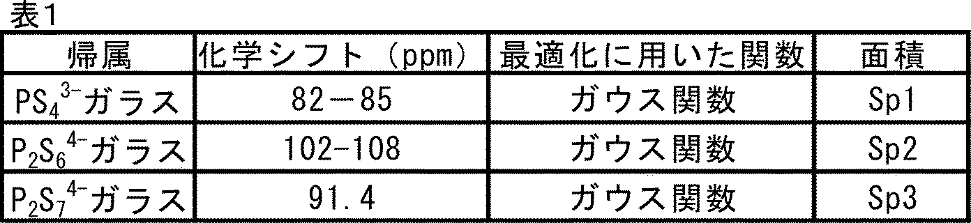
PS4
3-リン比率(%):100×Sp1/(Sp1+Sp2+Sp3)
P2S6 4-リン比率(%):100×Sp2/(Sp1+Sp2+Sp3)
P2S7 4-リン比率(%):100×Sp3/(Sp1+Sp2+Sp3) PS 4 3- Phosphorus ratio (%): 100 x Sp1 / (Sp1 + Sp2 + Sp3)
P 2 S 6 4- phosphorus ratio (%): 100 x Sp2 / (Sp1 + Sp2 + Sp3)
P 2 S 7 4- phosphorus ratio (%): 100 x Sp3 / (Sp1 + Sp2 + Sp3)
P2S6 4-リン比率(%):100×Sp2/(Sp1+Sp2+Sp3)
P2S7 4-リン比率(%):100×Sp3/(Sp1+Sp2+Sp3) PS 4 3- Phosphorus ratio (%): 100 x Sp1 / (Sp1 + Sp2 + Sp3)
P 2 S 6 4- phosphorus ratio (%): 100 x Sp2 / (Sp1 + Sp2 + Sp3)
P 2 S 7 4- phosphorus ratio (%): 100 x Sp3 / (Sp1 + Sp2 + Sp3)
(1-5-2)結晶性固体電解質(A)の場合
各リン含有構造の化学シフトとして表2を用いた以外は(1-5-1)に準ずる方法でリン比率を求めた。 (1-5-2) In the case of the crystalline solid electrolyte (A), the phosphorus ratio was determined by the method according to (1-5-1) except that Table 2 was used as the chemical shift of each phosphorus-containing structure.
各リン含有構造の化学シフトとして表2を用いた以外は(1-5-1)に準ずる方法でリン比率を求めた。 (1-5-2) In the case of the crystalline solid electrolyte (A), the phosphorus ratio was determined by the method according to (1-5-1) except that Table 2 was used as the chemical shift of each phosphorus-containing structure.
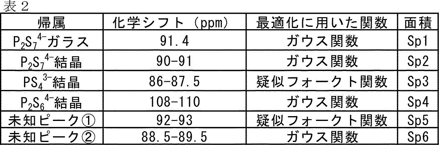
なお、P2S7
4-リン比率はP2S7
4-ガラスリンの比率とP2S7
4-結晶リンの比率の和として定義した。
また、PS4 3-結晶のピークを1個の疑似フォークト関数で十分に最適化できない場合、2個の疑似フォークト関数を用いて分離した。 The P 2 S 7 4- phosphorus ratio was defined as the sum of the ratio of P 2 S 7 4- glass phosphorus and the ratio of P 2 S 7 4- crystalline phosphorus.
Moreover, when the peak of PS 43- crystal could not be sufficiently optimized by one pseudo Voigt function, it was separated by using two pseudo Voigt functions.
(1-5-3)本発明の硫化物固体電解質ガラスセラミクスの場合
各リン含有構造の化学シフトとして表3を用いた以外は(1-5-1)に準ずる方法でリン比率を求めた。 (1-5-3) In the case of the sulfide solid electrolyte glass ceramics of the present invention, the phosphorus ratio was determined by the method according to (1-5-1) except that Table 3 was used as the chemical shift of each phosphorus-containing structure.
各リン含有構造の化学シフトとして表3を用いた以外は(1-5-1)に準ずる方法でリン比率を求めた。 (1-5-3) In the case of the sulfide solid electrolyte glass ceramics of the present invention, the phosphorus ratio was determined by the method according to (1-5-1) except that Table 3 was used as the chemical shift of each phosphorus-containing structure.

(1-6)示差熱分析(DTA)測定(半値幅決定)
装置:METTLER TOLED社製TGA/DSC3+
測定条件:N2ガス60mL/min 流通下、25℃で10分間保持後、600℃まで10℃/minで昇温 (1-6) Differential thermal analysis (DTA) measurement (half-value width determination)
Equipment: TGA / DSC3 + manufactured by METTLER TOLED
Measurement conditions: N 2 gas 60 mL / min flow, hold at 25 ° C for 10 minutes, then heat up to 600 ° C at 10 ° C / min
非晶質材料のDTA測定を実施。昇温過程において130℃以上で最初に観測される発熱ピークに着目し、その発熱ピーク曲線に直線によるベースラインを設定し、各点の強度とベースラインの差分をとり、DTA曲線とした((1-2)のXRD曲線決定と同様の方法)。この曲線のカーブフィットをローレンツ関数やガウス関数で試みたが良好な近似曲線が得られなかったため、DTA曲線のピーク値の半値を与える温度TH、TL(但し、TH>TL)を求め、その差分を半値幅と定義した。
Conducted DTA measurement of amorphous material. Focusing on the exothermic peak first observed at 130 ° C or higher in the temperature rise process, a linear baseline was set for the exothermic peak curve, and the difference between the intensity and baseline of each point was taken to obtain the DTA curve ((((). 1-2) The same method as the XRD curve determination). We tried the curve fit of this curve with the Lorentz function and Gaussian function , but we could not obtain a good approximation curve. It was calculated and the difference was defined as the half width.
(1-7)示差熱分析(DTA)測定(ピーク温度、熱量)
硫化物固体電解質ガラスセラミクスのDTA測定を実施(条件:(1-6)参照)。350℃以下で観測される発熱ピークに着目し、(1-6)で示したのと同様のやり方で、発熱ピーク曲線に直線によるベースラインを設定し、各点の強度とベースラインの差分をとり、DTA曲線とした。この曲線からピーク温度(℃)、発熱量(W/g)を読み取った。 (1-7) Differential thermal analysis (DTA) measurement (peak temperature, calorific value)
DTA measurement of sulfide solid electrolyte glass ceramics was carried out (conditions: see (1-6)). Focusing on the exothermic peak observed at 350 ° C or lower, set a linear baseline on the exothermic peak curve in the same manner as shown in (1-6), and calculate the difference between the intensity and baseline at each point. It was taken as a DTA curve. The peak temperature (° C.) and calorific value (W / g) were read from this curve.
(1-8)耐水性評価(H2S発生量)
暴露試験装置(図4)は、窒素を加湿するフラスコ10と、加湿した窒素と加湿しない窒素とを混合するスタティックミキサー20と、混合した窒素の水分を測定する露点計30(VAISALA社製M170/DMT152)と、測定試料を設置する二重反応管40と、二重反応管40から排出される窒素の水分を測定する露点計50と、排出された窒素中に含まれる硫化水素濃度を測定する硫化水素計測器60(AMI社製 Model3000RS)とを、主な構成要素とし、これらを管(図示せず)にて接続した構成としてある。フラスコ10の温度は冷却槽11により10℃に設定されている。
なお、各構成要素を接続する菅には直径6mmのテフロン(登録商標)チューブを使用した。本図4では管の表記を省略し、代わりに窒素の流れを矢印で示してある。 (1-8) Water resistance evaluation ( H2S generation amount)
The exposure test device (FIG. 4) includes aflask 10 for humidifying nitrogen, a static mixer 20 for mixing humidified nitrogen and non-humidified nitrogen, and a dew point meter 30 for measuring the water content of the mixed nitrogen (M170 / manufactured by VAISALA). DMT152), a double reaction tube 40 in which a measurement sample is installed, a dew point meter 50 for measuring the water content of nitrogen discharged from the double reaction tube 40, and a concentration of hydrogen sulfide contained in the discharged nitrogen are measured. A hydrogen sulfide measuring instrument 60 (Model3000RS manufactured by AMI) is used as a main component, and these are connected by a pipe (not shown). The temperature of the flask 10 is set to 10 ° C. by the cooling tank 11.
A Teflon (registered trademark) tube having a diameter of 6 mm was used for the tube connecting each component. In FIG. 4, the notation of the tube is omitted, and instead, the flow of nitrogen is indicated by an arrow.
暴露試験装置(図4)は、窒素を加湿するフラスコ10と、加湿した窒素と加湿しない窒素とを混合するスタティックミキサー20と、混合した窒素の水分を測定する露点計30(VAISALA社製M170/DMT152)と、測定試料を設置する二重反応管40と、二重反応管40から排出される窒素の水分を測定する露点計50と、排出された窒素中に含まれる硫化水素濃度を測定する硫化水素計測器60(AMI社製 Model3000RS)とを、主な構成要素とし、これらを管(図示せず)にて接続した構成としてある。フラスコ10の温度は冷却槽11により10℃に設定されている。
なお、各構成要素を接続する菅には直径6mmのテフロン(登録商標)チューブを使用した。本図4では管の表記を省略し、代わりに窒素の流れを矢印で示してある。 (1-8) Water resistance evaluation ( H2S generation amount)
The exposure test device (FIG. 4) includes a
A Teflon (registered trademark) tube having a diameter of 6 mm was used for the tube connecting each component. In FIG. 4, the notation of the tube is omitted, and instead, the flow of nitrogen is indicated by an arrow.
評価の手順は以下のとおりとした。
露点を-80℃とした窒素グローボックス内で、粉末試料41を約0.15g秤量し、石英ウール42で挟むように反応管40内部に設置し密封した。 The evaluation procedure was as follows.
About 0.15 g of thepowder sample 41 was weighed in a nitrogen glove box having a dew point of −80 ° C., placed inside the reaction tube 40 so as to be sandwiched between quartz wool 42, and sealed.
露点を-80℃とした窒素グローボックス内で、粉末試料41を約0.15g秤量し、石英ウール42で挟むように反応管40内部に設置し密封した。 The evaluation procedure was as follows.
About 0.15 g of the
窒素源(図示せず)から0.02MPaで窒素を装置1内に供給した。供給された窒素は、二又分岐管BPを通過して、一部はフラスコ10に供給され加湿される。その他は加湿しない窒素としてスタティックミキサー20に直接供給される。なお、窒素のフラスコ10への供給量はニードルバルブVで調整される。
加湿しない窒素及び加湿した窒素の流量を、ニードルバルブ付きフローメーターFMで調整することにより露点を制御する。具体的に、加湿しない窒素の流量を800mL/min、加湿した窒素の流量を10~30mL/minで、スタティックミキサー20に供給し、混合して、露点計30にて混合ガス(加湿しない窒素及び加湿した窒素の混合物)の露点を確認した。 Nitrogen was supplied into theapparatus 1 from a nitrogen source (not shown) at 0.02 MPa. The supplied nitrogen passes through the bifurcated branch pipe BP, and a part of the supplied nitrogen is supplied to the flask 10 and humidified. Others are directly supplied to the static mixer 20 as nitrogen that is not humidified. The amount of nitrogen supplied to the flask 10 is adjusted by the needle valve V.
The dew point is controlled by adjusting the flow rates of unhumidified nitrogen and humidified nitrogen with a flow meter FM equipped with a needle valve. Specifically, the flow rate of unhumidified nitrogen is 800 mL / min, and the flow rate of humidified nitrogen is 10 to 30 mL / min. The dew point of the humidified nitrogen mixture) was confirmed.
加湿しない窒素及び加湿した窒素の流量を、ニードルバルブ付きフローメーターFMで調整することにより露点を制御する。具体的に、加湿しない窒素の流量を800mL/min、加湿した窒素の流量を10~30mL/minで、スタティックミキサー20に供給し、混合して、露点計30にて混合ガス(加湿しない窒素及び加湿した窒素の混合物)の露点を確認した。 Nitrogen was supplied into the
The dew point is controlled by adjusting the flow rates of unhumidified nitrogen and humidified nitrogen with a flow meter FM equipped with a needle valve. Specifically, the flow rate of unhumidified nitrogen is 800 mL / min, and the flow rate of humidified nitrogen is 10 to 30 mL / min. The dew point of the humidified nitrogen mixture) was confirmed.
露点を-20℃に調整した後、三方コック43を回転して、混合ガスを反応管40内部に4時間流通させた。試料41を通過した混合ガスに含まれる硫化水素量を、硫化水素計測器60で測定した。この間に発生した硫化水素量をサンプル1g当りに換算して求めた(単位:cc/g)。なお、測定後のガスは硫化水素を除去するため、アルカリトラップ70を通過させた。
所定時間試料を暴露させた後、加湿した窒素の供給を止め、加湿しない窒素で反応管40を密閉した。 After adjusting the dew point to −20 ° C., the three-way cock 43 was rotated to allow the mixed gas to flow inside the reaction tube 40 for 4 hours. The amount of hydrogen sulfide contained in the mixed gas that passed through the sample 41 was measured by the hydrogen sulfide measuring instrument 60. The amount of hydrogen sulfide generated during this period was converted into 1 g of a sample and obtained (unit: cc / g). The gas after the measurement was passed through an alkaline trap 70 in order to remove hydrogen sulfide.
After exposing the sample for a predetermined time, the supply of humidified nitrogen was stopped, and thereaction tube 40 was sealed with unhumidified nitrogen.
所定時間試料を暴露させた後、加湿した窒素の供給を止め、加湿しない窒素で反応管40を密閉した。 After adjusting the dew point to −20 ° C., the three-
After exposing the sample for a predetermined time, the supply of humidified nitrogen was stopped, and the
(1-9)CV測定(不可逆容量)
不可逆容量を評価するため、下記のCV測定用セルを用いた。
実施例及び比較例で得られた各硫化物固体電解質ガラスセラミクス0.3846gとデンカブラック粒状(デンカ株式会社製)0.1154g(質量比で、硫化物固体電解質ガラスセラミクス:デンカブラック粒状=50:15)を乳鉢を用いて10分間混合し、測定用粉体(1)を得た。
直径10mmの電池セルに、更にセパレータ―層用の電解質60mgを加え、SUS製金型で2.55MPa/cm2で3回プレスした後、測定用粉体(1)を3.5mg加え、5.10MPa/cm2で3回プレスした。更に測定用粉体(1)の逆側から、2.55MPa/cm2、5.10MPa/cm2、7.64MPa/cm2で3回プレスした。
なお、CV測定セパレーター用電解質は以下の条件で合成した。
1L撹拌良翼付き反応容器に、窒素雰囲気下でL2Sを20.5g、P2S5を33.1g、LiIを10.0g、LiBrを6.5g添加した。撹拌翼を回転させた後、トルエン630gを導入し、このスラリーを10分間撹拌した。循環運転可能なビーズミル(商品名:スターミルLMZ015、アシザワファインテック株式会社製、0.5mm径ジルコニア製ビーズを456g充填)に反応容器を接続し、ポンプ流量:650mL/min、ビーズミル周速:12m/s、ミルジャケット温度45℃で45時間粉砕処理を行った。得られたスラリーを真空下で室温乾燥(25℃)した後、80℃の加熱を行い非晶性の固体電解質の白色粉末を得た。さらに、得られた白色粉末を真空下で195℃の加熱を2時間行うことにより、結晶性の固体電解質の白色粉末を得た。結晶性固体電解質のXRDスペクトルでは2θ=20.2°、23.6°に結晶化ピークが検出され、チオリシコンリージョンII型結晶構造を有していることを確認した。得られた結晶性固体電解質の平均粒径(D50)は4.5μm、伝導度は5.0mS/cmであった。 (1-9) CV measurement (irreversible capacity)
In order to evaluate the irreversible capacity, the following CV measurement cell was used.
0.3846 g of each sulfide solid electrolyte glass ceramics obtained in Examples and Comparative Examples and 0.1154 g of Denka Black Granules (manufactured by Denka Co., Ltd.) (by mass ratio, sulfide solid electrolyte glass ceramics: Denka Black Granules = 50: 15) was mixed for 10 minutes using a dairy pot to obtain a measurement powder (1).
Further, 60 mg of the electrolyte for the separator layer is added to the battery cell having a diameter of 10 mm, and after pressing 3 times at 2.55 MPa / cm 2 with a SUS die, 3.5 mg of the measurement powder (1) is added and 5 . Pressed 3 times at 10 MPa / cm 2 . Further, from the opposite side of the measuring powder (1), the mixture was pressed three times at 2.55 MPa / cm 2 , 5.10 MPa / cm 2, and 7.64 MPa / cm 2 .
The electrolyte for the CV measurement separator was synthesized under the following conditions.
20.5 g of L2S , 33.1 g of P2S5 , 10.0 g of LiI, and 6.5 g of LiBr were added to a 1 L stirring reaction vessel with good wings under a nitrogen atmosphere. After rotating the stirring blade, 630 g of toluene was introduced and the slurry was stirred for 10 minutes. A reaction vessel is connected to a bead mill capable of circulating operation (trade name: Star Mill LMZ015, manufactured by Ashizawa Finetech Co., Ltd., filled with 456 g of beads made of 0.5 mm diameter zirconia), pump flow rate: 650 mL / min, bead mill peripheral speed: 12 m / s, Grinding treatment was carried out at a mill jacket temperature of 45 ° C. for 45 hours. The obtained slurry was dried at room temperature (25 ° C.) under vacuum and then heated at 80 ° C. to obtain a white powder of an amorphous solid electrolyte. Further, the obtained white powder was heated at 195 ° C. under vacuum for 2 hours to obtain a white powder of a crystalline solid electrolyte. Crystallization peaks were detected at 2θ = 20.2 ° and 23.6 ° in the XRD spectrum of the crystalline solid electrolyte, confirming that the crystal had a thiolyricon region type II crystal structure. The average particle size (D 50 ) of the obtained crystalline solid electrolyte was 4.5 μm, and the conductivity was 5.0 mS / cm.
セパレータ―層用の電解質の測定用粉体(1)とは逆側にInLi箔(層構造をなし、「/」は各層間を意味する。In 10mmφ×0.1mm/Li 9mmφ×0.1mm/In 9.5mmφ×0.1mm/Li 9mmφ×0.1mm /In 9.5mmφ×0.1mm)を設け、更にTi箔によりSUS製金型との付着を防止した。この状態で、更に1.27MPa/cm2で1回プレスした。セルは測定用粉体(1)とInLi箔間で短絡しないよう、絶縁体を挟んだ4本のねじにより固定され、ねじは8Nmをトルクで固定することで測定用セルを得た。
Separator-InLi foil (having a layer structure, "/" means each layer. In 10 mmφ x 0.1 mm / Li 9 mmφ x 0.1 mm on the opposite side to the powder (1) for measuring the electrolyte for the layer. / In 9.5 mmφ × 0.1 mm / Li 9 mmφ × 0.1 mm / In 9.5 mmφ × 0.1 mm) was provided, and the Ti foil was used to prevent adhesion to the SUS mold. In this state, it was further pressed once at 1.27 MPa / cm 2 . The cell was fixed by four screws sandwiching an insulator so as not to cause a short circuit between the measuring powder (1) and the InLi foil, and the screws were fixed at 8 Nm with torque to obtain a measuring cell.
得られた測定用セルは、測定器(VSP-3 Biologic社製)と接続し、下記の条件のもと、CV曲線を得た。
測定温度:25℃
掃引速度:0.1mV/s
電位測定範囲:開回路電圧(約+1.9V)→+5.0V→+1.8V
得られたCV曲線を、流れる電流(CurrentI(mA))と時間経過にプロットしなおした(図18)。ここから使用した硫化物固体電解質ガラスセラミクスの質量当たりの容量を算出し、これを積算して飽和した容量を不可逆容量(mAh/g)とした(図19)。
(1-10) 平均粒径(D50)
体積基準平均粒径は、レーザー回折/散乱式粒子径分布測定装置(「Partica LA-950V2モデルLA-950W2」、株式会社堀場製作所製)を用いて測定した。脱水処理された、トルエン(和光純薬製、特級)とターシャリーブチルアルコール(和光純薬製、特級)を93.8:6.2の重量比で混合したものを分散媒として用いた。装置のフローセル内に分散倍を50ml注入し、循環させた後、測定対象を添加して超音波処理をしたのち、粒子径分布を測定した。なお、測定対象の添加量は装置で規定されている測定画面で、粒子濃度に対応する赤色光透過率(R)が90~90%、青色光透過率(B)が70~90%に収まるように調整した。また、演算条件には、測定対象の屈折率の値として2.16を、分散媒の屈折率の値として1.49をそれぞれ用いた。分布形態の設定において、反復回数を15回に固定して粒径演算を行った。 The obtained measuring cell was connected to a measuring instrument (manufactured by VSS-3 Biological), and a CV curve was obtained under the following conditions.
Measurement temperature: 25 ° C
Sweep speed: 0.1 mV / s
Potential measurement range: Open circuit voltage (about + 1.9V) → + 5.0V → + 1.8V
The obtained CV curve was re-plotted with the flowing current (CurrentI (mA)) and the passage of time (FIG. 18). From this, the capacity per mass of the sulfide solid electrolyte glass ceramics used was calculated, and this was integrated to determine the saturated capacity as the irreversible capacity (mAh / g) (FIG. 19).
(1-10) Average particle size (D 50 )
The volume-based average particle size was measured using a laser diffraction / scattering type particle size distribution measuring device (“Partica LA-950V2 model LA-950W2”, manufactured by HORIBA, Ltd.). A dehydrated mixture of toluene (manufactured by Wako Pure Chemical Industries, Ltd., special grade) and tert-butyl alcohol (manufactured by Wako Pure Chemical Industries, Ltd., special grade) at a weight ratio of 93.8: 6.2 was used as a dispersion medium. After injecting 50 ml of the dispersion double into the flow cell of the apparatus and circulating it, the measurement target was added and ultrasonic treatment was performed, and then the particle size distribution was measured. The amount of addition to be measured is 90 to 90% for the red light transmittance (R) and 70 to 90% for the blue light transmittance (B) corresponding to the particle concentration on the measurement screen specified by the device. Adjusted to. Further, as the calculation conditions, 2.16 was used as the value of the refractive index of the measurement target, and 1.49 was used as the value of the refractive index of the dispersion medium. In setting the distribution form, the particle size was calculated by fixing the number of repetitions to 15 times.
(2) 硫化リチウム(Li2S)及び五硫化二リン(P2S5)の作製例
(2-1) 硫化リチウム(Li2S)の作製例 (2) Example of production of lithium sulfide (Li 2 S) and diphosphorus pentasulfide (P 2 S 5 ) (2-1) Example of production of lithium sulfide (Li 2 S)
(2-1) 硫化リチウム(Li2S)の作製例 (2) Example of production of lithium sulfide (Li 2 S) and diphosphorus pentasulfide (P 2 S 5 ) (2-1) Example of production of lithium sulfide (Li 2 S)
(2-1-1)Li2Sの作製
非水溶性媒体としてトルエン(住友商事株式会社製)を脱水処理(カールフィッシャー水分計にて測定し、水分量が100ppm以下であることを確認した。)した303.8kgを、窒素気流下で、500L(リットル)ステンレス製反応釜に加え、続いて無水水酸化リチウム33.8kg(本荘ケミカル株式会社製)を投入し、95℃で2時間、ツインスター撹拌翼を用いて、131rpmで撹拌しスラリーとした。 ( 2-1-1) Preparation of Li 2S Toluene (manufactured by Sumitomo Corporation) was dehydrated (measured with a Karl Fischer titer) as a water-insoluble medium, and it was confirmed that the water content was 100 ppm or less. ) 303.8 kg was added to a 500 L (liter) stainless steel reaction kettle under a nitrogen stream, and then 33.8 kg of anhydrous lithium hydroxide (manufactured by Honjo Chemical Co., Ltd.) was added, and the twin was added at 95 ° C. for 2 hours. Using a star stirring blade, the mixture was stirred at 131 rpm to obtain a slurry.
非水溶性媒体としてトルエン(住友商事株式会社製)を脱水処理(カールフィッシャー水分計にて測定し、水分量が100ppm以下であることを確認した。)した303.8kgを、窒素気流下で、500L(リットル)ステンレス製反応釜に加え、続いて無水水酸化リチウム33.8kg(本荘ケミカル株式会社製)を投入し、95℃で2時間、ツインスター撹拌翼を用いて、131rpmで撹拌しスラリーとした。 ( 2-1-1) Preparation of Li 2S Toluene (manufactured by Sumitomo Corporation) was dehydrated (measured with a Karl Fischer titer) as a water-insoluble medium, and it was confirmed that the water content was 100 ppm or less. ) 303.8 kg was added to a 500 L (liter) stainless steel reaction kettle under a nitrogen stream, and then 33.8 kg of anhydrous lithium hydroxide (manufactured by Honjo Chemical Co., Ltd.) was added, and the twin was added at 95 ° C. for 2 hours. Using a star stirring blade, the mixture was stirred at 131 rpm to obtain a slurry.
更に撹拌を継続しながら、スラリー中に硫化水素(住友精化株式会社製)を100L/分の供給速度で吹き込みながら、104℃まで昇温した。反応釜からは、水とトルエンの共沸ガスが連続的に排出された。この共沸ガスを、系外のコンデンサで凝縮させることにより脱水した。この間、留出するトルエンと同量のトルエンを連続的に供給し、反応液レベルを一定に保持した。
凝縮液中の水分量は徐々に減少し、硫化水素導入後24時間で水の留出は認められなくなった。なお、反応の間は、トルエン中に固体が分散して撹拌された状態であり、トルエンから分層した水分は無かった。 While continuing stirring, hydrogen sulfide (manufactured by Sumitomo Seika Chemical Co., Ltd.) was blown into the slurry at a supply rate of 100 L / min, and the temperature was raised to 104 ° C. Azeotropic gas of water and toluene was continuously discharged from the reaction kettle. This azeotropic gas was dehydrated by condensing it with a capacitor outside the system. During this period, the same amount of toluene as the distilled toluene was continuously supplied to keep the reaction solution level constant.
The amount of water in the condensate gradually decreased, and no distillate of water was observed 24 hours after the introduction of hydrogen sulfide. During the reaction, the solid was dispersed in toluene and stirred, and there was no water separated from the toluene.
この後、硫化水素を窒素に切り替え100L/分で1時間流通した。
得られた固形分をろ過及び乾燥して、白色粉末であるLi2Sを得た。Li2SのD50は412μmであった。 After that, hydrogen sulfide was switched to nitrogen and circulated at 100 L / min for 1 hour.
The obtained solid content was filtered and dried to obtain Li 2S as a white powder. The D50 of Li 2S was 412 μm.
得られた固形分をろ過及び乾燥して、白色粉末であるLi2Sを得た。Li2SのD50は412μmであった。 After that, hydrogen sulfide was switched to nitrogen and circulated at 100 L / min for 1 hour.
The obtained solid content was filtered and dried to obtain Li 2S as a white powder. The D50 of Li 2S was 412 μm.
(2-1-2) Li2Sの粉砕
(2-1-1)で得たLi2Sを、窒素雰囲気下にて、定量供給機を有するピンミル(ホソカワミクロン株式会社製 100UPZ)にて粉砕した。投入速度は80g/min、円板の回転速度は18000rpmとした。
粉砕処理後のLi2SのD50は7.7μmであった。 (2-1-2) Crushing of Li 2 S The Li 2 S obtained in (2-1-1) was crushed under a nitrogen atmosphere with a pin mill (100UPZ manufactured by Hosokawa Micron Co., Ltd.) equipped with a quantitative feeder. .. The charging speed was 80 g / min, and the rotation speed of the disk was 18000 rpm.
The D50 of Li 2S after the pulverization treatment was 7.7 μm.
(2-2) 五硫化二リン(P2S5)の作製例
(2-2-1) P2S5の粉砕
(2-1-2)において、(2-1-1)で得たLi2Sに換えてP2S5(サーモフォス製、D50=125μm)を用いる以外は同様にして粉砕した。
粉砕処理後のP2S5のD50は8.7μmであった。 (2-2) Example of Preparation of Diphosphorus pentasulfide (P 2 S 5 ) (2-2-1) Obtained in (2-1-1) in pulverization of P 2 S 5 (2-1-2). It was pulverized in the same manner except that P 2 S 5 (manufactured by Thermophos, D 50 = 125 μm) was used instead of Li 2 S.
The D50 of P2 S 5 after the pulverization treatment was 8.7 μm .
(実施例1)
工程(A)
(2-1-2)で製造したLi2Sを0.488g(45.947g/mol、0.01062mol)、(2-2-2)で製造したP2S5を1.012g(222.272g/mol、0.00455mol)及び直径10mmのジルコニア製ボール10個(約32g)とを遊星型ボールミル(フリッチュ社製:型番P-7)ジルコニア製ポット(45mL)に入れ、完全密閉し、ポット内をアルゴン雰囲気とした。加熱冷却することなく、遊星型ボールミルで回転数を370rpmとし、40時間処理(メカニカルミリング)し、粉末(固体電解質(A1))を得た。
得られた粉末について、X線回折(XRD)測定(図5)により非晶質固体電解質であることが確認できた。また固体31P-NMR測定行い、P2S7 4-リン比率(表4)を評価した。 (Example 1)
Process (A)
0.488 g (45.947 g / mol, 0.01062 mol) of Li 2 S produced in (2-1-2) and 1.012 g (222.) of P 2 S 5 produced in (2--2-2). 272 g / mol, 0.00455 mol) and 10 zirconia balls (about 32 g) having a diameter of 10 mm were placed in a planetary ball mill (Fritsch: model number P-7) zirconia pot (45 mL), completely sealed, and potted. The inside was made into an argon atmosphere. A powder (solid electrolyte (A1)) was obtained by processing (mechanical milling) for 40 hours at a rotation speed of 370 rpm with a planetary ball mill without heating and cooling.
It was confirmed that the obtained powder was an amorphous solid electrolyte by X-ray diffraction (XRD) measurement (FIG. 5). In addition, solid 31 P - NMR measurement was performed to evaluate the P2 S 7 4- phosphorus ratio (Table 4).
工程(B)
工程(A)で得た固体電解質(A1)を1.035g量り取り、それにLi2Sを0.096g(0.00209mol)、更にハロゲン化リチウムとしてLiIを0.369g(133.845g/mol、0.00276mol)を添加する以外は上記工程(A)と同様にして非晶質固体電解質(B1)を得た。非晶質固体電解質(B1)のX線回折(XRD)測定、及び示差熱(DTA)分析の結果をそれぞれ図6、図7に示す。また、固体31P-NMR測定でP2S6 4-リン比率を、示差熱(DTA)分析により昇温過程で130℃以上の温度で最初に出現する発熱ピークの温度および半値幅を評価した(表4)。 Process (B)
Weigh 1.035 g of the solid electrolyte (A1) obtained in the step (A), 0.096 g ( 0.00209 mol) of Li 2S, and 0.369 g (133.845 g / mol) of Li I as lithium halide. An amorphous solid electrolyte (B1) was obtained in the same manner as in the above step (A) except that 0.00276 mol) was added. The results of X-ray diffraction (XRD) measurement and differential thermal (DTA) analysis of the amorphous solid electrolyte (B1) are shown in FIGS. 6 and 7, respectively. In addition, the P2 S 6 4- phosphorus ratio was evaluated by solid 31 P - NMR measurement, and the temperature and half-value width of the exothermic peak that first appeared at a temperature of 130 ° C. or higher in the heating process was evaluated by differential thermal (DTA) analysis. (Table 4).
加熱(結晶化)工程
工程(B)で得られた非晶質固体電解質(B1)の全量をアルゴン雰囲気としたグローボックス内で、ホットプレートにて180℃で2時間加熱した。
その後、徐冷し、アルゴン雰囲気下のグローブボックス内で、乳鉢で粉砕して粉末(硫化物固体電解質ガラスセラミクス(1))を得た。硫化物固体電解質ガラスセラミクス(1)の示差熱(DTA)分析の結果を図8に示す。 Heating (crystallization) step The whole amount of the amorphous solid electrolyte (B1) obtained in the step (B) was heated at 180 ° C. for 2 hours on a hot plate in a glove box having an argon atmosphere.
Then, it was slowly cooled and pulverized in a mortar in a glove box under an argon atmosphere to obtain a powder (sulfide solid electrolyte glass ceramics (1)). The result of the differential thermal (DTA) analysis of the sulfide solid electrolyte glass ceramics (1) is shown in FIG.
得られた粉末についてX線回折(XRD)測定(図9)により、2θ=20.2°、23.6°にチオリシコンリージョンII類似の結晶構造に由来するピークが観測された。結晶子径は、表4に示す。
また固体31P-NMR測定によるP2S6 4-リン比率、示差熱(DTA)分析による350℃以下に現れる発熱ピーク温度と強度(熱量)、及びICP測定による元素比から換算したILi2S/IP2S5も併せて表5に示す。さらに、前述の方法に従ってイオン伝導度(表中では伝導度と記載)、耐水性(表中ではH2S発生量として記載)及び不可逆容量を評価した(表5)。 By X-ray diffraction (XRD) measurement (FIG. 9) of the obtained powder, peaks derived from a crystal structure similar to Thioricicon Region II were observed at 2θ = 20.2 ° and 23.6 °. The crystallite diameter is shown in Table 4.
In addition, I Li2S / converted from the P 2 S 6 4- phosphorus ratio measured by solid 31 P-NMR, the exothermic peak temperature and intensity (calorific value) appearing below 350 ° C by differential heat (DTA) analysis, and the element ratio measured by ICP. I P2S5 is also shown in Table 5. Further, the ionic conductivity (described as conductivity in the table), water resistance (described as H2S generation amount in the table) and irreversible capacity were evaluated according to the above-mentioned method (Table 5).
(比較例1)
(2-1-2)で製造したLi2Sを0.433g(0.00942mol)、(2-2-2)で製造したP2S5を0.698g(0.00314mol)、ハロゲン化リチウムとしてLiIを0.369g(0.00276mol)、及び直径2mmのジルコニア製ボール53g、溶媒エチルベンゼン(5mL)とを遊星型ボールミル(フリッチュ社製:型番P-7)ジルコニア製ポット(45mL)に入れ、完全密閉し、ポット内をアルゴン雰囲気とした。加熱冷却することなく、遊星型ボールミルで回転数を500rpmとし、40時間処理(メカニカルミリング)し、得られたスラリーを真空下で室温乾燥した後、80℃の加熱を行い粉末(非晶質固体電解質(C1))を得た。
得られた粉末について、X線回折(XRD)測定により非晶質固体電解質であることが確認できた。 (Comparative Example 1)
Li 2 S produced in (2-1-2) was 0.433 g (0.00942 mol), P 2 S 5 produced in (2--2-2) was 0.698 g (0.00314 mol), and lithium halide. As a result, 0.369 g (0.00276 mol) of LiI, 53 g of zirconia balls having a diameter of 2 mm, and ethylbenzene (5 mL) as a solvent were placed in a planetary ball mill (Fritsch: model number P-7) zirconia pot (45 mL). It was completely sealed and the inside of the pot had an argon atmosphere. The slurry was treated with a planetary ball mill at 500 rpm for 40 hours (mechanical milling) without heating and cooling, and the obtained slurry was dried at room temperature under vacuum and then heated at 80 ° C. to form a powder (amorphous solid). Electrolyte (C1)) was obtained.
It was confirmed that the obtained powder was an amorphous solid electrolyte by X-ray diffraction (XRD) measurement.
結晶化工程
得られた非晶質硫化物固体電解質(C1)の全量をアルゴン雰囲気としたグローブボックス内で、ホットプレートにて195℃で2時間加熱した。
その後、徐冷し、アルゴン雰囲気下のグローブボックス内で、乳鉢で粉砕して粉末(硫化物固体電解質ガラスセラミクス(C1))を得た。
得られた粉末について、X線回折(XRD)測定(図15)によりチオリシコンリージョンII類似の結晶構造に由来するピークが観測され、硫化物固体電解質ガラスセラミクス(C1)であることが確認できた。
硫化物固体電解質ガラスセラミクス(C1)の示差熱(DTA)分析の結果を図16に示す。 Crystallization step The whole amount of the obtained amorphous sulfide solid electrolyte (C1) was heated at 195 ° C. for 2 hours on a hot plate in a glove box having an argon atmosphere.
Then, it was slowly cooled and pulverized in a mortar in a glove box under an argon atmosphere to obtain a powder (sulfide solid electrolyte glass ceramics (C1)).
For the obtained powder, a peak derived from a crystal structure similar to that of Thioricicon Region II was observed by X-ray diffraction (XRD) measurement (FIG. 15), and it was confirmed that the powder was sulfide solid electrolyte glass ceramics (C1). ..
The result of the differential thermal (DTA) analysis of the sulfide solid electrolyte glass ceramics (C1) is shown in FIG.
(比較例2)
前記(比較例1)において、溶媒を使用せずに、直径10mmのジルコニア製ボール10個(約32g)を使用し、370rpmでメカニカルミリングした以外は同様にして、比較例2の硫化物固体電解質ガラスセラミクスを得た。 (Comparative Example 2)
In the above (Comparative Example 1), the sulfide solid electrolyte of Comparative Example 2 was similarly used except that 10 zirconia balls (about 32 g) having a diameter of 10 mm were used and mechanically milled at 370 rpm without using a solvent. Obtained glass ceramics.
(実施例2)
加熱(結晶化)工程(1回目)
実施例1において、工程(A)で得られた固体電解質(A1)の全量をアルゴン雰囲気としたグローブボックス内で、電気炉にて250℃で3時間加熱した。
その後、徐冷し、アルゴン雰囲気下のグローブボックス内で、乳鉢で粉砕して粉末(結晶性固体電解質(A2))を得た。X線回折(XRD)測定の結果を図10に示す。 (Example 2)
Heating (crystallization) process (1st time)
In Example 1, the solid electrolyte (A1) obtained in the step (A) was heated at 250 ° C. for 3 hours in a glove box having an argon atmosphere.
Then, it was slowly cooled and pulverized in a mortar in a glove box under an argon atmosphere to obtain a powder (crystalline solid electrolyte (A2)). The result of the X-ray diffraction (XRD) measurement is shown in FIG.
工程(B)
加熱(結晶化)工程(1回目)で得られた粉末を1.035g量り取り、それにLi2Sを0.096g(0.00209mol)を添加し、更にハロゲン化リチウムとしてLiIを0.369g(0.00276mol)添加する以外は実施例1の工程(B)と同様にして非晶質固体電解質(B2)を得た。 Process (B)
Weigh 1.035 g of the powder obtained in the heating (crystallization) step (first time), add 0.096 g ( 0.00209 mol) of Li 2S to it, and add 0.369 g of Li I as lithium halide. An amorphous solid electrolyte (B2) was obtained in the same manner as in the step (B) of Example 1 except that 0.00276 mol) was added.
加熱(結晶化)工程(2回目)
工程(B)で得られた非晶質固体電解質(B2)の全量をアルゴン雰囲気としたグローブボックス内で、ホットプレートにて185℃で2時間加熱した。
その後、徐冷し、アルゴン雰囲気下のグローブボックス内で、乳鉢で粉砕して粉末(硫化物固体電解質ガラスセラミクス(2))を得た。 Heating (crystallization) process (second time)
The whole amount of the amorphous solid electrolyte (B2) obtained in the step (B) was heated at 185 ° C. for 2 hours on a hot plate in a glove box having an argon atmosphere.
Then, it was slowly cooled and pulverized in a mortar in a glove box under an argon atmosphere to obtain a powder (sulfide solid electrolyte glass ceramics (2)).
得られた粉末についてX線回折(XRD)測定を行った。X線回折の結果、2θ=20.2°、23.6°にチオリシコンリージョンII類似の結晶構造に由来するピークが観測され、結晶性固体電解質(ガラスセラミック)であることが確認できた。
硫化物固体電解質ガラスセラミクス(2)の示差熱(DTA)分析の結果を図11に示す。 X-ray diffraction (XRD) measurement was performed on the obtained powder. As a result of X-ray diffraction, peaks derived from a crystal structure similar to Thioricicon Region II were observed at 2θ = 20.2 ° and 23.6 °, confirming that it was a crystalline solid electrolyte (glass ceramic).
The result of the differential thermal (DTA) analysis of the sulfide solid electrolyte glass ceramics (2) is shown in FIG.
(実施例3~5)
前記(実施例2)において、工程(A)で用いたLi2S及びP2S5の使用量と、加熱(結晶化)工程(1回目)の温度(表中、加熱温度)、工程(B)で用いた固体電解質(A2)とLi2Sの量を下記の表4のように変えた以外は同様にして、実施例3~5の硫化物固体電解質ガラスセラミクス(3)~(5)を得た。 (Examples 3 to 5)
In the above (Example 2), the amount of Li 2 S and P 2 S 5 used in the step (A), the temperature of the heating (crystallization) step (first time) (in the table, the heating temperature), the step ( The sulfide solid electrolyte glass ceramics (3) to (5) of Examples 3 to 5 were similarly changed except that the amounts of the solid electrolyte ( A2 ) and Li 2S used in B) were changed as shown in Table 4 below. ) Was obtained.
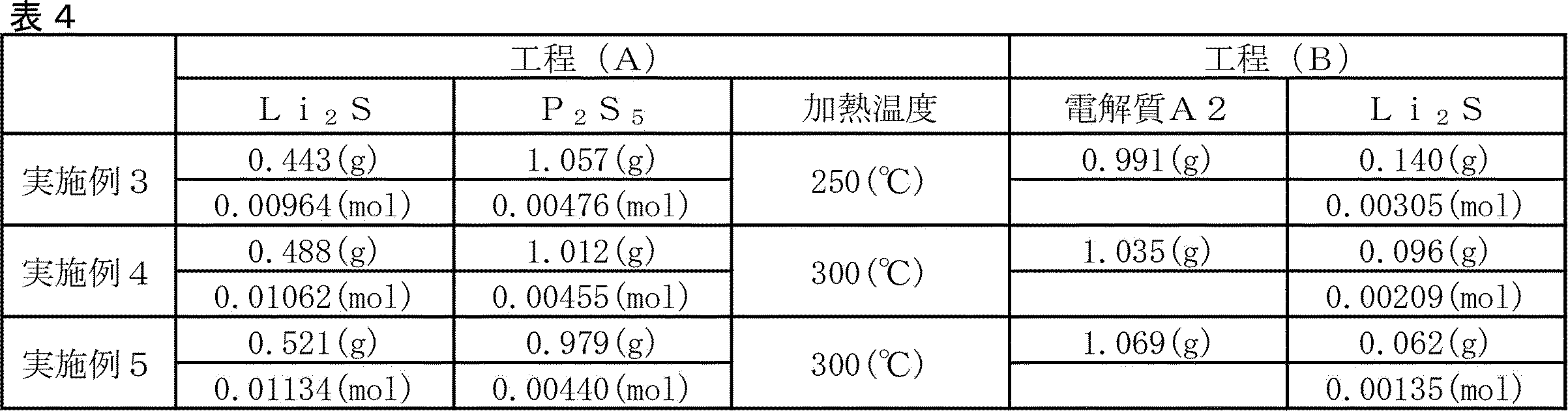
(参考例)
工程(A)
Li2Sを0.416g(0.00905mol)、P2S5を1.084g(0.00488mol)とした以外は実施例1(工程A)と同様にして非晶質固体電解質(A4)を得た。
工程(B)
工程(A)で得た非晶質固体電解質(A4)を0.966g量り取り、それにLi2Sを0.165g(0.00359mol)を添加し、更にハロゲン化リチウムとしてLiIを0.369g(0.00276mol)添加する以外は実施例1の工程(B)と同様にして非晶質固体電解質(B4)を得た。 (Reference example)
Process (A)
The amorphous solid electrolyte (A4) was used in the same manner as in Example 1 (Step A) except that Li 2 S was 0.416 g (0.00905 mol) and P 2 S 5 was 1.084 g (0.00488 mol). Obtained.
Process (B)
0.966 g of the amorphous solid electrolyte (A4) obtained in the step (A) was weighed, 0.165 g ( 0.00359 mol) of Li 2S was added thereto, and 0.369 g of Li I (Li I) as lithium halide was added. An amorphous solid electrolyte (B4) was obtained in the same manner as in the step (B) of Example 1 except that 0.00276 mol) was added.
加熱(結晶化)工程
工程(B)で得られた非晶質固体電解質(B4)の全量をアルゴン雰囲気としたグローブボックス内で、ホットプレートにて180℃で2時間加熱した。
その後、徐冷し、アルゴン雰囲気下のグローブボックス内で、乳鉢で粉砕して粉末(硫化物固体電解質ガラスセラミクス(参考例))を得た。
得られた粉末について、X線回折(XRD)測定によりチオリシコンリージョンII類似の結晶構造に由来するピークが観測され、結晶性固体電解質(ガラスセラミック)であることが確認できた。
(実施例6)
工程(B)
実施例2の加熱(結晶化)工程(1回目)で得られた粉末を1.051g量り取り、それにLi2Sを0.098g(0.00213mol)添加し、更にハロゲン化リチウムとしてLiIを0.213g(0.00159mol)及びLiBrを0.138g(86.845g/mol、0.00159mol)添加する以外は実施例2と同様にして非晶質固体電解質(B6)を得た。X線回折(XRD)測定の結果を図12に示す。 Heating (crystallization) step The whole amount of the amorphous solid electrolyte (B4) obtained in the step (B) was heated at 180 ° C. for 2 hours on a hot plate in a glove box having an argon atmosphere.
Then, it was slowly cooled and crushed in a mortar in a glove box under an argon atmosphere to obtain a powder (sulfide solid electrolyte glass ceramics (reference example)).
For the obtained powder, a peak derived from a crystal structure similar to that of Thiolicycon Region II was observed by X-ray diffraction (XRD) measurement, and it was confirmed that the powder was a crystalline solid electrolyte (glass ceramic).
(Example 6)
Process (B)
1.051 g of the powder obtained in the heating (crystallization) step (first time) of Example 2 was weighed, 0.098 g (0.00213 mol) of Li 2S was added thereto, and Li I was further reduced to 0 as lithium halide. An amorphous solid electrolyte (B6) was obtained in the same manner as in Example 2 except that 0.138 g (86.845 g / mol, 0.00159 mol) of 213 g (0.00159 mol) and LiBr was added. The result of the X-ray diffraction (XRD) measurement is shown in FIG.
加熱(結晶化)工程(2回目)
工程(B)で得られた非晶質固体電解質(B6)の全量をアルゴン雰囲気としたグローブボックス内で、ホットプレートにて175℃で2時間加熱した。
その後、徐冷し、アルゴン雰囲気下のグローブボックス内で、乳鉢で粉砕して粉末(硫化物固体電解質ガラスセラミクス(6))を得た。 Heating (crystallization) process (second time)
The whole amount of the amorphous solid electrolyte (B6) obtained in the step (B) was heated at 175 ° C. for 2 hours on a hot plate in a glove box having an argon atmosphere.
Then, it was slowly cooled and pulverized in a mortar in a glove box under an argon atmosphere to obtain a powder (sulfide solid electrolyte glass ceramics (6)).
得られた粉末についてX線回折(XRD)測定を行った(図13)。X線回折の結果、2θ=20.2°、23.6°にチオリシコンリージョンII類似の結晶構造に由来するピークが観測され、結晶性固体電解質(ガラスセラミック)であることが確認できた。示差熱(DTA)分析の結果を図14に示す。
X-ray diffraction (XRD) measurement was performed on the obtained powder (FIG. 13). As a result of X-ray diffraction, peaks derived from a crystal structure similar to Thioricicon Region II were observed at 2θ = 20.2 ° and 23.6 °, confirming that it was a crystalline solid electrolyte (glass ceramic). The results of differential thermal (DTA) analysis are shown in FIG.
(実施例7)
前記実施例4において、実施例4の加熱(結晶化)工程(1回目)で得られた粉末を0.987g量り取り、それにLi2Sを0.092g(0.00200mol)添加し、更にハロゲン化リチウムとしてLiIを0.214g(0.00160mol)及びLiBrを0.208g(0.00240mol)添加した以外は同様にして硫化物固体電解質ガラスセラミクス(7)を得た。 (Example 7)
In Example 4, 0.987 g of the powder obtained in the heating (crystallization) step (first time) of Example 4 was weighed, 0.092 g ( 0.00200 mol) of Li 2S was added thereto, and the halogen was further added. A sulfide solid electrolyte glass ceramics (7) was obtained in the same manner except that 0.214 g (0.00160 mol) of LiI and 0.208 g (0.00240 mol) of LiBr were added as lithium iodide.
(比較例3)
Li2Sを0.440g(0.00958mol)、P2S5を0.709g(0.00319mol)、LiIを0.213g(0.00159mol)、LiBrを0.138g(0.00159mol)添加する以外は比較例1と同様にして非晶質硫化物固体電解質(C2)を得た。 (Comparative Example 3)
Add 0.440 g (0.00958 mol) of Li 2 S, 0.709 g (0.00319 mol) of P 2 S 5 , 0.213 g (0.00159 mol) of Li I, and 0.138 g (0.00159 mol) of LiBr. An amorphous sulfide solid electrolyte (C2) was obtained in the same manner as in Comparative Example 1 except for the above.
結晶化工程
前記非晶質硫化物固体電解質(C2)の全量をアルゴン雰囲気としたグローブボックス内で、ホットプレートにて203℃で2時間加熱した。
その後、徐冷し、アルゴン雰囲気下のグローブボックス内で、乳鉢で粉砕して粉末(硫化物固体電解質ガラスセラミクス(C3))を得た。 Crystallization step The amorphous sulfide solid electrolyte (C2) was heated at 203 ° C. for 2 hours on a hot plate in a glove box having an argon atmosphere.
Then, it was slowly cooled and pulverized in a mortar in a glove box under an argon atmosphere to obtain a powder (sulfide solid electrolyte glass ceramics (C3)).
得られた粉末について、X線回折(XRD)測定によりチオリシコンリージョンII類似の結晶構造に由来するピークが観測され、結晶性固体電解質(ガラスセラミック)であることが確認できた。
硫化物固体電解質ガラスセラミクス(C3)の示差熱(DTA)分析の結果を図17に示す。 For the obtained powder, a peak derived from a crystal structure similar to that of Thiolicycon Region II was observed by X-ray diffraction (XRD) measurement, and it was confirmed that the powder was a crystalline solid electrolyte (glass ceramic).
The result of the differential thermal (DTA) analysis of the sulfide solid electrolyte glass ceramics (C3) is shown in FIG.
(比較例4)
Li2Sを0.440g(0.00958mol)、P2S5を0.709g(0.00319mol)、LiIを0.213g(0.00159mol)、LiBrを0.138g(0.00159mol)添加し、溶媒を使用せずにメカニカルミリングした以外は比較例2と同様にして非晶質硫化物固体電解質(C2)を得た。 (Comparative Example 4)
Add 0.440 g (0.00958 mol) of Li 2 S, 0.709 g (0.00319 mol) of P 2 S 5 , 0.213 g (0.00159 mol) of Li I, and 0.138 g (0.00159 mol) of LiBr. An amorphous sulfide solid electrolyte (C2) was obtained in the same manner as in Comparative Example 2 except that mechanical milling was performed without using a solvent.
(比較例5)
撹拌翼(アンカー翼)を備えた容量40Lの反応容器に、窒素雰囲気下で、シクロヘキサン25.5L、Li2Sを440g、P2S5を709g、LiBrを139g、LiIを213g及び極性溶媒のテトラメチルエチレンジアミン(TM
EDA)3.3Lを順に投入し、撹拌回転数80rpmで12日間の撹拌混合を継続して行った。
次いで、上記反応容器を、循環ポンプを備えたビーズミル(商品名:スターミルLME4、アシザワ・ファインテック社製、0.5mm径ジルコニア製ビーズを8.7kg充填)と接続し、ポンプ流量:2L/min、ビーズミル周速:12m/secの条件でビーズミルによる粉砕混合を4時間行い、電解質前駆体と極性溶媒とを含むスラリーを得た。
反応槽に投入したスラリーを、上記ビーズミル装置内のポンプを用いて600mL/分の流量で循環させ、周速10m/sでビーズミルの運転を開始し、ビーズミルの周速を12m/sとし、外部循環により温水(HW)を通水し、該ポンプの吐出の温度が70℃に保持されるように反応させた。次いで、反応後のスラリーを5Lシュレンク瓶に取り分け室温乾燥し、その後減圧下で110℃の加熱を行い、電解質前駆体に含まれる錯化剤を除去し、非晶性固体電解質を得た。 (Comparative Example 5)
In a reaction vessel with a capacity of 40 L equipped with a stirring blade (anchor blade), cyclohexane 25.5 L, Li 2 S 440 g, P 2 S 5 709 g, LiBr 139 g, Li I 213 g and a polar solvent under a nitrogen atmosphere. Tetramethylethylenediamine (TM
EDA) 3.3 L was added in order, and stirring and mixing was continued for 12 days at a stirring rotation speed of 80 rpm.
Next, the reaction vessel was connected to a bead mill equipped with a circulation pump (trade name: Star Mill LME4, manufactured by Ashizawa Finetech Co., Ltd., filled with 8.7 kg of 0.5 mm diameter zirconia beads), and the pump flow rate: 2 L / min. , Bead mill peripheral speed: Grinding and mixing with a bead mill for 4 hours under the condition of 12 m / sec to obtain a slurry containing an electrolyte precursor and a polar solvent.
The slurry charged into the reaction vessel was circulated at a flow rate of 600 mL / min using the pump in the bead mill device, the operation of the bead mill was started at a peripheral speed of 10 m / s, the peripheral speed of the bead mill was set to 12 m / s, and the outside was set. Hot water (HW) was passed by circulation and reacted so that the discharge temperature of the pump was maintained at 70 ° C. Next, the slurry after the reaction was placed in a 5 L Schlenk bottle, dried at room temperature, and then heated at 110 ° C. under reduced pressure to remove the complexing agent contained in the electrolyte precursor to obtain an amorphous solid electrolyte.
次いで、得られた非晶性硫化物固体電解質1gをアルゴン雰囲気としたグローブボックス内で、ホットプレートで180℃で2時間の加熱を行い、硫化物固体電解質ガラスセラミクス(C5)を得た。
Next, 1 g of the obtained amorphous sulfide solid electrolyte was heated at 180 ° C. for 2 hours on a hot plate in a glove box having an argon atmosphere to obtain sulfide solid electrolyte glass ceramics (C5).
(比較例6)
前記特許文献3の実施例8の記載を参考に硫化物固体電解質ガラスセラミクス(C6)を得た。 (Comparative Example 6)
A sulfide solid electrolyte glass ceramic (C6) was obtained with reference to the description of Example 8 of Patent Document 3.
前記特許文献3の実施例8の記載を参考に硫化物固体電解質ガラスセラミクス(C6)を得た。 (Comparative Example 6)
A sulfide solid electrolyte glass ceramic (C6) was obtained with reference to the description of Example 8 of Patent Document 3.
(比較例7)
前記特許文献2の実施例1の記載を参考に硫化物固体電解質ガラスセラミクス(C7)を得た。
実施例7で得られた硫化物固体電解質ガラスセラミクス(7)と比較するため、使用するLi2S、P2S5、LiI及びLiBrの量は実施例7とあわせた。 (Comparative Example 7)
A sulfide solid electrolyte glass ceramic (C7) was obtained with reference to the description of Example 1 of Patent Document 2.
The amounts of Li 2 S, P 2 S 5 , Li I and Li Br used were combined with Example 7 for comparison with the sulfide solid electrolyte glass ceramics (7) obtained in Example 7.
重複を避けるため実施例1以外では詳細な記載を控えたが、各実施例及び比較例で得られた硫化物固体電解質ガラスセラミクスの結晶子径、P2S6
4-リン比率、示差熱(DTA)分析による発熱ピーク温度と熱量、ILi2S/IP2S5、伝導度及びH2S発生量についても実施例1と同様に評価した(表5及び6)。比較例1及び2は実施例1に対応し、比較例3~6は実施例6に対応し、比較例7は実施例7に対応するものとなっている。
実施例2、6、比較例1、2、4及び7で得られた硫化物固体電解質ガラスセラミクスのD50及び不可逆容量を表7に示した。 In order to avoid duplication, detailed description is omitted except for Example 1, but the crystallite diameter, P2 S 6 4 - phosphorus ratio, and differential heat of the sulfide solid electrolyte glass ceramics obtained in each Example and Comparative Example ( The exothermic peak temperature and calorific value, I Li2S / IP2S5 , conductivity and H2S generation amount by DTA) analysis were also evaluated in the same manner as in Example 1 (Tables 5 and 6). Comparative Examples 1 and 2 correspond to Example 1, Comparative Examples 3 to 6 correspond to Example 6, and Comparative Example 7 corresponds to Example 7.
Table 7 shows the D50 and irreversible capacity of the sulfide solid electrolyte glass ceramics obtained in Examples 2 and 6 and Comparative Examples 1, 2, 4 and 7.

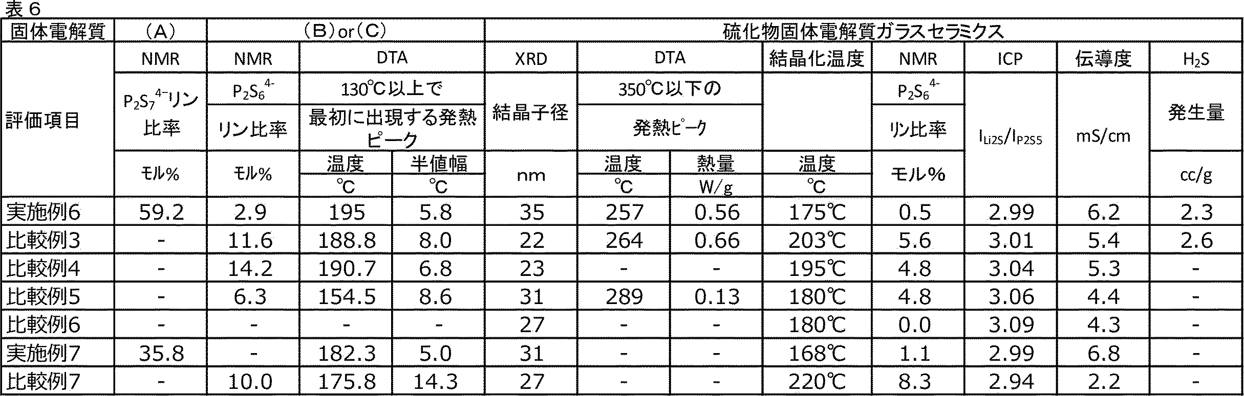
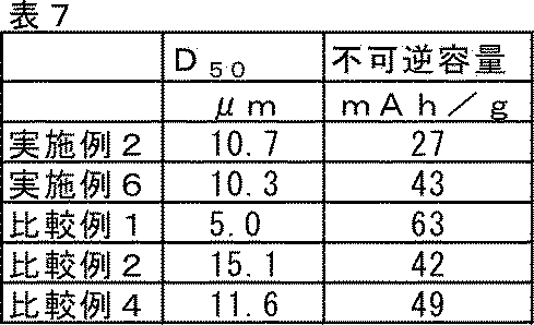
実施例1及び実施例2の硫化物固体電解質ガラスセラミクス(1)と比較して、結晶子径が小さく、P2S6
4-リン比率が多い比較例1及び2の硫化物固体電解質ガラスセラミクス(C1)及び(C2)は、イオン伝導度も小さいことが分かった。また、比較例1は実施例1に比べてH2S発生量も大きくなっていることが確認できた(表5)。
実施例2~5の硫化物固体電解質ガラスセラミクス(2)~(5)は、実施例1の硫化物固体電解質ガラスセラミクス(1)とは使用した原料の加熱温度や使用量が異なるものであるが、これらは実施例1の硫化物固体電解質ガラスセラミクス(1)と同様に優れた特性を有していることが確認できた(表5)。 Compared with the sulfide solid electrolyte glass ceramics (1) of Examples 1 and 2 , the crystallite diameter is small and the P2 S 6 4- phosphorus ratio is large. The sulfide solid electrolyte glass ceramics of Comparative Examples 1 and 2. It was found that (C1) and (C2) also had low ionic conductivity. Further, it was confirmed that the amount of H2S generated in Comparative Example 1 was larger than that in Example 1 (Table 5).
The sulfide solid electrolyte glass ceramics (2) to (5) of Examples 2 to 5 are different from the sulfide solid electrolyte glass ceramics (1) of Example 1 in the heating temperature and the amount of the raw materials used. However, it was confirmed that these had excellent properties similar to those of the sulfide solid electrolyte glass ceramics (1) of Example 1 (Table 5).
参考例は、P2S6
4-リン比率が多い硫化物固体電解質ガラスセラミクスの例であるが、P2S6
4-リン比率が多くなると、イオン伝導率が低下してしまうことが確認された。
The reference example is an example of sulfide solid electrolyte glass ceramics having a high P 2 S 6 4 -phosphorus ratio, but it was confirmed that the ionic conductivity decreases as the P 2 S 6 4- phosphorus ratio increases. rice field.
表6に示すように、比較例3~6は、実施例6と使用する原料が共通する。比較例3の硫化物固体電解質ガラスセラミクス(C3)は、結晶子径が小さなものであるが、P2S6
4-リン比率も多いため、イオン伝導度は低く、H2S発生量も劣るものとなった。比較例5及び6は前記の特許文献3に記載の製造方法を参考に製造した硫化物固体電解質ガラスセラミクスに対応する物であるが、いずれもイオン伝導度は改善の余地がある。
As shown in Table 6, Comparative Examples 3 to 6 share the same raw materials as Example 6. The sulfide solid electrolyte glass ceramics (C3) of Comparative Example 3 has a small crystallite diameter, but has a high P2 S 6 4- phosphorus ratio, so that the ionic conductivity is low and the amount of H 2 S generated is also inferior. It became a thing. Comparative Examples 5 and 6 correspond to the sulfide solid electrolyte glass ceramics produced with reference to the production method described in Patent Document 3, but there is room for improvement in ionic conductivity.
表6に示すように、比較例7は前記の特許文献2に記載の固体電解質に対応する硫化物固体電解質ガラスセラミクス(C7)であるが、これに対応する実施例7の硫化物固体電解質ガラスセラミクス(7)と比較して、イオン伝導度が低いものとなった。
As shown in Table 6, Comparative Example 7 is a sulfide solid electrolyte glass ceramics (C7) corresponding to the solid electrolyte described in Patent Document 2, but the sulfide solid electrolyte glass of Example 7 corresponding to this. Compared with the ceramics (7), the ionic conductivity was low.
表7に実施例2、6、比較例1、2、4で得られた硫化物固体電解質ガラスセラミクスの不可逆容量と平均粒子径(D50)の関係をまとめた。比較例1、2と比べて実施例2の結果は改善していることが確認できた。また、比較例4と比べて実施例6の結果は改善していることが確認できた。P2S6
4-リン比率が低下すると、不可逆容量は改善していることが確認でき、これは他の実施例、比較例及び参考例でも同様の傾向が確認できた。Liイオンをトラップし、電池の劣化を促進してしまうP2S6
4-リン比率が減ることで不可逆容量が改善したと推測される。
Table 7 summarizes the relationship between the irreversible capacity of the sulfide solid electrolyte glass ceramics obtained in Examples 2 and 6 and Comparative Examples 1, 2 and 4 and the average particle size (D 50 ). It was confirmed that the results of Example 2 were improved as compared with Comparative Examples 1 and 2. In addition, it was confirmed that the results of Example 6 were improved as compared with Comparative Example 4. It was confirmed that the irreversible capacity was improved when the P2 S 6 4 - phosphorus ratio decreased, and the same tendency was confirmed in other Examples, Comparative Examples and Reference Examples. It is presumed that the irreversible capacity was improved by reducing the P2 S 6 4 - phosphorus ratio, which traps Li ions and accelerates the deterioration of the battery.
本実施形態によれば、イオン伝導度が高く、電池性能に優れる結晶性硫化物固体電解質を製造することができる。本実施形態の製造方法により得られる結晶性硫化物固体電解質は、電池に、とりわけ、パソコン、ビデオカメラ、及び携帯電話等の情報関連機器や通信機器等に用いられる電池に好適に用いられる。
According to this embodiment, it is possible to produce a crystalline sulfide solid electrolyte having high ionic conductivity and excellent battery performance. The crystalline sulfide solid electrolyte obtained by the production method of the present embodiment is suitably used for batteries, particularly for batteries used in information-related devices such as personal computers, video cameras, mobile phones, and communication devices.
Claims (14)
- CuKα線を用いたX線回折(XRD)測定で、20.2°及び23.6°にピークを有し、結晶子径が30nm以上であり、固体31P-NMR測定から求められるP2S6 4-リン比率が、4.5モル%以下である、硫化物固体電解質ガラスセラミクス。 In X-ray diffraction (XRD) measurement using CuKα ray, it has peaks at 20.2 ° and 23.6 °, the crystallite diameter is 30 nm or more, and P 2 S obtained from solid 31 P-NMR measurement. 6 4 -Sulfurized solid electrolyte glass ceramics having a phosphorus ratio of 4.5 mol% or less.
- 示差熱分析(DTA)において、強度0.15W/g以上の結晶化発熱ピークを310℃以下に1つだけ有する、請求項1に記載の硫化物固体電解質ガラスセラミクス。 The sulfide solid electrolyte glass ceramics according to claim 1, which has only one crystallization exothermic peak having an intensity of 0.15 W / g or more at 310 ° C. or lower in a differential thermal analysis (DTA).
- 誘導結合プラズマ(ICP)発光分光分析装置で測定される元素比から計算されるLi2Sのモル分率(ILi2S)とP2S5のモル分率(IP2S5)との比(ILi2S/IP2S5)が、2.6以上、3.3以下である、請求項1又は2に記載の硫化物固体電解質ガラスセラミクス。 The ratio of the mole fraction of Li 2S (I Li 2S ) to the mole fraction of P 2 S 5 (I Li 2S 5 ) calculated from the elemental ratio measured by an inductively coupled plasma (ICP) emission spectroscopic analyzer (I Li 2S ) . / I P2S5 ) is 2.6 or more and 3.3 or less, the sulfide solid electrolyte glass ceramics according to claim 1 or 2.
- 硫化物固体電解質ガラスセラミクスの製造中間体である固体電解質(B)の固体31P-NMR測定から求められるP2S6 4-リン比率が、15.0モル%以下である、請求項1~3のいずれか1項に記載の硫化物固体電解質ガラスセラミクス。 Claims 1 to 1 to claim 1, wherein the P2 S 6 4- phosphorus ratio obtained from the solid 31 P - NMR measurement of the solid electrolyte (B), which is an intermediate for producing the sulfide solid electrolyte glass ceramics, is 15.0 mol% or less. 3. The sulfide solid electrolyte glass ceramics according to any one of 3.
- 硫化物固体電解質ガラスセラミクスの製造中間体である固体電解質(B)の示差熱分析(DTA)において、昇温過程で130℃以上の温度で最初に出現する発熱ピークの半値幅が8.0℃以下である、請求項1~4のいずれか1項に記載の硫化物固体電解質ガラスセラミクス。 In the differential thermal analysis (DTA) of the solid electrolyte (B), which is an intermediate for the production of sulfide solid electrolyte glass ceramics, the half-price range of the exothermic peak that first appears at a temperature of 130 ° C or higher during the temperature rise process is 8.0 ° C. The sulfide solid electrolyte glass ceramics according to any one of claims 1 to 4, which is as follows.
- リチウム原子、リン原子、硫黄原子及びハロゲン原子を含む、請求項1~5のいずれか1項に記載の硫化物固体電解質ガラスセラミクス。 The sulfide solid electrolyte glass ceramics according to any one of claims 1 to 5, which comprises a lithium atom, a phosphorus atom, a sulfur atom and a halogen atom.
- 前記ハロゲン原子が、塩素原子、臭素原子及びヨウ素原子から選ばれる少なくとも1種である、請求項6に記載の硫化物固体電解質ガラスセラミクス。 The sulfide solid electrolyte glass ceramics according to claim 6, wherein the halogen atom is at least one selected from a chlorine atom, a bromine atom and an iodine atom.
- Li2S及びP2S5を撹拌、混合及び粉砕から選ばれる少なくとも一種により処理し、固体電解質(A)を得る工程(A)と、
前記固体電解質(A)、Li2S及びハロゲン化リチウムを撹拌、混合及び粉砕から選ばれる少なくとも1種により処理し、固体電解質(B)を得る工程(B)と、
を含む、請求項1~7のいずれか1項に記載の硫化物固体電解質ガラスセラミクスの製造方法。 A step (A) of treating Li 2 S and P 2 S 5 with at least one selected from stirring, mixing and pulverization to obtain a solid electrolyte (A).
The step (B) of obtaining the solid electrolyte (B) by treating the solid electrolyte (A), Li 2S and lithium halide with at least one selected from stirring, mixing and pulverization.
The method for producing a sulfide solid electrolyte glass ceramic according to any one of claims 1 to 7, which comprises. - 前記固体電解質(A)がLi4P2S7を含有し、前記固体電解質(A)中の31P-NMRで測定されるP2S7 4-リン比率が、20.0モル%以上である、請求項8に記載の硫化物固体電解質ガラスセラミクスの製造方法。 When the solid electrolyte (A) contains Li 4 P 2 S 7 and the P 2 S 7 4- phosphorus ratio measured by 31 P-NMR in the solid electrolyte (A) is 20.0 mol% or more. The method for producing a sulfide solid electrolyte glass ceramics according to claim 8.
- 前記固体電解質(B)が、PS4 3-を主骨格とする、請求項8又は9に記載の硫化物固体電解質ガラスセラミクスの製造方法。 The method for producing a sulfide solid electrolyte glass ceramic according to claim 8 or 9, wherein the solid electrolyte (B) has PS 43 as a main skeleton.
- 前記固体電解質(B)を更に加熱すること、を含む、請求項8~10のいずれか1項に記載の硫化物固体電解質ガラスセラミクスの製造方法。 The method for producing a sulfide solid electrolyte glass ceramics according to any one of claims 8 to 10, which comprises further heating the solid electrolyte (B).
- 前記固体電解質(B)のDTA測定により130℃以上、かつ、最も低温側で観測される発熱ピークのピークトップ温度よりも5~30℃低い温度で前記固体電解質(B)を加熱する、請求項11に記載の硫化物固体電解質ガラスセラミクスの製造方法。 The claim that the solid electrolyte (B) is heated at a temperature of 130 ° C. or higher by the DTA measurement of the solid electrolyte (B) and 5 to 30 ° C. lower than the peak top temperature of the exothermic peak observed on the lowest temperature side. 11. The method for producing a sulfide solid electrolyte glass ceramics according to 11.
- 前記固体電解質(A)を更に加熱すること、を含む、請求項8~12のいずれか1項に記載の硫化物固体電解質ガラスセラミクスの製造方法。 The method for producing a sulfide solid electrolyte glass ceramics according to any one of claims 8 to 12, which comprises further heating the solid electrolyte (A).
- 請求項1~7のいずれか1項に記載の硫化物固体電解質ガラスセラミクスを用いた電池。 A battery using the sulfide solid electrolyte glass ceramics according to any one of claims 1 to 7.
Priority Applications (5)
| Application Number | Priority Date | Filing Date | Title |
|---|---|---|---|
| CN202180068224.4A CN116348427A (en) | 2020-10-09 | 2021-10-08 | Sulfide solid electrolyte glass ceramic and method for producing same |
| EP21877770.4A EP4227276A1 (en) | 2020-10-09 | 2021-10-08 | Sulfide solid electrolyte glass ceramic and manufacturing method for same |
| US18/030,286 US20230378525A1 (en) | 2020-10-09 | 2021-10-08 | Sulfide solid electrolyte glass ceramic and manufacturing method for same |
| JP2022555604A JPWO2022075471A1 (en) | 2020-10-09 | 2021-10-08 | |
| KR1020237011466A KR20230079084A (en) | 2020-10-09 | 2021-10-08 | Sulfide solid electrolyte glass ceramics and manufacturing method thereof |
Applications Claiming Priority (2)
| Application Number | Priority Date | Filing Date | Title |
|---|---|---|---|
| JP2020-171297 | 2020-10-09 | ||
| JP2020171297 | 2020-10-09 |
Publications (1)
| Publication Number | Publication Date |
|---|---|
| WO2022075471A1 true WO2022075471A1 (en) | 2022-04-14 |
Family
ID=81126080
Family Applications (1)
| Application Number | Title | Priority Date | Filing Date |
|---|---|---|---|
| PCT/JP2021/037459 WO2022075471A1 (en) | 2020-10-09 | 2021-10-08 | Sulfide solid electrolyte glass ceramic and manufacturing method for same |
Country Status (7)
| Country | Link |
|---|---|
| US (1) | US20230378525A1 (en) |
| EP (1) | EP4227276A1 (en) |
| JP (1) | JPWO2022075471A1 (en) |
| KR (1) | KR20230079084A (en) |
| CN (1) | CN116348427A (en) |
| TW (1) | TW202224248A (en) |
| WO (1) | WO2022075471A1 (en) |
Cited By (1)
| Publication number | Priority date | Publication date | Assignee | Title |
|---|---|---|---|---|
| WO2024029480A1 (en) * | 2022-08-03 | 2024-02-08 | 出光興産株式会社 | Glass-ceramics solid electrolyte and lithium-ion battery |
Citations (3)
| Publication number | Priority date | Publication date | Assignee | Title |
|---|---|---|---|---|
| JP2013016423A (en) | 2011-07-06 | 2013-01-24 | Toyota Motor Corp | Solid sulfide electrolyte material, solid-state lithium battery, and method for manufacturing solid sulfide electrolyte material |
| WO2018225526A1 (en) | 2017-06-09 | 2018-12-13 | 出光興産株式会社 | Method for producing sulfide solid electrolyte |
| JP2019200856A (en) * | 2018-05-14 | 2019-11-21 | 三星電子株式会社Samsung Electronics Co.,Ltd. | Method of preparing sulfide-based solid electrolyte, and method of preparing all-solid secondary battery |
Family Cites Families (3)
| Publication number | Priority date | Publication date | Assignee | Title |
|---|---|---|---|---|
| JP2014089971A (en) | 2013-12-18 | 2014-05-15 | Toyota Motor Corp | Sulfide solid electrolytic material, lithium solid battery, and manufacturing method of sulfide solid electrolytic material |
| JP2019200851A (en) | 2018-05-14 | 2019-11-21 | トヨタ自動車株式会社 | Solid electrolyte, all-solid-state battery and method for producing solid electrolyte |
| EP3886122A4 (en) | 2018-11-22 | 2022-08-10 | Idemitsu Kosan Co.,Ltd. | Method for producing solid electrolyte, and electrolyte precursor |
-
2021
- 2021-10-08 WO PCT/JP2021/037459 patent/WO2022075471A1/en unknown
- 2021-10-08 US US18/030,286 patent/US20230378525A1/en active Pending
- 2021-10-08 TW TW110137645A patent/TW202224248A/en unknown
- 2021-10-08 EP EP21877770.4A patent/EP4227276A1/en active Pending
- 2021-10-08 CN CN202180068224.4A patent/CN116348427A/en active Pending
- 2021-10-08 JP JP2022555604A patent/JPWO2022075471A1/ja active Pending
- 2021-10-08 KR KR1020237011466A patent/KR20230079084A/en unknown
Patent Citations (3)
| Publication number | Priority date | Publication date | Assignee | Title |
|---|---|---|---|---|
| JP2013016423A (en) | 2011-07-06 | 2013-01-24 | Toyota Motor Corp | Solid sulfide electrolyte material, solid-state lithium battery, and method for manufacturing solid sulfide electrolyte material |
| WO2018225526A1 (en) | 2017-06-09 | 2018-12-13 | 出光興産株式会社 | Method for producing sulfide solid electrolyte |
| JP2019200856A (en) * | 2018-05-14 | 2019-11-21 | 三星電子株式会社Samsung Electronics Co.,Ltd. | Method of preparing sulfide-based solid electrolyte, and method of preparing all-solid secondary battery |
Non-Patent Citations (2)
| Title |
|---|
| KANNO ET AL., JOURNAL OF THE ELECTROCHEMICAL SOCIETY, vol. 148, no. 7, 2001, pages A742 - 746 |
| SOLID STATE IONICS, vol. 177, 2006, pages 2721 - 2725 |
Cited By (1)
| Publication number | Priority date | Publication date | Assignee | Title |
|---|---|---|---|---|
| WO2024029480A1 (en) * | 2022-08-03 | 2024-02-08 | 出光興産株式会社 | Glass-ceramics solid electrolyte and lithium-ion battery |
Also Published As
| Publication number | Publication date |
|---|---|
| KR20230079084A (en) | 2023-06-05 |
| EP4227276A1 (en) | 2023-08-16 |
| JPWO2022075471A1 (en) | 2022-04-14 |
| US20230378525A1 (en) | 2023-11-23 |
| TW202224248A (en) | 2022-06-16 |
| CN116348427A (en) | 2023-06-27 |
Similar Documents
| Publication | Publication Date | Title |
|---|---|---|
| JP7178452B2 (en) | sulfide solid electrolyte | |
| KR102605002B1 (en) | Sulfide solid electrolyte | |
| Yi et al. | Sub-micrometric Li4− xNaxTi5O12 (0≤ x≤ 0.2) spinel as anode material exhibiting high rate capability | |
| JP6719037B1 (en) | Method for producing solid electrolyte and electrolyte precursor | |
| Kaliyappan et al. | High tap density Co and Ni containing P2‐Na0. 66MnO2 buckyballs: a promising high voltage cathode for stable sodium‐ion batteries | |
| Li et al. | Synthesis and characterization of Mo-doped LiNi0. 5Co0. 2Mn0. 3O2 cathode materials prepared by a hydrothermal process | |
| EP4163997A1 (en) | Positive electrode active material for lithium ion secondary batteries, method for producing said positive electrode active material, and lithium ion secondary battery | |
| JP7324849B2 (en) | Electrode mixture and its manufacturing method | |
| WO2021100874A1 (en) | Method for producing sulfide solid electrolyte | |
| Brog et al. | Characteristics and properties of nano-LiCoO 2 synthesized by pre-organized single source precursors: Li-ion diffusivity, electrochemistry and biological assessment | |
| WO2022075471A1 (en) | Sulfide solid electrolyte glass ceramic and manufacturing method for same | |
| Xu et al. | Li2NiO2F a new oxyfluoride disordered rocksalt cathode material | |
| WO2023127736A1 (en) | Composite active material | |
| US11973185B2 (en) | Method for producing sulfide solid electrolyte | |
| WO2023190862A1 (en) | Sulfide solid electrolyte glass ceramic and manufacturing method for same | |
| US20240083748A1 (en) | Method for producing solid electrolyte | |
| WO2021240913A1 (en) | Electrode mixture and method for producing same | |
| WO2022163648A1 (en) | Modified sulfide solid electrolyte and manufacturing method therefor | |
| EP4339970A1 (en) | Sulfide solid electrolyte composition, electrode mixture containing same, and method for producing sulfide solid electrolyte composition | |
| US20230335716A1 (en) | Active material and method for producing same, electrode mixture, and battery | |
| CN116635333A (en) | Positive electrode active material for rechargeable battery | |
| JP2023097070A (en) | Method of manufacturing sulfide solid electrolyte and method of manufacturing electrode mixture | |
| JP2023152966A (en) | Solid sulfide electrolyte, method for producing the same, electrode composite and lithium-ion battery | |
| Brog et al. | Characteristics and properties of nano-LiCoO | |
| Xu et al. | Niobium-Doped Titanium Dioxide with High Dopant |
Legal Events
| Date | Code | Title | Description |
|---|---|---|---|
| 121 | Ep: the epo has been informed by wipo that ep was designated in this application |
Ref document number: 21877770 Country of ref document: EP Kind code of ref document: A1 |
|
| ENP | Entry into the national phase |
Ref document number: 2022555604 Country of ref document: JP Kind code of ref document: A |
|
| NENP | Non-entry into the national phase |
Ref country code: DE |
|
| ENP | Entry into the national phase |
Ref document number: 2021877770 Country of ref document: EP Effective date: 20230509 |