WO2022075011A1 - Shock absorber - Google Patents
Shock absorber Download PDFInfo
- Publication number
- WO2022075011A1 WO2022075011A1 PCT/JP2021/033574 JP2021033574W WO2022075011A1 WO 2022075011 A1 WO2022075011 A1 WO 2022075011A1 JP 2021033574 W JP2021033574 W JP 2021033574W WO 2022075011 A1 WO2022075011 A1 WO 2022075011A1
- Authority
- WO
- WIPO (PCT)
- Prior art keywords
- chamber
- back pressure
- valve
- orifice
- passage
- Prior art date
Links
- 239000006096 absorbing agent Substances 0.000 title claims description 32
- 230000035939 shock Effects 0.000 title claims description 32
- 238000011144 upstream manufacturing Methods 0.000 claims abstract description 74
- 239000012530 fluid Substances 0.000 claims description 99
- 238000004891 communication Methods 0.000 claims description 26
- 238000013016 damping Methods 0.000 abstract description 32
- 230000003111 delayed effect Effects 0.000 abstract description 7
- 230000008602 contraction Effects 0.000 description 159
- 230000002093 peripheral effect Effects 0.000 description 66
- 125000006850 spacer group Chemical group 0.000 description 6
- 230000000694 effects Effects 0.000 description 5
- 238000012856 packing Methods 0.000 description 4
- 238000000034 method Methods 0.000 description 3
- 238000003825 pressing Methods 0.000 description 3
- 238000012545 processing Methods 0.000 description 3
- 230000008878 coupling Effects 0.000 description 2
- 238000010168 coupling process Methods 0.000 description 2
- 238000005859 coupling reaction Methods 0.000 description 2
- 238000003780 insertion Methods 0.000 description 2
- 230000037431 insertion Effects 0.000 description 2
- 238000007789 sealing Methods 0.000 description 2
- 230000006835 compression Effects 0.000 description 1
- 238000007906 compression Methods 0.000 description 1
- 230000007423 decrease Effects 0.000 description 1
- 230000001934 delay Effects 0.000 description 1
- 238000004519 manufacturing process Methods 0.000 description 1
- 238000007639 printing Methods 0.000 description 1
- 239000007787 solid Substances 0.000 description 1
Images


Classifications
-
- F—MECHANICAL ENGINEERING; LIGHTING; HEATING; WEAPONS; BLASTING
- F16—ENGINEERING ELEMENTS AND UNITS; GENERAL MEASURES FOR PRODUCING AND MAINTAINING EFFECTIVE FUNCTIONING OF MACHINES OR INSTALLATIONS; THERMAL INSULATION IN GENERAL
- F16F—SPRINGS; SHOCK-ABSORBERS; MEANS FOR DAMPING VIBRATION
- F16F9/00—Springs, vibration-dampers, shock-absorbers, or similarly-constructed movement-dampers using a fluid or the equivalent as damping medium
- F16F9/32—Details
- F16F9/34—Special valve constructions; Shape or construction of throttling passages
- F16F9/348—Throttling passages in the form of annular discs or other plate-like elements which may or may not have a spring action, operating in opposite directions or singly, e.g. annular discs positioned on top of the valve or piston body
- F16F9/3488—Throttling passages in the form of annular discs or other plate-like elements which may or may not have a spring action, operating in opposite directions or singly, e.g. annular discs positioned on top of the valve or piston body characterised by features intended to affect valve bias or pre-stress
-
- F—MECHANICAL ENGINEERING; LIGHTING; HEATING; WEAPONS; BLASTING
- F16—ENGINEERING ELEMENTS AND UNITS; GENERAL MEASURES FOR PRODUCING AND MAINTAINING EFFECTIVE FUNCTIONING OF MACHINES OR INSTALLATIONS; THERMAL INSULATION IN GENERAL
- F16F—SPRINGS; SHOCK-ABSORBERS; MEANS FOR DAMPING VIBRATION
- F16F9/00—Springs, vibration-dampers, shock-absorbers, or similarly-constructed movement-dampers using a fluid or the equivalent as damping medium
- F16F9/32—Details
- F16F9/34—Special valve constructions; Shape or construction of throttling passages
- F16F9/348—Throttling passages in the form of annular discs or other plate-like elements which may or may not have a spring action, operating in opposite directions or singly, e.g. annular discs positioned on top of the valve or piston body
-
- F—MECHANICAL ENGINEERING; LIGHTING; HEATING; WEAPONS; BLASTING
- F16—ENGINEERING ELEMENTS AND UNITS; GENERAL MEASURES FOR PRODUCING AND MAINTAINING EFFECTIVE FUNCTIONING OF MACHINES OR INSTALLATIONS; THERMAL INSULATION IN GENERAL
- F16F—SPRINGS; SHOCK-ABSORBERS; MEANS FOR DAMPING VIBRATION
- F16F9/00—Springs, vibration-dampers, shock-absorbers, or similarly-constructed movement-dampers using a fluid or the equivalent as damping medium
- F16F9/10—Springs, vibration-dampers, shock-absorbers, or similarly-constructed movement-dampers using a fluid or the equivalent as damping medium using liquid only; using a fluid of which the nature is immaterial
- F16F9/14—Devices with one or more members, e.g. pistons, vanes, moving to and fro in chambers and using throttling effect
- F16F9/16—Devices with one or more members, e.g. pistons, vanes, moving to and fro in chambers and using throttling effect involving only straight-line movement of the effective parts
- F16F9/18—Devices with one or more members, e.g. pistons, vanes, moving to and fro in chambers and using throttling effect involving only straight-line movement of the effective parts with a closed cylinder and a piston separating two or more working spaces therein
- F16F9/19—Devices with one or more members, e.g. pistons, vanes, moving to and fro in chambers and using throttling effect involving only straight-line movement of the effective parts with a closed cylinder and a piston separating two or more working spaces therein with a single cylinder and of single-tube type
-
- F—MECHANICAL ENGINEERING; LIGHTING; HEATING; WEAPONS; BLASTING
- F16—ENGINEERING ELEMENTS AND UNITS; GENERAL MEASURES FOR PRODUCING AND MAINTAINING EFFECTIVE FUNCTIONING OF MACHINES OR INSTALLATIONS; THERMAL INSULATION IN GENERAL
- F16F—SPRINGS; SHOCK-ABSORBERS; MEANS FOR DAMPING VIBRATION
- F16F9/00—Springs, vibration-dampers, shock-absorbers, or similarly-constructed movement-dampers using a fluid or the equivalent as damping medium
- F16F9/32—Details
- F16F9/44—Means on or in the damper for manual or non-automatic adjustment; such means combined with temperature correction
- F16F9/46—Means on or in the damper for manual or non-automatic adjustment; such means combined with temperature correction allowing control from a distance, i.e. location of means for control input being remote from site of valves, e.g. on damper external wall
- F16F9/465—Means on or in the damper for manual or non-automatic adjustment; such means combined with temperature correction allowing control from a distance, i.e. location of means for control input being remote from site of valves, e.g. on damper external wall using servo control, the servo pressure being created by the flow of damping fluid, e.g. controlling pressure in a chamber downstream of a pilot passage
-
- F—MECHANICAL ENGINEERING; LIGHTING; HEATING; WEAPONS; BLASTING
- F16—ENGINEERING ELEMENTS AND UNITS; GENERAL MEASURES FOR PRODUCING AND MAINTAINING EFFECTIVE FUNCTIONING OF MACHINES OR INSTALLATIONS; THERMAL INSULATION IN GENERAL
- F16F—SPRINGS; SHOCK-ABSORBERS; MEANS FOR DAMPING VIBRATION
- F16F9/00—Springs, vibration-dampers, shock-absorbers, or similarly-constructed movement-dampers using a fluid or the equivalent as damping medium
- F16F9/32—Details
- F16F9/50—Special means providing automatic damping adjustment, i.e. self-adjustment of damping by particular sliding movements of a valve element, other than flexions or displacement of valve discs; Special means providing self-adjustment of spring characteristics
- F16F9/512—Means responsive to load action, i.e. static load on the damper or dynamic fluid pressure changes in the damper, e.g. due to changes in velocity
-
- F—MECHANICAL ENGINEERING; LIGHTING; HEATING; WEAPONS; BLASTING
- F16—ENGINEERING ELEMENTS AND UNITS; GENERAL MEASURES FOR PRODUCING AND MAINTAINING EFFECTIVE FUNCTIONING OF MACHINES OR INSTALLATIONS; THERMAL INSULATION IN GENERAL
- F16F—SPRINGS; SHOCK-ABSORBERS; MEANS FOR DAMPING VIBRATION
- F16F9/00—Springs, vibration-dampers, shock-absorbers, or similarly-constructed movement-dampers using a fluid or the equivalent as damping medium
- F16F9/32—Details
- F16F9/50—Special means providing automatic damping adjustment, i.e. self-adjustment of damping by particular sliding movements of a valve element, other than flexions or displacement of valve discs; Special means providing self-adjustment of spring characteristics
- F16F9/516—Special means providing automatic damping adjustment, i.e. self-adjustment of damping by particular sliding movements of a valve element, other than flexions or displacement of valve discs; Special means providing self-adjustment of spring characteristics resulting in the damping effects during contraction being different from the damping effects during extension, i.e. responsive to the direction of movement
-
- F—MECHANICAL ENGINEERING; LIGHTING; HEATING; WEAPONS; BLASTING
- F16—ENGINEERING ELEMENTS AND UNITS; GENERAL MEASURES FOR PRODUCING AND MAINTAINING EFFECTIVE FUNCTIONING OF MACHINES OR INSTALLATIONS; THERMAL INSULATION IN GENERAL
- F16F—SPRINGS; SHOCK-ABSORBERS; MEANS FOR DAMPING VIBRATION
- F16F2222/00—Special physical effects, e.g. nature of damping effects
- F16F2222/12—Fluid damping
-
- F—MECHANICAL ENGINEERING; LIGHTING; HEATING; WEAPONS; BLASTING
- F16—ENGINEERING ELEMENTS AND UNITS; GENERAL MEASURES FOR PRODUCING AND MAINTAINING EFFECTIVE FUNCTIONING OF MACHINES OR INSTALLATIONS; THERMAL INSULATION IN GENERAL
- F16F—SPRINGS; SHOCK-ABSORBERS; MEANS FOR DAMPING VIBRATION
- F16F2228/00—Functional characteristics, e.g. variability, frequency-dependence
- F16F2228/06—Stiffness
- F16F2228/066—Variable stiffness
-
- F—MECHANICAL ENGINEERING; LIGHTING; HEATING; WEAPONS; BLASTING
- F16—ENGINEERING ELEMENTS AND UNITS; GENERAL MEASURES FOR PRODUCING AND MAINTAINING EFFECTIVE FUNCTIONING OF MACHINES OR INSTALLATIONS; THERMAL INSULATION IN GENERAL
- F16F—SPRINGS; SHOCK-ABSORBERS; MEANS FOR DAMPING VIBRATION
- F16F2232/00—Nature of movement
- F16F2232/08—Linear
-
- F—MECHANICAL ENGINEERING; LIGHTING; HEATING; WEAPONS; BLASTING
- F16—ENGINEERING ELEMENTS AND UNITS; GENERAL MEASURES FOR PRODUCING AND MAINTAINING EFFECTIVE FUNCTIONING OF MACHINES OR INSTALLATIONS; THERMAL INSULATION IN GENERAL
- F16F—SPRINGS; SHOCK-ABSORBERS; MEANS FOR DAMPING VIBRATION
- F16F2234/00—Shape
- F16F2234/02—Shape cylindrical
Definitions
- the present invention relates to a damping force adjusting shock absorber that controls the flow of working fluid with respect to the stroke of the piston rod to adjust the damping force.
- Patent Document 1 a working fluid is introduced from the upstream chamber to the back pressure chamber by a back pressure introduction passage in order to prevent the main valve of the upstream chamber from opening when the piston moves in one direction.
- a damping force-adjustable hydraulic shock absorber (hereinafter referred to as "conventional shock absorber”) is disclosed.
- This back pressure introduction passage is formed by forming a through hole in the valve member (pilot case) that penetrates the valve member in the axial direction.
- the flow path area of the back pressure introduction passage may be made small, in other words, the hole diameter of the through hole may be made small (for example, “0.6 mm”).
- the hole diameter of the through hole may be made small (for example, “0.6 mm”).
- An object of the present invention is to provide a shock absorber that suppresses overshoot of damping force.
- the shock absorber of the present invention has a cylinder in which a working fluid is sealed, a piston that is slidably inserted into the cylinder and divides the inside of the cylinder into two chambers, and is connected to the piston to the outside of the cylinder. Resistance to the extended piston rod, the passage through which the working fluid flows as the piston moves in one direction, and the flow of the working fluid in the passage from the upstream chamber to the downstream chamber.
- the main valve is composed of a main valve that applies an internal pressure, a back pressure chamber that exerts an internal pressure in the valve closing direction of the main valve, and a tubular portion and a bottom portion having an opening at one end. The main valve is arranged in the opening and is inside.
- a downstream back pressure introduction passage in which a working fluid flows to the back pressure chamber, and a seat portion formed inside the bottom of the case member and defining a pressure receiving chamber that communicates with the downstream back pressure introduction passage.
- a check valve that is seated on the seat portion and allows the flow of working fluid from the downstream side back pressure introduction passage to the back pressure chamber, and a communication passage that communicates the downstream side chamber and the back pressure chamber. It has a first orifice that is provided and has a minimum flow path area in the communication passage, and a second orifice that is provided in the upstream side back pressure introduction passage and has a flow path area larger than that of the first orifice. It is a feature. Further, the shock absorber of the present invention is connected to a cylinder in which a working fluid is sealed, a piston that is slidably inserted into the cylinder and divides the inside of the cylinder into two chambers, and the cylinder.
- the passage in which the working fluid flows due to the movement of the piston in one direction, and the flow of the working fluid in the passage from the upstream chamber to the downstream chamber It consists of a main valve that imparts resistance, a back pressure chamber that exerts internal pressure in the valve closing direction of the main valve, a cylinder portion having an opening at one end, and a bottom portion, and the main valve is arranged in the opening.
- the second seat portion formed on the bottom of the case member and surrounding the opening of the downstream side back pressure introduction passage, and the first seat portion and the second seat portion are seated by the pressure of the back pressure chamber.
- FIG. 10 is an enlarged view showing an extension side damping force variable mechanism portion.
- FIG. 10 is an enlarged view showing a compression side damping force variable mechanism portion in FIG. 10. It is sectional drawing by the axial plane of the main part of the shock absorber in 5th Embodiment. It is sectional drawing by the axial plane of the main part of the shock absorber in 6th Embodiment.
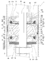
- the shock absorber 1 is a damping force adjusting type shock absorber having a damping force adjusting mechanism built in the cylinder 2.
- a piston 3 is slidably fitted in the cylinder 2.
- the piston 3 divides the inside of the cylinder 2 into two chambers, a cylinder upper chamber 2A and a cylinder lower chamber 2B.
- a free piston (not shown) that can move vertically in the cylinder 2 is provided in the cylinder 2, and the free piston has a cylinder lower chamber 2B and a bottom on the piston 3 side (upper side) in the cylinder 2. It is divided into a gas chamber (not shown) on the side (lower side).
- a small diameter portion 18 formed at the lower end of the piston rod 10 is inserted into the shaft hole 4 of the piston 3.
- the upper end side of the piston rod 10 extends to the outside of the cylinder 2.
- the piston 3 is provided with an extension-side passage 19 whose upper end opens into the cylinder upper chamber 2A and a contraction-side passage 20 whose lower end opens into the cylinder lower chamber 2B.
- An extension side valve mechanism 21 for controlling the flow of the working fluid in the extension side passage 19 is provided on the lower end side of the piston 3.
- a contraction-side valve mechanism 51 for controlling the flow of the working fluid in the contraction-side passage 20 is provided on the upper end side of the piston 3.
- the extension side valve mechanism 21 has a bottomed cylindrical extension side pilot case 22 (case member) attached to the small diameter portion 18 of the piston rod 10.
- the extension side pilot case 22 is composed of a cylindrical portion 26 (cylinder portion) having an opening 28 (see FIG. 3) on the piston 3 side (one end) and a bottom portion 27, and the extension side main valve 23 is arranged in the opening 28.
- the extension side valve mechanism 21 includes a seat portion 24 formed on the outer peripheral side of the lower end surface of the piston 3 so that the extension side main valve 23 can be detached and seated, and the back surface of the extension side pilot case 22 and the extension side main valve 23.
- the extension side back pressure chamber 25 formed between the two is provided.
- the pressure in the extension side back pressure chamber 25 acts on the extension side main valve 23 in the valve closing direction.
- the extension-side main valve 23 is a packing valve in which an annular packing 31 made of an elastic body comes into contact with the inner peripheral surface (cylinder portion) of the extension-side pilot case 22 over the entire circumference.
- the extension side back pressure chamber 25 has an annular shape defined by an extension side back pressure introduction passage (upstream side back pressure introduction passage) from the cylinder upper chamber 2A (upstream side chamber), that is, an extension side passage 19 and a seat portion 24.
- the working fluid is introduced through the extension side main pressure receiving chamber 160, the orifice 152 provided in the retainer 151, and the orifice 153 (second orifice) provided in the extension side main valve 23.
- the retainer 151 is provided between the piston 3 and the extension side main valve 23.
- the extension-side back pressure chamber 25 communicates with the cylinder lower chamber 2B via a passage 32 and a sub-valve 30 formed in the bottom portion 27 of the extension-side pilot case 22.
- the sub-valve 30 opens when the pressure of the extension-side back pressure chamber 25 reaches a predetermined pressure, and with respect to the flow of working fluid from the extension-side back pressure chamber 25 to the cylinder lower chamber 2B (downstream-side chamber). To give resistance.
- the extension side back pressure chamber 25 communicates with the first pressure receiving chamber 154 formed between the extension side pilot case 22 and the sub valve 30 via the passage 32.
- the first pressure receiving chamber 154 is an endless first seat portion 156 provided on the lower end surface 155 of the extension side pilot case 22 (the surface opposite to the extension side main valve 23 side). It is divided into a fan shape. Inside the first seat portion 156, a seat portion 157 on which the sub valve 30 is seated is provided inside the first seat portion 156. The aisle 32 opens between the seat portion 157 and the arc-shaped outer peripheral portion 158 of the first seat portion 156 on the lower end surface 155.
- a plurality of (“5” in the first embodiment) first pressure receiving chambers 154 are provided at equal intervals on the lower end surface 155 of the extension side pilot case 22 in the circumferential direction.
- the extension side back pressure chamber 25 is moved from the cylinder lower chamber 2B (the chamber on the upstream side) to the extension side back pressure chamber 25 by the movement of the piston 3 in the contraction direction (other direction).
- a back pressure introduction passage 161 downstream side back pressure introduction passage in which a flow of working fluid is generated is provided.
- An annular seat portion 35 is provided on the upper end surface 162 of the extension side pilot case 22 (the surface on the extension side main valve 23 side, see FIG. 3).
- the seat portion 35 defines an annular pressure receiving chamber 164 provided on the outer periphery of the inner peripheral portion of the bottom portion 27.
- the height of the seat portion 35 is the same as the height of the upper end surface of the inner peripheral portion of the bottom portion 27 in the axial direction (“vertical direction” in FIG. 3).
- a disk-shaped check valve 33 that allows the flow of working fluid from the back pressure introduction passage 161 to the extension side back pressure chamber 25 abuts on the seat portion 35 so as to be able to take off and sit.
- the inner peripheral portion of the check valve 33, the spacer 166, in order from the extension-side pilot case 22 side to the piston 3 side The inner peripheral portion of the extension side main valve 23 and the retainer 151 are interposed.
- a second pressure receiving chamber 167 isolated from the first pressure receiving chamber 154 is provided on the lower end surface 155 of the extension side pilot case 22.
- the back pressure introduction passage 161 (downstream side back pressure introduction passage) opens in the second pressure receiving chamber 167.
- the second pressure receiving chamber 167 is defined by a second seat portion 168 (sub valve seat portion).
- the second seat portion 168 extends in an arc shape between a pair of adjacent first pressure receiving chambers 154 (first seat portion 156).
- the second seat portion 168, the seat portion 35, and the first seat portion 156 are in order from the shortest. Further, as shown in FIG. 3, the extension side pilot case 22 on the lower end surface of the inner peripheral portion of the bottom portion 27 of the first seat portion 156, the second seat portion 168, the seat portion 157, and the extension side pilot case 22. The height from the lower end surface 155 is the same.
- the second seat portion 168 is provided with a first orifice 169 that communicates the second pressure receiving chamber 167 and the cylinder lower chamber 2B (the chamber on the downstream side).
- the flow path area of the first orifice 169 is smaller than the flow path area of the orifice 152 and the orifice 153 (second orifice) provided in the extension side back pressure introduction passage (upstream side back pressure introduction passage).
- the first orifice 169 is formed by applying pressure processing (coining) to the end surface (the surface on which the sub valve 30 is seated) of the second seat portion 168.
- the extension side valve mechanism 21 is formed with an extension side communication passage (communication passage) that communicates the cylinder lower chamber 2B and the extension side back pressure chamber 25.
- the extension-side communication passage allows the working fluid of the cylinder lower chamber 2B (the chamber that becomes the upstream side due to the movement of the piston in the other direction) by moving the piston 3 in the contraction direction (other direction) to the first orifice 169, first. 2 It is introduced into the extension side back pressure chamber 25 via the pressure receiving chamber 167, the back pressure introduction passage 161 (downstream side back pressure introduction passage), the pressure receiving chamber 164, and the check valve 33. Further, the working fluid introduced into the extension side back pressure chamber 25 is the extension side back pressure introduction passage (upstream side back pressure introduction passage), that is, the orifice 153 (second orifice), the orifice 152, and the extension side main pressure receiving chamber 160.
- the extension side back pressure introduction passage upstream side back pressure introduction passage
- the flow path area of the first orifice 169 is smaller than the minimum flow path area in the extension side continuous passage and the minimum flow path area in the extension side back pressure introduction passage.
- the contraction side valve mechanism 51 has a bottomed cylindrical contraction side pilot case 52 (case member) attached to the small diameter portion 18 of the piston rod 10.
- the contraction side pilot case 52 is composed of a cylindrical portion 56 (cylinder portion) having an opening 58 (see FIG. 3) on the piston 3 side (one end) and a bottom portion 57, and the contraction side main valve 53 is arranged in the opening portion 58.
- the contraction side valve mechanism 51 includes a seat portion 54 formed on the outer peripheral side of the upper end surface of the piston 3 so that the contraction side main valve 53 can be taken off and seated, and the contraction side pilot case 52 and the back surface of the contraction side main valve 53.
- a contraction-side back pressure chamber 55 formed between the two is provided.
- the pressure in the contraction side back pressure chamber 55 acts on the contraction side main valve 53 in the valve closing direction.
- the contraction side main valve 53 is a packing valve in which an annular packing 61 made of an elastic body comes into contact with the inner peripheral surface (cylinder portion) of the contraction side pilot case 52 over the entire circumference.
- the contraction side back pressure chamber 55 has an annular shape defined by a contraction side back pressure introduction passage (upstream side back pressure introduction passage) from the cylinder lower chamber 2B (upstream side chamber), that is, a contraction side passage 20 and a seat portion 54.
- the working fluid is introduced through the contraction side main pressure receiving chamber 180, the orifice 172 provided in the retainer 171 and the orifice 173 (second orifice) provided in the contraction side main valve 53.
- the retainer 171 is provided between the piston 3 and the contraction side main valve 53.
- the contraction side back pressure chamber 55 communicates with the cylinder upper chamber 2A via a passage 62 and a sub valve 60 formed in the contraction side pilot case 52.
- the sub-valve 60 is opened when the pressure of the contraction side back pressure chamber 55 reaches a predetermined pressure, and the working fluid flows from the contraction side back pressure chamber 55 to the cylinder upper chamber 2A (downstream side chamber). To give resistance.
- the contraction side back pressure chamber 55 communicates with the first pressure receiving chamber 174 formed between the contraction side pilot case 52 and the sub valve 60 via the passage 62.
- the first pressure receiving chamber 174 is an endless first seat portion 176 provided on the upper end surface 175 of the contraction side pilot case 52 (the surface opposite to the contraction side main valve 53 side). It is divided into a fan shape. Inside the first seat portion 176, a seat portion 177 on which the sub valve 60 is seated is provided inside the first seat portion 176. The aisle 62 opens between the seat portion 177 and the arc-shaped outer peripheral portion 178 of the first seat portion 176 on the upper end surface 175.
- a plurality of (“5” in the first embodiment) first pressure receiving chambers 174 are provided at equal intervals on the upper end surface 175 of the contraction side pilot case 52 in the circumferential direction.
- the movement of the piston 3 in the extension direction causes the cylinder upper chamber 2A (the chamber on the upstream side) to move from the contraction side back pressure chamber 55 to the contraction side back pressure chamber 55.
- a back pressure introduction passage 181 downstream side back pressure introduction passage in which a flow of working fluid is generated is provided.
- An annular seat portion 65 is provided on the lower end surface 182 of the contraction side pilot case 52 (the surface on the contraction side main valve 53 side, see FIG. 3).
- the seat portion 65 defines an annular pressure receiving chamber 184 provided on the outer periphery of the inner peripheral portion of the bottom portion 57.
- the height of the seat portion 65 is the same as the height of the lower end surface of the inner peripheral portion of the bottom portion 57 in the axial direction (“vertical direction” in FIG. 3).
- a disk-shaped check valve 63 that allows the flow of working fluid from the back pressure introduction passage 181 to the contraction side back pressure chamber 55 abuts on the seat portion 65 so as to be able to take off and sit.
- the inner peripheral portion of the check valve 63, the spacer 186, in order from the contraction side pilot case 52 side to the piston 3 side The inner peripheral portion of the contraction side main valve 53 and the retainer 171 are interposed.
- a second pressure receiving chamber 187 isolated from the first pressure receiving chamber 174 is provided on the upper end surface 175 of the contraction side pilot case 52.
- the back pressure introduction passage 181 (downstream side back pressure introduction passage) opens in the second pressure receiving chamber 187.
- the second pressure receiving chamber 187 is defined by a second seat portion 188 (sub valve seat portion).
- the second seat portion 188 extends in an arc shape between a pair of adjacent first pressure receiving chambers 174 (first seat portion 176).
- the second seat portion 188 is provided with a first orifice 189 that communicates the second pressure receiving chamber 187 and the cylinder upper chamber 2A (the chamber on the downstream side).
- the flow path area of the first orifice 189 is smaller than the flow path area of the orifice 172 and the orifice 173 (second orifice) provided in the contraction side back pressure introduction passage (upstream side back pressure introduction passage).
- the first orifice 189 is formed by applying pressure processing (coining) to the end surface (the surface on which the sub valve 60 is seated) of the second seat portion 188.
- the contraction-side valve mechanism 51 is formed with a contraction-side communication passage (communication passage) that communicates the cylinder upper chamber 2A and the contraction-side back pressure chamber 55.
- the contraction side communication passage allows the working fluid of the cylinder upper chamber 2A (the chamber that becomes the upstream side by the movement of the piston in the other direction) by moving the piston 3 in the extension direction (other direction) to the first orifice 189 and the first. 2 It is introduced into the contraction side back pressure chamber 55 via the pressure receiving chamber 187, the back pressure introduction passage 181 (downstream side back pressure introduction passage), the pressure receiving chamber 184, and the check valve 63. Further, the working fluid introduced into the contraction side back pressure chamber 55 is the contraction side back pressure introduction passage (upstream side back pressure introduction passage), that is, the orifice 173 (second orifice), the orifice 172, and the contraction side main pressure receiving chamber 180.
- the contraction side back pressure introduction passage upstream side back pressure introduction passage
- the flow path area of the first orifice 189 is smaller than the minimum flow path area in the contraction side continuous passage and the minimum flow path area in the contraction side back pressure introduction passage.
- valve parts of the extension side valve mechanism 21 and the contraction side valve mechanism 51 are between the pair of washers 79 and 80 by tightening the nut 78 attached to the threaded portion (reference numeral omitted) of the small diameter portion 18 of the piston rod 10. It is pressurized with and the axial force is applied.
- Extension stroke the working fluid of the cylinder upper chamber 2A (upstream chamber) is used in the upstream back pressure introduction passage, that is, the extension side passage 19, the extension side main pressure receiving chamber 160, the orifice 152, and the orifice 153. It is introduced into the extension side back pressure chamber 25 via the second orifice).
- the working fluid of the cylinder upper chamber 2A contracts through the contraction side continuous passage, that is, the first orifice 189, the second pressure receiving chamber 187, the back pressure introduction passage 181 (downstream side back pressure introduction passage), and the check valve 63. It is introduced into the lateral back pressure chamber 55.
- the working fluid introduced into the contraction side back pressure chamber 55 during the extension stroke passes through the orifice 173 (second orifice), the orifice 172, the contraction side main pressure receiving chamber 180, and the contraction side passage 20, and then the cylinder lower chamber 2B (downstream side). Since the fluid flows to the chamber), the damping force of the orifice characteristic by the orifices 172 and 173 can be obtained before the extension side main valve 23 is opened, that is, in the low speed region of the piston speed.
- the flow path area of the first orifice 189 is the minimum, in other words, the flow path area of the orifice 172 and the orifice 173 (second orifice) is made larger than the flow path area of the first orifice 189.
- the flow rate (inflow amount) of the working fluid introduced from the cylinder upper chamber 2A through the first orifice 189 to the contraction side back pressure chamber 55 flows from the contraction side back pressure chamber 55 to the cylinder lower chamber 2B via the orifices 172 and 173. It does not exceed the flow rate (outflow amount) of the working fluid.
- the pressure of the back pressure chamber 55 on the contraction side does not become excessive (exceeds a constant pressure) during the extension stroke.
- the opening of the contraction side main valve 53 is delayed due to the residual pressure of the contraction side back pressure chamber 55 when the extension stroke is switched to the contraction stroke (the movement of the piston 3 is switched from one direction to the other direction). It is possible to suppress the overshoot of the damping force due to the above, and a stable damping force can be obtained.
- the working fluid in the cylinder lower chamber 2B (upstream chamber) is used in the upstream back pressure introduction passage, that is, the contraction side passage 20, the contraction side main pressure receiving chamber 180, the orifice 172, and the orifice 173 (the contraction stroke). It is introduced into the contraction side back pressure chamber 55 via the second orifice).
- the working fluid of the cylinder lower chamber 2B extends through the extension side communication passage, that is, the first orifice 169, the second pressure receiving chamber 167, the back pressure introduction passage 161 (downstream side back pressure introduction passage), and the check valve 33. It is introduced into the side back pressure chamber 25.
- the extension side main valve 23 is prevented from opening due to the pressure of the cylinder lower chamber 2B during the contraction stroke.
- the working fluid introduced into the extension side back pressure chamber 25 passes through the orifice 153 (second orifice), the orifice 152, the extension side main pressure receiving chamber 160, and the extension side passage 19, and is the cylinder upper chamber 2A (downstream side chamber).
- the damping force of the orifice characteristic by the orifices 152 and 153 can be obtained.
- the flow path area of the first orifice 169 is the minimum, in other words, the flow path area of the orifice 152 and the orifice 153 (second orifice) is made larger than the flow path area of the first orifice 169.
- the flow rate (inflow amount) of the working fluid introduced from the lower cylinder chamber 2B through the first orifice 169 to the extension side back pressure chamber 25 flows from the extension side back pressure chamber 25 to the cylinder upper chamber 2A via the orifices 152 and 153. It does not exceed the flow rate (outflow amount) of the working fluid.
- the pressure of the extension side back pressure chamber 25 does not become excessive (exceeds a constant pressure) during the contraction stroke.
- the opening of the extension side main valve 23 is delayed due to the residual pressure of the extension side back pressure chamber 25 when the contraction stroke is switched to the extension stroke (the movement of the piston 3 is switched from one direction to the other direction). It is possible to suppress the overshoot of the damping force due to the above, and a stable damping force can be obtained.
- the pressure in the back pressure chamber becomes excessive due to the working fluid introduced from the downstream back pressure introduction passage, and when the piston is switched to move in the other direction, the back pressure chamber remains.
- the pressure sometimes delayed the opening of the main valve and overshooted the damping force.
- the flow path area of the downstream back pressure introduction passage should be small, in other words, the hole diameter of the through hole should be small, but the back pressure chamber and the piston move in the other direction. It was difficult to machine a small-diameter through hole in the pilot case so that the flow path area of the downstream back pressure introduction passage is minimized through the communication passage that communicates with the chamber on the downstream side.
- the first sheet portion 156 provided on the end faces 162, 182 (bottom) of the pilot cases 22 and 55 and defining the first pressure receiving chambers 154 and 174 communicating with the back pressure chambers 25 and 55. , 176 and the downstream side back where the working fluid flows from the cylinder chambers 2B and 2A on the upstream side to the back pressure chambers 25 and 55 due to the movement of the piston 3 in the other direction provided in the pilot cases 22 and 55.
- the pressure introduction passages 161,181 and the end faces 162,182 (bottom) of the pilot cases 22 and 55 communicated with the downstream back pressure introduction passages 161,181 and were isolated from the first pressure receiving chambers 154 and 174.
- the second seat portions 168,188 defining the second pressure receiving chambers 167,187 and the first orifices 169,189 provided in the second seat portions 168,188 and communicating with the downstream back pressure introduction passages 161 and 181.
- a second orifice 153, 173 having a path area is provided.
- the flow path area of the first orifice 169,189 is minimized through the communication passage connecting the upstream chambers 2A and 2B and the downstream chambers 2B and 2A, so that the piston 3 has a minimum flow path area.
- the flow rate (inflow amount) of the working fluid introduced from the upstream chambers 2A and 2B to the back pressure chambers 55 and 26 via the first orifices 189 and 169 by moving in one direction is from the back pressure chambers 55 and 26.
- the flow rate (outflow amount) of the working fluid flowing through the second orifices 173 and 153 to the downstream chambers 2B and 2A is not exceeded, and the pressure in the back pressure chambers 55 and 26 is suppressed from becoming excessive.
- the first orifices 169 and 189 are formed by printing pressure processing (coining), an orifice (passage) having a minimum flow path area can be easily and with high accuracy.
- the small diameter portion 18 of the piston rod 10 is inserted into the shaft hole 4 of the piston 3.
- the shaft portion 6 of the piston bolt 5 is inserted into the shaft hole 4 of the piston 3.
- the piston bolt 5 has a head portion 7 provided at the upper end portion of the shaft portion 6 and a cylindrical portion 8 formed on the outer peripheral edge portion of the head portion 7.
- the cylindrical portion 8 has an opening on the upper end side and has a large outer diameter with respect to the head portion 7.
- the lower end of the solenoid case 94 is connected to the cylindrical portion 8 by screw coupling.
- the shaft portion 6 of the piston bolt 5 is provided with a pilot chamber 11 of a pilot valve 81 (pilot control valve) described later.
- the pilot chamber 11 has an axial passage 12 formed inside (shaft hole) of the sleeve 15.
- the sleeve 15 is fitted into a hole 16 whose upper end opens in the head 6 of the piston bolt 5.
- the pilot chamber 11 has an axial passage 13 formed in the lower part of the hole 16 (a portion below the lower end of the sleeve 15).
- the pilot chamber 11 has an axial passage 14 having a small diameter hole whose upper end opens into the diameter hole 16.
- the inner diameter of the pilot chamber 11 is largest in the axial passage 13, and decreases in the order of the axial passage 12 and the axial passage 14.
- the axial passage 12 opens at the end surface 9 of the head portion 7 of the piston bolt 5.
- the lower end of the piston rod 10 is connected to the upper end of the solenoid case 94 by screw coupling.
- the upper end side of the piston rod 10 extends to the outside of the cylinder 2.
- a nut 47 for preventing loosening is attached to the lower end portion (screw portion) of the piston rod 10.
- a small diameter portion 18 is formed at the lower end portion (lower side than the screw portion) of the piston rod 10.
- a seat member 48 that seals between the solenoid case 94 and the piston rod 10 is mounted on the annular groove (reference numeral omitted) formed on the outer peripheral surface of the small diameter portion 18.
- the disc valve 40 comes into contact with the annular seat portion 43 provided on the inner peripheral side of the seat portion 24 and the extension side passage 19 of the piston 3 so as to be able to take off and sit.
- the disc valve 40 is a check valve that allows the flow of working fluid from the radial passage 39 to the extension side passage 19. It should be noted that between the inner peripheral portion of the bottom 27 of the extension side pilot case 22 and the inner peripheral portion 17 of the piston 3, the retainer 191 and the retainer 192 are connected to the extension side in order from the extension side pilot case 22 side via a spacer. A main valve 23 and a disc valve 40 are interposed.
- the contraction side back pressure chamber 55 includes an orifice 67 (second orifice) provided on the inner peripheral portion of the check valve 63, a width across flats 77 formed on the shaft portion 6 of the piston bolt 5, and a contraction side pilot case 52. It communicates with the radial passage 64 formed in the shaft portion 6 of the piston bolt 5 via the annular passage 68 (see FIG. 6) formed in the inner peripheral portion of the bottom portion 57.
- the radial passage 64 communicates with the axial passage 12 through a hole 66 formed in the side wall of the sleeve 15.
- the radial passage 64 includes a width across flats 77, an annular passage 71 formed at the upper end of the shaft hole 4 of the piston 3, a plurality of notches 72 formed at the inner peripheral portion 17 of the piston 3, and the piston 3. It is communicated to the contraction side passage 20 via the disc valve 70 provided in the.
- the disc valve 70 abuts on the annular seat portion 43 provided on the inner peripheral side of the seat portion 54 and the opening of the contraction side passage 20 of the piston 3 so as to be able to take off and sit.
- the disc valve 70 is a check valve that allows the flow of working fluid from the radial passage 64 to the contraction side passage 20. It should be noted that between the inner peripheral portion of the bottom portion 57 of the contraction side pilot case 52 and the inner peripheral portion 17 of the piston 3, the retainer 195, the retainer 196, and the contraction side are sequentially inserted from the contraction side pilot case 52 side via a spacer. A main valve 53 and a disc valve 70 are interposed.
- a seat portion 57 is provided between the seat portion 54 and the seat portion 73 of the piston 3 so that the contraction side main valve 53 comes into contact with the seat portion 57 so as to be able to take off and sit.
- the outer peripheral side (seat portion 54 side) and the inner peripheral side (seat portion 73 side) of the seat portion 57 are communicated with each other by the contraction side passage 20.
- the flow of the working fluid in the pilot chamber 11 of the piston bolt 5 is controlled by the pilot valve 81 (pilot control valve).
- the pilot valve 81 has a valve spool 82 slidably provided in the pilot chamber 11 and a seat portion 83 formed on the peripheral edge of the opening of the axial passage 14 at the bottom of the hole 16.
- the valve spool 82 is composed of a solid shaft, and connects a sliding portion 84 inserted into the sleeve 15, a valve body 85 that comes into contact with the seat portion 83 so as to be able to take off and sit, and the sliding portion 84 and the valve body 85. It has a connection portion 86.
- the head 87 of the valve spool 82 is formed at the upper end of the sliding portion 84.
- An outer flange-shaped spring receiving portion 88 is formed at the lower end portion of the head portion 87.
- the inner peripheral portion of the spring disk 145 that urges the valve body 85 in the valve opening direction is connected to the spring receiving portion 88.
- the head 87 of the valve spool 82 comes into contact with (presses) the lower end surface 93 of the operating rod 92 of the solenoid 91 (see FIG. 4).
- a first chamber 130 is formed on the outer periphery of the head portion 7 of the valve spool 82.
- a bottomed cylindrical cap 121 having an opening on the upper end side is attached to the outer peripheral surface 36 of the head portion 7 of the piston bolt 5.
- the bottom portion 122 of the cap 121 is provided with an insertion hole 123 through which the shaft portion 6 of the piston bolt 5 is inserted.
- a plurality of notches 124 are provided on the outer periphery of the insertion hole 123.
- the notch 124 communicates with the width across flats 77 formed in the shaft 6.
- An annular groove 127 is provided on the outer peripheral surface 36 of the head portion 7 of the piston bolt 5.
- the annular groove 127 is provided with a sealing member 128 that seals between the head portion 7 of the piston bolt 5 and the cylindrical portion 125 of the cap 121.
- An annular second chamber 131 is formed between the head portion 7 of the piston bolt 5 and the cap 121.
- a spool back pressure relief valve 107, a spacer 108, and a retainer 132 are provided in order from the head 7 side between the head 7 of the piston bolt 5 and the bottom 122 of the cap 121.
- the spool back pressure relief valve 107, the spacer 108, and the retainer 132 are provided in the second chamber 131.
- the spool back pressure relief valve 107 is a check valve that allows the flow of working fluid from the first chamber 130 to the second chamber 131 through the passage 105 formed in the head 7.
- the outer peripheral edge portion of the spool back pressure relief valve 107 abuts on the annular seat portion 109 formed on the lower end surface of the head portion 7 of the piston bolt 5 so as to be able to take off and sit.
- a plurality of notches 133 for communicating the second chamber 131 with the width across flats 77 and the notch 124 of the cap 121 are provided on the inner peripheral edge of the retainer 132.
- a retainer 59 that determines the maximum valve opening amount of the sub valve 60 is interposed between the bottom 122 of the cap 121 and the sub valve 60.
- a fail-safe valve 141 is configured in the first chamber 130.
- the fail-safe valve 141 has a disc 142 (valve seat) with which the spring receiving portion 88 (valve body) of the head 87 of the valve spool 82 comes into contact with the valve body so that it can be detached and seated.
- the outer peripheral edges of the disc 142 and the spring disc 145 are held between the head 7 of the piston bolt 5 and the core 99 of the solenoid 91. Then, in the fail state (the state in which the thrust of the solenoid 91 is 0), the fail-safe valve 141 is closed by the spring receiving portion 88 coming into contact with (pressing) the disk 142 by the urging force of the spring disk 145.
- the solenoid 91 has an operating rod 92, a solenoid case 94, and a coil 95.
- a plunger 96 is coupled to the outer periphery of the operating rod 92.
- the plunger 96 generates thrust by energizing the coil 95.
- An in-rod passage 97 is formed inside the operating rod 92.
- the actuating rod 92 is guided in the vertical direction (axial direction) by the bush 100 provided in the core 98.
- annular groove 115 is provided on the outer peripheral surface of the core 99.
- a sealing member 116 that seals between the lower end of the solenoid case 94 and the core 99 is mounted on the annular groove 115.
- annular passage 117 is formed between the piston bolt 5, the solenoid case 94, and the core 99.
- the annular passage 117 communicates with the cylinder upper chamber 2A via a passage 118 provided at the lower end of the cylindrical portion 8 of the piston bolt 5.
- a spool back pressure chamber 101 is formed inside the core 99 of the solenoid 91.
- the spool back pressure chamber 101 communicates with the rod back pressure chamber 103 via the notch 102 of the operating rod 92 and the in-rod passage 97.
- the valve spool 82 is urged by the urging force of the spring disk 145 in the valve opening direction (“upward” in FIG. 4) of the pilot valve 81 (valve body 85) to receive the spring.
- the portion 88 comes into contact with the disc 142.
- the communication between the spool back pressure chamber 101 and the first chamber 130 is cut off.
- valve spool 82 is urged in the valve closing direction (“downward” in FIG. 4) of the pilot valve 81 (valve body 85) by the thrust generated by the plunger 96.
- the valve spool 82 moves against the urging force of the spring disc 145, and the valve body 85 is seated on the seat portion 83.
- the valve opening pressure of the pilot valve 81 can be adjusted by controlling the energization of the coil 95.
- Extension stroke During the extension stroke, the working fluid of the cylinder upper chamber 2A (upstream chamber) flows into the upstream back pressure introduction passage, that is, the extension side passage 19, the orifice 44 formed in the disk valve 40, and the piston 3.
- the working fluid of the cylinder upper chamber 2A is the first orifice 189 and the second orifice formed in the contraction side communication passage, that is, the second seat portion 188 (sub valve seat portion). It is introduced into the contraction side back pressure chamber 55 via the pressure receiving chamber 187, the back pressure introduction passage 181 (downstream side back pressure introduction passage), and the check valve 63. As a result, it is possible to prevent the contraction side main valve 53 from opening due to the pressure of the cylinder upper chamber 2A during the extension stroke.
- the working fluid introduced into the contraction side back pressure chamber 55 during the extension stroke is the orifice 67 (second orifice) formed in the check valve 63 and the width across flats 77 formed in the shaft portion 6 of the piston bolt 5.
- the flow path area of the first orifice 189 is the minimum, in other words, the flow path area of the orifice 67 (second orifice) is made larger than the flow path area of the first orifice 189.
- the flow rate (inflow amount) of the working fluid introduced from 2A to the contraction side back pressure chamber 55 via the first orifice 189 is the flow rate (inflow amount) of the working fluid flowing from the contraction side back pressure chamber 55 to the cylinder lower chamber 2B via the orifice 67. Outflow amount) will not be exceeded.
- the shrinking stroke During the shrinking stroke, the working fluid in the cylinder lower chamber 2B (upstream chamber) flows into the upstream back pressure introduction passage, that is, the contraction side passage 20, the orifice 74 formed in the disk valve 70, and the piston 3.
- the working fluid of the cylinder lower chamber 2B (upstream chamber) is the first orifice 169, the second orifice formed in the extension side communication passage, that is, the second seat portion 168 (sub valve seat portion). It is introduced into the extension side back pressure chamber 25 via the pressure receiving chamber 167, the back pressure introduction passage 161 (downstream side back pressure introduction passage), and the check valve 33. As a result, it is possible to prevent the extension side main valve 23 from opening due to the pressure of the cylinder lower chamber 2B during the contraction stroke.
- the working fluid introduced into the extension side back pressure chamber 25 during the contraction stroke was formed on the inner peripheral portion of the orifice 37 (second orifice) formed in the check valve 33 and the bottom portion 27 of the extension side pilot case 22.
- the flow path area of the first orifice 169 is the minimum, in other words, the flow path area of the orifice 37 (second orifice) is made larger than the flow path area of the first orifice 169.
- the flow rate (inflow amount) of the working fluid introduced from 2B to the extension side back pressure chamber 25 via the first orifice 169 is the flow rate (inflow amount) of the working fluid flowing from the extension side back pressure chamber 25 to the cylinder upper chamber 2A via the orifice 37. Outflow amount) will not be exceeded.
- the pressure of the extension side back pressure chamber 25 does not become excessive (exceeds a constant pressure) during the contraction stroke.
- the opening of the extension side main valve 23 is delayed due to the residual pressure of the extension side back pressure chamber 25 when the contraction stroke is switched to the extension stroke (the movement of the piston 3 is switched from one direction to the other direction). It is possible to suppress the overshoot of the damping force due to the above, and a stable damping force can be obtained.
- the pressure of the pilot chamber 11 is transferred to the cylinder lower chamber 2B (cylinder upper chamber 2A) by opening the sub valve 30 (sub valve 60) via the back pressure chamber 25 (back pressure chamber 55). It was open.
- the pressure of the pilot chamber 11 is directly opened by the sub valve 30 (sub valve 60) without passing through the back pressure chamber 25 (back pressure chamber 55) to lower the cylinder chamber. Open to 2B (cylinder upper chamber 2A).
- the pilot chamber 11 (radial passage 34) has a case inner peripheral path 231 formed between the shaft portion 6 of the piston bolt 5 and the extension side pilot case 222, and the extension side pilot case. It is communicated to the first pressure receiving chamber 154 via a plurality of radially extending grooves 232 (“5” in this embodiment, see FIG. 8) formed in the inner peripheral portion 223 of the 222.
- the plurality of grooves 232 are formed in the inner seat portion 225 on the sub valve 30 side of the inner peripheral portion 223 of the extension side pilot case 222.
- the pilot chamber 11 communicates with the width across flats portion 211 (upstream back pressure introduction passage) formed in the shaft portion 6 of the piston bolt 5.
- the case inner peripheral path 231 has an annular passage 38 formed at the end of the piston 3 side (“upper side” in FIGS. 7 and 8) of the shaft hole 224 of the extension side pilot case 222, and the axis of the extension side pilot case 222. It is configured by communicating with the annular passage 233 formed at the end of the hole 224 on the sub valve 30 side (“lower side” in FIGS. 7 and 8) by the width across flats 211.
- a plurality of pieces extending in an arc shape between the inner seat portion 256 and the seat portion 35 of the inner peripheral portion 223 of the extension side pilot case 222 (“4 pieces” in the third embodiment). ”) Seat 227 is provided.
- the extension side back pressure chamber 25 is communicated with the cylinder lower chamber 2B via a plurality of passages 32 (see FIG. 6) formed in the bottom portion 27 of the extension side pilot case 22.
- the passage 32 is not formed (not necessary) in the bottom portion 27 of the extension side pilot case 222.
- the contraction side pilot case 252 is the same component as the extension side pilot case 222. Therefore, for the contraction side pilot case 252, only the reference numerals corresponding to FIGS. 7 to 9 are given.
- Extension stroke During the extension stroke, the working fluid of the cylinder upper chamber 2A (upstream chamber) flows into the upstream back pressure introduction passage, that is, the extension side passage 19, the orifice 44 formed in the disk valve 40, and the piston 3. Formed in the notch 42 formed, the annular passage 41 formed in the shaft hole 4 of the piston 3, the pilot chamber 11 (radial passage 39, axial passage 14, radial passage 34), and the shaft portion 6 of the piston bolt 5. It is introduced into the extension side back pressure chamber 25 through the two-sided width portion 211, the annular passage 38 formed in the extension side pilot case 222, and the orifice 37 (second orifice) formed in the check valve 33. Since the orifice 37 does not extend to the pressure receiving chamber 164, the extension side back pressure chamber 25 and the back pressure introduction passage 161 are not communicated with each other.
- the working fluid of the extension side back pressure chamber 25 is formed in the orifice 37, the case inner peripheral path 231 and the extension side pilot case 222. It flows into the first pressure receiving chamber 154 via the groove 232, further opens the sub valve 30, and flows into the cylinder lower chamber 2B. Therefore, the pressure of the back pressure chamber 25 on the extension side does not exceed a predetermined value.
- the working fluid of the cylinder upper chamber 2A is the first orifice 189 formed in the downstream side back pressure introduction passage, that is, the second seat portion 188 (sub valve seat portion) of the contraction side pilot case 252. It flows into the pressure receiving chamber 184 via the second pressure receiving chamber 187 and the back pressure introduction passage 181, and further opens the check valve 63 to be introduced into the contraction side back pressure chamber 55. As a result, it is possible to prevent the contraction side main valve 53 from opening due to the pressure of the cylinder upper chamber 2A during the extension stroke.
- the shrinking stroke During the shrinking stroke, the working fluid in the cylinder lower chamber 2B (upstream chamber) flows into the upstream back pressure introduction passage, that is, the contraction side passage 20, the orifice 74 formed in the disc valve 70, and the piston 3.
- the working fluid of the contraction side back pressure chamber 55 is formed in the orifice 67, the case inner peripheral path 261 and the contraction side pilot case 252. It flows into the first pressure receiving chamber 174 via the groove 262, further opens the sub valve 60, and flows into the cylinder upper chamber 2A. Therefore, the pressure of the back pressure chamber 55 on the contraction side does not exceed a predetermined value.
- the working fluid of the cylinder lower chamber 2B is the first orifice 169 formed in the downstream side back pressure introduction passage, that is, the second seat portion 168 (sub valve seat portion) of the extension side pilot case 222. It flows into the pressure receiving chamber 164 via the second pressure receiving chamber 167 and the back pressure introduction passage 161, and further opens the check valve 33 to be introduced into the extension side back pressure chamber 25. As a result, it is possible to prevent the extension side main valve 23 from opening due to the pressure of the cylinder lower chamber 2B during the contraction stroke.
- the pressure of the pilot chamber 11 is directly opened by the sub valve 30 (sub valve 60) without passing through the back pressure chamber 25 (back pressure chamber 55), and the cylinder lower chamber 2B ( Since the pressure is released to the cylinder upper chamber 2A), the pressure of the pilot chamber 11 is transferred to the orifice 67 (37) (second orifice) formed in the check valve 63 (33) and the back pressure chamber 25 (back pressure chamber 55).
- the pressure does not pass through the orifice 67 (37) (second orifice) formed in the check valve 63 (33).
- the pressure in the pilot chamber 11 (64) (the pilot chamber on the contraction side) can be directly released to the cylinder upper chamber (2A) and the cylinder lower chamber (2B).
- the case inner peripheral path 231 (261) is provided, it is necessary to process the passage 32 (62) of the pilot case 22 (52) in the second embodiment in the pilot case 222 (252). There is no. Therefore, it is possible to improve the productivity and, by extension, reduce the production cost.
- the first orifice 169 (189) is formed in the second seat portion 168 (188) of the pilot case 222 (252), so that the first pressure receiving chamber 154 (174) is endless. It was divided into a fan shape by the first sheet portion 156 (176).
- the first pressure receiving chamber 154 (174) is partitioned in an annular shape by the annular first sheet portion 156 (176).
- the first orifice 169 (189) is attached to the valve 331 (361) provided between the sub valve 30 (60) and the inner seat portion 225 (255) of the pilot case 322 (352). It is formed.
- an annular recess 323 is formed between the first seat portion 156 and the inner seat portion 225 of the extension side pilot case 322.
- the first seat portion 156 projects toward the sub-valve 30 side (“lower side” in FIG. 11) from the inner seat portion 225, and is seated on the outer peripheral edge portion of the sub-valve 30 so as to be removable and seatable.
- a retainer 332 and a check valve 333 are provided in this order from the extension side pilot case 322 side to the sub valve 30 side between the inner seat portion 225 of the extension side pilot case 322 and the sub valve 30.
- a gap (included in the first pressure receiving chamber 154) corresponding to the plate thickness of the retainer 332 communicating with the first orifice 169 is formed between the valve 331 and the check valve 333.
- the disc 335 with which the first seat portion 156 abuts is on the inner peripheral side (from the abutment portion of the first seat portion 156).
- An orifice 336 is provided on the "left side") in FIG.
- the orifice 338 is provided on the disk 337 adjacent to (closely attached to) the disk 335.
- the orifice 338 communicates the cylinder lower chamber 2B and the orifice 336.
- the check valve 333 is a check valve that allows the flow of working fluid from the cylinder lower chamber 2B to the first pressure receiving chamber 154.
- an annular recess 353 is formed between the first seat portion 176 and the inner seat portion 255 of the contraction side pilot case 352.
- the first seat portion 176 projects toward the sub-valve 60 side (“upper side” in FIG. 12) from the inner seat portion 255, and is seated on the outer peripheral edge portion of the sub-valve 60 so as to be removable and seatable.
- a valve 361, a retainer 362, and a check valve 363 are provided in this order from the contraction side pilot case 352 side to the sub valve 60 side between the inner seat portion 255 of the contraction side pilot case 352 and the sub valve 60.
- a gap (included in the first pressure receiving chamber 174) corresponding to the plate thickness of the retainer 362 communicating with the first orifice 189 is formed between the valve 361 and the check valve 363.
- the disc 365 with which the first seat portion 176 abuts is on the inner peripheral side (from the abutment portion of the first seat portion 176).
- An orifice 366 is provided on the "left side") in FIG.
- the orifice 368 is provided on the disk 367 adjacent to (adhering to) the disk 365.
- the orifice 368 communicates the cylinder upper chamber 2A with the orifice 366.
- the check valve 363 is a check valve that allows the flow of working fluid from the cylinder upper chamber 2A to the first pressure receiving chamber 174.
- a retainer 355 is provided between the sub valve 60 (disk 367) and the cap 121.
- Extension stroke the working fluid of the cylinder upper chamber 2A (upstream chamber) is the upstream side back pressure introduction passage, that is, the extension side passage 19, the orifice 44 formed in the disk valve 40, and the piston bolt 5.
- the extension side back pressure introduction passage that is, the extension side passage 19, the orifice 44 formed in the disk valve 40, and the piston bolt 5.
- the working fluid of the extension side back pressure chamber 25 is formed in the orifice 37, the case inner peripheral path 231 and the valve 331. It flows into the first pressure receiving chamber 154 via the orifice 169, further opens the sub valve 30, and flows into the cylinder lower chamber 2B. Therefore, the pressure of the back pressure chamber 25 on the extension side does not exceed a predetermined value.
- the working fluid of the cylinder upper chamber 2A is formed in the downstream side back pressure introduction passage, that is, the orifice 368 and the orifice 366 formed in the sub valve 60, the first pressure receiving chamber 174, and the valve 361. Introduced into the contraction side back pressure chamber 55 via the orifice 189, the width across flats 77 (the shared portion between the upstream back pressure introduction passage and the downstream back pressure introduction passage), and the orifice 67 formed in the check valve 63. Will be done. As a result, it is possible to prevent the contraction side main valve 53 from opening due to the pressure of the cylinder upper chamber 2A during the extension stroke.
- the shrinking stroke During the shrinking stroke, the working fluid in the cylinder lower chamber 2B (upstream chamber) flows into the upstream back pressure introduction passage, that is, the contraction side passage 20, the orifice 74 formed in the disc valve 70, and the piston 3.
- the working fluid of the contraction side back pressure chamber 55 is formed in the orifice 67, the case inner peripheral path 261 and the valve 361. It flows into the first pressure receiving chamber 174 via the orifice 189, further opens the sub valve 60, and flows into the cylinder upper chamber 2A. Therefore, the pressure of the back pressure chamber 55 on the contraction side does not exceed a predetermined value.
- the working fluid of the cylinder lower chamber 2B is formed in the downstream back pressure introduction passage, that is, the orifice 338 and the orifice 336 formed in the sub valve 30, the first pressure receiving chamber 154, and the first valve 331.
- the width across flats 311 (the shared portion between the upstream side back pressure introduction passage and the downstream side back pressure introduction passage), and the orifice 37 formed in the check valve 33. Will be done. As a result, it is possible to prevent the extension side main valve 23 from opening due to the pressure of the cylinder lower chamber 2B during the contraction stroke.
- the fourth embodiment it is possible to obtain the same action and effect as those of the first to third embodiments described above. Further, in the fourth embodiment, the orifice 338 (368) and the orifice 336 (366) formed in the sub valve 30 (60), the width across flats 311 formed in the shaft portion 6 of the piston bolt 5, and the orifice 37 (67). Since the back pressure introduction passage on the downstream side is configured by the above method, it is not necessary to process the back pressure introduction passage 161 (181) in the third embodiment into the pilot case 322 (352). Therefore, the productivity of the shock absorber 1 can be further improved.
- the pilot case 222 (252) of the third embodiment is a conventional type shock absorber 1 (see FIG. 1) having no damping force variable mechanism using an actuator (solenoid 91, see FIG. 4). It is applied to.
- the pilot case 222 (252) is attached to the small diameter portion 18 of the piston rod 10. Further, a two-sided width portion 211 (77) forming a part of the upstream back pressure introduction passage is formed in the small diameter portion 18 of the piston rod 10.
- Extension stroke During the extension stroke, the working fluid of the cylinder upper chamber 2A (upstream chamber) flows into the upstream back pressure introduction passage, that is, the extension side passage 19, the orifice 44 formed in the disk valve 40, and the piston 3.
- the working fluid of the extension side back pressure chamber 25 is formed in the orifice 37, the case inner peripheral path 231 and the extension side pilot case 222. It flows into the first pressure receiving chamber 154 via the groove 232, further opens the sub valve 30, and flows into the cylinder lower chamber 2B. Therefore, the pressure of the back pressure chamber 25 on the extension side does not exceed a predetermined value.
- the working fluid of the cylinder upper chamber 2A is the first orifice 189 formed in the downstream side back pressure introduction passage, that is, the second seat portion 188 (sub valve seat portion) of the contraction side pilot case 252. It flows into the pressure receiving chamber 184 via the second pressure receiving chamber 187 and the back pressure introduction passage 181, and further opens the check valve 63 to be introduced into the contraction side back pressure chamber 55. As a result, it is possible to prevent the contraction side main valve 53 from opening due to the pressure of the cylinder upper chamber 2A during the extension stroke.
- the shrinking stroke During the shrinking stroke, the working fluid in the cylinder lower chamber 2B (upstream chamber) flows into the upstream back pressure introduction passage, that is, the contraction side passage 20, the orifice 74 formed in the disc valve 70, and the piston 3.
- the pressure of the contraction side back pressure chamber 55 rises and reaches a constant pressure
- the working fluid of the contraction side back pressure chamber 55 is formed in the orifice 67, the case inner peripheral path 261 and the contraction side pilot case 252. It flows into the first pressure receiving chamber 174 via the groove 262, further opens the sub valve 60, and flows into the cylinder lower chamber 2B. Therefore, the pressure of the back pressure chamber 55 on the contraction side does not exceed a predetermined value.
- the working fluid of the cylinder lower chamber 2B is the first orifice 169 formed in the downstream side back pressure introduction passage, that is, the second seat portion 168 (sub valve seat portion) of the extension side pilot case 222. It flows into the pressure receiving chamber 164 via the second pressure receiving chamber 167 and the back pressure introduction passage 161, and further opens the check valve 33 to be introduced into the extension side back pressure chamber 25. As a result, it is possible to prevent the extension side main valve 23 from opening due to the pressure of the cylinder lower chamber 2B during the contraction stroke.
- the pilot case 322 (352) of the fourth embodiment is a conventional type shock absorber 1 (see FIG. 1) having no damping force variable mechanism using an actuator (solenoid 91, see FIG. 4). It is applied to.
- the pilot case 322 (352) is attached to the small diameter portion 18 of the piston rod 10. Further, a two-sided width portion 311 (77) forming a part of the upstream back pressure introduction passage is formed in the small diameter portion 18 of the piston rod 10.
- Extension stroke the working fluid of the cylinder upper chamber 2A (upstream chamber) is the upstream side back pressure introduction passage, that is, the extension side passage 19, the orifice 44 formed in the disk valve 40, and the piston rod 10.
- the extension side back pressure chamber 25 passes through the width across flats portion 311 formed in the small diameter portion 18 of the above, the annular passage 38 formed in the extension side pilot case 322, and the orifice 37 (second orifice) formed in the check valve 33. Introduced to.
- the working fluid of the extension side back pressure chamber 25 is formed in the orifice 37, the case inner peripheral path 231 and the valve 331. It flows into the first pressure receiving chamber 154 via the orifice 169, further opens the sub valve 30, and flows into the cylinder lower chamber 2B. Therefore, the pressure of the back pressure chamber 25 on the extension side does not exceed a predetermined value.
- the working fluid of the cylinder upper chamber 2A is formed in the downstream side back pressure introduction passage, that is, the orifice 368 and the orifice 366 formed in the sub valve 60, the first pressure receiving chamber 174, and the valve 361. Introduced into the contraction side back pressure chamber 55 via the orifice 189, the width across flats 77 (the shared portion between the upstream back pressure introduction passage and the downstream back pressure introduction passage), and the orifice 67 formed in the check valve 63. Will be done. As a result, it is possible to prevent the contraction side main valve 53 from opening due to the pressure of the cylinder upper chamber 2A during the extension stroke.
- the shrinking stroke During the shrinking stroke, the working fluid in the cylinder lower chamber 2B (upstream chamber) flows into the upstream back pressure introduction passage, that is, the contraction side passage 20, the orifice 74 formed in the disc valve 70, and the piston 3.
- the working fluid of the contraction side back pressure chamber 55 is formed in the orifice 67, the case inner peripheral path 261 and the valve 361. It flows into the first pressure receiving chamber 174 via the orifice 189, further opens the sub valve 60, and flows into the cylinder upper chamber 2A. Therefore, the pressure of the back pressure chamber 55 on the contraction side does not exceed a predetermined value.
- the working fluid of the cylinder lower chamber 2B is formed in the downstream back pressure introduction passage, that is, the orifice 338 and the orifice 336 formed in the sub valve 30, the first pressure receiving chamber 154, and the first valve 331.
- the width across flats 311 (the shared portion between the upstream side back pressure introduction passage and the downstream side back pressure introduction passage), and the orifice 37 formed in the check valve 33. Will be done. As a result, it is possible to prevent the extension side main valve 23 from opening due to the pressure of the cylinder lower chamber 2B during the contraction stroke.
- 1 shock absorber 2 cylinder, 2A cylinder upper chamber, 2B cylinder lower chamber, 3 piston, 10 piston rod, 19 extension side passage, 20 contraction side passage, 22 extension side pilot case (case member), 23 extension side main valve, 25 extension side back pressure chamber, 26 cylinder part (cylinder part), 27 bottom part, 28 opening, 30 sub valve, 33 check valve, 35 seat part, 52 contraction side pilot case (case member), 53 contraction side main valve, 55 Shrink side back pressure chamber, 56 cylinder part (cylinder part), 57 bottom part, 58 opening, 60 sub valve, 63 check valve, 65 seat part, 153 orifice (second orifice), 161 back pressure introduction passage (downstream side back pressure) (Introduction passage), 164 pressure receiving chamber, 169 first orifice, 173 orifice (second orifice), 181 back pressure introduction passage (downstream back pressure introduction passage), 184 pressure receiving chamber, 189 first orifice
Landscapes
- Engineering & Computer Science (AREA)
- General Engineering & Computer Science (AREA)
- Mechanical Engineering (AREA)
- Physics & Mathematics (AREA)
- Fluid Mechanics (AREA)
- Fluid-Damping Devices (AREA)
- Axle Suspensions And Sidecars For Cycles (AREA)
Abstract
Description
また、本発明の緩衝器は、作動流体が封入されたシリンダと、前記シリンダ内に摺動可能に挿入され、前記シリンダ内を2室に区画するピストンと、前記ピストンに連結され、前記シリンダの外部へ延出されたピストンロッドと、前記ピストンの一方向への移動に伴い作動流体の流れが生じる通路と、前記通路の作動流体の上流側の室から下流側の室への流れに対して抵抗力を付与するメインバルブと、前記メインバルブの閉弁方向へ内圧を作用させる背圧室と、一端に開口部を有する筒部と底部とからなり、前記開口部に前記メインバルブが配置され、内部に前記背圧室が形成される有底筒状のケース部材と、前記ケース部材の底部に形成され、前記背圧室と連通する第1受圧室を画定する第1シート部と、前記ケース部材の底部に形成され、前記ピストンの他方向への移動によって上流側となる室から前記背圧室へ作動流体が導入され、前記第1受圧室と隔絶された下流側背圧導入通路と、前記ケース部材の底部に形成され、前記下流側背圧導入通路の開口を囲む第2シート部と、前記第1シート部と前記第2シート部とに着座され、前記背圧室の圧力によって開弁して作動流体の前記背圧室から下流側の室への流れに対して抵抗力を付与するサブバルブと、前記第2シート部に形成された第1オリフィスと、前記背圧室と前記ピストンの他方向への移動によって下流側となる室とを連通する連通路に設けられ、前記第1オリフィスよりも大きい流路面積の第2オリフィスと、を有することを特徴とする。 The shock absorber of the present invention has a cylinder in which a working fluid is sealed, a piston that is slidably inserted into the cylinder and divides the inside of the cylinder into two chambers, and is connected to the piston to the outside of the cylinder. Resistance to the extended piston rod, the passage through which the working fluid flows as the piston moves in one direction, and the flow of the working fluid in the passage from the upstream chamber to the downstream chamber. The main valve is composed of a main valve that applies an internal pressure, a back pressure chamber that exerts an internal pressure in the valve closing direction of the main valve, and a tubular portion and a bottom portion having an opening at one end. The main valve is arranged in the opening and is inside. A bottomed tubular case member in which the back pressure chamber is formed, an upstream back pressure introduction passage for introducing a working fluid from the upstream chamber into the back pressure chamber, and a valve opening by the pressure of the back pressure chamber. From the sub-valve that imparts resistance to the flow of the working fluid from the back pressure chamber to the chamber on the downstream side, and from the chamber that is formed on the case member and becomes the upstream side by the movement of the piston in the other direction. A downstream back pressure introduction passage in which a working fluid flows to the back pressure chamber, and a seat portion formed inside the bottom of the case member and defining a pressure receiving chamber that communicates with the downstream back pressure introduction passage. , A check valve that is seated on the seat portion and allows the flow of working fluid from the downstream side back pressure introduction passage to the back pressure chamber, and a communication passage that communicates the downstream side chamber and the back pressure chamber. It has a first orifice that is provided and has a minimum flow path area in the communication passage, and a second orifice that is provided in the upstream side back pressure introduction passage and has a flow path area larger than that of the first orifice. It is a feature.
Further, the shock absorber of the present invention is connected to a cylinder in which a working fluid is sealed, a piston that is slidably inserted into the cylinder and divides the inside of the cylinder into two chambers, and the cylinder. For the piston rod extending to the outside, the passage in which the working fluid flows due to the movement of the piston in one direction, and the flow of the working fluid in the passage from the upstream chamber to the downstream chamber. It consists of a main valve that imparts resistance, a back pressure chamber that exerts internal pressure in the valve closing direction of the main valve, a cylinder portion having an opening at one end, and a bottom portion, and the main valve is arranged in the opening. A bottomed tubular case member in which the back pressure chamber is formed, a first seat portion formed at the bottom of the case member and defining a first pressure receiving chamber that communicates with the back pressure chamber, and the above. A downstream back pressure introduction passage formed at the bottom of the case member, in which the working fluid is introduced from the upstream chamber to the back pressure chamber by the movement of the piston in the other direction, and isolated from the first pressure receiving chamber. , The second seat portion formed on the bottom of the case member and surrounding the opening of the downstream side back pressure introduction passage, and the first seat portion and the second seat portion are seated by the pressure of the back pressure chamber. A sub-valve that opens and imparts resistance to the flow of the working fluid from the back pressure chamber to the downstream chamber, a first orifice formed in the second seat portion, the back pressure chamber and the said. It is provided in a communication passage communicating with a chamber on the downstream side by moving the piston in the other direction, and is characterized by having a second orifice having a flow path area larger than that of the first orifice.
便宜上、図1における上下方向をそのまま「上下方向」と称する。以下、単筒型の減衰力調整式緩衝器について説明するが、第1実施形態は、リザーバを備えた複筒型の減衰力調整式緩衝器にも適用できる。 (First Embodiment) This will be described with reference to the figure attached to the first embodiment of the present invention.
For convenience, the vertical direction in FIG. 1 is referred to as "vertical direction" as it is. Hereinafter, the single-cylinder type damping force adjusting type shock absorber will be described, but the first embodiment can also be applied to a double-cylinder type damping force adjusting type shock absorber provided with a reservoir.
第1実施形態によれば、上流側の室2A,2Bと下流側の室2B,2Aとを連通する連通路を通じて、第1オリフィス169,189の流路面積が最小であるので、ピストン3の一方向への移動によって、上流側の室2A,2Bから第1オリフィス189,169を経て背圧室55,26へ導入される作動流体の流量(流入量)が、背圧室55,26から第2オリフィス173,153を経て下流側の室2B,2Aへ流れる作動流体の流量(流出量)を超えることがなく、背圧室55,26の圧力が過剰になることが抑止される。これにより、ピストン3の移動が一方向から他方向へ切り替わったときの、背圧室55,26の残圧によってメインバルブ53,23の開弁が遅れることによる、減衰力のオーバーシュートを抑止することが可能であり、安定した減衰力を得ることができる。
そして、第1実施形態では、第1オリフィス169,189を印圧加工(コイニング)によって形成したので、流路面積が極小のオリフィス(通路)を容易に且つ高い精度で形成することができる。 Therefore, in the first embodiment, the
According to the first embodiment, the flow path area of the first orifice 169,189 is minimized through the communication passage connecting the
In the first embodiment, since the
なお、第1実施形態との共通部分については、同一の称呼及び符号を用い、重複する説明を省略する。 (Second Embodiment) Next, the second embodiment will be described with reference to FIGS. 2 to 5.
For the parts common to the first embodiment, the same names and reference numerals will be used, and duplicate description will be omitted.
なお、第2実施形態との共通部分については、同一の称呼及び符号を用い、重複する説明を省略する。 (Third Embodiment) Next, the third embodiment will be described with reference to FIGS. 7 to 9.
For the parts common to the second embodiment, the same names and reference numerals are used, and duplicate explanations will be omitted.
また、第2実施形態では、伸び側背圧室25は、伸び側パイロットケース22の底部27に形成された複数本の通路32(図6参照)を介してシリンダ下室2Bに連通されるが、第3実施形態では、伸び側パイロットケース222の底部27に通路32が形成されていない(不要である)。
また、縮み側パイロットケース252は、伸び側パイロットケース222と同一部品である。よって、縮み側パイロットケース252については、図7乃至図9に対応する符号を付与するのみとする。 As shown in FIG. 9, a plurality of pieces extending in an arc shape between the
Further, in the second embodiment, the extension side back
Further, the contraction
また、第3実施形態では、パイロット室11の圧力を、背圧室25(背圧室55)を経由することなく、直接的にサブバルブ30(サブバルブ60)を開弁させてシリンダ下室2B(シリンダ上室2A)へ開放するので、パイロット室11の圧力を、チェックバルブ63(33)に形成されたオリフィス67(37)(第2オリフィス)と背圧室25(背圧室55)とを経由してシリンダ下室2B(シリンダ上室2A)へ開放する第2実施形態と比較して、チェックバルブ63(33)に形成されたオリフィス67(37)(第2オリフィス)を経由することなくパイロット室11(64)(縮み側のパイロット室)の圧力を直接シリンダ上室(2A)、シリンダ下室(2B)に開放することができるようになる。
また、第3実施形態では、ケース内周路231(261)を設けたので、パイロットケース222(252)に、第2実施形態におけるパイロットケース22(52)の通路32(62)を加工する必要がない。よって、生産性を向上させることが可能であり、延いては生産コストを低減することができる。 According to the third embodiment, the same effects as those of the first and second embodiments described above can be obtained.
Further, in the third embodiment, the pressure of the
Further, in the third embodiment, since the case inner peripheral path 231 (261) is provided, it is necessary to process the passage 32 (62) of the pilot case 22 (52) in the second embodiment in the pilot case 222 (252). There is no. Therefore, it is possible to improve the productivity and, by extension, reduce the production cost.
なお、第2、第3実施形態との共通部分については、同一の称呼及び符号を用い、重複する説明を省略する。 (Fourth Embodiment) Next, the fourth embodiment will be described with reference to FIGS. 10 to 12.
For the parts common to the second and third embodiments, the same names and reference numerals are used, and duplicate explanations will be omitted.
また、第4実施形態では、サブバルブ30(60)に形成したオリフィス338(368)、オリフィス336(366)、ピストンボルト5の軸部6に形成した二面幅部311、及びオリフィス37(67)により下流側背圧導入通路を構成したので、第3実施形態における背圧導入通路161(181)をパイロットケース322(352)に加工する必要がない。よって、緩衝器1の生産性をより向上させることができる。 According to the fourth embodiment, it is possible to obtain the same action and effect as those of the first to third embodiments described above.
Further, in the fourth embodiment, the orifice 338 (368) and the orifice 336 (366) formed in the sub valve 30 (60), the width across
なお、第1、第3実施形態との共通部分については、同一の称呼及び符号を用い、重複する説明を省略する。 (Fifth Embodiment) Next, the fifth embodiment will be described with reference to FIG.
For the parts common to the first and third embodiments, the same names and reference numerals are used, and duplicate explanations will be omitted.
なお、第1、第4実施形態との共通部分については、同一の称呼及び符号を用い、重複する説明を省略する。 (Sixth Embodiment) Next, the sixth embodiment will be described with reference to FIG.
For the parts common to the first and fourth embodiments, the same names and reference numerals are used, and duplicate explanations will be omitted.
Claims (5)
- 作動流体が封入されたシリンダと、
前記シリンダ内に摺動可能に挿入され、前記シリンダ内を2室に区画するピストンと、
前記ピストンに連結され、前記シリンダの外部へ延出されたピストンロッドと、
前記ピストンの一方向への移動に伴い作動流体の流れが生じる通路と、
前記通路の作動流体の上流側の室から下流側の室への流れに対して抵抗力を付与するメインバルブと、
前記メインバルブの閉弁方向へ内圧を作用させる背圧室と、
一端に開口部を有する筒部と底部とからなり、前記開口部に前記メインバルブが配置され、内部に前記背圧室が形成される有底筒状のケース部材と、
前記背圧室に上流側の室から作動流体を導入する上流側背圧導入通路と、
前記背圧室の圧力によって開弁して作動流体の前記背圧室から下流側の室への流れに対して抵抗力を付与するサブバルブと、
前記ケース部材に形成され、前記ピストンの他方向への移動によって上流側となる室から前記背圧室への作動流体の流れが生じる下流側背圧導入通路と、
前記ケース部材の底部の内方に形成され、前記下流側背圧導入通路と連通する受圧室を画定するシート部と、
前記シート部に着座され、前記下流側背圧導入通路から前記背圧室への作動流体の流れを許容するチェックバルブと、
前記下流側の室と前記背圧室とを連通する連通路に設けられ、前記連通路において流路面積が最小となる第1オリフィスと、
前記上流側背圧導入通路に設けられ、前記第1オリフィスよりも大きい流路面積の第2オリフィスと、
を有することを特徴とする緩衝器。 A cylinder filled with working fluid and
A piston that is slidably inserted into the cylinder and divides the inside of the cylinder into two chambers.
A piston rod connected to the piston and extended to the outside of the cylinder,
A passage in which a working fluid flows as the piston moves in one direction,
A main valve that imparts resistance to the flow of working fluid in the passage from the upstream chamber to the downstream chamber,
A back pressure chamber that applies internal pressure in the valve closing direction of the main valve, and
A bottomed cylindrical case member consisting of a cylinder portion having an opening at one end and a bottom portion, the main valve is arranged in the opening portion, and the back pressure chamber is formed inside.
An upstream back pressure introduction passage for introducing a working fluid into the back pressure chamber from the upstream chamber,
A sub-valve that opens by the pressure of the back pressure chamber and imparts resistance to the flow of the working fluid from the back pressure chamber to the chamber on the downstream side.
A downstream back pressure introduction passage formed in the case member and in which a flow of a working fluid is generated from a chamber on the upstream side to the back pressure chamber by moving the piston in the other direction.
A seat portion formed inside the bottom portion of the case member and defining a pressure receiving chamber communicating with the downstream back pressure introduction passage, and a seat portion.
A check valve that is seated on the seat and allows the flow of working fluid from the downstream back pressure introduction passage to the back pressure chamber.
A first orifice provided in a communication passage connecting the downstream chamber and the back pressure chamber and having a minimum flow path area in the communication passage.
A second orifice provided in the upstream back pressure introduction passage and having a flow path area larger than that of the first orifice.
A shock absorber characterized by having. - 作動流体が封入されたシリンダと、
前記シリンダ内に摺動可能に挿入され、前記シリンダ内を2室に区画するピストンと、
前記ピストンに連結され、前記シリンダの外部へ延出されたピストンロッドと、
前記ピストンの一方向への移動に伴い作動流体の流れが生じる通路と、
前記通路の作動流体の上流側の室から下流側の室への流れに対して抵抗力を付与するメインバルブと、
前記メインバルブの閉弁方向へ内圧を作用させる背圧室と、
一端に開口部を有する筒部と底部とからなり、前記開口部に前記メインバルブが配置され、内部に前記背圧室が形成される有底筒状のケース部材と、
前記ケース部材の底部に形成され、前記背圧室と連通する第1受圧室を画定する第1シート部と、
前記ケース部材の底部に形成され、前記ピストンの他方向への移動によって上流側となる室から前記背圧室へ作動流体が導入され、前記第1受圧室と隔絶された下流側背圧導入通路と、
前記ケース部材の底部に形成され、前記下流側背圧導入通路の開口を囲む第2シート部と、
前記第1シート部と前記第2シート部とに着座され、前記背圧室の圧力によって開弁して作動流体の前記背圧室から下流側の室への流れに対して抵抗力を付与するサブバルブと、
前記第2シート部に形成された第1オリフィスと、
前記背圧室と前記ピストンの他方向への移動によって下流側となる室とを連通する連通路に設けられ、前記第1オリフィスよりも大きい流路面積の第2オリフィスと、
を有することを特徴とする緩衝器。 A cylinder filled with working fluid and
A piston that is slidably inserted into the cylinder and divides the inside of the cylinder into two chambers.
A piston rod connected to the piston and extended to the outside of the cylinder,
A passage in which a working fluid flows as the piston moves in one direction,
A main valve that imparts resistance to the flow of working fluid in the passage from the upstream chamber to the downstream chamber,
A back pressure chamber that applies internal pressure in the valve closing direction of the main valve, and
A bottomed cylindrical case member consisting of a cylinder portion having an opening at one end and a bottom portion, the main valve is arranged in the opening portion, and the back pressure chamber is formed inside.
A first sheet portion formed at the bottom of the case member and defining a first pressure receiving chamber communicating with the back pressure chamber, and a first sheet portion.
A downstream side back pressure introduction passage formed at the bottom of the case member, in which a working fluid is introduced from a chamber on the upstream side to the back pressure chamber by moving the piston in the other direction, and isolated from the first pressure receiving chamber. When,
A second seat portion formed at the bottom of the case member and surrounding the opening of the downstream back pressure introduction passage, and a second seat portion.
It is seated on the first seat portion and the second seat portion, and is opened by the pressure of the back pressure chamber to impart a resistance force to the flow of the working fluid from the back pressure chamber to the downstream chamber. Sub valve and
The first orifice formed in the second sheet portion and
A second orifice having a flow path area larger than that of the first orifice, which is provided in a communication passage that communicates the back pressure chamber and the chamber on the downstream side due to the movement of the piston in the other direction.
A shock absorber characterized by having. - 請求項1又は2に記載の緩衝器において、
前記上流側背圧導入通路は、前記ピストンロッドに形成されることを特徴とする緩衝器。 In the shock absorber according to claim 1 or 2.
A shock absorber characterized in that the upstream side back pressure introduction passage is formed in the piston rod. - 請求項2又は3に記載の緩衝器において、
前記下流側背圧導入通路は、前記サブバルブが着座されるサブバルブシート部に形成されることを特徴とする緩衝器。 In the shock absorber according to claim 2 or 3.
The downstream side back pressure introduction passage is a shock absorber characterized in that it is formed in a sub-valve seat portion in which the sub-valve is seated. - 請求項4に記載の緩衝器において、
前記上流側背圧導入通路と前記下流側背圧導入通路とは、共有する部分を有することを特徴とする緩衝器。 In the shock absorber according to claim 4,
A shock absorber characterized in that the upstream side back pressure introduction passage and the downstream side back pressure introduction passage have a shared portion.
Priority Applications (5)
| Application Number | Priority Date | Filing Date | Title |
|---|---|---|---|
| CN202180065600.4A CN116234994A (en) | 2020-10-08 | 2021-09-13 | Buffer device |
| DE112021005278.0T DE112021005278T8 (en) | 2020-10-08 | 2021-09-13 | Shock absorber |
| US18/023,174 US20230296158A1 (en) | 2020-10-08 | 2021-09-13 | Shock absorber |
| JP2022555327A JP7422245B2 (en) | 2020-10-08 | 2021-09-13 | buffer |
| KR1020227045180A KR102716569B1 (en) | 2020-10-08 | 2021-09-13 | buffer |
Applications Claiming Priority (2)
| Application Number | Priority Date | Filing Date | Title |
|---|---|---|---|
| JP2020170518 | 2020-10-08 | ||
| JP2020-170518 | 2020-10-08 |
Publications (1)
| Publication Number | Publication Date |
|---|---|
| WO2022075011A1 true WO2022075011A1 (en) | 2022-04-14 |
Family
ID=81126471
Family Applications (1)
| Application Number | Title | Priority Date | Filing Date |
|---|---|---|---|
| PCT/JP2021/033574 WO2022075011A1 (en) | 2020-10-08 | 2021-09-13 | Shock absorber |
Country Status (6)
| Country | Link |
|---|---|
| US (1) | US20230296158A1 (en) |
| JP (1) | JP7422245B2 (en) |
| KR (1) | KR102716569B1 (en) |
| CN (1) | CN116234994A (en) |
| DE (1) | DE112021005278T8 (en) |
| WO (1) | WO2022075011A1 (en) |
Citations (3)
| Publication number | Priority date | Publication date | Assignee | Title |
|---|---|---|---|---|
| JP2011158019A (en) * | 2010-01-29 | 2011-08-18 | Hitachi Automotive Systems Ltd | Shock absorber |
| JP2012229716A (en) * | 2011-04-25 | 2012-11-22 | Hitachi Automotive Systems Ltd | Shock absorber |
| WO2017047661A1 (en) * | 2015-09-14 | 2017-03-23 | 日立オートモティブシステムズ株式会社 | Shock absorber |
Family Cites Families (1)
| Publication number | Priority date | Publication date | Assignee | Title |
|---|---|---|---|---|
| JP2008089037A (en) | 2006-09-29 | 2008-04-17 | Hitachi Ltd | Damping force adjusting hydraulic shock absorber |
-
2021
- 2021-09-13 WO PCT/JP2021/033574 patent/WO2022075011A1/en active Application Filing
- 2021-09-13 US US18/023,174 patent/US20230296158A1/en active Pending
- 2021-09-13 JP JP2022555327A patent/JP7422245B2/en active Active
- 2021-09-13 DE DE112021005278.0T patent/DE112021005278T8/en active Active
- 2021-09-13 KR KR1020227045180A patent/KR102716569B1/en active IP Right Grant
- 2021-09-13 CN CN202180065600.4A patent/CN116234994A/en active Pending
Patent Citations (3)
| Publication number | Priority date | Publication date | Assignee | Title |
|---|---|---|---|---|
| JP2011158019A (en) * | 2010-01-29 | 2011-08-18 | Hitachi Automotive Systems Ltd | Shock absorber |
| JP2012229716A (en) * | 2011-04-25 | 2012-11-22 | Hitachi Automotive Systems Ltd | Shock absorber |
| WO2017047661A1 (en) * | 2015-09-14 | 2017-03-23 | 日立オートモティブシステムズ株式会社 | Shock absorber |
Also Published As
| Publication number | Publication date |
|---|---|
| DE112021005278T8 (en) | 2023-12-21 |
| KR102716569B1 (en) | 2024-10-11 |
| DE112021005278T5 (en) | 2023-10-26 |
| KR20230013137A (en) | 2023-01-26 |
| US20230296158A1 (en) | 2023-09-21 |
| JP7422245B2 (en) | 2024-01-25 |
| JPWO2022075011A1 (en) | 2022-04-14 |
| CN116234994A (en) | 2023-06-06 |
Similar Documents
| Publication | Publication Date | Title |
|---|---|---|
| JP6808837B2 (en) | Buffer | |
| JP7182656B2 (en) | Mechanism used for shock absorbers | |
| KR102223705B1 (en) | buffer | |
| JP6516916B2 (en) | Damping force adjustable shock absorber | |
| JPH1073141A (en) | Damping force adjustable hydraulic shock absorber | |
| JP7171495B2 (en) | buffer | |
| WO2022075011A1 (en) | Shock absorber | |
| JP7296268B2 (en) | damping force adjustable shock absorber | |
| JP7069353B2 (en) | Buffer | |
| JP7485579B2 (en) | Damping valves and shock absorbers | |
| WO2022168817A1 (en) | Shock absorber | |
| JP7213161B2 (en) | damping force adjustable shock absorber | |
| WO2021020192A1 (en) | Damping force adjustment-type shock absorber | |
| JP7422037B2 (en) | buffer | |
| JP7093734B2 (en) | Shock absorber | |
| JP2024120598A (en) | Shock absorber |
Legal Events
| Date | Code | Title | Description |
|---|---|---|---|
| 121 | Ep: the epo has been informed by wipo that ep was designated in this application |
Ref document number: 21877314 Country of ref document: EP Kind code of ref document: A1 |
|
| ENP | Entry into the national phase |
Ref document number: 2022555327 Country of ref document: JP Kind code of ref document: A |
|
| ENP | Entry into the national phase |
Ref document number: 20227045180 Country of ref document: KR Kind code of ref document: A |
|
| WWE | Wipo information: entry into national phase |
Ref document number: 112021005278 Country of ref document: DE |
|
| 122 | Ep: pct application non-entry in european phase |
Ref document number: 21877314 Country of ref document: EP Kind code of ref document: A1 |