WO2022070705A1 - 玩具部品、及び、模型玩具 - Google Patents
玩具部品、及び、模型玩具 Download PDFInfo
- Publication number
- WO2022070705A1 WO2022070705A1 PCT/JP2021/031485 JP2021031485W WO2022070705A1 WO 2022070705 A1 WO2022070705 A1 WO 2022070705A1 JP 2021031485 W JP2021031485 W JP 2021031485W WO 2022070705 A1 WO2022070705 A1 WO 2022070705A1
- Authority
- WO
- WIPO (PCT)
- Prior art keywords
- protrusions
- toy
- main body
- integrated
- body portion
- Prior art date
- Legal status (The legal status is an assumption and is not a legal conclusion. Google has not performed a legal analysis and makes no representation as to the accuracy of the status listed.)
- Ceased
Links
Images


Classifications
-
- A—HUMAN NECESSITIES
- A63—SPORTS; GAMES; AMUSEMENTS
- A63H—TOYS, e.g. TOPS, DOLLS, HOOPS OR BUILDING BLOCKS
- A63H3/00—Dolls
- A63H3/36—Details; Accessories
Definitions
- the present invention relates to toy parts and model toys.
- Non-Patent Document 1 There are toy parts for expressing the details of model toys called shiitake details more precisely (see Non-Patent Document 1).
- the present invention provides toy parts that are more precise but can be easily completed.
- a first main body portion integrated with a part of each of the plurality of first protrusions is provided, and the second member includes a plurality of second protrusions arranged at the first spacing.
- a second main body portion integrated with a part of each of the plurality of second protrusions is provided, and when the first member and the second member are engaged, the first protrusion is provided.
- the portion of the portion that is not integrated with the first main body portion is arranged between the second protrusions that are integrated with the second main body portion, and the portion of the second protrusion is described above.
- a portion that is not integrated with the second main body portion is arranged between the first protrusions that are integrated with the first main body portion.
- the figure which shows an example of the structure of the model toy to which the toy parts corresponding to an embodiment can be applied.
- the figure which shows an example of the part composition of the model toy to which the toy parts corresponding to an embodiment can be applied.
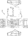
- FIG. 1 shows an example of the appearance of the toy parts corresponding to the present embodiment.
- FIG. 1A is a perspective view showing an example of the front configuration of the toy component 100 according to the embodiment.
- the toy component 100 is configured by engaging the first member 110 and the second member 120.
- FIG. 1B is a perspective view showing an example of the configuration of the back surface of the toy component 100 according to the embodiment.
- unevenness or protrusions are arranged at predetermined intervals in the lateral direction on the front surface, but on the back surface, a flat surface in which the first member 110 and the second member 120 are continuous is formed.
- the toy component 100 can come into contact with another member on the back surface and fix its position.
- a connecting portion used for connecting to another member is arranged at the bottom of the toy component 100.
- the size of the toy component 100 can be, for example, about 13.5 mm in length, about 9.5 mm in width, and about 6.3 mm in height. It was
- FIG. 2 shows a six-view view of the toy component 100.
- the protrusions having the same width are arranged in the horizontal direction.
- the lower end of each protrusion is in the same position, but the upper end is at a position where the ends of the protrusions at the left and right ends are lower than the ends of the other protrusions.
- the rest of the upper end is lower at the end of the protrusion belonging to the first member 110 than at the end of the protrusion belonging to the second member 120.
- the protrusion on the outside is higher than the protrusion on the inside.
- the ends of the three protrusions belonging to the second member 120 are at the same height. It was
- the first member 110 and the second member 120 are engaged with each other via a stepped or uneven engaging portion. Further, the first member 110 is positioned and engaged so as to be sandwiched between the protrusions at both ends of the protrusions of the second member 120. It was
- the maximum widths of the protrusions of the first member 110 and the second member 120 in the depth direction are different from each other.
- the maximum width of the protrusion of the second member 120 in the depth direction is smaller than the maximum width of the protrusion of the first member 110 in the depth direction.
- the maximum width of the protrusions at both ends in the depth direction is the depth direction of the three inner protrusions. Although it is smaller than the maximum width of, they may be equal.
- the protrusions located at both ends of the first member 110 have the largest maximum width in the depth direction.
- the two protrusions of the first member 110 sandwiched between the protrusions at both ends of the first member 110 have the same maximum width in the depth direction and are smaller than the longest width. Further, in a state where the first member 110 and the second member 120 are engaged with each other, the three protrusions inside the first member and the two protrusions inside the second member 120 are formed. It is configured so that the maximum width comes to the same position in the depth direction. It was
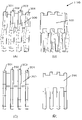
- FIG. 3A and 3B show perspective views of the front surface and the back surface of the first member 110.
- 3 (C) and 3 (D) show a front view and a rear view of the first member 110. It was
- the first member 110 has a configuration in which the main body portion 300 and the four protrusions 301 to 304 are integrated, and the protrusions 301 to 304 are partially integrated with the main body portion 300.
- the remaining portion that is not integrated with the main body portion 300 extends downward, and when engaging with the second member 120, the main body portion of the protrusions 401 to 405 described later of the second member 120. It is placed at intervals formed between the parts integrated with the 400.
- the widths of the protrusions 301 to 304 are not uniform in the depth direction, and there are a portion having a short width and a portion having a long width, and there is also a portion where the width changes. The mode of this change in width is also different between the protrusions 301 and 302, whereby a multi-layered feeling can be expressed. It was
- the main body portion 300 is formed with an engaging portion for engaging with the second member 120.
- the engaging portion is formed by alternately arranging concave portions and convex portions (steps) in the lateral direction of the first member 110, and the convex portions are formed at positions of the protrusions 301 to 304. These protrusions do not reach the tip positions of the protrusions 301 to 304 and partially cover them. It was
- the distance between the protrusions can be, for example, 1.0 mm.
- the interval may be larger or smaller depending on the size of the toy component 100.
- the first member 110 and the second member 120 are combined, it is possible to provide a space between the protrusions, and the size of the protrusions is made smaller than in the case where the protrusions are continuously formed. be able to. Therefore, the density of the protrusions can be increased as compared with the case of being composed of a single member.
- the protrusion may be tapered so as to become thinner toward the front, and in that case, for example, the lateral width of the most tip position can be 0.5 mm. It was
- FIG. 4 (A) and 4 (B) show front and back perspective views of the second member 120.
- 4 (C) and 4 (D) show a front view and a rear view of the second member 120. It was
- the second member 120 has a configuration in which the main body 400 and the five protrusions 401 to 405 are integrated, and the protrusions 401 to 405 are partially integrated with the main body 400, and the main body 400 is integrated.
- the rest which is not integrated with, extends upward in the figure.
- a connecting portion 406 for connecting to another member is arranged on the lower side of the second member 120.
- the protrusions 402 to 404 are arranged at intervals formed between the portions of the first member 110 that are integrated with the main body 300 of the protrusions 301 to 304.
- the protrusions 401 and 405 sandwich the first member 110.
- the protrusions 401 to 405 each have a non-uniform width in the depth direction, and have a short width portion and a long width portion, and also have a portion in which the width changes.
- the mode of this change in width is also different between the protrusions 401 and 402, and also different from the protrusions 301 to 304 of the first member 110. This makes it possible to express a multi-layered feeling. It was
- an engaging portion for engaging with the first member 110 is formed on the main body portion 400.
- the engaging portion is formed by alternately arranging concave portions and convex portions (steps) in the lateral direction of the second member 120, and the convex portions are formed at positions of the protrusions 401 to 405.
- the convex portion extends to the tip positions of the protrusions 401 and 405, while the protrusions 402 to 404 do not reach the tip positions and only partially cover the protrusions 402 to 404. It was
- the first member 110 and the second member 120 are engaged with each other so that the engaging portion formed on the main body portion 300 and the engaging portion formed on the main body portion 400 are engaged with each other. do.
- the distance between the protrusions can be 1.0 mm. The interval may be larger or smaller depending on the size of the toy component 100.
- the protrusion may be tapered so as to become thinner toward the front, and in that case, for example, the lateral width of the most tip position can be 0.5 mm. It was
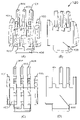
- FIG. 5 is a diagram showing cross sections of AA', BB', and CC'shown in the rear perspective view of the toy part 100 of FIG. 1B. Further, in each figure, the boundary between the main body portions 300 and 400 and each protrusion portion is shown by a alternate long and short dash line.
- FIG. 5A is a cross-sectional view taken along the line AA', in which the protrusions 402, 403, and 404 of the second member are arranged between the protrusions 301 and 304 of the first member 110, and the protrusions 401. And 405 show that the first member 110 is sandwiched. Further, in FIG.
- the cross section of the portion where the main body portion 300 and the protrusions 301 to 304 are integrated is shown in the first member 110, while the second member 120 is shown.
- the protrusions 401 and 405 are integrated with the main body 400, while the protrusions 402 to 404 are independent of the main body. It was
- FIG. 5B is a cross-sectional view taken along the line BB', showing that the protrusions 301 to 304 of the first member 110 and the protrusions 401 to 405 of the second member are alternately arranged. .. Further, since FIG. 5B shows a cross section of the engaging portion, the first member 110 shows a cross section of the convex portion of the engaging portion integrated with the protrusions 301 to 304. On the other hand, for the second member 120, the cross section of the convex portion of the engaging portion integrated with the protruding portions 401 to 405 is shown. It was
- FIG. 5C is a cross-sectional view taken along the line CC', showing how the protrusions 301 to 304 of the first member 110 are arranged between the protrusions 401 to 405 of the second member. .. Further, in FIG. 5C, the first member 110 shows a cross section of a portion where the protrusions 301 to 304 are independent of the main body 300, while the second member 120 has a protrusion. The cross section of the portion where the portions 401 to 405 are integrated with the main body portion 400 is shown.
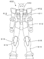
- FIG. 6 shows an example of the appearance of a model toy to which the toy component 100 corresponding to the present embodiment can be applied.
- FIG. 6 is a schematic view showing the model toy 600 according to the embodiment.
- the model toy 600 has model parts of a head portion 610, a body portion 611, an arm portion 612, a waist portion 613, and a leg portion 614, and these are combined to form a doll toy.
- At least a portion of the individual sites 610 to 614 is rotatably (or rocked) supported with respect to adjacent sites.
- the head portion 610 is rotatably supported with respect to the body portion 611
- the arm portion 612 is rotatably supported with respect to the body portion 611.
- joint structures are provided in each portion of the model toy 600, and the user (for example, the owner of the model toy 600) can put the model toy 600 in a desired posture. It was
- a cover 615 is attached to the knee joint of the leg 114, and the toy component 100 corresponding to the above-described embodiment can be arranged on the back side of the cover 615.
- the cover 615 is attached to the lower leg portion of the leg portion 114.
- the back side of the cover 615 cannot be visually recognized because the tip of the cover 615 is covered by the thigh.
- the tip portion of the cover 615 is not covered by the thigh portion, so that the toy component 100 on the back side of the cover 615 becomes visible. It was
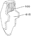
- FIG. 7 is a diagram showing an example of the configuration on the back side of the cover 615.
- the toy component 100 described in the above embodiment is arranged on the back side of the cover 615, and the toy component 100 can be visually recognized from above by bending the knee joint of the model toy 600. It was
- the present embodiment it is possible to provide a toy part having shiitake details that can be easily completed by combining a plurality of members.
- the parts can be used, for example, to fill the gaps between the parts of the model toy to create a density gap, or to be used as a component such as a heat exhaust port such as the back of the knee, so that the details of the model toy can be made more precise. Can be expressed. It was
Landscapes
- Toys (AREA)
Applications Claiming Priority (2)
| Application Number | Priority Date | Filing Date | Title |
|---|---|---|---|
| JP2020166089A JP7083381B2 (ja) | 2020-09-30 | 2020-09-30 | 玩具部品、及び、模型玩具 |
| JP2020-166089 | 2020-09-30 |
Publications (1)
| Publication Number | Publication Date |
|---|---|
| WO2022070705A1 true WO2022070705A1 (ja) | 2022-04-07 |
Family
ID=78842085
Family Applications (1)
| Application Number | Title | Priority Date | Filing Date |
|---|---|---|---|
| PCT/JP2021/031485 Ceased WO2022070705A1 (ja) | 2020-09-30 | 2021-08-27 | 玩具部品、及び、模型玩具 |
Country Status (3)
| Country | Link |
|---|---|
| JP (3) | JP7083381B2 (enExample) |
| CN (2) | CN113769416B (enExample) |
| WO (1) | WO2022070705A1 (enExample) |
Citations (5)
| Publication number | Priority date | Publication date | Assignee | Title |
|---|---|---|---|---|
| JPH0520790U (ja) * | 1991-04-05 | 1993-03-19 | 株式会社大月産業 | 雛飾り具 |
| US5593337A (en) * | 1996-01-11 | 1997-01-14 | Lapointe; Brian | Flexible toy piece set for assembly into polyhedral shapes |
| JP4299250B2 (ja) * | 2003-01-20 | 2009-07-22 | 有限会社アキ工作社 | 型板組合せの造形構造 |
| JP2015036069A (ja) * | 2013-08-13 | 2015-02-23 | 光昭 塩路 | 組立玩具 |
| US20160346707A1 (en) * | 2015-06-01 | 2016-12-01 | Mei-Tsu Lin | Dovetailed building block |
Family Cites Families (6)
| Publication number | Priority date | Publication date | Assignee | Title |
|---|---|---|---|---|
| JP3567267B2 (ja) | 2000-03-27 | 2004-09-22 | 聖二郎 内藤 | ブロック玩具 |
| DE60333947D1 (de) * | 2002-11-12 | 2010-10-07 | Mattel Inc | Reibverbindung für spielzeuge |
| BR102012018019A2 (pt) * | 2011-07-20 | 2014-05-13 | Mattel Inc | Figura de brinquedo, segmento de membro de armação para uma figura de brinquedo, membro para uma figura de brinquedo, e, método de fabricação de uma figura de brinquedo |
| GB201303315D0 (en) * | 2013-02-25 | 2013-04-10 | Morphun Res Ltd | Constructional toy |
| US9017134B1 (en) * | 2013-07-01 | 2015-04-28 | Reinar Carl Christian | Assembly kit for creating three-dimensional formations, especially toy structures from prefabricated modular building blocks |
| KR101924453B1 (ko) * | 2017-01-19 | 2018-12-03 | 에프디엠(주) | 완구용 조립 블록 |
-
2020
- 2020-09-30 JP JP2020166089A patent/JP7083381B2/ja active Active
-
2021
- 2021-08-27 WO PCT/JP2021/031485 patent/WO2022070705A1/ja not_active Ceased
- 2021-09-09 CN CN202111055027.7A patent/CN113769416B/zh active Active
- 2021-09-09 CN CN202310568904.3A patent/CN116549981A/zh active Pending
-
2022
- 2022-05-27 JP JP2022087086A patent/JP7656570B2/ja active Active
-
2025
- 2025-03-24 JP JP2025049037A patent/JP2025094185A/ja active Pending
Patent Citations (5)
| Publication number | Priority date | Publication date | Assignee | Title |
|---|---|---|---|---|
| JPH0520790U (ja) * | 1991-04-05 | 1993-03-19 | 株式会社大月産業 | 雛飾り具 |
| US5593337A (en) * | 1996-01-11 | 1997-01-14 | Lapointe; Brian | Flexible toy piece set for assembly into polyhedral shapes |
| JP4299250B2 (ja) * | 2003-01-20 | 2009-07-22 | 有限会社アキ工作社 | 型板組合せの造形構造 |
| JP2015036069A (ja) * | 2013-08-13 | 2015-02-23 | 光昭 塩路 | 組立玩具 |
| US20160346707A1 (en) * | 2015-06-01 | 2016-12-01 | Mei-Tsu Lin | Dovetailed building block |
Non-Patent Citations (1)
| Title |
|---|
| ANONYMOUS: "Shiitake detail added [HG Sinanju Stein Narrative Ver.] 07 ", 4 January 2019 (2019-01-04), XP055920454, Retrieved from the Internet <URL:https://blog.janjan.net/2019/01/04/hg-sinanju-stein-narrative-ver-07/> * |
Also Published As
| Publication number | Publication date |
|---|---|
| JP2022105751A (ja) | 2022-07-14 |
| JP7656570B2 (ja) | 2025-04-03 |
| JP2022057699A (ja) | 2022-04-11 |
| CN116549981A (zh) | 2023-08-08 |
| CN113769416B (zh) | 2023-05-23 |
| JP2025094185A (ja) | 2025-06-24 |
| JP7083381B2 (ja) | 2022-06-10 |
| CN113769416A (zh) | 2021-12-10 |
Similar Documents
| Publication | Publication Date | Title |
|---|---|---|
| USD965082S1 (en) | Treadmill | |
| USD924424S1 (en) | Massage gun | |
| USD981414S1 (en) | Stylus | |
| USD970505S1 (en) | Stylus | |
| USD981413S1 (en) | Stylus | |
| USD952061S1 (en) | Assembling toy | |
| USD954842S1 (en) | Game board | |
| USD947144S1 (en) | Vibration element for a haptic actuator | |
| USD1041916S1 (en) | Scalp cleaning massage brush | |
| USD1026338S1 (en) | Playpen for animal | |
| USD1013440S1 (en) | Pizza oven | |
| USD1005042S1 (en) | Pizza oven cover | |
| JP7083381B2 (ja) | 玩具部品、及び、模型玩具 | |
| USD1022325S1 (en) | Guide comb | |
| CN112078504A (zh) | 具有线迹线的车辆内部材料和在其上实现线迹线的方法 | |
| USD1026137S1 (en) | Pilates bar | |
| USD1014309S1 (en) | Watch band | |
| USD1011673S1 (en) | Ironing board | |
| USD1058723S1 (en) | Wrist weight | |
| USD1089429S1 (en) | Toy bubble machine | |
| USD1073974S1 (en) | Eco case | |
| USD1030923S1 (en) | Yoga mat | |
| USD1061490S1 (en) | Wide area network (WAN) apparatus | |
| USD983466S1 (en) | Cat wand toy | |
| JP3208175U (ja) | ジョイントマット |
Legal Events
| Date | Code | Title | Description |
|---|---|---|---|
| 121 | Ep: the epo has been informed by wipo that ep was designated in this application |
Ref document number: 21875008 Country of ref document: EP Kind code of ref document: A1 |
|
| NENP | Non-entry into the national phase |
Ref country code: DE |
|
| 122 | Ep: pct application non-entry in european phase |
Ref document number: 21875008 Country of ref document: EP Kind code of ref document: A1 |