WO2022070381A1 - Certificate determination device, certificate determination method, and recording medium - Google Patents
Certificate determination device, certificate determination method, and recording medium Download PDFInfo
- Publication number
- WO2022070381A1 WO2022070381A1 PCT/JP2020/037414 JP2020037414W WO2022070381A1 WO 2022070381 A1 WO2022070381 A1 WO 2022070381A1 JP 2020037414 W JP2020037414 W JP 2020037414W WO 2022070381 A1 WO2022070381 A1 WO 2022070381A1
- Authority
- WO
- WIPO (PCT)
- Prior art keywords
- shadow
- image
- certificate
- identification card
- reflected
- Prior art date
Links
- 238000000034 method Methods 0.000 title claims description 26
- 238000004364 calculation method Methods 0.000 claims description 68
- 230000008859 change Effects 0.000 claims description 57
- 238000005286 illumination Methods 0.000 claims description 20
- 238000004590 computer program Methods 0.000 claims description 10
- 230000008569 process Effects 0.000 claims description 8
- 230000035945 sensitivity Effects 0.000 claims description 3
- 238000004891 communication Methods 0.000 description 18
- 238000010191 image analysis Methods 0.000 description 16
- 238000001514 detection method Methods 0.000 description 14
- 238000010586 diagram Methods 0.000 description 9
- 230000004048 modification Effects 0.000 description 8
- 238000012986 modification Methods 0.000 description 8
- 230000003287 optical effect Effects 0.000 description 7
- 230000000694 effects Effects 0.000 description 6
- 238000003384 imaging method Methods 0.000 description 5
- 238000004088 simulation Methods 0.000 description 4
- 238000013461 design Methods 0.000 description 3
- 238000012545 processing Methods 0.000 description 3
- 230000006870 function Effects 0.000 description 1
- 230000036541 health Effects 0.000 description 1
- 239000007787 solid Substances 0.000 description 1
Images


Classifications
-
- G—PHYSICS
- G06—COMPUTING; CALCULATING OR COUNTING
- G06T—IMAGE DATA PROCESSING OR GENERATION, IN GENERAL
- G06T7/00—Image analysis
- G06T7/0002—Inspection of images, e.g. flaw detection
-
- G—PHYSICS
- G06—COMPUTING; CALCULATING OR COUNTING
- G06V—IMAGE OR VIDEO RECOGNITION OR UNDERSTANDING
- G06V30/00—Character recognition; Recognising digital ink; Document-oriented image-based pattern recognition
- G06V30/10—Character recognition
- G06V30/18—Extraction of features or characteristics of the image
- G06V30/18124—Extraction of features or characteristics of the image related to illumination properties, e.g. according to a reflectance or lighting model
-
- G—PHYSICS
- G06—COMPUTING; CALCULATING OR COUNTING
- G06T—IMAGE DATA PROCESSING OR GENERATION, IN GENERAL
- G06T7/00—Image analysis
- G06T7/90—Determination of colour characteristics
-
- G—PHYSICS
- G06—COMPUTING; CALCULATING OR COUNTING
- G06V—IMAGE OR VIDEO RECOGNITION OR UNDERSTANDING
- G06V10/00—Arrangements for image or video recognition or understanding
- G06V10/40—Extraction of image or video features
- G06V10/56—Extraction of image or video features relating to colour
-
- G—PHYSICS
- G07—CHECKING-DEVICES
- G07D—HANDLING OF COINS OR VALUABLE PAPERS, e.g. TESTING, SORTING BY DENOMINATIONS, COUNTING, DISPENSING, CHANGING OR DEPOSITING
- G07D7/00—Testing specially adapted to determine the identity or genuineness of valuable papers or for segregating those which are unacceptable, e.g. banknotes that are alien to a currency
- G07D7/06—Testing specially adapted to determine the identity or genuineness of valuable papers or for segregating those which are unacceptable, e.g. banknotes that are alien to a currency using wave or particle radiation
- G07D7/12—Visible light, infrared or ultraviolet radiation
-
- G—PHYSICS
- G07—CHECKING-DEVICES
- G07D—HANDLING OF COINS OR VALUABLE PAPERS, e.g. TESTING, SORTING BY DENOMINATIONS, COUNTING, DISPENSING, CHANGING OR DEPOSITING
- G07D7/00—Testing specially adapted to determine the identity or genuineness of valuable papers or for segregating those which are unacceptable, e.g. banknotes that are alien to a currency
- G07D7/16—Testing the dimensions
- G07D7/164—Thickness
-
- G—PHYSICS
- G07—CHECKING-DEVICES
- G07D—HANDLING OF COINS OR VALUABLE PAPERS, e.g. TESTING, SORTING BY DENOMINATIONS, COUNTING, DISPENSING, CHANGING OR DEPOSITING
- G07D7/00—Testing specially adapted to determine the identity or genuineness of valuable papers or for segregating those which are unacceptable, e.g. banknotes that are alien to a currency
- G07D7/20—Testing patterns thereon
- G07D7/2016—Testing patterns thereon using feature extraction, e.g. segmentation, edge detection or Hough-transformation
-
- G—PHYSICS
- G06—COMPUTING; CALCULATING OR COUNTING
- G06T—IMAGE DATA PROCESSING OR GENERATION, IN GENERAL
- G06T2207/00—Indexing scheme for image analysis or image enhancement
- G06T2207/30—Subject of image; Context of image processing
- G06T2207/30176—Document
Definitions
- This disclosure relates to a technical field of a certificate determination device, a certificate determination method, and a recording medium capable of determining whether or not an identification card reflected in an image is genuine.
- a method of proving the user's identity by using an image obtained by imaging the user's identification card has been adopted in various fields.
- the contractor is requested to send an image of the contractor's identification card, and the contractor uses the identification card reflected in the sent image.
- the method of proving the identity of the person is adopted.
- the image used to prove the user's identity is an image generated by imaging a real ID card, or a fake ID card (eg, a document with a copy of the ID card). It is desirable to appropriately determine whether the image is generated by imaging.
- One aspect of the certificate determination device of the present disclosure is a generation means for generating shadow information regarding a shadow of the identification card reflected in the image based on an image in which the identification card is reflected, and the shadow information. Based on this, it is provided with a determination means for determining whether or not the identification card reflected in the image is genuine.
- One aspect of the certificate determination method of the present disclosure is a generation step of generating shadow information regarding a shadow of the identification card reflected in the image based on an image in which the identification card is reflected, and the shadow information. Based on this, it includes a determination step of determining whether or not the identification card reflected in the image is genuine.
- One aspect of the recording medium of the present disclosure is a recording medium in which a computer program for causing a computer to execute a certificate determination method is recorded, and the certificate determination method is based on an image in which an identification card is reflected. Based on the generation step of generating shadow information regarding the shadow of the identification card reflected in the image and the shadow information, it is determined whether or not the identification card reflected in the image is genuine. Includes a determination step.
- FIG. 1 is a block diagram showing an overall configuration of the certificate determination system of the first embodiment.
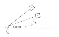
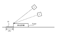
- FIG. 2 is a side view showing an example of a light source and a camera that capture an identification card.
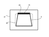
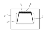
- FIG. 3 is a plan view showing an example of a certificate image.
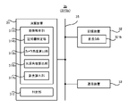
- FIG. 4 is a block diagram showing the configuration of the determination server of the first embodiment.
- FIG. 5 is a flowchart showing the flow of the certificate determination operation performed by the determination server of the first embodiment.
- FIG. 6 is a side view showing a fake ID card illuminated by a light source.
- FIG. 7 is a side view showing a genuine ID card illuminated by a light source.
- FIG. 8 is a block diagram showing the configuration of the determination server of the second embodiment.
- FIG. 1 is a block diagram showing an overall configuration of the certificate determination system of the first embodiment.
- FIG. 2 is a side view showing an example of a light source and a camera that capture an identification card.
- FIG. 3 is a plan view showing an
- FIG. 9 is a side view showing a camera angle and a light source angle.
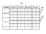
- FIG. 10 is a data structure diagram showing an example of the data structure of the shadow length DB.
- FIG. 11 is a flowchart showing the flow of the certificate determination operation performed by the determination server of the second embodiment.
- FIG. 12 is a plan view showing a certificate image generated under a situation where the camera angle is relatively large.
- FIG. 13 is a plan view showing a certificate image generated under a situation where the camera angle is relatively small.
- FIG. 14 is a side view showing the length of the shadow of a real ID card.
- FIG. 15 is a side view showing the length of the shadow of the fake ID card.
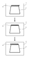
- FIG. 16 is a plan view showing how the direction in which the shadow extends changes.
- FIG. 17 is a data structure diagram showing an example of the data structure of the shadow length DB in the first modification.
- FIG. 18 is a block diagram showing a configuration of the determination server according to the third embodiment.
- Certificate determination system SYS of the first embodiment First, the certificate determination system SYS of the first embodiment will be described. In the following description, the certificate determination system SYS of the first embodiment will be referred to as "certificate determination system SYSA”.
- FIG. 1 is a block diagram showing a configuration of the certificate determination system SYSA of the first embodiment.
- the certificate determination system SYSa includes a light source 1, a camera 2 which is a specific example of an “imaging device”, and a determination server 3 which is a specific example of a “certificate determination device”. .. At least one of the light source 1 and the camera 2 can communicate with the determination server 3 via the communication network (or an arbitrary control line) 4.
- the communication network 4 may include a wired communication network or may include a wireless communication network.
- the light source 1 and the camera 2 are used to image the user's identification card 5 (see FIG. 2).
- the identification card 5 may mean a physical document that can be used to illuminate the user's identity (in other words, identity or identity).
- the identification card 5 at least one of a driver's license, a passport (passport), a health insurance card, an individual number card and an ID card can be mentioned.
- FIG. 2 shows an example of the light source 1 and the camera 2 that capture the identification card 5.
- the light source 1 illuminates the identification card 5 with the illumination light IL.
- the camera 2 takes an image of the identification card 5 illuminated by the illumination light IL from the light source 1.
- the camera 2 generates an image (hereinafter, appropriately referred to as “certificate image 21”) in which the identification card 5 is reflected.
- the camera 2 transmits the generated certificate image 21 to the determination server 3 via the communication network 4.
- the positional relationship between the light source 1 and the camera 2 is fixed. That is, it is preferable that the positional relationship between the light source 1 and the camera 2 does not change.
- the positional relationship between the light source 1 and the camera 2 is preferably information known to the determination server 3.
- a single device may include the light source 1 and the camera 2. That is, the light source and the camera included in the single device may be used as the light source 1 and the camera 2.
- the light source and camera provided in the smartphone or tablet terminal may be used as the light source 1 and the camera 2.
- the positional relationship between the light source 1 and the camera 2 does not have to be fixed. That is, the positional relationship between the light source 1 and the camera 2 may change. Even in this case, it is preferable that the positional relationship between the light source 1 and the camera 2 is information known to the determination server 3. That is, when the positional relationship between the light source 1 and the camera 2 changes, it is preferable that the determination server 3 can specify the positional relationship between the light source 1 and the camera 2 after the change.
- the determination server 3 performs a certificate determination operation for determining whether or not the identification card 5 reflected in the certificate image 21 is genuine based on the certificate image 21. Specifically, the determination server 3 generates the certificate image 21 by imaging the real identification card 5 (hereinafter, appropriately referred to as "identification card 5_real") based on the certificate image 21. It is determined whether the image is a fake image or an image generated by photographing a fake ID card 5 (hereinafter, appropriately referred to as "identification card 5_fake").
- the genuine ID card 5_real in the first embodiment may mean the ID card 5 itself (in other words, the original ID card 5).
- the fake ID card 5_fake in the first embodiment may mean something that imitates the ID card 5 although it is not the ID card 5 itself.
- the ID card 5_fake there is at least one of a display on which a document on which the ID card 5_real is copied and an image in which the ID card 5_real is reflected are displayed.
- the determination server 3 generates shadow information regarding the shadow 51 of the identification card 5 reflected in the certificate image 21, and reflects the shadow information in the certificate image 21 based on the generated shadow information. It is determined whether or not the existing identification card 5 is genuine. Specifically, as shown in FIG. 2 described above, when the light source 1 illuminates the ID card 5_real with the illumination light IL, a shadow 51 of the ID card 5_real is usually generated. As a result, as shown in FIG. 3, which is an example of the certificate image 21, the shadow 51 of the identification card 5_real is also reflected in the certificate image 21 in which the identification card 5_real is reflected. On the other hand, the ID card 5_fake generally has a different thickness than the ID card 5_real.
- the determination server 3 can determine whether or not the identification card 5 reflected in the certificate image 21 is genuine based on the shadow information.
- FIG. 4 shows an example of the configuration of the determination server 3 that performs such a certificate determination operation.
- the determination server 3 includes an arithmetic unit 31, a storage device 32, and a communication device 33.
- the arithmetic unit 31, the storage device 32, and the communication device 33 are connected via the data bus 34.
- the arithmetic unit 31 includes, for example, a CPU (Central Processing Unit).
- the arithmetic unit 31 reads a computer program.
- the arithmetic unit 31 may read the computer program stored in the storage device 32.
- the arithmetic unit 31 may read a computer program stored in a recording medium that is readable by a computer and is not temporary by using a recording medium reading device (not shown).
- the arithmetic unit 31 may acquire a computer program from a device (not shown) arranged outside the determination server 3 via the communication device 33 (that is, it may be downloaded or read).
- the arithmetic unit 31 executes the read computer program.
- a logical functional block for executing an operation to be performed by the determination server 3 (for example, the above-mentioned certificate determination operation) is realized in the arithmetic unit 31. That is, the arithmetic unit 31 can function as a controller for realizing a logical functional block for executing the operation to be performed by the determination server 3.
- FIG. 4 shows an example of a logical functional block realized in the arithmetic unit 31 to execute the certificate determination operation.
- an image analysis unit 311 and a determination unit 312, which is a specific example of the "determination means” are realized in the arithmetic unit 31.
- the shadow detection unit 313, which is a specific example of the "generation means” is realized as a logical functional block. The operations of the image analysis unit 311 and the determination unit 312 will be described in detail later with reference to FIG. 5 and the like.
- the storage device 32 can store desired data.
- the storage device 32 may temporarily store the computer program executed by the arithmetic unit 31.
- the storage device 32 may temporarily store data temporarily used by the arithmetic unit 31 while the arithmetic unit 31 is executing a computer program.
- the storage device 32 may store data stored by the determination server 3 for a long period of time.
- the storage device 32 may include at least one of a RAM (Random Access Memory), a ROM (Read Only Memory), a hard disk device, a magneto-optical disk device, an SSD (Solid State Drive), and a disk array device. good.
- the communication device 33 can communicate with at least one of the light source 1 and the camera 2 via the communication network 4.
- the communication device 33 may receive the certificate image 21 transmitted from the camera 2 via the communication network 4.
- FIG. 5 is a flowchart showing the flow of the certificate determination operation performed by the determination server 3 of the first embodiment.
- the image analysis unit 311 uses the communication device 33 to acquire the certificate image 21 transmitted from the camera 2 via the communication network 4 (step S11).
- the shadow detection unit 313 of the image analysis unit 311 detects the shadow 51 of the identification card 5 reflected in the certificate image 21 based on the certificate image 21 acquired in step S11 (step S12). Specifically, the shadow detection unit 313 analyzes the certificate image 21 to capture an image area (hereinafter referred to as “certificate area 22”) in which the identification card 5 is reflected in the certificate image 21. 3) is specified. After that, the shadow detection unit 313 analyzes the certificate image 21 to extend outward from the certificate area 22 and the shadow 51 of the identification card 5 is reflected in the image area (hereinafter, “shadow area”). It is determined whether or not there is (see FIG. 3) referred to as “23”.
- the shadow detection unit 313 determines that the shadow 51 of the identification card 5 is reflected in the certificate image 21.
- the shadow detection unit 313 determines that the shadow 51 of the identification card 5 is not reflected in the certificate image 21.
- the detection result of the shadow 51 by the shadow detection unit 313 in step S12 is output from the shadow detection unit 313 to the determination unit 312 as shadow information. That is, in the first embodiment, the shadow information including the information regarding the presence / absence of the shadow 51 in the certificate image 21 is output from the shadow detection unit 313 to the determination unit 312.
- the determination unit 312 determines whether or not the identification card 5 reflected in the certificate image 21 is genuine based on the shadow information (step S13). Specifically, as described above, the thickness of the ID card 5_fake is relatively likely to be thinner (especially much thinner) than the thickness of the ID card 5_real. Therefore, as shown in FIG. 6, which is a side view showing the identification card 5_fake illuminated by the light source 1, when the light source 1 illuminates the identification card 5_fake with the illumination light IL, the identification card There is a high possibility that the shadow 51 of 5_fake is hardly generated.
- FIG. 7 which is a side view showing the identification card 5_real illuminated by the light source 1
- the identification card 5_real has a certain thickness.
- the shadow 51 of the identification card 5_real is reflected in the certificate image 21 in which the identification card 5_real is reflected.
- the determination unit 312 determines that the identification card 5 reflected in the certificate image 21 is a fake when the shadow 51 is not reflected in the certificate image 21. May be good. That is, the determination unit 312 may determine that the identification card 5_fake is reflected in the certificate image 21. On the other hand, the determination unit 312 determines that the identification card 5 reflected in the certificate image 21 is genuine when the shadow 51 is reflected in the certificate image 21 based on the shadow information. You may. That is, the determination unit 312 may determine that the identification card 5_real is reflected in the certificate image 21.
- the certificate judgment system SYSA (particularly, judgment server 3) of the first embodiment has an identification card reflected in the certificate image 21. Based on the presence or absence of the shadow 51 of 5, it can be determined whether or not the identification card 5 reflected in the certificate image 21 is genuine. Therefore, as compared with the case where a person visually confirms the certificate image 21 to determine whether or not the identification card 5 reflected in the certificate image 21 is genuine, the certificate determination system SYSSa (In particular, the determination server 3) can determine whether or not the identification card 5 reflected in the certificate image 21 is genuine at a relatively low cost.
- Certificate determination system SYS of the second embodiment (2) Certificate determination system SYS of the second embodiment Subsequently, the certificate determination system SYS of the second embodiment will be described. In the following description, the certificate determination system SYS of the second embodiment will be referred to as "certificate determination system SYSb".
- the certificate judgment system SYSb of the second embodiment replaces the judgment server 3 as compared with the certificate judgment system SYSa of the first embodiment. It differs in that it includes a determination server 3b. Other features of the certificate determination system SYSb may be the same as other features of the certificate determination system SYSa.
- the judgment server 3b Similar to the judgment server 3, the judgment server 3b generates shadow information regarding the shadow 51 of the identification card 5 reflected in the certificate image 21, and reflects the shadow information on the certificate image 21 based on the generated shadow information. Performs a certificate determination operation for determining whether or not the existing identification card 5 is genuine. However, the determination server 3b generates the shadow information including the information regarding the presence / absence of the shadow 51 of the identification card 5 in that the determination server 3b generates the shadow information including the information regarding the length L of the shadow 51 of the identification card 5. Different from server 3. Other features of the determination server 3b may be the same as other features of the determination server 3. Therefore, in the following, the determination server 3b of the second embodiment will be described with reference to FIG. 8, focusing on the differences between the determination server 3b and the determination server 3.
- FIG. 8 is a block diagram showing the configuration of the determination server 3b of the second embodiment.
- the determination server 3b is different from the determination server 3 in that the image analysis unit 311b is realized in the arithmetic unit 31 instead of the image analysis unit 311. Further, the determination server 3b is different from the determination server 3 in that the storage device 32 stores the shadow length DB321b, which is a specific example of the “estimated length data”. Other configurations of the determination server 3b may be the same as other configurations of the determination server 3.
- the image analysis unit 311b replaces the shadow detection unit 313 with a certificate identification unit 314b, a camera angle calculation unit 315b which is a specific example of the "calculation means", and a "calculation means”.
- the light source angle calculation unit 316b which is a specific example of the above
- the shadow length calculation unit 317b which is a specific example of the “generation means”.
- the certificate specifying unit 314b identifies the type of the identification card 5 reflected in the certificate image 21 based on the certificate image 21.
- the camera angle calculation unit 315b calculates the angle of the camera 2 with respect to the identification card 5 (hereinafter referred to as “camera angle ⁇ c”) based on the certificate image 21.
- the light source angle calculation unit 316b calculates the angle of the light source 1 with respect to the identification card 5 (hereinafter referred to as “light source angle ⁇ o”) based on the certificate image 21.
- the shadow length calculation unit 317b calculates the length L of the shadow 51 of the identification card 5 reflected in the certificate image 21 based on the certificate image 21.
- the determination unit 312 is a certificate image based on the camera angle ⁇ c calculated by the camera angle calculation unit 315b, the light source angle ⁇ o calculated by the light source angle calculation unit 316b, and the length L of the shadow 51 calculated by the shadow length calculation unit 317b. It is determined whether or not the identification card 5 reflected in the 21 is genuine.
- the camera angle ⁇ c is a parameter (in other words, an index) that represents the relative positional relationship between the camera 2 and the ID card 5.
- An example of the camera angle ⁇ c is shown in FIG.
- the camera angle ⁇ c may indicate, for example, the angle formed by the camera axis AC extending from the camera 2 and the surface of the ID card 5.
- the camera angle ⁇ c is, for example, the angle formed in the vertical direction between the camera axis AC and the axis along the surface of the ID card 5 (for example, the axis along either the short side or the long side of the ID card 5). (See FIG.
- the camera axis AC may be an axis extending from the camera 2 toward a predetermined position of the ID card 5 (in the example shown in FIG. 9, the upper end of the ID card 5).
- the camera axis AC may be an axis along the optical axis of the optical system (for example, a lens) included in the camera 2.
- the light source angle ⁇ o is a parameter (in other words, an index) that represents the relative positional relationship between the light source 1 and the ID card 5.
- An example of the light source angle ⁇ o is shown in FIG.
- the light source angle ⁇ o may indicate, for example, the angle formed by the light source axis OC extending from the light source 1 and the surface of the ID card 5.
- the light source angle ⁇ o is, for example, the angle formed in the vertical direction between the light source axis OC and the axis along the surface of the ID card 5 (for example, the axis along either the short side or the long side of the ID card 5). (See FIG.
- the light source axis OC may be an axis extending from the light source 1 toward a predetermined position of the ID card 5 (in the example shown in FIG. 9, the upper end of the ID card 5).
- the light source axis OC may be an axis along the optical axis of the optical system (for example, a lens) included in the light source 1.
- the light source axis OC may be an axis along the traveling direction of the illumination light IL emitted from the light source 1.
- the shadow length DB321b is a database referred to by the determination unit 312 in order to determine whether or not the identification card 5 reflected in the certificate image 21 is genuine. Specifically, the shadow length DB321b is presumed to be reflected in the certificate image 21 from the camera angle ⁇ c calculated by the camera angle calculation unit 315b and the light source angle ⁇ o calculated by the light source angle calculation unit 316b. It is used to estimate the length L of the shadow 51 of the book 5. Therefore, the shadow length DB321b is a database showing the relationship between the camera angle ⁇ c and the light source angle ⁇ o and the length L of the shadow 51. An example of the data structure of the shadow length DB321b is shown in FIG. As shown in FIG.
- the shadow length DB321b includes a plurality of record data 322b.
- the camera 2 captured the real identification card 5_real illuminated by the light source 1 under the condition that the camera angle ⁇ c is a predetermined first angle and the light source angle ⁇ o is a predetermined second angle.
- the length L of the shadow 51 of the identification certificate 5_real which is presumed to be reflected in the certificate image 21, is associated with the camera angle ⁇ c and the light source angle ⁇ o. That is, in each record data 322b, the identification card 5_real illuminated by the light source 1 arranged so that the light source angle ⁇ o becomes a predetermined second angle is arranged so that the camera angle ⁇ c becomes a predetermined second angle.
- the theoretical (in other words, design) length L of the shadow 51 of the identification card 5_real, which is presumed to be reflected in the certificate image 21, assuming that the camera 2 has taken an image, is the camera. It is associated with the angle ⁇ c and the light source angle ⁇ o.
- the shadow length DB321b is, for example, (i) an identification 5_real illuminated by the light source 1 arranged so that the light source angle ⁇ o is the angle a2, and the camera angle ⁇ c is the angle a1.
- Record data 322b indicating that the length L of the shadow 51 of the identification card 5_real, which is presumed to be reflected in the certificate image 21, is a4, assuming that the camera 2 arranged in the above manner captures the image.
- the length L of the shadow 51 of the ID card 5_real may change depending on the distance (that is, the distance) D between the light source 1 and the camera 2 in addition to the light source angle ⁇ o and the camera angle ⁇ c. .. Therefore, in each record data 322b, the camera angle ⁇ c is a predetermined first angle, the light source angle ⁇ o is a predetermined second angle, and the distance D between the light source 1 and the camera 2 is a predetermined distance.
- the length of the shadow 51 of the identification card 5_real that is presumed to be reflected in the certificate image 21 if the camera 2 takes an image of the real identification card 5_real illuminated by the light source 1 under the circumstances.
- the L may be associated with the camera angle ⁇ c, the light source angle ⁇ o, and the distance D between the light source 1 and the camera 2.
- the "distance" in the second embodiment may include at least one of a distance along the X axis, a distance along the Y axis, and a distance along the Z axis in the XYZ coordinate systems orthogonal to each other.
- the shadow length DB321b is, for example, (i) an identification 5_real illuminated by the light source 1 arranged so that the light source angle ⁇ o is the angle a2, and the camera angle ⁇ c is the angle a1.
- the length L of the shadow 51 of the identification card 5_real estimated to be reflected in the certificate image 21 is a4.
- the record data 322b indicating that there is, and (ii) the identification certificate 5_real illuminated by the light source 1 arranged so that the light source angle ⁇ o is the angle b2, the camera angle ⁇ c is the angle b1 and the distance b3 from the light source 1.
- a record indicating that the length L of the shadow 51 of the identification card 5_real, which is presumed to be reflected in the certificate image 21, is b4, assuming that the camera 2 is arranged so as to be separated from the image. Includes data 322b.
- the length L of the shadow 51 of the ID card 5_real may change depending on the thickness of the ID card 5_real in addition to the light source angle ⁇ o and the camera angle ⁇ c.
- the thickness of the ID card 5_real depends on the type of the ID card 5_real. For example, the thickness of a driver's license, which is an example of ID card 5_real, is different from the thickness of a passport, which is an example of ID card 5_real. Therefore, the shadow length DB321b may include record data 322b for each type of identification card 5_real.
- the shadow length DB321b is the length of the record data 322b indicating the length of the shadow 51 of the first type of identification card 5_real and the length of the shadow 51 of the second type of identification card 5_real different from the first type.
- the record data 322b indicating the above may be included.
- the shadow length DB321b is the record data 322b indicating the length L of the shadow 51 of the driver's license, which is an example of the identification card 5_real, and the shadow 51 of the passport, which is an example of the identification card 5_real. It includes record data 322b indicating a length L.
- the determination unit 312 is reflected in the certificate image 21 based on such a shadow length DB321b, a camera angle ⁇ c calculated by the camera angle calculation unit 315b, and a light source angle ⁇ o calculated by the light source angle calculation unit 316b.
- the length L of the shadow 51 of the estimated identification card 5 (that is, the estimated value of the length L of the shadow 51) is estimated. That is, the determination unit 312 assumes that the real identification card 5_real is reflected in the certificate image 21, and the length L of the shadow 51 reflected in the certificate image 21 (that is, the length L of the shadow 51). Estimated value).
- the determination unit 312 determines the length L of the shadow 51 estimated by the determination unit 312 (that is, the estimated value of the length L of the shadow 51) and the length L of the shadow 51 calculated by the shadow length calculation unit 317b (that is, that is). , The calculated value of the length L of the shadow 51), and it is determined whether or not the identification card 5 reflected in the certificate image 21 is genuine.
- FIG. 11 is a flowchart showing the flow of the certificate determination operation performed by the determination server 3 of the second embodiment.
- the image analysis unit 311 uses the communication device 33 to acquire the certificate image 21 transmitted from the camera 2 via the communication network 4 (step S21).
- the certificate identification unit 314b of the image analysis unit 311 specifies the type of the identification card 5 reflected in the certificate image 21 based on the certificate image 21 acquired in step S11 (step S22). That is, the certificate specifying unit 314b analyzes the certificate image 21 to specify the type of the identification card 5 reflected in the certificate image 21 (step S22). For example, the certificate identification unit 314b identifies the type of the ID card 5 based on the characteristics of the ID card 5 (for example, at least one of size, color, and shape) reflected in the certificate image 21. You may. For example, the certificate specifying unit 314b may specify the type of the ID card 5 by performing pattern matching processing on the certificate image 21 using a template conforming to the format of the ID card 5. ..
- the certificate specifying unit 314b identifies the image area (that is, the certificate area 22) in which the identification card 5 is reflected in the certificate image 21 as in the shadow detection unit 313 of the first embodiment. You may.
- the image analysis unit 311 does not have to specify the type of the identification card 5. In this case, the image analysis unit 311 may not include the certificate identification unit 314b.
- the shadow length calculation unit 317b calculates the length L of the shadow 51 of the identification card 5 reflected in the certificate image 21 based on the certificate image 21 acquired in step S11 (step S23).
- the size of the identification card 5 is an eigenvalue depending on the type of the identification card 5. Therefore, the size of the identification card 5 can be used as a reference length when calculating the length L of the shadow 51. Therefore, first, the shadow length calculation unit 317b determines the size of the identification card 5 (for example, the length of at least one of the long side and the short side) based on the type of the identification card 5 specified by the certificate identification unit 314b. ).
- the size of the identification card 5 is equivalent to the size of the certificate area 22 in the certificate image 21.
- the shadow length calculation unit 317b detects an image region (that is, a shadow region 23) in which a shadow extending outward from the certificate region 22 is reflected, similarly to the shadow detection unit 313 described in the first embodiment. do. After that, the shadow length calculation unit 317b calculates the size of the detected shadow area 23 based on the size of the certificate area 22.
- the size of the shadow area 23 is, for example, from one end of the shadow area 23 adjacent to the certificate area 22 to the other end of the shadow area 23 away from the certificate area 22 along the traveling direction of the illumination light IL. It may be the distance to the part.
- the calculated size of the shadow region 23 is used as the length L of the shadow 51.
- the calculation result of the length L of the shadow 51 by the shadow length calculation unit 317b in step S23 is output from the shadow length calculation unit 317b to the determination unit 312 as shadow information. That is, in the second embodiment, the shadow information including the information regarding the length L of the shadow 51 in the certificate image 21 is output from the shadow length calculation unit 317b to the determination unit 312.
- the camera angle calculation unit 315b determines the angle of the camera 2 with respect to the identification card 5 (that is, the camera angle ⁇ c) based on the certificate image 21 acquired in step S11. ) Is calculated (step S24). Specifically, when the camera angle ⁇ c changes, the ratio of the lengths of the two intersecting sides (for example, the long side and the short side) of the identification card 5 reflected in the certificate image 21 changes.
- FIG. 12 shows a certificate image 21 generated under a situation where the camera angle ⁇ c formed by the camera axis AC and the surface of the ID card 5 is relatively large
- FIG. 13 shows the camera axis AC.
- the certificate image 21 generated under the condition that the camera angle ⁇ c formed by the surface of the identification card 5 is relatively small is shown.
- the smaller the camera angle ⁇ c the shorter the short side of the ID card 5 (the side extending in the left-right direction in the examples shown in FIGS. 12 and 13) of the ID card 5.
- the ratio of the sides extending in the vertical direction becomes small. Therefore, the camera angle calculation unit 315b may calculate the camera angle ⁇ c based on the ratio of the lengths of the two intersecting sides of the ID card 5.
- the camera angle ⁇ c calculated here corresponds to the camera angle ⁇ c at the time when the camera 2 captures the identification card 5.
- the camera angle ⁇ c calculated in step S24 is output from the camera angle calculation unit 315b to the determination unit 312.
- the light source angle calculation unit 316b calculates the angle of the light source 1 with respect to the identification card 5 (that is, the light source angle ⁇ o) based on the camera angle ⁇ c specified in step S24 (step S25). Specifically, when the positional relationship between the light source 1 and the camera 2 is fixed as described above, when the camera angle ⁇ c is determined, the light source angle ⁇ o is also uniquely determined. Alternatively, even if the positional relationship between the light source 1 and the camera 2 is not fixed, the camera angle ⁇ c is determined when the positional relationship between the light source 1 and the camera 2 is known information to the determination server 3. And the light source angle ⁇ o is also uniquely determined.
- the light source angle calculation unit 316b can calculate the light source angle ⁇ o based on the camera angle ⁇ c (further, based on the positional relationship between the light source 1 and the camera 2 if necessary).
- the light source angle ⁇ o calculated here corresponds to the light source angle ⁇ o at the time when the camera 2 takes an image of the identification card 5.
- the light source angle ⁇ o calculated in step S25 is output from the light source angle calculation unit 316b to the determination unit 312.
- the determination unit 312 After that, it is estimated that the determination unit 312 will be reflected in the certificate image 21 based on the camera angle ⁇ c calculated in step S24, the light source angle ⁇ o calculated in step S25, and the shadow length DB321b.
- the length L of the shadow 51 of the identification card 5 is estimated (step S26). That is, the determination unit 312 assumes that the real identification card 5_real is reflected in the certificate image 21, and the length L of the shadow 51 reflected in the certificate image 21 (that is, the length L of the shadow 51). Estimated value).
- the determination unit 312 uses the real identification card 5_real illuminated by the light source 1 arranged at the position based on the light source angle ⁇ o calculated in step S25 based on the camera angle ⁇ c calculated in step S24.
- the theoretical (in other words, design) length of the shadow 51 of the ID card 5_real which is presumed to be reflected in the certificate image 21, assuming that the camera 2 located at the position has taken an image.
- Estimate L In order to estimate the length L of the shadow 51, for example, the determination unit 312 obtains record data 322b corresponding to the camera angle ⁇ c calculated in step S24 and the light source angle ⁇ o calculated in step S25 from the shadow length DB 321b. Extract. After that, the determination unit 312 uses the length L of the shadow 51 indicated by the extracted record data 322b as an estimated value of the length L of the shadow 51.
- the determination unit 312 specifies the distance D between the light source 1 and the camera 2.
- the record data 322b corresponding to the specified distance D may be extracted from the shadow length DB321b.
- the distance D between the light source 1 and the camera 2 is a fixed value when the positional relationship between the light source 1 and the camera 2 is fixed.
- the distance D between the light source 1 and the camera 2 is a variable value.
- the determination server 3 may specify the distance D between the light source 1 and the camera 2. can.
- the determination unit 312 is reflected on the certificate image 21 based on the calculated value of the length L of the shadow 51 calculated in step S23 and the estimated value of the length L of the shadow 51 estimated in step S26. It is determined whether or not the embedded identification card 5 is genuine (step S27). Specifically, as shown in FIG. 14, when the identification card 5 reflected in the certificate image 21 is genuine (that is, the identification card 5_real), the length L of the shadow 51 The calculated value L1 is substantially the same as the estimated value of the length L of the shadow 51 (that is, the theoretical length L). On the other hand, as shown in FIG.
- the calculated value L2 of the length L of the shadow 51 Is a value different from the estimated value of the length L of the shadow 51 (that is, the theoretical length L). This is because when the ID card 5 reflected in the certificate image 21 is not genuine, the calculated value of the length L of the shadow 51 is the shadow 51 of the ID card 5_fake whose thickness is different from that of the ID card 5_real. This is because it indicates the length L of.
- the calculated value L2 of the length L of the shadow 51 of the ID card 5_fake corresponds to the theoretical value of the length L1 of the shadow 51 of the ID card 5_real (or the length L1 of the shadow 51 of the ID card 5_real).
- Estimated value of the length L of the shadow 51 Therefore, the determination unit 312 compares the calculated value of the length L of the shadow 51 calculated in step S23 with the estimated value of the length L of the shadow 51 estimated in step S26 to obtain the certificate image 21. It is possible to determine whether or not the identification card 5 reflected in the image is genuine.
- the difference between the calculated value of the length L of the shadow 51 and the estimated value of the length L of the shadow 51 is larger than the predetermined first allowable amount (that is, the calculation of the length L of the shadow 51). If the value is significantly different from the estimated value of the length L of the shadow 51), it may be determined that the identification card 5 reflected in the certificate image 21 is not genuine.
- the difference between the calculated value of the length L of the shadow 51 and the estimated value of the length L of the shadow 51 is smaller than the predetermined second allowable amount equal to or less than the first allowable amount (that is, the shadow 51). If the calculated value of the length L of the shadow 51 does not differ significantly from or is approximately the same as the estimated value of the length L of the shadow 51), it is considered that the identification card 5 reflected in the certificate image 21 is genuine. You may judge.
- the first and second permissible amounts are the state in which the identification card 5 reflected in the certificate image 21 is genuine and the state in which the identification card 5 reflected in the certificate image 21 is not genuine. , It may be set to an appropriate value that can be distinguished from the length L of the shadow 51 of the identification card 5 reflected in the certificate image 21. Such first and second tolerances may be set experimentally or by simulation. The first allowable amount may be the same as or different from the second allowable amount.
- the certificate judgment system SYSb (particularly, judgment server 3b) of the second embodiment has an identification card reflected in the certificate image 21. Based on the length L of the shadow 51 of 5, it can be determined whether or not the identification card 5 reflected in the certificate image 21 is genuine. Therefore, the certificate determination system SYSb is compared with the case where a person visually confirms the certificate image 21 to determine whether or not the identification card 5 reflected in the certificate image 21 is genuine. (In particular, the determination server 3b) can determine whether or not the identification card 5 reflected in the certificate image 21 is genuine at a relatively low cost.
- the certificate determination system SYSb (particularly, the determination server 3b) can determine with higher accuracy whether or not the identification card 5 reflected in the certificate image 21 is genuine.
- the determination server 3b is a shadow containing information about a change in length L (typically a time-series change) of the shadow 51 of the ID card 5. Information may be generated. Specifically, the determination server 3b acquires a plurality of certificate images 21 transmitted from the camera 2. The plurality of certificate images 21 are generated by repeating the operation of the camera 2 taking an image of the identification card 5 and the operation of changing the positional relationship between the identification card 5 and at least one of the light source 1 and the camera 2. To. That is, in the first modification, the camera 2 takes an image of the identification card 5 each time the positional relationship between the identification card 5 and at least one of the light source 1 and the camera 2 is changed.
- the plurality of certificate images 21 may be a plurality of images constituting the moving image.
- the shadow length calculation unit 317b of the determination server 3b calculates the length L of the shadow 51 of the identification card 5 reflected in each of the plurality of certificate images 21.
- the shadow length calculation unit 317b can calculate the time-series change of the length L of the shadow 51.
- the calculation result of the length L of the shadow 51 by the shadow length calculation unit 317b is output from the shadow length calculation unit 317b to the determination unit 312 as shadow information.
- the camera angle calculation unit 315b calculates the camera angle ⁇ c based on each of the plurality of certificate images 21. As a result, the camera angle calculation unit 315b calculates the time-series change of the camera angle ⁇ c. Similarly, the light source angle calculation unit 316b calculates the time-series change of the light source angle ⁇ o based on the time-series change of the camera angle ⁇ c.
- the determination unit 312 presumes that the identification card 5 will be reflected in the certificate image 21 based on the time-series change of the camera angle ⁇ c, the time-series change of the light source angle ⁇ o, and the shadow length DB321b. Estimate the time-series change of the length L of the shadow 51 of. That is, the determination unit 312 changes the length L of the shadow 51 reflected on the certificate image 21 over time (that is, the shadow 51) on the assumption that the real identification card 5_real is reflected on the certificate image 21. (Estimated value of time-series change of length L) is estimated.
- the determination unit 312 uses the calculated value of the time-series change of the length L of the shadow 51 calculated by the shadow length calculation unit 317b and the estimated value of the time-series change of the length L of the shadow 51 estimated by the determination unit 312. By comparing, it is determined whether or not the identification card 5 reflected in the certificate image 21 is genuine. That is, in the first modification, the determination unit 312 has a change pattern of the length L of the shadow 51 actually reflected in the certificate image 21 (hereinafter referred to as “actual change pattern”) and the certificate image 21.
- the identification card 5 reflected in the certificate image 21 can be obtained. Determine if it is genuine. For example, when the similarity between the actual change pattern of the length L of the shadow 51 and the estimated change pattern of the length L of the shadow 51 is higher than the first threshold value, the determination unit 312 is reflected in the certificate image 21. It may be determined that the identification card 5 is genuine. For example, the determination unit 312 obtains a certificate when the similarity between the actual change pattern of the length L of the shadow 51 and the estimated change pattern of the length L of the shadow 51 is lower than the second threshold value equal to or less than the first threshold value. It may be determined that the identification card 5 reflected in the image 21 is not genuine.
- the first and second thresholds are a state in which the identification card 5 reflected in the certificate image 21 is genuine and a state in which the identification card 5 reflected in the certificate image 21 is not genuine. It may be set to an appropriate value that can be distinguished from the change pattern (that is, time-series change) of the length L of the shadow 51 of the identification card 5 reflected in the certificate image 21. Such first and second thresholds may be set experimentally or by simulation. The first threshold may be the same as or different from the second threshold.
- the determination server 3b performs the certificate determination operation by using the time-series change of the length L of the shadow 51.
- the determination server 3b may perform the certificate determination operation by using an arbitrary time-series change of the shadow 51. That is, the determination server 3b may perform the certificate determination operation by using the time-series change of an arbitrary parameter representing the state of the shadow 51. For example, if the positional relationship between the ID card 5 and at least one of the light source 1 and the camera 2 is changed, the direction in which the shadow 51 extends from the ID card 5 (that is, the direction of the shadow 51) may change. For example, in FIG.
- the direction in which the shadow 51 extends is the first direction extending from the ID card 5 toward the upper right, the second direction extending upward from the ID card 5, and the direction extending from the ID card 5 toward the upper left. It shows how it changes in order in the extending third direction. Therefore, the determination server 3b may perform the certificate determination operation by using the time-series change in the extending direction of the shadow 51. For example, the shadow length calculation unit 317b of the determination server 3b may calculate the direction in which the shadow 51 of the identification card 5 reflected in each of the plurality of certificate images 21 extends. As a result, the shadow length calculation unit 317b can calculate the time-series change in the extending direction of the shadow 51.
- the determination unit 312 is presumed to be reflected in the certificate image 21 based on the time-series change of the camera angle ⁇ c, the time-series change of the light source angle ⁇ o, and the shadow length DB321b. Estimate the time-series change in the extending direction of the shadow 51 of 5. However, in this case, each record data 322b of the shadow length DB321b is presumed to be reflected in the certificate image 21 as shown in FIG. 17 showing another example of the shadow length DB321b. It is preferable that the direction in which the shadow 51 extends is associated with the camera angle ⁇ c and the light source angle ⁇ o.
- the determination unit 312 compares the calculated value of the time-series change in the extension direction of the shadow 51 calculated by the shadow length calculation unit 317b with the estimated value of the time-series change in the extension direction of the shadow 51 estimated by the determination unit 312. Therefore, it may be determined whether or not the identification card 5 reflected in the certificate image 21 is genuine. For example, when the similarity between the actual change pattern in the extending direction of the shadow 51 and the estimated change pattern in the extending direction of the shadow 51 is higher than the third threshold value, the determination unit 312 is reflected in the certificate image 21. It may be determined that the identification card 5 is genuine.
- the determination unit 312 determines that the similarity between the actual change pattern in the extending direction of the shadow 51 and the estimated change pattern in the extending direction of the shadow 51 is lower than the fourth threshold value equal to or less than the third threshold value, the certificate image 21 It may be determined that the identification card 5 reflected in the image is not genuine.
- the third and fourth thresholds are a state in which the identification card 5 reflected in the certificate image 21 is genuine and a state in which the identification card 5 reflected in the certificate image 21 is not genuine. It may be set to an appropriate value that can be distinguished from the change pattern in the extending direction of the shadow 51 of the identification card 5 reflected in the certificate image 21.
- Such third and fourth thresholds may be set experimentally or by simulation.
- the third threshold may be the same as or different from the fourth threshold.
- step S26 of FIG. 11 the determination unit 312 uses the shadow 51 of the identification card 5 based on the camera angle ⁇ c, the light source angle ⁇ o, and the shadow length DB321b. The length L of is estimated. After that, the determination unit 312 determines the calculated value of the shadow 51 length L calculated by the shadow length calculation unit 317b in step S23 and the shadow 51 length L estimated by the determination unit 312 in step S26 in step S27 of FIG. By comparing with the estimated value of, it is determined whether or not the identification card 5 reflected in the certificate image 21 is genuine.
- the determination unit 312 has a shadow having a length L calculated by the shadow length calculation unit 317b based on the length L of the shadow 51 calculated by the shadow length calculation unit 317b and the shadow length DB 321b in step S23. Assuming that 51 is reflected in the certificate image 21, the light source angle ⁇ o estimated that the light source 1 will form the identification card 5_real may be estimated. That is, the determination unit 312 may estimate the estimated value of the light source angle ⁇ o.
- step S27 the determination unit 312 appears on the certificate image 21 based on the actual calculated value of the light source angle ⁇ o calculated in step S25 and the estimated value of the light source angle ⁇ o estimated in step S26. It may be determined whether or not the embedded identification card 5 is genuine.
- the estimated value of the light source angle ⁇ o estimated in step S26 is The value is almost the same as the actual calculated value of the light source angle ⁇ o.
- the estimated value of the light source angle ⁇ o estimated in step S26 is the light source angle ⁇ o. It will be different from the actual calculated value of.
- the determination unit 312 compares the calculated value of the light source angle ⁇ o calculated in step S24 with the estimated value of the light source angle ⁇ o estimated in step S26, and the identification unit is reflected in the certificate image 21. It can be determined whether the certificate 5 is genuine or not.
- the actual light source angle ⁇ o calculated in step S24 forms an ideal (in other words, design) light source angle ⁇ o having the shadow 51 having the length L calculated in step S23.
- the difference between the calculated value of the light source angle ⁇ o and the estimated value of the light source angle ⁇ o is larger than the predetermined third allowable amount (that is, the calculated value of the light source angle ⁇ o is the estimated value of the light source angle ⁇ o).
- the identification card 5 reflected in the certificate image 21 is not genuine.
- the difference between the calculated value of the light source angle ⁇ o and the estimated value of the light source angle ⁇ o is smaller than the predetermined fourth allowable amount equal to or less than the third allowable amount (that is, the calculated value of the light source angle ⁇ o is small. If it does not differ significantly from or is substantially the same as the estimated value of the light source angle ⁇ o), it may be determined that the identification card 5 reflected in the certificate image 21 is genuine.
- the third and fourth permissible amounts are the state where the identification card 5 reflected in the certificate image 21 is genuine and the state where the identification card 5 reflected in the certificate image 21 is not genuine. , It may be set to an appropriate value that can be distinguished from the light source angle ⁇ o. Such third and fourth permissible amounts may be set experimentally or by simulation. The third allowable amount may be the same as or different from the fourth allowable amount.
- the camera angle calculation unit 315b does not have to calculate the camera angle ⁇ c.
- the image analysis unit 311 may not include the camera angle calculation unit 315b.
- the determination server 3b performs a certificate determination operation using the camera angle ⁇ c.
- the camera angle ⁇ c is a specific example of a parameter representing the relative positional relationship between the camera 2 and the ID card 5. Therefore, the determination server 3b performs the certificate determination operation by using an arbitrary parameter representing the relative positional relationship between the camera 2 and the ID card 5 in addition to or instead of the camera angle ⁇ c. May be good.
- arbitrary parameters representing the relative positional relationship between the camera 2 and the ID card 5 the distance from the ID card 5 to the camera 2 and the orientation in which the camera 2 is located with respect to the ID card 5. At least one of them can be mentioned.
- the determination server 3b performs the certificate determination operation using the light source angle ⁇ o.
- the light source angle ⁇ o is a specific example of a parameter representing the relative positional relationship between the light source 1 and the ID card 5. Therefore, the determination server 3b performs the certificate determination operation by using an arbitrary parameter representing the relative positional relationship between the light source 1 and the ID card 5 in addition to or instead of the light source angle ⁇ o. May be good.
- an arbitrary parameter representing the relative positional relationship between the light source 1 and the ID card 5 the distance from the ID card 5 to the light source 1 and the direction in which the light source 1 is located with respect to the ID card 5. At least one of them can be mentioned.
- certificate determination system SYS of the third embodiment will be described.
- the certificate determination system SYS of the third embodiment will be referred to as "certificate determination system SYSc".
- the certificate determination system SYSc of the third embodiment is different from the certificate determination system SYSa of the first embodiment in that the determination server 3c is provided in place of the determination server 3.
- Other features of the certificate determination system SYSc may be the same as other features of the certificate determination system SYS. Therefore, in the following, the determination server 3c of the third embodiment will be described with reference to FIG. 18, focusing on the differences between the determination server 3c and the determination server 3.
- FIG. 18 is a block diagram showing a configuration of the determination server 3c according to the third embodiment.
- the light source control unit 318c which is a specific example of the "control means" is realized in the arithmetic unit 31 as a logical processing block. It differs in that.
- Other configurations of the determination server 3c may be the same as other configurations of the determination server 3.
- the light source control unit 318c can control the light source 1 via the communication network 4.
- the light source control unit 318c may control the characteristics (for example, intensity) of the illumination light IL by controlling the light source 1.
- the light source control unit 318c may control the characteristics of the illumination light IL so that the shadow 51 is appropriately reflected on the certificate image 21 as compared with before controlling the characteristics of the illumination light IL.
- the state in which the shadow 51 is appropriately reflected in the certificate image 21 means, for example, a state in which the shadow 51 is reflected in the certificate image 21 to the extent that the image analysis unit 311 can appropriately detect the shadow 51. You may.
- the state in which the shadow 51 is properly reflected in the certificate image 21 is such that the contrast between the shadow area 23 in which the shadow 51 is reflected and an image area other than the shadow area 23 becomes a certain amount or more. It may mean that the shadow 51 is clearly reflected in the certificate image 21.
- Such a certificate determination system SYSc of the third embodiment enjoys the same effect as the effect that can be enjoyed by the certificate determination system SYSa of the first embodiment described above, and the shadow reflected on the certificate image 21. 51 can be detected appropriately.
- the light source control unit 318c may control the camera 2 via the communication network 4 in addition to or instead of controlling the light source 1.
- the light source control unit 318c may control the optical characteristics (for example, sensitivity) of the camera 2 by controlling the camera 2.
- the light source control unit 318c may control the optical characteristics of the camera 2 so that the shadow 51 is appropriately reflected on the certificate image 21 as compared with before controlling the optical characteristics of the camera 2.
- the certificate determination system SYSc appropriately obtains the shadow 51 reflected in the certificate image 21 while enjoying the same effect as the effect that can be enjoyed by the certificate determination system SYSa of the first embodiment described above. Can be detected.
- the image is generated by the image pickup device taking an image of the identification card illuminated by the illumination light from the light source.
- the shadow information includes information regarding the length of the shadow.
- a calculation means for calculating the positional relationship between the ID card, the light source, and the image pickup device at the time when the ID card is imaged based on the image is further provided.
- the determination means is (I) Based on the estimated length data indicating the length of the shadow that is estimated to be reflected in the image when it is assumed that the identification card is imaged under the condition that the positional relationship is a predetermined relationship.
- the length of the shadow which is estimated to be reflected in the image when it is assumed that the identification card is imaged under the situation where the positional relationship calculated by the calculation means is established, is estimated.
- the determination means is (I) Based on the estimated length data indicating the length of the shadow that is estimated to be reflected in the image when it is assumed that the identification card is imaged under the condition that the positional relationship is a predetermined relationship. The positional relationship established when it is assumed that a shadow of the length indicated by the shadow information is reflected in the image is estimated. (Ii) The certificate determination device according to Appendix 1 to 4, which determines whether or not the identification card is genuine by comparing the estimated positional relationship with the positional relationship calculated by the calculation means. ..
- the identification card is not genuine when the second difference, which is the difference between the estimated positional relationship and the positional relationship calculated by the calculation means, is larger than the third allowable amount.
- the certificate determination device according to Appendix 5, which determines that the identification card is genuine when the second difference is smaller than the fourth allowable amount of the third allowable amount or less.
- the image is generated by the image pickup device taking an image of the identification card illuminated by the illumination light from the light source.
- the generation means is generated by repeating an operation of capturing the identification card by the image pickup apparatus and an operation of changing the positional relationship between the identification card and at least one of the light source and the image pickup device.
- the certificate determination device according to any one of Supplementary note 1 to 6, which generates information on the change of the shadow reflected in the image as the shadow information based on the image of the above.
- Appendix 8 A calculation means for calculating the positional relationship between the ID card, the light source, and the image pickup device at the time when the ID card is imaged based on the image is further provided.
- the determination means is (I) Estimated length data indicating the length of the shadow estimated to be reflected in the image when it is assumed that the identification card is imaged under the situation where the positional relationship is a predetermined relationship, and the calculation. Based on the positional relationship calculated by the means, the change in the shadow between the plurality of images is estimated.
- the certificate determination device for determining whether or not the identification card is genuine by comparing the estimated change in shadow with the change in shadow indicated by the shadow information. ..
- the state of the change of the shadow is the certificate determination device according to Appendix 7 or 8, which includes at least one of the change in the length of the shadow and the change in the direction in which the shadow extends.
- the image is generated by the image pickup device taking an image of the identification card illuminated by the illumination light from the light source.
- the certificate determination device according to any one of Supplementary note 1 to 9, further comprising a control means capable of controlling at least one of the intensity of the light source and the image pickup sensitivity of the image pickup device.
- [Appendix 11] Based on the image in which the ID card is reflected, a generation process for generating shadow information regarding the shadow of the ID card reflected in the image, and a generation process.
- a certificate determination method including a determination step of determining whether or not the identification card reflected in the image is genuine based on the shadow information.
- [Appendix 12] A recording medium on which a computer program that causes a computer to execute a certificate determination method is recorded. The certificate determination method is Based on the image in which the ID card is reflected, a generation process for generating shadow information regarding the shadow of the ID card reflected in the image, and a generation process.
- a recording medium including a determination step of determining whether or not the identification card reflected in the image is genuine based on the shadow information.
- the present invention can be appropriately modified within the scope of the claims and within the scope not contrary to the gist or idea of the invention that can be read from the entire specification, and the certificate determination device, the certificate determination method and the recording medium accompanied by such changes are also included. It is also included in the technical idea of the present invention.
- SYS certificate judgment system 1 light source 2 camera 21 certificate image 3 judgment server 31 arithmetic unit 311 image analysis unit 312 judgment unit 313 shadow detection unit 314b certificate identification unit 315b camera angle calculation unit 316b light source angle calculation unit 317b shadow length calculation unit 318c Light source control unit 32 Storage device 321b Shadow length DB 5 ID card 51 Shadow
Landscapes
- Engineering & Computer Science (AREA)
- Physics & Mathematics (AREA)
- General Physics & Mathematics (AREA)
- Theoretical Computer Science (AREA)
- Computer Vision & Pattern Recognition (AREA)
- Multimedia (AREA)
- Health & Medical Sciences (AREA)
- General Health & Medical Sciences (AREA)
- Toxicology (AREA)
- Quality & Reliability (AREA)
- Software Systems (AREA)
- Collating Specific Patterns (AREA)
Abstract
This certificate determination device (3) comprises: a generation means (311) that uses an image (21) including an identity certificate (5) as a basis to generate shadow information regarding the shadow (51) of the identity certificate included in the image; and a determination means (312) that uses the shadow information as a basis to determine whether the identity certificate included in the image is authentic.
Description
本開示は、画像に写り込んだ身分証明書が本物であるか否かを判定可能な証明書判定装置、証明書判定方法及び記録媒体の技術分野に関する。
This disclosure relates to a technical field of a certificate determination device, a certificate determination method, and a recording medium capable of determining whether or not an identification card reflected in an image is genuine.
ユーザの身分証明書を撮像することで得られる画像を用いてユーザの身分を証明する方法が、様々な分野において採用されている。一例として、オンラインで携帯電話の回線を契約する際に、契約者の身分証明書の画像の送付を契約者に対して要求し、送付された画像に写り込んだ身分証明書を用いて契約者の身分を証明する方法が採用されている。
A method of proving the user's identity by using an image obtained by imaging the user's identification card has been adopted in various fields. As an example, when subscribing to a mobile phone line online, the contractor is requested to send an image of the contractor's identification card, and the contractor uses the identification card reflected in the sent image. The method of proving the identity of the person is adopted.
ユーザの身分を適切に証明するためには、画像に写り込んだ身分証明書が本物であるか否かを適切に判定することが望まれる。つまり、ユーザの身分を証明するために用いる画像が、本物の身分証明書を撮像することで生成された画像であるか又は偽物の身分証明書(例えば、身分証明書がコピーされた文書)を撮像することで生成された画像であるかを適切に判定することが望まれる。しかしながら、現状では、人が画像を目視で確認することで画像に写り込んだ身分証明書が本物であるか否かを判定している。このため、画像に写り込んだ身分証明書が本物であるか否かを判定するためのコストが相対的に高くなるという技術的問題が生ずる。
In order to properly prove the user's identity, it is desirable to properly determine whether or not the identification card reflected in the image is genuine. That is, the image used to prove the user's identity is an image generated by imaging a real ID card, or a fake ID card (eg, a document with a copy of the ID card). It is desirable to appropriately determine whether the image is generated by imaging. However, at present, a person visually confirms an image to determine whether or not the identification card reflected in the image is genuine. For this reason, there arises a technical problem that the cost for determining whether or not the identification card reflected in the image is genuine is relatively high.
本開示は、上述した技術的問題を解決可能な証明書判定装置、証明書判定方法及び記録媒体を提供することを課題とする。一例として、本開示は、相対的に低いコストで画像に写り込んだ身分証明書が本物であるか否かを判定可能な証明書判定装置、証明書判定方法及び記録媒体を提供することを課題とする。
It is an object of the present disclosure to provide a certificate determination device, a certificate determination method, and a recording medium capable of solving the above-mentioned technical problems. As an example, it is an object of the present disclosure to provide a certificate determination device, a certificate determination method, and a recording medium capable of determining whether or not an identification card reflected in an image is genuine at a relatively low cost. And.
本開示の証明書判定装置の一態様は、身分証明書が写り込んだ画像に基づいて、前記画像に写り込んだ前記身分証明書の影に関する影情報を生成する生成手段と、前記影情報に基づいて、前記画像に写り込んでいる前記身分証明書が本物であるか否かを判定する判定手段とを備える。
One aspect of the certificate determination device of the present disclosure is a generation means for generating shadow information regarding a shadow of the identification card reflected in the image based on an image in which the identification card is reflected, and the shadow information. Based on this, it is provided with a determination means for determining whether or not the identification card reflected in the image is genuine.
本開示の証明書判定方法の一態様は、身分証明書が写り込んだ画像に基づいて、前記画像に写り込んだ前記身分証明書の影に関する影情報を生成する生成工程と、前記影情報に基づいて、前記画像に写り込んでいる前記身分証明書が本物であるか否かを判定する判定工程とを含む。
One aspect of the certificate determination method of the present disclosure is a generation step of generating shadow information regarding a shadow of the identification card reflected in the image based on an image in which the identification card is reflected, and the shadow information. Based on this, it includes a determination step of determining whether or not the identification card reflected in the image is genuine.
本開示の記録媒体の一態様は、コンピュータに証明書判定方法を実行させるコンピュータプログラムが記録された記録媒体であって、前記証明書判定方法は、身分証明書が写り込んだ画像に基づいて、前記画像に写り込んだ前記身分証明書の影に関する影情報を生成する生成工程と、前記影情報に基づいて、前記画像に写り込んでいる前記身分証明書が本物であるか否かを判定する判定工程とを含む。
One aspect of the recording medium of the present disclosure is a recording medium in which a computer program for causing a computer to execute a certificate determination method is recorded, and the certificate determination method is based on an image in which an identification card is reflected. Based on the generation step of generating shadow information regarding the shadow of the identification card reflected in the image and the shadow information, it is determined whether or not the identification card reflected in the image is genuine. Includes a determination step.
以下、図面を参照しながら、証明書判定装置、証明書判定方法及び記録媒体の実施形態について説明する。以下では、証明書判定装置、証明書判定方法及び記録媒体の実施形態が適用された証明書判定システムSYSについて説明する。
Hereinafter, embodiments of a certificate determination device, a certificate determination method, and a recording medium will be described with reference to the drawings. Hereinafter, the certificate determination system SYS to which the certificate determination device, the certificate determination method, and the embodiment of the recording medium are applied will be described.
(1)第1実施形態の証明書判定システムSYS
はじめに、第1実施形態の証明書判定システムSYSについて説明する。以下の説明では、第1実施形態の証明書判定システムSYSを、“証明書判定システムSYSa”と称する。 (1) Certificate determination system SYS of the first embodiment
First, the certificate determination system SYS of the first embodiment will be described. In the following description, the certificate determination system SYS of the first embodiment will be referred to as "certificate determination system SYSA".
(1-1)第1実施形態の証明書判定システムSYSaの構成
はじめに、図1を参照しながら、第1実施形態の証明書判定システムSYSaの構成について説明する。図1は、第1実施形態の証明書判定システムSYSaの構成を示すブロック図である。 (1-1) Configuration of Certificate Judgment System SYS of the First Embodiment First, the configuration of the certificate judgment system SYSa of the first embodiment will be described with reference to FIG. 1. FIG. 1 is a block diagram showing a configuration of the certificate determination system SYSA of the first embodiment.
はじめに、図1を参照しながら、第1実施形態の証明書判定システムSYSaの構成について説明する。図1は、第1実施形態の証明書判定システムSYSaの構成を示すブロック図である。 (1-1) Configuration of Certificate Judgment System SYS of the First Embodiment First, the configuration of the certificate judgment system SYSa of the first embodiment will be described with reference to FIG. 1. FIG. 1 is a block diagram showing a configuration of the certificate determination system SYSA of the first embodiment.
図1に示すように、証明書判定システムSYSaは、光源1と、「撮像装置」の一具体例であるカメラ2と、「証明書判定装置」の一具体例である判定サーバ3とを備える。光源1及びカメラ2の少なくとも一方は、通信ネットワーク(或いは、任意の制御ライン)4を介して判定サーバ3と通信可能である。通信ネットワーク4は、有線の通信ネットワークを含んでいてもよいし、無線の通信ネットワークを含んでいてもよい。
As shown in FIG. 1, the certificate determination system SYSa includes a light source 1, a camera 2 which is a specific example of an “imaging device”, and a determination server 3 which is a specific example of a “certificate determination device”. .. At least one of the light source 1 and the camera 2 can communicate with the determination server 3 via the communication network (or an arbitrary control line) 4. The communication network 4 may include a wired communication network or may include a wireless communication network.
光源1及びカメラ2は、ユーザの身分証明書5(図2参照)を撮像するために用いられる。第1実施形態では、身分証明書5は、ユーザの身分(言い換えれば、身元又は本人性)を照明するために利用可能な物理的な文書を意味していてもよい。身分証明書の5の一例として、運転免許証、パスポート(旅券)、保険証、個人番号カード及びIDカードの少なくとも一つがあげられる。
The light source 1 and the camera 2 are used to image the user's identification card 5 (see FIG. 2). In the first embodiment, the identification card 5 may mean a physical document that can be used to illuminate the user's identity (in other words, identity or identity). As an example of the identification card 5, at least one of a driver's license, a passport (passport), a health insurance card, an individual number card and an ID card can be mentioned.
身分証明書5を撮像する光源1及びカメラ2の一例が、図2に示されている。図2に示すように、光源1は、照明光ILで身分証明書5を照明する。カメラ2は、光源1からの照明光ILで照明された身分証明書5を撮像する。その結果、カメラ2は、身分証明書5が写り込んだ画像(以下、適宜“証明書画像21”と称する)を生成する。カメラ2は、生成した証明書画像21を、通信ネットワーク4を介して判定サーバ3に送信する。
FIG. 2 shows an example of the light source 1 and the camera 2 that capture the identification card 5. As shown in FIG. 2, the light source 1 illuminates the identification card 5 with the illumination light IL. The camera 2 takes an image of the identification card 5 illuminated by the illumination light IL from the light source 1. As a result, the camera 2 generates an image (hereinafter, appropriately referred to as “certificate image 21”) in which the identification card 5 is reflected. The camera 2 transmits the generated certificate image 21 to the determination server 3 via the communication network 4.
光源1とカメラ2との位置関係は、固定されていることが好ましい。つまり、光源1とカメラ2との位置関係は、変化しないことが好ましい。この場合、光源1とカメラ2との位置関係は、判定サーバ3にとって既知の情報であることが好ましい。光源1とカメラ2との位置関係が固定されている場合、単一の装置が光源1及びカメラ2を備えていてもよい。つまり、単一の装置が備える光源及びカメラが、光源1及びカメラ2として用いられてもよい。一例として、スマートフォン又はタブレット端末が備える光源及びカメラが、光源1及びカメラ2として用いられてもよい。
It is preferable that the positional relationship between the light source 1 and the camera 2 is fixed. That is, it is preferable that the positional relationship between the light source 1 and the camera 2 does not change. In this case, the positional relationship between the light source 1 and the camera 2 is preferably information known to the determination server 3. When the positional relationship between the light source 1 and the camera 2 is fixed, a single device may include the light source 1 and the camera 2. That is, the light source and the camera included in the single device may be used as the light source 1 and the camera 2. As an example, the light source and camera provided in the smartphone or tablet terminal may be used as the light source 1 and the camera 2.
但し、光源1とカメラ2との位置関係は固定されていなくてもよい。つまり、光源1とカメラ2との位置関係は、変化してもよい。この場合においても、光源1とカメラ2との位置関係は、判定サーバ3にとって既知の情報であることが好ましい。つまり、光源1とカメラ2との位置関係が変化した場合には、判定サーバ3は、変化後の光源1とカメラ2との位置関係を特定できることが好ましい。
However, the positional relationship between the light source 1 and the camera 2 does not have to be fixed. That is, the positional relationship between the light source 1 and the camera 2 may change. Even in this case, it is preferable that the positional relationship between the light source 1 and the camera 2 is information known to the determination server 3. That is, when the positional relationship between the light source 1 and the camera 2 changes, it is preferable that the determination server 3 can specify the positional relationship between the light source 1 and the camera 2 after the change.
判定サーバ3は、証明書画像21に基づいて、証明書画像21に写り込んでいる身分証明書5が本物であるか否かを判定するための証明書判定動作を行う。具体的には、判定サーバ3は、証明書画像21に基づいて、証明書画像21が、本物の身分証明書5(以降、適宜、“身分証明書5_real”と称する)を撮像することで生成された画像であるか又は偽物の身分証明書5(以降、適宜、“身分証明書5_fake”と称する)を撮像することで生成された画像であるかを判定する。尚、第1実施形態における本物の身分証明書5_realは、身分証明書5そのもの(言い換えれば、身分証明書5の原本)を意味していてもよい。一方で、第1実施形態における偽物の身分証明書5_fakeは、身分証明書5そのものではないものの身分証明書5を模したものを意味していてもよい。身分証明書5_fakeの一例として、身分証明書5_realがコピーされた文書及び身分証明書5_realが写り込んだ画像が表示されたディスプレイの少なくとも一方があげられる。
The determination server 3 performs a certificate determination operation for determining whether or not the identification card 5 reflected in the certificate image 21 is genuine based on the certificate image 21. Specifically, the determination server 3 generates the certificate image 21 by imaging the real identification card 5 (hereinafter, appropriately referred to as "identification card 5_real") based on the certificate image 21. It is determined whether the image is a fake image or an image generated by photographing a fake ID card 5 (hereinafter, appropriately referred to as "identification card 5_fake"). The genuine ID card 5_real in the first embodiment may mean the ID card 5 itself (in other words, the original ID card 5). On the other hand, the fake ID card 5_fake in the first embodiment may mean something that imitates the ID card 5 although it is not the ID card 5 itself. As an example of the ID card 5_fake, there is at least one of a display on which a document on which the ID card 5_real is copied and an image in which the ID card 5_real is reflected are displayed.
第1実施形態では特に、判定サーバ3は、証明書画像21に写り込んだ身分証明書5の影51に関する影情報を生成し、生成した影情報に基づいて、証明書画像21に写り込んでいる身分証明書5が本物であるか否かを判定する。具体的には、上述した図2に示すように、光源1が身分証明書5_realを照明光ILで照明している場合には、通常、身分証明書5_realの影51が生ずる。その結果、証明書画像21の一例である図3に示すように、身分証明書5_realが写り込んだ証明書画像21には、身分証明書5_realの影51もまた写り込んでいる。一方で、身分証明書5_fakeは、一般的には、身分証明書5_realと比較して、厚みが異なることが多い。例えば、上述したように身分証明書5_realがコピーされた文書が身分証明書5_fakeとして用いられる場合には、身分証明書5_fakeの厚みは、身分証明書5_realの厚みよりも薄い。その結果、光源1が身分証明書5_fakeを照明光ILで照明している場合に生ずる身分証明書5_fakeの影51の状態は、光源1が身分証明書5_realを照明光ILで照明している場合に生ずる身分証明書5_fakeの影51の状態と異なる可能性が高くなる。このため、判定サーバ3は、影情報に基づいて、証明書画像21に写り込んでいる身分証明書5が本物であるか否かを判定可能である。
In particular, in the first embodiment, the determination server 3 generates shadow information regarding the shadow 51 of the identification card 5 reflected in the certificate image 21, and reflects the shadow information in the certificate image 21 based on the generated shadow information. It is determined whether or not the existing identification card 5 is genuine. Specifically, as shown in FIG. 2 described above, when the light source 1 illuminates the ID card 5_real with the illumination light IL, a shadow 51 of the ID card 5_real is usually generated. As a result, as shown in FIG. 3, which is an example of the certificate image 21, the shadow 51 of the identification card 5_real is also reflected in the certificate image 21 in which the identification card 5_real is reflected. On the other hand, the ID card 5_fake generally has a different thickness than the ID card 5_real. For example, when the document to which the ID card 5_real is copied is used as the ID card 5_fake as described above, the thickness of the ID card 5_fake is thinner than the thickness of the ID card 5_real. As a result, the state of the shadow 51 of the identification card 5_fake that occurs when the light source 1 illuminates the identification card 5_fake with the illumination light IL is that the light source 1 illuminates the identification card 5_real with the illumination light IL. There is a high possibility that it is different from the state of the shadow 51 of the identification card 5_fake that occurs in. Therefore, the determination server 3 can determine whether or not the identification card 5 reflected in the certificate image 21 is genuine based on the shadow information.
このような証明書判定動作を行う判定サーバ3の構成の一例が図4に示されている。図4に示すように、判定サーバ3は、演算装置31と、記憶装置32と、通信装置33とを備えている。演算装置31と、記憶装置32と、通信装置33とは、データバス34を介して接続されている。
FIG. 4 shows an example of the configuration of the determination server 3 that performs such a certificate determination operation. As shown in FIG. 4, the determination server 3 includes an arithmetic unit 31, a storage device 32, and a communication device 33. The arithmetic unit 31, the storage device 32, and the communication device 33 are connected via the data bus 34.
演算装置31は、例えば、CPU(Central Proecssing Unit)を含む。演算装置31は、コンピュータプログラムを読み込む。例えば、演算装置31は、記憶装置32が記憶しているコンピュータプログラムを読み込んでもよい。例えば、演算装置31は、コンピュータで読み取り可能であって且つ一時的でない記録媒体が記憶しているコンピュータプログラムを、図示しない記録媒体読み取り装置を用いて読み込んでもよい。演算装置31は、通信装置33を介して、判定サーバ3の外部に配置される不図示の装置からコンピュータプログラムを取得してもよい(つまり、ダウンロードしてもよい又は読み込んでもよい)。演算装置31は、読み込んだコンピュータプログラムを実行する。その結果、演算装置31内には、判定サーバ3が行うべき動作(例えば、上述した証明書判定動作)を実行するための論理的な機能ブロックが実現される。つまり、演算装置31は、判定サーバ3が行うべき動作を実行するための論理的な機能ブロックを実現するためのコントローラとして機能可能である。
The arithmetic unit 31 includes, for example, a CPU (Central Processing Unit). The arithmetic unit 31 reads a computer program. For example, the arithmetic unit 31 may read the computer program stored in the storage device 32. For example, the arithmetic unit 31 may read a computer program stored in a recording medium that is readable by a computer and is not temporary by using a recording medium reading device (not shown). The arithmetic unit 31 may acquire a computer program from a device (not shown) arranged outside the determination server 3 via the communication device 33 (that is, it may be downloaded or read). The arithmetic unit 31 executes the read computer program. As a result, a logical functional block for executing an operation to be performed by the determination server 3 (for example, the above-mentioned certificate determination operation) is realized in the arithmetic unit 31. That is, the arithmetic unit 31 can function as a controller for realizing a logical functional block for executing the operation to be performed by the determination server 3.
図4には、証明書判定動作を実行するために演算装置31内に実現される論理的な機能ブロックの一例が示されている。図4に示すように、演算装置31内には、画像解析部311と、「判定手段」の一具体例である判定部312とが実現されている。更に、画像解析部311は、論理的な機能ブロックとして、「生成手段」の一具体例である影検出部313が実現されている。尚、画像解析部311及び判定部312の動作については、図5等を参照しながら後に詳述する。
FIG. 4 shows an example of a logical functional block realized in the arithmetic unit 31 to execute the certificate determination operation. As shown in FIG. 4, an image analysis unit 311 and a determination unit 312, which is a specific example of the "determination means", are realized in the arithmetic unit 31. Further, in the image analysis unit 311, the shadow detection unit 313, which is a specific example of the "generation means", is realized as a logical functional block. The operations of the image analysis unit 311 and the determination unit 312 will be described in detail later with reference to FIG. 5 and the like.
記憶装置32は、所望のデータを記憶可能である。例えば、記憶装置32は、演算装置31が実行するコンピュータプログラムを一時的に記憶していてもよい。記憶装置32は、演算装置31がコンピュータプログラムを実行している際に演算装置31が一時的に使用するデータを一時的に記憶してもよい。記憶装置32は、判定サーバ3が長期的に保存するデータを記憶してもよい。尚、記憶装置32は、RAM(Random Access Memory)、ROM(Read Only Memory)、ハードディスク装置、光磁気ディスク装置、SSD(Solid State Drive)及びディスクアレイ装置のうちの少なくとも一つを含んでいてもよい。
The storage device 32 can store desired data. For example, the storage device 32 may temporarily store the computer program executed by the arithmetic unit 31. The storage device 32 may temporarily store data temporarily used by the arithmetic unit 31 while the arithmetic unit 31 is executing a computer program. The storage device 32 may store data stored by the determination server 3 for a long period of time. The storage device 32 may include at least one of a RAM (Random Access Memory), a ROM (Read Only Memory), a hard disk device, a magneto-optical disk device, an SSD (Solid State Drive), and a disk array device. good.
通信装置33は、通信ネットワーク4を介して光源1及びカメラ2の少なくとも一方と通信可能である。例えば、通信装置33は、通信ネットワーク4を介してカメラ2から送信される証明書画像21を受信してもよい。
The communication device 33 can communicate with at least one of the light source 1 and the camera 2 via the communication network 4. For example, the communication device 33 may receive the certificate image 21 transmitted from the camera 2 via the communication network 4.
(1-2)判定サーバ3が行う証明書判定動作
続いて、図5を参照しながら、第1実施形態の判定サーバ3が行う証明書判定動作について説明する。図5は、第1実施形態の判定サーバ3が行う証明書判定動作の流れを示すフローチャートである。 (1-2) Certificate Judgment Operation Performed by theJudgment Server 3 Subsequently, the certificate judgment operation performed by the judgment server 3 of the first embodiment will be described with reference to FIG. FIG. 5 is a flowchart showing the flow of the certificate determination operation performed by the determination server 3 of the first embodiment.
続いて、図5を参照しながら、第1実施形態の判定サーバ3が行う証明書判定動作について説明する。図5は、第1実施形態の判定サーバ3が行う証明書判定動作の流れを示すフローチャートである。 (1-2) Certificate Judgment Operation Performed by the
図5に示すように、画像解析部311は、通信装置33を用いて、通信ネットワーク4を介してカメラ2から送信される証明書画像21を取得する(ステップS11)。
As shown in FIG. 5, the image analysis unit 311 uses the communication device 33 to acquire the certificate image 21 transmitted from the camera 2 via the communication network 4 (step S11).
その後、画像解析部311の影検出部313は、ステップS11で取得された証明書画像21に基づいて、証明書画像21に写り込んだ身分証明書5の影51を検出する(ステップS12)。具体的には、影検出部313は、証明書画像21を解析することで、証明書画像21のうち身分証明書5が写り込んだ画像領域(以降、“証明書領域22”と称する、図3参照)を特定する。その後、影検出部313は、証明書画像21を解析することで、証明書領域22から外側に向かって延びており且つ身分証明書5の影51が写り込んだ画像領域(以降、“影領域23”と称する、図3参照)が存在するか否かを判定する。影領域23が存在する場合には、影検出部313は、証明書画像21に身分証明書5の影51が写り込んでいると判定する。他方で、影領域23が存在しない場合には、影検出部313は、証明書画像21に身分証明書5の影51が写り込んでいないと判定する。ステップS12における影検出部313による影51の検出結果は、影情報として、影検出部313から判定部312に出力される。つまり、第1実施形態では、証明書画像21における影51の有無に関する情報を含む影情報が、影検出部313から判定部312に出力される。
After that, the shadow detection unit 313 of the image analysis unit 311 detects the shadow 51 of the identification card 5 reflected in the certificate image 21 based on the certificate image 21 acquired in step S11 (step S12). Specifically, the shadow detection unit 313 analyzes the certificate image 21 to capture an image area (hereinafter referred to as “certificate area 22”) in which the identification card 5 is reflected in the certificate image 21. 3) is specified. After that, the shadow detection unit 313 analyzes the certificate image 21 to extend outward from the certificate area 22 and the shadow 51 of the identification card 5 is reflected in the image area (hereinafter, “shadow area”). It is determined whether or not there is (see FIG. 3) referred to as “23”. When the shadow region 23 exists, the shadow detection unit 313 determines that the shadow 51 of the identification card 5 is reflected in the certificate image 21. On the other hand, when the shadow area 23 does not exist, the shadow detection unit 313 determines that the shadow 51 of the identification card 5 is not reflected in the certificate image 21. The detection result of the shadow 51 by the shadow detection unit 313 in step S12 is output from the shadow detection unit 313 to the determination unit 312 as shadow information. That is, in the first embodiment, the shadow information including the information regarding the presence / absence of the shadow 51 in the certificate image 21 is output from the shadow detection unit 313 to the determination unit 312.
その後、判定部312は、影情報に基づいて、証明書画像21に写り込んでいる身分証明書5が本物であるか否かを判定する(ステップS13)。具体的には、上述したように、身分証明書5_fakeの厚みは、身分証明書5_realの厚みよりも薄い(特に、ずっと薄い)可能性が相対的に高い。このため、光源1によって照明されている身分証明書5_fakeを示す側面図である図6に示すように、光源1が身分証明書5_fakeを照明光ILで照明している場合には、身分証明書5_fakeの影51が殆ど生じない可能性が高い。その結果、身分証明書5_fakeが写り込んでいる証明書画像21には、身分証明書5_fakeの影51が写り込んでない可能性が高い。一方で、光源1によって照明されている身分証明書5_realを示す側面図である図7に示すように、光源1が身分証明書5_realを照明光ILで照明している場合には、身分証明書5_fakeの影51が生ずる可能性が高い。なぜならば、身分証明書5_realは、一定の厚みを有しているからである。その結果、身分証明書5_realが写り込んでいる証明書画像21には、身分証明書5_realの影51が写り込んでいる可能性が高い。そこで、判定部312は、影情報に基づいて、影51が証明書画像21に写り込んでいない場合には、証明書画像21に写り込んでいる身分証明書5が偽物であると判定してもよい。つまり、判定部312は、証明書画像21には、身分証明書5_fakeが写り込んでいると判定してもよい。一方で、判定部312は、影情報に基づいて、影51が証明書画像21に写り込んでいる場合には、証明書画像21に写り込んでいる身分証明書5が本物であると判定してもよい。つまり、判定部312は、証明書画像21には、身分証明書5_realが写り込んでいると判定してもよい。
After that, the determination unit 312 determines whether or not the identification card 5 reflected in the certificate image 21 is genuine based on the shadow information (step S13). Specifically, as described above, the thickness of the ID card 5_fake is relatively likely to be thinner (especially much thinner) than the thickness of the ID card 5_real. Therefore, as shown in FIG. 6, which is a side view showing the identification card 5_fake illuminated by the light source 1, when the light source 1 illuminates the identification card 5_fake with the illumination light IL, the identification card There is a high possibility that the shadow 51 of 5_fake is hardly generated. As a result, there is a high possibility that the shadow 51 of the identification card 5_fake is not reflected in the certificate image 21 in which the identification card 5_fake is reflected. On the other hand, as shown in FIG. 7, which is a side view showing the identification card 5_real illuminated by the light source 1, when the light source 1 illuminates the identification card 5_real with the illumination light IL, the identification card There is a high possibility that the shadow 51 of 5_fake will occur. This is because the ID card 5_real has a certain thickness. As a result, there is a high possibility that the shadow 51 of the identification card 5_real is reflected in the certificate image 21 in which the identification card 5_real is reflected. Therefore, based on the shadow information, the determination unit 312 determines that the identification card 5 reflected in the certificate image 21 is a fake when the shadow 51 is not reflected in the certificate image 21. May be good. That is, the determination unit 312 may determine that the identification card 5_fake is reflected in the certificate image 21. On the other hand, the determination unit 312 determines that the identification card 5 reflected in the certificate image 21 is genuine when the shadow 51 is reflected in the certificate image 21 based on the shadow information. You may. That is, the determination unit 312 may determine that the identification card 5_real is reflected in the certificate image 21.
(1-3)証明書判定システムSYSaの技術的効果
以上説明したように、第1実施形態の証明書判定システムSYSa(特に、判定サーバ3)は、証明書画像21に写り込んだ身分証明書5の影51の有無に基づいて、証明書画像21に写り込んでいる身分証明書5が本物であるか否かを判定することができる。このため、人が証明書画像21を目視で確認することで証明書画像21に写り込んでいる身分証明書5が本物であるか否かを判定する場合と比較して、証明書判定システムSYSa(特に、判定サーバ3)は、証明書画像21に写り込んでいる身分証明書5が本物であるか否かを、相対的に低いコストで判定することができる。 (1-3) Technical Effects of Certificate Judgment System SYS As described above, the certificate judgment system SYSA (particularly, judgment server 3) of the first embodiment has an identification card reflected in thecertificate image 21. Based on the presence or absence of the shadow 51 of 5, it can be determined whether or not the identification card 5 reflected in the certificate image 21 is genuine. Therefore, as compared with the case where a person visually confirms the certificate image 21 to determine whether or not the identification card 5 reflected in the certificate image 21 is genuine, the certificate determination system SYSSa (In particular, the determination server 3) can determine whether or not the identification card 5 reflected in the certificate image 21 is genuine at a relatively low cost.
以上説明したように、第1実施形態の証明書判定システムSYSa(特に、判定サーバ3)は、証明書画像21に写り込んだ身分証明書5の影51の有無に基づいて、証明書画像21に写り込んでいる身分証明書5が本物であるか否かを判定することができる。このため、人が証明書画像21を目視で確認することで証明書画像21に写り込んでいる身分証明書5が本物であるか否かを判定する場合と比較して、証明書判定システムSYSa(特に、判定サーバ3)は、証明書画像21に写り込んでいる身分証明書5が本物であるか否かを、相対的に低いコストで判定することができる。 (1-3) Technical Effects of Certificate Judgment System SYS As described above, the certificate judgment system SYSA (particularly, judgment server 3) of the first embodiment has an identification card reflected in the
(2)第2実施形態の証明書判定システムSYS
続いて、第2実施形態の証明書判定システムSYSについて説明する。以下の説明では、第2実施形態の証明書判定システムSYSを、“証明書判定システムSYSb”と称する。 (2) Certificate determination system SYS of the second embodiment
Subsequently, the certificate determination system SYS of the second embodiment will be described. In the following description, the certificate determination system SYS of the second embodiment will be referred to as "certificate determination system SYSb".
(2-1)第2実施形態の証明書判定システムSYSbの構成
第2実施形態の証明書判定システムSYSbは、第1実施形態の証明書判定システムSYSaと比較して、判定サーバ3に代えて判定サーバ3bを備えているという点で異なる。証明書判定システムSYSbのその他の特徴は、証明書判定システムSYSaのその他の特徴と同一であってもよい。 (2-1) Configuration of Certificate Judgment System SYSb of the Second Embodiment The certificate judgment system SYSb of the second embodiment replaces thejudgment server 3 as compared with the certificate judgment system SYSa of the first embodiment. It differs in that it includes a determination server 3b. Other features of the certificate determination system SYSb may be the same as other features of the certificate determination system SYSa.
第2実施形態の証明書判定システムSYSbは、第1実施形態の証明書判定システムSYSaと比較して、判定サーバ3に代えて判定サーバ3bを備えているという点で異なる。証明書判定システムSYSbのその他の特徴は、証明書判定システムSYSaのその他の特徴と同一であってもよい。 (2-1) Configuration of Certificate Judgment System SYSb of the Second Embodiment The certificate judgment system SYSb of the second embodiment replaces the
判定サーバ3bは、判定サーバ3と同様に、証明書画像21に写り込んだ身分証明書5の影51に関する影情報を生成し、生成した影情報に基づいて、証明書画像21に写り込んでいる身分証明書5が本物であるか否かを判定するための証明書判定動作を行う。但し、判定サーバ3bは、身分証明書5の影51の長さLに関する情報を含む影情報を生成するという点で、身分証明書5の影51の有無に関する情報を含む影情報を生成する判定サーバ3とは異なる。判定サーバ3bのその他の特徴は、判定サーバ3のその他の特徴と同一であってもよい。このため、以下では、図8を参照しながら、判定サーバ3bと判定サーバ3との相違点を中心に第2実施形態の判定サーバ3bについて説明する。図8は、第2実施形態の判定サーバ3bの構成を示すブロック図である。
Similar to the judgment server 3, the judgment server 3b generates shadow information regarding the shadow 51 of the identification card 5 reflected in the certificate image 21, and reflects the shadow information on the certificate image 21 based on the generated shadow information. Performs a certificate determination operation for determining whether or not the existing identification card 5 is genuine. However, the determination server 3b generates the shadow information including the information regarding the presence / absence of the shadow 51 of the identification card 5 in that the determination server 3b generates the shadow information including the information regarding the length L of the shadow 51 of the identification card 5. Different from server 3. Other features of the determination server 3b may be the same as other features of the determination server 3. Therefore, in the following, the determination server 3b of the second embodiment will be described with reference to FIG. 8, focusing on the differences between the determination server 3b and the determination server 3. FIG. 8 is a block diagram showing the configuration of the determination server 3b of the second embodiment.
図8に示すように、判定サーバ3bは、判定サーバ3と比較して、画像解析部311に代えて画像解析部311bが演算装置31内に実現されるという点で異なる。更に、判定サーバ3bは、判定サーバ3と比較して、「推定長さデータ」の一具体例である影長DB321bを記憶装置32が記憶しているという点で異なる。判定サーバ3bのその他の構成は、判定サーバ3のその他の構成と同一であってもよい。
As shown in FIG. 8, the determination server 3b is different from the determination server 3 in that the image analysis unit 311b is realized in the arithmetic unit 31 instead of the image analysis unit 311. Further, the determination server 3b is different from the determination server 3 in that the storage device 32 stores the shadow length DB321b, which is a specific example of the “estimated length data”. Other configurations of the determination server 3b may be the same as other configurations of the determination server 3.
画像解析部311bは、画像解析部311と比較して、影検出部313に代えて、証明書特定部314bと、「算出手段」の一具体例であるカメラ角度算出部315bと、「算出手段」の一具体例である光源角度算出部316bと、「生成手段」の一具体例である影長算出部317bとを備えているという点で異なる。尚、証明書特定部314b、カメラ角度算出部315b、光源角度算出部316b及び影長算出部317bの動作については、図10等を参照しながら後に詳述するが、以下にその概要について説明する。証明書特定部314bは、証明書画像21に基づいて、証明書画像21に写り込んでいる身分証明書5の種類を特定する。カメラ角度算出部315bは、証明書画像21に基づいて、身分証明書5に対するカメラ2の角度(以降、“カメラ角度θc”と称する)を算出する。光源角度算出部316bは、証明書画像21に基づいて、身分証明書5に対する光源1の角度(以降、“光源角度θo”と称する)を算出する。影長算出部317bは、証明書画像21に基づいて、証明書画像21に写り込んでいる身分証明書5の影51の長さLを算出する。判定部312は、カメラ角度算出部315bが算出したカメラ角度θc、光源角度算出部316bが算出した光源角度θo及び影長算出部317bが算出した影51の長さLに基づいて、証明書画像21に写り込んでいる身分証明書5が本物であるか否かを判定する。
Compared with the image analysis unit 311, the image analysis unit 311b replaces the shadow detection unit 313 with a certificate identification unit 314b, a camera angle calculation unit 315b which is a specific example of the "calculation means", and a "calculation means". The difference is that the light source angle calculation unit 316b, which is a specific example of the above, and the shadow length calculation unit 317b, which is a specific example of the “generation means”, are provided. The operations of the certificate identification unit 314b, the camera angle calculation unit 315b, the light source angle calculation unit 316b, and the shadow length calculation unit 317b will be described in detail later with reference to FIG. .. The certificate specifying unit 314b identifies the type of the identification card 5 reflected in the certificate image 21 based on the certificate image 21. The camera angle calculation unit 315b calculates the angle of the camera 2 with respect to the identification card 5 (hereinafter referred to as “camera angle θc”) based on the certificate image 21. The light source angle calculation unit 316b calculates the angle of the light source 1 with respect to the identification card 5 (hereinafter referred to as “light source angle θo”) based on the certificate image 21. The shadow length calculation unit 317b calculates the length L of the shadow 51 of the identification card 5 reflected in the certificate image 21 based on the certificate image 21. The determination unit 312 is a certificate image based on the camera angle θc calculated by the camera angle calculation unit 315b, the light source angle θo calculated by the light source angle calculation unit 316b, and the length L of the shadow 51 calculated by the shadow length calculation unit 317b. It is determined whether or not the identification card 5 reflected in the 21 is genuine.
カメラ角度θcは、カメラ2と身分証明書5との間の相対的な位置関係を表すパラメータ(言い換えれば、指標)である。カメラ角度θcの一例が、図9に示されている。図9に示すように、カメラ角度θcは、例えば、カメラ2から延びるカメラ軸ACと身分証明書5の表面とがなす角度を示していてもよい。カメラ角度θcは、例えば、カメラ軸ACと身分証明書5の表面に沿った軸(例えば、身分証明書5の短辺及び長辺のいずれか一方に沿った軸)とが垂直方向においてなす角度(図9参照)と、カメラ軸ACと身分証明書5の表面に沿った軸とが水平方向においてなす角度(図9には不図示)との少なくとも一方を示していてもよい。カメラ軸ACは、カメラ2から身分証明書5の所定の位置(図9に示す例では、身分証明書5の上端)に向かって延びる軸であってもよい。カメラ軸ACは、カメラ2が備える光学系(例えば、レンズ)の光軸に沿った軸であってもよい。
The camera angle θc is a parameter (in other words, an index) that represents the relative positional relationship between the camera 2 and the ID card 5. An example of the camera angle θc is shown in FIG. As shown in FIG. 9, the camera angle θc may indicate, for example, the angle formed by the camera axis AC extending from the camera 2 and the surface of the ID card 5. The camera angle θc is, for example, the angle formed in the vertical direction between the camera axis AC and the axis along the surface of the ID card 5 (for example, the axis along either the short side or the long side of the ID card 5). (See FIG. 9) and at least one of the angle formed by the camera axis AC and the axis along the surface of the ID card 5 in the horizontal direction (not shown in FIG. 9) may be shown. The camera axis AC may be an axis extending from the camera 2 toward a predetermined position of the ID card 5 (in the example shown in FIG. 9, the upper end of the ID card 5). The camera axis AC may be an axis along the optical axis of the optical system (for example, a lens) included in the camera 2.
光源角度θoは、光源1と身分証明書5との間の相対的な位置関係を表すパラメータ(言い換えれば、指標)である。光源角度θoの一例が、図9に示されている。図9に示すように、光源角度θoは、例えば、光源1から延びる光源軸OCと身分証明書5の表面とがなす角度を示していてもよい。光源角度θoは、例えば、光源軸OCと身分証明書5の表面に沿った軸(例えば、身分証明書5の短辺及び長辺のいずれか一方に沿った軸)とが垂直方向においてなす角度(図9参照)と、光源軸OCと身分証明書5の表面に沿った軸とが水平方向においてなす角度(図9には不図示)との少なくとも一方を示していてもよい。光源軸OCは、光源1から身分証明書5の所定の位置(図9に示す例では、身分証明書5の上端)に向かって延びる軸であってもよい。光源軸OCは、光源1が備える光学系(例えば、レンズ)の光軸に沿った軸であってもよい。光源軸OCは、光源1から射出される照明光ILの進行方向に沿った軸であってもよい。
The light source angle θo is a parameter (in other words, an index) that represents the relative positional relationship between the light source 1 and the ID card 5. An example of the light source angle θo is shown in FIG. As shown in FIG. 9, the light source angle θo may indicate, for example, the angle formed by the light source axis OC extending from the light source 1 and the surface of the ID card 5. The light source angle θo is, for example, the angle formed in the vertical direction between the light source axis OC and the axis along the surface of the ID card 5 (for example, the axis along either the short side or the long side of the ID card 5). (See FIG. 9) and at least one of the angle formed by the light source axis OC and the axis along the surface of the ID card 5 in the horizontal direction (not shown in FIG. 9) may be shown. The light source axis OC may be an axis extending from the light source 1 toward a predetermined position of the ID card 5 (in the example shown in FIG. 9, the upper end of the ID card 5). The light source axis OC may be an axis along the optical axis of the optical system (for example, a lens) included in the light source 1. The light source axis OC may be an axis along the traveling direction of the illumination light IL emitted from the light source 1.
影長DB321bは、証明書画像21に写り込んでいる身分証明書5が本物であるか否かを判定するために判定部312によって参照されるデータベースである。具体的には、影長DB321bは、カメラ角度算出部315bが算出したカメラ角度θc及び光源角度算出部316bが算出した光源角度θoから、証明書画像21に写り込むであろうと推定される身分証明書5の影51の長さLを推定するために用いられる。このため、影長DB321bは、カメラ角度θc及び光源角度θoと影51の長さLとの関係を示すデータベースである。影長DB321bのデータ構造の一例が図10に示されている。図10に示すように、影長DB321bは、複数のレコードデータ322bを含む。各レコードデータ322bは、カメラ角度θcが所定の第1角度であり且つ光源角度θoが所定の第2角度である状況下で光源1によって照明された本物の身分証明書5_realをカメラ2が撮像したと仮定した場合に、証明書画像21に写り込むであろうと推定される身分証明書5_realの影51の長さLを、カメラ角度θc及び光源角度θoと関連付けている。つまり、各レコードデータ322bは、光源角度θoが所定の第2角度となるように配置された光源1によって照明された身分証明書5_realをカメラ角度θcが所定の第2角度となるように配置されたカメラ2が撮像したと仮定した場合に、証明書画像21に写り込むであろうと推定される身分証明書5_realの影51の理論上の(言い換えれば、設計上の)長さLを、カメラ角度θc及び光源角度θoと関連付けている。図10に示す例では、影長DB321bは、例えば、(i)光源角度θoが角度a2となるように配置された光源1によって照明された身分証明書5_realを、カメラ角度θcが角度a1となるように配置されたカメラ2が撮像したと仮定した場合に、証明書画像21に写り込むであろうと推定される身分証明書5_realの影51の長さLがa4であることを示すレコードデータ322bと、(ii)光源角度θoが角度b2となるように配置された光源1によって照明された身分証明書5_realを、カメラ角度θcが角度b1となるように配置されたカメラ2が撮像したと仮定した場合に、証明書画像21に写り込むであろうと推定される身分証明書5_realの影51の長さLがb4であることを示すレコードデータ322bとを含んでいる。
The shadow length DB321b is a database referred to by the determination unit 312 in order to determine whether or not the identification card 5 reflected in the certificate image 21 is genuine. Specifically, the shadow length DB321b is presumed to be reflected in the certificate image 21 from the camera angle θc calculated by the camera angle calculation unit 315b and the light source angle θo calculated by the light source angle calculation unit 316b. It is used to estimate the length L of the shadow 51 of the book 5. Therefore, the shadow length DB321b is a database showing the relationship between the camera angle θc and the light source angle θo and the length L of the shadow 51. An example of the data structure of the shadow length DB321b is shown in FIG. As shown in FIG. 10, the shadow length DB321b includes a plurality of record data 322b. In each record data 322b, the camera 2 captured the real identification card 5_real illuminated by the light source 1 under the condition that the camera angle θc is a predetermined first angle and the light source angle θo is a predetermined second angle. Assuming that, the length L of the shadow 51 of the identification certificate 5_real, which is presumed to be reflected in the certificate image 21, is associated with the camera angle θc and the light source angle θo. That is, in each record data 322b, the identification card 5_real illuminated by the light source 1 arranged so that the light source angle θo becomes a predetermined second angle is arranged so that the camera angle θc becomes a predetermined second angle. The theoretical (in other words, design) length L of the shadow 51 of the identification card 5_real, which is presumed to be reflected in the certificate image 21, assuming that the camera 2 has taken an image, is the camera. It is associated with the angle θc and the light source angle θo. In the example shown in FIG. 10, the shadow length DB321b is, for example, (i) an identification 5_real illuminated by the light source 1 arranged so that the light source angle θo is the angle a2, and the camera angle θc is the angle a1. Record data 322b indicating that the length L of the shadow 51 of the identification card 5_real, which is presumed to be reflected in the certificate image 21, is a4, assuming that the camera 2 arranged in the above manner captures the image. (Ii) It is assumed that the identification card 5_real illuminated by the light source 1 arranged so that the light source angle θo is the angle b2 is imaged by the camera 2 arranged so that the camera angle θc is the angle b1. In this case, the record data 322b indicating that the length L of the shadow 51 of the identification card 5_real, which is presumed to be reflected in the certificate image 21, is b4 is included.
身分証明書5_realの影51の長さLは、光源角度θo及びカメラ角度θcに加えて、光源1とカメラ2との間の距離(つまり、間隔)Dにも依存して変わる可能性がある。このため、各レコードデータ322bは、カメラ角度θcが所定の第1角度であり、光源角度θoが所定の第2角度であり且つ光源1とカメラ2との間の距離Dが所定の距離である状況下で光源1によって照明された本物の身分証明書5_realをカメラ2が撮像したと仮定した場合に、証明書画像21に写り込むであろうと推定される身分証明書5_realの影51の長さLを、カメラ角度θc、光源角度θo及び光源1とカメラ2との間の距離Dと関連付けていてもよい。尚、第2実施形態における「距離」は、互いに直交するXYZ座標系におけるX軸に沿った距離、Y軸に沿った距離及びZ軸に沿った距離の少なくとも一つを含んでいてもよい。図10に示す例では、影長DB321bは、例えば、(i)光源角度θoが角度a2となるように配置された光源1によって照明された身分証明書5_realを、カメラ角度θcが角度a1となり且つ光源1から距離a3だけ離れるように配置されたカメラ2が撮像したと仮定した場合に、証明書画像21に写り込むであろうと推定される身分証明書5_realの影51の長さLがa4であることを示すレコードデータ322bと、(ii)光源角度θoが角度b2となるように配置された光源1によって照明された身分証明書5_realを、カメラ角度θcが角度b1となり且つ光源1から距離b3だけ離れるように配置されたカメラ2が撮像したと仮定した場合に、証明書画像21に写り込むであろうと推定される身分証明書5_realの影51の長さLがb4であることを示すレコードデータ322bとを含んでいる。
The length L of the shadow 51 of the ID card 5_real may change depending on the distance (that is, the distance) D between the light source 1 and the camera 2 in addition to the light source angle θo and the camera angle θc. .. Therefore, in each record data 322b, the camera angle θc is a predetermined first angle, the light source angle θo is a predetermined second angle, and the distance D between the light source 1 and the camera 2 is a predetermined distance. The length of the shadow 51 of the identification card 5_real that is presumed to be reflected in the certificate image 21 if the camera 2 takes an image of the real identification card 5_real illuminated by the light source 1 under the circumstances. L may be associated with the camera angle θc, the light source angle θo, and the distance D between the light source 1 and the camera 2. The "distance" in the second embodiment may include at least one of a distance along the X axis, a distance along the Y axis, and a distance along the Z axis in the XYZ coordinate systems orthogonal to each other. In the example shown in FIG. 10, the shadow length DB321b is, for example, (i) an identification 5_real illuminated by the light source 1 arranged so that the light source angle θo is the angle a2, and the camera angle θc is the angle a1. Assuming that the image is taken by the camera 2 arranged so as to be separated from the light source 1 by the distance a3, the length L of the shadow 51 of the identification card 5_real estimated to be reflected in the certificate image 21 is a4. The record data 322b indicating that there is, and (ii) the identification certificate 5_real illuminated by the light source 1 arranged so that the light source angle θo is the angle b2, the camera angle θc is the angle b1 and the distance b3 from the light source 1. A record indicating that the length L of the shadow 51 of the identification card 5_real, which is presumed to be reflected in the certificate image 21, is b4, assuming that the camera 2 is arranged so as to be separated from the image. Includes data 322b.
身分証明書5_realの影51の長さLは、光源角度θo及びカメラ角度θcに加えて、身分証明書5_realの厚みにも依存して変わる可能性がある。身分証明書5_realの厚みは、身分証明書5_realの種類に依存する。例えば、身分証明書5_realの一例である運転免許証の厚みは、身分証明書5_realの一例であるパスポートの厚みとは異なる。このため、影長DB321bは、身分証明書5_realの種類毎にレコードデータ322bを含んでいてもよい。つまり、影長DB321bは、第1の種類の身分証明書5_realの影51の長さを示すレコードデータ322bと、第1の種類とは異なる第2の種類の身分証明書5_realの影51の長さを示すレコードデータ322bとを含んでいてもよい。図10に示す例では、影長DB321bは、身分証明書5_realの一例である運転免許証の影51の長さLを示すレコードデータ322bと、身分証明書5_realの一例であるパスポートの影51の長さLを示すレコードデータ322bとを含んでいる。
The length L of the shadow 51 of the ID card 5_real may change depending on the thickness of the ID card 5_real in addition to the light source angle θo and the camera angle θc. The thickness of the ID card 5_real depends on the type of the ID card 5_real. For example, the thickness of a driver's license, which is an example of ID card 5_real, is different from the thickness of a passport, which is an example of ID card 5_real. Therefore, the shadow length DB321b may include record data 322b for each type of identification card 5_real. That is, the shadow length DB321b is the length of the record data 322b indicating the length of the shadow 51 of the first type of identification card 5_real and the length of the shadow 51 of the second type of identification card 5_real different from the first type. The record data 322b indicating the above may be included. In the example shown in FIG. 10, the shadow length DB321b is the record data 322b indicating the length L of the shadow 51 of the driver's license, which is an example of the identification card 5_real, and the shadow 51 of the passport, which is an example of the identification card 5_real. It includes record data 322b indicating a length L.
判定部312は、このような影長DB321b、カメラ角度算出部315bが算出したカメラ角度θc及び光源角度算出部316bが算出した光源角度θoに基づいて、証明書画像21に写り込んでいるであろうと推定される身分証明書5の影51の長さL(つまり、影51の長さLの推定値)を推定する。つまり、判定部312は、証明書画像21に本物の身分証明書5_realが写り込んでいると仮定した場合に証明書画像21に写り込む影51の長さL(つまり、影51の長さLの推定値)を推定する。その後、判定部312は、判定部312が推定した影51の長さL(つまり、影51の長さLの推定値)と、影長算出部317bが算出した影51の長さL(つまり、影51の長さLの算出値)とに基づいて、証明書画像21に写り込んでいる身分証明書5が本物であるか否かを判定する。
The determination unit 312 is reflected in the certificate image 21 based on such a shadow length DB321b, a camera angle θc calculated by the camera angle calculation unit 315b, and a light source angle θo calculated by the light source angle calculation unit 316b. The length L of the shadow 51 of the estimated identification card 5 (that is, the estimated value of the length L of the shadow 51) is estimated. That is, the determination unit 312 assumes that the real identification card 5_real is reflected in the certificate image 21, and the length L of the shadow 51 reflected in the certificate image 21 (that is, the length L of the shadow 51). Estimated value). After that, the determination unit 312 determines the length L of the shadow 51 estimated by the determination unit 312 (that is, the estimated value of the length L of the shadow 51) and the length L of the shadow 51 calculated by the shadow length calculation unit 317b (that is, that is). , The calculated value of the length L of the shadow 51), and it is determined whether or not the identification card 5 reflected in the certificate image 21 is genuine.
(2-2)判定サーバ3bが行う証明書判定動作
続いて、図11を参照しながら、第2実施形態の判定サーバ3が行う証明書判定動作について説明する。図11は、第2実施形態の判定サーバ3が行う証明書判定動作の流れを示すフローチャートである。 (2-2) Certificate determination operation performed by thedetermination server 3b Subsequently, the certificate determination operation performed by the determination server 3 of the second embodiment will be described with reference to FIG. 11. FIG. 11 is a flowchart showing the flow of the certificate determination operation performed by the determination server 3 of the second embodiment.
続いて、図11を参照しながら、第2実施形態の判定サーバ3が行う証明書判定動作について説明する。図11は、第2実施形態の判定サーバ3が行う証明書判定動作の流れを示すフローチャートである。 (2-2) Certificate determination operation performed by the
図11に示すように、画像解析部311は、通信装置33を用いて、通信ネットワーク4を介してカメラ2から送信される証明書画像21を取得する(ステップS21)。
As shown in FIG. 11, the image analysis unit 311 uses the communication device 33 to acquire the certificate image 21 transmitted from the camera 2 via the communication network 4 (step S21).
その後、画像解析部311の証明書特定部314bは、ステップS11で取得された証明書画像21に基づいて、証明書画像21に写り込んだ身分証明書5の種類を特定する(ステップS22)。つまり、証明書特定部314bは、証明書画像21を解析することで、証明書画像21に写り込んだ身分証明書5の種類を特定する(ステップS22)。例えば、証明書特定部314bは、証明書画像21に写り込んだ身分証明書5の特性(例えば、大きさ、色及び形状の少なくとも一つ)に基づいて、身分証明書5の種類を特定してもよい。例えば、証明書特定部314bは、証明書画像21に対して、身分証明書5のフォーマットに準拠したテンプレートを用いたパターンマッチング処理を行うことで、身分証明書5の種類を特定してもよい。この際、証明書特定部314bは、第1実施形態の影検出部313と同様に、証明書画像21のうち身分証明書5が写り込んだ画像領域(つまり、証明書領域22)を特定してもよい。尚、証明書画像21に写り込んだ身分証明書5の種類が判定サーバ3にとって既知である場合には、画像解析部311は、身分証明書5の種類を特定しなくてもよい。この場合、画像解析部311は、証明書特定部314bを備えていなくてもよい。
After that, the certificate identification unit 314b of the image analysis unit 311 specifies the type of the identification card 5 reflected in the certificate image 21 based on the certificate image 21 acquired in step S11 (step S22). That is, the certificate specifying unit 314b analyzes the certificate image 21 to specify the type of the identification card 5 reflected in the certificate image 21 (step S22). For example, the certificate identification unit 314b identifies the type of the ID card 5 based on the characteristics of the ID card 5 (for example, at least one of size, color, and shape) reflected in the certificate image 21. You may. For example, the certificate specifying unit 314b may specify the type of the ID card 5 by performing pattern matching processing on the certificate image 21 using a template conforming to the format of the ID card 5. .. At this time, the certificate specifying unit 314b identifies the image area (that is, the certificate area 22) in which the identification card 5 is reflected in the certificate image 21 as in the shadow detection unit 313 of the first embodiment. You may. When the type of the identification card 5 reflected in the certificate image 21 is known to the determination server 3, the image analysis unit 311 does not have to specify the type of the identification card 5. In this case, the image analysis unit 311 may not include the certificate identification unit 314b.
その後、影長算出部317bは、ステップS11で取得された証明書画像21に基づいて、証明書画像21に写り込んだ身分証明書5の影51の長さLを算出する(ステップS23)。具体的には、身分証明書5の大きさは、身分証明書5の種類に依存した固有値である。このため、身分証明書5の大きさは、影51の長さLを算出する際の基準長として用いることができる。そこで、まずは、影長算出部317bは、証明書特定部314bが特定した身分証明書5の種類に基づいて、身分証明書5の大きさ(例えば、長辺及び短辺の少なくとも一方の長さ)を特定する。身分証明書5の大きさは、証明書画像21中での証明書領域22の大きさと等価である。更に、影長算出部317bは、第1実施形態で説明した影検出部313と同様に、証明書領域22から外側に向かって延びる影が写り込んだ画像領域(つまり、影領域23)を検出する。その後、影長算出部317bは、検出した影領域23の大きさを、証明書領域22の大きさに基づいて算出する。影領域23の大きさは、例えば、証明書領域22に隣接する影領域23の一方の端部から、照明光ILの進行方向に沿って証明書領域22から離れた影領域23の他方の端部までの距離であってもよい。算出された影領域23の大きさは、影51の長さLとして用いられる。ステップS23における影長算出部317bによる影51の長さLの算出結果は、影情報として、影長算出部317bから判定部312に出力される。つまり、第2実施形態では、証明書画像21における影51の長さLに関する情報を含む影情報が、影長算出部317bから判定部312に出力される。
After that, the shadow length calculation unit 317b calculates the length L of the shadow 51 of the identification card 5 reflected in the certificate image 21 based on the certificate image 21 acquired in step S11 (step S23). Specifically, the size of the identification card 5 is an eigenvalue depending on the type of the identification card 5. Therefore, the size of the identification card 5 can be used as a reference length when calculating the length L of the shadow 51. Therefore, first, the shadow length calculation unit 317b determines the size of the identification card 5 (for example, the length of at least one of the long side and the short side) based on the type of the identification card 5 specified by the certificate identification unit 314b. ). The size of the identification card 5 is equivalent to the size of the certificate area 22 in the certificate image 21. Further, the shadow length calculation unit 317b detects an image region (that is, a shadow region 23) in which a shadow extending outward from the certificate region 22 is reflected, similarly to the shadow detection unit 313 described in the first embodiment. do. After that, the shadow length calculation unit 317b calculates the size of the detected shadow area 23 based on the size of the certificate area 22. The size of the shadow area 23 is, for example, from one end of the shadow area 23 adjacent to the certificate area 22 to the other end of the shadow area 23 away from the certificate area 22 along the traveling direction of the illumination light IL. It may be the distance to the part. The calculated size of the shadow region 23 is used as the length L of the shadow 51. The calculation result of the length L of the shadow 51 by the shadow length calculation unit 317b in step S23 is output from the shadow length calculation unit 317b to the determination unit 312 as shadow information. That is, in the second embodiment, the shadow information including the information regarding the length L of the shadow 51 in the certificate image 21 is output from the shadow length calculation unit 317b to the determination unit 312.
ステップS23の動作と並行して又は相前後して、カメラ角度算出部315bは、ステップS11で取得された証明書画像21に基づいて、身分証明書5に対するカメラ2の角度(つまり、カメラ角度θc)を算出する(ステップS24)。具体的には、カメラ角度θcが変わると、証明書画像21に写り込んでいる身分証明書5の交差する二つの辺(例えば、長辺及び短辺)の長さの比が変わる。例えば、図12は、カメラ軸ACと身分証明書5の表面とがなすカメラ角度θcが相対的に大きい状況下で生成される証明書画像21を示しており、図13は、カメラ軸ACと身分証明書5の表面とがなすカメラ角度θcが相対的に小さい状況下で生成される証明書画像21を示している。図12及び図13に示すように、カメラ角度θcが小さくなるほど、身分証明書5の長辺(図12及び図13に示す例では、左右方向に延びる辺)に対する身分証明書5の短辺(図12及び図13に示す例では、上下方向に延びる辺)の比が小さくなる。このため、カメラ角度算出部315bは、身分証明書5の交差する二つの辺の長さの比に基づいて、カメラ角度θcを算出してもよい。ここで算出されるカメラ角度θcは、カメラ2が身分証明書5を撮像した時点でのカメラ角度θcに相当する。ステップS24において算出されたカメラ角度θcは、カメラ角度算出部315bから判定部312に出力される。
In parallel with or before and after the operation of step S23, the camera angle calculation unit 315b determines the angle of the camera 2 with respect to the identification card 5 (that is, the camera angle θc) based on the certificate image 21 acquired in step S11. ) Is calculated (step S24). Specifically, when the camera angle θc changes, the ratio of the lengths of the two intersecting sides (for example, the long side and the short side) of the identification card 5 reflected in the certificate image 21 changes. For example, FIG. 12 shows a certificate image 21 generated under a situation where the camera angle θc formed by the camera axis AC and the surface of the ID card 5 is relatively large, and FIG. 13 shows the camera axis AC. The certificate image 21 generated under the condition that the camera angle θc formed by the surface of the identification card 5 is relatively small is shown. As shown in FIGS. 12 and 13, the smaller the camera angle θc, the shorter the short side of the ID card 5 (the side extending in the left-right direction in the examples shown in FIGS. 12 and 13) of the ID card 5. In the examples shown in FIGS. 12 and 13, the ratio of the sides extending in the vertical direction) becomes small. Therefore, the camera angle calculation unit 315b may calculate the camera angle θc based on the ratio of the lengths of the two intersecting sides of the ID card 5. The camera angle θc calculated here corresponds to the camera angle θc at the time when the camera 2 captures the identification card 5. The camera angle θc calculated in step S24 is output from the camera angle calculation unit 315b to the determination unit 312.
その後、光源角度算出部316bは、ステップS24で特定されたカメラ角度θcに基づいて、身分証明書5に対する光源1の角度(つまり、光源角度θo)を算出する(ステップS25)。具体的には、上述したように光源1とカメラ2との位置関係が固定されている場合には、カメラ角度θcが決まると、光源角度θoもまた一義的に決まる。或いは、光源1とカメラ2との位置関係が固定されていない場合であっても、光源1とカメラ2との位置関係が判定サーバ3にとって既知の情報である場合には、カメラ角度θcが決まると、光源角度θoもまた一義的に決まる。このため、光源角度算出部316bは、カメラ角度θcに基づいて(更には、必要に応じて光源1とカメラ2との位置関係にも基づいて)、光源角度θoを算出することができる。ここで算出される光源角度θoは、カメラ2が身分証明書5を撮像した時点での光源角度θoに相当する。ステップS25において算出された光源角度θoは、光源角度算出部316bから判定部312に出力される。
After that, the light source angle calculation unit 316b calculates the angle of the light source 1 with respect to the identification card 5 (that is, the light source angle θo) based on the camera angle θc specified in step S24 (step S25). Specifically, when the positional relationship between the light source 1 and the camera 2 is fixed as described above, when the camera angle θc is determined, the light source angle θo is also uniquely determined. Alternatively, even if the positional relationship between the light source 1 and the camera 2 is not fixed, the camera angle θc is determined when the positional relationship between the light source 1 and the camera 2 is known information to the determination server 3. And the light source angle θo is also uniquely determined. Therefore, the light source angle calculation unit 316b can calculate the light source angle θo based on the camera angle θc (further, based on the positional relationship between the light source 1 and the camera 2 if necessary). The light source angle θo calculated here corresponds to the light source angle θo at the time when the camera 2 takes an image of the identification card 5. The light source angle θo calculated in step S25 is output from the light source angle calculation unit 316b to the determination unit 312.
その後、判定部312は、ステップS24で算出されたカメラ角度θcと、ステップS25で算出された光源角度θoと、影長DB321bとに基づいて、証明書画像21に写り込むであろうと推定される身分証明書5の影51の長さLを推定する(ステップS26)。つまり、判定部312は、証明書画像21に本物の身分証明書5_realが写り込んでいると仮定した場合に証明書画像21に写り込む影51の長さL(つまり、影51の長さLの推定値)を推定する。具体的には、判定部312は、ステップS25で算出された光源角度θoに基づく位置に配置された光源1によって照明された本物の身分証明書5_realをステップS24で算出されたカメラ角度θcに基づく位置に配置されたカメラ2が撮像したと仮定した場合に、証明書画像21に写り込むであろうと推定される身分証明書5_realの影51の理論上の(言い換えれば、設計上の)長さLを推定する。影51の長さLを推定するために、例えば、判定部312は、影長DB321bから、ステップS24で算出されたカメラ角度θc及びステップS25で算出された光源角度θoに対応するレコードデータ322bを抽出する。その後、判定部312は、抽出したレコードデータ322bが示す影51の長さLを、影51の長さLの推定値として用いる。
After that, it is estimated that the determination unit 312 will be reflected in the certificate image 21 based on the camera angle θc calculated in step S24, the light source angle θo calculated in step S25, and the shadow length DB321b. The length L of the shadow 51 of the identification card 5 is estimated (step S26). That is, the determination unit 312 assumes that the real identification card 5_real is reflected in the certificate image 21, and the length L of the shadow 51 reflected in the certificate image 21 (that is, the length L of the shadow 51). Estimated value). Specifically, the determination unit 312 uses the real identification card 5_real illuminated by the light source 1 arranged at the position based on the light source angle θo calculated in step S25 based on the camera angle θc calculated in step S24. The theoretical (in other words, design) length of the shadow 51 of the ID card 5_real, which is presumed to be reflected in the certificate image 21, assuming that the camera 2 located at the position has taken an image. Estimate L. In order to estimate the length L of the shadow 51, for example, the determination unit 312 obtains record data 322b corresponding to the camera angle θc calculated in step S24 and the light source angle θo calculated in step S25 from the shadow length DB 321b. Extract. After that, the determination unit 312 uses the length L of the shadow 51 indicated by the extracted record data 322b as an estimated value of the length L of the shadow 51.
尚、上述したようにレコードデータ322bが光源1とカメラ2との間の距離Dに関する情報を含んでいる場合には、判定部312は、光源1とカメラ2との間の距離Dを特定し、影長DB321bから、特定した距離Dに対応するレコードデータ322bを抽出してもよい。光源1とカメラ2との間の距離Dは、光源1とカメラ2との間の位置関係が固定されている場合には、固定値となる。一方で、光源1とカメラ2との間の位置関係が固定されていない場合には、光源1とカメラ2との間の距離Dは、可変値となる。但し、上述したように光源1とカメラ2との位置関係が判定サーバ3にとって既知の情報である場合には、判定サーバ3は、光源1とカメラ2との間の距離Dを特定することができる。
When the record data 322b includes information regarding the distance D between the light source 1 and the camera 2 as described above, the determination unit 312 specifies the distance D between the light source 1 and the camera 2. , The record data 322b corresponding to the specified distance D may be extracted from the shadow length DB321b. The distance D between the light source 1 and the camera 2 is a fixed value when the positional relationship between the light source 1 and the camera 2 is fixed. On the other hand, when the positional relationship between the light source 1 and the camera 2 is not fixed, the distance D between the light source 1 and the camera 2 is a variable value. However, as described above, when the positional relationship between the light source 1 and the camera 2 is information known to the determination server 3, the determination server 3 may specify the distance D between the light source 1 and the camera 2. can.
その後、判定部312は、ステップS23で算出された影51の長さLの算出値と、ステップS26で推定された影51の長さLの推定値とに基づいて、証明書画像21に写り込んでいる身分証明書5が本物であるか否かを判定する(ステップS27)。具体的には、図14に示すように、証明書画像21に写り込んでいる身分証明書5が本物である(つまり、身分証明書5_realである)場合には、影51の長さLの算出値L1は、影51の長さLの推定値(つまり、理論上の長さL)と概ね同じような値になる。一方で、図15に示すように、証明書画像21に写り込んでいる身分証明書5が本物でない(つまり、身分証明書5_fakeである)場合には、影51の長さLの算出値L2は、影51の長さLの推定値(つまり、理論上の長さL)とは異なる値になる。なぜならば、証明書画像21に写り込んでいる身分証明書5が本物でない場合には、影51の長さLの算出値は、身分証明書5_realとは厚みが異なる身分証明書5_fakeの影51の長さLを示すからである。従って、身分証明書5_fakeの影51の長さLの算出値L2は、身分証明書5_realの影51の長さL1(或いは、身分証明書5_realの影51の長さL1の理論値に相当する、影51の長さLの推定値)とは異なる値になる。このため、判定部312は、ステップS23で算出された影51の長さLの算出値とステップS26で推定された影51の長さLの推定値とを比較することで、証明書画像21に写り込んでいる身分証明書5が本物であるか否かを判定することができる。例えば、判定部312は、影51の長さLの算出値と影51の長さLの推定値との差分が所定の第1許容量よりも大きい(つまり、影51の長さLの算出値が、影51の長さLの推定値と大きく異なる)場合には、証明書画像21に写り込んでいる身分証明書5が本物でないと判定してもよい。例えば、判定部312は、影51の長さLの算出値と影51の長さLの推定値との差分が第1許容量以下の所定の第2許容量よりも小さい(つまり、影51の長さLの算出値が、影51の長さLの推定値と大きく異ならない又は概ね同じになる)場合には、証明書画像21に写り込んでいる身分証明書5が本物であると判定してもよい。
After that, the determination unit 312 is reflected on the certificate image 21 based on the calculated value of the length L of the shadow 51 calculated in step S23 and the estimated value of the length L of the shadow 51 estimated in step S26. It is determined whether or not the embedded identification card 5 is genuine (step S27). Specifically, as shown in FIG. 14, when the identification card 5 reflected in the certificate image 21 is genuine (that is, the identification card 5_real), the length L of the shadow 51 The calculated value L1 is substantially the same as the estimated value of the length L of the shadow 51 (that is, the theoretical length L). On the other hand, as shown in FIG. 15, when the identification card 5 reflected in the certificate image 21 is not genuine (that is, the identification card 5_fake), the calculated value L2 of the length L of the shadow 51 Is a value different from the estimated value of the length L of the shadow 51 (that is, the theoretical length L). This is because when the ID card 5 reflected in the certificate image 21 is not genuine, the calculated value of the length L of the shadow 51 is the shadow 51 of the ID card 5_fake whose thickness is different from that of the ID card 5_real. This is because it indicates the length L of. Therefore, the calculated value L2 of the length L of the shadow 51 of the ID card 5_fake corresponds to the theoretical value of the length L1 of the shadow 51 of the ID card 5_real (or the length L1 of the shadow 51 of the ID card 5_real). , Estimated value of the length L of the shadow 51). Therefore, the determination unit 312 compares the calculated value of the length L of the shadow 51 calculated in step S23 with the estimated value of the length L of the shadow 51 estimated in step S26 to obtain the certificate image 21. It is possible to determine whether or not the identification card 5 reflected in the image is genuine. For example, in the determination unit 312, the difference between the calculated value of the length L of the shadow 51 and the estimated value of the length L of the shadow 51 is larger than the predetermined first allowable amount (that is, the calculation of the length L of the shadow 51). If the value is significantly different from the estimated value of the length L of the shadow 51), it may be determined that the identification card 5 reflected in the certificate image 21 is not genuine. For example, in the determination unit 312, the difference between the calculated value of the length L of the shadow 51 and the estimated value of the length L of the shadow 51 is smaller than the predetermined second allowable amount equal to or less than the first allowable amount (that is, the shadow 51). If the calculated value of the length L of the shadow 51 does not differ significantly from or is approximately the same as the estimated value of the length L of the shadow 51), it is considered that the identification card 5 reflected in the certificate image 21 is genuine. You may judge.
尚、第1及び第2許容量は、証明書画像21に写り込んでいる身分証明書5が本物である状態と、証明書画像21に写り込んでいる身分証明書5が本物でない状態とを、証明書画像21に写り込んでいる身分証明書5の影51の長さLから区別可能な適切な値に設定されていてもよい。このような第1及び第2許容量は、実験又はシミュレーションによって設定されてもよい。第1許容量は、第2許容量と同一であってもよいし、異なっていてもよい。
The first and second permissible amounts are the state in which the identification card 5 reflected in the certificate image 21 is genuine and the state in which the identification card 5 reflected in the certificate image 21 is not genuine. , It may be set to an appropriate value that can be distinguished from the length L of the shadow 51 of the identification card 5 reflected in the certificate image 21. Such first and second tolerances may be set experimentally or by simulation. The first allowable amount may be the same as or different from the second allowable amount.
(2-3)証明書判定システムSYSbの技術的効果
以上説明したように、第2実施形態の証明書判定システムSYSb(特に、判定サーバ3b)は、証明書画像21に写り込んだ身分証明書5の影51の長さLに基づいて、証明書画像21に写り込んでいる身分証明書5が本物であるか否かを判定することができる。このため、人が証明書画像21を目視で確認することで証明書画像21に写り込んでいる身分証明書5が本物であるか否かを判定する場合と比較して、証明書判定システムSYSb(特に、判定サーバ3b)は、証明書画像21に写り込んでいる身分証明書5が本物であるか否かを、相対的に低いコストで判定することができる。 (2-3) Technical Effects of Certificate Judgment System SYSb As described above, the certificate judgment system SYSb (particularly,judgment server 3b) of the second embodiment has an identification card reflected in the certificate image 21. Based on the length L of the shadow 51 of 5, it can be determined whether or not the identification card 5 reflected in the certificate image 21 is genuine. Therefore, the certificate determination system SYSb is compared with the case where a person visually confirms the certificate image 21 to determine whether or not the identification card 5 reflected in the certificate image 21 is genuine. (In particular, the determination server 3b) can determine whether or not the identification card 5 reflected in the certificate image 21 is genuine at a relatively low cost.
以上説明したように、第2実施形態の証明書判定システムSYSb(特に、判定サーバ3b)は、証明書画像21に写り込んだ身分証明書5の影51の長さLに基づいて、証明書画像21に写り込んでいる身分証明書5が本物であるか否かを判定することができる。このため、人が証明書画像21を目視で確認することで証明書画像21に写り込んでいる身分証明書5が本物であるか否かを判定する場合と比較して、証明書判定システムSYSb(特に、判定サーバ3b)は、証明書画像21に写り込んでいる身分証明書5が本物であるか否かを、相対的に低いコストで判定することができる。 (2-3) Technical Effects of Certificate Judgment System SYSb As described above, the certificate judgment system SYSb (particularly,
更には、第2実施形態では、証明書画像21に身分証明書5の影51が写り込んでいる場合であっても、証明書画像21に写り込んでいる影51の長さLが本物の身分証明書5_realの影51の長さLとは異なる場合には、判定サーバ3bは、証明書画像21に写り込んでいる身分証明書5が本物でないと判定する。このため、証明書判定システムSYSb(特に、判定サーバ3b)は、証明書画像21に写り込んでいる身分証明書5が本物であるか否かを、より高精度に判定することができる。
Further, in the second embodiment, even when the shadow 51 of the identification card 5 is reflected in the certificate image 21, the length L of the shadow 51 reflected in the certificate image 21 is genuine. If the length L of the shadow 51 of the identification card 5_real is different from the length L, the determination server 3b determines that the identification card 5 reflected in the certificate image 21 is not genuine. Therefore, the certificate determination system SYSb (particularly, the determination server 3b) can determine with higher accuracy whether or not the identification card 5 reflected in the certificate image 21 is genuine.
(2-4)第2実施形態の証明書判定システムSYSbの変形例
続いて、第2実施形態の証明書判定システムSYSbの変形例について説明する。 (2-4) Modification Example of Certificate Judgment System SYSb of the Second Embodiment Next, a modification of the certificate determination system SYSb of the second embodiment will be described.
続いて、第2実施形態の証明書判定システムSYSbの変形例について説明する。 (2-4) Modification Example of Certificate Judgment System SYSb of the Second Embodiment Next, a modification of the certificate determination system SYSb of the second embodiment will be described.
(2-4-1)第1変形例
第1変形例では、判定サーバ3bは、身分証明書5の影51の長さLの変化(典型的には、時系列変化)に関する情報を含む影情報を生成してもよい。具体的には、判定サーバ3bは、カメラ2から送信される複数の証明書画像21を取得する。複数の証明書画像21は、カメラ2が身分証明書5を撮像する動作と、身分証明書5と光源1及びカメラ2の少なくとも一方との位置関係を変更する動作とが繰り返されることで生成される。つまり、第1変形例では、身分証明書5と光源1及びカメラ2の少なくとも一方との位置関係が変更される都度、カメラ2が身分証明書5を撮像する。尚、複数の証明書画像21は、動画を構成する複数の画像であってもよい。その後、判定サーバ3bの影長算出部317bは、複数の証明書画像21の夫々に写り込んだ身分証明書5の影51の長さLを算出する。その結果、影長算出部317bは、影51の長さLの時系列変化を算出することができる。影長算出部317bによる影51の長さLの算出結果は、影情報として、影長算出部317bから判定部312に出力される。 (2-4-1) First variant In the first variant, thedetermination server 3b is a shadow containing information about a change in length L (typically a time-series change) of the shadow 51 of the ID card 5. Information may be generated. Specifically, the determination server 3b acquires a plurality of certificate images 21 transmitted from the camera 2. The plurality of certificate images 21 are generated by repeating the operation of the camera 2 taking an image of the identification card 5 and the operation of changing the positional relationship between the identification card 5 and at least one of the light source 1 and the camera 2. To. That is, in the first modification, the camera 2 takes an image of the identification card 5 each time the positional relationship between the identification card 5 and at least one of the light source 1 and the camera 2 is changed. The plurality of certificate images 21 may be a plurality of images constituting the moving image. After that, the shadow length calculation unit 317b of the determination server 3b calculates the length L of the shadow 51 of the identification card 5 reflected in each of the plurality of certificate images 21. As a result, the shadow length calculation unit 317b can calculate the time-series change of the length L of the shadow 51. The calculation result of the length L of the shadow 51 by the shadow length calculation unit 317b is output from the shadow length calculation unit 317b to the determination unit 312 as shadow information.
第1変形例では、判定サーバ3bは、身分証明書5の影51の長さLの変化(典型的には、時系列変化)に関する情報を含む影情報を生成してもよい。具体的には、判定サーバ3bは、カメラ2から送信される複数の証明書画像21を取得する。複数の証明書画像21は、カメラ2が身分証明書5を撮像する動作と、身分証明書5と光源1及びカメラ2の少なくとも一方との位置関係を変更する動作とが繰り返されることで生成される。つまり、第1変形例では、身分証明書5と光源1及びカメラ2の少なくとも一方との位置関係が変更される都度、カメラ2が身分証明書5を撮像する。尚、複数の証明書画像21は、動画を構成する複数の画像であってもよい。その後、判定サーバ3bの影長算出部317bは、複数の証明書画像21の夫々に写り込んだ身分証明書5の影51の長さLを算出する。その結果、影長算出部317bは、影51の長さLの時系列変化を算出することができる。影長算出部317bによる影51の長さLの算出結果は、影情報として、影長算出部317bから判定部312に出力される。 (2-4-1) First variant In the first variant, the
また、カメラ角度算出部315bは、複数の証明書画像21の夫々に基づいて、カメラ角度θcを算出する。その結果、カメラ角度算出部315bは、カメラ角度θcの時系列変化を算出する。同様に、光源角度算出部316bは、カメラ角度θcの時系列変化に基づいて、光源角度θoの時系列変化を算出する。
Further, the camera angle calculation unit 315b calculates the camera angle θc based on each of the plurality of certificate images 21. As a result, the camera angle calculation unit 315b calculates the time-series change of the camera angle θc. Similarly, the light source angle calculation unit 316b calculates the time-series change of the light source angle θo based on the time-series change of the camera angle θc.
その後、判定部312は、カメラ角度θcの時系列変化と、光源角度θoの時系列変化と、影長DB321bとに基づいて、証明書画像21に写り込むであろうと推定される身分証明書5の影51の長さLの時系列変化を推定する。つまり、判定部312は、証明書画像21に本物の身分証明書5_realが写り込んでいると仮定した場合に証明書画像21に写り込む影51の長さLの時系列変化(つまり、影51の長さLの時系列変化の推定値)を推定する。
After that, the determination unit 312 presumes that the identification card 5 will be reflected in the certificate image 21 based on the time-series change of the camera angle θc, the time-series change of the light source angle θo, and the shadow length DB321b. Estimate the time-series change of the length L of the shadow 51 of. That is, the determination unit 312 changes the length L of the shadow 51 reflected on the certificate image 21 over time (that is, the shadow 51) on the assumption that the real identification card 5_real is reflected on the certificate image 21. (Estimated value of time-series change of length L) is estimated.
その後、判定部312は、影長算出部317bが算出した影51の長さLの時系列変化の算出値と判定部312が推定した影51の長さLの時系列変化の推定値とを比較することで、証明書画像21に写り込んでいる身分証明書5が本物であるか否かを判定する。つまり、第1変形例では、判定部312は、証明書画像21に実際に写り込んでいる影51の長さLの変化パターン(以降、“実変化パターン”と称する)と、証明書画像21に写り込んでいると推定される影51の長さLの変化パターン(以降、“推定変化パターン”と称する)とを比較することで、証明書画像21に写り込んでいる身分証明書5が本物であるか否かを判定する。例えば、判定部312は、影51の長さLの実変化パターンと影51の長さLの推定変化パターンとの類似度が第1閾値よりも高い場合には、証明書画像21に写り込んでいる身分証明書5が本物であると判定してもよい。例えば、判定部312は、影51の長さLの実変化パターンと影51の長さLの推定変化パターンとの類似度が第1閾値以下の第2閾値よりも低い場合には、証明書画像21に写り込んでいる身分証明書5が本物でないと判定してもよい。
After that, the determination unit 312 uses the calculated value of the time-series change of the length L of the shadow 51 calculated by the shadow length calculation unit 317b and the estimated value of the time-series change of the length L of the shadow 51 estimated by the determination unit 312. By comparing, it is determined whether or not the identification card 5 reflected in the certificate image 21 is genuine. That is, in the first modification, the determination unit 312 has a change pattern of the length L of the shadow 51 actually reflected in the certificate image 21 (hereinafter referred to as “actual change pattern”) and the certificate image 21. By comparing with the change pattern of the length L of the shadow 51 estimated to be reflected in the image (hereinafter referred to as “estimated change pattern”), the identification card 5 reflected in the certificate image 21 can be obtained. Determine if it is genuine. For example, when the similarity between the actual change pattern of the length L of the shadow 51 and the estimated change pattern of the length L of the shadow 51 is higher than the first threshold value, the determination unit 312 is reflected in the certificate image 21. It may be determined that the identification card 5 is genuine. For example, the determination unit 312 obtains a certificate when the similarity between the actual change pattern of the length L of the shadow 51 and the estimated change pattern of the length L of the shadow 51 is lower than the second threshold value equal to or less than the first threshold value. It may be determined that the identification card 5 reflected in the image 21 is not genuine.
尚、第1及び第2閾値は、証明書画像21に写り込んでいる身分証明書5が本物である状態と、証明書画像21に写り込んでいる身分証明書5が本物でない状態とを、証明書画像21に写り込んでいる身分証明書5の影51の長さLの変化パターン(つまり、時系列変化)から区別可能な適切な値に設定されていてもよい。このような第1及び第2閾値は、実験又はシミュレーションによって設定されてもよい。第1閾値は、第2閾値と同一であってもよいし、異なっていてもよい。
The first and second thresholds are a state in which the identification card 5 reflected in the certificate image 21 is genuine and a state in which the identification card 5 reflected in the certificate image 21 is not genuine. It may be set to an appropriate value that can be distinguished from the change pattern (that is, time-series change) of the length L of the shadow 51 of the identification card 5 reflected in the certificate image 21. Such first and second thresholds may be set experimentally or by simulation. The first threshold may be the same as or different from the second threshold.
尚、上述した説明では、判定サーバ3bは、影51の長さLの時系列変化を用いて証明書判定動作を行っている。しかしながら、判定サーバ3bは、影51の任意の時系列変化を用いて証明書判定動作を行ってもよい。つまり、判定サーバ3bは、影51の状態を表す任意のパラメータの時系列変化を用いて証明書判定動作を行ってもよい。例えば、身分証明書5と光源1及びカメラ2の少なくとも一方との位置関係が変更されると、身分証明書5から影51が延びる方向(つまり、影51の向き)が変わる可能性がある。例えば、図16は、影51が延びる方向が、身分証明書5から右上に向かって延びる第1方向、身分証明書5から上に向かって延びる第2方向及び身分証明書5から左上に向かって延びる第3方向へと順に変化する様子を示している。このため、判定サーバ3bは、影51の延びる方向の時系列変化を用いて証明書判定動作を行ってもよい。例えば、判定サーバ3bの影長算出部317bは、複数の証明書画像21の夫々に写り込んだ身分証明書5の影51が延びる方向を算出してもよい。その結果、影長算出部317bは、影51の延びる方向の時系列変化を算出することができる。一方で、判定部312は、カメラ角度θcの時系列変化と、光源角度θoの時系列変化と、影長DB321bとに基づいて、証明書画像21に写り込むであろうと推定される身分証明書5の影51の延びる方向の時系列変化を推定する。但し、この場合には、影長DB321bの各レコードデータ322bは、影長DB321bの他の例を示す図17に示すように、証明書画像21に写り込むであろうと推定される身分証明書5_realの影51が延びる方向を、カメラ角度θc及び光源角度θoと関連付けていることが好ましい。その後、判定部312は、影長算出部317bが算出した影51の延びる方向の時系列変化の算出値と判定部312が推定した影51の延びる方向の時系列変化の推定値とを比較することで、証明書画像21に写り込んでいる身分証明書5が本物であるか否かを判定してもよい。例えば、判定部312は、影51の延びる方向の実変化パターンと影51の延びる方向の推定変化パターンとの類似度が第3閾値よりも高い場合には、証明書画像21に写り込んでいる身分証明書5が本物であると判定してもよい。例えば、判定部312は、影51の延びる方向の実変化パターンと影51の延びる方向の推定変化パターンとの類似度が第3閾値以下の第4閾値よりも低い場合には、証明書画像21に写り込んでいる身分証明書5が本物でないと判定してもよい。尚、第3及び第4閾値は、証明書画像21に写り込んでいる身分証明書5が本物である状態と、証明書画像21に写り込んでいる身分証明書5が本物でない状態とを、証明書画像21に写り込んでいる身分証明書5の影51の延びる方向の変化パターンから区別可能な適切な値に設定されていてもよい。このような第3及び第4閾値は、実験又はシミュレーションによって設定されてもよい。第3閾値は、第4閾値と同一であってもよいし、異なっていてもよい。
In the above description, the determination server 3b performs the certificate determination operation by using the time-series change of the length L of the shadow 51. However, the determination server 3b may perform the certificate determination operation by using an arbitrary time-series change of the shadow 51. That is, the determination server 3b may perform the certificate determination operation by using the time-series change of an arbitrary parameter representing the state of the shadow 51. For example, if the positional relationship between the ID card 5 and at least one of the light source 1 and the camera 2 is changed, the direction in which the shadow 51 extends from the ID card 5 (that is, the direction of the shadow 51) may change. For example, in FIG. 16, the direction in which the shadow 51 extends is the first direction extending from the ID card 5 toward the upper right, the second direction extending upward from the ID card 5, and the direction extending from the ID card 5 toward the upper left. It shows how it changes in order in the extending third direction. Therefore, the determination server 3b may perform the certificate determination operation by using the time-series change in the extending direction of the shadow 51. For example, the shadow length calculation unit 317b of the determination server 3b may calculate the direction in which the shadow 51 of the identification card 5 reflected in each of the plurality of certificate images 21 extends. As a result, the shadow length calculation unit 317b can calculate the time-series change in the extending direction of the shadow 51. On the other hand, the determination unit 312 is presumed to be reflected in the certificate image 21 based on the time-series change of the camera angle θc, the time-series change of the light source angle θo, and the shadow length DB321b. Estimate the time-series change in the extending direction of the shadow 51 of 5. However, in this case, each record data 322b of the shadow length DB321b is presumed to be reflected in the certificate image 21 as shown in FIG. 17 showing another example of the shadow length DB321b. It is preferable that the direction in which the shadow 51 extends is associated with the camera angle θc and the light source angle θo. After that, the determination unit 312 compares the calculated value of the time-series change in the extension direction of the shadow 51 calculated by the shadow length calculation unit 317b with the estimated value of the time-series change in the extension direction of the shadow 51 estimated by the determination unit 312. Therefore, it may be determined whether or not the identification card 5 reflected in the certificate image 21 is genuine. For example, when the similarity between the actual change pattern in the extending direction of the shadow 51 and the estimated change pattern in the extending direction of the shadow 51 is higher than the third threshold value, the determination unit 312 is reflected in the certificate image 21. It may be determined that the identification card 5 is genuine. For example, the determination unit 312 determines that the similarity between the actual change pattern in the extending direction of the shadow 51 and the estimated change pattern in the extending direction of the shadow 51 is lower than the fourth threshold value equal to or less than the third threshold value, the certificate image 21 It may be determined that the identification card 5 reflected in the image is not genuine. The third and fourth thresholds are a state in which the identification card 5 reflected in the certificate image 21 is genuine and a state in which the identification card 5 reflected in the certificate image 21 is not genuine. It may be set to an appropriate value that can be distinguished from the change pattern in the extending direction of the shadow 51 of the identification card 5 reflected in the certificate image 21. Such third and fourth thresholds may be set experimentally or by simulation. The third threshold may be the same as or different from the fourth threshold.
(2-4-2)第2変形例
上述した説明では、図11のステップS26において、判定部312は、カメラ角度θc、光源角度θo及び影長DB321bに基づいて、身分証明書5の影51の長さLを推定している。その後、判定部312は、図11のステップS27において、ステップS23において影長算出部317bが算出した影51の長さLの算出値とステップS26において判定部312が推定した影51の長さLの推定値とを比較することで、証明書画像21に写り込んでいる身分証明書5が本物であるか否かを判定している。 (2-4-2) Second Modification Example In the above description, in step S26 of FIG. 11, thedetermination unit 312 uses the shadow 51 of the identification card 5 based on the camera angle θc, the light source angle θo, and the shadow length DB321b. The length L of is estimated. After that, the determination unit 312 determines the calculated value of the shadow 51 length L calculated by the shadow length calculation unit 317b in step S23 and the shadow 51 length L estimated by the determination unit 312 in step S26 in step S27 of FIG. By comparing with the estimated value of, it is determined whether or not the identification card 5 reflected in the certificate image 21 is genuine.
上述した説明では、図11のステップS26において、判定部312は、カメラ角度θc、光源角度θo及び影長DB321bに基づいて、身分証明書5の影51の長さLを推定している。その後、判定部312は、図11のステップS27において、ステップS23において影長算出部317bが算出した影51の長さLの算出値とステップS26において判定部312が推定した影51の長さLの推定値とを比較することで、証明書画像21に写り込んでいる身分証明書5が本物であるか否かを判定している。 (2-4-2) Second Modification Example In the above description, in step S26 of FIG. 11, the
しかしながら、ステップS26において、判定部312は、ステップS23において影長算出部317bが算出した影51の長さL及び影長DB321bに基づいて、影長算出部317bが算出した長さLを有する影51が証明書画像21に写り込んでいると仮定した場合に、光源1が身分証明書5_realとなすであろうと推定される光源角度θoを推定してもよい。つまり、判定部312は、光源角度θoの推定値を推定してもよい。
However, in step S26, the determination unit 312 has a shadow having a length L calculated by the shadow length calculation unit 317b based on the length L of the shadow 51 calculated by the shadow length calculation unit 317b and the shadow length DB 321b in step S23. Assuming that 51 is reflected in the certificate image 21, the light source angle θo estimated that the light source 1 will form the identification card 5_real may be estimated. That is, the determination unit 312 may estimate the estimated value of the light source angle θo.
その後、ステップS27において、判定部312は、ステップS25で算出された光源角度θoの実際の算出値と、ステップS26で推定された光源角度θoの推定値とに基づいて、証明書画像21に写り込んでいる身分証明書5が本物であるか否かを判定してもよい。
After that, in step S27, the determination unit 312 appears on the certificate image 21 based on the actual calculated value of the light source angle θo calculated in step S25 and the estimated value of the light source angle θo estimated in step S26. It may be determined whether or not the embedded identification card 5 is genuine.
具体的には、証明書画像21に写り込んでいる身分証明書5が本物である(つまり、身分証明書5_realである)場合には、ステップS26で推定された光源角度θoの推定値は、光源角度θoの実際の算出値と概ね同じような値になる。一方で、証明書画像21に写り込んでいる身分証明書5が本物でない(つまり、身分証明書5_fakeである)場合には、ステップS26で推定された光源角度θoの推定値は、光源角度θoの実際の算出値とは異なる値になる。なぜならば、身分証明書5_fakeの影51の状態と身分証明書5_fakeの影51の状態とが異なるがゆえに、偽物の身分証明書5_fakeの影51の長さLから逆算される光源角度θoは、本物の身分証明書5_realの影51の長さLから逆算される光源角度θoとは当然異なるからである。このため、判定部312は、ステップS24で算出された光源角度θoの算出値とステップS26で推定された光源角度θoの推定値とを比較することで、証明書画像21に写り込んでいる身分証明書5が本物であるか否かを判定することができる。つまり、判定部312は、ステップS24で算出された実際の光源角度θoが、ステップS23で算出された長さLを有する影51を形成する理想的な(言い換えれば、設計上の)光源角度θoから見て尤もらしいか否かを判定することで、証明書画像21に写り込んでいる身分証明書5が本物であるか否かを判定することができる。例えば、判定部312は、光源角度θoの算出値と光源角度θoの推定値との差分が所定の第3許容量よりも大きい(つまり、光源角度θoの算出値が、光源角度θoの推定値と大きく異なる)場合には、証明書画像21に写り込んでいる身分証明書5が本物でないと判定してもよい。例えば、判定部312は、光源角度θoの算出値と光源角度θoの推定値との差分が第3許容量以下の所定の第4許容量よりも小さい(つまり、光源角度θoの算出値が、光源角度θoの推定値と大きく異ならない又は概ね同じになる)場合には、証明書画像21に写り込んでいる身分証明書5が本物であると判定してもよい。
Specifically, when the identification card 5 reflected in the certificate image 21 is genuine (that is, the identification card 5_real), the estimated value of the light source angle θo estimated in step S26 is The value is almost the same as the actual calculated value of the light source angle θo. On the other hand, when the identification card 5 reflected in the certificate image 21 is not genuine (that is, the identification card 5_fake), the estimated value of the light source angle θo estimated in step S26 is the light source angle θo. It will be different from the actual calculated value of. This is because the state of the shadow 51 of the ID card 5_fake and the state of the shadow 51 of the ID card 5_fake are different, so that the light source angle θo calculated back from the length L of the shadow 51 of the fake ID card 5_fake is This is because it is naturally different from the light source angle θo calculated back from the length L of the shadow 51 of the real ID card 5_real. Therefore, the determination unit 312 compares the calculated value of the light source angle θo calculated in step S24 with the estimated value of the light source angle θo estimated in step S26, and the identification unit is reflected in the certificate image 21. It can be determined whether the certificate 5 is genuine or not. That is, in the determination unit 312, the actual light source angle θo calculated in step S24 forms an ideal (in other words, design) light source angle θo having the shadow 51 having the length L calculated in step S23. By determining whether or not it is plausible in view of the above, it is possible to determine whether or not the identification card 5 reflected in the certificate image 21 is genuine. For example, in the determination unit 312, the difference between the calculated value of the light source angle θo and the estimated value of the light source angle θo is larger than the predetermined third allowable amount (that is, the calculated value of the light source angle θo is the estimated value of the light source angle θo). In the case of (significantly different from the above), it may be determined that the identification card 5 reflected in the certificate image 21 is not genuine. For example, in the determination unit 312, the difference between the calculated value of the light source angle θo and the estimated value of the light source angle θo is smaller than the predetermined fourth allowable amount equal to or less than the third allowable amount (that is, the calculated value of the light source angle θo is small. If it does not differ significantly from or is substantially the same as the estimated value of the light source angle θo), it may be determined that the identification card 5 reflected in the certificate image 21 is genuine.
尚、第3及び第4許容量は、証明書画像21に写り込んでいる身分証明書5が本物である状態と、証明書画像21に写り込んでいる身分証明書5が本物でない状態とを、光源角度θoから区別可能な適切な値に設定されていてもよい。このような第3及び第4許容量は、実験又はシミュレーションによって設定されてもよい。第3許容量は、第4許容量と同一であってもよいし、異なっていてもよい。
The third and fourth permissible amounts are the state where the identification card 5 reflected in the certificate image 21 is genuine and the state where the identification card 5 reflected in the certificate image 21 is not genuine. , It may be set to an appropriate value that can be distinguished from the light source angle θo. Such third and fourth permissible amounts may be set experimentally or by simulation. The third allowable amount may be the same as or different from the fourth allowable amount.
また、第2変形例では、カメラ角度算出部315bは、カメラ角度θcを算出しなくてもよい。この場合、画像解析部311は、カメラ角度算出部315bを備えていなくてもよい。
Further, in the second modification, the camera angle calculation unit 315b does not have to calculate the camera angle θc. In this case, the image analysis unit 311 may not include the camera angle calculation unit 315b.
(2-4-3)その他の変形例
上述した説明では、判定サーバ3bは、カメラ角度θcを用いて証明書判定動作を行っている。一方で、上述したように、カメラ角度θcは、カメラ2と身分証明書5との間の相対的な位置関係を表すパラメータの一具体例である。このため、判定サーバ3bは、カメラ角度θcに加えて又は代えて、カメラ2と身分証明書5との間の相対的な位置関係を表す任意のパラメータを用いて、証明書判定動作を行ってもよい。カメラ2と身分証明書5との間の相対的な位置関係を表す任意のパラメータの一例として、身分証明書5からのカメラ2までの距離及び身分証明書5に対してカメラ2が位置する方位の少なくとも一方があげられる。 (2-4-3) Other Modifications In the above description, thedetermination server 3b performs a certificate determination operation using the camera angle θc. On the other hand, as described above, the camera angle θc is a specific example of a parameter representing the relative positional relationship between the camera 2 and the ID card 5. Therefore, the determination server 3b performs the certificate determination operation by using an arbitrary parameter representing the relative positional relationship between the camera 2 and the ID card 5 in addition to or instead of the camera angle θc. May be good. As an example of arbitrary parameters representing the relative positional relationship between the camera 2 and the ID card 5, the distance from the ID card 5 to the camera 2 and the orientation in which the camera 2 is located with respect to the ID card 5. At least one of them can be mentioned.
上述した説明では、判定サーバ3bは、カメラ角度θcを用いて証明書判定動作を行っている。一方で、上述したように、カメラ角度θcは、カメラ2と身分証明書5との間の相対的な位置関係を表すパラメータの一具体例である。このため、判定サーバ3bは、カメラ角度θcに加えて又は代えて、カメラ2と身分証明書5との間の相対的な位置関係を表す任意のパラメータを用いて、証明書判定動作を行ってもよい。カメラ2と身分証明書5との間の相対的な位置関係を表す任意のパラメータの一例として、身分証明書5からのカメラ2までの距離及び身分証明書5に対してカメラ2が位置する方位の少なくとも一方があげられる。 (2-4-3) Other Modifications In the above description, the
また、上述した説明では、判定サーバ3bは、光源角度θoを用いて証明書判定動作を行っている。一方で、上述したように、光源角度θoは、光源1と身分証明書5との間の相対的な位置関係を表すパラメータの一具体例である。このため、判定サーバ3bは、光源角度θoに加えて又は代えて、光源1と身分証明書5との間の相対的な位置関係を表す任意のパラメータを用いて、証明書判定動作を行ってもよい。光源1と身分証明書5との間の相対的な位置関係を表す任意のパラメータの一例として、身分証明書5からの光源1までの距離及び身分証明書5に対して光源1が位置する方位の少なくとも一方があげられる。
Further, in the above description, the determination server 3b performs the certificate determination operation using the light source angle θo. On the other hand, as described above, the light source angle θo is a specific example of a parameter representing the relative positional relationship between the light source 1 and the ID card 5. Therefore, the determination server 3b performs the certificate determination operation by using an arbitrary parameter representing the relative positional relationship between the light source 1 and the ID card 5 in addition to or instead of the light source angle θo. May be good. As an example of an arbitrary parameter representing the relative positional relationship between the light source 1 and the ID card 5, the distance from the ID card 5 to the light source 1 and the direction in which the light source 1 is located with respect to the ID card 5. At least one of them can be mentioned.
(3)第3実施形態の証明書判定システムSYS
続いて、第3実施形態の証明書判定システムSYSについて説明する。以下の説明では、第3実施形態の証明書判定システムSYSを、“証明書判定システムSYSc”と称する。第3実施形態の証明書判定システムSYScは、第1実施形態の証明書判定システムSYSaと比較して、判定サーバ3に代えて判定サーバ3cを備えているという点で異なる。証明書判定システムSYScのその他の特徴は、証明書判定システムSYSaのその他の特徴と同一であってもよい。このため、以下では、図18を参照しながら、判定サーバ3cと判定サーバ3との相違点を中心に第3実施形態の判定サーバ3cについて説明する。図18は、第3実施形態の判定サーバ3cの構成を示すブロック図である。 (3) Certificate determination system SYS of the third embodiment
Subsequently, the certificate determination system SYS of the third embodiment will be described. In the following description, the certificate determination system SYS of the third embodiment will be referred to as "certificate determination system SYSc". The certificate determination system SYSc of the third embodiment is different from the certificate determination system SYSa of the first embodiment in that thedetermination server 3c is provided in place of the determination server 3. Other features of the certificate determination system SYSc may be the same as other features of the certificate determination system SYS. Therefore, in the following, the determination server 3c of the third embodiment will be described with reference to FIG. 18, focusing on the differences between the determination server 3c and the determination server 3. FIG. 18 is a block diagram showing a configuration of the determination server 3c according to the third embodiment.
続いて、第3実施形態の証明書判定システムSYSについて説明する。以下の説明では、第3実施形態の証明書判定システムSYSを、“証明書判定システムSYSc”と称する。第3実施形態の証明書判定システムSYScは、第1実施形態の証明書判定システムSYSaと比較して、判定サーバ3に代えて判定サーバ3cを備えているという点で異なる。証明書判定システムSYScのその他の特徴は、証明書判定システムSYSaのその他の特徴と同一であってもよい。このため、以下では、図18を参照しながら、判定サーバ3cと判定サーバ3との相違点を中心に第3実施形態の判定サーバ3cについて説明する。図18は、第3実施形態の判定サーバ3cの構成を示すブロック図である。 (3) Certificate determination system SYS of the third embodiment
Subsequently, the certificate determination system SYS of the third embodiment will be described. In the following description, the certificate determination system SYS of the third embodiment will be referred to as "certificate determination system SYSc". The certificate determination system SYSc of the third embodiment is different from the certificate determination system SYSa of the first embodiment in that the
図18に示すように、判定サーバ3cは、判定サーバ3と比較して、「制御手段」の一具体例である光源制御部318cが論理的な処理ブロックとして演算装置31内に実現されるという点で異なる。判定サーバ3cのその他の構成は、判定サーバ3のその他の構成と同一であってもよい。
As shown in FIG. 18, in the determination server 3c, as compared with the determination server 3, the light source control unit 318c, which is a specific example of the "control means", is realized in the arithmetic unit 31 as a logical processing block. It differs in that. Other configurations of the determination server 3c may be the same as other configurations of the determination server 3.
光源制御部318cは、通信ネットワーク4を介して光源1を制御可能である。第3実施形態では、光源制御部318cは、光源1を制御することで、照明光ILの特性(例えば、強度)を制御してもよい。例えば、光源制御部318cは、照明光ILの特性を制御する前と比較して、影51が証明書画像21に適切に写り込むように、照明光ILの特性を制御してもよい。尚、「影51が証明書画像21に適切に写り込む」状態は、例えば、画像解析部311が影51を適切に検出できる程度に影51が証明書画像21に写り込む状態を意味していてもよい。典型的には、「影51が証明書画像21に適切に写り込む」状態は、影51が写り込む影領域23と影領域23以外の他の画像領域とのコントラストが一定量以上になる程度に影51が証明書画像21に鮮明に写り込む状態を意味していてもよい。
The light source control unit 318c can control the light source 1 via the communication network 4. In the third embodiment, the light source control unit 318c may control the characteristics (for example, intensity) of the illumination light IL by controlling the light source 1. For example, the light source control unit 318c may control the characteristics of the illumination light IL so that the shadow 51 is appropriately reflected on the certificate image 21 as compared with before controlling the characteristics of the illumination light IL. The state in which the shadow 51 is appropriately reflected in the certificate image 21 means, for example, a state in which the shadow 51 is reflected in the certificate image 21 to the extent that the image analysis unit 311 can appropriately detect the shadow 51. You may. Typically, the state in which the shadow 51 is properly reflected in the certificate image 21 is such that the contrast between the shadow area 23 in which the shadow 51 is reflected and an image area other than the shadow area 23 becomes a certain amount or more. It may mean that the shadow 51 is clearly reflected in the certificate image 21.
このような第3実施形態の証明書判定システムSYScは、上述した第1実施形態の証明書判定システムSYSaが享受可能な効果と同様の効果を享受しながら、証明書画像21に写り込んだ影51を適切に検出できる。
Such a certificate determination system SYSc of the third embodiment enjoys the same effect as the effect that can be enjoyed by the certificate determination system SYSa of the first embodiment described above, and the shadow reflected on the certificate image 21. 51 can be detected appropriately.
尚、光源制御部318cは、光源1を制御することに加えて又は代えて、通信ネットワーク4を介してカメラ2を制御してもよい。光源制御部318cは、カメラ2を制御することで、カメラ2の光学特性(例えば、感度)を制御してもよい。例えば、光源制御部318cは、カメラ2の光学特性を制御する前と比較して、影51が証明書画像21に適切に写り込むように、カメラ2の光学特性を制御してもよい。この場合においても、証明書判定システムSYScは、上述した第1実施形態の証明書判定システムSYSaが享受可能な効果と同様の効果を享受しながら、証明書画像21に写り込んだ影51を適切に検出できる。
The light source control unit 318c may control the camera 2 via the communication network 4 in addition to or instead of controlling the light source 1. The light source control unit 318c may control the optical characteristics (for example, sensitivity) of the camera 2 by controlling the camera 2. For example, the light source control unit 318c may control the optical characteristics of the camera 2 so that the shadow 51 is appropriately reflected on the certificate image 21 as compared with before controlling the optical characteristics of the camera 2. Even in this case, the certificate determination system SYSc appropriately obtains the shadow 51 reflected in the certificate image 21 while enjoying the same effect as the effect that can be enjoyed by the certificate determination system SYSa of the first embodiment described above. Can be detected.
(4)付記
以上説明した実施形態に関して、更に以下の付記を開示する。
[付記1]
身分証明書が写り込んだ画像に基づいて、前記画像に写り込んだ前記身分証明書の影に関する影情報を生成する生成手段と、
前記影情報に基づいて、前記画像に写り込んでいる前記身分証明書が本物であるか否かを判定する判定手段と
を備える証明書判定装置。
[付記2]
前記影情報は、前記影の有無に関する情報を含み、
前記判定手段は、(i)前記影が前記画像に写り込んでいない場合に、前記身分証明書が本物でないと判定し、(ii)前記影が前記画像に写り込んでいる場合に、前記身分証明書が本物であると判定する
付記1に記載の証明書判定装置。
[付記3]
前記画像は、光源からの照明光で照明された前記身分証明書を撮像装置が撮像することで生成され、
前記影情報は、前記影の長さに関する情報を含み、
前記画像に基づいて、前記身分証明書が撮像された時点での前記身分証明書と前記光源及び前記撮像装置の夫々との位置関係を算出する算出手段を更に備え、
前記判定手段は、
(i)前記位置関係が所定関係となる状況下で前記身分証明書が撮像されたと仮定した場合に前記画像に写り込むと推定される前記影の長さを示す推定長さデータに基づいて、前記算出手段が算出した位置関係が成立している状況下で前記身分証明書が撮像されたと仮定した場合に前記画像に写り込むと推定される前記影の長さを推定し、
(ii)前記推定された影の長さと前記影情報が示す前記影の長さとを比較することで、前記身分証明書が本物であるか否かを判定する
付記1又は2に記載の証明書判定装置。
[付記4]
前記判定手段は、(i)前記推定された影の長さと前記影情報が示す前記影の長さとの差分である第1差分が第1許容量よりも大きい場合に、前記身分証明書が本物でないと判定し、(ii)前記第1差分が前記第1許容量以下の第2許容量よりも小さい場合に、前記身分証明書が本物であると判定する
付記3に記載の証明書判定装置。
[付記5]
前記画像は、光源からの照明光で照明された前記身分証明書を撮像装置が撮像することで生成され、
前記影情報は、前記影の長さに関する情報を含み、
前記画像に基づいて、前記身分証明書が撮像された時点での前記身分証明書と前記光源との位置関係を算出する算出手段を更に備え、
前記判定手段は、
(i)前記位置関係が所定関係となる状況下で前記身分証明書が撮像されたと仮定した場合に前記画像に写り込むと推定される前記影の長さを示す推定長さデータに基づいて、前記影情報が示す長さの影が前記画像に写り込んでいると仮定した場合に成立する前記位置関係を推定し、
(ii)前記推定された位置関係と前記算出手段が算出した位置関係とを比較することで、前記身分証明書が本物であるか否かを判定する
付記1から4に記載の証明書判定装置。
[付記6]
前記判定手段は、(i)前記推定された位置関係と前記算出手段が算出した位置関係との差分である第2差分が第3許容量よりも大きい場合に、前記身分証明書が本物でないと判定し、(ii)前記第2差分が前記第3許容量以下の第4許容量よりも小さい場合に、前記身分証明書が本物であると判定する
付記5に記載の証明書判定装置。
[付記7]
前記画像は、光源からの照明光で照明された前記身分証明書を撮像装置が撮像することで生成され、
前記生成手段は、前記身分証明書を前記撮像装置が撮像する動作と、前記身分証明書と前記光源及び前記撮像装置の少なくとも一方との位置関係を変更する動作とを繰り返すことで生成される複数の画像に基づいて、前記画像に写り込んだ前記影の変化に関する情報を前記影情報として生成する
付記1から6のいずれか一項に記載の証明書判定装置。
[付記8]
前記画像に基づいて、前記身分証明書が撮像された時点での前記身分証明書と前記光源及び前記撮像装置の夫々との位置関係を算出する算出手段を更に備え、
前記判定手段は、
(i)前記位置関係が所定関係となる状況下で前記身分証明書が撮像されたと仮定した場合に前記画像に写り込むと推定される前記影の長さを示す推定長さデータと、前記算出手段が算出した位置関係とに基づいて、前記複数の画像の間での前記影の変化を推定し、
(ii)前記推定された影の変化と前記影情報が示す前記影の変化とを比較することで、前記身分証明書が本物であるか否かを判定する
付記7に記載の証明書判定装置。
[付記9]
前記影の変化の様子は、前記影の長さの変化及び前記影が延びる方向の変化のうちの少なくとも一方を含む
付記7又は8に記載の証明書判定装置。
[付記10]
前記画像は、光源からの照明光で照明された前記身分証明書を撮像装置が撮像することで生成され、
光源の強度及び前記撮像装置の撮像感度の少なくとも一方を制御可能な制御手段を更に備える
付記1から9のいずれか一項に記載の証明書判定装置。
[付記11]
身分証明書が写り込んだ画像に基づいて、前記画像に写り込んだ前記身分証明書の影に関する影情報を生成する生成工程と、
前記影情報に基づいて、前記画像に写り込んでいる前記身分証明書が本物であるか否かを判定する判定工程と
を含む証明書判定方法。
[付記12]
コンピュータに証明書判定方法を実行させるコンピュータプログラムが記録された記録媒体であって、
前記証明書判定方法は、
身分証明書が写り込んだ画像に基づいて、前記画像に写り込んだ前記身分証明書の影に関する影情報を生成する生成工程と、
前記影情報に基づいて、前記画像に写り込んでいる前記身分証明書が本物であるか否かを判定する判定工程と
を含む記録媒体。 (4) Additional notes The following additional notes will be further disclosed with respect to the embodiments described above.
[Appendix 1]
Based on the image in which the ID card is reflected, a generation means for generating shadow information regarding the shadow of the ID card reflected in the image, and a generation means.
A certificate determination device including a determination unit for determining whether or not the identification card reflected in the image is genuine based on the shadow information.
[Appendix 2]
The shadow information includes information regarding the presence or absence of the shadow.
The determination means determines that (i) the identification card is not genuine when the shadow is not reflected in the image, and (ii) the identification is when the shadow is reflected in the image. The certificate determination device according toAppendix 1, which determines that the certificate is genuine.
[Appendix 3]
The image is generated by the image pickup device taking an image of the identification card illuminated by the illumination light from the light source.
The shadow information includes information regarding the length of the shadow.
A calculation means for calculating the positional relationship between the ID card, the light source, and the image pickup device at the time when the ID card is imaged based on the image is further provided.
The determination means is
(I) Based on the estimated length data indicating the length of the shadow that is estimated to be reflected in the image when it is assumed that the identification card is imaged under the condition that the positional relationship is a predetermined relationship. The length of the shadow, which is estimated to be reflected in the image when it is assumed that the identification card is imaged under the situation where the positional relationship calculated by the calculation means is established, is estimated.
(Ii) The certificate according to Appendix 1 or 2 for determining whether or not the identification card is genuine by comparing the estimated shadow length with the shadow length indicated by the shadow information. Judgment device.
[Appendix 4]
In the determination means, (i) the identification card is genuine when the first difference, which is the difference between the estimated shadow length and the shadow length indicated by the shadow information, is larger than the first allowable amount. (Ii) The certificate determination device according toAppendix 3, which determines that the identification card is genuine when the first difference is smaller than the second allowance equal to or less than the first allowance. ..
[Appendix 5]
The image is generated by the image pickup device taking an image of the identification card illuminated by the illumination light from the light source.
The shadow information includes information regarding the length of the shadow.
Further provided with a calculation means for calculating the positional relationship between the identification card and the light source at the time when the identification card is imaged based on the image.
The determination means is
(I) Based on the estimated length data indicating the length of the shadow that is estimated to be reflected in the image when it is assumed that the identification card is imaged under the condition that the positional relationship is a predetermined relationship. The positional relationship established when it is assumed that a shadow of the length indicated by the shadow information is reflected in the image is estimated.
(Ii) The certificate determination device according toAppendix 1 to 4, which determines whether or not the identification card is genuine by comparing the estimated positional relationship with the positional relationship calculated by the calculation means. ..
[Appendix 6]
In the determination means, (i) the identification card is not genuine when the second difference, which is the difference between the estimated positional relationship and the positional relationship calculated by the calculation means, is larger than the third allowable amount. (Ii) The certificate determination device according toAppendix 5, which determines that the identification card is genuine when the second difference is smaller than the fourth allowable amount of the third allowable amount or less.
[Appendix 7]
The image is generated by the image pickup device taking an image of the identification card illuminated by the illumination light from the light source.
The generation means is generated by repeating an operation of capturing the identification card by the image pickup apparatus and an operation of changing the positional relationship between the identification card and at least one of the light source and the image pickup device. The certificate determination device according to any one ofSupplementary note 1 to 6, which generates information on the change of the shadow reflected in the image as the shadow information based on the image of the above.
[Appendix 8]
A calculation means for calculating the positional relationship between the ID card, the light source, and the image pickup device at the time when the ID card is imaged based on the image is further provided.
The determination means is
(I) Estimated length data indicating the length of the shadow estimated to be reflected in the image when it is assumed that the identification card is imaged under the situation where the positional relationship is a predetermined relationship, and the calculation. Based on the positional relationship calculated by the means, the change in the shadow between the plurality of images is estimated.
(Ii) The certificate determination device according to Appendix 7 for determining whether or not the identification card is genuine by comparing the estimated change in shadow with the change in shadow indicated by the shadow information. ..
[Appendix 9]
The state of the change of the shadow is the certificate determination device according to Appendix 7 or 8, which includes at least one of the change in the length of the shadow and the change in the direction in which the shadow extends.
[Appendix 10]
The image is generated by the image pickup device taking an image of the identification card illuminated by the illumination light from the light source.
The certificate determination device according to any one ofSupplementary note 1 to 9, further comprising a control means capable of controlling at least one of the intensity of the light source and the image pickup sensitivity of the image pickup device.
[Appendix 11]
Based on the image in which the ID card is reflected, a generation process for generating shadow information regarding the shadow of the ID card reflected in the image, and a generation process.
A certificate determination method including a determination step of determining whether or not the identification card reflected in the image is genuine based on the shadow information.
[Appendix 12]
A recording medium on which a computer program that causes a computer to execute a certificate determination method is recorded.
The certificate determination method is
Based on the image in which the ID card is reflected, a generation process for generating shadow information regarding the shadow of the ID card reflected in the image, and a generation process.
A recording medium including a determination step of determining whether or not the identification card reflected in the image is genuine based on the shadow information.
以上説明した実施形態に関して、更に以下の付記を開示する。
[付記1]
身分証明書が写り込んだ画像に基づいて、前記画像に写り込んだ前記身分証明書の影に関する影情報を生成する生成手段と、
前記影情報に基づいて、前記画像に写り込んでいる前記身分証明書が本物であるか否かを判定する判定手段と
を備える証明書判定装置。
[付記2]
前記影情報は、前記影の有無に関する情報を含み、
前記判定手段は、(i)前記影が前記画像に写り込んでいない場合に、前記身分証明書が本物でないと判定し、(ii)前記影が前記画像に写り込んでいる場合に、前記身分証明書が本物であると判定する
付記1に記載の証明書判定装置。
[付記3]
前記画像は、光源からの照明光で照明された前記身分証明書を撮像装置が撮像することで生成され、
前記影情報は、前記影の長さに関する情報を含み、
前記画像に基づいて、前記身分証明書が撮像された時点での前記身分証明書と前記光源及び前記撮像装置の夫々との位置関係を算出する算出手段を更に備え、
前記判定手段は、
(i)前記位置関係が所定関係となる状況下で前記身分証明書が撮像されたと仮定した場合に前記画像に写り込むと推定される前記影の長さを示す推定長さデータに基づいて、前記算出手段が算出した位置関係が成立している状況下で前記身分証明書が撮像されたと仮定した場合に前記画像に写り込むと推定される前記影の長さを推定し、
(ii)前記推定された影の長さと前記影情報が示す前記影の長さとを比較することで、前記身分証明書が本物であるか否かを判定する
付記1又は2に記載の証明書判定装置。
[付記4]
前記判定手段は、(i)前記推定された影の長さと前記影情報が示す前記影の長さとの差分である第1差分が第1許容量よりも大きい場合に、前記身分証明書が本物でないと判定し、(ii)前記第1差分が前記第1許容量以下の第2許容量よりも小さい場合に、前記身分証明書が本物であると判定する
付記3に記載の証明書判定装置。
[付記5]
前記画像は、光源からの照明光で照明された前記身分証明書を撮像装置が撮像することで生成され、
前記影情報は、前記影の長さに関する情報を含み、
前記画像に基づいて、前記身分証明書が撮像された時点での前記身分証明書と前記光源との位置関係を算出する算出手段を更に備え、
前記判定手段は、
(i)前記位置関係が所定関係となる状況下で前記身分証明書が撮像されたと仮定した場合に前記画像に写り込むと推定される前記影の長さを示す推定長さデータに基づいて、前記影情報が示す長さの影が前記画像に写り込んでいると仮定した場合に成立する前記位置関係を推定し、
(ii)前記推定された位置関係と前記算出手段が算出した位置関係とを比較することで、前記身分証明書が本物であるか否かを判定する
付記1から4に記載の証明書判定装置。
[付記6]
前記判定手段は、(i)前記推定された位置関係と前記算出手段が算出した位置関係との差分である第2差分が第3許容量よりも大きい場合に、前記身分証明書が本物でないと判定し、(ii)前記第2差分が前記第3許容量以下の第4許容量よりも小さい場合に、前記身分証明書が本物であると判定する
付記5に記載の証明書判定装置。
[付記7]
前記画像は、光源からの照明光で照明された前記身分証明書を撮像装置が撮像することで生成され、
前記生成手段は、前記身分証明書を前記撮像装置が撮像する動作と、前記身分証明書と前記光源及び前記撮像装置の少なくとも一方との位置関係を変更する動作とを繰り返すことで生成される複数の画像に基づいて、前記画像に写り込んだ前記影の変化に関する情報を前記影情報として生成する
付記1から6のいずれか一項に記載の証明書判定装置。
[付記8]
前記画像に基づいて、前記身分証明書が撮像された時点での前記身分証明書と前記光源及び前記撮像装置の夫々との位置関係を算出する算出手段を更に備え、
前記判定手段は、
(i)前記位置関係が所定関係となる状況下で前記身分証明書が撮像されたと仮定した場合に前記画像に写り込むと推定される前記影の長さを示す推定長さデータと、前記算出手段が算出した位置関係とに基づいて、前記複数の画像の間での前記影の変化を推定し、
(ii)前記推定された影の変化と前記影情報が示す前記影の変化とを比較することで、前記身分証明書が本物であるか否かを判定する
付記7に記載の証明書判定装置。
[付記9]
前記影の変化の様子は、前記影の長さの変化及び前記影が延びる方向の変化のうちの少なくとも一方を含む
付記7又は8に記載の証明書判定装置。
[付記10]
前記画像は、光源からの照明光で照明された前記身分証明書を撮像装置が撮像することで生成され、
光源の強度及び前記撮像装置の撮像感度の少なくとも一方を制御可能な制御手段を更に備える
付記1から9のいずれか一項に記載の証明書判定装置。
[付記11]
身分証明書が写り込んだ画像に基づいて、前記画像に写り込んだ前記身分証明書の影に関する影情報を生成する生成工程と、
前記影情報に基づいて、前記画像に写り込んでいる前記身分証明書が本物であるか否かを判定する判定工程と
を含む証明書判定方法。
[付記12]
コンピュータに証明書判定方法を実行させるコンピュータプログラムが記録された記録媒体であって、
前記証明書判定方法は、
身分証明書が写り込んだ画像に基づいて、前記画像に写り込んだ前記身分証明書の影に関する影情報を生成する生成工程と、
前記影情報に基づいて、前記画像に写り込んでいる前記身分証明書が本物であるか否かを判定する判定工程と
を含む記録媒体。 (4) Additional notes The following additional notes will be further disclosed with respect to the embodiments described above.
[Appendix 1]
Based on the image in which the ID card is reflected, a generation means for generating shadow information regarding the shadow of the ID card reflected in the image, and a generation means.
A certificate determination device including a determination unit for determining whether or not the identification card reflected in the image is genuine based on the shadow information.
[Appendix 2]
The shadow information includes information regarding the presence or absence of the shadow.
The determination means determines that (i) the identification card is not genuine when the shadow is not reflected in the image, and (ii) the identification is when the shadow is reflected in the image. The certificate determination device according to
[Appendix 3]
The image is generated by the image pickup device taking an image of the identification card illuminated by the illumination light from the light source.
The shadow information includes information regarding the length of the shadow.
A calculation means for calculating the positional relationship between the ID card, the light source, and the image pickup device at the time when the ID card is imaged based on the image is further provided.
The determination means is
(I) Based on the estimated length data indicating the length of the shadow that is estimated to be reflected in the image when it is assumed that the identification card is imaged under the condition that the positional relationship is a predetermined relationship. The length of the shadow, which is estimated to be reflected in the image when it is assumed that the identification card is imaged under the situation where the positional relationship calculated by the calculation means is established, is estimated.
(Ii) The certificate according to
[Appendix 4]
In the determination means, (i) the identification card is genuine when the first difference, which is the difference between the estimated shadow length and the shadow length indicated by the shadow information, is larger than the first allowable amount. (Ii) The certificate determination device according to
[Appendix 5]
The image is generated by the image pickup device taking an image of the identification card illuminated by the illumination light from the light source.
The shadow information includes information regarding the length of the shadow.
Further provided with a calculation means for calculating the positional relationship between the identification card and the light source at the time when the identification card is imaged based on the image.
The determination means is
(I) Based on the estimated length data indicating the length of the shadow that is estimated to be reflected in the image when it is assumed that the identification card is imaged under the condition that the positional relationship is a predetermined relationship. The positional relationship established when it is assumed that a shadow of the length indicated by the shadow information is reflected in the image is estimated.
(Ii) The certificate determination device according to
[Appendix 6]
In the determination means, (i) the identification card is not genuine when the second difference, which is the difference between the estimated positional relationship and the positional relationship calculated by the calculation means, is larger than the third allowable amount. (Ii) The certificate determination device according to
[Appendix 7]
The image is generated by the image pickup device taking an image of the identification card illuminated by the illumination light from the light source.
The generation means is generated by repeating an operation of capturing the identification card by the image pickup apparatus and an operation of changing the positional relationship between the identification card and at least one of the light source and the image pickup device. The certificate determination device according to any one of
[Appendix 8]
A calculation means for calculating the positional relationship between the ID card, the light source, and the image pickup device at the time when the ID card is imaged based on the image is further provided.
The determination means is
(I) Estimated length data indicating the length of the shadow estimated to be reflected in the image when it is assumed that the identification card is imaged under the situation where the positional relationship is a predetermined relationship, and the calculation. Based on the positional relationship calculated by the means, the change in the shadow between the plurality of images is estimated.
(Ii) The certificate determination device according to Appendix 7 for determining whether or not the identification card is genuine by comparing the estimated change in shadow with the change in shadow indicated by the shadow information. ..
[Appendix 9]
The state of the change of the shadow is the certificate determination device according to Appendix 7 or 8, which includes at least one of the change in the length of the shadow and the change in the direction in which the shadow extends.
[Appendix 10]
The image is generated by the image pickup device taking an image of the identification card illuminated by the illumination light from the light source.
The certificate determination device according to any one of
[Appendix 11]
Based on the image in which the ID card is reflected, a generation process for generating shadow information regarding the shadow of the ID card reflected in the image, and a generation process.
A certificate determination method including a determination step of determining whether or not the identification card reflected in the image is genuine based on the shadow information.
[Appendix 12]
A recording medium on which a computer program that causes a computer to execute a certificate determination method is recorded.
The certificate determination method is
Based on the image in which the ID card is reflected, a generation process for generating shadow information regarding the shadow of the ID card reflected in the image, and a generation process.
A recording medium including a determination step of determining whether or not the identification card reflected in the image is genuine based on the shadow information.
本発明は、請求の範囲及び明細書全体から読み取るこのできる発明の要旨又は思想に反しない範囲で適宜変更可能であり、そのような変更を伴う証明書判定装置、証明書判定方法及び記録媒体もまた本発明の技術思想に含まれる。
The present invention can be appropriately modified within the scope of the claims and within the scope not contrary to the gist or idea of the invention that can be read from the entire specification, and the certificate determination device, the certificate determination method and the recording medium accompanied by such changes are also included. It is also included in the technical idea of the present invention.
SYS 証明書判定システム
1 光源
2 カメラ
21 証明書画像
3 判定サーバ
31 演算装置
311 画像解析部
312 判定部
313 影検出部
314b 証明書特定部
315b カメラ角度算出部
316b 光源角度算出部
317b 影長算出部
318c 光源制御部
32 記憶装置
321b 影長DB
5 身分証明書
51 影 SYScertificate judgment system 1 light source 2 camera 21 certificate image 3 judgment server 31 arithmetic unit 311 image analysis unit 312 judgment unit 313 shadow detection unit 314b certificate identification unit 315b camera angle calculation unit 316b light source angle calculation unit 317b shadow length calculation unit 318c Light source control unit 32 Storage device 321b Shadow length DB
5ID card 51 Shadow
1 光源
2 カメラ
21 証明書画像
3 判定サーバ
31 演算装置
311 画像解析部
312 判定部
313 影検出部
314b 証明書特定部
315b カメラ角度算出部
316b 光源角度算出部
317b 影長算出部
318c 光源制御部
32 記憶装置
321b 影長DB
5 身分証明書
51 影 SYS
5
Claims (12)
- 身分証明書が写り込んだ画像に基づいて、前記画像に写り込んだ前記身分証明書の影に関する影情報を生成する生成手段と、
前記影情報に基づいて、前記画像に写り込んでいる前記身分証明書が本物であるか否かを判定する判定手段と
を備える証明書判定装置。 Based on the image in which the ID card is reflected, a generation means for generating shadow information regarding the shadow of the ID card reflected in the image, and a generation means.
A certificate determination device including a determination unit for determining whether or not the identification card reflected in the image is genuine based on the shadow information. - 前記影情報は、前記影の有無に関する情報を含み、
前記判定手段は、(i)前記影が前記画像に写り込んでいない場合に、前記身分証明書が本物でないと判定し、(ii)前記影が前記画像に写り込んでいる場合に、前記身分証明書が本物であると判定する
請求項1に記載の証明書判定装置。 The shadow information includes information regarding the presence or absence of the shadow.
The determination means (i) determines that the identification card is not genuine when the shadow is not reflected in the image, and (ii) the identification when the shadow is reflected in the image. The certificate determination device according to claim 1, wherein the certificate is determined to be genuine. - 前記画像は、光源からの照明光で照明された前記身分証明書を撮像装置が撮像することで生成され、
前記影情報は、前記影の長さに関する情報を含み、
前記画像に基づいて、前記身分証明書が撮像された時点での前記身分証明書と前記光源及び前記撮像装置の夫々との位置関係を算出する算出手段を更に備え、
前記判定手段は、
(i)前記位置関係が所定関係となる状況下で前記身分証明書が撮像されたと仮定した場合に前記画像に写り込むと推定される前記影の長さを示す推定長さデータに基づいて、前記算出手段が算出した位置関係が成立している状況下で前記身分証明書が撮像されたと仮定した場合に前記画像に写り込むと推定される前記影の長さを推定し、
(ii)前記推定された影の長さと前記影情報が示す前記影の長さとを比較することで、前記身分証明書が本物であるか否かを判定する
請求項1又は2に記載の証明書判定装置。 The image is generated by the image pickup device taking an image of the identification card illuminated by the illumination light from the light source.
The shadow information includes information regarding the length of the shadow.
A calculation means for calculating the positional relationship between the ID card, the light source, and the image pickup device at the time when the ID card is imaged based on the image is further provided.
The determination means is
(I) Based on the estimated length data indicating the length of the shadow that is estimated to be reflected in the image when it is assumed that the identification card is imaged under the condition that the positional relationship is a predetermined relationship. The length of the shadow, which is estimated to be reflected in the image when it is assumed that the identification card is imaged under the situation where the positional relationship calculated by the calculation means is established, is estimated.
(Ii) The proof according to claim 1 or 2, wherein it is determined whether or not the identification card is genuine by comparing the estimated shadow length with the shadow length indicated by the shadow information. Calligraphy judgment device. - 前記判定手段は、(i)前記推定された影の長さと前記影情報が示す前記影の長さとの差分である第1差分が第1許容量よりも大きい場合に、前記身分証明書が本物でないと判定し、(ii)前記第1差分が前記第1許容量以下の第2許容量よりも小さい場合に、前記身分証明書が本物であると判定する
請求項3に記載の証明書判定装置。 In the determination means, (i) the identification card is genuine when the first difference, which is the difference between the estimated shadow length and the shadow length indicated by the shadow information, is larger than the first allowable amount. (Ii) The certificate determination according to claim 3, wherein it is determined that the identification card is genuine when the first difference is smaller than the second allowable amount equal to or less than the first allowable amount. Device. - 前記画像は、光源からの照明光で照明された前記身分証明書を撮像装置が撮像することで生成され、
前記影情報は、前記影の長さに関する情報を含み、
前記画像に基づいて、前記身分証明書が撮像された時点での前記身分証明書と前記光源との位置関係を算出する算出手段を更に備え、
前記判定手段は、
(i)前記位置関係が所定関係となる状況下で前記身分証明書が撮像されたと仮定した場合に前記画像に写り込むと推定される前記影の長さを示す推定長さデータに基づいて、前記影情報が示す長さの影が前記画像に写り込んでいると仮定した場合に成立する前記位置関係を推定し、
(ii)前記推定された位置関係と前記算出手段が算出した位置関係とを比較することで、前記身分証明書が本物であるか否かを判定する
請求項1から4のいずれか一項に記載の証明書判定装置。 The image is generated by the image pickup device taking an image of the identification card illuminated by the illumination light from the light source.
The shadow information includes information regarding the length of the shadow.
A calculation means for calculating the positional relationship between the ID card and the light source at the time when the ID card is imaged based on the image is further provided.
The determination means is
(I) Based on the estimated length data indicating the length of the shadow that is estimated to be reflected in the image when it is assumed that the identification card is imaged under the condition that the positional relationship is a predetermined relationship. The positional relationship established when it is assumed that a shadow of the length indicated by the shadow information is reflected in the image is estimated.
(Ii) In any one of claims 1 to 4, it is determined whether or not the identification card is genuine by comparing the estimated positional relationship with the positional relationship calculated by the calculation means. The certificate judgment device described. - 前記判定手段は、(i)前記推定された位置関係と前記算出手段が算出した位置関係との差分である第2差分が第3許容量よりも大きい場合に、前記身分証明書が本物でないと判定し、(ii)前記第2差分が前記第3許容量以下の第4許容量よりも小さい場合に、前記身分証明書が本物であると判定する
請求項5に記載の証明書判定装置。 In the determination means, (i) the identification card is not genuine when the second difference, which is the difference between the estimated positional relationship and the positional relationship calculated by the calculation means, is larger than the third allowable amount. The certificate determination device according to claim 5, wherein the determination is made, and (ii) the identification card is determined to be genuine when the second difference is smaller than the fourth allowable amount of the third allowable amount or less. - 前記画像は、光源からの照明光で照明された前記身分証明書を撮像装置が撮像することで生成され、
前記生成手段は、前記身分証明書を前記撮像装置が撮像する動作と、前記身分証明書と前記光源及び前記撮像装置の少なくとも一方との位置関係を変更する動作とを繰り返すことで生成される複数の画像に基づいて、前記画像に写り込んだ前記影の変化に関する情報を前記影情報として生成する
請求項1から6のいずれか一項に記載の証明書判定装置。 The image is generated by the image pickup device taking an image of the identification card illuminated by the illumination light from the light source.
The generation means is generated by repeating an operation of capturing the identification card by the image pickup device and an operation of changing the positional relationship between the identification card and the light source and at least one of the image pickup devices. The certificate determination device according to any one of claims 1 to 6, which generates information on a change in the shadow reflected in the image as the shadow information based on the image of the above. - 前記画像に基づいて、前記身分証明書が撮像された時点での前記身分証明書と前記光源及び前記撮像装置の夫々との位置関係を算出する算出手段を更に備え、
前記判定手段は、
(i)前記位置関係が所定関係となる状況下で前記身分証明書が撮像されたと仮定した場合に前記画像に写り込むと推定される前記影の長さを示す推定長さデータと、前記算出手段が算出した位置関係とに基づいて、前記複数の画像の間での前記影の変化を推定し、
(ii)前記推定された影の変化と前記影情報が示す前記影の変化とを比較することで、前記身分証明書が本物であるか否かを判定する
請求項7に記載の証明書判定装置。 A calculation means for calculating the positional relationship between the ID card, the light source, and the image pickup device at the time when the ID card is imaged based on the image is further provided.
The determination means is
(I) Estimated length data indicating the length of the shadow that is estimated to be reflected in the image when it is assumed that the identification card is imaged under the condition that the positional relationship is a predetermined relationship, and the calculation. Based on the positional relationship calculated by the means, the change in the shadow between the plurality of images is estimated.
(Ii) The certificate determination according to claim 7, wherein it is determined whether or not the identification card is genuine by comparing the estimated change of the shadow with the change of the shadow indicated by the shadow information. Device. - 前記影の変化の様子は、前記影の長さの変化及び前記影が延びる方向の変化のうちの少なくとも一方を含む
請求項7又は8に記載の証明書判定装置。 The certificate determination device according to claim 7 or 8, wherein the state of the change of the shadow includes at least one of the change in the length of the shadow and the change in the direction in which the shadow extends. - 前記画像は、光源からの照明光で照明された前記身分証明書を撮像装置が撮像することで生成され、
光源の強度及び前記撮像装置の撮像感度の少なくとも一方を制御可能な制御手段を更に備える
請求項1から9のいずれか一項に記載の証明書判定装置。 The image is generated by the image pickup device taking an image of the identification card illuminated by the illumination light from the light source.
The certificate determination device according to any one of claims 1 to 9, further comprising a control means capable of controlling at least one of the intensity of the light source and the image pickup sensitivity of the image pickup device. - 身分証明書が写り込んだ画像に基づいて、前記画像に写り込んだ前記身分証明書の影に関する影情報を生成する生成工程と、
前記影情報に基づいて、前記画像に写り込んでいる前記身分証明書が本物であるか否かを判定する判定工程と
を含む証明書判定方法。 Based on the image in which the ID card is reflected, a generation process for generating shadow information regarding the shadow of the ID card reflected in the image, and a generation process.
A certificate determination method including a determination step of determining whether or not the identification card reflected in the image is genuine based on the shadow information. - コンピュータに証明書判定方法を実行させるコンピュータプログラムが記録された記録媒体であって、
前記証明書判定方法は、
身分証明書が写り込んだ画像に基づいて、前記画像に写り込んだ前記身分証明書の影に関する影情報を生成する生成工程と、
前記影情報に基づいて、前記画像に写り込んでいる前記身分証明書が本物であるか否かを判定する判定工程と
を含む記録媒体。 A recording medium on which a computer program that causes a computer to execute a certificate determination method is recorded.
The certificate determination method is
Based on the image in which the ID card is reflected, a generation process for generating shadow information regarding the shadow of the ID card reflected in the image, and a generation process.
A recording medium including a determination step of determining whether or not the identification card reflected in the image is genuine based on the shadow information.
Priority Applications (4)
| Application Number | Priority Date | Filing Date | Title |
|---|---|---|---|
| US18/028,007 US20230342900A1 (en) | 2020-10-01 | 2020-10-01 | Certificate determination apparatus, certificate determination method, and recording medium |
| JP2022553373A JP7435811B2 (en) | 2020-10-01 | 2020-10-01 | Certificate determination device, certificate determination method, and recording medium |
| PCT/JP2020/037414 WO2022070381A1 (en) | 2020-10-01 | 2020-10-01 | Certificate determination device, certificate determination method, and recording medium |
| EP20956309.7A EP4224411A4 (en) | 2020-10-01 | 2020-10-01 | Certificate determination device, certificate determination method, and recording medium |
Applications Claiming Priority (1)
| Application Number | Priority Date | Filing Date | Title |
|---|---|---|---|
| PCT/JP2020/037414 WO2022070381A1 (en) | 2020-10-01 | 2020-10-01 | Certificate determination device, certificate determination method, and recording medium |
Publications (1)
| Publication Number | Publication Date |
|---|---|
| WO2022070381A1 true WO2022070381A1 (en) | 2022-04-07 |
Family
ID=80950069
Family Applications (1)
| Application Number | Title | Priority Date | Filing Date |
|---|---|---|---|
| PCT/JP2020/037414 WO2022070381A1 (en) | 2020-10-01 | 2020-10-01 | Certificate determination device, certificate determination method, and recording medium |
Country Status (4)
| Country | Link |
|---|---|
| US (1) | US20230342900A1 (en) |
| EP (1) | EP4224411A4 (en) |
| JP (1) | JP7435811B2 (en) |
| WO (1) | WO2022070381A1 (en) |
Citations (2)
| Publication number | Priority date | Publication date | Assignee | Title |
|---|---|---|---|---|
| JP2008078949A (en) * | 2006-09-21 | 2008-04-03 | Konica Minolta Medical & Graphic Inc | Copy photographing apparatus, id card creating system and id card creating method |
| JP2019204293A (en) * | 2018-05-23 | 2019-11-28 | Necソリューションイノベータ株式会社 | Forgery determining method, program, recording medium and forgery determining device |
Family Cites Families (1)
| Publication number | Priority date | Publication date | Assignee | Title |
|---|---|---|---|---|
| AT307109B (en) * | 1972-02-03 | 1973-05-10 | Internat Security Systems S A | Method and arrangement for recognizing the authenticity of securities and the like. |
-
2020
- 2020-10-01 JP JP2022553373A patent/JP7435811B2/en active Active
- 2020-10-01 WO PCT/JP2020/037414 patent/WO2022070381A1/en unknown
- 2020-10-01 EP EP20956309.7A patent/EP4224411A4/en active Pending
- 2020-10-01 US US18/028,007 patent/US20230342900A1/en active Pending
Patent Citations (2)
| Publication number | Priority date | Publication date | Assignee | Title |
|---|---|---|---|---|
| JP2008078949A (en) * | 2006-09-21 | 2008-04-03 | Konica Minolta Medical & Graphic Inc | Copy photographing apparatus, id card creating system and id card creating method |
| JP2019204293A (en) * | 2018-05-23 | 2019-11-28 | Necソリューションイノベータ株式会社 | Forgery determining method, program, recording medium and forgery determining device |
Non-Patent Citations (1)
| Title |
|---|
| See also references of EP4224411A4 * |
Also Published As
| Publication number | Publication date |
|---|---|
| EP4224411A4 (en) | 2023-12-06 |
| EP4224411A1 (en) | 2023-08-09 |
| JPWO2022070381A1 (en) | 2022-04-07 |
| JP7435811B2 (en) | 2024-02-21 |
| US20230342900A1 (en) | 2023-10-26 |
Similar Documents
| Publication | Publication Date | Title |
|---|---|---|
| JP3867512B2 (en) | Image processing apparatus, image processing method, and program | |
| WO2019205742A1 (en) | Image processing method, apparatus, computer-readable storage medium, and electronic device | |
| JP6607755B2 (en) | Biological imaging apparatus and biological imaging method | |
| WO2019067310A1 (en) | System and method for entity recognition | |
| WO2011142495A1 (en) | Apparatus and method for iris recognition using multiple iris templates | |
| US11314966B2 (en) | Facial anti-spoofing method using variances in image properties | |
| JP7157303B2 (en) | Authentication device | |
| CN107452034B (en) | Image processing method and device | |
| CN102959355A (en) | Point cloud data processing device, point cloud data processing system, point cloud data processing method, and point cloud data processing program | |
| WO2019196683A1 (en) | Method and device for image processing, computer-readable storage medium, and electronic device | |
| JP2019530059A (en) | Method for independently processing multiple target areas | |
| WO2019163066A1 (en) | Impersonation detection device, impersonation detection method, and computer-readable storage medium | |
| WO2016133697A1 (en) | Projection transformations for depth estimation | |
| CN102473312B (en) | Marker generation device, marker generation detection system, marker generation detection device, and marker generation method | |
| WO2022070381A1 (en) | Certificate determination device, certificate determination method, and recording medium | |
| KR102081778B1 (en) | Device for estimating three-dimensional shape of object and method thereof | |
| JP6069835B2 (en) | Image processing apparatus and image processing program | |
| JP7329790B2 (en) | Biometric detection device, biometric authentication device, computer program, and biometric detection method | |
| KR20220126463A (en) | Method for proving original of data, and apparatus therefor | |
| JP2013030889A (en) | Individual identification device, individual identification object, individual identification method and program | |
| JP5751067B2 (en) | Individual identification device, individual identification method, and program | |
| WO2023167162A1 (en) | Dot pattern generation method and three-dimensional measurement device | |
| KR20200116829A (en) | Apparatus and sytem for certifying genune product of sticker printed by the process of stereoscopic printing | |
| JPWO2022070381A5 (en) | ||
| JP4518266B2 (en) | Verification device, verification method, and program |
Legal Events
| Date | Code | Title | Description |
|---|---|---|---|
| 121 | Ep: the epo has been informed by wipo that ep was designated in this application |
Ref document number: 20956309 Country of ref document: EP Kind code of ref document: A1 |
|
| ENP | Entry into the national phase |
Ref document number: 2022553373 Country of ref document: JP Kind code of ref document: A |
|
| NENP | Non-entry into the national phase |
Ref country code: DE |
|
| ENP | Entry into the national phase |
Ref document number: 2020956309 Country of ref document: EP Effective date: 20230502 |