WO2022065271A1 - 画像作成装置 - Google Patents
画像作成装置 Download PDFInfo
- Publication number
- WO2022065271A1 WO2022065271A1 PCT/JP2021/034497 JP2021034497W WO2022065271A1 WO 2022065271 A1 WO2022065271 A1 WO 2022065271A1 JP 2021034497 W JP2021034497 W JP 2021034497W WO 2022065271 A1 WO2022065271 A1 WO 2022065271A1
- Authority
- WO
- WIPO (PCT)
- Prior art keywords
- image
- image data
- data
- abnormal
- product
- Prior art date
- Legal status (The legal status is an assumption and is not a legal conclusion. Google has not performed a legal analysis and makes no representation as to the accuracy of the status listed.)
- Ceased
Links
Images



Classifications
-
- G—PHYSICS
- G01—MEASURING; TESTING
- G01N—INVESTIGATING OR ANALYSING MATERIALS BY DETERMINING THEIR CHEMICAL OR PHYSICAL PROPERTIES
- G01N21/00—Investigating or analysing materials by the use of optical means, i.e. using sub-millimetre waves, infrared, visible or ultraviolet light
- G01N21/84—Systems specially adapted for particular applications
- G01N21/88—Investigating the presence of flaws or contamination
-
- G—PHYSICS
- G06—COMPUTING OR CALCULATING; COUNTING
- G06T—IMAGE DATA PROCESSING OR GENERATION, IN GENERAL
- G06T7/00—Image analysis
Definitions
- the present invention relates to an image creating device, and more particularly to an image creating device that creates an image used for learning a device that performs a visual inspection.
- images of many normal products and images of many abnormal products are collected in advance. Then, machine learning is performed using the collected images.
- images of abnormal products there are many cases where it is desired to identify even which part of the image has an abnormality. In such a case, it is necessary to prepare in advance a label image showing the abnormal part in the image of the abnormal product.
- the image creating apparatus solves the above-mentioned problems by automatically creating an image of an abnormal product and a label image indicating an abnormal portion from an image of a normal product.
- the image of the abnormal product is compared to the image of the normal product. a) Overlaying a predetermined figure, b) Partially changed hue / saturation / brightness / mosaic, or c) Partially deformed. create.
- the label image showing the abnormal part is created by using the difference information between the image of the normal product and the image of the abnormal product.
- one aspect of the present invention is an image creation device that creates learning data used for learning an abnormal portion in an image of a product, and has a data acquisition unit that acquires normal image data and processing of an image on the normal image data.
- An abnormal image creating unit that creates abnormal image data by doing this, a label image creating unit that creates label image data based on the difference between the normal image data and the abnormal image data, the normal image data, and the above.
- It is an image creating apparatus including an abnormality command unit that creates learning data based on the abnormal image data and the label image data and instructs the machine learning apparatus to perform machine learning based on the learning data.
- a schematic hardware configuration diagram of an image creation device according to an embodiment.
- Schematic functional block diagram of an image creating apparatus An example of creating abnormal image data using a predetermined geometric image.
- FIG. 1 is a schematic hardware configuration diagram showing a main part of an image creating apparatus according to an embodiment of the present invention.
- the image creating device 1 of the present invention can be implemented as, for example, a control device that controls an industrial machine based on a control program, or a personal computer attached to a control device that controls an industrial machine based on a control program. It can also be mounted on a personal computer, a cell computer, a fog computer 6, or a cloud server 7 connected to a control device via a wired / wireless network. In this embodiment, an example in which the image creating device 1 is mounted on a personal computer connected to the control device via a network is shown.
- the CPU 11 included in the image creating device 1 is a processor that controls the image creating device 1 as a whole.
- the CPU 11 reads out the system program stored in the ROM 12 via the bus 22, and controls the entire image creation device 1 according to the system program. Temporary calculation data, display data, various data input from the outside, and the like are temporarily stored in the RAM 13.
- the non-volatile memory 14 is composed of, for example, a memory backed up by a battery (not shown), an SSD (Solid State Drive), or the like, and the storage state is maintained even when the power of the image creating device 1 is turned off.
- the non-volatile memory 14 stores data read from the external device 72 via the interface 15, data input via the input device 71, data acquired from the industrial machine 3 via the network 5, and the like. ..
- the stored data may include image data of the product captured by the sensor 4 such as a visual sensor attached to the industrial machine 3, for example.
- the data stored in the non-volatile memory 14 may be expanded in the RAM 13 at the time of execution / use. Further, various system programs such as a known analysis program are written in the ROM 12 in advance.
- the interface 15 is an interface for connecting the CPU 11 of the image creation device 1 and an external device 72 such as a USB device.
- an external device 72 such as a USB device.
- data related to a product manufactured by each industrial machine for example, image data of a normal product, CAD data indicating the shape of the product, etc.
- the data or the like edited in the image creating device 1 can be stored in an external storage means such as a CF card via the external device 72.
- the interface 20 is an interface for connecting the CPU of the image creation device 1 and the wired or wireless network 5.
- An industrial machine 3, a fog computer, a cloud server, and the like are connected to the network 5, and data is exchanged with each other with the image creating device 1.
- the data read into the memory, the data obtained as a result of executing the program, the data output from the machine learning device 2 described later, and the like are input to and displayed on the display device 70 via the interface 17.
- the input device 71 composed of a keyboard, a pointing device, and the like passes commands, data, and the like based on operations by the operator to the CPU 11 via the interface 18.
- the interface 21 is an interface for connecting the CPU 11 and the machine learning device 2.
- the machine learning device 2 stores a processor 201 that controls the entire machine learning device 2, a ROM 202 that stores a system program, a RAM 203 that temporarily stores each process related to machine learning, and a learning model.
- the non-volatile memory 204 used for the above is provided.
- the machine learning device 2 can observe data (for example, image data of a normal product, image data of an abnormal product, label data, etc.) that can be acquired by the image creating device 1 via the interface 21. Further, the image creating device 1 acquires the processing result output from the machine learning device 2 via the interface 21, stores and displays the acquired result, and transmits the acquired result to other devices via the network 5 or the like. And send it.
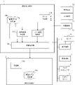
- FIG. 2 shows as a schematic block diagram the functions included in the image creating apparatus 1 according to the embodiment of the present invention.
- Each function of the image creation device 1 according to the present embodiment is realized by the CPU 11 included in the image creation device 1 shown in FIG. 1 executing a system program and controlling the operation of each part of the image creation device 1. ..
- the image creation device 1 of the present embodiment includes a data acquisition unit 100, an abnormal image creation unit 110, a label image creation unit 120, and a learning command unit 130. Further, the machine learning device 2 connected to the image creating device 1 includes a learning unit 206. Further, the RAM 13 to the non-volatile memory 14 of the image creating apparatus 1 are provided with an acquisition data storage unit 300 in advance as an area for storing data acquired by the data acquisition unit 100 from the industrial machine 3 or the like. Further, on the RAM 203 to the non-volatile memory 204 of the machine learning device 2, a learning model storage unit 209 is prepared in advance as an area for storing the learning model created by the learning unit 206.
- the data acquisition unit 100 executes a system program read from the ROM 12 by the CPU 11 included in the image creation device 1 shown in FIG. 1, mainly performs arithmetic processing using the RAM 13 and the non-volatile memory 14 by the CPU 11, and the interfaces 15 and 18. Alternatively, it is realized by performing the input control process according to 20.
- the data acquisition unit 100 may acquire the image data of the product captured by the sensor 4 attached to the industrial machine 3, or may acquire the data directly from the industrial machine 3 via the network 5. It is good, and further, the data acquired and stored by the external device 72, the fog computer 6, the cloud server 7, and the like may be acquired.
- the data acquired by the data acquisition unit 100 includes at least image data of a normal product (hereinafter referred to as normal image data).
- the data acquired by the data acquisition unit 100 may include image data of an abnormal product (hereinafter referred to as abnormal image data), but in that case, the image data acquired by the data acquisition unit 100 is a normal image. It is desirable that a label indicating that the data is data and a label indicating that the data is abnormal image data are attached.
- the data acquisition unit 100 may acquire, for example, normal image data visually confirmed by the operator based on the operation of the operator. Further, the operator's operation may be accepted so that the acquired image data can be given a label indicating that it is normal image data and a label indicating that it is abnormal image data.
- the image data of the product acquired by the data acquisition unit 100 is stored in the acquisition data storage unit 200.
- the abnormality image creation unit 110 executes a system program read from the ROM 12 by the CPU 11 included in the image creation device 1 shown in FIG. 1, and performs arithmetic processing mainly by the CPU 11 using the RAM 13 and the non-volatile memory 14. It will be realized.
- the abnormal image creating unit 110 creates abnormal image data based on the normal image data stored in the acquired data storage unit 300.
- the abnormal image creating unit 110 may create abnormal image data by superimposing a predetermined figure on a part of the image of the product in the normal image data, or may create an image with respect to the normal image data.
- Abnormal image data may be created by processing the image such as changing the hue, saturation, and lightness of a part of the image, or applying a mosaic, and further, the product in the normal image data.
- Abnormal image data may be created by adding or reducing (transforming) a predetermined figure to the image.
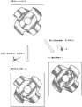
- FIG. 3 is an example of creating abnormal image data by superimposing a predetermined figure (geometric figure) on a part of the image of the product in the normal image data.
- the predetermined figure to be superimposed may be stored in the RAM 13 to the non-volatile memory 14 of the image creation device 1 in advance, or a figure having a geometric shape is created as a predetermined figure at the stage of creating the abnormal image data. You may do so. It is desirable that the color of the predetermined figure is similar to the color of the product and different from the color of the product. For example, a random number value may be calculated and determined at which position on the image of the product the predetermined figure is superimposed.
- the predetermined figure added in this way represents a portion where the processing quality of the product is deteriorated, a portion where the product is defective, and the like.
- the abnormality image creating unit 110 may perform semi-transparent composition with a predetermined transparency, or instead of superimposing the predetermined figure on the product, the abnormality image creating unit 110 may superimpose the predetermined figure on the image of the product. You may change the hue, saturation, and lightness of a predetermined range of figures to be superimposed on the image, or apply a mosaic. With either method, it is possible to express a part that has been processed (a part whose quality has deteriorated) that is different from the processing of a normal product.
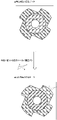
- the abnormal image creating unit 110 may perform mask processing on the predetermined figure in consideration of the shape of the product. For example, as illustrated in FIG. 4, when a part of a predetermined figure protrudes from the image of the product, the predetermined figure is masked and only the part superimposed on the image of the product is displayed. You may do so.
- the range of the product image in the normal image data may be extracted from the normal image data by a known method combined with edge processing or the like, or the normal image data may be extracted by matching processing based on CAD data or the like. It may be extracted from.
- FIG. 5 is an example of creating abnormal image data by adding a predetermined figure to the image of the product in the normal image data. It is desirable that the predetermined figure to be added is arranged adjacent to the image of the product in the normal image data.
- the shape of the predetermined figure to be added may be stored in the RAM 13 to the non-volatile memory 14 of the image creation device 1 in advance, or a geometrically shaped figure may be stored as a predetermined figure at the stage of creating the abnormal image data. You may create it.
- the predetermined figure to be added is arranged adjacent to the image of the product in the normal image data.
- the color of the predetermined figure added may be a color similar to the color of the product. Further, for example, a random number value may be calculated and determined at which position in the image of the product the predetermined figure is to be added.
- the predetermined figure added in this way expresses uncut parts of the product, large burrs, and the like.
- FIG. 6 is an example of creating abnormal image data by reducing a predetermined figure from the image of the product in the normal image data.
- the shape of the predetermined figure to be reduced may be stored in the RAM 13 to the non-volatile memory 14 of the image creation device 1 in advance, or a geometrically shaped figure may be stored as a predetermined figure at the stage of creating the abnormal image data. You may create it. It is desirable that the predetermined figure to be reduced is to reduce the edge of the image of the product in the normal image data.
- the color of the predetermined figure to be reduced may be a color similar to the background color in the normal image data. Further, for example, a random number value may be calculated and determined as to which position of the image of the product is to be reduced.
- the predetermined figure reduced in this way expresses a defect, excessive cutting, or the like of the product.
- the abnormal image creating unit 110 may create abnormal image data based on a plurality of normal image data stored in the acquired data storage unit 300, or may create a predetermined image shape based on one normal image data. You may create a plurality of abnormal image data in which the overlapping position, the shape and position of the image to be added or reduced, and the like are changed.
- the abnormality image creation unit 110 creates a sufficient number of abnormality images for the machine learning device 2 to learn the abnormality portion of the product in the abnormality image data. A sufficient number for this learning may be set in advance by the operator.
- the label image creating unit 120 executes a system program read from the ROM 12 by the CPU 11 included in the image creating device 1 shown in FIG. 1, and performs arithmetic processing mainly by the CPU 11 using the RAM 13 and the non-volatile memory 14. It will be realized.
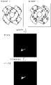
- the label image creating unit 120 creates label image data based on the difference between the normal image data and the abnormal image data created by the abnormal image creating unit 110. As illustrated in FIG. 7, the label image creating unit 120 calculates a difference between the abnormal image data created by the abnormal image creating unit 110 and the normal image data that is the basis of the abnormal image data, and makes a difference. Create an image. Then, the label image creating unit 120 creates the label image data by converting the portion other than the non-colored portion (black portion) in the difference image into white.
- the learning command unit 130 executes a system program read from the ROM 12 by the CPU 11 included in the image creation device 1 shown in FIG. 1, and mainly uses the arithmetic processing by the CPU 11 using the RAM 13 and the non-volatile memory 14 and the interface 21. It is realized by performing the input / output control process.
- the learning command unit 130 is to perform learning based on the normal image data stored in the acquired data storage unit 300, the abnormal image data created by the abnormal image creation unit 110, and the label image data created by the label image creation unit 120.
- the machine learning device 2 For example, the learning command unit 130 creates teacher data using normal image data as input data and black image data of the same size as normal image data as output data, and performs learning based on the created teacher data. Command the learning device 2.
- the learning command unit 130 creates teacher data using, for example, abnormal image data as input data and label image data created by the label image creating unit 120 as output data based on the abnormal image data, and creates teacher data.
- the machine learning device 2 is instructed to perform learning based on the above.
- the learning unit 206 included in the machine learning device 2 executes a system program read from the ROM 202 by the processor 201 included in the machine learning device 2 shown in FIG. 1, and is mainly calculated by the processor 201 using the RAM 203 and the non-volatile memory 204. It is realized by processing.
- the learning unit 206 creates a learning model by performing machine learning using the learning data received from the learning command unit 130, and stores the created learning model in the learning model storage unit 209.
- the machine learning performed by the learning unit 206 is a known supervised learning.
- the learning model created by the learning unit 206 is obtained by learning the abnormal portion in the image of the product as a label image with respect to the image of the product. Examples of the learning model created by the learning unit 206 include a multi-layer neural network and the like.
- the image creation device 1 can automatically create abnormal image data by making predetermined changes to the normal image data that can be easily collected. Therefore, when performing machine learning, the cost of collecting images of abnormal products can be significantly reduced, and efficient machine learning can be performed. Further, it is possible to create an accurate label image based on the difference between the normal image data and the abnormal image data created based on the normal image data without incurring a large cost.
Landscapes
- General Physics & Mathematics (AREA)
- Engineering & Computer Science (AREA)
- Physics & Mathematics (AREA)
- Life Sciences & Earth Sciences (AREA)
- Theoretical Computer Science (AREA)
- Health & Medical Sciences (AREA)
- Computer Vision & Pattern Recognition (AREA)
- Chemical & Material Sciences (AREA)
- Analytical Chemistry (AREA)
- Biochemistry (AREA)
- General Health & Medical Sciences (AREA)
- Immunology (AREA)
- Pathology (AREA)
- Image Analysis (AREA)
Abstract
画像作成装置は、外観検査のために用いられるモデルを作成するために必要とされる異常な製品の画像を容易に作成する。その画像作成装置は、まず正常画像データを取得し、その正常画像データに対する画像の加工を行うことで異常画像データを作成し、そして、それら正常画像データと異常画像データとの差分に基づいてラベル画像データを作成する。そうして、それら正常画像データと、異常画像データと、ラベル画像データとに基づいて学習データを作成し、該学習データに基づく機械学習を行うように機械学習装置に指令する。
Description
本発明は、画像作成装置に関し、特に外観検査を行う装置の学習に用いる画像を作成する画像作成装置に関する。
工場等の製造現場では、製造ラインにおいて製造される製品の外観検査を行っている(例えば、特許文献1)。製品の外観検査を行うためには、製品を撮像した画像に基づいて正常な製品の画像であるか、または異常な製品の画像であるかを分類する機械学習のモデルを作成しておく必要がある。
このような機械学習のモデルを作成する際には、予め、多くの正常な製品の画像と、多くの異常な製品の画像とを、それぞれ収集する。そして、収集した画像を用いて機械学習を行う。異常な製品の画像については、画像の中の更にどの部分に異常があるのかまでをも特定したいケースが多い。そのような場合には、異常な製品の画像内の異常個所を示すラベル画像を予め作成する必要がある。
製造現場で製造される製品の多くは正常な製品である。そのため、正常な製品の画像を収集することは容易である。これに対して、異常な製品が製造される頻度は比較的低い。そのため、異常な製品の画像を多数収集することは困難である。意図的に異常な製品を製造することで異常な製品の画像を多数収集することもできなくもないが、廃棄する製品を増やすことになるためコスト面で問題がある。
また、製品の異常には、例えば、削り残しや削りすぎ、工具の摩耗による表面の品質の低下、部分的な破損等、多くの種類がある。しかしながら、上記したように異常な製品が製造される頻度は低いため、これらの様々な製品の異常を検出できる機械学習のモデルを作成するために必要とされる画像を収集することはやはり困難である。更に、これらの異常が製品の異なる位置に現れる場合もあるため、異常な製品の異常個所を示すラベル画像を収集することまで考えると、多大な労力をかける必要がある。
そこで、外観検査のために用いられるモデルを作成するために必要とされる異常な製品の画像を容易に作成する技術が望まれている。
そこで、外観検査のために用いられるモデルを作成するために必要とされる異常な製品の画像を容易に作成する技術が望まれている。
本発明の一態様による画像作成装置は、正常な製品の画像から、自動的に異常な製品の画像と、異常個所を示すラベル画像とを作成することにより、上記課題を解決する。異常な製品の画像は、正常な製品の画像に対して、
a)所定の図形を重畳する、
b)一部を色相・彩度・明度を変える/モザイクをかける、または
c)一部を変形する等の加工を行うことで、
作成する。また、異常個所を示すラベル画像は、正常な製品の画像と異常な製品の画像の差分情報を使って作成する。
a)所定の図形を重畳する、
b)一部を色相・彩度・明度を変える/モザイクをかける、または
c)一部を変形する等の加工を行うことで、
作成する。また、異常個所を示すラベル画像は、正常な製品の画像と異常な製品の画像の差分情報を使って作成する。
そして、本発明の一態様は、製品の画像における異常個所の学習に用いる学習データを作成する画像作成装置であって、正常画像データを取得するデータ取得部と、正常画像データに対する画像の加工を行うことで異常画像データを作成する異常画像作成部と、前記正常画像データと、前記異常画像データとの差分に基づいてラベル画像データを作成するラベル画像作成部と、前記正常画像データと、前記異常画像データと、前記ラベル画像データとに基づいて学習データを作成し、該学習データに基づく機械学習を行うように機械学習装置に指令する学習指令部と、を備えた画像作成装置である。
本発明の一態様により、異常な製品の画像の収集コストを大幅に削減できる。また、正確なラベル画像をコストを掛けずに作成できる。
以下、本発明の実施形態を図面と共に説明する。
図1は本発明の一実施形態による画像作成装置の要部を示す概略的なハードウェア構成図である。
本発明の画像作成装置1は、例えば制御用プログラムに基づいて産業機械を制御する制御装置として実装することができ、または、制御用プログラムに基づいて産業機械を制御する制御装置に併設されたパソコンや、有線/無線のネットワークを介して制御装置と接続されたパソコン、セルコンピュータ、フォグコンピュータ6、クラウドサーバ7の上に実装することができる。本実施形態では、画像作成装置1を、ネットワーク介して制御装置と接続されたパソコンの上に実装した例を示す。
図1は本発明の一実施形態による画像作成装置の要部を示す概略的なハードウェア構成図である。
本発明の画像作成装置1は、例えば制御用プログラムに基づいて産業機械を制御する制御装置として実装することができ、または、制御用プログラムに基づいて産業機械を制御する制御装置に併設されたパソコンや、有線/無線のネットワークを介して制御装置と接続されたパソコン、セルコンピュータ、フォグコンピュータ6、クラウドサーバ7の上に実装することができる。本実施形態では、画像作成装置1を、ネットワーク介して制御装置と接続されたパソコンの上に実装した例を示す。
本実施形態による画像作成装置1が備えるCPU11は、画像作成装置1を全体的に制御するプロセッサである。CPU11は、バス22を介してROM12に格納されたシステム・プログラムを読み出し、該システム・プログラムに従って画像作成装置1全体を制御する。RAM13には一時的な計算データや表示データ、及び外部から入力された各種データ等が一時的に格納される。
不揮発性メモリ14は、例えば図示しないバッテリでバックアップされたメモリやSSD(Solid State Drive)等で構成され、画像作成装置1の電源がオフされても記憶状態が保持される。不揮発性メモリ14には、インタフェース15を介して外部機器72から読み込まれたデータ、入力装置71を介して入力されたデータ、ネットワーク5を介して産業機械3から取得されたデータ等が記憶される。記憶されるデータには、例えば産業機械3に取り付けられた視覚センサ等のセンサ4により撮像された製品の画像データが含まれていてよい。不揮発性メモリ14に記憶されたデータは、実行時/利用時にはRAM13に展開されても良い。また、ROM12には、公知の解析プログラムなどの各種システム・プログラムがあらかじめ書き込まれている。
インタフェース15は、画像作成装置1のCPU11とUSB装置等の外部機器72と接続するためのインタフェースである。外部機器72側からは、例えば各産業機械により製造される製品に係るデータ(例えば、正常な製品の画像データや、製品の形状を示すCADデータ等)を読み込むことができる。また、画像作成装置1内で編集したデータ等は、外部機器72を介してCFカード等の外部記憶手段に記憶させることができる。
インタフェース20は、画像作成装置1のCPUと有線乃至無線のネットワーク5とを接続するためのインタフェースである。ネットワーク5には、産業機械3やフォグコンピュータ、クラウドサーバ等が接続され、画像作成装置1との間で相互にデータのやり取りを行っている。
表示装置70には、メモリ上に読み込まれた各データ、プログラム等が実行された結果として得られたデータ、後述する機械学習装置2から出力されたデータ等がインタフェース17を介して入力し表示される。また、キーボードやポインティングデバイス等から構成される入力装置71は、作業者による操作に基づく指令,データ等をインタフェース18を介してCPU11に渡す。
インタフェース21は、CPU11と機械学習装置2とを接続するためのインタフェースである。機械学習装置2は、機械学習装置2全体を統御するプロセッサ201と、システム・プログラム等を記憶したROM202、機械学習に係る各処理における一時的な記憶を行うためのRAM203、及び学習モデル等の記憶に用いられる不揮発性メモリ204を備える。機械学習装置2は、インタフェース21を介して画像作成装置1で取得可能なデータ(例えば、正常な製品の画像データ、異常な製品の画像データ、ラベルデータ等)を観測することができる。また、画像作成装置1は、機械学習装置2から出力される処理結果をインタフェース21を介して取得し、取得した結果を記憶したり、表示したり、他の装置に対してネットワーク5等を介して送信したりする。
図2は、本発明の一実施形態による画像作成装置1が備える機能を概略的なブロック図として示したものである。本実施形態による画像作成装置1が備える各機能は、図1に示した画像作成装置1が備えるCPU11がシステム・プログラムを実行し、画像作成装置1の各部の動作を制御することにより実現される。
本実施形態の画像作成装置1は、データ取得部100、異常画像作成部110、ラベル画像作成部120、学習指令部130を備える。また、画像作成装置1に接続された機械学習装置2は、学習部206を備える。更に、画像作成装置1のRAM13乃至不揮発性メモリ14には、データ取得部100が産業機械3等から取得したデータを記憶するための領域として取得データ記憶部300が予め用意されている。また、機械学習装置2のRAM203乃至不揮発性メモリ204上には、学習部206が作成した学習モデルを記憶するための領域として学習モデル記憶部209が予め用意されている。
データ取得部100は、図1に示した画像作成装置1が備えるCPU11がROM12から読み出したシステム・プログラムを実行し、主としてCPU11によるRAM13、不揮発性メモリ14を用いた演算処理と、インタフェース15、18又は20による入力制御処理とが行われることで実現される。データ取得部100は、産業機械3に取り付けられたセンサ4により撮像された製品の画像データを取得するようにしてよいし、または、ネットワーク5を介して産業機械3から直接データを取得しても良いし、さらには、外部機器72や、フォグコンピュータ6、クラウドサーバ7等が取得して記憶しているデータを取得しても良い。
データ取得部100が取得するデータは、少なくとも正常な製品の画像データ(以下、正常画像データとする)を含む。データ取得部100が取得するデータは、異常な製品の画像データ(以下、異常画像データとする)を含んでいても良いが、その場合、データ取得部100が取得する画像データには、正常画像データであることを示すラベルと、異常画像データであることを示すラベルが付与されていることが望ましい。データ取得部100は、例えばオペレータが目視で確認した正常画像データを、オペレータの操作に基づいて取得するようにしても良い。また、オペレータの操作を受け付けて、取得した画像データに対して、正常画像データであることを示すラベルと、異常画像データであることを示すラベルを付与できるようにしても良い。データ取得部100が取得した製品の画像データは、取得データ記憶部200に記憶される。
データ取得部100が取得するデータは、少なくとも正常な製品の画像データ(以下、正常画像データとする)を含む。データ取得部100が取得するデータは、異常な製品の画像データ(以下、異常画像データとする)を含んでいても良いが、その場合、データ取得部100が取得する画像データには、正常画像データであることを示すラベルと、異常画像データであることを示すラベルが付与されていることが望ましい。データ取得部100は、例えばオペレータが目視で確認した正常画像データを、オペレータの操作に基づいて取得するようにしても良い。また、オペレータの操作を受け付けて、取得した画像データに対して、正常画像データであることを示すラベルと、異常画像データであることを示すラベルを付与できるようにしても良い。データ取得部100が取得した製品の画像データは、取得データ記憶部200に記憶される。
異常画像作成部110は、図1に示した画像作成装置1が備えるCPU11がROM12から読み出したシステム・プログラムを実行し、主としてCPU11によるRAM13、不揮発性メモリ14を用いた演算処理が行われることで実現される。異常画像作成部110は、取得データ記憶部300に記憶された正常画像データに基づいて、異常画像データを作成する。異常画像作成部110は、例えば、正常画像データ内の製品の画像の一部に所定の図形を重畳することで異常画像データを作成しても良いし、または、正常画像データに対して、画像の一部の色相・彩度・明度を変更したり、モザイクをかけたりする等の画像の加工を行うことで異常画像データを作成しても良いし、更には、正常画像データ内の製品の画像に所定の図形を追加乃至削減(変形)することで異常画像データを作成しても良い。
図3は、正常画像データ内の製品の画像の一部に所定の図形(幾何学的な図形)を重畳して異常画像データを作成する例である。
重畳する所定の図形は、予め画像作成装置1のRAM13乃至不揮発性メモリ14に記憶しておいても良いし、異常画像データを作成する段階で所定の図形として幾何学的形状の図形を作成するようにしても良い。所定の図形の色は、製品の色に類似した色であって、製品の色とは異なるものであることが望ましい。製品の画像のどの位置に所定の図形を重畳するかについては、例えば乱数値を算出して決定しても良い。このようにして追加された所定の図形は、製品の加工品質が低下している部分や、製品内の欠損している部分等を表現する。
重畳する所定の図形は、予め画像作成装置1のRAM13乃至不揮発性メモリ14に記憶しておいても良いし、異常画像データを作成する段階で所定の図形として幾何学的形状の図形を作成するようにしても良い。所定の図形の色は、製品の色に類似した色であって、製品の色とは異なるものであることが望ましい。製品の画像のどの位置に所定の図形を重畳するかについては、例えば乱数値を算出して決定しても良い。このようにして追加された所定の図形は、製品の加工品質が低下している部分や、製品内の欠損している部分等を表現する。
異常画像作成部110は、所定の図形を製品の画像に重畳する際には、所定の透過度で半透明合成するようにしても良いし、または、所定の図形を重畳する代わりに、製品の画像に重畳する所定の図形の範囲の色相や彩度、明度を変更したり、モザイクをかけたりしても良い。いずれの手法であっても、通常の製品の加工とは異なる加工がされた部分(品質が低下している部分)を表現することができる。
異常画像作成部110は、正常画像データ内の製品の画像の一部に所定の図形を重畳する際に、製品の形状を考えて前記所定の図形に対してマスク処理を施しても良い。例えば、図4に例示されるように、所定の図形の一部が製品の画像からはみ出る場合に、前記所定の図形に対してマスク処理を施して、製品の画像と重畳する部分のみが表示されるようにしても良い。正常画像データの内の製品の画像の範囲については、エッジ処理等を組み合わせた既知の手法で正常画像データから抽出するようにしても良いし、または、CADデータ等に基づくマッチング処理により正常画像データから抽出するようにしても良い。
図5は、正常画像データ内の製品の画像に所定の図形を追加することで異常画像データを作成する例である。
追加する所定の図形は、正常画像データ内の製品の画像に隣接して配置されることが望ましい。追加する所定の図形の形状は、予め画像作成装置1のRAM13乃至不揮発性メモリ14に記憶しておいても良いし、異常画像データを作成する段階で所定の図形として幾何学的形状の図形を作成するようにしても良い。追加する所定の図形は、正常画像データ内の製品の画像に隣接して配置されることが望ましい。追加される所定の図形の色は、製品の色に類似した色であって良い。また、製品の画像のどの位置に所定の図形を追加するかについては、例えば乱数値を算出して決定しても良い。このようにして追加された所定の図形は、製品の削り残しや大きなバリ等を表現する。
追加する所定の図形は、正常画像データ内の製品の画像に隣接して配置されることが望ましい。追加する所定の図形の形状は、予め画像作成装置1のRAM13乃至不揮発性メモリ14に記憶しておいても良いし、異常画像データを作成する段階で所定の図形として幾何学的形状の図形を作成するようにしても良い。追加する所定の図形は、正常画像データ内の製品の画像に隣接して配置されることが望ましい。追加される所定の図形の色は、製品の色に類似した色であって良い。また、製品の画像のどの位置に所定の図形を追加するかについては、例えば乱数値を算出して決定しても良い。このようにして追加された所定の図形は、製品の削り残しや大きなバリ等を表現する。
図6は、正常画像データ内の製品の画像から所定の図形を削減することで異常画像データを作成する例である。
削減する所定の図形の形状は、予め画像作成装置1のRAM13乃至不揮発性メモリ14に記憶しておいても良いし、異常画像データを作成する段階で所定の図形として幾何学的形状の図形を作成するようにしても良い。削減する所定の図形は、正常画像データの内の製品の画像の端部を削減するものであることが望ましい。削減される所定の図形の色は、正常画像データ内の背景色に類似した色であって良い。また、製品の画像のどの位置を削減するかについては、例えば乱数値を算出して決定しても良い。このようにして削減された所定の図形は、製品の欠損や削り過ぎ等を表現する。
削減する所定の図形の形状は、予め画像作成装置1のRAM13乃至不揮発性メモリ14に記憶しておいても良いし、異常画像データを作成する段階で所定の図形として幾何学的形状の図形を作成するようにしても良い。削減する所定の図形は、正常画像データの内の製品の画像の端部を削減するものであることが望ましい。削減される所定の図形の色は、正常画像データ内の背景色に類似した色であって良い。また、製品の画像のどの位置を削減するかについては、例えば乱数値を算出して決定しても良い。このようにして削減された所定の図形は、製品の欠損や削り過ぎ等を表現する。
異常画像作成部110は、取得データ記憶部300に記憶される複数の正常画像データに基づいて異常画像データを作成して良いし、または、1つの正常画像データに基づいて、所定の画像の形状や重畳する位置、追加や削減する画像の形状や位置等を変化させた複数の異常画像データを作成して良い。異常画像作成部110は、機械学習装置2が異常画像データ内の製品の異常個所を学習するために十分な数の異常画像を作成する。この学習に十分な数は、予めオペレータにより設定しておくと良い。
ラベル画像作成部120は、図1に示した画像作成装置1が備えるCPU11がROM12から読み出したシステム・プログラムを実行し、主としてCPU11によるRAM13、不揮発性メモリ14を用いた演算処理が行われることで実現される。ラベル画像作成部120は、正常画像データと、異常画像作成部110が作成した異常画像データとの差分に基づいてラベル画像データを作成する。ラベル画像作成部120は、図7に例示されるように、異常画像作成部110が作成した異常画像データと、該異常画像データの基となる正常画像データとの間で差分を演算して差分画像を作成する。そして、ラベル画像作成部120は、差分画像の中の色が無い部分(黒色の部分)以外を白色へと変換することでラベル画像データを作成する。
学習指令部130は、図1に示した画像作成装置1が備えるCPU11がROM12から読み出したシステム・プログラムを実行し、主としてCPU11によるRAM13、不揮発性メモリ14を用いた演算処理と、インタフェース21を用いた入出力制御処理が行われることで実現される。学習指令部130は、取得データ記憶部300に記憶される正常画像データ、異常画像作成部110が作成した異常画像データ、及びラベル画像作成部120が作成したラベル画像データに基づく学習を行うように機械学習装置2に指令する。学習指令部130は、例えば正常画像データを入力データとし、正常画像データと同じサイズの黒色の画像データを出力データとした教師データを作成し、作成した教師データに基づいた学習を行うように機械学習装置2に指令する。また、学習指令部130は、例えば異常画像データを入力データとし、該異常画像データに基づいてラベル画像作成部120が作成したラベル画像データを出力データとした教師データを作成し、作成した教師データに基づいた学習を行うように機械学習装置2に指令する。
機械学習装置2が備える学習部206は、図1に示した機械学習装置2が備えるプロセッサ201がROM202から読み出したシステム・プログラムを実行し、主としてプロセッサ201によるRAM203、不揮発性メモリ204を用いた演算処理が行われることにより実現される。学習部206は、学習指令部130から受け取った学習データを用いた機械学習を行うことで学習モデルを作成し、作成した学習モデルを学習モデル記憶部209に記憶する。学習部206が行う機械学習は公知の教師あり学習である。学習部206が作成する学習モデルは、製品の画像に対して、該製品の画像内の異常個所をラベル画像として学習したものとなる。学習部206が作成する学習モデルとしては、例えば多層ニューラルネットワーク等が挙げられる。
上記構成を備えた本実施形態による画像作成装置1は、容易に収集可能な正常画像データに対して所定の変更を加えることで、異常画像データを自動的に作成することができる。そのため、機械学習を行うに際して異常な製品の画像の収集コストを大幅に削減でき、効率の良い機械学習を行うことができる。また、正常画像データと、該正常画像データに基づいて作成した異常画像データとの差分に基づいて正確なラベル画像を大きなコストを掛けずに作成できる。
以上、本発明の一実施形態について説明したが、本発明は上述した実施の形態の例のみに限定されることなく、適宜の変更を加えることにより様々な態様で実施することができる。
1 画像作成装置
2 機械学習装置
3 産業機械
4 センサ
5 ネットワーク
6 フォグコンピュータ
7 クラウドサーバ
11 CPU
12 ROM
13 RAM
14 不揮発性メモリ
15,17,18,20,21 インタフェース
22 バス
70 表示装置
71 入力装置
72 外部機器
100 データ取得部
110 異常画像作成部
120 ラベル画像作成部
130 学習指令部
201 プロセッサ
202 ROM
203 RAM
204 不揮発性メモリ
206 学習部
209 学習モデル記憶部
300 取得データ記憶部
2 機械学習装置
3 産業機械
4 センサ
5 ネットワーク
6 フォグコンピュータ
7 クラウドサーバ
11 CPU
12 ROM
13 RAM
14 不揮発性メモリ
15,17,18,20,21 インタフェース
22 バス
70 表示装置
71 入力装置
72 外部機器
100 データ取得部
110 異常画像作成部
120 ラベル画像作成部
130 学習指令部
201 プロセッサ
202 ROM
203 RAM
204 不揮発性メモリ
206 学習部
209 学習モデル記憶部
300 取得データ記憶部
Claims (6)
- 製品の画像における異常個所の学習に用いる学習データを作成する画像作成装置であって、
正常画像データを取得するデータ取得部と、
正常画像データに対する画像の加工を行うことで異常画像データを作成する異常画像作成部と、
前記正常画像データと、前記異常画像データとの差分に基づいてラベル画像データを作成するラベル画像作成部と、
前記正常画像データと、前記異常画像データと、前記ラベル画像データとに基づいて学習データを作成し、該学習データに基づく機械学習を行うように機械学習装置に指令する学習指令部と、
を備えた画像作成装置。 - 前記異常画像作成部は、前記正常画像データの内の製品の画像に所定の幾何学的な図形を重畳することで前記異常画像データを作成する、
請求項1に記載の画像作成装置。 - 前記異常画像作成部は、製品の画像に対して所定の幾何学的な図形を所定の透過度で半透明合成する、
請求項2に記載の画像作成装置。 - 前記異常画像作成部は、前記正常画像データ内の製品の画像の一部の色相、彩度、又は明度を変更することで異常画像データを作成する、
請求項1に記載の画像作成装置。 - 前記異常画像作成部は、前記正常画像データ内の製品の画像の一部にモザイクをかけることで異常画像データを作成する、
請求項1に記載の画像作成装置。 - 前記異常画像作成部は、前記正常画像データ内の製品の画像の一部を変形することで異常画像データを作成する、
請求項1に記載の画像作成装置。
Applications Claiming Priority (2)
| Application Number | Priority Date | Filing Date | Title |
|---|---|---|---|
| JP2020-160594 | 2020-09-25 | ||
| JP2020160594 | 2020-09-25 |
Publications (1)
| Publication Number | Publication Date |
|---|---|
| WO2022065271A1 true WO2022065271A1 (ja) | 2022-03-31 |
Family
ID=80846509
Family Applications (1)
| Application Number | Title | Priority Date | Filing Date |
|---|---|---|---|
| PCT/JP2021/034497 Ceased WO2022065271A1 (ja) | 2020-09-25 | 2021-09-21 | 画像作成装置 |
Country Status (1)
| Country | Link |
|---|---|
| WO (1) | WO2022065271A1 (ja) |
Cited By (3)
| Publication number | Priority date | Publication date | Assignee | Title |
|---|---|---|---|---|
| JP2023077058A (ja) * | 2021-11-24 | 2023-06-05 | 株式会社キーエンス | 外観検査装置及び外観検査方法 |
| CN116778357A (zh) * | 2023-05-29 | 2023-09-19 | 北京中飞艾维航空科技有限公司 | 利用可见光缺陷识别的电力线路无人机巡检方法和系统 |
| CN118429750A (zh) * | 2024-05-27 | 2024-08-02 | 腾讯音乐娱乐科技(深圳)有限公司 | 模型训练方法、图像识别方法、计算机设备和存储介质 |
Citations (6)
| Publication number | Priority date | Publication date | Assignee | Title |
|---|---|---|---|---|
| JP2005156334A (ja) * | 2003-11-25 | 2005-06-16 | Nec Tohoku Sangyo System Kk | 疑似不良画像自動作成装置及び画像検査装置 |
| JP2019109563A (ja) * | 2017-12-15 | 2019-07-04 | オムロン株式会社 | データ生成装置、データ生成方法及びデータ生成プログラム |
| WO2019188040A1 (ja) * | 2018-03-29 | 2019-10-03 | 日本電気株式会社 | 画像処理装置、画像処理方法および画像処理プログラム |
| US20200175665A1 (en) * | 2018-12-03 | 2020-06-04 | Samsung Electronics Co., Ltd. | Semiconductor wafer fault analysis system and operation method thereof |
| JP2020125918A (ja) * | 2019-02-01 | 2020-08-20 | 株式会社キーエンス | 画像検査装置 |
| JP2020125919A (ja) * | 2019-02-01 | 2020-08-20 | 株式会社キーエンス | 画像検査装置 |
-
2021
- 2021-09-21 WO PCT/JP2021/034497 patent/WO2022065271A1/ja not_active Ceased
Patent Citations (6)
| Publication number | Priority date | Publication date | Assignee | Title |
|---|---|---|---|---|
| JP2005156334A (ja) * | 2003-11-25 | 2005-06-16 | Nec Tohoku Sangyo System Kk | 疑似不良画像自動作成装置及び画像検査装置 |
| JP2019109563A (ja) * | 2017-12-15 | 2019-07-04 | オムロン株式会社 | データ生成装置、データ生成方法及びデータ生成プログラム |
| WO2019188040A1 (ja) * | 2018-03-29 | 2019-10-03 | 日本電気株式会社 | 画像処理装置、画像処理方法および画像処理プログラム |
| US20200175665A1 (en) * | 2018-12-03 | 2020-06-04 | Samsung Electronics Co., Ltd. | Semiconductor wafer fault analysis system and operation method thereof |
| JP2020125918A (ja) * | 2019-02-01 | 2020-08-20 | 株式会社キーエンス | 画像検査装置 |
| JP2020125919A (ja) * | 2019-02-01 | 2020-08-20 | 株式会社キーエンス | 画像検査装置 |
Cited By (4)
| Publication number | Priority date | Publication date | Assignee | Title |
|---|---|---|---|---|
| JP2023077058A (ja) * | 2021-11-24 | 2023-06-05 | 株式会社キーエンス | 外観検査装置及び外観検査方法 |
| JP7770168B2 (ja) | 2021-11-24 | 2025-11-14 | 株式会社キーエンス | 外観検査装置及び外観検査方法 |
| CN116778357A (zh) * | 2023-05-29 | 2023-09-19 | 北京中飞艾维航空科技有限公司 | 利用可见光缺陷识别的电力线路无人机巡检方法和系统 |
| CN118429750A (zh) * | 2024-05-27 | 2024-08-02 | 腾讯音乐娱乐科技(深圳)有限公司 | 模型训练方法、图像识别方法、计算机设备和存储介质 |
Similar Documents
| Publication | Publication Date | Title |
|---|---|---|
| WO2022065271A1 (ja) | 画像作成装置 | |
| US10303495B2 (en) | Robot system including CNC and robot controller connected through communication network | |
| US10984523B2 (en) | Seam inspection apparatus | |
| EP2776896B1 (en) | Method and system for position control based on automated defect detection feedback | |
| WO2022065273A1 (ja) | 外観検査のためのモデル作成装置及び外観検査装置 | |
| DE102020134680B4 (de) | Verfahren und Anordnung zur Qualitätsprüfung eines Objekts | |
| JP2001501344A (ja) | 実時間プロセス制御システム用の管理図面を自動的に生成するためのシステム及び方法 | |
| JP2021131853A (ja) | Arオーバーレイを使用した変化検出方法及びシステム | |
| EP3882856A1 (de) | Verfahren und vorrichtung zum bestimmen einer pose | |
| CN111435400A (zh) | 一种零件的修复方法、修复装置及3d打印机 | |
| WO2023174872A1 (de) | Prüfen einer sicherheitskonfiguration eines roboters | |
| US20200082281A1 (en) | Verification device | |
| JP7502448B2 (ja) | 検査装置 | |
| DE102020211053A1 (de) | Annotationsvorrichtung | |
| WO2022065272A1 (ja) | 外観検査のためのモデル作成装置及び外観検査装置 | |
| CN110097526B (zh) | 工件图像生成装置 | |
| DE112022006723T5 (de) | Lehrunterstützungsvorrichtung, arbeitssystem, lehrunterstützungsverfahren und speichermedium | |
| JP2021086219A (ja) | 協調作業システム、解析収集装置および解析プログラム | |
| DE112021007102T5 (de) | Programmerzeugungsvorrichtung und Robotersteuerungsvorrichtung | |
| JP7415046B2 (ja) | 画像処理装置、及びコンピュータが読み取り可能な記憶媒体 | |
| DE112021008005T5 (de) | Lehrvorrichtung und robotersystem | |
| JP7701553B2 (ja) | 外観検査装置、外観検査方法、及びコンピュータ読み取り可能な記録媒体 | |
| DE102022202564B4 (de) | Prüfen einer Sicherheitskonfiguration eines Roboters | |
| WO2023218537A1 (ja) | 対象領域抽出装置、方法、及びシステム | |
| DE102022202571B3 (de) | Prüfen einer vorgegebenen Bahn eines Roboters |
Legal Events
| Date | Code | Title | Description |
|---|---|---|---|
| 121 | Ep: the epo has been informed by wipo that ep was designated in this application |
Ref document number: 21872400 Country of ref document: EP Kind code of ref document: A1 |
|
| NENP | Non-entry into the national phase |
Ref country code: DE |
|
| 122 | Ep: pct application non-entry in european phase |
Ref document number: 21872400 Country of ref document: EP Kind code of ref document: A1 |
|
| NENP | Non-entry into the national phase |
Ref country code: JP |