WO2022064827A1 - 情報処理装置、情報処理方法およびプログラム - Google Patents
情報処理装置、情報処理方法およびプログラム Download PDFInfo
- Publication number
- WO2022064827A1 WO2022064827A1 PCT/JP2021/027062 JP2021027062W WO2022064827A1 WO 2022064827 A1 WO2022064827 A1 WO 2022064827A1 JP 2021027062 W JP2021027062 W JP 2021027062W WO 2022064827 A1 WO2022064827 A1 WO 2022064827A1
- Authority
- WO
- WIPO (PCT)
- Prior art keywords
- unit
- recognition
- information processing
- sensor
- control unit
- Prior art date
Links
Images


Classifications
-
- G—PHYSICS
- G06—COMPUTING; CALCULATING OR COUNTING
- G06F—ELECTRIC DIGITAL DATA PROCESSING
- G06F3/00—Input arrangements for transferring data to be processed into a form capable of being handled by the computer; Output arrangements for transferring data from processing unit to output unit, e.g. interface arrangements
- G06F3/01—Input arrangements or combined input and output arrangements for interaction between user and computer
- G06F3/017—Gesture based interaction, e.g. based on a set of recognized hand gestures
-
- G—PHYSICS
- G06—COMPUTING; CALCULATING OR COUNTING
- G06V—IMAGE OR VIDEO RECOGNITION OR UNDERSTANDING
- G06V10/00—Arrangements for image or video recognition or understanding
- G06V10/94—Hardware or software architectures specially adapted for image or video understanding
-
- G—PHYSICS
- G06—COMPUTING; CALCULATING OR COUNTING
- G06F—ELECTRIC DIGITAL DATA PROCESSING
- G06F3/00—Input arrangements for transferring data to be processed into a form capable of being handled by the computer; Output arrangements for transferring data from processing unit to output unit, e.g. interface arrangements
- G06F3/01—Input arrangements or combined input and output arrangements for interaction between user and computer
- G06F3/011—Arrangements for interaction with the human body, e.g. for user immersion in virtual reality
- G06F3/012—Head tracking input arrangements
-
- G—PHYSICS
- G06—COMPUTING; CALCULATING OR COUNTING
- G06F—ELECTRIC DIGITAL DATA PROCESSING
- G06F3/00—Input arrangements for transferring data to be processed into a form capable of being handled by the computer; Output arrangements for transferring data from processing unit to output unit, e.g. interface arrangements
- G06F3/01—Input arrangements or combined input and output arrangements for interaction between user and computer
- G06F3/011—Arrangements for interaction with the human body, e.g. for user immersion in virtual reality
- G06F3/013—Eye tracking input arrangements
-
- G—PHYSICS
- G06—COMPUTING; CALCULATING OR COUNTING
- G06F—ELECTRIC DIGITAL DATA PROCESSING
- G06F3/00—Input arrangements for transferring data to be processed into a form capable of being handled by the computer; Output arrangements for transferring data from processing unit to output unit, e.g. interface arrangements
- G06F3/01—Input arrangements or combined input and output arrangements for interaction between user and computer
- G06F3/011—Arrangements for interaction with the human body, e.g. for user immersion in virtual reality
- G06F3/014—Hand-worn input/output arrangements, e.g. data gloves
-
- G—PHYSICS
- G06—COMPUTING; CALCULATING OR COUNTING
- G06F—ELECTRIC DIGITAL DATA PROCESSING
- G06F3/00—Input arrangements for transferring data to be processed into a form capable of being handled by the computer; Output arrangements for transferring data from processing unit to output unit, e.g. interface arrangements
- G06F3/01—Input arrangements or combined input and output arrangements for interaction between user and computer
- G06F3/016—Input arrangements with force or tactile feedback as computer generated output to the user
-
- G—PHYSICS
- G06—COMPUTING; CALCULATING OR COUNTING
- G06F—ELECTRIC DIGITAL DATA PROCESSING
- G06F3/00—Input arrangements for transferring data to be processed into a form capable of being handled by the computer; Output arrangements for transferring data from processing unit to output unit, e.g. interface arrangements
- G06F3/01—Input arrangements or combined input and output arrangements for interaction between user and computer
- G06F3/03—Arrangements for converting the position or the displacement of a member into a coded form
- G06F3/033—Pointing devices displaced or positioned by the user, e.g. mice, trackballs, pens or joysticks; Accessories therefor
- G06F3/0346—Pointing devices displaced or positioned by the user, e.g. mice, trackballs, pens or joysticks; Accessories therefor with detection of the device orientation or free movement in a 3D space, e.g. 3D mice, 6-DOF [six degrees of freedom] pointers using gyroscopes, accelerometers or tilt-sensors
-
- G—PHYSICS
- G06—COMPUTING; CALCULATING OR COUNTING
- G06V—IMAGE OR VIDEO RECOGNITION OR UNDERSTANDING
- G06V10/00—Arrangements for image or video recognition or understanding
- G06V10/70—Arrangements for image or video recognition or understanding using pattern recognition or machine learning
- G06V10/77—Processing image or video features in feature spaces; using data integration or data reduction, e.g. principal component analysis [PCA] or independent component analysis [ICA] or self-organising maps [SOM]; Blind source separation
- G06V10/776—Validation; Performance evaluation
-
- G—PHYSICS
- G06—COMPUTING; CALCULATING OR COUNTING
- G06V—IMAGE OR VIDEO RECOGNITION OR UNDERSTANDING
- G06V10/00—Arrangements for image or video recognition or understanding
- G06V10/70—Arrangements for image or video recognition or understanding using pattern recognition or machine learning
- G06V10/77—Processing image or video features in feature spaces; using data integration or data reduction, e.g. principal component analysis [PCA] or independent component analysis [ICA] or self-organising maps [SOM]; Blind source separation
- G06V10/80—Fusion, i.e. combining data from various sources at the sensor level, preprocessing level, feature extraction level or classification level
- G06V10/803—Fusion, i.e. combining data from various sources at the sensor level, preprocessing level, feature extraction level or classification level of input or preprocessed data
-
- G—PHYSICS
- G06—COMPUTING; CALCULATING OR COUNTING
- G06V—IMAGE OR VIDEO RECOGNITION OR UNDERSTANDING
- G06V20/00—Scenes; Scene-specific elements
- G06V20/20—Scenes; Scene-specific elements in augmented reality scenes
-
- G—PHYSICS
- G06—COMPUTING; CALCULATING OR COUNTING
- G06V—IMAGE OR VIDEO RECOGNITION OR UNDERSTANDING
- G06V20/00—Scenes; Scene-specific elements
- G06V20/50—Context or environment of the image
- G06V20/52—Surveillance or monitoring of activities, e.g. for recognising suspicious objects
-
- G—PHYSICS
- G06—COMPUTING; CALCULATING OR COUNTING
- G06V—IMAGE OR VIDEO RECOGNITION OR UNDERSTANDING
- G06V40/00—Recognition of biometric, human-related or animal-related patterns in image or video data
- G06V40/10—Human or animal bodies, e.g. vehicle occupants or pedestrians; Body parts, e.g. hands
Definitions
- This disclosure relates to information processing devices, information processing methods and programs.
- the operation unit activated between the first operation unit and the second operation unit related to the recognition of the recognition target existing in the real space.
- the first sensor which comprises a control unit for controlling the switching of the above and obtains the first data in which the recognition target is recognized, is attached to the first part of the user's body and the recognition target is recognized.
- the second sensor for obtaining the data of the above is provided with an information processing apparatus attached to a second part of the body different from the first part.
- the processor is located between the first operating unit and the second operating unit related to the recognition of the recognition target existing in the real space based on the detection result of the detection target.
- the first sensor for obtaining the first data in which the recognition target is recognized is attached to the first part of the user's body, and the recognition target is mounted on the first part of the user's body.
- a second sensor that obtains the second data to be recognized is provided with an information processing method that is attached to a second part of the body that is different from the first part.
- the computer is placed between the first moving unit and the second moving unit related to the recognition of the recognition target existing in the real space based on the detection result of the detection target.
- the first sensor which includes a control unit that controls switching of the operation unit activated in the above and obtains the first data in which the recognition target is recognized, is attached to the first part of the user's body and is the recognition target.
- the second sensor for obtaining the second data to be recognized is provided with a program for functioning as an information processing device, which is attached to a second part of the body different from the first part.
- a plurality of components having substantially the same or similar functional configurations may be distinguished by adding different numbers after the same reference numerals. However, if it is not necessary to particularly distinguish each of the plurality of components having substantially the same or similar functional configurations, only the same reference numerals are given. Further, similar components of different embodiments may be distinguished by adding different alphabets after the same reference numerals. However, if it is not necessary to distinguish each of the similar components, only the same reference numerals are given.
- FIG. 1 is an explanatory diagram for explaining an example of a schematic configuration of an information processing system according to an embodiment of the present disclosure, and various contents are provided to a user by applying so-called AR (Augmented Reality) technology. An example of the case of presenting is shown.
- AR Augmented Reality
- reference numeral m111 schematically indicates an object (for example, a real object) located in real space.
- reference numerals v131 and v133 schematically indicate virtual contents (for example, virtual objects) presented so as to be superimposed on the real space. That is, the information processing system 1 according to the present embodiment superimposes a virtual object on an object in the real space such as the real object m111 and presents it to the user based on, for example, AR technology.
- both a real object and a virtual object are presented together in order to make it easier to understand the characteristics of the information processing system according to the present embodiment.
- the information processing system 1 includes an information processing device 10 and an input / output device 20.
- the information processing device 10 and the input / output device 20 are configured to be able to send and receive information to and from each other via a predetermined network.
- the type of network connecting the information processing device 10 and the input / output device 20 is not particularly limited.
- the network may be configured by a so-called wireless network such as a network based on the Wi-Fi® standard.
- the network may be configured by the Internet, a dedicated line, a LAN (Local Area Network), a WAN (Wide Area Network), or the like.
- the network may include a plurality of networks, and at least a part thereof may be configured as a wired network.
- the input / output device 20 is configured to acquire various input information and present various output information to the user holding the input / output device 20. Further, the presentation of the output information by the input / output device 20 is controlled by the information processing device 10 based on the input information acquired by the input / output device 20. For example, the input / output device 20 acquires information for recognizing the real object m111 (for example, an image of the captured real space) as input information, and outputs the acquired information to the information processing device 10. The information processing device 10 recognizes the position of the real object m111 in the real space based on the information acquired from the input / output device 20, and causes the input / output device 20 to present the virtual objects v131 and v133 based on the recognition result. By such control, the input / output device 20 can present the virtual objects v131 and v133 to the user so that the virtual objects v131 and v133 are superimposed on the real object m111 based on the so-called AR technology. Become.
- the input / output device 20 is configured as a so-called head-mounted device that the user wears on at least a part of the head and uses, for example, and may be configured to be able to detect the line of sight of the user. ..
- the information processing apparatus 10 is, for example, a target desired by the user (for example, a real object m111, virtual objects v131 and v133, etc.) based on the detection result of the user's line of sight by the input / output apparatus 20.
- the target may be specified as an operation target.
- the information processing device 10 may specify a target to which the user's line of sight is directed as an operation target by using a predetermined operation on the input / output device 20 as a trigger. As described above, the information processing device 10 may provide various services to the user via the input / output device 20 by specifying the operation target and executing the process associated with the operation target.
- the information processing device 10 Based on the input information acquired by the input / output device 20, the information processing device 10 uses the movement of the position and posture of the user's arm, palm, and finger joint (for example, change in position or orientation, gesture, etc.) as the user's operation input. It recognizes and executes various processes according to the recognition result of the operation input. As a specific example, the input / output device 20 acquires information for recognizing a user's arm, palm, and finger joint (for example, an image of an captured hand) as input information, and the acquired information is an information processing device. Output to 10.
- the input / output device 20 acquires information for recognizing a user's arm, palm, and finger joint (for example, an image of an captured hand) as input information, and the acquired information is an information processing device. Output to 10.
- the information processing device 10 estimates the position and posture of the arm, palm, and finger joint based on the information acquired from the input / output device 20, recognizes the movement (for example, gesture), and responds to the recognition result of the movement. Recognize instructions from the user (that is, user operation input). Then, the information processing apparatus 10 may control the display of the virtual object presented to the user (for example, the display position or posture of the virtual object) according to the recognition result of the operation input of the user.
- the "user operation input” may be regarded as an input corresponding to an instruction from the user, that is, an input reflecting the intention of the user, as described above.
- “user operation input” may be simply referred to as "user input”.
- the information processing device 10 performs movements (for example, changes in position and orientation, gestures, etc.) of at least a part of the user's body other than the hands of the user based on the input information acquired by the input / output device 20. It may be recognized as an operation input and various processes may be executed according to the recognition result of the operation input.
- FIG. 2 shows an example of a case where various contents are presented in response to a user's hand movement, that is, a user's operation input by applying a so-called AR (Augmented Reality) technology.
- AR Augmented Reality
- the information processing system 1 includes an information processing device 10, an input / output device 20, and a wearable device 30.
- the information processing device 10, the input / output device 20, and the wearable device 30 are configured to be capable of transmitting and receiving information to and from each other via a predetermined network.
- the type of network connecting the information processing device 10, the input / output device 20, and the wearable device 30 is not particularly limited.
- the input / output device 20 acquires information for detecting the position and posture of the palm-mounted wearable device 30 as input information (for example, with relatively low accuracy), and the acquired input information is used in the information processing device 10. Output.
- the acceleration information and the angular velocity information output by the IMU (Inertial Measurement Unit) of the wearable device 30 are used as the input information.
- the input information is not limited to the information output by the IMU.
- the input information may be information output by the magnetic sensor, as will be described later.
- the wearable device 30 includes an optical marker arranged in a predetermined pattern (for example, an active marker of LED (Light Emitting Diode) emission, a passive marker of a retroreflective material, etc.). Since the wearable device 30 shown in FIG. 2 is simply shown, an optical marker is not shown, but the optical marker will be described in detail later with reference to FIG.
- the input / output device 20 acquires an image of the optical marker.
- the information processing device 10 acquires the position and orientation of the wearable device 30 (for example, with relatively high accuracy) based on the input information of the captured image of the optical marker acquired by the input / output device 20.
- the position and posture of the wearable device 30 can be obtained (for example, with relatively low accuracy).
- the input / output device 20 and the information processing device 10 are shown as different devices in FIGS. 1 and 2, the input / output device 20 and the information processing device 10 may be integrally configured. .. The details of the configuration and processing of the input / output device 20 and the information processing device 10 will be described later separately.
- FIGS. 1 and 2 an example of a schematic configuration of the information processing system 1 according to the embodiment of the present disclosure has been described above.
- FIG. 3 is an explanatory diagram for explaining an example of a schematic configuration of the input / output device 20 according to the present embodiment.
- the input / output device 20 is configured as a so-called head-mounted device that is worn and used by the user on at least a part of the head, and is at least one of the lenses 293a and 293b. It is configured as a transmissive display (display unit 211). Further, the input / output device 20 includes image pickup units 201a and 201b, an operation unit 207, and a holding unit 291 corresponding to a frame of eyeglasses. Further, the input / output device 20 may include image pickup units 203a and 203b. In the following, various explanations will be given assuming that the input / output device 20 includes the image pickup units 203a and 203b.
- the holding unit 291 may attach the display unit 211, the imaging units 201a and 201b, the imaging units 203a and 203b, and the operation unit 207 to the user's head. Hold it so that it has a predetermined positional relationship with the unit.
- the input / output device 20 may include a sound collecting unit for collecting the user's voice.
- the lens 293a corresponds to the lens on the right eye side
- the lens 293b corresponds to the lens on the left eye side. That is, the holding unit 291 holds the display unit 211 so that the display unit 211 (in other words, the lenses 293a and 293b) is located in front of the user's eyes when the input / output device 20 is attached.
- the image pickup units 201a and 201b are configured as so-called stereo cameras, and when the input / output device 20 is attached to the user's head, the image pickup unit 201a and 201b face the direction in which the user's head faces (that is, in front of the user). As such, they are each held by the holding unit 291. At this time, the imaging unit 201a is held in the vicinity of the user's right eye, and the imaging unit 201b is held in the vicinity of the user's left eye. Based on such a configuration, the imaging units 201a and 201b image a subject (in other words, a real object located in the real space) located in front of the input / output device 20 from different positions.
- the input / output device 20 acquires an image of the subject located in front of the user, and based on the parallax between the images captured by the imaging units 201a and 201b, the input / output device 20 (and by extension, the user's) It is possible to calculate the distance to the subject from the position of the viewpoint).
- the configuration and method thereof are not particularly limited.
- the distance between the input / output device 20 and the subject may be measured based on a method such as multi-camera stereo, moving parallax, TOF (Time Of Light), Structured Light, or the like.
- TOF is a subject based on the measurement result by projecting light such as infrared rays onto the subject and measuring the time until the projected light is reflected by the subject and returned for each pixel.
- This is a method of obtaining an image (so-called distance image) including the distance (depth) up to.
- Structured Light irradiates a subject with a pattern by light such as infrared rays, and by imaging the pattern, the distance including the distance (depth) to the subject is based on the change of the pattern obtained from the imaging result. This is a method for obtaining an image.
- the moving parallax is a method of measuring the distance to the subject based on the parallax even in a so-called monocular camera. Specifically, by moving the camera, the subject is imaged from different viewpoints, and the distance to the subject is measured based on the parallax between the captured images.
- the imaging unit for example, a monocular camera, a stereo camera, etc.
- the configuration of the imaging unit may be changed according to the distance measurement method.
- the imaging units 203a and 203b are held by the holding unit 291 so that the user's eyeball is positioned within the respective imaging range when the input / output device 20 is attached to the user's head.
- the imaging unit 203a is held so that the user's right eye is located within the imaging range. Based on such a configuration, the line of sight of the right eye is directed based on the image of the eyeball of the right eye captured by the imaging unit 203a and the positional relationship between the imaging unit 203a and the right eye. It becomes possible to recognize the direction.
- the imaging unit 203b is held so that the left eye of the user is located within the imaging range.
- the input / output device 20 shows a configuration including both the image pickup units 203a and 203b, but only one of the image pickup units 203a and 203b may be provided.
- the IR (Infrared) light source 201c and the IR image pickup unit 201d for hand position detection are for obtaining the position and posture of the wearable device 30 (as viewed from the input / output device 20).
- the infrared light (for example, 940 nm) emitted from the IR light source 201c is reflected by the optical marker (FIG. 4) of the retroreflective material of the wearable device 30 and is imaged (or IR) by the IR image pickup unit 201d.
- the optical marker 320 (FIG. 4) is an IR LED (for example, with a wavelength of 940 nm), which may be configured to emit light by itself).
- the IR imaging unit 201d includes a bandpass filter that allows only infrared light (as an example, centered on the 940 nm band) to pass through, and only the bright spot of the optical marker 320 (FIG. 4) is imaged. From the image of the bright spot, it is possible to obtain the relative position and orientation of the wearable device 30 from the input / output device 20 (as an example, with relatively high accuracy).
- the operation unit 207 is configured to receive an operation from the user on the input / output device 20.
- the operation unit 207 may be configured by an input device such as a touch panel or a button.
- the operation unit 207 is held at a predetermined position of the input / output device 20 by the holding unit 291. For example, in the example shown in FIG. 3, the operation unit 207 is held at a position corresponding to the temple of the glasses.
- the input / output device 20 is provided with an inertial measurement unit 220 (FIG. 5) (IMU) including an acceleration sensor, a gyro sensor (angular velocity sensor), and the like (not shown).
- IMU inertial measurement unit
- the input / output device 20 can acquire the acceleration information and the angular velocity information output by the IMU. Then, based on the acceleration information and the angular velocity information, the movement of the head of the user wearing the input / output device 20 (in other words, the movement of the input / output device 20 itself) can be detected.
- the information processing device 10 acquires acceleration information and angular velocity information output by the IMU of the input / output device 20, calculates the position and attitude of the input / output device 20 by inertial navigation, and causes a drift at that time. By correcting the error with the regression model, it is possible to estimate the position information and the posture information of the input / output device 20 and acquire the position and the posture of the head of the user.
- the input / output device 20 can recognize changes in its own position and posture in the real space according to the movement of the user's head. Further, at this time, based on the so-called AR technology, the input / output device 20 displays the content on the display unit 211 so that the virtual content (that is, the virtual object) is superimposed on the real object located in the real space. It is also possible to present it. Further, at this time, the input / output device 20 may estimate its own position and posture (that is, its own position) in the real space based on, for example, a technique called SLAM (Simultaneus Localization And Mapping). The estimation result may be used for presenting a virtual object.
- SLAM Simultaneus Localization And Mapping
- SLAM is a technology that performs self-position estimation and environment map creation in parallel by using an image pickup unit such as a camera, various sensors, an encoder, and the like.
- an image pickup unit such as a camera, various sensors, an encoder, and the like.
- the three-dimensional shape of the captured scene (or subject) is sequentially restored based on the moving image captured by the imaging unit. Then, by associating the restored result of the captured scene with the detection result of the position and posture of the imaging unit, a map of the surrounding environment can be created, and the position and position of the imaging unit (and thus the input / output device 20) in the environment and Posture estimation is performed.
- the position and orientation of the image pickup unit can be estimated as information indicating a relative change based on the detection result of the sensor by, for example, providing various sensors such as an acceleration sensor and an angular velocity sensor in the input / output device 20. Is possible.
- the method is not necessarily limited to the method based on the detection results of various sensors such as an acceleration sensor and an angular velocity sensor.
- HMD Head Mounted Display
- the see-through type HMD uses, for example, a half mirror or a transparent light guide plate to hold a virtual image optical system including a transparent light guide portion in front of the user's eyes and display an image inside the virtual image optical system. Therefore, the user wearing the see-through type HMD can see the outside scenery while visually recognizing the image displayed inside the virtual image optical system.
- the see-through HMD is, for example, based on AR technology, with respect to an optical image of a real object located in the real space according to the recognition result of at least one of the position and the posture of the see-through HMD. It is also possible to superimpose an image of a virtual object.
- the see-through type HMD there is a so-called glasses-type wearable device in which a portion corresponding to a lens of glasses is configured as a virtual image optical system.
- the input / output device 20 shown in FIG. 3 corresponds to an example of a see-through type HMD.
- the video see-through type HMD When the video see-through type HMD is attached to the user's head or face, it is attached so as to cover the user's eyes, and a display unit such as a display is held in front of the user's eyes. Further, the video see-through type HMD has an image pickup unit for capturing an image of the surrounding landscape, and displays an image of the landscape in front of the user captured by the image pickup unit on the display unit. With such a configuration, it is difficult for the user wearing the video see-through type HMD to directly see the external scenery, but it is possible to confirm the external scenery from the image displayed on the display unit. Become.
- the video see-through type HMD superimposes a virtual object on the image of the external landscape according to the recognition result of at least one of the position and the posture of the video see-through type HMD based on, for example, AR technology. You may let me.
- a projection unit is held in front of the user's eyes, and the image is projected from the projection unit toward the user's eyes so that the image is superimposed on the external landscape. More specifically, in the retinal projection type HMD, an image is directly projected from the projection unit onto the retina of the user's eye, and the image is imaged on the retina. With such a configuration, even in the case of a user with myopia or hyperopia, a clearer image can be visually recognized. In addition, the user wearing the retinal projection type HMD can see the external landscape in the field of view while visually recognizing the image projected from the projection unit.
- the retinal projection type HMD is an optical image of a real object located in the real space according to the recognition result of at least one of the position and the posture of the retinal projection type HMD based on, for example, AR technology. It is also possible to superimpose an image of a virtual object on the image.
- the input / output device 20 according to the present embodiment may be configured as an HMD called an immersive HMD.
- the immersive HMD is worn so as to cover the user's eyes, and a display unit such as a display is held in front of the user's eyes. Therefore, it is difficult for the user wearing the immersive HMD to directly see the external scenery (that is, the scenery in the real world), and only the image displayed on the display unit is in the field of view. With such a configuration, the immersive HMD can give an immersive feeling to the user who is viewing the image.
- FIG. 4 is an explanatory diagram for explaining an example of a schematic configuration of the wearable device 30 according to the present embodiment.
- the wearable device 30 is configured as a so-called wearable device that the user wears on the palm of his / her hand.
- the wearable device 30 is configured as a so-called palm vest type device.
- the wearable device 30 includes an imaging unit (palm side) 301 and an imaging unit (back side) 302, and the imaging unit (palm side) 301 holds the fingers (fingers) of the hand on which the wearable device 30 is attached.
- the imaging unit (back side) 302 is arranged on the back side of the hand so that the image can be taken from the palm side, and the image pickup unit (back side) 302 is arranged on the back side of the hand so that the finger (finger) of the hand to which the wearable device 30 is attached can be imaged from the back side of the hand. ..
- the image pickup unit (palm side) 301 and the image pickup unit (back side) 302 are each configured as a TOF sensor, and the depth (distance to the finger) can be obtained from the depth image obtained by the TOF sensor. ..
- the types of sensors of the imaging unit (palm side) 301 and the imaging unit (back side) 302 are not limited to the TOF sensor, and may be other sensors capable of obtaining depth.
- one or both of the image pickup unit (palm side) 301 and the image pickup unit (back side) 302 may be a 2D sensor such as an IR sensor.
- the wearable device 30 includes a plurality of optical markers 320 whose surface is a retroreflective material, an inertial measurement unit 303 (FIG. 5), and a vibration presenting unit 311.
- the finger F1 is shown.
- the relative position and posture of the fingers F1 are shown as the position / posture R1.
- the relative position (as viewed from the image pickup unit 201) can be represented by the coordinates in the camera coordinate system with respect to the image pickup unit 201.
- the image pickup unit 201 used as a reference is not particularly limited (for example, the image pickup unit 201a may be a reference).
- the relative position and posture of the wearable device 30 are shown as the position / posture R2.
- the relative position and posture (as viewed from the wearable device 30) of the imaging unit (palm side) 301 are shown as the position / posture R3.
- the relative position and posture of the finger F1 (as viewed from the imaging unit (palm side) 301) are shown as the position posture R4.
- the relative position and posture (as viewed from the wearable device 30) of the imaging unit (back side of the hand) 302 are shown as the position / posture R5.
- the relative position and posture of the finger F1 are shown as the position posture R6.
- FIG. 4 shows the finger F1 corresponding to the middle finger as an example of the finger.
- fingers other than the middle finger that is, the thumb, index finger, ring finger and little finger
- fingers other than the middle finger can be treated as fingers as well as the finger F1 corresponding to the middle finger.
- the optical marker 320 reflects the irradiation light of the IR light source 201c of the input / output device 20.
- the reflected light is imaged by the IR image pickup unit 201d, and the relative position and posture (as viewed from the image pickup unit 201) of the wearable device 30 is obtained (for example, with relatively high accuracy) from the bright spot of the obtained image.
- the optical marker 320 is not limited to a passive marker using a retroreflective material, but may be an active marker using an IR LED. When the optical marker 320 is an active marker, the IR light source 201c of the input / output device 20 is unnecessary.
- the inertial measurement unit 303 (FIG. 5) is configured by, for example, an IMU, and can acquire acceleration information and angular velocity information output by the IMU, similarly to the IMU included in the input / output unit 20. Based on the acceleration information and the angular velocity information, the movement of the hand of the user wearing the wearable device 30 (in other words, the movement of the wearable device 30 itself) can be detected.
- the information processing device 10 acquires acceleration information and angular velocity information output by the IMU sensor of the wearable device 30, calculates the position and attitude of the wearable device 30 by inertial navigation, and causes a drift error at that time. Is corrected by the regression model, it is possible to estimate the position information and the posture information of the wearable device 30 and acquire the position and the posture of the user's hand.
- the vibration presenting unit 311 presents a tactile sensation to the user's hand by driving a vibration actuator that generates vibration.
- a vibration actuator specifically, a translational actuator such as a voice coil motor or an LRA (Linear Resonant Actuator) or a rotary actuator such as an eccentric motor is used. It can be driven in the frequency range, and high vibration expressive power can be obtained.
- the oscillating actuator is driven by applying a time-varying analog waveform voltage close to the audio signal. It is conceivable to install the vibration actuators at a plurality of locations according to the vibration intensity to be presented and the presentation site.
- the vibration actuator directly on the part where vibration is to be presented (palm, etc.)
- the vibration propagation characteristics and the tactile sensitivity of the hand differ for each frequency. Based on this, it is possible to make the palm shape present a tactile sensation.
- FIG. 5 is a block diagram showing an example of the functional configuration of the information processing system 1 according to the present embodiment.
- the information processing system 1 includes the information processing device 10, the input / output device 20, and the wearable device 30, and the information processing device 10, the input / output device 20, and the wearable device 30 are included.
- the configuration of each of the devices 30 will be described in more detail.
- the information processing system 1 may include a storage unit 190.
- the input / output unit 20 includes image pickup units 201a, 201b and 201d, an output unit 210, and an inertial measurement unit 220 (IMU).
- the output unit 210 includes a display unit 211. Further, the output unit 210 may include an acoustic output unit 213.
- the image pickup units 201a, 201b and 201d correspond to the image pickup units 201a, 201b and 201d described with reference to FIG. When the imaging units 201a, 201b and 201d are not particularly distinguished, they may be simply referred to as "imaging unit 201".
- the display unit 211 corresponds to the display unit 211 described with reference to FIG. 2.
- the acoustic output unit 213 is composed of an acoustic device such as a speaker, and outputs voice or sound according to the information to be output.
- the input / output device 20 also includes an operation unit 207, image pickup units 203a and 203b, a holding unit 291 and the like.
- the wearable device 30 includes an imaging unit (palm side) 301, an imaging unit (back side) 302, an inertial measurement unit 303 (IMU), and an output unit 310.
- the output unit 310 includes a vibration presentation unit 311.
- the vibration presenting unit 311 is composed of a vibration actuator and presents vibration according to information to be output.
- the wearable device 30 also includes an optical marker 320 and the like.
- the information processing apparatus 10 includes a stereo depth calculation unit 101, a finger joint recognition unit 103, a finger joint recognition unit 115, a finger joint recognition unit 117, and a finger joint recognition integration unit 119. .. Further, the information processing apparatus 10 includes a wearable device position / attitude estimation unit 109, an inertial integral calculation unit 111, an inertial integral calculation unit 121, and a wearable device position / attitude integration unit 113. Further, the information processing apparatus 10 includes a processing execution unit 105 and an output control unit 107. Further, the information processing apparatus 10 includes an activation control unit 123. The activation control unit 123 will be described in detail later.
- the stereo depth calculation unit 101 acquires images (imaging results) output from the imaging units 201a and 201b, respectively, and generates depth images of the angles of view of the imaging units 201a and 201b based on the acquired images. Then, the stereo depth calculation unit 101 outputs the depth images of the angles of view of the imaging units 201a and 201b to the finger joint recognition unit 103.
- the finger joint recognition unit 103 acquires a depth image generated by the stereo depth calculation unit 101 from the stereo depth calculation unit 101, and recognizes the positions of each of the plurality of finger joints based on the acquired depth image. Details of recognition of the position of each finger joint will be described later. Then, the finger joint recognition unit 103 outputs the relative position (viewed from the imaging unit 201) of each recognized finger joint position to the finger joint recognition integration unit 119 as a position posture, and also outputs the recognition result of each finger joint position. The reliability (described later) is output to the finger joint recognition integration unit 119. Further, when there is a finger joint that fails to recognize (or estimates) the position from the depth image, the finger joint recognition unit 103 outputs a result indicating that it cannot be estimated as a finger joint (recognition result) that fails to recognize. ..
- the finger joint recognition unit 115 acquires an image (imaging result) output from the image pickup unit (palm side) 301, and recognizes each finger joint position based on the acquired image. Then, the finger joint recognition unit 115 outputs the relative position (viewed from the imaging unit (palm side) 301) of each recognized finger joint as the position / posture R4 (FIG. 4) to the finger joint recognition integration unit 119. The reliability (described later) of the recognition result of each finger joint position is output to the finger joint recognition integration unit 119.
- the finger joint recognition unit 117 acquires an image (imaging result) output from the image pickup unit (back side of the hand) 302, and recognizes each finger joint position based on the acquired image. Then, the finger joint recognition unit 117 outputs the relative position (viewed from the imaging unit (back side) 302 of the image pickup unit (back side) 302) of each recognized finger joint as the position posture R6 (FIG. 4) to the finger joint recognition integration unit 119. The reliability (described later) of the recognition result of each finger joint position is output to the finger joint recognition integration unit 119.
- each finger joint (as viewed from the wearable device 30) is represented by the coordinates in the coordinate system with respect to the wearable device 30.
- the coordinate system based on the wearable device 30 is not particularly limited (for example, the coordinate system based on the wearable device 30 may be the camera coordinate system of the image pickup unit 301).
- each of the finger joint recognition unit 115 and the finger joint recognition unit 117 cannot be estimated as a finger joint (recognition result) that fails to recognize.
- the result showing is output.
- the wearable device position / orientation estimation unit 109 acquires an image (imaging result) output from the IR imaging unit 201d. In such an image, a plurality of bright spots which are reflected light of the optical marker 320 included in the wearable device 30 are shown. Therefore, the wearable device position / posture estimation unit 109 can estimate the relative position and posture (viewed from the image pickup unit 201) of the wearable device 30 as the position / posture based on the positional relationship of the plurality of bright spots.
- the wearable device position / orientation estimation unit 109 outputs the recognized relative position / orientation (hereinafter, also referred to as “position / attitude P1”) of the wearable device 30 (as viewed from the image pickup unit 201) to the wearable device position / attitude integration unit 113. ..
- the relative position / orientation P1 (viewed from the image pickup unit 201) of the wearable device 30 recognized by the wearable device position / orientation estimation unit 109 is represented by the camera coordinate system with respect to the image pickup unit 201.
- the reference imaging unit 201 is not particularly limited.
- optical markers 320 of the wearable device 30 are included in the angle of view of the IR imaging unit 201d (that is, when the optical markers 320 are not included in the angle of view of the IR imaging unit 201d at all or the optical markers 320. It may only be partially included). Alternatively, even if all of the optical markers 320 of the wearable device 30 are included in the angle of view of the IR image pickup unit 201d, if all the reflected light of the optical marker 320 is imaged by the IR image pickup unit 201d due to occlusion or the like.
- the IR image pickup unit 201d may not capture the reflected light of the optical marker 320 at all or may capture only a part of the optical marker 320.
- the wearable device position / orientation estimation unit 109 outputs a result indicating that estimation is impossible.
- the inertial integral calculation unit 111 acquires acceleration information and angular velocity information from the inertial measurement unit 303 (IMU) of the wearable device 30, and based on the acquired acceleration information and angular velocity information, the position and attitude of the wearable device 30 (hereinafter, “position”). (Also shown as posture P2) is estimated (as an example, with relatively low accuracy).
- the position / orientation P2 is represented by a global coordinate system.
- the inertial integral calculation unit 111 estimates the position information and attitude information of the wearable device 30 by calculating the position and attitude of the wearable device 30 by inertial navigation and correcting the drift error generated at that time by the regression model. It is possible.
- the inertial integral calculation unit 111 outputs the position / orientation P2 of the wearable device 30 represented by the global coordinate system to the wearable device position / attitude integration unit 113.
- the inertial integration calculation unit 121 acquires acceleration information and angular velocity information from the inertial measurement unit 220 (IMU) of the input / output device 20, and the position and attitude of the input / output device 20 based on the acquired acceleration information and angular velocity information. (Hereinafter, also referred to as “position / posture P3”) is estimated.
- the position / orientation P3 is represented by a global coordinate system.
- the inertial integration calculation unit 121 calculates the position and attitude of the input / output device 20 by inertial navigation, and corrects the drift error generated at that time by the regression model to obtain the position information and attitude information of the input / output device 20. It is possible to estimate.
- the inertial integral calculation unit 121 outputs the position / orientation P3 of the input / output device 20 represented by the global coordinate system to the wearable device position / attitude integration unit 113.
- the wearable device position / posture integration unit 113 acquires the relative position / posture P1 (viewed from the image pickup unit 201) of the wearable device 30 output by the wearable device position / posture estimation unit 109.
- the position / posture P1 is represented by a camera coordinate system with reference to the image pickup unit 201 (for example, the image pickup unit 201a).
- the wearable device position / orientation integration unit 113 includes the position / orientation P2 of the inertial measurement unit 303 of the wearable device 30 output by the inertial integral calculation unit 111 and the inertial measurement unit 220 of the input / output device 20 output by the inertial integral calculation unit 121.
- the position / posture P2 and P3 are represented by the global coordinate system, respectively.
- the wearable device position-orientation integration unit 113 calculates the relative position-orientation of the position-orientation P2 of the wearable device 30 as seen from the position-orientation P3 of the input / output device 20, and is an IMU obtained in advance by IMU-camera calibration or the like.
- the position / orientation of the wearable device 30 represented by the coordinate system with respect to the image pickup unit 201 (for example, the camera coordinate system of the image pickup unit 201a) using the positional relationship between the image and the camera (hereinafter, also referred to as “position / orientation P4”). .) Is calculated.
- the wearable device position-posture integration unit 113 integrates the position-posture P1 and the position-posture P4, and outputs the integrated position-posture R2 (FIG. 4) to the finger joint recognition integration unit 119.
- the position / orientation R2 after integration is represented by a coordinate system with reference to the image pickup unit 201 (for example, the camera coordinate system of the image pickup unit 201a).
- the position and posture may be integrated in any way. For example, if the position / posture P1 estimated by the wearable device position / posture estimation unit 109 is available (unless it indicates that it cannot be estimated), the wearable device position / posture integration unit 113 recognizes the position / posture P1. Output to the integration unit 119. On the other hand, the wearable device position / posture integration unit 113 outputs the position / posture P4 to the finger joint recognition integration unit 119 when the wearable device position / posture estimation unit 109 outputs unestimable.
- the wearable device position / attitude integration unit 113 determines the position / orientation of the wearable device 30 based on the image pickup result of the optical marker by the IR image pickup unit 201d of the input / output device 20, and (each of the input / output device 20 and the wearable device 30). ) It is mainly assumed that the position and orientation of the wearable device 30 based on the information output from the IMU are integrated. However, the position / posture of the wearable device 30 output from the wearable device position / posture integration unit 113 to the finger joint recognition integration unit 119 is not limited to this example.
- the wearable device position / orientation integration unit 113 has a position / orientation of the wearable device 30 based on the imaging result of the optical marker, a position / orientation of the wearable device 30 based on the information output from the IMU, and a position / orientation of the wearable device 30 based on magnetic tracking.
- at least one of the positions and postures of the wearable device 30 based on ultrasonic sensing may be output to the finger joint recognition integration unit 119.
- the finger joint recognition integration unit 119 uses the position / posture R2 (FIG. 4) of the wearable device 30 output by the wearable device position / posture integration unit 113, and each finger output by the finger joint recognition unit 115 and the finger joint recognition unit 117.
- the joint position (FIG. 4 shows the position / posture R4 and the position / posture R6 as an example of each finger joint position) is a coordinate system with the image pickup unit 201 as a reference (for example, the camera coordinates of the image pickup unit 201a). System).
- the finger joint recognition integration unit 119 has a position / posture R2, a relative position / posture R3 (viewed from the wearable device 30) of the imaging unit (palm side) 301, and a finger joint recognition unit.
- a position / posture R2 a relative position / posture R3 (viewed from the wearable device 30) of the imaging unit (palm side) 301
- a finger joint recognition unit By adding each finger joint position (position / posture R4) output by 115, each finger joint position (position / posture R4) can be re-expressed in the coordinate system based on the image pickup unit 201.
- the imaging unit (palm side) 301 is provided in the controller unit 31, and the position and posture (because the controller unit 31 is not deformed) according to the wearing state of the wearable device 30 by the user. R3 does not change. Therefore, the position / posture R3 can be set in advance before the wearable device 30 is attached by the user.
- the finger joint recognition integration unit 119 has the position / posture R2, the relative position / posture R5 (viewed from the wearable device 30) of the imaging unit (back side) 302, and each finger joint output by the finger joint recognition unit 117.
- position position / posture R6
- each finger joint position position / posture R6
- Position posture R5 does not change. Therefore, the position / posture R5 can be set in advance before the wearable device 30 is attached by the user.
- the present invention is not limited to the example in which the imaging unit (palm side) 301 or the imaging unit (back side) 302 is fixed to the wearable device 30.
- the band portion 32 or the like may be deformed according to the wearing state of the wearable device 30 by the user, and the position / posture R3 or R5 may be changed.
- the self-position may be estimated for the imaging unit (palm side) 301 and the imaging unit (back side) 302 by using SLAM, and the position / posture R3 or R5 may be calculated in real time.
- the finger joint recognition integrated unit 119 is output by the finger joint recognition unit 115 and the finger joint recognition unit 117, which are re-represented by the coordinate system based on the image pickup unit 201 (for example, the camera coordinate system of the image pickup unit 201a).
- the position of each finger joint and the position of each finger joint output by the finger joint recognition unit 103 are integrated by using their reliability (described later).
- the finger joint recognition integration unit 119 outputs each finger joint position after integration as a final estimation result of the finger joint position (as a recognition result of user input) to the processing execution unit 105.
- the processing execution unit 105 is configured to execute various functions (for example, applications) provided by the information processing apparatus 10 (and by extension, the information processing system 1). For example, the processing execution unit 105 stores a corresponding application in a predetermined storage unit (for example, a storage unit 190 described later) according to each finger joint position (recognition result of user input) output from the finger joint recognition integration unit 119. You may execute the extracted application by extracting from. Alternatively, the processing execution unit 105 may control the operation of the application being executed according to the position of each finger joint output from the finger joint recognition integration unit 119. For example, the processing execution unit 105 may switch the subsequent operation of the application being executed according to the position of each finger joint. Alternatively, the processing execution unit 105 may output information indicating the execution results of various applications to the output control unit 107.
- a predetermined storage unit for example, a storage unit 190 described later
- the processing execution unit 105 may control the operation of the application being executed according to the position of each finger joint output from the finger joint recognition integration unit
- the output control unit 107 presents the information to the user by outputting various information to be output to the output unit 210 and the output unit 310.
- the output control unit 107 may present the display information to the user by displaying the display information to be output on the display unit 211.
- the output control unit 107 displays a virtual object that can be operated by the user based on each finger joint position (that is, the finger recognition result) output from the finger joint recognition integration unit 119. You may control 211.
- the output control unit 107 may present the information to the user by causing the sound output unit 213 to output the sound corresponding to the information to be output.
- the output control unit 107 may present the information to the user by causing the vibration presentation unit 311 to output the vibration corresponding to the information to be output.
- the output control unit 107 may acquire information indicating the execution results of various applications from the processing execution unit 105, and present the output information corresponding to the acquired information to the user via the output unit 210. Further, the output control unit 107 may display the display information indicating the execution result of the desired application on the display unit 211. Further, the output control unit 107 may output the output information according to the execution result of the desired application to the acoustic output unit 213 as sound (including voice). Further, the output control unit 107 may output the output information according to the execution result of the desired application to the vibration presentation unit 311 as vibration.
- the storage unit 190 is a storage area (recording medium) for temporarily or permanently storing various data (the various data may include a program for functioning the computer as the information processing device 10). Is.
- the storage unit 190 may store data for the information processing apparatus 10 to execute various functions.
- the storage unit 190 may store data (for example, a library) for executing various applications, management data for managing various settings, and the like.
- the functional configuration of the information processing system 1 shown in FIG. 5 is merely an example, and the functional configuration of the information processing system 1 is not necessarily shown in FIG. 5 if the processing of each configuration described above can be realized. Not limited to examples.
- the input / output device 20 and the information processing device 10 may be integrally configured.
- the storage unit 190 may be included in the information processing device 10, or may be externally attached to a recording medium external to the information processing device 10 (for example, the information processing device 10). It may be configured as a recording medium).
- a part of the configurations of the information processing apparatus 10 may be provided outside the information processing apparatus 10 (for example, a server or the like).
- the reliability is how reliable each finger joint position recognized based on the depth image is by each of the finger joint recognition unit 103, the finger joint recognition unit 115, and the finger joint recognition unit 117. It is information indicating, and is calculated as a value corresponding to each finger recognition position.
- the reliability calculation method may be the same for the finger joint recognition unit 103, the finger joint recognition unit 115, and the finger joint recognition unit 117 (although they may be different).
- FIG. 6 is a diagram showing an example of a depth image.
- the depth image G1 is shown as an example.
- the depth image G1 shows the hand of the user wearing the wearable device 30.
- the stronger the blackness of the color the lower the depth (that is, the closer to the camera).
- the stronger the whiteness of the color the higher the depth (that is, the farther from the camera).
- FIG. 7 is a diagram showing an example of finger joint positions.
- an example of each finger joint position recognized based on a depth image (such as the depth image G1 shown in FIG. 6) is three-dimensionally represented.
- the center position of the palm is indicated by a double circle
- the position of each joint of the thumb is indicated by a circle
- the position of each joint of the index finger is indicated by a triangle
- the position of each joint of the middle finger is indicated by a diamond.
- each joint position of the ring finger is shown as a pentagon
- each joint position of the little finger is shown as a hexagon.
- FIG. 8 is a diagram showing an example of an image in which each recognized finger joint position is reprojected on a depth image.
- each recognized finger joint position eg, as in each joint position shown in FIG. 7
- a depth image eg, such as depth image G1 shown in FIG. 6
- the reprojected image G2 obtained is shown. Since the camera has been calibrated in advance to obtain internal parameters and distortion coefficients, conversion from the camera coordinate system to the image coordinate system can be performed using these.
- the front of the camera (the depth direction of the camera) is the z direction.
- the pixel value of the position where each recognized finger joint position is reprojected on the depth image represents the distance from the camera, and the distance is defined as V (k).
- Z (k) be the z-coordinate of each recognized finger joint position.
- ⁇ (k)
- ⁇ (k) may correspond to an example of an error in the depth direction for each finger joint position.
- n indicates the number of finger joints.
- the reliability of the finger joint can be calculated as 1 / (1 + D). That is, when D is 0, the reliability takes a maximum value of 1, and when the error in the depth direction of each joint increases, the reliability approaches 0. Note that 1 / (1 + D) is only an example of the reliability of the finger joint position. Therefore, the method for calculating the reliability of the finger joint position is not limited to such an example. For example, the reliability of the finger joint position may be calculated so that the larger the error in the depth direction of the finger joint position, the smaller the reliability.
- FIG. 9 is a diagram showing another example of an image in which each recognized finger joint position is reprojected on a depth image.
- a reprojected image G3 obtained by reprojecting each recognized finger joint position onto a depth image is shown, similar to the example shown in FIG.
- the index finger is stretched and bent so that the other fingers can grasp it.
- the index finger (the finger whose outline is the broken line shown in FIG. 9) is almost hidden by the thumb and hardly appears in the depth image. Therefore, each joint position of the index finger is recognized as the back side of the thumb.
- the z-coordinate of the position where each joint position of the recognized index finger is reprojected on the depth image is the distance from the camera to the surface of the thumb, so from the camera to each joint position of the recognized index finger.
- the value is shorter than the distance (distance from the camera to the index finger on the other side of the thumb). Therefore, the difference between the z-coordinate of each joint position of the recognized index finger and the z-coordinate (pixel value) of the position where each joint position of the recognized index finger is reprojected on the depth image becomes large, and the reliability is high. Will be smaller.
- the movement (for example, change in position or orientation, gesture, etc.) of the position and posture (position of each finger joint) of the user's finger is operated by the user. It is recognized as an input, and various processes are executed according to the recognition result of the operation input of the user.
- a method of recognizing the position and posture of the fingers a method of using an image obtained by the image pickup unit of the input / output device 20 mounted on the user's head and a method of using the wearable device 30 mounted on the user's palm. There is a method using an image obtained by an imaging unit.
- the method using the image obtained by the image pickup unit of the input / output device 20 mounted on the head it is easy to secure the battery capacity for driving the sensor, but depending on the posture of the arm or finger, part or all of the finger joint.
- the image obtained by the image pickup unit of the input / output device 20 may not be captured due to the phenomenon of being shielded by the user's own body (so-called self-occlusion).
- the image pickup unit of the input / output device 20 mounted on the user's head is often arranged so that the angle of view matches the user's field of view, the fingers are outside the angle of view (for example, of the head).
- a part or all of the finger joint may not be captured in the image obtained by the image pickup unit of the input / output device 20 when it is located in the rear or the like.
- the angle of view of the image pickup unit is limited, so that the position and posture of the user's fingers can be acquired without being affected by self-occlusion. Can be done.
- the wearable device 30 mounted on the palm needs to be miniaturized because it is mounted on the palm, it is difficult to mount a large-capacity battery or the like. Therefore, it is difficult for the image pickup unit to continuously capture an image (or recognize a finger based on the image) for a long time.
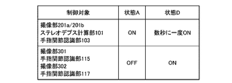
- the activation control unit 123 of the information processing apparatus 10 is located between the first operation unit and the second operation unit related to finger recognition based on the detection result of the wearable device 30. Controls the switching of the operating unit activated in. According to such a configuration, it is possible to robustly recognize the fingers while reducing the power consumption required for the recognition of the fingers.
- the activation control unit 123 also controls activation of a third operation unit related to finger recognition. In the following, controlling the operation unit to be activated may be expressed as "turning on”, and controlling the operation unit to be stopped may be expressed as "turning off”.
- the first moving unit includes a first sensor that obtains the first data (depth image) in which the finger is recognized, and a first recognition unit that recognizes the finger based on the first data. It is mainly assumed that both are included. However, the first moving unit may include at least one of such a first sensor and a first recognition unit. In the following description, it is mainly assumed that the image pickup units 201a and 201b are used as an example of the first sensor. However, as the first sensor, as described above, a sensor that substitutes for the image pickup units 201a and 201b may be used. Further, in the following description, the finger joint recognition unit 103 is used as an example of the first recognition unit.
- the second moving unit recognizes the finger based on the second sensor for obtaining the second data (depth image) on which the finger is recognized and the second recognition based on the second data. It is mainly assumed that both parts and parts are included. However, the second moving unit may include at least one of such a second sensor and a second recognition unit. In the following description, it is mainly assumed that the image pickup unit (palm side) 301 is used as an example of the second sensor. However, as the second sensor, a sensor that substitutes for the image pickup unit (palm side) 301 may be used. Further, in the following description, the finger joint recognition unit 115 is used as an example of the second recognition unit.
- the third moving unit has a third sensor that obtains a third data (depth image) in which the finger is recognized, and a third recognition unit that recognizes the finger based on the third data. It is mainly assumed that both of and are included. However, the third moving unit may include at least one of such a third sensor and a third recognition unit. In the following description, it is mainly assumed that the imaging unit (back side of the hand) 302 is used as an example of the third sensor. However, as the third sensor, a sensor that substitutes for the image pickup unit (back side of the hand) 302 may be used. Further, in the following description, the finger joint recognition unit 117 is used as an example of the third recognition unit.
- the user's fingers will be described as an example of the recognition target existing in the real space.
- a wearable device 30 (particularly, an optical marker 320) worn on a hand as a detection target will be described as an example.
- the recognition target does not have to be a finger, and the detection target does not have to be the wearable device 30.
- the recognition target may be a body part other than the fingers (for example, the user's arm or palm).
- the detection target may be one whose position changes with the change of the position of the recognition target.
- the recognition target and the detection target are not limited to different ones, and may be the same (for example, the recognition target and the detection target may both be fingers).
- the imaging unit 301 (as an example of the second sensor) is attached to the user's body at a position closer to the recognition target than the imaging units 201a and 201b (as an example of the first sensor).
- the image pickup unit 301 is less likely to cause self-occlusion than the image pickup units 201a and 201b, and the recognition target can be recognized with high reliability. Therefore, it is expected that the effect enjoyed by switching the activated sensor (or recognition unit) will be increased.
- the imaging unit 302 (as an example of the third sensor) be attached to the user's body closer to the recognition target than the imaging units 201a and 201b (as an example of the first sensor). ..
- imaging units 201a and 201b are mounted on the head (as an example of a first site) and as an example of a second sensor.
- the imaging unit 301 is attached to a predetermined portion (particularly on the palm side) of the upper limb (as an example of a second region different from the first region), and the imaging unit (as an example of the third sensor).
- the 302 is attached to a predetermined part of the upper limb (particularly on the back side of the hand) (as an example of a third part different from the first part), and the recognition target is the end of the upper limb from the predetermined part.
- the upper limb portion may mean a portion of the user's body beyond the shoulder (for example, somewhere in the arm, hand, or finger).
- the activation control unit 123 controls switching of the operation unit to be activated based on the detection result of the wearable device 30 (as an example of the detection target).
- the detection result of the wearable device 30 detected by the wearable device position / attitude integration unit 113 based on the data (imaging result) obtained by the IR imaging unit 201d of the input / output device 20 is used by the activation control unit 123. It is mainly assumed that the case is possible. More specifically, the orientation of the IR imaging unit 201d changes with the orientation of the input / output devices 20 (imaging units 201a and 201b).
- the position of the wearable device 30 based on the data obtained by the IR imaging unit 201d is a position detected by the wearable device position / attitude integration unit 113 as a relative position of the wearable device 30 with respect to the position of the input / output device 20. Is detected as.
- the method for detecting the wearable device 30 is not limited to such an example.
- the detection result of the wearable device 30 detected by the wearable device position / attitude integration unit 113 may be used by the activation control unit 123 based on the data obtained by the inertial measurement unit 303 of the wearable device 30. More specifically, the inertia of the wearable device 30 (calculated by the inertial integral calculation unit 121 based on the data obtained by the inertial measurement unit 220 of the input / output unit 20) with respect to the position of the input / output unit 20. The relative position of the wearable device 30 (calculated by the inertial integral calculation unit 111 based on the data obtained by the measurement unit 303) may be detected as a detection position by the wearable device position / attitude integration unit 113.
- the detection result of the wearable device 30 detected based on the data obtained by the magnetic sensor may be used by the activation control unit 123. More specifically, when the wearable device 30 is provided with a device (for example, a magnet) that generates a magnetic field, and the input / output device 20 is provided with a magnetic sensor (for example, a detection coil) that detects the magnetic flux. , The direction of arrival of the magnetic field detected by the magnetic sensor (that is, the direction in which the wearable device 30 exists with respect to the position of the input / output device 20) may be detected as the detection position.
- a device for example, a magnet
- a magnetic sensor for example, a detection coil
- the detection result of the wearable device 30 detected based on the data obtained by the ultrasonic sensor may be used by the activation control unit 123. More specifically, when the wearable device 30 is provided with a device for generating ultrasonic waves and the input / output device 20 is provided with an ultrasonic sensor for detecting the ultrasonic waves, the ultrasonic waves detected by the ultrasonic sensors are provided. The arrival direction of the wearable device 30 (that is, the direction in which the wearable device 30 is present with respect to the position of the input / output device 20) may be detected as the detection position.
- FIG. 10 is a diagram showing an example of the angle of view of the IR image pickup unit 201d of the input / output device 20. With reference to FIG. 10, the angle of view 1201 (FoV) of the IR imaging unit 201d is shown.
- the activation control unit 123 controls switching of the operation unit to be activated based on the detection result of the wearable device 30. More specifically, the activation control unit 123 controls switching of the operation unit to be activated based on the positional relationship between the angle of view 1201 of the IR imaging unit 201d and the detection position of the wearable device 30.
- the area outside the angle of view 1201 is the outside area E3.
- a region with reference to the center of the angle of view 1201 (hereinafter, also referred to as “central region E1”) is shown, and the inside of the outer region E3 is shown.
- a region and a region outside the central region E1 (hereinafter, also referred to as “buffer region E2”) are shown. Further, the boundary 1202 between the central region E1 and the buffer region E2 is shown. In the example shown in FIG.
- the horizontal angle of view of the angle of view 1201 is 100 degrees
- the vertical angle of view of the angle of view 1201 is 80 degrees
- the horizontal angle of view of the boundary 1202 is 75 degrees
- the vertical angle of view 1202 is vertical.
- the angle of view is 60 degrees.
- the specific values of these horizontal and vertical angles of view are not limited.
- the internal region of the angle of view 1201 (that is, the central region E1 and the buffer region E2) is an example of a region (first region) corresponding to the orientation of the portion (head) to which the input / output device 20 is mounted. be. Therefore, instead of the internal region of the angle of view 1201, another region according to the orientation of the portion (head) to which the input / output device 20 is mounted (for example, a partial region set in the internal region of the angle of view 1201). Region) may be used.
- the area inside the angle of view 1201 is a rectangular area, but the shape of the area used in place of the area inside the angle of view 1201 does not necessarily have to be a rectangular area. good.
- the central region E1 is an example of a region (second region) according to the orientation of the portion (head) where the input / output device 20 is mounted. Therefore, instead of the central region E1, another region depending on the orientation of the portion (head) on which the input / output device 20 is mounted may be used.
- the central region E1 is a rectangular region, but the shape of the region used in place of the central region E1 does not necessarily have to be a rectangular region.
- the center of the boundary 1202 and the center of the angle of view 1201 coincide with each other. However, as will be described later, the center of the boundary 1202 and the center of the angle of view 1201 do not have to coincide with each other.
- the activation control unit 123 determines that the detection position of the wearable device 30 is within the central region E1.
- the activation control unit 123 turns on the image pickup units 201a and 201b of the input / output device 20, the stereo depth calculation unit 101, and the finger joint recognition unit 103 (starts power supply), and at the same time, the wearable device 30.
- the imaging units 301 and 302 and the finger joint recognition units 115 and 117 are turned off (power supply is stopped).
- the IR image pickup unit 201d of the input / output device 20 is always turned on regardless of such control (because it is used for detecting the wearable device 30).
- the activation control unit 123 determines that the detection position of the wearable device 30 is within the outer region E3. In such a case, the activation control unit 123 turns off the image pickup units 201a and 201b of the input / output device 20, the stereo depth calculation unit 101, and the finger joint recognition unit 103 (stops the power supply), and at the same time, the wearable device 30. The imaging units 301 and 302 and the finger joint recognition units 115 and 117 are turned on (power supply is started). It is also assumed that the image pickup units 201a and 201b of the input / output device 20 are used for applications other than finger joint recognition (for example, SLAM). In such a case, the activation control unit 123 may turn off only the stereo depth calculation unit 101 and the finger joint recognition unit 103 without turning off the image pickup units 201a and 201b.
- SLAM finger joint recognition
- the activation control unit 123 determines that the detection position of the wearable device 30 is in the buffer area E2.
- the activation control unit 123 includes the image pickup units 201a and 201b of the input / output device 20, the stereo depth calculation unit 101 and the finger joint recognition unit 103, the image pickup units 301 and 302 of the wearable device 30, and the finger joint recognition unit 115. Turn 117 on.
- the other imaging unit is imaged before the imaging unit is turned off. It is possible to prevent a period in which data (imaging result) cannot be obtained from the imaging units 201a and 201b of the input / output device 20 and from the imaging units 301 and 302 of the wearable device 30. It will be possible.
- the buffer area E2 (third area) is provided, but it can be assumed that the buffer area E2 is not provided.
- the angle of view 1201 and the boundary 1202 need not be particularly distinguished (for example, when the detection position of the wearable device 30 is in the buffer area E2, the detection position of the wearable device 30 is in the central area E1. It should be treated in the same way as in some cases).
- FIG. 11 is a diagram in which the basic control by the activation control unit 123 is arranged for each state.
- "state A” indicates a state in which the detection position of the wearable device 30 is determined to be in the central region E1 (FIG. 10).
- the imaging units 201a and 201b, the stereo depth calculation unit 101 and the finger joint recognition unit 103 are ON, and the imaging units 301 and 302 and the finger joint recognition units 115 and 117 are OFF.
- state B indicates a state in which the detection position of the wearable device 30 is determined to be in the outer region E3 (FIG. 10).
- the imaging units 201a and 201b, the stereo depth calculation unit 101 and the finger joint recognition unit 103 are OFF, and the imaging units 301 and 302 and the finger joint recognition units 115 and 117 are ON.
- state C indicates a case where it is determined that the detection position of the wearable device 30 is in the buffer area E2 (FIG. 10).
- the imaging units 201a and 201b, the stereo depth calculation unit 101, the finger joint recognition unit 103, the imaging units 301 and 302, and the finger joint recognition units 115 and 117 are ON.
- the initial state is assumed to be "state A”.
- the activation control unit 123 detects that the detection position of the wearable device 30 is in the outer region E3. In such a case, the activation control unit 123 shifts the current state from "state A” to "state B” based on such detection. On the other hand, it is assumed that the activation control unit 123 detects that the detection position of the wearable device 30 is in the buffer area E2 when the current state is the “state A”. In such a case, the activation control unit 123 shifts the current state from "state A" to "state C" based on such detection.
- the activation control unit 123 detects that the detection position of the wearable device 30 has moved to the central region E1 when the current state is "state B". In such a case, the activation control unit 123 shifts the current state from "state B” to "state A” based on the movement. On the other hand, it is assumed that the activation control unit 123 detects that the detection position of the wearable device 30 has moved to the buffer area E2 when the current state is the “state B”. In such a case, the activation control unit 123 shifts the current state from "state A” to "state C” based on the movement.
- the activation control unit 123 detects that the detection position of the wearable device 30 has moved to the central region E1 when the current state is "state C". In such a case, the activation control unit 123 shifts the current state from "state C" to "state A” based on the movement. On the other hand, it is assumed that the activation control unit 123 detects that the detection position of the wearable device 30 has moved to the outer region E3 when the current state is the “state C”. In such a case, the activation control unit 123 shifts the current state from "state C" to "state B" based on the movement.
- the activation control unit 123 turns on the imaging units 201a and 201b, the stereo depth calculation unit 101, and the finger joint recognition unit 103. At the same time, the imaging units 301 and 302 and the finger joint recognition units 115 and 117 are turned off.
- the activation control unit 123 turns off the imaging units 201a and 201b, the stereo depth calculation unit 101 and the finger joint recognition unit 103, and the imaging units 301 and 302. , Turn on the finger joint recognition units 115 and 117. This makes it possible to robustly recognize the finger joint position while reducing the power consumption required for recognizing the finger joint position.
- the position of the boundary 1202 may be variable.
- the activation control unit 123 may adjust the position of the boundary 1202 based on the relative speed (viewed from the image pickup unit 201) of the wearable device 30. As an example, when the relative speed of the wearable device 30 with respect to the image pickup unit 201 is larger than the first speed, the activation control unit 123 sets the boundary 1202 at the center of the angle of view 1201 (because the buffer area E2 should be large). You may bring them closer. On the other hand, when the relative speed of the wearable device 30 with respect to the image pickup unit 201 is smaller than the second speed, the activation control unit 123 moves the boundary 1202 away from the center of the angle of view 1201 (because the buffer region E2 may be small). You may.
- the activation control unit 123 uses the position (predicted position) predicted based on the detection position instead of the detection position of the wearable device 30. You may.
- the activation control unit 123 may perform after a certain period of time (for example, 16.6 milliseconds) has elapsed based on the detection position of the wearable device 30 and the relative speed of the wearable device 30 (as viewed from the image pickup unit 201).
- the position of the wearable device 30 may be predicted, and the predicted position (predicted position) may be used instead of the detection position of the wearable device 30.
- the relative position / posture R2 (viewed from the image pickup unit 201) of the wearable device 30 is the first. It is also assumed that the condition is satisfied (for example, the angle formed by the surface of the controller unit 31 to which the optical marker 320 is attached and the orientation of the image pickup unit 201 is smaller than the first angle). In such a case, it is assumed that the user's fingers are difficult to be recognized accurately based on the data obtained by the imaging units 201a and 201b.
- the activation control unit 123 may be in a position where the reliability of the finger joint position recognized by the finger joint recognition unit 103 is lower than the first threshold value, or the relative position / posture of the wearable device 30 (as viewed from the image pickup unit 201).
- R2 FIG. 4
- the stereo depth calculation unit 101 and the finger joint recognition unit 103 are turned off, and the image pickup unit 301 of the wearable device 30. Turn on 302 and the finger joint recognition units 115 and 117.
- the image pickup units 201a and 201b of the input / output device 20 are used for applications other than finger joint recognition (for example, SLAM).
- the activation control unit 123 may turn off only the stereo depth calculation unit 101 and the finger joint recognition unit 103 without turning off the image pickup units 201a and 201b.
- the activation control unit 123 turns on the image pickup units 201a and 201b, the stereo depth calculation unit 101, and the finger joint recognition unit 103 of the input / output device 20 at predetermined time intervals (for example, once every few seconds). As a result, the activation control unit 123 acquires the reliability of the finger joint position recognized by the finger joint recognition unit 103 based on the data obtained by the image pickup units 201a and 201b of the input / output device 20.
- the activation control unit 123 may be used when the reliability of the finger joint position recognized by the finger joint recognition unit 103 exceeds the second threshold value, or when the wearable device 30 has a relative position / posture R2 (as viewed from the image pickup unit 201).
- FIG. 4 satisfies the second condition (for example, when the angle formed by the surface of the controller unit 31 to which the optical marker 320 is attached and the orientation of the image pickup unit 201 is larger than the second angle), the input / output device. While the image pickup units 201a and 201b, the stereo depth calculation unit 101 and the finger joint recognition unit 103 of the wearable device 20 are kept ON, the image pickup units 301 and 302 and the finger joint recognition units 115 and 117 of the wearable device 30 are turned off.
- the activation control unit 123 is a position where the reliability of the finger joint position recognized by the finger joint recognition unit 103 is equal to or less than the second threshold value and the relative position (as viewed from the image pickup unit 201) of the wearable device 30.
- the posture R2 (FIG. 4) does not satisfy the second condition, the image pickup units 201a and 201b of the input / output device 20, the stereo depth calculation unit 101, and the finger joint recognition unit 103 are turned off again.
- the first threshold value and the second threshold value may be the same or different.
- the first angle and the second angle may be the same or different.
- FIG. 12 is a diagram in which the control by the reliability by the activation control unit 123 is arranged for each state.
- each of "state A" and “state D” indicates a state in which the detection position of the wearable device 30 is determined to be in the central region E1 (FIG. 10).
- the imaging units 201a and 201b, the stereo depth calculation unit 101 and the finger joint recognition unit 103 are ON, and the imaging units 301 and 302 and the finger joint recognition units 115 and 117 are OFF.
- the image pickup units 201a and 201b, the stereo depth calculation unit 101 and the finger joint recognition unit 103 are OFF, and the image pickup units 301 and 302 and the finger joint recognition units 115 and 117 are ON.
- the image pickup units 201a and 201b, the stereo depth calculation unit 101, and the finger joint recognition unit 103 of the input / output device 20 are turned on at the time intervals of (for example, once every few seconds).
- the activation control unit 123 When the reliability of the finger joint position recognized by the finger joint recognition unit 103 is lower than the first threshold value when the current state is "state A", the activation control unit 123, or the wearable device 30 ( It is assumed that it is determined that the relative position / posture R2 (FIG. 4) (viewed from the image pickup unit 201) satisfies the first condition. In such a case, the activation control unit 123 shifts the current state from "state A" to "state D".
- the activation control unit 123 when the activation control unit 123 is in the "state D" and the reliability of the finger joint position recognized by the finger joint recognition unit 103 exceeds the second threshold value, or the wearable device 30 It is assumed that it is determined that the relative position / posture R2 (FIG. 4) (viewed from the image pickup unit 201) satisfies the second condition. In such a case, the activation control unit 123 shifts the current state from "state D" to "state A".
- the reliability of the finger joint position recognized by the finger joint recognition unit 103 based on the data obtained by the image pickup unit 301 of the wearable device 30 exceeds the fourth threshold value.
- the image pickup unit 302 of the wearable device 30 may be turned off. This makes it possible to suppress a decrease in the recognition accuracy of the finger joint position while reducing the power consumption required for recognizing the finger joint position.
- the activation control unit 123 determines that the detection position of the wearable device 30 is within the outer region E3. In such a case, the activation control unit 123 turns off the image pickup units 201a and 201b of the input / output device 20, the stereo depth calculation unit 101, and the finger joint recognition unit 103 (stops the power supply), and at the same time, the wearable device 30. Turn on the image pickup unit 301 and the finger joint recognition unit 115 (start power supply). However, the activation control unit 123 temporarily turns off the image pickup unit 302 and the finger joint recognition unit 117 of the wearable device 30.
- the image pickup units 201a and 201b of the input / output device 20 are used for applications other than finger joint recognition (for example, SLAM).
- the activation control unit 123 may turn off only the stereo depth calculation unit 101 and the finger joint recognition unit 103 without turning off the image pickup units 201a and 201b.
- the activation control unit 123 acquires the reliability of the finger joint position recognized by the finger joint recognition unit 115 based on the data obtained by the image pickup unit 301 of the wearable device 30.
- the activation control unit 123 is a wearable device 30 when the imaging unit 302 and the finger joint recognition unit 117 are OFF, and when the reliability of the finger joint position recognized by the finger joint recognition unit 115 is lower than the third threshold value.
- the imaging unit 302 and the finger joint recognition unit 117 of the above are turned on.
- the activation control unit 123 is wearable when the imaging unit 302 and the finger joint recognition unit 117 are ON and the reliability of the finger joint position recognized by the finger joint recognition unit 115 exceeds the fourth threshold value.
- the imaging unit 302 and the finger joint recognition unit 117 of the device 30 are turned off.
- the third threshold value and the fourth threshold value may be the same or different. Further, there may be downtime for switching between ON and OFF of the image pickup unit 302 and the finger joint recognition unit 117 of the wearable device 30. That is, when the activation control unit 123 switches the imaging unit 302 and the finger joint recognition unit 117 of the wearable device 30 from ON to OFF, the finger joint position recognized by the finger joint recognition unit 115 until a certain period of time elapses. Regardless of the reliability, the image pickup unit 302 and the finger joint recognition unit 117 of the wearable device 30 may not be switched on again.
- the activation control unit 123 determines that the detection position of the wearable device 30 is in the buffer area E2.
- the activation control unit 123 includes the image pickup units 201a and 201b of the input / output device 20, the stereo depth calculation unit 101 and the finger joint recognition unit 103, the image pickup units 301 and 302 of the wearable device 30, and the finger joint recognition unit 115. Turn 117 on. As described above, it is possible to prevent a period in which data (imaging result) cannot be obtained from the imaging units 201a and 201b of the input / output device 20 and from the imaging units 301 and 302 of the wearable device 30. It will be possible.
- the activation control unit 123 turns off the image pickup units 201a and 201b of the input / output device 20, the stereo depth calculation unit 101, and the finger joint recognition unit 103. (Stop the power supply) and turn on the image pickup unit 301 and the finger joint recognition unit 115 of the wearable device 30 (start the power supply). However, the activation control unit 123 temporarily turns off the image pickup unit 302 and the finger joint recognition unit 117 of the wearable device 30.
- the image pickup units 201a and 201b of the input / output device 20 are used for applications other than finger joint recognition (for example, SLAM).
- the activation control unit 123 may turn off only the stereo depth calculation unit 101 and the finger joint recognition unit 103 without turning off the image pickup units 201a and 201b.
- the activation control unit 123 recognizes when the imaging unit 302 and the finger joint recognition unit 117 are OFF and by the finger joint recognition unit 115, as in the case where the detection position of the wearable device 30 is in the outer region E3.
- the image pickup unit 302 and the finger joint recognition unit 117 of the wearable device 30 are turned on.
- the activation control unit 123 is wearable when the imaging unit 302 and the finger joint recognition unit 117 are ON and the reliability of the finger joint position recognized by the finger joint recognition unit 115 exceeds the fourth threshold value.
- the imaging unit 302 and the finger joint recognition unit 117 of the device 30 are turned off.
- FIG. 13 is a diagram in which the control by the reliability of the wearable device side by the activation control unit 123 is arranged for each state.
- state A indicates a state in which the detection position of the wearable device 30 is determined to be in the central region E1 (FIG. 10).
- state B1 indicates a state in which the detection position of the wearable device 30 is determined to be in the outer region E3 (FIG. 10).
- state C1 and “state C2” indicate a state in which the detection position of the wearable device 30 is determined to be in the buffer area E2 (FIG. 10).
- the imaging units 201a and 201b, the stereo depth calculation unit 101 and the finger joint recognition unit 103 are ON, and the imaging units 301 and 302 and the finger joint recognition units 115 and 117 are OFF.
- the image pickup unit 201a, 201b, the stereo depth calculation unit 101, and the finger joint recognition unit 103 are OFF, and the image pickup unit 301 and the finger joint recognition unit 115 are ON, but the image pickup unit 302 and the finger joint recognition unit are ON.
- the unit 117 is OFF.
- the imaging unit 201a and 201b, the stereo depth calculation unit 101 and the finger joint recognition unit 103 are OFF, the imaging unit 301 and the finger joint recognition unit 115 are ON, and the image pickup unit 302 and the finger joint recognition unit are ON. 117 is also ON.
- the image pickup unit 201a, 201b, the stereo depth calculation unit 101, and the finger joint recognition unit 103 are ON, and the image pickup unit 301 and the finger joint recognition unit 115 are ON, but the image pickup unit 302 and the finger joint recognition unit are ON.
- the unit 117 is OFF.
- the imaging unit 201a and 201b, the stereo depth calculation unit 101 and the finger joint recognition unit 103 are ON, the imaging unit 301 and the finger joint recognition unit 115 are ON, and the image pickup unit 302 and the finger joint recognition unit are ON. 117 is also ON.
- the initial state is assumed to be "state A".
- the activation control unit 123 determines that the detection position of the wearable device 30 is in the outer region E3 when the current state is "state A”. In such a case, the activation control unit 123 shifts the current state from "state A” to "state B1". On the other hand, it is assumed that the activation control unit 123 determines that the detection position of the wearable device 30 is in the buffer area E2 when the current state is the “state A”. In such a case, the activation control unit 123 shifts the current state from "state A" to "state C1".
- the activation control unit 123 changes the current state to the "state”. Transition from “B1" to "state B2". On the other hand, when the current state is "state B2", the activation control unit 123 changes the current state when the reliability of the finger joint position recognized by the finger joint recognition unit 115 exceeds the fourth threshold value. Transition from "state B2" to "state B1".
- the activation control unit 123 is in the current state when the reliability of the finger joint position recognized by the finger joint recognition unit 115 falls below the third threshold value. Is changed from “state C1" to "state C2".
- the activation control unit 123 changes the current state when the reliability of the finger joint position recognized by the finger joint recognition unit 115 exceeds the fourth threshold value. The transition is made from “state C2" to "state C1".
- the activation control unit 123 detects that the detection position of the wearable device 30 has moved to the central region E1 when the current state is “state B1” or “state B2". In such a case, the activation control unit 123 shifts the current state from “state B1” or “state B2” to "state A”. On the other hand, it is assumed that the activation control unit 123 detects that the detection position of the wearable device 30 has moved to the buffer area E2 when the current state is “state B1” or “state B2”. In such a case, the activation control unit 123 shifts the current state from "state B1” or “state B2” to "state C1".
- the activation control unit 123 detects that the detection position of the wearable device 30 has moved to the central region E1 when the current state is “state C1" or “state C2". In such a case, the activation control unit 123 shifts the current state from “state C1” or “state C2” to "state A”. On the other hand, it is assumed that the activation control unit 123 detects that the detection position of the wearable device 30 has moved to the outer region E3 when the current state is “state C1” or “state C2”. In such a case, the activation control unit 123 shifts the current state from "state C1” or “state C2" to "state B1".
- FIG. 14 is a diagram in which an example in which control based on the reliability of the input / output device side and control based on the reliability of the wearable device side are integrated is organized by state.
- the control by the reliability of the input / output device shown in FIG. 12 is organized by state
- the control by the reliability of the wearable device shown in FIG. 13 is organized by state.
- This is an example in which the "state D" is also separated into the “state D1" and the "state D2" after integrating the figures arranged in.
- the initial state is assumed to be "state A".
- the activation control unit 123 determines that the reliability of the finger joint position recognized by the finger joint recognition unit 103 is below the first threshold value, or the wearable device 30 ( It is assumed that it is determined that the relative position / orientation (FIG. 4) as seen from the image pickup unit 201) satisfies the first condition. In such a case, the activation control unit 123 shifts the current state from "state A" to "state D1".
- the activation control unit 123 determines that the reliability of the finger joint position recognized by the finger joint recognition unit 103 exceeds the second threshold value, or the wearable device 30 ( It is assumed that it is determined that the relative position / posture R2 (FIG. 4) (viewed from the image pickup unit 201) satisfies the second condition. In such a case, the activation control unit 123 shifts the current state from "state D1" to "state A”. When the current state is the "state D1" and the reliability of the finger joint position recognized by the finger joint recognition unit 115 is lower than the third threshold value, the activation control unit 123 changes the current state to the "state”. Transition from "D1" to "state D2".
- the activation control unit 123 determines that the reliability of the finger joint position recognized by the finger joint recognition unit 103 exceeds the second threshold value, or the wearable device 30 ( It is assumed that it is determined that the relative position / posture R2 (FIG. 4) (viewed from the image pickup unit 201) satisfies the second condition. In such a case, the activation control unit 123 shifts the current state from "state D2" to "state A”. When the current state is the "state D2" and the reliability of the finger joint position recognized by the finger joint recognition unit 115 exceeds the fourth threshold value, the activation control unit 123 changes the current state to the "state”. Transition from "D2" to "state D1".
- the activation control unit 123 determines that the detection position of the wearable device 30 is in the outer region E3 when the current state is "state A”, “state D1", or “state D2". In such a case, the activation control unit 123 shifts the current state to the "state B1". On the other hand, it is assumed that the activation control unit 123 determines that the detection position of the wearable device 30 is in the buffer area E2 when the current state is "state A”, “state D1", or “state D2". In such a case, the activation control unit 123 shifts the current state to the "state C1".
- the activation control unit 123 When the activation control unit 123 is in the "state B1" and the reliability of the finger joint position recognized by the finger joint recognition unit 115 is lower than the third threshold value, the activation control unit 123 changes the current state to the "state”. Transition from “B1" to "state B2". When the activation control unit 123 changes the current state to the "state” when the reliability of the finger joint position recognized by the finger joint recognition unit 115 exceeds the fourth threshold value when the current state is the "state B2". Transition from "B2" to "state B1".
- the activation control unit 123 determines that the detection position of the wearable device 30 is in the central region E1 when the current state is "state B1" or “state B2". In such a case, the activation control unit 123 shifts the current state to the "state A”. On the other hand, it is assumed that the activation control unit 123 determines that the detection position of the wearable device 30 is in the buffer area E2 when the current state is "state B1" or "state B2". In such a case, the activation control unit 123 shifts the current state to the "state C1".
- the activation control unit 123 When the activation control unit 123 is in the "state C1" and the reliability of the finger joint position recognized by the finger joint recognition unit 115 is lower than the third threshold value, the activation control unit 123 changes the current state to the "state”. Transition from “C1” to "state C2". When the activation control unit 123 changes the current state to the "state” when the reliability of the finger joint position recognized by the finger joint recognition unit 115 exceeds the fourth threshold value when the current state is the "state C2". Transition from "C2" to "state C1".
- the activation control unit 123 determines that the detection position of the wearable device 30 is in the central region E1 when the current state is "state C1" or “state C2". In such a case, the activation control unit 123 shifts the current state to the "state A”. On the other hand, it is assumed that the activation control unit 123 determines that the detection position of the wearable device 30 is in the outer region E3 when the current state is "state C1" or "state C2". In such a case, the activation control unit 123 shifts the current state to the "state B1".
- FIG. 15 is a functional block diagram showing a configuration example of a hardware configuration of various information processing devices constituting the information processing system 1 according to the embodiment of the present disclosure.
- the information processing apparatus 900 constituting the information processing system 1 mainly includes a CPU (Central Processing unit) 901, a ROM (Read Only Memory) 902, and a RAM (Random Access Memory) 903. .
- the information processing device 900 further includes a host bus 907, a bridge 909, an external bus 911, an interface 913, an input device 915, an output device 917, a storage device 919, a drive 921, and a connection port 923. And a communication device 925.
- the CPU 901 functions as an arithmetic processing device and a control device, and controls all or a part of the operation in the information processing device 900 according to various programs recorded in the ROM 902, the RAM 903, the storage device 919, or the removable recording medium 927.
- the ROM 902 stores programs, calculation parameters, and the like used by the CPU 901.
- the RAM 903 primary stores a program used by the CPU 901, parameters that change as appropriate in the execution of the program, and the like. These are connected to each other by a host bus 907 composed of an internal bus such as a CPU bus.
- a host bus 907 composed of an internal bus such as a CPU bus.
- each block of the information processing apparatus 10 shown in FIG. 5 may be configured by the CPU 901.
- the host bus 907 is connected to an external bus 911 such as a PCI (Peripheral Component Interconnect / Interface) bus via a bridge 909. Further, an input device 915, an output device 917, a storage device 919, a drive 921, a connection port 923, and a communication device 925 are connected to the external bus 911 via the interface 913.
- an external bus 911 such as a PCI (Peripheral Component Interconnect / Interface) bus
- an input device 915, an output device 917, a storage device 919, a drive 921, a connection port 923, and a communication device 925 are connected to the external bus 911 via the interface 913.
- the input device 915 is an operation means operated by the user, such as a mouse, a keyboard, a touch panel, a button, a switch, a lever, and a pedal. Further, the input device 915 may be, for example, a remote control means (so-called remote controller) using infrared rays or other radio waves, or an external connection device such as a mobile phone or a PDA corresponding to the operation of the information processing device 900. It may be 929. Further, the input device 915 is composed of, for example, an input control circuit that generates an input signal based on the information input by the user using the above-mentioned operating means and outputs the input signal to the CPU 901. By operating the input device 915, the user of the information processing apparatus 900 can input various data to the information processing apparatus 900 and instruct the processing operation.
- a remote control means such as a mobile phone or a PDA corresponding to the operation of the information processing device 900. It may be 929.
- the input device 915 is composed
- the output device 917 is composed of a device capable of visually or audibly notifying the user of the acquired information.
- Such devices include display devices such as CRT display devices, liquid crystal display devices, plasma display devices, EL display devices and lamps, audio output devices such as speakers and headphones, and printer devices.
- the output device 917 outputs, for example, the results obtained by various processes performed by the information processing device 900.
- the display device displays the results obtained by various processes performed by the information processing device 900 as text or an image.
- the audio output device converts an audio signal composed of reproduced audio data, acoustic data, and the like into an analog signal and outputs the signal.
- the output unit 210 shown in FIG. 5 may be configured by an output device 917.
- the storage device 919 is a data storage device configured as an example of the storage unit of the information processing device 900.
- the storage device 919 is composed of, for example, a magnetic storage device such as an HDD (Hard Disk Drive), a semiconductor storage device, an optical storage device, an optical magnetic storage device, or the like.
- the storage device 919 stores programs executed by the CPU 901, various data, and the like.
- the storage unit 190 shown in FIG. 5 may be configured by a storage device 919.
- the drive 921 is a reader / writer for a recording medium, and is built in or externally attached to the information processing apparatus 900.
- the drive 921 reads the information recorded on the removable recording medium 927 such as a mounted magnetic disk, optical disk, magneto-optical disk, or semiconductor memory, and outputs the information to the RAM 903.
- the drive 921 can also write a record to a removable recording medium 927 such as a mounted magnetic disk, optical disk, magneto-optical disk, or semiconductor memory.
- the removable recording medium 927 is, for example, a DVD media, an HD-DVD media, a Blu-ray (registered trademark) medium, or the like.
- the removable recording medium 927 may be a compact flash (registered trademark) (CF: CompactFlash), a flash memory, an SD memory card (Secure Digital memory card), or the like. Further, the removable recording medium 927 may be, for example, an IC card (Integrated Circuit card) or an electronic device equipped with a non-contact type IC chip.
- CF CompactFlash
- SD memory card Secure Digital memory card
- the connection port 923 is a port for directly connecting to the information processing device 900.
- the connection port 923 there are a USB (Universal Serial Bus) port, an IEEE1394 port, a SCSI (Small Computer System Interface) port, and the like.
- the connection port 923 there are an RS-232C port, an optical audio terminal, an HDMI (registered trademark) (High-Definition Multidimedia Interface) port, and the like.
- the communication device 925 is, for example, a communication interface composed of a communication device or the like for connecting to a communication network (network) 931.
- the communication device 925 is, for example, a communication card for a wired or wireless LAN (Local Area Network), Bluetooth (registered trademark), WUSB (Wireless USB), or the like.
- the communication device 925 may be a router for optical communication, a router for ADSL (Asymmetric Digital Subscriber Line), a modem for various communications, or the like.
- the communication device 925 can transmit and receive signals and the like to and from the Internet and other communication devices in accordance with a predetermined protocol such as TCP / IP.
- the communication network 931 connected to the communication device 925 is configured by a network or the like connected by wire or wirelessly, and may be, for example, the Internet, a home LAN, infrared communication, radio wave communication, satellite communication, or the like. ..
- the above is an example of a hardware configuration capable of realizing the functions of the information processing apparatus 900 constituting the information processing system 1 according to the embodiment of the present disclosure.
- Each of the above-mentioned components may be configured by using general-purpose members, or may be configured by hardware specialized for the function of each component. Therefore, it is possible to appropriately change the hardware configuration to be used according to the technical level at the time of implementing the present embodiment.
- various configurations corresponding to the information processing apparatus 900 constituting the information processing system 1 are naturally provided.
- the recording medium is, for example, a magnetic disk, an optical disk, a magneto-optical disk, a flash memory, or the like.
- the computer program described above may be distributed via a network, for example, without using a recording medium.
- the number of computers for executing the computer program is not particularly limited. For example, a plurality of computers (for example, a plurality of servers, etc.) may execute the computer program in cooperation with each other.
- the operation unit activated between the first operation unit and the second operation unit related to the recognition of the recognition target existing in the real space.
- the first sensor which comprises a control unit for controlling the switching of the above and obtains the first data in which the recognition target is recognized, is attached to the first part of the user's body and the recognition target is recognized.
- the second sensor for obtaining the data of the above is provided with an information processing apparatus attached to a second part of the body different from the first part.
- the following configurations also belong to the technical scope of the present disclosure.
- a control unit that controls switching of the operation unit activated between the first operation unit and the second operation unit related to the recognition of the recognition target existing in the real space.
- the first sensor for obtaining the first data in which the recognition target is recognized is attached to the first part of the user's body, and the second sensor for obtaining the second data in which the recognition target is recognized is a second sensor. Attached to a second part of the body that is different from the first part.
- Information processing equipment (2)
- the first operating unit includes at least one of the first sensor and the first recognition unit that recognizes the recognition target based on the first data.
- the second operating unit includes at least one of the second sensor and the second recognition unit that recognizes the recognition target based on the second data.
- the control unit is a second region corresponding to the orientation of the first portion from outside the first region of the detection position of the detection target or the predicted position based on the detection position according to the orientation of the first portion. Control so that the second moving unit is stopped based on the movement of the second moving unit into the region.
- the control unit controls the first moving unit to be activated based on the movement of the detected position or the predicted position from outside the first region to the inside of the second region.
- the control unit is based on the movement of the detection position or the prediction position from outside the first region to into a third region, which is a region outside the second region of the first region.
- the information processing apparatus according to (3) above.
- the control unit controls the first moving unit to be stopped based on the movement of the detection position or the predicted position from the inside of the second region to the outside of the first region.
- the control unit controls the second operation unit to be activated based on the movement of the detection position or the predicted position from the inside of the second region to the outside of the first region.
- the control unit is based on the movement of the detection position or the prediction position from the inside of the second region to the third region of the first region, which is an outer region of the second region. Then, the second moving unit is controlled to be activated.
- the information processing apparatus according to (6) above.
- the control unit when the reliability of recognition of the recognition target by the recognition unit is lower than the first threshold value, or when the relative position / orientation with respect to the first sensor of the detection target is first. When the condition is satisfied, the second operating unit is controlled to be activated.
- the information processing device according to (2) above.
- the second moving unit When the relative position / orientation with respect to the first sensor satisfies the second condition, the second moving unit is controlled to be stopped.
- the information processing apparatus according to (9) above.
- the control unit may recognize the detection target by the second recognition unit.
- the third moving unit When the reliability of the recognition of the object is lower than the third threshold value, the third moving unit is controlled to be activated.
- the information processing device according to (2) above.
- the information processing apparatus includes an output control unit that controls a display unit so that a virtual object that can be operated by the user is displayed based on the recognition result of the recognition target.
- the information processing apparatus according to any one of (1) to (11).
- the second sensor is attached to the body at a position closer to the recognition target than the first sensor.
- the information processing apparatus according to any one of (1) to (12) above.
- the first sensor is mounted on the head and is mounted on the head.
- the second sensor is attached to a predetermined part of the upper limb and is attached.
- the recognition target is a portion of the upper limb that is closer to the terminal side than the predetermined portion.
- the information processing apparatus according to (13) above.
- the control unit controls the switching based on the detection result of the detection target based on the data obtained by at least one of the image pickup unit, the inertial measurement unit, the magnetic sensor, and the ultrasonic sensor.
- the information processing apparatus according to any one of (1) to (14) above.
- the control unit controls the switching based on the angle of view of the imaging unit and the detection result of the detection target.
- the control unit controls the switching based on the detection result of the detection target based on the data obtained by the imaging unit.
- the orientation of the image pickup unit changes with the change in the orientation of the first sensor.
- the position of the recognition target changes as the position of the detection target changes.
- the processor controls the switching of the operation unit activated between the first operation unit and the second operation unit related to the recognition of the recognition target existing in the real space based on the detection result of the detection target.
- the first sensor for obtaining the first data in which the recognition target is recognized is attached to the first part of the user's body, and the second sensor for obtaining the second data in which the recognition target is recognized is a second sensor. Attached to a second part of the body that is different from the first part.
- the first sensor for obtaining the first data in which the recognition target is recognized is attached to the first part of the user's body, and the second sensor for obtaining the second data in which the recognition target is recognized is a second sensor. Attached to a second part of the body that is different from the first part.
- Information processing system 10 Information processing device 101 Stereo depth calculation unit 103 Finger joint recognition unit 105 Processing execution unit 107 Output control unit 109 Wearable device position / orientation estimation unit 111 Inertial integration calculation unit 113 Wearable device position / posture integration unit 115 Finger joint recognition unit 117 Finger joint recognition unit 119 Finger joint recognition integration unit 121 Inertial integration calculation unit 123 Start control unit 190 Storage unit 20 Input / output device 201a Image pickup unit 201b Image pickup unit 201d IR image pickup unit 201c IR light source 210 Output unit 211 Display unit 213 Sound output unit 220 Inertivity measurement unit 30 Wearable device 301 Imaging unit 302 Imaging unit 303 Inertivity measurement unit 310 Output unit 311 Vibration presentation unit 320 Optical marker 1201 Angle angle 1202 Boundary E1 Central area E2 Buffer area E3 Outer area
Abstract
【課題】認識対象の認識に要する消費電力を低減させつつ、認識対象をロバストに認識することが可能な技術が提供されることが望まれる。 【解決手段】検出対象の検出結果に基づいて、実空間に存在する認識対象の認識に関連する第1の動作部と第2の動作部との間において起動される動作部の切り替えを制御する制御部を備え、前記認識対象が認識される第1のデータを得る第1のセンサは、ユーザの身体の第1の部位に装着され、前記認識対象が認識される第2のデータを得る第2のセンサは、前記身体の前記第1の部位とは異なる第2の部位に装着される、情報処理装置が提供される。
Description
本開示は、情報処理装置、情報処理方法およびプログラムに関する。
近年、実空間に存在する所定の認識対象を認識し、認識結果に応じた処理を実行する各種の技術が知られている。例えば、認識対象の例としての入力装置の認識結果に基づいて、ユーザの頭部に装着されているディスプレイに提示される仮想的なオブジェクトを制御する技術が開示されている(例えば、特許文献1参照)。
しかしながら、認識対象の認識に要する消費電力を低減させつつ、認識対象をロバストに認識することが可能な技術が提供されることが望まれる。
本開示のある観点によれば、検出対象の検出結果に基づいて、実空間に存在する認識対象の認識に関連する第1の動作部と第2の動作部との間において起動される動作部の切り替えを制御する制御部を備え、前記認識対象が認識される第1のデータを得る第1のセンサは、ユーザの身体の第1の部位に装着され、前記認識対象が認識される第2のデータを得る第2のセンサは、前記身体の前記第1の部位とは異なる第2の部位に装着される、情報処理装置が提供される。
また、本開示の別の観点によれば、プロセッサが、検出対象の検出結果に基づいて、実空間に存在する認識対象の認識に関連する第1の動作部と第2の動作部との間において起動される動作部の切り替えを制御することを含み、前記認識対象が認識される第1のデータを得る第1のセンサは、ユーザの身体の第1の部位に装着され、前記認識対象が認識される第2のデータを得る第2のセンサは、前記身体の前記第1の部位とは異なる第2の部位に装着される、情報処理方法が提供される。
また、本開示の別の観点によれば、コンピュータを、検出対象の検出結果に基づいて、実空間に存在する認識対象の認識に関連する第1の動作部と第2の動作部との間において起動される動作部の切り替えを制御する制御部を備え、前記認識対象が認識される第1のデータを得る第1のセンサは、ユーザの身体の第1の部位に装着され、前記認識対象が認識される第2のデータを得る第2のセンサは、前記身体の前記第1の部位とは異なる第2の部位に装着される、情報処理装置として機能させるためのプログラムが提供される。
以下に添付図面を参照しながら、本開示の好適な実施の形態について詳細に説明する。なお、本明細書及び図面において、実質的に同一の機能構成を有する構成要素については、同一の符号を付することにより重複説明を省略する。
また、本明細書および図面において、実質的に同一または類似の機能構成を有する複数の構成要素を、同一の符号の後に異なる数字を付して区別する場合がある。ただし、実質的に同一または類似の機能構成を有する複数の構成要素の各々を特に区別する必要がない場合、同一符号のみを付する。また、異なる実施形態の類似する構成要素については、同一の符号の後に異なるアルファベットを付して区別する場合がある。ただし、類似する構成要素の各々を特に区別する必要がない場合、同一符号のみを付する。
なお、説明は以下の順序で行うものとする。
1.システム構成
2.入出力装置の構成
3.ウェアラブルデバイスの構成
4.システムの機能構成
5.手指関節認識の信頼度
6.特筆すべき特徴
6.1.基本的な制御
6.2.入出力装置側の信頼度による制御
6.3.ウェアラブルデバイス側の信頼度による制御
6.4.双方のデバイスの信頼度による制御
7.ハードウェア構成例
8.まとめ
1.システム構成
2.入出力装置の構成
3.ウェアラブルデバイスの構成
4.システムの機能構成
5.手指関節認識の信頼度
6.特筆すべき特徴
6.1.基本的な制御
6.2.入出力装置側の信頼度による制御
6.3.ウェアラブルデバイス側の信頼度による制御
6.4.双方のデバイスの信頼度による制御
7.ハードウェア構成例
8.まとめ
<1.システム構成>
まず、図1を参照して、本開示の一実施形態に係る情報処理システムの概略的な構成の一例について説明する。図1は、本開示の一実施形態に係る情報処理システムの略的な構成の一例について説明するための説明図であり、所謂AR(Augmented Reality)技術を応用してユーザに対して各種コンテンツを提示する場合の一例を示している。
まず、図1を参照して、本開示の一実施形態に係る情報処理システムの概略的な構成の一例について説明する。図1は、本開示の一実施形態に係る情報処理システムの略的な構成の一例について説明するための説明図であり、所謂AR(Augmented Reality)技術を応用してユーザに対して各種コンテンツを提示する場合の一例を示している。
図1において、参照符号m111は、実空間上に位置する物体(例えば、実オブジェクト)を模式的に示している。また、参照符号v131およびv133は、実空間上に重畳するように提示される仮想的なコンテンツ(例えば、仮想オブジェクト)を模式的に示している。即ち、本実施形態に係る情報処理システム1は、例えば、AR技術に基づき、実オブジェクトm111などの実空間上の物体に対して、仮想オブジェクトを重畳してユーザに提示する。なお、図1では、本実施形態に係る情報処理システムの特徴をよりわかりやすくするために、実オブジェクトと仮想オブジェクトとの双方を合わせて提示している。
図1に示すように、本実施形態に係る情報処理システム1は、情報処理装置10と、入出力装置20とを含む。情報処理装置10と入出力装置20とは、所定のネットワークを介して互いに情報を送受信可能に構成されている。なお、情報処理装置10と入出力装置20とを接続ネットワークの種別は特に限定されない。具体的な一例として、当該ネットワークは、Wi-Fi(登録商標)規格に基づくネットワークのような、所謂無線のネットワークにより構成されていてもよい。また、他の一例として、当該ネットワークは、インターネット、専用線、LAN(Local Area Network)、または、WAN(Wide Area Network)などにより構成されていてもよい。また、当該ネットワークは、複数のネットワークを含んでもよく、少なくとも一部が有線のネットワークとして構成されていてもよい。
入出力装置20は、各種入力情報の取得や、当該入出力装置20を保持するユーザに対して各種出力情報の提示を行うための構成である。また、入出力装置20による出力情報の提示は、情報処理装置10により、当該入出力装置20により取得された入力情報に基づき制御される。例えば、入出力装置20は、実オブジェクトm111を認識するための情報(例えば、撮像された実空間の画像)を入力情報として取得し、取得した情報を情報処理装置10に出力する。情報処理装置10は、入出力装置20から取得した情報に基づき、実空間上における実オブジェクトm111の位置を認識し、当該認識結果に基づき、入出力装置20に仮想オブジェクトv131およびv133を提示させる。このような制御により、入出力装置20は、所謂AR技術に基づき、実オブジェクトm111に対して仮想オブジェクトv131およびv133が重畳するように、当該仮想オブジェクトv131およびv133をユーザに提示することが可能となる。
また、入出力装置20は、例えば、ユーザが頭部の少なくとも一部に装着して使用する所謂頭部装着型デバイスとして構成されており、当該ユーザの視線を検出可能に構成されていてもよい。このような構成に基づき、情報処理装置10は、例えば、入出力装置20によるユーザの視線の検出結果に基づき、当該ユーザが所望の対象(例えば、実オブジェクトm111や、仮想オブジェクトv131およびv133など)を注視していることを認識した場合に、当該対象を操作対象として特定してもよい。また、情報処理装置10は、入出力装置20に対する所定の操作をトリガとして、ユーザの視線が向けられている対象を操作対象として特定してもよい。以上のようにして、情報処理装置10は、操作対象を特定し、当該操作対象に関連付けられた処理を実行することで、入出力装置20を介して各種サービスをユーザに提供してもよい。
情報処理装置10は、入出力装置20により取得された入力情報に基づき、ユーザの腕、手のひら、手指関節の位置姿勢の動き(例えば、位置や向きの変化、ジェスチャなど)をユーザの操作入力として認識し、当該操作入力の認識結果に応じて各種処理を実行する。具体的な一例として、入出力装置20は、ユーザの腕、手のひら、手指関節を認識するための情報(例えば、撮像された手の画像)を入力情報として取得し、取得した情報を情報処理装置10に出力する。情報処理装置10は、入出力装置20から取得した情報に基づき、腕、手のひら、手指関節の位置姿勢を推定し、その動き(例えば、ジェスチャ)を認識し、当該動きの認識結果に応じて、ユーザからの指示(即ち、ユーザの操作入力)を認識する。そして、情報処理装置10は、ユーザの操作入力の認識結果に応じて、例えば、ユーザに提示する仮想オブジェクトの表示(例えば、仮想オブジェクトの表示位置や姿勢)を制御してもよい。なお、本開示において「ユーザの操作入力」とは、前述の通り、ユーザからの指示に対応する入力、即ち、ユーザの意図を反映した入力として見做されてよい。以下、「ユーザの操作入力」を、単に「ユーザ入力」と称する場合がある。
また、情報処理装置10は、入出力装置20により取得された入力情報に基づき、ユーザの身体の手以外の少なくとも一部の部位の動き(例えば、位置や向きの変化、ジェスチャなど)をユーザの操作入力として認識し、当該操作入力の認識結果に応じて各種処理を実行してもよい。
次に、図2を参照して、ユーザが手のひら(または手の甲)に装着するウェアラブルデバイス30と、情報処理装置10と、入出力装置20によりユーザの手のひらの位置と姿勢を取得する、概略的な構成の一例について説明する。図2は、所謂AR(Augmented Reality)技術を応用してユーザの手の動き、即ち、ユーザの操作入力に対して各種コンテンツを提示する場合の一例を示している。
図2に示すように、本実施形態に係る情報処理システム1は、情報処理装置10と、入出力装置20と、ウェアラブルデバイス30を含む。情報処理装置10と入出力装置20とウェアラブルデバイス30とは、所定のネットワークを介して互いに情報を送受信可能に構成されている。なお、情報処理装置10と入出力装置20とウェアラブルデバイス30とを接続するネットワークの種類は特に限定されない。
入出力装置20は、手のひら装着型のウェアラブルデバイス30の位置と姿勢を、(一例として比較的低い精度で)検出するための情報を入力情報として取得し、取得した入力情報を情報処理装置10に出力する。以下では、かかる入力情報として、ウェアラブルデバイス30のIMU(Inertial Measurement Unit)の出力する加速度情報および角速度情報が用いられる場合を主に想定する。しかし、かかる入力情報は、IMUの出力する情報に限定されない。例えば、かかる入力情報は、後にも説明するように磁気センサの出力する情報であってもよい。
さらに、ウェアラブルデバイス30は、規定のパターンで配置された光学マーカー(例えば、LED(Light Emitting Diode)発光のアクティブマーカー、再帰性反射材のパッシブマーカーなど)を含む。なお、図2に示されたウェアラブルデバイス30は簡易的に示されているため、光学マーカーが図示されていないが、光学マーカーについては、図4を参照しながら後に詳細に説明する。入出力装置20は、光学マーカーを撮像した画像を取得する。情報処理装置10は、入出力装置20により取得された光学マーカーの撮像画像の入力情報に基づき、ウェアラブルデバイス30の位置と姿勢を(一例として比較的高い精度で)取得する。
これらの構成により、入出力装置20とウェアラブルデバイス30との距離が一定範囲(例えば、1m)にあれば、ウェアラブルデバイス30の位置と姿勢を(一例として比較的低い精度で)得ることができとともに、入出力装置20に備わる認識用カメラの画角(FoV:Field of View)に、ウェアラブルデバイス30の光学マーカーが少なくても一定数以上写っている場合に限って、ウェアラブルデバイス30の位置と姿勢を(一例として比較的高い精度で)得ることができる。
なお、図1および図2では、入出力装置20と情報処理装置10とが互いに異なる装置として示されているが、入出力装置20と情報処理装置10とは一体的に構成されていてもよい。また、入出力装置20および情報処理装置10の構成および処理の詳細については別途後述する。
以上、図1および図2を参照して、本開示の一実施形態に係る情報処理システム1の概略的な構成の一例について説明した。
<2.入出力装置の構成>
続いて、図3を参照して、図1および図2に示した本実施形態に係る入出力装置20の概略的な構成の一例について説明する。図3は、本実施形態に係る入出力装置20の概略的な構成の一例について説明するための説明図である。
続いて、図3を参照して、図1および図2に示した本実施形態に係る入出力装置20の概略的な構成の一例について説明する。図3は、本実施形態に係る入出力装置20の概略的な構成の一例について説明するための説明図である。
前述したように、本実施形態に係る入出力装置20は、ユーザが頭部の少なくとも一部に装着して使用する所謂頭部装着型デバイスとして構成されており、レンズ293aおよび293bのうち少なくともいずれかが透過型のディスプレイ(表示部211)として構成されている。また、入出力装置20は、撮像部201aおよび201bと、操作部207と、メガネのフレームに相当する保持部291とを備える。また、入出力装置20は、撮像部203aおよび203bを備えてもよい。なお、以降では、入出力装置20が、撮像部203aおよび203bを備えているものとして各種説明を行う。保持部291は、入出力装置20がユーザの頭部に装着されたときに、表示部211と、撮像部201aおよび201bと、撮像部203aおよび203bと、操作部207とを、当該ユーザの頭部に対して所定の位置関係となるように保持する。また、図3には図示していないが、入出力装置20は、ユーザの音声を集音するための集音部を備えていてもよい。
ここで、入出力装置20のより具体的な構成について説明する。例えば、図3に示す例では、レンズ293aが、右眼側のレンズに相当し、レンズ293bが、左眼側のレンズに相当する。即ち、保持部291は、入出力装置20が装着された場合に、表示部211(換言すると、レンズ293aおよび293b)がユーザの眼前に位置するように、当該表示部211を保持する。
撮像部201aおよび201bは、所謂ステレオカメラとして構成されており、入出力装置20がユーザの頭部に装着されたときに、当該ユーザの頭部が向いた方向(即ち、ユーザの前方)を向くように、保持部291によりそれぞれ保持される。このとき、撮像部201aが、ユーザの右眼の近傍に保持され、撮像部201bが、当該ユーザの左眼の近傍に保持される。このような構成に基づき、撮像部201aおよび201bは、入出力装置20の前方に位置する被写体(換言すると、実空間に位置する実オブジェクト)を互いに異なる位置から撮像する。これにより、入出力装置20は、ユーザの前方に位置する被写体の画像を取得するとともに、撮像部201aおよび201bそれぞれにより撮像された画像間の視差に基づき、当該入出力装置20(ひいては、ユーザの視点の位置)から、当該被写体までの距離を算出することが可能となる。
なお、入出力装置20と被写体との間の距離を測定可能であれば、その構成や方法は特に限定されない。具体的な一例として、マルチカメラステレオ、移動視差、TOF(Time Of Flight)、Structured Lightなどの方式に基づき、入出力装置20と被写体との間の距離が測定されてもよい。
ここで、TOFとは、被写体に対して赤外線などの光を投光し、投光した光が当該被写体で反射して戻るまでの時間を画素ごとに測定することで、当該測定結果に基づき被写体までの距離(深度)を含めた画像(所謂距離画像)を得る方式である。
また、Structured Lightは、被写体に対して赤外線などの光によりパターンを照射し、それを撮像することで、撮像結果から得られる当該パターンの変化に基づき、被写体までの距離(深度)を含めた距離画像を得る方式である。
また、移動視差とは、所謂単眼カメラにおいても、視差に基づき被写体までの距離を測定する方法である。具体的には、カメラを移動させることで、被写体を互いに異なる視点から撮像し、撮像された画像間の視差に基づき被写体までの距離を測定する。
なお、このとき各種センサによりカメラの移動距離および移動方向を認識することで、被写体までの距離をより精度良く測定することが可能となる。なお、距離の測定方法に応じて、撮像部の構成(例えば、単眼カメラ、ステレオカメラなど)を変更してもよい。
また、撮像部203aおよび203bは、入出力装置20がユーザの頭部に装着されたときに、それぞれの撮像範囲内に当該ユーザの眼球が位置するように、保持部291によりそれぞれ保持される。具体的な一例として、撮像部203aは、撮像範囲内にユーザの右眼が位置するように保持される。このような構成に基づき、撮像部203aにより撮像された右眼の眼球の画像と、当該撮像部203aと当該右眼との間の位置関係と、に基づき、当該右眼の視線が向いている方向を認識することが可能となる。同様に、撮像部203bは、撮像範囲内に当該ユーザの左眼が位置するように保持される。即ち、撮像部203bにより撮像された左眼の眼球の画像と、当該撮像部203bと当該左眼との間の位置関係と、に基づき、当該左眼の視線が向いている方向を認識することが可能となる。なお、図3に示す例では、入出力装置20が撮像部203aおよび203bの双方を含む構成について示しているが、撮像部203aおよび203bのうちいずれかのみが設けられていてもよい。
また、手位置検出用のIR(Infrared)光源201c、IR撮像部201dは、ウェアラブルデバイス30の(入出力装置20からみた)位置と姿勢を得るためのものである。IR光源201cから照射された(一例として940nmの)赤外光は、ウェアラブルデバイス30の再帰性反射材の光学マーカー(図4)に反射して、IR撮像部201dで撮像される(あるいは、IR光源201cが無く、光学マーカー320(図4)が(一例として940nm波長の)IR LEDであり自発光する構成でもよい)。IR撮像部201dは、(一例として940nm帯を中心とする)赤外光だけを通すバンドパスフィルターを備えており、光学マーカー320(図4)の輝点だけが撮像される。輝点の画像より、入出力装置20からの相対的なウェアラブルデバイス30の位置と姿勢を(一例として比較的高い精度で)得ることが可能である。
操作部207は、入出力装置20に対するユーザからの操作を受け付けるための構成である。操作部207は、例えば、タッチパネルやボタンなどのような入力デバイスにより構成されていてもよい。操作部207は、保持部291により、入出力装置20の所定の位置に保持されている。例えば、図3に示す例では、操作部207は、メガネのテンプルに相当する位置に保持されている。
また、本実施形態に係る入出力装置20には、例えば、加速度センサやジャイロセンサ(角速度センサ)などを含む慣性計測部220(図5)(IMU)が設けられる(図示しない)。入出力装置20は、IMUの出力する加速度情報と角速度情報を取得可能である。そして、かかる加速度情報と角速度情報に基づいて、当該入出力装置20を装着したユーザの頭部の動き(換言すると、入出力装置20自体の動き)が検出され得る。具体的な一例として、情報処理装置10は、入出力装置20のIMUが出力する加速度情報と角速度情報を取得し、慣性航法によって入出力装置20の位置および姿勢を算出し、その際発生するドリフト誤差を回帰モデルによって補正することで、入出力装置20の位置情報および姿勢情報を推定し、当該ユーザの頭部の位置および姿勢を取得することが可能である。
以上のような構成に基づき、本実施形態に係る入出力装置20は、ユーザの頭部の動きに応じた、実空間上における自身の位置や姿勢の変化を認識することが可能となる。また、このとき入出力装置20は、所謂AR技術に基づき、実空間に位置する実オブジェクトに対して、仮想的なコンテンツ(即ち、仮想オブジェクト)が重畳するように、表示部211に当該コンテンツを提示することも可能となる。また、このとき入出力装置20は、例えば、SLAM(Simultaneous Localization And Mapping)と称される技術などに基づき、実空間上における自身の位置および姿勢(即ち、自己位置)を推定してもよく、当該推定結果を仮想オブジェクトの提示に利用してもよい。
ここで、参考として、SLAMの概要について説明する。SLAMとは、カメラなどの撮像部、各種センサ、エンコーダなどを利用することにより、自己位置推定と環境地図の作成とを並行して行う技術である。より具体的な一例として、SLAM(特に、Visual SLAM)では、撮像部により撮像された動画像に基づき、撮像されたシーン(または、被写体)の3次元形状を逐次的に復元する。そして、撮像されたシーンの復元結果を、撮像部の位置および姿勢の検出結果と関連付けることで、周囲の環境の地図の作成と、当該環境における撮像部(ひいては、入出力装置20)の位置および姿勢の推定とが行われる。なお、撮像部の位置および姿勢については、例えば、入出力装置20に加速度センサや角速度センサなどの各種センサを設けることで、当該センサの検出結果に基づき相対的な変化を示す情報として推定することが可能である。もちろん、撮像部の位置および姿勢を推定可能であれば、その方法は、必ずしも加速度センサや角速度センサなどの各種センサの検知結果に基づく方法のみには限定されない。
また、入出力装置20として適用可能な頭部装着型の表示装置(HMD:Head Mounted Display)の一例としては、例えば、シースルー型HMD、ビデオシースルー型HMD、および網膜投射型HMDが挙げられる。
シースルー型HMDは、例えば、ハーフミラーや透明な導光板を用いて、透明な導光部などからなる虚像光学系をユーザの眼前に保持し、当該虚像光学系の内側に画像を表示させる。そのため、シースルー型HMDを装着したユーザは、虚像光学系の内側に表示された画像を視認している間も、外部の風景を視野に入れることが可能となる。このような構成により、シースルー型HMDは、例えば、AR技術に基づき、当該シースルー型HMDの位置および姿勢のうち少なくともいずれかの認識結果に応じて、実空間に位置する実オブジェクトの光学像に対して仮想オブジェクトの画像を重畳させることも可能となる。なお、シースルー型HMDの具体的な一例として、メガネのレンズに相当する部分を虚像光学系として構成した、所謂メガネ型のウェアラブルデバイスが挙げられる。例えば、図3に示した入出力装置20は、シースルー型HMDの一例に相当する。
ビデオシースルー型HMDは、ユーザの頭部または顔部に装着された場合に、ユーザの眼を覆うように装着され、ユーザの眼前にディスプレイなどの表示部が保持される。また、ビデオシースルー型HMDは、周囲の風景を撮像するための撮像部を有し、当該撮像部により撮像されたユーザの前方の風景の画像を表示部に表示させる。このような構成により、ビデオシースルー型HMDを装着したユーザは、外部の風景を直接視野に入れることは困難ではあるが、表示部に表示された画像により、外部の風景を確認することが可能となる。また、このときビデオシースルー型HMDは、例えば、AR技術に基づき、当該ビデオシースルー型HMDの位置および姿勢のうち少なくともいずれかの認識結果に応じて、外部の風景の画像に対して仮想オブジェクトを重畳させてもよい。
網膜投射型HMDは、ユーザの眼前に投影部が保持されており、当該投影部からユーザの眼に向けて、外部の風景に対して画像が重畳するように当該画像が投影される。より具体的には、網膜投射型HMDでは、ユーザの眼の網膜に対して、投影部から画像が直接投射され、当該画像が網膜上で結像する。このような構成により、近視や遠視のユーザの場合においても、より鮮明な映像を視認することが可能となる。また、網膜投射型HMDを装着したユーザは、投影部から投影される画像を視認している間も、外部の風景を視野に入れることが可能となる。このような構成により、網膜投射型HMDは、例えば、AR技術に基づき、当該網膜投射型HMDの位置や姿勢のうち少なくともいずれかの認識結果に応じて、実空間に位置する実オブジェクトの光学像に対して仮想オブジェクトの画像を重畳させることも可能となる。
また、前述では、AR技術を適用することを前提として、本実施形態に係る入出力装置20の構成の一例について説明したが、必ずしも、当該入出力装置20の構成を限定するものではない。例えば、VR技術を適用することを想定した場合には、本実施形態に係る入出力装置20は、没入型HMDと呼ばれるHMDとして構成されていてもよい。没入型HMDは、ビデオシースルー型HMDと同様に、ユーザの眼を覆うように装着され、ユーザの眼前にディスプレイなどの表示部が保持される。そのため、没入型HMDを装着したユーザは、外部の風景(即ち、現実世界の風景)を直接視野に入れることが困難であり、表示部に表示された映像のみが視界に入ることとなる。このような構成により、没入型HMDは、画像を視認しているユーザに対して没入感を与えることが可能となる。
以上、図3を参照して、本開示の一実施形態に係る入出力装置20の概略的な構成の一例について説明した。
<3.ウェアラブルデバイスの構成>
続いて、図4を参照して、図1および図2に示した本実施形態に係るウェアラブルデバイス30の概略的な構成の一例について説明する。図4は、本実施形態に係るウェアラブルデバイス30の概略的な構成の一例について説明するための説明図である。
続いて、図4を参照して、図1および図2に示した本実施形態に係るウェアラブルデバイス30の概略的な構成の一例について説明する。図4は、本実施形態に係るウェアラブルデバイス30の概略的な構成の一例について説明するための説明図である。
前述したように、本実施形態に係るウェアラブルデバイス30は、ユーザが手のひらに装着して使用する所謂装着型デバイスとして構成されている。例えば、図4に示す例では、ウェアラブルデバイス30は、所謂パームベスト型のデバイスとして構成されている。また、ウェアラブルデバイス30は、撮像部(手のひら側)301および撮像部(手の甲側)302を備えており、撮像部(手のひら側)301は、ウェアラブルデバイス30が装着された手の指(手指)を手のひら側から撮像できるように手のひら側に配置され、撮像部(手の甲側)302は、ウェアラブルデバイス30が装着された手の指(手指)を手の甲側から撮像できるように手の甲側に配置されている。
なお、撮像部(手のひら側)301および撮像部(手の甲側)302それぞれは、TOFセンサとして構成されており、TOFセンサによって得られるデプス画像によって深度(手指までの距離)を得ることが可能である。しかし、撮像部(手のひら側)301および撮像部(手の甲側)302それぞれのセンサの種類は、TOFセンサに限定されず、深度を得ることが可能な他のセンサであってもよい。あるいは、撮像部(手のひら側)301および撮像部(手の甲側)302の一方または双方は、IRセンサなどの2Dセンサであってもよい。
また、ウェアラブルデバイス30は、表面が再帰性反射材である複数の光学マーカー320と、慣性計測部303(図5)と、振動提示部311とを備える。図4を参照すると、手指F1が示されている。また、手指F1の(撮像部201からみた)相対的な位置と姿勢が位置姿勢R1として示されている。ここで、(撮像部201からみた)相対的な位置は、撮像部201を基準としたカメラ座標系における座標によって表され得る。なお、基準とされる撮像部201は特に限定されない(例えば、撮像部201aが基準であってもよい)。
また、ウェアラブルデバイス30の(撮像部201からみた)相対的な位置と姿勢が位置姿勢R2として示されている。さらに、撮像部(手のひら側)301の(ウェアラブルデバイス30からみた)相対的な位置と姿勢が位置姿勢R3として示されている。また、手指F1の(撮像部(手のひら側)301からみた)相対的な位置と姿勢が位置姿勢R4として示されている。さらに、撮像部(手の甲側)302の(ウェアラブルデバイス30からみた)相対的な位置と姿勢が位置姿勢R5として示されている。また、手指F1の(撮像部(手の甲側)302からみた)相対的な位置と姿勢が位置姿勢R6として示されている。
なお、図4には、中指に相当する手指F1が手指の一例として示されている。しかし、後にも説明するように、本実施形態では、中指以外の手指(即ち、親指、人差し指、薬指および小指)も、中指に相当する手指F1と同様に手指として扱われ得る。
光学マーカー320は、入出力装置20のIR光源201cの照射光を反射する。その反射光をIR撮像部201dで撮像し、得られた映像の輝点からウェアラブルデバイス30の(撮像部201からみた)相対的な位置と姿勢を(一例として比較的高い精度で)得る。なお、光学マーカー320は、再帰性反射材を用いたパッシブマーカーに限らず、IR LEDを用いたアクティブマーカーでもよい。光学マーカー320がアクティブマーカーである場合には、入出力装置20のIR光源201cは不要である。
慣性計測部303(図5)は、例えば、IMUによって構成されており、入出力装置20が備えるIMUと同様に、IMUの出力する加速度情報と角速度情報を取得し得る。かかる加速度情報と角速度情報に基づき、当該ウェアラブルデバイス30を装着したユーザの手の動き(換言すると、ウェアラブルデバイス30自体の動き)が検出され得る。具体的な一例として、情報処理装置10は、ウェアラブルデバイス30のIMUセンサが出力する加速度情報と角速度情報を取得し、慣性航法によってウェアラブルデバイス30の位置および姿勢を算出し、その際発生するドリフト誤差を回帰モデルによって補正することで、ウェアラブルデバイス30の位置情報および姿勢情報を推定し、当該ユーザの手の位置及び姿勢を取得することが可能である。
振動提示部311は、振動を発生させる振動アクチュエータの駆動により、ユーザの手に触覚感覚の提示を行う。振動アクチュエータとして、具体的にはボイスコイルモータやLRA(Linear Resonant Actuator)などの並進型のアクチュエータや、偏心モータのような回転型のアクチュエータが用いられるが、並進型のアクチュエータを用いることで、広い周波数範囲での駆動が可能となり、高い振動の表現力が得られる。並進型のアクチュエータを用いる場合には、振動アクチュエータはオーディオ信号に近い、時間変化するアナログ波形の電圧を印加することで駆動される。振動アクチュエータは、提示したい振動強度や提示部位に合わせて、複数箇所に設置することが考えられる。また、振動を提示したい部位(手のひらなど)に直接、振動アクチュエータを配置する方法とは別に、例えば、手のひら上の振動アクチュエータを配置して、周波数ごとの振動伝播特性や手の触覚の感度の違いを踏まえて、手のひら型に触覚感覚を提示させる、といった方法も考えられる。
<4.システムの機能構成>
続いて、図5を参照して、本実施形態に係る情報処理システム1の機能構成の一例について説明する。図5は、本実施形態に係る情報処理システム1の機能構成の一例を示したブロック図である。以降では、図1を参照して説明したように、情報処理システム1が情報処理装置10と入出力装置20とウェアラブルデバイス30とを含むものとして、当該情報処理装置10、入出力装置20及びウェアラブルデバイス30それぞれの構成についてより詳しく説明する。なお、図5に示すように、情報処理システム1は、記憶部190を含んでもよい。
続いて、図5を参照して、本実施形態に係る情報処理システム1の機能構成の一例について説明する。図5は、本実施形態に係る情報処理システム1の機能構成の一例を示したブロック図である。以降では、図1を参照して説明したように、情報処理システム1が情報処理装置10と入出力装置20とウェアラブルデバイス30とを含むものとして、当該情報処理装置10、入出力装置20及びウェアラブルデバイス30それぞれの構成についてより詳しく説明する。なお、図5に示すように、情報処理システム1は、記憶部190を含んでもよい。
まず、入出力装置20の構成について説明する。図5に示すように、入出力装置20は、撮像部201a、201b及び201dと、出力部210と、慣性計測部220(IMU)とを含む。出力部210は、表示部211を含む。また、出力部210は、音響出力部213を含んでもよい。撮像部201a、201b及び201dは、図2を参照して説明した撮像部201a、201b及び201dに相当する。なお、撮像部201a、201b及び201dを特に区別しない場合には、単に「撮像部201」と称する場合がある。また、表示部211は、図2を参照して説明した表示部211に相当する。また、音響出力部213は、スピーカ等のような音響デバイスから成り、出力対象となる情報に応じた音声や音響を出力する。その他、図5には示していないが、前述したように、入出力装置20は、操作部207、撮像部203a、203b、保持部291なども備える。
次に、ウェアラブルデバイス30の構成について説明する。図5に示すように、ウェアラブルデバイス30は、撮像部(手のひら側)301と、撮像部(手の甲側)302と、慣性計測部303(IMU)と、出力部310とを含む。出力部310は、振動提示部311を含む。振動提示部311は、振動アクチュエータから成り、出力対象となる情報に応じた振動を提示する。その他、図5には示していないが、前述したように、ウェアラブルデバイス30は、光学マーカー320なども備える。
次いで、情報処理装置10の構成について説明する。図5に示すように、情報処理装置10は、ステレオデプス計算部101と、手指関節認識部103と、手指関節認識部115と、手指関節認識部117と、手指関節認識統合部119とを含む。また、情報処理装置10は、ウェアラブルデバイス位置姿勢推定部109と、慣性積分計算部111と、慣性積分計算部121と、ウェアラブルデバイス位置姿勢統合部113とを含む。また、情報処理装置10は、処理実行部105と、出力制御部107とを含む。さらに、情報処理装置10は、起動制御部123を含む。起動制御部123については、後に詳細に説明する。
ステレオデプス計算部101は、撮像部201aおよび201bそれぞれから出力される画像(撮像結果)を取得し、取得した画像に基づいて、撮像部201aおよび201bの画角のデプス画像を生成する。そして、ステレオデプス計算部101は、撮像部201aおよび201bの画角のデプス画像を手指関節認識部103に出力する。
手指関節認識部103は、ステレオデプス計算部101によって生成されたデプス画像をステレオデプス計算部101から取得し、取得したデプス画像に基づいて、複数の手指関節それぞれの位置を認識する。各手指関節位置の認識の詳細については後述する。そして、手指関節認識部103は、認識した各手指関節位置の(撮像部201からみた)相対的な位置を位置姿勢として手指関節認識統合部119に出力するとともに、各手指関節位置の認識結果の信頼度(後述)を手指関節認識統合部119に出力する。また、手指関節認識部103は、デプス画像から位置の認識(または推定)に失敗した手指関節があった場合には、認識に失敗した手指関節(認識結果)として推定不能を示す結果を出力する。
手指関節認識部115は、撮像部(手のひら側)301から出力される画像(撮像結果)を取得し、取得した画像に基づいて、各手指関節位置を認識する。そして、手指関節認識部115は、認識した各手指関節の(撮像部(手のひら側)301からみた)相対的な位置を位置姿勢R4(図4)として手指関節認識統合部119に出力するとともに、各手指関節位置の認識結果の信頼度(後述)を手指関節認識統合部119に出力する。
同様に、手指関節認識部117は、撮像部(手の甲側)302から出力される画像(撮像結果)を取得し、取得した画像に基づいて、各手指関節位置を認識する。そして、手指関節認識部117は、認識した各手指関節の(撮像部(手の甲側)302からみた)相対的な位置を位置姿勢R6(図4)として手指関節認識統合部119に出力するとともに、各手指関節位置の認識結果の信頼度(後述)を手指関節認識統合部119に出力する。
ここで、各手指関節の(ウェアラブルデバイス30からみた)相対的な位置は、ウェアラブルデバイス30を基準とする座標系における座標によって表される。なお、ウェアラブルデバイス30を基準とする座標系は特に限定されない(例えば、ウェアラブルデバイス30を基準とする座標系は、撮像部301のカメラ座標系であってもよい)。また、手指関節認識部115および手指関節認識部117それぞれは、画像から位置の認識(または推定)に失敗した手指関節があった場合には、認識に失敗した手指関節(認識結果)として推定不能を示す結果を出力する。
ウェアラブルデバイス位置姿勢推定部109は、IR撮像部201dから出力される画像(撮像結果)を取得する。かかる画像には、ウェアラブルデバイス30が備える光学マーカー320の反射光である複数の輝点が写っている。したがって、ウェアラブルデバイス位置姿勢推定部109は、複数の輝点の位置関係に基づいて、ウェアラブルデバイス30の(撮像部201からみた)相対的な位置と姿勢を位置姿勢として推定し得る。ウェアラブルデバイス位置姿勢推定部109は、認識したウェアラブルデバイス30の(撮像部201からみた)相対的な位置姿勢(以下、「位置姿勢P1」とも示す。)をウェアラブルデバイス位置姿勢統合部113に出力する。
ここで、ウェアラブルデバイス位置姿勢推定部109によって認識されるウェアラブルデバイス30の(撮像部201からみた)相対的な位置姿勢P1は、撮像部201を基準としたカメラ座標系によって表される。既に説明したように、基準とされる撮像部201は特に限定されない。
なお、IR撮像部201dの画角にウェアラブルデバイス30の光学マーカー320の全部が入るとは限らない(即ち、IR撮像部201dの画角に、光学マーカー320が全く入らない場合または光学マーカー320の一部しか含まれない場合があり得る)。あるいは、IR撮像部201dの画角にウェアラブルデバイス30の光学マーカー320の全部が入っていても、オクルージョンなどが原因となって光学マーカー320の全部の反射光がIR撮像部201dによって撮像されるとは限らない(即ち、IR撮像部201dによって、光学マーカー320の反射光が全く撮像されない場合または光学マーカー320の一部しか撮像されない場合があり得る)。全光学マーカー320の内、一定個数(例えば5個)未満のマーカーしか撮像されなかった場合には、ウェアラブルデバイス位置姿勢推定部109は、推定不能を示す結果を出力する。
慣性積分計算部111は、ウェアラブルデバイス30の慣性計測部303(IMU)から加速度情報および角速度情報を取得し、取得した加速度情報および角速度情報に基づいてウェアラブルデバイス30の位置と姿勢(以下、「位置姿勢P2」とも示す。)を(一例として比較的低い精度で)推定する。かかる位置姿勢P2は、グローバル座標系で表される。例えば、慣性積分計算部111は、慣性航法によってウェアラブルデバイス30の位置および姿勢を算出し、その際発生するドリフト誤差を回帰モデルによって補正することで、ウェアラブルデバイス30の位置情報および姿勢情報を推定することが可能である。慣性積分計算部111は、グローバル座標系で表されるウェアラブルデバイス30の位置姿勢P2を、ウェアラブルデバイス位置姿勢統合部113に出力する。
同様に、慣性積分計算部121は、入出力装置20の慣性計測部220(IMU)から加速度情報および角速度情報を取得し、取得した加速度情報および角速度情報に基づいて入出力装置20の位置と姿勢(以下、「位置姿勢P3」とも示す。)を推定する。かかる位置姿勢P3は、グローバル座標系で表される。例えば、慣性積分計算部121は、慣性航法によって入出力装置20の位置および姿勢を算出し、その際発生するドリフト誤差を回帰モデルによって補正することで、入出力装置20の位置情報および姿勢情報を推定することが可能である。慣性積分計算部121は、グローバル座標系で表される入出力装置20の位置姿勢P3を、ウェアラブルデバイス位置姿勢統合部113に出力する。
ウェアラブルデバイス位置姿勢統合部113は、ウェアラブルデバイス位置姿勢推定部109が出力するウェアラブルデバイス30の(撮像部201からみた)相対的な位置姿勢P1を取得する。かかる位置姿勢P1は、撮像部201(例えば、撮像部201a)を基準としたカメラ座標系によって表される。さらに、ウェアラブルデバイス位置姿勢統合部113は、慣性積分計算部111が出力したウェアラブルデバイス30の慣性計測部303の位置姿勢P2と、慣性積分計算部121が出力した入出力装置20の慣性計測部220の位置姿勢P3とを取得する。かかる位置姿勢P2、P3は、それぞれグローバル座標系で表される。
ウェアラブルデバイス位置姿勢統合部113は、入出力装置20の位置姿勢P3からみたウェアラブルデバイス30の位置姿勢P2の相対的な位置姿勢を算出し、事前にIMU-カメラキャリブレーション等によって求められているIMUとカメラとの位置関係を使って、撮像部201を基準とする座標系(例えば、撮像部201aのカメラ座標系)で表されるウェアラブルデバイス30の位置姿勢(以下、「位置姿勢P4」とも示す。)を算出する。ウェアラブルデバイス位置姿勢統合部113は、位置姿勢P1と位置姿勢P4とを統合し、統合後の位置姿勢R2(図4)を手指関節認識統合部119に出力する。統合後の位置姿勢R2は、撮像部201を基準とする座標系(例えば、撮像部201aのカメラ座標系)で表される。
ここで、位置姿勢の統合はどのように行われてもよい。例えば、ウェアラブルデバイス位置姿勢統合部113は、ウェアラブルデバイス位置姿勢推定部109によって推定された位置姿勢P1が利用可能であれば(推定不能を示す場合でなければ)、当該位置姿勢P1を手指関節認識統合部119に出力する。一方、ウェアラブルデバイス位置姿勢統合部113は、ウェアラブルデバイス位置姿勢推定部109から推定不能が出力された場合には、位置姿勢P4を手指関節認識統合部119に出力する。
なお、ここでは、ウェアラブルデバイス位置姿勢統合部113が、入出力装置20のIR撮像部201dによる光学マーカーの撮像結果に基づくウェアラブルデバイス30の位置姿勢と、(入出力装置20およびウェアラブルデバイス30それぞれの)IMUから出力される情報に基づくウェアラブルデバイス30の位置姿勢とを統合する場合を主に想定した。しかし、ウェアラブルデバイス位置姿勢統合部113から手指関節認識統合部119に出力されるウェアラブルデバイス30の位置姿勢は、かかる例に限定されない。
例えば、ウェアラブルデバイス位置姿勢統合部113は、光学マーカーの撮像結果に基づくウェアラブルデバイス30の位置姿勢、IMUから出力される情報に基づくウェアラブルデバイス30の位置姿勢、磁気トラッキングに基づくウェアラブルデバイス30の位置姿勢、および、超音波センシングに基づくウェアラブルデバイス30の位置姿勢のうち、少なくともいずれか二つの統合結果またはいずれか一つを手指関節認識統合部119に出力してもよい。
手指関節認識統合部119は、ウェアラブルデバイス位置姿勢統合部113が出力したウェアラブルデバイス30の位置姿勢R2(図4)を用いて、手指関節認識部115および手指関節認識部117それぞれが出力した各手指関節位置(図4には、各手指関節位置の例として、位置姿勢R4および位置姿勢R6が示されている。)を、撮像部201を基準とする座標系(例えば、撮像部201aのカメラ座標系)で表し直す。
図4に示した例で説明すると、手指関節認識統合部119は、位置姿勢R2と、撮像部(手のひら側)301の(ウェアラブルデバイス30からみた)相対的な位置姿勢R3と、手指関節認識部115が出力した各手指関節位置(位置姿勢R4)とを足し合わせることによって、各手指関節位置(位置姿勢R4)を、撮像部201を基準とする座標系に表し直すことが可能である。
なお、図4に示されるように、撮像部(手のひら側)301はコントローラ部31に設けられていて、ユーザによるウェアラブルデバイス30の装着状態に応じて、(コントローラ部31が変形しないため)位置姿勢R3は変化しない。そこで、位置姿勢R3はユーザによるウェアラブルデバイス30の装着前にあらかじめ設定され得る。
同様に、手指関節認識統合部119は、位置姿勢R2と、撮像部(手の甲側)302の(ウェアラブルデバイス30からみた)相対的な位置姿勢R5と、手指関節認識部117が出力した各手指関節位置(位置姿勢R6)とを足し合わせることによって、各手指関節位置(位置姿勢R6)を、撮像部201を基準とする座標系に表し直すことが可能である。なお、図4に示されるように、撮像部(手の甲側)302がコントローラ部31に設けられている場合には、ユーザによるウェアラブルデバイス30の装着状態に応じて、(コントローラ部31が変形しないため)位置姿勢R5は変化しない。そこで、位置姿勢R5はユーザによるウェアラブルデバイス30の装着前にあらかじめ設定され得る。
ここで、撮像部(手のひら側)301または撮像部(手の甲側)302がウェアラブルデバイス30に固定される例に限定されない。例えば、ユーザによるウェアラブルデバイス30の装着状態に応じてバンド部32などが変形し、位置姿勢R3またはR5は変化してもよい。その場合、撮像部(手のひら側)301、撮像部(手の甲側)302にSLAMを用いてそれぞれ自己位置を推定し、リアルタイムで位置姿勢R3またはR5を算出してもよい。そして、手指関節認識統合部119は、撮像部201を基準とする座標系(例えば、撮像部201aのカメラ座標系)で表し直された、手指関節認識部115および手指関節認識部117それぞれが出力した各手指関節位置と、手指関節認識部103が出力した各手指関節位置とを、それらの信頼度(後述)を用いて統合する。手指関節認識統合部119は、統合後の各手指関節位置を最終的な手指関節位置の推定結果として(ユーザ入力の認識結果として)、処理実行部105に出力する。
処理実行部105は、情報処理装置10(ひいては、情報処理システム1)が提供する各種機能(例えば、アプリケーション)を実行するための構成である。例えば、処理実行部105は、手指関節認識統合部119から出力される各手指関節位置(ユーザ入力の認識結果)に応じて、対応するアプリケーションを所定の記憶部(例えば、後述する記憶部190)から抽出し、抽出したアプリケーションを実行してもよい。あるいは、処理実行部105は、実行中のアプリケーションの動作を、手指関節認識統合部119から出力される各手指関節位置に応じて制御してもよい。例えば、処理実行部105は、各手指関節位置に応じて、実行中のアプリケーションの以降の動作を切り替えてもよい。あるいは、処理実行部105は、各種アプリケーションの実行結果を示す情報を出力制御部107に出力してもよい。
出力制御部107は、出力対象となる各種情報を出力部210および出力部310に出力されることで、当該情報をユーザに提示する。例えば、出力制御部107は、出力対象となる表示情報を表示部211に表示させることで、当該表示情報をユーザに提示してもよい。一例として、出力制御部107は、手指関節認識統合部119から出力される各手指関節位置(即ち、手指の認識結果)に基づいて、ユーザによって操作可能な仮想オブジェクトが表示されるように表示部211を制御してもよい。あるいは、出力制御部107は、出力対象となる情報に応じた音響を音響出力部213に出力させることで、当該情報をユーザに提示してもよい。あるいは、出力制御部107は、出力対象となる情報に応じた振動を振動提示部311に出力させることで、当該情報をユーザに提示してもよい。
例えば、出力制御部107は、各種アプリケーションの実行結果を示す情報を処理実行部105から取得し、取得した当該情報に応じた出力情報を、出力部210を介してユーザに提示してもよい。また、出力制御部107は、所望のアプリケーションの実行結果を示す表示情報を表示部211に表示させてもよい。また、出力制御部107は、所望のアプリケーションの実行結果に応じた出力情報を、音響(音声を含む。)として音響出力部213に出力させてもよい。また、出力制御部107は、所望のアプリケーションの実行結果に応じた出力情報を、振動として振動提示部311に出力させてもよい。
記憶部190は、各種データ(各種データには、コンピュータを情報処理装置10として機能せるためのプログラムが含まれてもよい。)を一時的または恒常的に記憶するための記憶領域(記録媒体)である。例えば、記憶部190には、情報処理装置10が各種機能を実行するためのデータが記憶されていてもよい。より具体的な一例として、記憶部190には、各種アプリケーションを実行するためのデータ(例えば、ライブラリ)および各種設定などを管理するための管理データなどが記憶されていてもよい。
なお、図5に示した情報処理システム1の機能構成は、あくまで一例であり、前述した各構成の処理を実現することが可能であれば、情報処理システム1の機能構成は必ずしも図5に示す例に限定されない。具体的な一例として、入出力装置20と情報処理装置10とが一体的に構成されていてもよい。また、他の一例として、記憶部190が、情報処理装置10に含まれていてもよいし、当該情報処理装置10の外部の記録媒体(例えば、当該情報処理装置10に対して外付けされる記録媒体)として構成されていてもよい。また、他の一例として、情報処理装置10の各構成のうち、一部の構成が情報処理装置10の外部(例えば、サーバ等)に設けられていてもよい。
以上、図5を参照して、本実施形態に係る情報処理システム1の機能構成の一例について説明した。
<5.手指関節認識の信頼度>
続いて、図6~図9を参照して、本開示の一実施形態に係る信頼度の算出手法の例について説明する。なお、前述したように、信頼度は、手指関節認識部103、手指関節認識部115および手指関節認識部117それぞれによって、デプス画像に基づいて認識される各手指関節位置がどの程度信頼し得るかを示す情報であり、各手指認識位置に対応する値として算出される。信頼度の算出手法は、手指関節認識部103と手指関節認識部115と手指関節認識部117とにおいて(異なってもよいが)同様であってよい。
続いて、図6~図9を参照して、本開示の一実施形態に係る信頼度の算出手法の例について説明する。なお、前述したように、信頼度は、手指関節認識部103、手指関節認識部115および手指関節認識部117それぞれによって、デプス画像に基づいて認識される各手指関節位置がどの程度信頼し得るかを示す情報であり、各手指認識位置に対応する値として算出される。信頼度の算出手法は、手指関節認識部103と手指関節認識部115と手指関節認識部117とにおいて(異なってもよいが)同様であってよい。
図6は、デプス画像の例を示す図である。図6を参照すると、一例としてデプス画像G1が示されている。デプス画像G1には、ウェアラブルデバイス30が装着されたユーザの手が写っている。デプス画像G1のうち、色の黒さが強い位置ほど、深度が低い(即ち、カメラに近い)位置であることを表している。逆に、色の白さが強い位置ほど、深度が高い(即ち、カメラから遠い)位置であることを表している。
図7は、手指関節位置の例を示す図である。図7を参照すると、(例えば、図6に示したデプス画像G1のような)デプス画像に基づいて認識される各手指関節位置の例が三次元的に表されている。図7に示した例では、手のひらの中心位置が二重丸で示され、親指の各関節位置が丸で示され、人差し指の各関節位置が三角形で示され、中指の各関節位置がひし形で示され、薬指の各関節位置が五角形で示され、小指の各関節位置が六角形で示されている。各形状内の数字は、「1」が指先を示し、「2」が第一関節中心を示し、「3」が第二関節中心を示し、「4」が第三関節中心(親指を除く)を示す。各手指関節位置の座標は、カメラ座標系で表される。
図8は、認識された各手指関節位置がデプス画像に再投影された画像の一例を示す図である。図8を参照すると、(例えば、図7に示した各関節位置のように)認識された各手指関節位置が(例えば、図6に示したデプス画像G1のような)デプス画像に再投影されて得られる再投影画像G2が示されている。なお、カメラは、事前にカメラキャリブレーションを実施して、内部パラメータと歪み係数を求めてあるため、これらを用いて、カメラ座標系から画像座標系への変換が行われ得る。
カメラ座標系は、カメラ前方(カメラの奥行き方向)をz方向とする。ここで、認識された各手指関節位置がデプス画像に再投影された位置のピクセル値は、カメラからの距離を表し、その距離をV(k)とする。一方、認識された各手指関節位置のz座標をZ(k)とする。このとき、その差の絶対値であるΔ(k)=|V(k)-Z(k)|を、その手指関節位置の奥行き方向の誤差とする。なお、Δ(k)は、手指関節位置ごとの奥行き方向の誤差の例に該当し得る。
そして、全手指関節位置の奥行き方向の誤差のRMS(Root Mean Square、二乗平均平方根)はDとして下記の式(1)のように算出され得る。なお、式(1)中において、nは、手指関節の数を示している。

そして、式(1)のように算出されたDを用いて、手指関節の信頼度が1/(1+D)として算出され得る。即ち、Dが0のとき、信頼度は最大値1をとり、各関節の奥行き方向の誤差が増えると、信頼度は0に近づいていく。なお、1/(1+D)は、手指関節位置の信頼度の一例に過ぎない。したがって、手指関節位置の信頼度の算出の手法は、かかる例に限定されない。例えば、手指関節位置の信頼度は、手指関節位置の奥行き方向の誤差が大きいほど、小さくなるように算出されればよい。
図9は、認識された各手指関節位置がデプス画像に再投影された画像の他の例を示す図である。図9を参照すると、図8に示した例と同様に、認識された各手指関節位置がデプス画像に再投影されて得られる再投影画像G3が示されている。再投影画像G3では、人差し指が伸ばされ、それ以外の指が握るように曲げられている。人差し指(図9に示された破線を輪郭線とする指)は、ほとんど親指に隠れてしまっており、デプス画像にはほとんど写っていない。したがって、人差し指の各関節位置は、親指の奥側であると認識される。
一方、認識された人差し指の各関節位置がデプス画像に再投影された位置のz座標は、カメラから親指の表面までの距離になってしまうため、認識された人差し指の各関節位置までのカメラからの距離(カメラから親指の向こう側にある人差し指までの距離)よりも短い値となってしまう。そのため、認識された人差し指の各関節位置のz座標と、認識された人差し指の各関節位置がデプス画像に再投影された位置のz座標(ピクセル値)との差は大きくなってしまい、信頼度は小さくなってしまう。
以上、図6~図9を参照して、本開示の一実施形態に係る信頼度の算出手法の例について説明した。
<6.特筆すべき特徴>
続いて、本開示の一実施形態の特筆すべき特徴について説明する。前述したように、本開示の一実施形態に係る情報処理装置10においては、ユーザの手指の位置姿勢(各手指関節位置)の動き(例えば、位置または向きの変化、ジェスチャなど)がユーザの操作入力として認識され、当該ユーザの操作入力の認識結果に応じて各種処理が実行される。このとき、手指の位置姿勢を認識する手法には、ユーザの頭部に装着される入出力装置20の撮像部によって得られた画像を用いる手法と、ユーザの手のひらに装着されるウェアラブルデバイス30の撮像部によって得られた画像を用いる手法がある。
続いて、本開示の一実施形態の特筆すべき特徴について説明する。前述したように、本開示の一実施形態に係る情報処理装置10においては、ユーザの手指の位置姿勢(各手指関節位置)の動き(例えば、位置または向きの変化、ジェスチャなど)がユーザの操作入力として認識され、当該ユーザの操作入力の認識結果に応じて各種処理が実行される。このとき、手指の位置姿勢を認識する手法には、ユーザの頭部に装着される入出力装置20の撮像部によって得られた画像を用いる手法と、ユーザの手のひらに装着されるウェアラブルデバイス30の撮像部によって得られた画像を用いる手法がある。
頭部に装着される入出力装置20の撮像部によって得られた画像を用いる手法では、センサ駆動のためのバッテリ容量を確保しやすい反面、腕または手指の姿勢によっては手指関節の一部または全部が、ユーザ自身の身体によって遮蔽されてしまう現象(所謂、セルフオクルージョン)が原因となって入出力装置20の撮像部によって得られる画像に写らない場合があるという事情がある。さらに、ユーザの頭部に装着される入出力装置20の撮像部は、その画角がユーザの視界に合わせて配置されることが多いため、手指がその画角の外側(例えば、頭部の後方など)にある場合などには、手指関節の一部または全部が、入出力装置20の撮像部によって得られる画像に写らない場合があるという事情がある。
一方、手のひらに装着されるウェアラブルデバイス30の撮像部によって得られる画像を用いる手法では、撮像部の画角制限が少ないため、セルフオクルージョンの影響を受けずにユーザの手指の位置姿勢を取得することができる。しかし、手のひらに装着されるウェアラブルデバイス30は、手のひらに装着されるが故に、小型化される必要があるため、大容量のバッテリなどが搭載されにくい。そのため、撮像部による画像の撮像(あるいは、画像に基づく手指の認識)を長時間連続して実行することが困難であるという事情がある。
そこで、本開示の実施形態において、情報処理装置10の起動制御部123は、ウェアラブルデバイス30の検出結果に基づいて、手指の認識に関連する第1の動作部および第2の動作部との間において起動される動作部の切り替えを制御する。かかる構成によれば、手指の認識に要する消費電力を低減させつつ、手指をロバストに認識することが可能となる。また、起動制御部123は、手指の認識に関連する第3の動作部の起動も制御する。なお、以下では、動作部が起動されるように制御することを「ONにする」と表現し、動作部が停止されるように制御することを「OFFにする」と表現する場合がある。
以下では、第1の動作部が、手指が認識される第1のデータ(デプス画像)を得る第1のセンサと、当該第1のデータに基づいて手指を認識する第1の認識部との双方を少なくとも含む場合を主に想定する。しかし、第1の動作部は、かかる第1のセンサおよび第1の認識部の少なくともいずれか一方を含んでもよい。なお、以下の説明では、第1のセンサの例として、撮像部201aおよび201bが用いられる場合を主に想定する。しかし、第1のセンサとしては、前述したように、撮像部201aおよび201bの代わりとなるセンサが用いられてもよい。さらに、以下の説明では、第1の認識部の例として、手指関節認識部103が用いられる。
同様に、以下では、第2の動作部が、手指が認識される第2のデータ(デプス画像)を得る第2のセンサと、当該第2のデータに基づいて手指を認識する第2の認識部との双方を少なくとも含む場合を主に想定する。しかし、第2の動作部は、かかる第2のセンサおよび第2の認識部の少なくともいずれか一方を含んでもよい。なお、以下の説明では、第2のセンサの例として、撮像部(手のひら側)301が用いられる場合を主に想定する。しかし、第2のセンサとして、撮像部(手のひら側)301の代わりとなるセンサが用いられてもよい。さらに、以下の説明では、第2の認識部の例として、手指関節認識部115が用いられる。
さらに、以下では、第3の動作部が、手指が認識される第3のデータ(デプス画像)を得る第3のセンサと、当該第3のデータに基づいて手指を認識する第3の認識部との双方を少なくとも含む場合を主に想定する。しかし、第3の動作部は、かかる第3のセンサおよび第3の認識部の少なくともいずれか一方を含んでもよい。なお、以下の説明では、第3のセンサの例として、撮像部(手の甲側)302が用いられる場合を主に想定する。しかし、第3のセンサとして、撮像部(手の甲側)302の代わりとなるセンサが用いられてもよい。さらに、以下の説明では、第3の認識部の例として、手指関節認識部117が用いられる。
以下では、実空間に存在する認識対象として、ユーザの手指を例に挙げて説明する。さらに、検出対象として、手に装着されるウェアラブルデバイス30(特に、光学マーカー320)を例に挙げて説明する。しかし、認識対象は手指でなくてもよいし、検出対象はウェアラブルデバイス30でなくてもよい。例えば、認識対象は、手指以外の身体の部位(例えば、ユーザの腕または手のひらなど)であってもよい。そして、検出対象は、その位置が認識対象の位置の変化とともに変化するものであればよい。認識対象と検出対象とは、異なるものである場合に限らず、同一のものであってもよい(例えば、認識対象と検出対象とが共に手指であってもよい)。
(第2のセンサの例としての)撮像部301は、ユーザの身体において(第1のセンサの例としての)撮像部201aおよび201bよりも認識対象に近い位置に取り付けられるのが望ましい。かかる場合には、撮像部301のほうが撮像部201aおよび201bよりもセルフオクルージョンが生じにくく、認識対象が高い信頼度によって認識され得ることが想定される。したがって、起動されるセンサ(または認識部)の切り替えを行うことによって享受される効果が大きくなることが期待される。同様に、(第3のセンサの例としての)撮像部302は、ユーザの身体において(第1のセンサの例としての)撮像部201aおよび201bよりも認識対象に近い位置に取り付けられるのが望ましい。
一例として、本開示の実施形態では、(第1のセンサの例としての)撮像部201aおよび201bが(第1の部位の例として)頭部に装着され、(第2のセンサの例としての)撮像部301が(第1の部位と異なる第2の部位の例として)上肢部のうちの所定の部位(特に、手のひら側)に装着され、(第3のセンサの例としての)撮像部302が(第1の部位と異なる第3の部位の例として)上肢部のうちの所定の部位(特に、手の甲側)に装着され、認識対象が上肢部のうちの当該所定の部位よりも末端側の部位(特に、手指)である場合を主に想定している。しかし、これらのセンサそれぞれが装着されるユーザの身体の部位は限定されない。なお、上肢部は、ユーザの身体のうち、肩よりも先の部位(例えば、腕、手、指のどこか)を意味し得る。
前述したように、起動制御部123は、(検出対象の例としての)ウェアラブルデバイス30の検出結果に基づいて、起動される動作部の切り替えを制御する。以下では、入出力装置20のIR撮像部201dによって得られたデータ(撮像結果)に基づいて、ウェアラブルデバイス位置姿勢統合部113によって検出されたウェアラブルデバイス30の検出結果が、起動制御部123によって用いられる場合を主に想定する。より詳細に、IR撮像部201dの向きは入出力装置20(撮像部201aおよび201b)の向きとともに変化する。そのため、IR撮像部201dによって得られたデータに基づくウェアラブルデバイス30の位置は、入出力装置20の位置を基準としたウェアラブルデバイス30の相対的な位置として、ウェアラブルデバイス位置姿勢統合部113によって検出位置として検出される。しかし、ウェアラブルデバイス30を検出する手法は、かかる例に限定されない。
例えば、ウェアラブルデバイス30の慣性計測部303によって得られたデータに基づいて、ウェアラブルデバイス位置姿勢統合部113によって検出されたウェアラブルデバイス30の検出結果が、起動制御部123によって用いられてもよい。より詳細には、(入出力装置20の慣性計測部220によって得られたデータに基づいて慣性積分計算部121によって算出された)入出力装置20の位置を基準とした、(ウェアラブルデバイス30の慣性計測部303によって得られたデータに基づいて慣性積分計算部111によって算出された)ウェアラブルデバイス30の相対的な位置が、ウェアラブルデバイス位置姿勢統合部113によって検出位置として検出されてもよい。
あるいは、磁気センサによって得られたデータに基づいて検出されたウェアラブルデバイス30の検出結果が、起動制御部123によって用いられてもよい。より詳細には、ウェアラブルデバイス30に磁界を発生するデバイス(例えば、磁石など)が設けられ、入出力装置20にその磁束を検出する磁気センサ(例えば、検出コイルなど)が設けられている場合に、磁気センサによって検出された磁界の到来方向(即ち、入出力装置20の位置を基準としたウェアラブルデバイス30の存在する方向)が、検出位置として検出されてもよい。
あるいは、超音波センサによって得られたデータに基づいて検出されたウェアラブルデバイス30の検出結果が、起動制御部123によって用いられてもよい。より詳細には、ウェアラブルデバイス30に超音波を発生するデバイスが設けられ、入出力装置20にその超音波を検出する超音波センサが設けられている場合に、超音波センサによって検出された超音波の到来方向(即ち、入出力装置20の位置を基準としたウェアラブルデバイス30の存在する方向)が、検出位置として検出されてもよい。
(6.1.基本的な制御)
まず、起動制御部123による基本的な制御について説明する。図10は、入出力装置20のIR撮像部201dの画角の例を示す図である。図10を参照すると、IR撮像部201dの画角1201(FoV)が示されている。起動制御部123は、ウェアラブルデバイス30の検出結果に基づいて、起動される動作部の切り替えを制御する。より詳細に、起動制御部123は、IR撮像部201dの画角1201と、ウェアラブルデバイス30の検出位置との位置関係に基づいて、起動される動作部の切り替えを制御する。
まず、起動制御部123による基本的な制御について説明する。図10は、入出力装置20のIR撮像部201dの画角の例を示す図である。図10を参照すると、IR撮像部201dの画角1201(FoV)が示されている。起動制御部123は、ウェアラブルデバイス30の検出結果に基づいて、起動される動作部の切り替えを制御する。より詳細に、起動制御部123は、IR撮像部201dの画角1201と、ウェアラブルデバイス30の検出位置との位置関係に基づいて、起動される動作部の切り替えを制御する。
画角1201の外側の領域は、外側領域E3である。さらに、図10を参照すると、外側領域E3および画角1201の他、画角1201の中心を基準とした領域(以下、「中央領域E1」とも言う。)が示され、外側領域E3の内側の領域かつ中央領域E1の外側の領域(以下、「バッファ領域E2」とも言う。)が示されている。また、中央領域E1とバッファ領域E2との境界1202が示されている。図10に示した例では、画角1201の水平画角は100度であり、画角1201の垂直画角は80度であり、境界1202の水平画角は75度であり、境界1202の垂直画角は60度である。しかし、これらの水平画角及び垂直画角の具体的な値は限定されない。
なお、画角1201の内部の領域(即ち、中央領域E1およびバッファ領域E2)は、入出力装置20が装着される部位(頭部)の向きに応じた領域(第1の領域)の一例である。したがって、画角1201の内部の領域の代わりに、入出力装置20が装着される部位(頭部)の向きに応じた他の領域(例えば、画角1201の内部の領域に設定される部分的な領域)が用いられてもよい。このとき、図10に示した例では、画角1201の内部の領域は、矩形領域であるが、画角1201の内部の領域の代わりに用いられる領域の形状は、必ずしも矩形領域でなくてもよい。
同様に、中央領域E1は、入出力装置20が装着される部位(頭部)の向きに応じた領域(第2の領域)の一例である。したがって、中央領域E1の代わりに、入出力装置20が装着される部位(頭部)の向きに応じた他の領域が用いられてもよい。このとき、図10に示した例では、中央領域E1は、矩形領域であるが、中央領域E1の代わりに用いられる領域の形状は、必ずしも矩形領域でなくてもよい。また、図10に示した例では、境界1202の中心と画角1201の中心とが一致している。しかし、後にも説明するように、境界1202の中心と画角1201の中心とは、一致していなくてもよい。
ここで、起動制御部123が、ウェアラブルデバイス30の検出位置が中央領域E1内にあると判断した場合を想定する。かかる場合には、起動制御部123は、入出力装置20の撮像部201a、201b、ステレオデプス計算部101および手指関節認識部103をONにする(電源供給を開始する)とともに、ウェアラブルデバイス30の撮像部301、302および手指関節認識部115、117をOFFにする(電源供給を停止する)。なお、入出力装置20のIR撮像部201dは、かかる制御とは関係なく(ウェアラブルデバイス30の検出に用いられるため)、常にONにされている。
一方、起動制御部123が、ウェアラブルデバイス30の検出位置が外側領域E3内にあると判断した場合を想定する。かかる場合には、起動制御部123は、入出力装置20の撮像部201a、201b、ステレオデプス計算部101および手指関節認識部103をOFFにする(電源供給を停止する)とともに、ウェアラブルデバイス30の撮像部301、302および手指関節認識部115、117をONにする(電源供給を開始する)。なお、入出力装置20の撮像部201aおよび201bが手指関節認識以外の用途(例えば、SLAMなど)で用いられる場合も想定される。かかる場合には、起動制御部123は、撮像部201aおよび201bをOFFにはせずに、ステレオデプス計算部101および手指関節認識部103のみをOFFにすればよい。
さらに、起動制御部123が、ウェアラブルデバイス30の検出位置がバッファ領域E2内にあると判断した場合を想定する。かかる場合には、起動制御部123は、入出力装置20の撮像部201a、201b、ステレオデプス計算部101および手指関節認識部103、ウェアラブルデバイス30の撮像部301、302および手指関節認識部115、117をONにする。これによって、(例えば、撮像部のONとOFFとの間の切り替え時に撮像部の初期化に時間を要するような場合であっても、一方の撮像部がOFFにされる前に、他方の撮像部がONにされるため)入出力装置20の撮像部201aおよび201bからもウェアラブルデバイス30の撮像部301および302からもデータ(撮像結果)が得られなくなってしまう期間が生じることを防ぐことが可能となる。
なお、以上に説明したように、バッファ領域E2(第3の領域)が設けられるのが望ましいが、バッファ領域E2が設けられない場合も想定され得る。かかる場合には、画角1201と境界1202とは特に区別されなくてよい(例えば、ウェアラブルデバイス30の検出位置がバッファ領域E2内にある場合が、ウェアラブルデバイス30の検出位置が中央領域E1内にある場合と同様に扱われればよい)。
続いて、起動制御部123による基本的な制御について状態ごとに整理して説明する。図11は、起動制御部123による基本的な制御について状態ごとに整理した図である。図11に示された例において、「状態A」は、ウェアラブルデバイス30の検出位置が中央領域E1内(図10)にあると判断された状態を示す。「状態A」では、撮像部201a、201b、ステレオデプス計算部101および手指関節認識部103がONであり、撮像部301、302、手指関節認識部115および117がOFFである。
一方、「状態B」は、ウェアラブルデバイス30の検出位置が外側領域E3(図10)にあると判断された状態を示す。「状態B」では、撮像部201a、201b、ステレオデプス計算部101および手指関節認識部103がOFFであり、撮像部301、302、手指関節認識部115および117がONである。
さらに、「状態C」は、ウェアラブルデバイス30の検出位置がバッファ領域E2(図10)にあると判断された場合を示す。「状態C」では、撮像部201a、201b、ステレオデプス計算部101、手指関節認識部103、撮像部301、302、手指関節認識部115および117がONである。初期状態は「状態A」であるとする。
このとき、起動制御部123が、ウェアラブルデバイス30の検出位置が外側領域E3にあることを検出した場合を想定する。かかる場合には、起動制御部123は、かかる検出に基づいて、現在の状態を「状態A」から「状態B」に遷移させる。一方、起動制御部123が、現在の状態が「状態A」であるときに、ウェアラブルデバイス30の検出位置がバッファ領域E2にあることを検出した場合を想定する。かかる場合には、起動制御部123は、かかる検出に基づいて、現在の状態を「状態A」から「状態C」に遷移させる。
続いて、起動制御部123が、現在の状態が「状態B」であるときに、ウェアラブルデバイス30の検出位置が中央領域E1に移動したことを検出した場合を想定する。かかる場合には、起動制御部123は、かかる移動に基づいて、現在の状態を「状態B」から「状態A」に遷移させる。一方、起動制御部123が、現在の状態が「状態B」であるときに、ウェアラブルデバイス30の検出位置がバッファ領域E2に移動したことを検出した場合を想定する。かかる場合には、起動制御部123は、かかる移動に基づいて、現在の状態を「状態A」から「状態C」に遷移させる。
続いて、起動制御部123が、現在の状態が「状態C」であるときに、ウェアラブルデバイス30の検出位置が中央領域E1に移動したことを検出した場合を想定する。かかる場合には、起動制御部123は、かかる移動に基づいて、現在の状態を「状態C」から「状態A」に遷移させる。一方、起動制御部123が、現在の状態が「状態C」であるときに、ウェアラブルデバイス30の検出位置が外側領域E3に移動したことを検出した場合を想定する。かかる場合には、起動制御部123は、かかる移動に基づいて、現在の状態を「状態C」から「状態B」に遷移させる。
このように、起動制御部123は、電力制約のより小さい入出力装置20を用いるのが効果的である場合は、撮像部201a、201b、ステレオデプス計算部101および手指関節認識部103をONにするとともに、撮像部301、302、手指関節認識部115および117をOFFにする。一方、起動制御部123は、入出力装置20を用いるのが効果的でない場合は、撮像部201a、201b、ステレオデプス計算部101および手指関節認識部103をOFFにするとともに、撮像部301、302、手指関節認識部115および117をONにする。これによって、手指関節位置の認識に要する消費電力を低減させつつ、手指関節位置をロバストに認識することが可能となる。
なお、境界1202の位置は可変であってもよい。例えば、起動制御部123は、ウェアラブルデバイス30の(撮像部201からみた)相対速度に基づいて、境界1202の位置を調整してもよい。一例として、起動制御部123は、撮像部201に対するウェアラブルデバイス30の相対速度が第1の速度よりも大きい場合には、(バッファ領域E2が大きいほうがよいため)境界1202を画角1201の中心に近づけてもよい。一方、起動制御部123は、撮像部201に対するウェアラブルデバイス30の相対速度が第2の速度よりも小さい場合には、(バッファ領域E2が小さくてよいため)境界1202を画角1201の中心から遠ざけてもよい。
また、前述した例では、ウェアラブルデバイス30の検出位置が直接用いられたが、起動制御部123は、ウェアラブルデバイス30の検出位置の代わりに、検出位置に基づいて予測した位置(予測位置)を用いてもよい。例えば、起動制御部123は、ウェアラブルデバイス30の検出位置と、ウェアラブルデバイス30の(撮像部201からみた)相対速度とに基づいて、一定時間(例えば、16.6ミリ秒)が経過した後のウェアラブルデバイス30の位置を予測し、予測した位置(予測位置)をウェアラブルデバイス30の検出位置の代わりに用いてもよい。
(6.2.入出力装置側の信頼度による制御)
続いて、起動制御部123による入出力装置側の信頼度による制御について説明する。ここで、ウェアラブルデバイス30の検出位置が中央領域E1内にあると起動制御部123によって判断された場合を想定する。しかし、かかる場合であっても、入出力装置20の撮像部201aおよび201bによって得られたデータに基づいて手指関節認識部103によって認識された手指関節位置の信頼度が第1の閾値を下回る場合も想定される。かかる場合には、ユーザの手指が撮像部201aおよび201bからみてセルフオクルージョンまたは他のオクルージョンによって隠れてしまっている状況などが想定される。
続いて、起動制御部123による入出力装置側の信頼度による制御について説明する。ここで、ウェアラブルデバイス30の検出位置が中央領域E1内にあると起動制御部123によって判断された場合を想定する。しかし、かかる場合であっても、入出力装置20の撮像部201aおよび201bによって得られたデータに基づいて手指関節認識部103によって認識された手指関節位置の信頼度が第1の閾値を下回る場合も想定される。かかる場合には、ユーザの手指が撮像部201aおよび201bからみてセルフオクルージョンまたは他のオクルージョンによって隠れてしまっている状況などが想定される。
あるいは、ウェアラブルデバイス30の検出位置が中央領域E1内にあると判断された場合であっても、ウェアラブルデバイス30の(撮像部201からみた)相対的な位置姿勢R2(図4)が第1の条件を満たす場合(例えば、光学マーカー320が付されたコントローラ部31の面と撮像部201の向きとの成す角度が第1の角度よりも小さい場合)も想定される。かかる場合には、撮像部201aおよび201bによって得られたデータに基づいてユーザの手指が精度良く認識されにくい状況などが想定される。
したがって、起動制御部123は、手指関節認識部103によって認識された手指関節位置の信頼度が第1の閾値を下回る場合、または、ウェアラブルデバイス30の(撮像部201からみた)相対的な位置姿勢R2(図4)が第1の条件を満たす場合、入出力装置20の撮像部201a、201b、ステレオデプス計算部101および手指関節認識部103をOFFにするとともに、ウェアラブルデバイス30の撮像部301、302および手指関節認識部115、117をONにする。
なお、入出力装置20の撮像部201aおよび201bが手指関節認識以外の用途(例えば、SLAMなど)で用いられる場合も想定される。かかる場合には、起動制御部123は、撮像部201aおよび201bをOFFにはせずに、ステレオデプス計算部101および手指関節認識部103のみをOFFにすればよい。
ただし、起動制御部123は、所定の時間間隔で(例えば、数秒に一回など)入出力装置20の撮像部201a、201b、ステレオデプス計算部101および手指関節認識部103をONにする。これによって、起動制御部123は、入出力装置20の撮像部201aおよび201bによって得られたデータに基づいて手指関節認識部103によって認識された手指関節位置の信頼度を取得する。
起動制御部123は、手指関節認識部103によって認識された手指関節位置の信頼度が第2の閾値を上回る場合、または、ウェアラブルデバイス30の(撮像部201からみた)相対的な位置姿勢R2(図4)が第2の条件を満たす場合(例えば、光学マーカー320が付されたコントローラ部31の面と撮像部201の向きとの成す角度が第2の角度よりも大きい場合)、入出力装置20の撮像部201a、201b、ステレオデプス計算部101および手指関節認識部103をONにしたまま、ウェアラブルデバイス30の撮像部301、302および手指関節認識部115、117をOFFにする。
一方、起動制御部123は、手指関節認識部103によって認識された手指関節位置の信頼度が第2の閾値以下である場合、かつ、ウェアラブルデバイス30の(撮像部201からみた)相対的な位置姿勢R2(図4)が第2の条件を満たさない場合、再び入出力装置20の撮像部201a、201b、ステレオデプス計算部101および手指関節認識部103をOFFにする。なお、第1の閾値と第2の閾値とは、同じであってもよいし、異なっていてもよい。同様に、第1の角度と第2の角度とは、同じであってもよいし、異なっていてもよい。
続いて、起動制御部123による信頼度による制御について状態ごとに整理して説明する。図12は、起動制御部123による信頼度による制御について状態ごとに整理した図である。図12に示された例において、「状態A」「状態D」それぞれは、ウェアラブルデバイス30の検出位置が中央領域E1内(図10)にあると判断された状態を示す。
「状態A」では、撮像部201a、201b、ステレオデプス計算部101および手指関節認識部103がONであり、撮像部301、302、手指関節認識部115および117がOFFである。一方、「状態D」では、撮像部201a、201b、ステレオデプス計算部101および手指関節認識部103がOFFであり、撮像部301、302、手指関節認識部115および117がONであるが、所定の時間間隔で(例えば、数秒に一回など)入出力装置20の撮像部201a、201b、ステレオデプス計算部101および手指関節認識部103がONにされる。
起動制御部123が、現在の状態が「状態A」であるときに、手指関節認識部103によって認識された手指関節位置の信頼度が第1の閾値を下回る場合、または、ウェアラブルデバイス30の(撮像部201からみた)相対的な位置姿勢R2(図4)が第1の条件を満たす場合であると判断したとする。かかる場合には、起動制御部123は、現在の状態を「状態A」から「状態D」に遷移させる。
一方、起動制御部123が、現在の状態が「状態D」であるときに、手指関節認識部103によって認識された手指関節位置の信頼度が第2の閾値を上回る場合、または、ウェアラブルデバイス30の(撮像部201からみた)相対的な位置姿勢R2(図4)が第2の条件を満たす場合であると判断したとする。かかる場合には、起動制御部123は、現在の状態を「状態D」から「状態A」に遷移させる。
(6.3.ウェアラブルデバイス側の信頼度による制御)
続いて、起動制御部123によるウェアラブルデバイス側の信頼度による制御について説明する。ここで、ウェアラブルデバイス30の検出位置が外側領域E3内またはバッファ領域E2内にあると起動制御部123によって判断された場合を想定する。しかし、かかる場合であっても、ウェアラブルデバイス30の撮像部301によって得られたデータに基づいて手指関節認識部103によって認識された手指関節位置の信頼度が第3の閾値を下回る場合も想定される。このときには、手指関節位置をより精度良く認識するために、ウェアラブルデバイス30の撮像部302もONになっていたほうが望ましいと考えられる。
続いて、起動制御部123によるウェアラブルデバイス側の信頼度による制御について説明する。ここで、ウェアラブルデバイス30の検出位置が外側領域E3内またはバッファ領域E2内にあると起動制御部123によって判断された場合を想定する。しかし、かかる場合であっても、ウェアラブルデバイス30の撮像部301によって得られたデータに基づいて手指関節認識部103によって認識された手指関節位置の信頼度が第3の閾値を下回る場合も想定される。このときには、手指関節位置をより精度良く認識するために、ウェアラブルデバイス30の撮像部302もONになっていたほうが望ましいと考えられる。
一方、ウェアラブルデバイス30の撮像部301によって得られたデータに基づいて手指関節認識部103によって認識された手指関節位置の信頼度が第4の閾値を上回る場合も想定される。このときには、消費電力を低減するために、ウェアラブルデバイス30の撮像部302はOFFになっていてもよいと考えられる。これによって、手指関節位置の認識に要する消費電力を低減させつつ、手指関節位置の認識精度の低下を抑制することが可能となる。
(検出位置が外側領域E3内)
ここで、起動制御部123が、ウェアラブルデバイス30の検出位置が外側領域E3内にあると判断した場合を想定する。かかる場合には、起動制御部123は、入出力装置20の撮像部201a、201b、ステレオデプス計算部101および手指関節認識部103をOFFにする(電源供給を停止する)とともに、ウェアラブルデバイス30の撮像部301および手指関節認識部115をONにする(電源供給を開始する)。しかし、起動制御部123は、ウェアラブルデバイス30の撮像部302および手指関節認識部117を一旦OFFにする。
ここで、起動制御部123が、ウェアラブルデバイス30の検出位置が外側領域E3内にあると判断した場合を想定する。かかる場合には、起動制御部123は、入出力装置20の撮像部201a、201b、ステレオデプス計算部101および手指関節認識部103をOFFにする(電源供給を停止する)とともに、ウェアラブルデバイス30の撮像部301および手指関節認識部115をONにする(電源供給を開始する)。しかし、起動制御部123は、ウェアラブルデバイス30の撮像部302および手指関節認識部117を一旦OFFにする。
なお、入出力装置20の撮像部201aおよび201bが手指関節認識以外の用途(例えば、SLAMなど)で用いられる場合も想定される。かかる場合には、起動制御部123は、撮像部201aおよび201bをOFFにはせずに、ステレオデプス計算部101および手指関節認識部103のみをOFFにすればよい。
そして、起動制御部123は、ウェアラブルデバイス30の撮像部301によって得られたデータに基づいて手指関節認識部115によって認識された手指関節位置の信頼度を取得する。起動制御部123は、撮像部302および手指関節認識部117がOFFである場合、かつ、手指関節認識部115によって認識された手指関節位置の信頼度が第3の閾値を下回る場合、ウェアラブルデバイス30の撮像部302および手指関節認識部117をONにする。一方、起動制御部123は、撮像部302および手指関節認識部117がONである場合、かつ、手指関節認識部115によって認識された手指関節位置の信頼度が第4の閾値を上回る場合、ウェアラブルデバイス30の撮像部302および手指関節認識部117をOFFにする。
なお、第3の閾値と第4の閾値とは、同じであってもよいし、異なっていてもよい。さらに、ウェアラブルデバイス30の撮像部302および手指関節認識部117のONとOFFとの切り替えには、ダウンタイムがあってもよい。即ち、起動制御部123は、ウェアラブルデバイス30の撮像部302および手指関節認識部117をONからOFFに切り替えた場合、一定時間が経過するまでは手指関節認識部115によって認識された手指関節位置の信頼度に関わらず、ウェアラブルデバイス30の撮像部302および手指関節認識部117をONに再度切り替えないようにしてもよい。
(検出位置がバッファ領域E2内)
起動制御部123が、ウェアラブルデバイス30の検出位置がバッファ領域E2内にあると判断した場合を想定する。かかる場合には、起動制御部123は、入出力装置20の撮像部201a、201b、ステレオデプス計算部101および手指関節認識部103、ウェアラブルデバイス30の撮像部301、302および手指関節認識部115、117をONにする。これによって、前述したように、入出力装置20の撮像部201aおよび201bからもウェアラブルデバイス30の撮像部301および302からもデータ(撮像結果)が得られなくなってしまう期間が生じることを防ぐことが可能となる。
起動制御部123が、ウェアラブルデバイス30の検出位置がバッファ領域E2内にあると判断した場合を想定する。かかる場合には、起動制御部123は、入出力装置20の撮像部201a、201b、ステレオデプス計算部101および手指関節認識部103、ウェアラブルデバイス30の撮像部301、302および手指関節認識部115、117をONにする。これによって、前述したように、入出力装置20の撮像部201aおよび201bからもウェアラブルデバイス30の撮像部301および302からもデータ(撮像結果)が得られなくなってしまう期間が生じることを防ぐことが可能となる。
さらに、ウェアラブルデバイス30の検出位置がバッファ領域E2内にあると判断した場合、起動制御部123は、入出力装置20の撮像部201a、201b、ステレオデプス計算部101および手指関節認識部103をOFFにする(電源供給を停止する)とともに、ウェアラブルデバイス30の撮像部301および手指関節認識部115をONにする(電源供給を開始する)。しかし、起動制御部123は、ウェアラブルデバイス30の撮像部302および手指関節認識部117を一旦OFFにする。
なお、入出力装置20の撮像部201aおよび201bが手指関節認識以外の用途(例えば、SLAMなど)で用いられる場合も想定される。かかる場合には、起動制御部123は、撮像部201aおよび201bをOFFにはせずに、ステレオデプス計算部101および手指関節認識部103のみをOFFにすればよい。
そして、起動制御部123は、ウェアラブルデバイス30の検出位置が外側領域E3内にある場合と同様に、撮像部302および手指関節認識部117がOFFである場合、かつ、手指関節認識部115によって認識された手指関節位置の信頼度が第3の閾値を下回る場合、ウェアラブルデバイス30の撮像部302および手指関節認識部117をONにする。一方、起動制御部123は、撮像部302および手指関節認識部117がONである場合、かつ、手指関節認識部115によって認識された手指関節位置の信頼度が第4の閾値を上回る場合、ウェアラブルデバイス30の撮像部302および手指関節認識部117をOFFにする。
(状態ごとの整理)
続いて、起動制御部123によるウェアラブルデバイス側の信頼度による制御について状態ごとに整理して説明する。図13は、起動制御部123によるウェアラブルデバイス側の信頼度による制御について状態ごとに整理した図である。図13に示された例において、「状態A」は、ウェアラブルデバイス30の検出位置が中央領域E1内(図10)にあると判断された状態を示す。「状態B1」「状態B2」は、ウェアラブルデバイス30の検出位置が外側領域E3内(図10)にあると判断された状態を示す。「状態C1」「状態C2」は、ウェアラブルデバイス30の検出位置がバッファ領域E2内(図10)にあると判断された状態を示す。
続いて、起動制御部123によるウェアラブルデバイス側の信頼度による制御について状態ごとに整理して説明する。図13は、起動制御部123によるウェアラブルデバイス側の信頼度による制御について状態ごとに整理した図である。図13に示された例において、「状態A」は、ウェアラブルデバイス30の検出位置が中央領域E1内(図10)にあると判断された状態を示す。「状態B1」「状態B2」は、ウェアラブルデバイス30の検出位置が外側領域E3内(図10)にあると判断された状態を示す。「状態C1」「状態C2」は、ウェアラブルデバイス30の検出位置がバッファ領域E2内(図10)にあると判断された状態を示す。
「状態A」では、撮像部201a、201b、ステレオデプス計算部101および手指関節認識部103がONであり、撮像部301、302、手指関節認識部115および117がOFFである。
「状態B1」では、撮像部201a、201b、ステレオデプス計算部101および手指関節認識部103がOFFであり、撮像部301および手指関節認識部115がONであるが、撮像部302および手指関節認識部117がOFFである。「状態B2」では、撮像部201a、201b、ステレオデプス計算部101および手指関節認識部103がOFFであり、撮像部301および手指関節認識部115がONであり、撮像部302および手指関節認識部117もONである。
「状態C1」では、撮像部201a、201b、ステレオデプス計算部101および手指関節認識部103がONであり、撮像部301および手指関節認識部115がONであるが、撮像部302および手指関節認識部117がOFFである。「状態C2」では、撮像部201a、201b、ステレオデプス計算部101および手指関節認識部103がONであり、撮像部301および手指関節認識部115がONであり、撮像部302および手指関節認識部117もONである。初期状態は「状態A」であるとする。
起動制御部123が、現在の状態が「状態A」であるときに、ウェアラブルデバイス30の検出位置が外側領域E3にあると判断したとする。かかる場合には、起動制御部123は、現在の状態を「状態A」から「状態B1」に遷移させる。一方、起動制御部123が、現在の状態が「状態A」であるときに、ウェアラブルデバイス30の検出位置がバッファ領域E2にあると判断したとする。かかる場合には、起動制御部123は、現在の状態を「状態A」から「状態C1」に遷移させる。
起動制御部123は、現在の状態が「状態B1」であるときに、手指関節認識部115によって認識された手指関節位置の信頼度が第3の閾値を下回った場合、現在の状態を「状態B1」から「状態B2」に遷移させる。一方、起動制御部123は、現在の状態が「状態B2」であるときに、手指関節認識部115によって認識された手指関節位置の信頼度が第4の閾値を上回った場合、現在の状態を「状態B2」から「状態B1」に遷移させる。
同様に、起動制御部123は、現在の状態が「状態C1」であるときに、手指関節認識部115によって認識された手指関節位置の信頼度が第3の閾値を下回った場合、現在の状態を「状態C1」から「状態C2」に遷移させる。一方、起動制御部123は、現在の状態が「状態C2」であるときに、手指関節認識部115によって認識された手指関節位置の信頼度が第4の閾値を上回った場合、現在の状態を「状態C2」から「状態C1」に遷移させる。
起動制御部123は、現在の状態が「状態B1」または「状態B2」であるときに、ウェアラブルデバイス30の検出位置が中央領域E1に移動したことを検出した場合を想定する。かかる場合には、起動制御部123は、現在の状態を「状態B1」または「状態B2」から「状態A」に遷移させる。一方、起動制御部123が、現在の状態が「状態B1」または「状態B2」であるときに、ウェアラブルデバイス30の検出位置がバッファ領域E2に移動したことを検出した場合を想定する。かかる場合には、起動制御部123は、現在の状態を「状態B1」または「状態B2」から「状態C1」に遷移させる。
起動制御部123は、現在の状態が「状態C1」または「状態C2」であるときに、ウェアラブルデバイス30の検出位置が中央領域E1に移動したことを検出した場合を想定する。かかる場合には、起動制御部123は、現在の状態を「状態C1」または「状態C2」から「状態A」に遷移させる。一方、起動制御部123が、現在の状態が「状態C1」または「状態C2」であるときに、ウェアラブルデバイス30の検出位置が外側領域E3に移動したことを検出した場合を想定する。かかる場合には、起動制御部123は、現在の状態を「状態C1」または「状態C2」から「状態B1」に遷移させる。
(6.4.双方のデバイスの信頼度による制御)
続いて、入出力装置側の信頼度による制御と、ウェアラブルデバイス側の信頼度による制御とを統合した例について説明する。
続いて、入出力装置側の信頼度による制御と、ウェアラブルデバイス側の信頼度による制御とを統合した例について説明する。
図14は、入出力装置側の信頼度による制御と、ウェアラブルデバイス側の信頼度による制御とを統合した例について状態ごとに整理した図である。図14に示された例は、図12に示された入出力装置側の信頼度による制御について状態ごとに整理した図と、図13に示されたウェアラブルデバイス側の信頼度による制御について状態ごとに整理した図とを統合した上で、「状態D」も「状態D1」と「状態D2」とに分離された例である。初期状態は「状態A」であるとする。
起動制御部123は、現在の状態が「状態A」であるときに、手指関節認識部103によって認識された手指関節位置の信頼度が第1の閾値を下回る場合、または、ウェアラブルデバイス30の(撮像部201からみた)相対的な位置姿勢(図4)が第1の条件を満たす場合であると判断したとする。かかる場合には、起動制御部123は、現在の状態を「状態A」から「状態D1」に遷移させる。
起動制御部123は、現在の状態が「状態D1」であるときに、手指関節認識部103によって認識された手指関節位置の信頼度が第2の閾値を上回る場合、または、ウェアラブルデバイス30の(撮像部201からみた)相対的な位置姿勢R2(図4)が第2の条件を満たす場合であると判断したとする。かかる場合には、起動制御部123は、現在の状態を「状態D1」から「状態A」に遷移させる。起動制御部123は、現在の状態が「状態D1」であるときに、手指関節認識部115によって認識された手指関節位置の信頼度が第3の閾値を下回った場合、現在の状態を「状態D1」から「状態D2」に遷移させる。
起動制御部123は、現在の状態が「状態D2」であるときに、手指関節認識部103によって認識された手指関節位置の信頼度が第2の閾値を上回る場合、または、ウェアラブルデバイス30の(撮像部201からみた)相対的な位置姿勢R2(図4)が第2の条件を満たす場合であると判断したとする。かかる場合には、起動制御部123は、現在の状態を「状態D2」から「状態A」に遷移させる。起動制御部123は、現在の状態が「状態D2」であるときに、手指関節認識部115によって認識された手指関節位置の信頼度が第4の閾値を上回った場合、現在の状態を「状態D2」から「状態D1」に遷移させる。
起動制御部123が、現在の状態が「状態A」「状態D1」または「状態D2」であるときに、ウェアラブルデバイス30の検出位置が外側領域E3にあると判断したとする。かかる場合には、起動制御部123は、現在の状態を「状態B1」に遷移させる。一方、起動制御部123が、現在の状態が「状態A」「状態D1」または「状態D2」であるときに、ウェアラブルデバイス30の検出位置がバッファ領域E2にあると判断したとする。かかる場合には、起動制御部123は、現在の状態を「状態C1」に遷移させる。
起動制御部123が、現在の状態が「状態B1」であるときに、手指関節認識部115によって認識された手指関節位置の信頼度が第3の閾値を下回った場合、現在の状態を「状態B1」から「状態B2」に遷移させる。起動制御部123が、現在の状態が「状態B2」であるときに、手指関節認識部115によって認識された手指関節位置の信頼度が第4の閾値を上回った場合、現在の状態を「状態B2」から「状態B1」に遷移させる。
起動制御部123が、現在の状態が「状態B1」または「状態B2」であるときに、ウェアラブルデバイス30の検出位置が中央領域E1にあると判断したとする。かかる場合には、起動制御部123は、現在の状態を「状態A」に遷移させる。一方、起動制御部123が、現在の状態が「状態B1」または「状態B2」であるときに、ウェアラブルデバイス30の検出位置がバッファ領域E2にあると判断したとする。かかる場合には、起動制御部123は、現在の状態を「状態C1」に遷移させる。
起動制御部123が、現在の状態が「状態C1」であるときに、手指関節認識部115によって認識された手指関節位置の信頼度が第3の閾値を下回った場合、現在の状態を「状態C1」から「状態C2」に遷移させる。起動制御部123が、現在の状態が「状態C2」であるときに、手指関節認識部115によって認識された手指関節位置の信頼度が第4の閾値を上回った場合、現在の状態を「状態C2」から「状態C1」に遷移させる。
起動制御部123が、現在の状態が「状態C1」または「状態C2」であるときに、ウェアラブルデバイス30の検出位置が中央領域E1にあると判断したとする。かかる場合には、起動制御部123は、現在の状態を「状態A」に遷移させる。一方、起動制御部123が、現在の状態が「状態C1」または「状態C2」であるときに、ウェアラブルデバイス30の検出位置が外側領域E3にあると判断したとする。かかる場合には、起動制御部123は、現在の状態を「状態B1」に遷移させる。
以上、本開示の一実施形態の特筆すべき特徴について説明した。
<7.ハードウェア構成例>
続いて、図15を参照しながら、前述した情報処理装置10や入出力装置20やウェアラブルデバイス30のように、本開示の一実施形態に係る情報処理システム1を構成する各種の情報処理装置のハードウェア構成の一例について、詳細に説明する。図15は、本開示の一実施形態に係る情報処理システム1を構成する各種の情報処理装置のハードウェア構成の一構成例を示す機能ブロック図である。
続いて、図15を参照しながら、前述した情報処理装置10や入出力装置20やウェアラブルデバイス30のように、本開示の一実施形態に係る情報処理システム1を構成する各種の情報処理装置のハードウェア構成の一例について、詳細に説明する。図15は、本開示の一実施形態に係る情報処理システム1を構成する各種の情報処理装置のハードウェア構成の一構成例を示す機能ブロック図である。
本実施形態に係る情報処理システム1を構成する情報処理装置900は、主に、CPU(Central Processing unit)901と、ROM(Read Only Memory)902と、RAM(Random Access Memory)903と、を備える。また、情報処理装置900は、更に、ホストバス907と、ブリッジ909と、外部バス911と、インタフェース913と、入力装置915と、出力装置917と、ストレージ装置919と、ドライブ921と、接続ポート923と、通信装置925とを備える。
CPU901は、演算処理装置及び制御装置として機能し、ROM902、RAM903、ストレージ装置919又はリムーバブル記録媒体927に記録された各種プログラムに従って、情報処理装置900内の動作全般又はその一部を制御する。ROM902は、CPU901が使用するプログラムや演算パラメータ等を記憶する。RAM903は、CPU901が使用するプログラムや、プログラムの実行において適宜変化するパラメータ等を一次記憶する。これらはCPUバス等の内部バスにより構成されるホストバス907により相互に接続されている。例えば、図5に示す情報処理装置10が有する各ブロックは、CPU901により構成され得る。
ホストバス907は、ブリッジ909を介して、PCI(Peripheral Component Interconnect/Interface)バスなどの外部バス911に接続されている。また、外部バス911には、インタフェース913を介して、入力装置915、出力装置917、ストレージ装置919、ドライブ921、接続ポート923及び通信装置925が接続される。
入力装置915は、例えば、マウス、キーボード、タッチパネル、ボタン、スイッチ、レバー及びペダル等、ユーザが操作する操作手段である。また、入力装置915は、例えば、赤外線やその他の電波を利用したリモートコントロール手段(いわゆる、リモコン)であってもよいし、情報処理装置900の操作に対応した携帯電話やPDA等の外部接続機器929であってもよい。さらに、入力装置915は、例えば、前述の操作手段を用いてユーザにより入力された情報に基づいて入力信号を生成し、CPU901に出力する入力制御回路などから構成されている。情報処理装置900のユーザは、この入力装置915を操作することにより、情報処理装置900に対して各種のデータを入力したり処理動作を指示したりすることができる。
出力装置917は、取得した情報をユーザに対して視覚的又は聴覚的に通知することが可能な装置で構成される。このような装置として、CRTディスプレイ装置、液晶ディスプレイ装置、プラズマディスプレイ装置、ELディスプレイ装置及びランプ等の表示装置や、スピーカ及びヘッドホン等の音声出力装置や、プリンタ装置等がある。出力装置917は、例えば、情報処理装置900が行った各種処理により得られた結果を出力する。具体的には、表示装置は、情報処理装置900が行った各種処理により得られた結果を、テキスト又はイメージで表示する。他方、音声出力装置は、再生された音声データや音響データ等からなるオーディオ信号をアナログ信号に変換して出力する。例えば、図5に示す出力部210は、出力装置917により構成され得る。
ストレージ装置919は、情報処理装置900の記憶部の一例として構成されたデータ格納用の装置である。ストレージ装置919は、例えば、HDD(Hard Disk Drive)等の磁気記憶部デバイス、半導体記憶デバイス、光記憶デバイス又は光磁気記憶デバイス等により構成される。このストレージ装置919は、CPU901が実行するプログラムや各種データ等を格納する。例えば、図5に示す記憶部190は、ストレージ装置919により構成され得る。
ドライブ921は、記録媒体用リーダライタであり、情報処理装置900に内蔵、あるいは外付けされる。ドライブ921は、装着されている磁気ディスク、光ディスク、光磁気ディスク又は半導体メモリ等のリムーバブル記録媒体927に記録されている情報を読み出して、RAM903に出力する。また、ドライブ921は、装着されている磁気ディスク、光ディスク、光磁気ディスク又は半導体メモリ等のリムーバブル記録媒体927に記録を書き込むことも可能である。リムーバブル記録媒体927は、例えば、DVDメディア、HD-DVDメディア又はBlu-ray(登録商標)メディア等である。また、リムーバブル記録媒体927は、コンパクトフラッシュ(登録商標)(CF:CompactFlash)、フラッシュメモリ又はSDメモリカード(Secure Digital memory card)等であってもよい。また、リムーバブル記録媒体927は、例えば、非接触型ICチップを搭載したICカード(Integrated Circuit card)又は電子機器等であってもよい。
接続ポート923は、情報処理装置900に直接接続するためのポートである。接続ポート923の一例として、USB(Universal Serial Bus)ポート、IEEE1394ポート、SCSI(Small Computer System Interface)ポート等がある。接続ポート923の別の例として、RS-232Cポート、光オーディオ端子、HDMI(登録商標)(High-Definition Multimedia Interface)ポート等がある。この接続ポート923に外部接続機器929を接続することで、情報処理装置900は、外部接続機器929から直接各種のデータを取得したり、外部接続機器929に各種のデータを提供したりする。
通信装置925は、例えば、通信網(ネットワーク)931に接続するための通信デバイス等で構成された通信インタフェースである。通信装置925は、例えば、有線若しくは無線LAN(Local Area Network)、Bluetooth(登録商標)又はWUSB(Wireless USB)用の通信カード等である。また、通信装置925は、光通信用のルータ、ADSL(Asymmetric Digital Subscriber Line)用のルータ又は各種通信用のモデム等であってもよい。この通信装置925は、例えば、インターネットや他の通信機器との間で、例えばTCP/IP等の所定のプロトコルに則して信号等を送受信することができる。また、通信装置925に接続される通信網931は、有線又は無線によって接続されたネットワーク等により構成され、例えば、インターネット、家庭内LAN、赤外線通信、ラジオ波通信又は衛星通信等であってもよい。
以上、本開示の実施形態に係る情報処理システム1を構成する情報処理装置900の機能を実現可能なハードウェア構成の一例を示した。前述の各構成要素は、汎用的な部材を用いて構成されていてもよいし、各構成要素の機能に特化したハードウェアにより構成されていてもよい。従って、本実施形態を実施する時々の技術レベルに応じて、適宜、利用するハードウェア構成を変更することが可能である。なお、図15では図示しないが、情報処理システム1を構成する情報処理装置900に対応する各種の構成を当然備える。
なお、前述のような本実施形態に係る情報処理システムを構成する情報処理装置900の各機能を実現するためのコンピュータプログラムを作製し、パーソナルコンピュータ等に実装することが可能である。また、このようなコンピュータプログラムが格納された、コンピュータで読み取り可能な記録媒体も提供することができる。記録媒体は、例えば、磁気ディスク、光ディスク、光磁気ディスク、フラッシュメモリなどである。また、前述のコンピュータプログラムは、記録媒体を用いずに、例えばネットワークを介して配信してもよい。また、当該コンピュータプログラムを実行させるコンピュータの数は特に限定されない。例えば、当該コンピュータプログラムを、複数のコンピュータ(例えば、複数のサーバ等)が互いに連携して実行してもよい。
以上、本開示の一実施形態に係る情報処理システム1を構成する各種の情報処理装置のハードウェア構成の一例について説明した。
<8.まとめ>
本開示の実施形態によれば、検出対象の検出結果に基づいて、実空間に存在する認識対象の認識に関連する第1の動作部と第2の動作部との間において起動される動作部の切り替えを制御する制御部を備え、前記認識対象が認識される第1のデータを得る第1のセンサは、ユーザの身体の第1の部位に装着され、前記認識対象が認識される第2のデータを得る第2のセンサは、前記身体の前記第1の部位とは異なる第2の部位に装着される、情報処理装置が提供される。
本開示の実施形態によれば、検出対象の検出結果に基づいて、実空間に存在する認識対象の認識に関連する第1の動作部と第2の動作部との間において起動される動作部の切り替えを制御する制御部を備え、前記認識対象が認識される第1のデータを得る第1のセンサは、ユーザの身体の第1の部位に装着され、前記認識対象が認識される第2のデータを得る第2のセンサは、前記身体の前記第1の部位とは異なる第2の部位に装着される、情報処理装置が提供される。
かかる構成によれば、認識対象の認識に要する消費電力を低減させつつ、認識対象をロバストに認識することが可能な技術が提供される。
以上、添付図面を参照しながら本開示の好適な実施形態について詳細に説明したが、本開示の技術的範囲はかかる例に限定されない。本開示の技術分野における通常の知識を有する者であれば、請求の範囲に記載された技術的思想の範疇内において、各種の変更例または修正例に想到し得ることは明らかであり、これらについても、当然に本開示の技術的範囲に属するものと了解される。
また、本明細書に記載された効果は、あくまで説明的または例示的なものであって限定的ではない。つまり、本開示に係る技術は、前述の効果とともに、または前述の効果に代えて、本明細書の記載から当業者には明らかな他の効果を奏し得る。
なお、以下のような構成も本開示の技術的範囲に属する。
(1)
検出対象の検出結果に基づいて、実空間に存在する認識対象の認識に関連する第1の動作部と第2の動作部との間において起動される動作部の切り替えを制御する制御部を備え、
前記認識対象が認識される第1のデータを得る第1のセンサは、ユーザの身体の第1の部位に装着され、前記認識対象が認識される第2のデータを得る第2のセンサは、前記身体の前記第1の部位とは異なる第2の部位に装着される、
情報処理装置。
(2)
前記第1の動作部は、前記第1のセンサ、および、前記第1のデータに基づいて前記認識対象を認識する第1の認識部の少なくともいずれか一方を含み、
前記第2の動作部は、前記第2のセンサ、および、前記第2のデータに基づいて前記認識対象を認識する第2の認識部の少なくともいずれか一方を含む、
前記(1)に記載の情報処理装置。
(3)
前記制御部は、前記検出対象の検出位置または前記検出位置に基づく予測位置の、前記第1の部位の向きに応じた第1の領域外から、前記第1の部位の向きに応じた第2の領域内への移動に基づいて、前記第2の動作部が停止されるように制御する、
前記(1)または(2)に記載の情報処理装置。
(4)
前記制御部は、前記検出位置または前記予測位置の、前記第1の領域外から、前記第2の領域内への移動に基づいて、前記第1の動作部が起動されるように制御する、
前記(3)に記載の情報処理装置。
(5)
前記制御部は、前記検出位置または前記予測位置の、前記第1の領域外から、前記第1の領域のうち前記第2の領域の外側の領域である第3の領域内への移動に基づいて、前記第1の動作部が起動されるように制御する、
前記(3)に記載の情報処理装置。
(6)
前記制御部は、前記検出位置または前記予測位置の、前記第2の領域内から、前記第1の領域外への移動に基づいて、前記第1の動作部が停止されるように制御する、
前記(3)に記載の情報処理装置。
(7)
前記制御部は、前記検出位置または前記予測位置の、前記第2の領域内から、前記第1の領域外への移動に基づいて、前記第2の動作部が起動されるように制御する、
前記(6)に記載の情報処理装置。
(8)
前記制御部は、前記検出位置または前記予測位置の、前記第2の領域内から、前記第1の領域のうち前記第2の領域の外側の領域である第3の領域内への移動に基づいて、前記第2の動作部が起動されるように制御する、
前記(6)に記載の情報処理装置。
(9)
前記制御部は、前記1の認識部による前記認識対象の認識の信頼度が第1の閾値を下回る場合、または、前記検出対象の前記第1のセンサからみた相対的な位置姿勢が第1の条件を満たす場合に、前記第2の動作部が起動されるように制御する、
前記(2)に記載の情報処理装置。
(10)
前記制御部は、前記第2の動作部が起動されるように制御した後、前記第1の認識部による前記認識対象の認識の信頼度が第2の閾値を上回る場合、または、前記検出対象の前記第1のセンサからみた相対的な位置姿勢が第2の条件を満たす場合に、前記第2の動作部が停止されるように制御する、
前記(9)に記載の情報処理装置。
(11)
前記制御部は、前記検出対象の検出位置または前記検出位置に基づく予測位置が、前記第1の部位の向きに応じた第1の領域外に存在する場合において、前記2の認識部による前記認識対象の認識の信頼度が第3の閾値を下回る場合、第3の動作部が起動されるように制御する、
前記(2)に記載の情報処理装置。
(12)
前記情報処理装置は、前記認識対象の認識結果に基づいて、前記ユーザによって操作可能な仮想オブジェクトが表示されるように表示部を制御する出力制御部を備える、
前記(1)~(11)のいずれか一項に記載の情報処理装置。
(13)
前記第2のセンサは、前記身体において前記第1のセンサよりも前記認識対象に近い位置に取り付けられる、
前記(1)~(12)のいずれか一項に記載の情報処理装置。
(14)
前記第1のセンサは、頭部に装着され、
前記第2のセンサは、上肢部のうちの所定の部位に装着され、
前記認識対象は、上肢部のうちの前記所定の部位よりも末端側の部位である、
前記(13)に記載の情報処理装置。
(15)
前記制御部は、撮像部、慣性計測部、磁気センサおよび超音波センサの少なくともいずれか一つによって得られたデータに基づく、前記検出対象の検出結果に基づいて、前記切り替えを制御する、
前記(1)~(14)のいずれか一項に記載の情報処理装置。
(16)
前記制御部は、前記撮像部の画角と前記検出対象の検出結果とに基づいて、前記切り替えを制御する、
前記(15)に記載の情報処理装置。
(17)
前記制御部は、前記撮像部によって得られたデータに基づく前記検出対象の検出結果に基づいて、前記切り替えを制御し、
前記撮像部の向きは、前記第1のセンサの向きの変化とともに変化する、
前記(15)に記載の情報処理装置。
(18)
前記認識対象の位置は、前記検出対象の位置の変化とともに変化する、
前記(1)~(17)のいずれか一項に記載の情報処理装置。
(19)
プロセッサが、検出対象の検出結果に基づいて、実空間に存在する認識対象の認識に関連する第1の動作部と第2の動作部との間において起動される動作部の切り替えを制御することを含み、
前記認識対象が認識される第1のデータを得る第1のセンサは、ユーザの身体の第1の部位に装着され、前記認識対象が認識される第2のデータを得る第2のセンサは、前記身体の前記第1の部位とは異なる第2の部位に装着される、
情報処理方法。
(20)
コンピュータを、
検出対象の検出結果に基づいて、実空間に存在する認識対象の認識に関連する第1の動作部と第2の動作部との間において起動される動作部の切り替えを制御する制御部を備え、
前記認識対象が認識される第1のデータを得る第1のセンサは、ユーザの身体の第1の部位に装着され、前記認識対象が認識される第2のデータを得る第2のセンサは、前記身体の前記第1の部位とは異なる第2の部位に装着される、
情報処理装置として機能させるためのプログラム。
1 情報処理システム
10 情報処理装置
101 ステレオデプス計算部
103 手指関節認識部
105 処理実行部
107 出力制御部
109 ウェアラブルデバイス位置姿勢推定部
111 慣性積分計算部
113 ウェアラブルデバイス位置姿勢統合部
115 手指関節認識部
117 手指関節認識部
119 手指関節認識統合部
121 慣性積分計算部
123 起動制御部
190 記憶部
20 入出力装置
201a 撮像部
201b 撮像部
201d IR撮像部
201c IR光源
210 出力部
211 表示部
213 音響出力部
220 慣性計測部
30 ウェアラブルデバイス
301 撮像部
302 撮像部
303 慣性計測部
310 出力部
311 振動提示部
320 光学マーカー
1201 画角
1202 境界
E1 中央領域
E2 バッファ領域
E3 外側領域
Claims (20)
- 検出対象の検出結果に基づいて、実空間に存在する認識対象の認識に関連する第1の動作部と第2の動作部との間において起動される動作部の切り替えを制御する制御部を備え、
前記認識対象が認識される第1のデータを得る第1のセンサは、ユーザの身体の第1の部位に装着され、前記認識対象が認識される第2のデータを得る第2のセンサは、前記身体の前記第1の部位とは異なる第2の部位に装着される、
情報処理装置。 - 前記第1の動作部は、前記第1のセンサ、および、前記第1のデータに基づいて前記認識対象を認識する第1の認識部の少なくともいずれか一方を含み、
前記第2の動作部は、前記第2のセンサ、および、前記第2のデータに基づいて前記認識対象を認識する第2の認識部の少なくともいずれか一方を含む、
請求項1に記載の情報処理装置。 - 前記制御部は、前記検出対象の検出位置または前記検出位置に基づく予測位置の、前記第1の部位の向きに応じた第1の領域外から、前記第1の部位の向きに応じた第2の領域内への移動に基づいて、前記第2の動作部が停止されるように制御する、
請求項1に記載の情報処理装置。 - 前記制御部は、前記検出位置または前記予測位置の、前記第1の領域外から、前記第2の領域内への移動に基づいて、前記第1の動作部が起動されるように制御する、
請求項3に記載の情報処理装置。 - 前記制御部は、前記検出位置または前記予測位置の、前記第1の領域外から、前記第1の領域のうち前記第2の領域の外側の領域である第3の領域内への移動に基づいて、前記第1の動作部が起動されるように制御する、
請求項3に記載の情報処理装置。 - 前記制御部は、前記検出位置または前記予測位置の、前記第2の領域内から、前記第1の領域外への移動に基づいて、前記第1の動作部が停止されるように制御する、
請求項3に記載の情報処理装置。 - 前記制御部は、前記検出位置または前記予測位置の、前記第2の領域内から、前記第1の領域外への移動に基づいて、前記第2の動作部が起動されるように制御する、
請求項6に記載の情報処理装置。 - 前記制御部は、前記検出位置または前記予測位置の、前記第2の領域内から、前記第1の領域のうち前記第2の領域の外側の領域である第3の領域内への移動に基づいて、前記第2の動作部が起動されるように制御する、
請求項6に記載の情報処理装置。 - 前記制御部は、前記1の認識部による前記認識対象の認識の信頼度が第1の閾値を下回る場合、または、前記検出対象の前記第1のセンサからみた相対的な位置姿勢が第1の条件を満たす場合に、前記第2の動作部が起動されるように制御する、
請求項2に記載の情報処理装置。 - 前記制御部は、前記第2の動作部が起動されるように制御した後、前記第1の認識部による前記認識対象の認識の信頼度が第2の閾値を上回る場合、または、前記検出対象の前記第1のセンサからみた相対的な位置姿勢が第2の条件を満たす場合に、前記第2の動作部が停止されるように制御する、
請求項9に記載の情報処理装置。 - 前記制御部は、前記検出対象の検出位置または前記検出位置に基づく予測位置が、前記第1の部位の向きに応じた第1の領域外に存在する場合において、前記2の認識部による前記認識対象の認識の信頼度が第3の閾値を下回る場合、第3の動作部が起動されるように制御する、
請求項2に記載の情報処理装置。 - 前記情報処理装置は、前記認識対象の認識結果に基づいて、前記ユーザによって操作可能な仮想オブジェクトが表示されるように表示部を制御する出力制御部を備える、
請求項1に記載の情報処理装置。 - 前記第2のセンサは、前記身体において前記第1のセンサよりも前記認識対象に近い位置に取り付けられる、
請求項1に記載の情報処理装置。 - 前記第1のセンサは、頭部に装着され、
前記第2のセンサは、上肢部のうちの所定の部位に装着され、
前記認識対象は、上肢部のうちの前記所定の部位よりも末端側の部位である、
請求項13に記載の情報処理装置。 - 前記制御部は、撮像部、慣性計測部、磁気センサおよび超音波センサの少なくともいずれか一つによって得られたデータに基づく、前記検出対象の検出結果に基づいて、前記切り替えを制御する、
請求項1に記載の情報処理装置。 - 前記制御部は、前記撮像部の画角と前記検出対象の検出結果とに基づいて、前記切り替えを制御する、
請求項15に記載の情報処理装置。 - 前記制御部は、前記撮像部によって得られたデータに基づく前記検出対象の検出結果に基づいて、前記切り替えを制御し、
前記撮像部の向きは、前記第1のセンサの向きの変化とともに変化する、
請求項15に記載の情報処理装置。 - 前記認識対象の位置は、前記検出対象の位置の変化とともに変化する、
請求項1に記載の情報処理装置。 - プロセッサが、検出対象の検出結果に基づいて、実空間に存在する認識対象の認識に関連する第1の動作部と第2の動作部との間において起動される動作部の切り替えを制御することを含み、
前記認識対象が認識される第1のデータを得る第1のセンサは、ユーザの身体の第1の部位に装着され、前記認識対象が認識される第2のデータを得る第2のセンサは、前記身体の前記第1の部位とは異なる第2の部位に装着される、
情報処理方法。 - コンピュータを、
検出対象の検出結果に基づいて、実空間に存在する認識対象の認識に関連する第1の動作部と第2の動作部との間において起動される動作部の切り替えを制御する制御部を備え、
前記認識対象が認識される第1のデータを得る第1のセンサは、ユーザの身体の第1の部位に装着され、前記認識対象が認識される第2のデータを得る第2のセンサは、前記身体の前記第1の部位とは異なる第2の部位に装着される、
情報処理装置として機能させるためのプログラム。
Priority Applications (2)
| Application Number | Priority Date | Filing Date | Title |
|---|---|---|---|
| US18/020,165 US20230206622A1 (en) | 2020-09-25 | 2021-07-20 | Information processing device, information processing method, and program |
| JP2022551160A JPWO2022064827A1 (ja) | 2020-09-25 | 2021-07-20 |
Applications Claiming Priority (2)
| Application Number | Priority Date | Filing Date | Title |
|---|---|---|---|
| JP2020160333 | 2020-09-25 | ||
| JP2020-160333 | 2020-09-25 |
Publications (1)
| Publication Number | Publication Date |
|---|---|
| WO2022064827A1 true WO2022064827A1 (ja) | 2022-03-31 |
Family
ID=80845252
Family Applications (1)
| Application Number | Title | Priority Date | Filing Date |
|---|---|---|---|
| PCT/JP2021/027062 WO2022064827A1 (ja) | 2020-09-25 | 2021-07-20 | 情報処理装置、情報処理方法およびプログラム |
Country Status (3)
| Country | Link |
|---|---|
| US (1) | US20230206622A1 (ja) |
| JP (1) | JPWO2022064827A1 (ja) |
| WO (1) | WO2022064827A1 (ja) |
Citations (3)
| Publication number | Priority date | Publication date | Assignee | Title |
|---|---|---|---|---|
| JP2015509634A (ja) * | 2012-03-01 | 2015-03-30 | クゥアルコム・インコーポレイテッドQualcomm Incorporated | 複数のタイプのセンサーからの情報に基づくジェスチャー検出 |
| JP2017516185A (ja) * | 2014-03-14 | 2017-06-15 | 株式会社ソニー・インタラクティブエンタテインメント | 回転自在に設置されたカメラ付きのゲーミングデバイス |
| WO2018198272A1 (ja) * | 2017-04-27 | 2018-11-01 | 株式会社ソニー・インタラクティブエンタテインメント | 制御装置、情報処理システム、制御方法、及びプログラム |
-
2021
- 2021-07-20 WO PCT/JP2021/027062 patent/WO2022064827A1/ja active Application Filing
- 2021-07-20 US US18/020,165 patent/US20230206622A1/en active Pending
- 2021-07-20 JP JP2022551160A patent/JPWO2022064827A1/ja active Pending
Patent Citations (3)
| Publication number | Priority date | Publication date | Assignee | Title |
|---|---|---|---|---|
| JP2015509634A (ja) * | 2012-03-01 | 2015-03-30 | クゥアルコム・インコーポレイテッドQualcomm Incorporated | 複数のタイプのセンサーからの情報に基づくジェスチャー検出 |
| JP2017516185A (ja) * | 2014-03-14 | 2017-06-15 | 株式会社ソニー・インタラクティブエンタテインメント | 回転自在に設置されたカメラ付きのゲーミングデバイス |
| WO2018198272A1 (ja) * | 2017-04-27 | 2018-11-01 | 株式会社ソニー・インタラクティブエンタテインメント | 制御装置、情報処理システム、制御方法、及びプログラム |
Also Published As
| Publication number | Publication date |
|---|---|
| JPWO2022064827A1 (ja) | 2022-03-31 |
| US20230206622A1 (en) | 2023-06-29 |
Similar Documents
| Publication | Publication Date | Title |
|---|---|---|
| CN110647237B (zh) | 在人工现实环境中基于手势的内容共享 | |
| EP3469458B1 (en) | Six dof mixed reality input by fusing inertial handheld controller with hand tracking | |
| CN107111370B (zh) | 现实世界对象的虚拟表示 | |
| US11127380B2 (en) | Content stabilization for head-mounted displays | |
| US9442567B2 (en) | Gaze swipe selection | |
| US9384737B2 (en) | Method and device for adjusting sound levels of sources based on sound source priority | |
| US9035970B2 (en) | Constraint based information inference | |
| US9256987B2 (en) | Tracking head movement when wearing mobile device | |
| US20140152558A1 (en) | Direct hologram manipulation using imu | |
| US20140002442A1 (en) | Mechanism to give holographic objects saliency in multiple spaces | |
| US20140002495A1 (en) | Multi-node poster location | |
| US11487354B2 (en) | Information processing apparatus, information processing method, and program | |
| KR20220120649A (ko) | 인공 현실 콘텐츠의 가변 초점 디스플레이를 갖는 인공 현실 시스템 | |
| US20190285896A1 (en) | Transmission-type head mounted display apparatus, method of controlling transmission-type head mounted display apparatus, and computer program for controlling transmission-type head mounted display apparatus | |
| JP2019082891A (ja) | 頭部装着型表示装置、表示制御方法、およびコンピュータープログラム | |
| WO2018146922A1 (ja) | 情報処理装置、情報処理方法、及びプログラム | |
| WO2022064827A1 (ja) | 情報処理装置、情報処理方法およびプログラム | |
| KR20230073336A (ko) | 가상 아이웨어 빔들을 사용한 증강 현실 게이밍 | |
| WO2022064881A1 (ja) | 情報処理装置、情報処理方法およびプログラム | |
| WO2021044732A1 (ja) | 情報処理装置、情報処理方法及び記憶媒体 |
Legal Events
| Date | Code | Title | Description |
|---|---|---|---|
| 121 | Ep: the epo has been informed by wipo that ep was designated in this application |
Ref document number: 21871959 Country of ref document: EP Kind code of ref document: A1 |
|
| ENP | Entry into the national phase |
Ref document number: 2022551160 Country of ref document: JP Kind code of ref document: A |
|
| NENP | Non-entry into the national phase |
Ref country code: DE |
|
| 122 | Ep: pct application non-entry in european phase |
Ref document number: 21871959 Country of ref document: EP Kind code of ref document: A1 |