WO2022064683A1 - プログラムサイズ低減装置、プログラムサイズ低減プログラム、および、プログラムサイズ低減方法 - Google Patents
プログラムサイズ低減装置、プログラムサイズ低減プログラム、および、プログラムサイズ低減方法 Download PDFInfo
- Publication number
- WO2022064683A1 WO2022064683A1 PCT/JP2020/036585 JP2020036585W WO2022064683A1 WO 2022064683 A1 WO2022064683 A1 WO 2022064683A1 JP 2020036585 W JP2020036585 W JP 2020036585W WO 2022064683 A1 WO2022064683 A1 WO 2022064683A1
- Authority
- WO
- WIPO (PCT)
- Prior art keywords
- address
- offset
- memory area
- object file
- program
- Prior art date
- Legal status (The legal status is an assumption and is not a legal conclusion. Google has not performed a legal analysis and makes no representation as to the accuracy of the status listed.)
- Ceased
Links
Images








Classifications
-
- G—PHYSICS
- G06—COMPUTING OR CALCULATING; COUNTING
- G06F—ELECTRIC DIGITAL DATA PROCESSING
- G06F8/00—Arrangements for software engineering
- G06F8/40—Transformation of program code
- G06F8/52—Binary to binary
Definitions
- the techniques disclosed in the present specification relate to a program size reduction device, a program size reduction program, and a program size reduction method.
- Embedded systems need to run software with less resources. Therefore, as the size of the memory required for operation increases, an additional memory module or an expensive microcomputer with a built-in memory is required accordingly. Therefore, in order to reduce the manufacturing cost of the product, it is necessary to save the memory of the software.
- COTS Common Off the Shelf Software
- OSS Open Source Software
- Patent Document 1 As another method of deleting the size of the program when the source code does not exist, for example, there is a method described in Patent Document 1. In the method described in Patent Document 1, the program is executed and the binary code of the portion that was not executed at the time of the execution is deleted.
- the technique disclosed in the present specification has been made in view of the above-mentioned problems, and the program size can be determined in a reusable state, including the case where the source code cannot be obtained from the library. It is a technology to reduce.
- the program size reducing device is the first binary code in the executable file accessed by executing the executable file linked to the input object file.
- a memory area specifying unit for specifying the address 1 as a memory area, the first address in the memory area, and a first offset from the beginning of a section of the second binary code in the input object file. Editing is performed to delete the second binary code of the first offset that does not correspond to the first address in the memory area based on the correspondence table creation unit for creating the correspondence table and the correspondence table. It has an object file editorial unit for.
- the program size reduction program which is the second aspect of the technique disclosed herein, is installed and executed on a computer to access the computer by executing an executable file linked to an input object file.
- the first address of the first binary code in the executable file is specified as a memory area, and the computer is made to specify the first address in the memory area and the second binary in the input object file.
- the second binary code of the first offset that does not correspond to the first address in the memory area is deleted.
- a third aspect of the technique disclosed herein is a method of reducing program size, wherein the first binary code in the executable file is accessed by execution of the executable file linked to the input object file.
- the address 1 is specified as a memory area, and the said is based on the correspondence table between the first address in the memory area and the first offset from the beginning of the section of the second binary code in the input object file. Editing is performed to delete the second binary code of the first offset that does not correspond to the first address in the memory area.
- a program is created by rewriting the object file used when building the software, rather than directly rewriting the executable file.
- the size can be reduced. Therefore, the rewritten output object file can be reused in other programs.
- FIG. 1 It is a figure which conceptually shows the example of the structure of the program size reduction apparatus with respect to embodiment. It is a figure which shows the example of the source code of the C language program which can obtain the input object file as a result of compilation. It is a figure which shows the example of the source code of the C language program which can be compiled and linked to obtain an executable file. It is a figure which edited the result of disassembling the executable file for ARM architecture with GNU objdump. It is a flowchart which shows the example of the processing flow of a program execution part and a memory area identification part. It is a flowchart which shows the example of the processing flow of the object file editing part and the correspondence table creation part.
- FIG. 8 It is a figure which shows the example of the section header of the input object file obtained by compiling the C language program shown in FIG. It is a figure which shows the result of disassembling the input object file shown in FIG. In the disassembly result shown in Fig. 8. It is a figure which shows the result of having removed an unnecessary part from a text section.
- step ST603 of FIG. When the result of the text section rewriting is shown in Fig. 9, ... It is a figure which shows the section header which reflects the size of a text section.
- Fig. 8. It is a figure which shows the example of the relocation table before rewriting when the text section is rewritten as shown in FIG. It is a figure which shows the result which the relocation table shown in FIG.
- step ST602 of FIG. It is a flowchart which shows the detailed processing flow of the step ST603 of FIG. It is a figure which shows the example of the symbol table before rewriting above. It is a figure which shows the example of the symbol table after the above rewriting. It is a flowchart which shows the detailed process flow of the branch instruction rewrite process of step ST1411 of FIG. It is a flowchart which shows the detailed process flow of the relocation table rewrite process of step ST606 of FIG. It is a figure which schematically exemplifies the hardware configuration in the case of actually operating the program size reduction apparatus shown in FIG. 1 as an example.
- FIG. 1 It is a figure which schematically exemplifies the hardware configuration in the case of actually operating the program size reduction apparatus shown in FIG. 1 as an example. It is a figure which conceptually shows the example of the structure (functional part) of the program size reduction apparatus which concerns on this embodiment.
- ordinal numbers such as “first” or “second” may be used in the description described below, these terms facilitate the understanding of the content of the embodiments. It is used for convenience, and is not limited to the order that can be generated by these ordinal numbers.
- FIG. 21 is a diagram conceptually showing an example of a configuration (functional unit) of a program size reducing device according to the present embodiment.
- the program size reducing device includes a memory area specifying unit 3001, a correspondence table creating unit 3002, and an object file editing unit 3003.
- the memory area specifying unit 3001 specifies the first address of the first binary code in the executable file, which is accessed by executing the executable file linked to the input object file, as the memory area.
- the correspondence table creation unit 3002 creates a correspondence table between the first address in the memory area and the first offset from the beginning of the section of the second binary code in the input object file.
- the object file editing unit 3003 edits the object file editing unit 3003 to delete the second binary code of the first offset that does not correspond to the first address in the memory area based on the correspondence table.
- FIG. 1 is a diagram conceptually showing an example of the configuration of the program size reducing device 10 according to the present embodiment.
- the program size reduction device 10 whose example is shown in FIG. 1 inputs an input object file 101 to be reduced in weight and an executable file 102 linked to the input object file 101, and is unnecessary for executing the executable file 102.
- the lightweight output object file 103 whose part is logically deleted is output.
- the program size reduction device 10 whose example is shown in FIG. 1 includes a program execution unit 104, a memory area identification unit 105, an object file editing unit 106, and a correspondence table creation unit 107.
- the program execution unit 104 loads the executable file 102 and executes the executable file 102.
- the memory area specifying unit 105 records the address of the binary code accessed at the time of executing the executable file 102, and identifies the address group as a memory area required at the time of executing the executable file 102.
- the object file editing unit 106 uses the memory area specified by the memory area specifying unit 105 to delete unnecessary parts from the input object file 101 for executing the executable file 102, and the section of the input object file 101. Rewrite the header table, symbol table and relocation table. Then, the object file editing unit 106 reduces the program size by deleting the binary code and data in the input object file 101 that does not correspond to the memory area specified by the memory area specifying unit 105.
- the object file editing unit 106 uses the correspondence table created by the correspondence table creation unit 107 between the address in the memory area and the offset from the beginning of the section in the input object file 101 to generate the input object file 101. To edit.
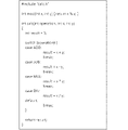
- FIG. 2 is a diagram showing an example of the source code of a C language program that can obtain an input object file 101 as a result of compilation.
- compiling the source code of FIG. 2 for the ARM architecture gives an example of the input object file 101.
- the object file obtained from the source code of FIG. 2 is assumed to be used as a library.
- the source code of FIG. 2 is shown for convenience for convenience, and may not be used in the embodiment of the present embodiment.
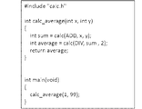
- FIG. 3 is a diagram showing an example of the source code of a C language program that can be compiled and linked to obtain an executable file 102. By linking the object file obtained by compiling the source code of FIG. 3 and the object file obtained by compiling the source code of FIG. 2, an example of the executable file 102 is obtained.
- the function calc of the C language program shown in FIG. 2 performs one of the four arithmetic operations using the arguments x and y for each operation type given by the argument operation.
- the function calc_average of the C language program shown in FIG. 3 calculates the average of two numbers using the function calc shown in FIG.
- One of the methods for realizing the program execution unit 104 is an instruction set simulator.
- the instruction set simulator loads the executable file 102 and starts executing the program from the entry point of the program.
- FIG. 2 shows the operation procedure of the program execution unit 104, which is an instruction set simulator.
- the program execution unit 104 executes the executable file 102 and outputs the required address set and the instruction start address set as the required address information.
- the memory area specifying unit 105 identifies the memory area based on the output required address information.
- the required address set is a set that holds the addresses of binary codes or data that are not to be deleted for each byte.
- the instruction head address set is a set that holds the head address of the executed instruction. The instruction head address set is used when the instruction is decoded in the editing process of the input object file 101.
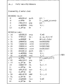
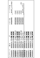
- FIG. 4 is a diagram showing an edited result of disassembling the executable file 102 for the ARM architecture with GNU objdump. Each line in FIG. 4 corresponds to each line in the input object file 101 shown in FIG.
- x is shown at the beginning of the line corresponding to the address of the source code in FIG. 2 required to execute the executable file 102.
- the required address set is expressed as follows.
- the memory area specifying unit 105 identifies the memory area based on the output required address information.
- FIG. 5 is a flowchart showing an example of the processing flow of the program execution unit 104 and the memory area identification unit 105.
- step ST501 the program execution unit 104 starts the loop processing.
- the loop processing is a processing in which execution of each instruction is repeated until the end condition of the program is satisfied in step ST509.
- step ST502 the program execution unit 104 fetches an instruction from the address of the executable file 102 pointed to by the program counter.
- step ST503 the memory area specifying unit 105 adds the address corresponding to the instruction fetched in step ST502 to the required address set byte by byte. For example, when a 4-byte instruction is fetched from address 0 ⁇ 1000, addresses 0 ⁇ 1000, 0 ⁇ 1001, 0 ⁇ 1002, and 0 ⁇ 1003 are added to the required address set.
- step ST504 the memory area specifying unit 105 adds the head address pointed to by the program counter in step ST502 to the instruction head address set. For example, if the address from which the instruction is fetched is address 0 ⁇ 1000, the address 0 ⁇ 1000 is added to the instruction start address set.
- step ST505 the program execution unit 104 decodes the fetched instruction.
- the type of instruction is specified based on the opcode of the instruction, and the instruction operand is obtained from the corresponding instruction.
- step ST506 the program execution unit 104 executes the instruction acquired in step ST505.
- step ST507 the program execution unit 104 determines whether or not the instruction executed in step ST506 is an instruction that involves reading the memory to the code area.
- the instruction involves reading the memory to the code area can be determined from the section table included in the executable file 102.
- the address X of the read destination (access destination) in the executable file 102 is.
- the address X points to the data in the code area.
- the data read here is not an instruction but a constant or a branch destination address embedded in the code area.
- step ST506 when the instruction executed in step ST506 is an instruction accompanied by reading the memory to the code area, that is, when it corresponds to "YES" branching from step ST507 shown in FIG. 5, FIG. Proceed to step ST508 where an example is shown.
- step ST506 if the instruction executed in step ST506 is not an instruction that involves reading memory into the code area, that is, if it corresponds to "NO" branching from step ST507 shown in FIG. 5, FIG. Proceed to step ST509 where an example is shown.
- step ST508 the memory area specifying unit 105 adds an element to the required address set.
- the first address corresponding to the instruction fetched in step ST502 is Y
- the address of the read destination (access destination) in the executable file 102 is X (X> Y)
- the access size is n.
- Y, Y + 1, ..., X + n-1 are added to the required address set.
- steps ST507 and ST508 are additional steps required to handle the case where data other than an instruction is embedded in the code area of the input object file 101. Therefore, these steps are unnecessary when data other than instructions is not embedded in the code area.
- the program execution unit 104 determines whether or not the end condition is satisfied.
- the termination condition is the termination by an interactive operation of the user, or the termination when the program counter reaches a specific address, and is the same as the termination condition of a general instruction set simulator.
- step ST509 branching from step ST509 shown in FIG. 5
- the operation is terminated.
- the end condition is not satisfied, that is, if it corresponds to "NO" branching from step ST509 shown in FIG. 5, the process returns to step ST501 shown in FIG.
- the object file editing unit 106 inputs an executable file 102, an input object file 101, and necessary address information, and outputs an output object file 103 in which unnecessary parts created by rewriting the input object file 101 have been deleted. do.
- FIG. 6 is a flowchart showing an example of the processing flow of the object file editing unit 106 and the correspondence table creation unit 107.
- step ST601 the object file editing unit 106 starts the loop processing.
- the loop processing is a processing in which execution is repeated until all the entries in the section header of the input object file 101 are processed.
- FIG. 7 is a diagram showing an example of a section header of the input object file 101 obtained by compiling the C language program shown in FIG.
- FIG. 7 shows the result of outputting the section header of the input object file 101 by the GNU binutils readelf command.
- Step ST602 of FIG. 6, step ST603 of FIG. 6, step ST604 of FIG. 6, step ST605 of FIG. 6, and step ST606 of FIG. 6 are ... text or. It is executed for each section such as data.
- the correspondence table creation unit 107 creates a correspondence table between the address and the offset.
- the correspondence table holds a pair of the address x and the offset y after loading the executable file 102 for each offset of the byte data in the section.
- FIG. 8 is a diagram showing the result of disassembling the input object file 101 shown in FIG. In FIG. 8, x at the beginning of the line is added to the portion that cannot be deleted in the input object file 101.
- the address 0x82b4 shown in FIG. 4 and the offset 0x14 shown in FIG. 8 can be mentioned.
- step ST602 in FIG. 6 will be further described later.
- step ST603 of FIG. 6 the object file editing unit 106 deletes unnecessary data from the section and rewrites the section using the required address information and the correspondence table between the address and the offset.
- FIG. 9 shows the disassembly result shown in FIG. It is a figure which shows the result of having removed an unnecessary part from a text section.
- step ST603 in FIG. 6 will be further described later.
- step ST604 of FIG. 6 the object file editing unit 106 rewrites the entry of the section header.
- the part to be rewritten is the size of the section.
- the size of the new section is the size of the section after the unnecessary part is deleted in step ST603 of FIG.
- FIG. 10 shows, as an example, in step ST603 of FIG.
- Fig. 9 When the result of the text section rewriting is shown in Fig. 9, ... It is a figure which shows the section header which reflects the size of a text section.
- FIG. 10 ... The size of the text section has been changed to 0x3C bytes.
- step ST605 of FIG. 6 the object file editing unit 106 rewrites the symbol table.
- step ST606 of FIG. 6 the object file editing unit 106 rewrites the relocation table. Specifically, when the location moved (rewritten) in step ST603 of FIG. 6 is a relocation location (that is, one of the entries stored in the relocation table), an offset indicating the relocation location is indicated. To the new offset. Also, the relocation entry corresponding to the area deleted in step ST603 of FIG. 6 is invalidated.
- step ST607 of FIG. 6 the object file editing unit 106 determines whether or not all the entries in the section header of the input object file 101 have been processed.
- step ST607 the operation is terminated. do.
- step ST601 the example shown in FIG. return.
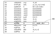
- FIG. 11 is of FIG. It is a figure which shows the example of the relocation table before rewriting when the text section is rewritten as shown in FIG. Further, FIG. 12 is a diagram showing the result of appropriately rewriting the relocation table shown in FIG.
- each entry whose type has been rewritten to R_ARM_NONE corresponds to the deleted area. Also, each entry whose type is other than R_ARM_NONE has its offset corrected (see bold).
- the offset of entry 1101 before rewriting in FIG. 11 is 0x3c, but in the corresponding entry 1201 after rewriting in FIG. 12, the offset is rewritten to 0x28.
- step ST606 This is shown in Fig. 8.
- the relocation target location 801 that existed at the offset 0x3c of the text section was changed to the section of step ST603 of FIG. It corresponds to moving to the relocation target location 901 existing at the offset 0x28 of the text section.
- step ST606 in FIG. 6 will be further described later.
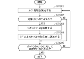
- FIG. 13 is a flowchart showing a detailed processing flow of step ST602 of FIG. When an example is shown in FIG. 13, the target section name is input.
- step ST1301 the object file editing unit 106 starts loop processing.
- the loop processing is a processing in which execution is repeated until all the entries in the symbol table of the input object file 101 are processed.
- step ST1302 the object file editing unit 106 determines whether or not the symbol of the entry in the symbol table is the symbol of the target section.
- step ST1303 when the symbol of the entry in the symbol table is the symbol of the target section, that is, when it corresponds to "YES" branching from step ST1302 shown in FIG. 13, the process proceeds to step ST1303.
- the symbol of the entry in the symbol table is not the symbol of the target section, that is, if it corresponds to "NO" branching from step ST1302 shown in FIG. 13, the example is shown in step ST1305. Proceed to.
- step ST1303 the object file editing unit 106 searches the symbol table of the executable file 102, and obtains the address x and the size n corresponding to the symbol name of the entry of the currently targeted symbol table.
- step ST1304 the object file editing unit 106 corresponds to each byte data between the area from the address x to the address x + n-1 and the area from the offset y to the offset y + n-1, where the offset held by the entry in the symbol table is y. Is added to the correspondence table between addresses and offsets.
- step ST1305 the object file editing unit 106 determines whether or not all the entries in the symbol table of the input object file 101 have been processed.
- step ST1301 shown in FIG. 13 is an example. return.
- FIG. 14 is a flowchart showing a detailed processing flow of step ST603 of FIG.
- necessary address information and a correspondence table between addresses and offsets are input, and unnecessary codes or data are deleted from the target section.
- the unnecessary parts are deleted by overwriting and copying only the necessary parts in order from the top.
- an offset and offset correspondence table showing the correspondence of data before and after section rewriting is output.
- the entry in the offset-to-offset correspondence table is an offset pair (i, j), which holds that the byte data that was in offset i before rewriting moved to offset j after rewriting.
- the offset j is initialized to 0.
- the offset j indicates the byte offset of the writing destination, and is updated as appropriate.
- the value obtained by adding the offset from the beginning of the section indicates the writing destination.
- step ST1402 the object file editing unit 106 starts loop processing.
- the offset i indicates the byte offset of the read source.
- step ST1403 the object file editing unit 106 acquires the address x corresponding to the offset i from the correspondence table between the address and the offset.
- step ST1404 the object file editing unit 106 determines whether or not the address x is included in the required address set.
- step ST1405 in which an example is shown in 14.
- step ST1408 for which an example is shown in FIG.
- step ST1405 the object file editing unit 106 overwrites (moves) the byte data of offset i at the position of offset j.
- step ST1406 the object file editing unit 106 adds an offset pair (i, j) to the offset table.
- step ST1407 the object file editing unit 106 increments j by 1.
- step ST1409 when the offset i corresponds to the end of the symbol, that is, when it corresponds to "YES” branching from step ST1408 shown in FIG. 14, the process proceeds to step ST1409.
- the offset i does not correspond to the end of the symbol, that is, if it corresponds to "NO" branching from step ST1408 shown in FIG. 14, go to step ST1410 shown in FIG. move on.
- step ST1409 the object file editing unit 106 rewrites the offset and size of the symbol table entry obtained by the search in step ST1408, respectively.
- the offset pair (k, l) is searched from the offset table corresponding to the offset using the offset k of the entry of the symbol table. Then, the offset value is updated with l.
- the size is j-l. In this case, j holds the value of the offset +1 at the end of the symbol after movement, and l holds the offset at the beginning of the symbol after movement.
- FIG. 15 is a diagram showing an example of the symbol table before rewriting. Further, FIG. 16 is a diagram showing an example of the symbol table after the above rewriting.
- Entry 1501 of the symbol table before rewriting corresponds to the function calc.
- the address of the function calc has moved from offset 0x14 to offset 0x00, as shown in the rewrite from FIG. 8 to FIG. Therefore, in the rewritten entry 1601 shown in FIG. 16, the symbol value is rewritten to 0x0.
- the value 0x0 of the symbol of the rewritten entry 1601 shown in FIG. 16 is the value of l obtained in this case.
- j at this time is 0x3C
- the branch destination of the branch instruction may move due to the rewriting in step ST1402 to step ST1410.
- the object file editing unit 106 rewrites the branch destination of the branch instruction to the one after the movement.
- FIG. 17 is a flowchart showing a detailed processing flow of the branch instruction rewriting process in step ST1411 of FIG.
- a section and a branch instruction head address set are input, and the branch destination is rewritten for the instruction whose branch destination is changed among the branch instructions existing in the section.
- step ST1701 the object file editing unit 106 starts the loop processing.
- the loop processing is a processing in which execution is repeated until the processing is performed for the offset pairs (i, j) of all the entries in the offset table.
- step ST1702 the object file editing unit 106 acquires the address x from the correspondence table between the address and the offset using the offset i before rewriting.
- step ST1703 the object file editing unit 106 determines whether or not the address x is included in the instruction head address set.
- step ST1704 for which an example is shown in FIG.
- step ST1709 the address x is included in the instruction head address set, that is, when it corresponds to "YES" branching from step ST1703 shown in FIG. 17
- the offset j after rewriting is executed. It is determined that the address is not the start address of the instruction, and the process proceeds to step ST1709 shown in FIG.
- step ST1704 the object file editing unit 106 decodes the data at offset j as an instruction.
- step ST1705 the object file editing unit 106 determines whether or not the instruction at offset j is a direct branch instruction based on the result of decoding in step ST1704.
- the direct branch instruction is a branch instruction other than the register indirect branch instruction.
- step ST1704 the instruction at offset j is a direct branch instruction, that is, when it corresponds to "YES” branching from step ST1705 shown in FIG. 17
- the process proceeds to step ST1709 shown in FIG. ..
- step ST1706 the object file editing unit 106 calculates the branch destination address of the branch instruction.
- direct branching consider PC-relative branching.
- the relative address k from the offset j (k is a positive or negative integer) is stored in the instruction field.
- the object file editing unit 106 uses i + k as the offset before rewriting to search the correspondence table between the offsets and the offsets.
- step ST1707 the object file editing unit 106 determines whether or not the above search was successful, that is, whether or not an offset pair (i + k, m) was obtained.
- step ST1708 shown in FIG.
- step ST1709 shown in FIG.
- step ST1708 the object file editing unit 106 writes mi to the instruction field based on the obtained offset pair (i + k, m). That is, the offset of the branch destination is rewritten.
- step ST1709 the object file editing unit 106 determines whether or not processing has been performed on the offset pairs (i, j) of all the entries in the offset and offset correspondence table.
- step ST1709 when processing is performed on the offset pair (i, j) of all the entries in the offset and offset correspondence table, that is, it corresponds to "YES" branching from step ST1709 shown in FIG. If so, the operation is terminated. On the other hand, if the offset pair of unprocessed entries remains, that is, if it corresponds to "NO" branching from step ST1709, an example is shown in FIG. Return to step ST1701.
- FIG. 18 is a flowchart showing a detailed processing flow of the relocation table rewriting process of step ST606 of FIG.
- the input is the input object file 101, the section name, the offset and offset correspondence table, and the output is the output object file 103 with the relocation table modified.
- step ST1801 the object file editing unit 106 starts the loop processing.
- the loop processing is a processing in which execution is repeated until all the entries in the relocation table corresponding to the input section name are processed.
- the entered section name is.
- the relocation table is. text. It is stored in a section named rel.
- step ST1802 the object file editing unit 106 searches for an offset pair from the offset table of offsets, with the offset i of the relocation entry as the offset before rewriting.
- step ST1803 the object file editing unit 106 determines whether or not the above search is successful, that is, whether or not an offset pair (i, j) is obtained.
- step ST1805 shown in FIG.
- step ST1804 the object file editing unit 106 overwrites the offset i stored in the entry of the relocation table with the rewritten offset j.
- step ST1805 the object file editing unit 106 determines whether or not all the entries in the relocation table corresponding to the input section name have been processed.
- step ST1805 shown in FIG. 18 is an example.
- 19 and 20 are diagrams schematically illustrating a hardware configuration when the program size reducing device shown in FIG. 1 is actually operated.
- FIGS. 19 and 20 may not match the configurations illustrated in FIG. 1, but the configuration exemplified in FIG. 1 is a conceptual unit. It is due to the fact that it is shown.
- At least one configuration exemplified in FIG. 1 comprises a plurality of hardware configurations exemplified in FIGS. 19 and 20, and one configuration exemplified in FIG. 1 comprises FIGS. 19 and 20. In some cases, it corresponds to a part of the hardware configuration exemplified in FIG. 1, and further, in some cases, a plurality of configurations exemplified in FIG. 1 are provided in one hardware configuration exemplified in FIGS. 19 and 20. It can be assumed.
- FIG. 19 as a hardware configuration for realizing the program execution unit 104, the memory area specifying unit 105, the object file editing unit 106, and the correspondence table creation unit 107 in FIG. 1, the processing circuit 1102A that performs calculations and information are displayed. A storage device 1103 that can be stored is shown.
- FIG. 20 shows a processing circuit 1102B that performs an operation as a hardware configuration for realizing the program execution unit 104, the memory area identification unit 105, the object file editing unit 106, and the correspondence table creation unit 107 in FIG.
- the storage unit (not shown) that stores the correspondence table between the address and the offset is realized by the storage device 1103 or another storage device (not shown here).
- the storage device 1103 is, for example, a hard disk drive (Hard disk drive, that is, HDD), a random access memory (random access memory, that is, RAM), a read-only memory (read only memory, that is, ROM), a flash memory, and an erase program.
- Hard disk drive that is, HDD
- random access memory random access memory
- read-only memory read only memory
- flash memory and an erase program.
- Memory storage including volatile or non-volatile semiconductor memory, magnetic disk, flexible disk, optical disk, compact disk, mini disk or DVD, such as read only memory (EPROM) and electricalally random, read-only memory (EEPROM). It may be a medium) or any storage medium that will be used in the future.
- the processing circuit 1102A may execute a program stored in a storage device 1103, an external CD-ROM, an external DVD-ROM, an external flash memory, or the like. That is, for example, it may be a central processing unit (that is, a CPU), a microprocessor, a microcomputer, or a digital signal processor (that is, a DSP).
- a central processing unit that is, a CPU
- a microprocessor that is, a microcomputer
- a digital signal processor that is, a DSP
- the processing circuit 1102A executes a program stored in a storage device 1103, an external CD-ROM, an external DVD-ROM, an external flash memory, or the like, the program execution unit 104, the memory area identification unit 105, etc.
- the object file editing unit 106 and the correspondence table creation unit 107 are realized by software, firmware, or a combination of software and firmware in which a program stored in the storage device 1103 is executed by the processing circuit 1102A.
- the functions of the program execution unit 104, the memory area identification unit 105, the object file editing unit 106, and the correspondence table creation unit 107 may be realized, for example, by linking a plurality of processing circuits.
- the software and firmware may be described as a program and stored in the storage device 1103.
- the processing circuit 1102A realizes the above function by reading and executing the program stored in the storage device 1103. That is, the storage device 1103 may store a program in which the above functions are eventually realized by being executed by the processing circuit 1102A.
- processing circuit 1102B may be dedicated hardware. That is, for example, a single circuit, a composite circuit, a programmed processor, a parallel programmed processor, an integrated circuit (application specific integrated circuit, that is, an ASIC), a field-programmable gate array (FPGA), or a combination thereof. It may be a circuit.
- the program execution unit 104 When the processing circuit 1102B is dedicated hardware, the program execution unit 104, the memory area specifying unit 105, the object file editing unit 106, and the correspondence table creation unit 107 are realized by operating the processing circuit 1102B.
- the functions of the program execution unit 104, the memory area identification unit 105, the object file editing unit 106, and the correspondence table creation unit 107 may be realized by separate circuits or may be realized by a single circuit.
- the functions of the program execution unit 104, the memory area identification unit 105, the object file editing unit 106, and the correspondence table creation unit 107 are realized in the processing circuit 1102A, which partially executes the program stored in the storage device 1103. It may be realized in the processing circuit 1102B, which is a part of the dedicated hardware.
- the program size reducing device includes a memory area specifying unit 105, a correspondence table creating unit 107, and an object file editing unit 106.
- the memory area specifying unit 105 is the first address of the first source code in the executable file 102 (that is, the execution of the executable file 102) accessed by the execution of the executable file 102 linked to the input object file 101.
- the source code address of the executable file 102 which is sometimes required), is specified as a memory area.
- the correspondence table creation unit 107 creates a correspondence table between the first address in the memory area and the first offset from the beginning of the section of the second source code in the input object file 101.
- the object file editing unit 106 determines the second source code of the first offset that does not correspond to the first address in the memory area (that is, the executable file 102 that is not necessary when the executable file 102 is executed). Edit to delete the source code of the input object file 101, which has an offset corresponding to the source code.
- the program size reducing device includes a processing circuit 1102A for executing a program and a storage device 1103 for storing the program to be executed. Then, when the processing circuit 1102A executes the program, the following operations are realized.
- the first address of the first binary code in the executable file 102 which is accessed by the execution of the executable file 102 linked to the input object file 101, is specified as the memory area. Then, based on the correspondence table between the first address in the memory area and the first offset from the beginning of the section of the second binary code in the input object file 101, the first address does not correspond to the first address in the memory area. The second binary code of the offset is removed.
- the program size reducing device includes a processing circuit 1102B which is dedicated hardware. Then, the processing circuit 1102B, which is dedicated hardware, performs the following operations.
- the processing circuit 1102B which is dedicated hardware, stores the first address of the first binary code in the executable file 102, which is accessed by the execution of the executable file 102 linked to the input object file 101, in the memory. Specify as an area. Then, based on the correspondence table between the first address in the memory area and the first offset from the beginning of the section of the second binary code in the input object file 101, the first address does not correspond to the first address in the memory area. Edit to remove the second binary code of the offset of.
- the program size can be reduced by rewriting the input object file 101 used when constructing the software, instead of directly rewriting the executable file 102. Therefore, the rewritten output object file 103 can be reused in other programs.
- the output object file 103 having only the function can be reused for another program. For example, if OpenSSL, which is a security library, is linked and an executable file 102 that executes the encryption test vector of AES-GCM-256 is given as an input, the encryption algorithm is AES, the encryption mode is GCM, and the key length is 256 bytes. You can get a lightweight library with specialized functions.
- the instruction corresponding to the first binary code is an instruction accompanied by reading the memory to the code area.
- the memory area specifying unit 105 has at least the first address of the first binary code (that is, the address of the binary code of the executable file 102 required when the executable file 102 is executed) and the read destination by the instruction.
- Second address (for example, access destination address X) is specified as a memory area. According to such a configuration, even if data other than the instruction is embedded in the code area, the address that cannot be deleted (that is, the binary code of the executable file 102 required at the time of executing the executable file 102). Address) can be specified as a memory area.
- the memory area specifying unit 105 has a required address set including the first address of the first binary code and the head of the instruction corresponding to the first binary code.
- the memory area is specified by using the instruction head address set including the address. According to such a configuration, even when the instruction corresponding to the binary code in the executable file 102 is a variable-length instruction, the memory area can be appropriately specified.
- a memory area can be specified corresponding to an instruction set such as ARM's Thumb instruction set or PowerPC's VLE.
- the instruction corresponding to the second binary code of the first offset not corresponding to the first address in the memory area is a direct branch instruction. If there is, an edit is performed to rewrite the second offset of the branch destination by the direct branch instruction.
- the input object file 101 can be edited in a reusable state even when the offset of the branch destination of the direct branch instruction is moved due to the reduction of the program size. That is, even in the input object file 101 including the direct branch instruction, the program size can be appropriately reduced.
- the object file editing unit 106 relocates the relocation location with the deletion of the second binary code of the first offset that does not correspond to the first address in the memory area. If so, edit to rewrite the third offset indicating the relocation location in the relocation table. According to such a configuration, the input object file 101 can be edited in a reusable state even when the binary code or data of the relocation location is left without being deleted when the program size is reduced. ..
- the program size reduction program is linked to the input object file 101 on the computer by being installed and executed on the computer (for example, processing circuit 1102A or processing circuit 1102B).
- the first address of the first binary code in the executable file 102 which is accessed by the execution of the executable file 102, is specified as a memory area.
- the computer corresponds to the first address in the memory area based on the correspondence table between the first address in the memory area and the first offset from the beginning of the section of the second binary code in the input object file 101. Do not edit to remove the second binary code of the first offset.
- the program size can be reduced by rewriting the input object file 101 used when constructing the software, instead of directly rewriting the executable file 102. Therefore, the rewritten output object file 103 can be reused in other programs.
- the above program may be stored in a portable recording medium such as a magnetic disk, a flexible disk, an optical disk, a compact disk, a Blu-ray (registered trademark) disk, or a DVD, which can be read by a computer. Then, a portable recording medium in which a program for realizing the above functions is stored may be commercially distributed.
- a portable recording medium such as a magnetic disk, a flexible disk, an optical disk, a compact disk, a Blu-ray (registered trademark) disk, or a DVD, which can be read by a computer.
- a portable recording medium in which a program for realizing the above functions is stored may be commercially distributed.
- the first binary code in the executable file 102 accessed by the execution of the executable file 102 linked to the input object file 101 is the first.
- the address of is specified as a memory area. Then, based on the correspondence table between the first address in the memory area and the first offset from the beginning of the section of the second binary code in the input object file 101, the first address does not correspond to the first address in the memory area. Delete the second binary code of the offset.
- the program size can be reduced by rewriting the input object file 101 used when constructing the software, instead of directly rewriting the executable file 102. Therefore, the rewritten output object file 103 can be reused in other programs.
- each component in the embodiments described above is a conceptual unit, and within the scope of the technique disclosed herein, one component comprises a plurality of structures. It is assumed that one component corresponds to a part of a structure, and further, a case where a plurality of components are provided in one structure is included.
- each component in the above-described embodiment shall include a structure having another structure or shape as long as it exhibits the same function.
- each component described in the above-described embodiment is assumed to be software or firmware and corresponding hardware, and in both concepts, each component is a "part". Alternatively, it is referred to as a "processing circuit” or the like.
- Program size reduction device 101 Input object file, 102 Executable file, 103 Output object file, 104 Program execution unit, 105,3001 Memory area identification unit, 106,3003 Object file editing unit, 107,3002 Correspondence table creation unit, 801,901 Relocation target location, 1102A, 1102B processing circuit, 1103 storage device.
Landscapes
- Engineering & Computer Science (AREA)
- General Engineering & Computer Science (AREA)
- Theoretical Computer Science (AREA)
- Software Systems (AREA)
- Physics & Mathematics (AREA)
- General Physics & Mathematics (AREA)
- Devices For Executing Special Programs (AREA)
Abstract
再利用可能な状態で、プログラムサイズを低減する。プログラムサイズ低減装置は、オブジェクトファイルにリンクされた実行可能ファイルの実行によってアクセスされる第1のバイナリコードの第1のアドレスを、メモリ領域として特定するメモリ領域特定部と、第1のアドレスと、オブジェクトファイルにおける第2のバイナリコードのセクション先頭からのオフセットとの対応表を作成する対応表作成部と、対応表に基づいて、第1のアドレスに対応しないオフセットの第2のバイナリコードを削除するオブジェクトファイル編集部とを備える。
Description
本願明細書に開示される技術は、プログラムサイズ低減装置、プログラムサイズ低減プログラム、および、プログラムサイズ低減方法に関するものである。
特定の機能を実現するために機械などに組み込まれる組み込みシステムでは、一般にメモリの低減が重要である。組み込みシステムでは、少ないリソースでソフトウェアを実行する必要がある。よって、動作のために必要となるメモリのサイズが大きくなると、その分だけメモリモジュールの追加または高価なメモリ内蔵マイコンなどが必要となってしまう。このため、製品の製造コストを下げるためには、ソフトウェアの省メモリ化を行うことが必要である。
また、近年ではIoT(Internet of Things)への対応のため、組み込みシステムの高機能化が進んでいる。組み込みシステムがインターネットに接続される環境では、セキュリティー確保のための暗号化および復号、通信量を削減するための圧縮および展開、さらには、アプリケーション間の通信のためのプロトコル処理などが必要である。
このような高機能化された組み込みシステムを短期間で開発するためには、既存ライブラリを利用することが有効な手段である。既存ライブラリとしては、たとえば、COTS(Commercial Off the Shelf Software)、または、OSS(Open Source Software)などが考えられる。
しかしながら、これらの既存ライブラリは多用途向けに汎用化されている場合が多く、ソフトウェアにおけるプログラムにライブラリをリンクさせた結果として、不要な機能までリンク結果に含まれる場合がある。このため、メモリに対応するプログラムのサイズが必要以上に大きくなり、組み込みシステムとして用いることが困難となる場合がある。
これらの汎用的な既存ライブラリの多くは、PCまたはサーバー向けのものであり、そのままでは組み込みシステムとして用いることは難しい。このため、既存ライブラリを組み込みシステムに対して用いる場合には、そのソースコードから不要な部分を削除するというチューニングが必要である。
ただし、人手によるチューニング作業は、単調で、かつ、誤りが生じがちである。また、COTSの場合はソースコードが提供されないため、人手によるチューニングが実質的には困難である。
ソースコードが存在しない場合にプログラムのサイズを削除する他の方法としては、たとえば、特許文献1に記載される方法がある。特許文献1に記載される方法では、プログラムを実行し、当該実行時に実行されなかった部分のバイナリコードを削除する。
しかしながら、特許文献1に記載される方法では、実行されたプログラムのバイナリコードを直接書き換えることとなるため、書き換えられたプログラムを他の用途で再利用することができないという問題があった。
本願明細書に開示される技術は、以上に記載されたような問題を鑑みてなされたものであり、ソースコードが得られないライブラリである場合を含め、再利用可能な状態で、プログラムサイズを低減するための技術である。
本願明細書に開示される技術の第1の態様であるプログラムサイズ低減装置は、入力オブジェクトファイルにリンクされた実行可能ファイルの実行によってアクセスされる、前記実行可能ファイルにおける第1のバイナリコードの第1のアドレスを、メモリ領域として特定するためのメモリ領域特定部と、前記メモリ領域における前記第1のアドレスと、前記入力オブジェクトファイルにおける第2のバイナリコードのセクション先頭からの第1のオフセットとの対応表を作成するための対応表作成部と、前記対応表に基づいて、前記メモリ領域における前記第1のアドレスに対応しない前記第1のオフセットの前記第2のバイナリコードを削除する編集を行うためのオブジェクトファイル編集部とを備える。
本願明細書に開示される技術の第2の態様であるプログラムサイズ低減プログラムは、コンピュータにインストールされて実行されることによって、前記コンピュータに、入力オブジェクトファイルにリンクされた実行可能ファイルの実行によってアクセスされる、前記実行可能ファイルにおける第1のバイナリコードの第1のアドレスを、メモリ領域として特定させ、前記コンピュータに、前記メモリ領域における前記第1のアドレスと、前記入力オブジェクトファイルにおける第2のバイナリコードのセクション先頭からの第1のオフセットとの対応表に基づいて、前記メモリ領域における前記第1のアドレスに対応しない前記第1のオフセットの前記第2のバイナリコードを削除する編集を行わせる。
本願明細書に開示される技術の第3の態様であるプログラムサイズ低減方法は、入力オブジェクトファイルにリンクされた実行可能ファイルの実行によってアクセスされる、前記実行可能ファイルにおける第1のバイナリコードの第1のアドレスを、メモリ領域として特定し、前記メモリ領域における前記第1のアドレスと、前記入力オブジェクトファイルにおける第2のバイナリコードのセクション先頭からの第1のオフセットとの対応表に基づいて、前記メモリ領域における前記第1のアドレスに対応しない前記第1のオフセットの前記第2のバイナリコードを削除する編集を行う。
本願明細書に開示される技術の少なくとも第1、2、3の態様によれば、実行可能ファイルを直接書き換えるのではなく、ソフトウェアを構築するときに際に用いられたオブジェクトファイルを書き換えることによってプログラムサイズを低減させることができる。そのため、書き換えられた出力オブジェクトファイルを他のプログラムでも再利用することができる。
また、本願明細書に開示される技術に関連する目的と、特徴と、局面と、利点とは、以下に示される詳細な説明と添付図面とによって、さらに明白となる。
以下、添付される図面を参照しながら実施の形態について説明する。以下の実施の形態では、技術の説明のために詳細な特徴なども示されるが、それらは例示であり、実施の形態が実施可能となるためにそれらすべてが必ずしも必須の特徴ではない。
なお、図面は概略的に示されるものであり、説明の便宜のため、適宜、構成の省略、または、構成の簡略化が図面においてなされるものである。また、異なる図面にそれぞれ示される構成などの大きさおよび位置の相互関係は、必ずしも正確に記載されるものではなく、適宜変更され得るものである。また、断面図ではない平面図などの図面においても、実施の形態の内容を理解することを容易にするために、ハッチングが付される場合がある。
また、以下に示される説明では、同様の構成要素には同じ符号を付して図示し、それらの名称と機能とについても同様のものとする。したがって、それらについての詳細な説明を、重複を避けるために省略する場合がある。
また、以下に記載される説明において、ある構成要素を「備える」、「含む」または「有する」などと記載される場合、特に断らない限りは、他の構成要素の存在を除外する排他的な表現ではない。
また、以下に記載される説明において、「第1の」または「第2の」などの序数が用いられる場合があっても、これらの用語は、実施の形態の内容を理解することを容易にするために便宜上用いられるものであり、これらの序数によって生じ得る順序などに限定されるものではない。
<プログラムサイズ低減装置の概念的な構成について>
図21は、本実施の形態に関するプログラムサイズ低減装置の構成(機能部)の例を概念的に示す図である。
図21は、本実施の形態に関するプログラムサイズ低減装置の構成(機能部)の例を概念的に示す図である。
図21に例示されるようにプログラムサイズ低減装置は、メモリ領域特定部3001と、対応表作成部3002と、オブジェクトファイル編集部3003とを備える。
メモリ領域特定部3001は、入力オブジェクトファイルにリンクされた実行可能ファイルの実行によってアクセスされる、実行可能ファイルにおける第1のバイナリコードの第1のアドレスを、メモリ領域として特定する。対応表作成部3002は、メモリ領域における第1のアドレスと、入力オブジェクトファイルにおける第2のバイナリコードのセクション先頭からの第1のオフセットとの対応表を作成する。オブジェクトファイル編集部3003は、対応表に基づいて、メモリ領域における第1のアドレスに対応しない第1のオフセットの第2のバイナリコードを削除する編集を行う。
以下の実施の形態において図面などを用いて示されるそれぞれの構成は、上記の図21に示された構成の例をさらに具体的に示すものである。
<実施の形態>
以下、本実施の形態に関するプログラムサイズ低減装置、プログラムサイズ低減プログラム、および、プログラムサイズ低減方法について説明する。
以下、本実施の形態に関するプログラムサイズ低減装置、プログラムサイズ低減プログラム、および、プログラムサイズ低減方法について説明する。
<プログラムサイズ低減装置の構成について>
図1は、本実施の形態に関するプログラムサイズ低減装置10の構成の例を概念的に示す図である。
図1は、本実施の形態に関するプログラムサイズ低減装置10の構成の例を概念的に示す図である。
図1に例が示されるプログラムサイズ低減装置10は、軽量化対象である入力オブジェクトファイル101と、入力オブジェクトファイル101とリンクする実行可能ファイル102とを入力とし、実行可能ファイル102の実行に不要な部分が論理的に削除された軽量化済みの出力オブジェクトファイル103を出力する。
図1に例が示されるプログラムサイズ低減装置10は、プログラム実行部104と、メモリ領域特定部105と、オブジェクトファイル編集部106と、対応表作成部107とを備える。
プログラム実行部104は、実行可能ファイル102をロードし、かつ、実行可能ファイル102を実行する。メモリ領域特定部105は、実行可能ファイル102の実行時にアクセスされるバイナリコードのアドレスを記録し、当該アドレス群を、実行可能ファイル102の実行時に必要となるメモリ領域として特定する。
オブジェクトファイル編集部106は、メモリ領域特定部105によって特定されたメモリ領域を用いて、入力オブジェクトファイル101から実行可能ファイル102を実行するために不要な部分を削除するとともに、入力オブジェクトファイル101のセクションヘッダテーブル、シンボルテーブルおよびリロケーションテーブルを書き換える。そして、オブジェクトファイル編集部106は、メモリ領域特定部105によって特定されたメモリ領域に対応しない入力オブジェクトファイル101中のバイナリコードおよびデータを削除することで、プログラムサイズを削減する。
このとき、入力オブジェクトファイル101を編集するためには、メモリ領域に対応する入力オブジェクトファイル101中の領域が既知である必要がある。そこで、オブジェクトファイル編集部106は、対応表作成部107によって作成された、メモリ領域におけるアドレスと、入力オブジェクトファイル101中のセクション先頭からのオフセットとの対応表を利用して、入力オブジェクトファイル101を編集する。
図2は、コンパイルした結果入力オブジェクトファイル101を得ることができるC言語プログラムのソースコードの例を示す図である。たとえば、図2のソースコードをARMアーキテクチャ向けにコンパイルすると入力オブジェクトファイル101の1例を得られる。図2のソースコードから得られるオブジェクトファイルは、ライブラリとして利用することが想定される。なお、図2のソースコードは説明のために便宜上図示されたものであり、本実施の形態の実施において用いられなくてもよい。また、図3は、コンパイルおよびリンクして実行可能ファイル102を得ることができるC言語プログラムのソースコードの例を示す図である。図3のソースコードをコンパイルして得られるオブジェクトファイルと、図2のソースコードをコンパイルして得られるオブジェクトファイルとをリンクすると、実行可能ファイル102の1例が得られる。
以降の説明では、図2に例として示されたソースコードをコンパイルして得られた入力オブジェクトファイル101から、図3に例が示された実行可能ファイル102のバイナリコードによるプログラムを実行するために不要な部分を削除する場合を考える。
図2に示されるC言語プログラムの関数calcは、引数operationで与えられる演算種類ごとに引数xとyとを用いて四則演算のいずれかを行う。図3に示されるC言語プログラムの関数calc_averageは、図2に示される関数calcを用いて2数の平均を計算する。
関数calcでの計算および関数calc_averageでの計算では、加算および除算のみを用いる。このため、図3に示されたソースコードによるプログラムを実行するためには、図2の関数calcにおける減算および乗算のソースコードに対応するバイナリコードは不要である。
プログラム実行部104の実現方法の1つは、命令セットシミュレータである。命令セットシミュレータは、実行可能ファイル102をロードし、さらに、プログラムのエントリーポイントからプログラムの実行を開始する。命令セットシミュレータの命令実行方式にはインタプリタ方式またはバイナリ変換方式などが存在するが、本実施の形態ではいずれの方式が採用されてもよい。
図2では、命令セットシミュレータであるプログラム実行部104の動作手順が示される。
図2では、プログラム実行部104は、実行可能ファイル102を実行し、必要アドレス情報として必要アドレス集合と命令先頭アドレス集合とを出力する。メモリ領域特定部105は、出力された必要アドレス情報に基づいて、メモリ領域を特定する。
必要アドレス集合は、削除対象外のバイナリコードまたはデータのアドレスをバイトごとに保持する集合である。また、命令先頭アドレス集合は、実行された命令の先頭のアドレスを保持する集合である。命令先頭アドレス集合は、入力オブジェクトファイル101の編集処理において命令をデコードする際に用いられる。
例として、図3に示されるC言語プログラムをコンパイルして得られる実行可能ファイル102を実行するために必要となる必要アドレス情報を考える。
図4は、ARMアーキテクチャ向けの実行可能ファイル102をGNU objdumpでディスアセンブルした結果を編集したものを示す図である。図4におけるそれぞれの行は、図2に示された入力オブジェクトファイル101のそれぞれの行に対応している。
図4において、実行可能ファイル102を実行するために必要となる図2中のソースコードのアドレスと対応する行の先頭には、xが示されている。
この場合、必要アドレス集合は、以下のように表される。
{整数n | 0x82b4<=n<0x82e0または0x82f8<=n<0x8300 }
また、命令先頭アドレス集合は、以下のように表される。
また、命令先頭アドレス集合は、以下のように表される。
{0x82b4,0x82b8,0x82bc,0x82c0,0x82c4,0x82c8,0x82cc,0x82d0,0x82d4,0x82d8,0x82dc,0x82f8,0x82fc}
メモリ領域特定部105は、出力されたこれらの必要アドレス情報に基づいて、メモリ領域を特定する。
メモリ領域特定部105は、出力されたこれらの必要アドレス情報に基づいて、メモリ領域を特定する。
図5は、プログラム実行部104およびメモリ領域特定部105の処理フローの例を示すフローチャートである。
図5に例が示されるように、ステップST501では、プログラム実行部104がループ処理を開始する。当該ループ処理は、ステップST509においてプログラムの終了条件が満たされるまで1命令ずつの実行を繰り返す処理である。
次に、ステップST502では、プログラム実行部104が、プログラムカウンターが指す実行可能ファイル102のアドレスから命令をフェッチする。
次に、ステップST503では、メモリ領域特定部105が、ステップST502でフェッチされた命令に対応するアドレスを、バイトごとに必要アドレス集合に加える。たとえば、0×1000番地から4バイトの命令がフェッチされた場合、0×1000番地、0×1001番地、0×1002番地および0×1003番地を必要アドレス集合に加える。
次に、ステップST504では、メモリ領域特定部105が、ステップST502でプログラムカウンターが指す先頭のアドレスを、命令先頭アドレス集合に追加する。たとえば、命令をフェッチされたアドレスが0×1000番地である場合、命令先頭アドレス集合に0×1000番地を加える。
次に、ステップST505では、プログラム実行部104が、フェッチされた命令をデコードする。当該デコードでは、命令のオペコードに基づいて命令の種類を特定し、さらに、命令オペランドを対応する命令から取得する。
次に、ステップST506では、プログラム実行部104が、ステップST505で取得された命令を実行する。
次に、ステップST507では、プログラム実行部104が、ステップST506で実行された命令がコード領域へのメモリ読み出しを伴う命令であるか否かを判定する。
命令がコード領域へのメモリ読み出しを伴うか否かは、実行可能ファイル102に含まれるセクションテーブルから判定することができる。たとえば、実行可能ファイル102における読み出し先(アクセス先)のアドレスXが.textセクションに含まれている場合、アドレスXはコード領域中のデータを指す。なお、ここで読み出されるデータは、命令ではなく、コード領域に埋め込まれた定数または分岐先アドレスである。
そして、ステップST506で実行された命令がコード領域へのメモリ読み出しを伴う命令である場合、すなわち、図5に例が示されるステップST507から分岐する「YES」に対応する場合には、図5に例が示されるステップST508へ進む。
一方で、ステップST506で実行された命令がコード領域へのメモリ読み出しを伴う命令でない場合、すなわち、図5に例が示されるステップST507から分岐する「NO」に対応する場合には、図5に例が示されるステップST509へ進む。
ステップST508では、メモリ領域特定部105が、必要アドレス集合に要素を追加する。具体的には、ステップST502でフェッチされた命令に対応する先頭のアドレスをYとし、実行可能ファイル102における読み出し先(アクセス先)のアドレスをX(X>Y)とし、アクセスサイズをnとする場合、Y、Y+1、…、X+n-1を必要アドレス集合に加える。
たとえば、ステップST502でフェッチされた命令に対応する先頭のアドレスが図4に示された0x82b8であり、読み出されたコード領域のデータが0x82ccの4バイトデータである場合、X=0x82cc、Y=0x82b8、n=4となり、必要アドレス集合には、0x82b8(=Y)、0x82b9、…、0x82ce、0x82cf(X+3)が追加される。
なお、ステップST507およびステップST508は、入力オブジェクトファイル101のコード領域中に命令以外のデータが埋め込まれた場合を扱うために必要となる付加的なステップである。そのため、コード領域に命令以外のデータが埋め込まれていない場合には、これらのステップは不要である。
ステップST509では、プログラム実行部104が、終了条件が満たされたか否かを判定する。ここで、終了条件は、ユーザーの対話的操作による終了、または、プログラムカウンターが特定のアドレスに到達した場合などであり、一般的な命令セットシミュレータの終了条件と同様である。
そして、終了条件が満たされた場合、すなわち、図5に例が示されるステップST509から分岐する「YES」に対応する場合には、動作を終了する。一方で、終了条件が満たされていない場合、すなわち、図5に例が示されるステップST509から分岐する「NO」に対応する場合には、図5に例が示されるステップST501に戻る。
次に、オブジェクトファイル編集部106の詳細について説明する。オブジェクトファイル編集部106は、実行可能ファイル102と、入力オブジェクトファイル101と、必要アドレス情報とを入力とし、入力オブジェクトファイル101を書き換えて作成される不要箇所が削除済みである出力オブジェクトファイル103を出力する。
図6は、オブジェクトファイル編集部106および対応表作成部107の処理フローの例を示すフローチャートである。
図6に例が示されるように、ステップST601では、オブジェクトファイル編集部106がループ処理を開始する。当該ループ処理は、入力オブジェクトファイル101のセクションヘッダのすべてのエントリーに対して処理が行われるまで実行を繰り返す処理である。
図7は、図2に示されたC言語プログラムをコンパイルして得られる入力オブジェクトファイル101の、セクションヘッダの例を示す図である。図7は、GNU binutilsのreadelfコマンドで入力オブジェクトファイル101のセクションヘッダを出力させた結果を示している。
図7に示されるように、セクションヘッダのエントリーとして、.textまたは.dataなどが存在する。そして、それぞれのエントリーは、セクションごとのファイルオフセットなどを保持する。
図6のステップST602、図6のステップST603、図6のステップST604、図6のステップST605および図6のステップST606は、.textまたは.dataなどのセクションごとに実行される。
図6のステップST602では、対応表作成部107が、アドレスとオフセットとの対応表を作成する。当該対応表は、セクション中のバイトデータのオフセットごとに、実行可能ファイル102をロードした後のアドレスxとオフセットyとの対を保持する。
ここで、図4に示された、実行可能ファイル102がディスアセンブルされた結果に対応する、アドレスとオフセットとの対応表を考える。
図8は、図2に示された入力オブジェクトファイル101をディスアセンブルした結果を示す図である。図8では、入力オブジェクトファイル101で削除することができない箇所には、行先頭のxが付されている。アドレスとオフセットとの対応表が保持するxとyとの対の一例として、図4に示されたアドレス0x82b4と、図8に示されたオフセット0x14とが挙げられる。
これは、オフセット0x14は関数calcの.textセクション先頭からのオフセットであり、入力オブジェクトファイル101にリンクされた実行可能ファイル102では、0x82b4に関数calcの先頭が配置されていることを意味する。なお、図6のステップST602の詳細については、さらに後述する。
図6のステップST603では、オブジェクトファイル編集部106が、必要アドレス情報と、アドレスとオフセットとの対応表とを用いて、セクションから不要データを削除してセクションの書き換えを行う。
図9は、図8に示されたディスアセンブル結果における.textセクションから、不要部分が削除された結果を示す図である。
図8では、入力オブジェクトファイル101で削除することができない箇所には、行先頭のxが付されている。よって、図9において残っているコードは、図8において先頭にxが付記されている行に対応する。なお、図6のステップST603の詳細については、さらに後述する。
図6のステップST604では、オブジェクトファイル編集部106が、セクションヘッダのエントリーを書き換える。ここで、書き換え対象となる部分は、セクションのサイズである。新しいセクションのサイズは、図6のステップST603で不要部分が削除された後のセクションのサイズである。
図10は、例として、図6のステップST603での.textセクション書き換えの結果が図9に示されるようになった場合の、.textセクションのサイズを反映するセクションヘッダを示す図である。図10において、.textセクションのサイズは0x3Cバイトに変更されている。
図6のステップST605では、オブジェクトファイル編集部106が、シンボルテーブルの書き換え処理を行う。
図6のステップST606では、オブジェクトファイル編集部106が、リロケーションテーブルの書き換え処理を行う。具体的には、図6のステップST603で移動された(書き換えられた)箇所がリロケーション箇所(すなわち、リロケーションテーブルに格納されているエントリーのうちのいずれか)である場合に、リロケーション箇所を示すオフセットを新しいオフセットに更新する。また、図6のステップST603で削除された領域に対応するリロケーションエントリーを無効化する。
図6のステップST607では、オブジェクトファイル編集部106が、入力オブジェクトファイル101のセクションヘッダのすべてのエントリーに対して処理が行われたか否かを判定する。
そして、入力オブジェクトファイル101のセクションヘッダのすべてのエントリーに対して処理が行われた場合、すなわち、図6に例が示されるステップST607から分岐する「YES」に対応する場合には、動作を終了する。一方で、処理が行われていないエントリーが残っている場合、すなわち、図6に例が示されるステップST607から分岐する「NO」に対応する場合には、図6に例が示されるステップST601に戻る。
図11は、図8の.textセクションを図9のように書き換えた場合の、書き換え前のリロケーションテーブルの例を示す図である。また、図12は、図11に示されたリロケーションテーブルが適切に書き換えられた結果を示す図である。
図12において、型がR_ARM_NONEに書き換えられたエントリーは、削除された領域に対応する。また、型がR_ARM_NONE以外であるエントリーは、それぞれオフセットが修正されている(太字参照)。
たとえば、図11における書き換え前のエントリー1101のオフセットは0x3cであるが、図12において対応する書き換え後のエントリー1201では、オフセットは0x28に書き換えられる。
これは、図8の.textセクションのオフセット0x3cに存在していたリロケーション対象箇所801が、図6のステップST603のセクション書き換えによって、図9の.textセクションのオフセット0x28に存在するリロケーション対象箇所901に移動したことに対応している。なお、図6のステップST606の詳細については、さらに後述する。
図13は、図6のステップST602の詳細な処理フローを示すフローチャートである。図13に例が示される場合では、対象セクション名を入力とする。
図13に例が示されるように、ステップST1301では、オブジェクトファイル編集部106がループ処理を開始する。当該ループ処理は、入力オブジェクトファイル101のシンボルテーブルのすべてのエントリーに対して処理が行われるまで実行を繰り返す処理である。
ステップST1302では、オブジェクトファイル編集部106が、シンボルテーブルのエントリーのシンボルが対象セクションのシンボルであるか否かを判定する。
そして、シンボルテーブルのエントリーのシンボルが対象セクションのシンボルである場合、すなわち、図13に例が示されるステップST1302から分岐する「YES」に対応する場合には、ステップST1303へ進む。一方で、シンボルテーブルのエントリーのシンボルが対象セクションのシンボルでない場合、すなわち、図13に例が示されるステップST1302から分岐する「NO」に対応する場合には、図13に例が示されるステップST1305へ進む。
ステップST1303では、オブジェクトファイル編集部106が、実行可能ファイル102のシンボルテーブルを検索し、現在対象にしているシンボルテーブルのエントリーのシンボル名に対応するアドレスxとサイズnとを得る。
ステップST1304では、オブジェクトファイル編集部106が、シンボルテーブルのエントリーが保持するオフセットをyとして、アドレスxからアドレスx+n-1の領域と、オフセットyからオフセットy+n-1の領域とのバイトデータごとの対応を、アドレスとオフセットとの対応表に追加する。
ステップST1305では、オブジェクトファイル編集部106が、入力オブジェクトファイル101のシンボルテーブルのすべてのエントリーに対して処理が行われたか否かを判定する。
そして、入力オブジェクトファイル101のシンボルテーブルのすべてのエントリーに対して処理が行われた場合、すなわち、図13に例が示されるステップST1305から分岐する「YES」に対応する場合には、動作を終了する。一方で、処理が行われていないエントリーが残っている場合、すなわち、図13に例が示されるステップST1305から分岐する「NO」に対応する場合には、図13に例が示されるステップST1301に戻る。
図14は、図6のステップST603の詳細な処理フローを示すフローチャートである。図14に例が示される場合では、必要アドレス情報と、アドレスとオフセットとの対応表とを入力とし、対象セクションから不要なコードまたはデータを削除する。なお、不要部分の削除は、必要な部分のみを上から順に上書きコピーすることで行う。
図14の処理フローでは出力として、セクション書き換え前後のデータの対応を示すオフセットとオフセットとの対応表を出力する。オフセットとオフセットとの対応表のエントリーはオフセット対(i、j)であり、書き換え前にオフセットiにあったバイトデータが書き換え後にオフセットjに移動したことを保持する。
まず、図14のステップST1401では、オフセットjを0で初期化する。オフセットjは書き込み先のバイトオフセットを示し、適宜更新される。ここで、セクション先頭からオフセットを加えた値が書き込み先を示す。
次に、ステップST1402では、オブジェクトファイル編集部106がループ処理を開始する。当該ループ処理は、オフセットi=0からi=セクションサイズ-1までiの値を1ずつインクリメントしながら処理が行われる繰り返し処理である。ここで、オフセットiは、読み出し元のバイトオフセットを示す。
ステップST1403では、オブジェクトファイル編集部106が、アドレスとオフセットとの対応表から、オフセットのiに対応するアドレスxを取得する。
ステップST1404では、オブジェクトファイル編集部106が、アドレスxが必要アドレス集合に含まれるか否かを判定する。
そして、アドレスxが必要アドレス集合に含まれる場合、すなわち、図14に例が示されるステップST1404から分岐する「YES」に対応する場合には、オフセットiのデータが必要であると判定し、図14に例が示されるステップST1405へ進む。一方で、アドレスxが必要アドレス集合に含まれない場合、すなわち、図14に例が示されるステップST1404から分岐する「NO」に対応する場合には、オフセットiのデータが必要でないと判定し、図14に例が示されるステップST1408へ進む。
ステップST1405では、オブジェクトファイル編集部106が、オフセットiのバイトデータをオフセットjの位置に上書きする(移動する)。
ステップST1406では、オブジェクトファイル編集部106が、オフセットとオフセットとの対応表にオフセット対(i、j)を追加する。
ステップST1407では、オブジェクトファイル編集部106が、jを1だけインクリメントする。
ステップST1408では、オブジェクトファイル編集部106が、オフセットiがシンボルの末尾に対応しているか否かを、入力オブジェクトファイル101のシンボルテーブルを検索することによって判定する。なお、シンボルテーブルにk+s―1=iを満たすオフセットkとシンボルサイズsとを保持するエントリーが存在する場合、オフセットiはシンボルの末尾に対応している。
そして、オフセットiがシンボルの末尾に対応している場合、すなわち、図14に例が示されるステップST1408から分岐する「YES」に対応する場合には、ステップST1409へ進む。一方で、オフセットiがシンボルの末尾に対応していない場合、すなわち、図14に例が示されるステップST1408から分岐する「NO」に対応する場合には、図13に例が示されるステップST1410へ進む。
ステップST1409では、オブジェクトファイル編集部106が、ステップST1408における検索で得られたシンボルテーブルのエントリーのオフセットとサイズとをそれぞれ書き換える。
具体的には、シンボルテーブルのエントリーのオフセットkを用いて、オフセットとオフセットとの対応表からオフセット対(k、l)を検索する。そして、オフセットの値をlで更新する。また、サイズはj-lとなる。なお、この場合jは、移動後のシンボルの末尾のオフセット+1の値を保持しており、lは移動後のシンボル先頭のオフセットを保持している。
ステップST1410では、オブジェクトファイル編集部106が、オフセットi=0からi=セクションサイズ-1までインクリメントされたか否かを判定する。
そして、オフセットi=0からi=セクションサイズ-1までインクリメントされた場合、すなわち、図14に例が示されるステップST1410から分岐する「YES」に対応する場合には、図14に例が示されるステップST1411へ進む。一方で、オフセットi=0からi=セクションサイズ-1までインクリメントされていない場合、すなわち、図14に例が示されるステップST1410から分岐する「NO」に対応する場合には、図14に例が示されるステップST1402に戻る。
ここで、シンボルテーブルのエントリーの更新の例として、.textセクションを図8に示されるものから図9に示されるものへ書き換えた場合の、シンボルテーブルのエントリーの書き換えを考える。
図15は、上記の書き換え前のシンボルテーブルの例を示す図である。また、図16は、上記の書き換え後のシンボルテーブルの例を示す図である。
図15に例が示される書き換え前のシンボルテーブルのエントリー1501は、関数calcに対応している。関数calcのアドレスは、図8から図9への書き換えで示されたように、オフセット0x14からオフセット0x00へ移動している。このため、図16に示される書き換え後のエントリー1601では、シンボルの値は0x0に書き換えられている。また、対応するシンボルのサイズも、84バイトから60バイトに書き換えられている。この書き換えは、i=67の場合、すなわち、関数calcの末尾の場合に、ステップST1409において書き換えられる。
この際、シンボルテーブルの検索によってオフセットk=0x14、すなわち、calcの先頭が得られる。次にkを用いてオフセットとオフセットとの対応表を検索すると(k=0x14、l=0)のペアが得られる。図16に示される書き換え後のエントリー1601のシンボルの値0x0は、この場合に得られるlの値である。また、この際のjは0x3Cであり、j-l、すなわち、0x3C-0x0=0x3C(10進数で60)が新しいシンボルのサイズとなる。
書き換え対象がコード領域に対応するセクションである場合、ステップST1402からステップST1410における書き換えによって、分岐命令の分岐先が移動する場合がある。ステップST1411では、オブジェクトファイル編集部106が、分岐命令の分岐先を移動後のものに書き換える。
図17は、図14のステップST1411の分岐命令書き換え処理の詳細な処理フローを示すフローチャートである。図17に例が示される場合では、セクションと分岐命令先頭アドレス集合とを入力とし、当該セクションに存在する分岐命令のうち分岐先が変更された命令について分岐先を書き換える。
図17に例が示されるように、ステップST1701では、オブジェクトファイル編集部106がループ処理を開始する。当該ループ処理は、オフセットとオフセットとの対応表のすべてのエントリーのオフセット対(i、j)に対して処理が行われるまで実行を繰り返す処理である。
ステップST1702では、オブジェクトファイル編集部106が、書き換え前のオフセットiを用いてアドレスとオフセットとの対応表からアドレスxを取得する。
ステップST1703では、オブジェクトファイル編集部106が、アドレスxが命令先頭アドレス集合に含まれるか否かを判定する。
そして、アドレスxが命令先頭アドレス集合に含まれる場合、すなわち、図17に例が示されるステップST1703から分岐する「YES」に対応する場合には、書き換え後のオフセットjが実行された命令の先頭のアドレスであると判定し、図17に例が示されるステップST1704へ進む。一方で、アドレスxが命令先頭アドレス集合に含まれていない場合、すなわち、図17に例が示されるステップST1703から分岐する「NO」に対応する場合には、書き換え後のオフセットjが実行された命令の先頭のアドレスではないと判定し、図17に例が示されるステップST1709へ進む。
ステップST1704では、オブジェクトファイル編集部106が、オフセットjのデータを命令としてデコードする。
ステップST1705では、オブジェクトファイル編集部106が、ステップST1704におけるデコードの結果に基づいて、オフセットjの命令が直接分岐命令であるか否かを判定する。ここで、直接分岐命令は、レジスタ間接分岐命令以外の分岐命令である。
そして、オフセットjの命令が直接分岐命令である場合、すなわち、図17に例が示されるステップST1705から分岐する「YES」に対応する場合には、図17に例が示されるステップST1704へ進む。一方で、オフセットjの命令が直接分岐命令ではない場合、すなわち、図17に例が示されるステップST1705から分岐する「NO」に対応する場合には、図17に例が示されるステップST1709へ進む。
ステップST1706では、オブジェクトファイル編集部106が、分岐命令の分岐先アドレスを計算する。直接分岐の例としてはPC相対の分岐を考える。PC相対では、オフセットjからの相対アドレスk(kは正または負の整数)が命令フィールドに格納されている。ステップST1706では、オブジェクトファイル編集部106が、i+kを書き換え前のオフセットとして用いて、オフセットとオフセットとの対応表を検索する。
ステップST1707では、オブジェクトファイル編集部106が、上記の検索が成功したか否か、すなわち、オフセット対(i+k、m)が得られたか否かを判定する。
そして、上記の検索が成功した場合、すなわち、図17に例が示されるステップST1707から分岐する「YES」に対応する場合には、図17に例が示されるステップST1708へ進む。一方で、上記の検索が成功しなかった場合、すなわち、図17に例が示されるステップST1707から分岐する「NO」に対応する場合には、図17に例が示されるステップST1709へ進む。
ステップST1708では、オブジェクトファイル編集部106が、得られたオフセット対(i+k、m)に基づいて、m-iを命令フィールドに書き込む。すなわち、分岐先のオフセットを書き換える。
なお、ここではPC相対アドレスに使われるベースアドレスが分岐命令のアドレスである場合が示されたが、ベースアドレスが分岐命令の次の命令のアドレスの場合も、同様の考え方で格納すべき値を計算することができる。
ステップST1709では、オブジェクトファイル編集部106が、オフセットとオフセットとの対応表のすべてのエントリーのオフセット対(i、j)に対して処理が行われたか否かを判定する。
そして、オフセットとオフセットとの対応表のすべてのエントリーのオフセット対(i、j)に対して処理が行われた場合、すなわち、図17に例が示されるステップST1709から分岐する「YES」に対応する場合には、動作を終了する。一方で、処理が行われていないエントリーのオフセット対が残っている場合、すなわち、図17に例が示されるステップST1709から分岐する「NO」に対応する場合には、図17に例が示されるステップST1701に戻る。
図18は、図6のステップST606のリロケーションテーブル書き換え処理の詳細な処理フローを示すフローチャートである。図18に例が示される場合では、入力は入力オブジェクトファイル101、セクション名、オフセットとオフセットとの対応表であり、出力はリロケーションテーブルが修正された出力オブジェクトファイル103である。
図18に例が示されるように、ステップST1801では、オブジェクトファイル編集部106がループ処理を開始する。当該ループ処理は、入力されたセクション名に対応するリロケーションテーブルのすべてのエントリーに対して処理が行われるまで実行を繰り返す処理である。入力されたセクション名が.textの場合、ELFファイルでは、リロケーションテーブルは.text.relを名前とするセクションに格納されている。
ステップST1802では、オブジェクトファイル編集部106が、リロケーションエントリーのオフセットiを書き換え前のオフセットとして、オフセットとオフセットとの対応表からオフセット対を検索する。
ステップST1803では、オブジェクトファイル編集部106が、上記の検索が成功したか否か、すなわち、オフセット対(i、j)が得られたか否かを判定する。
そして、上記の検索が成功した場合、すなわち、図18に例が示されるステップST1803から分岐する「YES」に対応する場合には、図18に例が示されるステップST1804へ進む。一方で、上記の検索が成功しなかった場合、すなわち、図18に例が示されるステップST1803から分岐する「NO」に対応する場合には、図18に例が示されるステップST1805へ進む。
ステップST1804では、オブジェクトファイル編集部106が、リロケーションテーブルのエントリーに格納されたオフセットiを、書き換え後のオフセットjで上書きする。
ステップST1805では、オブジェクトファイル編集部106が、入力されたセクション名に対応するリロケーションテーブルのすべてのエントリーに対して処理が行われたか否かを判定する。
そして、入力されたセクション名に対応するリロケーションテーブルのすべてのエントリーに対して処理が行われた場合、すなわち、図18に例が示されるステップST1805から分岐する「YES」に対応する場合には、動作を終了する。一方で、処理が行われていないエントリーが残っている場合、すなわち、図18に例が示されるステップST1805から分岐する「NO」に対応する場合には、図18に例が示されるステップST1801に戻る。
<プログラムサイズ低減装置のハードウェア構成について>
図19および図20は、図1に例が示されるプログラムサイズ低減装置を実際に運用する場合のハードウェア構成を概略的に例示する図である。
図19および図20は、図1に例が示されるプログラムサイズ低減装置を実際に運用する場合のハードウェア構成を概略的に例示する図である。
なお、図19および図20に例示されるハードウェア構成は、図1に例示される構成とは数などが整合しない場合があるが、これは図1に例示される構成が概念的な単位を示すものであることに起因する。
よって、少なくとも、図1に例示される1つの構成が、図19および図20に例示される複数のハードウェア構成から成る場合と、図1に例示される1つの構成が、図19および図20に例示されるハードウェア構成の一部に対応する場合と、さらには、図1に例示される複数の構成が、図19および図20に例示される1つのハードウェア構成に備えられる場合とが想定され得る。
図19では、図1中のプログラム実行部104、メモリ領域特定部105、オブジェクトファイル編集部106および対応表作成部107を実現するためのハードウェア構成として、演算を行う処理回路1102Aと、情報を記憶することができる記憶装置1103とが示される。
図20では、図1中のプログラム実行部104、メモリ領域特定部105、オブジェクトファイル編集部106および対応表作成部107を実現するためのハードウェア構成として、演算を行う処理回路1102Bが示される。
アドレスとオフセットとの対応表などを記憶する記憶部(図示せず)は、記憶装置1103または別の記憶装置(ここでは、図示しない)によって実現される。
記憶装置1103は、たとえば、ハードディスクドライブ(Hard disk drive、すなわち、HDD)、ランダムアクセスメモリ(random access memory、すなわち、RAM)、リードオンリーメモリ(read only memory、すなわち、ROM)、フラッシュメモリ、erasable programmable read only memory(EPROM)およびelectrically erasable programmable read-only memory(EEPROM)などの、揮発性または不揮発性の半導体メモリ、磁気ディスク、フレキシブルディスク、光ディスク、コンパクトディスク、ミニディスクまたはDVDなどを含むメモリ(記憶媒体)、または、今後使用されるあらゆる記憶媒体であってもよい。
処理回路1102Aは、記憶装置1103、外部のCD-ROM、外部のDVD-ROM、または、外部のフラッシュメモリなどに格納されたプログラムを実行するものであってもよい。すなわち、たとえば、中央演算処理装置(central processing unit、すなわち、CPU)、マイクロプロセッサ、マイクロコンピュータ、デジタルシグナルプロセッサ(digital signal processor、すなわち、DSP)であってもよい。
処理回路1102Aが記憶装置1103、外部のCD-ROM、外部のDVD-ROM、または、外部のフラッシュメモリなどに格納されたプログラムを実行するものである場合、プログラム実行部104、メモリ領域特定部105、オブジェクトファイル編集部106および対応表作成部107は、記憶装置1103に格納されたプログラムが処理回路1102Aによって実行されるソフトウェア、ファームウェアまたはソフトウェアとファームウェアとの組み合わせにより実現される。なお、プログラム実行部104、メモリ領域特定部105、オブジェクトファイル編集部106および対応表作成部107の機能は、たとえば、複数の処理回路が連携することによって実現されてもよい。
ソフトウェアおよびファームウェアはプログラムとして記述され、記憶装置1103に記憶されるものであってもよい。その場合、処理回路1102Aは、記憶装置1103に格納されたプログラムを読み出して実行することによって、上記の機能を実現する。すなわち、記憶装置1103は、処理回路1102Aに実行されることによって、上記の機能が結果的に実現されるプログラムを記憶するものであってもよい。
また、処理回路1102Bは、専用のハードウェアであってもよい。すなわち、たとえば、単一回路、複合回路、プログラム化されたプロセッサ、並列プログラム化されたプロセッサ、集積回路(application specific integrated circuit、すなわち、ASIC)、field-programmable gate array(FPGA)またはこれらを組み合わせた回路であってもよい。
処理回路1102Bが専用のハードウェアである場合、プログラム実行部104、メモリ領域特定部105、オブジェクトファイル編集部106および対応表作成部107は、処理回路1102Bが動作することにより実現される。なお、プログラム実行部104、メモリ領域特定部105、オブジェクトファイル編集部106および対応表作成部107の機能は、別々の回路で実現されてもよいし、単一の回路で実現されてもよい。
なお、プログラム実行部104、メモリ領域特定部105、オブジェクトファイル編集部106および対応表作成部107の機能は、一部が記憶装置1103に格納されたプログラムを実行するものである処理回路1102Aにおいて実現され、一部が専用のハードウェアである処理回路1102Bにおいて実現されてもよい。
<以上に記載された実施の形態によって生じる効果について>
次に、以上に記載された実施の形態によって生じる効果の例を示す。なお、以下の説明においては、以上に記載された実施の形態に例が示された具体的な構成に基づいて当該効果が記載されるが、同様の効果が生じる範囲で、本願明細書に例が示される他の具体的な構成と置き換えられてもよい。
次に、以上に記載された実施の形態によって生じる効果の例を示す。なお、以下の説明においては、以上に記載された実施の形態に例が示された具体的な構成に基づいて当該効果が記載されるが、同様の効果が生じる範囲で、本願明細書に例が示される他の具体的な構成と置き換えられてもよい。
以上に記載された実施の形態によれば、プログラムサイズ低減装置は、メモリ領域特定部105と、対応表作成部107と、オブジェクトファイル編集部106とを備える。メモリ領域特定部105は、入力オブジェクトファイル101にリンクされた実行可能ファイル102の実行によってアクセスされる、実行可能ファイル102における第1のソースコードの第1のアドレス(すなわち、実行可能ファイル102の実行時に必要となる実行可能ファイル102のソースコードのアドレス)を、メモリ領域として特定する。対応表作成部107は、メモリ領域における第1のアドレスと、入力オブジェクトファイル101における第2のソースコードのセクション先頭からの第1のオフセットとの対応表を作成する。オブジェクトファイル編集部106は、対応表に基づいて、メモリ領域における第1のアドレスに対応しない第1のオフセットの第2のソースコード(すなわち、実行可能ファイル102の実行時に必要でない実行可能ファイル102のソースコードに対応するオフセットを有する、入力オブジェクトファイル101のソースコード)を削除する編集を行う。
また、以上に記載された実施の形態によれば、プログラムサイズ低減装置は、プログラムを実行する処理回路1102Aと、実行されるプログラムを記憶する記憶装置1103とを備える。そして、処理回路1102Aがプログラムを実行することによって、以下の動作が実現される。
すなわち、入力オブジェクトファイル101にリンクされた実行可能ファイル102の実行によってアクセスされる、実行可能ファイル102における第1のバイナリコードの第1のアドレスが、メモリ領域として特定される。そして、メモリ領域における第1のアドレスと、入力オブジェクトファイル101における第2のバイナリコードのセクション先頭からの第1のオフセットとの対応表に基づいて、メモリ領域における第1のアドレスに対応しない第1のオフセットの第2のバイナリコードが削除される。
また、以上に記載された実施の形態によれば、プログラムサイズ低減装置は、専用のハードウェアである処理回路1102Bを備える。そして、専用のハードウェアである処理回路1102Bは、以下の動作を行う。
すなわち、専用のハードウェアである処理回路1102Bは、入力オブジェクトファイル101にリンクされた実行可能ファイル102の実行によってアクセスされる、実行可能ファイル102における第1のバイナリコードの第1のアドレスを、メモリ領域として特定する。そして、メモリ領域における第1のアドレスと、入力オブジェクトファイル101における第2のバイナリコードのセクション先頭からの第1のオフセットとの対応表に基づいて、メモリ領域における第1のアドレスに対応しない第1のオフセットの第2のバイナリコードを削除する編集を行う。
このような構成によれば、実行可能ファイル102を直接書き換えるのではなく、ソフトウェアを構築するときに際に用いられた入力オブジェクトファイル101を書き換えることによってプログラムサイズを低減させることができる。そのため、書き換えられた出力オブジェクトファイル103を他のプログラムでも再利用することができる。入力オブジェクトファイル101から一旦特定の機能を抽出して出力オブジェクトファイル103を作成すると、当該機能のみを有する出力オブジェクトファイル103を他のプログラムに再利用することができる。たとえば、セキュリティーライブラリであるOpenSSLをリンクし、AES-GCM-256の暗号化テストベクタを実行する実行可能ファイル102を入力として与えると、暗号アルゴリズムがAES、暗号モードがGCM、256バイトの鍵長に特化した機能を有する軽量なライブラリを得ることができる。
なお、上記の構成に本願明細書に例が示された他の構成を適宜追加した場合、すなわち、上記の構成としては言及されなかった本願明細書中の他の構成が適宜追加された場合であっても、同様の効果を生じさせることができる。
また、以上に記載された実施の形態によれば、第1のバイナリコードに対応する命令がコード領域へのメモリ読み出しを伴う命令である。そして、メモリ領域特定部105は、少なくとも、第1のバイナリコードの第1のアドレス(すなわち、実行可能ファイル102の実行時に必要となる実行可能ファイル102のバイナリコードのアドレス)と、命令による読み出し先の第2のアドレス(たとえば、アクセス先のアドレスX)とをメモリ領域として特定する。このような構成によれば、コード領域に命令以外のデータが埋め込まれている場合でも、削除することができないアドレス(すなわち、実行可能ファイル102の実行時に必要となる実行可能ファイル102のバイナリコードのアドレス)を、メモリ領域として特定することができる。
また、以上に記載された実施の形態によれば、メモリ領域特定部105は、第1のバイナリコードの第1のアドレスを含む必要アドレス集合と、第1のバイナリコードに対応する命令の先頭のアドレスを含む命令先頭アドレス集合とを用いて、メモリ領域を特定する。このような構成によれば、実行可能ファイル102におけるバイナリコードに対応する命令が可変長の命令である場合でも、適切にメモリ領域を特定することができる。たとえば、ARMのThumb命令セットまたはPowerPCのVLEなどの命令セットにも対応して、メモリ領域を特定することができる。
また、以上に記載された実施の形態によれば、オブジェクトファイル編集部106は、メモリ領域における第1のアドレスに対応しない第1のオフセットの第2のバイナリコードに対応する命令が直接分岐命令である場合、直接分岐命令による分岐先の第2のオフセットを書き換える編集を行う。このような構成によれば、プログラムサイズの低減によって直接分岐命令の分岐先のオフセットが移動する場合であっても、再利用可能な状態で入力オブジェクトファイル101を編集することができる。すなわち、直接分岐命令を含む入力オブジェクトファイル101であっても、適切にプログラムサイズを低減することができる。
また、以上に記載された実施の形態によれば、オブジェクトファイル編集部106は、メモリ領域における第1のアドレスに対応しない第1のオフセットの第2のバイナリコードの削除に伴ってリロケーション箇所が書き換えられた場合、リロケーションテーブルにおけるリロケーション箇所を示す第3のオフセットを書き換える編集を行う。このような構成によれば、プログラムサイズを低減する際にリロケーション箇所のバイナリコードまたはデータを削除せずに残す場合であっても、再利用可能な状態で入力オブジェクトファイル101を編集することができる。
以上に記載された実施の形態によれば、プログラムサイズ低減プログラムは、コンピュータ(たとえば、処理回路1102Aまたは処理回路1102B)にインストールされて実行されることによって、コンピュータに、入力オブジェクトファイル101にリンクされた実行可能ファイル102の実行によってアクセスされる、実行可能ファイル102における第1のバイナリコードの第1のアドレスを、メモリ領域として特定させる。そして、コンピュータに、メモリ領域における第1のアドレスと、入力オブジェクトファイル101における第2のバイナリコードのセクション先頭からの第1のオフセットとの対応表に基づいて、メモリ領域における第1のアドレスに対応しない第1のオフセットの第2のバイナリコードを削除する編集を行わせる。
このような構成によれば、実行可能ファイル102を直接書き換えるのではなく、ソフトウェアを構築するときに際に用いられた入力オブジェクトファイル101を書き換えることによってプログラムサイズを低減させることができる。そのため、書き換えられた出力オブジェクトファイル103を他のプログラムでも再利用することができる。
なお、本願明細書に例が示される他の構成のうちの少なくとも1つを、上記の構成に適宜追加した場合、すなわち、上記の構成としては言及されなかった本願明細書に例が示される他の構成が適宜追加された場合であっても、同様の効果を生じさせることができる。
また、上記のプログラムは、磁気ディスク、フレキシブルディスク、光ディスク、コンパクトディスク、ブルーレイ(登録商標)ディスクまたはDVDなどのコンピュータが読取可能な可搬記録媒体に記憶されていてもよい。そして、上記の機能を実現するプログラムが記憶された可搬記録媒体が商業的に流通されてもよい。
以上に記載された実施の形態によれば、プログラムサイズ低減方法において、入力オブジェクトファイル101にリンクされた実行可能ファイル102の実行によってアクセスされる、実行可能ファイル102における第1のバイナリコードの第1のアドレスを、メモリ領域として特定する。そして、メモリ領域における第1のアドレスと、入力オブジェクトファイル101における第2のバイナリコードのセクション先頭からの第1のオフセットとの対応表に基づいて、メモリ領域における第1のアドレスに対応しない第1のオフセットの第2のバイナリコードを削除する。
このような構成によれば、実行可能ファイル102を直接書き換えるのではなく、ソフトウェアを構築するときに際に用いられた入力オブジェクトファイル101を書き換えることによってプログラムサイズを低減させることができる。そのため、書き換えられた出力オブジェクトファイル103を他のプログラムでも再利用することができる。
なお、特段の制限がない場合には、それぞれの処理が行われる順序は変更することができる。
また、上記の構成に本願明細書に例が示された他の構成を適宜追加した場合、すなわち、上記の構成としては言及されなかった本願明細書中の他の構成が適宜追加された場合であっても、同様の効果を生じさせることができる。
<以上に記載された実施の形態の変形例について>
以上に記載された実施の形態では、それぞれの構成要素の寸法、形状、相対的配置関係または実施の条件などについても記載する場合があるが、これらはすべての局面においてひとつの例であって、限定的なものではないものとする。
以上に記載された実施の形態では、それぞれの構成要素の寸法、形状、相対的配置関係または実施の条件などについても記載する場合があるが、これらはすべての局面においてひとつの例であって、限定的なものではないものとする。
したがって、例が示されていない無数の変形例、および、均等物が、本願明細書に開示される技術の範囲内において想定される。たとえば、少なくとも1つの構成要素を変形する場合、追加する場合または省略する場合が含まれるものとする。
また、矛盾が生じない限り、以上に記載された実施の形態において「1つ」備えられるものとして記載された構成要素は、「1つ以上」備えられていてもよいものとする。
さらに、以上に記載された実施の形態におけるそれぞれの構成要素は概念的な単位であって、本願明細書に開示される技術の範囲内には、1つの構成要素が複数の構造物から成る場合と、1つの構成要素がある構造物の一部に対応する場合と、さらには、複数の構成要素が1つの構造物に備えられる場合とを含むものとする。
また、以上に記載された実施の形態におけるそれぞれの構成要素には、同一の機能を発揮する限り、他の構造または形状を有する構造物が含まれるものとする。
また、本願明細書における説明は、本技術に関連するすべての目的のために参照され、いずれも、従来技術であると認めるものではない。
また、以上に記載された実施の形態で記載されたそれぞれの構成要素は、ソフトウェアまたはファームウェアとしても、それと対応するハードウェアとしても想定され、その双方の概念において、それぞれの構成要素は「部」または「処理回路」(circuitry)などと称される。
10 プログラムサイズ低減装置、101 入力オブジェクトファイル、102 実行可能ファイル、103 出力オブジェクトファイル、104 プログラム実行部、105,3001 メモリ領域特定部、106,3003 オブジェクトファイル編集部、107,3002 対応表作成部、801,901 リロケーション対象箇所、1102A,1102B 処理回路、1103 記憶装置。
Claims (7)
- 入力オブジェクトファイルにリンクされた実行可能ファイルの実行によってアクセスされる、前記実行可能ファイルにおける第1のバイナリコードの第1のアドレスを、メモリ領域として特定するためのメモリ領域特定部と、
前記メモリ領域における前記第1のアドレスと、前記入力オブジェクトファイルにおける第2のバイナリコードのセクション先頭からの第1のオフセットとの対応表を作成するための対応表作成部と、
前記対応表に基づいて、前記メモリ領域における前記第1のアドレスに対応しない前記第1のオフセットの前記第2のバイナリコードを削除する編集を行うためのオブジェクトファイル編集部とを備える、
プログラムサイズ低減装置。 - 請求項1に記載のプログラムサイズ低減装置であり、
前記第1のバイナリコードに対応する命令がコード領域へのメモリ読み出しを伴う命令であり、
前記メモリ領域特定部は、少なくとも、前記第1のバイナリコードの前記第1のアドレスと、前記命令による読み出し先の第2のアドレスとを前記メモリ領域として特定する、
プログラムサイズ低減装置。 - 請求項1または2に記載のプログラムサイズ低減装置であり、
前記メモリ領域特定部は、前記第1のバイナリコードの前記第1のアドレスを含む必要アドレス集合と、前記第1のバイナリコードに対応する命令の先頭のアドレスを含む命令先頭アドレス集合とを用いて、前記メモリ領域を特定する、
プログラムサイズ低減装置。 - 請求項1から3のうちのいずれか1つに記載のプログラムサイズ低減装置であり、
前記オブジェクトファイル編集部は、前記メモリ領域における前記第1のアドレスに対応しない前記第1のオフセットの前記第2のバイナリコードに対応する命令が直接分岐命令である場合、前記直接分岐命令による分岐先の第2のオフセットを書き換える編集を行う、
プログラムサイズ低減装置。 - 請求項1から4のうちのいずれか1つに記載のプログラムサイズ低減装置であり、
前記オブジェクトファイル編集部は、前記メモリ領域における前記第1のアドレスに対応しない前記第1のオフセットの前記第2のバイナリコードの削除に伴ってリロケーション箇所が書き換えられた場合、リロケーションテーブルにおける前記リロケーション箇所を示す第3のオフセットを書き換える編集を行う、
プログラムサイズ低減装置。 - コンピュータにインストールされて実行されることによって、
前記コンピュータに、入力オブジェクトファイルにリンクされた実行可能ファイルの実行によってアクセスされる、前記実行可能ファイルにおける第1のバイナリコードの第1のアドレスを、メモリ領域として特定させ、
前記コンピュータに、前記メモリ領域における前記第1のアドレスと、前記入力オブジェクトファイルにおける第2のバイナリコードのセクション先頭からの第1のオフセットとの対応表に基づいて、前記メモリ領域における前記第1のアドレスに対応しない前記第1のオフセットの前記第2のバイナリコードを削除する編集を行わせる、
プログラムサイズ低減プログラム。 - 入力オブジェクトファイルにリンクされた実行可能ファイルの実行によってアクセスされる、前記実行可能ファイルにおける第1のバイナリコードの第1のアドレスを、メモリ領域として特定し、
前記メモリ領域における前記第1のアドレスと、前記入力オブジェクトファイルにおける第2のバイナリコードのセクション先頭からの第1のオフセットとの対応表に基づいて、前記メモリ領域における前記第1のアドレスに対応しない前記第1のオフセットの前記第2のバイナリコードを削除する編集を行う、
プログラムサイズ低減方法。
Priority Applications (2)
| Application Number | Priority Date | Filing Date | Title |
|---|---|---|---|
| JP2022551084A JP7345672B2 (ja) | 2020-09-28 | 2020-09-28 | プログラムサイズ低減装置、プログラムサイズ低減プログラム、および、プログラムサイズ低減方法 |
| PCT/JP2020/036585 WO2022064683A1 (ja) | 2020-09-28 | 2020-09-28 | プログラムサイズ低減装置、プログラムサイズ低減プログラム、および、プログラムサイズ低減方法 |
Applications Claiming Priority (1)
| Application Number | Priority Date | Filing Date | Title |
|---|---|---|---|
| PCT/JP2020/036585 WO2022064683A1 (ja) | 2020-09-28 | 2020-09-28 | プログラムサイズ低減装置、プログラムサイズ低減プログラム、および、プログラムサイズ低減方法 |
Publications (1)
| Publication Number | Publication Date |
|---|---|
| WO2022064683A1 true WO2022064683A1 (ja) | 2022-03-31 |
Family
ID=80846313
Family Applications (1)
| Application Number | Title | Priority Date | Filing Date |
|---|---|---|---|
| PCT/JP2020/036585 Ceased WO2022064683A1 (ja) | 2020-09-28 | 2020-09-28 | プログラムサイズ低減装置、プログラムサイズ低減プログラム、および、プログラムサイズ低減方法 |
Country Status (2)
| Country | Link |
|---|---|
| JP (1) | JP7345672B2 (ja) |
| WO (1) | WO2022064683A1 (ja) |
Citations (2)
| Publication number | Priority date | Publication date | Assignee | Title |
|---|---|---|---|---|
| JP2012141887A (ja) * | 2011-01-05 | 2012-07-26 | Canon Inc | 情報処理装置、情報処理方法、及びプログラム |
| US9904527B1 (en) * | 2016-08-12 | 2018-02-27 | Amazon Technologies, Inc. | Optimizing API implementer programs using fine-grained code analysis |
-
2020
- 2020-09-28 WO PCT/JP2020/036585 patent/WO2022064683A1/ja not_active Ceased
- 2020-09-28 JP JP2022551084A patent/JP7345672B2/ja active Active
Patent Citations (2)
| Publication number | Priority date | Publication date | Assignee | Title |
|---|---|---|---|---|
| JP2012141887A (ja) * | 2011-01-05 | 2012-07-26 | Canon Inc | 情報処理装置、情報処理方法、及びプログラム |
| US9904527B1 (en) * | 2016-08-12 | 2018-02-27 | Amazon Technologies, Inc. | Optimizing API implementer programs using fine-grained code analysis |
Non-Patent Citations (1)
| Title |
|---|
| PIETREK MATT: "Under the Hood: Reduce EXE and DLL Size with LIBCTINY.LIB ", MSDN MAGAZINE, 18 February 2001 (2001-02-18), XP055921389, Retrieved from the Internet <URL:https://documentation.help/Far-Manager/msdnmag-issues-01-01-hood-default.aspx.html> [retrieved on 20220516] * |
Also Published As
| Publication number | Publication date |
|---|---|
| JP7345672B2 (ja) | 2023-09-15 |
| JPWO2022064683A1 (ja) | 2022-03-31 |
Similar Documents
| Publication | Publication Date | Title |
|---|---|---|
| US7712092B2 (en) | Binary translation using peephole translation rules | |
| JP6418696B2 (ja) | 命令セットシミュレータおよびそのシミュレータ生成方法 | |
| JPH10228382A (ja) | コンパイル方式 | |
| US7299462B2 (en) | Relocation format for linking | |
| Fox | Improved tool support for machine-code decompilation in HOL4 | |
| CN102200911A (zh) | 变量闭包 | |
| Di Federico et al. | A jump-target identification method for multi-architecture static binary translation | |
| CN114924810A (zh) | 一种异构程序执行方法、装置、计算设备及可读存储介质 | |
| CN116610325B (zh) | 二进制翻译方法、装置、电子设备及存储介质 | |
| JP5536593B2 (ja) | 最適化装置、最適化方法およびコンパイラ・プログラム | |
| KR20130111170A (ko) | 압축 및 신장 시스템, 압축 장치, 신장 장치, 압축 및 신장 방법, 압축 프로그램을 기록한 컴퓨터 판독 가능한 기록 매체, 및 신장 프로그램을 기록한 컴퓨터 판독 가능한 기록 매체 | |
| CN113254001A (zh) | 一种源码分析方法、计算设备及存储介质 | |
| JP7345672B2 (ja) | プログラムサイズ低減装置、プログラムサイズ低減プログラム、および、プログラムサイズ低減方法 | |
| JPH10133884A (ja) | 推測的なコードを含むプログラミング・コードを実行する方法 | |
| US20050144426A1 (en) | Processor with improved repeat string operations | |
| US7120905B2 (en) | System and method for transformation of assembly code for conditional execution | |
| CN114816436B (zh) | 一种基于反汇编的源码解析装置 | |
| Solovev et al. | Next-generation intermediate representations for binary code analysis | |
| JP6282281B2 (ja) | コード生成器の出力の完全性の維持を実現する方法、システムおよびコンピュータ・プログラム | |
| JPH0756745A (ja) | 言語処理プログラムのコンパイラ処理方式 | |
| US20180004490A1 (en) | Non-transitory computer-readable storage medium, editing support method, and editing support device | |
| JP7034390B1 (ja) | コード補正装置、および、コード補正方法 | |
| CN114741116B (zh) | 一种程序移植方法及装置 | |
| Kachman et al. | Configurable reprogramming methodology for embedded low-power devices | |
| CN118760436B (zh) | 一种编译器性能优化方法 |
Legal Events
| Date | Code | Title | Description |
|---|---|---|---|
| 121 | Ep: the epo has been informed by wipo that ep was designated in this application |
Ref document number: 20955277 Country of ref document: EP Kind code of ref document: A1 |
|
| ENP | Entry into the national phase |
Ref document number: 2022551084 Country of ref document: JP Kind code of ref document: A |
|
| NENP | Non-entry into the national phase |
Ref country code: DE |
|
| 122 | Ep: pct application non-entry in european phase |
Ref document number: 20955277 Country of ref document: EP Kind code of ref document: A1 |