WO2022059089A1 - Headlamp device - Google Patents
Headlamp device Download PDFInfo
- Publication number
- WO2022059089A1 WO2022059089A1 PCT/JP2020/035059 JP2020035059W WO2022059089A1 WO 2022059089 A1 WO2022059089 A1 WO 2022059089A1 JP 2020035059 W JP2020035059 W JP 2020035059W WO 2022059089 A1 WO2022059089 A1 WO 2022059089A1
- Authority
- WO
- WIPO (PCT)
- Prior art keywords
- light
- optical system
- incident
- beam splitter
- light receiving
- Prior art date
Links
Images


Classifications
-
- F—MECHANICAL ENGINEERING; LIGHTING; HEATING; WEAPONS; BLASTING
- F21—LIGHTING
- F21S—NON-PORTABLE LIGHTING DEVICES; SYSTEMS THEREOF; VEHICLE LIGHTING DEVICES SPECIALLY ADAPTED FOR VEHICLE EXTERIORS
- F21S41/00—Illuminating devices specially adapted for vehicle exteriors, e.g. headlamps
- F21S41/30—Illuminating devices specially adapted for vehicle exteriors, e.g. headlamps characterised by reflectors
- F21S41/32—Optical layout thereof
-
- F—MECHANICAL ENGINEERING; LIGHTING; HEATING; WEAPONS; BLASTING
- F21—LIGHTING
- F21S—NON-PORTABLE LIGHTING DEVICES; SYSTEMS THEREOF; VEHICLE LIGHTING DEVICES SPECIALLY ADAPTED FOR VEHICLE EXTERIORS
- F21S41/00—Illuminating devices specially adapted for vehicle exteriors, e.g. headlamps
- F21S41/30—Illuminating devices specially adapted for vehicle exteriors, e.g. headlamps characterised by reflectors
- F21S41/37—Illuminating devices specially adapted for vehicle exteriors, e.g. headlamps characterised by reflectors characterised by their material, surface treatment or coatings
-
- B—PERFORMING OPERATIONS; TRANSPORTING
- B60—VEHICLES IN GENERAL
- B60Q—ARRANGEMENT OF SIGNALLING OR LIGHTING DEVICES, THE MOUNTING OR SUPPORTING THEREOF OR CIRCUITS THEREFOR, FOR VEHICLES IN GENERAL
- B60Q1/00—Arrangement of optical signalling or lighting devices, the mounting or supporting thereof or circuits therefor
- B60Q1/0017—Devices integrating an element dedicated to another function
- B60Q1/0023—Devices integrating an element dedicated to another function the element being a sensor, e.g. distance sensor, camera
-
- B—PERFORMING OPERATIONS; TRANSPORTING
- B60—VEHICLES IN GENERAL
- B60Q—ARRANGEMENT OF SIGNALLING OR LIGHTING DEVICES, THE MOUNTING OR SUPPORTING THEREOF OR CIRCUITS THEREFOR, FOR VEHICLES IN GENERAL
- B60Q1/00—Arrangement of optical signalling or lighting devices, the mounting or supporting thereof or circuits therefor
- B60Q1/02—Arrangement of optical signalling or lighting devices, the mounting or supporting thereof or circuits therefor the devices being primarily intended to illuminate the way ahead or to illuminate other areas of way or environments
- B60Q1/04—Arrangement of optical signalling or lighting devices, the mounting or supporting thereof or circuits therefor the devices being primarily intended to illuminate the way ahead or to illuminate other areas of way or environments the devices being headlights
- B60Q1/14—Arrangement of optical signalling or lighting devices, the mounting or supporting thereof or circuits therefor the devices being primarily intended to illuminate the way ahead or to illuminate other areas of way or environments the devices being headlights having dimming means
- B60Q1/1415—Dimming circuits
- B60Q1/1423—Automatic dimming circuits, i.e. switching between high beam and low beam due to change of ambient light or light level in road traffic
- B60Q1/143—Automatic dimming circuits, i.e. switching between high beam and low beam due to change of ambient light or light level in road traffic combined with another condition, e.g. using vehicle recognition from camera images or activation of wipers
-
- F—MECHANICAL ENGINEERING; LIGHTING; HEATING; WEAPONS; BLASTING
- F21—LIGHTING
- F21S—NON-PORTABLE LIGHTING DEVICES; SYSTEMS THEREOF; VEHICLE LIGHTING DEVICES SPECIALLY ADAPTED FOR VEHICLE EXTERIORS
- F21S41/00—Illuminating devices specially adapted for vehicle exteriors, e.g. headlamps
- F21S41/10—Illuminating devices specially adapted for vehicle exteriors, e.g. headlamps characterised by the light source
- F21S41/14—Illuminating devices specially adapted for vehicle exteriors, e.g. headlamps characterised by the light source characterised by the type of light source
- F21S41/141—Light emitting diodes [LED]
- F21S41/143—Light emitting diodes [LED] the main emission direction of the LED being parallel to the optical axis of the illuminating device
-
- F—MECHANICAL ENGINEERING; LIGHTING; HEATING; WEAPONS; BLASTING
- F21—LIGHTING
- F21S—NON-PORTABLE LIGHTING DEVICES; SYSTEMS THEREOF; VEHICLE LIGHTING DEVICES SPECIALLY ADAPTED FOR VEHICLE EXTERIORS
- F21S41/00—Illuminating devices specially adapted for vehicle exteriors, e.g. headlamps
- F21S41/10—Illuminating devices specially adapted for vehicle exteriors, e.g. headlamps characterised by the light source
- F21S41/14—Illuminating devices specially adapted for vehicle exteriors, e.g. headlamps characterised by the light source characterised by the type of light source
- F21S41/141—Light emitting diodes [LED]
- F21S41/147—Light emitting diodes [LED] the main emission direction of the LED being angled to the optical axis of the illuminating device
- F21S41/148—Light emitting diodes [LED] the main emission direction of the LED being angled to the optical axis of the illuminating device the main emission direction of the LED being perpendicular to the optical axis
-
- F—MECHANICAL ENGINEERING; LIGHTING; HEATING; WEAPONS; BLASTING
- F21—LIGHTING
- F21S—NON-PORTABLE LIGHTING DEVICES; SYSTEMS THEREOF; VEHICLE LIGHTING DEVICES SPECIALLY ADAPTED FOR VEHICLE EXTERIORS
- F21S41/00—Illuminating devices specially adapted for vehicle exteriors, e.g. headlamps
- F21S41/10—Illuminating devices specially adapted for vehicle exteriors, e.g. headlamps characterised by the light source
- F21S41/14—Illuminating devices specially adapted for vehicle exteriors, e.g. headlamps characterised by the light source characterised by the type of light source
- F21S41/141—Light emitting diodes [LED]
- F21S41/151—Light emitting diodes [LED] arranged in one or more lines
-
- F—MECHANICAL ENGINEERING; LIGHTING; HEATING; WEAPONS; BLASTING
- F21—LIGHTING
- F21S—NON-PORTABLE LIGHTING DEVICES; SYSTEMS THEREOF; VEHICLE LIGHTING DEVICES SPECIALLY ADAPTED FOR VEHICLE EXTERIORS
- F21S41/00—Illuminating devices specially adapted for vehicle exteriors, e.g. headlamps
- F21S41/20—Illuminating devices specially adapted for vehicle exteriors, e.g. headlamps characterised by refractors, transparent cover plates, light guides or filters
- F21S41/25—Projection lenses
- F21S41/255—Lenses with a front view of circular or truncated circular outline
-
- F—MECHANICAL ENGINEERING; LIGHTING; HEATING; WEAPONS; BLASTING
- F21—LIGHTING
- F21S—NON-PORTABLE LIGHTING DEVICES; SYSTEMS THEREOF; VEHICLE LIGHTING DEVICES SPECIALLY ADAPTED FOR VEHICLE EXTERIORS
- F21S41/00—Illuminating devices specially adapted for vehicle exteriors, e.g. headlamps
- F21S41/30—Illuminating devices specially adapted for vehicle exteriors, e.g. headlamps characterised by reflectors
- F21S41/32—Optical layout thereof
- F21S41/321—Optical layout thereof the reflector being a surface of revolution or a planar surface, e.g. truncated
-
- F—MECHANICAL ENGINEERING; LIGHTING; HEATING; WEAPONS; BLASTING
- F21—LIGHTING
- F21S—NON-PORTABLE LIGHTING DEVICES; SYSTEMS THEREOF; VEHICLE LIGHTING DEVICES SPECIALLY ADAPTED FOR VEHICLE EXTERIORS
- F21S41/00—Illuminating devices specially adapted for vehicle exteriors, e.g. headlamps
- F21S41/60—Illuminating devices specially adapted for vehicle exteriors, e.g. headlamps characterised by a variable light distribution
- F21S41/65—Illuminating devices specially adapted for vehicle exteriors, e.g. headlamps characterised by a variable light distribution by acting on light sources
- F21S41/663—Illuminating devices specially adapted for vehicle exteriors, e.g. headlamps characterised by a variable light distribution by acting on light sources by switching light sources
-
- B—PERFORMING OPERATIONS; TRANSPORTING
- B60—VEHICLES IN GENERAL
- B60Q—ARRANGEMENT OF SIGNALLING OR LIGHTING DEVICES, THE MOUNTING OR SUPPORTING THEREOF OR CIRCUITS THEREFOR, FOR VEHICLES IN GENERAL
- B60Q2300/00—Indexing codes for automatically adjustable headlamps or automatically dimmable headlamps
- B60Q2300/05—Special features for controlling or switching of the light beam
- B60Q2300/056—Special anti-blinding beams, e.g. a standard beam is chopped or moved in order not to blind
-
- B—PERFORMING OPERATIONS; TRANSPORTING
- B60—VEHICLES IN GENERAL
- B60Q—ARRANGEMENT OF SIGNALLING OR LIGHTING DEVICES, THE MOUNTING OR SUPPORTING THEREOF OR CIRCUITS THEREFOR, FOR VEHICLES IN GENERAL
- B60Q2300/00—Indexing codes for automatically adjustable headlamps or automatically dimmable headlamps
- B60Q2300/40—Indexing codes relating to other road users or special conditions
- B60Q2300/41—Indexing codes relating to other road users or special conditions preceding vehicle
-
- B—PERFORMING OPERATIONS; TRANSPORTING
- B60—VEHICLES IN GENERAL
- B60Q—ARRANGEMENT OF SIGNALLING OR LIGHTING DEVICES, THE MOUNTING OR SUPPORTING THEREOF OR CIRCUITS THEREFOR, FOR VEHICLES IN GENERAL
- B60Q2300/00—Indexing codes for automatically adjustable headlamps or automatically dimmable headlamps
- B60Q2300/40—Indexing codes relating to other road users or special conditions
- B60Q2300/42—Indexing codes relating to other road users or special conditions oncoming vehicle
-
- B—PERFORMING OPERATIONS; TRANSPORTING
- B60—VEHICLES IN GENERAL
- B60Q—ARRANGEMENT OF SIGNALLING OR LIGHTING DEVICES, THE MOUNTING OR SUPPORTING THEREOF OR CIRCUITS THEREFOR, FOR VEHICLES IN GENERAL
- B60Q2300/00—Indexing codes for automatically adjustable headlamps or automatically dimmable headlamps
- B60Q2300/40—Indexing codes relating to other road users or special conditions
- B60Q2300/45—Special conditions, e.g. pedestrians, road signs or potential dangers
-
- F—MECHANICAL ENGINEERING; LIGHTING; HEATING; WEAPONS; BLASTING
- F21—LIGHTING
- F21W—INDEXING SCHEME ASSOCIATED WITH SUBCLASSES F21K, F21L, F21S and F21V, RELATING TO USES OR APPLICATIONS OF LIGHTING DEVICES OR SYSTEMS
- F21W2102/00—Exterior vehicle lighting devices for illuminating purposes
- F21W2102/10—Arrangement or contour of the emitted light
- F21W2102/13—Arrangement or contour of the emitted light for high-beam region or low-beam region
- F21W2102/135—Arrangement or contour of the emitted light for high-beam region or low-beam region the light having cut-off lines, i.e. clear borderlines between emitted regions and dark regions
- F21W2102/14—Arrangement or contour of the emitted light for high-beam region or low-beam region the light having cut-off lines, i.e. clear borderlines between emitted regions and dark regions having vertical cut-off lines; specially adapted for adaptive high beams, i.e. wherein the beam is broader but avoids glaring other road users
Definitions
- This disclosure relates to a headlight device.
- It has a projection optical system that emits illumination light and an image pickup optical system that includes a light receiving unit that receives incident light for detecting an object such as another vehicle located in the emission direction of the illumination light.
- a high-performance headlight device that controls the light distribution pattern of illumination light based on the detection result has been proposed. See, for example, Patent Document 1.
- a part of the projection optical system shares a part of the image pickup optical system.
- the light rays incident on the light receiving portion include peripheral light rays traveling at a position away from the optical axis of the incident light. Therefore, there is a problem that aberration occurs in the image formed on the light receiving portion and the detection accuracy of the incident light in the light receiving portion is lowered.
- An object of the present disclosure is to provide a headlight device having improved detection accuracy of incident light in a light receiving unit.
- the headlight device includes a first optical system that emits first light in a predetermined emission direction, a light receiving unit, and a first optical unit, and the emission direction.
- a second optical system to which a second light traveling in an incident direction opposite to the above is incident is provided, and a part of the optical axis of the first optical system is the second optical system in the emission direction.
- the first optical unit has the diameter of the second light that passes through the second optical system and travels toward the light receiving unit to the second optical system. It has a throttle portion that is smaller than the diameter of the second light when it is incident.
- FIG. It is a side view which shows schematic the main structure of the headlight device which concerns on Embodiment 1.
- FIG. It is a top view which shows the main structure of the headlight device which concerns on Embodiment 1.
- FIG. It is a figure which shows the structure of the light source part shown in FIGS. 1 to 3.
- FIG. It is a side view which shows the main structure of the headlight device which concerns on the modification 2 of Embodiment 1.
- FIG. 1 It is a side view schematically showing the main structure of the headlight device which concerns on the modification 3 of Embodiment 1.
- FIG. 2 is a side view schematically showing the main structure of the headlight device which concerns on the modification 4 of Embodiment 1.
- FIG. It is a perspective view schematically showing the main structure of the headlight device which concerns on the modification 5 of Embodiment 1.
- FIG. It is a perspective view which shows the main structure of the headlight device which concerns on the modification 6 of Embodiment 1.
- FIG. 2 shows an example of the spot diagram of the light incident on the light receiving part of the headlight apparatus which concerns on Embodiment 2.
- FIG. 1 shows the main structure of the headlight device which concerns on the modification 1 of Embodiment 3.
- FIG. 2 shows the main structure of the headlight device which concerns on Embodiment 3.
- FIG. 4 shows the main structure of the headlight device which concerns on Embodiment 4.
- the headlight device according to the embodiment will be described below with reference to the drawings.
- the following embodiments are merely examples, and it is possible to appropriately combine the embodiments and change the embodiments as appropriate.
- the headlight device according to the embodiment is, for example, a headlight device for a vehicle.
- the vehicle is, for example, a motorcycle, a tricycle, a motorcycle, or the like.
- the irradiation state of the light emitted from the headlight device according to the embodiment is a high beam indicating the irradiation state of the light for traveling
- the light emitted by the high beam has a light distribution pattern having a wider range and higher illuminance than the light emitted by the low beam indicating the irradiation state of the passing light. Therefore, when the light is emitted from the headlight device by the high beam, the driver of the vehicle equipped with the headlight device has a good field of view. However, when the light is emitted by the high beam, it may dazzle the drivers of the preceding vehicle and the oncoming vehicle.
- control for adjusting the light distribution pattern for example, ADB (Adaptive Driving Beam) control is performed.
- the light distribution pattern of the light emitted by the high beam is adjusted so that the target area (for example, the area excluding the preceding vehicle and the oncoming vehicle) becomes the light irradiation area.
- the drawings show the axes of the xyz Cartesian coordinate system to facilitate understanding of the description.
- the axes shown in the drawings will be described.
- the x-axis is a coordinate axis parallel to the left-right direction of the vehicle. That is, the x-axis direction is the width direction of the vehicle. When facing the front of the vehicle, the left direction is the + x-axis direction and the right direction is the ⁇ x-axis direction.
- the y-axis is a coordinate axis parallel to the vertical direction of the vehicle.
- the upward direction of the vehicle is the + y-axis direction
- the downward direction of the vehicle is the ⁇ y-axis direction.
- the + y-axis side of the vehicle is the empty side
- the ⁇ y-axis side is the road surface side.
- the z-axis is a coordinate axis orthogonal to the x-axis and the y-axis.
- the z-axis direction is the traveling direction of the vehicle. In the following description, the "+ z-axis direction" is also referred to as "forward".
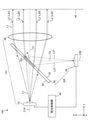
- FIG. 1 is a side view schematically showing a main configuration of the headlight device 100 according to the first embodiment.
- FIG. 2 is a plan view schematically showing a main configuration of the headlight device 100 according to the first embodiment.
- FIG. 3 is a perspective view schematically showing a main configuration of the headlight device 100 according to the first embodiment.
- the headlight device 100 is also referred to as a “headlight module”.
- the headlight device 100 may have a plurality of headlight modules.
- the headlight device 100 includes a light source unit 10, a light receiving unit 20, and a beam splitter 30 as a first optical unit.
- the configuration of the headlight device 100 is not limited to the configuration shown in FIGS. 1 to 3, and may be the configuration shown in FIGS. 6 to 11 described later.
- the light source unit 10 is one of the members constituting the projection optical system 101 of the headlight device 100.
- the projection optical system 101 has an optical axis C1 which is a first optical axis, and emits light L1 which is the first light in a predetermined emission direction.
- the emission direction is the + z-axis direction, which is the direction along the optical axis C1.
- the configuration of the light source unit 10 will be described later.
- the light receiving unit 20 and the beam splitter 30 are members constituting the imaging optical system 102.
- the light receiving unit 20 is a photodetection unit that detects the incident light L2 which is the second light traveling in the incident direction (in the first embodiment, the ⁇ z axis direction) which is the opposite direction of the emission direction.
- the optical axis of the light receiving unit 20 is indicated by the optical axis C20. The configuration of the light receiving unit 20 will be described later.
- the beam splitter 30 emits the light L1 in the emission direction and guides the incident light L2 to the light receiving unit 20.
- the beam splitter 30 reflects the central luminous flux L20, which is a part of the incident light L2, and emits the light L21 toward the light receiving unit 20.
- the central luminous flux L20 is a luminous flux including the central ray of the incident light L2.
- the central luminous flux L20 may be said to be a light flux traveling on the optical axis C1 of the incident light L2 and in the vicinity of the optical axis C1 (hereinafter, also referred to as “paraxial region”).
- the central luminous flux L20 may include a light ray traveling parallel to the optical axis C1 and a light ray traveling non-parallel to the optical axis C1 in the paraxial region of the optical axis C1.
- the beam splitter 30 has a central portion 32a as a diaphragm portion.
- the central portion 32a is arranged on the optical axis C1 and makes the diameter of the light L21 smaller than the diameter of the incident light L2 when it is incident on the image pickup optical system 102 toward the light receiving unit 20 after passing through the image pickup optical system 102.
- the central portion 32a is formed at a position covering, for example, the region where the central luminous flux L20 reaches in the beam splitter 30.
- the other configurations of the beam splitter 30 will be described later.
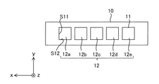
- FIG. 4 is a diagram showing the configuration of the light source unit 10 shown in FIGS. 1 to 3.
- FIG. 4 is a view of the light source unit 10 shown in FIGS. 1 to 3 as viewed from a position on the + z-axis side.
- the light source unit 10 may have, for example, a plurality of light emitting elements 11.
- the light emitting element 11 is a solid light source.
- the solid-state light source is a light source having directivity, and is, for example, a semiconductor light source such as a light emitting diode (LED).
- the light emitting element 11 may be an organic electroluminescence light source, or may be a light source that irradiates a phosphor with excitation light to emit the phosphor. It is desirable that the light emitting element 11 is an LED because it is small and easy to array, has high brightness, has little influence on the living body, and is low in cost.
- the light source unit 10 includes a single or a plurality of light emitting surfaces 12.
- the light source unit 10 includes, for example, N light emitting surfaces 12 arranged in a predetermined arrangement direction.
- N is a positive integer, and in the example shown in FIG. 4, N is 5.
- the arrangement direction of the plurality of light emitting surfaces 12 is the x-axis direction.
- the plurality of light emitting surfaces 12 are linearly arranged in a row.
- the plurality of light emitting surfaces 12 arranged in the x-axis direction are also referred to as 12a, 12b, 12c, 12d, and 12e. Further, as described above, the number of light emitting surfaces 12 provided in the light source unit 10 may be one. Further, the light source unit 10 may be provided with a configuration for adjusting light distribution, such as a movable light-shielding plate (not shown).
- the shape of the light emitting surface 12 when viewed in the z-axis direction is, for example, a rectangular shape.
- the length of the side S12 extending in the x-axis direction is the same as the length of the side S11 extending in the y-axis direction. That is, in FIG. 4, the shape of the light emitting surface 12 is a square.
- the shape of the light emitting surface 12 is not limited to a square, and may be another rectangular shape such as a rectangle, or may be another shape such as a circle.
- the headlight device 100 may have a lens as a second optical unit. That is, the headlight device 100 may have at least one lens. As shown in FIGS. 1 to 3, the headlight device 100 may have, for example, a projection / imaging combined lens 50.
- the projection / imaging combined lens 50 is arranged on the optical path of the light L1 traveling in the emission direction and on the optical path of the incident light L2 traveling in the incident direction. As shown in FIG. 6, which will be described later, the headlight device 100 can be realized even if the projection / imaging combined lens 50 is not provided.
- the projection / imaging combined lens 50 has a function of projecting the light L1 emitted from the light source unit 10 and a function of forming an image of the incident light L2 as the detection light incident from the outside on the light receiving unit 20.
- the projection / imaging combined lens 50 is, for example, a lens having a positive power.
- the projection / imaging combined lens 50 may be a spherical lens or an aspherical lens.
- the projection / imaging combined lens 50 is composed of one lens.
- the projection / imaging combined lens 50 may be composed of a lens group having a plurality of lenses. When the projection / imaging combined lens 50 is composed of a lens group, the light utilization efficiency decreases as the number of lenses increases.
- the projection / imaging combined lens 50 may be composed of two lenses. desirable. That is, it is desirable that the projection / imaging combined lens 50 is composed of one or two lenses.
- the projection / imaging combined lens 50 is formed of, for example, a transparent resin or the like.
- the second optical unit that projects the light L1 emitted from the light source unit 10 forward may be configured by a combination of a projection / imaging combined lens 50 and a reflection mirror.
- the light L1 incident on the projection / imaging combined lens 50 passes through the projection / imaging combined lens 50 and is emitted toward a predetermined irradiation region in front.
- the "predetermined irradiation region” is a predetermined region on the irradiation surface 90 arranged at a position on the + z-axis side of the projection / imaging combined lens 50.
- the irradiation surface 90 is a virtual projection surface on which the light distribution pattern of the light L1 is projected.
- the optical axis of the projection / imaging combined lens 50 is indicated by the optical axis C5
- the optical axis of the light source unit 10 is indicated by the optical axis C10.
- the optical axis C10 of the light source unit 10 and the optical axis C5 of the projection / imaging combined lens 50 are located on the same straight line. That is, the optical axis C10 and the optical axis C5 coincide with each other.
- the beam splitter 30 is an optical member that branches the optical path of the incident light L2 by reflecting a part of the incident light L2 incident from the outside on the light reflecting surface 32 having a predetermined reflectance.
- the beam splitter 30 may be configured by, for example, a dichroic mirror.
- the beam splitter 30 transmits the incident light L1 and emits it in the + z-axis direction.
- the light source unit 10 is arranged at a position on the ⁇ z axis side from the beam splitter 30. Therefore, the beam splitter 30 emits the light L1 incident from the ⁇ z axis side as illumination light in the emission direction (that is, the + z axis direction).
- the light receiving unit 20 is arranged at a position on the ⁇ y axis side from the beam splitter 30.
- the light receiving unit 20 may be arranged at a position on the + y-axis side of the beam splitter 30.
- the beam splitter 30 guides the incident light L2 incident through the projection / imaging combined lens 50 to the light receiving unit 20. Specifically, the beam splitter 30 emits the incident light L2 traveling in the incident direction (that is, the ⁇ z axis direction) as the light L21 traveling toward the light receiving unit 20.
- the beam splitter 30 has a light transmitting surface 33 that allows light L1 to pass through.
- the beam splitter 30 may have a property of transmitting light L1, that is, light transmission.
- the beam splitter 30 has a light reflecting surface 32 that reflects the incident light L2.
- the angle ⁇ of the light reflecting surface 32 with respect to the optical axis C1 is 45 degrees.
- the angle ⁇ is not limited to 45 degrees and may be another value.
- the incident light L2 reflected by the light reflecting surface 32 travels in the ⁇ y axis direction as the light L21 toward the light receiving unit 20.
- the light reflecting surface 32 and the light transmitting surface 33 are parallel to each other. As shown in FIG. 17, which will be described later, the light reflecting surface 32 and the light transmitting surface 33 may be non-parallel to each other.
- the light reflecting surface 32 of the beam splitter 30 has a central portion 32a as a diaphragm portion.
- the central portion 32a is arranged on the optical axis C1.
- the central portion 32a reflects the central luminous flux L20, which is a part of the incident light L2, and guides it to the light receiving portion 20.
- the light beam bundle of the light L21 incident on the light receiving unit 20 is composed of the light rays traveling in the paraxial region of the optical axis C1. That is, in the central portion 32a, the diameter of the light L21 that passes through the beam splitter 30 and travels toward the light receiving portion 20 is made smaller than the diameter of the incident light L2 when it is incident on the projection / imaging combined lens 50.
- the peripheral light ray L22 (see FIG. 1), which is a light ray traveling at a position away from the optical axis C1 of the incident light L2, to be incident on the light receiving unit 20, the image formed on the light receiving unit 20 is imaged. Aberration becomes smaller. Therefore, the detection accuracy of the incident light L2 in the light receiving unit 20 can be improved.
- the light reflecting surface 32 of the beam splitter 30 further has a peripheral portion 32b arranged outside the central portion 32a.
- the peripheral portion 32b transmits the light L1 and reflects the incident light L2.
- the reflectance of the peripheral portion 32b is smaller than the reflectance of the central portion 32a.
- the central portion 32a may be, for example, metal vapor deposition or a dielectric beam splitter coating.
- the peripheral portion 32b may be, for example, coated with an AR (Anti-Reflective) coating.
- the peripheral portion 32b may not be subjected to AR coating.
- the shape of the central portion 32a is, for example, a circle.
- the shape of the central portion 32a is not limited to a circular shape, and may be another shape.
- a plurality of reflecting regions having different reflectances may be continuously formed so that the reflectance smoothly increases as the light reflecting surface 32 approaches the optical axis C1 from the outer edge of the beam splitter 30.
- a plurality of reflecting regions may be discretely formed so that the reflectance gradually increases as the light reflecting surface 32 approaches the optical axis C1 from the outer edge of the beam splitter 30. From the viewpoint of effectively guiding the incident light L2 traveling in the vicinity of the optical axis C1 to the light receiving unit 20, the light reflecting surfaces 32 have different reflectances so that the reflectance smoothly increases as the optical axis C1 approaches. A configuration in which a plurality of reflection regions are continuously formed is desirable.
- the light receiving unit 20 is arranged between the light source unit 10 and the projection / imaging combined lens 50 in the z-axis direction.
- the light receiving unit 20 detects the incident light L2 that is emitted from a predetermined light receiving region in front of the light receiving unit 20 and is incident via the projection / imaging combined lens 50 and the beam splitter 30.
- the incident light L2 is the detection light detected by the light receiving unit 20.
- the "predetermined light receiving region" is a predetermined region existing at a position on the + z axis side of the projection / imaging combined lens 50, and includes at least the above-mentioned "predetermined irradiation region". ..
- the incident light L2 may be the light emitted from the object.
- the incident light L2 may be light emitted from the headlight of the oncoming vehicle.
- the incident light L2 may be the light emitted from the taillight of the preceding vehicle.
- the incident light L2 may be the light reflected by the object.
- the incident light L2 is reflected by the pedestrian, the road surface, or the guardrail. It may be light.
- the object to be the emission point of the incident light L2 is an arbitrary object (road surface, oncoming vehicle, preceding vehicle, pedestrian, etc.) located on the + z-axis side of the projection / imaging combined lens 50.
- FIG. 5 is a diagram showing the configuration of the light receiving unit 20 shown in FIGS. 1 to 3.
- FIG. 5 is a view of the light receiving portion 20 shown in FIGS. 1 to 3 as viewed from the position on the ⁇ y axis side.
- the light receiving unit 20 has a plurality of light receiving elements 21.
- the light receiving element 21 is, for example, a semiconductor element that converts the energy of the received light L21 into an electric signal.
- the light receiving element 21 is, for example, a photodiode, a CCD (Charge Coupled Device) image sensor, a CMOS (Complementary Metal Oxide Semiconductor) image sensor, or the like.
- the light receiving unit 20 may be a line sensor including a plurality of light receiving elements 21. In the following description, the surface of the light receiving element 21 facing the ⁇ y axis direction is referred to as a light receiving surface 22.
- the light receiving unit 20 includes a plurality of light receiving surfaces 22 arranged in the x-axis direction.
- the plurality of light receiving surfaces 22 arranged in the z-axis direction are also referred to as 22a, 22b, 22c, 22d, and 22e.
- the light receiving unit 20 includes M light receiving surfaces 22 arranged in a direction corresponding to the arrangement direction of the plurality of light emitting surfaces 12 (see FIG. 4). M is a positive integer, and in the example shown in FIG. 5, M is 5.
- the "direction corresponding to the arrangement direction of the plurality of light emitting surfaces 12" is a direction parallel to the arrangement direction of the plurality of light emitting surfaces 12 and a direction inclined rather than parallel to the arrangement direction of the plurality of light emitting surfaces 12. It means to include.
- the plurality of light receiving surfaces 22 are arranged in the x-axis direction parallel to the arrangement direction of the plurality of light emitting surfaces 12.
- the number M of the plurality of light receiving surfaces 22 is equal to the number N of the plurality of light emitting surfaces 12 shown in FIG. Therefore, in the first embodiment, the plurality of light receiving surfaces 22 and the plurality of light emitting surfaces 12 have a one-to-one correspondence.
- the plurality of light receiving surfaces 22 may be arranged in a straight line, for example.
- the shape of the light receiving surface 22 when viewed in the y-axis direction is, for example, a rectangular shape.
- the length of the side S21 extending in the z-axis direction is longer than the length of the side S22 extending in the x-axis direction. That is, in FIG. 5, the shape of the light receiving surface 22 is a rectangle.
- a margin can be provided in the vertical direction (that is, the z-axis direction) of the light receiving surface 22, and a moving body (for example, another vehicle or a pedestrian) located in front of the light receiving surface 22 can be accurately detected.
- the shape of the light receiving surface 22 is not limited to a rectangle, and may be another rectangular shape such as a square. Further, the shape of the light receiving surface 22 is not limited to a rectangular shape, and may be another shape such as a circular shape.
- the headlight device 100 further includes a light distribution control unit 40 connected to the light source unit 10 and the light receiving unit 20.
- the light distribution control unit 40 causes the light source unit 10 to adjust the light distribution pattern of the light L1 based on the detection signal corresponding to the light L21 detected by the light receiving unit 20.
- the light distribution control unit 40 determines, for example, whether or not the intensity of the light L21 detected on each of the plurality of light receiving surfaces 22 (see FIG. 5) is equal to or higher than a predetermined threshold value. Then, when the light distribution control unit 40 determines that the intensity of the light L21 detected on at least one light receiving surface (for example, the light receiving surface 22c shown in FIG. 5) among the plurality of light receiving surfaces 22 is equal to or higher than the threshold value. , Controls the light emitting surface 12 (see FIG. 4) of the light source unit 10.
- the light distribution control unit 40 turns off the light emitting surface 12c corresponding to the light receiving surface 22c in which the light L21 having an intensity equal to or higher than the threshold value is detected among the plurality of light emitting surfaces 12, and the other light emitting surface. Control is performed to light 12a, 12b, 12d, and 12e. As a result, the light source unit 10 can adjust the light distribution pattern of the light L1. In the first embodiment, the detection accuracy of the light L21 in the light receiving unit 20 is improved. Therefore, the light distribution pattern of the light L1 is accurately irradiated to the target irradiation region, and the visibility of the driver of the vehicle equipped with the headlight device 100 can be satisfactorily secured.
- the light distribution control unit 40 is, for example, a control circuit composed of a semiconductor integrated circuit.
- the light distribution control unit 40 may be configured by a processor that executes a program stored in the memory.
- the light source unit 10 the beam splitter 30, and the projection / imaging combined lens 50 are projection optics as a first optical system that irradiates light L1 as illumination light in front of a vehicle provided with a headlight module. It constitutes a system 101.
- the light L1 emitted from the light source unit 10 passes through the beam splitter 30 and is irradiated to the front of the vehicle by the projection / imaging combined lens 50.
- the projection / imaging combined lens 50, the beam splitter 30, and the light receiving unit 20 constitute an imaging optical system 102 as a second optical system for imaging the front of the vehicle.
- the incident light L2 incident from the outside through the projection / imaging combined lens 50 is reflected by the beam splitter 30 and imaged on the light receiving surface 22 of the light receiving unit 20.
- the image pickup optical system 102 has an optical axis C2 which is a second optical axis.
- the projection optical system 101 and the image pickup optical system 102 share the beam splitter 30 and the projection / image pickup lens 50. That is, the projection optical system 101 and the imaging optical system 102 have a common optical axis C5 in front of the beam splitter 30. Therefore, a part of the optical axis C1 of the projection optical system 101 coincides with a part of the optical axis C2 of the image pickup optical system 102 in the emission direction.
- a part of the optical axis C1 of the projection optical system 101 is an image pickup optical in the emission direction (specifically, in front of the beam splitter 30). It coincides with a part of the optical axis C2 of the system 102. Therefore, in the headlight device 100, a step of adjusting the optical axis C1 of the projection optical system 101 and the optical axis C2 of the image pickup optical system 102 is unnecessary. Therefore, it becomes easy to match the irradiation range of the light L1 emitted from the headlight device 100 with the incident range of the incident light L2 incident on the headlight device 100.
- the imaging optical system 102 of the headlight device 100 has a beam splitter 30.
- the beam splitter 30 has a central portion 32a as a diaphragm portion, and the central portion 32a captures the diameter of the light L21 that passes through the imaging optical system 102 (that is, the beam splitter 30) and travels toward the light receiving portion 20. It is smaller than the diameter of the incident light L2 when it is incident on the optical system 102 (that is, the projection / imaging combined lens 50).
- the peripheral light ray L22 traveling at a position away from the optical axis C1 of the incident light L2 to be incident on the light receiving unit 20. Therefore, since the aberration of the image formed on the light receiving unit 20 is reduced, the detection accuracy of the incident light L2 in the light receiving unit 20 can be improved.
- the projection / imaging combined lens 50 is shared in the projection optical system 101 and the image pickup optical system 102. Thereby, the design of the headlight device 100 can be improved.
- FIG. 6 is a side view schematically showing a main configuration of the headlight device 100a according to the first modification of the first embodiment.
- the same or corresponding components as those shown in FIG. 1 are designated by the same reference numerals as those shown in FIG.
- the headlight device 100a has a light source unit 10, a light receiving unit 20, and a beam splitter 30.
- the projection optical system 101a is composed of a light source unit 10 and a beam splitter 30. Therefore, in the example shown in FIG. 6, the light L1 emitted from the light source unit 10 is projected forward after passing through the beam splitter 30.
- the imaging optical system 102a is composed of a beam splitter 30 and a light receiving unit 20. Therefore, in the example shown in FIG. 6, the incident light L2 from the outside is reflected by the beam splitter 30 and then heads toward the light receiving unit 20.
- the beam splitter 30 and the projection / image pickup lens 50 are shared in the projection optical system 101a and the image pickup optical system 102a of the headlight device 100a. That is, a part of the optical axis C1 of the projection optical system 101a coincides with a part of the optical axis C2 of the image pickup optical system 102a in the emission direction (specifically, in front of the beam splitter 30). Therefore, in the headlight device 100a, the step of adjusting the optical axis C1 of the projection optical system 101a and the optical axis C2 of the image pickup optical system 102a is unnecessary. This makes it easy to match the irradiation range of the light L1 emitted from the headlight device 100a with the incident range of the incident light L2 incident on the headlight device 100a.
- the central portion 32a determines the diameter of the light L21 that passes through the imaging optical system 102a (that is, the beam splitter 30) and advances toward the light receiving unit 20. It is made smaller than the diameter of the incident light L2 when it is incident on 102a (that is, the projection / imaging combined lens 50). As a result, it becomes difficult for the peripheral light ray L22 traveling at a position away from the optical axis C1 of the incident light L2 to be incident on the light receiving unit 20. Therefore, since the aberration of the image formed on the light receiving unit 20 is reduced, the detection accuracy of the incident light L2 in the light receiving unit 20 can be improved.
- the projection optical system 101a of the headlight device 100a is composed of a light source unit 10 and a beam splitter 30, and the image pickup optical system 102a is a beam splitter 30 and a light receiving unit 20. Consists of.
- the number of members constituting the projection optical system 101a and the image pickup optical system 102a is smaller than that in the headlight device 100 according to the first embodiment, so that the headlight device 100a is used. It can be miniaturized.
- FIG. 7 is a side view schematically showing a main configuration of the headlight device 100b according to the second modification of the first embodiment.
- components that are the same as or correspond to the components shown in FIG. 1 are designated by the same reference numerals as those shown in FIG.
- the headlight device 100b includes a light source unit 10, a light receiving unit 20, a beam splitter 30, a projection / imaging combined lens 50 as a first optical member, and a second optical member.
- the headlight device 100b has a plurality of lenses (that is, a projection / imaging combined lens 50 and a condenser lens 60) as a second optical unit.
- the projection optical system 101b is composed of a light source unit 10, a beam splitter 30, a projection / imaging combined lens 50, and a condenser lens 60.
- the condenser lens 60 is arranged on the optical path of the light L1 emitted from the light source unit 10 and directed toward the beam splitter 30.
- the condenser lens 60 is arranged between the light source unit 10 and the beam splitter 30.
- the condenser lens 60 has a function of condensing the light L1 emitted from the light source unit 10 and directing it to the beam splitter 30.
- the condenser lens 60 can change the light distribution pattern of the incident light L1. That is, the condenser lens 60 is a light distribution changing lens that changes the light distribution pattern of the light L1.
- the projection optical system 101b has one condenser lens 60.
- the projection optical system 101b may have a plurality of condenser lenses 60. That is, the projection optical system 101b may have one or more condenser lenses 60.
- the second optical member that guides the light L1 emitted from the light source unit 10 to the beam splitter 30 may be configured by a combination of a condenser lens 60 and a reflection mirror.
- the optical axis of the condenser lens 60 is indicated by C6.
- the optical axis C10 of the light source unit 10 and the optical axis C6 of the condenser lens 60 are located on the same straight line. That is, the optical axis C10 and the optical axis C6 coincide with each other.
- the headlight device 100b can be realized even if the optical axis C10 and the optical axis C6 do not match.
- the condenser lens 60 has, for example, a rotationally symmetric shape with the optical axis C6 as the axis of rotation.
- the condenser lens 60 may be a lens having a rotationally asymmetrical shape.
- the condenser lens 60 is, for example, an aspherical lens.
- the sag amount on the surface of the condenser lens 60 may be different from each other in the x-axis direction and the y-axis direction. Further, the sag amount on the + y-axis side of the optical axis C6 and the sag amount on the ⁇ y-axis side of the optical axis C6 may be different from each other.
- the surface of the condenser lens 60 may be a free curved surface. Further, the surface of the condenser lens 60 may be eccentric with respect to the optical axis C6. Further, the surface of the condenser lens 60 may be inclined in the y-axis direction with respect to the direction perpendicular to the optical axis C6.
- the condenser lens 60 is made of, for example, a plastic material such as a PC (Polycarbonate) resin or a glass material.
- a plastic material such as a PC (Polycarbonate) resin or a glass material.
- FIG. 7 an example in which the headlight device 100b has a projection / image pickup lens 50 has been described, but the headlight device 100b can be realized even if the headlight device 100b does not have the projection / image pickup lens 50. can.
- the beam splitter 30 and the projection / image pickup lens 50 are shared in the projection optical system 101b and the image pickup optical system 102 of the headlight device 100b. That is, a part of the optical axis C1 of the projection optical system 101b coincides with a part of the optical axis C2 of the image pickup optical system 102 in the emission direction (specifically, in front of the beam splitter 30). Therefore, in the headlight device 100b, the step of adjusting the optical axis C1 of the projection optical system 101b and the optical axis C2 of the image pickup optical system 102 is unnecessary. This makes it easy to match the irradiation range of the light L1 emitted from the headlight device 100b with the incident range of the incident light L2 incident on the headlight device 100b.
- the central portion 32a determines the diameter of the light L21 that passes through the imaging optical system 102 (that is, the beam splitter 30) and advances toward the light receiving unit 20. It is smaller than the diameter of the incident light L2 when it is incident on 102 (that is, the projection / imaging combined lens 50). As a result, it becomes difficult for the peripheral light ray L22 traveling at a position away from the optical axis C1 of the incident light L2 to be incident on the light receiving unit 20. Therefore, since the aberration of the image formed on the light receiving unit 20 is reduced, the detection accuracy of the incident light L2 in the light receiving unit 20 can be improved.
- the projection optical system 101b of the headlight device 100b is a condenser lens arranged on the optical path of the light L1 emitted from the light source unit 10 and directed toward the beam splitter 30. Has 60.
- the light L1 can be projected forward after the light distribution pattern of the light L1 is changed by the condenser lens 60. Therefore, the degree of freedom in designing the light distribution pattern of the light L1 can be improved.
- FIG. 8 is a side view schematically showing a main configuration of the headlight device 100c according to the third modification of the first embodiment.
- components that are the same as or correspond to the components shown in FIG. 1 are designated by the same reference numerals as those shown in FIG.
- the headlight device 100c includes a light source unit 10, a light receiving unit 20, a beam splitter 30, a projection / imaging combined lens 50 as a first optical member, and a third optical member.
- the headlight device 100b has a plurality of lenses (that is, a projection / imaging combined lens 50 and an image pickup lens 70) as a second optical unit.
- the imaging optical system 102c is configured by the projection / imaging combined lens 50, the beam splitter 30, the imaging lens 70, and the light receiving unit 20.
- the image pickup lens 70 is arranged on the optical path of the light L21 that passes through the beam splitter 30 and heads toward the light receiving unit 20. In the example shown in FIG. 8, the image pickup lens 70 is arranged between the beam splitter 30 and the light receiving unit 20.
- the image pickup lens 70 has a function of forming an image of the light L21 reflected by the beam splitter 30 on the light receiving unit 20.
- the image pickup lens 70 may be a spherical lens or an aspherical lens.
- the optical axis of the image pickup lens 70 is indicated by C7.
- the optical axis C7 coincides with the optical axis C5 of the projection / imaging combined lens 50 on the + z-axis side of the beam splitter 30.
- the optical axis C7 and the optical axis C5 are aligned with each other, it is easy to guide the central luminous flux L20 traveling on the optical axis C1 of the incident light L2 to the light receiving unit 20. Therefore, the aberration of the image formed on the light receiving unit 20 is reduced, and the detection accuracy of the incident light L2 in the light receiving unit 20 can be improved.
- the image pickup lens 70 is formed of, for example, a plastic material such as PMMA (Polymethyl methyllate) resin or a glass material.
- a plastic material such as PMMA (Polymethyl methyllate) resin or a glass material.
- the third optical member that guides the incident light L2 reflected by the beam splitter 30 to the light receiving unit 20 may be configured by a combination of an image pickup lens 70 and a reflection mirror.
- the beam splitter 30 is arranged between the projection / imaging combined lens 50 and the imaging lens 70.
- the beam splitter 30 has the same effect as the diaphragm provided inside the general image pickup optical system.
- the beam splitter 30 can limit the light incident on the light receiving unit 20 to the central luminous flux L20 traveling on the optical axis C1 and in the vicinity of the optical axis C1, that is, in the paraxial region. Therefore, it is possible to prevent vignetting of light rays in the image formed on the light receiving unit 20. Therefore, it is possible to reduce limb darkening on the light receiving surface of the light receiving unit 20.
- the imaging optical system 102c is a symmetric optical system centered on a plane including the light reflecting surface 32 of the beam splitter 30, or an optical system similar to the symmetric optical system. This makes it possible to reduce distortion in the image formed on the light receiving unit 20. Therefore, limb darkening on the light receiving surface of the light receiving unit 20 can be reduced.
- FIG. 8 an example in which the headlight device 100c has a projection / image pickup lens 50 has been described, but the headlight device 100c can be realized even if the headlight device 100c does not have the projection / image pickup lens 50. be able to.
- the beam splitter 30 and the projection / image pickup lens 50 are shared in the projection optical system 101 and the image pickup optical system 102c of the headlight device 100c. That is, a part of the optical axis C1 of the projection optical system 101 coincides with a part of the optical axis C2 of the image pickup optical system 102c in the emission direction (specifically, in front of the beam splitter 30). Therefore, in the headlight device 100c, the step of adjusting the optical axis C1 of the projection optical system 101 and the optical axis C2 of the image pickup optical system 102c is unnecessary. This makes it easy to match the irradiation range of the light L1 emitted from the headlight device 100c with the incident range of the incident light L2 incident on the headlight device 100c.
- the central portion 32a determines the diameter of the light L21 that passes through the imaging optical system 102c (that is, the beam splitter 30) and advances toward the light receiving unit 20. It is made smaller than the diameter of the incident light L2 when it is incident on 102d (that is, the projection / imaging combined lens 50). Peripheral light rays L22 traveling at a position away from the optical axis C1 of the incident light L2 are less likely to be incident on the light receiving unit 20. Therefore, the aberration of the image formed on the light receiving unit 20 is reduced. Therefore, the detection accuracy of the incident light L2 in the light receiving unit 20 can be improved.
- the image pickup optical system 102c of the headlight device 100c is an image pickup lens 70 arranged on the optical path of the light L21 which passes through the beam splitter 30 and heads toward the light receiving unit 20. Has. As a result, the number of optical surfaces that control the light L21 incident on the light receiving unit 20 increases. Therefore, the degree of freedom in designing the imaging optical system 102c can be improved.
- FIG. 9 is a side view schematically showing a main configuration of the headlight device 100d according to the fourth modification of the first embodiment.
- components that are the same as or correspond to the components shown in FIG. 1 are designated by the same reference numerals as those shown in FIG.
- the headlight device 100d includes a light source unit 10, a light receiving unit 20, a beam splitter 30, a projection / imaging combined lens 50, a condenser lens 60, and an image pickup lens 70. ..
- the projection optical system 101d is configured by the light source unit 10, the condenser lens 60, the beam splitter 30, and the projection / imaging combined lens 50.
- the imaging optical system 102d is configured by the projection / imaging combined lens 50, the beam splitter 30, the imaging lens 70, and the light receiving unit 20. That is, the beam splitter 30 and the projection / imaging combined lens 50 are shared in the projection optical system 101d and the imaging optical system 102d of the headlight device 100d.
- the beam splitter 30 and the projection / image pickup lens 50 are shared in the projection optical system 101d and the image pickup optical system 102d of the headlight device 100d. That is, a part of the optical axis C1 of the projection optical system 101 coincides with a part of the optical axis C2 of the image pickup optical system 102 in the emission direction (specifically, in front of the beam splitter 30). Therefore, in the headlight device 100d, the step of adjusting the optical axis C1 of the projection optical system 101d and the optical axis C2 of the image pickup optical system 102d is unnecessary. This makes it easy to match the irradiation range of the light L1 emitted from the headlight device 100d with the incident range of the incident light L2 incident on the headlight device 100d.
- the central portion 32a has the diameter of the optical L21 that passes through the imaging optical system 102d (that is, the beam splitter 30) and advances toward the light receiving unit 20. It is made smaller than the diameter of the incident light L2 when it is incident on 102d (that is, the projection / imaging combined lens 50). Peripheral light rays L22 traveling at a position away from the optical axis C1 of the incident light L2 are less likely to be incident on the light receiving unit 20. Therefore, the aberration of the image formed on the light receiving unit 20 is reduced. Therefore, the detection accuracy of the incident light L2 in the light receiving unit 20 can be improved.
- the projection optical system 101d has a condenser lens 60 arranged on the optical path of the light L1 emitted from the light source unit 10 and directed toward the beam splitter 30 for imaging.
- the optical system 102d has an image pickup lens 70 arranged on the optical path of the light L21 that passes through the beam splitter 30 and heads toward the light receiving unit 20.
- FIG. 10 is a perspective view schematically showing a main configuration of the headlight device 100e according to the fifth modification of the first embodiment.
- components that are the same as or correspond to the components shown in FIG. 3 are designated by the same reference numerals as those shown in FIG.
- the headlight device 100e includes a light source unit 10, a light receiving unit 20, a beam splitter 30e, and a projection / imaging combined lens 50.
- the projection optical system 101e is configured by the light source unit 10, the beam splitter 30e, and the projection / imaging combined lens 50, and the imaging optics are formed by the projection / imaging combined lens 50, the beam splitter 30e, and the light receiving unit 20.
- the system 102e is configured.
- the projection optical system 101e and the imaging optical system 102e share the beam splitter 30e and the projection / imaging combined lens 50. Therefore, the projection optical system 101e and the image pickup optical system 102e have a common optical axis C5. That is, a part of the optical axis C1 of the projection optical system 101e coincides with a part of the optical axis C2 of the image pickup optical system 102e in the emission direction. This makes it easy to match the irradiation range of the light L1 emitted from the headlight device 100 with the incident range of the incident light L2 incident on the headlight device 100.
- the beam splitter 30e has a central portion 32e as a diaphragm portion arranged on the optical axis C1.
- the central portion 32e reflects a part of the incident light L2 traveling in the incident direction (that is, the central luminous flux L20) and guides it to the light receiving portion 20. That is, the central portion 32e is a light reflecting portion that reflects the central luminous flux L20 traveling in the paraxial region of the incident light L2.
- the shape of the central portion 32e is, for example, a circle.
- the shape of the central portion 32a may be an ellipse or another shape.
- the diameter of the central portion 32e is smaller than the diameter of the incident light L2 when it is incident on the imaging optical system 102e.
- the light L1 emitted from the light source unit 10 passes through the central portion 32e and also passes through the region outside the beam splitter 30e.
- a part of the optical axis C1 of the projection optical system 101e is imaged in the emission direction (that is, in front of the beam splitter 30). It coincides with a part of the optical axis C2 of the optical system 102e. Therefore, in the headlight device 100e, the step of adjusting the optical axis C1 of the projection optical system 101e and the optical axis C2 of the image pickup optical system 102e is unnecessary. Therefore, it becomes easy to match the irradiation range of the light L1 emitted from the headlight device 100 with the incident range of the incident light L2 incident on the headlight device 100.
- the imaging optical system 102 of the headlight device 100e has a beam splitter 30e that reflects a part of the incident light L2 and guides it to the light receiving unit 20.
- the splitter 30e has a central portion 32e as a throttle portion.
- the central portion 32e guides the central luminous flux L20 of the incident light L2 to the light receiving portion, and the incident when the diameter of the light L21 that passes through the imaging optical system 102e and travels toward the light receiving portion 20 is incident on the imaging optical system 102e. Make it smaller than the diameter of the optical L2.
- FIG. 11 is a perspective view schematically showing a main configuration of the headlight device 100f according to the sixth modification of the first embodiment.
- components that are the same as or correspond to the components shown in FIG. 3 are designated by the same reference numerals as those shown in FIG.
- the headlight device 100f includes a light source unit 10, a light receiving unit 20, a first optical unit 30f, and a projection / imaging combined lens 50.
- the first optical unit 30f has a beam splitter 31 and a light-shielding plate 35 as a diaphragm unit.
- the beam splitter 31 is arranged on the optical axis C1.
- the beam splitter 31 reflects a part of the incident light L2 traveling in the incident direction and directs it toward the light shielding plate 35.
- the projection optical system 101f is configured by the light source unit 10, the beam splitter 31, and the projection / imaging combined lens 50.
- the imaging optical system 102f is configured by the projection / imaging combined lens 50, the beam splitter 31, the light shielding plate 35, and the light receiving unit 20.
- the projection optical system 101f and the imaging optical system 102f share the beam splitter 31 and the projection / imaging combined lens 50. Therefore, the projection optical system 101f and the imaging optical system 102f have a common optical axis C5 in front of the beam splitter 31. That is, a part of the optical axis C1 of the projection optical system 101f coincides with a part of the optical axis C2 of the image pickup optical system 102f in the emission direction. This makes it easy to match the irradiation range of the light L1 emitted from the headlight device 100 with the incident range of the incident light L2 incident on the headlight device 100.
- the light-shielding plate 35 is a light-shielding member arranged between the beam splitter 31 and the light-receiving unit 20 in the y-axis direction.
- the light-shielding plate 35 has an opening 35a as a diaphragm portion.
- the portion other than the opening 35a is a light-shielding portion 35b that shields the peripheral light L22 of the incident light L2 reflected by the beam splitter 31.
- the opening 35a is located on the optical axis C20 of the light receiving unit 20.
- the opening 35a passes the central luminous flux L20, which is a part of the incident light L2 reflected by the beam splitter 31 and directed toward the light receiving unit 20, as the light L21.
- the aperture 35a is smaller than the diameter of the incident light L2 when it is incident on the imaging optical system 102f (that is, the projection / imaging combined lens 50).
- the aperture 35a causes the image pickup optical system 102 (that is, the projection / image pickup lens 50) to have the diameter of the light L21 that passes through the image pickup optical system 102f (that is, the light shielding plate 35) and travels toward the light receiving unit 20.
- the light-shielding plate 35 is arranged not only between the beam splitter 31 and the light receiving unit 20, but also on the + z-axis side of the beam splitter 31 (for example, between the beam splitter 31 and the projection / imaging lens 50). It is also good. Further, when the headlight device 100f has the image pickup lens 70 shown in FIG. 8 or 9, the light shielding plate 35 may be provided in the vicinity of the image pickup lens 70 or the image pickup lens 70.
- a part of the optical axis C1 of the projection optical system 101f is in the emission direction (specifically, in front of the beam splitter 31). Consistent with a part of the optical axis C2 of the imaging optical system 102f. Therefore, in the headlight device 100f, the step of adjusting the optical axis C1 of the projection optical system 101f and the optical axis C2 of the image pickup optical system 102f is unnecessary. Therefore, it becomes easy to match the irradiation range of the light L1 emitted from the headlight device 100f with the incident range of the incident light L2 incident on the headlight device 100f.
- the image pickup optical system 102f of the headlight device 100f has a light-shielding plate 35 as a diaphragm portion having an opening 35a, and the opening 35a is the image pickup optical system 102f. It is smaller than the diameter of the incident light L2 when it is incident on.
- the aperture 35a makes the diameter of the light L21 that passes through the image pickup optical system 102f and travels toward the light receiving unit 20 smaller than the diameter of the incident light L2 when it is incident on the image pickup optical system 102f. Therefore, it becomes difficult for the peripheral light ray L22 traveling at a position away from the optical axis C1 of the incident light L2 to be incident on the light receiving unit 20. Therefore, since the aberration of the image formed on the light receiving unit 20 is small, the detection accuracy of the incident light L2 in the light receiving unit 20 can be improved.
- Embodiment 2 >> In the first embodiment, an example in which the light reflected by the central portion 32a of the beam splitter 30 of the incident light L2 is incident on the light receiving portion 20 has been described. In the second embodiment, an example of defining the area and the reflectance of the central portion 32a will be described. Other than this, the headlight device according to the second embodiment is the same as the headlight device 100 according to the first embodiment. Therefore, in the following description, FIGS. 1 to 3 will be referred to.
- the area of the central portion 32a is 20% or less of the area of the light reflecting surface 32. That is, the light bundle of the light L21 when it is incident on the light receiving unit 20 is the light bundle of the incident light L2 when it is incident on the imaging optical system 102 (in the example shown in FIGS. 1 to 3, the projection / imaging combined lens 50). It is limited to 20% or less of the effective cross-sectional area. As a result, the aberration of the image formed on the light receiving surface of the light receiving unit 20 can be reduced as compared with the configuration in which the beam splitter is a half-miller. Further, when the beam splitter is a half mirror, the illumination light transmitted through the optical member and the incident light reflected by the optical member are uniform.
- the maximum luminous intensity of the light L1 transmitted through the beam splitter 30 can be equal to or higher than the maximum luminous intensity of the illumination light transmitted through the half mirror.
- the reflectance of the central portion 32a is larger than 50% and 100% or less.
- the central luminous flux L20 traveling in the paraxial region of the optical axis C1 of the incident light L2 is the light receiving portion as compared with the configuration in which the entire beam splitter is a half mirror. It becomes easy to be incident on 20.
- FIG. 12 is a diagram showing an example of a spot diagram of light incident on the light receiving unit 20 of the headlight device according to the second embodiment.
- the spot diagram shown in FIG. 12 is a spot diagram at the intersection of the light receiving surface 22 (see FIG. 5) and the optical axis C20 of the light receiving unit 20.
- the RMS (Root Mean Square) radius indicating the spot size which is the distribution of the intersections of the light L21 and the light receiving surface 22 of the light receiving unit 20, is 15.338 ⁇ m.
- FIG. 13 is a diagram showing an example of a spot diagram of light incident on the light receiving portion of the headlight device according to the comparative example.
- the headlight device according to the comparative example is different from the headlight device according to the second embodiment in that the optical member is a half mirror.
- the spot diagram shown in FIG. 13 is a spot diagram in which the incident angle of the light ray with respect to the optical axis of the light receiving portion is 0 degree and the light receiving surface 22 is at the center position.
- the RMS radius indicating the spot size of light is 1451.20 ⁇ m.
- the spot size of the image can be reduced.
- the spot size (area) in the headlight device according to the second embodiment is, for example, about 14% when the area of the light reflecting surface 32 is a circle of 20%.
- the spot size (area) in the headlight device according to the second embodiment is considered to be smaller than about 14%.
- the area of the central portion 32a is 20% or less of the area of the light reflecting surface 32, and the reflectance of the central portion 32a is larger than 50% and 100% or less. ..
- the aberration of the image formed on the light receiving unit 20 can be reduced, and the detection accuracy of the incident light L2 in the light receiving unit 20 can be improved.
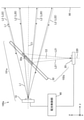
- FIG. 14 is a perspective view schematically showing a main configuration of the headlight device 300 according to the third embodiment.
- components that are the same as or correspond to the components shown in FIG. 1 are designated by the same reference numerals as those shown in FIG.
- the headlight device 300 includes a light source unit 310, a light receiving unit 320, a beam splitter 330 as a first optical unit, and a projection / imaging combined lens 50.
- the beam splitter 330 is arranged on the optical axis C1.
- the projection optical system 301 is configured by the light source unit 10, the beam splitter 330, and the projection / imaging combined lens 50
- the imaging optical system 302 is formed by the projection / imaging combined lens 50, the beam splitter 330, and the light receiving unit 320. It is composed.
- the projection optical system 301 and the imaging optical system 302 share the beam splitter 330 and the projection / imaging combined lens 50. Therefore, the projection optical system 301 and the imaging optical system 302 have a common optical axis C5 in front of the beam splitter 330. That is, a part of the optical axis C1 of the projection optical system 301 coincides with a part of the optical axis C2 of the image pickup optical system 302 in the emission direction.
- the headlight device 300 does not require a step of adjusting the optical axis C1 of the projection optical system 301 and the optical axis C2 of the image pickup optical system 302. Therefore, it becomes easy to match the irradiation range of the light L1 emitted from the headlight device 300 with the incident range of the incident light L2 incident on the headlight device 300.
- the light source unit 310 is arranged at a position on the ⁇ y axis side from the beam splitter 330.
- the beam splitter 330 reflects the light L1 incident from the ⁇ y axis side and emits it as the light L3 to the + z axis side.
- the light source unit 310 may be arranged at a position on the + y-axis side of the beam splitter 330.
- the light receiving unit 320 is arranged at a position on the ⁇ z axis side from the beam splitter 330.
- the beam splitter 330 transmits the incident light L2 incident through the projection / imaging lens 50 and guides it to the light receiving unit 320. That is, in the third embodiment, the beam splitter 330 reflects the light L1 and emits it in the exit direction, and transmits the incident light L2 to guide the light receiving unit 320.
- the beam splitter 330 has a light reflecting surface 332 that reflects the light L1 and transmits the incident light L2.
- the light reflecting surface 332 has a central portion 332a as a diaphragm portion.
- the central portion 332a is arranged on the optical axis C1.
- the central portion 332a is a light transmitting portion that transmits the central luminous flux L20 traveling in the paraxial region of the incident light L2 and guides it to the light receiving portion 320.
- the central luminous flux L20 transmitted through the central portion 332a travels in the ⁇ z axis direction as the light L21 traveling toward the light receiving portion 320.
- the central portion 332a guides the central luminous flux L20 to the light receiving unit 320, and the diameter of the light L21 that passes through the image pickup optical system 302 and travels toward the light receiving unit 320 is larger than the diameter of the incident light L2 when it is incident on the image pickup optical system 102. Make it smaller. As a result, it becomes difficult for the peripheral light ray L22 traveling at a position away from the optical axis C1 of the incident light L2 to be incident on the light receiving unit 320. Therefore, since the aberration of the image formed on the light receiving unit 320 is reduced, the detection accuracy of the incident light L2 in the light receiving unit 320 can be improved.
- the light reflecting surface 332 is arranged outside the central portion 332a and further has a peripheral portion 332b that reflects the light L1.
- the reflectance of the peripheral portion 332b is larger than the reflectance of the central portion 332a.
- the peripheral light ray L22 traveling at a position away from the optical axis C1 of the incident light L2 is reflected by the peripheral portion 332b. That is, since the peripheral ray L22 of the incident light L2 is less likely to pass through the beam splitter 330, the peripheral ray L22 is less likely to be incident on the light receiving unit 320. Therefore, since the aberration of the image formed on the light receiving unit 320 is reduced, the detection accuracy of the incident light L2 in the light receiving unit 320 can be further improved.
- AR coating may be applied to the central portion 332a.
- the central portion 332a may not be subjected to AR coating.
- the peripheral portion 332b may be provided with, for example, metal vapor deposition or a dielectric beam splitter coating.
- the shape of the central portion 332a is, for example, a circle.
- the shape of the central portion 332a is not limited to a circular shape, and may be another shape.
- a plurality of reflecting regions having different reflectances may be continuously formed so that the reflectance smoothly decreases as the light reflecting surface 332 approaches the optical axis C1 from the outer edge of the beam splitter 330.
- a plurality of reflection regions may be discretely formed on the light reflection surface 332 so that the reflectance gradually decreases as the beam splitter 330 approaches the optical axis C1 from the outer edge. From the viewpoint of effectively guiding the incident light L2 traveling in the vicinity of the optical axis C1 to the light receiving unit 320, the light reflecting surfaces 332 have different reflectances so that the reflectance smoothly decreases as the optical axis C1 approaches. A configuration in which a plurality of reflection regions are continuously formed is desirable.
- a part of the optical axis C1 of the projection optical system 301 is an image pickup optical in the emission direction (specifically, in front of the beam splitter 330). It coincides with a part of the optical axis C2 of the system 302.
- the headlight device 300 does not require a step of adjusting the optical axis C1 of the projection optical system 301 and the optical axis C2 of the image pickup optical system 302. Therefore, it becomes easy to match the irradiation range of the light L1 emitted from the headlight device 300 with the incident range of the incident light L2 incident on the headlight device 300.
- the imaging optical system 302 of the headlight device 300 has a beam splitter 330 that transmits a part of the incident light L2, and the beam splitter 330 is arranged on the optical axis C1. It has a central portion 332a as a squeezing portion.
- the central portion 332a guides the central luminous flux L20 of the incident light L2 to the light receiving unit 320, and the diameter of the light L21 that passes through the image pickup optical system 302 and travels toward the light receiving unit 320 is incident on the image pickup optical system 302. Make it smaller than the diameter of the incident light L2.
- FIG. 15 is a perspective view schematically showing a main configuration of the headlight device 300a according to the first modification of the third embodiment.
- components that are the same as or correspond to the components shown in FIG. 14 are designated by the same reference numerals as those shown in FIG.
- the headlight device 300a has a light source unit 310, a light receiving unit 320, a beam splitter 330a, and a projection / imaging combined lens 50.
- the projection optical system 301a is configured by the light source unit 310, the beam splitter 330a, and the projection / imaging combined lens 50, and the imaging optics are formed by the projection / imaging combined lens 50, the beam splitter 330a, and the light receiving unit 320.
- the system 302a is configured.
- the projection optical system 301a and the imaging optical system 302a share the beam splitter 330a and the projection / imaging combined lens 50, the projection optical system 301a and the imaging optical system 302a share an optical axis C5 in front of the beam splitter 330a. have. That is, a part of the optical axis C1 of the projection optical system 301a coincides with a part of the optical axis C2 of the image pickup optical system 302a in the emission direction. This makes it easy to match the irradiation range of the light L1 emitted from the headlight device 300 with the incident range of the incident light L2 incident on the headlight device 300.
- the beam splitter 330a has a central portion 332a as a diaphragm portion.
- the central portion 332a has an opening 330c that passes through the central luminous flux L20, which is a part of the incident light L2 traveling in the incident direction, and leads to the light receiving portion 320.
- the aperture 330c is when the diameter of the light L21 that passes through the imaging optical system 302a (that is, the beam splitter 330a) and travels toward the light receiving unit 320 is incident on the imaging optical system 302a (that is, the projection / imaging combined lens 50). Make it smaller than the diameter of the incident light L2.
- the central luminous flux L10 of the light L1 emitted from the light source unit 310 passes through the opening 330c. Further, the peripheral light ray L12 of the light L1 emitted from the light source unit 310 is reflected by the peripheral portion 332b of the beam splitter 330a and is emitted to the + z-axis side as the light L3.
- a part of the optical axis C1 of the projection optical system 301a is in the emission direction (specifically, in front of the beam splitter 330a). Coincides with a part of the optical axis C2 of the imaging optical system 302a.
- the headlight device 300a does not require a step of adjusting the optical axis C1 of the projection optical system 301a and the optical axis C2 of the image pickup optical system 302a. Therefore, it becomes easy to match the irradiation range of the light L1 emitted from the headlight device 300a with the incident range of the incident light L2 incident on the headlight device 300a.
- the imaging optical system 302a of the headlight device 300 has a beam splitter 330a, and the beam splitter 330a is used as a diaphragm portion arranged on the optical axis C1. It has a central portion 332a.
- the central portion 332a has an opening 330c, and the opening 330c has a diameter of the light L21 that passes through the image pickup optical system 302a and travels toward the light receiving unit 320 from the diameter of the incident light L2 when it is incident on the image pickup optical system 302a. Make it smaller.
- FIG. 16 is a perspective view schematically showing a main configuration of the headlight device 300b according to the second modification of the third embodiment.
- components that are the same as or correspond to the components shown in FIG. 14 are designated by the same reference numerals as those shown in FIG.
- the headlight device 300b has a light source unit 310, a light receiving unit 320, a first optical unit 330b, and a projection / imaging combined lens 50.
- the first optical unit 330b has a beam splitter 331b and a light-shielding plate 335 as a diaphragm unit.
- the projection optical system 301b is configured by the light source unit 310, the beam splitter 331b, and the projection / imaging combined lens 50.
- the imaging optical system 302b is configured by the projection / imaging combined lens 50, the first optical unit 330b (that is, the beam splitter 331b and the light shielding plate 335), and the light receiving unit 320. ..
- the projection optical system 301b and the imaging optical system 302b share the beam splitter 331b and the projection / imaging combined lens 50. Therefore, the projection optical system 301b and the imaging optical system 302b have a common optical axis C5 in front of the beam splitter 331b. That is, a part of the optical axis C1 of the projection optical system 301b coincides with a part of the optical axis C2 of the image pickup optical system 302b in the emission direction.
- the beam splitter 331b is arranged on the optical axis C1.
- the beam splitter 331b has a light reflecting surface 332 that reflects the light L1 and transmits the incident light L2.
- the beam splitter 331b transmits the incident light L2 and directs the incident light L2 toward the light shielding plate 335.
- the light-shielding plate 335 is a light-shielding member arranged between the beam splitter 331b and the light-receiving unit 320.
- the shading plate 335 has an opening 335a arranged on the optical axis C1.
- the portion excluding the opening 335a is the light-shielding portion 335b that shields the peripheral light L22 of the incident light L2 transmitted through the beam splitter 331b.
- the opening 335a is smaller than the diameter of the incident light L2 when it is incident on the imaging optical system 302b.
- the opening 335a passes the central luminous flux L20, which is a part of the incident light L2 directed from the beam splitter 331b to the light receiving unit 320.
- the aperture 335a makes the diameter of the light L21 that passes through the image pickup optical system 302b and travels toward the light receiving unit 320 smaller than the diameter of the light L21 when it is incident on the image pickup optical system 302b. Therefore, it becomes difficult for the peripheral light ray L22 traveling at a position away from the optical axis C1 of the incident light L2 to be incident on the light receiving unit 320. Therefore, since the aberration of the image formed on the light receiving unit 320 is reduced, the detection accuracy of the incident light L2 in the light receiving unit 320 can be improved.
- a part of the optical axis C1 of the projection optical system 301b is in the emission direction (specifically, in front of the beam splitter 331b). Coincides with a part of the optical axis C2 of the imaging optical system 302b.
- the headlight device 300b does not require a step of adjusting the optical axis C1 of the projection optical system 301b and the optical axis C2 of the image pickup optical system 302b. Therefore, it becomes easy to match the irradiation range of the light L1 emitted from the headlight device 300 with the incident range of the incident light L2 incident on the headlight device 300.
- the image pickup optical system 302b of the headlight device 300b has a first optical unit 330b, and the first optical unit 330b is a diaphragm unit having an opening 335a. It has a light-shielding plate 335.
- the opening 335a is arranged on the optical axis C1 and is smaller than the diameter of the incident light L2 when it is incident on the imaging optical system 302b.
- the aperture 335a makes the diameter of the light L21 that passes through the image pickup optical system 302b and travels toward the light receiving unit 320 smaller than the diameter of the incident light L2 when it is incident on the image pickup optical system 302.
- FIG. 17 is a side view schematically showing a main configuration of the headlight device 400 according to the fourth embodiment.
- components that are the same as or correspond to the components shown in FIG. 1 are designated by the same reference numerals as those shown in FIG.
- the headlight device 400 includes a light source unit 10, a light receiving unit 20, a beam splitter 430, and a projection / imaging combined lens 50.
- the beam splitter 430 is arranged on the optical axis C1.
- the projection optical system 401 is configured by the light source unit 10, the beam splitter 430, and the projection / imaging combined lens 50.
- the imaging optical system 402 is configured by the projection / imaging combined lens 50, the beam splitter 430, and the light receiving unit 20.
- the beam splitter 430 has a first surface 432 on which the light L1 emitted from the light source unit 10 is incident, and a second surface 433 on which the incident light L2 is incident.
- the first surface 432 is a light transmitting surface that transmits the light L1 and directs it toward the projection / imaging combined lens 50
- the second surface 433 reflects the incident light L2 to receive the light receiving unit 20. It is a light reflecting surface directed toward. That is, in the example shown in FIG. 17, the projection optical system 401 is an optical path that passes through the beam splitter 430, and the imaging optical system 402 is an optical path that reflects the beam splitter 430.
- the first surface 432 and the second surface 433 are non-parallel to each other.
- the angle ⁇ 1 as the first angle formed by the first surface 432 and the optical axis C20 of the light receiving unit 20 is the second angle formed by the second surface 433 and the optical axis C20.
- the angle is smaller than ⁇ 2 . Therefore, when viewed from the x-axis direction, the shape of the beam splitter 430 is a wedge shape.
- the angle ⁇ 1 and the angle ⁇ 2 may each have a tolerance.
- the projection optical system 401 is an optical path that passes through the beam splitter 430 and the imaging optical system 402 is an optical path that reflects the beam splitter 430
- the light receiving surface of the light receiving unit 20 In addition to the image of the light L21 reflected by the second surface 433 of the incident light L2, is incident inside the beam splitter 430, reflected by the first surface 432, and then emitted from the second surface 433.
- the ghost image of the light L25 to be generated is incident.
- the projection optical system is an optical path reflected by the beam splitter and the imaging optical system is an optical path transmitted through the beam splitter, the beam is distributed in the light distribution pattern of the light projected in the emission direction.
- the angle ⁇ 1 formed by the first surface 432 and the optical axis C20 is different from the angle ⁇ 2 formed by the second surface 433 and the optical axis C20, and the angle ⁇ 1 is an angle. It is smaller than ⁇ 2 .
- the image formation position of the ghost image of the light L25 in the light receiving unit 20 can be made to coincide with the image formation position of the image of the light L21. Therefore, since the ghost image is corrected, the detection accuracy of the incident light L2 in the light receiving unit 20 can be further improved.
- the angle ⁇ 1 and the angle ⁇ 2 are different from each other, so that the angle ⁇ 1 and the angle ⁇ 2 are sufficiently far from each other. In, the light distribution pattern and the ghost image can be superimposed.
- the first surface 432 on which the light L1 is incident and the second surface 433 on which the incident light L2 is incident are non-parallel to each other.
- the angle ⁇ 1 formed by the first surface 432 and the optical axis C20 is smaller than the angle ⁇ 2 formed by the second surface 433 and the optical axis C20.
Abstract
A headlamp device (100) includes a first optical system (101), and a second optical system (102). The first optical system (101) emits first light (L1) in a predetermined emission direction. A portion of an optical axis (C1) of the first optical system (101) coincides with a portion of an optical axis (C2) of the second optical system (102) in the emission direction. The second optical system (102) includes a light receiving unit (20) and a first optical portion (30), and second light (L2) traveling in an incident direction, which is the opposite direction to the emission direction, is incident thereon. The first optical portion (30) includes a diaphragm portion (32a) which makes the diameter of the second light (L21) that has passed through the second optical system (102) and is traveling toward the light receiving portion (20) smaller than the diameter of the second light (L2) when incident on the second optical system (102).
Description
本開示は、前照灯装置に関する。
This disclosure relates to a headlight device.
照明光を出射する投射光学系と、照明光の出射方向に位置する他の車両などの対象物を検出するための入射光が入射する受光部を含む撮像光学系とを有し、受光部における検出結果に基づいて照明光の配光パターンを制御する高機能な前照灯装置が提案されている。例えば、特許文献1を参照。特許文献1の前照灯装置では、投射光学系の一部が、撮像光学系の一部を共有している。
It has a projection optical system that emits illumination light and an image pickup optical system that includes a light receiving unit that receives incident light for detecting an object such as another vehicle located in the emission direction of the illumination light. A high-performance headlight device that controls the light distribution pattern of illumination light based on the detection result has been proposed. See, for example, Patent Document 1. In the headlight device of Patent Document 1, a part of the projection optical system shares a part of the image pickup optical system.
しかしながら、特許文献1の前照灯装置では、受光部に入射する光線は、入射光のうちの光軸から離れた位置を進む周辺光線を含む。よって、受光部に結像される像に収差が発生し、受光部における入射光の検出精度が低下するという課題があった。
However, in the headlight device of Patent Document 1, the light rays incident on the light receiving portion include peripheral light rays traveling at a position away from the optical axis of the incident light. Therefore, there is a problem that aberration occurs in the image formed on the light receiving portion and the detection accuracy of the incident light in the light receiving portion is lowered.
本開示は、受光部における入射光の検出精度を向上させた前照灯装置を提供することを目的とする。
An object of the present disclosure is to provide a headlight device having improved detection accuracy of incident light in a light receiving unit.
本開示の一態様に係る前照灯装置は、第1の光を予め決められた出射方向に出射する第1の光学系と、受光部と第1の光学部とを有し、前記出射方向の反対方向である入射方向に進む第2の光が入射する第2の光学系とを備え、前記第1の光学系の光軸の一部は、前記出射方向において、前記第2の光学系の光軸の一部と一致し、前記第1の光学部は、前記第2の光学系を通過して前記受光部に向かって進む前記第2の光の径を前記第2の光学系に入射するときの前記第2の光の径より小さくする絞り部を有する。
The headlight device according to one aspect of the present disclosure includes a first optical system that emits first light in a predetermined emission direction, a light receiving unit, and a first optical unit, and the emission direction. A second optical system to which a second light traveling in an incident direction opposite to the above is incident is provided, and a part of the optical axis of the first optical system is the second optical system in the emission direction. The first optical unit has the diameter of the second light that passes through the second optical system and travels toward the light receiving unit to the second optical system. It has a throttle portion that is smaller than the diameter of the second light when it is incident.
本開示によれば、受光部における入射光の検出精度を向上させた前照灯装置を提供することができる。
According to the present disclosure, it is possible to provide a headlight device having improved detection accuracy of incident light in a light receiving unit.
以下に、実施の形態に係る前照灯装置を、図面を参照しながら説明する。以下の実施の形態は、例にすぎず、実施の形態を適宜組み合わせること及び各実施の形態を適宜変更することが可能である。
The headlight device according to the embodiment will be described below with reference to the drawings. The following embodiments are merely examples, and it is possible to appropriately combine the embodiments and change the embodiments as appropriate.
実施の形態に係る前照灯装置は、例えば、車両用前照灯装置である。車両は、例えば、自動四輪車、自動三輪車、自動二輪車などである。
The headlight device according to the embodiment is, for example, a headlight device for a vehicle. The vehicle is, for example, a motorcycle, a tricycle, a motorcycle, or the like.
以下の説明では、実施の形態に係る前照灯装置から照射される光の照射状態が走行用の光の照射状態を示すハイビームである場合を例にして説明する。ハイビームによって照射される光は、すれ違い用の光の照射状態を示すロービームによって照射される光より広範囲で、且つ照度の高い配光パターンを有する。このため、光が前照灯装置からハイビームによって照射されるとき、当該前照灯装置を備えた車両の運転者の視界が良好に確保される。ただし、光がハイビームによって照射されるときには、先行車及び対向車の運転者を眩惑させる可能性がある。この眩惑を防止するために、実施の形態に係る前照灯装置では、光の配光パターンを調節する制御、例えば、ADB(Adaptive Driving Beam)制御が行われる。実施の形態に係る前照灯装置では、目標とする領域(例えば、先行車及び対向車を除く領域)が光の照射領域となるように、ハイビームによって照射される光の配光パターンが調節される。
In the following description, the case where the irradiation state of the light emitted from the headlight device according to the embodiment is a high beam indicating the irradiation state of the light for traveling will be described as an example. The light emitted by the high beam has a light distribution pattern having a wider range and higher illuminance than the light emitted by the low beam indicating the irradiation state of the passing light. Therefore, when the light is emitted from the headlight device by the high beam, the driver of the vehicle equipped with the headlight device has a good field of view. However, when the light is emitted by the high beam, it may dazzle the drivers of the preceding vehicle and the oncoming vehicle. In order to prevent this dazzling, in the headlight device according to the embodiment, control for adjusting the light distribution pattern, for example, ADB (Adaptive Driving Beam) control is performed. In the headlight device according to the embodiment, the light distribution pattern of the light emitted by the high beam is adjusted so that the target area (for example, the area excluding the preceding vehicle and the oncoming vehicle) becomes the light irradiation area. To.
図面には、説明の理解を容易にするためにxyz直交座標系の座標軸が示されている。図面に示されている軸について、説明する。x軸は、車両の左右方向に平行な座標軸である。すなわち、x軸方向は、車両の幅方向である。車両の前方を向いたときに、左方向が+x軸方向、右方向が-x軸方向である。y軸は、車両の上下方向に平行な座標軸である。車両の上方向が+y軸方向であり、車両の下方向が-y軸方向である。すなわち、車両の+y軸側は空側であり、-y軸側は路面側である。z軸は、x軸及びy軸に直交する座標軸である。z軸方向は、車両の進行方向である。以下の説明では、「+z軸方向」を「前方」とも呼ぶ。
The drawings show the axes of the xyz Cartesian coordinate system to facilitate understanding of the description. The axes shown in the drawings will be described. The x-axis is a coordinate axis parallel to the left-right direction of the vehicle. That is, the x-axis direction is the width direction of the vehicle. When facing the front of the vehicle, the left direction is the + x-axis direction and the right direction is the −x-axis direction. The y-axis is a coordinate axis parallel to the vertical direction of the vehicle. The upward direction of the vehicle is the + y-axis direction, and the downward direction of the vehicle is the −y-axis direction. That is, the + y-axis side of the vehicle is the empty side, and the −y-axis side is the road surface side. The z-axis is a coordinate axis orthogonal to the x-axis and the y-axis. The z-axis direction is the traveling direction of the vehicle. In the following description, the "+ z-axis direction" is also referred to as "forward".
《実施の形態1》
〈前照灯装置の構成〉
図1は、実施の形態1に係る前照灯装置100の主要な構成を概略的に示す側面図である。図2は、実施の形態1に係る前照灯装置100の主要な構成を概略的に示す平面図である。図3は、実施の形態1に係る前照灯装置100の主要な構成を概略的に示す斜視図である。実施の形態1では、前照灯装置100が1つの前照灯モジュールを有する例を説明する。このため、以下の説明では、前照灯装置100を「前照灯モジュール」とも呼ぶ。なお、前照灯装置100は、複数の前照灯モジュールを有していてもよい。 <<Embodiment 1 >>
<Structure of headlight device>
FIG. 1 is a side view schematically showing a main configuration of theheadlight device 100 according to the first embodiment. FIG. 2 is a plan view schematically showing a main configuration of the headlight device 100 according to the first embodiment. FIG. 3 is a perspective view schematically showing a main configuration of the headlight device 100 according to the first embodiment. In the first embodiment, an example in which the headlight device 100 has one headlight module will be described. Therefore, in the following description, the headlight device 100 is also referred to as a “headlight module”. The headlight device 100 may have a plurality of headlight modules.
〈前照灯装置の構成〉
図1は、実施の形態1に係る前照灯装置100の主要な構成を概略的に示す側面図である。図2は、実施の形態1に係る前照灯装置100の主要な構成を概略的に示す平面図である。図3は、実施の形態1に係る前照灯装置100の主要な構成を概略的に示す斜視図である。実施の形態1では、前照灯装置100が1つの前照灯モジュールを有する例を説明する。このため、以下の説明では、前照灯装置100を「前照灯モジュール」とも呼ぶ。なお、前照灯装置100は、複数の前照灯モジュールを有していてもよい。 <<
<Structure of headlight device>
FIG. 1 is a side view schematically showing a main configuration of the
図1~3に示されるように、前照灯装置100は、光源部10と、受光部20と、第1の光学部としてのビームスプリッタ30とを有する。なお、前照灯装置100の構成は、図1~3に示される構成に限られず、後述する図6~11に示される構成であってもよい。
As shown in FIGS. 1 to 3, the headlight device 100 includes a light source unit 10, a light receiving unit 20, and a beam splitter 30 as a first optical unit. The configuration of the headlight device 100 is not limited to the configuration shown in FIGS. 1 to 3, and may be the configuration shown in FIGS. 6 to 11 described later.
光源部10は、前照灯装置100の投射光学系101を構成する部材の1つである。投射光学系101は、第1の光軸である光軸C1を有し、第1の光である光L1を予め決められた出射方向に出射する。実施の形態1では、出射方向は、光軸C1に沿う方向である+z軸方向である。なお、光源部10の構成については、後述する。
The light source unit 10 is one of the members constituting the projection optical system 101 of the headlight device 100. The projection optical system 101 has an optical axis C1 which is a first optical axis, and emits light L1 which is the first light in a predetermined emission direction. In the first embodiment, the emission direction is the + z-axis direction, which is the direction along the optical axis C1. The configuration of the light source unit 10 will be described later.
受光部20及びビームスプリッタ30は、撮像光学系102を構成する部材である。受光部20は、出射方向の反対方向である入射方向(実施の形態1では、-z軸方向)に進む第2の光である入射光L2を検出する光検出部である。図1~3では、受光部20の光軸は、光軸C20で示される。なお、受光部20の構成については、後述する。
The light receiving unit 20 and the beam splitter 30 are members constituting the imaging optical system 102. The light receiving unit 20 is a photodetection unit that detects the incident light L2 which is the second light traveling in the incident direction (in the first embodiment, the −z axis direction) which is the opposite direction of the emission direction. In FIGS. 1 to 3, the optical axis of the light receiving unit 20 is indicated by the optical axis C20. The configuration of the light receiving unit 20 will be described later.
ビームスプリッタ30は、光L1を出射方向に向けて出射し、且つ入射光L2を受光部20に導く。実施の形態1では、ビームスプリッタ30は、入射光L2のうちの一部の光である中心光束L20を反射させて、受光部20に向かう光L21として出射する。ここで、中心光束L20は、入射光L2のうちの中心光線を含む光束である。なお、中心光束L20は、入射光L2のうちの光軸C1上及び光軸C1の近傍の領域(以下、「近軸領域」ともいう)を進む光線束といってもよい。中心光束L20は、光軸C1の近軸領域において、当該光軸C1に対して平行に進む光線と、当該光軸C1に対して非平行に進む光線とを含みうる。
The beam splitter 30 emits the light L1 in the emission direction and guides the incident light L2 to the light receiving unit 20. In the first embodiment, the beam splitter 30 reflects the central luminous flux L20, which is a part of the incident light L2, and emits the light L21 toward the light receiving unit 20. Here, the central luminous flux L20 is a luminous flux including the central ray of the incident light L2. The central luminous flux L20 may be said to be a light flux traveling on the optical axis C1 of the incident light L2 and in the vicinity of the optical axis C1 (hereinafter, also referred to as “paraxial region”). The central luminous flux L20 may include a light ray traveling parallel to the optical axis C1 and a light ray traveling non-parallel to the optical axis C1 in the paraxial region of the optical axis C1.
ビームスプリッタ30は、絞り部としての中央部32aを有する。中央部32aは、光軸C1上に配置され、撮像光学系102を通過して受光部20に向かって光L21の径を撮像光学系102に入射するときの入射光L2の径より小さくする。中央部32aは、例えば、ビームスプリッタ30において中心光束L20が到達する領域を覆う位置に形成される。なお、ビームスプリッタ30の他の構成について、後述する。
The beam splitter 30 has a central portion 32a as a diaphragm portion. The central portion 32a is arranged on the optical axis C1 and makes the diameter of the light L21 smaller than the diameter of the incident light L2 when it is incident on the image pickup optical system 102 toward the light receiving unit 20 after passing through the image pickup optical system 102. The central portion 32a is formed at a position covering, for example, the region where the central luminous flux L20 reaches in the beam splitter 30. The other configurations of the beam splitter 30 will be described later.
〈光源部〉
図4は、図1~3に示される光源部10の構成を示す図である。図4は、図1~3に示される光源部10を+z軸側の位置から見た図である。図4に示されるように、光源部10は、例えば、複数の発光素子11を有していてもよい。発光素子11は、固体光源である。固体光源は、指向性を持つ光源であり、例えば、発光ダイオード(LED)などの半導体光源である。発光素子11は、固体光源の他の例として、有機エレクトロルミネッセンス光源であってもよく、蛍光体に励起光を照射して蛍光体を発光させる光源であってもよい。小型でアレイ化が容易である点、高輝度である点、生体に及ぼす影響が少ない点及び低コストである点から、発光素子11はLEDであることが望ましい。 <Light source unit>
FIG. 4 is a diagram showing the configuration of thelight source unit 10 shown in FIGS. 1 to 3. FIG. 4 is a view of the light source unit 10 shown in FIGS. 1 to 3 as viewed from a position on the + z-axis side. As shown in FIG. 4, the light source unit 10 may have, for example, a plurality of light emitting elements 11. The light emitting element 11 is a solid light source. The solid-state light source is a light source having directivity, and is, for example, a semiconductor light source such as a light emitting diode (LED). As another example of the solid-state light source, the light emitting element 11 may be an organic electroluminescence light source, or may be a light source that irradiates a phosphor with excitation light to emit the phosphor. It is desirable that the light emitting element 11 is an LED because it is small and easy to array, has high brightness, has little influence on the living body, and is low in cost.
図4は、図1~3に示される光源部10の構成を示す図である。図4は、図1~3に示される光源部10を+z軸側の位置から見た図である。図4に示されるように、光源部10は、例えば、複数の発光素子11を有していてもよい。発光素子11は、固体光源である。固体光源は、指向性を持つ光源であり、例えば、発光ダイオード(LED)などの半導体光源である。発光素子11は、固体光源の他の例として、有機エレクトロルミネッセンス光源であってもよく、蛍光体に励起光を照射して蛍光体を発光させる光源であってもよい。小型でアレイ化が容易である点、高輝度である点、生体に及ぼす影響が少ない点及び低コストである点から、発光素子11はLEDであることが望ましい。 <Light source unit>
FIG. 4 is a diagram showing the configuration of the
以下の説明では、発光素子11の+z軸方向を向く面を、発光面12と呼ぶ。光源部10は、単数又は複数の発光面12を含む。光源部10が複数の発光面12を含む場合、光源部10は、例えば、予め決められた配列方向に配列されたN個の発光面12を含む。Nは正の整数であり、図4に示す例では、Nは5である。また、図4に示す例では、複数の発光面12の配列方向は、x軸方向である。また、図4に示す例では、複数の発光面12は直線状に1列に配列されている。なお、以下の説明では、x軸方向に配列された複数の発光面12を12a、12b、12c、12d、12eとも表記する。また、上述した通り、光源部10に備えられる発光面12は、1つであってもよい。また、光源部10は、可動式の遮光板(図示せず)などのような配光調節のための構成を備えていてもよい。
In the following description, the surface of the light emitting element 11 facing the + z axis direction is referred to as a light emitting surface 12. The light source unit 10 includes a single or a plurality of light emitting surfaces 12. When the light source unit 10 includes a plurality of light emitting surfaces 12, the light source unit 10 includes, for example, N light emitting surfaces 12 arranged in a predetermined arrangement direction. N is a positive integer, and in the example shown in FIG. 4, N is 5. Further, in the example shown in FIG. 4, the arrangement direction of the plurality of light emitting surfaces 12 is the x-axis direction. Further, in the example shown in FIG. 4, the plurality of light emitting surfaces 12 are linearly arranged in a row. In the following description, the plurality of light emitting surfaces 12 arranged in the x-axis direction are also referred to as 12a, 12b, 12c, 12d, and 12e. Further, as described above, the number of light emitting surfaces 12 provided in the light source unit 10 may be one. Further, the light source unit 10 may be provided with a configuration for adjusting light distribution, such as a movable light-shielding plate (not shown).
z軸方向に見たときの発光面12の形状は、例えば、矩形状である。図4では、発光面12において、x軸方向に延びる辺S12の長さは、y軸方向に延びる辺S11の長さと同じである。つまり、図4では、発光面12の形状は、正方形である。なお、発光面12の形状は正方形に限られず、長方形などの他の矩形状であってもよく、円形などの他の形状であってもよい。
The shape of the light emitting surface 12 when viewed in the z-axis direction is, for example, a rectangular shape. In FIG. 4, on the light emitting surface 12, the length of the side S12 extending in the x-axis direction is the same as the length of the side S11 extending in the y-axis direction. That is, in FIG. 4, the shape of the light emitting surface 12 is a square. The shape of the light emitting surface 12 is not limited to a square, and may be another rectangular shape such as a rectangle, or may be another shape such as a circle.
〈投射/撮像兼用レンズ〉
前照灯装置100は、第2の光学部としてのレンズを有していてもよい。つまり、前照灯装置100は、少なくとも1つのレンズを有していてもよい。図1~3に示されるように、前照灯装置100は、例えば、投射/撮像兼用レンズ50を有していてもよい。投射/撮像兼用レンズ50は、出射方向に進む光L1の光路上に配置され、且つ入射方向に進む入射光L2の光路上に配置されている。なお、後述する図6に示されるように、前照灯装置100は、投射/撮像兼用レンズ50を有していなくても実現することができる。 <Lens for both projection / imaging>
Theheadlight device 100 may have a lens as a second optical unit. That is, the headlight device 100 may have at least one lens. As shown in FIGS. 1 to 3, the headlight device 100 may have, for example, a projection / imaging combined lens 50. The projection / imaging combined lens 50 is arranged on the optical path of the light L1 traveling in the emission direction and on the optical path of the incident light L2 traveling in the incident direction. As shown in FIG. 6, which will be described later, the headlight device 100 can be realized even if the projection / imaging combined lens 50 is not provided.
前照灯装置100は、第2の光学部としてのレンズを有していてもよい。つまり、前照灯装置100は、少なくとも1つのレンズを有していてもよい。図1~3に示されるように、前照灯装置100は、例えば、投射/撮像兼用レンズ50を有していてもよい。投射/撮像兼用レンズ50は、出射方向に進む光L1の光路上に配置され、且つ入射方向に進む入射光L2の光路上に配置されている。なお、後述する図6に示されるように、前照灯装置100は、投射/撮像兼用レンズ50を有していなくても実現することができる。 <Lens for both projection / imaging>
The
投射/撮像兼用レンズ50は、光源部10から出射した光L1を投射する機能と、外部から入射する検知光としての入射光L2を受光部20に結像させる機能とを有する。投射/撮像兼用レンズ50は、例えば、正のパワーを有するレンズである。投射/撮像兼用レンズ50は球面レンズであってもよく、非球面レンズであってもよい。実施の形態1では、投射/撮像兼用レンズ50は、1枚のレンズから構成される。投射/撮像兼用レンズ50は、複数のレンズを有するレンズ群から構成されていてもよい。投射/撮像兼用レンズ50がレンズ群から構成される場合、レンズの枚数が増加するほど、光の利用効率が低下するため、投射/撮像兼用レンズ50は、2枚のレンズから構成されることが望ましい。つまり、投射/撮像兼用レンズ50は、1枚又は2枚のレンズから構成されることが望ましい。投射/撮像兼用レンズ50は、例えば、透明な樹脂などによって形成されている。なお、実施の形態1において、光源部10から出射した光L1を前方に投射する第2の光学部は、投射/撮像兼用レンズ50と反射ミラーとの組み合わせによって構成されていてもよい。
The projection / imaging combined lens 50 has a function of projecting the light L1 emitted from the light source unit 10 and a function of forming an image of the incident light L2 as the detection light incident from the outside on the light receiving unit 20. The projection / imaging combined lens 50 is, for example, a lens having a positive power. The projection / imaging combined lens 50 may be a spherical lens or an aspherical lens. In the first embodiment, the projection / imaging combined lens 50 is composed of one lens. The projection / imaging combined lens 50 may be composed of a lens group having a plurality of lenses. When the projection / imaging combined lens 50 is composed of a lens group, the light utilization efficiency decreases as the number of lenses increases. Therefore, the projection / imaging combined lens 50 may be composed of two lenses. desirable. That is, it is desirable that the projection / imaging combined lens 50 is composed of one or two lenses. The projection / imaging combined lens 50 is formed of, for example, a transparent resin or the like. In the first embodiment, the second optical unit that projects the light L1 emitted from the light source unit 10 forward may be configured by a combination of a projection / imaging combined lens 50 and a reflection mirror.
投射/撮像兼用レンズ50に入射した光L1は、投射/撮像兼用レンズ50を透過し、前方の所定の照射領域に向けて出射される。ここで、「所定の照射領域」とは、投射/撮像兼用レンズ50より+z軸側の位置に配置された照射面90上の予め定められた領域である。ここで、照射面90は、光L1の配光パターンが投影される仮想投影面である。
The light L1 incident on the projection / imaging combined lens 50 passes through the projection / imaging combined lens 50 and is emitted toward a predetermined irradiation region in front. Here, the "predetermined irradiation region" is a predetermined region on the irradiation surface 90 arranged at a position on the + z-axis side of the projection / imaging combined lens 50. Here, the irradiation surface 90 is a virtual projection surface on which the light distribution pattern of the light L1 is projected.
図1~3では、投射/撮像兼用レンズ50の光軸は光軸C5で示され、光源部10の光軸は光軸C10で示される。光源部10の光軸C10と投射/撮像兼用レンズ50の光軸C5は、同一の直線上に位置する。つまり、光軸C10と光軸C5は、一致している。
In FIGS. 1 to 3, the optical axis of the projection / imaging combined lens 50 is indicated by the optical axis C5, and the optical axis of the light source unit 10 is indicated by the optical axis C10. The optical axis C10 of the light source unit 10 and the optical axis C5 of the projection / imaging combined lens 50 are located on the same straight line. That is, the optical axis C10 and the optical axis C5 coincide with each other.
〈ビームスプリッタ〉
次に、ビームスプリッタ30の構成について説明する。ビームスプリッタ30は、外部から入射する入射光L2の一部を予め決められた反射率を有する光反射面32で反射することで、入射光L2の光路を分岐する光学部材である。ビームスプリッタ30は、例えば、ダイクロイックミラーによって構成されていてもよい。ビームスプリッタ30は、入射した光L1を透過させて+z軸方向に出射する。実施の形態1では、ビームスプリッタ30より-z軸側の位置に光源部10が配置されている。このため、ビームスプリッタ30は、-z軸側から入射した光L1を照明光として出射方向(つまり、+z軸方向)に出射する。 <Beam splitter>
Next, the configuration of thebeam splitter 30 will be described. The beam splitter 30 is an optical member that branches the optical path of the incident light L2 by reflecting a part of the incident light L2 incident from the outside on the light reflecting surface 32 having a predetermined reflectance. The beam splitter 30 may be configured by, for example, a dichroic mirror. The beam splitter 30 transmits the incident light L1 and emits it in the + z-axis direction. In the first embodiment, the light source unit 10 is arranged at a position on the −z axis side from the beam splitter 30. Therefore, the beam splitter 30 emits the light L1 incident from the −z axis side as illumination light in the emission direction (that is, the + z axis direction).
次に、ビームスプリッタ30の構成について説明する。ビームスプリッタ30は、外部から入射する入射光L2の一部を予め決められた反射率を有する光反射面32で反射することで、入射光L2の光路を分岐する光学部材である。ビームスプリッタ30は、例えば、ダイクロイックミラーによって構成されていてもよい。ビームスプリッタ30は、入射した光L1を透過させて+z軸方向に出射する。実施の形態1では、ビームスプリッタ30より-z軸側の位置に光源部10が配置されている。このため、ビームスプリッタ30は、-z軸側から入射した光L1を照明光として出射方向(つまり、+z軸方向)に出射する。 <Beam splitter>
Next, the configuration of the
また、ビームスプリッタ30より-y軸側の位置には、受光部20が配置されている。受光部20は、ビームスプリッタ30より+y軸側の位置に配置されていてもよい。ビームスプリッタ30は、投射/撮像兼用レンズ50を介して入射する入射光L2を受光部20に導く。具体的には、ビームスプリッタ30は、入射方向(つまり、-z軸方向)に進む入射光L2を受光部20に向かって進む光L21として出射する。
Further, the light receiving unit 20 is arranged at a position on the −y axis side from the beam splitter 30. The light receiving unit 20 may be arranged at a position on the + y-axis side of the beam splitter 30. The beam splitter 30 guides the incident light L2 incident through the projection / imaging combined lens 50 to the light receiving unit 20. Specifically, the beam splitter 30 emits the incident light L2 traveling in the incident direction (that is, the −z axis direction) as the light L21 traveling toward the light receiving unit 20.
ビームスプリッタ30は、光L1を透過させる光透過面33を有する。このように、ビームスプリッタ30は、光L1を透過させる性質、つまり、光透過性を有していてもよい。また、ビームスプリッタ30は、入射光L2を反射させる光反射面32を有する。図1に示す例では、光軸C1に対する光反射面32の角度θは、45度である。角度θは45度に限らず、他の値であってもよい。光反射面32で反射した入射光L2は、受光部20に向かう光L21として-y軸方向に進む。実施の形態1では、光反射面32及び光透過面33は、互いに平行である。なお、後述する図17に示されるように、光反射面32及び光透過面33は、互いに非平行であってもよい。
The beam splitter 30 has a light transmitting surface 33 that allows light L1 to pass through. As described above, the beam splitter 30 may have a property of transmitting light L1, that is, light transmission. Further, the beam splitter 30 has a light reflecting surface 32 that reflects the incident light L2. In the example shown in FIG. 1, the angle θ of the light reflecting surface 32 with respect to the optical axis C1 is 45 degrees. The angle θ is not limited to 45 degrees and may be another value. The incident light L2 reflected by the light reflecting surface 32 travels in the −y axis direction as the light L21 toward the light receiving unit 20. In the first embodiment, the light reflecting surface 32 and the light transmitting surface 33 are parallel to each other. As shown in FIG. 17, which will be described later, the light reflecting surface 32 and the light transmitting surface 33 may be non-parallel to each other.
図3に示されるように、ビームスプリッタ30の光反射面32は、絞り部としての中央部32aを有する。中央部32aは、光軸C1上に配置されている。中央部32aは、入射光L2の一部である中心光束L20を反射させて受光部20に導く。これにより、受光部20に入射する光L21の光線束は、光軸C1の近軸領域を進む光線によって構成される。つまり、中央部32aは、ビームスプリッタ30を通過して受光部20に向かって進む光L21の径を投射/撮像兼用レンズ50に入射するときの入射光L2の径より小さくする。よって、受光部20には、入射光L2のうちの光軸C1から離れた位置を進む光線である周辺光線L22(図1参照)が入射し難いため、受光部20に結像される像の収差が小さくなる。したがって、受光部20における入射光L2の検出精度を向上させることができる。
As shown in FIG. 3, the light reflecting surface 32 of the beam splitter 30 has a central portion 32a as a diaphragm portion. The central portion 32a is arranged on the optical axis C1. The central portion 32a reflects the central luminous flux L20, which is a part of the incident light L2, and guides it to the light receiving portion 20. As a result, the light beam bundle of the light L21 incident on the light receiving unit 20 is composed of the light rays traveling in the paraxial region of the optical axis C1. That is, in the central portion 32a, the diameter of the light L21 that passes through the beam splitter 30 and travels toward the light receiving portion 20 is made smaller than the diameter of the incident light L2 when it is incident on the projection / imaging combined lens 50. Therefore, since it is difficult for the peripheral light ray L22 (see FIG. 1), which is a light ray traveling at a position away from the optical axis C1 of the incident light L2, to be incident on the light receiving unit 20, the image formed on the light receiving unit 20 is imaged. Aberration becomes smaller. Therefore, the detection accuracy of the incident light L2 in the light receiving unit 20 can be improved.
ビームスプリッタ30の光反射面32は、中央部32aより外側に配置された周辺部32bを更に有する。周辺部32bは、光L1を透過させ且つ入射光L2を反射させる。周辺部32bの反射率は、中央部32aの反射率より小さい。これにより、入射光L2のうちの周辺光線L22(図1参照)が受光部20に入射することを抑制できる。言い換えれば、受光部20には、入射光L2のうちの中央部32aで反射した光L21が入射し易い。よって、受光部20に結像される像の収差が小さくなるため、受光部20における入射光L2の検出精度を向上させることができる。
The light reflecting surface 32 of the beam splitter 30 further has a peripheral portion 32b arranged outside the central portion 32a. The peripheral portion 32b transmits the light L1 and reflects the incident light L2. The reflectance of the peripheral portion 32b is smaller than the reflectance of the central portion 32a. As a result, it is possible to prevent the peripheral light ray L22 (see FIG. 1) of the incident light L2 from being incident on the light receiving unit 20. In other words, the light L21 reflected by the central portion 32a of the incident light L2 is likely to be incident on the light receiving unit 20. Therefore, since the aberration of the image formed on the light receiving unit 20 is reduced, the detection accuracy of the incident light L2 in the light receiving unit 20 can be improved.
中央部32aには、例えば、金属蒸着又は誘電体ビームスプリッタコーティングが施されていてもよい。周辺部32bには、例えば、AR(Anti-Reflective)コーティングが施されていてもよい。なお、周辺部32bには、ARコーティングが施されていなくてもよい。中央部32aの形状は、例えば、円形である。中央部32aの形状は円形に限らず、他の形状であってもよい。また、光反射面32では、ビームスプリッタ30の外縁から光軸C1に近づくにつれて反射率が滑らかに大きくなるように、反射率が互いに異なる複数の反射領域が連続的に形成されていてもよい。また、光反射面32には、ビームスプリッタ30の外縁から光軸C1に近づくにつれて反射率が段階的に大きくなるように、複数の反射領域が離散的に形成されていてもよい。光軸C1の近傍を進む入射光L2を受光部20に効果的に導く観点から、光反射面32には、光軸C1に近づくにつれて反射率が滑らかに大きくなるように、反射率が互いに異なる複数の反射領域が連続的に形成されている構成が望ましい。
The central portion 32a may be, for example, metal vapor deposition or a dielectric beam splitter coating. The peripheral portion 32b may be, for example, coated with an AR (Anti-Reflective) coating. The peripheral portion 32b may not be subjected to AR coating. The shape of the central portion 32a is, for example, a circle. The shape of the central portion 32a is not limited to a circular shape, and may be another shape. Further, on the light reflecting surface 32, a plurality of reflecting regions having different reflectances may be continuously formed so that the reflectance smoothly increases as the light reflecting surface 32 approaches the optical axis C1 from the outer edge of the beam splitter 30. Further, on the light reflecting surface 32, a plurality of reflecting regions may be discretely formed so that the reflectance gradually increases as the light reflecting surface 32 approaches the optical axis C1 from the outer edge of the beam splitter 30. From the viewpoint of effectively guiding the incident light L2 traveling in the vicinity of the optical axis C1 to the light receiving unit 20, the light reflecting surfaces 32 have different reflectances so that the reflectance smoothly increases as the optical axis C1 approaches. A configuration in which a plurality of reflection regions are continuously formed is desirable.
〈受光部〉
次に、受光部20の構成について説明する。受光部20は、z軸方向において、光源部10と投射/撮像兼用レンズ50との間に配置されている。受光部20は、前方の所定の受光領域から出射し、投射/撮像兼用レンズ50及びビームスプリッタ30を介して入射する入射光L2を検出する。入射光L2は、受光部20によって検出される検出光である。ここで、「所定の受光領域」とは、投射/撮像兼用レンズ50より+z軸側の位置に存在する予め定められた領域であって、少なくとも上述した「所定の照射領域」を含む領域である。例えば、投射/撮像兼用レンズ50より+z軸側に位置する光L1の照射領域に、光を発する物体が存在する場合、入射光L2は、その物体から発せられた光であってもよい。一例として、前方の所定の受光領域に対向車が含まれる場合に、入射光L2は、その対向車の前照灯から照射される光であってもよい。また、前方の所定の受光領域に先行車が含まれる場合に、入射光L2は、その先行車の尾灯から照射される光であってもよい。また、投射/撮像兼用レンズ50より+z軸側に位置する光L1の照射領域に、光を反射する物体が存在する場合、入射光L2は、その物体で反射された光であってもよい。一例として、前方の所定の受光領域に反射材を身に着けた歩行者、反射材が塗布された路面又はガードレールなどが存在する場合に、入射光L2は、当該歩行者、路面又はガードレールで反射された光であってもよい。このように、入射光L2の発光点とされる物体は、投射/撮像兼用レンズ50より+z軸側に位置する任意の物体(道路の路面、対向車、先行車及び歩行者など)である。 <Light receiving section>
Next, the configuration of thelight receiving unit 20 will be described. The light receiving unit 20 is arranged between the light source unit 10 and the projection / imaging combined lens 50 in the z-axis direction. The light receiving unit 20 detects the incident light L2 that is emitted from a predetermined light receiving region in front of the light receiving unit 20 and is incident via the projection / imaging combined lens 50 and the beam splitter 30. The incident light L2 is the detection light detected by the light receiving unit 20. Here, the "predetermined light receiving region" is a predetermined region existing at a position on the + z axis side of the projection / imaging combined lens 50, and includes at least the above-mentioned "predetermined irradiation region". .. For example, when an object that emits light exists in the irradiation region of the light L1 located on the + z-axis side of the projection / imaging combined lens 50, the incident light L2 may be the light emitted from the object. As an example, when an oncoming vehicle is included in a predetermined light receiving region in front of the vehicle, the incident light L2 may be light emitted from the headlight of the oncoming vehicle. Further, when the preceding vehicle is included in the predetermined light receiving region in front of the vehicle, the incident light L2 may be the light emitted from the taillight of the preceding vehicle. Further, when an object that reflects light exists in the irradiation region of the light L1 located on the + z-axis side of the projection / imaging combined lens 50, the incident light L2 may be the light reflected by the object. As an example, when there is a pedestrian wearing a reflective material, a road surface coated with the reflective material, a guardrail, or the like in a predetermined light receiving area in front, the incident light L2 is reflected by the pedestrian, the road surface, or the guardrail. It may be light. As described above, the object to be the emission point of the incident light L2 is an arbitrary object (road surface, oncoming vehicle, preceding vehicle, pedestrian, etc.) located on the + z-axis side of the projection / imaging combined lens 50.
次に、受光部20の構成について説明する。受光部20は、z軸方向において、光源部10と投射/撮像兼用レンズ50との間に配置されている。受光部20は、前方の所定の受光領域から出射し、投射/撮像兼用レンズ50及びビームスプリッタ30を介して入射する入射光L2を検出する。入射光L2は、受光部20によって検出される検出光である。ここで、「所定の受光領域」とは、投射/撮像兼用レンズ50より+z軸側の位置に存在する予め定められた領域であって、少なくとも上述した「所定の照射領域」を含む領域である。例えば、投射/撮像兼用レンズ50より+z軸側に位置する光L1の照射領域に、光を発する物体が存在する場合、入射光L2は、その物体から発せられた光であってもよい。一例として、前方の所定の受光領域に対向車が含まれる場合に、入射光L2は、その対向車の前照灯から照射される光であってもよい。また、前方の所定の受光領域に先行車が含まれる場合に、入射光L2は、その先行車の尾灯から照射される光であってもよい。また、投射/撮像兼用レンズ50より+z軸側に位置する光L1の照射領域に、光を反射する物体が存在する場合、入射光L2は、その物体で反射された光であってもよい。一例として、前方の所定の受光領域に反射材を身に着けた歩行者、反射材が塗布された路面又はガードレールなどが存在する場合に、入射光L2は、当該歩行者、路面又はガードレールで反射された光であってもよい。このように、入射光L2の発光点とされる物体は、投射/撮像兼用レンズ50より+z軸側に位置する任意の物体(道路の路面、対向車、先行車及び歩行者など)である。 <Light receiving section>
Next, the configuration of the
図5は、図1~3に示される受光部20の構成を示す図である。図5は、図1~3に示される受光部20を-y軸側の位置から見た図である。図5に示されるように、受光部20は、複数の受光素子21を有する。受光素子21は、例えば、受光した光L21のエネルギを電気信号に変換する半導体素子である。受光素子21は、例えば、フォトダイオード、CCD(Charge Coupled Device)イメージセンサ、CMOS(Complementary Metal Oxide Semiconductor)イメージセンサなどである。受光部20は、複数の受光素子21を含むラインセンサであってもよい。以下の説明では、受光素子21の-y軸方向を向く面を、受光面22と呼ぶ。
FIG. 5 is a diagram showing the configuration of the light receiving unit 20 shown in FIGS. 1 to 3. FIG. 5 is a view of the light receiving portion 20 shown in FIGS. 1 to 3 as viewed from the position on the −y axis side. As shown in FIG. 5, the light receiving unit 20 has a plurality of light receiving elements 21. The light receiving element 21 is, for example, a semiconductor element that converts the energy of the received light L21 into an electric signal. The light receiving element 21 is, for example, a photodiode, a CCD (Charge Coupled Device) image sensor, a CMOS (Complementary Metal Oxide Semiconductor) image sensor, or the like. The light receiving unit 20 may be a line sensor including a plurality of light receiving elements 21. In the following description, the surface of the light receiving element 21 facing the −y axis direction is referred to as a light receiving surface 22.
受光部20は、x軸方向に配列された複数の受光面22を含む。以下の説明では、z軸方向に配列された複数の受光面22を22a、22b、22c、22d、22eとも表記する。受光部20は、複数の発光面12(図4参照)の配列方向に対応する方向に配列されたM個の受光面22を含む。Mは正の整数であり、図5に示す例では、Mは5である。ここで、「複数の発光面12の配列方向に対応する方向」とは、複数の発光面12の配列方向に平行な方向と、複数の発光面12の配列方向に平行ではなく傾斜した方向とを含む意味である。図5に示す例では、複数の受光面22は、複数の発光面12の配列方向に平行なx軸方向に配列されている。また、実施の形態1では、複数の受光面22の個数Mは、図4に示される複数の発光面12の個数Nと等しい。よって、実施の形態1では、複数の受光面22と複数の発光面12とは、1対1に対応している。
The light receiving unit 20 includes a plurality of light receiving surfaces 22 arranged in the x-axis direction. In the following description, the plurality of light receiving surfaces 22 arranged in the z-axis direction are also referred to as 22a, 22b, 22c, 22d, and 22e. The light receiving unit 20 includes M light receiving surfaces 22 arranged in a direction corresponding to the arrangement direction of the plurality of light emitting surfaces 12 (see FIG. 4). M is a positive integer, and in the example shown in FIG. 5, M is 5. Here, the "direction corresponding to the arrangement direction of the plurality of light emitting surfaces 12" is a direction parallel to the arrangement direction of the plurality of light emitting surfaces 12 and a direction inclined rather than parallel to the arrangement direction of the plurality of light emitting surfaces 12. It means to include. In the example shown in FIG. 5, the plurality of light receiving surfaces 22 are arranged in the x-axis direction parallel to the arrangement direction of the plurality of light emitting surfaces 12. Further, in the first embodiment, the number M of the plurality of light receiving surfaces 22 is equal to the number N of the plurality of light emitting surfaces 12 shown in FIG. Therefore, in the first embodiment, the plurality of light receiving surfaces 22 and the plurality of light emitting surfaces 12 have a one-to-one correspondence.
また、図5に示されるように、複数の受光面22は、例えば、直線状に1列に配列されていてもよい。y軸方向に見たときの受光面22の形状は、例えば、矩形状である。図5に示す例では、受光面22において、z軸方向に延びる辺S21の長さは、x軸方向に延びる辺S22の長さより長い。つまり、図5では、受光面22の形状は、長方形である。これにより、受光面22の上下方向(つまり、z軸方向)に余裕をもたせることができ、前方に位置する移動体(例えば、他の車両又は歩行者等)を的確に検知することができる。なお、受光面22の形状は長方形に限られず、正方形などの他の矩形状であってもよい。また、受光面22の形状は矩形状に限らず、円形などの他の形状であってもよい。
Further, as shown in FIG. 5, the plurality of light receiving surfaces 22 may be arranged in a straight line, for example. The shape of the light receiving surface 22 when viewed in the y-axis direction is, for example, a rectangular shape. In the example shown in FIG. 5, in the light receiving surface 22, the length of the side S21 extending in the z-axis direction is longer than the length of the side S22 extending in the x-axis direction. That is, in FIG. 5, the shape of the light receiving surface 22 is a rectangle. As a result, a margin can be provided in the vertical direction (that is, the z-axis direction) of the light receiving surface 22, and a moving body (for example, another vehicle or a pedestrian) located in front of the light receiving surface 22 can be accurately detected. The shape of the light receiving surface 22 is not limited to a rectangle, and may be another rectangular shape such as a square. Further, the shape of the light receiving surface 22 is not limited to a rectangular shape, and may be another shape such as a circular shape.
〈配光制御部〉
前照灯装置100は、光源部10及び受光部20に接続された配光制御部40を更に有する。配光制御部40は、受光部20で検出された光L21に対応する検出信号に基づいて、光源部10に光L1の配光パターンを調節させる。 <Light distribution control unit>
Theheadlight device 100 further includes a light distribution control unit 40 connected to the light source unit 10 and the light receiving unit 20. The light distribution control unit 40 causes the light source unit 10 to adjust the light distribution pattern of the light L1 based on the detection signal corresponding to the light L21 detected by the light receiving unit 20.
前照灯装置100は、光源部10及び受光部20に接続された配光制御部40を更に有する。配光制御部40は、受光部20で検出された光L21に対応する検出信号に基づいて、光源部10に光L1の配光パターンを調節させる。 <Light distribution control unit>
The
配光制御部40は、例えば、複数の受光面22(図5参照)の各々で検出される光L21の強度が予め決められた閾値以上か否かを判定する。そして、配光制御部40は、複数の受光面22のうち少なくとも1つの受光面(例えば、図5に示される受光面22c)で検出された光L21の強度が閾値以上であると判定したとき、光源部10の発光面12(図4参照)を制御する。具体的には、配光制御部40は、複数の発光面12のうち、閾値以上の強度を有する光L21が検出された受光面22cに対応する発光面12cを消灯させ、且つ他の発光面12a、12b、12d、12eを点灯させる制御を行う。これにより、光源部10に光L1の配光パターンを調節させることができる。実施の形態1では、受光部20における光L21の検出精度が向上している。このため、目標とする照射領域に、光L1の配光パターンが正確に照射されることになり、前照灯装置100を備えた車両の運転者の視界を良好に確保することができる。
The light distribution control unit 40 determines, for example, whether or not the intensity of the light L21 detected on each of the plurality of light receiving surfaces 22 (see FIG. 5) is equal to or higher than a predetermined threshold value. Then, when the light distribution control unit 40 determines that the intensity of the light L21 detected on at least one light receiving surface (for example, the light receiving surface 22c shown in FIG. 5) among the plurality of light receiving surfaces 22 is equal to or higher than the threshold value. , Controls the light emitting surface 12 (see FIG. 4) of the light source unit 10. Specifically, the light distribution control unit 40 turns off the light emitting surface 12c corresponding to the light receiving surface 22c in which the light L21 having an intensity equal to or higher than the threshold value is detected among the plurality of light emitting surfaces 12, and the other light emitting surface. Control is performed to light 12a, 12b, 12d, and 12e. As a result, the light source unit 10 can adjust the light distribution pattern of the light L1. In the first embodiment, the detection accuracy of the light L21 in the light receiving unit 20 is improved. Therefore, the light distribution pattern of the light L1 is accurately irradiated to the target irradiation region, and the visibility of the driver of the vehicle equipped with the headlight device 100 can be satisfactorily secured.
配光制御部40は、例えば、半導体集積回路からなる制御回路である。配光制御部40は、メモリに記憶されたプログラムを実行するプロセッサによって構成されていてもよい。
The light distribution control unit 40 is, for example, a control circuit composed of a semiconductor integrated circuit. The light distribution control unit 40 may be configured by a processor that executes a program stored in the memory.
〈投射光学系及び撮像光学系〉
次に、前照灯モジュールの構成要素である光源部10、受光部20、ビームスプリッタ30及び投射/撮像兼用レンズ50によって組み合わせられる光学系について説明する。実施の形態1では、光源部10、ビームスプリッタ30及び投射/撮像兼用レンズ50は、前照灯モジュールを備えた車両の前方に光L1を照明光として照射する第1の光学系としての投射光学系101を構成する。光源部10から出射した光L1は、ビームスプリッタ30を透過し、投射/撮像兼用レンズ50によって車両の前方に照射される。 <Projection optical system and imaging optical system>
Next, an optical system combined by alight source unit 10, a light receiving unit 20, a beam splitter 30, and a projection / imaging combined lens 50, which are components of the headlight module, will be described. In the first embodiment, the light source unit 10, the beam splitter 30, and the projection / imaging combined lens 50 are projection optics as a first optical system that irradiates light L1 as illumination light in front of a vehicle provided with a headlight module. It constitutes a system 101. The light L1 emitted from the light source unit 10 passes through the beam splitter 30 and is irradiated to the front of the vehicle by the projection / imaging combined lens 50.
次に、前照灯モジュールの構成要素である光源部10、受光部20、ビームスプリッタ30及び投射/撮像兼用レンズ50によって組み合わせられる光学系について説明する。実施の形態1では、光源部10、ビームスプリッタ30及び投射/撮像兼用レンズ50は、前照灯モジュールを備えた車両の前方に光L1を照明光として照射する第1の光学系としての投射光学系101を構成する。光源部10から出射した光L1は、ビームスプリッタ30を透過し、投射/撮像兼用レンズ50によって車両の前方に照射される。 <Projection optical system and imaging optical system>
Next, an optical system combined by a
また、投射/撮像兼用レンズ50、ビームスプリッタ30及び受光部20は、車両の前方を撮像する第2の光学系としての撮像光学系102を構成する。外部から投射/撮像兼用レンズ50を介して入射する入射光L2は、ビームスプリッタ30で反射して、受光部20の受光面22に結像される。撮像光学系102は、第2の光軸である光軸C2を有する。実施の形態1では、投射光学系101と撮像光学系102は、ビームスプリッタ30及び投射/撮像兼用レンズ50を共用する。つまり、投射光学系101及び撮像光学系102は、ビームスプリッタ30より前方において共通の光軸C5を有する。よって、投射光学系101の光軸C1の一部は、出射方向において、撮像光学系102の光軸C2の一部と一致する。
Further, the projection / imaging combined lens 50, the beam splitter 30, and the light receiving unit 20 constitute an imaging optical system 102 as a second optical system for imaging the front of the vehicle. The incident light L2 incident from the outside through the projection / imaging combined lens 50 is reflected by the beam splitter 30 and imaged on the light receiving surface 22 of the light receiving unit 20. The image pickup optical system 102 has an optical axis C2 which is a second optical axis. In the first embodiment, the projection optical system 101 and the image pickup optical system 102 share the beam splitter 30 and the projection / image pickup lens 50. That is, the projection optical system 101 and the imaging optical system 102 have a common optical axis C5 in front of the beam splitter 30. Therefore, a part of the optical axis C1 of the projection optical system 101 coincides with a part of the optical axis C2 of the image pickup optical system 102 in the emission direction.
〈実施の形態1の効果〉
以上に説明した実施の形態1によれば、前照灯装置100において、投射光学系101の光軸C1の一部は、出射方向(具体的には、ビームスプリッタ30より前方)において、撮像光学系102の光軸C2の一部と一致する。このため、前照灯装置100では、投射光学系101の光軸C1と撮像光学系102の光軸C2とを調整する工程は不要である。よって、前照灯装置100から照射される光L1の照射範囲と前照灯装置100に入射する入射光L2の入射範囲とを一致させることが容易となる。 <Effect ofEmbodiment 1>
According to the first embodiment described above, in theheadlight device 100, a part of the optical axis C1 of the projection optical system 101 is an image pickup optical in the emission direction (specifically, in front of the beam splitter 30). It coincides with a part of the optical axis C2 of the system 102. Therefore, in the headlight device 100, a step of adjusting the optical axis C1 of the projection optical system 101 and the optical axis C2 of the image pickup optical system 102 is unnecessary. Therefore, it becomes easy to match the irradiation range of the light L1 emitted from the headlight device 100 with the incident range of the incident light L2 incident on the headlight device 100.
以上に説明した実施の形態1によれば、前照灯装置100において、投射光学系101の光軸C1の一部は、出射方向(具体的には、ビームスプリッタ30より前方)において、撮像光学系102の光軸C2の一部と一致する。このため、前照灯装置100では、投射光学系101の光軸C1と撮像光学系102の光軸C2とを調整する工程は不要である。よって、前照灯装置100から照射される光L1の照射範囲と前照灯装置100に入射する入射光L2の入射範囲とを一致させることが容易となる。 <Effect of
According to the first embodiment described above, in the
また、実施の形態1によれば、前照灯装置100の撮像光学系102はビームスプリッタ30を有する。ビームスプリッタ30は、絞り部としての中央部32aを有し、中央部32aは、撮像光学系102(つまり、ビームスプリッタ30)を通過して受光部20に向かって進む光L21の径を、撮像光学系102(つまり、投射/撮像兼用レンズ50)に入射するときの入射光L2の径より小さくする。これにより、受光部20には、入射光L2のうちの光軸C1から離れた位置を進む周辺光線L22が入射し難くなる。よって、受光部20に結像される像の収差が小さくなるため、受光部20における入射光L2の検出精度を向上させることができる。
Further, according to the first embodiment, the imaging optical system 102 of the headlight device 100 has a beam splitter 30. The beam splitter 30 has a central portion 32a as a diaphragm portion, and the central portion 32a captures the diameter of the light L21 that passes through the imaging optical system 102 (that is, the beam splitter 30) and travels toward the light receiving portion 20. It is smaller than the diameter of the incident light L2 when it is incident on the optical system 102 (that is, the projection / imaging combined lens 50). As a result, it becomes difficult for the peripheral light ray L22 traveling at a position away from the optical axis C1 of the incident light L2 to be incident on the light receiving unit 20. Therefore, since the aberration of the image formed on the light receiving unit 20 is reduced, the detection accuracy of the incident light L2 in the light receiving unit 20 can be improved.
また、実施の形態1によれば、投射光学系101及び撮像光学系102において、投射/撮像兼用レンズ50が共用されている。これにより、前照灯装置100の意匠性を向上させることができる。
Further, according to the first embodiment, the projection / imaging combined lens 50 is shared in the projection optical system 101 and the image pickup optical system 102. Thereby, the design of the headlight device 100 can be improved.
《実施の形態1の変形例1》
上記実施の形態1では、前照灯装置100が投射/撮像兼用レンズ50を有する構成について説明した。前照灯装置100は、投射/撮像兼用レンズ50を有しない構成であっても実現することができる。図6は、実施の形態1の変形例1に係る前照灯装置100aの主要な構成を概略的に示す側面図である。図6において、図1に示される構成要素と同一又は対応する構成要素には、図1に示される符号と同じ符号が付されている。 <<Modification 1 of Embodiment 1 >>
In the first embodiment, the configuration in which theheadlight device 100 has a projection / imaging combined lens 50 has been described. The headlight device 100 can be realized even if it does not have the projection / imaging combined lens 50. FIG. 6 is a side view schematically showing a main configuration of the headlight device 100a according to the first modification of the first embodiment. In FIG. 6, the same or corresponding components as those shown in FIG. 1 are designated by the same reference numerals as those shown in FIG.
上記実施の形態1では、前照灯装置100が投射/撮像兼用レンズ50を有する構成について説明した。前照灯装置100は、投射/撮像兼用レンズ50を有しない構成であっても実現することができる。図6は、実施の形態1の変形例1に係る前照灯装置100aの主要な構成を概略的に示す側面図である。図6において、図1に示される構成要素と同一又は対応する構成要素には、図1に示される符号と同じ符号が付されている。 <<
In the first embodiment, the configuration in which the
図6に示されるように、前照灯装置100aは、光源部10と、受光部20と、ビームスプリッタ30とを有する。実施の形態1の変形例1では、投射光学系101aは、光源部10及びビームスプリッタ30によって構成される。このため、図6に示す例では、光源部10から出射した光L1は、ビームスプリッタ30を透過した後に前方に投射される。
As shown in FIG. 6, the headlight device 100a has a light source unit 10, a light receiving unit 20, and a beam splitter 30. In the first modification of the first embodiment, the projection optical system 101a is composed of a light source unit 10 and a beam splitter 30. Therefore, in the example shown in FIG. 6, the light L1 emitted from the light source unit 10 is projected forward after passing through the beam splitter 30.
また、実施の形態1の変形例1では、撮像光学系102aは、ビームスプリッタ30及び受光部20によって構成される。このため、図6に示す例では、外部からの入射光L2は、ビームスプリッタ30で反射した後に受光部20に向かう。
Further, in the first modification of the first embodiment, the imaging optical system 102a is composed of a beam splitter 30 and a light receiving unit 20. Therefore, in the example shown in FIG. 6, the incident light L2 from the outside is reflected by the beam splitter 30 and then heads toward the light receiving unit 20.
以上に説明した実施の形態1の変形例1によれば、前照灯装置100aの投射光学系101a及び撮像光学系102aにおいて、ビームスプリッタ30及び投射/撮像兼用レンズ50が共用されている。つまり、投射光学系101aの光軸C1の一部は、出射方向(具体的には、ビームスプリッタ30より前方)において、撮像光学系102aの光軸C2の一部と一致する。このため、前照灯装置100aでは、投射光学系101aの光軸C1と撮像光学系102aの光軸C2とを調整する工程は不要である。これにより、前照灯装置100aから照射される光L1の照射範囲と前照灯装置100aに入射する入射光L2の入射範囲とを一致させることが容易となる。
According to the first modification of the first embodiment described above, the beam splitter 30 and the projection / image pickup lens 50 are shared in the projection optical system 101a and the image pickup optical system 102a of the headlight device 100a. That is, a part of the optical axis C1 of the projection optical system 101a coincides with a part of the optical axis C2 of the image pickup optical system 102a in the emission direction (specifically, in front of the beam splitter 30). Therefore, in the headlight device 100a, the step of adjusting the optical axis C1 of the projection optical system 101a and the optical axis C2 of the image pickup optical system 102a is unnecessary. This makes it easy to match the irradiation range of the light L1 emitted from the headlight device 100a with the incident range of the incident light L2 incident on the headlight device 100a.
また、実施の形態1の変形例1によれば、中央部32aは、撮像光学系102a(つまり、ビームスプリッタ30)を通過して受光部20に向かって進む光L21の径を、撮像光学系102a(つまり、投射/撮像兼用レンズ50)に入射するときの入射光L2の径より小さくする。これにより、受光部20には、入射光L2のうちの光軸C1から離れた位置を進む周辺光線L22が入射し難くなる。よって、受光部20に結像される像の収差が小さくなるため、受光部20における入射光L2の検出精度を向上させることができる。
Further, according to the first modification of the first embodiment, the central portion 32a determines the diameter of the light L21 that passes through the imaging optical system 102a (that is, the beam splitter 30) and advances toward the light receiving unit 20. It is made smaller than the diameter of the incident light L2 when it is incident on 102a (that is, the projection / imaging combined lens 50). As a result, it becomes difficult for the peripheral light ray L22 traveling at a position away from the optical axis C1 of the incident light L2 to be incident on the light receiving unit 20. Therefore, since the aberration of the image formed on the light receiving unit 20 is reduced, the detection accuracy of the incident light L2 in the light receiving unit 20 can be improved.
また、実施の形態1の変形例1によれば、前照灯装置100aの投射光学系101aは、光源部10及びビームスプリッタ30によって構成され、撮像光学系102aは、ビームスプリッタ30及び受光部20によって構成される。これにより、前照灯装置100aでは、実施の形態1に係る前照灯装置100と比べて、投射光学系101a及び撮像光学系102aを構成する部材の数が少ないため、前照灯装置100aを小型化することができる。
Further, according to the first modification of the first embodiment, the projection optical system 101a of the headlight device 100a is composed of a light source unit 10 and a beam splitter 30, and the image pickup optical system 102a is a beam splitter 30 and a light receiving unit 20. Consists of. As a result, in the headlight device 100a, the number of members constituting the projection optical system 101a and the image pickup optical system 102a is smaller than that in the headlight device 100 according to the first embodiment, so that the headlight device 100a is used. It can be miniaturized.
《実施の形態1の変形例2》
上記実施の形態1では、前照灯装置100が、第2の光学部としての投射/撮像兼用レンズ50を有する例を説明した。実施の形態1の変形例2では、前照灯装置100が、第2の光学部として、投射/撮像兼用レンズ50に加えて集光レンズ60を更に有する例を説明する。図7は、実施の形態1の変形例2に係る前照灯装置100bの主要な構成を概略的に示す側面図である。図7において、図1に示される構成要素と同一又は対応する構成要素には、図1に示される符号と同じ符号が付されている。 <<Modification 2 of Embodiment 1 >>
In the first embodiment, an example in which theheadlight device 100 has a projection / imaging combined lens 50 as a second optical unit has been described. In the second modification of the first embodiment, an example will be described in which the headlight device 100 further has a condenser lens 60 in addition to the projection / imaging combined lens 50 as the second optical unit. FIG. 7 is a side view schematically showing a main configuration of the headlight device 100b according to the second modification of the first embodiment. In FIG. 7, components that are the same as or correspond to the components shown in FIG. 1 are designated by the same reference numerals as those shown in FIG.
上記実施の形態1では、前照灯装置100が、第2の光学部としての投射/撮像兼用レンズ50を有する例を説明した。実施の形態1の変形例2では、前照灯装置100が、第2の光学部として、投射/撮像兼用レンズ50に加えて集光レンズ60を更に有する例を説明する。図7は、実施の形態1の変形例2に係る前照灯装置100bの主要な構成を概略的に示す側面図である。図7において、図1に示される構成要素と同一又は対応する構成要素には、図1に示される符号と同じ符号が付されている。 <<
In the first embodiment, an example in which the
図7に示されるように、前照灯装置100bは、光源部10と、受光部20と、ビームスプリッタ30と、第1の光学部材としての投射/撮像兼用レンズ50と、第2の光学部材としての集光レンズ60とを有する。実施の形態1の変形例2では、前照灯装置100bは、第2の光学部としての複数のレンズ(つまり、投射/撮像兼用レンズ50及び集光レンズ60)を有する。また、実施の形態1の変形例2では、投射光学系101bは、光源部10、ビームスプリッタ30、投射/撮像兼用レンズ50及び集光レンズ60によって構成される。
As shown in FIG. 7, the headlight device 100b includes a light source unit 10, a light receiving unit 20, a beam splitter 30, a projection / imaging combined lens 50 as a first optical member, and a second optical member. The condensing lens 60 and the like. In the second modification of the first embodiment, the headlight device 100b has a plurality of lenses (that is, a projection / imaging combined lens 50 and a condenser lens 60) as a second optical unit. Further, in the second modification of the first embodiment, the projection optical system 101b is composed of a light source unit 10, a beam splitter 30, a projection / imaging combined lens 50, and a condenser lens 60.
集光レンズ60は、光源部10から出射してビームスプリッタ30に向かう光L1の光路上に配置されている。図7に示す例では、集光レンズ60は、光源部10とビームスプリッタ30との間に配置されている。集光レンズ60は、光源部10から出射した光L1を集光して、ビームスプリッタ30に向ける機能を有する。これにより、集光レンズ60は、入射した光L1の配光パターンを変更することができる。つまり、集光レンズ60は、光L1の配光パターンを変更する配光変更レンズである。図7に示す例では、投射光学系101bは、1枚の集光レンズ60を有する。なお、投射光学系101bは、複数枚の集光レンズ60を有していてもよい。つまり、投射光学系101bは、1枚以上の集光レンズ60を有していればよい。なお、光源部10から出射した光L1をビームスプリッタ30に導く第2の光学部材は、集光レンズ60と反射ミラーとの組み合わせによって構成されていてもよい。
The condenser lens 60 is arranged on the optical path of the light L1 emitted from the light source unit 10 and directed toward the beam splitter 30. In the example shown in FIG. 7, the condenser lens 60 is arranged between the light source unit 10 and the beam splitter 30. The condenser lens 60 has a function of condensing the light L1 emitted from the light source unit 10 and directing it to the beam splitter 30. As a result, the condenser lens 60 can change the light distribution pattern of the incident light L1. That is, the condenser lens 60 is a light distribution changing lens that changes the light distribution pattern of the light L1. In the example shown in FIG. 7, the projection optical system 101b has one condenser lens 60. The projection optical system 101b may have a plurality of condenser lenses 60. That is, the projection optical system 101b may have one or more condenser lenses 60. The second optical member that guides the light L1 emitted from the light source unit 10 to the beam splitter 30 may be configured by a combination of a condenser lens 60 and a reflection mirror.
図7では、集光レンズ60の光軸はC6で示される。光源部10の光軸C10と集光レンズ60の光軸C6は、同一の直線上に位置する。つまり、光軸C10と光軸C6は一致する。なお、前照灯装置100bは、光軸C10と光軸C6が一致していなくても実現することができる。集光レンズ60は、例えば、光軸C6を回転軸とする回転対称の形状を有する。集光レンズ60は、回転非対称の形状を有するレンズであってもよい。集光レンズ60は、例えば、非球面レンズである。このとき、集光レンズ60の表面のサグ量は、x軸方向及びy軸方向において互いに異なっていてもよい。また、光軸C6より+y軸側におけるサグ量と、光軸C6より-y軸側におけるサグ量は、互いに異なっていてもよい。集光レンズ60の表面は、自由曲面であってもよい。また、集光レンズ60の表面は、光軸C6に対して偏心していてもよい。また、集光レンズ60の表面は、光軸C6に垂直な方向に対してy軸方向に傾斜していてもよい。集光レンズ60は、例えば、PC(Poly Carbonate)樹脂などのプラスチック材料又はガラス材料によって形成されている。図7に示す例では、前照灯装置100bが投射/撮像兼用レンズ50を有する例を説明したが、前照灯装置100bは投射/撮像兼用レンズ50を有していなくても実現することができる。
In FIG. 7, the optical axis of the condenser lens 60 is indicated by C6. The optical axis C10 of the light source unit 10 and the optical axis C6 of the condenser lens 60 are located on the same straight line. That is, the optical axis C10 and the optical axis C6 coincide with each other. The headlight device 100b can be realized even if the optical axis C10 and the optical axis C6 do not match. The condenser lens 60 has, for example, a rotationally symmetric shape with the optical axis C6 as the axis of rotation. The condenser lens 60 may be a lens having a rotationally asymmetrical shape. The condenser lens 60 is, for example, an aspherical lens. At this time, the sag amount on the surface of the condenser lens 60 may be different from each other in the x-axis direction and the y-axis direction. Further, the sag amount on the + y-axis side of the optical axis C6 and the sag amount on the −y-axis side of the optical axis C6 may be different from each other. The surface of the condenser lens 60 may be a free curved surface. Further, the surface of the condenser lens 60 may be eccentric with respect to the optical axis C6. Further, the surface of the condenser lens 60 may be inclined in the y-axis direction with respect to the direction perpendicular to the optical axis C6. The condenser lens 60 is made of, for example, a plastic material such as a PC (Polycarbonate) resin or a glass material. In the example shown in FIG. 7, an example in which the headlight device 100b has a projection / image pickup lens 50 has been described, but the headlight device 100b can be realized even if the headlight device 100b does not have the projection / image pickup lens 50. can.
以上に説明した実施の形態1の変形例2によれば、前照灯装置100bの投射光学系101b及び撮像光学系102において、ビームスプリッタ30及び投射/撮像兼用レンズ50が共用されている。つまり、投射光学系101bの光軸C1の一部は、出射方向(具体的には、ビームスプリッタ30より前方)において、撮像光学系102の光軸C2の一部と一致する。このため、前照灯装置100bでは、投射光学系101bの光軸C1と撮像光学系102の光軸C2とを調整する工程は不要である。これにより、前照灯装置100bから照射される光L1の照射範囲と前照灯装置100bに入射する入射光L2の入射範囲とを一致させることが容易となる。
According to the second modification of the first embodiment described above, the beam splitter 30 and the projection / image pickup lens 50 are shared in the projection optical system 101b and the image pickup optical system 102 of the headlight device 100b. That is, a part of the optical axis C1 of the projection optical system 101b coincides with a part of the optical axis C2 of the image pickup optical system 102 in the emission direction (specifically, in front of the beam splitter 30). Therefore, in the headlight device 100b, the step of adjusting the optical axis C1 of the projection optical system 101b and the optical axis C2 of the image pickup optical system 102 is unnecessary. This makes it easy to match the irradiation range of the light L1 emitted from the headlight device 100b with the incident range of the incident light L2 incident on the headlight device 100b.
また、実施の形態1の変形例2によれば、中央部32aは、撮像光学系102(つまり、ビームスプリッタ30)を通過して受光部20に向かって進む光L21の径を、撮像光学系102(つまり、投射/撮像兼用レンズ50)に入射するときの入射光L2の径より小さくする。これにより、受光部20には、入射光L2のうちの光軸C1から離れた位置を進む周辺光線L22が入射し難くなる。よって、受光部20に結像される像の収差が小さくなるため、受光部20における入射光L2の検出精度を向上させることができる。
Further, according to the second modification of the first embodiment, the central portion 32a determines the diameter of the light L21 that passes through the imaging optical system 102 (that is, the beam splitter 30) and advances toward the light receiving unit 20. It is smaller than the diameter of the incident light L2 when it is incident on 102 (that is, the projection / imaging combined lens 50). As a result, it becomes difficult for the peripheral light ray L22 traveling at a position away from the optical axis C1 of the incident light L2 to be incident on the light receiving unit 20. Therefore, since the aberration of the image formed on the light receiving unit 20 is reduced, the detection accuracy of the incident light L2 in the light receiving unit 20 can be improved.
また、実施の形態1の変形例2によれば、前照灯装置100bの投射光学系101bは、光源部10から出射してビームスプリッタ30に向かう光L1の光路上に配置された集光レンズ60を有する。これにより、光L1の配光パターンを集光レンズ60によって変更した後に当該光L1を前方に投射することができる。よって、光L1の配光パターンの設計自由度を向上させることができる。
Further, according to the second modification of the first embodiment, the projection optical system 101b of the headlight device 100b is a condenser lens arranged on the optical path of the light L1 emitted from the light source unit 10 and directed toward the beam splitter 30. Has 60. As a result, the light L1 can be projected forward after the light distribution pattern of the light L1 is changed by the condenser lens 60. Therefore, the degree of freedom in designing the light distribution pattern of the light L1 can be improved.
《実施の形態1の変形例3》
上記実施の形態1では、前照灯装置100が、第2の光学部としての投射/撮像兼用レンズ50を有する例を説明した。実施の形態1の変形例3では、前照灯装置100cが、第2の光学部として、投射/撮像兼用レンズ50に加えて、撮像レンズ70を有する例を説明する。図8は、実施の形態1の変形例3に係る前照灯装置100cの主要な構成を概略的に示す側面図である。図8において、図1に示される構成要素と同一又は対応する構成要素には、図1に示される符号と同じ符号が付されている。 << Modification 3 ofEmbodiment 1 >>
In the first embodiment, an example in which theheadlight device 100 has a projection / imaging combined lens 50 as a second optical unit has been described. In the third modification of the first embodiment, an example in which the headlight device 100c has an image pickup lens 70 in addition to the projection / image pickup lens 50 as a second optical unit will be described. FIG. 8 is a side view schematically showing a main configuration of the headlight device 100c according to the third modification of the first embodiment. In FIG. 8, components that are the same as or correspond to the components shown in FIG. 1 are designated by the same reference numerals as those shown in FIG.
上記実施の形態1では、前照灯装置100が、第2の光学部としての投射/撮像兼用レンズ50を有する例を説明した。実施の形態1の変形例3では、前照灯装置100cが、第2の光学部として、投射/撮像兼用レンズ50に加えて、撮像レンズ70を有する例を説明する。図8は、実施の形態1の変形例3に係る前照灯装置100cの主要な構成を概略的に示す側面図である。図8において、図1に示される構成要素と同一又は対応する構成要素には、図1に示される符号と同じ符号が付されている。 << Modification 3 of
In the first embodiment, an example in which the
図8に示されるように、前照灯装置100cは、光源部10と、受光部20と、ビームスプリッタ30と、第1の光学部材としての投射/撮像兼用レンズ50と、第3の光学部材としての撮像レンズ70とを有する。実施の形態1の変形例3では、前照灯装置100bは、第2の光学部としての複数のレンズ(つまり、投射/撮像兼用レンズ50及び撮像レンズ70)を有する。また、実施の形態1の変形例3では、投射/撮像兼用レンズ50、ビームスプリッタ30、撮像レンズ70及び受光部20によって、撮像光学系102cが構成される。
As shown in FIG. 8, the headlight device 100c includes a light source unit 10, a light receiving unit 20, a beam splitter 30, a projection / imaging combined lens 50 as a first optical member, and a third optical member. The image pickup lens 70 and the like. In the third modification of the first embodiment, the headlight device 100b has a plurality of lenses (that is, a projection / imaging combined lens 50 and an image pickup lens 70) as a second optical unit. Further, in the third modification of the first embodiment, the imaging optical system 102c is configured by the projection / imaging combined lens 50, the beam splitter 30, the imaging lens 70, and the light receiving unit 20.
撮像レンズ70は、ビームスプリッタ30を通過して受光部20に向かう光L21の光路上に配置されている。図8に示す例では、撮像レンズ70は、ビームスプリッタ30と受光部20との間に配置されている。撮像レンズ70は、ビームスプリッタ30で反射した光L21を受光部20に結像させる機能を有する。撮像レンズ70は球面レンズであってもよく、非球面レンズであってもよい。
The image pickup lens 70 is arranged on the optical path of the light L21 that passes through the beam splitter 30 and heads toward the light receiving unit 20. In the example shown in FIG. 8, the image pickup lens 70 is arranged between the beam splitter 30 and the light receiving unit 20. The image pickup lens 70 has a function of forming an image of the light L21 reflected by the beam splitter 30 on the light receiving unit 20. The image pickup lens 70 may be a spherical lens or an aspherical lens.
図8では、撮像レンズ70の光軸はC7で示される。図8に示す例では、光軸C7は、ビームスプリッタ30より+z軸側において投射/撮像兼用レンズ50の光軸C5と一致する。光軸C7と光軸C5とが一致している場合、入射光L2のうちの光軸C1上を進む中心光束L20を受光部20に導き易い。このため、受光部20に結像される像の収差は小さくなり、受光部20における入射光L2の検出精度を向上させることができる。
In FIG. 8, the optical axis of the image pickup lens 70 is indicated by C7. In the example shown in FIG. 8, the optical axis C7 coincides with the optical axis C5 of the projection / imaging combined lens 50 on the + z-axis side of the beam splitter 30. When the optical axis C7 and the optical axis C5 are aligned with each other, it is easy to guide the central luminous flux L20 traveling on the optical axis C1 of the incident light L2 to the light receiving unit 20. Therefore, the aberration of the image formed on the light receiving unit 20 is reduced, and the detection accuracy of the incident light L2 in the light receiving unit 20 can be improved.
撮像レンズ70は、例えば、PMMA(Polymethyl methacrylate)樹脂などのプラスチック材料又はガラス材料によって形成されている。撮像光学系102cに撮像レンズ70が備えられることによって、受光部20に入射する光L21を制御する光学面が増加する。これにより、撮像光学系102cの設計自由度を向上させることができる。なお、ビームスプリッタ30で反射した入射光L2を受光部20に導く第3の光学部材は、撮像レンズ70と反射ミラーとの組み合わせによって構成されていてもよい。
The image pickup lens 70 is formed of, for example, a plastic material such as PMMA (Polymethyl methyllate) resin or a glass material. By providing the image pickup lens 70 in the image pickup optical system 102c, the number of optical surfaces for controlling the light L21 incident on the light receiving unit 20 increases. This makes it possible to improve the degree of freedom in designing the imaging optical system 102c. The third optical member that guides the incident light L2 reflected by the beam splitter 30 to the light receiving unit 20 may be configured by a combination of an image pickup lens 70 and a reflection mirror.
図8に示す例では、ビームスプリッタ30は、投射/撮像兼用レンズ50と撮像レンズ70との間に配置されている。これにより、撮像光学系102cにおいて、ビームスプリッタ30は、一般的な撮像光学系の内部に設けられた絞りと同等の効果を奏する。具体的には、ビームスプリッタ30は、受光部20に入射する光を、光軸C1上および光軸C1の近傍、すなわち近軸領域を進む中心光束L20に制限することができる。このため、受光部20に結像される像での光線のケラレを防止することができる。よって、受光部20の受光面における周辺減光を軽減することができる。
In the example shown in FIG. 8, the beam splitter 30 is arranged between the projection / imaging combined lens 50 and the imaging lens 70. As a result, in the image pickup optical system 102c, the beam splitter 30 has the same effect as the diaphragm provided inside the general image pickup optical system. Specifically, the beam splitter 30 can limit the light incident on the light receiving unit 20 to the central luminous flux L20 traveling on the optical axis C1 and in the vicinity of the optical axis C1, that is, in the paraxial region. Therefore, it is possible to prevent vignetting of light rays in the image formed on the light receiving unit 20. Therefore, it is possible to reduce limb darkening on the light receiving surface of the light receiving unit 20.
また、撮像光学系102cは、ビームスプリッタ30の光反射面32を含む平面を中心にした対称光学系又は対称光学系に類似する光学系である。これにより、受光部20に結像される像における歪曲収差を軽減することができる。このため、受光部20の受光面における周辺減光を軽減することができる。なお、図8に示す例では、前照灯装置100cが投射/撮像兼用レンズ50を有する例を説明したが、前照灯装置100cは投射/撮像兼用レンズ50を有していなくても実現することができる。
Further, the imaging optical system 102c is a symmetric optical system centered on a plane including the light reflecting surface 32 of the beam splitter 30, or an optical system similar to the symmetric optical system. This makes it possible to reduce distortion in the image formed on the light receiving unit 20. Therefore, limb darkening on the light receiving surface of the light receiving unit 20 can be reduced. In the example shown in FIG. 8, an example in which the headlight device 100c has a projection / image pickup lens 50 has been described, but the headlight device 100c can be realized even if the headlight device 100c does not have the projection / image pickup lens 50. be able to.
以上に説明した実施の形態1の変形例3によれば、前照灯装置100cの投射光学系101及び撮像光学系102cにおいて、ビームスプリッタ30及び投射/撮像兼用レンズ50が共用されている。つまり、投射光学系101の光軸C1の一部は、出射方向(具体的には、ビームスプリッタ30より前方)において、撮像光学系102cの光軸C2の一部と一致する。このため、前照灯装置100cでは、投射光学系101の光軸C1と撮像光学系102cの光軸C2とを調整する工程は不要である。これにより、前照灯装置100cから照射される光L1の照射範囲と前照灯装置100cに入射する入射光L2の入射範囲とを一致させることが容易となる。
According to the third modification of the first embodiment described above, the beam splitter 30 and the projection / image pickup lens 50 are shared in the projection optical system 101 and the image pickup optical system 102c of the headlight device 100c. That is, a part of the optical axis C1 of the projection optical system 101 coincides with a part of the optical axis C2 of the image pickup optical system 102c in the emission direction (specifically, in front of the beam splitter 30). Therefore, in the headlight device 100c, the step of adjusting the optical axis C1 of the projection optical system 101 and the optical axis C2 of the image pickup optical system 102c is unnecessary. This makes it easy to match the irradiation range of the light L1 emitted from the headlight device 100c with the incident range of the incident light L2 incident on the headlight device 100c.
また、実施の形態1の変形例3によれば、中央部32aは、撮像光学系102c(つまり、ビームスプリッタ30)を通過して受光部20に向かって進む光L21の径を、撮像光学系102d(つまり、投射/撮像兼用レンズ50)に入射するときの入射光L2の径より小さくする。受光部20には、入射光L2のうちの光軸C1から離れた位置を進む周辺光線L22が入射し難くなる。このため、受光部20に結像される像の収差が小さくなる。よって、受光部20における入射光L2の検出精度を向上させることができる。
Further, according to the third modification of the first embodiment, the central portion 32a determines the diameter of the light L21 that passes through the imaging optical system 102c (that is, the beam splitter 30) and advances toward the light receiving unit 20. It is made smaller than the diameter of the incident light L2 when it is incident on 102d (that is, the projection / imaging combined lens 50). Peripheral light rays L22 traveling at a position away from the optical axis C1 of the incident light L2 are less likely to be incident on the light receiving unit 20. Therefore, the aberration of the image formed on the light receiving unit 20 is reduced. Therefore, the detection accuracy of the incident light L2 in the light receiving unit 20 can be improved.
また、実施の形態1の変形例3によれば、前照灯装置100cの撮像光学系102cは、ビームスプリッタ30を通過して受光部20に向かう光L21の光路上に配置された撮像レンズ70を有する。これにより、受光部20に入射する光L21を制御する光学面が増加する。よって、撮像光学系102cの設計自由度を向上させることができる。
Further, according to the third modification of the first embodiment, the image pickup optical system 102c of the headlight device 100c is an image pickup lens 70 arranged on the optical path of the light L21 which passes through the beam splitter 30 and heads toward the light receiving unit 20. Has. As a result, the number of optical surfaces that control the light L21 incident on the light receiving unit 20 increases. Therefore, the degree of freedom in designing the imaging optical system 102c can be improved.
《実施の形態1の変形例4》
上記実施の形態1では、前照灯装置100dが、投射/撮像兼用レンズ50を有する例を説明した。実施の形態1の変形例4では、前照灯装置100dが、投射/撮像兼用レンズ50に加えて、実施の形態1の変形例2で説明した集光レンズ60、及び実施の形態1の変形例3で説明した撮像レンズ70を有する例を説明する。図9は、実施の形態1の変形例4に係る前照灯装置100dの主要な構成を概略的に示す側面図である。図9において、図1に示される構成要素と同一又は対応する構成要素には、図1に示される同じ符号が付されている。 << Modification 4 ofEmbodiment 1 >>
In the first embodiment, an example in which theheadlight device 100d has a projection / imaging combined lens 50 has been described. In the fourth modification of the first embodiment, the headlight device 100d has, in addition to the projection / imaging combined lens 50, the condenser lens 60 described in the second modification of the first embodiment, and the modification of the first embodiment. An example having the image pickup lens 70 described in Example 3 will be described. FIG. 9 is a side view schematically showing a main configuration of the headlight device 100d according to the fourth modification of the first embodiment. In FIG. 9, components that are the same as or correspond to the components shown in FIG. 1 are designated by the same reference numerals as those shown in FIG.
上記実施の形態1では、前照灯装置100dが、投射/撮像兼用レンズ50を有する例を説明した。実施の形態1の変形例4では、前照灯装置100dが、投射/撮像兼用レンズ50に加えて、実施の形態1の変形例2で説明した集光レンズ60、及び実施の形態1の変形例3で説明した撮像レンズ70を有する例を説明する。図9は、実施の形態1の変形例4に係る前照灯装置100dの主要な構成を概略的に示す側面図である。図9において、図1に示される構成要素と同一又は対応する構成要素には、図1に示される同じ符号が付されている。 << Modification 4 of
In the first embodiment, an example in which the
図9に示されるように、前照灯装置100dは、光源部10と、受光部20と、ビームスプリッタ30と、投射/撮像兼用レンズ50と、集光レンズ60と、撮像レンズ70とを有する。実施の形態1の変形例4では、光源部10、集光レンズ60、ビームスプリッタ30及び投射/撮像兼用レンズ50によって投射光学系101dが構成される。また、投射/撮像兼用レンズ50、ビームスプリッタ30、撮像レンズ70及び受光部20によって撮像光学系102dが構成される。つまり、前照灯装置100dの投射光学系101d及び撮像光学系102dにおいて、ビームスプリッタ30及び投射/撮像兼用レンズ50が共用されている。
As shown in FIG. 9, the headlight device 100d includes a light source unit 10, a light receiving unit 20, a beam splitter 30, a projection / imaging combined lens 50, a condenser lens 60, and an image pickup lens 70. .. In the fourth modification of the first embodiment, the projection optical system 101d is configured by the light source unit 10, the condenser lens 60, the beam splitter 30, and the projection / imaging combined lens 50. Further, the imaging optical system 102d is configured by the projection / imaging combined lens 50, the beam splitter 30, the imaging lens 70, and the light receiving unit 20. That is, the beam splitter 30 and the projection / imaging combined lens 50 are shared in the projection optical system 101d and the imaging optical system 102d of the headlight device 100d.
以上に説明した実施の形態1の変形例4によれば、前照灯装置100dの投射光学系101d及び撮像光学系102dにおいて、ビームスプリッタ30及び投射/撮像兼用レンズ50が共用されている。つまり、投射光学系101の光軸C1の一部は、出射方向(具体的には、ビームスプリッタ30より前方)において、撮像光学系102の光軸C2の一部と一致する。このため、前照灯装置100dでは、投射光学系101dの光軸C1と撮像光学系102dの光軸C2とを調整する工程は不要である。これにより、前照灯装置100dから照射される光L1の照射範囲と前照灯装置100dに入射する入射光L2の入射範囲とを一致させることが容易となる。
According to the fourth modification of the first embodiment described above, the beam splitter 30 and the projection / image pickup lens 50 are shared in the projection optical system 101d and the image pickup optical system 102d of the headlight device 100d. That is, a part of the optical axis C1 of the projection optical system 101 coincides with a part of the optical axis C2 of the image pickup optical system 102 in the emission direction (specifically, in front of the beam splitter 30). Therefore, in the headlight device 100d, the step of adjusting the optical axis C1 of the projection optical system 101d and the optical axis C2 of the image pickup optical system 102d is unnecessary. This makes it easy to match the irradiation range of the light L1 emitted from the headlight device 100d with the incident range of the incident light L2 incident on the headlight device 100d.
また、実施の形態1の変形例4によれば、中央部32aは、撮像光学系102d(つまり、ビームスプリッタ30)を通過して受光部20に向かって進む光L21の径を、撮像光学系102d(つまり、投射/撮像兼用レンズ50)に入射するときの入射光L2の径より小さくする。受光部20には、入射光L2のうちの光軸C1から離れた位置を進む周辺光線L22が入射し難くなる。このため、受光部20に結像される像の収差が小さくなる。よって、受光部20における入射光L2の検出精度を向上させることができる。
Further, according to the fourth modification of the first embodiment, the central portion 32a has the diameter of the optical L21 that passes through the imaging optical system 102d (that is, the beam splitter 30) and advances toward the light receiving unit 20. It is made smaller than the diameter of the incident light L2 when it is incident on 102d (that is, the projection / imaging combined lens 50). Peripheral light rays L22 traveling at a position away from the optical axis C1 of the incident light L2 are less likely to be incident on the light receiving unit 20. Therefore, the aberration of the image formed on the light receiving unit 20 is reduced. Therefore, the detection accuracy of the incident light L2 in the light receiving unit 20 can be improved.
また、実施の形態1の変形例4によれば、投射光学系101dは、光源部10から出射してビームスプリッタ30に向かう光L1の光路上に配置された集光レンズ60を有し、撮像光学系102dは、ビームスプリッタ30を通過して受光部20に向かう光L21の光路上に配置された撮像レンズ70を有する。これにより、光L1の配光パターンの設計自由度を向上させ、且つ撮像光学系102dの設計自由度を向上させることができる。
Further, according to the fourth modification of the first embodiment, the projection optical system 101d has a condenser lens 60 arranged on the optical path of the light L1 emitted from the light source unit 10 and directed toward the beam splitter 30 for imaging. The optical system 102d has an image pickup lens 70 arranged on the optical path of the light L21 that passes through the beam splitter 30 and heads toward the light receiving unit 20. As a result, the degree of freedom in designing the light distribution pattern of the light L1 can be improved, and the degree of freedom in designing the imaging optical system 102d can be improved.
《実施の形態1の変形例5》
上記実施の形態1では、ビームスプリッタ30が、光軸C1上に配置された中央部32aと、当該中央部32aより外側に配置された周辺部32bとを有する例を説明した。実施の形態1の変形例5では、ビームスプリッタ30eが中央部32eのみを有する例を説明する。図10は、実施の形態1の変形例5に係る前照灯装置100eの主要な構成を概略的に示す斜視図である。図10において、図3に示される構成要素と同一又は対応する構成要素には、図3に示される符号と同じ符号が付されている。 <<Modification 5 of Embodiment 1 >>
In the first embodiment, the example in which thebeam splitter 30 has a central portion 32a arranged on the optical axis C1 and a peripheral portion 32b arranged outside the central portion 32a has been described. In the fifth modification of the first embodiment, an example in which the beam splitter 30e has only the central portion 32e will be described. FIG. 10 is a perspective view schematically showing a main configuration of the headlight device 100e according to the fifth modification of the first embodiment. In FIG. 10, components that are the same as or correspond to the components shown in FIG. 3 are designated by the same reference numerals as those shown in FIG.
上記実施の形態1では、ビームスプリッタ30が、光軸C1上に配置された中央部32aと、当該中央部32aより外側に配置された周辺部32bとを有する例を説明した。実施の形態1の変形例5では、ビームスプリッタ30eが中央部32eのみを有する例を説明する。図10は、実施の形態1の変形例5に係る前照灯装置100eの主要な構成を概略的に示す斜視図である。図10において、図3に示される構成要素と同一又は対応する構成要素には、図3に示される符号と同じ符号が付されている。 <<
In the first embodiment, the example in which the
図10に示されるように、前照灯装置100eは、光源部10と、受光部20と、ビームスプリッタ30eと、投射/撮像兼用レンズ50とを有する。実施の形態1の変形例5では、光源部10、ビームスプリッタ30e及び投射/撮像兼用レンズ50によって投射光学系101eが構成され、投射/撮像兼用レンズ50、ビームスプリッタ30e及び受光部20によって撮像光学系102eが構成される。
As shown in FIG. 10, the headlight device 100e includes a light source unit 10, a light receiving unit 20, a beam splitter 30e, and a projection / imaging combined lens 50. In the fifth modification of the first embodiment, the projection optical system 101e is configured by the light source unit 10, the beam splitter 30e, and the projection / imaging combined lens 50, and the imaging optics are formed by the projection / imaging combined lens 50, the beam splitter 30e, and the light receiving unit 20. The system 102e is configured.
投射光学系101e及び撮像光学系102eは、ビームスプリッタ30e及び投射/撮像兼用レンズ50を共用する。このため、投射光学系101e及び撮像光学系102eは、共通の光軸C5を有している。つまり、投射光学系101eの光軸C1の一部は、出射方向において、撮像光学系102eの光軸C2の一部と一致している。これにより、前照灯装置100から照射される光L1の照射範囲と前照灯装置100に入射する入射光L2の入射範囲とを一致させることが容易となる。
The projection optical system 101e and the imaging optical system 102e share the beam splitter 30e and the projection / imaging combined lens 50. Therefore, the projection optical system 101e and the image pickup optical system 102e have a common optical axis C5. That is, a part of the optical axis C1 of the projection optical system 101e coincides with a part of the optical axis C2 of the image pickup optical system 102e in the emission direction. This makes it easy to match the irradiation range of the light L1 emitted from the headlight device 100 with the incident range of the incident light L2 incident on the headlight device 100.
ビームスプリッタ30eは、光軸C1上に配置された絞り部としての中央部32eを有する。中央部32eは、入射方向に進む入射光L2の一部(つまり、中心光束L20)を反射させて受光部20に導く。つまり、中央部32eは、入射光L2のうちの近軸領域を進む中心光束L20を反射させる光反射部である。
The beam splitter 30e has a central portion 32e as a diaphragm portion arranged on the optical axis C1. The central portion 32e reflects a part of the incident light L2 traveling in the incident direction (that is, the central luminous flux L20) and guides it to the light receiving portion 20. That is, the central portion 32e is a light reflecting portion that reflects the central luminous flux L20 traveling in the paraxial region of the incident light L2.
また、実施の形態1の変形例5では、中央部32eの形状は、例えば、円形である。なお、中央部32aの形状は、楕円形であってもよいし、他の形状であってもよい。中央部32eの直径は、撮像光学系102eに入射するときの入射光L2の径より小さい。これにより、受光部20には、入射光L2のうちの光軸C1から離れた位置を進む周辺光線L22が入射し難くなる。このため、受光部20に結像される像の収差が小さくなる。よって、受光部20における入射光L2の検出精度を向上させることができる。
Further, in the modified example 5 of the first embodiment, the shape of the central portion 32e is, for example, a circle. The shape of the central portion 32a may be an ellipse or another shape. The diameter of the central portion 32e is smaller than the diameter of the incident light L2 when it is incident on the imaging optical system 102e. As a result, it becomes difficult for the peripheral light ray L22 traveling at a position away from the optical axis C1 of the incident light L2 to be incident on the light receiving unit 20. Therefore, the aberration of the image formed on the light receiving unit 20 is reduced. Therefore, the detection accuracy of the incident light L2 in the light receiving unit 20 can be improved.
実施の形態1の変形例5では、光源部10から出射した光L1は、中央部32eを透過し、且つビームスプリッタ30eより外側の領域も通過する。
In the fifth modification of the first embodiment, the light L1 emitted from the light source unit 10 passes through the central portion 32e and also passes through the region outside the beam splitter 30e.
以上に説明した実施の形態1の変形例5によれば、前照灯装置100eにおいて、投射光学系101eの光軸C1の一部は、出射方向(つまり、ビームスプリッタ30より前方)において、撮像光学系102eの光軸C2の一部と一致する。このため、前照灯装置100eでは、投射光学系101eの光軸C1と撮像光学系102eの光軸C2とを調整する工程は不要である。よって、前照灯装置100から照射される光L1の照射範囲と前照灯装置100に入射する入射光L2の入射範囲とを一致させることが容易となる。
According to the fifth modification of the first embodiment described above, in the headlight device 100e, a part of the optical axis C1 of the projection optical system 101e is imaged in the emission direction (that is, in front of the beam splitter 30). It coincides with a part of the optical axis C2 of the optical system 102e. Therefore, in the headlight device 100e, the step of adjusting the optical axis C1 of the projection optical system 101e and the optical axis C2 of the image pickup optical system 102e is unnecessary. Therefore, it becomes easy to match the irradiation range of the light L1 emitted from the headlight device 100 with the incident range of the incident light L2 incident on the headlight device 100.
また、実施の形態1の変形例5によれば、前照灯装置100eの撮像光学系102は、入射光L2の一部を反射させて受光部20に導くビームスプリッタ30eを有し、当該ビームスプリッタ30eは、絞り部としての中央部32eを有する。中央部32eは、入射光L2のうちの中心光束L20を受光部に導き、撮像光学系102eを通過して受光部20に向かって進む光L21の径を撮像光学系102eに入射するときの入射光L2の径より小さくする。これにより、受光部20には、入射光L2のうちの光軸C1から離れた位置を進む周辺光線L22が入射し難くなる。このため、受光部20に結像される像の収差が小さくなる。よって、受光部20における入射光L2の検出精度を向上させることができる。
Further, according to the fifth modification of the first embodiment, the imaging optical system 102 of the headlight device 100e has a beam splitter 30e that reflects a part of the incident light L2 and guides it to the light receiving unit 20. The splitter 30e has a central portion 32e as a throttle portion. The central portion 32e guides the central luminous flux L20 of the incident light L2 to the light receiving portion, and the incident when the diameter of the light L21 that passes through the imaging optical system 102e and travels toward the light receiving portion 20 is incident on the imaging optical system 102e. Make it smaller than the diameter of the optical L2. As a result, it becomes difficult for the peripheral light ray L22 traveling at a position away from the optical axis C1 of the incident light L2 to be incident on the light receiving unit 20. Therefore, the aberration of the image formed on the light receiving unit 20 is reduced. Therefore, the detection accuracy of the incident light L2 in the light receiving unit 20 can be improved.
《実施の形態1の変形例6》
上記実施の形態1では、絞り部が入射光L2の一部を反射させて受光部20に導くビームスプリッタ30に備えられる例を説明した。実施の形態1の変形例6では、絞り部が、ビームスプリッタ30とは別体である例を説明する。図11は、実施の形態1の変形例6に係る前照灯装置100fの主要な構成を概略的に示す斜視図である。図11において、図3に示される構成要素と同一又は対応する構成要素には、図3に示される符号と同じ符号が付されている。 << Modification 6 ofEmbodiment 1 >>
In the first embodiment, an example is described in which the diaphragm unit is provided in thebeam splitter 30 that reflects a part of the incident light L2 and guides it to the light receiving unit 20. In the sixth modification of the first embodiment, an example in which the diaphragm portion is separate from the beam splitter 30 will be described. FIG. 11 is a perspective view schematically showing a main configuration of the headlight device 100f according to the sixth modification of the first embodiment. In FIG. 11, components that are the same as or correspond to the components shown in FIG. 3 are designated by the same reference numerals as those shown in FIG.
上記実施の形態1では、絞り部が入射光L2の一部を反射させて受光部20に導くビームスプリッタ30に備えられる例を説明した。実施の形態1の変形例6では、絞り部が、ビームスプリッタ30とは別体である例を説明する。図11は、実施の形態1の変形例6に係る前照灯装置100fの主要な構成を概略的に示す斜視図である。図11において、図3に示される構成要素と同一又は対応する構成要素には、図3に示される符号と同じ符号が付されている。 << Modification 6 of
In the first embodiment, an example is described in which the diaphragm unit is provided in the
図11に示されるように、前照灯装置100fは、光源部10と、受光部20と、第1の光学部30fと、投射/撮像兼用レンズ50とを有する。第1の光学部30fは、ビームスプリッタ31と、絞り部としての遮光板35とを有する。ビームスプリッタ31は、光軸C1上に配置されている。ビームスプリッタ31は、入射方向に進む入射光L2の一部を反射させて遮光板35に向ける。実施の形態1の変形例6では、光源部10、ビームスプリッタ31及び投射/撮像兼用レンズ50によって、投射光学系101fが構成される。また、実施の形態1の変形例6では、投射/撮像兼用レンズ50、ビームスプリッタ31、遮光板35及び受光部20によって、撮像光学系102fが構成される。
As shown in FIG. 11, the headlight device 100f includes a light source unit 10, a light receiving unit 20, a first optical unit 30f, and a projection / imaging combined lens 50. The first optical unit 30f has a beam splitter 31 and a light-shielding plate 35 as a diaphragm unit. The beam splitter 31 is arranged on the optical axis C1. The beam splitter 31 reflects a part of the incident light L2 traveling in the incident direction and directs it toward the light shielding plate 35. In the sixth modification of the first embodiment, the projection optical system 101f is configured by the light source unit 10, the beam splitter 31, and the projection / imaging combined lens 50. Further, in the sixth modification of the first embodiment, the imaging optical system 102f is configured by the projection / imaging combined lens 50, the beam splitter 31, the light shielding plate 35, and the light receiving unit 20.
投射光学系101f及び撮像光学系102fは、ビームスプリッタ31及び投射/撮像兼用レンズ50を共用する。このため、投射光学系101f及び撮像光学系102fは、ビームスプリッタ31より前方において共通の光軸C5を有する。つまり、投射光学系101fの光軸C1の一部は、出射方向において、撮像光学系102fの光軸C2の一部と一致する。これにより、前照灯装置100から照射される光L1の照射範囲と前照灯装置100に入射する入射光L2の入射範囲とを一致させることが容易となる。
The projection optical system 101f and the imaging optical system 102f share the beam splitter 31 and the projection / imaging combined lens 50. Therefore, the projection optical system 101f and the imaging optical system 102f have a common optical axis C5 in front of the beam splitter 31. That is, a part of the optical axis C1 of the projection optical system 101f coincides with a part of the optical axis C2 of the image pickup optical system 102f in the emission direction. This makes it easy to match the irradiation range of the light L1 emitted from the headlight device 100 with the incident range of the incident light L2 incident on the headlight device 100.
遮光板35は、y軸方向において、ビームスプリッタ31と受光部20との間に配置されている遮光部材である。遮光板35は、絞り部としての開口35aを有する。遮光板35において、開口35aを除く部分は、ビームスプリッタ31で反射した入射光L2のうちの周辺光線L22を遮光する遮光部分35bである。
The light-shielding plate 35 is a light-shielding member arranged between the beam splitter 31 and the light-receiving unit 20 in the y-axis direction. The light-shielding plate 35 has an opening 35a as a diaphragm portion. In the light-shielding plate 35, the portion other than the opening 35a is a light-shielding portion 35b that shields the peripheral light L22 of the incident light L2 reflected by the beam splitter 31.
図11に示す例では、開口35aは、受光部20の光軸C20上に位置している。開口35aは、ビームスプリッタ31で反射して受光部20に向かう入射光L2の一部である中心光束L20を光L21として通過させる。開口35aは、撮像光学系102f(つまり、投射/撮像兼用レンズ50)に入射するときの入射光L2の径より小さい。これにより、開口35aは、撮像光学系102f(つまり、遮光板35)を通過して受光部20に向かって進む光L21の径を、撮像光学系102(つまり、投射/撮像兼用レンズ50)に入射するときの入射光L2の径より小さくする。なお、遮光板35は、ビームスプリッタ31と受光部20との間に限らず、ビームスプリッタ31より+z軸側(例えば、ビームスプリッタ31と投射/撮像兼用レンズ50との間)に配置されていてもよい。また、前照灯装置100fが、図8又は9に示される撮像レンズ70を有する場合には、遮光板35は、撮像レンズ70又は撮像レンズ70の近傍に備えられていてもよい。
In the example shown in FIG. 11, the opening 35a is located on the optical axis C20 of the light receiving unit 20. The opening 35a passes the central luminous flux L20, which is a part of the incident light L2 reflected by the beam splitter 31 and directed toward the light receiving unit 20, as the light L21. The aperture 35a is smaller than the diameter of the incident light L2 when it is incident on the imaging optical system 102f (that is, the projection / imaging combined lens 50). As a result, the aperture 35a causes the image pickup optical system 102 (that is, the projection / image pickup lens 50) to have the diameter of the light L21 that passes through the image pickup optical system 102f (that is, the light shielding plate 35) and travels toward the light receiving unit 20. It is made smaller than the diameter of the incident light L2 at the time of incident. The light-shielding plate 35 is arranged not only between the beam splitter 31 and the light receiving unit 20, but also on the + z-axis side of the beam splitter 31 (for example, between the beam splitter 31 and the projection / imaging lens 50). It is also good. Further, when the headlight device 100f has the image pickup lens 70 shown in FIG. 8 or 9, the light shielding plate 35 may be provided in the vicinity of the image pickup lens 70 or the image pickup lens 70.
以上に説明した実施の形態1の変形例6によれば、前照灯装置100fにおいて、投射光学系101fの光軸C1の一部は、出射方向(具体的には、ビームスプリッタ31より前方)において、撮像光学系102fの光軸C2の一部と一致する。このため、前照灯装置100fでは、投射光学系101fの光軸C1と撮像光学系102fの光軸C2とを調整する工程は不要である。よって、前照灯装置100fから照射される光L1の照射範囲と前照灯装置100fに入射する入射光L2の入射範囲とを一致させることが容易となる。
According to the sixth modification of the first embodiment described above, in the headlight device 100f, a part of the optical axis C1 of the projection optical system 101f is in the emission direction (specifically, in front of the beam splitter 31). Consistent with a part of the optical axis C2 of the imaging optical system 102f. Therefore, in the headlight device 100f, the step of adjusting the optical axis C1 of the projection optical system 101f and the optical axis C2 of the image pickup optical system 102f is unnecessary. Therefore, it becomes easy to match the irradiation range of the light L1 emitted from the headlight device 100f with the incident range of the incident light L2 incident on the headlight device 100f.
また、実施の形態1の変形例6によれば、前照灯装置100fの撮像光学系102fは、開口35aを有する絞り部としての遮光板35を有し、当該開口35aは、撮像光学系102fに入射するときの入射光L2の径より小さい。これにより、開口35aは、撮像光学系102fを通過して受光部20に向かって進む光L21の径を撮像光学系102fに入射するときの入射光L2の径より小さくする。よって、受光部20には、入射光L2のうちの光軸C1から離れた位置を進む周辺光線L22が入射し難くなる。したがって、受光部20に結像される像の収差は小さくなるため、受光部20における入射光L2の検出精度を向上させることができる。
Further, according to the sixth modification of the first embodiment, the image pickup optical system 102f of the headlight device 100f has a light-shielding plate 35 as a diaphragm portion having an opening 35a, and the opening 35a is the image pickup optical system 102f. It is smaller than the diameter of the incident light L2 when it is incident on. As a result, the aperture 35a makes the diameter of the light L21 that passes through the image pickup optical system 102f and travels toward the light receiving unit 20 smaller than the diameter of the incident light L2 when it is incident on the image pickup optical system 102f. Therefore, it becomes difficult for the peripheral light ray L22 traveling at a position away from the optical axis C1 of the incident light L2 to be incident on the light receiving unit 20. Therefore, since the aberration of the image formed on the light receiving unit 20 is small, the detection accuracy of the incident light L2 in the light receiving unit 20 can be improved.
《実施の形態2》
上記実施の形態1では、入射光L2のうちのビームスプリッタ30の中央部32aで反射した光を受光部20に入射する例を説明した。実施の形態2では、中央部32aの面積及び反射率を規定する例を説明する。これ以外の点については、実施の形態2に係る前照灯装置は、実施の形態1に係る前照灯装置100と同じである。このため、以下の説明では、図1~3を参照する。 <<Embodiment 2 >>
In the first embodiment, an example in which the light reflected by thecentral portion 32a of the beam splitter 30 of the incident light L2 is incident on the light receiving portion 20 has been described. In the second embodiment, an example of defining the area and the reflectance of the central portion 32a will be described. Other than this, the headlight device according to the second embodiment is the same as the headlight device 100 according to the first embodiment. Therefore, in the following description, FIGS. 1 to 3 will be referred to.
上記実施の形態1では、入射光L2のうちのビームスプリッタ30の中央部32aで反射した光を受光部20に入射する例を説明した。実施の形態2では、中央部32aの面積及び反射率を規定する例を説明する。これ以外の点については、実施の形態2に係る前照灯装置は、実施の形態1に係る前照灯装置100と同じである。このため、以下の説明では、図1~3を参照する。 <<
In the first embodiment, an example in which the light reflected by the
実施の形態2では、中央部32aの面積は、光反射面32の面積の20%以下である。つまり、受光部20に入射するときの光L21の光線束は、撮像光学系102(図1~3に示す例では、投射/撮像兼用レンズ50)に入射するときの入射光L2の光線束の有効断面積の20%以下に制限される。これにより、ビームスプリッタがハ-フミラ-である構成と比較して、受光部20の受光面に結像される像の収差を小さくすることができる。また、ビームスプリッタがハーフミラーである場合、光学部材を透過する照明光及び光学部材で反射する入射光は、均一である。これに対し、中央部32aの面積が、光反射面32の面積の20%以下であることにより、光L1のうち光軸C1の近傍を透過する光は少ないが、周辺部32bを透過する光は多い。このため、ビームスプリッタ30を透過する光L1の最大光度を、ハーフミラーを透過するときの照明光の最大光度と同等以上にすることができる。
In the second embodiment, the area of the central portion 32a is 20% or less of the area of the light reflecting surface 32. That is, the light bundle of the light L21 when it is incident on the light receiving unit 20 is the light bundle of the incident light L2 when it is incident on the imaging optical system 102 (in the example shown in FIGS. 1 to 3, the projection / imaging combined lens 50). It is limited to 20% or less of the effective cross-sectional area. As a result, the aberration of the image formed on the light receiving surface of the light receiving unit 20 can be reduced as compared with the configuration in which the beam splitter is a half-miller. Further, when the beam splitter is a half mirror, the illumination light transmitted through the optical member and the incident light reflected by the optical member are uniform. On the other hand, since the area of the central portion 32a is 20% or less of the area of the light reflecting surface 32, the light transmitted through the vicinity of the optical axis C1 in the light L1 is small, but the light transmitted through the peripheral portion 32b. Is a lot. Therefore, the maximum luminous intensity of the light L1 transmitted through the beam splitter 30 can be equal to or higher than the maximum luminous intensity of the illumination light transmitted through the half mirror.
また、実施の形態2では、中央部32aの反射率は、50%より大きく且つ100%以下である。これにより、周辺部32bにハーフミラーを採用したとき、ビームスプリッタ全体がハーフミラーである構成と比較して、入射光L2のうちの光軸C1の近軸領域を進む中心光束L20が、受光部20に入射し易くなる。
Further, in the second embodiment, the reflectance of the central portion 32a is larger than 50% and 100% or less. As a result, when a half mirror is adopted for the peripheral portion 32b, the central luminous flux L20 traveling in the paraxial region of the optical axis C1 of the incident light L2 is the light receiving portion as compared with the configuration in which the entire beam splitter is a half mirror. It becomes easy to be incident on 20.
図12は、実施の形態2に係る前照灯装置の受光部20に入射する光のスポットダイヤグラムの一例を示す図である。図12に示されるスポットダイヤグラムは、受光面22(図5参照)と受光部20の光軸C20との交点におけるスポットダイヤグラムである。図12に示されるスポットダイヤグラムにおいて、光L21と受光部20の受光面22との交点の分布であるスポットサイズを示すRMS(Root Mean Square)半径は、15.338μmである。
FIG. 12 is a diagram showing an example of a spot diagram of light incident on the light receiving unit 20 of the headlight device according to the second embodiment. The spot diagram shown in FIG. 12 is a spot diagram at the intersection of the light receiving surface 22 (see FIG. 5) and the optical axis C20 of the light receiving unit 20. In the spot diagram shown in FIG. 12, the RMS (Root Mean Square) radius indicating the spot size, which is the distribution of the intersections of the light L21 and the light receiving surface 22 of the light receiving unit 20, is 15.338 μm.
図13は、比較例に係る前照灯装置の受光部に入射する光のスポットダイヤグラムの一例を示す図である。比較例に係る前照灯装置は、光学部材がハーフミラーである点で、実施の形態2に係る前照灯装置と異なる。図13に示されるスポットダイヤグラムは、受光部の光軸に対する光線の入射角度が0度であり、且つ受光面22の中心位置におけるスポットダイヤグラムである。図13に示されるスポットダイヤグラムにおいて、光のスポットサイズを示すRMS半径は、1451.20μmである。つまり、中央部32aの面積が光反射面32の面積の20%以下であり、且つ中央部32aの反射率を50%より大きく、100%以下であることにより、受光面22に結像される像のスポットサイズを小さくすることができる。実施の形態2に係る前照灯装置におけるスポットサイズ(面積)は、例えば、光反射面32の面積を20%の円形とした場合、約14%となる。光反射面32の面積を更に小さくした場合、実施の形態2に係る前照灯装置におけるスポットサイズ(面積)は、約14%より小さくなると考えられる。
FIG. 13 is a diagram showing an example of a spot diagram of light incident on the light receiving portion of the headlight device according to the comparative example. The headlight device according to the comparative example is different from the headlight device according to the second embodiment in that the optical member is a half mirror. The spot diagram shown in FIG. 13 is a spot diagram in which the incident angle of the light ray with respect to the optical axis of the light receiving portion is 0 degree and the light receiving surface 22 is at the center position. In the spot diagram shown in FIG. 13, the RMS radius indicating the spot size of light is 1451.20 μm. That is, when the area of the central portion 32a is 20% or less of the area of the light reflecting surface 32 and the reflectance of the central portion 32a is larger than 50% and 100% or less, an image is formed on the light receiving surface 22. The spot size of the image can be reduced. The spot size (area) in the headlight device according to the second embodiment is, for example, about 14% when the area of the light reflecting surface 32 is a circle of 20%. When the area of the light reflecting surface 32 is further reduced, the spot size (area) in the headlight device according to the second embodiment is considered to be smaller than about 14%.
以上に説明した実施の形態2によれば、中央部32aの面積は、光反射面32の面積の20%以下であり、且つ中央部32aの反射率は50%より大きく、100%以下である。これにより、受光部20に結像される像の収差を小さくすることができ、受光部20における入射光L2の検出精度を向上させることができる。
According to the second embodiment described above, the area of the central portion 32a is 20% or less of the area of the light reflecting surface 32, and the reflectance of the central portion 32a is larger than 50% and 100% or less. .. As a result, the aberration of the image formed on the light receiving unit 20 can be reduced, and the detection accuracy of the incident light L2 in the light receiving unit 20 can be improved.
《実施の形態3》
上記実施の形態1では、光源部10から出射した光L1が、ビームスプリッタ30を透過して出射方向に出射され、入射光L2がビームスプリッタ30で反射して受光部20に入射する例を説明した。実施の形態3では、光源部310から出射した光L1がビームスプリッタ330で反射して出射方向に出射され、入射光L2がビームスプリッタ330を透過して受光部320に入射する例を説明する。図14は、実施の形態3に係る前照灯装置300の主要な構成を概略的に示す斜視図である。図14において、図1に示される構成要素と同一又は対応する構成要素には、図1に示される符号と同じ符号が付されている。 << Embodiment 3 >>
In the first embodiment, an example will be described in which the light L1 emitted from thelight source unit 10 is transmitted through the beam splitter 30 and emitted in the exit direction, and the incident light L2 is reflected by the beam splitter 30 and incident on the light receiving unit 20. did. In the third embodiment, an example will be described in which the light L1 emitted from the light source unit 310 is reflected by the beam splitter 330 and emitted in the exit direction, and the incident light L2 passes through the beam splitter 330 and is incident on the light receiving unit 320. FIG. 14 is a perspective view schematically showing a main configuration of the headlight device 300 according to the third embodiment. In FIG. 14, components that are the same as or correspond to the components shown in FIG. 1 are designated by the same reference numerals as those shown in FIG.
上記実施の形態1では、光源部10から出射した光L1が、ビームスプリッタ30を透過して出射方向に出射され、入射光L2がビームスプリッタ30で反射して受光部20に入射する例を説明した。実施の形態3では、光源部310から出射した光L1がビームスプリッタ330で反射して出射方向に出射され、入射光L2がビームスプリッタ330を透過して受光部320に入射する例を説明する。図14は、実施の形態3に係る前照灯装置300の主要な構成を概略的に示す斜視図である。図14において、図1に示される構成要素と同一又は対応する構成要素には、図1に示される符号と同じ符号が付されている。 << Embodiment 3 >>
In the first embodiment, an example will be described in which the light L1 emitted from the
図14に示されるように、前照灯装置300は、光源部310と、受光部320と、第1の光学部としてのビームスプリッタ330と、投射/撮像兼用レンズ50とを有する。ビームスプリッタ330は、光軸C1上に配置されている。実施の形態3では、光源部10、ビームスプリッタ330及び投射/撮像兼用レンズ50によって、投射光学系301が構成され、投射/撮像兼用レンズ50、ビームスプリッタ330及び受光部320によって撮像光学系302が構成される。
As shown in FIG. 14, the headlight device 300 includes a light source unit 310, a light receiving unit 320, a beam splitter 330 as a first optical unit, and a projection / imaging combined lens 50. The beam splitter 330 is arranged on the optical axis C1. In the third embodiment, the projection optical system 301 is configured by the light source unit 10, the beam splitter 330, and the projection / imaging combined lens 50, and the imaging optical system 302 is formed by the projection / imaging combined lens 50, the beam splitter 330, and the light receiving unit 320. It is composed.
投射光学系301及び撮像光学系302は、ビームスプリッタ330及び投射/撮像兼用レンズ50を共用する。このため、投射光学系301及び撮像光学系302は、ビームスプリッタ330より前方において共通の光軸C5を有する。つまり、投射光学系301の光軸C1の一部は、出射方向において、撮像光学系302の光軸C2の一部と一致する。これにより、前照灯装置300では、投射光学系301の光軸C1と撮像光学系302の光軸C2とを調整する工程は不要である。よって、前照灯装置300から照射される光L1の照射範囲と前照灯装置300に入射する入射光L2の入射範囲とを一致させることが容易となる。
The projection optical system 301 and the imaging optical system 302 share the beam splitter 330 and the projection / imaging combined lens 50. Therefore, the projection optical system 301 and the imaging optical system 302 have a common optical axis C5 in front of the beam splitter 330. That is, a part of the optical axis C1 of the projection optical system 301 coincides with a part of the optical axis C2 of the image pickup optical system 302 in the emission direction. As a result, the headlight device 300 does not require a step of adjusting the optical axis C1 of the projection optical system 301 and the optical axis C2 of the image pickup optical system 302. Therefore, it becomes easy to match the irradiation range of the light L1 emitted from the headlight device 300 with the incident range of the incident light L2 incident on the headlight device 300.
図14に示す例では、光源部310は、ビームスプリッタ330より-y軸側の位置に配置されている。ビームスプリッタ330は、-y軸側から入射した光L1を反射させて光L3として+z軸側に出射する。なお、光源部310は、ビームスプリッタ330より+y軸側の位置に配置されていてもよい。
In the example shown in FIG. 14, the light source unit 310 is arranged at a position on the −y axis side from the beam splitter 330. The beam splitter 330 reflects the light L1 incident from the −y axis side and emits it as the light L3 to the + z axis side. The light source unit 310 may be arranged at a position on the + y-axis side of the beam splitter 330.
受光部320は、ビームスプリッタ330より-z軸側の位置に配置されている。ビームスプリッタ330は、投射/撮像兼用レンズ50を介して入射した入射光L2を透過させて受光部320に導く。つまり、実施の形態3では、ビームスプリッタ330は、光L1を反射させて出射方向に出射し、且つ入射光L2を透過させて受光部320に導く。
The light receiving unit 320 is arranged at a position on the −z axis side from the beam splitter 330. The beam splitter 330 transmits the incident light L2 incident through the projection / imaging lens 50 and guides it to the light receiving unit 320. That is, in the third embodiment, the beam splitter 330 reflects the light L1 and emits it in the exit direction, and transmits the incident light L2 to guide the light receiving unit 320.
ビームスプリッタ330は、光L1を反射させ且つ入射光L2を透過させる光反射面332を有する。光反射面332は、絞り部としての中央部332aを有する。中央部332aは、光軸C1上に配置されている。中央部332aは、入射光L2のうちの近軸領域を進む中心光束L20を透過させて受光部320に導く光透過部である。中央部332aを透過した中心光束L20は、受光部320に向かって進む光L21として-z軸方向に進む。
The beam splitter 330 has a light reflecting surface 332 that reflects the light L1 and transmits the incident light L2. The light reflecting surface 332 has a central portion 332a as a diaphragm portion. The central portion 332a is arranged on the optical axis C1. The central portion 332a is a light transmitting portion that transmits the central luminous flux L20 traveling in the paraxial region of the incident light L2 and guides it to the light receiving portion 320. The central luminous flux L20 transmitted through the central portion 332a travels in the −z axis direction as the light L21 traveling toward the light receiving portion 320.
中央部332aは、中心光束L20を受光部320に導き、撮像光学系302を通過して受光部320に向かって進む光L21の径を撮像光学系102に入射するときの入射光L2の径より小さくする。これにより、受光部320には、入射光L2のうちの光軸C1から離れた位置を進む周辺光線L22が入射し難くなる。よって、受光部320に結像される像の収差が小さくなるため、受光部320における入射光L2の検出精度を向上させることができる。
The central portion 332a guides the central luminous flux L20 to the light receiving unit 320, and the diameter of the light L21 that passes through the image pickup optical system 302 and travels toward the light receiving unit 320 is larger than the diameter of the incident light L2 when it is incident on the image pickup optical system 102. Make it smaller. As a result, it becomes difficult for the peripheral light ray L22 traveling at a position away from the optical axis C1 of the incident light L2 to be incident on the light receiving unit 320. Therefore, since the aberration of the image formed on the light receiving unit 320 is reduced, the detection accuracy of the incident light L2 in the light receiving unit 320 can be improved.
光反射面332は、中央部332aより外側に配置され、光L1を反射させる周辺部332bを更に有する。周辺部332bの反射率は、中央部332aの反射率より大きい。これにより、入射光L2のうちの光軸C1から離れた位置を進む周辺光線L22が周辺部332bで反射する。つまり、入射光L2のうちの周辺光線L22がビームスプリッタ330を透過し難くなるため、受光部320には、当該周辺光線L22が入射し難くなる。よって、受光部320に結像される像の収差が小さくなるため、受光部320における入射光L2の検出精度を更に向上させることができる。
The light reflecting surface 332 is arranged outside the central portion 332a and further has a peripheral portion 332b that reflects the light L1. The reflectance of the peripheral portion 332b is larger than the reflectance of the central portion 332a. As a result, the peripheral light ray L22 traveling at a position away from the optical axis C1 of the incident light L2 is reflected by the peripheral portion 332b. That is, since the peripheral ray L22 of the incident light L2 is less likely to pass through the beam splitter 330, the peripheral ray L22 is less likely to be incident on the light receiving unit 320. Therefore, since the aberration of the image formed on the light receiving unit 320 is reduced, the detection accuracy of the incident light L2 in the light receiving unit 320 can be further improved.
中央部332aには、例えば、ARコーティングが施されていてもよい。なお、中央部332aには、ARコーティングが施されていなくてもよい。周辺部332bには、例えば、金属蒸着又は誘電体ビームスプリッタコーティングが施されていてもよい。中央部332aの形状は、例えば、円形である。なお、中央部332aの形状は円形に限らず、他の形状であってもよい。また、光反射面332では、ビームスプリッタ330の外縁から光軸C1に近づくにつれて反射率が滑らかに小さくなるように、反射率が互いに異なる複数の反射領域が連続的に形成されていてもよい。また、光反射面332には、ビームスプリッタ330の外縁から光軸C1に近づくにつれて反射率が段階的に小さくなるように、複数の反射領域が離散的に形成されていてもよい。光軸C1の近傍を進む入射光L2を受光部320に効果的に導く観点から、光反射面332には、光軸C1に近づくにつれて反射率が滑らかに小さくなるように、反射率が互いに異なる複数の反射領域が連続的に形成されている構成が望ましい。
For example, AR coating may be applied to the central portion 332a. The central portion 332a may not be subjected to AR coating. The peripheral portion 332b may be provided with, for example, metal vapor deposition or a dielectric beam splitter coating. The shape of the central portion 332a is, for example, a circle. The shape of the central portion 332a is not limited to a circular shape, and may be another shape. Further, on the light reflecting surface 332, a plurality of reflecting regions having different reflectances may be continuously formed so that the reflectance smoothly decreases as the light reflecting surface 332 approaches the optical axis C1 from the outer edge of the beam splitter 330. Further, a plurality of reflection regions may be discretely formed on the light reflection surface 332 so that the reflectance gradually decreases as the beam splitter 330 approaches the optical axis C1 from the outer edge. From the viewpoint of effectively guiding the incident light L2 traveling in the vicinity of the optical axis C1 to the light receiving unit 320, the light reflecting surfaces 332 have different reflectances so that the reflectance smoothly decreases as the optical axis C1 approaches. A configuration in which a plurality of reflection regions are continuously formed is desirable.
以上に説明した実施の形態3によれば、前照灯装置300において、投射光学系301の光軸C1の一部は、出射方向(具体的には、ビームスプリッタ330より前方)において、撮像光学系302の光軸C2の一部と一致する。これにより、前照灯装置300では、投射光学系301の光軸C1と撮像光学系302の光軸C2とを調整する工程は不要である。したがって、前照灯装置300から照射される光L1の照射範囲と前照灯装置300に入射する入射光L2の入射範囲とを一致させることが容易となる。
According to the third embodiment described above, in the headlight device 300, a part of the optical axis C1 of the projection optical system 301 is an image pickup optical in the emission direction (specifically, in front of the beam splitter 330). It coincides with a part of the optical axis C2 of the system 302. As a result, the headlight device 300 does not require a step of adjusting the optical axis C1 of the projection optical system 301 and the optical axis C2 of the image pickup optical system 302. Therefore, it becomes easy to match the irradiation range of the light L1 emitted from the headlight device 300 with the incident range of the incident light L2 incident on the headlight device 300.
また、実施の形態3によれば、前照灯装置300の撮像光学系302は入射光L2の一部を透過させるビームスプリッタ330を有し、当該ビームスプリッタ330は、光軸C1上に配置された絞り部としての中央部332aを有する。中央部332aは、入射光L2のうちの中心光束L20を受光部320に導き、撮像光学系302を通過して受光部320に向かって進む光L21の径を撮像光学系302に入射するときの入射光L2の径より小さくする。これにより、受光部320には、入射光L2のうちの光軸C1から離れた位置を進む周辺光線L22が入射し難くなる。よって、受光部20に結像される像の収差が小さくなるため、受光部320における入射光L2の検出精度を向上させることができる。
Further, according to the third embodiment, the imaging optical system 302 of the headlight device 300 has a beam splitter 330 that transmits a part of the incident light L2, and the beam splitter 330 is arranged on the optical axis C1. It has a central portion 332a as a squeezing portion. The central portion 332a guides the central luminous flux L20 of the incident light L2 to the light receiving unit 320, and the diameter of the light L21 that passes through the image pickup optical system 302 and travels toward the light receiving unit 320 is incident on the image pickup optical system 302. Make it smaller than the diameter of the incident light L2. As a result, it becomes difficult for the peripheral light ray L22 traveling at a position away from the optical axis C1 of the incident light L2 to be incident on the light receiving unit 320. Therefore, since the aberration of the image formed on the light receiving unit 20 is reduced, the detection accuracy of the incident light L2 in the light receiving unit 320 can be improved.
《実施の形態3の変形例1》
上記実施の形態3では、絞り部は、入射光L2の一部を透過させて受光部320に導くビームスプリッタ330の光透過部である例を説明した。実施の形態3の変形例1では、絞り部は、ビームスプリッタ330aに備えられた開口330cである例を説明する。図15は、実施の形態3の変形例1に係る前照灯装置300aの主要な構成を概略的に示す斜視図である。図15において、図14に示される構成要素と同一又は対応する構成要素には、図14に示される符号と同じ符号が付されている。 <<Modification 1 of Embodiment 3 >>
In the third embodiment, the example in which the diaphragm portion is a light transmission portion of thebeam splitter 330 that transmits a part of the incident light L2 and guides it to the light receiving portion 320 has been described. In the first modification of the third embodiment, an example in which the diaphragm portion is an opening 330c provided in the beam splitter 330a will be described. FIG. 15 is a perspective view schematically showing a main configuration of the headlight device 300a according to the first modification of the third embodiment. In FIG. 15, components that are the same as or correspond to the components shown in FIG. 14 are designated by the same reference numerals as those shown in FIG.
上記実施の形態3では、絞り部は、入射光L2の一部を透過させて受光部320に導くビームスプリッタ330の光透過部である例を説明した。実施の形態3の変形例1では、絞り部は、ビームスプリッタ330aに備えられた開口330cである例を説明する。図15は、実施の形態3の変形例1に係る前照灯装置300aの主要な構成を概略的に示す斜視図である。図15において、図14に示される構成要素と同一又は対応する構成要素には、図14に示される符号と同じ符号が付されている。 <<
In the third embodiment, the example in which the diaphragm portion is a light transmission portion of the
図15に示されるように、前照灯装置300aは、光源部310と、受光部320と、ビームスプリッタ330aと、投射/撮像兼用レンズ50とを有する。実施の形態3の変形例1では、光源部310、ビームスプリッタ330a及び投射/撮像兼用レンズ50によって投射光学系301aが構成され、投射/撮像兼用レンズ50、ビームスプリッタ330a及び受光部320によって撮像光学系302aが構成される。
As shown in FIG. 15, the headlight device 300a has a light source unit 310, a light receiving unit 320, a beam splitter 330a, and a projection / imaging combined lens 50. In the first modification of the third embodiment, the projection optical system 301a is configured by the light source unit 310, the beam splitter 330a, and the projection / imaging combined lens 50, and the imaging optics are formed by the projection / imaging combined lens 50, the beam splitter 330a, and the light receiving unit 320. The system 302a is configured.
投射光学系301a及び撮像光学系302aは、ビームスプリッタ330a及び投射/撮像兼用レンズ50を共用しているため、投射光学系301a及び撮像光学系302aは、ビームスプリッタ330aより前方において共通の光軸C5を有している。つまり、投射光学系301aの光軸C1の一部は、出射方向において、撮像光学系302aの光軸C2の一部と一致している。これにより、前照灯装置300から照射される光L1の照射範囲と前照灯装置300に入射する入射光L2の入射範囲とを一致させることが容易となる。
Since the projection optical system 301a and the imaging optical system 302a share the beam splitter 330a and the projection / imaging combined lens 50, the projection optical system 301a and the imaging optical system 302a share an optical axis C5 in front of the beam splitter 330a. have. That is, a part of the optical axis C1 of the projection optical system 301a coincides with a part of the optical axis C2 of the image pickup optical system 302a in the emission direction. This makes it easy to match the irradiation range of the light L1 emitted from the headlight device 300 with the incident range of the incident light L2 incident on the headlight device 300.
ビームスプリッタ330aは、絞り部としての中央部332aを有する。中央部332aは、入射方向に進む入射光L2の一部の光である中心光束L20を通過させて受光部320に導く開口330cを有する。開口330cは、撮像光学系302a(つまり、ビームスプリッタ330a)を通過して受光部320に向かって進む光L21の径を撮像光学系302a(つまり、投射/撮像兼用レンズ50)に入射するときの入射光L2の径より小さくする。光源部310から出射した光L1のうちの中心光束L10は、開口330cを通過する。また、光源部310から出射した光L1のうちの周辺光線L12は、ビームスプリッタ330aの周辺部332bで反射して、光L3として+z軸側に出射する。
The beam splitter 330a has a central portion 332a as a diaphragm portion. The central portion 332a has an opening 330c that passes through the central luminous flux L20, which is a part of the incident light L2 traveling in the incident direction, and leads to the light receiving portion 320. The aperture 330c is when the diameter of the light L21 that passes through the imaging optical system 302a (that is, the beam splitter 330a) and travels toward the light receiving unit 320 is incident on the imaging optical system 302a (that is, the projection / imaging combined lens 50). Make it smaller than the diameter of the incident light L2. The central luminous flux L10 of the light L1 emitted from the light source unit 310 passes through the opening 330c. Further, the peripheral light ray L12 of the light L1 emitted from the light source unit 310 is reflected by the peripheral portion 332b of the beam splitter 330a and is emitted to the + z-axis side as the light L3.
以上に説明した実施の形態3の変形例1によれば、前照灯装置300aにおいて、投射光学系301aの光軸C1の一部は、出射方向(具体的には、ビームスプリッタ330aより前方)において、撮像光学系302aの光軸C2の一部と一致する。これにより、前照灯装置300aでは、投射光学系301aの光軸C1と撮像光学系302aの光軸C2とを調整する工程は不要である。よって、前照灯装置300aから照射される光L1の照射範囲と前照灯装置300aに入射する入射光L2の入射範囲とを一致させることが容易となる。
According to the first modification of the third embodiment described above, in the headlight device 300a, a part of the optical axis C1 of the projection optical system 301a is in the emission direction (specifically, in front of the beam splitter 330a). Coincides with a part of the optical axis C2 of the imaging optical system 302a. As a result, the headlight device 300a does not require a step of adjusting the optical axis C1 of the projection optical system 301a and the optical axis C2 of the image pickup optical system 302a. Therefore, it becomes easy to match the irradiation range of the light L1 emitted from the headlight device 300a with the incident range of the incident light L2 incident on the headlight device 300a.
また、実施の形態3の変形例1によれば、前照灯装置300の撮像光学系302aは、ビームスプリッタ330aを有し、当該ビームスプリッタ330aは光軸C1上に配置された絞り部としての中央部332aを有する。中央部332aは開口330cを有し、当該開口330cは、撮像光学系302aを通過して受光部320に向かって進む光L21の径を撮像光学系302aに入射するときの入射光L2の径より小さくする。これにより、受光部320には、入射光L2のうちの光軸C1から離れた位置を進む周辺光線L22が入射し難くなる。よって、受光部20に結像される像の収差が小さくなるため、受光部320における入射光L2の検出精度を向上させることができる。
Further, according to the first modification of the third embodiment, the imaging optical system 302a of the headlight device 300 has a beam splitter 330a, and the beam splitter 330a is used as a diaphragm portion arranged on the optical axis C1. It has a central portion 332a. The central portion 332a has an opening 330c, and the opening 330c has a diameter of the light L21 that passes through the image pickup optical system 302a and travels toward the light receiving unit 320 from the diameter of the incident light L2 when it is incident on the image pickup optical system 302a. Make it smaller. As a result, it becomes difficult for the peripheral light ray L22 traveling at a position away from the optical axis C1 of the incident light L2 to be incident on the light receiving unit 320. Therefore, since the aberration of the image formed on the light receiving unit 20 is reduced, the detection accuracy of the incident light L2 in the light receiving unit 320 can be improved.
《実施の形態3の変形例2》
上記実施の形態3では、絞り部は、ビームスプリッタ330に備えらえる例を説明した。実施の形態3の変形例2では、絞り部は、ビームスプリッタ331bとは別体である例を説明する。図16は、実施の形態3の変形例2に係る前照灯装置300bの主要な構成を概略的に示す斜視図である。図16において、図14に示される構成要素と同一又は対応する構成要素には、図14に示される符号と同じ符号が付されている。 <<Modification 2 of Embodiment 3 >>
In the third embodiment, the example in which the diaphragm portion is provided in thebeam splitter 330 has been described. In the second modification of the third embodiment, an example in which the diaphragm portion is separate from the beam splitter 331b will be described. FIG. 16 is a perspective view schematically showing a main configuration of the headlight device 300b according to the second modification of the third embodiment. In FIG. 16, components that are the same as or correspond to the components shown in FIG. 14 are designated by the same reference numerals as those shown in FIG.
上記実施の形態3では、絞り部は、ビームスプリッタ330に備えらえる例を説明した。実施の形態3の変形例2では、絞り部は、ビームスプリッタ331bとは別体である例を説明する。図16は、実施の形態3の変形例2に係る前照灯装置300bの主要な構成を概略的に示す斜視図である。図16において、図14に示される構成要素と同一又は対応する構成要素には、図14に示される符号と同じ符号が付されている。 <<
In the third embodiment, the example in which the diaphragm portion is provided in the
図16に示されるように、前照灯装置300bは、光源部310と、受光部320と、第1の光学部330bと、投射/撮像兼用レンズ50とを有する。第1の光学部330bは、ビームスプリッタ331bと、絞り部としての遮光板335とを有する。実施の形態3の変形例2では、光源部310、ビームスプリッタ331b及び投射/撮像兼用レンズ50によって、投射光学系301bが構成される。また、実施の形態3の変形例2では、投射/撮像兼用レンズ50、第1の光学部330b(つまり、ビームスプリッタ331b及び遮光板335)及び受光部320によって、撮像光学系302bが構成される。
As shown in FIG. 16, the headlight device 300b has a light source unit 310, a light receiving unit 320, a first optical unit 330b, and a projection / imaging combined lens 50. The first optical unit 330b has a beam splitter 331b and a light-shielding plate 335 as a diaphragm unit. In the second modification of the third embodiment, the projection optical system 301b is configured by the light source unit 310, the beam splitter 331b, and the projection / imaging combined lens 50. Further, in the second modification of the third embodiment, the imaging optical system 302b is configured by the projection / imaging combined lens 50, the first optical unit 330b (that is, the beam splitter 331b and the light shielding plate 335), and the light receiving unit 320. ..
投射光学系301b及び撮像光学系302bは、ビームスプリッタ331b及び投射/撮像兼用レンズ50を共用する。このため、投射光学系301b及び撮像光学系302bは、ビームスプリッタ331bより前方において、共通の光軸C5を有する。つまり、投射光学系301bの光軸C1の一部は、出射方向において、撮像光学系302bの光軸C2の一部と一致する。
The projection optical system 301b and the imaging optical system 302b share the beam splitter 331b and the projection / imaging combined lens 50. Therefore, the projection optical system 301b and the imaging optical system 302b have a common optical axis C5 in front of the beam splitter 331b. That is, a part of the optical axis C1 of the projection optical system 301b coincides with a part of the optical axis C2 of the image pickup optical system 302b in the emission direction.
ビームスプリッタ331bは、光軸C1上に配置されている。ビームスプリッタ331bは、光L1を反射させ且つ入射光L2を透過させる光反射面332を有する。ビームスプリッタ331bは、入射光L2を透過させて当該入射光L2を遮光板335に向ける。
The beam splitter 331b is arranged on the optical axis C1. The beam splitter 331b has a light reflecting surface 332 that reflects the light L1 and transmits the incident light L2. The beam splitter 331b transmits the incident light L2 and directs the incident light L2 toward the light shielding plate 335.
図16に示す例では、遮光板335は、ビームスプリッタ331bと受光部320との間に配置されている遮光部材である。遮光板335は、光軸C1上に配置された開口335aを有する。遮光板335において、開口335aを除く部分が、ビームスプリッタ331bを透過した入射光L2のうちの周辺光線L22を遮光する遮光部分335bである。
In the example shown in FIG. 16, the light-shielding plate 335 is a light-shielding member arranged between the beam splitter 331b and the light-receiving unit 320. The shading plate 335 has an opening 335a arranged on the optical axis C1. In the light-shielding plate 335, the portion excluding the opening 335a is the light-shielding portion 335b that shields the peripheral light L22 of the incident light L2 transmitted through the beam splitter 331b.
開口335aは、撮像光学系302bに入射するときの入射光L2の径より小さい。開口335aは、ビームスプリッタ331bから受光部320に向かう入射光L2の一部の光である中心光束L20を通過させる。これにより、開口335aは、撮像光学系302bを通過して受光部320に向かって進む光L21の径を撮像光学系302bに入射するときの光L21の径より小さくする。よって、受光部320には、入射光L2のうちの光軸C1から離れた位置を進む周辺光線L22が入射し難くなる。したがって、受光部320に結像される像の収差が小さくなるため、受光部320における入射光L2の検出精度を向上させることができる。
The opening 335a is smaller than the diameter of the incident light L2 when it is incident on the imaging optical system 302b. The opening 335a passes the central luminous flux L20, which is a part of the incident light L2 directed from the beam splitter 331b to the light receiving unit 320. As a result, the aperture 335a makes the diameter of the light L21 that passes through the image pickup optical system 302b and travels toward the light receiving unit 320 smaller than the diameter of the light L21 when it is incident on the image pickup optical system 302b. Therefore, it becomes difficult for the peripheral light ray L22 traveling at a position away from the optical axis C1 of the incident light L2 to be incident on the light receiving unit 320. Therefore, since the aberration of the image formed on the light receiving unit 320 is reduced, the detection accuracy of the incident light L2 in the light receiving unit 320 can be improved.
以上に説明した実施の形態3の変形例2によれば、前照灯装置300bでは、投射光学系301bの光軸C1の一部は、出射方向(具体的には、ビームスプリッタ331bより前方)において、撮像光学系302bの光軸C2の一部と一致する。これにより、前照灯装置300bでは、投射光学系301bの光軸C1と撮像光学系302bの光軸C2とを調整する工程は不要である。よって、前照灯装置300から照射される光L1の照射範囲と前照灯装置300に入射する入射光L2の入射範囲とを一致させることが容易となる。
According to the second modification of the third embodiment described above, in the headlight device 300b, a part of the optical axis C1 of the projection optical system 301b is in the emission direction (specifically, in front of the beam splitter 331b). Coincides with a part of the optical axis C2 of the imaging optical system 302b. As a result, the headlight device 300b does not require a step of adjusting the optical axis C1 of the projection optical system 301b and the optical axis C2 of the image pickup optical system 302b. Therefore, it becomes easy to match the irradiation range of the light L1 emitted from the headlight device 300 with the incident range of the incident light L2 incident on the headlight device 300.
また、実施の形態3の変形例2によれば、前照灯装置300bの撮像光学系302bは第1の光学部330bを有し、第1の光学部330bは、開口335aを有する絞り部としての遮光板335を有する。開口335aは光軸C1上に配置され、撮像光学系302bに入射するときの入射光L2の径より小さい。これにより、開口335aは、撮像光学系302bを通過して受光部320に向かって進む光L21の径を撮像光学系302に入射するときの入射光L2の径より小さくする。よって、受光部320には、入射光L2のうちの光軸C1から離れた位置を進む周辺光線L22が入射し難くなる。したがって、受光部320に結像される像の収差は小さくなるため、受光部320における入射光L2の検出精度を向上させることができる。
Further, according to the second modification of the third embodiment, the image pickup optical system 302b of the headlight device 300b has a first optical unit 330b, and the first optical unit 330b is a diaphragm unit having an opening 335a. It has a light-shielding plate 335. The opening 335a is arranged on the optical axis C1 and is smaller than the diameter of the incident light L2 when it is incident on the imaging optical system 302b. As a result, the aperture 335a makes the diameter of the light L21 that passes through the image pickup optical system 302b and travels toward the light receiving unit 320 smaller than the diameter of the incident light L2 when it is incident on the image pickup optical system 302. Therefore, it becomes difficult for the peripheral light ray L22 traveling at a position away from the optical axis C1 of the incident light L2 to be incident on the light receiving unit 320. Therefore, since the aberration of the image formed on the light receiving unit 320 is small, the detection accuracy of the incident light L2 in the light receiving unit 320 can be improved.
《実施の形態4》
上記実施の形態1では、ビームスプリッタ31の光透過面33及び光反射面32が互いに平行である例を説明した。実施の形態4では、ビームスプリッタ430のうち光L1が入射する面と入射光L2が入射する面とが互いに非平行である例を説明する。図17は、実施の形態4に係る前照灯装置400の主要な構成を概略的に示す側面図である。図17において、図1に示される構成要素と同一又は対応する構成要素には、図1に示される符号と同じ符号が付されている。 << Embodiment 4 >>
In the first embodiment, an example in which thelight transmitting surface 33 and the light reflecting surface 32 of the beam splitter 31 are parallel to each other has been described. In the fourth embodiment, an example of the beam splitter 430 in which the surface on which the light L1 is incident and the surface on which the incident light L2 is incident are non-parallel to each other will be described. FIG. 17 is a side view schematically showing a main configuration of the headlight device 400 according to the fourth embodiment. In FIG. 17, components that are the same as or correspond to the components shown in FIG. 1 are designated by the same reference numerals as those shown in FIG.
上記実施の形態1では、ビームスプリッタ31の光透過面33及び光反射面32が互いに平行である例を説明した。実施の形態4では、ビームスプリッタ430のうち光L1が入射する面と入射光L2が入射する面とが互いに非平行である例を説明する。図17は、実施の形態4に係る前照灯装置400の主要な構成を概略的に示す側面図である。図17において、図1に示される構成要素と同一又は対応する構成要素には、図1に示される符号と同じ符号が付されている。 << Embodiment 4 >>
In the first embodiment, an example in which the
図17に示されるように、前照灯装置400は、光源部10と、受光部20と、ビームスプリッタ430と、投射/撮像兼用レンズ50とを有する。ビームスプリッタ430は、光軸C1上に配置されている。実施の形態4では、光源部10、ビームスプリッタ430及び投射/撮像兼用レンズ50によって、投射光学系401が構成される。また、投射/撮像兼用レンズ50、ビームスプリッタ430及び受光部20によって、撮像光学系402が構成される。
As shown in FIG. 17, the headlight device 400 includes a light source unit 10, a light receiving unit 20, a beam splitter 430, and a projection / imaging combined lens 50. The beam splitter 430 is arranged on the optical axis C1. In the fourth embodiment, the projection optical system 401 is configured by the light source unit 10, the beam splitter 430, and the projection / imaging combined lens 50. Further, the imaging optical system 402 is configured by the projection / imaging combined lens 50, the beam splitter 430, and the light receiving unit 20.
ビームスプリッタ430は、光源部10から出射した光L1が入射する第1の面432と、入射光L2が入射する第2の面433とを有する。実施の形態4では、第1の面432は、光L1を透過させて投射/撮像兼用レンズ50に向ける光透過面であり、第2の面433は、入射光L2を反射させて受光部20に向ける光反射面である。つまり、図17に示す例では、投射光学系401がビームスプリッタ430を透過する光路であり、撮像光学系402がビームスプリッタ430を反射する光路である。
The beam splitter 430 has a first surface 432 on which the light L1 emitted from the light source unit 10 is incident, and a second surface 433 on which the incident light L2 is incident. In the fourth embodiment, the first surface 432 is a light transmitting surface that transmits the light L1 and directs it toward the projection / imaging combined lens 50, and the second surface 433 reflects the incident light L2 to receive the light receiving unit 20. It is a light reflecting surface directed toward. That is, in the example shown in FIG. 17, the projection optical system 401 is an optical path that passes through the beam splitter 430, and the imaging optical system 402 is an optical path that reflects the beam splitter 430.
第1の面432及び第2の面433は、互いに非平行である。図17に示す例では、第1の面432と受光部20の光軸C20とがなす第1の角度としての角度θ1は、第2の面433と光軸C20とがなす第2の角度としての角度θ2より小さい。このため、x軸方向から見たとき、ビームスプリッタ430の形状は、楔形である。なお、角度θ1及び角度θ2はそれぞれ、公差を有していてもよい。
The first surface 432 and the second surface 433 are non-parallel to each other. In the example shown in FIG. 17, the angle θ 1 as the first angle formed by the first surface 432 and the optical axis C20 of the light receiving unit 20 is the second angle formed by the second surface 433 and the optical axis C20. The angle is smaller than θ 2 . Therefore, when viewed from the x-axis direction, the shape of the beam splitter 430 is a wedge shape. The angle θ 1 and the angle θ 2 may each have a tolerance.
ここで、図17に示されるように、投射光学系401がビームスプリッタ430を透過する光路であり、且つ撮像光学系402がビームスプリッタ430を反射する光路である場合、受光部20の受光面には、入射光L2のうちの第2の面433で反射された光L21の像に加えて、ビームスプリッタ430の内部に入射して第1の面432で反射した後に第2の面433から出射される光L25のゴースト像が入射する。また、図17とは異なり、投射光学系がビームスプリッタで反射する光路であり、且つ撮像光学系がビームスプリッタを透過する光路である場合、出射方向に投影される光の配光パターンにおいて、ビームスプリッタの光反射面で反射された光の配光パターンの他に、光反射面からビームスプリッタの内部に入射して光透過面で反射した後に光反射面から出射される光のゴースト像が存在する。
Here, as shown in FIG. 17, when the projection optical system 401 is an optical path that passes through the beam splitter 430 and the imaging optical system 402 is an optical path that reflects the beam splitter 430, the light receiving surface of the light receiving unit 20 In addition to the image of the light L21 reflected by the second surface 433 of the incident light L2, is incident inside the beam splitter 430, reflected by the first surface 432, and then emitted from the second surface 433. The ghost image of the light L25 to be generated is incident. Further, unlike FIG. 17, when the projection optical system is an optical path reflected by the beam splitter and the imaging optical system is an optical path transmitted through the beam splitter, the beam is distributed in the light distribution pattern of the light projected in the emission direction. In addition to the light distribution pattern of the light reflected by the light reflecting surface of the splitter, there is a ghost image of the light emitted from the light reflecting surface after being incident on the inside of the beam splitter from the light reflecting surface and reflected by the light transmitting surface. do.
実施の形態4では、上述した通り、第1の面432と光軸C20とがなす角度θ1は、第2の面433と光軸C20とがなす角度θ2と異なり、角度θ1は角度θ2より小さい。これにより、受光部20における光L25のゴースト像の結像位置を、光L21の像の結像位置と一致させることができる。したがって、ゴースト像が補正されるため、受光部20における入射光L2の検出精度を更に向上させることができる。
In the fourth embodiment, as described above, the angle θ 1 formed by the first surface 432 and the optical axis C20 is different from the angle θ 2 formed by the second surface 433 and the optical axis C20, and the angle θ 1 is an angle. It is smaller than θ 2 . As a result, the image formation position of the ghost image of the light L25 in the light receiving unit 20 can be made to coincide with the image formation position of the image of the light L21. Therefore, since the ghost image is corrected, the detection accuracy of the incident light L2 in the light receiving unit 20 can be further improved.
また、投射光学系がビームスプリッタを反射する光路であり、撮像光学系がビームスプリッタを透過する光路である場合においても、角度θ1と角度θ2とが互いに異なることによって、出射方向の十分遠方において、配光パターンとゴースト像を重ね合わせることができる。
Further, even when the projection optical system is an optical path that reflects the beam splitter and the imaging optical system is an optical path that passes through the beam splitter, the angle θ 1 and the angle θ 2 are different from each other, so that the angle θ 1 and the angle θ 2 are sufficiently far from each other. In, the light distribution pattern and the ghost image can be superimposed.
以上に説明した実施の形態4によれば、ビームスプリッタ430において、光L1が入射する第1の面432及び入射光L2が入射する第2の面433は、互いに非平行である。具体的には、第1の面432と光軸C20とがなす角度θ1は、第2の面433と光軸C20とがなす角度θ2より小さい。これにより、受光部20における光L25のゴースト像の結像位置を、光L21の像の結像位置と一致させることができる。したがって、ゴースト像が補正されるため、受光部20における入射光L2の検出精度を更に向上させることができる。
According to the fourth embodiment described above, in the beam splitter 430, the first surface 432 on which the light L1 is incident and the second surface 433 on which the incident light L2 is incident are non-parallel to each other. Specifically, the angle θ 1 formed by the first surface 432 and the optical axis C20 is smaller than the angle θ 2 formed by the second surface 433 and the optical axis C20. As a result, the image formation position of the ghost image of the light L25 in the light receiving unit 20 can be made to coincide with the image formation position of the image of the light L21. Therefore, since the ghost image is corrected, the detection accuracy of the incident light L2 in the light receiving unit 20 can be further improved.
10、310 光源部、 11 発光素子、 12 発光面、 20、320 受光部、 21 受光素子、 22 受光面、 30、30e、31、330、330a、331b、430 ビームスプリッタ、 30f、330b 第1の光学部、 32、332 光反射面、 32a、32e、332a 中央部(絞り部)、 32b、332b 周辺部、 33、333 光透過面、 35、335 遮光板(絞り部)、 35a、330c、335a 開口、 40 配光制御部、 50 投射/撮像兼用レンズ、 60 集光レンズ、 70 撮像レンズ、 90 照射面、 100、100a、100b、100c、100d、100e、100f、300、300a、300b、400 前照灯装置、 101、101a、101b、101d、101e、101f、301、301a、301b、401 投射光学系、 102、102a、102c、102d、102e、302、302a、302b、402 撮像光学系、 432 第1の面、 433 第2の面、 C1、C2、C5、C6、C7、C10、C20 光軸、 L1、L3、L21 光、 L2 入射光、 L20 中心光束。
10, 310 light source unit, 11 light emitting element, 12 light emitting surface, 20, 320 light receiving unit, 21 light receiving element, 22 light receiving surface, 30, 30e, 31, 330, 330a, 331b, 430 beam splitter, 30f, 330b first Optical part, 32, 332, light reflecting surface, 32a, 32e, 332a, central part (throttle part), 32b, 332b, peripheral part, 33, 333, light transmitting surface, 35, 335, shading plate (throttle part), 35a, 330c, 335a Aperture, 40 light distribution control unit, 50 projection / imaging combined lens, 60 condensing lens, 70 imaging lens, 90 irradiation surface, 100, 100a, 100b, 100c, 100d, 100e, 100f, 300, 300a, 300b, 400 front Illumination device, 101, 101a, 101b, 101d, 101e, 101f, 301, 301a, 301b, 401 Projection optical system, 102, 102a, 102c, 102d, 102e, 302, 302a, 302b, 402 Imaging optical system, 432nd 1st surface, 433 2nd surface, C1, C2, C5, C6, C7, C10, C20 optical axis, L1, L3, L21 light, L2 incident light, L20 central light source.
Claims (16)
- 第1の光を予め決められた出射方向に出射する第1の光学系と、
受光部と第1の光学部とを有し、前記出射方向の反対方向である入射方向に進む第2の光が入射する第2の光学系と
を備え、
前記第1の光学系の光軸の一部は、前記出射方向において、前記第2の光学系の光軸の一部と一致し、
前記第1の光学部は、
前記第2の光学系を通過して前記受光部に向かって進む前記第2の光の径を前記第2の光学系に入射するときの前記第2の光の径より小さくする絞り部を有する
前照灯装置。 A first optical system that emits the first light in a predetermined emission direction, and
It has a light receiving unit and a first optical unit, and includes a second optical system in which a second light traveling in an incident direction opposite to the emission direction is incident.
A part of the optical axis of the first optical system coincides with a part of the optical axis of the second optical system in the emission direction.
The first optical unit is
It has a diaphragm portion that makes the diameter of the second light traveling through the second optical system toward the light receiving portion smaller than the diameter of the second light when incident on the second optical system. Headlight device. - 前記第1の光学部は、前記第1の光を出射方向に向けて出射し、且つ前記入射方向に進む前記第2の光を前記受光部に導くビームスプリッタであり、
前記ビームスプリッタは、前記絞り部として、前記第1の光学系の光軸上に配置され、前記入射方向に進む前記第2の光の一部を反射させて前記受光部に導く中央部を有する
請求項1に記載の前照灯装置。 The first optical unit is a beam splitter that emits the first light in the emission direction and guides the second light traveling in the incident direction to the light receiving unit.
The beam splitter has a central portion as the diaphragm portion, which is arranged on the optical axis of the first optical system and reflects a part of the second light traveling in the incident direction to guide the light receiving portion. The headlight device according to claim 1. - 前記ビームスプリッタは、
前記中央部より外側に配置され、前記第1の光を透過させ且つ前記第2の光を反射させる周辺部を更に有し、
前記周辺部の反射率は、前記中央部の反射率より小さい
請求項2に記載の前照灯装置。 The beam splitter
It is arranged outside the central portion and further has a peripheral portion that transmits the first light and reflects the second light.
The headlight device according to claim 2, wherein the reflectance of the peripheral portion is smaller than the reflectance of the central portion. - 前記中央部は、前記第2の光学系に入射するときの前記第2の光の径より小さい
請求項2に記載の前照灯装置。 The headlight device according to claim 2, wherein the central portion is smaller than the diameter of the second light when it is incident on the second optical system. - 前記第1の光学部は、前記第1の光を出射方向に向けて出射し、且つ前記入射方向に進む前記第2の光を前記受光部に導くビームスプリッタであり、
前記ビームスプリッタは、前記絞り部として、前記第1の光学系の光軸上に配置され、前記入射方向に進む前記第2の光の一部を通過させて前記受光部に導く中央部を有する
請求項1に記載の前照灯装置。 The first optical unit is a beam splitter that emits the first light in the emission direction and guides the second light traveling in the incident direction to the light receiving unit.
The beam splitter has a central portion as the diaphragm portion, which is arranged on the optical axis of the first optical system and passes a part of the second light traveling in the incident direction and leads to the light receiving portion. The headlight device according to claim 1. - 前記中央部は、前記第1の光学系の光軸上に配置され、前記入射方向に進む前記第2の光の一部を透過させる光透過部を有する
請求項5に記載の前照灯装置。 The headlight device according to claim 5, wherein the central portion is arranged on the optical axis of the first optical system and has a light transmitting portion that transmits a part of the second light traveling in the incident direction. .. - 前記ビームスプリッタは、
前記中央部より外側に配置され、前記第1の光を反射させる周辺部を更に有し、
前記中央部は、前記第1の光を反射させ、
前記周辺部の反射率は、前記中央部の反射率より大きい
請求項5又は6に記載の前照灯装置。 The beam splitter
It is arranged outside the central portion and further has a peripheral portion that reflects the first light.
The central portion reflects the first light and
The headlight device according to claim 5 or 6, wherein the reflectance of the peripheral portion is larger than the reflectance of the central portion. - 前記中央部は、前記第1の光学系の光軸上に配置され、前記入射方向に進む前記第2の光の一部を通過させる開口を有する
請求項5に記載の前照灯装置。 The headlight device according to claim 5, wherein the central portion is arranged on the optical axis of the first optical system and has an opening through which a part of the second light traveling in the incident direction is passed. - 前記第1の光学部は、
前記第1の光学系の光軸上に配置されて前記入射方向に進む前記第2の光を前記受光部に導くビームスプリッタと、
開口を有する前記絞り部と
を有し、
前記開口は、前記ビームスプリッタから前記受光部に向かう前記第2の光の一部を通過させる
請求項1に記載の前照灯装置。 The first optical unit is
A beam splitter arranged on the optical axis of the first optical system and guiding the second light traveling in the incident direction to the light receiving portion.
With the throttle portion having an opening,
The headlight device according to claim 1, wherein the opening passes a part of the second light from the beam splitter toward the light receiving portion. - 前記第1の光学部は、前記第2の光を反射させて前記受光部に導く光反射面を有し、
前記光反射面は、前記絞り部として、前記第1の光学系の光軸上に配置された中央部を有し、
前記中央部の面積は、前記光反射面の面積の20%以下であり、
前記中央部の反射率は、50%より大きく且つ100%以下である
請求項1に記載の前照灯装置。 The first optical unit has a light reflecting surface that reflects the second light and guides it to the light receiving unit.
The light reflecting surface has a central portion arranged on the optical axis of the first optical system as the diaphragm portion.
The area of the central portion is 20% or less of the area of the light reflecting surface, and is
The headlight device according to claim 1, wherein the reflectance of the central portion is larger than 50% and 100% or less. - 前記第1の光学部は、前記第1の光を出射方向に向けて出射し、且つ前記入射方向に進む前記第2の光を前記受光部に導くビームスプリッタであり、
前記ビームスプリッタは、前記第1の光が入射する第1の面と、前記第2の光が入射する第2の面とを有し、
前記第1の面及び前記第2の面は、互いに非平行である
請求項1に記載の前照灯装置。 The first optical unit is a beam splitter that emits the first light in the emission direction and guides the second light traveling in the incident direction to the light receiving unit.
The beam splitter has a first surface on which the first light is incident and a second surface on which the second light is incident.
The headlight device according to claim 1, wherein the first surface and the second surface are non-parallel to each other. - 前記第1の面と前記受光部の光軸とがなす第1の角度は、前記第2の面と前記受光部の光軸とがなす第2の角度より小さい
請求項11に記載の前照灯装置。 The headlight according to claim 11, wherein the first angle formed by the first surface and the optical axis of the light receiving portion is smaller than the second angle formed by the second surface and the optical axis of the light receiving portion. Lighting device. - 前記第1の光学系及び前記第2の光学系のうちの少なくとも一方は、第2の光学部を有する
請求項1から12のいずれか1項に記載の前照灯装置。 The headlight device according to any one of claims 1 to 12, wherein at least one of the first optical system and the second optical system has a second optical unit. - 前記第2の光学部は、前記出射方向に進む前記第1の光の光路上に配置され、且つ前記入射方向に進む前記第2の光の光路上に配置されている第1の光学部材を有する
請求項13に記載の前照灯装置。 The second optical unit is a first optical member arranged on the optical path of the first light traveling in the emission direction and arranged on the optical path of the second light traveling in the incident direction. The headlight device according to claim 13. - 前記第1の光学系は、前記第1の光を発する光源部と、前記第2の光学部とを有し、
前記第2の光学部は、前記光源部から出射して前記絞り部に向かう前記第1の光の光路上に配置された第2の光学部材を有する
請求項13又は14に記載の前照灯装置。 The first optical system has a light source unit that emits the first light and the second optical unit.
The headlight according to claim 13 or 14, wherein the second optical unit has a second optical member arranged on an optical path of the first light emitted from the light source unit and directed to the diaphragm unit. Device. - 前記第2の光学系は、前記第2の光学部を有し、
前記第2の光学部は、前記絞り部を通過して前記受光部に向かう前記第2の光の光路上に配置された第3の光学部材を有する
請求項13から15のいずれか1項に記載の前照灯装置。 The second optical system has the second optical unit and has the second optical unit.
13. The headlight device described.
Priority Applications (5)
| Application Number | Priority Date | Filing Date | Title |
|---|---|---|---|
| PCT/JP2020/035059 WO2022059089A1 (en) | 2020-09-16 | 2020-09-16 | Headlamp device |
| JP2022550089A JP7305057B2 (en) | 2020-09-16 | 2020-09-16 | headlight device |
| DE112020007612.1T DE112020007612T5 (en) | 2020-09-16 | 2020-09-16 | HEADLIGHT DEVICE |
| US18/017,863 US11933468B2 (en) | 2020-09-16 | 2020-09-16 | Headlight device having optical beam splitter |
| CN202080103621.6A CN116075670A (en) | 2020-09-16 | 2020-09-16 | Headlight device |
Applications Claiming Priority (1)
| Application Number | Priority Date | Filing Date | Title |
|---|---|---|---|
| PCT/JP2020/035059 WO2022059089A1 (en) | 2020-09-16 | 2020-09-16 | Headlamp device |
Publications (1)
| Publication Number | Publication Date |
|---|---|
| WO2022059089A1 true WO2022059089A1 (en) | 2022-03-24 |
Family
ID=80775983
Family Applications (1)
| Application Number | Title | Priority Date | Filing Date |
|---|---|---|---|
| PCT/JP2020/035059 WO2022059089A1 (en) | 2020-09-16 | 2020-09-16 | Headlamp device |
Country Status (5)
| Country | Link |
|---|---|
| US (1) | US11933468B2 (en) |
| JP (1) | JP7305057B2 (en) |
| CN (1) | CN116075670A (en) |
| DE (1) | DE112020007612T5 (en) |
| WO (1) | WO2022059089A1 (en) |
Cited By (1)
| Publication number | Priority date | Publication date | Assignee | Title |
|---|---|---|---|---|
| US11782279B2 (en) * | 2021-04-29 | 2023-10-10 | Meta Platforms Technologies, Llc | High efficiency pancake lens |
Citations (10)
| Publication number | Priority date | Publication date | Assignee | Title |
|---|---|---|---|---|
| JPS5592110U (en) * | 1978-12-21 | 1980-06-25 | ||
| JP2001349704A (en) * | 2000-06-12 | 2001-12-21 | Fuji Photo Optical Co Ltd | Interferometer device |
| JP2005195645A (en) * | 2003-12-26 | 2005-07-21 | Business Eggs:Kk | Condenser and camera equipped with light condenser |
| JP2009018726A (en) * | 2007-07-12 | 2009-01-29 | Koito Mfg Co Ltd | Lighting system for vehicle |
| JP2010260379A (en) * | 2009-04-30 | 2010-11-18 | Koito Mfg Co Ltd | Lighting fixture for vehicle with built-in imaging element |
| JP2013039868A (en) * | 2011-08-12 | 2013-02-28 | Sharp Corp | Misalignment detection device, light-emitting device, lighting device, projector, vehicle headlight, and misalignment adjustment method |
| US20170322154A1 (en) * | 2016-05-04 | 2017-11-09 | Osram Gmbh | Detecting damage to a converter device |
| JP2018156862A (en) * | 2017-03-17 | 2018-10-04 | トヨタ自動車株式会社 | Headlamp device for vehicle |
| JP2020504291A (en) * | 2016-11-16 | 2020-02-06 | イノヴィズ テクノロジーズ リミテッド | LIDAR system and method |
| JP2020508457A (en) * | 2017-03-29 | 2020-03-19 | エスゼット ディージェイアイ テクノロジー カンパニー リミテッドSz Dji Technology Co.,Ltd | Sensor system and method |
Family Cites Families (8)
| Publication number | Priority date | Publication date | Assignee | Title |
|---|---|---|---|---|
| JP3085326B2 (en) | 1992-06-10 | 2000-09-04 | 富士通株式会社 | Vehicle lighting system |
| JP3930073B2 (en) | 1996-09-10 | 2007-06-13 | オリンパス株式会社 | Surgical microscope |
| AU2007276217B2 (en) | 2006-07-18 | 2013-08-29 | Glaxosmithkline Biologicals S.A. | Vaccines for malaria |
| US9074877B2 (en) | 2011-08-12 | 2015-07-07 | Sharp Kabushiki Kaisha | Positional deviation detection unit, light emitting device, illumination apparatus, projector, vehicle headlamp, and positional deviation adjustment method |
| JP2013191478A (en) | 2012-03-15 | 2013-09-26 | Koito Mfg Co Ltd | Headlamp device for vehicle |
| JP2017072466A (en) | 2015-10-07 | 2017-04-13 | 株式会社トプコン | Light wave distance measuring device |
| JP2019064371A (en) | 2017-09-29 | 2019-04-25 | 株式会社小糸製作所 | Vehicular lighting fixture with sensor unit |
| JP7241908B2 (en) | 2019-11-13 | 2023-03-17 | 三菱電機株式会社 | headlight device |
-
2020
- 2020-09-16 DE DE112020007612.1T patent/DE112020007612T5/en active Pending
- 2020-09-16 US US18/017,863 patent/US11933468B2/en active Active
- 2020-09-16 JP JP2022550089A patent/JP7305057B2/en active Active
- 2020-09-16 CN CN202080103621.6A patent/CN116075670A/en active Pending
- 2020-09-16 WO PCT/JP2020/035059 patent/WO2022059089A1/en active Application Filing
Patent Citations (10)
| Publication number | Priority date | Publication date | Assignee | Title |
|---|---|---|---|---|
| JPS5592110U (en) * | 1978-12-21 | 1980-06-25 | ||
| JP2001349704A (en) * | 2000-06-12 | 2001-12-21 | Fuji Photo Optical Co Ltd | Interferometer device |
| JP2005195645A (en) * | 2003-12-26 | 2005-07-21 | Business Eggs:Kk | Condenser and camera equipped with light condenser |
| JP2009018726A (en) * | 2007-07-12 | 2009-01-29 | Koito Mfg Co Ltd | Lighting system for vehicle |
| JP2010260379A (en) * | 2009-04-30 | 2010-11-18 | Koito Mfg Co Ltd | Lighting fixture for vehicle with built-in imaging element |
| JP2013039868A (en) * | 2011-08-12 | 2013-02-28 | Sharp Corp | Misalignment detection device, light-emitting device, lighting device, projector, vehicle headlight, and misalignment adjustment method |
| US20170322154A1 (en) * | 2016-05-04 | 2017-11-09 | Osram Gmbh | Detecting damage to a converter device |
| JP2020504291A (en) * | 2016-11-16 | 2020-02-06 | イノヴィズ テクノロジーズ リミテッド | LIDAR system and method |
| JP2018156862A (en) * | 2017-03-17 | 2018-10-04 | トヨタ自動車株式会社 | Headlamp device for vehicle |
| JP2020508457A (en) * | 2017-03-29 | 2020-03-19 | エスゼット ディージェイアイ テクノロジー カンパニー リミテッドSz Dji Technology Co.,Ltd | Sensor system and method |
Cited By (1)
| Publication number | Priority date | Publication date | Assignee | Title |
|---|---|---|---|---|
| US11782279B2 (en) * | 2021-04-29 | 2023-10-10 | Meta Platforms Technologies, Llc | High efficiency pancake lens |
Also Published As
| Publication number | Publication date |
|---|---|
| CN116075670A (en) | 2023-05-05 |
| JP7305057B2 (en) | 2023-07-07 |
| US20230280010A1 (en) | 2023-09-07 |
| DE112020007612T5 (en) | 2023-06-29 |
| JPWO2022059089A1 (en) | 2022-03-24 |
| US11933468B2 (en) | 2024-03-19 |
Similar Documents
| Publication | Publication Date | Title |
|---|---|---|
| JP6542446B2 (en) | Headlight module | |
| US10107469B2 (en) | Vehicular lamp, vehicular lamp control system, and vehicle including the same | |
| US7607811B2 (en) | Lighting unit | |
| US8226285B2 (en) | Vehicle headlamp apparatus | |
| CN108474537B (en) | Headlamp module and headlamp device | |
| JP2017521832A (en) | Lighting module for automobile | |
| JP2009059700A (en) | Light-projecting module for vehicular headlight | |
| US10591130B2 (en) | Light-beam-projecting device comprising a digital screen and headlamp equipped with such a device | |
| US20180156414A1 (en) | Vehicle lighting apparatus | |
| JP5043597B2 (en) | Direct projection lighting | |
| US10684004B2 (en) | Lamp unit | |
| JP2017111977A (en) | Vehicular lighting tool and vehicular irradiation system | |
| US10696225B2 (en) | Lamp unit | |
| US20170261173A1 (en) | Vehicle headlight device | |
| CN114270097A (en) | Headlamp module and headlamp device | |
| WO2022059089A1 (en) | Headlamp device | |
| TWI388773B (en) | Optical system with dual-illumination sources | |
| WO2017204217A1 (en) | Illumination device | |
| JP2007095681A (en) | Floodlight system with multiple light sources and multiple light axes | |
| WO2021095156A1 (en) | Headlight device | |
| KR20170105665A (en) | Lighting apparatus for vehicle | |
| JP2013191478A (en) | Headlamp device for vehicle | |
| KR20190063984A (en) | Lamp for vehicle | |
| KR102555372B1 (en) | Lamp for vehicle | |
| JP5023405B2 (en) | Vehicle headlamp unit |
Legal Events
| Date | Code | Title | Description |
|---|---|---|---|
| 121 | Ep: the epo has been informed by wipo that ep was designated in this application |
Ref document number: 20954075 Country of ref document: EP Kind code of ref document: A1 |
|
| ENP | Entry into the national phase |
Ref document number: 2022550089 Country of ref document: JP Kind code of ref document: A |
|
| 122 | Ep: pct application non-entry in european phase |
Ref document number: 20954075 Country of ref document: EP Kind code of ref document: A1 |