WO2022054757A1 - Liquid crystal display device - Google Patents
Liquid crystal display device Download PDFInfo
- Publication number
- WO2022054757A1 WO2022054757A1 PCT/JP2021/032655 JP2021032655W WO2022054757A1 WO 2022054757 A1 WO2022054757 A1 WO 2022054757A1 JP 2021032655 W JP2021032655 W JP 2021032655W WO 2022054757 A1 WO2022054757 A1 WO 2022054757A1
- Authority
- WO
- WIPO (PCT)
- Prior art keywords
- liquid crystal
- display device
- crystal display
- azimuth
- light
- Prior art date
Links
Images


Classifications
-
- G—PHYSICS
- G02—OPTICS
- G02F—OPTICAL DEVICES OR ARRANGEMENTS FOR THE CONTROL OF LIGHT BY MODIFICATION OF THE OPTICAL PROPERTIES OF THE MEDIA OF THE ELEMENTS INVOLVED THEREIN; NON-LINEAR OPTICS; FREQUENCY-CHANGING OF LIGHT; OPTICAL LOGIC ELEMENTS; OPTICAL ANALOGUE/DIGITAL CONVERTERS
- G02F1/00—Devices or arrangements for the control of the intensity, colour, phase, polarisation or direction of light arriving from an independent light source, e.g. switching, gating or modulating; Non-linear optics
- G02F1/01—Devices or arrangements for the control of the intensity, colour, phase, polarisation or direction of light arriving from an independent light source, e.g. switching, gating or modulating; Non-linear optics for the control of the intensity, phase, polarisation or colour
- G02F1/13—Devices or arrangements for the control of the intensity, colour, phase, polarisation or direction of light arriving from an independent light source, e.g. switching, gating or modulating; Non-linear optics for the control of the intensity, phase, polarisation or colour based on liquid crystals, e.g. single liquid crystal display cells
- G02F1/133—Constructional arrangements; Operation of liquid crystal cells; Circuit arrangements
- G02F1/1333—Constructional arrangements; Manufacturing methods
- G02F1/1335—Structural association of cells with optical devices, e.g. polarisers or reflectors
- G02F1/13363—Birefringent elements, e.g. for optical compensation
- G02F1/133638—Waveplates, i.e. plates with a retardation value of lambda/n
-
- G—PHYSICS
- G02—OPTICS
- G02B—OPTICAL ELEMENTS, SYSTEMS OR APPARATUS
- G02B5/00—Optical elements other than lenses
-
- G—PHYSICS
- G02—OPTICS
- G02B—OPTICAL ELEMENTS, SYSTEMS OR APPARATUS
- G02B5/00—Optical elements other than lenses
- G02B5/30—Polarising elements
-
- G—PHYSICS
- G02—OPTICS
- G02F—OPTICAL DEVICES OR ARRANGEMENTS FOR THE CONTROL OF LIGHT BY MODIFICATION OF THE OPTICAL PROPERTIES OF THE MEDIA OF THE ELEMENTS INVOLVED THEREIN; NON-LINEAR OPTICS; FREQUENCY-CHANGING OF LIGHT; OPTICAL LOGIC ELEMENTS; OPTICAL ANALOGUE/DIGITAL CONVERTERS
- G02F1/00—Devices or arrangements for the control of the intensity, colour, phase, polarisation or direction of light arriving from an independent light source, e.g. switching, gating or modulating; Non-linear optics
- G02F1/01—Devices or arrangements for the control of the intensity, colour, phase, polarisation or direction of light arriving from an independent light source, e.g. switching, gating or modulating; Non-linear optics for the control of the intensity, phase, polarisation or colour
- G02F1/13—Devices or arrangements for the control of the intensity, colour, phase, polarisation or direction of light arriving from an independent light source, e.g. switching, gating or modulating; Non-linear optics for the control of the intensity, phase, polarisation or colour based on liquid crystals, e.g. single liquid crystal display cells
- G02F1/1323—Arrangements for providing a switchable viewing angle
-
- G—PHYSICS
- G02—OPTICS
- G02F—OPTICAL DEVICES OR ARRANGEMENTS FOR THE CONTROL OF LIGHT BY MODIFICATION OF THE OPTICAL PROPERTIES OF THE MEDIA OF THE ELEMENTS INVOLVED THEREIN; NON-LINEAR OPTICS; FREQUENCY-CHANGING OF LIGHT; OPTICAL LOGIC ELEMENTS; OPTICAL ANALOGUE/DIGITAL CONVERTERS
- G02F1/00—Devices or arrangements for the control of the intensity, colour, phase, polarisation or direction of light arriving from an independent light source, e.g. switching, gating or modulating; Non-linear optics
- G02F1/01—Devices or arrangements for the control of the intensity, colour, phase, polarisation or direction of light arriving from an independent light source, e.g. switching, gating or modulating; Non-linear optics for the control of the intensity, phase, polarisation or colour
- G02F1/13—Devices or arrangements for the control of the intensity, colour, phase, polarisation or direction of light arriving from an independent light source, e.g. switching, gating or modulating; Non-linear optics for the control of the intensity, phase, polarisation or colour based on liquid crystals, e.g. single liquid crystal display cells
- G02F1/133—Constructional arrangements; Operation of liquid crystal cells; Circuit arrangements
- G02F1/1333—Constructional arrangements; Manufacturing methods
- G02F1/1335—Structural association of cells with optical devices, e.g. polarisers or reflectors
- G02F1/133528—Polarisers
- G02F1/133531—Polarisers characterised by the arrangement of polariser or analyser axes
-
- G—PHYSICS
- G02—OPTICS
- G02F—OPTICAL DEVICES OR ARRANGEMENTS FOR THE CONTROL OF LIGHT BY MODIFICATION OF THE OPTICAL PROPERTIES OF THE MEDIA OF THE ELEMENTS INVOLVED THEREIN; NON-LINEAR OPTICS; FREQUENCY-CHANGING OF LIGHT; OPTICAL LOGIC ELEMENTS; OPTICAL ANALOGUE/DIGITAL CONVERTERS
- G02F1/00—Devices or arrangements for the control of the intensity, colour, phase, polarisation or direction of light arriving from an independent light source, e.g. switching, gating or modulating; Non-linear optics
- G02F1/01—Devices or arrangements for the control of the intensity, colour, phase, polarisation or direction of light arriving from an independent light source, e.g. switching, gating or modulating; Non-linear optics for the control of the intensity, phase, polarisation or colour
- G02F1/13—Devices or arrangements for the control of the intensity, colour, phase, polarisation or direction of light arriving from an independent light source, e.g. switching, gating or modulating; Non-linear optics for the control of the intensity, phase, polarisation or colour based on liquid crystals, e.g. single liquid crystal display cells
- G02F1/133—Constructional arrangements; Operation of liquid crystal cells; Circuit arrangements
- G02F1/1333—Constructional arrangements; Manufacturing methods
- G02F1/1335—Structural association of cells with optical devices, e.g. polarisers or reflectors
- G02F1/1336—Illuminating devices
- G02F1/133602—Direct backlight
- G02F1/133603—Direct backlight with LEDs
-
- G—PHYSICS
- G02—OPTICS
- G02F—OPTICAL DEVICES OR ARRANGEMENTS FOR THE CONTROL OF LIGHT BY MODIFICATION OF THE OPTICAL PROPERTIES OF THE MEDIA OF THE ELEMENTS INVOLVED THEREIN; NON-LINEAR OPTICS; FREQUENCY-CHANGING OF LIGHT; OPTICAL LOGIC ELEMENTS; OPTICAL ANALOGUE/DIGITAL CONVERTERS
- G02F1/00—Devices or arrangements for the control of the intensity, colour, phase, polarisation or direction of light arriving from an independent light source, e.g. switching, gating or modulating; Non-linear optics
- G02F1/01—Devices or arrangements for the control of the intensity, colour, phase, polarisation or direction of light arriving from an independent light source, e.g. switching, gating or modulating; Non-linear optics for the control of the intensity, phase, polarisation or colour
- G02F1/13—Devices or arrangements for the control of the intensity, colour, phase, polarisation or direction of light arriving from an independent light source, e.g. switching, gating or modulating; Non-linear optics for the control of the intensity, phase, polarisation or colour based on liquid crystals, e.g. single liquid crystal display cells
- G02F1/133—Constructional arrangements; Operation of liquid crystal cells; Circuit arrangements
- G02F1/1333—Constructional arrangements; Manufacturing methods
- G02F1/1335—Structural association of cells with optical devices, e.g. polarisers or reflectors
- G02F1/1336—Illuminating devices
- G02F1/133602—Direct backlight
- G02F1/133606—Direct backlight including a specially adapted diffusing, scattering or light controlling members
-
- G—PHYSICS
- G02—OPTICS
- G02F—OPTICAL DEVICES OR ARRANGEMENTS FOR THE CONTROL OF LIGHT BY MODIFICATION OF THE OPTICAL PROPERTIES OF THE MEDIA OF THE ELEMENTS INVOLVED THEREIN; NON-LINEAR OPTICS; FREQUENCY-CHANGING OF LIGHT; OPTICAL LOGIC ELEMENTS; OPTICAL ANALOGUE/DIGITAL CONVERTERS
- G02F1/00—Devices or arrangements for the control of the intensity, colour, phase, polarisation or direction of light arriving from an independent light source, e.g. switching, gating or modulating; Non-linear optics
- G02F1/01—Devices or arrangements for the control of the intensity, colour, phase, polarisation or direction of light arriving from an independent light source, e.g. switching, gating or modulating; Non-linear optics for the control of the intensity, phase, polarisation or colour
- G02F1/13—Devices or arrangements for the control of the intensity, colour, phase, polarisation or direction of light arriving from an independent light source, e.g. switching, gating or modulating; Non-linear optics for the control of the intensity, phase, polarisation or colour based on liquid crystals, e.g. single liquid crystal display cells
- G02F1/133—Constructional arrangements; Operation of liquid crystal cells; Circuit arrangements
- G02F1/1333—Constructional arrangements; Manufacturing methods
- G02F1/1335—Structural association of cells with optical devices, e.g. polarisers or reflectors
- G02F1/13363—Birefringent elements, e.g. for optical compensation
Definitions
- the present invention relates to a liquid crystal display device.
- the liquid crystal display device is an electronic element that converts electrical information into visual information and displays it by utilizing the fact that the transmittance of the liquid crystal changes with the change of the applied voltage.
- a backlight unit is used in the liquid crystal display device.
- a direct type backlight arranged directly under the liquid crystal display panel is used.
- the present inventors examined the characteristics of the liquid crystal display device of the direct-type backlight as described in Patent Document 1, the light wraps around the portion that originally displays black in the portion where the difference in brightness is large. It was found that a halo that blurs the outline of the bright part occurs. In addition, the liquid crystal display device is also required to have excellent display quality.
- the angle formed by the normal direction of the light absorption anisotropic layer and the transmission axis is 0 to 45 °.
- the light control member has a louver layer in which light transmission bands and light shielding bands are alternately and repeatedly arranged.
- the liquid crystal display device according to any one of (1) to (4), which has a second optically anisotropic layer including a positive C plate satisfying the relationship of the formulas (9) to (10) described later. (6) A third optical anisotropy that satisfies the relationship of the formulas (11) to (12) described later in at least one of the space between the first polarizing element and the liquid crystal cell and between the second classifier and the liquid crystal cell.
- the liquid crystal display device according to any one of (1) to (5) which has a sex layer.
- FIG. 5 is a cross-sectional view taken along the line II-II in FIG. It is a schematic diagram of the image to be displayed by the halo evaluation.
- the slow phase axis is defined at a wavelength of 550 nm unless otherwise specified.
- Re ( ⁇ ) and Rth ( ⁇ ) represent in-plane retardation at wavelength ⁇ and retardation in the thickness direction, respectively. Unless otherwise specified, the wavelength ⁇ is 550 nm.
- visible light refers to light having a diameter of 400 to 700 nm. Further, in the present specification, unless otherwise specified, the measurement wavelength is 550 nm.
- the positive A plate is defined as follows.
- the refractive index of the film in the in-plane slow phase axis direction (the direction in which the in-plane refractive index is maximized) is nx
- the refractive index in the direction orthogonal to the in-plane slow phase axis in the in-plane is ny.
- the refractive index in the thickness direction is nz
- the relationship of the following equation (X) is satisfied.
- the positive A plate shows a positive value for Rth. Equation (X): nx> ny ⁇ nz
- the above-mentioned " ⁇ " includes not only the case where both are completely the same but also the case where both are substantially the same.
- the positive C plate is defined as follows.
- the refractive index of the film in the in-plane slow-phase axis direction (the direction in which the in-plane refractive index is maximized) is nx
- the refractive index in the direction orthogonal to the in-plane slow-phase axis is ny.
- the positive C plate shows a negative value for Rth.
- ⁇ includes not only the case where both are completely the same but also the case where both are substantially the same.
- “Substantially the same” means, for example, “nx ⁇ ny” when (nx-ny) x d (where d is the thickness of the film) is -10 to 10 nm, preferably -5 to 5 nm. include.
- an optical control member is arranged at a predetermined position, and the ratio of luminance represented by I20 / I0, I40 / I0, and I60 / I0, which will be described later, is adjusted. There are points. That is, in the present invention, a desired effect is obtained by controlling the profile of the transmitted light of the liquid crystal display device.
- the liquid crystal display device 10 shown in FIG. 1 includes a first polarizing element 12, a liquid crystal cell 14 (upper substrate 22 of the liquid crystal cell, a liquid crystal layer 26, a lower substrate 24 of the liquid crystal cell), a second polarizing element 16, and an optical control member 18. , And a direct-type backlight 20 using a point light source in this order.
- the liquid crystal cell 14 includes an upper substrate 22, a lower substrate 24, and a liquid crystal layer 26 sandwiched between them.
- the transmitted light in the white display satisfies the relationship of the following formulas (1) to (3).
- Equation (1) 70% ⁇ (I20 / I0) x 100 ⁇ 90% Equation (2) 10% ⁇ (I40 / I0) x 100 ⁇ 35% Equation (3) 1% ⁇ (I60 / I0) x 100 ⁇ 20% I0 represents the brightness measured at a polar angle of 0 ° and an azimuth angle of 0 ° with the liquid crystal display device displayed in white.
- the I20 displays the liquid crystal display device in white, and has brightness measured at a polar angle of 20 ° and an azimuth of 45 °, brightness measured at a polar angle of 20 ° and an azimuth of 135 °, and a polar angle of 20 ° and an azimuth.
- the I40 displays the liquid crystal display device in white, and has brightness measured at a polar angle of 40 ° and an azimuth of 45 °, brightness measured at a polar angle of 40 ° and an azimuth of 135 °, and a polar angle of 40 ° and an azimuth.
- the I60 displays the liquid crystal display device in white, and has brightness measured at a polar angle of 60 ° and an azimuth of 45 °, brightness measured at a polar angle of 60 ° and an azimuth of 135 °, and a polar angle of 60 ° and an azimuth. It represents the average brightness obtained by arithmetically averaging the brightness measured at 225 ° and the brightness measured at a polar angle of 60 ° and an azimuth of 315 °.
- "(I20 / I0) x 100" in the formula (1) represents the ratio of I20 to I0
- "(I40 / I0) x 100" in the formula (2) represents the ratio of I40 to I0, and the formula (3).
- I60 / I0) x 100 represents the ratio of I60 to I0.
- I20, I40 and I60 represent the average value of the luminance when the liquid crystal display device is displayed in white and observed from a predetermined oblique direction, and these average luminances are in a predetermined range with respect to I0 which is the luminance in the front direction. In some cases, the desired effect is obtained.
- FIG. 2 corresponds to a diagram in which only the first polarizing element 12 of the liquid crystal display device 10 in FIG. 1 is taken out.
- the plane (main surface, which is perpendicular to the thickness direction) of the first splitter 12 is defined as the xy plane
- the y-axis direction is defined as the absorption axis of the first splitter 12. Therefore, in FIG. 2, the y-axis direction serves as a reference for the azimuth angle of 0 °.
- each ⁇ formed by the vector v1 and the z-axis is defined as a polar angle (angle formed by the normal direction of the first polarizing element 12), and the projection of the vector v1 on the xy plane and the y-axis (
- the angle ⁇ formed by the absorption axis of the first polarizing element 12) is defined as the azimuth angle. That is, the polar angle means an angle formed with the normal direction of the first polarizing element.
- the azimuth angle represents the angle formed by the absorption axis of the first polarizing element.
- the polar angle of 20 ° means an angle at which ⁇ in FIG. 2 is 20 °.
- the azimuth angle of 45 ° means an angle in which ⁇ in FIG.
- the azimuth angle of 45 ° means an azimuth rotated by 45 ° counterclockwise from the reference y-axis.
- the liquid crystal display device of the present invention has a point that the effect of the halo is further suppressed and a point that at least one of a point where the display quality is more excellent can be obtained (hereinafter, also simply referred to as "a point where the effect of the present invention is more excellent"). It is preferable that the relationship of the formula (1A) is satisfied, and it is more preferable that the relationship of the formula (1B) is satisfied.
- the liquid crystal display device is displayed in white in a dark room, and a measuring device (EZ-Contrast XL88, manufactured by ELDIM) is used to display the liquid crystal display at a predetermined polar position and azimuth position. Obtained by measuring the white brightness. More specifically, the liquid crystal display device is displayed in white in a dark room, the polar angle is 0 ° ( ⁇ in FIG. 2 is 0 °), and the azimuth angle is 0 ° ( ⁇ in FIG. 2 is 0 °). I0 is obtained by arranging a measuring device at the position of and measuring the brightness.
- a measuring device EZ-Contrast XL88, manufactured by ELDIM
- the liquid crystal display device is displayed in white in a dark room, and the polar angle is 20 ° ( ⁇ in FIG. 2 is 20 °) and the azimuth angle is 45 ° ( ⁇ in FIG. 2 is 45 °).
- a measuring machine is placed at the position to obtain the brightness (brightness 20A), and the measuring machine is located at a polar angle of 20 ° ( ⁇ in FIG. 2 is 20 °) and an azimuth of 135 ° ( ⁇ is 135 ° in FIG. 2).
- Is placed to obtain the brightness (brightness 20B) and the measuring instrument is placed at a position where the polar angle is 20 ° ( ⁇ in FIG.
- luminance 20A, luminance 20B, luminance 20C, luminance 20D are arithmetically averaged to obtain the average luminance, which is designated as I20.
- the liquid crystal display device is displayed in white in a dark room, and the polar angle is 40 ° ( ⁇ in FIG. 2 is 40 °) and the azimuth angle is 45 ° ( ⁇ in FIG. 2 is 45 °).
- a measuring machine is placed at the position to obtain the brightness (brightness 40A), and the measuring machine is located at a polar angle of 40 ° ( ⁇ in FIG. 2 is 40 °) and an azimuth angle of 135 ° ( ⁇ is 135 ° in FIG. 2).
- the measuring instrument is placed at a position where the polar angle is 40 ° ( ⁇ in FIG.
- luminance 40A, luminance 40B, luminance 40C, luminance 40D are arithmetically averaged to obtain the average luminance, which is designated as I40.
- the liquid crystal display device is displayed in white in a dark room, and the polar angle is 60 ° ( ⁇ in FIG. 2 is 60 °) and the azimuth angle is 45 ° ( ⁇ in FIG. 2 is 45 °).
- a measuring machine is placed at the position to obtain the brightness (brightness 60A), and the measuring machine is located at a polar angle of 60 ° ( ⁇ in FIG. 2 is 60 °) and an azimuth of 135 ° ( ⁇ is 135 ° in FIG. 2).
- Is placed to obtain the brightness (brightness 60B) and the measuring instrument is placed at a position where the polar angle is 60 ° ( ⁇ in FIG.
- luminance 60A, luminance 60B, luminance 60C, luminance 60D are arithmetically averaged to obtain the average luminance, which is designated as I60.
- first and second splitters are not particularly limited, and examples thereof include known modulators.
- linear splitters are preferable.
- linear splitter a splitter composed of a binder and iodine or a dichroic substance, or a coated type splitter is preferable.
- Iodine and dichroic substances in linear modulators exhibit polarization performance by being oriented in the binder.
- Iodine and the dichroic material are preferably oriented along the binder molecule, or the dichroic material is preferably oriented in one direction by self-assembly such as liquid crystal display.
- commercially available splitters are generally made by immersing a stretched polymer in a solution of iodine or dichroic material in a bathtub and allowing the iodine or dichroic material to penetrate into the binder. be.
- the thicknesses of the first and second splitters are not particularly limited, but are preferably 30 ⁇ m or less, more preferably 15 ⁇ m or less, still more preferably 10 ⁇ m or less, from the viewpoint of reducing the thickness of the liquid crystal display device.
- the first splitter and the first substituent are used from the viewpoint of suppressing the occurrence of appearance defects such as cracks and breaks in the polarizing element due to the difference in dimensional change between the members.
- the thickness of the bipolarizer is preferably 10 ⁇ m or less, more preferably 7 ⁇ m or less, still more preferably 3 ⁇ m or less.
- the lower limit of the thickness of the first and second splitters is not particularly limited, but is preferably 2 ⁇ m or more from the viewpoint of mechanical strength.
- liquid crystal cell a liquid crystal cell having various display modes can be used, for example, TN (Twisted Nematic), IPS (In-Plane Switching), FFS (Fringe Field Switching), FLC (Ferroelectric Liquid Crystal), AFLC. Anti-ferroelectric Liquid Crystal), OCB (Optical Liquid Crystal Bend), STN (Super Twisted Nematic), VA (Vertically Selected), and HAN (High).
- the configuration of the liquid crystal cell is not particularly limited, but a mode having a liquid crystal layer and an upper substrate and a lower substrate arranged so as to sandwich the liquid crystal layer is preferable.
- the type of the upper substrate and the lower substrate is not particularly limited, and examples thereof include a glass substrate and a resin substrate. It is preferable that an electrode (preferably a transparent electrode) is arranged on the surface of at least one of the upper substrate and the lower substrate.
- the liquid crystal cell may include a color filter layer and a TFT (Thin Film Transistor) layer. The positions of the color filter layer and the TFT layer are not particularly limited, and are generally arranged on the surface of either the upper substrate or the lower substrate. The color filter layer and the TFT layer are preferably arranged between the upper substrate and the lower substrate.
- the slow axis of the liquid crystal compound in the liquid crystal layer (the slow axis when displayed in black) and the absorption axis of the second polarizing element are arranged in parallel.
- the liquid crystal cell preferably has pixels consisting of at least blue, green, and red subpixels.
- the liquid crystal display device of the present invention has a direct-type backlight that utilizes a point light source.
- the direct type backlight is a backlight having a point light source on the side opposite to the visual recognition side of the liquid crystal cell.
- the configuration of the direct type backlight is not particularly limited, and examples thereof include known direct type backlights.
- FIGS. 3 and 4 show an example of a direct type backlight.
- FIG. 3 shows a cross-sectional view of the direct type backlight
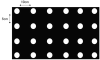
- FIG. 4 shows a plan view of the direct type backlight.
- the direct type backlight 30 has a substrate 32 and a plurality of point light sources 34 arranged two-dimensionally on the substrate 32.
- the plurality of point light sources 34 can be driven by a local dimming method, and the minimum unit of local dimming drive may be one point light source or two or more point light sources.
- the type of the point light source is not particularly limited, and examples thereof include an LED (light emitting diode) and a laser light source.
- the point light source may be a white light source, or a plurality of light sources having different emission colors may be used.
- a mini LED having a size S in FIG. 3 of 1.0 mm or less (preferably 0.6 mm or less, more preferably 0.15 mm or less) is preferable.
- the arrangement of the point light sources is preferably a grid arrangement arranged in a two-dimensional grid pattern, but may be a triangular arrangement, a hexagonal arrangement, or the like.
- the "lattice arrangement arranged in a two-dimensional lattice” is a multi-row arrangement in which light source sequences in which a plurality of point light sources are arranged at a constant pitch in one direction intersect in one direction. It means the arrangement in which the point light source is located at the grid point of the two-dimensional lattice.
- the lattice becomes a square, and the pitch of the point light source in the light source row and the light source row If the placement pitch is different, the grid will be rectangular.
- the lattice becomes a parallelogram.
- the point light sources are preferably arranged regularly, but may be arranged irregularly.
- the distance P between the closest point light sources is preferably 2 to 20 mm. In the case of regular arrangement, the distance between the point light sources means the arrangement pitch.
- the type of substrate on which the point light source is arranged is not particularly limited, but a reflector is preferable.
- the reflector include a white PET (polyethylene terephthalate) and a reflector having a reflective surface made of a multilayer film using a polyester resin.
- optical control member included in the liquid crystal display device of the present invention is not particularly limited as long as the above-mentioned requirements of the formulas (1) to (3) are satisfied, but the following aspects 1 to 3 are preferable.
- Aspect 1 First optically anisotropic layer satisfying the relationship of the formulas (4) to (6) described later
- Aspect 2 A light absorption anisotropic layer containing a dichroic substance, which is a light absorption anisotropic layer.
- a louver layer in which light-transmitting bands and light-shielding bands are alternately and repeatedly arranged.
- Examples of the optical control member include a first optically anisotropic layer satisfying the relationships of the formulas (4) to (6).
- Equation (4) 0 nm ⁇ Re1 (550) ⁇ 300 nm Equation (5) 100 nm ⁇
- ⁇ 1.2 Re1 (550) represents the in-plane retardation of the first optically anisotropic layer at a wavelength of 550 nm.
- Rth1 (550) represents the retardation in the thickness direction of the first optically anisotropic layer at a wavelength of 550 nm.
- Nz represents the Nz factor of the first optically anisotropic layer.
- the composition of the first optically anisotropic layer is not particularly limited as long as it satisfies the above optical characteristics, and is formed by using, for example, a polymer film (particularly, a stretched polymer film) and a liquid crystal compound.
- a polymer film particularly, a stretched polymer film
- a liquid crystal compound particularly, a polymer film and a liquid crystal compound.
- the light control member is a light absorption anisotropic layer containing a dichroic substance, and the light absorption differs when the direction having the highest transmittance with respect to the surface of the light absorption anisotropic layer is set as the transmission axis.
- Examples thereof include a light absorption anisotropic layer in which the angle formed by the normal direction of the rectangular layer and the transmission axis is 0 to 45 °.
- the angle formed by the normal direction of the light absorption anisotropic layer and the transmission axis is more preferably 0 to 20 ° and further preferably 0 to 10 ° in that the effect of the present invention is more excellent.
- the Mueller matrix of the light absorption anisotropic layer at a wavelength of 550 nm is measured in AxoScan OPMF-1 (manufactured by Optoscience).
- the transmittance at all omnidirectional angles at each polar angle was measured while changing the polar angle, which is the angle of the light absorption anisotropic layer with respect to the normal direction, from 0 to 90 ° in 5 ° increments.
- the direction in which the transmittance becomes the largest is defined as the transmission axis.
- the angle formed by the major axis of the dichroic substance and the thickness direction of the light absorption anisotropic layer is 0 to 45 ° ( It is preferable to adjust the temperature so that it is 0 to 20 °). Above all, it is preferable to vertically orient the dichroic substance in the light absorption anisotropic layer. In other words, it is preferable to orient the dichroic substance so that the long axis direction of the dichroic substance is substantially parallel to the thickness direction of the anisotropic light absorption layer. "Approximately parallel" means that the angle between the long axis direction of the dichroic substance and the thickness direction of the anisotropic light absorption layer is 0 to 45 °.
- the degree of orientation of the light absorption anisotropic layer at a wavelength of 550 nm is not particularly limited, but 0.80 or more is preferable, 0.90 or more is more preferable, and 0.95 or more is further preferable, in that the effect of the present invention is more excellent. ..
- the upper limit is 1.00.
- the degree of orientation is calculated by the following method. First, in AxoScan OPMF-1 (manufactured by Optoscience), the Mueller matrix of the light absorption anisotropic layer at a wavelength of 550 nm is measured at a polar angle of ⁇ 70 ° to 70 ° every 5 °.
- ko [ ⁇ ] and ke [ ⁇ ] are calculated by fitting to the following theoretical formulas in consideration of Snell's formula and Fresnel's formula.
- k -log (T) ⁇ ⁇ / (4 ⁇ d)
- the absorbance and the two-color ratio in the in-plane direction and the thickness direction are calculated, and finally the degree of orientation is obtained.
- the transmittance of the light absorption anisotropic layer at a wavelength of 550 nm in the front direction is preferably 70% or more, more preferably 80% or more.
- the upper limit is not particularly limited, but it is often 90% or less.
- the transmittance at a wavelength of 550 nm in a direction inclined by 30 ° from the transmission axis is preferably 60% or less, more preferably 40% or less, still more preferably 30% or less.
- the transmittance of the above-mentioned light absorption anisotropic layer can be appropriately adjusted depending on the concentration of the dichroic substance, the thickness of the light absorption anisotropic layer, and the like.
- the light absorption anisotropic layer is preferably formed by using a composition containing a dichroic substance and a liquid crystal compound.
- the dichroic substance is a substance having different properties between the absorbance in the major axis direction and the absorbance in the minor axis direction. Examples of the dichroic substance include a rod-shaped dichroic substance and a disk-shaped dichroic substance depending on its molecular shape, and a rod-shaped dichroic substance is preferable.
- the maximum absorption wavelength of the dichroic substance is preferably 400 to 500 nm, more preferably 440 to 480 nm.
- the dichroic substance examples include an acridine dye, an oxazine dye, a cyanine dye, a naphthalene dye, an azo dye, and an anthraquinone dye, and the azo dye is preferable.
- the azo dye examples include a monoazo dye, a bisazo dye, a trisazo dye, a tetrakisazo dye, and a stilbene azo dye, and a bisazo dye or a trisazo dye is preferable. Further, the compound described in JP-A-2018-053167 is also preferable.
- the dichroic substance may have a polymerizable group. Since the dichroic substance has a polymerizable group, the degree of cross-linking of the anisotropic light absorbing layer does not decrease even when the amount of the dichroic substance used is large, and even if it is thin, it exhibits high selective wavelength absorption and is durable. An anisotropic light absorption layer having excellent properties can be formed.
- an ethylenically unsaturated bond such as a vinyl group, a vinyloxy group, a styryl group, a p- (2-phenylethenyl) phenyl group, an acryloyl group, a methacryloyl group, an acryloyloxy group, and a methacryloyloxy group can be used.
- examples thereof include a polymerizable group, an epoxy group, and an oxetanyl group having.
- the dichroic material preferably has an aromatic ring.
- the aromatic ring include an aromatic hydrocarbon ring and an aromatic heterocycle, and among them, an aromatic hydrocarbon ring is preferable, and a benzene ring is more preferable.
- the liquid crystal compound preferably has a polymerizable group. That is, the composition preferably contains a polymerizable liquid crystal compound (a liquid crystal compound having a polymerizable group).
- the definition of the polymerizable group is as described in the section on dichroic substances.
- the liquid crystal compound preferably has an aromatic ring. Examples of the aromatic ring include an aromatic hydrocarbon ring and an aromatic heterocycle, and among them, an aromatic hydrocarbon ring is preferable, and a benzene ring is more preferable.
- the polymerizable liquid crystal compound examples include a low molecular weight liquid crystal compound having a polymerizable group and a high molecular weight liquid crystal compound having a polymerizable group.
- the "low molecular weight liquid crystal compound” means a liquid crystal compound having no repeating unit in the chemical structure.
- the "polymer liquid crystal compound” means a liquid crystal compound having a repeating unit in the chemical structure.
- the small molecule liquid crystal compound include the compounds described in JP2013-228706A.
- the polymer liquid crystal compound examples include a thermotropic liquid crystal polymer described in JP-A-2011-237513 and a side chain type liquid crystal compound described in JP-A-2015-107492. ..
- Low-molecular-weight liquid crystal compounds can be roughly classified into rod-shaped liquid crystal compounds and disc-shaped liquid crystal compounds according to their molecular shape.
- a rod-shaped liquid crystal compound is preferable.
- the polymer liquid crystal compound can be roughly classified into a main chain type liquid crystal compound and a side chain type liquid crystal compound, and the main chain type liquid crystal compound is a compound having a structure showing liquidity in the polymer main chain.
- the side-chain type liquid crystal compound is a compound having a structure showing liquidity in the polymer side chain portion.
- Side-chain liquid crystal compounds are preferable because the obtained anisotropic light absorbing layer has a high degree of orientation order and is excellent in solubility in a solvent when preparing a composition.
- the composition may contain other components other than the dichroic substance and the liquid crystal compound.
- the composition preferably contains a vertical alignment agent.
- the orientation of the dichroic substance and the liquid crystal compound can be made more vertical, and the degree of orientation order can be made higher.
- the vertical alignment agent include a boronic acid compound and an onium salt.
- Other components include leveling agents, polymerization initiators, and solvents.
- the method for forming the anisotropic light absorbing layer using the above-mentioned composition is not particularly limited, and is also referred to as a step of applying the above composition on a predetermined substrate to form a coating film (hereinafter, also referred to as a “coating film forming step”). ), The step of aligning the liquid crystal component contained in the coating film (hereinafter, also referred to as “alignment step”), and the step of applying a curing treatment to the coating film (hereinafter, also referred to as “curing step”). The method of including in order is mentioned. Hereinafter, each of the above steps will be described in detail.
- the coating film forming step is a step of applying a composition on a predetermined substrate to form a coating film.
- the type of the base material is not particularly limited, and examples thereof include a transparent support and a laminated body having an alignment film arranged on the transparent support.
- the method for applying the composition is not particularly limited, and examples thereof include known methods.
- the alignment step is a step of aligning the liquid crystal component contained in the coating film.
- the alignment step may have a drying process. By the drying treatment, components such as a solvent can be removed from the coating film.
- the orientation step preferably has a heat treatment. This makes it possible to orient the liquid crystal component contained in the coating film.
- the alignment step may have a cooling treatment performed after the heat treatment.
- the curing step is carried out, for example, by heating and / or light irradiation (exposure). Among these, it is preferable that the curing step is carried out by light irradiation.
- the light control member examples include a louver layer in which light transmission bands and light shielding bands are alternately and repeatedly arranged.
- the louver layer 40 the light transmission band 42 and the light shielding band 44 are alternately arranged.
- the first transparent protective layer 46 is laminated on one surface of the louver layer 40, and the second transparent protective layer 48 is laminated on the other surface.
- FIG. 6 is a cross-sectional view taken along the line II-II in FIG.
- the liquid crystal display device may or may not include a louver layer, and the first transparent protective layer 46 and the second transparent protective layer 48 may or may not be included.
- the light transmission band 42 and the light shielding band 44 constituting the louver layer 40 are used.
- Each has a band shape extending in the X direction, and a plurality of light transmission bands 42 and a plurality of light shielding bands 44 are alternately arranged in the Y direction.
- the width of the plurality of light transmission bands 42 in the Y direction is uniform and constant in the X direction. Further, the widths of the plurality of light-shielding bands 44 in the Y direction are also uniform and constant in the X direction.
- the material of the light transmission band 42 a resin having high transparency and low birefringence of transmitted light is used. From the viewpoint of transparency, high transparency is achieved such that the light transmittance when light is transmitted in the Z direction in the figure is 75% or more, preferably 85% or more, with respect to only the light transmission band 42.
- the resin material to have is preferable.
- specific examples of the resin having high transparency and small compound refraction include silicone resin, polycarbonate resin, polyolefin resin (particularly cycloolefin polymer), cellulose resin, and acrylic resin. Of these, silicone resin is preferable, and silicone rubber is more preferable because it has good heat resistance.
- the value of the above "light transmittance" is applied to the optical path of the inspection light in a device that uses D65 specified in JIS Z 8720 as a light source and measures the intensity of the inspection light emitted from the light source with a light receiving sensor.
- the output value of the light receiving sensor when there is no object to be measured is A
- the output value when the object to be measured is set on the optical path of the inspection light and the transmitted light transmitted through the object to be measured is received by the light source sensor is B.
- the value obtained by light transmittance (B / A) ⁇ 100 (unit;%).
- the material of the light-shielding band 44 a colored resin obtained by using the resin listed above as the material of the light-transmitting band 42 as a base material and adding a colorant such as a pigment and a dye to the base material is preferably used.
- the color tone of the light-shielding band 44 may be such that preferable light-shielding properties of the light-shielding band 44 can be obtained, and examples thereof include black, red, yellow, green, blue, and light blue.
- the color tone of the light-shielding band 44 can be adjusted by the type and amount of the colorant added.
- the colorant include general organic pigments or inorganic pigments such as carbon black, Benkara, iron oxide, titanium oxide, yellow iron oxide, disazo yellow, and phthalocyanine blue.
- the colorant may be used alone or in combination of two or more.
- a black pigment is not used, it is preferable to use a white pigment in combination in order to obtain good light-shielding properties.
- the resin material forming the light transmission band 42 and the resin material as the base material of the light shielding band 44 may be the same or different, but the light transmission band 42 and the light shielding band From the viewpoint of adhesiveness with 44, it is preferable that both are the same.
- the viewing angle ⁇ in the plane perpendicular to the X direction is determined by the thickness of the light transmission band 42 in the Z direction and the width in the Y direction. Further, the ratio of the width of the light transmitting band 42 to the width of the shading band 44 in the Y direction affects the transmittance of light rays parallel to the Z direction.
- the viewing angle ⁇ in the louver layer 40 is preferably 30 to 150 °, more preferably 60 to 120 °.
- the thickness T of the light transmission band 42 in the Z direction is preferably 50 to 200 ⁇ m, more preferably 100 to 200 ⁇ m.
- the width W1 of the light transmission band 42 in the Y direction is preferably 30 to 300 ⁇ m, more preferably 50 to 200 ⁇ m.
- the width W2 of the light-shielding band 44 in the Y direction is preferably 5 to 30 ⁇ m, more preferably 10 to 20 ⁇ m.
- the preferable range of the thickness T of the light-shielding band 44 in the Z direction is the same as the preferable range of the thickness T of the light transmission band 42.
- the material of the first transparent protective layer 46 and the second transparent protective layer 48 a resin having high transparency is used, and a resin having a small variation in birefringence in the plane is preferable. From the viewpoint of transparency, the light transmittance of each of the first transparent protective layer 46 and the second transparent protective layer 48 when light is transmitted in the Z direction in the figure is 75% or more. Is preferable, and 85% or more is more preferable.
- Specific examples of the resin having high transparency and small variation in the double refractive index in the plane in the state of being molded into a film include a polycarbonate resin, a polyolefin resin (particularly, a cycloolefin polymer), a cellulose resin, or a resin.
- the thickness of the first transparent protective layer 46 and the second transparent protective layer 48 is preferably 0.01 to 0.2 mm, more preferably 0.01 to 0.1 mm.
- the first transparent protective layer 46 and the second transparent protective layer 48 may be made of the same material, or may be made of different materials from each other. Further, the thickness of both may be the same or different. It is preferable that the first transparent protective layer 46 and the second transparent protective layer 48 are adhesively integrated with the louver layer 40 via an adhesive layer (not shown).
- the manufacturing method of the louver layer is not particularly limited, and examples thereof include the manufacturing method described in JP-A-2007-08142.
- the present invention is not limited to this mode, and the light transmission band and the light shielding band are inclined with respect to the thickness direction. There may be.
- the embodiment in which the light transmission band and the light shielding band have a certain width in the thick direction is described, but the present invention is not limited to this embodiment, and the width becomes narrower or wider as it goes in one direction. May be good.
- the structures of the light transmission band and the light shielding band can be adjusted as appropriate.
- the liquid crystal display device may have a member other than the above-mentioned member.
- the effects of the present invention are more excellent, and the formulas (7) to (8) are placed in at least one of the space between the first polarizing element and the liquid crystal cell and between the second polarizing element and the liquid crystal cell. It is preferable to have a second optically anisotropic layer including a positive A plate satisfying the relationship of) and a positive C plate satisfying the relationship of the formulas (9) to (10).
- ReA (550) represents the retardation of the positive A plate at a wavelength of 550 nm.
- ReA (450) represents the retardation of the positive A plate at a wavelength of 450 nm.
- RthC (550) represents the thickness direction retardation of the positive C plate at a wavelength of 550 nm.
- RthC (450) represents the thickness direction retardation of the positive C plate at a wavelength of 450 nm.
- the positive A plate preferably satisfies the relationship of the formulas (7A) to (8A) in that the effect of the present invention is more excellent.
- the positive C plate preferably satisfies the relationship of the formulas (9A) to (10A) in that the effect of the present invention is more excellent.
- the composition of the second optically anisotropic layer is not particularly limited as long as it satisfies the above optical characteristics, and is formed by using, for example, a polymer film (particularly, a stretched polymer film) and a liquid crystal compound.
- a polymer film particularly, a stretched polymer film
- a liquid crystal compound particularly, a polymer film (particularly, a stretched polymer film) and a liquid crystal compound. The film is mentioned.
- the liquid crystal display device has a third optical anisotropy that satisfies the relationship of the equations (11) to (12) in at least one of the space between the first polarizing element and the liquid crystal cell and the space between the second polarizing element and the liquid crystal cell. It is preferable to have a sex layer.
- Equation (11) 200 nm ⁇ Re3 (550) ⁇ 400 nm Equation (12) 0 nm ⁇
- Rth3 (550) represents the retardation in the thickness direction of the third optically anisotropic layer at a wavelength of 550 nm.
- represents the absolute value of Rth3 (550).
- the third optically anisotropic layer preferably satisfies the formulas (11A) to (12A) in that the effect of the present invention is more excellent. Equation (11A) 250 nm ⁇ Re3 (550) ⁇ 350 nm Equation (12A) 0 nm ⁇
- the composition of the third optically anisotropic layer is not particularly limited as long as it satisfies the above optical characteristics, and is formed by using, for example, a polymer film (particularly, a stretched polymer film) and a liquid crystal compound.
- a polymer film particularly, a stretched polymer film
- a liquid crystal compound particularly, a polymer film (particularly, a stretched polymer film) and a liquid crystal compound. The film is mentioned.
- the liquid crystal display device may have a light diffusing plate.
- the light diffusing plate is preferably arranged between the light control member and the direct type backlight.
- the light diffusing plate is a plate for disturbing the traveling direction of the incident light so that light having uniform brightness can be emitted from the main surface (plate surface).
- a known light diffusing plate can be used as the light diffusing plate.
- the liquid crystal display device may have a luminance improving film.
- the luminance improving film is preferably arranged between the optical control member and the direct type backlight. It is preferable that the brightness improving film is arranged on the visual recognition side (the side opposite to the direct type backlight) with respect to the light diffusing plate.
- Examples of the luminance improving film include a reflective polarizing film.
- the reflective polarizing film has a function of separating linear polarization, for example, it is arranged between the second polarizing element and the direct backlight, and the linear polarization is backscattered or backscattered to the direct backlight side.
- Examples of the multi-layered luminance improving film using the principle of the dielectric mirror include DBEF-E, DBEF-D, DBEF-M, and DBEF-P2 (all manufactured by 3M).
- Example 1 By biaxially stretching Arton (manufactured by JSR), an optically anisotropic film 1 having Re (550) of 100 nm, Rth (550) of -300 nm, and an Nz factor of -2.5 was produced. did. After that, the second polarization arranged on the back light side of ProArt PA32UCX manufactured by ASUS, which has a first polarizing element, a liquid crystal cell, a second polarizing element, a brightness improving film, a light diffusing plate, and a direct type backlight in this order.
- the above-mentioned optically anisotropic film 1 is attached to the child via an adhesive, and the above is applied between the second polarizing element and the direct type backlight (also applicable between the second polarizing element and the brightness improving film).
- the liquid crystal display device of Example 1 was produced by arranging the optically anisotropic film 1.
- the direct type backlight was equipped with a plurality of mini LEDs as point light sources.
- Example 2 (Formation of alignment film)
- TAC substrate having a thickness of 40 ⁇ m; TG40 FUJIFILM Corporation
- a composition for forming an alignment film was applied thereto with a wire bar.
- the support on which the coating film was formed was dried with warm air at 60 ° C. for 60 seconds and further dried with warm air at 100 ° C. for 120 seconds to form an alignment film, and a TAC film with an alignment film was obtained.
- the film thickness of the alignment film was 1 ⁇ m.
- composition for forming an alignment film ⁇ ⁇ Modified polyvinyl alcohol PVA-1 3.80 parts by mass ⁇ IRGACURE2959 0.20 parts by mass ⁇ 70 parts by mass of water ⁇ 30 parts by mass of methanol ⁇ ⁇
- the following composition for forming a light absorption anisotropic layer is continuously applied onto the obtained alignment film with a wire bar, and the obtained coating film is heated at 120 ° C. for 60 seconds and then at room temperature (23 ° C.). It was cooled until it became. Then, the support on which the coating film was formed was heated at 80 ° C. for 60 seconds and cooled again to room temperature. Then, the obtained coating film was irradiated with an LED lamp (center wavelength 365 nm) for 2 seconds under an irradiation condition of an illuminance of 200 mW / cm 2 , to prepare a light absorption anisotropic layer on the alignment film. ..
- the film thickness of the light absorption anisotropic layer was 3.0 ⁇ m.
- the transmittance of the light absorption anisotropic layer at a wavelength of 550 nm was 80%, and the degree of orientation was 0.97. Further, the angle formed by the transmission axis of the above-mentioned optically anisotropic layer and the normal direction of the light absorption anisotropic layer was 0 °.
- the following composition for forming a color adjusting layer was continuously applied on the obtained light absorption anisotropic layer with a wire bar to form a coating film.
- the support on which the coating film was formed was dried with warm air at 60 ° C. for 60 seconds and further dried with warm air at 100 ° C. for 120 seconds to form a color adjustment layer to form an optical film.
- the film thickness of the color adjustment layer was 0.5 ⁇ m.
- composition for forming a color adjusting layer ⁇ ⁇ Modified polyvinyl alcohol PVA-1 3.80 parts by mass ⁇ IRGACURE2959 0.20 parts by mass ⁇ Dye compound G-1 0.08 parts by mass ⁇ 70 parts by mass of water ⁇ 30 parts by mass of methanol ⁇ ⁇
- the above optical film is attached to a second polarizing element arranged on the backlight side of ProArt PA32UCX manufactured by ASUS, which has a first polarizing element, a liquid crystal cell, a second polarizing element, and a direct type backlight in this order.
- the optical film is formed.
- a liquid crystal display device was manufactured.
- Example 3 The optical difference produced in Example 1 was applied to the second polarizing element arranged on the backlight side of ProArt PA32UCX manufactured by ASUS, which has a first polarizing element, a liquid crystal cell, a second polarizing element, and a direct type backlight in this order.
- the optical film containing the light absorption anisotropic layer prepared in the square film 1 and the second embodiment is bonded to each other via an adhesive, and is placed between the second polarizing element and the direct type backlight (with the second polarizing element).
- the liquid crystal display device of Example 3 was produced by arranging the optically anisotropic film 1 and the optical film in the space between the brightness improving film and the liquid crystal display device.
- the width W2 of the light-shielding band shown in FIG. 6 is 15 ⁇ m
- the width of the light-transmitting band W1 is 70 ⁇ m
- the thickness T of the light-shielding band and the light-transmitting band is 150 ⁇ m.
- a louver layer in which a light transmission band and a light shielding band are alternately and repeatedly arranged was produced.
- a liquid crystal display device was produced according to the same procedure as in Example 1 except that the louver layer was used instead of the optically anisotropic film.
- the louver layer was arranged so that the absorption axis of the second polarizing element and the direction in which the light transmission band of the louver layer extends were orthogonal to each other.
- Example 6 An optically anisotropic film 3 having Re (550) of 280 nm and
- Example 7 The optically anisotropic film 2 was arranged between the first polarizing element in the liquid crystal display device manufactured in Example 4 and the liquid crystal cell to manufacture a liquid crystal display device.
- the optically anisotropic film 2 was arranged so that the slow axis of the optically anisotropic film 2 and the absorption axis of the first polarizing element were parallel to each other.
- Example 8> The optically anisotropic film 3 was arranged between the second polarizing element and the liquid crystal cell in the liquid crystal display device produced in Example 4, to produce a liquid crystal display device.
- the optically anisotropic film 3 was arranged so that the slow axis of the optically anisotropic film 3 and the absorption axis of the second substituent were orthogonal to each other.
- the width of the light-shielding band W2 shown in FIG. 6 is 30 ⁇ m
- the width of the light-transmitting band W1 is 20 ⁇ m
- the thickness T of the light-shielding band and the light-transmitting band is 300 ⁇ m.
- a louver layer in which a light transmission band and a light shielding band are alternately and repeatedly arranged was produced.
- a liquid crystal display device was produced according to the same procedure as in Example 1 except that the louver layer was used instead of the optically anisotropic film.
- the louver layer was arranged so that the absorption axis of the second polarizing element and the direction in which the light transmission band of the louver layer extends were orthogonal to each other.
- the liquid crystal display device is displayed in white in a dark room, and a measuring device (EZ-Contrast XL88, manufactured by ELDIM) is used to display the liquid crystal display at a predetermined polar position and azimuth position. It was obtained by measuring the white brightness. More specifically, the liquid crystal display device is displayed in white in a dark room, the polar angle is 0 ° ( ⁇ in FIG. 2 is 0 °), and the azimuth angle is 0 ° ( ⁇ in FIG. 2 is 0 °).
- I0 was obtained by arranging a measuring device at the position of and measuring the brightness.
- I20 first, the liquid crystal display device is displayed in white in a dark room, and the polar angle is 20 ° ( ⁇ in FIG. 2 is 20 °) and the azimuth angle is 45 ° ( ⁇ in FIG. 2 is 45 °).
- a measuring machine is placed at the position to obtain the brightness (brightness 20A), and the measuring machine is located at a polar angle of 20 ° ( ⁇ in FIG. 2 is 20 °) and an azimuth of 135 ° ( ⁇ is 135 ° in FIG. 2).
- the measuring instrument is placed at a position where the polar angle is 20 ° ( ⁇ in FIG.
- luminance 20A, luminance 20B, luminance 20C, luminance 20D were arithmetically averaged, and the average luminance was obtained and used as I20.
- the liquid crystal display device is displayed in white in a dark room, and the polar angle is 40 ° ( ⁇ in FIG. 2 is 40 °) and the azimuth angle is 45 ° ( ⁇ in FIG. 2 is 45 °).
- a measuring machine is placed at the position to obtain the brightness (brightness 40A), and the measuring machine is located at a polar angle of 40 ° ( ⁇ in FIG. 2 is 40 °) and an azimuth angle of 135 ° ( ⁇ is 135 ° in FIG. 2).
- the measuring instrument is placed at a position where the polar angle is 40 ° ( ⁇ in FIG.
- luminance 40A, luminance 40B, luminance 40C, luminance 40D were arithmetically averaged to obtain the average luminance, which was designated as I40.
- the liquid crystal display device is displayed in white in a dark room, and the polar angle is 60 ° ( ⁇ in FIG. 2 is 60 °) and the azimuth angle is 45 ° ( ⁇ in FIG. 2 is 45 °).
- a measuring machine is placed at the position to obtain the brightness (brightness 60A), and the measuring machine is located at a polar angle of 60 ° ( ⁇ in FIG. 2 is 60 °) and an azimuth of 135 ° ( ⁇ is 135 ° in FIG. 2).
- Is placed to obtain the brightness (brightness 60B) and the measuring instrument is placed at a position where the polar angle is 60 ° ( ⁇ in FIG.
- luminance 60A, luminance 60B, luminance 60C, luminance 60D were arithmetically averaged to obtain the average luminance, which was designated as I60.
- the liquid crystal display device of the present invention shows a desired effect. From the comparison between Examples 3 and 5 and 6, it was confirmed that a better effect can be obtained when the second optically anisotropic layer or the third optically anisotropic layer is used. From the comparison of Examples 1, 2 and 3, it was confirmed that a better effect can be obtained when the louver layer is used. From the comparison of Examples 1 to 3, it was confirmed that more excellent effects can be obtained when both the first optically anisotropic layer and the light absorption anisotropic layer are used.
- Liquid crystal display 12 1st liquid crystal display 14 Liquid crystal cell 16 2nd polarizing element 18 Optical control member 20, 30 Direct type backlight 22 Upper board 24 Lower board 26 Liquid crystal layer 32 Board 34 Point light source 40 Louver layer 42 Light transmission band 44 Light-shielding band 46 First transparent protective layer 48 Second transparent protective layer
Abstract
The present invention provides a liquid crystal display device having excellent display quality and suppressed generation of halo. The liquid crystal display device of the present invention has a first polarizer, a liquid crystal cell, a second polarizer, and a direct-type backlight that uses a point light source, wherein the liquid crystal display device further has a light control member between the second polarizer and the direct-type backlight, and the relationships of expressions (1) to (3) are satisfied. 70%≤(I20/I0)×100≤90%...expression (1), 10%≤(I40/I0)×100≤35%...expression (2), and 1%≤(I60/I0)×100≤20%...expression (3)
Description
本発明は、液晶表示装置に関する。
The present invention relates to a liquid crystal display device.
液晶表示装置は、印加電圧の変化に伴って液晶の透過率が変化することを利用し、電気的な情報を視覚情報に変えて表示する電子素子である。
液晶表示装置においてはバックライトユニットが使用されており、例えば、特許文献1では、液晶表示パネルの真下に配置された直下型バックライトが使用されている。 The liquid crystal display device is an electronic element that converts electrical information into visual information and displays it by utilizing the fact that the transmittance of the liquid crystal changes with the change of the applied voltage.
A backlight unit is used in the liquid crystal display device. For example, in Patent Document 1, a direct type backlight arranged directly under the liquid crystal display panel is used.
本発明者らは、特許文献1に記載されるような直下型バックライトの液晶表示装置の特性について検討したところ、明暗差が大きい部分において、本来、黒を表示する部分にも光が回り込んで明部の輪郭が滲んでしまうハローが生じることを知見した。
また、液晶表示装置においては、表示品位に優れることも合わせて求められる。 When the present inventors examined the characteristics of the liquid crystal display device of the direct-type backlight as described in Patent Document 1, the light wraps around the portion that originally displays black in the portion where the difference in brightness is large. It was found that a halo that blurs the outline of the bright part occurs.
In addition, the liquid crystal display device is also required to have excellent display quality.
本発明は、上記実情に鑑みて、表示品位に優れ、ハローの発生が抑制された液晶表示装置を提供することを課題とする。
In view of the above circumstances, it is an object of the present invention to provide a liquid crystal display device having excellent display quality and suppressed generation of halo.
本発明者らは、従来技術の問題点について鋭意検討した結果、以下の構成により上記課題を解決できることを見出した。
As a result of diligent studies on the problems of the prior art, the present inventors have found that the above problems can be solved by the following configuration.
(1) 第1偏光子と、
液晶セルと、
第2偏光子と、
点光源を利用する直下型バックライトと、この順で有する、液晶表示装置であって、
第2偏光子と、直下型バックライトとの間に、さらに光制御部材を有し、
後述する式(1)~(3)の関係を満たす、液晶表示装置。
(2) 光制御部材が、後述する式(4)~(6)の関係を満たす第1光学異方性層を有する、(1)に記載の液晶表示装置。
(3) 光制御部材が、二色性物質を含む光吸収異方性層を有し、
光吸収異方性層の表面に対して最も透過率が高い方向を透過軸とした際に、光吸収異方性層の法線方向と透過軸とのなす角度が0~45°である、(1)または(2)に記載の液晶表示装置。
(4) 光制御部材が、光透過帯と遮光帯とが交互に繰り返して配置されているルーバー層を有する、(1)~(3)のいずれかに記載の液晶表示装置。
(5) 第1偏光子と液晶セルとの間、および、第2偏光子と液晶セルとの間の少なくとも一方に、後述する式(7)~(8)の関係を満たすポジティブAプレートと、後述する式(9)~(10)の関係を満たすポジティブCプレートとを含む第2光学異方性層を有する、(1)~(4)のいずれかに記載の液晶表示装置。
(6) 第1偏光子と液晶セルとの間、および、第2偏光子と液晶セルとの間の少なくとも一方に、後述する式(11)~(12)の関係を満たす第3光学異方性層を有する、(1)~(5)のいずれかに記載の液晶表示装置。 (1) With the first polarizing element
LCD cell and
With the second splitter,
A direct-type backlight that uses a point light source, and a liquid crystal display device that has this order.
An optical control member is further provided between the second polarizing element and the direct type backlight.
A liquid crystal display device that satisfies the relationship of the formulas (1) to (3) described later.
(2) The liquid crystal display device according to (1), wherein the optical control member has a first optically anisotropic layer satisfying the relationships of the formulas (4) to (6) described later.
(3) The light control member has a light absorption anisotropic layer containing a dichroic substance.
When the direction having the highest transmittance with respect to the surface of the light absorption anisotropic layer is set as the transmission axis, the angle formed by the normal direction of the light absorption anisotropic layer and the transmission axis is 0 to 45 °. The liquid crystal display device according to (1) or (2).
(4) The liquid crystal display device according to any one of (1) to (3), wherein the light control member has a louver layer in which light transmission bands and light shielding bands are alternately and repeatedly arranged.
(5) A positive A plate satisfying the relationship of the formulas (7) to (8) described later in at least one of the space between the first polarizing element and the liquid crystal cell and between the second classifier and the liquid crystal cell. The liquid crystal display device according to any one of (1) to (4), which has a second optically anisotropic layer including a positive C plate satisfying the relationship of the formulas (9) to (10) described later.
(6) A third optical anisotropy that satisfies the relationship of the formulas (11) to (12) described later in at least one of the space between the first polarizing element and the liquid crystal cell and between the second classifier and the liquid crystal cell. The liquid crystal display device according to any one of (1) to (5), which has a sex layer.
本発明によれば、表示品位に優れ、ハローの発生が抑制された液晶表示装置を提供できる。
According to the present invention, it is possible to provide a liquid crystal display device having excellent display quality and suppressing the generation of halo.
以下、本発明について詳細に説明する。なお、本明細書において「~」を用いて表される数値範囲は、「~」の前後に記載される数値を下限値および上限値として含む範囲を意味する。まず、本明細書で用いられる用語について説明する。
Hereinafter, the present invention will be described in detail. In addition, the numerical range represented by using "-" in this specification means the range including the numerical values before and after "-" as the lower limit value and the upper limit value. First, the terms used in the present specification will be described.
遅相軸は、特別な断りがなければ、波長550nmにおける定義である。
The slow phase axis is defined at a wavelength of 550 nm unless otherwise specified.
本発明において、Re(λ)およびRth(λ)は各々、波長λにおける面内のレタデーションおよび厚み方向のレタデーションを表す。特に記載がないときは、波長λは、550nmとする。
本発明において、Re(λ)およびRth(λ)はAxoScan(Axometrics社製)において、波長λで測定した値である。AxoScanにて平均屈折率((nx+ny+nz)/3)と膜厚(d(μm))を入力することにより、
遅相軸方向(°)
Re(λ)=R0(λ)
Rth(λ)=((nx+ny)/2-nz)×d
が算出される。
なお、R0(λ)は、AxoScanで算出される数値として表示されるものであるが、Re(λ)を意味している。 In the present invention, Re (λ) and Rth (λ) represent in-plane retardation at wavelength λ and retardation in the thickness direction, respectively. Unless otherwise specified, the wavelength λ is 550 nm.
In the present invention, Re (λ) and Rth (λ) are values measured at a wavelength λ in AxoScan (manufactured by Axometrics). By inputting the average refractive index ((nx + ny + nz) / 3) and film thickness (d (μm)) in AxoScan,
Slow phase axial direction (°)
Re (λ) = R0 (λ)
Rth (λ) = ((nx + ny) /2-nz) × d
Is calculated.
Although R0 (λ) is displayed as a numerical value calculated by AxoScan, it means Re (λ).
本明細書において、屈折率nx、ny、および、nzは、アッベ屈折計(NAR-4T、アタゴ(株)製)を使用し、光源にナトリウムランプ(λ=589nm)を用いて測定する。また、波長依存性を測定する場合は、多波長アッベ屈折計DR-M2(アタゴ(株)製)にて、干渉フィルターとの組み合わせで測定できる。
また、ポリマーハンドブック(JOHN WILEY&SONS,INC)、および、各種光学フィルムのカタログの値を使用できる。主な光学フィルムの平均屈折率の値を以下に例示する:セルロースアシレート(1.48)、シクロオレフィンポリマー(1.52)、ポリカーボネート(1.59)、ポリメチルメタクリレート(1.49)、および、ポリスチレン(1.59)。
また、本明細書において、Nzファクターとは、Nz=(nx-nz)/(nx-ny)で与えられる値である。 In the present specification, the refractive indexes nx, ny, and nz are measured by using an Abbe refractometer (NAR-4T, manufactured by Atago Co., Ltd.) and using a sodium lamp (λ = 589 nm) as a light source. Further, when measuring the wavelength dependence, it can be measured with a multi-wavelength Abbe refractometer DR-M2 (manufactured by Atago Co., Ltd.) in combination with an interference filter.
In addition, the values in the Polymer Handbook (JOHN WILEY & SONS, INC) and the catalogs of various optical films can be used. The values of the average refractive index of the main optical films are exemplified below: cellulose acylate (1.48), cycloolefin polymer (1.52), polycarbonate (1.59), polymethylmethacrylate (1.49), And polystyrene (1.59).
Further, in the present specification, the Nz factor is a value given by Nz = (nx-nz) / (nx-ny).
本明細書では、「可視光」とは、400~700nmの光のことをいう。
また、本明細書では、測定波長について特に付記がない場合は、測定波長は550nmである。 As used herein, the term "visible light" refers to light having a diameter of 400 to 700 nm.
Further, in the present specification, unless otherwise specified, the measurement wavelength is 550 nm.
また、本明細書では、測定波長について特に付記がない場合は、測定波長は550nmである。 As used herein, the term "visible light" refers to light having a diameter of 400 to 700 nm.
Further, in the present specification, unless otherwise specified, the measurement wavelength is 550 nm.
本明細書において、ポジティブAプレートは以下のように定義する。ポジティブAプレートは、フィルムの面内遅相軸方向(面内での屈折率が最大となる方向)の屈折率をnx、面内遅相軸と面内で直交する方向の屈折率をny、厚み方向の屈折率をnzとしたとき、以下の式(X)の関係を満たすものである。なお、ポジティブAプレートはRthが正の値を示す。
式(X):nx>ny≒nz
なお、上記「≒」とは、両者が完全に同一である場合だけでなく、両者が実質的に同一である場合も包含する。「実質的に同一」とは、例えば、(ny-nz)×d(ただし、dはフィルムの厚みである)が、-10~10nm、好ましくは-5~5nmの場合も「ny≒nz」に含まれる。
また、本明細書において、ポジティブCプレートは以下のように定義する。ポジティブCプレートは、フィルムの面内遅相軸方向(面内での屈折率が最大となる方向)の屈折率をnx、面内遅相軸と面内で直交する方向の屈折率をny、厚み方向の屈折率をnzとしたとき、以下の式(Y)の関係を満たすものである。なお、ポジティブCプレートはRthが負の値を示す。
式(Y):nx≒ny<nz
なお、上記「≒」とは、両者が完全に同一である場合だけでなく、両者が実質的に同一である場合も包含する。「実質的に同一」とは、例えば、(nx-ny)×d(ただし、dはフィルムの厚みである)が、-10~10nm、好ましくは-5~5nmの場合も「nx≒ny」に含まれる。 In the present specification, the positive A plate is defined as follows. In the positive A plate, the refractive index of the film in the in-plane slow phase axis direction (the direction in which the in-plane refractive index is maximized) is nx, and the refractive index in the direction orthogonal to the in-plane slow phase axis in the in-plane is ny. When the refractive index in the thickness direction is nz, the relationship of the following equation (X) is satisfied. The positive A plate shows a positive value for Rth.
Equation (X): nx> ny≈nz
In addition, the above-mentioned "≈" includes not only the case where both are completely the same but also the case where both are substantially the same. “Substantially the same” means, for example, “ny ≈ nz” when (ny-nz) × d (where d is the thickness of the film) is -10 to 10 nm, preferably -5 to 5 nm. include.
Further, in the present specification, the positive C plate is defined as follows. For the positive C plate, the refractive index of the film in the in-plane slow-phase axis direction (the direction in which the in-plane refractive index is maximized) is nx, and the refractive index in the direction orthogonal to the in-plane slow-phase axis is ny. When the refractive index in the thickness direction is nz, the relationship of the following equation (Y) is satisfied. The positive C plate shows a negative value for Rth.
Equation (Y): nx≈ny <nz
In addition, the above-mentioned "≈" includes not only the case where both are completely the same but also the case where both are substantially the same. "Substantially the same" means, for example, "nx≈ny" when (nx-ny) x d (where d is the thickness of the film) is -10 to 10 nm, preferably -5 to 5 nm. include.
本発明の液晶表示装置の特徴点としては、光制御部材を所定の位置に配置し、後述するI20/I0、I40/I0、および、I60/I0で表される輝度の比を調整している点が挙げられる。つまり、本発明においては、液晶表示装置の透過光のプロファイルを制御することにより、所望の効果が得られている。
As a feature of the liquid crystal display device of the present invention, an optical control member is arranged at a predetermined position, and the ratio of luminance represented by I20 / I0, I40 / I0, and I60 / I0, which will be described later, is adjusted. There are points. That is, in the present invention, a desired effect is obtained by controlling the profile of the transmitted light of the liquid crystal display device.
以下、本発明の液晶表示装置の一例を、図面を参照して説明する。
図1に示す液晶表示装置10は、第1偏光子12、液晶セル14(液晶セルの上側基板22、液晶層26、液晶セルの下側基板24)、第2偏光子16、光制御部材18、および、点光源を利用する直下型バックライト20をこの順に有する。液晶セル14は、上側基板22と下側基板24と、これらに挟持される液晶層26とを含む。
以下では、まず、液晶表示装置の特徴点である式(1)~(3)の関係について説明し、その後、液晶表示装置10を構成する部材について詳述する。 Hereinafter, an example of the liquid crystal display device of the present invention will be described with reference to the drawings.
The liquidcrystal display device 10 shown in FIG. 1 includes a first polarizing element 12, a liquid crystal cell 14 (upper substrate 22 of the liquid crystal cell, a liquid crystal layer 26, a lower substrate 24 of the liquid crystal cell), a second polarizing element 16, and an optical control member 18. , And a direct-type backlight 20 using a point light source in this order. The liquid crystal cell 14 includes an upper substrate 22, a lower substrate 24, and a liquid crystal layer 26 sandwiched between them.
Hereinafter, the relationship between the equations (1) to (3), which is a feature of the liquid crystal display device, will be described first, and then the members constituting the liquidcrystal display device 10 will be described in detail.
図1に示す液晶表示装置10は、第1偏光子12、液晶セル14(液晶セルの上側基板22、液晶層26、液晶セルの下側基板24)、第2偏光子16、光制御部材18、および、点光源を利用する直下型バックライト20をこの順に有する。液晶セル14は、上側基板22と下側基板24と、これらに挟持される液晶層26とを含む。
以下では、まず、液晶表示装置の特徴点である式(1)~(3)の関係について説明し、その後、液晶表示装置10を構成する部材について詳述する。 Hereinafter, an example of the liquid crystal display device of the present invention will be described with reference to the drawings.
The liquid
Hereinafter, the relationship between the equations (1) to (3), which is a feature of the liquid crystal display device, will be described first, and then the members constituting the liquid
本発明の液晶表示装置は、白表示での透過光が下記式(1)~(3)の関係を満たす。
式(1) 70%≦(I20/I0)×100≦90%
式(2) 10%≦(I40/I0)×100≦35%
式(3) 1%≦(I60/I0)×100≦20%
I0は、液晶表示装置を白表示にし、極角0°かつ方位角0°において測定される輝度を表し、
I20は、液晶表示装置を白表示にし、極角20°かつ方位角45°において測定される輝度と、極角20°かつ方位角135°において測定される輝度と、極角20°かつ方位角225°において測定される輝度と、極角20°かつ方位角315°において測定される輝度とを算術平均して得られる平均輝度を表し、
I40は、液晶表示装置を白表示にし、極角40°かつ方位角45°において測定される輝度と、極角40°かつ方位角135°において測定される輝度と、極角40°かつ方位角225°において測定される輝度と、極角40°かつ方位角315°において測定される輝度とを算術平均して得られる平均輝度を表し、
I60は、液晶表示装置を白表示にし、極角60°かつ方位角45°において測定される輝度と、極角60°かつ方位角135°において測定される輝度と、極角60°かつ方位角225°において測定される輝度と、極角60°かつ方位角315°において測定される輝度とを算術平均して得られる平均輝度を表す。
式(1)中の「(I20/I0)×100」はI0に対するI20の割合を表し、式(2)の「(I40/I0)×100」はI0に対するI40の割合を表し、式(3)の「(I60/I0)×100」はI0に対するI60の割合を表す。
I20、I40およびI60は、液晶表示装置を白表示し、所定の斜め方向から観察した際の輝度の平均値を表し、これらの平均輝度が正面方向の輝度であるI0に対して所定の範囲である場合に、所望の効果が得られる。 In the liquid crystal display device of the present invention, the transmitted light in the white display satisfies the relationship of the following formulas (1) to (3).
Equation (1) 70% ≤ (I20 / I0) x 100 ≤ 90%
Equation (2) 10% ≤ (I40 / I0) x 100 ≤ 35%
Equation (3) 1% ≤ (I60 / I0) x 100 ≤ 20%
I0 represents the brightness measured at a polar angle of 0 ° and an azimuth angle of 0 ° with the liquid crystal display device displayed in white.
The I20 displays the liquid crystal display device in white, and has brightness measured at a polar angle of 20 ° and an azimuth of 45 °, brightness measured at a polar angle of 20 ° and an azimuth of 135 °, and a polar angle of 20 ° and an azimuth. Represents the average brightness obtained by arithmetically averaging the brightness measured at 225 ° and the brightness measured at a polar angle of 20 ° and an azimuth of 315 °.
The I40 displays the liquid crystal display device in white, and has brightness measured at a polar angle of 40 ° and an azimuth of 45 °, brightness measured at a polar angle of 40 ° and an azimuth of 135 °, and a polar angle of 40 ° and an azimuth. Represents the average brightness obtained by arithmetically averaging the brightness measured at 225 ° and the brightness measured at a polar angle of 40 ° and an azimuth of 315 °.
The I60 displays the liquid crystal display device in white, and has brightness measured at a polar angle of 60 ° and an azimuth of 45 °, brightness measured at a polar angle of 60 ° and an azimuth of 135 °, and a polar angle of 60 ° and an azimuth. It represents the average brightness obtained by arithmetically averaging the brightness measured at 225 ° and the brightness measured at a polar angle of 60 ° and an azimuth of 315 °.
"(I20 / I0) x 100" in the formula (1) represents the ratio of I20 to I0, and "(I40 / I0) x 100" in the formula (2) represents the ratio of I40 to I0, and the formula (3). ) "(I60 / I0) x 100" represents the ratio of I60 to I0.
I20, I40 and I60 represent the average value of the luminance when the liquid crystal display device is displayed in white and observed from a predetermined oblique direction, and these average luminances are in a predetermined range with respect to I0 which is the luminance in the front direction. In some cases, the desired effect is obtained.
以下では、まず、図2に基づいて、上記極角および方位角について説明する。図2においては、図1中の液晶表示装置10の第1偏光子12のみを取り出した図に該当する。
図2においては、第1偏光子12の平面(主面。厚み方向に対して垂直な面)をxy平面とし、y軸方向を第1偏光子12の吸収軸とする。よって、図2においては、y軸方向が方位角0°の基準となる。図2に示すように、ベクトルv1とz軸の成す各θを極角(第1偏光子12の法線方向とのなす角)と定義し、ベクトルv1のxy平面への投射とy軸(第1偏光子12の吸収軸)とのなす角φを方位角と定義する。つまり、極角とは、第1偏光子の法線方向となす角を意味する。また、方位角とは第1偏光子の吸収軸とのなす角度を表す。
例えば、極角20°とは、図2中のθが20°である角度を意味する。また、方位角45°とは、図2中のφが45°である角度を意味する。
なお、本発明において、方位角を表す際には、液晶表示装置中の第1偏光子を視認側から見て、第1偏光子の吸収軸方向を基準に反時計回りを正の値で表す。よって、図2においては、方位角45°という場合、基準であるy軸から反時計回りに45°回転した方位を意味する。 In the following, first, the polar angle and the azimuth will be described with reference to FIG. FIG. 2 corresponds to a diagram in which only the firstpolarizing element 12 of the liquid crystal display device 10 in FIG. 1 is taken out.
In FIG. 2, the plane (main surface, which is perpendicular to the thickness direction) of thefirst splitter 12 is defined as the xy plane, and the y-axis direction is defined as the absorption axis of the first splitter 12. Therefore, in FIG. 2, the y-axis direction serves as a reference for the azimuth angle of 0 °. As shown in FIG. 2, each θ formed by the vector v1 and the z-axis is defined as a polar angle (angle formed by the normal direction of the first polarizing element 12), and the projection of the vector v1 on the xy plane and the y-axis ( The angle φ formed by the absorption axis of the first polarizing element 12) is defined as the azimuth angle. That is, the polar angle means an angle formed with the normal direction of the first polarizing element. The azimuth angle represents the angle formed by the absorption axis of the first polarizing element.
For example, the polar angle of 20 ° means an angle at which θ in FIG. 2 is 20 °. Further, the azimuth angle of 45 ° means an angle in which φ in FIG. 2 is 45 °.
In the present invention, when expressing the azimuth, the first polarizing element in the liquid crystal display device is viewed from the visual recognition side, and the counterclockwise direction is expressed as a positive value with respect to the absorption axis direction of the first polarizing element. .. Therefore, in FIG. 2, the azimuth angle of 45 ° means an azimuth rotated by 45 ° counterclockwise from the reference y-axis.
図2においては、第1偏光子12の平面(主面。厚み方向に対して垂直な面)をxy平面とし、y軸方向を第1偏光子12の吸収軸とする。よって、図2においては、y軸方向が方位角0°の基準となる。図2に示すように、ベクトルv1とz軸の成す各θを極角(第1偏光子12の法線方向とのなす角)と定義し、ベクトルv1のxy平面への投射とy軸(第1偏光子12の吸収軸)とのなす角φを方位角と定義する。つまり、極角とは、第1偏光子の法線方向となす角を意味する。また、方位角とは第1偏光子の吸収軸とのなす角度を表す。
例えば、極角20°とは、図2中のθが20°である角度を意味する。また、方位角45°とは、図2中のφが45°である角度を意味する。
なお、本発明において、方位角を表す際には、液晶表示装置中の第1偏光子を視認側から見て、第1偏光子の吸収軸方向を基準に反時計回りを正の値で表す。よって、図2においては、方位角45°という場合、基準であるy軸から反時計回りに45°回転した方位を意味する。 In the following, first, the polar angle and the azimuth will be described with reference to FIG. FIG. 2 corresponds to a diagram in which only the first
In FIG. 2, the plane (main surface, which is perpendicular to the thickness direction) of the
For example, the polar angle of 20 ° means an angle at which θ in FIG. 2 is 20 °. Further, the azimuth angle of 45 ° means an angle in which φ in FIG. 2 is 45 °.
In the present invention, when expressing the azimuth, the first polarizing element in the liquid crystal display device is viewed from the visual recognition side, and the counterclockwise direction is expressed as a positive value with respect to the absorption axis direction of the first polarizing element. .. Therefore, in FIG. 2, the azimuth angle of 45 ° means an azimuth rotated by 45 ° counterclockwise from the reference y-axis.
本発明の液晶表示装置は、ハローの効果がより抑制される点、および、表示品位がより優れる点の少なくとも一方の効果が得られる点(以下、単に「本発明の効果がより優れる点」ともいう。)で、式(1A)の関係を満たすことが好ましく、式(1B)の関係を満たすことがより好ましい。
式(1A) 73%≦(I20/I0)×100≦87%
式(1B) 76%≦(I20/I0)×100≦84%
また、本発明の液晶表示装置は、式(2A)の関係を満たすことが好ましく、式(2B)の関係を満たすことがより好ましい。
式(2A) 13%≦(I40/I0)×100≦30%
式(2B) 16%≦(I40/I0)×100≦19%
また、本発明の液晶表示装置は、式(3A)の関係を満たすことが好ましく、式(3B)の関係を満たすことがより好ましい。
式(3A) 1%≦(I60/I0)×100≦15%
式(3B) 2%≦(I60/I0)×100≦5% The liquid crystal display device of the present invention has a point that the effect of the halo is further suppressed and a point that at least one of a point where the display quality is more excellent can be obtained (hereinafter, also simply referred to as "a point where the effect of the present invention is more excellent"). It is preferable that the relationship of the formula (1A) is satisfied, and it is more preferable that the relationship of the formula (1B) is satisfied.
Equation (1A) 73% ≤ (I20 / I0) x 100 ≤ 87%
Equation (1B) 76% ≤ (I20 / I0) x 100 ≤ 84%
Further, the liquid crystal display device of the present invention preferably satisfies the relationship of the formula (2A), and more preferably satisfies the relationship of the formula (2B).
Equation (2A) 13% ≤ (I40 / I0) x 100 ≤ 30%
Equation (2B) 16% ≤ (I40 / I0) x 100 ≤ 19%
Further, the liquid crystal display device of the present invention preferably satisfies the relationship of the formula (3A), and more preferably satisfies the relationship of the formula (3B).
Equation (3A) 1% ≤ (I60 / I0) x 100 ≤ 15%
Equation (3B) 2% ≤ (I60 / I0) x 100 ≤ 5%
上記I0、I20、I40、および、I60は、暗室内で液晶表示装置を白表示させ、測定機(EZ-Contrast X L88、ELDIM社製)を用いて所定の極角位置および方位角位置での白輝度を計測することにより求める。
より具体的には、暗室内で液晶表示装置を白表示して、極角が0°(図2中のθが0°)で、方位角が0°(図2中のφが0°)の位置に測定機を配置して、輝度を測定することにより、I0を求める。
また、I20に関しては、まず、暗室内で液晶表示装置を白表示して、極角20°(図2中のθが20°)かつ方位角45°(図2中のφが45°)の位置に測定機を配置して輝度(輝度20A)を求め、極角20°(図2中のθが20°)かつ方位角135°(図2中のφが135°)の位置に測定機を配置して輝度(輝度20B)を求め、極角20°(図2中のθが20°)かつ方位角225°(図2中のφが225°)の位置に測定機を配置して輝度(輝度20C)を求め、極角20°(図2中のθが20°)かつ方位角315°(図2中のφが315°)の位置に測定機を配置して輝度(輝度20D)を求める。次に、得られた4つの輝度(輝度20A、輝度20B、輝度20C、輝度20D)を算術平均して、平均輝度を求めて、I20とする。
また、I40に関しては、まず、暗室内で液晶表示装置を白表示して、極角40°(図2中のθが40°)かつ方位角45°(図2中のφが45°)の位置に測定機を配置して輝度(輝度40A)を求め、極角40°(図2中のθが40°)かつ方位角135°(図2中のφが135°)の位置に測定機を配置して輝度(輝度40B)を求め、極角40°(図2中のθが40°)かつ方位角225°(図2中のφが225°)の位置に測定機を配置して輝度(輝度40C)を求め、極角40°(図2中のθが40°)かつ方位角315°(図2中のφが315°)の位置に測定機を配置して輝度(輝度40D)を求める。次に、得られた4つの輝度(輝度40A、輝度40B、輝度40C、輝度40D)を算術平均して、平均輝度を求めて、I40とする。
また、I60に関しては、まず、暗室内で液晶表示装置を白表示して、極角60°(図2中のθが60°)かつ方位角45°(図2中のφが45°)の位置に測定機を配置して輝度(輝度60A)を求め、極角60°(図2中のθが60°)かつ方位角135°(図2中のφが135°)の位置に測定機を配置して輝度(輝度60B)を求め、極角60°(図2中のθが60°)かつ方位角225°(図2中のφが225°)の位置に測定機を配置して輝度(輝度60C)を求め、極角60°(図2中のθが60°)かつ方位角315°(図2中のφが315°)の位置に測定機を配置して輝度(輝度60D)を求める。次に、得られた4つの輝度(輝度60A、輝度60B、輝度60C、輝度60D)を算術平均して、平均輝度を求めて、I60とする。 In the above I0, I20, I40, and I60, the liquid crystal display device is displayed in white in a dark room, and a measuring device (EZ-Contrast XL88, manufactured by ELDIM) is used to display the liquid crystal display at a predetermined polar position and azimuth position. Obtained by measuring the white brightness.
More specifically, the liquid crystal display device is displayed in white in a dark room, the polar angle is 0 ° (θ in FIG. 2 is 0 °), and the azimuth angle is 0 ° (φ in FIG. 2 is 0 °). I0 is obtained by arranging a measuring device at the position of and measuring the brightness.
Regarding I20, first, the liquid crystal display device is displayed in white in a dark room, and the polar angle is 20 ° (θ in FIG. 2 is 20 °) and the azimuth angle is 45 ° (φ in FIG. 2 is 45 °). A measuring machine is placed at the position to obtain the brightness (brightness 20A), and the measuring machine is located at a polar angle of 20 ° (θ in FIG. 2 is 20 °) and an azimuth of 135 ° (φ is 135 ° in FIG. 2). Is placed to obtain the brightness (brightness 20B), and the measuring instrument is placed at a position where the polar angle is 20 ° (θ in FIG. 2 is 20 °) and the azimuth angle is 225 ° (φ is 225 ° in FIG. 2). The brightness (brightness 20C) is obtained, and the measuring instrument is placed at a position where the polar angle is 20 ° (θ in FIG. 2 is 20 °) and the azimuth angle is 315 ° (φ is 315 ° in FIG. 2), and the brightness (brightness 20D) is obtained. ). Next, the four obtained luminances (luminance 20A, luminance 20B, luminance 20C, luminance 20D) are arithmetically averaged to obtain the average luminance, which is designated as I20.
Regarding I40, first, the liquid crystal display device is displayed in white in a dark room, and the polar angle is 40 ° (θ in FIG. 2 is 40 °) and the azimuth angle is 45 ° (φ in FIG. 2 is 45 °). A measuring machine is placed at the position to obtain the brightness (brightness 40A), and the measuring machine is located at a polar angle of 40 ° (θ in FIG. 2 is 40 °) and an azimuth angle of 135 ° (φ is 135 ° in FIG. 2). Is placed to obtain the brightness (brightness 40B), and the measuring instrument is placed at a position where the polar angle is 40 ° (θ in FIG. 2 is 40 °) and the azimuth angle is 225 ° (φ is 225 ° in FIG. 2). The brightness (brightness 40C) is obtained, and the measuring instrument is placed at a position where the polar angle is 40 ° (θ in FIG. 2 is 40 °) and the azimuth angle is 315 ° (φ is 315 ° in FIG. 2), and the brightness (brightness 40D) is obtained. ). Next, the four obtained luminances (luminance 40A, luminance 40B, luminance 40C, luminance 40D) are arithmetically averaged to obtain the average luminance, which is designated as I40.
Regarding I60, first, the liquid crystal display device is displayed in white in a dark room, and the polar angle is 60 ° (θ in FIG. 2 is 60 °) and the azimuth angle is 45 ° (φ in FIG. 2 is 45 °). A measuring machine is placed at the position to obtain the brightness (brightness 60A), and the measuring machine is located at a polar angle of 60 ° (θ in FIG. 2 is 60 °) and an azimuth of 135 ° (φ is 135 ° in FIG. 2). Is placed to obtain the brightness (brightness 60B), and the measuring instrument is placed at a position where the polar angle is 60 ° (θ in FIG. 2 is 60 °) and the azimuth angle is 225 ° (φ is 225 ° in FIG. 2). The brightness (brightness 60C) is obtained, and the measuring instrument is placed at a position where the polar angle is 60 ° (θ in FIG. 2 is 60 °) and the azimuth angle is 315 ° (φ is 315 ° in FIG. 2), and the brightness (brightness 60D) is obtained. ). Next, the four obtained luminances (luminance 60A, luminance 60B, luminance 60C, luminance 60D) are arithmetically averaged to obtain the average luminance, which is designated as I60.
<第1偏光子および第2偏光子>
第1偏光子および第2偏光子の種類は特に制限されず、公知の偏光子が挙げられる。
第1偏光子および第2偏光子としては、例えば、直線偏光子が好ましい。直線偏光子としては、バインダーとヨウ素若しくは二色性物質とからなる偏光子、または、塗布型偏光子が好ましい。
直線偏光子におけるヨウ素および二色性物質は、バインダー中で配向することで偏光性能を発現する。ヨウ素および二色性物質は、バインダー分子に沿って配向するか、または、二色性物質が液晶のような自己組織化により一方向に配向することが好ましい。現在、市販の偏光子は、延伸したポリマーを、浴槽中のヨウ素または二色性物質の溶液に浸漬し、ヨウ素または二色性物質をバインダー中に浸透させることで作製されることが一般的である。 <First and second polarizing elements>
The types of the first and second splitters are not particularly limited, and examples thereof include known modulators.
As the first and second splitters, for example, linear splitters are preferable. As the linear splitter, a splitter composed of a binder and iodine or a dichroic substance, or a coated type splitter is preferable.
Iodine and dichroic substances in linear modulators exhibit polarization performance by being oriented in the binder. Iodine and the dichroic material are preferably oriented along the binder molecule, or the dichroic material is preferably oriented in one direction by self-assembly such as liquid crystal display. Currently, commercially available splitters are generally made by immersing a stretched polymer in a solution of iodine or dichroic material in a bathtub and allowing the iodine or dichroic material to penetrate into the binder. be.
第1偏光子および第2偏光子の厚みは特に制限されないが、液晶表示装置の薄型化の点から、30μm以下が好ましく、15μm以下がより好ましく、10μm以下がさらに好ましい。特に、液晶表示装置の使用時および耐久試験時において、各部材間の寸法変化の違いにより、偏光子に亀裂および破断などの外観不良が発生することを抑止する点から、第1偏光子および第2偏光子の厚みは10μm以下が好ましく、7μm以下がより好ましく、3μm以下がさらに好ましい。
第1偏光子および第2偏光子の厚みの下限は特に制限されないが、機械的強度の点から、2μm以上が好ましい。 The thicknesses of the first and second splitters are not particularly limited, but are preferably 30 μm or less, more preferably 15 μm or less, still more preferably 10 μm or less, from the viewpoint of reducing the thickness of the liquid crystal display device. In particular, when the liquid crystal display device is used and when the durability test is performed, the first splitter and the first substituent are used from the viewpoint of suppressing the occurrence of appearance defects such as cracks and breaks in the polarizing element due to the difference in dimensional change between the members. The thickness of the bipolarizer is preferably 10 μm or less, more preferably 7 μm or less, still more preferably 3 μm or less.
The lower limit of the thickness of the first and second splitters is not particularly limited, but is preferably 2 μm or more from the viewpoint of mechanical strength.
<液晶セル>
液晶セルとしては、様々な表示モードの液晶セルを用いることができ、例えば、TN(Twisted Nematic)、IPS(In-Plane Switching)、FFS(Fringe Field Switching)、FLC(Ferroelectric Liquid Crystal)、AFLC(Anti-ferroelectric Liquid Crystal)、OCB(Optically Compensatory Bend)、STN(Supper Twisted Nematic)、VA(Vertically Aligned)、および、HAN(Hybrid Aligned Nematic)が挙げられる。 <LCD cell>
As the liquid crystal cell, a liquid crystal cell having various display modes can be used, for example, TN (Twisted Nematic), IPS (In-Plane Switching), FFS (Fringe Field Switching), FLC (Ferroelectric Liquid Crystal), AFLC. Anti-ferroelectric Liquid Crystal), OCB (Optical Liquid Crystal Bend), STN (Super Twisted Nematic), VA (Vertically Selected), and HAN (High).
液晶セルの構成は特に制限されないが、液晶層と、液晶層を挟むように配置される上側基板と下側基板とを有する態様が好ましい。上側基板および下側基板の種類は特に制限されないが、例えば、ガラス基板、および、樹脂基板が挙げられる。
上側基板および下側基板の少なくとも一方の基板の表面上には、電極(好ましくは、透明電極)が配置されることが好ましい。
液晶セルには、カラーフィルター層およびTFT(Thin Film Transistor)層が含まれていてもよい。カラーフィルター層およびTFT層の位置は特に制限されず、上側基板または下側基板のいずれかの表面に配置されることが一般的である。カラーフィルター層およびTFT層は、上側基板と下側基板との間に配置されることが好ましい。 The configuration of the liquid crystal cell is not particularly limited, but a mode having a liquid crystal layer and an upper substrate and a lower substrate arranged so as to sandwich the liquid crystal layer is preferable. The type of the upper substrate and the lower substrate is not particularly limited, and examples thereof include a glass substrate and a resin substrate.
It is preferable that an electrode (preferably a transparent electrode) is arranged on the surface of at least one of the upper substrate and the lower substrate.
The liquid crystal cell may include a color filter layer and a TFT (Thin Film Transistor) layer. The positions of the color filter layer and the TFT layer are not particularly limited, and are generally arranged on the surface of either the upper substrate or the lower substrate. The color filter layer and the TFT layer are preferably arranged between the upper substrate and the lower substrate.
液晶層中の液晶性化合物の遅相軸(黒表示時の遅相軸)と、第2偏光子の吸収軸とが平行になるよう配置されることが好ましい。
また、液晶セルは、少なくとも青色、緑色、および赤色のサブピクセルからなる画素を有することが好ましい。 It is preferable that the slow axis of the liquid crystal compound in the liquid crystal layer (the slow axis when displayed in black) and the absorption axis of the second polarizing element are arranged in parallel.
Also, the liquid crystal cell preferably has pixels consisting of at least blue, green, and red subpixels.
<直下型バックライト>
本発明の液晶表示装置は、点光源を利用する直下型バックライトを有する。直下型バックライトは、液晶セルの視認側とは反対側に点光源を有するバックライトである。
上記直下型バックライトの構成は特に制限されず、公知の直下型バックライトが挙げられる。
図3および4に、直下型バックライトの一例を示す。図3は、直下型バックライトの断面図を表し、図4は直下型バックライトの平面図を表す。
図3および4に示すように、直下型バックライト30は、基板32と、基板32上に2次元状に配置された複数の点光源34とを有する。複数の点光源34は、ローカルディミング方式による駆動が可能であり、ローカルディミング駆動の最小単位は1つの点光源であってもよいし、2つ以上の点光源であってもよい。 <Direct type backlight>
The liquid crystal display device of the present invention has a direct-type backlight that utilizes a point light source. The direct type backlight is a backlight having a point light source on the side opposite to the visual recognition side of the liquid crystal cell.
The configuration of the direct type backlight is not particularly limited, and examples thereof include known direct type backlights.
FIGS. 3 and 4 show an example of a direct type backlight. FIG. 3 shows a cross-sectional view of the direct type backlight, and FIG. 4 shows a plan view of the direct type backlight.
As shown in FIGS. 3 and 4, thedirect type backlight 30 has a substrate 32 and a plurality of point light sources 34 arranged two-dimensionally on the substrate 32. The plurality of point light sources 34 can be driven by a local dimming method, and the minimum unit of local dimming drive may be one point light source or two or more point light sources.
本発明の液晶表示装置は、点光源を利用する直下型バックライトを有する。直下型バックライトは、液晶セルの視認側とは反対側に点光源を有するバックライトである。
上記直下型バックライトの構成は特に制限されず、公知の直下型バックライトが挙げられる。
図3および4に、直下型バックライトの一例を示す。図3は、直下型バックライトの断面図を表し、図4は直下型バックライトの平面図を表す。
図3および4に示すように、直下型バックライト30は、基板32と、基板32上に2次元状に配置された複数の点光源34とを有する。複数の点光源34は、ローカルディミング方式による駆動が可能であり、ローカルディミング駆動の最小単位は1つの点光源であってもよいし、2つ以上の点光源であってもよい。 <Direct type backlight>
The liquid crystal display device of the present invention has a direct-type backlight that utilizes a point light source. The direct type backlight is a backlight having a point light source on the side opposite to the visual recognition side of the liquid crystal cell.
The configuration of the direct type backlight is not particularly limited, and examples thereof include known direct type backlights.
FIGS. 3 and 4 show an example of a direct type backlight. FIG. 3 shows a cross-sectional view of the direct type backlight, and FIG. 4 shows a plan view of the direct type backlight.
As shown in FIGS. 3 and 4, the
点光源の種類は特に制限されず、例えば、LED(light emitting diode)、および、レーザー光源が挙げられる。
点光源は白色光源であってもよいし、異なる発光色の光源が複数使用されてもよい。
点光源としては、図3中のサイズSが1.0mm以下(好ましくは0.6mm以下、より好ましくは0.15mm以下)のミニLEDが好ましい。
点光源の配置は、2次元格子状に配列された格子状配置が好適であるが、三角形配置および六角形配置などでもよい。なお、ここで「2次元格子状に配列された格子状配置」とは、一方向に一定のピッチで複数の点光源が配列された光源列が、その一方向に交差する方向に複数列配列され、2次元格子の格子点に点光源が位置した配置を意味する。上記一方向と交差する方向とが直交しており、光源列における点光源のピッチと光源列の配列ピッチとが同一である場合、格子が正方形となり、光源列における点光源のピッチと光源列の配置ピッチとが相違する場合、格子が長方形となる。また、上記一方向と交差する方向が直交していない場合、格子は平行四辺形となる。このように点光源は、規則的に配列されていることが好ましいが、不規則に配列されていてもよい。
なお、最も近い点光源同士の間隔Pは2~20mmであることが好ましい。規則配列されている場合には、点光源同士の間隔は配置ピッチを意味する。 The type of the point light source is not particularly limited, and examples thereof include an LED (light emitting diode) and a laser light source.
The point light source may be a white light source, or a plurality of light sources having different emission colors may be used.
As the point light source, a mini LED having a size S in FIG. 3 of 1.0 mm or less (preferably 0.6 mm or less, more preferably 0.15 mm or less) is preferable.
The arrangement of the point light sources is preferably a grid arrangement arranged in a two-dimensional grid pattern, but may be a triangular arrangement, a hexagonal arrangement, or the like. Here, the "lattice arrangement arranged in a two-dimensional lattice" is a multi-row arrangement in which light source sequences in which a plurality of point light sources are arranged at a constant pitch in one direction intersect in one direction. It means the arrangement in which the point light source is located at the grid point of the two-dimensional lattice. When the above one direction and the intersecting direction are orthogonal to each other and the pitch of the point light source in the light source row and the arrangement pitch of the light source row are the same, the lattice becomes a square, and the pitch of the point light source in the light source row and the light source row If the placement pitch is different, the grid will be rectangular. Further, when the directions intersecting with the above one direction are not orthogonal to each other, the lattice becomes a parallelogram. As described above, the point light sources are preferably arranged regularly, but may be arranged irregularly.
The distance P between the closest point light sources is preferably 2 to 20 mm. In the case of regular arrangement, the distance between the point light sources means the arrangement pitch.
点光源を配置する基板の種類は特に制限されないが、反射板が好ましい。
反射板としては、例えば、白色PET(polyethylene terephthalate)、および、ポリエステル系樹脂を用いた多層膜フィルムからなる反射面を有する反射板が挙げられる。 The type of substrate on which the point light source is arranged is not particularly limited, but a reflector is preferable.
Examples of the reflector include a white PET (polyethylene terephthalate) and a reflector having a reflective surface made of a multilayer film using a polyester resin.
<光制御部材>
本発明の液晶表示装置が有する光制御部材は上述した式(1)~(3)の要件が満たされれば特に制限されないが、以下の態様1~3が好ましい。
態様1:後述する式(4)~(6)の関係を満たす第1光学異方性層
態様2:二色性物質を含む光吸収異方性層であって、光吸収異方性層の表面に対して最も透過率が高い方向を透過軸とした際に、光吸収異方性層の法線方向と透過軸とのなす角度が0~45°である光吸収異方性層
態様3:光透過帯と遮光帯とが交互に繰り返して配置されているルーバー層
以下、態様1~3について詳述する。 <Optical control member>
The optical control member included in the liquid crystal display device of the present invention is not particularly limited as long as the above-mentioned requirements of the formulas (1) to (3) are satisfied, but the following aspects 1 to 3 are preferable.
Aspect 1: First optically anisotropic layer satisfying the relationship of the formulas (4) to (6) described later Aspect 2: A light absorption anisotropic layer containing a dichroic substance, which is a light absorption anisotropic layer. A mode 3 of the light absorption anisotropic layer in which the angle between the normal direction of the light absorption anisotropic layer and the transmission axis is 0 to 45 ° when the direction having the highest transmittance with respect to the surface is set as the transmission axis. : A louver layer in which light-transmitting bands and light-shielding bands are alternately and repeatedly arranged. Hereinafter, embodiments 1 to 3 will be described in detail.
(態様1)
光制御部材として、式(4)~(6)の関係を満たす第1光学異方性層が挙げられる。
式(4) 0nm≦Re1(550)≦300nm
式(5) 100nm≦|Rth1(550)|≦1000nm
式(6) |Nz|≧1.2
Re1(550)は、第1光学異方性層の波長550nmにおける面内レタデーションを表す。Rth1(550)は、第1光学異方性層の波長550nmにおける厚み方向のレタデーションを表す。Nzは、第1光学異方性層のNzファクターを表す。式(5)において|Rth1(550)|は、Rth1(550)の絶対値を表す。式(6)において|Nz|は、Nzファクターの絶対値を表す。
なかでも、本発明の効果がより優れる点で、第1光学異方性層は式(4A)~(6A)の関係を満たすことが好ましい。
式(4A) 100nm≦Re1(550)≦300nm
式(5A) 200nm≦|Rth1(550)|≦600nm
式(6A) 2.0≦|Nz|≦8.0 (Aspect 1)
Examples of the optical control member include a first optically anisotropic layer satisfying the relationships of the formulas (4) to (6).
Equation (4) 0 nm ≤ Re1 (550) ≤ 300 nm
Equation (5) 100 nm ≦ | Rth1 (550) | ≦ 1000 nm
Equation (6) | Nz | ≧ 1.2
Re1 (550) represents the in-plane retardation of the first optically anisotropic layer at a wavelength of 550 nm. Rth1 (550) represents the retardation in the thickness direction of the first optically anisotropic layer at a wavelength of 550 nm. Nz represents the Nz factor of the first optically anisotropic layer. In the formula (5), | Rth1 (550) | represents the absolute value of Rth1 (550). In the formula (6), | Nz | represents the absolute value of the Nz factor.
Above all, it is preferable that the first optically anisotropic layer satisfies the relationship of the formulas (4A) to (6A) in that the effect of the present invention is more excellent.
Formula (4A) 100 nm ≤ Re1 (550) ≤ 300 nm
Equation (5A) 200 nm ≦ | Rth1 (550) | ≦ 600 nm
Equation (6A) 2.0 ≦ | Nz | ≦ 8.0
第1光学異方性層は上記光学特性を満たせば、その構成は特に制限されず、例えば、ポリマーフィルム(特に、延伸処理が施されたポリマーフィルム)、および、液晶性化合物を用いて形成されたフィルムが挙げられる。
The composition of the first optically anisotropic layer is not particularly limited as long as it satisfies the above optical characteristics, and is formed by using, for example, a polymer film (particularly, a stretched polymer film) and a liquid crystal compound. The film is mentioned.
(態様2)
光制御部材としては、二色性物質を含む光吸収異方性層であって、光吸収異方性層の表面に対して最も透過率が高い方向を透過軸とした際に、光吸収異方性層の法線方向と透過軸とのなす角度が0~45°である光吸収異方性層が挙げられる。
光吸収異方性層の法線方向と透過軸とのなす角度は、本発明の効果がより優れる点で、上記角度は0~20°がより好ましく、0~10°がさらに好ましい。
上記透過軸の測定方法としては、AxoScan OPMF-1(オプトサイエンス社製)において、波長550nmにおける、光吸収異方性層のミューラーマトリックスを測定する。測定の際には、光吸収異方性層の法線方向に対する角度である極角を0~90°まで5°毎に変更しつつ、各極角における全方位角度での透過率を測定し、最も透過率が大きくなる方向を透過軸とする。 (Aspect 2)
The light control member is a light absorption anisotropic layer containing a dichroic substance, and the light absorption differs when the direction having the highest transmittance with respect to the surface of the light absorption anisotropic layer is set as the transmission axis. Examples thereof include a light absorption anisotropic layer in which the angle formed by the normal direction of the rectangular layer and the transmission axis is 0 to 45 °.
The angle formed by the normal direction of the light absorption anisotropic layer and the transmission axis is more preferably 0 to 20 ° and further preferably 0 to 10 ° in that the effect of the present invention is more excellent.
As a method for measuring the transmission axis, the Mueller matrix of the light absorption anisotropic layer at a wavelength of 550 nm is measured in AxoScan OPMF-1 (manufactured by Optoscience). At the time of measurement, the transmittance at all omnidirectional angles at each polar angle was measured while changing the polar angle, which is the angle of the light absorption anisotropic layer with respect to the normal direction, from 0 to 90 ° in 5 ° increments. , The direction in which the transmittance becomes the largest is defined as the transmission axis.
光吸収異方性層が、上記のような透過軸の方位を達成するためには、二色性物質の長軸と光吸収異方性層の厚み方向とのなす角度が0~45°(好ましくは、0~20°)となるように調整することが好ましい。
なかでも、光吸収異方性層中において二色性物質を垂直配向させることが好ましい。言い換えれば、二色性物質の長軸方向を異方性光吸収層の厚み方向に略平行となるように、二色性物質を配向させることが好ましい。「略平行」とは、二色性物質の長軸方向を異方性光吸収層の厚み方向とのなす角度が0~45°であることを意味する。 In order for the light absorption anisotropic layer to achieve the orientation of the transmission axis as described above, the angle formed by the major axis of the dichroic substance and the thickness direction of the light absorption anisotropic layer is 0 to 45 ° ( It is preferable to adjust the temperature so that it is 0 to 20 °).
Above all, it is preferable to vertically orient the dichroic substance in the light absorption anisotropic layer. In other words, it is preferable to orient the dichroic substance so that the long axis direction of the dichroic substance is substantially parallel to the thickness direction of the anisotropic light absorption layer. "Approximately parallel" means that the angle between the long axis direction of the dichroic substance and the thickness direction of the anisotropic light absorption layer is 0 to 45 °.
光吸収異方性層の波長550nmにおける配向度は特に制限されないが、本発明の効果がより優れる点で、0.80以上が好ましく、0.90以上がより好ましく、0.95以上がさらに好ましい。上限としては、1.00が挙げられる。
上記配向度は、以下の方法におり算出される。
まず、AxoScan OPMF-1(オプトサイエンス社製)において、波長550nmにおける、光吸収異方性層のミューラーマトリックスを極角を-70°~70°まで5°毎に計測する。次に、表面反射の影響を除去した後、スネルの式やフレネルの式を考慮した下記理論式にフィッティングすることにより、ko[λ]、ke[λ]が算出される。
k=-log(T)×λ/(4πd)
この得られたko[λ]、ke[λ]より、面内方向および厚さ方向の吸光度、二色比を算出し、最終的に配向度を求める。 The degree of orientation of the light absorption anisotropic layer at a wavelength of 550 nm is not particularly limited, but 0.80 or more is preferable, 0.90 or more is more preferable, and 0.95 or more is further preferable, in that the effect of the present invention is more excellent. .. The upper limit is 1.00.
The degree of orientation is calculated by the following method.
First, in AxoScan OPMF-1 (manufactured by Optoscience), the Mueller matrix of the light absorption anisotropic layer at a wavelength of 550 nm is measured at a polar angle of −70 ° to 70 ° every 5 °. Next, after removing the influence of surface reflection, ko [λ] and ke [λ] are calculated by fitting to the following theoretical formulas in consideration of Snell's formula and Fresnel's formula.
k = -log (T) × λ / (4πd)
From the obtained ko [λ] and ke [λ], the absorbance and the two-color ratio in the in-plane direction and the thickness direction are calculated, and finally the degree of orientation is obtained.
光吸収異方性層の正面方向における波長550nmにおける透過率は、70%以上が好ましく、80%以上がより好ましい。上限は特に制限されないが、90%以下の場合が多い。
The transmittance of the light absorption anisotropic layer at a wavelength of 550 nm in the front direction is preferably 70% or more, more preferably 80% or more. The upper limit is not particularly limited, but it is often 90% or less.
透過軸から30°傾けた方向における波長550nmにおける透過率は、60%以下が好ましく、40%以下がより好ましく、30%以下がさらに好ましい。
The transmittance at a wavelength of 550 nm in a direction inclined by 30 ° from the transmission axis is preferably 60% or less, more preferably 40% or less, still more preferably 30% or less.
上述した光吸収異方性層の透過率は、二色性物質の濃度、光吸収異方性層の厚みなどによって、適宜調整できる。
The transmittance of the above-mentioned light absorption anisotropic layer can be appropriately adjusted depending on the concentration of the dichroic substance, the thickness of the light absorption anisotropic layer, and the like.
光吸収異方性層は、二色性物質および液晶性化合物を含む組成物を用いて形成されることが好ましい。
二色性物質とは、分子の長軸方向における吸光度と、短軸方向における吸光度とが異なる性質を有する物質をいう。
なお、二色性物質は、その分子形状から、棒状の二色性物質と、円盤状の二色性物質とが挙げられ、棒状の二色性物質が好ましい。
二色性物質の極大吸収波長は、400~500nmが好ましく、440~480nmがより好ましい。
二色性物質の極大吸収波長の測定方法としては、二色性物質を含むクロロホルム溶液(濃度:10mg/L)および二色性物質を含まないリファレンスを用意して、分光光度計(島津製作所株式会社製 UV-3150)(方式:ダブルビーム法、波長範囲:2nmステップで380~680nm)を用いて、二色性物質の吸収スペクトルを測定して、二色性物質の極大吸収波長を求める。 The light absorption anisotropic layer is preferably formed by using a composition containing a dichroic substance and a liquid crystal compound.
The dichroic substance is a substance having different properties between the absorbance in the major axis direction and the absorbance in the minor axis direction.
Examples of the dichroic substance include a rod-shaped dichroic substance and a disk-shaped dichroic substance depending on its molecular shape, and a rod-shaped dichroic substance is preferable.
The maximum absorption wavelength of the dichroic substance is preferably 400 to 500 nm, more preferably 440 to 480 nm.
As a method for measuring the maximum absorption wavelength of a bicolor substance, prepare a chloroform solution containing the bicolor substance (concentration: 10 mg / L) and a reference not containing the bicolor substance, and prepare a spectrophotometer (Shimadzu Seisakusho Co., Ltd.). UV-3150 manufactured by the same company) (method: double beam method, wavelength range: 380 to 680 nm in 2 nm steps) is used to measure the absorption spectrum of the bicolor substance to determine the maximum absorption wavelength of the bicolor substance.
二色性物質としては、アクリジン色素、オキサジン色素、シアニン色素、ナフタレン色素、アゾ色素、および、アントラキノン色素が挙げられ、アゾ色素が好ましい。アゾ色素としては、モノアゾ色素、ビスアゾ色素、トリスアゾ色素、テトラキスアゾ色素、および、スチルベンアゾ色素が挙げられ、ビスアゾ色素、または、トリスアゾ色素が好ましい。また、特開2018-053167号公報に記載の化合物も好ましい。
Examples of the dichroic substance include an acridine dye, an oxazine dye, a cyanine dye, a naphthalene dye, an azo dye, and an anthraquinone dye, and the azo dye is preferable. Examples of the azo dye include a monoazo dye, a bisazo dye, a trisazo dye, a tetrakisazo dye, and a stilbene azo dye, and a bisazo dye or a trisazo dye is preferable. Further, the compound described in JP-A-2018-053167 is also preferable.
二色性物質は、重合性基を有していてもよい。二色性物質が重合性基を有することで、二色性物質の使用量が多い場合でも、異方性光吸収層の架橋度が低下せず、薄くても高い選択波長吸収性を示しつつ、耐久性に優れた異方性光吸収層を形成できる。
重合性基としては、ビニル基、ビニルオキシ基、スチリル基、p-(2-フェニルエテニル)フェニル基、アクリロイル基、メタクリロイル基、アクリロイルオキシ基、および、メタクリロイルオキシ基などのエチレン性不飽和結合を有する重合性基、エポキシ基、並びに、オキセタニル基が挙げられる。
二色性物質は、芳香族環を有することが好ましい。芳香族環としては、芳香族炭化水素環および芳香族複素環が挙げられ、なかでも、芳香族炭化水素環が好ましく、ベンゼン環がより好ましい。 The dichroic substance may have a polymerizable group. Since the dichroic substance has a polymerizable group, the degree of cross-linking of the anisotropic light absorbing layer does not decrease even when the amount of the dichroic substance used is large, and even if it is thin, it exhibits high selective wavelength absorption and is durable. An anisotropic light absorption layer having excellent properties can be formed.
As the polymerizable group, an ethylenically unsaturated bond such as a vinyl group, a vinyloxy group, a styryl group, a p- (2-phenylethenyl) phenyl group, an acryloyl group, a methacryloyl group, an acryloyloxy group, and a methacryloyloxy group can be used. Examples thereof include a polymerizable group, an epoxy group, and an oxetanyl group having.
The dichroic material preferably has an aromatic ring. Examples of the aromatic ring include an aromatic hydrocarbon ring and an aromatic heterocycle, and among them, an aromatic hydrocarbon ring is preferable, and a benzene ring is more preferable.
液晶性化合物は、重合性基を有することが好ましい。つまり、組成物は、重合性液晶性化合物(重合性基を有する液晶性化合物)を含むことが好ましい。重合性基の定義は、二色性物質の欄で説明した通りである。
液晶性化合物は、芳香族環を有することが好ましい。芳香族環としては、芳香族炭化水素環および芳香族複素環が挙げられ、なかでも、芳香族炭化水素環が好ましく、ベンゼン環がより好ましい。 The liquid crystal compound preferably has a polymerizable group. That is, the composition preferably contains a polymerizable liquid crystal compound (a liquid crystal compound having a polymerizable group). The definition of the polymerizable group is as described in the section on dichroic substances.
The liquid crystal compound preferably has an aromatic ring. Examples of the aromatic ring include an aromatic hydrocarbon ring and an aromatic heterocycle, and among them, an aromatic hydrocarbon ring is preferable, and a benzene ring is more preferable.
重合性液晶性化合物としては、重合性基を有する低分子液晶性化合物、および、重合性基を有する高分子液晶性化合物が挙げられる。
ここで、「低分子液晶性化合物」とは、化学構造中に繰り返し単位を有さない液晶性化合物を意味する。また、「高分子液晶性化合物」とは、化学構造中に繰り返し単位を有する液晶性化合物を意味する。
低分子液晶性化合物としては、例えば、特開2013-228706号公報に記載される化合物が挙げられる。
高分子液晶性化合物としては、例えば、特開2011-237513号公報に記載されるサーモトロピック液晶性高分子、および、特開2015-107492号公報に記載される側鎖型液晶性化合物が挙げられる。 Examples of the polymerizable liquid crystal compound include a low molecular weight liquid crystal compound having a polymerizable group and a high molecular weight liquid crystal compound having a polymerizable group.
Here, the "low molecular weight liquid crystal compound" means a liquid crystal compound having no repeating unit in the chemical structure. Further, the "polymer liquid crystal compound" means a liquid crystal compound having a repeating unit in the chemical structure.
Examples of the small molecule liquid crystal compound include the compounds described in JP2013-228706A.
Examples of the polymer liquid crystal compound include a thermotropic liquid crystal polymer described in JP-A-2011-237513 and a side chain type liquid crystal compound described in JP-A-2015-107492. ..
低分子液晶性化合物としては、分子形状から、棒状液晶性化合物、および、円盤状液晶性化合物に大別でき、二色性物質が棒状の形状を有する場合は、配向秩序度を高める点から、低分子液晶性化合物として棒状液晶性化合物が好ましい。
高分子液晶性化合物は、主鎖型液晶性化合物と側鎖型液晶性化合物とに大別でき、主鎖型液晶性化合物とは、高分子主鎖中に液晶性を示す構造を有する化合物であり、側鎖型液晶性化合物とは高分子側鎖部分に液晶性を示す構造を有する化合物である。得られる異方性光吸収層の配向秩序度が高く、組成物を調製する際に溶媒への溶解性に優れる点で、側鎖型液晶性化合物が好ましい。 Low-molecular-weight liquid crystal compounds can be roughly classified into rod-shaped liquid crystal compounds and disc-shaped liquid crystal compounds according to their molecular shape. As the low molecular weight liquid crystal compound, a rod-shaped liquid crystal compound is preferable.
The polymer liquid crystal compound can be roughly classified into a main chain type liquid crystal compound and a side chain type liquid crystal compound, and the main chain type liquid crystal compound is a compound having a structure showing liquidity in the polymer main chain. The side-chain type liquid crystal compound is a compound having a structure showing liquidity in the polymer side chain portion. Side-chain liquid crystal compounds are preferable because the obtained anisotropic light absorbing layer has a high degree of orientation order and is excellent in solubility in a solvent when preparing a composition.
組成物は、二色性物質および液晶性化合物以外の他の成分を含んでいてもよい。
組成物は、垂直配向剤を含むことが好ましい。組成物が垂直配向剤を含むと、二色性物質および液晶性化合物の配向をより垂直にでき、配向秩序度をより高くできる。
垂直配向剤としては、ボロン酸化合物、および、オニウム塩が挙げられる。
他の成分としては、レベリング剤、重合開始剤、および、溶媒が挙げられる。 The composition may contain other components other than the dichroic substance and the liquid crystal compound.
The composition preferably contains a vertical alignment agent. When the composition contains a vertical alignment agent, the orientation of the dichroic substance and the liquid crystal compound can be made more vertical, and the degree of orientation order can be made higher.
Examples of the vertical alignment agent include a boronic acid compound and an onium salt.
Other components include leveling agents, polymerization initiators, and solvents.
上述した組成物を用いた異方性光吸収層の形成方法は特に制限されず、所定の基材上に上記組成物を塗布して塗膜を形成する工程(以下、「塗膜形成工程」ともいう。)と、塗膜に含まれる液晶性成分を配向させる工程(以下、「配向工程」ともいう。)と、塗膜に硬化処理を施す工程(以下、「硬化工程」ともいう。)をこの順に含む方法が挙げられる。
以下、上記各工程について詳述する。 The method for forming the anisotropic light absorbing layer using the above-mentioned composition is not particularly limited, and is also referred to as a step of applying the above composition on a predetermined substrate to form a coating film (hereinafter, also referred to as a “coating film forming step”). ), The step of aligning the liquid crystal component contained in the coating film (hereinafter, also referred to as “alignment step”), and the step of applying a curing treatment to the coating film (hereinafter, also referred to as “curing step”). The method of including in order is mentioned.
Hereinafter, each of the above steps will be described in detail.
塗膜形成工程は、所定の基材上に組成物を塗布して塗膜を形成する工程である。
基材の種類は特に制限されず、透明支持体、および、透明支持体上に配置された配向膜を有する積層体が挙げられる。
組成物の塗布方法は特に制限されず、公知の方法が挙げられる。 The coating film forming step is a step of applying a composition on a predetermined substrate to form a coating film.
The type of the base material is not particularly limited, and examples thereof include a transparent support and a laminated body having an alignment film arranged on the transparent support.
The method for applying the composition is not particularly limited, and examples thereof include known methods.
配向工程は、塗膜に含まれる液晶性成分を配向させる工程である。
配向工程は、乾燥処理を有していてもよい。乾燥処理によって、溶媒などの成分を塗膜から除去できる。
配向工程は、加熱処理を有することが好ましい。これにより、塗膜に含まれる液晶性成分を配向させることができる。
配向工程は、加熱処理後に実施される冷却処理を有していてもよい。 The alignment step is a step of aligning the liquid crystal component contained in the coating film.
The alignment step may have a drying process. By the drying treatment, components such as a solvent can be removed from the coating film.
The orientation step preferably has a heat treatment. This makes it possible to orient the liquid crystal component contained in the coating film.
The alignment step may have a cooling treatment performed after the heat treatment.
硬化工程は、例えば、加熱および/または光照射(露光)によって実施される。このなかでも、硬化工程は光照射によって実施されることが好ましい。
The curing step is carried out, for example, by heating and / or light irradiation (exposure). Among these, it is preferable that the curing step is carried out by light irradiation.
(態様3)
光制御部材として、光透過帯と遮光帯とが交互に繰り返して配置されているルーバー層が挙げられる。
以下、図面を用いてルーバー層の態様について説明する。
図5に示すように、ルーバー層40においては、光透過帯42と遮光帯44とが交互に配置されている。ルーバー層40の一方の面上には第1透明保護層46が積層されており、他方の面上に第2透明保護層48が積層されている。
なお、図6は、図5中のII-II線の沿う断面図である。
なお、液晶表示装置にはルーバー層が含まれていればよく、第1透明保護層46および第2透明保護層48は含まれていてもよいし、含まれていなくてもよい。 (Aspect 3)
Examples of the light control member include a louver layer in which light transmission bands and light shielding bands are alternately and repeatedly arranged.
Hereinafter, aspects of the louver layer will be described with reference to the drawings.
As shown in FIG. 5, in thelouver layer 40, the light transmission band 42 and the light shielding band 44 are alternately arranged. The first transparent protective layer 46 is laminated on one surface of the louver layer 40, and the second transparent protective layer 48 is laminated on the other surface.
Note that FIG. 6 is a cross-sectional view taken along the line II-II in FIG.
The liquid crystal display device may or may not include a louver layer, and the first transparentprotective layer 46 and the second transparent protective layer 48 may or may not be included.
光制御部材として、光透過帯と遮光帯とが交互に繰り返して配置されているルーバー層が挙げられる。
以下、図面を用いてルーバー層の態様について説明する。
図5に示すように、ルーバー層40においては、光透過帯42と遮光帯44とが交互に配置されている。ルーバー層40の一方の面上には第1透明保護層46が積層されており、他方の面上に第2透明保護層48が積層されている。
なお、図6は、図5中のII-II線の沿う断面図である。
なお、液晶表示装置にはルーバー層が含まれていればよく、第1透明保護層46および第2透明保護層48は含まれていてもよいし、含まれていなくてもよい。 (Aspect 3)
Examples of the light control member include a louver layer in which light transmission bands and light shielding bands are alternately and repeatedly arranged.
Hereinafter, aspects of the louver layer will be described with reference to the drawings.
As shown in FIG. 5, in the
Note that FIG. 6 is a cross-sectional view taken along the line II-II in FIG.
The liquid crystal display device may or may not include a louver layer, and the first transparent
ルーバー層40の厚さ方向をZ方向、Z方向に垂直な面内における互いに垂直な2方向をそれぞれX方向、Y方向とすると、ルーバー層40を構成している光透過帯42および遮光帯44はいずれもX方向に延びる帯状であり、Y方向において複数の光透過帯42と複数の遮光帯44とが交互に配されている。複数の光透過帯42のY方向の幅は均一であり、かつX方向において一定である。また複数の遮光帯44のY方向の幅も均一であり、かつX方向において一定である。
Assuming that the thickness direction of the louver layer 40 is the Z direction and the two directions perpendicular to each other in the plane perpendicular to the Z direction are the X direction and the Y direction, respectively, the light transmission band 42 and the light shielding band 44 constituting the louver layer 40 are used. Each has a band shape extending in the X direction, and a plurality of light transmission bands 42 and a plurality of light shielding bands 44 are alternately arranged in the Y direction. The width of the plurality of light transmission bands 42 in the Y direction is uniform and constant in the X direction. Further, the widths of the plurality of light-shielding bands 44 in the Y direction are also uniform and constant in the X direction.
光透過帯42の材料としては、透明性が高く、かつ、透過光の複屈折が小さい樹脂が用いられる。透明性の点からは、光透過帯42のみに対して、図中Z方向に光を透過させたときの光線透過率が75%以上、好ましくは85%以上であるような、高い透明性を有する樹脂材料が好ましい。
例えば、透明性が高く、かつ複屈折が小さい樹脂の具体例としては、シリコーン樹脂、ポリカーボネート樹脂、ポリオレフィン系樹脂(特に、シクロオレフィンポリマー)、セルロース系樹脂、および、アクリル樹脂が挙げられる。なかでも、シリコーン樹脂が好ましく、特に耐熱性も良好である点でシリコーンゴムがより好ましい。
なお、上記「光線透過率」の値は、光源としてJIS Z 8720に規定されるD65を用い、光源から出射された検査光の強度を受光センサーで測定する装置において、検査光の光路上に被測定物が無い状態での受光センサーの出力値をA、検査光の光路上に被測定物をセットし、被測定物を透過した透過光が受光センサーで受光される状態での出力値をBとするとき、光線透過率=(B/A)×100(単位;%)で求められる値とする。 As the material of thelight transmission band 42, a resin having high transparency and low birefringence of transmitted light is used. From the viewpoint of transparency, high transparency is achieved such that the light transmittance when light is transmitted in the Z direction in the figure is 75% or more, preferably 85% or more, with respect to only the light transmission band 42. The resin material to have is preferable.
For example, specific examples of the resin having high transparency and small compound refraction include silicone resin, polycarbonate resin, polyolefin resin (particularly cycloolefin polymer), cellulose resin, and acrylic resin. Of these, silicone resin is preferable, and silicone rubber is more preferable because it has good heat resistance.
The value of the above "light transmittance" is applied to the optical path of the inspection light in a device that uses D65 specified in JIS Z 8720 as a light source and measures the intensity of the inspection light emitted from the light source with a light receiving sensor. The output value of the light receiving sensor when there is no object to be measured is A, the output value when the object to be measured is set on the optical path of the inspection light and the transmitted light transmitted through the object to be measured is received by the light source sensor is B. Then, the value obtained by light transmittance = (B / A) × 100 (unit;%).
例えば、透明性が高く、かつ複屈折が小さい樹脂の具体例としては、シリコーン樹脂、ポリカーボネート樹脂、ポリオレフィン系樹脂(特に、シクロオレフィンポリマー)、セルロース系樹脂、および、アクリル樹脂が挙げられる。なかでも、シリコーン樹脂が好ましく、特に耐熱性も良好である点でシリコーンゴムがより好ましい。
なお、上記「光線透過率」の値は、光源としてJIS Z 8720に規定されるD65を用い、光源から出射された検査光の強度を受光センサーで測定する装置において、検査光の光路上に被測定物が無い状態での受光センサーの出力値をA、検査光の光路上に被測定物をセットし、被測定物を透過した透過光が受光センサーで受光される状態での出力値をBとするとき、光線透過率=(B/A)×100(単位;%)で求められる値とする。 As the material of the
For example, specific examples of the resin having high transparency and small compound refraction include silicone resin, polycarbonate resin, polyolefin resin (particularly cycloolefin polymer), cellulose resin, and acrylic resin. Of these, silicone resin is preferable, and silicone rubber is more preferable because it has good heat resistance.
The value of the above "light transmittance" is applied to the optical path of the inspection light in a device that uses D65 specified in JIS Z 8720 as a light source and measures the intensity of the inspection light emitted from the light source with a light receiving sensor. The output value of the light receiving sensor when there is no object to be measured is A, the output value when the object to be measured is set on the optical path of the inspection light and the transmitted light transmitted through the object to be measured is received by the light source sensor is B. Then, the value obtained by light transmittance = (B / A) × 100 (unit;%).
遮光帯44の材料としては、光透過帯42の材料として上記に挙げた樹脂を基材とし、これに顔料および染料などの着色剤を添加してなる着色樹脂が好適に用いられる。遮光帯44の色調は、遮光帯44における好ましい遮光性が得られればよく、例えば、黒、赤、黄、緑、青、および、水色が挙げられる。遮光帯44の色調は、着色剤の種類および添加量によって調整できる。具体的には、遮光帯44のみに対して、図中Y方向に光を透過させたときの光線透過率が40%以下(好ましくは10%以下)となるような遮光性を有することが好ましい。
着色剤としては、例えば、カーボンブラック、ベンカラ、酸化鉄、酸化チタン、黄色酸化鉄、ジスアゾイエロー、フタロシアニンブルーなどの一般的な有機顔料または無機顔料が挙げられる。着色剤は1種でもよく、2種以上を用いてもよい。また、黒色顔料を用いない場合は、良好な遮光性を得るために白色顔料を併用することが好ましい。
ルーバー層40において、光透過帯42をなしている樹脂材料と、遮光帯44の基材としての樹脂材料とは同じであってもよく、異なっていてもよいが、光透過帯42と遮光帯44との接着性の点からは両者が同じであることが好ましい。 As the material of the light-shieldingband 44, a colored resin obtained by using the resin listed above as the material of the light-transmitting band 42 as a base material and adding a colorant such as a pigment and a dye to the base material is preferably used. The color tone of the light-shielding band 44 may be such that preferable light-shielding properties of the light-shielding band 44 can be obtained, and examples thereof include black, red, yellow, green, blue, and light blue. The color tone of the light-shielding band 44 can be adjusted by the type and amount of the colorant added. Specifically, it is preferable to have a light-shielding property such that the light transmittance when light is transmitted in the Y direction in the figure is 40% or less (preferably 10% or less) only for the light-shielding band 44. ..
Examples of the colorant include general organic pigments or inorganic pigments such as carbon black, Benkara, iron oxide, titanium oxide, yellow iron oxide, disazo yellow, and phthalocyanine blue. The colorant may be used alone or in combination of two or more. When a black pigment is not used, it is preferable to use a white pigment in combination in order to obtain good light-shielding properties.
In thelouver layer 40, the resin material forming the light transmission band 42 and the resin material as the base material of the light shielding band 44 may be the same or different, but the light transmission band 42 and the light shielding band From the viewpoint of adhesiveness with 44, it is preferable that both are the same.
着色剤としては、例えば、カーボンブラック、ベンカラ、酸化鉄、酸化チタン、黄色酸化鉄、ジスアゾイエロー、フタロシアニンブルーなどの一般的な有機顔料または無機顔料が挙げられる。着色剤は1種でもよく、2種以上を用いてもよい。また、黒色顔料を用いない場合は、良好な遮光性を得るために白色顔料を併用することが好ましい。
ルーバー層40において、光透過帯42をなしている樹脂材料と、遮光帯44の基材としての樹脂材料とは同じであってもよく、異なっていてもよいが、光透過帯42と遮光帯44との接着性の点からは両者が同じであることが好ましい。 As the material of the light-shielding
Examples of the colorant include general organic pigments or inorganic pigments such as carbon black, Benkara, iron oxide, titanium oxide, yellow iron oxide, disazo yellow, and phthalocyanine blue. The colorant may be used alone or in combination of two or more. When a black pigment is not used, it is preferable to use a white pigment in combination in order to obtain good light-shielding properties.
In the
ルーバー層40において、X方向に垂直な面(図6における紙面)内における、視野角θは、光透過帯42のZ方向における厚さおよびY方向における幅によって決まる。また、Y方向における光透過帯42の幅と遮光帯44の幅の比は、Z方向に平行な光線の透過率に影響する。
具体的には、ルーバー層40における視野角θは30~150°が好ましく、60~120°がより好ましい。
光透過帯42のZ方向における厚さTは、50~200μmが好ましく、100~200μmがより好ましい。
光透過帯42のY方向における幅W1は、30~300μmが好ましく、50~200μmがより好ましい。
遮光帯44のY方向における幅W2は、5~30μmが好ましく、10~20μmがより好ましい。
遮光帯44のZ方向における厚さTの好適範囲は、光透過帯42の厚さTの好適範囲と同じである。 In thelouver layer 40, the viewing angle θ in the plane perpendicular to the X direction (paper surface in FIG. 6) is determined by the thickness of the light transmission band 42 in the Z direction and the width in the Y direction. Further, the ratio of the width of the light transmitting band 42 to the width of the shading band 44 in the Y direction affects the transmittance of light rays parallel to the Z direction.
Specifically, the viewing angle θ in thelouver layer 40 is preferably 30 to 150 °, more preferably 60 to 120 °.
The thickness T of thelight transmission band 42 in the Z direction is preferably 50 to 200 μm, more preferably 100 to 200 μm.
The width W1 of thelight transmission band 42 in the Y direction is preferably 30 to 300 μm, more preferably 50 to 200 μm.
The width W2 of the light-shieldingband 44 in the Y direction is preferably 5 to 30 μm, more preferably 10 to 20 μm.
The preferable range of the thickness T of the light-shieldingband 44 in the Z direction is the same as the preferable range of the thickness T of the light transmission band 42.
具体的には、ルーバー層40における視野角θは30~150°が好ましく、60~120°がより好ましい。
光透過帯42のZ方向における厚さTは、50~200μmが好ましく、100~200μmがより好ましい。
光透過帯42のY方向における幅W1は、30~300μmが好ましく、50~200μmがより好ましい。
遮光帯44のY方向における幅W2は、5~30μmが好ましく、10~20μmがより好ましい。
遮光帯44のZ方向における厚さTの好適範囲は、光透過帯42の厚さTの好適範囲と同じである。 In the
Specifically, the viewing angle θ in the
The thickness T of the
The width W1 of the
The width W2 of the light-shielding
The preferable range of the thickness T of the light-shielding
第1透明保護層46および第2透明保護層48の材料は、透明性が高い樹脂が用いられ、面内における複屈折率のばらつきが小さい樹脂が好ましい。
透明性の点からは、第1透明保護層46および第2透明保護層48それぞれの単体に対して、図中、Z方向に光を透過させたときの光線透過率が75%以上であることが好ましく、85%以上であることがより好ましい。
透明性が高く、かつフィルム状に成形した状態で面内における複屈折率のばらつきが小さい樹脂の具体例としては、ポリカーボネート樹脂、ポリオレフィン系樹脂(特に、シクロオレフィンポリマー)、セルロース系樹脂、または、アクリル樹脂が好ましく、ポリカーボネート樹脂がより好ましい。
第1透明保護層46および第2透明保護層48の厚さは0.01~0.2mmが好ましく、0.01~0.1mmがより好ましい。
第1透明保護層46と第2透明保護層48とは同じ材料からなっていてもよく、互いに異なる材料からなっていてもよい。また両者の厚さは同じであっても異なっていてもよい。
第1透明保護層46および第2透明保護層48は、図示しない接着層を介してルーバー層40と接着一体化されていることが好ましい。 As the material of the first transparentprotective layer 46 and the second transparent protective layer 48, a resin having high transparency is used, and a resin having a small variation in birefringence in the plane is preferable.
From the viewpoint of transparency, the light transmittance of each of the first transparentprotective layer 46 and the second transparent protective layer 48 when light is transmitted in the Z direction in the figure is 75% or more. Is preferable, and 85% or more is more preferable.
Specific examples of the resin having high transparency and small variation in the double refractive index in the plane in the state of being molded into a film include a polycarbonate resin, a polyolefin resin (particularly, a cycloolefin polymer), a cellulose resin, or a resin. Acrylic resin is preferable, and polycarbonate resin is more preferable.
The thickness of the first transparentprotective layer 46 and the second transparent protective layer 48 is preferably 0.01 to 0.2 mm, more preferably 0.01 to 0.1 mm.
The first transparentprotective layer 46 and the second transparent protective layer 48 may be made of the same material, or may be made of different materials from each other. Further, the thickness of both may be the same or different.
It is preferable that the first transparentprotective layer 46 and the second transparent protective layer 48 are adhesively integrated with the louver layer 40 via an adhesive layer (not shown).
透明性の点からは、第1透明保護層46および第2透明保護層48それぞれの単体に対して、図中、Z方向に光を透過させたときの光線透過率が75%以上であることが好ましく、85%以上であることがより好ましい。
透明性が高く、かつフィルム状に成形した状態で面内における複屈折率のばらつきが小さい樹脂の具体例としては、ポリカーボネート樹脂、ポリオレフィン系樹脂(特に、シクロオレフィンポリマー)、セルロース系樹脂、または、アクリル樹脂が好ましく、ポリカーボネート樹脂がより好ましい。
第1透明保護層46および第2透明保護層48の厚さは0.01~0.2mmが好ましく、0.01~0.1mmがより好ましい。
第1透明保護層46と第2透明保護層48とは同じ材料からなっていてもよく、互いに異なる材料からなっていてもよい。また両者の厚さは同じであっても異なっていてもよい。
第1透明保護層46および第2透明保護層48は、図示しない接着層を介してルーバー層40と接着一体化されていることが好ましい。 As the material of the first transparent
From the viewpoint of transparency, the light transmittance of each of the first transparent
Specific examples of the resin having high transparency and small variation in the double refractive index in the plane in the state of being molded into a film include a polycarbonate resin, a polyolefin resin (particularly, a cycloolefin polymer), a cellulose resin, or a resin. Acrylic resin is preferable, and polycarbonate resin is more preferable.
The thickness of the first transparent
The first transparent
It is preferable that the first transparent
上記ルーバー層の製造方法は特に制限されず、例えば、特開2007-086142号公報に記載の製造方法が挙げられる。
The manufacturing method of the louver layer is not particularly limited, and examples thereof include the manufacturing method described in JP-A-2007-08142.
上記においては、光透過帯および遮光帯が厚み方向に沿って延在する態様について述べたが、この態様に限定されず、光透過帯および遮光帯が厚み方向に対して傾斜している態様であってもよい。
上記においては、光透過帯および遮光帯が厚い方向において一定の幅を有する態様について述べたが、この態様に限定されず、一方向に行くに従って幅が狭くなる、または、広くなる態様であってもよい。
上記のように、光透過帯および遮光帯の構造は、適宜調整可能である。 In the above, the mode in which the light transmission band and the light shielding band extend along the thickness direction has been described, but the present invention is not limited to this mode, and the light transmission band and the light shielding band are inclined with respect to the thickness direction. There may be.
In the above, the embodiment in which the light transmission band and the light shielding band have a certain width in the thick direction is described, but the present invention is not limited to this embodiment, and the width becomes narrower or wider as it goes in one direction. May be good.
As described above, the structures of the light transmission band and the light shielding band can be adjusted as appropriate.
<その他部材>
液晶表示装置は、上述した部材以外の他の部材を有していてもよい。 <Other parts>
The liquid crystal display device may have a member other than the above-mentioned member.
液晶表示装置は、上述した部材以外の他の部材を有していてもよい。 <Other parts>
The liquid crystal display device may have a member other than the above-mentioned member.
液晶表示装置は、本発明の効果がより優れる点で、第1偏光子と液晶セルとの間、および、第2偏光子と液晶セルとの間の少なくとも一方に、式(7)~(8)の関係を満たすポジティブAプレートと、式(9)~(10)の関係を満たすポジティブCプレートとを含む第2光学異方性層を有することが好ましい。
式(7) 80nm≦ReA(550)≦160nm
式(8) 0.75<ReA(450)/ReA(550)<1.00
式(9) -160nm≦RthC(550)≦-60nm
式(10) 0.75<RthC(450)/RthC(550)<1.00
ReA(550)は、ポジティブAプレートの波長550nmにおけるレタデーションを表す。ReA(450)は、ポジティブAプレートの波長450nmにおけるレタデーションを表す。RthC(550)は、ポジティブCプレートの波長550nmにおける厚み方向のレタデーションを表す。RthC(450)は、ポジティブCプレートの波長450nmにおける厚み方向のレタデーションを表す。 In the liquid crystal display device, the effects of the present invention are more excellent, and the formulas (7) to (8) are placed in at least one of the space between the first polarizing element and the liquid crystal cell and between the second polarizing element and the liquid crystal cell. It is preferable to have a second optically anisotropic layer including a positive A plate satisfying the relationship of) and a positive C plate satisfying the relationship of the formulas (9) to (10).
Equation (7) 80 nm ≤ ReA (550) ≤ 160 nm
Equation (8) 0.75 <ReA (450) / ReA (550) <1.00
Equation (9) -160 nm ≤ RthC (550) ≤ -60 nm
Equation (10) 0.75 <RthC (450) / RthC (550) <1.00
ReA (550) represents the retardation of the positive A plate at a wavelength of 550 nm. ReA (450) represents the retardation of the positive A plate at a wavelength of 450 nm. RthC (550) represents the thickness direction retardation of the positive C plate at a wavelength of 550 nm. RthC (450) represents the thickness direction retardation of the positive C plate at a wavelength of 450 nm.
上記ポジティブAプレートは、本発明の効果がより優れる点で、式(7A)~(8A)の関係を満たすことが好ましい。
式(7A) 110nm≦ReA(550)≦140nm
式(8A) 0.80<ReA(450)/ReA(550)<0.95
上記ポジティブCプレートは、本発明の効果がより優れる点で、式(9A)~(10A)の関係を満たすことが好ましい。
式(9A) -130nm≦RthC(550)≦-90nm
式(10A) 0.80<RthC(450)/RthC(550)<0.95 The positive A plate preferably satisfies the relationship of the formulas (7A) to (8A) in that the effect of the present invention is more excellent.
Formula (7A) 110nm ≤ ReA (550) ≤ 140nm
Equation (8A) 0.80 <ReA (450) / ReA (550) <0.95
The positive C plate preferably satisfies the relationship of the formulas (9A) to (10A) in that the effect of the present invention is more excellent.
Formula (9A) -130 nm ≤ RthC (550) ≤ -90 nm
Equation (10A) 0.80 <RthC (450) / RthC (550) <0.95
第2光学異方性層は上記光学特性を満たせば、その構成は特に制限されず、例えば、ポリマーフィルム(特に、延伸処理が施されたポリマーフィルム)、および、液晶性化合物を用いて形成されたフィルムが挙げられる。
The composition of the second optically anisotropic layer is not particularly limited as long as it satisfies the above optical characteristics, and is formed by using, for example, a polymer film (particularly, a stretched polymer film) and a liquid crystal compound. The film is mentioned.
液晶表示装置は、第1偏光子と液晶セルとの間、および、第2偏光子と液晶セルとの間の少なくとも一方に、式(11)~(12)の関係を満たす第3光学異方性層を有することが好ましい。
式(11) 200nm≦Re3(550)≦400nm
式(12) 0nm≦|Rth3(550)|≦50nm
Re3(550)は、第3光学異方性層の波長550nmにおける面内レタデーションを表す。Rth3(550)は、第3光学異方性層の波長550nmにおける厚み方向のレタデーションを表す。なお、式(12)において|Rth3(550)|は、Rth3(550)の絶対値を表す。 The liquid crystal display device has a third optical anisotropy that satisfies the relationship of the equations (11) to (12) in at least one of the space between the first polarizing element and the liquid crystal cell and the space between the second polarizing element and the liquid crystal cell. It is preferable to have a sex layer.
Equation (11) 200 nm ≤ Re3 (550) ≤ 400 nm
Equation (12) 0 nm ≦ | Rth3 (550) | ≦ 50 nm
Re3 (550) represents the in-plane retardation of the third optically anisotropic layer at a wavelength of 550 nm. Rth3 (550) represents the retardation in the thickness direction of the third optically anisotropic layer at a wavelength of 550 nm. In the equation (12), | Rth3 (550) | represents the absolute value of Rth3 (550).
上記第3光学異方性層は、本発明の効果がより優れる点で、式(11A)~(12A)を満たすことが好ましい。
式(11A) 250nm≦Re3(550)≦350nm
式(12A) 0nm≦|Rth3(550)|≦20nm The third optically anisotropic layer preferably satisfies the formulas (11A) to (12A) in that the effect of the present invention is more excellent.
Equation (11A) 250 nm ≤ Re3 (550) ≤ 350 nm
Equation (12A) 0 nm ≦ | Rth3 (550) | ≦ 20 nm
式(11A) 250nm≦Re3(550)≦350nm
式(12A) 0nm≦|Rth3(550)|≦20nm The third optically anisotropic layer preferably satisfies the formulas (11A) to (12A) in that the effect of the present invention is more excellent.
Equation (11A) 250 nm ≤ Re3 (550) ≤ 350 nm
Equation (12A) 0 nm ≦ | Rth3 (550) | ≦ 20 nm
第3光学異方性層は上記光学特性を満たせば、その構成は特に制限されず、例えば、ポリマーフィルム(特に、延伸処理が施されたポリマーフィルム)、および、液晶性化合物を用いて形成されたフィルムが挙げられる。
The composition of the third optically anisotropic layer is not particularly limited as long as it satisfies the above optical characteristics, and is formed by using, for example, a polymer film (particularly, a stretched polymer film) and a liquid crystal compound. The film is mentioned.
(光拡散板)
液晶表示装置は、光拡散板を有していてもよい。光拡散板は、光制御部材と直下型バックライトとの間に配置されることが好ましい。
光拡散板とは、入射された光の進行方向を乱し、主面(板面)から均等な輝度の光を出射できるようにするための板である。
光拡散板としては、公知の光拡散板を使用できる。 (Light diffuser)
The liquid crystal display device may have a light diffusing plate. The light diffusing plate is preferably arranged between the light control member and the direct type backlight.
The light diffusing plate is a plate for disturbing the traveling direction of the incident light so that light having uniform brightness can be emitted from the main surface (plate surface).
As the light diffusing plate, a known light diffusing plate can be used.
(輝度向上フィルム)
液晶表示装置は、輝度向上フィルムを有していてもよい。輝度向上フィルムは、光制御部材と直下型バックライトとの間に配置されることが好ましい。なお、輝度向上フィルムは、上記光拡散板よりも視認側(直下型バックライトとは反対側)に配置されることが好ましい。
輝度向上フィルムとしては、例えば、反射型偏光性フィルムが挙げられる。反射型偏光性フィルムは、直線偏光の分離機能を有しており、例えば、第2偏光子と直下型バックライトとの間に配置され、直線偏光を直下型バックライト側に後方反射または後方散乱する機能を有する。
誘電体ミラーの原理を用いた多層方式の輝度向上フィルムとしては、DBEF―E、DBEF-D、DBEF-M、DBEF-P2(いずれも3M社製)が挙げられる。 (Brightness improvement film)
The liquid crystal display device may have a luminance improving film. The luminance improving film is preferably arranged between the optical control member and the direct type backlight. It is preferable that the brightness improving film is arranged on the visual recognition side (the side opposite to the direct type backlight) with respect to the light diffusing plate.
Examples of the luminance improving film include a reflective polarizing film. The reflective polarizing film has a function of separating linear polarization, for example, it is arranged between the second polarizing element and the direct backlight, and the linear polarization is backscattered or backscattered to the direct backlight side. Has the function of
Examples of the multi-layered luminance improving film using the principle of the dielectric mirror include DBEF-E, DBEF-D, DBEF-M, and DBEF-P2 (all manufactured by 3M).
以下に実施例と比較例を挙げて本発明の特徴をさらに具体的に説明する。以下の実施例に示す材料、使用量、割合、処理内容、および、処理手順などは、本発明の趣旨を逸脱しない限り適宜変更できる。したがって、本発明の範囲は以下に示す具体例により制限的に解釈されるべきものではない。
The features of the present invention will be described in more detail below with reference to Examples and Comparative Examples. The materials, amounts, ratios, treatment contents, treatment procedures, etc. shown in the following examples can be appropriately changed as long as they do not deviate from the gist of the present invention. Therefore, the scope of the present invention should not be construed as limiting by the specific examples shown below.
<実施例1>
アートン(JSR社製)を二軸延伸することによって、Re(550)が100nmであり、Rth(550)が-300nmであり、Nzファクターが-2.5である光学異方性フィルム1を作製した。
その後、第1偏光子、液晶セル、第2偏光子、輝度向上フィルム、光拡散板、および、直下型バックライトをこの順に有するASUS社製のProArt PA32UCXのバックライト側に配置された第2偏光子に上記光学異方性フィルム1を粘着剤を介して貼合して、第2偏光子と直下型バックライトとの間(第2偏光子と輝度向上フィルムとの間にも該当)に上記光学異方性フィルム1を配置することによって、実施例1の液晶表示装置を作製した。
なお、上記直下型バックライトは、複数のミニLEDが点光源として搭載されていた。 <Example 1>
By biaxially stretching Arton (manufactured by JSR), an optically anisotropic film 1 having Re (550) of 100 nm, Rth (550) of -300 nm, and an Nz factor of -2.5 was produced. did.
After that, the second polarization arranged on the back light side of ProArt PA32UCX manufactured by ASUS, which has a first polarizing element, a liquid crystal cell, a second polarizing element, a brightness improving film, a light diffusing plate, and a direct type backlight in this order. The above-mentioned optically anisotropic film 1 is attached to the child via an adhesive, and the above is applied between the second polarizing element and the direct type backlight (also applicable between the second polarizing element and the brightness improving film). The liquid crystal display device of Example 1 was produced by arranging the optically anisotropic film 1.
The direct type backlight was equipped with a plurality of mini LEDs as point light sources.
<実施例2>
(配向膜の形成)
セルロースアシレートフィルム(厚み40μmのTAC基材;TG40 富士フイルム社)の表面をアルカリ液で鹸化し、その上に配向膜形成用組成物をワイヤーバーで塗布した。塗膜が形成された支持体を60℃の温風で60秒間、さらに100℃の温風で120秒間乾燥して配向膜を形成し、配向膜付きTACフィルムを得た。配向膜の膜厚は1μmであった。 <Example 2>
(Formation of alignment film)
The surface of a cellulose acylate film (TAC substrate having a thickness of 40 μm; TG40 FUJIFILM Corporation) was saponified with an alkaline solution, and a composition for forming an alignment film was applied thereto with a wire bar. The support on which the coating film was formed was dried with warm air at 60 ° C. for 60 seconds and further dried with warm air at 100 ° C. for 120 seconds to form an alignment film, and a TAC film with an alignment film was obtained. The film thickness of the alignment film was 1 μm.
―――――――――――――――――――――――――――――――――
(配向膜形成用組成物)
―――――――――――――――――――――――――――――――――
・変性ポリビニルアルコールPVA-1 3.80質量部
・IRGACURE2959 0.20質量部
・水 70質量部
・メタノール 30質量部
――――――――――――――――――――――――――――――――― ―――――――――――――――――――――――――――――――――
(Composition for forming an alignment film)
―――――――――――――――――――――――――――――――――
・ Modified polyvinyl alcohol PVA-1 3.80 parts by mass ・ IRGACURE2959 0.20 parts by mass ・ 70 parts by mass of water ・ 30 parts by mass of methanol ――――――――――――――――――――― ――――――――――――
変性ポリビニルアルコールPVA-1
Modified polyvinyl alcohol PVA-1
(光吸収異方性層の形成)
得られた配向膜上に、下記の光吸収異方性層形成用組成物をワイヤーバーで連続的に塗布し、得られた塗膜を120℃で60秒間加熱した後、室温(23℃)になるまで冷却した。
次いで、塗膜が形成された支持体を80℃で60秒間加熱し、再び室温になるまで冷却した。
その後、得られた塗膜に対して、LED灯(中心波長365nm)を用いて照度200mW/cm2の照射条件で2秒間照射することにより、配向膜上に光吸収異方性層を作製した。
光吸収異方性層の膜厚は3.0μmであった。光吸収異方性層の波長550nmにおける透過率は80%、配向度は0.97であった。また、上述した光学異方性層の透過軸と、光吸収異方性層の法線方向とのなす角度は、0°であった。 (Formation of light absorption anisotropic layer)
The following composition for forming a light absorption anisotropic layer is continuously applied onto the obtained alignment film with a wire bar, and the obtained coating film is heated at 120 ° C. for 60 seconds and then at room temperature (23 ° C.). It was cooled until it became.
Then, the support on which the coating film was formed was heated at 80 ° C. for 60 seconds and cooled again to room temperature.
Then, the obtained coating film was irradiated with an LED lamp (center wavelength 365 nm) for 2 seconds under an irradiation condition of an illuminance of 200 mW / cm 2 , to prepare a light absorption anisotropic layer on the alignment film. ..
The film thickness of the light absorption anisotropic layer was 3.0 μm. The transmittance of the light absorption anisotropic layer at a wavelength of 550 nm was 80%, and the degree of orientation was 0.97. Further, the angle formed by the transmission axis of the above-mentioned optically anisotropic layer and the normal direction of the light absorption anisotropic layer was 0 °.
―――――――――――――――――――――――――――――――――
光吸収異方性層形成用組成物
―――――――――――――――――――――――――――――――――
・二色性物質D-1 0.63質量部
・二色性物質D-2 0.17質量部
・二色性物質D-3 1.13質量部
・高分子液晶性化合物P-1 8.18質量部
・IRGACUREOXE-02(BASF社製) 0.16質量部
・化合物E-1 0.12質量部
・化合物E-2 0.12質量部
・界面活性剤F-1 0.005質量部
・シクロペンタノン 85.00質量部
・ベンジルアルコール 4.50質量部
――――――――――――――――――――――――――――――――― ―――――――――――――――――――――――――――――――――
Composition for forming a light absorption anisotropic layer ――――――――――――――――――――――――――――――――――
・ Bicolor substance D-1 0.63 parts by mass ・ Bicolor substance D-2 0.17 parts by mass ・ Bicolor substance D-3 1.13 parts by mass ・ Polymer liquid crystal compound P-1 8. 18 parts by mass, IRGACUREOXE-02 (manufactured by BASF) 0.16 parts by mass, compound E-1 0.12 parts by mass, compound E-2 0.12 parts by mass, surfactant F-1 0.005 parts by mass, Cyclopentanone 85.00 parts by mass, benzyl alcohol 4.50 parts by mass ――――――――――――――――――――――――――――――――――
二色性物質D-1
Dichroic substance D-1
二色性物質D-2
Dichroic substance D-2

二色性物質D-3
Dichroic substance D-3

高分子液晶性化合物P-1
Polymer liquid crystal compound P-1

化合物E-1
Compound E-1

化合物E-2
Compound E-2

界面活性剤F-1
Surfactant F-1

(色味調整層の形成)
得られた光吸収異方性層上に下記の色味調整層形成用組成物をワイヤーバーで連続的に塗布し、塗膜を形成した。
次いで、塗膜が形成された支持体を60℃の温風で60秒間、さらに100℃の温風で120秒間乾燥して色味調整層を形成し、光学フィルムとした。
色味調整層の膜厚は0.5μmであった。
―――――――――――――――――――――――――――――――――
(色味調整層形成用組成物)
―――――――――――――――――――――――――――――――――
・変性ポリビニルアルコールPVA-1 3.80質量部
・IRGACURE2959 0.20質量部
・色素化合物G-1 0.08質量部
・水 70質量部
・メタノール 30質量部
――――――――――――――――――――――――――――――――― (Formation of color adjustment layer)
The following composition for forming a color adjusting layer was continuously applied on the obtained light absorption anisotropic layer with a wire bar to form a coating film.
Next, the support on which the coating film was formed was dried with warm air at 60 ° C. for 60 seconds and further dried with warm air at 100 ° C. for 120 seconds to form a color adjustment layer to form an optical film.
The film thickness of the color adjustment layer was 0.5 μm.
―――――――――――――――――――――――――――――――――
(Composition for forming a color adjusting layer)
―――――――――――――――――――――――――――――――――
・ Modified polyvinyl alcohol PVA-1 3.80 parts by mass ・ IRGACURE2959 0.20 parts by mass ・ Dye compound G-1 0.08 parts by mass ・ 70 parts by mass of water ・ 30 parts by mass of methanol ―――――――――― ―――――――――――――――――――――――
色素化合物G-1
Dye compound G-1

その後、第1偏光子、液晶セル、第2偏光子、および、直下型バックライトをこの順に有するASUS社製のProArt PA32UCXのバックライト側に配置された第2偏光子に上記光学フィルムを粘着剤を介して貼合して、第2偏光子と直下型バックライトとの間(第2偏光子と輝度向上フィルムとの間にも該当)に上記光学フィルムを配置することによって、実施例2の液晶表示装置を作製した。
After that, the above optical film is attached to a second polarizing element arranged on the backlight side of ProArt PA32UCX manufactured by ASUS, which has a first polarizing element, a liquid crystal cell, a second polarizing element, and a direct type backlight in this order. By arranging the optical film between the second polarizing element and the direct type backlight (also applicable between the second polarizing element and the brightness improving film), the optical film of the second embodiment is formed. A liquid crystal display device was manufactured.
<実施例3>
第1偏光子、液晶セル、第2偏光子、および、直下型バックライトをこの順に有するASUS社製のProArt PA32UCXのバックライト側に配置された第2偏光子に実施例1で作製した光学異方性フィルム1および実施例2で作製した光吸収異方性層を含む光学フィルムを粘着剤を介して貼合して、第2偏光子と直下型バックライトとの間(第2偏光子と輝度向上フィルムとの間にも該当)に上記光学異方性フィルム1および光学フィルムを配置することによって、実施例3の液晶表示装置を作製した。 <Example 3>
The optical difference produced in Example 1 was applied to the second polarizing element arranged on the backlight side of ProArt PA32UCX manufactured by ASUS, which has a first polarizing element, a liquid crystal cell, a second polarizing element, and a direct type backlight in this order. The optical film containing the light absorption anisotropic layer prepared in the square film 1 and the second embodiment is bonded to each other via an adhesive, and is placed between the second polarizing element and the direct type backlight (with the second polarizing element). The liquid crystal display device of Example 3 was produced by arranging the optically anisotropic film 1 and the optical film in the space between the brightness improving film and the liquid crystal display device.
<実施例4>
特開2007-086142号公報に記載の方法で、図6に示す遮光帯の幅W2が15μmで、光透過帯W1の幅が70μmで、遮光帯および光透過帯の厚さTが150μmで、光透過帯と遮光帯とが交互に繰り返して配置されているルーバー層を作製した。
光学異方性フィルムの代わりにルーバー層を使用した以外は、実施例1と同様の手順に従って、液晶表示装置を作製した。なお、第2偏光子の吸収軸と、ルーバー層の光透過帯が延在する方向とが直交するように、ルーバー層を配置した。 <Example 4>
According to the method described in JP-A-2007-086142, the width W2 of the light-shielding band shown in FIG. 6 is 15 μm, the width of the light-transmitting band W1 is 70 μm, and the thickness T of the light-shielding band and the light-transmitting band is 150 μm. A louver layer in which a light transmission band and a light shielding band are alternately and repeatedly arranged was produced.
A liquid crystal display device was produced according to the same procedure as in Example 1 except that the louver layer was used instead of the optically anisotropic film. The louver layer was arranged so that the absorption axis of the second polarizing element and the direction in which the light transmission band of the louver layer extends were orthogonal to each other.
<実施例5>
国際公開第2018/207798号に記載の方法で、Re(550)が130nmで、かつ、Re(450)/Re(550)=0.86であるポジティブAプレートと、Rth(550)が-105nmで、かつ、Rth(450)/Rth(550)=0.90であるポジティブCプレートからなる光学異方性フィルム2を作製した。
その後、実施例3で作製した液晶表示装置中の第1偏光子と液晶セルとの間に、上記光学異方性フィルム2を配置して、液晶表示装置を作製した。なお、光学異方性フィルム2の遅相軸と第1偏光子の吸収軸とが平行になるように、光学異方性フィルム2は配置されていた。 <Example 5>
A positive A plate with Re (550) at 130 nm and Re (450) / Re (550) = 0.86 and Rth (550) at -105 nm by the method described in WO 2018/207798. And, an optically anisotropic film 2 made of a positive C plate having Rth (450) / Rth (550) = 0.90 was produced.
Then, the optically anisotropic film 2 was arranged between the first polarizing element in the liquid crystal display device manufactured in Example 3 and the liquid crystal cell to manufacture a liquid crystal display device. The optically anisotropic film 2 was arranged so that the slow axis of the optically anisotropic film 2 and the absorption axis of the first polarizing element were parallel to each other.
<実施例6>
特開2006-72309号公報に記載の方法で、Re(550)が280nm、|Rth(550)|が0nmの光学異方性フィルム3を作製した。
その後、実施例3で作製した液晶表示装置中の第2偏光子と液晶セルとの間に、上記光学異方性フィルム3を配置して、液晶表示装置を作製した。なお、光学異方性フィルム3の遅相軸と第2偏光子の吸収軸とが直交するように、光学異方性フィルム3は配置されていた。 <Example 6>
An optically anisotropic film 3 having Re (550) of 280 nm and | Rth (550) | of 0 nm was produced by the method described in JP-A-2006-72309.
Then, the optically anisotropic film 3 was arranged between the second polarizing element in the liquid crystal display device manufactured in Example 3 and the liquid crystal cell to manufacture a liquid crystal display device. The optically anisotropic film 3 was arranged so that the slow axis of the optically anisotropic film 3 and the absorption axis of the second substituent were orthogonal to each other.
<実施例7>
実施例4で作製した液晶表示装置中の第1偏光子と液晶セルとの間に、上記光学異方性フィルム2を配置して、液晶表示装置を作製した。なお、光学異方性フィルム2の遅相軸と第1偏光子の吸収軸とが平行になるように、光学異方性フィルム2は配置されていた。 <Example 7>
The optically anisotropic film 2 was arranged between the first polarizing element in the liquid crystal display device manufactured in Example 4 and the liquid crystal cell to manufacture a liquid crystal display device. The optically anisotropic film 2 was arranged so that the slow axis of the optically anisotropic film 2 and the absorption axis of the first polarizing element were parallel to each other.
<実施例8>
実施例4で作製した液晶表示装置中の第2偏光子と液晶セルとの間に、上記光学異方性フィルム3を配置して、液晶表示装置を作製した。なお、光学異方性フィルム3の遅相軸と第2偏光子の吸収軸とが直交するように、光学異方性フィルム3は配置されていた。 <Example 8>
The optically anisotropic film 3 was arranged between the second polarizing element and the liquid crystal cell in the liquid crystal display device produced in Example 4, to produce a liquid crystal display device. The optically anisotropic film 3 was arranged so that the slow axis of the optically anisotropic film 3 and the absorption axis of the second substituent were orthogonal to each other.
<比較例1および2>
第1偏光子、液晶セル、第2偏光子、輝度向上フィルム、光拡散板、および、直下型バックライトをこの順に有するASUS社製のProArt PA32UCX中の光拡散板および輝度向上フィルムの種類を変更することによって、後述する表1に示すI20/I0、I40/I0、および、I60/I0を満たす液晶表示装置を作製した。 <Comparative Examples 1 and 2>
Changed the type of light diffuser and brightness improving film in ProArt PA32UCX manufactured by ASUS, which has a first polarizing element, a liquid crystal cell, a second polarizing element, a brightness improving film, a light diffusing plate, and a direct backlight in this order. By doing so, a liquid crystal display device satisfying I20 / I0, I40 / I0, and I60 / I0 shown in Table 1 described later was produced.
<比較例3>
特開2007-086142号公報に記載の方法で、図6に示す遮光帯W2の幅が30μmで、光透過帯W1の幅が20μmで、遮光帯および光透過帯の厚さTが300μmで、光透過帯と遮光帯とが交互に繰り返して配置されているルーバー層を作製した。
光学異方性フィルムの代わりにルーバー層を使用した以外は、実施例1と同様の手順に従って、液晶表示装置を作製した。なお、第2偏光子の吸収軸と、ルーバー層の光透過帯が延在する方向とが直交するように、ルーバー層を配置した。 <Comparative Example 3>
According to the method described in JP-A-2007-086142, the width of the light-shielding band W2 shown in FIG. 6 is 30 μm, the width of the light-transmitting band W1 is 20 μm, and the thickness T of the light-shielding band and the light-transmitting band is 300 μm. A louver layer in which a light transmission band and a light shielding band are alternately and repeatedly arranged was produced.
A liquid crystal display device was produced according to the same procedure as in Example 1 except that the louver layer was used instead of the optically anisotropic film. The louver layer was arranged so that the absorption axis of the second polarizing element and the direction in which the light transmission band of the louver layer extends were orthogonal to each other.
<I20/I0、I40/I0、および、I60/I0の測定>
上記I0、I20、I40、および、I60は、暗室内で液晶表示装置を白表示させ、測定機(EZ-Contrast X L88、ELDIM社製)を用いて所定の極角位置および方位角位置での白輝度を計測することにより求めた。
より具体的には、暗室内で液晶表示装置を白表示して、極角が0°(図2中のθが0°)で、方位角が0°(図2中のφが0°)の位置に測定機を配置して、輝度を測定することにより、I0を求めた。
また、I20に関しては、まず、暗室内で液晶表示装置を白表示して、極角20°(図2中のθが20°)かつ方位角45°(図2中のφが45°)の位置に測定機を配置して輝度(輝度20A)を求め、極角20°(図2中のθが20°)かつ方位角135°(図2中のφが135°)の位置に測定機を配置して輝度(輝度20B)を求め、極角20°(図2中のθが20°)かつ方位角225°(図2中のφが225°)の位置に測定機を配置して輝度(輝度20C)を求め、極角20°(図2中のθが20°)かつ方位角315°(図2中のφが315°)の位置に測定機を配置して輝度(輝度20D)を求めた。次に、得られた4つの輝度(輝度20A、輝度20B、輝度20C、輝度20D)を算術平均して、平均輝度を求めて、I20とした。
また、I40に関しては、まず、暗室内で液晶表示装置を白表示して、極角40°(図2中のθが40°)かつ方位角45°(図2中のφが45°)の位置に測定機を配置して輝度(輝度40A)を求め、極角40°(図2中のθが40°)かつ方位角135°(図2中のφが135°)の位置に測定機を配置して輝度(輝度40B)を求め、極角40°(図2中のθが40°)かつ方位角225°(図2中のφが225°)の位置に測定機を配置して輝度(輝度40C)を求め、極角40°(図2中のθが40°)かつ方位角315°(図2中のφが315°)の位置に測定機を配置して輝度(輝度40D)を求めた。次に、得られた4つの輝度(輝度40A、輝度40B、輝度40C、輝度40D)を算術平均して、平均輝度を求めて、I40とした。
また、I60に関しては、まず、暗室内で液晶表示装置を白表示して、極角60°(図2中のθが60°)かつ方位角45°(図2中のφが45°)の位置に測定機を配置して輝度(輝度60A)を求め、極角60°(図2中のθが60°)かつ方位角135°(図2中のφが135°)の位置に測定機を配置して輝度(輝度60B)を求め、極角60°(図2中のθが60°)かつ方位角225°(図2中のφが225°)の位置に測定機を配置して輝度(輝度60C)を求め、極角60°(図2中のθが60°)かつ方位角315°(図2中のφが315°)の位置に測定機を配置して輝度(輝度60D)を求めた。次に、得られた4つの輝度(輝度60A、輝度60B、輝度60C、輝度60D)を算術平均して、平均輝度を求めて、I60とした。 <Measurement of I20 / I0, I40 / I0, and I60 / I0>
In the above I0, I20, I40, and I60, the liquid crystal display device is displayed in white in a dark room, and a measuring device (EZ-Contrast XL88, manufactured by ELDIM) is used to display the liquid crystal display at a predetermined polar position and azimuth position. It was obtained by measuring the white brightness.
More specifically, the liquid crystal display device is displayed in white in a dark room, the polar angle is 0 ° (θ in FIG. 2 is 0 °), and the azimuth angle is 0 ° (φ in FIG. 2 is 0 °). I0 was obtained by arranging a measuring device at the position of and measuring the brightness.
Regarding I20, first, the liquid crystal display device is displayed in white in a dark room, and the polar angle is 20 ° (θ in FIG. 2 is 20 °) and the azimuth angle is 45 ° (φ in FIG. 2 is 45 °). A measuring machine is placed at the position to obtain the brightness (brightness 20A), and the measuring machine is located at a polar angle of 20 ° (θ in FIG. 2 is 20 °) and an azimuth of 135 ° (φ is 135 ° in FIG. 2). Is placed to obtain the brightness (brightness 20B), and the measuring instrument is placed at a position where the polar angle is 20 ° (θ in FIG. 2 is 20 °) and the azimuth angle is 225 ° (φ is 225 ° in FIG. 2). The brightness (brightness 20C) is obtained, and the measuring instrument is placed at a position where the polar angle is 20 ° (θ in FIG. 2 is 20 °) and the azimuth angle is 315 ° (φ is 315 ° in FIG. 2), and the brightness (brightness 20D) is obtained. ) Was asked. Next, the four obtained luminances (luminance 20A, luminance 20B, luminance 20C, luminance 20D) were arithmetically averaged, and the average luminance was obtained and used as I20.
Regarding I40, first, the liquid crystal display device is displayed in white in a dark room, and the polar angle is 40 ° (θ in FIG. 2 is 40 °) and the azimuth angle is 45 ° (φ in FIG. 2 is 45 °). A measuring machine is placed at the position to obtain the brightness (brightness 40A), and the measuring machine is located at a polar angle of 40 ° (θ in FIG. 2 is 40 °) and an azimuth angle of 135 ° (φ is 135 ° in FIG. 2). Is placed to obtain the brightness (brightness 40B), and the measuring instrument is placed at a position where the polar angle is 40 ° (θ in FIG. 2 is 40 °) and the azimuth angle is 225 ° (φ is 225 ° in FIG. 2). The brightness (brightness 40C) is obtained, and the measuring instrument is placed at a position where the polar angle is 40 ° (θ in FIG. 2 is 40 °) and the azimuth angle is 315 ° (φ is 315 ° in FIG. 2), and the brightness (brightness 40D) is obtained. ) Was asked. Next, the four obtained luminances (luminance 40A, luminance 40B, luminance 40C, luminance 40D) were arithmetically averaged to obtain the average luminance, which was designated as I40.
Regarding I60, first, the liquid crystal display device is displayed in white in a dark room, and the polar angle is 60 ° (θ in FIG. 2 is 60 °) and the azimuth angle is 45 ° (φ in FIG. 2 is 45 °). A measuring machine is placed at the position to obtain the brightness (brightness 60A), and the measuring machine is located at a polar angle of 60 ° (θ in FIG. 2 is 60 °) and an azimuth of 135 ° (φ is 135 ° in FIG. 2). Is placed to obtain the brightness (brightness 60B), and the measuring instrument is placed at a position where the polar angle is 60 ° (θ in FIG. 2 is 60 °) and the azimuth angle is 225 ° (φ is 225 ° in FIG. 2). The brightness (brightness 60C) is obtained, and the measuring instrument is placed at a position where the polar angle is 60 ° (θ in FIG. 2 is 60 °) and the azimuth angle is 315 ° (φ is 315 ° in FIG. 2), and the brightness (brightness 60D) is obtained. ) Was asked. Next, the four obtained luminances (luminance 60A, luminance 60B, luminance 60C, luminance 60D) were arithmetically averaged to obtain the average luminance, which was designated as I60.
<表示品位評価>
各実施例および比較例にて作製した液晶表示装置を、全面を青表示し、液晶表示装置から50cm離れた位置で、液晶表示装置を正面から観察し、以下の基準で表示品位を評価した。
A:全面に優れた表示品位(輝度、彩度)を実現している。
B:画面の端部で、表示品位の低下が若干みられるが、気にならない。
C:画面の端部の表示品位の低下が気になる。 <Display quality evaluation>
The entire surface of the liquid crystal display device produced in each Example and Comparative Example was displayed in blue, the liquid crystal display device was observed from the front at a position 50 cm away from the liquid crystal display device, and the display quality was evaluated according to the following criteria.
A: Excellent display quality (brightness, saturation) is achieved on the entire surface.
B: At the edge of the screen, there is a slight deterioration in display quality, but this is not noticeable.
C: I am worried about the deterioration of the display quality at the edge of the screen.
<ハロー評価>
各実施例および比較例にて作製した液晶表示装置を用いて、図7に示すような、黒色の背景にて、直径5cmの白表示した円が10cmおきに配置された画像を表示した際に、液晶表示装置から50cm離れた位置で、液晶表示装置を正面から観察し、白表示部周辺のハローを観察し、以下の基準で評価した。
A:ハローが視認されない
B:ハローが視認されるが、気にならない
C:ハローが視認され、気になる <Hello evaluation>
When a liquid crystal display device produced in each Example and Comparative Example is used to display an image in which white circles having a diameter of 5 cm are arranged every 10 cm on a black background as shown in FIG. The liquid crystal display device was observed from the front at a position 50 cm away from the liquid crystal display device, and the halo around the white display unit was observed and evaluated according to the following criteria.
A: Hello is not visible B: Hello is visible but not worrisome C: Hello is visible and worrisome
表1中、「態様」欄は、上述した態様1(第1光学異方性層を使用した態様)、態様2(光吸収異方性層を使用した態様)、態様3(ルーバー層を使用した態様)のいずれに該当するかを表す。「態様1および態様2」は、第1光学異方性層および光吸収異方性層の両方を使用した態様に該当する。
表1中、「第2光学異方性層」欄は、第2光学異方性層を使用した場合を「A」、使用していない場合を「B」と表す。
表1中、「第3光学異方性層」欄は、第3光学異方性層を使用した場合を「A」、使用していない場合を「B」と表す。 In Table 1, in the "Aspect" column, the above-mentioned Aspect 1 (aspect using the first optically anisotropic layer), Aspect 2 (a mode using a light absorption anisotropic layer), and Aspect 3 (a mode using a louver layer) are used. Which of the above-mentioned aspects) is applicable. "Aspect 1 and Aspect 2" correspond to an embodiment using both the first optically anisotropic layer and the light absorption anisotropic layer.
In Table 1, in the "second optically anisotropic layer" column, the case where the second optically anisotropic layer is used is represented by "A", and the case where the second optically anisotropic layer is not used is represented by "B".
In Table 1, in the "third optically anisotropic layer" column, the case where the third optically anisotropic layer is used is represented by "A", and the case where the third optically anisotropic layer is not used is represented by "B".

表1に示すように、本発明の液晶表示装置は所望の効果を示すことが確認された。
実施例3と5および6との比較より、第2光学異方性層または第3光学異方性層を使用した場合、より優れた効果が得られることが確認された。
実施例1、2および3の比較より、ルーバー層を用いた場合、より優れた効果が得られることが確認された。
実施例1~3の比較より、第1光学異方性層および光吸収異方性層の両方を使用した場合、より優れた効果が得られることが確認された。 As shown in Table 1, it was confirmed that the liquid crystal display device of the present invention shows a desired effect.
From the comparison between Examples 3 and 5 and 6, it was confirmed that a better effect can be obtained when the second optically anisotropic layer or the third optically anisotropic layer is used.
From the comparison of Examples 1, 2 and 3, it was confirmed that a better effect can be obtained when the louver layer is used.
From the comparison of Examples 1 to 3, it was confirmed that more excellent effects can be obtained when both the first optically anisotropic layer and the light absorption anisotropic layer are used.
10 液晶表示装置
12 第1偏光子
14 液晶セル
16 第2偏光子
18 光制御部材
20,30 直下型バックライト
22 上側基板
24 下側基板
26 液晶層
32 基板
34 点光源
40 ルーバー層
42 光透過帯
44 遮光帯
46 第1透明保護層
48 第2透明保護層 10Liquid crystal display 12 1st liquid crystal display 14 Liquid crystal cell 16 2nd polarizing element 18 Optical control member 20, 30 Direct type backlight 22 Upper board 24 Lower board 26 Liquid crystal layer 32 Board 34 Point light source 40 Louver layer 42 Light transmission band 44 Light-shielding band 46 First transparent protective layer 48 Second transparent protective layer
12 第1偏光子
14 液晶セル
16 第2偏光子
18 光制御部材
20,30 直下型バックライト
22 上側基板
24 下側基板
26 液晶層
32 基板
34 点光源
40 ルーバー層
42 光透過帯
44 遮光帯
46 第1透明保護層
48 第2透明保護層 10
Claims (6)
- 第1偏光子と、
液晶セルと、
第2偏光子と、
点光源を利用する直下型バックライトと、この順で有する、液晶表示装置であって、
前記第2偏光子と、前記直下型バックライトとの間に、さらに光制御部材を有し、
下記式(1)~(3)の関係を満たす、液晶表示装置。
式(1) 70%≦(I20/I0)×100≦90%
式(2) 10%≦(I40/I0)×100≦35%
式(3) 1%≦(I60/I0)×100≦20%
前記第1偏光子の吸収軸方向を方位角0°とし、方位角を表す際に視認側から見て前記第1偏光子の吸収軸方向を基準に反時計回りを正の値で表す場合、
I0は、前記液晶表示装置を白表示にし、極角0°かつ方位角0°において測定される輝度を表し、
I20は、前記液晶表示装置を白表示にし、極角20°かつ方位角45°において測定される輝度と、極角20°かつ方位角135°において測定される輝度と、極角20°かつ方位角225°において測定される輝度と、極角20°かつ方位角315°において測定される輝度とを算術平均して得られる平均輝度を表し、
I40は、前記液晶表示装置を白表示にし、極角40°かつ方位角45°において測定される輝度と、極角40°かつ方位角135°において測定される輝度と、極角40°かつ方位角225°において測定される輝度と、極角40°かつ方位角315°において測定される輝度とを算術平均して得られる平均輝度を表し、
I60は、前記液晶表示装置を白表示にし、極角60°かつ方位角45°において測定される輝度と、極角60°かつ方位角135°において測定される輝度と、極角60°かつ方位角225°において測定される輝度と、極角60°かつ方位角315°において測定される輝度とを算術平均して得られる平均輝度を表す。 With the first modulator,
LCD cell and
With the second splitter,
A direct-type backlight that uses a point light source, and a liquid crystal display device that has this order.
An optical control member is further provided between the second polarizing element and the direct type backlight.
A liquid crystal display device that satisfies the relationship of the following formulas (1) to (3).
Equation (1) 70% ≤ (I20 / I0) x 100 ≤ 90%
Equation (2) 10% ≤ (I40 / I0) x 100 ≤ 35%
Equation (3) 1% ≤ (I60 / I0) x 100 ≤ 20%
When the absorption axis direction of the first splitter is set to an azimuth of 0 ° and the counterclockwise direction is represented by a positive value with respect to the absorption axis direction of the first substituent when viewed from the visual side when expressing the azimuth.
I0 represents the brightness measured at a polar angle of 0 ° and an azimuth angle of 0 ° with the liquid crystal display device displayed in white.
The I20 displays the liquid crystal display device in white, and has brightness measured at a polar angle of 20 ° and an azimuth of 45 °, brightness measured at a polar angle of 20 ° and an azimuth of 135 °, and a polar angle of 20 ° and an azimuth. Represents the average brightness obtained by arithmetically averaging the brightness measured at an angle of 225 ° and the brightness measured at a polar angle of 20 ° and an azimuth of 315 °.
The I40 displays the liquid crystal display device in white, and has brightness measured at a polar angle of 40 ° and an azimuth of 45 °, brightness measured at a polar angle of 40 ° and an azimuth of 135 °, and a polar angle of 40 ° and an azimuth. Represents the average brightness obtained by arithmetically averaging the brightness measured at an angle of 225 ° and the brightness measured at a polar angle of 40 ° and an azimuth of 315 °.
The I60 displays the liquid crystal display device in white, and has brightness measured at a polar angle of 60 ° and an azimuth of 45 °, brightness measured at a polar angle of 60 ° and an azimuth of 135 °, and a polar angle of 60 ° and an azimuth. It represents the average brightness obtained by arithmetically averaging the brightness measured at an angle of 225 ° and the brightness measured at a polar angle of 60 ° and an azimuth of 315 °. - 前記光制御部材が、式(4)~(6)の関係を満たす第1光学異方性層を有する、請求項1に記載の液晶表示装置。
式(4) 0nm≦Re1(550)≦300nm
式(5) 100nm≦|Rth1(550)|≦1000nm
式(6) |Nz|≧1.2
Re1(550)は、前記第1光学異方性層の波長550nmにおける面内レタデーションを表す。Rth1(550)は、前記第1光学異方性層の波長550nmにおける厚み方向のレタデーションを表す。Nzは、前記第1光学異方性層のNzファクターを表す。 The liquid crystal display device according to claim 1, wherein the optical control member has a first optically anisotropic layer satisfying the relationship of the formulas (4) to (6).
Equation (4) 0 nm ≤ Re1 (550) ≤ 300 nm
Equation (5) 100 nm ≦ | Rth1 (550) | ≦ 1000 nm
Equation (6) | Nz | ≧ 1.2
Re1 (550) represents the in-plane retardation of the first optically anisotropic layer at a wavelength of 550 nm. Rth1 (550) represents the retardation in the thickness direction of the first optically anisotropic layer at a wavelength of 550 nm. Nz represents the Nz factor of the first optically anisotropic layer. - 前記光制御部材が、二色性物質を含む光吸収異方性層を有し、
前記光吸収異方性層の表面に対して最も透過率が高い方向を透過軸とした際に、前記光吸収異方性層の法線方向と前記透過軸とのなす角度が0~45°である、請求項1または2に記載の液晶表示装置。 The light control member has a light absorption anisotropic layer containing a dichroic substance, and has a light absorption anisotropic layer.
When the direction having the highest transmittance with respect to the surface of the light absorption anisotropic layer is set as the transmission axis, the angle formed by the normal direction of the light absorption anisotropic layer and the transmission axis is 0 to 45 °. The liquid crystal display device according to claim 1 or 2. - 前記光制御部材が、光透過帯と遮光帯とが交互に繰り返して配置されているルーバー層を有する、請求項1~3のいずれか1項に記載の液晶表示装置。 The liquid crystal display device according to any one of claims 1 to 3, wherein the light control member has a louver layer in which light transmission bands and light shielding bands are alternately and repeatedly arranged.
- 前記第1偏光子と前記液晶セルとの間、および、前記第2偏光子と前記液晶セルとの間の少なくとも一方に、式(7)~(8)の関係を満たすポジティブAプレートと、式(9)~(10)の関係を満たすポジティブCプレートとを含む第2光学異方性層を有する、請求項1~4のいずれか1項に記載の液晶表示装置。
式(7) 80nm≦ReA(550)≦160nm
式(8) 0.75<ReA(450)/ReA(550)<1.00
式(9) -160nm≦RthC(550)≦-60nm
式(10) 0.75<RthC(450)/RthC(550)<1.00
ReA(550)は、前記ポジティブAプレートの波長550nmにおける面内レタデーションを表す。ReA(450)は、前記ポジティブAプレートの波長450nmにおける面内レタデーションを表す。RthC(550)は、前記ポジティブCプレートの波長550nmにおける厚み方向のレタデーションを表す。RthC(450)は、前記ポジティブCプレートの波長450nmにおける厚み方向のレタデーションを表す。 A positive A plate satisfying the relationship of the formulas (7) to (8) and the formula are located between the first polarizing element and the liquid crystal cell, and at least one of the second polarizing element and the liquid crystal cell. The liquid crystal display device according to any one of claims 1 to 4, further comprising a second optically anisotropic layer including a positive C plate satisfying the relationship of (9) to (10).
Equation (7) 80 nm ≤ ReA (550) ≤ 160 nm
Equation (8) 0.75 <ReA (450) / ReA (550) <1.00
Equation (9) -160 nm ≤ RthC (550) ≤ -60 nm
Equation (10) 0.75 <RthC (450) / RthC (550) <1.00
ReA (550) represents the in-plane retardation of the positive A plate at a wavelength of 550 nm. ReA (450) represents the in-plane retardation of the positive A plate at a wavelength of 450 nm. RthC (550) represents the thickness direction retardation of the positive C plate at a wavelength of 550 nm. RthC (450) represents the thickness direction retardation of the positive C plate at a wavelength of 450 nm. - 前記第1偏光子と前記液晶セルとの間、および、前記第2偏光子と前記液晶セルとの間の少なくとも一方に、式(11)~(12)の関係を満たす第3光学異方性層を有する、請求項1~5のいずれか1項に記載の液晶表示装置。
式(11) 200nm≦Re3(550)≦400nm
式(12) 0nm≦|Rth3(550)|≦50nm
Re3(550)は、前記第3光学異方性層の波長550nmにおける面内レタデーションを表す。Rth3(550)は、前記第3光学異方性層の波長550nmにおける厚み方向のレタデーションを表す。
A third optical anisotropy satisfying the relationship of the formulas (11) to (12) between the first polarizing element and the liquid crystal cell and at least one between the second polarizing element and the liquid crystal cell. The liquid crystal display device according to any one of claims 1 to 5, which has a layer.
Equation (11) 200 nm ≤ Re3 (550) ≤ 400 nm
Equation (12) 0 nm ≦ | Rth3 (550) | ≦ 50 nm
Re3 (550) represents the in-plane retardation of the third optically anisotropic layer at a wavelength of 550 nm. Rth3 (550) represents the retardation in the thickness direction of the third optically anisotropic layer at a wavelength of 550 nm.
Priority Applications (3)
| Application Number | Priority Date | Filing Date | Title |
|---|---|---|---|
| JP2022547583A JP7404552B2 (en) | 2020-09-11 | 2021-09-06 | liquid crystal display device |
| CN202180061556.XA CN116057424A (en) | 2020-09-11 | 2021-09-06 | Liquid crystal display device having a light shielding layer |
| US18/180,598 US11860480B2 (en) | 2020-09-11 | 2023-03-08 | Liquid crystal display device |
Applications Claiming Priority (2)
| Application Number | Priority Date | Filing Date | Title |
|---|---|---|---|
| JP2020152570 | 2020-09-11 | ||
| JP2020-152570 | 2020-09-11 |
Related Child Applications (1)
| Application Number | Title | Priority Date | Filing Date |
|---|---|---|---|
| US18/180,598 Continuation US11860480B2 (en) | 2020-09-11 | 2023-03-08 | Liquid crystal display device |
Publications (1)
| Publication Number | Publication Date |
|---|---|
| WO2022054757A1 true WO2022054757A1 (en) | 2022-03-17 |
Family
ID=80631833
Family Applications (1)
| Application Number | Title | Priority Date | Filing Date |
|---|---|---|---|
| PCT/JP2021/032655 WO2022054757A1 (en) | 2020-09-11 | 2021-09-06 | Liquid crystal display device |
Country Status (4)
| Country | Link |
|---|---|
| US (1) | US11860480B2 (en) |
| JP (1) | JP7404552B2 (en) |
| CN (1) | CN116057424A (en) |
| WO (1) | WO2022054757A1 (en) |
Families Citing this family (1)
| Publication number | Priority date | Publication date | Assignee | Title |
|---|---|---|---|---|
| US20230244107A1 (en) * | 2022-02-01 | 2023-08-03 | 3M Innovative Properties Company | Optical film stack for direct backlight unit |
Citations (5)
| Publication number | Priority date | Publication date | Assignee | Title |
|---|---|---|---|---|
| WO2006001448A1 (en) * | 2004-06-29 | 2006-01-05 | Sharp Kabushiki Kaisha | Phase difference film, polarization film, liquid crystal display unit, and method of designing phase difference film |
| JP2011197409A (en) * | 2010-03-19 | 2011-10-06 | Nippon Shokubai Co Ltd | Retardation film, method for producing the same, and image display device |
| WO2014034481A1 (en) * | 2012-08-27 | 2014-03-06 | シャープ株式会社 | Liquid crystal display device |
| WO2017022800A1 (en) * | 2015-08-04 | 2017-02-09 | シャープ株式会社 | Photo-alignment control part, lighting device and liquid crystal display device |
| WO2019045098A1 (en) * | 2017-09-04 | 2019-03-07 | 富士フイルム株式会社 | Functional film, surface light source device, and liquid crystal display device |
Family Cites Families (1)
| Publication number | Priority date | Publication date | Assignee | Title |
|---|---|---|---|---|
| US7527408B2 (en) | 2005-10-24 | 2009-05-05 | Lg Electronics Inc. | Backlight unit having heat dissipating layer, display device having heat dissipating layer, and method for manufacturing heat dissipating layer |
-
2021
- 2021-09-06 CN CN202180061556.XA patent/CN116057424A/en active Pending
- 2021-09-06 JP JP2022547583A patent/JP7404552B2/en active Active
- 2021-09-06 WO PCT/JP2021/032655 patent/WO2022054757A1/en active Application Filing
-
2023
- 2023-03-08 US US18/180,598 patent/US11860480B2/en active Active
Patent Citations (5)
| Publication number | Priority date | Publication date | Assignee | Title |
|---|---|---|---|---|
| WO2006001448A1 (en) * | 2004-06-29 | 2006-01-05 | Sharp Kabushiki Kaisha | Phase difference film, polarization film, liquid crystal display unit, and method of designing phase difference film |
| JP2011197409A (en) * | 2010-03-19 | 2011-10-06 | Nippon Shokubai Co Ltd | Retardation film, method for producing the same, and image display device |
| WO2014034481A1 (en) * | 2012-08-27 | 2014-03-06 | シャープ株式会社 | Liquid crystal display device |
| WO2017022800A1 (en) * | 2015-08-04 | 2017-02-09 | シャープ株式会社 | Photo-alignment control part, lighting device and liquid crystal display device |
| WO2019045098A1 (en) * | 2017-09-04 | 2019-03-07 | 富士フイルム株式会社 | Functional film, surface light source device, and liquid crystal display device |
Also Published As
| Publication number | Publication date |
|---|---|
| US11860480B2 (en) | 2024-01-02 |
| JP7404552B2 (en) | 2023-12-25 |
| US20230221600A1 (en) | 2023-07-13 |
| CN116057424A (en) | 2023-05-02 |
| JPWO2022054757A1 (en) | 2022-03-17 |
Similar Documents
| Publication | Publication Date | Title |
|---|---|---|
| US10353246B2 (en) | Liquid crystal display device and polarizer protective film | |
| JP6114728B2 (en) | Projected image display member and projected image display system | |
| US9110242B2 (en) | Liquid crystal display, laminated polarizing plate and polarized light source device | |
| JP4931929B2 (en) | Polarization control system and display device | |
| KR101891421B1 (en) | Retardation plate, laminated polarizing plate using retardation plate, and display device using retardation plate | |
| TWI670528B (en) | Polarizing plate, manufacturing method of polarizing plate, image display device, manufacturing method of image display device, and light transmittance improving method of polarizing plate | |
| US20060119783A1 (en) | Broad band-cholesteric liquid crystal film and process for producing the same, circularly polarizing plate, linearly polarizing element, illuminator, and liquid-crystal display | |
| TWI529455B (en) | Circular polarizing plate and reflective liquid crystal displays comprising the same | |
| US20070195244A1 (en) | Optical Film And Image Display | |
| WO2005093473A1 (en) | Elliptical polarization plate, optical film, and image display device | |
| KR20080039966A (en) | Liquid crystal panel and liquid crystal display unit | |
| TW201502661A (en) | Liquid crystal display device | |
| WO2016047517A1 (en) | Circularly polarizing plate, method for producing same, broadband λ/4 plate, organic electroluminescent display device, and liquid crystal display device | |
| JP2005266696A (en) | Circular polarizing plate, optical film and image display device | |
| US11204524B2 (en) | Image display device | |
| WO2005093474A1 (en) | Optical film and image display unit | |
| JP2004287416A (en) | Method of manufacturing inclined alignment film, inclined alignment film and image display device | |
| US11860480B2 (en) | Liquid crystal display device | |
| JP2005292225A (en) | Optical film and image display device | |
| KR102143271B1 (en) | Laminate and liquid crystal display comprising the same | |
| US8184245B2 (en) | Optical compensation film for VA-mode liquid crystal display device and VA-mode liquid crystal display device | |
| JP6448182B2 (en) | Image display device, method for producing polarizing plate composite, method for producing polarizing plate set, method for producing image display device, and method for improving visibility of image display device | |
| JP7200479B2 (en) | LAMINATED BODY, DISPLAY DEVICE, AND INSPECTION METHOD | |
| US20230314868A1 (en) | Liquid crystal display device | |
| JP6873269B2 (en) | Optical laminated film and organic electroluminescence display device |
Legal Events
| Date | Code | Title | Description |
|---|---|---|---|
| 121 | Ep: the epo has been informed by wipo that ep was designated in this application |
Ref document number: 21866716 Country of ref document: EP Kind code of ref document: A1 |
|
| ENP | Entry into the national phase |
Ref document number: 2022547583 Country of ref document: JP Kind code of ref document: A |
|
| NENP | Non-entry into the national phase |
Ref country code: DE |
|
| 122 | Ep: pct application non-entry in european phase |
Ref document number: 21866716 Country of ref document: EP Kind code of ref document: A1 |