WO2022054749A1 - Cord-holding device - Google Patents
Cord-holding device Download PDFInfo
- Publication number
- WO2022054749A1 WO2022054749A1 PCT/JP2021/032608 JP2021032608W WO2022054749A1 WO 2022054749 A1 WO2022054749 A1 WO 2022054749A1 JP 2021032608 W JP2021032608 W JP 2021032608W WO 2022054749 A1 WO2022054749 A1 WO 2022054749A1
- Authority
- WO
- WIPO (PCT)
- Prior art keywords
- bobbin
- cord
- case
- disk
- holding device
- Prior art date
Links
- 230000001681 protective effect Effects 0.000 claims abstract description 60
- 210000000078 claw Anatomy 0.000 claims description 128
- 230000002093 peripheral effect Effects 0.000 claims description 14
- 238000004804 winding Methods 0.000 description 20
- 238000005520 cutting process Methods 0.000 description 16
- 239000002689 soil Substances 0.000 description 8
- 230000004048 modification Effects 0.000 description 3
- 238000012986 modification Methods 0.000 description 3
- 239000011347 resin Substances 0.000 description 3
- 229920005989 resin Polymers 0.000 description 3
- -1 for example Polymers 0.000 description 2
- 229930182556 Polyacetal Natural products 0.000 description 1
- 239000004952 Polyamide Substances 0.000 description 1
- 239000000853 adhesive Substances 0.000 description 1
- 230000001070 adhesive effect Effects 0.000 description 1
- 238000013459 approach Methods 0.000 description 1
- 230000007423 decrease Effects 0.000 description 1
- 239000000463 material Substances 0.000 description 1
- 238000000034 method Methods 0.000 description 1
- 230000000149 penetrating effect Effects 0.000 description 1
- 229920002647 polyamide Polymers 0.000 description 1
- 229920006324 polyoxymethylene Polymers 0.000 description 1
- 229920001343 polytetrafluoroethylene Polymers 0.000 description 1
- 239000004810 polytetrafluoroethylene Substances 0.000 description 1
- 230000000630 rising effect Effects 0.000 description 1
- 238000010079 rubber tapping Methods 0.000 description 1
Images


Classifications
-
- A—HUMAN NECESSITIES
- A01—AGRICULTURE; FORESTRY; ANIMAL HUSBANDRY; HUNTING; TRAPPING; FISHING
- A01D—HARVESTING; MOWING
- A01D34/00—Mowers; Mowing apparatus of harvesters
- A01D34/01—Mowers; Mowing apparatus of harvesters characterised by features relating to the type of cutting apparatus
- A01D34/412—Mowers; Mowing apparatus of harvesters characterised by features relating to the type of cutting apparatus having rotating cutters
- A01D34/416—Flexible line cutters
- A01D34/4161—Means for feeding cutter line
- A01D34/4163—Means for feeding cutter line by triggered line feedout, e.g. bump-feeding
Definitions
- the present invention relates to a cord holding device.
- the cord holding device is a device that holds a cord that functions as a blade of the brush cutter when attached to the rotating shaft of the brush cutter.
- a cord holder has a constant length at the end of the cord that extends from the bobbin around which the cord is wound when the rotation axis of the brush cutter rotates and the cord holder rotates. There is something that can be kept and its length can be adjusted.
- Patent Document 1 includes a case formed in the shape of a cylinder having an open upper end, a case having a plurality of claws arranged in a circle on the lower surface, and a cap covering the upper end of the case.
- the holding device is disclosed.
- the claws of the claw wheel engage with a plurality of claws of the cap, so that the bobbin connected to the claw wheel is connected to the cap.
- the bobbin does not rotate relative to the cap, so that the cord extending from the bobbin is rotated from the bobbin. The length to the end is maintained.
- a cylindrical case having an open upper end and a circular through hole in the center of the lower end, a rotating shaft of a reaper, and an upper cover covering the upper end of the case are provided.
- a bobbin in which a cord is wound around a cylindrical portion in the internal space formed by the case and the upper cover, and a plurality of claws arranged in the circumferential direction are provided on the inner peripheral wall of the cylindrical portion, and a plurality of bobbins on the outer peripheral wall.
- a cord holding device that accommodates a cylindrical presser that is inserted into the through hole of the case and the cylindrical portion of the bobbin and pressed down by a coil spring, as well as multiple additional claws that can be engaged with the claws of the bobbin. It has been disclosed.
- the pressing body and the bobbin are formed by engaging the plurality of claws of the pressing body with the plurality of claws of the bobbin while the pressing body is pushed downward by the coil spring described above. Are connected.
- the pressing body has a protrusion loosely inserted in the upper and lower grooves on the inner wall of the through hole of the case, and when the rotating shaft rotates with the rotating shaft of the brush cutter attached to the upper cover, the case and the case It rotates in conjunction.
- the bobbin rotates in conjunction with the case and the pressing body. This keeps the length of the cord from the bobbin to the end during rotation.
- the pressing body when the pressing body is pressed against an object, for example, the ground, and the pressing force is larger than the pressing force of the coil spring, the pressing body moves upward relative to the bobbin. As a result, the plurality of claws of the pressing body are disengaged from the plurality of claws of the bobbin, and the cord is unwound from the bobbin.
- the cord holding device described in Patent Document 2 the length of the cord is adjusted by pressing the pressing body against the object.
- the case rotates when it is rotated by the rotation of the rotation shaft of the brush cutter.
- the rotating case scatters objects such as pebbles and soil on the ground.
- the cord holding device described in Patent Document 1 is provided with a special ring provided with a cam mechanism in order to enable the cord to be unwound and wound.
- the ring is located under the cap, it is difficult to unwind and wind the cord if the rotating shaft of the brush cutter is attached to the cap.
- the cord holding device described in Patent Document 2 can feed out the cord by repeating the work of pressing the pressing body and pulling the cord.
- the work is not easy. Further, in order to wind the cord, it is necessary to disassemble the cord holding device, and the disassembling work is not easy.
- the present invention has been made to solve the above-mentioned problems, and is a cord holding device in which objects such as pebbles and soil are prevented from hitting the case and scattering when rotated by the rotation of the rotation axis of the brush cutter.
- the purpose is to provide.
- Another object of the present invention is to provide a cord holding device capable of easily feeding and winding a cord.
- the code holding device has a top plate portion to which the rotary shaft of the reaper is attached and a bottom plate portion having a through hole formed at a position coaxial with the central axis of the rotary shaft when the rotary shaft is attached to the top plate portion.
- a plurality of first claws are provided on the upper surface of the bottom plate portion, and the internal space between the top plate portion and the bottom plate portion can be engaged with the plurality of first claws.
- a bobbin having a plurality of second claws on the lower surface and around which a cord for a mowing machine can be wound is housed coaxially with the central axis, the bobbin is pressed against the bottom plate portion by a coil spring, and the plurality of second claws are provided.
- a connecting member of the bobbin that rotates the bobbin by rotating the portion about the central axis.
- a cylinder that is rotatably held by the bobbin, inserted into the through hole, extends from the through hole below the bottom plate portion of the case, and can rotate coaxially with the central axis in the through hole.
- a protective cover having a cylindrical portion in which the connecting member is inserted into the cylindrical portion, and a cover portion supported by the lower end of the cylindrical portion and covering the case from below.
- the connecting member is provided on the disk portion so as to be slidable in the radial direction of the disk portion, and when it slides in the radial direction and outward of the disk portion, it is locked to the cover portion of the protective cover.
- the disk portion and the cover portion are connected to each other, and when the cover portion is slid in the opposite direction, the disk portion and the cover portion are separated from the cover portion to release the connection between the disk portion and the cover portion.
- the protective cover has a first recess in the cover portion that is recessed from the inner circumference to the outer peripheral side of the cover portion.
- the switching mechanism has a slide piece that can slide in the radial direction of the disk portion in the disk portion. When the slide piece slides in the radial direction and outward of the disk portion, the end portion on the slide direction side enters the first recess and the disk portion in which the slide piece is located is the first recess. It may be connected to the cover portion having a certain surface.
- the disk portion has a groove that accommodates the slide piece inside and extends from the center of the disk to the outer periphery and holds the slide piece slidably in the extending direction.
- the thickness of the slide piece is the same as the depth of the groove,
- the disk portion may be located at the same height as the cover portion in the vertical direction or above the cover portion.
- the cover portion may be covered from below by the outer periphery thereof being located on the outside of the case.
- the bobbin is provided on the outer peripheral side and protrudes upward, and is provided on the inner peripheral side of the protruding portion. By projecting the protruding portion upward, the bobbin is relative to the protruding end of the protruding portion. It has a second recess that is recessed downward, and in a state where the plurality of first claws and the plurality of second claws are engaged with each other, between the top plate portion and the protrusion portion of the case. Have a gap, The case has a vertical thickness smaller than the vertical height of the gap, and has a movable piece that moves according to the centrifugal force generated when the rotating shaft is attached to the top plate portion and rotates.
- the movable piece is located inside the second concave portion in a top view when the rotating shaft is rotating at a low speed, so that the movable piece does not limit the pushing up of the bobbin from the bottom plate portion by the connecting member.
- the bobbin is moved to a position where it overlaps with the protruding portion in the top view to enter the gap and limit the pushing up of the bobbin from the bottom plate portion by the connecting member. You may.
- the case is disposed in the internal space of the case, one portion thereof is fixed to the top plate portion, and another portion away from the portion further has an elastic member supporting one end of the movable piece.
- the movable piece may move by elastically deforming the elastic member by a centrifugal force applied to the movable piece when the rotating shaft is attached to the top plate portion and rotates.
- the case has a wall portion that protrudes downward from the top plate portion.
- the elastic member is a coil spring in which one end and a coil portion are fixed to the top plate portion, the other end is fixed to the movable piece, and the other end presses the movable piece against the wall portion.
- the coil spring may bring the movable piece into contact with the wall portion when the case is stationary without being rotated by the rotation shaft.
- the connecting member is provided on the disk portion so as to be slidable in the radial direction of the disk portion, and is engaged with the cover portion of the protective cover when the disk portion is slid in the radial direction and outward. It has a switching mechanism that stops and connects the disk portion and the cover portion, and when it slides in the opposite direction, it separates from the cover portion and releases the connection between the disk portion and the cover portion. Therefore, when the rotating shaft of the brush cutter is attached to the top plate of the case and the rotating shaft rotates, the cover is connected to the case and bobbin by disconnecting the disk and the cover by the switching mechanism. It can be separated from the disk part that rotates with it. As a result, it is possible to prevent the cover portion from scattering objects such as pebbles and soil on the ground.
- the bobbin connected to the connecting member having the disk portion can be rotated.
- the user can easily pull the cord out of the bobbin and wind the cord onto the bobbin.
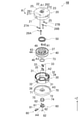
- FIG. 3 is an exploded perspective view of the cord holding device when the cord holding device according to the embodiment of the present invention is disassembled, as viewed from diagonally above.
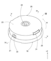
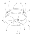
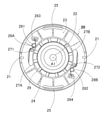
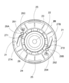
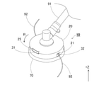
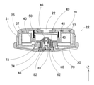
- FIG. 5 is an exploded perspective view of the cord holding device when the cord holding device according to the embodiment is disassembled, as viewed from diagonally below. It is a perspective view which looked at the cord holding device which concerns on embodiment from diagonally above. It is sectional drawing of the IV-IV cutting line shown in FIG. It is sectional drawing of the VV cutting line shown in FIG. It is a perspective view which looked at the cord holding device which concerns on embodiment from diagonally below. It is a bottom view of the cord holding device which concerns on embodiment.
- FIG. 1 It is a perspective view of the cord holding device when the slide piece provided in the cord holding device which concerns on embodiment is slid into the engaging recess. It is a bottom view of the upper case when the cord holding device which concerns on embodiment is stationary or is rotated at a low speed. It is a bottom view of the upper case when the cord holding device which concerns on embodiment rotates at high speed. It is a perspective view which shows the use state of the cord holding device which concerns on embodiment. It is sectional drawing in the use state of the cord holding apparatus which concerns on embodiment. It is sectional drawing of the code holding device when the cap and the protective cover are pushed up when the code holding device which concerns on embodiment rotates at a low speed. FIG.
- FIG. 3 is a cross-sectional view of another cutting line of the cord holding device when the cap and the protective cover are pushed up when the cord holding device according to the embodiment is rotated at a low speed. It is sectional drawing of the code holding device when the code holding device which concerns on embodiment rotates at high speed.
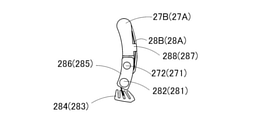
- FIG. 3 is a cross-sectional view of another cutting line of the cord holding device when the cap and the protective cover are pushed up when the cord holding device according to the embodiment rotates at high speed. It is a bottom view which shows the modification of the movable piece 27A, 27B provided in the cord holding device which concerns on embodiment.
- the code holding device according to the embodiment of the present invention will be described in detail with reference to the drawings.
- the same or equivalent parts are designated by the same reference numerals.
- the vertical direction is the Z direction.
- the clockwise direction is the rotation direction R of the rotation axis.
- the cord holding device is provided with a protective cover in order to prevent objects such as pebbles and soil from hitting the cord and scattering when the cord is rotated by the brush cutter.
- a switching mechanism for switching the winding function is provided. Further, this cord holding device includes a mechanism for limiting the cord feeding function during high-speed rotation.
- the cord holding device 10 includes an upper case 20, a lower case 30, a bobbin 40, a coil spring 50, a cap 60, and a protective cover 70.
- the upper case 20 is formed in a substantially cylindrical shape in which the cylindrical axis is directed in the vertical direction, the upper end side is closed by a disk, and the lower end side is open. Then, as shown in FIGS. 3 and 4, the upper case 20 is provided with a pair of cord outlets 21 on the cylindrical wall in order to pull out the cord wound around the bobbin 40 when the bobbin 40 is accommodated. ..
- the connection port 22 for inserting a bolt for attaching the rotation shaft of the brush cutter is a disk at the upper end of the cylinder, that is, the top plate portion. It has in 23. Its shape is circular, and its center is coaxial with the cylindrical axis A1 of the upper case 20.
- the cylindrical shaft A1 is flung with the central shaft of the rotary shaft, and the upper case 20 is made rotatable around the central shaft.
- the upper case 20 has a ring shape on the lower surface of the top plate portion 23 of the upper case 20 in order to control the rotation of the accommodated bobbin 40 when the upper case 20 is rotated by the rotation axis of the brush cutter.
- Each of the claws 24 has a shape having an inclined surface that becomes lower toward the rotation direction R and a vertical surface extending upward from the lower end of the inclined surface when viewed along the rotation direction R of the rotation axis of the brush cutter.
- the claws 24 are arranged along the circumference of a circle centered on the cylindrical axis A1.
- a plurality of claws 41 arranged in a ring shape are also provided on the upper surface of the bobbin 40.
- the claw 24 engages with the claw 41 on the upper surface of the bobbin 40 to control the rotation of the bobbin 40 in a specific case when the cord holding device 10 is rotated.
- the upper case 20 is provided with a pair of mounting holes 25 facing each other across the cylindrical shaft A1 at the upper part in the cylindrical wall.
- the lower case 30 is provided with a pair of hooks 31 facing each other with the cylindrical shaft A2 interposed therebetween and having the tips facing outward.
- the lower case 30 is fixed to the upper case 20 by hooking a pair of hooks 31 to the pair of mounting holes 25.
- the lower case 30 is a substantially cylindrical cylinder whose cylindrical axis is directed in the vertical direction, the upper end side is opened, and the lower end side is closed by a disk in order to cover the bobbin 40 from below. It is formed in a shape.
- the outer diameter of the cylinder is substantially the same as the inner diameter of the upper case 20.
- the lower case 30 is provided with a pair of cord outlets 32 on the cylindrical wall in order to pull out the cord from the bobbin 40 when assembled to the upper case 20. Then, a base 33 is fitted to each of the cord outlets 32, whereby damage to the cord is prevented.
- the lower case 30 when the lower case 30 is rotated by the rotation axis of the brush cutter, the rotation is transmitted to the bobbin 40, so that the lower case 30 is placed on the inner surface of the disk at the lower end of the cylinder of the lower case 30 as shown in FIG. That is, it has a plurality of claws 35 (also referred to as a first claw in the present specification) arranged in a ring shape on the upper surface of the bottom plate portion 34.
- claws 35 also referred to as a first claw in the present specification
- Each of the claws 35 has a shape having an inclined surface that becomes higher toward the rotation direction R and a vertical surface extending downward from the upper end of the inclined surface when viewed along the rotation direction R.
- the claws 35 are arranged along the circumference of a circle centered on the cylindrical axis A2 of the lower case 30.
- a plurality of claws 42 arranged in a ring shape are also provided on the lower surface of the bobbin 40.
- FIGS. 1 and 2 A circular through hole 36 is formed in which the axis overlaps with the cylindrical axis A2.
- the bobbin 40 is housed in the lower case 30.
- the bobbin 40 is formed in the shape of a cylinder in which flanges 43 and 44 protrude from the ends of the cylinder, respectively. Since its outer diameter is rotatable inside the lower case 30, it is slightly smaller than the inner diameter of the lower case 30, and its height is slightly smaller than the height of the internal space of the lower case 30. Then, as shown in FIG. 1, at the bottom of the cylindrical portion of the bobbin 40, a tubular portion 45 for passing a cord is formed so as to pass through the cylindrical axis A3 and cross the inner space of the cylinder. Further, the cylindrical portion is formed with a hole 46 for passing a cord penetrating the tubular portion 45. As a result, the bobbin 40 can wind the cord around the cylindrical portion after passing the cord through the tubular portion 45.
- the winding direction of the cord around the bobbin 40 is the rotation direction R of the rotating shaft in order to prevent the cord from loosening due to the rotation of the rotating shaft of the brush cutter.
- the rotation direction R is the winding direction of the cord and the opposite direction of the rotation direction R is the feeding direction of the cord.
- the bobbin 40 is housed in the internal space of the upper case 20 and the lower case 30 assembled to each other. At that time, the bobbin 40 is housed in the internal space together with the coil spring 50 in order to put the lower surface against the plurality of claws 35 (see FIG. 1) provided on the bottom plate portion 34 of the lower case 30.
- a circular groove 47 is formed at the upper end of the cylindrical portion of the bobbin 40 in order to determine the position of the coil spring 50.
- One end of the coil spring 50 is fitted in the groove 47.
- a groove 26 having a similar shape is formed in the top plate portion 23 of the upper case 20, and the other end of the coil spring 50 is fitted in the groove 26.
- the bobbin 40 and the lower case 30 sandwich the coil spring 50.
- the natural length of the coil spring 50 is larger than the distance from the groove 47 of the bobbin 40 to the groove 26 of the upper case 20, whereby the coil spring 50 is compressed in the internal space of the upper case 20 and the lower case 30. As a result, the bobbin 40 is pressed against the bottom plate portion 34 of the lower case 30. As a result, the lower surface of the bobbin 40 comes into contact with the bottom plate portion 34.
- a plurality of claws 42 (also referred to as a second claw in the present specification) arranged in a ring shape shown in FIG. 2 are provided on the lower surface of the bobbin 40. Since each of the claws 42 can engage with the claws 35 on the upper surface of the bottom plate portion 34 of the lower case 30, it is vertically symmetrical with each of the claws 35 and symmetrical in the rotation direction R. That is, when viewed along the rotation direction R, the shape has a vertical surface extending downward from the lower surface of the bobbin 40 and an inclined surface increasing from the lower end of the vertical surface toward the rotation direction R. And the arrangement of those claws 42 is the same as the arrangement of the claws 35. As a result, when the bobbin 40 is assembled to the upper case 20 and the lower case 30, the pressing force of the coil spring 50 is applied, so that the claw 42 engages with the claw 35.
- the vertical surface of the claw 42 is on the side of the vertical surface of the claw 35 in the rotation direction R as a result of the engagement between the claw 42 and the claw 35, and is adjacent to the vertical surface of the claw 35. Therefore, the bobbin 40 cannot rotate relative to the lower case 30 in the direction opposite to the rotation direction R. As a result, when the lower case 30 rotates in the rotation direction R, the bobbin 40 rotates in the rotation direction R at the same rotation speed as the lower case 30. As a result, the bobbin 40 does not rotate relative to the lower case 30 and does not pay out the cord. As a result, the length of the cord is preserved.
- a plurality of claws 41 arranged in a ring shape shown in FIG. 1 are provided on the upper surface of the bobbin 40. Since each of the claws 41 can engage with each of the claws 24 (see FIG. 2) on the lower surface of the top plate portion 23 of the upper case 20, it is vertically symmetrical with each of the claws 24 and symmetrical with respect to the rotation direction R. Further, the arrangement of the claws 41 is the same as the arrangement of the claws 24. As a result, the claw 41 can engage with the claw 24.
- the bobbin 40 is pressed against the bottom plate portion 34 of the lower case 30 by the coil spring 50. Therefore, the claw 41 of the bobbin 40 does not engage with the claw 24 of the upper case 20 unless a force for compressing the coil spring 50 is applied to the bobbin 40.
- the bobbin 40 if a force for compressing the coil spring 50 is applied to the bobbin 40, the bobbin 40 approaches the top plate portion 23 of the upper case 20, and as a result, the claw 41 of the bobbin 40 becomes the claw 24 of the upper case 20. Close to. At this time, the bobbin 40 is separated from the bottom plate portion 34 of the lower case 30, and the claw 42 on the lower surface of the bobbin 40 is disengaged from the claw 35 on the bottom plate portion 34 of the lower case 30. Therefore, when the lower case 30 is rotating in the rotation direction R, the bobbin 40 slows down more than the rotation speed of the lower case 30. As a result, the bobbin 40 rotates relative to the lower case 30 in the direction opposite to the rotation direction R.
- the above-mentioned bobbin 40 claw 41 slides along the above-mentioned inclined surface of the claw 24 of the upper case 20, which decreases toward the rotation direction R, while increasing in the opposite direction of the rotation direction R. do.
- the claw 41 of the bobbin 40 slides only up to the vertical surface of the bobbin 40 because the vertical surface of the adjacent claw 41 is adjacent to the inclined surface in the direction opposite to the rotation direction R.
- the bobbin 40 relatively moves in the direction opposite to the rotation direction R, that is, in the feeding direction of the cord, by the distance that the claw 41 of the bobbin 40 slides on the inclined surface of the claw 24 of the upper case 20.
- the bobbin 40 pays out the cord by that distance.
- a cap 60 is connected to the bobbin 40 in order to apply a force for compressing the coil spring 50 to feed out this cord.
- the cap 60 is given such a name because it closes the opening of the cover portion 72 of the protective cover 70, but the cap 60 not only closes the opening but also connects with the bobbin 40 to exert an external force. It is a member transmitted to the bobbin 40 (also referred to as a connecting member in the present specification).
- the cap 60 has a disk portion 61 arranged below the lower case 30 to receive an external force, and a pair of connecting claws 62 extending from the disk portion 61 to connect to the bobbin 40. ..
- the disk portion 61 is formed to have an outer diameter slightly smaller than the inner diameter of the central through hole formed in the cover portion 72. Although the details will be described later, the disk portion 61 is arranged in the through hole and closes the through hole. On the other hand, as shown in FIG. 2, a groove 65 for installing a switching mechanism 80, which will be described later, is formed on the lower surface of the disk portion 61. Further, on the upper surface of the disk portion 61, a pair of connecting claws 62 (also referred to as a connecting portion because they are connected to the bobbin 40 in the present specification) are provided in order to connect to the bobbin 40.
- Each of the connecting claws 62 has the shape of a hook having a protrusion protruding laterally at the tip of a rod-shaped portion extending upward. Then, the protrusion is directed radially and outward of the disk portion 61. Further, the connecting claws 62 are arranged so as to sandwich the disk shaft A4.
- a disk receiver 48 is provided which is formed in the shape of a small cylinder centered on the cylindrical shaft A3 and which protrudes downward from the lower surface of the bobbin 40. .. Further, as shown in FIG. 1, a pair of through holes 49 are formed at the bottom of the cylindrical portion of the bobbin 40 so as to sandwich the tubular portion 45 and to which the connecting claw 62 can be hooked. As shown in FIG. 5, the disk portion 61 is arranged in contact with the disk receiver 48. In this state, each of the connecting claws 62 is passed through a disk receiver 48 protruding downward from the through hole 36 of the lower case 30 and hooked on each of the through holes 49 of the bobbin 40. As a result, the cap 60 is connected to the bobbin 40. As a result, the cap 60 transmits the force applied to the bobbin 40.
- the cap 60 when the cap 60 is pushed from below, the bobbin 40 is pushed upward and a compressive force is applied to the coil spring 50. As a result, the claw 41 of the bobbin 40 shown in FIG. 1 is close to the claw 24 of the case 20 shown in FIG. 2, and the above-mentioned cord is fed out.
- the bobbin 40 is made to wind the cord. More specifically, when the cap 60 is not pushed from below, the coil spring 50 presses the bobbin 40 against the bottom plate portion 34 of the lower case 30, so that the claws 42 and 1 of the bobbin 40 shown in FIG. The claws 35 of the lower case 30 shown are engaged. At this time, although not shown, as described above, the vertical surface of the claw 42 of the bobbin 40 is on the side of the rotation direction R of the vertical surface of the claw 35 of the lower case 30 and is adjacent to the vertical surface of the claw 35.
- an inclined surface of the adjacent claw 35 that increases in the direction of the rotation direction R and a vertical surface downward from the upper end of the inclined surface are provided on the side of the claw 35 on the rotation direction R side of the vertical surface of the claw 35. ing. Therefore, the claw 42 of the bobbin 40 can slide along the inclined surface of the claw 35 adjacent to the side in the rotation direction R. In order to slide the claw 42 of the bobbin 40 in this way, the bobbin 40 is rotated relative to the lower case 30 in the rotation direction R. Therefore, when the rotation axis of the brush cutter is stopped, the cap 60 is rotated in the rotation direction R to rotate the bobbin 40 in the rotation direction R. As a result, the cap 60 causes the bobbin 40 to wind the cord.
- the cap 60 Since the cap 60 is connected to the bobbin 40, when the bobbin 40 is rotated by the rotation of the rotation shaft of the brush cutter, it rotates together with the bobbin 40. At this time, the lower case 30 also rotates. Therefore, while using the brush cutter, objects such as pebbles and soil (hereinafter, simply referred to as objects) may come into contact with the cap 60 and the lower case 30 and scatter around the brush cutter. In order to suppress this, a protective cover 70 is attached to the cap 60 as shown in FIGS. 4 and 5.
- the protective cover 70 has a shape with a hole in the center of the disk. Specifically, as shown in FIG. 1, the protective cover 70 has a cylindrical portion 71 and a disk-shaped cover portion 72 coaxial with the cylindrical portion 71 and having a through hole formed in the center.
- the cylindrical portion 71 is formed to have an outer diameter smaller than the inner diameter of the through hole 36 in the bottom plate portion 34 of the lower case 30.
- the upper portion of the cylindrical portion 71 is inserted into the through hole 36.
- the annulus member 73 is arranged on the lower surface of the bobbin 40.
- the annulus member 73 is made of a low friction resin, for example, polyacetal, and functions as a thrust bearing.
- the upper end of the cylindrical portion 71 is in contact with the annular member 73.
- the material of the annulus member 73 may be another resin such as polyamide or polytetrafluoroethylene.
- the inner wall of the cylindrical portion 71 is provided with a step in which the inner diameter on the upper side is small and the inner diameter on the lower side is large. Their inner diameters are significantly larger than the outer diameter of the disc receiver 48 of the bobbin 40, and the disc receiver 48 is inserted into the cylindrical portion 71.
- a cylindrical member 74 having a flange portion that fits into a step on the inner wall of the cylindrical portion 71 is inserted between the cylindrical portion 71 and the disk receiver 48.
- the cylindrical member 74 is a bush, that is, a slide bearing, which is made of the same low friction resin as the above-mentioned annular member 73.
- the cylindrical portion 71, the disk receiver 48, and the cylindrical member 74 have a gap between them to the extent that they can slide.
- the upper end of the cylindrical portion 71 is in contact with the annular member 73, and the inner wall of the cylindrical portion 71 is separated from the cylindrical member 74 by a slidable gap.
- the rotation of the bobbin 40 is less likely to be transmitted to the cylindrical portion 71.
- the cylindrical portion 71 can freely rotate and stand still regardless of the rotation.
- the cylindrical portion 71 can bring the claw 41 of the bobbin 40 and the claw 24 of the case 20 close to each other to feed out the above-mentioned cord.
- the cylindrical portion 71 extends downward from the through hole 36 in the bottom plate portion 34 of the lower case 30, and as a result, the lower portion of the cylindrical portion 71 protrudes below the lower case 30.
- the lower end of the cylindrical portion 71 is connected to the cover portion 72.
- the cover portion 72 is formed in the shape of a disk coaxial with the cylindrical shaft A5 of the cylindrical portion 71.
- a circular through hole is formed in the center of the cover portion 72, and the inner peripheral wall thereof is connected to the inner peripheral wall of the cylindrical portion 71.
- the disc portion 61 of the cap 60 described above is in contact with the flange portion of the cylindrical member 74 and the disc receiver 48 of the bobbin 40.
- the disk portion 61 holds the cylindrical member 74 after the position in the vertical direction is determined by the disk receiver 48.
- the disk portion 61 holds the cylindrical portion 71 of the protective cover 70 via the cylindrical member 74.
- the outer diameter of the disk portion 61 is slightly smaller than the inner diameter of the through hole of the cover portion 72. Therefore, even if the disk portion 61 of the cap 60 is rotated by the rotation of the bobbin 40 inside the through hole of the cover portion 72, the rotational force is not transmitted to the cover portion 72. As a result, the cover portion 72, like the cylindrical portion 71, can freely rotate and stand still even if the bobbin 40 rotates, regardless of the rotation. As a result, when the cover portion 72 hits an object during the cutting operation, it is difficult for the cover portion 72 to scatter the object.
- the disk portion 61 of the cap 60 inside the through hole of the cover portion 72 is provided with the slide piece 81 of the switching mechanism 80 described later, but the slide piece 81 protrudes outward from the through hole of the cover portion 72.
- the lower surface of the slide piece 81 is slightly recessed toward the inside of the through hole.
- the center of the disk portion 61 is slightly recessed toward the inside of the through hole, and the outer periphery thereof is at the same height as the cover portion 72 in the vertical direction.
- the outer diameter of the cover portion 72 is larger than that of the lower case 30, and the outer peripheral portion is located outside the lower case 30.
- the cover portion 72 is provided along the outer periphery and has an outer peripheral wall 75 surrounding the lower case 30. As a result, the cover portion 72 covers the lower case 30 from below. As a result, the scattering of objects such as pebbles and soil during the above-mentioned mowing work is suppressed.
- the cover portion 72 has a substantially flat central portion and has a shape that increases outward in the vicinity of the outer peripheral portion. As a result, it is easy to move along the ground during the mowing work, and it is easy to perform the mowing work.
- the cap 60 In the protective cover 70, the cap 60 is positioned inside the through hole of the cover portion 72 to make it difficult for an external object to hit. However, as it is, it is difficult to wind up the above-mentioned cord. This is because the cord is wound by rotating the cap 60 in the rotation direction R and rotating the bobbin 40 in the same direction as described above.
- the cap 60 is provided with a switching mechanism 80 for switching between a state of being connected to the protective cover 70 and a state of being released from the protective cover 70. Subsequently, in addition to FIGS. 1 to 5, the switching mechanism 80 will be described with reference to FIGS. 6 to 8.
- the switching mechanism 80 has a slide piece 81 provided on the disk portion 61 of the cap 60 and a leaf spring 82 that holds the slide piece at a specific position.
- the slide piece 81 is formed in the shape of a rectangular elongated plate. As described above, the groove 65 shown in FIG. 2 is formed on the lower surface of the disk portion 61 of the cap 60. The groove 65 has an elongated rectangular shape extending in the radial direction of the disk portion 61. The slide piece 81 is formed to have substantially the same shape as the groove 65 in the bottom view. Its thickness is approximately the same as the depth of the groove 65. The slide piece 81 is fitted in the groove 65 as shown in FIGS. 6 and 7. Further, the slide piece 81 can slide in the groove 65 in the longitudinal direction thereof. A mark indicating the slide direction is provided on the lower surface thereof for easy operation.
- the groove 65 has a step formed on the inner wall of the groove, and as a result, the groove width on the back side is wider than the groove width on the opening side. Since the slide piece 81 can be fitted into a groove having such a shape, the slide piece 81 has a step on the side wall surface, and the width of the slide piece 81 on the upper surface side in the lateral direction is wider than the width on the lower surface side. As a result, the slide piece 81 is prevented from falling off from the groove 65.
- a joint recess 76 (also referred to as a first recess in the present specification) is formed.
- the engaging recess 76 is recessed from the inner wall of the through hole of the cover portion 72 in the radial direction about the cylindrical axis A5 of the protective cover 70.
- the width of the engaging recess 76 is slightly larger than the width of the slide piece 81, and the length of the engaging recess 76 in the cylindrical axis A5 direction is slightly larger than the thickness of the end portion of the slide piece 81.
- the end portion of the slide piece 81 can enter the engaging recess 76.
- the switching mechanism 80 disconnects and disconnects the protective cover 70 and the cap 60 by the slide piece 81 entering the engaging recess 76 or the slide piece 81 retracting from the engaging recess 76. You can switch.
- the switching mechanism 80 connects the protective cover 70 and the cap 60 so that the cord can be wound, and the protective cover 70 is released from the cap 60 and the protective cover 70 suppresses the scattering of objects. And can be switched.
- the leaf spring 82 is formed in a linearly extending rod shape, with both ends bent upward and a central convex in which the rod is bent upward in a convex shape. Has a part. Then, as shown in FIG. 4, the leaf spring 82 is attached to the disc portion 61 by fixing both ends bent upward to the lower surface side of the disc portion 61 of the cap 60. Further, the slide piece 81 has a concave portion recessed downward from the upper surface in the center in the longitudinal direction, and the central convex portion of the leaf spring 82 does not allow the slide piece 81 to enter the engaging recess 76 of the protective cover 70.
- the leaf spring 82 When located in the center of the disk portion 61 of the cap 60, engages with the recess of the slide piece 81. Further, the leaf spring 82 presses the central convex portion against the concave portion of the slide piece 81 by its elastic force in a state where the central convex portion is engaged. As a result, the leaf spring 82 keeps the slide piece 81 in the center of the disk portion 61. As a result, the leaf spring 82 can maintain the state in which the slide piece 81 is retracted from the engaging recess 76, that is, the state in which the protective cover 70 and the cap 60 are disconnected. As a result, the leaf spring 82 maintains a state in which the protective cover 70 described above suppresses the scattering of the object. In other words, the leaf spring 82 prevents the protective cover 70 and the cap 60 from being inadvertently switched to the connected state.
- the cap 60 is directly connected to the bobbin 40, and the protective cover 70 is indirectly connected to the bobbin 40 via the annular member 73, the cylindrical member 74, and the cap 60. Therefore, the cord can be extended by pushing the cap 60 and the protective cover 70 upward with respect to the upper case 20 and the lower case 30 while the rotation shaft of the brush cutter is rotating. For example, the cord can be fed out by hitting the rotating cord holding device 10 against the ground during the cutting operation. However, if the cord holding device 10 is arranged at a position close to the ground and cutting is performed, the cord holding device 10 may accidentally hit the ground, and as a result, the cord may be unwound.
- the cord holding device 10 is equipped with a mechanism for restricting the feeding of the cord at the time of high-speed rotation (hereinafter referred to as a feeding limiting mechanism).
- a feeding limiting mechanism a mechanism for restricting the feeding of the cord at the time of high-speed rotation
- the payout limiting mechanism is connected to the movable pieces 27A and 27B housed in the upper case 20 and the movable pieces 27A and 27B shown in FIGS. 1 and 2, and is elastically deformed according to the centrifugal force due to the rotation of the cord holding device 10. It is composed of springs 28A and 28B that change the position of the movable piece.
- the movable pieces 27A and 27B are formed in the shape of a substantially rectangular plate, more specifically, a plate having a shape bent in an arc shape in the longitudinal direction.
- the movable pieces 27A and 27B have the plate surface oriented perpendicular to the cylindrical axis A1 of the upper case 20, and the side surface recessed in an arc shape directed toward the cylindrical axis A1.
- a wall portion 29 extending in a circular shape coaxial with the cylindrical axis A1 of the upper case 20 and surrounding the plurality of claws 24 is formed on the lower surface of the top plate portion 23 of the upper case 20. There is.
- the movable pieces 27A and 27B are arranged on the lower surface of the top plate portion 23 in a state of being in contact with the wall portion 29.
- the movable pieces 27A and 27B are fixed to the top plate 23 in a swingable state by inserting the protrusions 271 and 272 of the top plate 23 into the through holes formed at one end. There is.
- the springs 28A and 28B are parts also called urging bodies, and the movable pieces 27A and 27B are pressed against the wall portion 29 described above.
- the springs 28A and 28B are composed of torsion coil springs having arms extending from both ends of the coil portion. Then, one arm portion of the springs 28A and 28B passes from the coil portion through one end portion held by the protrusions 271 and 272 of the movable pieces 27A and 27B, and the other end on the opposite side to the one end portion. It extends to the part. Further, the other arm portion of the springs 28A and 28B is provided on the lower surface of the top plate portion 23 of the upper case 20 in a state of being elastically deformed with the space between the spring 28A and 28B being widened, and the movable pieces 27A and 27B.
- the coil portions of the springs 28A and 28B are provided on the lower surface of the top plate portion 23 and are screwed to the protrusions 281 and 282 adjacent to the protrusions 271 and 272 in the circumferential direction.
- the springs 28A and 28B urge the movable pieces 27A and 27B to keep them in contact with the wall portion 29 described above. Then, when the movable pieces 27A and 27B try to swing from the state of being in contact with the wall portion 29, an urging force corresponding to the swing angle is applied.
- the upper flange 43 of the bobbin 40 is provided with an edge portion 37 (also referred to as a protruding portion in the present specification) extending along the outer periphery and projecting upward. ing. Since the flange 43 is provided with the plurality of claws 41 described above, as a result, the flange 43 is relatively recessed between the edge portion 37 and the plurality of claws 41 as compared with the edge portion 37 and the plurality of claws 41. It will have a recess 38 (also referred to as a second recess in the present specification) shown in FIG.
- the movable pieces 27A and 27B are not located on the edge portion 37 when the cord holding device 10 is not rotating (hereinafter, simply referred to as a stationary state), and the movable pieces 27A and 27B are not located on the edge portion 37. It is located above the recess 38 between the claws 41. In other words, the movable pieces 27A and 27B are located in the region of the recess 38 between the edge 37 and the claw 41 in top view when stationary. The movable pieces 27A and 27B are located in the region of the recess 38 even when the cord holding device 10 is rotating at a low speed (hereinafter, simply referred to as a low speed rotation).
- the cap 60 and the protective cover 70 are not pushed up, and the bobbin 40 is pressed against the bottom plate portion 34 of the lower case 30 by the coil spring 50. It is formed in a shape having a thickness smaller than the height H in the vertical direction of the gap between the edge portion 37 and the lower surface of the top plate portion 23 of the upper case 20. Therefore, when the cap 60 and the protective cover 70 are pushed upward during low-speed rotation, the bobbin 40 tends to move away from the bottom plate portion 34 of the lower case 30 and rise toward the top plate portion 23 of the upper case 20.
- the movable pieces 27A and 27B relatively enter the recess 38 between the edge 37 on the flange 43 of the bobbin 40 and the claw 41.
- the movable pieces 27A and 27B do not prevent the bobbin 40 from rising.
- the bobbin 40 can rise away from the bottom plate portion 34 of the lower case 30.
- the claw 41 of the bobbin 40 is close to the claw 24 of the case 20, and the cord can be extended.
- the movable pieces 27A and 27B when the cord holding device 10 is rotating at high speed (hereinafter, simply referred to as high speed rotation), the movable pieces 27A and 27B have a large centrifugal force due to the high speed rotation, and as shown in FIG. It swings away from the wall portion 29 of the top plate portion 23 of the case 20 and swings at a certain swing angle or more. As a result, the movable pieces 27A and 27B, which are not shown in FIG. 10, are located on the edge portion 37. In other words, the movable pieces 27A and 27B overlap with the edge portion 37 when viewed from above.
- the cap 60 and the protective cover 70 are pushed upward during high-speed operation and the bobbin 40 tries to move away from the bottom plate portion 34 of the lower case 30 and rise toward the top plate portion 23 of the upper case 20, it is movable.
- the pieces 27A and 27B interfere with the edge 37, and the rise of the bobbin 40 is hindered. That is, the movable pieces 27A and 27B function as a stopper for the bobbin 40 to rise.
- the bobbin 40 cannot be separated from the bottom plate portion 34 of the lower case 30, and the cord cannot be extended.
- the fixing members 283 and 284 described above are provided with three recesses in order to adjust the magnitude of the urging force applied by the springs 28A and 28B to the movable pieces 27A and 27B. Then, one end of the two arms of the springs 28A and 28B is inserted and fixed in one of the three recesses. In FIGS. 9 and 10, the ends of the arms of the springs 28A and 28B are inserted and fixed in the central recess, but other recesses may be used.
- low-speed rotation means rotation in which the movable pieces 27A and 27B are located in the region of the recess 38 between the edge portion 37 and the claw 41 on the flange 43 of the bobbin 40 when viewed from above.
- the high-speed rotation means the rotation in which the movable pieces 27A and 27B overlap with the edge portion 37 of the flange 43 when viewed from above.
- connection port 22 of the upper case 20 is applied to the rotating shaft at the tip of the handle 91 of the brush cutter, and the upper case 20 is attached to the rotating shaft with bolts.
- the lower case 30 is assembled in a state in which parts such as the bobbin 40 and the coil spring 50 are housed in advance, and the cap 60, the protective cover 70 and the like are attached.
- the upper case 20 is attached to the rotating shaft
- the lower case 30 is attached to the upper case 20 to assemble the cord holding device 10.
- the slide piece 81 of the switching mechanism 80 is slid to engage the slide piece 81 with the engaging recess 76 of the protective cover 70 as shown in FIG.
- the cap 60 and the protective cover 70 are connected.
- the tip of the cord 92 is inserted from one of the cord outlets 21 of the upper case 20 into the hole 46 for passing the cord 92 of the bobbin 40.
- the tip of the cord 92 is pulled out from the other cord outlet 21.
- the protective cover 70 is rotated in the rotation direction R while holding the upper case 20. This causes the bobbin 40 to wind up the cord 92.
- the tip and end of the cord 92 are brought out from the cord outlet 21 by a certain length.
- the cap 60 connected to the bobbin 40 and the protective cover 70 are connected by the switching mechanism 80, it is sufficient to rotate the protective cover 70 having a large outer diameter, and as a result, the winding is performed with a small force. Can be done. Further, as a result of the large outer diameter, the protective cover 70 is easy to grasp and wind up.
- the slide piece 81 of the switching mechanism 80 is slid in the opposite direction, and the slide piece 81 is removed from the engaging recess 76 of the protective cover 70 as shown in FIGS. 6 and 7.
- the slide piece 81 is kept in a state where the slide piece 81 is disengaged from the engaging recess 76 due to the central convex portion of the leaf spring 82.
- the slide piece 81 does not move carelessly.
- the movable pieces 27A and 27B do not interfere with the edge portion 37 on the upper flange 43 of the bobbin 40.
- the claw 41 on the upper flange 43 of the bobbin 40 is close to the claw 24 of the upper case 20, which is not shown in FIG. 14, along the inclined surface of the claw 24 to the vertical surface of the adjacent claw 24. Since it moves, the code is paid out by the movement distance. The user of the brush cutter repeats this operation until the cord 92 has a desired length.
- FIG. 13 is a cross-sectional view when the cutting line is cut at the same position as the VV cutting line shown in FIG. 3, and FIG. 14 is a cutting line at the same position as the IV-IV cutting line shown in FIG. It is a cross-sectional view at the time of cutting in.
- FIGS. 15 and 16 described later are also cross-sectional views taken along the cutting line at the same position as the IV-IV cutting line.
- the cap 60 is provided on the disk portion 61 so as to be slidable in the radial direction of the disk portion 61, and slides in the radial direction and outward of the disk portion 61.
- the protective cover 70 is locked to the cover portion 72 to connect the disc portion 61 and the cover portion 72, and when the cover portion 72 is slid in the opposite direction, the disc portion 61 and the cover portion 72 are connected apart from the cover portion 72. It has a switching mechanism 80 for releasing the above.
- the switching mechanism 80 disengages the connection between the disk portion 61 and the cover portion 72 to cover the cover.
- the portion 72 can be separated from the disc portion 61 that rotates together with the upper case 20, the lower case 30, and the bobbin 40. As a result, it is possible to prevent the protective cover 70 from scattering objects such as pebbles and soil on the ground.
- the switching mechanism 80 when the user rotates the cover portion 72, the cap 60 having the disc portion 61 rotates the bobbin 40 to be connected. Can be done. As a result, the user can easily wind the cord around the bobbin 40.
- the bobbin 40 is provided on the outer peripheral side, and the edge portion 37 projecting upward and the recess portion recessed relatively downward from the tip of the edge portion 37 by projecting the edge portion 37 upward. 38, and there is a gap between the top plate portion 23 and the edge portion 37 of the upper case 20 in a state where the bobbin 40 is pressed against the bottom plate portion 34 of the lower case 30 by the coil spring 50.
- the upper case 20 is a movable piece 27A, 27B having a thickness in the vertical direction smaller than the height in the vertical direction of the gap, and moves according to the centrifugal force generated when the cord holding device 10 rotates. It has movable pieces 27A and 27B.
- the cord holding device 10 rotates at high speed, and the movable pieces 27A and 27B move due to the centrifugal force to enter the gap, so that the bobbin 40 by the cap 60 is removed from the bottom plate portion 34 of the lower case 30.
- Push-up can be restricted.
- the feeding of the cord is restricted at the time of high-speed rotation. This makes it possible to prevent an erroneous operation in which the cord is unwound by inadvertently pressing the cap 60 and the protective cover 70 during high-speed rotation.
- the present invention is not limited to this.
- the cap 60 closes the through hole of the cover portion 72 of the protective cover 70, but the present invention is not limited to this.
- the cap 60 may be connected to the bobbin 40 and connected to the bobbin 40, and does not need to close the through hole of the cover portion 72.
- the cap 60 may be referred to as a connecting member.
- the cap 60 has a connecting claw 62, it may be connected to the bobbin 40 by, for example, a screw or an adhesive instead of the connecting claw 62 because the cap 60 may be connected to the bobbin 40. ..
- the slide piece 81 has a plate shape, but in the present invention, the slide piece 81 is not limited to this. For example, it may have a shape called a block shape or a prismatic shape.
- the coil portions of the springs 28A and 28B are only fixed to the protrusions 281 and 282 by screws.
- the present invention is not limited to this.
- the coil portions of the springs 28A and 28B are screwed to the protrusions 281 and 282 via plate-shaped washers 285 and 286 that are bent in an arc shape in the longitudinal direction in order to improve stability. It may be stopped.
- the ends of the movable pieces 27A and 27B on the protrusions 271 and 272 side are recessed upward and have a flat shape, and the flat recesses may be covered by the washers 285 and 286 from below.
- the washer 285 and 286 may have their longitudinal directions oriented in the longitudinal direction of the movable pieces 27A and 27B. Further, the movable pieces 27A and 27B may have a recess along the arm portion of the springs 28A and 28B and protrusions 287 and 288 supporting the arm portion on the side surface bent in an arc shape. Thereby, when the movable pieces 27A and 27B swing due to the centrifugal force due to the rotation of the cord holding device 10, the swing can be stabilized.
- the bobbin, protective cover, switching mechanism, slide piece, upper case and elastic member can be referred to as a winding portion, a lower lid portion, a lock mechanism, a connecting piece, an upper lid portion and an urging body.
- a winding portion where the cord can be wound and the winding part
- the lower lid portion provided below the winding portion and A lock mechanism for switching between the connected state and the unconnected state of the wound portion and the lower lid portion,
- a cord holder for brush cutters characterized by being equipped with.
- the winding part where the cord can be wound and the winding part An upper lid portion provided above the winding portion and A cord holder for brush cutters equipped with The winding portion has an upwardly protruding edge portion and has an upwardly protruding edge portion.
- the upper lid portion has a movable piece and an urging body, and has a movable piece and an urging body. The movable piece is urged inward in the radial direction of the upper lid portion by the urging force of the urging body. The movable piece can move outward in the radial direction of the upper lid portion against the urging force of the urging body when the upper lid portion rotates.
- the cord holding device for a brush cutter wherein the green portion and the movable piece are positioned so that at least a part of the movable piece overlaps with each other in a plan view when the movable piece is moved outward in the radial direction of the upper lid portion.
- a lower lid portion provided below the winding portion is provided.
- Appendix 8 The base end of the movable piece is fixed to the upper lid portion and is fixed to the upper lid portion. The tip of the movable piece is urged inward in the radial direction of the upper lid portion by the urging force of the urging body. 6.
- Cord holder for brush cutters (Appendix 9) The cord holding device for a brush cutter according to any one of Supplementary note 6 to 8, wherein the movable piece has a shape having a plane parallel to a direction orthogonal to the rotation axis of the upper lid portion.
Landscapes
- Life Sciences & Earth Sciences (AREA)
- Environmental Sciences (AREA)
- Harvester Elements (AREA)
Abstract
A cord-holding device (10) that comprises an upper case (20), a cap (60), and a protective cover (70). The cap (60) has a switching mechanism (80) that: is provided to a disc part (61) so as to be capable of sliding in the radial direction of the disc part (61); engages a cover part (72) of the protective cover (70) upon sliding in the radial direction of the disc part (61) and toward the outside, thereby connecting the disc part (61) and the cover part (72); and separates from the cover part (72) upon sliding in the opposite direction, thereby releasing the connection between the disc part (61) and the cover part (72). The cord-holding device (10) is for holding string trimmer cord.
Description
本発明はコード保持装置に関する。
The present invention relates to a cord holding device.
コード保持装置は、刈払機が備える回転軸に取り付けられたときに、刈払機の刃として機能するコードを保持する装置である。このようなコード保持装置には、刈払機の回転軸が回転してコード保持装置が回転しているときに、コードが巻き付けられたボビンから延びる、そのコードの端部の長さを一定の長さに保つと共に、その長さを調整することができるものがある。
The cord holding device is a device that holds a cord that functions as a blade of the brush cutter when attached to the rotating shaft of the brush cutter. Such a cord holder has a constant length at the end of the cord that extends from the bobbin around which the cord is wound when the rotation axis of the brush cutter rotates and the cord holder rotates. There is something that can be kept and its length can be adjusted.
例えば、特許文献1には、上端が開放された円筒の形状に形成されたケースと、下面に円状に配列された複数の爪を有すると共に、ケースの上端を覆うキャップとを備え、ケースおよびキャップが形成する内部空間に、コードを巻き付け可能な円筒状のボビンおよび、ボビンに差し込まれた状態でボビンと連結すると共に、上端に複数の爪が配列された円筒状の爪車を収容するコード保持装置が開示されている。
For example, Patent Document 1 includes a case formed in the shape of a cylinder having an open upper end, a case having a plurality of claws arranged in a circle on the lower surface, and a cap covering the upper end of the case. A cord that accommodates a cylindrical bobbin around which a cord can be wound and a cylindrical bobbin with multiple claws arranged at the upper end while being connected to the bobbin while being inserted into the bobbin in the internal space formed by the cap. The holding device is disclosed.
特許文献1に記載のコード保持装置では、爪車の爪がキャップの複数の爪に係合することにより、爪車と連結するボビンがキャップと連結する。その結果、ボビンにコードが巻き付けられた状態で、刈払機の回転軸によってコード保持装置全体が回転するときでも、ボビンがキャップに対して相対的に回転しないので、ボビンから延びるコードの、ボビンから端部までの長さが保たれる。
In the cord holding device described in Patent Document 1, the claws of the claw wheel engage with a plurality of claws of the cap, so that the bobbin connected to the claw wheel is connected to the cap. As a result, even when the entire cord holding device is rotated by the rotation axis of the brush cutter with the cord wound around the bobbin, the bobbin does not rotate relative to the cap, so that the cord extending from the bobbin is rotated from the bobbin. The length to the end is maintained.
このコード保持装置全体が回転するときに、ケースの下面が物体、例えば、地面に叩きつけられると、その衝撃により、爪車の爪とキャップの複数の爪の係合が一時的に外れる。これにより、爪車とボビンが、一時的にキャップとケースの回転から切り離される。その結果、コードが一時的にボビンから繰り出される。このように、特許文献1に記載のコード保持装置では、ケースの叩きつけにより、コードの長さが調整される。
When the lower surface of the case is struck against an object, for example, the ground when the entire cord holding device is rotated, the impact causes the claws of the claw wheel and the plurality of claws of the cap to be temporarily disengaged. This temporarily separates the claw wheel and bobbin from the rotation of the cap and case. As a result, the code is temporarily ejected from the bobbin. As described above, in the cord holding device described in Patent Document 1, the length of the cord is adjusted by tapping the case.
また、特許文献2には、上端が開放され、下端中央に円形の貫通孔が開けられた円筒の形状のケースと、刈払機の回転軸が取り付けられると共に、ケースの上端を覆う上カバーとを備え、ケースと上カバーが形成する内部空間に、円筒部にコードが巻き付けられ、その円筒部の内周壁に周方向へ配列された複数の爪が設けられたボビンおよび、外周壁にボビンの複数の爪へ係合可能な別の複数の爪が設けられると共に、ケースの貫通孔とボビンの円筒部に差し込まれ、コイルばねによって下へ押圧された円筒状の押圧体を収容するコード保持装置が開示されている。
Further, in Patent Document 2, a cylindrical case having an open upper end and a circular through hole in the center of the lower end, a rotating shaft of a reaper, and an upper cover covering the upper end of the case are provided. A bobbin in which a cord is wound around a cylindrical portion in the internal space formed by the case and the upper cover, and a plurality of claws arranged in the circumferential direction are provided on the inner peripheral wall of the cylindrical portion, and a plurality of bobbins on the outer peripheral wall. A cord holding device that accommodates a cylindrical presser that is inserted into the through hole of the case and the cylindrical portion of the bobbin and pressed down by a coil spring, as well as multiple additional claws that can be engaged with the claws of the bobbin. It has been disclosed.
特許文献2に記載のコード保持装置では、押圧体が上述したコイルばねによって下へ押された状態で、押圧体の複数の爪がボビンの複数の爪に係合することにより、押圧体とボビンが連結する。一方、押圧体は、ケースの貫通孔内壁にある上下溝に緩挿された突起を有し、上カバーに刈払機の回転軸が取り付けられた状態で、回転軸が回転するときに、ケースと連動して回転する。その結果、ボビンがケースおよび押圧体と連動して回転する。これにより、回転時に、コードの、ボビンから端部までの長さが保たれる。
In the cord holding device described in Patent Document 2, the pressing body and the bobbin are formed by engaging the plurality of claws of the pressing body with the plurality of claws of the bobbin while the pressing body is pushed downward by the coil spring described above. Are connected. On the other hand, the pressing body has a protrusion loosely inserted in the upper and lower grooves on the inner wall of the through hole of the case, and when the rotating shaft rotates with the rotating shaft of the brush cutter attached to the upper cover, the case and the case It rotates in conjunction. As a result, the bobbin rotates in conjunction with the case and the pressing body. This keeps the length of the cord from the bobbin to the end during rotation.
一方、押圧体が物体、例えば、地面に押し付けられ、その押し付け力がコイルばねの押圧力よりも大きいと、押圧体がボビンに対して上へ相対移動する。その結果、押圧体の複数の爪がボビンの複数の爪から外れ、コードがボビンから繰り出される。特許文献2に記載のコード保持装置では、押圧体を物体に押し付けることにより、コードの長さが調整される。
On the other hand, when the pressing body is pressed against an object, for example, the ground, and the pressing force is larger than the pressing force of the coil spring, the pressing body moves upward relative to the bobbin. As a result, the plurality of claws of the pressing body are disengaged from the plurality of claws of the bobbin, and the cord is unwound from the bobbin. In the cord holding device described in Patent Document 2, the length of the cord is adjusted by pressing the pressing body against the object.
特許文献1に記載のコード保持装置では、刈払機の回転軸の回転によって回転するときに、ケースが回転してしまう。その結果、ユーザーが、コードを繰り出したいときに、ケースの下面を地面にたたきつけると、回転するケースが地面上の小石、土等の物体を飛散させてしまう。
In the code holding device described in Patent Document 1, the case rotates when it is rotated by the rotation of the rotation shaft of the brush cutter. As a result, when the user wants to pay out the cord, when the lower surface of the case is hit against the ground, the rotating case scatters objects such as pebbles and soil on the ground.
特許文献2に記載のコード保持装置でも、装置それ自体が回転するときに、押圧体が回転してしまい、回転する押圧体が地面上の小石、土等の物体を飛散させてしまう。
Even in the code holding device described in Patent Document 2, when the device itself rotates, the pressing body rotates, and the rotating pressing body scatters objects such as pebbles and soil on the ground.
また、特許文献1に記載のコード保持装置は、コードの繰り出しと巻き取りを可能にするため、カム機構を備える特殊なリングが設けられている。しかし、リングがキャップの下に配置されているため、刈払機の回転軸がキャップに取り付けられてしまうと、コードの繰り出しと巻き取りが難しい。
Further, the cord holding device described in Patent Document 1 is provided with a special ring provided with a cam mechanism in order to enable the cord to be unwound and wound. However, since the ring is located under the cap, it is difficult to unwind and wind the cord if the rotating shaft of the brush cutter is attached to the cap.
特許文献2に記載のコード保持装置は、押圧体を押し付けてコードを引っ張る作業を繰り返すことにより、コードの繰り出しを行うことが可能である。しかし、その作業は容易でない。さらに、コードの巻き取りを行うには、コード保持装置の分解が必要であり、その分解作業が容易でない。
The cord holding device described in Patent Document 2 can feed out the cord by repeating the work of pressing the pressing body and pulling the cord. However, the work is not easy. Further, in order to wind the cord, it is necessary to disassemble the cord holding device, and the disassembling work is not easy.
本発明は、上記の課題を解決するためになされたもので、刈払機の回転軸の回転によって回転するときに、小石、土等の物体がケースに当たって飛散することが抑制されたコード保持装置を提供することを目的とする。また、コードの繰り出しと巻き取りを容易に行うことができるコード保持装置を提供することを目的とする。
The present invention has been made to solve the above-mentioned problems, and is a cord holding device in which objects such as pebbles and soil are prevented from hitting the case and scattering when rotated by the rotation of the rotation axis of the brush cutter. The purpose is to provide. Another object of the present invention is to provide a cord holding device capable of easily feeding and winding a cord.
上記の目的を達成するため、本発明に係るコード保持装置は、
刈払機の回転軸が取り付けられる天板部と、前記回転軸が前記天板部に取り付けられたときの前記回転軸の中心軸と同軸となる位置に貫通孔が形成された底板部とを有し、前記底板部の上側の面には、複数の第一爪が設けられ、前記天板部と前記底板部との間にある内部空間には、前記複数の第一爪に係合可能な複数の第二爪を下側の面に有する、刈払機用コードが巻き付け可能なボビンが前記中心軸と同軸に収容され、前記ボビンがコイルばねにより前記底板部に押し付けられ、かつ前記複数の第二爪が前記複数の第一爪に係合することにより、前記ボビンと連結するケースと、
前記ボビンに接続され、前記ボビンから前記貫通孔を通って前記ケースの前記底板部よりも下へ延在する接続部と、該接続部の下端に設けられ、前記中心軸と同軸の円盤部とを有し、前記円盤部が前記ボビンのある側へ押されることにより、前記複数の第一爪と前記複数の第二爪が係合している場合のその係合を解除し、かつ前記円盤部が前記中心軸を中心に回転されることにより、前記ボビンを回転させる前記ボビンの連結部材と、
前記ボビンに回転可能に保持され、前記貫通孔に挿入されると共に前記貫通孔から前記ケースの前記底板部よりも下へ延在し、前記貫通孔内で前記中心軸と同軸に回転可能な円筒部であって、該円筒部に前記連結部材が挿入された前記円筒部と、前記円筒部の下端に支持され、前記ケースを下から覆うカバー部とを有する保護カバーと、
を備え、
前記連結部材は、前記円盤部に、前記円盤部の径方向へスライド可能に設けられ、前記円盤部の径方向かつ外側に向かってスライドした場合に、前記保護カバーの前記カバー部に係止して前記円盤部と前記カバー部を連結させ、逆方向にスライドした場合に、前記カバー部から離れて前記円盤部と前記カバー部の連結を解除する切り替え機構を有する、
前記刈払機用コードを保持するためのコード保持装置であることを特徴とする。 In order to achieve the above object, the code holding device according to the present invention is
It has a top plate portion to which the rotary shaft of the reaper is attached and a bottom plate portion having a through hole formed at a position coaxial with the central axis of the rotary shaft when the rotary shaft is attached to the top plate portion. A plurality of first claws are provided on the upper surface of the bottom plate portion, and the internal space between the top plate portion and the bottom plate portion can be engaged with the plurality of first claws. A bobbin having a plurality of second claws on the lower surface and around which a cord for a mowing machine can be wound is housed coaxially with the central axis, the bobbin is pressed against the bottom plate portion by a coil spring, and the plurality of second claws are provided. A case in which the two claws are engaged with the plurality of first claws to be connected to the bobbin.
A connection portion connected to the bobbin and extending from the bobbin through the through hole below the bottom plate portion of the case, and a disk portion provided at the lower end of the connection portion and coaxial with the central axis. When the disk portion is pushed to a certain side of the bobbin, the engagement of the plurality of first claws and the plurality of second claws is released, and the disk is disengaged. A connecting member of the bobbin that rotates the bobbin by rotating the portion about the central axis.
A cylinder that is rotatably held by the bobbin, inserted into the through hole, extends from the through hole below the bottom plate portion of the case, and can rotate coaxially with the central axis in the through hole. A protective cover having a cylindrical portion in which the connecting member is inserted into the cylindrical portion, and a cover portion supported by the lower end of the cylindrical portion and covering the case from below.
Equipped with
The connecting member is provided on the disk portion so as to be slidable in the radial direction of the disk portion, and when it slides in the radial direction and outward of the disk portion, it is locked to the cover portion of the protective cover. The disk portion and the cover portion are connected to each other, and when the cover portion is slid in the opposite direction, the disk portion and the cover portion are separated from the cover portion to release the connection between the disk portion and the cover portion.
It is a cord holding device for holding the cord for a brush cutter.
前記保護カバーは、前記カバー部に、前記カバー部の内周から外周の側へ凹む第一凹部を有し、
前記切り替え機構は、前記円盤部に、前記円盤部の径方向へスライド可能なスライド片を有し、
前記スライド片は、前記円盤部の径方向かつ外側に向かってスライドした場合に、スライド方向の側にある端部が前記第一凹部に入って前記スライド片がある前記円盤部を前記第一凹部がある前記カバー部に連結させてもよい。 The protective cover has a first recess in the cover portion that is recessed from the inner circumference to the outer peripheral side of the cover portion.
The switching mechanism has a slide piece that can slide in the radial direction of the disk portion in the disk portion.
When the slide piece slides in the radial direction and outward of the disk portion, the end portion on the slide direction side enters the first recess and the disk portion in which the slide piece is located is the first recess. It may be connected to the cover portion having a certain surface.
前記円盤部は、内部に前記スライド片を収容すると共に、円盤中心から外周まで延在し、その延在する方向に前記スライド片をスライド可能に保持する溝を有し、
前記スライド片の厚みは、前記溝の深さと同じであり、
前記円盤部は、前記カバー部と上下方向に同じ高さまたは、前記カバー部よりも上に位置するとよい。 The disk portion has a groove that accommodates the slide piece inside and extends from the center of the disk to the outer periphery and holds the slide piece slidably in the extending direction.
The thickness of the slide piece is the same as the depth of the groove,
The disk portion may be located at the same height as the cover portion in the vertical direction or above the cover portion.
前記カバー部は、その外周が前記ケースの外側に位置することにより、前記ケースに下から覆い被さってもよい。
The cover portion may be covered from below by the outer periphery thereof being located on the outside of the case.
前記ボビンは、外周側に設けられ、上へ突出する突出部と、前記突出部よりも内周側に設けられ、前記突出部が上へ突出することにより、前記突出部の突端よりも相対的に下に凹む第二凹部と、を有し、前記複数の第一爪と前記複数の第二爪が係合している状態で、前記ケースの前記天板部と前記突出部との間に隙間を有し、
前記ケースは、前記隙間の上下方向の高さよりも小さい上下方向の厚みを有し、前記回転軸が前記天板部に取り付けられ、回転したときに生じる遠心力に応じて移動する可動片を有し、
前記可動片は、前記回転軸が低速回転をしているときに、上面視で前記第二凹部の内部に位置することにより、前記連結部材による前記ボビンの前記底板部からの押し上げを制限せず、前記回転軸が高速回転をしているときに、上面視で前記突出部と重なる位置へ移動することにより、前記隙間に進入して前記連結部材による前記ボビンの前記底板部からの押し上げを制限してもよい。 The bobbin is provided on the outer peripheral side and protrudes upward, and is provided on the inner peripheral side of the protruding portion. By projecting the protruding portion upward, the bobbin is relative to the protruding end of the protruding portion. It has a second recess that is recessed downward, and in a state where the plurality of first claws and the plurality of second claws are engaged with each other, between the top plate portion and the protrusion portion of the case. Have a gap,
The case has a vertical thickness smaller than the vertical height of the gap, and has a movable piece that moves according to the centrifugal force generated when the rotating shaft is attached to the top plate portion and rotates. death,
The movable piece is located inside the second concave portion in a top view when the rotating shaft is rotating at a low speed, so that the movable piece does not limit the pushing up of the bobbin from the bottom plate portion by the connecting member. When the rotating shaft is rotating at high speed, the bobbin is moved to a position where it overlaps with the protruding portion in the top view to enter the gap and limit the pushing up of the bobbin from the bottom plate portion by the connecting member. You may.
前記ケースは、前記ケースの前記内部空間に配置され、一部分が前記天板部に固定され、該一部分から離れた他の部分が前記可動片の一端を支持する弾性部材をさらに有し、
前記可動片は、前記回転軸が前記天板部に取り付けられて回転したときに前記可動片に加わる遠心力が前記弾性部材を弾性変形させることにより、移動するとよい。 The case is disposed in the internal space of the case, one portion thereof is fixed to the top plate portion, and another portion away from the portion further has an elastic member supporting one end of the movable piece.
The movable piece may move by elastically deforming the elastic member by a centrifugal force applied to the movable piece when the rotating shaft is attached to the top plate portion and rotates.
前記ケースは、前記天板部から下に突出する壁部を有し、
前記弾性部材は、一端とコイル部が前記天板部に、他端が前記可動片に固定され、前記他端が前記可動片を前記壁部へ押し付けるコイルばねであり、
前記コイルばねは、前記回転軸による回転が行われず前記ケースが静止する場合に、前記可動片を前記壁部に当接させるとよい。 The case has a wall portion that protrudes downward from the top plate portion.
The elastic member is a coil spring in which one end and a coil portion are fixed to the top plate portion, the other end is fixed to the movable piece, and the other end presses the movable piece against the wall portion.
The coil spring may bring the movable piece into contact with the wall portion when the case is stationary without being rotated by the rotation shaft.
本発明の構成によれば、連結部材は、円盤部に、円盤部の径方向へスライド可能に設けられ、円盤部の径方向かつ外側に向かってスライドした場合に、保護カバーのカバー部に係止して円盤部とカバー部を連結させ、逆方向にスライドした場合に、カバー部から離れて円盤部とカバー部の連結を解除する切り替え機構を有する。このため、刈払機の回転軸がケースの天板部に取り付けられ、その回転軸が回転する場合に、切り替え機構によって円盤部とカバー部の連結を解除することにより、カバー部を、ケースおよびボビンと共に回転する円盤部から切り離すことができる。その結果、カバー部が地面上の小石、土等の物体を飛散させることを抑制することができる。
According to the configuration of the present invention, the connecting member is provided on the disk portion so as to be slidable in the radial direction of the disk portion, and is engaged with the cover portion of the protective cover when the disk portion is slid in the radial direction and outward. It has a switching mechanism that stops and connects the disk portion and the cover portion, and when it slides in the opposite direction, it separates from the cover portion and releases the connection between the disk portion and the cover portion. Therefore, when the rotating shaft of the brush cutter is attached to the top plate of the case and the rotating shaft rotates, the cover is connected to the case and bobbin by disconnecting the disk and the cover by the switching mechanism. It can be separated from the disk part that rotates with it. As a result, it is possible to prevent the cover portion from scattering objects such as pebbles and soil on the ground.
また、切り替え機構によって円盤部とカバー部を連結させることにより、ユーザーがカバー部を回動させたときに、円盤部を有する連結部材と連結するボビンを回動させることができる。その結果、ユーザーは、容易にコードをボビンから繰り出したり、コードをボビンに巻き取ったりすることができる。
Further, by connecting the disk portion and the cover portion by the switching mechanism, when the user rotates the cover portion, the bobbin connected to the connecting member having the disk portion can be rotated. As a result, the user can easily pull the cord out of the bobbin and wind the cord onto the bobbin.
以下、本発明の実施の形態に係るコード保持装置について図面を参照して詳細に説明する。なお、図中、同一又は同等の部分には同一の符号を付す。また、図中、回転軸を下に向けた刈払機にコード保持装置を取り付けた場合の、上下方向がZ方向である。また、回転軸を下に向けた刈払機を下から見たときの、時計回りが回転軸の回転方向Rである。
Hereinafter, the code holding device according to the embodiment of the present invention will be described in detail with reference to the drawings. In the figure, the same or equivalent parts are designated by the same reference numerals. Further, in the figure, when the cord holding device is attached to the brush cutter with the rotation axis facing downward, the vertical direction is the Z direction. Further, when the brush cutter with the rotation axis facing downward is viewed from below, the clockwise direction is the rotation direction R of the rotation axis.
実施の形態に係るコード保持装置は、刈払機による回転時、コードに小石、土等の物体が当たって飛散することを抑制するため、保護カバーを備えるところ、その保護カバーにコードの繰り出し機能と巻き取り機能を切り替える切り替え機構が設けられている。また、このコード保持装置は、高速回転時にコードの繰り出し機能を制限する機構を備える。まず、図1-図5を参照して、コード保持装置の構成について説明する。その後、切り替え機構とコードの繰り出し機能を制限する機構について説明する。
The cord holding device according to the embodiment is provided with a protective cover in order to prevent objects such as pebbles and soil from hitting the cord and scattering when the cord is rotated by the brush cutter. A switching mechanism for switching the winding function is provided. Further, this cord holding device includes a mechanism for limiting the cord feeding function during high-speed rotation. First, the configuration of the code holding device will be described with reference to FIGS. 1 to 5. After that, the switching mechanism and the mechanism for limiting the code feeding function will be described.
(コード保持装置の構成)
図1および図2に示すように、コード保持装置10は、上ケース20、下ケース30、ボビン40、コイルばね50、キャップ60および、保護カバー70により構成されている。 (Configuration of code holder)
As shown in FIGS. 1 and 2, thecord holding device 10 includes an upper case 20, a lower case 30, a bobbin 40, a coil spring 50, a cap 60, and a protective cover 70.
図1および図2に示すように、コード保持装置10は、上ケース20、下ケース30、ボビン40、コイルばね50、キャップ60および、保護カバー70により構成されている。 (Configuration of code holder)
As shown in FIGS. 1 and 2, the
上ケース20は、ボビン40を上から覆うため、円筒軸が上下方向に向けられ、上端側が円板により閉鎖されると共に、下端側が開放された略円筒の形状に形成されている。そして、図3および図4に示すように、上ケース20は、ボビン40を収容したときに、ボビン40に巻き付けられたコードを引き出すため、円筒壁に一対のコード引出口21が設けられている。
In order to cover the bobbin 40 from above, the upper case 20 is formed in a substantially cylindrical shape in which the cylindrical axis is directed in the vertical direction, the upper end side is closed by a disk, and the lower end side is open. Then, as shown in FIGS. 3 and 4, the upper case 20 is provided with a pair of cord outlets 21 on the cylindrical wall in order to pull out the cord wound around the bobbin 40 when the bobbin 40 is accommodated. ..
また、上ケース20は、コード引出口21からコードを引き出した状態で回転させるため、刈払機の回転軸を取り付けるボルトを入れるための接続口22を円筒上端にある円板、すなわち、天板部23に有する。その形状は、円状であり、その中心は、上ケース20の円筒軸A1と同軸である。これにより、上ケース20は、刈払機の回転軸が取り付けられたときに、円筒軸A1が回転軸の中心軸とあわされ、その中心軸の回りに回転可能にされている。
Further, since the upper case 20 is rotated in a state where the cord is pulled out from the cord outlet 21, the connection port 22 for inserting a bolt for attaching the rotation shaft of the brush cutter is a disk at the upper end of the cylinder, that is, the top plate portion. It has in 23. Its shape is circular, and its center is coaxial with the cylindrical axis A1 of the upper case 20. As a result, in the upper case 20, when the rotary shaft of the brush cutter is attached, the cylindrical shaft A1 is flung with the central shaft of the rotary shaft, and the upper case 20 is made rotatable around the central shaft.
さらに、上ケース20は、図2に示すように、刈払機の回転軸により回転するときに、収容したボビン40の回転を制御するため、上ケース20の天板部23の下面に、リング状に配列された複数の爪24を有する。
Further, as shown in FIG. 2, the upper case 20 has a ring shape on the lower surface of the top plate portion 23 of the upper case 20 in order to control the rotation of the accommodated bobbin 40 when the upper case 20 is rotated by the rotation axis of the brush cutter. Has a plurality of claws 24 arranged in.
爪24それぞれは、刈払機の回転軸の回転方向Rに沿って見た場合に、回転方向Rに向かうに従い低くなっていく傾斜面とその傾斜面の下端から上へ延びる鉛直面とを有する形状を有する。そして、それらの爪24は、円筒軸A1を中心とする円の周に沿って配列されている。ボビン40の上面にも、図1に示すように、リング状に配列された複数の爪41が設けられている。詳細な内容は後述するが、爪24は、コード保持装置10の回転時の特定の場合に、ボビン40の上面の爪41と係合して、ボビン40の回転を制御する。
Each of the claws 24 has a shape having an inclined surface that becomes lower toward the rotation direction R and a vertical surface extending upward from the lower end of the inclined surface when viewed along the rotation direction R of the rotation axis of the brush cutter. Has. The claws 24 are arranged along the circumference of a circle centered on the cylindrical axis A1. As shown in FIG. 1, a plurality of claws 41 arranged in a ring shape are also provided on the upper surface of the bobbin 40. Although the details will be described later, the claw 24 engages with the claw 41 on the upper surface of the bobbin 40 to control the rotation of the bobbin 40 in a specific case when the cord holding device 10 is rotated.
また、上ケース20は、図5に示すように、円筒壁内の上部に、円筒軸A1を挟んで対向する一対の取り付け孔25が設けられている。これに対して、下ケース30には、円筒壁内の上部に円筒軸A2を挟んで対向し、先端が外側へ向いた一対のフック31が設けられている。上ケース20には、一対の取り付け孔25に一対のフック31が掛止することにより、下ケース30が固定されている。
Further, as shown in FIG. 5, the upper case 20 is provided with a pair of mounting holes 25 facing each other across the cylindrical shaft A1 at the upper part in the cylindrical wall. On the other hand, the lower case 30 is provided with a pair of hooks 31 facing each other with the cylindrical shaft A2 interposed therebetween and having the tips facing outward. The lower case 30 is fixed to the upper case 20 by hooking a pair of hooks 31 to the pair of mounting holes 25.
下ケース30は、図1および図2に示すように、ボビン40を下から覆うため、円筒軸が上下方向に向けられ、上端側が開放されると共に、下端側が円板により閉鎖された略円筒の形状に形成されている。その円筒の外径は、上ケース20の内径とほぼ同径である。これにより、下ケース30は、上ケース20に嵌め込み可能である。その結果、下ケース30は、上ケース20の開放された円筒端に嵌め込まれて組み付けられる。
As shown in FIGS. 1 and 2, the lower case 30 is a substantially cylindrical cylinder whose cylindrical axis is directed in the vertical direction, the upper end side is opened, and the lower end side is closed by a disk in order to cover the bobbin 40 from below. It is formed in a shape. The outer diameter of the cylinder is substantially the same as the inner diameter of the upper case 20. As a result, the lower case 30 can be fitted into the upper case 20. As a result, the lower case 30 is fitted and assembled to the open cylindrical end of the upper case 20.
下ケース30は、上ケース20に組み付けられたときに、ボビン40からコードを引き出すため、一対のコード引出口32が円筒壁に設けられている。そして、コード引出口32それぞれには、口金33が嵌められ、これにより、コードの破損が防止される。
The lower case 30 is provided with a pair of cord outlets 32 on the cylindrical wall in order to pull out the cord from the bobbin 40 when assembled to the upper case 20. Then, a base 33 is fitted to each of the cord outlets 32, whereby damage to the cord is prevented.
また、下ケース30は、刈払機の回転軸によって回転するときに、その回転をボビン40に伝動するため、図1に示すように、下ケース30の円筒下端にある円板の内側の面に、すなわち、底板部34の上面に、リング状に配列された複数の爪35(本明細書では第一爪ともいう)を有する。
Further, when the lower case 30 is rotated by the rotation axis of the brush cutter, the rotation is transmitted to the bobbin 40, so that the lower case 30 is placed on the inner surface of the disk at the lower end of the cylinder of the lower case 30 as shown in FIG. That is, it has a plurality of claws 35 (also referred to as a first claw in the present specification) arranged in a ring shape on the upper surface of the bottom plate portion 34.
爪35それぞれは、回転方向Rに沿って見た場合に、回転方向Rに向かうに従い高くなっていく傾斜面とその傾斜面の上端から下へ延びる鉛直面とを有する形状を有する。それらの爪35は、下ケース30の円筒軸A2を中心とする円の周に沿って配列されている。これに対して、ボビン40の下面にも、図2に示すように、リング状に配列された複数の爪42が設けられている。詳細な内容は後述するが、爪35は、コード保持装置10の回転時にボビン40の爪42と係合して、下ケース30の回転をボビン40に伝動する。
Each of the claws 35 has a shape having an inclined surface that becomes higher toward the rotation direction R and a vertical surface extending downward from the upper end of the inclined surface when viewed along the rotation direction R. The claws 35 are arranged along the circumference of a circle centered on the cylindrical axis A2 of the lower case 30. On the other hand, as shown in FIG. 2, a plurality of claws 42 arranged in a ring shape are also provided on the lower surface of the bobbin 40. Although the details will be described later, the claw 35 engages with the claw 42 of the bobbin 40 when the cord holding device 10 rotates, and transmits the rotation of the lower case 30 to the bobbin 40.
一方、ボビン40の下側には、キャップ60が取り付けられるところ、そのキャップ60を下ケース30の下側へ突出させるため、下ケース30の底板部34に、図1および図2に示すように、円筒軸A2と軸線が重なる円形の貫通孔36が形成されている。そして、下ケース30には、ボビン40が収容される。
On the other hand, where the cap 60 is attached to the lower side of the bobbin 40, in order to project the cap 60 to the lower side of the lower case 30, the bottom plate portion 34 of the lower case 30 is shown in FIGS. 1 and 2. , A circular through hole 36 is formed in which the axis overlaps with the cylindrical axis A2. The bobbin 40 is housed in the lower case 30.
ボビン40は、円筒端それぞれからフランジ43、44が出っ張った円筒の形状に形成されている。その外径は、下ケース30内で回転可能とするため、下ケース30の内径よりもやや小さく、高さは、下ケース30の内部空間の高さよりもやや小さい。そして、図1に示すように、ボビン40の円筒部の底には、円筒軸A3を通って円筒内部空間を横断する、コードを通すための管状部45が形成されている。さらに、円筒部には、その管状部45を貫通するコードを通すための孔46が形成されている。これにより、ボビン40は、コードを管状部45に通した後、円筒部にコードを巻き付けることが可能である。
The bobbin 40 is formed in the shape of a cylinder in which flanges 43 and 44 protrude from the ends of the cylinder, respectively. Since its outer diameter is rotatable inside the lower case 30, it is slightly smaller than the inner diameter of the lower case 30, and its height is slightly smaller than the height of the internal space of the lower case 30. Then, as shown in FIG. 1, at the bottom of the cylindrical portion of the bobbin 40, a tubular portion 45 for passing a cord is formed so as to pass through the cylindrical axis A3 and cross the inner space of the cylinder. Further, the cylindrical portion is formed with a hole 46 for passing a cord penetrating the tubular portion 45. As a result, the bobbin 40 can wind the cord around the cylindrical portion after passing the cord through the tubular portion 45.
なお、ボビン40へのコードの巻き付け方向は、刈払機の回転軸が回転することにより、コードが緩むことを防ぐため、回転軸の回転方向Rである。以下、回転方向Rがコードの巻き付け方向であり、回転方向Rの逆方向がコードの繰り出し方向であることを前提に説明する。
The winding direction of the cord around the bobbin 40 is the rotation direction R of the rotating shaft in order to prevent the cord from loosening due to the rotation of the rotating shaft of the brush cutter. Hereinafter, it is assumed that the rotation direction R is the winding direction of the cord and the opposite direction of the rotation direction R is the feeding direction of the cord.
ボビン40は、図4および図5に示すように、互いに組み付けられた上ケース20および下ケース30の内部空間に収容される。そのとき、ボビン40は、下面を、下ケース30の底板部34に設けられた、上述した複数の爪35(図1参照)に当てるため、コイルばね50と共に、その内部空間に収容される。ボビン40の円筒部上端には、そのコイルばね50の位置を決めるため、円状の溝47が形成されている。そして、その溝47には、コイルばね50の一端が嵌められている。これに対して、上ケース20の天板部23には、同様の形状の溝26が形成され、その溝26にコイルばね50の他端が嵌められている。これらにより、ボビン40と下ケース30は、コイルばね50を挟持する。
As shown in FIGS. 4 and 5, the bobbin 40 is housed in the internal space of the upper case 20 and the lower case 30 assembled to each other. At that time, the bobbin 40 is housed in the internal space together with the coil spring 50 in order to put the lower surface against the plurality of claws 35 (see FIG. 1) provided on the bottom plate portion 34 of the lower case 30. A circular groove 47 is formed at the upper end of the cylindrical portion of the bobbin 40 in order to determine the position of the coil spring 50. One end of the coil spring 50 is fitted in the groove 47. On the other hand, a groove 26 having a similar shape is formed in the top plate portion 23 of the upper case 20, and the other end of the coil spring 50 is fitted in the groove 26. As a result, the bobbin 40 and the lower case 30 sandwich the coil spring 50.
コイルばね50の自然長は、ボビン40の溝47から上ケース20の溝26までの距離よりも大きく、これにより、コイルばね50は、上ケース20および下ケース30の内部空間で圧縮される。その結果、ボビン40は、下ケース30の底板部34に押し付けられる。これにより、ボビン40の下面が底板部34に当接する。
The natural length of the coil spring 50 is larger than the distance from the groove 47 of the bobbin 40 to the groove 26 of the upper case 20, whereby the coil spring 50 is compressed in the internal space of the upper case 20 and the lower case 30. As a result, the bobbin 40 is pressed against the bottom plate portion 34 of the lower case 30. As a result, the lower surface of the bobbin 40 comes into contact with the bottom plate portion 34.
ボビン40の下面には、上述したように、図2に示すリング状に配列された複数の爪42(本明細書では第二爪ともいう)が設けられている。爪42それぞれは、下ケース30の底板部34の上面にある爪35と係合可能とするため、爪35それぞれと上下対称かつ、回転方向Rに対称である。すなわち、回転方向Rに沿って見た場合に、ボビン40の下面から下へ延びる鉛直面とその鉛直面の下端から回転方向Rに向かうに従い高くなっていく傾斜面とを有する形状である。そして、それらの爪42の配列は、爪35の配列と同じである。その結果、ボビン40が上ケース20および下ケース30に組み付けられると、コイルばね50の押し付け力が加わるため、爪42は、爪35と係合する。
As described above, a plurality of claws 42 (also referred to as a second claw in the present specification) arranged in a ring shape shown in FIG. 2 are provided on the lower surface of the bobbin 40. Since each of the claws 42 can engage with the claws 35 on the upper surface of the bottom plate portion 34 of the lower case 30, it is vertically symmetrical with each of the claws 35 and symmetrical in the rotation direction R. That is, when viewed along the rotation direction R, the shape has a vertical surface extending downward from the lower surface of the bobbin 40 and an inclined surface increasing from the lower end of the vertical surface toward the rotation direction R. And the arrangement of those claws 42 is the same as the arrangement of the claws 35. As a result, when the bobbin 40 is assembled to the upper case 20 and the lower case 30, the pressing force of the coil spring 50 is applied, so that the claw 42 engages with the claw 35.
図示しないが、爪42の鉛直面は、爪42と爪35が係合する結果、爪35の鉛直面の、回転方向Rの側にあり、爪35の鉛直面に隣接する。このため、ボビン40は、下ケース30に対して回転方向Rの逆方向には相対的に回転できない。その結果、ボビン40は、下ケース30が回転方向Rに回転した場合に、回転方向Rに下ケース30と同じ回転速度で回転する。これにより、ボビン40は、下ケース30に対して相対的に回転せず、コードを繰り出すことがない。その結果、コードの長さが保たれる。
Although not shown, the vertical surface of the claw 42 is on the side of the vertical surface of the claw 35 in the rotation direction R as a result of the engagement between the claw 42 and the claw 35, and is adjacent to the vertical surface of the claw 35. Therefore, the bobbin 40 cannot rotate relative to the lower case 30 in the direction opposite to the rotation direction R. As a result, when the lower case 30 rotates in the rotation direction R, the bobbin 40 rotates in the rotation direction R at the same rotation speed as the lower case 30. As a result, the bobbin 40 does not rotate relative to the lower case 30 and does not pay out the cord. As a result, the length of the cord is preserved.
また、ボビン40の上面には、上述したように、図1に示すリング状に配列された複数の爪41が設けられている。爪41それぞれは、上ケース20の天板部23の下面にある爪24それぞれ(図2参照)と係合可能とするため、爪24それぞれと上下対称かつ、回転方向Rに対称である。また、爪41の配列は、爪24の配列と同じである。その結果、爪41は、爪24と係合することが可能である。
Further, as described above, a plurality of claws 41 arranged in a ring shape shown in FIG. 1 are provided on the upper surface of the bobbin 40. Since each of the claws 41 can engage with each of the claws 24 (see FIG. 2) on the lower surface of the top plate portion 23 of the upper case 20, it is vertically symmetrical with each of the claws 24 and symmetrical with respect to the rotation direction R. Further, the arrangement of the claws 41 is the same as the arrangement of the claws 24. As a result, the claw 41 can engage with the claw 24.
ボビン40は、コイルばね50によって下ケース30の底板部34に押し付けられている。このため、ボビン40の爪41は、コイルばね50を圧縮する力がボビン40に加わらない限り、上ケース20の爪24に係合しない。
The bobbin 40 is pressed against the bottom plate portion 34 of the lower case 30 by the coil spring 50. Therefore, the claw 41 of the bobbin 40 does not engage with the claw 24 of the upper case 20 unless a force for compressing the coil spring 50 is applied to the bobbin 40.
図示しないが、仮に、コイルばね50を圧縮する力がボビン40に加わった場合、ボビン40が上ケース20の天板部23に近づき、その結果、ボビン40の爪41が上ケース20の爪24に近接する。このとき、ボビン40が下ケース30の底板部34から離れ、ボビン40の下面にある爪42が下ケース30の底板部34にある爪35から外れる。このため、ボビン40は、下ケース30が回転方向Rへ回転している場合、下ケース30の回転速度よりも減速する。その結果、ボビン40は、下ケース30に対して回転方向Rの逆方向へ相対的に回転する。この場合、上述したボビン40の爪41は、上ケース20の爪24の上述した、回転方向Rに向かうに従い低くなっていく傾斜面に沿って、回転方向Rの逆方向へ高くなりながら摺動する。このとき、ボビン40の爪41は、その傾斜面と回転方向Rの逆方向に隣の爪41の鉛直面が隣接するため、その鉛直面までしか摺動しない。これにより、ボビン40は、回転方向Rの逆方向へ、すなわち、コードの繰り出し方向へ、ボビン40の爪41が上ケース20の爪24の傾斜面を摺動する距離だけ相対的に移動する。その結果、ボビン40は、コードをその距離だけ繰り出す。
Although not shown, if a force for compressing the coil spring 50 is applied to the bobbin 40, the bobbin 40 approaches the top plate portion 23 of the upper case 20, and as a result, the claw 41 of the bobbin 40 becomes the claw 24 of the upper case 20. Close to. At this time, the bobbin 40 is separated from the bottom plate portion 34 of the lower case 30, and the claw 42 on the lower surface of the bobbin 40 is disengaged from the claw 35 on the bottom plate portion 34 of the lower case 30. Therefore, when the lower case 30 is rotating in the rotation direction R, the bobbin 40 slows down more than the rotation speed of the lower case 30. As a result, the bobbin 40 rotates relative to the lower case 30 in the direction opposite to the rotation direction R. In this case, the above-mentioned bobbin 40 claw 41 slides along the above-mentioned inclined surface of the claw 24 of the upper case 20, which decreases toward the rotation direction R, while increasing in the opposite direction of the rotation direction R. do. At this time, the claw 41 of the bobbin 40 slides only up to the vertical surface of the bobbin 40 because the vertical surface of the adjacent claw 41 is adjacent to the inclined surface in the direction opposite to the rotation direction R. As a result, the bobbin 40 relatively moves in the direction opposite to the rotation direction R, that is, in the feeding direction of the cord, by the distance that the claw 41 of the bobbin 40 slides on the inclined surface of the claw 24 of the upper case 20. As a result, the bobbin 40 pays out the cord by that distance.
図1および図2に戻って、コイルばね50を圧縮する力を加えて、このコードの繰り出しを行うため、ボビン40には、キャップ60が連結される。
Returning to FIGS. 1 and 2, a cap 60 is connected to the bobbin 40 in order to apply a force for compressing the coil spring 50 to feed out this cord.
キャップ60は、保護カバー70が有するカバー部72の開口を塞ぐため、このような名称が付けられているが、キャップ60は、開口を塞ぐだけでなく、ボビン40と連結して外部の力をボビン40に伝達する部材である(なお、本明細書では連結部材ともいう)。キャップ60は、外部の力を受けるため、下ケース30よりも下に配置される円盤部61と、円盤部61から延在する、ボビン40と連結させるための一対の連結爪62と、を有する。
The cap 60 is given such a name because it closes the opening of the cover portion 72 of the protective cover 70, but the cap 60 not only closes the opening but also connects with the bobbin 40 to exert an external force. It is a member transmitted to the bobbin 40 (also referred to as a connecting member in the present specification). The cap 60 has a disk portion 61 arranged below the lower case 30 to receive an external force, and a pair of connecting claws 62 extending from the disk portion 61 to connect to the bobbin 40. ..
円盤部61は、カバー部72に形成された中央の貫通孔の内径よりもやや小さい外径に形成されている。詳細な内容は後述するが、円盤部61は、その貫通孔に配置され、その貫通孔を塞ぐ。一方、円盤部61の下面には、図2に示すように、後述する切り替え機構80を設置するための溝65が形成されている。また、円盤部61の上面には、ボビン40に連結するため、一対の連結爪62(本明細書ではボビン40と接続されるため接続部ともいう)が設けられている。
The disk portion 61 is formed to have an outer diameter slightly smaller than the inner diameter of the central through hole formed in the cover portion 72. Although the details will be described later, the disk portion 61 is arranged in the through hole and closes the through hole. On the other hand, as shown in FIG. 2, a groove 65 for installing a switching mechanism 80, which will be described later, is formed on the lower surface of the disk portion 61. Further, on the upper surface of the disk portion 61, a pair of connecting claws 62 (also referred to as a connecting portion because they are connected to the bobbin 40 in the present specification) are provided in order to connect to the bobbin 40.
連結爪62それぞれは、上方に延在する棒状部分の先端に側方へ突出する突起があるフックの形状を有する。そして、その突起を円盤部61の径方向かつ外側に向けている。また、連結爪62同士は、円盤軸A4を挟んで配列されている。
Each of the connecting claws 62 has the shape of a hook having a protrusion protruding laterally at the tip of a rod-shaped portion extending upward. Then, the protrusion is directed radially and outward of the disk portion 61. Further, the connecting claws 62 are arranged so as to sandwich the disk shaft A4.
図2に示すように、ボビン40の下面の側には、円筒軸A3を軸とする小円筒の形状に形成されると共に、ボビン40の下面から下へ突出した円盤受け48が設けられている。また、図1に示すように、ボビン40の円筒部の底には、管状部45を挟んで配置され、連結爪62が掛止可能な一対の貫通孔49が形成されている。図5に示すように、円盤部61は、円盤受け48に当接して配置される。この状態で、連結爪62それぞれは、下ケース30の貫通孔36から下へ突出する円盤受け48に通され、ボビン40の貫通孔49それぞれに掛止している。これにより、キャップ60は、ボビン40と連結している。その結果、キャップ60は、それ自体加わった力をボビン40に伝える。
As shown in FIG. 2, on the lower surface side of the bobbin 40, a disk receiver 48 is provided which is formed in the shape of a small cylinder centered on the cylindrical shaft A3 and which protrudes downward from the lower surface of the bobbin 40. .. Further, as shown in FIG. 1, a pair of through holes 49 are formed at the bottom of the cylindrical portion of the bobbin 40 so as to sandwich the tubular portion 45 and to which the connecting claw 62 can be hooked. As shown in FIG. 5, the disk portion 61 is arranged in contact with the disk receiver 48. In this state, each of the connecting claws 62 is passed through a disk receiver 48 protruding downward from the through hole 36 of the lower case 30 and hooked on each of the through holes 49 of the bobbin 40. As a result, the cap 60 is connected to the bobbin 40. As a result, the cap 60 transmits the force applied to the bobbin 40.
例えば、キャップ60は、下から押された場合に、ボビン40を上へ押し上げて、コイルばね50に圧縮する力を加える。これにより、図1に示すボビン40の爪41が図2に示すケース20の爪24に近接して、上述したコードの繰り出しが行われる。
For example, when the cap 60 is pushed from below, the bobbin 40 is pushed upward and a compressive force is applied to the coil spring 50. As a result, the claw 41 of the bobbin 40 shown in FIG. 1 is close to the claw 24 of the case 20 shown in FIG. 2, and the above-mentioned cord is fed out.
また、キャップ60は、刈払機の回転軸の停止時に、回転方向Rに回転されると、ボビン40にコードの巻き取りを行わせる。詳細に説明すると、キャップ60が下から押されていない場合、コイルばね50がボビン40を下ケース30の底板部34に押し付けるため、上述した、図2に示すボビン40の爪42と図1に示す下ケース30の爪35が係合する。このとき、図示しないが、上述したように、ボビン40の爪42の鉛直面は、下ケース30の爪35の鉛直面の回転方向Rの側にあって、爪35の鉛直面と隣接する。そして、その爪35の鉛直面の回転方向Rの側には、隣の爪35の、回転方向Rに向かうに従い高くなっていく傾斜面とその傾斜面の上端から下へ向かう鉛直面が設けられている。このため、ボビン40の爪42は、回転方向Rの側に隣り合う爪35の傾斜面に沿って摺動していくことができる。ボビン40の爪42をこのように摺動させるには、ボビン40を、下ケース30に対して回転方向Rへ相対的に回転させることになる。そこで、刈払機の回転軸が停止しているときに、キャップ60を回転方向Rに回転することにより、ボビン40を回転方向Rへ回転させる。その結果、キャップ60は、ボビン40にコードを巻き取らせる。
Further, when the cap 60 is rotated in the rotation direction R when the rotation axis of the brush cutter is stopped, the bobbin 40 is made to wind the cord. More specifically, when the cap 60 is not pushed from below, the coil spring 50 presses the bobbin 40 against the bottom plate portion 34 of the lower case 30, so that the claws 42 and 1 of the bobbin 40 shown in FIG. The claws 35 of the lower case 30 shown are engaged. At this time, although not shown, as described above, the vertical surface of the claw 42 of the bobbin 40 is on the side of the rotation direction R of the vertical surface of the claw 35 of the lower case 30 and is adjacent to the vertical surface of the claw 35. Then, on the side of the claw 35 on the rotation direction R side of the vertical surface of the claw 35, an inclined surface of the adjacent claw 35 that increases in the direction of the rotation direction R and a vertical surface downward from the upper end of the inclined surface are provided. ing. Therefore, the claw 42 of the bobbin 40 can slide along the inclined surface of the claw 35 adjacent to the side in the rotation direction R. In order to slide the claw 42 of the bobbin 40 in this way, the bobbin 40 is rotated relative to the lower case 30 in the rotation direction R. Therefore, when the rotation axis of the brush cutter is stopped, the cap 60 is rotated in the rotation direction R to rotate the bobbin 40 in the rotation direction R. As a result, the cap 60 causes the bobbin 40 to wind the cord.
キャップ60は、ボビン40と連結しているので、刈払機の回転軸の回転によってボビン40が回転すると、ボビン40と共に回転する。このとき、下ケース30も回転する。このため、刈払機の使用中に、小石、土等の物体(以下、単に物体という)がキャップ60、下ケース30に接触して刈払機の周辺に飛散するおそれがある。これを抑制するため、キャップ60には、図4および図5に示すように、保護カバー70が取り付けられている。
Since the cap 60 is connected to the bobbin 40, when the bobbin 40 is rotated by the rotation of the rotation shaft of the brush cutter, it rotates together with the bobbin 40. At this time, the lower case 30 also rotates. Therefore, while using the brush cutter, objects such as pebbles and soil (hereinafter, simply referred to as objects) may come into contact with the cap 60 and the lower case 30 and scatter around the brush cutter. In order to suppress this, a protective cover 70 is attached to the cap 60 as shown in FIGS. 4 and 5.
保護カバー70は、円盤の中央に孔が開けられた形状を有する。詳細には、保護カバー70は、図1に示すように、円筒部71と、円筒部71と同軸であり、中央に貫通孔が形成された円盤状のカバー部72とを有する。
The protective cover 70 has a shape with a hole in the center of the disk. Specifically, as shown in FIG. 1, the protective cover 70 has a cylindrical portion 71 and a disk-shaped cover portion 72 coaxial with the cylindrical portion 71 and having a through hole formed in the center.
円筒部71は、図4および図5に示すように、下ケース30の底板部34にある貫通孔36の内径よりも外径が小さく形成されている。そして、円筒部71の上部分が、その貫通孔36に挿入されている。貫通孔36内では、ボビン40の下面に円環部材73が配置されている。円環部材73は、低摩擦性の樹脂、例えば、ポリアセタールで形成されており、スラスト軸受として機能する。円筒部71の上端は、その円環部材73に当接している。なお、円環部材73の材質は、ポリアミド、ポリテトラフルオロエチレン等の他の樹脂であってもよい。
As shown in FIGS. 4 and 5, the cylindrical portion 71 is formed to have an outer diameter smaller than the inner diameter of the through hole 36 in the bottom plate portion 34 of the lower case 30. The upper portion of the cylindrical portion 71 is inserted into the through hole 36. In the through hole 36, the annulus member 73 is arranged on the lower surface of the bobbin 40. The annulus member 73 is made of a low friction resin, for example, polyacetal, and functions as a thrust bearing. The upper end of the cylindrical portion 71 is in contact with the annular member 73. The material of the annulus member 73 may be another resin such as polyamide or polytetrafluoroethylene.
また、円筒部71の内壁には、上側の内径が小さく、下側の内径が大きくなる段差が設けられている。それらの内径は、ボビン40の円盤受け48の外径よりも大幅に大きく、円筒部71には、その円盤受け48が挿入されている。そして、円筒部71と円盤受け48の間には、円筒部71の内壁の段差に嵌め合うフランジ部を有する円筒部材74が挿入されている。その円筒部材74は、上述した円環部材73と同じ低摩擦性の樹脂で形成されたブッシュ、すなわちすべり軸受である。円筒部71、円盤受け48および円筒部材74は、摺動可能な程度に互いの間に隙間を有している。
Further, the inner wall of the cylindrical portion 71 is provided with a step in which the inner diameter on the upper side is small and the inner diameter on the lower side is large. Their inner diameters are significantly larger than the outer diameter of the disc receiver 48 of the bobbin 40, and the disc receiver 48 is inserted into the cylindrical portion 71. A cylindrical member 74 having a flange portion that fits into a step on the inner wall of the cylindrical portion 71 is inserted between the cylindrical portion 71 and the disk receiver 48. The cylindrical member 74 is a bush, that is, a slide bearing, which is made of the same low friction resin as the above-mentioned annular member 73. The cylindrical portion 71, the disk receiver 48, and the cylindrical member 74 have a gap between them to the extent that they can slide.
上記のように、円筒部71の上端は、円環部材73に当接し、円筒部71の内壁は、摺動可能な程度な隙間で円筒部材74と隔たれている。これにより、円筒部71には、ボビン40の回転が伝わりにくい。その結果、円筒部71は、ボビン40が回転しても、その回転によらず、自由に回転、静止することが可能である。
As described above, the upper end of the cylindrical portion 71 is in contact with the annular member 73, and the inner wall of the cylindrical portion 71 is separated from the cylindrical member 74 by a slidable gap. As a result, the rotation of the bobbin 40 is less likely to be transmitted to the cylindrical portion 71. As a result, even if the bobbin 40 rotates, the cylindrical portion 71 can freely rotate and stand still regardless of the rotation.
また、円筒部71の上端が、ボビン40の下面と隣接する円環部材73に当接しているので、キャップ60と同様に、下から押された場合に、ボビン40を上へ押し上げることが可能である。その結果、円筒部71は、ボビン40の爪41とケース20の爪24を近接させて、上述したコードの繰り出しを行わせることが可能である。
Further, since the upper end of the cylindrical portion 71 is in contact with the annular member 73 adjacent to the lower surface of the bobbin 40, the bobbin 40 can be pushed up when pushed from below, like the cap 60. Is. As a result, the cylindrical portion 71 can bring the claw 41 of the bobbin 40 and the claw 24 of the case 20 close to each other to feed out the above-mentioned cord.
一方、円筒部71は、下ケース30の底板部34にある貫通孔36から下へ延在し、その結果、円筒部71の下部分が下ケース30よりも下へ突出している。その円筒部71の下端は、カバー部72とつながっている。
On the other hand, the cylindrical portion 71 extends downward from the through hole 36 in the bottom plate portion 34 of the lower case 30, and as a result, the lower portion of the cylindrical portion 71 protrudes below the lower case 30. The lower end of the cylindrical portion 71 is connected to the cover portion 72.
カバー部72は、図1に示すように、円筒部71の円筒軸A5と同軸の円盤の形状に形成されている。カバー部72の中央には、図1および図2に示すように、円形の貫通孔が形成され、その内周壁は、円筒部71の内周壁とつながっている。カバー部72の貫通孔の内部では、図5に示すように、上述したキャップ60の円盤部61が、円筒部材74のフランジ部とボビン40の円盤受け48に当接している。これにより、円盤部61は、円盤受け48に上下方向の位置が決められた上で、円筒部材74を保持している。その結果、円盤部61は、円筒部材74を介して保護カバー70の円筒部71を保持している。
As shown in FIG. 1, the cover portion 72 is formed in the shape of a disk coaxial with the cylindrical shaft A5 of the cylindrical portion 71. As shown in FIGS. 1 and 2, a circular through hole is formed in the center of the cover portion 72, and the inner peripheral wall thereof is connected to the inner peripheral wall of the cylindrical portion 71. Inside the through hole of the cover portion 72, as shown in FIG. 5, the disc portion 61 of the cap 60 described above is in contact with the flange portion of the cylindrical member 74 and the disc receiver 48 of the bobbin 40. As a result, the disk portion 61 holds the cylindrical member 74 after the position in the vertical direction is determined by the disk receiver 48. As a result, the disk portion 61 holds the cylindrical portion 71 of the protective cover 70 via the cylindrical member 74.
また、上述したように、円盤部61の外径は、カバー部72の貫通孔の内径よりも僅かに小さい。このため、カバー部72の貫通孔の内部で、ボビン40の回転によって、キャップ60の円盤部61が回転しても、その回転力は、カバー部72に伝わらない。これにより、カバー部72は、円筒部71と同じく、ボビン40が回転しても、その回転によらず、自由に回転、静止することが可能である。その結果、カバー部72は、刈払作業時に物体に当たった場合に、その物体を飛散させにくい。
Further, as described above, the outer diameter of the disk portion 61 is slightly smaller than the inner diameter of the through hole of the cover portion 72. Therefore, even if the disk portion 61 of the cap 60 is rotated by the rotation of the bobbin 40 inside the through hole of the cover portion 72, the rotational force is not transmitted to the cover portion 72. As a result, the cover portion 72, like the cylindrical portion 71, can freely rotate and stand still even if the bobbin 40 rotates, regardless of the rotation. As a result, when the cover portion 72 hits an object during the cutting operation, it is difficult for the cover portion 72 to scatter the object.
また、カバー部72の貫通孔の内部にあるキャップ60の円盤部61には、後述する切り替え機構80のスライド片81が設けられるが、スライド片81は、カバー部72の貫通孔から外に出っ張っておらず、そのスライド片81の下面は、僅かに貫通孔内に向かって凹んでいる。また、円盤部61も、中央が僅かに貫通孔内に向かって凹み、外周がカバー部72と上下方向に同じ高さである。これにより、ボビン40が回転してスライド片81が回転しても、刈払作業時に、カバー部72よりも下にある物体にスライド片81が当たりにくい。その結果、物体の飛散が抑制されている。
Further, the disk portion 61 of the cap 60 inside the through hole of the cover portion 72 is provided with the slide piece 81 of the switching mechanism 80 described later, but the slide piece 81 protrudes outward from the through hole of the cover portion 72. The lower surface of the slide piece 81 is slightly recessed toward the inside of the through hole. Further, the center of the disk portion 61 is slightly recessed toward the inside of the through hole, and the outer periphery thereof is at the same height as the cover portion 72 in the vertical direction. As a result, even if the bobbin 40 rotates and the slide piece 81 rotates, it is difficult for the slide piece 81 to hit an object below the cover portion 72 during the mowing operation. As a result, the scattering of the object is suppressed.
さらに、カバー部72は、その外径が下ケース30よりも大きく、外周部が下ケース30よりも外側に位置している。そして、カバー部72は、外周に沿って設けられ、下ケース30を囲む外周壁75を有している。これにより、カバー部72は、下ケース30を下から覆っている。その結果、上記の刈払作業時での小石、土等の物体の飛散が抑制されている。
Further, the outer diameter of the cover portion 72 is larger than that of the lower case 30, and the outer peripheral portion is located outside the lower case 30. The cover portion 72 is provided along the outer periphery and has an outer peripheral wall 75 surrounding the lower case 30. As a result, the cover portion 72 covers the lower case 30 from below. As a result, the scattering of objects such as pebbles and soil during the above-mentioned mowing work is suppressed.
なお、カバー部72は、図1および図2に示すように、中央部分がほぼ平らであり、外周部分近傍で外側に向かうに従い上へ向かう形状である。これにより、刈払作業時に地面に沿って移動させやすく、刈払作業が行いやすい。
As shown in FIGS. 1 and 2, the cover portion 72 has a substantially flat central portion and has a shape that increases outward in the vicinity of the outer peripheral portion. As a result, it is easy to move along the ground during the mowing work, and it is easy to perform the mowing work.
(切り替え機構)
保護カバー70は、カバー部72の貫通孔の内部にキャップ60を位置させ、外部の物体があたりにくくしている。しかし、このままでは、上述したコードの巻き取りが難しい。コードの巻き取りは、上述したように、キャップ60を回転方向Rに回転させて、ボビン40を同方向に回転させて行うからである。 (Switching mechanism)
In theprotective cover 70, the cap 60 is positioned inside the through hole of the cover portion 72 to make it difficult for an external object to hit. However, as it is, it is difficult to wind up the above-mentioned cord. This is because the cord is wound by rotating the cap 60 in the rotation direction R and rotating the bobbin 40 in the same direction as described above.
保護カバー70は、カバー部72の貫通孔の内部にキャップ60を位置させ、外部の物体があたりにくくしている。しかし、このままでは、上述したコードの巻き取りが難しい。コードの巻き取りは、上述したように、キャップ60を回転方向Rに回転させて、ボビン40を同方向に回転させて行うからである。 (Switching mechanism)
In the
そこで、コードの巻き取りを容易にするため、キャップ60には、保護カバー70と連結する状態と保護カバー70から解放された状態とを切り替える切り替え機構80が設けられている。続いて、図1-図5に加え、図6-図8を参照して、切り替え機構80について説明する。
Therefore, in order to facilitate the winding of the cord, the cap 60 is provided with a switching mechanism 80 for switching between a state of being connected to the protective cover 70 and a state of being released from the protective cover 70. Subsequently, in addition to FIGS. 1 to 5, the switching mechanism 80 will be described with reference to FIGS. 6 to 8.
図1および図2に示すように、切り替え機構80は、キャップ60の円盤部61に設けられたスライド片81と、スライド片を特定の位置で保持する板ばね82とを有する。
As shown in FIGS. 1 and 2, the switching mechanism 80 has a slide piece 81 provided on the disk portion 61 of the cap 60 and a leaf spring 82 that holds the slide piece at a specific position.
スライド片81は、矩形の細長い板の形状に形成されている。上述したように、キャップ60の円盤部61の下面には、図2に示す溝65が形成されている。その溝65は、円盤部61の直径方向に延在する細長い矩形状である。スライド片81は、溝65と下面視でほぼ同形に形成されている。その厚みは、溝65の深さとほぼ同じである。そして、スライド片81は、図6および図7に示すように、溝65に嵌められている。また、スライド片81は、溝65内でその長手方向にスライド可能である。その下面には、操作を容易にするため、スライド方向を示す印が設けられている。
The slide piece 81 is formed in the shape of a rectangular elongated plate. As described above, the groove 65 shown in FIG. 2 is formed on the lower surface of the disk portion 61 of the cap 60. The groove 65 has an elongated rectangular shape extending in the radial direction of the disk portion 61. The slide piece 81 is formed to have substantially the same shape as the groove 65 in the bottom view. Its thickness is approximately the same as the depth of the groove 65. The slide piece 81 is fitted in the groove 65 as shown in FIGS. 6 and 7. Further, the slide piece 81 can slide in the groove 65 in the longitudinal direction thereof. A mark indicating the slide direction is provided on the lower surface thereof for easy operation.
また、図5に示すように、溝65は、溝内壁に段差が形成されており、その結果、奥側の溝幅が開口側の溝幅よりも広がっている。スライド片81は、このような形状の溝に嵌め込み可能とするため、側壁面に段差を有し、スライド片81の短手方向の上面側の幅が下面側の幅よりも広い。これにより、スライド片81は、溝65からの脱落が防止されている。
Further, as shown in FIG. 5, the groove 65 has a step formed on the inner wall of the groove, and as a result, the groove width on the back side is wider than the groove width on the opening side. Since the slide piece 81 can be fitted into a groove having such a shape, the slide piece 81 has a step on the side wall surface, and the width of the slide piece 81 on the upper surface side in the lateral direction is wider than the width on the lower surface side. As a result, the slide piece 81 is prevented from falling off from the groove 65.
さらに、図6-図8に示すように、保護カバー70が有するカバー部72の中央にある貫通孔の内壁には、スライド片81がスライドしたときに、スライド先の端部が係合する係合凹部76(本明細書では第一凹部ともいう)が形成されている。係合凹部76は、図7に示すように、カバー部72の貫通孔の内壁から保護カバー70の円筒軸A5を中心とする半径方向へ凹んでいる。これにより、キャップ60に対して自由に回転できる保護カバー70を円筒軸A5の回りに回転させることにより、係合凹部76の位置をスライド片81のスライド端部にあわせることが可能である。また、係合凹部76の幅は、スライド片81の幅よりもやや大きく、係合凹部76の円筒軸A5方向への長さは、スライド片81の端部の厚みよりもやや大きい。これにより、係合凹部76には、スライド片81の端部が進入可能である。その結果、切り替え機構80は、スライド片81が係合凹部76に進入し、或いは係合凹部76からスライド片81が退出することにより、保護カバー70とキャップ60の連結と、その連結の解除を切り替えることができる。これにより、切り替え機構80は、保護カバー70とキャップ60を連結して、コードの巻き取りができる状態と、保護カバー70がキャップ60から解放されて、保護カバー70が物体の飛散を抑制する状態とを切り替えることができる。
Further, as shown in FIGS. 6-8, when the slide piece 81 slides, the end portion of the slide destination engages with the inner wall of the through hole in the center of the cover portion 72 of the protective cover 70. A joint recess 76 (also referred to as a first recess in the present specification) is formed. As shown in FIG. 7, the engaging recess 76 is recessed from the inner wall of the through hole of the cover portion 72 in the radial direction about the cylindrical axis A5 of the protective cover 70. Thereby, by rotating the protective cover 70 that can freely rotate with respect to the cap 60 around the cylindrical shaft A5, the position of the engaging recess 76 can be aligned with the slide end portion of the slide piece 81. Further, the width of the engaging recess 76 is slightly larger than the width of the slide piece 81, and the length of the engaging recess 76 in the cylindrical axis A5 direction is slightly larger than the thickness of the end portion of the slide piece 81. As a result, the end portion of the slide piece 81 can enter the engaging recess 76. As a result, the switching mechanism 80 disconnects and disconnects the protective cover 70 and the cap 60 by the slide piece 81 entering the engaging recess 76 or the slide piece 81 retracting from the engaging recess 76. You can switch. As a result, the switching mechanism 80 connects the protective cover 70 and the cap 60 so that the cord can be wound, and the protective cover 70 is released from the cap 60 and the protective cover 70 suppresses the scattering of objects. And can be switched.
一方、板ばね82は、図1および図2に示すように、直線的に延在する棒状に形成され、上に折れ曲がった両端部と、棒が上へ凸状に折れ曲げられた、中央凸部とを有する。そして、図4に示すように、板ばね82は、上に折れ曲がった両端部がキャップ60の円盤部61の下面の側に固定されることにより、円盤部61に取り付けられている。また、スライド片81は、長手方向中央に、上面から下へ凹む凹部が形成されているところ、板ばね82の中央凸部は、スライド片81が保護カバー70の係合凹部76へ進入しないで、キャップ60の円盤部61内中央に位置するときに、スライド片81の凹部に係合する。また、板ばね82は、中央凸部が係合した状態で、その弾性力により、中央凸部をスライド片81の凹部に押し付ける。これにより、板ばね82は、スライド片81が円盤部61内中央に位置する状態を保つ。その結果、板ばね82は、スライド片81が係合凹部76から退出した状態、すなわち、保護カバー70とキャップ60の連結を解除した状態を保つことができる。これにより、板ばね82は、上述した保護カバー70が物体の飛散を抑制する状態を維持する。換言すると、板ばね82は、不用意に保護カバー70とキャップ60が連結する状態に切り替わることを防いでいる。
On the other hand, as shown in FIGS. 1 and 2, the leaf spring 82 is formed in a linearly extending rod shape, with both ends bent upward and a central convex in which the rod is bent upward in a convex shape. Has a part. Then, as shown in FIG. 4, the leaf spring 82 is attached to the disc portion 61 by fixing both ends bent upward to the lower surface side of the disc portion 61 of the cap 60. Further, the slide piece 81 has a concave portion recessed downward from the upper surface in the center in the longitudinal direction, and the central convex portion of the leaf spring 82 does not allow the slide piece 81 to enter the engaging recess 76 of the protective cover 70. , When located in the center of the disk portion 61 of the cap 60, engages with the recess of the slide piece 81. Further, the leaf spring 82 presses the central convex portion against the concave portion of the slide piece 81 by its elastic force in a state where the central convex portion is engaged. As a result, the leaf spring 82 keeps the slide piece 81 in the center of the disk portion 61. As a result, the leaf spring 82 can maintain the state in which the slide piece 81 is retracted from the engaging recess 76, that is, the state in which the protective cover 70 and the cap 60 are disconnected. As a result, the leaf spring 82 maintains a state in which the protective cover 70 described above suppresses the scattering of the object. In other words, the leaf spring 82 prevents the protective cover 70 and the cap 60 from being inadvertently switched to the connected state.
(コードの繰り出し機能を制限する機構)
コード保持装置10では、キャップ60がボビン40に直接連結し、保護カバー70が円環部材73、円筒部材74およびキャップ60を介して間接的にボビン40に連結している。このため、刈払機の回転軸の回転中に、キャップ60と保護カバー70を上ケース20と下ケース30に対して上へ押し上げることにより、コードの繰り出しが可能である。例えば、刈り払い作業時に、回転するコード保持装置10を地面に叩きつけることにより、コードの繰り出しが可能である。しかし、地面に近い位置にコード保持装置10を配置して、刈り払いを行うと、コード保持装置10が誤って地面に当たってしまい、その結果、コードが繰り出されてしまうことがある。このような誤操作は、草木の刈り払いが行いやすい、コード保持装置10の高速回転時に発生しやすい。
そこで、コード保持装置10には、高速回転時にコードの繰り出しが制限される機構(以下、繰り出し制限機構という)が装備されている。次に、図1、図2および図4に加え、図9および図10を参照して、その繰り出し制限機構について説明する。 (Mechanism that limits the code feeding function)
In thecord holding device 10, the cap 60 is directly connected to the bobbin 40, and the protective cover 70 is indirectly connected to the bobbin 40 via the annular member 73, the cylindrical member 74, and the cap 60. Therefore, the cord can be extended by pushing the cap 60 and the protective cover 70 upward with respect to the upper case 20 and the lower case 30 while the rotation shaft of the brush cutter is rotating. For example, the cord can be fed out by hitting the rotating cord holding device 10 against the ground during the cutting operation. However, if the cord holding device 10 is arranged at a position close to the ground and cutting is performed, the cord holding device 10 may accidentally hit the ground, and as a result, the cord may be unwound. Such an erroneous operation is likely to occur during high-speed rotation of the cord holding device 10, which makes it easy to mow vegetation.
Therefore, thecord holding device 10 is equipped with a mechanism for restricting the feeding of the cord at the time of high-speed rotation (hereinafter referred to as a feeding limiting mechanism). Next, in addition to FIGS. 1, 2 and 4, the payout limiting mechanism will be described with reference to FIGS. 9 and 10.
コード保持装置10では、キャップ60がボビン40に直接連結し、保護カバー70が円環部材73、円筒部材74およびキャップ60を介して間接的にボビン40に連結している。このため、刈払機の回転軸の回転中に、キャップ60と保護カバー70を上ケース20と下ケース30に対して上へ押し上げることにより、コードの繰り出しが可能である。例えば、刈り払い作業時に、回転するコード保持装置10を地面に叩きつけることにより、コードの繰り出しが可能である。しかし、地面に近い位置にコード保持装置10を配置して、刈り払いを行うと、コード保持装置10が誤って地面に当たってしまい、その結果、コードが繰り出されてしまうことがある。このような誤操作は、草木の刈り払いが行いやすい、コード保持装置10の高速回転時に発生しやすい。
そこで、コード保持装置10には、高速回転時にコードの繰り出しが制限される機構(以下、繰り出し制限機構という)が装備されている。次に、図1、図2および図4に加え、図9および図10を参照して、その繰り出し制限機構について説明する。 (Mechanism that limits the code feeding function)
In the
Therefore, the
繰り出し制限機構は、図1および図2に示す、上ケース20に収容される可動片27A、27Bと、可動片27A、27Bに接続され、コード保持装置10の回転による遠心力に応じて弾性変形して、可動片の位置を変更するばね28A、28Bと、により構成されている。
The payout limiting mechanism is connected to the movable pieces 27A and 27B housed in the upper case 20 and the movable pieces 27A and 27B shown in FIGS. 1 and 2, and is elastically deformed according to the centrifugal force due to the rotation of the cord holding device 10. It is composed of springs 28A and 28B that change the position of the movable piece.
可動片27A、27Bは、略長方形状の板、詳細には、長手方向に円弧状に屈曲した形状の板の形状に形成されている。そして、可動片27A、27Bは、板面を上ケース20の円筒軸A1に対して垂直に向け、かつ円弧状に凹んだ側面を円筒軸A1の側に向けている。一方、上ケース20の天板部23の下面には、図9に示すように、上ケース20の円筒軸A1と同軸の円状に延び、複数の爪24を囲む壁部29が形成されている。可動片27A、27Bは、その壁部29に当接する状態で天板部23の下面に配置されている。そして、可動片27A、27Bは、一方の端部に形成された貫通孔に天板部23の突起271、272が挿入されることにより、揺動可能な状態で天板部23に固定されている。
The movable pieces 27A and 27B are formed in the shape of a substantially rectangular plate, more specifically, a plate having a shape bent in an arc shape in the longitudinal direction. The movable pieces 27A and 27B have the plate surface oriented perpendicular to the cylindrical axis A1 of the upper case 20, and the side surface recessed in an arc shape directed toward the cylindrical axis A1. On the other hand, as shown in FIG. 9, a wall portion 29 extending in a circular shape coaxial with the cylindrical axis A1 of the upper case 20 and surrounding the plurality of claws 24 is formed on the lower surface of the top plate portion 23 of the upper case 20. There is. The movable pieces 27A and 27B are arranged on the lower surface of the top plate portion 23 in a state of being in contact with the wall portion 29. The movable pieces 27A and 27B are fixed to the top plate 23 in a swingable state by inserting the protrusions 271 and 272 of the top plate 23 into the through holes formed at one end. There is.
ばね28A、28Bは、付勢体とも呼ばれる部品であり、可動片27A、27Bを上述した壁部29に押し付ける。
The springs 28A and 28B are parts also called urging bodies, and the movable pieces 27A and 27B are pressed against the wall portion 29 described above.
詳細には、ばね28A、28Bは、コイル部の両端それぞれから腕部が延びる、ねじりコイルばねにより構成されている。そして、ばね28A、28Bの一方の腕部は、コイル部から、可動片27A、27Bの突起271、272に保持された一方の端部を経て、その一方の端部と反対側の他方の端部まで延びている。また、ばね28A、28Bの他方の腕部は、一方の腕部との間が広げられて弾性変形した状態で、上ケース20の天板部23の下面に設けられると共に、可動片27A、27Bの上記一方の端部から離れた位置にある固定部材283、284に固定されている。そして、ばね28A、28Bのコイル部は、天板部23の下面に設けられ、上記の突起271、272と周方向に隣り合う突起281、282にネジ止めされている。これにより、ばね28A、28Bは、可動片27A、27Bを付勢して、上述した壁部29に当接する状態に保つ。そして、可動片27A、27Bが壁部29に当接する状態から揺動しようとする場合に、その揺動の角度に応じた付勢力を加える。その結果、ばね28A、28Bは、刈り払い作業でコード保持装置10が回転して可動片27A、27Bに遠心力が加わると、その遠心力の大きさに応じた揺動角度だけ可動片27A、27Bを揺動させる。
Specifically, the springs 28A and 28B are composed of torsion coil springs having arms extending from both ends of the coil portion. Then, one arm portion of the springs 28A and 28B passes from the coil portion through one end portion held by the protrusions 271 and 272 of the movable pieces 27A and 27B, and the other end on the opposite side to the one end portion. It extends to the part. Further, the other arm portion of the springs 28A and 28B is provided on the lower surface of the top plate portion 23 of the upper case 20 in a state of being elastically deformed with the space between the spring 28A and 28B being widened, and the movable pieces 27A and 27B. It is fixed to the fixing member 283, 284 located at a position away from the one end of the above. The coil portions of the springs 28A and 28B are provided on the lower surface of the top plate portion 23 and are screwed to the protrusions 281 and 282 adjacent to the protrusions 271 and 272 in the circumferential direction. As a result, the springs 28A and 28B urge the movable pieces 27A and 27B to keep them in contact with the wall portion 29 described above. Then, when the movable pieces 27A and 27B try to swing from the state of being in contact with the wall portion 29, an urging force corresponding to the swing angle is applied. As a result, when the cord holding device 10 rotates in the cutting work and the centrifugal force is applied to the movable pieces 27A and 27B, the springs 28A and 28B have the movable pieces 27A and the movable pieces 27A by the swing angle according to the magnitude of the centrifugal force. Swing 27B.
一方、図1および図2に示すように、ボビン40の上側のフランジ43には、外周に沿って延在すると共に上へ突出する縁部37(本明細書では突出部ともいう)が設けられている。フランジ43は、上述した複数の爪41が設けられているため、結果的に、縁部37と複数の爪41との間に、縁部37と複数の爪41よりも相対的に凹んだ、図4に示す凹部38(本明細書では第二凹部ともいう)を有することになる。
On the other hand, as shown in FIGS. 1 and 2, the upper flange 43 of the bobbin 40 is provided with an edge portion 37 (also referred to as a protruding portion in the present specification) extending along the outer periphery and projecting upward. ing. Since the flange 43 is provided with the plurality of claws 41 described above, as a result, the flange 43 is relatively recessed between the edge portion 37 and the plurality of claws 41 as compared with the edge portion 37 and the plurality of claws 41. It will have a recess 38 (also referred to as a second recess in the present specification) shown in FIG.
可動片27A、27Bは、コード保持装置10が回転していない静止時(以下、単に静止時という)には、図4に示すように、縁部37の上に位置せず、縁部37と爪41との間の凹部38の上に位置する。換言すると、可動片27A、27Bは、静止時に上面視で、その縁部37と爪41との間の凹部38の領域内に位置する。そして、コード保持装置10が低速回転をしている(以下、単に低速回転という)場合も、可動片27A、27Bは、この凹部38の領域内に位置する。また、可動片27A、27Bは、キャップ60と保護カバー70を上へ押し上げられておらず、かつボビン40がコイルばね50によって下ケース30の底板部34に押し付けられている状態で、ボビン40の縁部37と上ケース20の天板部23の下面との間にある隙間の上下方向の高さHよりも小さい厚みを有する形状に形成されている。このため、低速回転時に、キャップ60と保護カバー70が上へ押し上げられて、ボビン40が下ケース30の底板部34から離れて上ケース20の天板部23へ向かって上昇しようとする場合に、可動片27A、27Bは、ボビン40のフランジ43にある縁部37と爪41との間にある凹部38に相対的に入っていくことになる。これにより、可動片27A、27Bはボビン40の上昇を妨げない。その結果、低速回転時に、キャップ60と保護カバー70を地面に押し付けても、ボビン40が下ケース30の底板部34から離れて上昇することができる。これにより、ボビン40の爪41がケース20の爪24に近接して、コードの繰り出しを行うことができる。
As shown in FIG. 4, the movable pieces 27A and 27B are not located on the edge portion 37 when the cord holding device 10 is not rotating (hereinafter, simply referred to as a stationary state), and the movable pieces 27A and 27B are not located on the edge portion 37. It is located above the recess 38 between the claws 41. In other words, the movable pieces 27A and 27B are located in the region of the recess 38 between the edge 37 and the claw 41 in top view when stationary. The movable pieces 27A and 27B are located in the region of the recess 38 even when the cord holding device 10 is rotating at a low speed (hereinafter, simply referred to as a low speed rotation). Further, in the movable pieces 27A and 27B, the cap 60 and the protective cover 70 are not pushed up, and the bobbin 40 is pressed against the bottom plate portion 34 of the lower case 30 by the coil spring 50. It is formed in a shape having a thickness smaller than the height H in the vertical direction of the gap between the edge portion 37 and the lower surface of the top plate portion 23 of the upper case 20. Therefore, when the cap 60 and the protective cover 70 are pushed upward during low-speed rotation, the bobbin 40 tends to move away from the bottom plate portion 34 of the lower case 30 and rise toward the top plate portion 23 of the upper case 20. The movable pieces 27A and 27B relatively enter the recess 38 between the edge 37 on the flange 43 of the bobbin 40 and the claw 41. As a result, the movable pieces 27A and 27B do not prevent the bobbin 40 from rising. As a result, even if the cap 60 and the protective cover 70 are pressed against the ground during low-speed rotation, the bobbin 40 can rise away from the bottom plate portion 34 of the lower case 30. As a result, the claw 41 of the bobbin 40 is close to the claw 24 of the case 20, and the cord can be extended.
これに対して、コード保持装置10が高速回転をしている(以下、単に高速回転という)場合、可動片27A、27Bは、高速回転による遠心力が大きくなり、図10に示すように、上ケース20の天板部23の壁部29から離れて、ある揺動角度以上に揺動する。その結果、可動片27A、27Bは、図10には示さないが、縁部37の上に位置してしまう。換言すると、可動片27A、27Bは、上面視で縁部37と重なってしまう。これにより、高速運転時に、キャップ60と保護カバー70が上へ押し上げられて、ボビン40が下ケース30の底板部34から離れて上ケース20の天板部23へ向かって上昇しようとしても、可動片27A、27Bが縁部37に干渉してしまい、ボビン40の上昇が阻害されてしまう。すなわち、可動片27A、27Bがボビン40の上昇のストッパーとして機能する。その結果、高速回転時に、キャップ60と保護カバー70を地面に押し付けても、ボビン40が下ケース30の底板部34から離れることができず、コードの繰り出しを行うことができない。
On the other hand, when the cord holding device 10 is rotating at high speed (hereinafter, simply referred to as high speed rotation), the movable pieces 27A and 27B have a large centrifugal force due to the high speed rotation, and as shown in FIG. It swings away from the wall portion 29 of the top plate portion 23 of the case 20 and swings at a certain swing angle or more. As a result, the movable pieces 27A and 27B, which are not shown in FIG. 10, are located on the edge portion 37. In other words, the movable pieces 27A and 27B overlap with the edge portion 37 when viewed from above. As a result, even if the cap 60 and the protective cover 70 are pushed upward during high-speed operation and the bobbin 40 tries to move away from the bottom plate portion 34 of the lower case 30 and rise toward the top plate portion 23 of the upper case 20, it is movable. The pieces 27A and 27B interfere with the edge 37, and the rise of the bobbin 40 is hindered. That is, the movable pieces 27A and 27B function as a stopper for the bobbin 40 to rise. As a result, even if the cap 60 and the protective cover 70 are pressed against the ground during high-speed rotation, the bobbin 40 cannot be separated from the bottom plate portion 34 of the lower case 30, and the cord cannot be extended.
なお、上述した固定部材283、284には、ばね28A、28Bが可動片27A、27Bに加える付勢力の大きさを調整するために、3つの凹部が設けられている。そして、3つの凹部のうちの一つに、ばね28A、28Bが有する2つの腕部のうちの一つの端部が差し込まれて固定されている。図9および図10では、中央の凹部にばね28A、28Bの腕部の端部が差し込まれて固定されているが、他の凹部が利用されてもよい。
The fixing members 283 and 284 described above are provided with three recesses in order to adjust the magnitude of the urging force applied by the springs 28A and 28B to the movable pieces 27A and 27B. Then, one end of the two arms of the springs 28A and 28B is inserted and fixed in one of the three recesses. In FIGS. 9 and 10, the ends of the arms of the springs 28A and 28B are inserted and fixed in the central recess, but other recesses may be used.
また、本明細書では、低速回転とは、可動片27A、27Bが、上面視でボビン40のフランジ43にある縁部37と爪41との間にある凹部38の領域内に位置する回転のことをいい、高速回転とは、可動片27A、27Bが、上面視でフランジ43の縁部37と重なる回転のことをいう。
Further, in the present specification, low-speed rotation means rotation in which the movable pieces 27A and 27B are located in the region of the recess 38 between the edge portion 37 and the claw 41 on the flange 43 of the bobbin 40 when viewed from above. The high-speed rotation means the rotation in which the movable pieces 27A and 27B overlap with the edge portion 37 of the flange 43 when viewed from above.
(使用方法)
次に、図6-図8に加え、図11-図16を参照して、コード保持装置10の使用方法について説明する。 (how to use)
Next, a method of using thecode holding device 10 will be described with reference to FIGS. 11 to 16 in addition to FIGS. 6 to 8.
次に、図6-図8に加え、図11-図16を参照して、コード保持装置10の使用方法について説明する。 (how to use)
Next, a method of using the
図示しないが、まず、刈払機の柄91先端の回転軸に、上ケース20の接続口22を当てて、ボルトで上ケース20を回転軸に取り付ける。一方、下ケース30は、予め、ボビン40、コイルばね50等の各部品が収納され、キャップ60、保護カバー70等が取り付けられた状態に組み立てておく。回転軸に上ケース20を取り付けると、その上ケース20に下ケース30を取り付けて、コード保持装置10を組み立てる。
Although not shown, first, the connection port 22 of the upper case 20 is applied to the rotating shaft at the tip of the handle 91 of the brush cutter, and the upper case 20 is attached to the rotating shaft with bolts. On the other hand, the lower case 30 is assembled in a state in which parts such as the bobbin 40 and the coil spring 50 are housed in advance, and the cap 60, the protective cover 70 and the like are attached. When the upper case 20 is attached to the rotating shaft, the lower case 30 is attached to the upper case 20 to assemble the cord holding device 10.
続いて、切り替え機構80のスライド片81をスライドさせて、図8に示すように、スライド片81を保護カバー70の係合凹部76に係合させる。これにより、キャップ60と保護カバー70を連結する。そして、図示しないが、キャップ60と保護カバー70を連結した状態で、上ケース20の一方のコード引出口21から、コード92の先端を差し込んで、ボビン40のコード92を通すための孔46に通した上で、もう一方のコード引出口21から、そのコード92の先端を引き出す。コード92の先端を適宜引き出した後、上ケース20を把持した状態で、保護カバー70を回転方向Rに回転させる。これにより、ボビン40にコード92を巻き取らせる。そして、コード92の先端と末端がコード引出口21から一定の長さだけ出ている状態にする。
Subsequently, the slide piece 81 of the switching mechanism 80 is slid to engage the slide piece 81 with the engaging recess 76 of the protective cover 70 as shown in FIG. As a result, the cap 60 and the protective cover 70 are connected. Then, although not shown, with the cap 60 and the protective cover 70 connected, the tip of the cord 92 is inserted from one of the cord outlets 21 of the upper case 20 into the hole 46 for passing the cord 92 of the bobbin 40. After passing it through, the tip of the cord 92 is pulled out from the other cord outlet 21. After the tip of the cord 92 is appropriately pulled out, the protective cover 70 is rotated in the rotation direction R while holding the upper case 20. This causes the bobbin 40 to wind up the cord 92. Then, the tip and end of the cord 92 are brought out from the cord outlet 21 by a certain length.
このとき、切り替え機構80により、ボビン40とつながるキャップ60と保護カバー70が連結しているため、外径の大きい保護カバー70を回転させればよく、その結果、小さい力で巻き取りをすることができる。また、外径が大きい結果、保護カバー70が掴みやすく、巻き取りしやすい。
At this time, since the cap 60 connected to the bobbin 40 and the protective cover 70 are connected by the switching mechanism 80, it is sufficient to rotate the protective cover 70 having a large outer diameter, and as a result, the winding is performed with a small force. Can be done. Further, as a result of the large outer diameter, the protective cover 70 is easy to grasp and wind up.
コード92の巻き取りが完了すると、切り替え機構80のスライド片81を逆方向にスライドさせて、図6および図7に示すように、スライド片81を保護カバー70の係合凹部76から外す。このとき、切り替え機構80では、スライド片81が板ばね82の中央凸部により、スライド片81が係合凹部76から外れた状態を保つので、その後、刈払機の回転軸を回転させても、不用意にスライド片81が移動しない。
When the winding of the cord 92 is completed, the slide piece 81 of the switching mechanism 80 is slid in the opposite direction, and the slide piece 81 is removed from the engaging recess 76 of the protective cover 70 as shown in FIGS. 6 and 7. At this time, in the switching mechanism 80, the slide piece 81 is kept in a state where the slide piece 81 is disengaged from the engaging recess 76 due to the central convex portion of the leaf spring 82. The slide piece 81 does not move carelessly.
スライド片81を保護カバー70の係合凹部76から外した後、刈払機の回転軸を回転させる。図11および図12に示すように、コード92の先端部分と末端部分が遠心力により、コード保持装置10の径方向および外側に向かって延ばされる。この状態で、刈払機の回転軸を高速回転にして、刈り払い対象の草木の近傍にコード保持装置10を移動させ、コードを草木に当てて刈り払いを行う。
After removing the slide piece 81 from the engaging recess 76 of the protective cover 70, rotate the rotation shaft of the brush cutter. As shown in FIGS. 11 and 12, the front end portion and the end portion of the cord 92 are extended radially and outward of the cord holding device 10 by centrifugal force. In this state, the rotation axis of the brush cutter is rotated at high speed, the cord holding device 10 is moved to the vicinity of the vegetation to be mowed, and the cord is applied to the vegetation to perform mowing.
この刈り払い作業中、コードが摩耗してコードを繰り出したい場合、刈払機の回転軸を低速回転にして、コード保持装置10のキャップ60および保護カバー70を地面に押し当てる。刈払機をユーザーが保持している結果、上ケース20および下ケース30が相対的に下へ移動し、キャップ60および保護カバー70が相対的に上へ移動する。その結果、キャップ60と連結するボビン40が上ケース20および下ケース30に対して上へ移動する。これにより、ボビン40がそれらケース内で下ケース30から離れ、上ケース20に近づく。そして、図13および図14に示すように、コイルばね50が圧縮される。このとき、図14に示すように、可動片27A、27Bが、ボビン40の上側のフランジ43にある縁部37に干渉しない。その結果、ボビン40の上側のフランジ43にある爪41が、図14には示さない上ケース20の爪24に近接して、爪24の傾斜面に沿って隣にある爪24の鉛直面まで移動するため、その移動距離だけ、コードが繰り出される。刈払機のユーザーは、コード92が所望の長さになるまで、この作業を繰り返す。
If the cord is worn during this cutting operation and you want to feed the cord, rotate the rotation axis of the brush cutter at a low speed and press the cap 60 and protective cover 70 of the cord holding device 10 against the ground. As a result of the user holding the brush cutter, the upper case 20 and the lower case 30 move relatively downward, and the cap 60 and the protective cover 70 move relatively upward. As a result, the bobbin 40 connected to the cap 60 moves upward with respect to the upper case 20 and the lower case 30. This causes the bobbin 40 to move away from the lower case 30 and closer to the upper case 20 in those cases. Then, as shown in FIGS. 13 and 14, the coil spring 50 is compressed. At this time, as shown in FIG. 14, the movable pieces 27A and 27B do not interfere with the edge portion 37 on the upper flange 43 of the bobbin 40. As a result, the claw 41 on the upper flange 43 of the bobbin 40 is close to the claw 24 of the upper case 20, which is not shown in FIG. 14, along the inclined surface of the claw 24 to the vertical surface of the adjacent claw 24. Since it moves, the code is paid out by the movement distance. The user of the brush cutter repeats this operation until the cord 92 has a desired length.
なお、図13は、図3に示すV-V切断線と同じ位置の切断線で切断したときの断面図であり、図14は、図3に示すIV-IV切断線と同じ位置の切断線で切断したときの断面図である。後述する図15、図16もIV-IV切断線と同じ位置の切断線で切断したときの断面図である。
Note that FIG. 13 is a cross-sectional view when the cutting line is cut at the same position as the VV cutting line shown in FIG. 3, and FIG. 14 is a cutting line at the same position as the IV-IV cutting line shown in FIG. It is a cross-sectional view at the time of cutting in. FIGS. 15 and 16 described later are also cross-sectional views taken along the cutting line at the same position as the IV-IV cutting line.
一方、刈払機の回転軸が高速回転をしているときには、遠心力によって、可動片27A、27Bが、図15に示すように、ボビン40の上側のフランジ43にある縁部37の上まで移動してしまう。その結果、キャップ60および保護カバー70を地面に押し当てても、図16に示すように、フランジ43の縁部37に可動片27A、27Bが干渉してしまい、ボビン40が上ケース20および下ケース30に対して上へ移動しない。その結果、ボビン40の上側のフランジ43にある爪41が、図16には示さない上ケース20の爪24に近接せず、コードの繰り出しが行われない。これにより、コード保持装置10が高速回転時に、誤ってキャップ60および保護カバー70が地面に当たったとしても、コードの繰り出しがされず、誤操作を防ぐことができる。
On the other hand, when the rotation axis of the brush cutter is rotating at high speed, the movable pieces 27A and 27B move to the top of the edge 37 on the upper flange 43 of the bobbin 40 by centrifugal force, as shown in FIG. Resulting in. As a result, even if the cap 60 and the protective cover 70 are pressed against the ground, as shown in FIG. 16, the movable pieces 27A and 27B interfere with the edge portion 37 of the flange 43, and the bobbin 40 moves to the upper case 20 and the lower case 20. Does not move up with respect to case 30. As a result, the claw 41 on the upper flange 43 of the bobbin 40 does not come close to the claw 24 of the upper case 20, which is not shown in FIG. 16, and the cord is not extended. As a result, even if the cap 60 and the protective cover 70 accidentally hit the ground when the cord holding device 10 rotates at high speed, the cord is not drawn out and erroneous operation can be prevented.
以上のように、実施の形態1に係るコード保持装置10では、キャップ60は、円盤部61に円盤部61の径方向へスライド可能に設けられ、円盤部61の径方向かつ外側に向かってスライドした場合に、保護カバー70のカバー部72に係止して円盤部61とカバー部72を連結させ、逆方向にスライドした場合に、カバー部72から離れて円盤部61とカバー部72の連結を解除する切り替え機構80を有する。このため、刈払機の回転軸が上ケース20の天板部23に取り付けられ、その回転軸が回転する場合に、切り替え機構80によって円盤部61とカバー部72の連結を解除することにより、カバー部72を、上ケース20、下ケース30およびボビン40と共に回転する円盤部61から切り離すことができる。その結果、保護カバー70が地面上の小石、土等の物体を飛散させることを抑制することができる。
As described above, in the cord holding device 10 according to the first embodiment, the cap 60 is provided on the disk portion 61 so as to be slidable in the radial direction of the disk portion 61, and slides in the radial direction and outward of the disk portion 61. In this case, the protective cover 70 is locked to the cover portion 72 to connect the disc portion 61 and the cover portion 72, and when the cover portion 72 is slid in the opposite direction, the disc portion 61 and the cover portion 72 are connected apart from the cover portion 72. It has a switching mechanism 80 for releasing the above. Therefore, when the rotating shaft of the brush cutter is attached to the top plate portion 23 of the upper case 20 and the rotating shaft rotates, the switching mechanism 80 disengages the connection between the disk portion 61 and the cover portion 72 to cover the cover. The portion 72 can be separated from the disc portion 61 that rotates together with the upper case 20, the lower case 30, and the bobbin 40. As a result, it is possible to prevent the protective cover 70 from scattering objects such as pebbles and soil on the ground.
また、切り替え機構80によって円盤部61とカバー部72を連結させることにより、ユーザーがカバー部72を回動させたときに、円盤部61を有するキャップ60が連結先のボビン40を回動させることができる。その結果、ユーザーは、コードをボビン40に容易に巻き取ることができる。
Further, by connecting the disc portion 61 and the cover portion 72 by the switching mechanism 80, when the user rotates the cover portion 72, the cap 60 having the disc portion 61 rotates the bobbin 40 to be connected. Can be done. As a result, the user can easily wind the cord around the bobbin 40.
コード保持装置10では、ボビン40は、外周側に設けられ、上へ突出する縁部37と、縁部37が上へ突出することにより、縁部37の突端よりも相対的に下に凹む凹部38と、を有し、ボビン40が下ケース30の底板部34にコイルばね50によって押し付けられた状態で、上ケース20の天板部23と縁部37との間に隙間を有する。さらに、上ケース20は、その隙間の上下方向の高さよりも小さい上下方向の厚みを有する可動片27A、27Bであって、、コード保持装置10が回転したときに生じる遠心力に応じて移動する可動片27A、27Bを有する。このため、コード保持装置10が高速回転して、その遠心力により可動片27A、27Bが移動して上記隙間に進入することにより、キャップ60によるボビン40の、下ケース30の底板部34からの押し上げを制限することができる。その結果、高速回転時にコードの繰り出しが制限される。これにより、高速回転時にキャップ60および保護カバー70を不用意に押し当てることによりコードを繰り出してしまう誤操作を防ぐことができる。
In the cord holding device 10, the bobbin 40 is provided on the outer peripheral side, and the edge portion 37 projecting upward and the recess portion recessed relatively downward from the tip of the edge portion 37 by projecting the edge portion 37 upward. 38, and there is a gap between the top plate portion 23 and the edge portion 37 of the upper case 20 in a state where the bobbin 40 is pressed against the bottom plate portion 34 of the lower case 30 by the coil spring 50. Further, the upper case 20 is a movable piece 27A, 27B having a thickness in the vertical direction smaller than the height in the vertical direction of the gap, and moves according to the centrifugal force generated when the cord holding device 10 rotates. It has movable pieces 27A and 27B. Therefore, the cord holding device 10 rotates at high speed, and the movable pieces 27A and 27B move due to the centrifugal force to enter the gap, so that the bobbin 40 by the cap 60 is removed from the bottom plate portion 34 of the lower case 30. Push-up can be restricted. As a result, the feeding of the cord is restricted at the time of high-speed rotation. This makes it possible to prevent an erroneous operation in which the cord is unwound by inadvertently pressing the cap 60 and the protective cover 70 during high-speed rotation.
以上、本発明の実施の形態に係るコード保持装置10について説明したが、本発明はこれに限定されない。例えば、上記の実施の形態では、キャップ60が保護カバー70のカバー部72の貫通孔を塞いでいるが、本発明はこれに限定されない。本発明では、キャップ60は、ボビン40に接続されてボビン40と連結されていればよく、カバー部72の貫通孔を塞いでいる必要はない。キャップ60は、連結部材と呼ばれてもよい。
Although the code holding device 10 according to the embodiment of the present invention has been described above, the present invention is not limited to this. For example, in the above embodiment, the cap 60 closes the through hole of the cover portion 72 of the protective cover 70, but the present invention is not limited to this. In the present invention, the cap 60 may be connected to the bobbin 40 and connected to the bobbin 40, and does not need to close the through hole of the cover portion 72. The cap 60 may be referred to as a connecting member.
また、キャップ60は、連結爪62を有しているが、ボビン40に接続されていればよいので、連結爪62の代わりに、例えば、ねじ、接着材等によりボビン40に接続されてもよい。
Further, although the cap 60 has a connecting claw 62, it may be connected to the bobbin 40 by, for example, a screw or an adhesive instead of the connecting claw 62 because the cap 60 may be connected to the bobbin 40. ..
上記実施の形態では、スライド片81は、板状であったが、本発明では、スライド片81は、これに限定されない。例えば、ブロック状と呼ばれる形状であったり、角柱状であったりしてもよい。
In the above embodiment, the slide piece 81 has a plate shape, but in the present invention, the slide piece 81 is not limited to this. For example, it may have a shape called a block shape or a prismatic shape.
上記実施の形態では、ばね28A、28Bのコイル部がネジによって突起281、282に止められているだけである。しかし、本発明はこれに限定されない。本発明では、ばね28A、28Bのコイル部は、図17に示すように、安定性を高めるため、長手方向に弧状に屈曲する板状の座金285、286を介して、突起281、282にネジ止めされてもよい。この場合、可動片27A、27Bの、突起271、272側の端部は、上に向かって凹んで平坦な形状を有し、その平坦な凹みを座金285、286が下から覆うとよい。そして、座金285、286は、その長手方向を、可動片27A、27Bの長手方向に向けているとよい。また、可動片27A、27Bは、弧状に屈曲した側面に、ばね28A、28Bが有する腕部を沿わせる凹みとその腕部を支える突起287、288を有するとよい。これにより、コード保持装置10の回転による遠心力で可動片27A、27Bが揺動するときのその揺動を安定させることができる。
In the above embodiment, the coil portions of the springs 28A and 28B are only fixed to the protrusions 281 and 282 by screws. However, the present invention is not limited to this. In the present invention, as shown in FIG. 17, the coil portions of the springs 28A and 28B are screwed to the protrusions 281 and 282 via plate-shaped washers 285 and 286 that are bent in an arc shape in the longitudinal direction in order to improve stability. It may be stopped. In this case, the ends of the movable pieces 27A and 27B on the protrusions 271 and 272 side are recessed upward and have a flat shape, and the flat recesses may be covered by the washers 285 and 286 from below. The washer 285 and 286 may have their longitudinal directions oriented in the longitudinal direction of the movable pieces 27A and 27B. Further, the movable pieces 27A and 27B may have a recess along the arm portion of the springs 28A and 28B and protrusions 287 and 288 supporting the arm portion on the side surface bent in an arc shape. Thereby, when the movable pieces 27A and 27B swing due to the centrifugal force due to the rotation of the cord holding device 10, the swing can be stabilized.
本発明は、本発明の広義の精神と範囲を逸脱することなく、様々な実施形態及び変形が可能とされるものである。また、上述した実施形態は、本発明を説明するためのものであり、本発明の範囲を限定するものではない。つまり、本発明の範囲は、実施形態ではなく、請求の範囲によって示される。そして、請求の範囲内及びそれと同等の開示の意義の範囲内で施される様々な変形が、本発明の範囲内とみなされる。
The present invention allows various embodiments and modifications without departing from the broad spirit and scope of the present invention. Further, the above-described embodiment is for explaining the present invention, and does not limit the scope of the present invention. That is, the scope of the invention is indicated by the claims, not by embodiments. And, various modifications made within the scope of the claims and within the scope of the equivalent disclosure are considered to be within the scope of the present invention.
本出願は、2020年9月9日に出願された日本国特許出願特願2020-151046号および2020年9月9日に出願された日本国特許出願特願2020-151047号に基づく。本明細書中に日本国特許出願特願2020-151046号、日本国特許出願特願2020-151047号の明細書、特許請求の範囲、図面全体を参照として取り込むものとする。
This application is based on Japanese Patent Application No. 2020-151046 filed on September 9, 2020 and Japanese Patent Application Japanese Patent Application No. 2020-151047 filed on September 9, 2020. The specification, claims, and the entire drawing of Japanese Patent Application No. 2020-151046 and Japanese Patent Application No. 2020-151047 shall be incorporated into this specification as a reference.
なお、ボビン、保護カバー、切り替え機構、スライド片、上ケースおよび弾性部材は、巻回部、下蓋部、ロック機構、接続片、上蓋部および付勢体と呼ぶことができる。その場合、上記の実施形態の一部又は全部は、以下の付記のようにも記載されうる。
(付記1)
コードを巻装可能な巻回部と、
前記巻回部の下方に設けられる下蓋部と、
前記巻回部及び前記下蓋部の連結状態及び非連結状態を切り替えるロック機構と、
を備えることを特徴とする刈払機用コード保持装置。
(付記2)
前記ロック機構は、前記下蓋部の底面において前記巻回部及び前記下蓋部の連結状態及び非連結状態を切り替える付記1に記載の刈払機用コード保持装置。
(付記3)
前記ロック機構は、前記巻回部又は前記下蓋部の一方が有する接続片を、前記巻回部又は前記下蓋部の他方が有する接続部に接続させ、又は接続を解除させることで、前記巻回部及び前記下蓋部の連結状態及び非連結状態を切り替える付記1又は2に記載の刈払機用コード保持装置。
(付記4)
前記下蓋部は、底面が平坦である請求項1から3のいずれか1項に記載の刈払機用コード保持装置。
(付記5)
前記下蓋部の外周は、前記巻回部の外周よりも大きい付記1から4のいずれか1項に記載の刈払機用コード保持装置。 The bobbin, protective cover, switching mechanism, slide piece, upper case and elastic member can be referred to as a winding portion, a lower lid portion, a lock mechanism, a connecting piece, an upper lid portion and an urging body. In that case, some or all of the above embodiments may also be described as in the appendix below.
(Appendix 1)
The winding part where the cord can be wound and the winding part
The lower lid portion provided below the winding portion and
A lock mechanism for switching between the connected state and the unconnected state of the wound portion and the lower lid portion,
A cord holder for brush cutters, characterized by being equipped with.
(Appendix 2)
The cord holding device for a brush cutter according to Appendix 1, wherein the lock mechanism switches between a connected state and a non-connected state of the wound portion and the lower lid portion on the bottom surface of the lower lid portion.
(Appendix 3)
The locking mechanism connects or disconnects a connection piece possessed by one of the winding portion or the lower lid portion to a connecting portion possessed by the winding portion or the other of the lower lid portion. The cord holding device for a brush cutter according to Appendix 1 or 2, which switches between a connected state and a non-connected state of the winding portion and the lower lid portion.
(Appendix 4)
The cord holding device for a brush cutter according to any one of claims 1 to 3, wherein the lower lid portion has a flat bottom surface.
(Appendix 5)
The cord holding device for a brush cutter according to any one of Supplementary note 1 to 4, wherein the outer circumference of the lower lid portion is larger than the outer circumference of the winding portion.
(付記6)
コードを巻装可能な巻回部と、
前記巻回部の上方に設けられる上蓋部と、
を備える刈払機用コード保持装置であって、
前記巻回部は、上方に突出した縁部を有し、
前記上蓋部は、可動片及び付勢体を有し、
前記可動片は、前記付勢体の付勢力により前記上蓋部の半径方向内側へ付勢され、
前記可動片は、前記上蓋部の回転時において、前記付勢体の付勢力に抗して前記上蓋部の半径方向外側へ移動可能であり、
前記緑部及び前記可動片は、前記可動片が前記上蓋部の半径方向外側へ移動した状態において、平面視で少なくとも一部が互いに重なり合う位置となることを特徴とする刈払機用コード保持装置。
(付記7)
前記巻回部の下方に設けられる下蓋部を備え、
前記上蓋部及び前記下蓋部は一体的に回転しないことを特徴とする付記6に記載の刈払機用コード保持装置。
(付記8)
前記可動片の基端は、前記上蓋部に固定され、
前記可動片の先端は、前記付勢体の付勢力により前記上蓋部の半径方向内側へ付勢され、
前記可動片の先端は、前記上蓋部の回転時において、前記付勢体の付勢力に抗して前記上蓋部の半径方向外側へ移動可能であることを特徴とする付記6又は7に記載の刈払機用コード保持装置。
(付記9)
前記可動片は、前記上蓋部の回転軸に対して直交する方向と平行な平面を有する形状であることを特徴とする付記6から8のいずれか1項に記載の刈払機用コード保持装置。 (Appendix 6)
The winding part where the cord can be wound and the winding part
An upper lid portion provided above the winding portion and
A cord holder for brush cutters equipped with
The winding portion has an upwardly protruding edge portion and has an upwardly protruding edge portion.
The upper lid portion has a movable piece and an urging body, and has a movable piece and an urging body.
The movable piece is urged inward in the radial direction of the upper lid portion by the urging force of the urging body.
The movable piece can move outward in the radial direction of the upper lid portion against the urging force of the urging body when the upper lid portion rotates.
The cord holding device for a brush cutter, wherein the green portion and the movable piece are positioned so that at least a part of the movable piece overlaps with each other in a plan view when the movable piece is moved outward in the radial direction of the upper lid portion.
(Appendix 7)
A lower lid portion provided below the winding portion is provided.
The cord holding device for a brush cutter according to Appendix 6, wherein the upper lid portion and the lower lid portion do not rotate integrally.
(Appendix 8)
The base end of the movable piece is fixed to the upper lid portion and is fixed to the upper lid portion.
The tip of the movable piece is urged inward in the radial direction of the upper lid portion by the urging force of the urging body.
6. Cord holder for brush cutters.
(Appendix 9)
The cord holding device for a brush cutter according to any one of Supplementary note 6 to 8, wherein the movable piece has a shape having a plane parallel to a direction orthogonal to the rotation axis of the upper lid portion.
10 コード保持装置
20 上ケース
21 コード引出口
22 接続口
23 天板部
24 爪
25 取り付け孔
26 溝
27A、27B 可動片
28A、28B ばね
29 壁部
30 下ケース
31 フック
32 コード引出口
33 口金
34 底板部
35 爪
36 貫通孔
37 縁部
38 凹部
40 ボビン
41,42 爪
43,44 フランジ
45 管状部
46 孔
47 溝
48 円盤受け
49 貫通孔
50 コイルばね
60 キャップ
61 円盤部
62 連結爪
65 溝
70 保護カバー
71 円筒部
72 カバー部
73 円環部材
74 円筒部材
75 外周壁
76 係合凹部
80 切り替え機構
81 スライド片
82 板ばね
91 柄
92 コード
271,272 突起
281,282 突起
283,284 固定部材
285、286 座金
287、288 突起
A1-A3,A5 円筒軸
A4 円盤軸 10Cord holding device 20 Upper case 21 Cord outlet 22 Connection port 23 Top plate part 24 Claw 25 Mounting hole 26 Groove 27A, 27B Movable piece 28A, 28B Spring 29 Wall part 30 Lower case 31 Hook 32 Cord outlet 33 Base 34 Bottom plate Part 35 Claw 36 Through hole 37 Edge part 38 Recess 40 Bobbin 41, 42 Claw 43,44 Flange 45 Tubular part 46 Hole 47 Groove 48 Disc holder 49 Through hole 50 Coil spring 60 Cap 61 Disc part 62 Connecting claw 65 Groove 70 Protective cover 71 Cylindrical part 72 Cover part 73 Circular member 74 Cylindrical member 75 Outer wall 76 Engagement recess 80 Switching mechanism 81 Slide piece 82 Leaf spring 91 Handle 92 Cord 271,272 Projection 281,28 Projection 283,284 Fixing member 285, 286 Washer 287, 288 Protrusions A1-A3, A5 Cylindrical shaft A4 Disc shaft
20 上ケース
21 コード引出口
22 接続口
23 天板部
24 爪
25 取り付け孔
26 溝
27A、27B 可動片
28A、28B ばね
29 壁部
30 下ケース
31 フック
32 コード引出口
33 口金
34 底板部
35 爪
36 貫通孔
37 縁部
38 凹部
40 ボビン
41,42 爪
43,44 フランジ
45 管状部
46 孔
47 溝
48 円盤受け
49 貫通孔
50 コイルばね
60 キャップ
61 円盤部
62 連結爪
65 溝
70 保護カバー
71 円筒部
72 カバー部
73 円環部材
74 円筒部材
75 外周壁
76 係合凹部
80 切り替え機構
81 スライド片
82 板ばね
91 柄
92 コード
271,272 突起
281,282 突起
283,284 固定部材
285、286 座金
287、288 突起
A1-A3,A5 円筒軸
A4 円盤軸 10
Claims (7)
- 刈払機の回転軸が取り付けられる天板部と、前記回転軸が前記天板部に取り付けられたときの前記回転軸の中心軸と同軸となる位置に貫通孔が形成された底板部とを有し、前記底板部の上側の面には、複数の第一爪が設けられ、前記天板部と前記底板部との間にある内部空間には、前記複数の第一爪に係合可能な複数の第二爪を下側の面に有する、刈払機用コードが巻き付け可能なボビンが前記中心軸と同軸に収容され、前記ボビンがコイルばねにより前記底板部に押し付けられ、かつ前記複数の第二爪が前記複数の第一爪に係合することにより、前記ボビンと連結するケースと、
前記ボビンに接続され、前記ボビンから前記貫通孔を通って前記ケースの前記底板部よりも下へ延在する接続部と、該接続部の下端に設けられ、前記中心軸と同軸の円盤部とを有し、前記円盤部が前記ボビンのある側へ押されることにより、前記複数の第一爪と前記複数の第二爪が係合している場合のその係合を解除し、かつ前記円盤部が前記中心軸を中心に回転されることにより、前記ボビンを回転させる前記ボビンの連結部材と、
前記ボビンに回転可能に保持され、前記貫通孔に挿入されると共に前記貫通孔から前記ケースの前記底板部よりも下へ延在し、前記貫通孔内で前記中心軸と同軸に回転可能な円筒部であって、該円筒部に前記連結部材が挿入された前記円筒部と、前記円筒部の下端に支持され、前記ケースを下から覆うカバー部とを有する保護カバーと、
を備え、
前記連結部材は、前記円盤部に、前記円盤部の径方向へスライド可能に設けられ、前記円盤部の径方向かつ外側に向かってスライドした場合に、前記保護カバーの前記カバー部に係止して前記円盤部と前記カバー部を連結させ、逆方向にスライドした場合に、前記カバー部から離れて前記円盤部と前記カバー部の連結を解除する切り替え機構を有する、
前記刈払機用コードを保持するためのコード保持装置。 It has a top plate portion to which the rotary shaft of the reaper is attached and a bottom plate portion having a through hole formed at a position coaxial with the central axis of the rotary shaft when the rotary shaft is attached to the top plate portion. A plurality of first claws are provided on the upper surface of the bottom plate portion, and the internal space between the top plate portion and the bottom plate portion can be engaged with the plurality of first claws. A bobbin having a plurality of second claws on the lower surface and around which a cord for a mowing machine can be wound is housed coaxially with the central axis, the bobbin is pressed against the bottom plate portion by a coil spring, and the plurality of second claws are provided. A case in which the two claws are engaged with the plurality of first claws to be connected to the bobbin.
A connection portion connected to the bobbin and extending from the bobbin through the through hole below the bottom plate portion of the case, and a disk portion provided at the lower end of the connection portion and coaxial with the central axis. When the disk portion is pushed to a certain side of the bobbin, the engagement of the plurality of first claws and the plurality of second claws is released, and the disk is disengaged. A connecting member of the bobbin that rotates the bobbin by rotating the portion about the central axis.
A cylinder that is rotatably held by the bobbin, inserted into the through hole, extends from the through hole below the bottom plate portion of the case, and can rotate coaxially with the central axis in the through hole. A protective cover having a cylindrical portion in which the connecting member is inserted into the cylindrical portion, and a cover portion supported by the lower end of the cylindrical portion and covering the case from below.
Equipped with
The connecting member is provided on the disk portion so as to be slidable in the radial direction of the disk portion, and when it slides in the radial direction and outward of the disk portion, it is locked to the cover portion of the protective cover. The disk portion and the cover portion are connected to each other, and when the cover portion is slid in the opposite direction, the disk portion and the cover portion are separated from the cover portion to release the connection between the disk portion and the cover portion.
A cord holding device for holding the cord for the brush cutter. - 前記保護カバーは、前記カバー部に、前記カバー部の内周から外周の側へ凹む第一凹部を有し、
前記切り替え機構は、前記円盤部に、前記円盤部の径方向へスライド可能なスライド片を有し、
前記スライド片は、前記円盤部の径方向かつ外側に向かってスライドした場合に、スライド方向の側にある端部が前記第一凹部に入って前記スライド片がある前記円盤部を前記第一凹部がある前記カバー部に連結させる、
請求項1に記載のコード保持装置。 The protective cover has a first recess in the cover portion that is recessed from the inner circumference to the outer peripheral side of the cover portion.
The switching mechanism has a slide piece that can slide in the radial direction of the disk portion in the disk portion.
When the slide piece slides in the radial direction and outward of the disk portion, the end portion on the slide direction side enters the first recess and the disk portion in which the slide piece is located is the first recess. Is connected to the cover part,
The code holding device according to claim 1. - 前記円盤部は、内部に前記スライド片を収容すると共に、円盤中心から外周まで延在し、その延在する方向に前記スライド片をスライド可能に保持する溝を有し、
前記スライド片の厚みは、前記溝の深さと同じであり、
前記円盤部は、前記カバー部と上下方向に同じ高さまたは、前記カバー部よりも上に位置する、
請求項2に記載のコード保持装置。 The disk portion has a groove that accommodates the slide piece inside and extends from the center of the disk to the outer periphery and holds the slide piece slidably in the extending direction.
The thickness of the slide piece is the same as the depth of the groove,
The disk portion is located at the same height as the cover portion in the vertical direction or above the cover portion.
The code holding device according to claim 2. - 前記カバー部は、その外周が前記ケースの外側に位置することにより、前記ケースに下から覆い被さる、
請求項1から3のいずれか1項に記載のコード保持装置。 The cover portion covers the case from below because its outer periphery is located on the outside of the case.
The code holding device according to any one of claims 1 to 3. - 前記ボビンは、外周側に設けられ、上へ突出する突出部と、前記突出部よりも内周側に設けられ、前記突出部が上へ突出することにより、前記突出部の突端よりも相対的に下に凹む第二凹部と、を有し、前記複数の第一爪と前記複数の第二爪が係合している状態で、前記ケースの前記天板部と前記突出部との間に隙間を有し、
前記ケースは、前記隙間の上下方向の高さよりも小さい上下方向の厚みを有し、前記回転軸が前記天板部に取り付けられ、回転したときに生じる遠心力に応じて移動する可動片を有し、
前記可動片は、前記回転軸が低速回転をしているときに、上面視で前記第二凹部の内部に位置することにより、前記連結部材による前記ボビンの前記底板部からの押し上げを制限せず、前記回転軸が高速回転をしているときに、上面視で前記突出部と重なる位置へ移動することにより、前記隙間に進入して前記連結部材による前記ボビンの前記底板部からの押し上げを制限する、
請求項1から4のいずれか1項に記載のコード保持装置。 The bobbin is provided on the outer peripheral side and protrudes upward, and is provided on the inner peripheral side of the protruding portion. By projecting the protruding portion upward, the bobbin is relative to the protruding end of the protruding portion. It has a second recess that is recessed downward, and in a state where the plurality of first claws and the plurality of second claws are engaged with each other, between the top plate portion and the protrusion portion of the case. Have a gap,
The case has a vertical thickness smaller than the vertical height of the gap, and has a movable piece that moves according to the centrifugal force generated when the rotating shaft is attached to the top plate portion and rotates. death,
The movable piece is located inside the second concave portion in a top view when the rotating shaft is rotating at a low speed, so that the movable piece does not limit the pushing up of the bobbin from the bottom plate portion by the connecting member. When the rotating shaft is rotating at high speed, the bobbin is moved to a position where it overlaps with the protruding portion in the top view to enter the gap and limit the pushing up of the bobbin from the bottom plate portion by the connecting member. do,
The code holding device according to any one of claims 1 to 4. - 前記ケースは、前記ケースの前記内部空間に配置され、一部分が前記天板部に固定され、該一部分から離れた他の部分が前記可動片の一端を支持する弾性部材をさらに有し、
前記可動片は、前記回転軸が前記天板部に取り付けられて回転したときに前記可動片に加わる遠心力が前記弾性部材を弾性変形させることにより、移動する、
請求項5に記載のコード保持装置。 The case is disposed in the internal space of the case, one portion thereof is fixed to the top plate portion, and another portion away from the portion further has an elastic member supporting one end of the movable piece.
The movable piece moves because the centrifugal force applied to the movable piece elastically deforms the elastic member when the rotating shaft is attached to the top plate portion and rotates.
The code holding device according to claim 5. - 前記ケースは、前記天板部から下に突出する壁部を有し、
前記弾性部材は、一端とコイル部が前記天板部に、他端が前記可動片に固定され、前記他端が前記可動片を前記壁部へ押し付けるコイルばねであり、
前記コイルばねは、前記回転軸による回転が行われず前記ケースが静止する場合に、前記可動片を前記壁部に当接させる、
請求項6に記載のコード保持装置。 The case has a wall portion that protrudes downward from the top plate portion.
The elastic member is a coil spring in which one end and a coil portion are fixed to the top plate portion, the other end is fixed to the movable piece, and the other end presses the movable piece against the wall portion.
The coil spring brings the movable piece into contact with the wall portion when the case is stationary without being rotated by the rotation shaft.
The code holding device according to claim 6.
Priority Applications (1)
| Application Number | Priority Date | Filing Date | Title |
|---|---|---|---|
| EP21866708.7A EP4212002A4 (en) | 2020-09-09 | 2021-09-06 | Cord-holding device |
Applications Claiming Priority (4)
| Application Number | Priority Date | Filing Date | Title |
|---|---|---|---|
| JP2020-151046 | 2020-09-09 | ||
| JP2020-151047 | 2020-09-09 | ||
| JP2020151047A JP2022045446A (en) | 2020-09-09 | 2020-09-09 | Code retainer for brush cutter |
| JP2020151046A JP2022045445A (en) | 2020-09-09 | 2020-09-09 | Code retainer for brush cutter |
Publications (1)
| Publication Number | Publication Date |
|---|---|
| WO2022054749A1 true WO2022054749A1 (en) | 2022-03-17 |
Family
ID=80631786
Family Applications (1)
| Application Number | Title | Priority Date | Filing Date |
|---|---|---|---|
| PCT/JP2021/032608 WO2022054749A1 (en) | 2020-09-09 | 2021-09-06 | Cord-holding device |
Country Status (2)
| Country | Link |
|---|---|
| EP (1) | EP4212002A4 (en) |
| WO (1) | WO2022054749A1 (en) |
Citations (8)
| Publication number | Priority date | Publication date | Assignee | Title |
|---|---|---|---|---|
| JP2000262126A (en) | 1999-03-16 | 2000-09-26 | Starting Ind Co Ltd | Rotary cutter for bush cutter |
| JP2010119353A (en) * | 2008-11-20 | 2010-06-03 | Isao Kohama | Rotary case equipped with mechanism for delivering nylon cutter for mower |
| JP2011130715A (en) * | 2009-12-25 | 2011-07-07 | Starting Industrial Co Ltd | Rotary cutter for bush cutter |
| JP2015528306A (en) * | 2012-09-14 | 2015-09-28 | ペランク(ソシエテ アノニム)Pellenc(Societe Anonyme) | Cord-type brush cutter rotary head and assembly comprising such a head and a drive shaft of the head |
| JP2015181475A (en) | 2014-03-26 | 2015-10-22 | 株式会社ナゴシ | Corded mower |
| JP2019506898A (en) * | 2016-01-22 | 2019-03-14 | 南京徳朔実業有限公司Nanjing Chervon Industry Co.,Ltd. | Mower, its operating method and control method |
| JP2020151047A (en) | 2019-03-19 | 2020-09-24 | 東京都公立大学法人 | Imaging device |
| JP2020151046A (en) | 2019-03-19 | 2020-09-24 | S・Castem株式会社 | Resin-made arm for forceps |
Family Cites Families (6)
| Publication number | Priority date | Publication date | Assignee | Title |
|---|---|---|---|---|
| WO1992011748A1 (en) * | 1991-01-14 | 1992-07-23 | Takahiro Kanou | Rotary cutter for mowing machine |
| DE19835504C2 (en) * | 1998-08-06 | 2000-12-07 | Stihl Maschf Andreas | Yarn mower head |
| JP3982930B2 (en) * | 1998-11-24 | 2007-09-26 | スターテング工業株式会社 | Rotary cutter for brush cutter |
| US6901667B2 (en) * | 2003-10-02 | 2005-06-07 | Proulx Manufacturing, Inc. | Trimmer head for use in flexible line rotary trimmers |
| EP2294908B1 (en) * | 2008-03-05 | 2014-01-15 | Starting Industrial Co., Ltd. | Rotary cutter for mower |
| CN110235596B (en) * | 2019-07-17 | 2024-08-20 | 苏州宇园机械有限公司 | Take-up structure of pay-off box of grass trimmer |
-
2021
- 2021-09-06 WO PCT/JP2021/032608 patent/WO2022054749A1/en unknown
- 2021-09-06 EP EP21866708.7A patent/EP4212002A4/en active Pending
Patent Citations (8)
| Publication number | Priority date | Publication date | Assignee | Title |
|---|---|---|---|---|
| JP2000262126A (en) | 1999-03-16 | 2000-09-26 | Starting Ind Co Ltd | Rotary cutter for bush cutter |
| JP2010119353A (en) * | 2008-11-20 | 2010-06-03 | Isao Kohama | Rotary case equipped with mechanism for delivering nylon cutter for mower |
| JP2011130715A (en) * | 2009-12-25 | 2011-07-07 | Starting Industrial Co Ltd | Rotary cutter for bush cutter |
| JP2015528306A (en) * | 2012-09-14 | 2015-09-28 | ペランク(ソシエテ アノニム)Pellenc(Societe Anonyme) | Cord-type brush cutter rotary head and assembly comprising such a head and a drive shaft of the head |
| JP2015181475A (en) | 2014-03-26 | 2015-10-22 | 株式会社ナゴシ | Corded mower |
| JP2019506898A (en) * | 2016-01-22 | 2019-03-14 | 南京徳朔実業有限公司Nanjing Chervon Industry Co.,Ltd. | Mower, its operating method and control method |
| JP2020151047A (en) | 2019-03-19 | 2020-09-24 | 東京都公立大学法人 | Imaging device |
| JP2020151046A (en) | 2019-03-19 | 2020-09-24 | S・Castem株式会社 | Resin-made arm for forceps |
Non-Patent Citations (1)
| Title |
|---|
| See also references of EP4212002A4 |
Also Published As
| Publication number | Publication date |
|---|---|
| EP4212002A1 (en) | 2023-07-19 |
| EP4212002A4 (en) | 2024-08-14 |
Similar Documents
| Publication | Publication Date | Title |
|---|---|---|
| US20190059213A1 (en) | Trimmer head | |
| CA2464857C (en) | Fixed line head for flexible line rotary trimmers | |
| US5765287A (en) | Cutting head for nylon-cord type mowers | |
| US20190185289A1 (en) | String trimmer head with curved trimmer line guide | |
| US8689451B2 (en) | Rotating head for hedge trimmers | |
| EP2798933B1 (en) | Vegetation cutting device | |
| US6928741B2 (en) | Fixed line head for flexible line rotary trimmers | |
| EP2798934B1 (en) | Vegetation cutting device | |
| JP6047115B2 (en) | Corded mower | |
| US7882642B2 (en) | Trimmer head for use in flexible line rotary trimmers having improved line loading mechanism | |
| US8001694B2 (en) | Fixed line rotary head trimmer with quick friction rotational lock for string trimmer machine | |
| US7823291B2 (en) | Rotary cutter for mowing machine | |
| EP2554039B1 (en) | Brush cutter | |
| JPH0847320A (en) | Line head for flexible line trimmer | |
| WO2022054749A1 (en) | Cord-holding device | |
| JP2002291315A (en) | Bush and grass clearing head for bush cutter | |
| JP2016059310A (en) | Bush cutting head for cord type bush cutter | |
| JP2022045445A (en) | Code retainer for brush cutter | |
| EP2798935B1 (en) | Vegetation cutting device | |
| KR101692375B1 (en) | Trimmer Head for Lawn Mower | |
| JP2022045446A (en) | Code retainer for brush cutter | |
| CN104160820A (en) | Working assembly, grass-cutting machine, and assembly method thereof | |
| CN218125532U (en) | Grass cutting head, operation head and grass cutting machine | |
| KR102574531B1 (en) | Grass cutter head with bottom safety cover | |
| JPH06133619A (en) | Cutting edge rotator in bush cutter |
Legal Events
| Date | Code | Title | Description |
|---|---|---|---|
| 121 | Ep: the epo has been informed by wipo that ep was designated in this application |
Ref document number: 21866708 Country of ref document: EP Kind code of ref document: A1 |
|
| NENP | Non-entry into the national phase |
Ref country code: DE |
|
| ENP | Entry into the national phase |
Ref document number: 2021866708 Country of ref document: EP Effective date: 20230411 |