WO2022054563A1 - Mounting member with rfid tag, manufacturing method for mounting member with rfid tag, head unit of mounting member with rfid tag, and rfid tag mount unit - Google Patents
Mounting member with rfid tag, manufacturing method for mounting member with rfid tag, head unit of mounting member with rfid tag, and rfid tag mount unit Download PDFInfo
- Publication number
- WO2022054563A1 WO2022054563A1 PCT/JP2021/030954 JP2021030954W WO2022054563A1 WO 2022054563 A1 WO2022054563 A1 WO 2022054563A1 JP 2021030954 W JP2021030954 W JP 2021030954W WO 2022054563 A1 WO2022054563 A1 WO 2022054563A1
- Authority
- WO
- WIPO (PCT)
- Prior art keywords
- rfid
- rfid tag
- head
- tagged
- boost antenna
- Prior art date
Links
- 238000004519 manufacturing process Methods 0.000 title claims abstract description 97
- NJPPVKZQTLUDBO-UHFFFAOYSA-N novaluron Chemical compound C1=C(Cl)C(OC(F)(F)C(OC(F)(F)F)F)=CC=C1NC(=O)NC(=O)C1=C(F)C=CC=C1F NJPPVKZQTLUDBO-UHFFFAOYSA-N 0.000 claims description 156
- 238000000034 method Methods 0.000 claims description 113
- 230000008569 process Effects 0.000 claims description 90
- 229920005989 resin Polymers 0.000 claims description 56
- 239000011347 resin Substances 0.000 claims description 56
- 238000000465 moulding Methods 0.000 claims description 44
- 239000004020 conductor Substances 0.000 claims description 30
- 239000000463 material Substances 0.000 claims description 4
- 230000035945 sensitivity Effects 0.000 abstract description 17
- 238000004891 communication Methods 0.000 abstract description 13
- 210000003128 head Anatomy 0.000 description 198
- 230000002093 peripheral effect Effects 0.000 description 18
- 230000008878 coupling Effects 0.000 description 14
- 238000010168 coupling process Methods 0.000 description 14
- 238000005859 coupling reaction Methods 0.000 description 14
- 229910052751 metal Inorganic materials 0.000 description 8
- 239000002184 metal Substances 0.000 description 8
- 239000000853 adhesive Substances 0.000 description 6
- 230000001070 adhesive effect Effects 0.000 description 6
- 241000269978 Pleuronectiformes Species 0.000 description 4
- 235000013361 beverage Nutrition 0.000 description 4
- 238000012423 maintenance Methods 0.000 description 4
- 239000000843 powder Substances 0.000 description 4
- 238000004886 process control Methods 0.000 description 4
- 230000008859 change Effects 0.000 description 3
- 239000011247 coating layer Substances 0.000 description 3
- 239000000696 magnetic material Substances 0.000 description 3
- 230000005855 radiation Effects 0.000 description 3
- 229910052782 aluminium Inorganic materials 0.000 description 2
- XAGFODPZIPBFFR-UHFFFAOYSA-N aluminium Chemical compound [Al] XAGFODPZIPBFFR-UHFFFAOYSA-N 0.000 description 2
- 238000009826 distribution Methods 0.000 description 2
- 239000000945 filler Substances 0.000 description 2
- 229920006015 heat resistant resin Polymers 0.000 description 2
- 230000006872 improvement Effects 0.000 description 2
- 239000011295 pitch Substances 0.000 description 2
- 238000009987 spinning Methods 0.000 description 2
- 239000010935 stainless steel Substances 0.000 description 2
- 229910001220 stainless steel Inorganic materials 0.000 description 2
- 229910000831 Steel Inorganic materials 0.000 description 1
- 239000000956 alloy Substances 0.000 description 1
- 230000004323 axial length Effects 0.000 description 1
- 230000005540 biological transmission Effects 0.000 description 1
- 239000000919 ceramic Substances 0.000 description 1
- 239000003795 chemical substances by application Substances 0.000 description 1
- 238000001816 cooling Methods 0.000 description 1
- 239000000428 dust Substances 0.000 description 1
- 230000005674 electromagnetic induction Effects 0.000 description 1
- 210000000887 face Anatomy 0.000 description 1
- 230000012447 hatching Effects 0.000 description 1
- 238000010438 heat treatment Methods 0.000 description 1
- 238000003780 insertion Methods 0.000 description 1
- 230000037431 insertion Effects 0.000 description 1
- 238000002844 melting Methods 0.000 description 1
- 230000008018 melting Effects 0.000 description 1
- 150000002739 metals Chemical class 0.000 description 1
- 238000012856 packing Methods 0.000 description 1
- 238000007789 sealing Methods 0.000 description 1
- 239000010959 steel Substances 0.000 description 1
- 239000000126 substance Substances 0.000 description 1
Images


Classifications
-
- G—PHYSICS
- G06—COMPUTING; CALCULATING OR COUNTING
- G06K—GRAPHICAL DATA READING; PRESENTATION OF DATA; RECORD CARRIERS; HANDLING RECORD CARRIERS
- G06K19/00—Record carriers for use with machines and with at least a part designed to carry digital markings
- G06K19/06—Record carriers for use with machines and with at least a part designed to carry digital markings characterised by the kind of the digital marking, e.g. shape, nature, code
- G06K19/067—Record carriers with conductive marks, printed circuits or semiconductor circuit elements, e.g. credit or identity cards also with resonating or responding marks without active components
- G06K19/07—Record carriers with conductive marks, printed circuits or semiconductor circuit elements, e.g. credit or identity cards also with resonating or responding marks without active components with integrated circuit chips
- G06K19/077—Constructional details, e.g. mounting of circuits in the carrier
- G06K19/07749—Constructional details, e.g. mounting of circuits in the carrier the record carrier being capable of non-contact communication, e.g. constructional details of the antenna of a non-contact smart card
- G06K19/07773—Antenna details
- G06K19/07794—Antenna details the record carrier comprising a booster or auxiliary antenna in addition to the antenna connected directly to the integrated circuit
-
- H—ELECTRICITY
- H01—ELECTRIC ELEMENTS
- H01Q—ANTENNAS, i.e. RADIO AERIALS
- H01Q1/00—Details of, or arrangements associated with, antennas
- H01Q1/12—Supports; Mounting means
- H01Q1/22—Supports; Mounting means by structural association with other equipment or articles
- H01Q1/2208—Supports; Mounting means by structural association with other equipment or articles associated with components used in interrogation type services, i.e. in systems for information exchange between an interrogator/reader and a tag/transponder, e.g. in Radio Frequency Identification [RFID] systems
- H01Q1/2225—Supports; Mounting means by structural association with other equipment or articles associated with components used in interrogation type services, i.e. in systems for information exchange between an interrogator/reader and a tag/transponder, e.g. in Radio Frequency Identification [RFID] systems used in active tags, i.e. provided with its own power source or in passive tags, i.e. deriving power from RF signal
-
- F—MECHANICAL ENGINEERING; LIGHTING; HEATING; WEAPONS; BLASTING
- F16—ENGINEERING ELEMENTS AND UNITS; GENERAL MEASURES FOR PRODUCING AND MAINTAINING EFFECTIVE FUNCTIONING OF MACHINES OR INSTALLATIONS; THERMAL INSULATION IN GENERAL
- F16B—DEVICES FOR FASTENING OR SECURING CONSTRUCTIONAL ELEMENTS OR MACHINE PARTS TOGETHER, e.g. NAILS, BOLTS, CIRCLIPS, CLAMPS, CLIPS OR WEDGES; JOINTS OR JOINTING
- F16B37/00—Nuts or like thread-engaging members
- F16B37/14—Cap nuts; Nut caps or bolt caps
-
- G—PHYSICS
- G06—COMPUTING; CALCULATING OR COUNTING
- G06K—GRAPHICAL DATA READING; PRESENTATION OF DATA; RECORD CARRIERS; HANDLING RECORD CARRIERS
- G06K19/00—Record carriers for use with machines and with at least a part designed to carry digital markings
- G06K19/06—Record carriers for use with machines and with at least a part designed to carry digital markings characterised by the kind of the digital marking, e.g. shape, nature, code
- G06K19/067—Record carriers with conductive marks, printed circuits or semiconductor circuit elements, e.g. credit or identity cards also with resonating or responding marks without active components
- G06K19/07—Record carriers with conductive marks, printed circuits or semiconductor circuit elements, e.g. credit or identity cards also with resonating or responding marks without active components with integrated circuit chips
- G06K19/077—Constructional details, e.g. mounting of circuits in the carrier
- G06K19/07749—Constructional details, e.g. mounting of circuits in the carrier the record carrier being capable of non-contact communication, e.g. constructional details of the antenna of a non-contact smart card
- G06K19/07758—Constructional details, e.g. mounting of circuits in the carrier the record carrier being capable of non-contact communication, e.g. constructional details of the antenna of a non-contact smart card arrangements for adhering the record carrier to further objects or living beings, functioning as an identification tag
-
- H—ELECTRICITY
- H01—ELECTRIC ELEMENTS
- H01Q—ANTENNAS, i.e. RADIO AERIALS
- H01Q1/00—Details of, or arrangements associated with, antennas
- H01Q1/12—Supports; Mounting means
- H01Q1/22—Supports; Mounting means by structural association with other equipment or articles
- H01Q1/2208—Supports; Mounting means by structural association with other equipment or articles associated with components used in interrogation type services, i.e. in systems for information exchange between an interrogator/reader and a tag/transponder, e.g. in Radio Frequency Identification [RFID] systems
- H01Q1/2216—Supports; Mounting means by structural association with other equipment or articles associated with components used in interrogation type services, i.e. in systems for information exchange between an interrogator/reader and a tag/transponder, e.g. in Radio Frequency Identification [RFID] systems used in interrogator/reader equipment
-
- H—ELECTRICITY
- H01—ELECTRIC ELEMENTS
- H01Q—ANTENNAS, i.e. RADIO AERIALS
- H01Q1/00—Details of, or arrangements associated with, antennas
- H01Q1/36—Structural form of radiating elements, e.g. cone, spiral, umbrella; Particular materials used therewith
- H01Q1/362—Structural form of radiating elements, e.g. cone, spiral, umbrella; Particular materials used therewith for broadside radiating helical antennas
-
- H—ELECTRICITY
- H01—ELECTRIC ELEMENTS
- H01Q—ANTENNAS, i.e. RADIO AERIALS
- H01Q5/00—Arrangements for simultaneous operation of antennas on two or more different wavebands, e.g. dual-band or multi-band arrangements
- H01Q5/30—Arrangements for providing operation on different wavebands
- H01Q5/378—Combination of fed elements with parasitic elements
-
- H—ELECTRICITY
- H01—ELECTRIC ELEMENTS
- H01Q—ANTENNAS, i.e. RADIO AERIALS
- H01Q7/00—Loop antennas with a substantially uniform current distribution around the loop and having a directional radiation pattern in a plane perpendicular to the plane of the loop
-
- H—ELECTRICITY
- H01—ELECTRIC ELEMENTS
- H01Q—ANTENNAS, i.e. RADIO AERIALS
- H01Q9/00—Electrically-short antennas having dimensions not more than twice the operating wavelength and consisting of conductive active radiating elements
- H01Q9/04—Resonant antennas
- H01Q9/16—Resonant antennas with feed intermediate between the extremities of the antenna, e.g. centre-fed dipole
-
- F—MECHANICAL ENGINEERING; LIGHTING; HEATING; WEAPONS; BLASTING
- F16—ENGINEERING ELEMENTS AND UNITS; GENERAL MEASURES FOR PRODUCING AND MAINTAINING EFFECTIVE FUNCTIONING OF MACHINES OR INSTALLATIONS; THERMAL INSULATION IN GENERAL
- F16B—DEVICES FOR FASTENING OR SECURING CONSTRUCTIONAL ELEMENTS OR MACHINE PARTS TOGETHER, e.g. NAILS, BOLTS, CIRCLIPS, CLAMPS, CLIPS OR WEDGES; JOINTS OR JOINTING
- F16B2200/00—Constructional details of connections not covered for in other groups of this subclass
- F16B2200/95—Constructional details of connections not covered for in other groups of this subclass with markings, colours, indicators or the like
Definitions
- the present invention relates to an RFID-tagged dressing member having an RFID (Radio Frequency Identification) tag built in the head of a dressing member such as a bolt having a head or a pin having a head, a method for manufacturing an RFID-tagged dressing member, and an RFID. Concerning the head of a tagged dressing member and an RFID tag mount unit.
- RFID Radio Frequency Identification
- RFID tags are those in which an antenna is connected to an IC chip and are classified into active type and passive type.
- the active type has its own power supply.
- the passive type drives the radio waves emitted from the reader / writer as energy.
- the RFID tag communicates data with the reader / writer, and various data are read and written.
- Patent Document 1 describes a bolt in which a hole is formed in the top surface of a head provided at one end of a screw portion, and this hole is used as an accommodating portion for an IC tag (a type of RFID tag). There is. A plate-shaped magnetic material is arranged at the bottom of the accommodating portion. An electromagnetic induction type non-contact type IC tag is placed on the magnetic material. A filler made of heat-resistant resin is filled in the accommodating portion in which the magnetic material and the IC tag are arranged. The opening of the housing is closed by a ceramic or heat resistant resin lid.
- a resin coating layer is formed on the outer peripheral surface of the bolt and the outer surface of the lid.
- the resin coating layer is formed by adhering resin powder to the outer peripheral surface of the bolt and the outer surface of the lid, melting the resin powder by heating, and cooling the melted resin powder resin.
- the molten resin powder also enters the gap between the bolt housing and the lid and filler. Foreign substances such as dust and rainwater do not enter this gap due to the resin that has entered.
- a bolt covered with a resin coating layer and having an IC tag built-in is used as an IC tag mounting structure for managing information on devices and machines.
- the IC tag mounting structure described in Patent Document 1 forms an IC tag accommodating portion at the head of the bolt.
- a peripheral wall portion surrounding the IC tag is formed in the accommodating portion.
- the bolt is generally formed of a metal such as a steel material or an alloy material. Therefore, if the IC tag is a passive type RFID tag in particular, the communication sensitivity is hindered by the peripheral wall portion.
- the IC tag mounting structure described in Patent Document 1 wirelessly communicates with a reader / writer by an IC tag built in the head of a bolt.
- the sensitivity characteristics of this wireless communication change in various ways as the usage conditions change in various demands, such as process control, inventory control, and maintenance on the production line where the IC tag mounting structure is attached. do.
- the present invention provides a method for manufacturing an RFID-tagged dressing member and an RFID-tagged dressing member having improved RFID communication sensitivity in an RFID-tagged dressing member provided with an RFID tag, depending on the usage situation. It is an object of the present invention to provide a head of an RFID-tagged dressing member, an RFID tag mount unit, and an RFID-tagged dressing member that can cope with a wide variety of changing sensitivity characteristics of wireless communication.
- the RFID-tagged dressing member according to the present invention is A shaft-shaped portion having a shaft-shaped insert portion and a base portion having one end portion of the insert portion protruding in the width direction.
- RFID tags that send and receive radio waves, A boost antenna that boosts radio waves transmitted and received to the RFID tag, and At least the head that seals or incorporates the boost antenna, It is equipped with.
- At least the surface side of the base portion of the head portion is molded with resin so as to seal the RFID tag and the boost antenna (first RFID-tagged wearing member).
- the boost antenna is a coil spring-shaped conductor in which the RFID tag is arranged.
- the head includes a pedestal that positions the RFID tag in the middle or tip of the boost antenna in the length direction.
- the head is formed in a columnar or tapered or tapered head cone shape.
- the coil spring-shaped boost antenna is formed in a cylindrical shape or a conical shape that matches the outer shape of the head.
- the head is provided with a thumbscrew-shaped or flat plate-shaped rib that protrudes in the radial direction of the insert portion.
- the boost antenna extends throughout the head (second RFID-tagged dressing member).
- the boost antenna has a myunder-shaped conductor pattern.
- the head and the mianda-shaped boost antenna are wider toward the tip side.
- the boost antenna is formed into a U-shape or a zigzag shape having a plurality of stick-shaped portions arranged in parallel in the axial direction of the insert portion and a folded portion folded back at one protruding end side.
- the RFID tag is sandwiched between the stick-shaped portions.
- the boost antenna is a folded member and is a folded member.
- the RFID tag is sandwiched between the two-fold members.
- the method for manufacturing a (first) RFID-tagged wearing member according to the present invention is as follows.
- the process of fixing the pedestal portion for mounting the RFID tag to the base portion, and The process of mounting the RFID tag on the pedestal and The process of setting the boost antenna on the pedestal and The pedestal portion, the RFID tag, and the boost antenna are molded with resin. including.
- the step of fixing the pedestal portion to the base portion is The process of forming a fitting recess in the base portion and A step of forming a fitting convex portion on the pedestal portion and fitting the fitting convex portion into the fitting concave portion. including.
- a method for manufacturing a (first) RFID-tagged wearing member according to the present invention is The method for manufacturing a (first) RFID-tagged wearing member according to the present invention.
- the method for manufacturing a (second) RFID-tagged dressing member according to the present invention is as follows. A step of in-molding and semi-molding one half of one side of the head so as to have a recess for fitting the boost antenna and including the base portion of the shaft-shaped portion. The process of setting the RFID tag and the boost antenna in the recess, and A step of in-molding and semi-molding the other half of the head so as to cover the RFID tag and the boost antenna. including.
- a method for manufacturing a (second) RFID-tagged wearing member according to the present invention is A step of in-molding and semi-molding one side half of the head so as to have a positioning boss for positioning the boost antenna and include the base portion of the shaft-shaped portion. The process of positioning the RFID tag and the boost antenna by the positioning boss and setting them on the insert portion. A step of in-molding and semi-molding the other half of the head so as to cover the RFID tag and the boost antenna. including.
- the head of the RFID-tagged dressing member according to the present invention is The head of the RFID-tagged dressing member provided in the RFID-tagged dressing member according to the present invention. Detachable to and from the RFID tag mount unit including the shaft-shaped portion, the RFID tag, and the pedestal portion having a protruding portion. It comprises a cap having a recessed portion into which the protrusion is inserted.
- the RFID tag mount unit has a base portion in which the axial portion protrudes in the cross-sectional direction at one end thereof, and the pedestal portion has an extension portion surrounding the base portion.
- the cap includes a stepped hole into which the extension is inserted.
- the boost antenna comprises a coiled element.
- the cap is formed in the shape of a closed cylinder at one end.
- the boost antenna includes a shaft-shaped or conductor flat plate protruding in the cross-sectional direction of the shaft-shaped portion.
- the cap includes ribs that mold the boost antenna.
- the boost antenna comprises an element having a loop portion surrounding the RFID tag.
- the cap comprises a central portion for molding the loop portion.
- the boost antenna is patterned in a miander shape and includes an element projecting in the cross-sectional direction of the axial portion.
- the cap comprises ribs for molding the element.
- the RFID tag mount unit is The head of the wearing member with the RFID tag, which integrates the boost antenna that boosts the radio waves transmitted to and received from the RFID tag and the cap that is molded into the boost antenna and has a cylindrical shape at one end, is removable. It includes a shaft-shaped portion having a shaft-shaped insert portion, a pedestal portion fixed to one end of the shaft-shaped portion, and an RFID tag mounted on the pedestal portion to transmit and receive radio waves.
- the axial portion has a base portion that protrudes in the cross-sectional direction at one end of the insert portion and is surrounded by an extension portion provided on a pedestal portion of the head of the RFID-tagged wearing member.
- the RFID-tagged dressing member according to the present invention is RFID having a shaft-shaped portion having a shaft-shaped insert portion, a pedestal portion fixed to one end of the shaft-shaped portion and having a protruding portion, and an RFID tag mounted on the pedestal portion to transmit and receive radio waves.
- the head of an RFID-tagged dressing member comprising a boost antenna that boosts radio waves transmitted to and received from the RFID tag, and a cap formed by molding the boost antenna and forming a recessed portion into which the protrusion is inserted.
- the RFID tag mount unit surrounds the RFID tag so that the boost antenna is the head of the wearing member with the RFID tag.
- the RFID tag mount unit is separated from the head of the RFID tag-attached wearing member by being attached to the portion and the pedestal portion of the RFID tag mount unit being detached from the recessed portion of the cap. Will be.
- the shaft-shaped portion includes a base portion in which one end portion of the insert portion protrudes in the width direction.
- the pedestal portion includes an expansion portion that surrounds the base portion.
- the present invention it is possible to provide a wearing member with an RFID tag and a method for manufacturing the wearing member with an RFID tag so that the communication sensitivity of the RFID is improved in the wearing member with the RFID tag.
- an RFID-tagged dressing member it is possible to provide a head of an RFID-tagged dressing member, an RFID tag mount unit, and an RFID-tagged dressing member that can cope with a wide variety of wireless communication sensitivity characteristics depending on usage conditions. ..
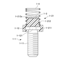
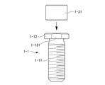
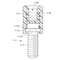
- FIG. 1 is a perspective view showing a first example of the first embodiment of the RFID-tagged wearing member of the present invention.
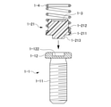
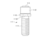
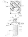
- FIG. 2 is a front sectional view showing an initial step of a manufacturing method of the first example of the first embodiment of the RFID-tagged wearing member of the present invention.
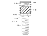
- FIG. 3 is a front sectional view showing a medium-term process of the manufacturing method of the first example of the first embodiment of the RFID-tagged wearing member of the present invention.
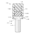
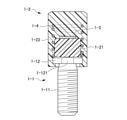
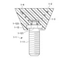
- FIG. 4 is a front sectional view showing the final step of the manufacturing method of the first example of the first embodiment of the RFID-tagged wearing member of the present invention.
- This RFID-tagged wearing member includes not only fastening members such as bolts and screws that are screwed into female screws and nuts, but also pins that are inserted into shaft holes.
- the RFID-tagged wearing member in the first embodiment is an example of a wearing member such as a bolt, the following mainly refers to "RFID.” Described as "tagged bolt”. As shown in FIG. 1, this RFID-tagged bolt includes a shaft-shaped portion 1-1, a head 1-2, an RFID (Radio Frequency Identification) tag 1-3, and a boost antenna 1-4. There is.
- the shaft-shaped portion 1-1 has an insert portion 1-11 and a base portion 1-12.
- the insert portion 1-11 and the base portion 1-12 are formed of a metal such as aluminum or stainless steel.
- the insert portion 1-11 has a shaft shape and is formed with a male screw. However, no male screw is formed in the vicinity of one end of the insert portion 1-11 (the portion continuous with the base portion 1-12).
- the base portion 1-12 is provided so as to project in the width direction at one end of the insert portion 1-11.
- the width direction is a direction orthogonal to the length direction of the insert portion 1-11.
- the width direction in the insert portion 1-11 on which the male screw is formed can be rephrased as the radial direction.
- the base portion 1-12 is formed in a disk shape. The center of the disk-shaped base portion 1-12 and the radial center of the insert portion 1-11 coincide with each other.
- a flat chamfered portion 1-121 is formed on a part of the outer peripheral surface of the base portion 1-12.
- the head 1-2 is formed by integrally integrating a pedestal portion 1-21 for mounting the RFID tag 1-3 on the top surface and a cap portion 1-22 for covering the main portion of the pedestal portion 1-21. ..
- the pedestal portion 1-21 is formed of resin on the surface side of the base portion 1-12 without the insert portion 1-11. As shown in FIG. 2, the pedestal portion 1-21 includes a diameter-expanded portion 1-211 and a protruding portion 1-212.
- the enlarged diameter portion 1-211 is formed in a ring shape surrounding the outer peripheral portion of the base portion 1-12.
- a bow-shaped locking portion (not shown) is formed on a part of the inner surface of the enlarged diameter portion 1-211 so as to engage with the chamfered portion 1-121 of the base portion 1-12.
- the protruding portion 1-212 projects from the center of the surface of the base portion 1-12 in a columnar or polygonal columnar direction in the direction opposite to the insert portion 1-11.
- a groove-shaped or recessed middle-low portion 1-212a is formed on the apical end surface of the protruding portion 1-212 to mount the RFID tag 1-3. As shown in FIGS. 1 and 3, the protrusion 1-212 is surrounded by a half (lower side in the drawing) of the base end side (lower side in the drawing) of the coil spring-shaped boost antenna 1-4.
- the cap portion 1-22 is a portion that covers the protruding portion 1-212 of the pedestal portion 1-21, and the RFID tag 1-3 and the boost antenna 1-4 are sealed with resin. Mold into a cylinder.
- the cap portion 1-22 is provided on the surface side of the base portion 1-12 with a slightly longer or substantially the same length as the insert portion 1-11 and having the same outer diameter as the enlarged diameter portion 1-211.
- the cap portion 1-22 is insert-molded by a mold (not shown). Although not shown, knurled eyes such as flatfish may be formed on the outer peripheral surface of the cap portion 1-22 in the length direction.
- RFID tags 1-3 are passive tags. That is, the RFID tags 1-3 do not have a built-in battery, receive radio waves from a reader / writer (not shown), and drive the RFID tags 1-3 as a power source.
- RFID tags 1-3 are ultra-compact (for example, 2.5 mm, 2.5 mm, 0.375 mm in length, width, and thickness) that combine an IC chip that records information and an antenna for wireless communication. It is a chip-shaped electronic component.
- the RFID tag 1-3 is mounted on the mid-low portion 1-212a formed on the top surface of the protruding portion 1-212 of the head 1-2, and is mounted on the cap portion 1-22 of the head 1-2 by a resin mold. It is sealed.
- the boost antenna 1-4 is formed in the shape of a cylindrical coil spring surrounding the protruding portion 1-212 of the pedestal portion 1-21, and boosts the radio waves transmitted and received to the RFID tag 1-3.
- the illustrated boost antenna 1-4 is drawn for easy viewing, and the actual boost antenna 1-4 may be formed with a pitch, wire diameter, and number of turns (not shown).
- the boost antenna 1-4 is formed of a conductor containing various metals and the like.
- the proximal end is fixed to the surface of the enlarged diameter portion 1-211, the proximal end side half surrounds the protruding portion 1-212, and the distal end side half is the protruding portion 1-212. Extend beyond the top.
- the protrusion 1-212 is preferably a length of 1/2 or more of the boost antenna 1-4.
- RFID tags 1-3 are arranged in the middle portion in the length direction of the boost antenna 1-4.
- the RFID tag 1-13 is arranged so as to be surrounded by the boost antenna 1-4 at a position away from the metal base portion 1-12.
- the boost antenna 1-4 is not electrically connected to the RFID tag 1-3.
- the boost antenna 1-4 is magnetically coupled to the antenna included in the RFID tag 1-3.
- the first manufacturing method of the RFID-tagged bolt of the first example of the first embodiment will be described with reference to FIGS. 2 to 4.
- the first manufacturing method of RFID-tagged bolts is divided into an initial process, an intermediate process, and a final process.
- the shaft-shaped portion 1-1 and the pedestal portion 1-21 are manufactured individually.
- the pedestal portion 1-21 is insert-molded with the molten resin. That is, the enlarged diameter portion 1-211 of the pedestal portion 1-21 surrounds the outer peripheral surface of the base portion 1-12, and the protruding portion 1-212 of the pedestal portion 1-21 protrudes from the surface of the base portion 1-12.
- the pedestal portion 1-21 is insert-molded.
- a mid-low portion 1-212a is formed on the top surface of the protruding portion 1-212.
- the RFID tag 1-3 is mounted on the top surface by fitting the RFID tag 1-3 into the middle and low portions 1-212a of the protruding portion 1-212 of the pedestal portion 1-21 that was initially molded. Then, the base end portion of the boost antenna 1-4 is installed in the enlarged diameter portion 1-211 of the pedestal portion 1-21.
- a component in which RFID tags 1-3 are placed inside boost antennas 1-4 is called a tag block.
- the protruding portion 1-212 of the pedestal portion 1-21 and the tag block (RFID tag 1-3 and boost antenna 1-4) are set in the cavity of the mold (not shown).
- the cavity of the mold is a space for insert molding the cap portion 1-22 of the head 1-2 with resin.
- the cavity is filled with molten resin with the mold closed.
- This molten resin is the same as the molten resin obtained by molding the pedestal portion 1-21.
- the bolt with RFID tag 1-3 formed by molding the cap portion 1-22 is completed. Since the pedestal portion 1-21 and the cap portion 1-22 are molded from the same molten resin, they are integrated to the extent that the boundary surface is not clear or difficult to understand. In FIG. 4, hatching in the opposite direction is provided so that the pedestal portion 1-21 and the cap portion 1-22 can be easily distinguished.
- this RFID-tagged bolt is taken out of the cavity by opening the mold.
- the cap portion 1-22 of the head 1-2 seals the tag block (RFID tag 1-3 and boost antenna 1-4). Since the cap portion 1-22 and the pedestal portion 1-21 of the head 1-2 are integrally molded by the same resin, the cap portion 1-22 does not slip in the circumferential direction or the length direction. Be integrated. Further, since the engaging portion and the chamfered portion 1-121 are linearly engaged with each other on the outer peripheral surface of the enlarged diameter portion 1-211 of the pedestal portion 1-21 and the base portion 1-12, respectively, the head portion is headed. The parts 1-2 and the base part 1-12 do not run idle.
- FIG. 5 is a front sectional view showing an initial step of a manufacturing method of a second example of the first embodiment of the RFID-tagged wearing member of the present invention.
- FIG. 6 is a front sectional view showing a medium-term process of the manufacturing method of the second example of the first embodiment of the RFID-tagged wearing member of the present invention.
- FIG. 7 is a front sectional view showing the final step of the manufacturing method of the second example of the first embodiment of the RFID-tagged wearing member of the present invention.
- the fitting recess 1- is centered on the surface of the base portion 1-12 of the shaft-shaped portion 1-1. It is assumed that 122 is formed and the fitting convex portion 1-213 is formed at the center of the base end surface of the enlarged diameter portion of the pedestal portion 1-21. In this RFID-tagged bolt, the fitting protrusion 1-213 is inserted into the fitting recess 1-122 to integrate the pedestal portion 1-21 and the base portion 1-12.
- the boost antennas 1-4 are formed in the shape of a coil spring as in the first example.
- the shaft-shaped portion 1-1 and the pedestal portion 1-21 are manufactured individually.
- the RFID tag 1-3 is further mounted on the middle and lower portions 1-212a of the protruding portion 1-212 of the pedestal portion 1-21.
- the boost antenna 1-4 is set in the enlarged diameter portion 1-211 of the pedestal portion 1-21.
- the RFID tag 1-3 is located in the middle of the boost antenna 1-4 in the length direction.
- the RFID tag 1-3 mounted on the protrusion 1-212 and the boost antenna 1-4 are combined to form a tag block.
- the fitting convex portion 1-213 of the pedestal portion 1-21 is fitted into the fitting concave portion 1-122 of the base portion 1-12.
- the boost antenna 4 may be exteriorized on the protruding portion 1-212 after the fitting convex portion 1-213 of the pedestal portion 1-21 is fitted into the fitting concave portion 1-122 of the base portion 12.
- the tag block RFID tag and boost antenna 4
- the pedestal portion 1-21 and the base portion 1-12 are set in the mold. Then, with the mold closed, the same molten resin as the pedestal is injected into the cavity. When the molten resin solidifies, the RFID-tagged bolt forming the cap portion 1-22 is completed. Since the pedestal portion 1-21 and the cap portion 1-22 are molded from the same molten resin, they are integrated to the extent that the boundary surface is not clear or difficult to understand.
- this RFID-tagged bolt is taken out of the cavity by opening the mold. Similar to the RFID-tagged bolt manufactured by the manufacturing method of the first example, the RFID-tagged bolt also has a head 1-2 in which the pedestal portion 1-21 and the cap portion 1-22 are integrated. There is. Therefore, when the head 1-2 is rotated in the circumferential direction, the RFID-tagged bolt is integrally rotated without the shaft-shaped portion 1-1 spinning idle.
- FIG. 8 is a front sectional view showing an initial step of a manufacturing method of a third example of the first embodiment of the RFID-tagged wearing member of the present invention.
- FIG. 9 is a front sectional view showing a medium-term process of the manufacturing method of the third example of the first embodiment of the RFID-tagged wearing member of the present invention.
- FIG. 10 is a front sectional view showing a medium-term process of a manufacturing method of a third example of the first embodiment of the RFID-tagged wearing member of the present invention.
- FIG. 11 is a front sectional view showing the final step of the manufacturing method of the third example of the first embodiment of the wearing member with RFID tag of the present invention.
- the surface of the base portion 1-12 of the shaft-shaped portion 1-1 is formed flat, and the pedestal portion 1-21 is formed. Is formed in a rectangular parallelepiped shape.
- the pedestal portion 1-21 may be formed in a cubic shape. In any case, the middle and low portions are not formed on the top surface of the pedestal portion 1-21.
- the width of the pedestal portion 1-21 is smaller than the outer shape of the base portion 12, in other words, the surface of the base portion 1-12 protrudes from the pedestal portion 1-21.
- the boost antennas 1-4 are formed in the shape of a coil spring as in the first example.
- the pedestal portion 1-21 is adhered to the base portion 1-12 of the shaft-shaped portion 1-1. It is fixed by an agent or the like.
- RFID tags 1-3 are fixed to the top surface of the pedestal portion 1-21 with an adhesive or the like.
- a mid-low portion is formed on the surface of the pedestal portion 1-21, and the RFID tag is formed on the mid-low portion. May be embedded.
- the boost antenna 1-4 further surrounds the pedestal portion 1-21 so that the base portion 1- It is set on 12.
- the base end of the boost antenna 1-4 is fixed to the pedestal portion 1-21, the intermediate portion surrounds the RFID tag 1-3, and the tip end side extends longer than the top surface of the pedestal portion 1-21.
- the pedestal portion 1-21 and the base portion 1-12 on which the RFID tag 1-3 is mounted are formed. Is molded with resin, and the cap portion 1-22 is molded. That is, in the final step, the head portion 1-2 is formed by molding the pedestal portion 1-21 with the cap portion 1-22. When the head 1-2 is turned in the circumferential direction, the RFID-tagged bolt is integrally turned without the shaft-shaped portion 1-1 spinning idle.
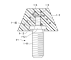
- FIG. 12 is a front sectional view showing an initial step of the manufacturing method of the fourth example of the first embodiment of the RFID-tagged wearing member of the present invention.
- FIG. 13 is a front sectional view showing a medium-term process of the manufacturing method of the fourth example of the first embodiment of the RFID-tagged wearing member of the present invention.
- FIG. 14 is a front sectional view showing the final step of the manufacturing method of the fourth example of the first embodiment of the wearing member with RFID tag of the present invention.
- the protrusion 1-123 is formed in the center of the base portion 1-12 on the surface side in the initial step. Further, in the initial step, the boost antenna 1-4 is set on the base portion 1-12 so that the base end side half portion of the boost antenna 1-4 surrounds the protrusion portion 1-132 of the base portion 1-12.
- the base portion 1-12 of the shaft-shaped portion 1-1 is set in the cavity of the mold, and the pedestal portion is formed.
- the original shape 1-20 of the head having 1-21 is molded by molten resin.
- a vertical hole portion 1-201 is formed at the top of the original shape 1-20 of the head. Therefore, the mold used in the intermediate step of the manufacturing method of the fourth example of the first embodiment includes a first core for forming the vertical hole portion 1-201. However, the vertical hole portion 1-201 may be formed by a drill or the like.
- the boost antenna 1-4 in which the original shape of the head 1-20 is set on the pedestal portion 1-21 is sealed with the molten resin.
- the RFID tag 1-3 is mounted behind the vertical hole 201 of the prototype 20 of the head. Subsequently, using the second core of the mold, the molten resin is injected into the vertical hole of the prototype 1-20 of the head on which the RFID tag 1-3 is mounted. Therefore, the mold used in the final step of the third manufacturing method includes a second core for forming the vertical hole portion 1-201. When this molten resin 1-202 solidifies, it becomes one with the original shape 1-20 of the head, and the final head 1-2 is completed.
- a resin stopper to be fitted into the vertical hole portion 1-21 may be separately manufactured without injecting the molten resin into the vertical hole portion 1-21 using the second core.
- the resin stopper is fixed with an adhesive so as to be fitted in the vertical hole of the original shape 1-20 of the head on which the RFID tag 1-3 is mounted. Since the stopper is not turned or twisted, it is fixed to the original shape of the head 1-20 so as not to come off from the vertical hole portion 1-201.
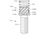
- FIG. 15 is a front sectional view showing a fifth example of the first embodiment of the RFID-tagged wearing member of the present invention.
- the fifth example of the first embodiment of the RFID-tagged wearing member is the same as the first to fourth examples of the first embodiment, the axial portion 1-1 and the head 1-2. , RFID tags 1-3, and boost antennas 1-4.
- the boost antenna 1-4 of the fifth example of the first embodiment is formed in the shape of a conical coil spring.
- the boost antenna 1-4 of the fifth example of the first embodiment the diameter of the base end side installed on the base portion 1-12 is reduced and the diameter of the tip end side is expanded. Therefore, the head 1-2 of the first example of the first embodiment has a conical shape in which the diameter of the base portion 1-12 side is reduced and the diameter of the tip portion is expanded.
- a protrusion 1-123 protrudes from the surface of the base portion 1-12.
- RFID tags 1-3 are mounted on the top surface of the protrusions 1-123.
- the cap portion 1-22 molds the base portion 1-12 and the protrusion portion 1-123 of the shaft-shaped portion 1-1 and the tag block (RFID tag 1-3 and boost antenna 1-4) with resin. Since the boost antenna 1-4 is formed in the shape of a cylindrical coil spring with the tip side expanded, the cap portion 1-22 has a truncated cone shape with the tip side expanded along the outer circumference of the boost antenna 1-4. It is formed.
- the cap portion 1-22 is insert-molded by a mold. On the outer peripheral surface of the cap portion 1-22, knurled eyes such as flatfish may be formed in the length direction.
- the boost antenna 1-4 of the fifth example of the first embodiment is arranged so that the reduced diameter side surrounds the RFID tag 1-3. That is, since the diameter of the base portion 12 side of the boost antenna 1-4 is reduced, the protrusion 1-123 is formed low.
- the shape of the boost antenna 1-4 makes adjustments according to the desired sensitivity characteristics.
- FIG. 16 is a front sectional view showing a sixth example of the first embodiment of the RFID-tagged wearing member of the present invention.
- the diameter of the base end side installed on the base portion 1-12 is expanded and the diameter of the tip end side is reduced.
- RFID tags 1-3 are mounted on the top surface of the protrusion 1-123 protruding from the base portion 1-12.
- RFID tags 1-3 are arranged on the reduced diameter end side of the boost antenna 1-4.
- the tip side of the boost antenna 1-4 since the tip side of the boost antenna 1-4 has a reduced diameter, the protrusion 1-123 is formed high.
- the shape of the boost antennas 1-4 is adjusted according to the desired sensitivity characteristics.
- the tip side of the cap portion 1-22 is shrunk by the resin that seals the base portion 1-12 of the shaft-shaped portion 1-1, the protrusion 1-123, and the tag block (RFID tag 1-3 and boost antenna 1-4). Mold into a truncated cone with a diameter. Since the boost antenna 1-4 is formed in the shape of a conical coil spring, the cap portion 1-22 is formed in a conical shape along the outer circumference of the boost antenna 1-4. The cap portion 1-22 is insert-molded by a mold. On the outer peripheral surface of the cap portion 1-22, knurled eyes like flatfish are formed in the length direction.
- the RFID tag 1-3 is arranged on the base end side of the cylindrical coil spring-shaped boost antenna 1-4 shown in the first example. Therefore, the protrusion 1-123 of the base portion 1-12 on which the RFID tag 1-3 is mounted is formed lower than the protrusion 1-123 shown in FIGS. 1 to 4. Alternatively, the vertical hole portions 1-201 as shown in FIGS. 13 and 14 are deeply formed.
- the RFID tag 1-3 is arranged on the tip side of the cylindrical coil spring-shaped boost antenna 1-4 shown in the first example. Therefore, the protrusion 1-123 of the base portion 1-12 on which the RFID tag 1-3 is mounted is formed higher than the protrusion 1-123 shown in FIGS. 1 to 4. Since the RFID tag 1-3 mounted on such a protrusion 1-123 is separated from the base portion 1-12 of the shaft-shaped portion 1-1, it is affected by the base portion 1-12 of the shaft-shaped portion 1-1. It becomes difficult to receive and the performance improves.
- the data transmitted from the reader / writer is the RFID tag 1-3.
- RFID-tagged bolts Used in various fields such as written in.
- RFID-tagged bolts are used in mold management systems.
- the mold managed in the mold management system (hereinafter referred to as "managed mold") may be stored for, for example, 15 years or more after the production of the product is finished.
- this RFID-tagged bolt is equipped with a boost antenna 1-4, so that even if the RFID tag 1-3 is a passive type that transmits and receives weak radio waves, the radio waves are boosted and the directivity in the radial direction is improved. It can be improved and radio waves can be reliably transmitted and received with the reader / writer.
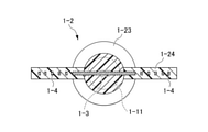
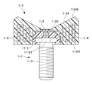
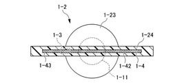
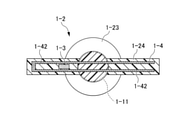
- FIG. 17A is a partial cross-sectional plan view showing a first example of the first and second embodiments of the RFID-tagged wearing member of the present invention.
- FIG. 17B is a front sectional view showing a first example of the first and second embodiments of the RFID-tagged wearing member of the present invention.
- the RFID-tagged wearing member of the first example of the first embodiment of the first and second embodiments has a shaft-shaped portion 1-1 and a head 1 as in the first embodiment. -2, RFID tag 1-3, and boost antenna 1-4.
- the RFID-tagged dressing member of the first embodiment of the first and second embodiments includes a head 1-2 having plate-shaped ribs 1-24 protruding in the radial direction of the insert portion 1-11. ..
- the head 1-2 is provided with a deformed cylindrical central portion 1-23 surrounding the base portion 1-12 and a pair of plate-shaped ribs 1-24.
- the central portion 1-23 has a shape in which a columnar portion and a truncated cone-shaped portion are integrally molded in the axial direction.
- Each pair of ribs 1-24 protrudes radially from the central portion 1-23 like a thumbscrew.
- Each rib 1-24 has a bottom portion 1-241 orthogonal to the axial direction of the insert portion 1-11 and an inclined portion 1 protruding from the central portion 23 diagonally with respect to the axial direction of the insert portion 1-11. It has -242.
- the boost antenna 1-4 is patterned in the head 1-2 like a mianda-shaped conductor pattern according to the shape of the thumbscrew-shaped head 1-2.
- This meander-shaped conductor pattern is formed so that the width on the base end side of the rib 1-24 is narrow and the width on the tip end side is gradually widened when the length direction of the insert portion 1-11 is the width direction. ing.
- the base end of each of the meander-like conductor patterns in each rib 1-24 is in close proximity to the RFID tag. That is, the boost antennas 1-4 are not electrically connected to the RFID tags 1-3.
- the boost antennas 1-4 of the myunder-shaped conductor pattern have both magnetic field coupling type and capacitive coupling type functions.
- the boost antennas 1-4 shown in FIGS. 17A and 17B have a myunder-shaped conductor pattern that gradually widens on the tip side.
- the boost antennas 1-4 may have a meander-like conductor pattern having the same width over the entire length.
- the ribs 1-24 are formed so that the bottom side and the top side portion are parallel to each other.
- FIG. 18A is a cross-sectional front view showing the first example of the first and second embodiments of the RFID-tagged wearing member of the present invention, showing the initial process of the first manufacturing method.
- FIG. 18B is a cross-sectional front view showing a first example of the first and second embodiments of the RFID-tagged wearing member of the present invention, showing a medium-term process of the first manufacturing method.
- FIG. 18C is a front sectional view showing the final step of the first manufacturing method according to the first example of the first and second embodiments of the RFID-tagged wearing member of the present invention.
- the head 1-2 of this RFID-tagged bolt Since the head 1-2 of this RFID-tagged bolt has a meander-shaped conductive pattern, it is molded by a mold that is in-molded in a lying position. As shown in FIG. 18A, in the first manufacturing method of the RFID-tagged bolt of the first embodiment of the first embodiment, in-mold semi-molding is performed to half one side in the thickness direction of the head 1-2. Head 1-200 is formed. The outer circumference of this half head 1-200 is bordered, and a flat recess 1-210 is formed inside the border.
- the boost antenna 1-4 of the conductor pattern and the RFID tag 1-3 are set in the recess 1-210 formed in the head 1-2 of one half. Will be done. Since the outer circumference of the lower half of the head 1-2 is bordered, the boost antenna 1-4 does not shift from the inside of the recess 1-210.
- the cavity is replaced with a different mold, the molten resin is molded in the recess 1-210 in which the boost antenna 1-4 and the RFID tag 1-3 are set, and the other half is molded.
- the head 1-2 is molded.
- the RFID-tagged bolt having such a head 1-2 can be tightened or loosened by turning the ribs 1-24, so that the usability is improved in addition to the sensitivity.
- FIG. 19A is a first example of the first and second embodiments of the RFID-tagged wearing member of the present invention, and is a front view showing an initial step of the second manufacturing method.
- FIG. 19B is a first example of the first and second embodiments of the RFID-tagged wearing member of the present invention, and is a front view showing a medium-term process of the manufacturing method of the first and second.
- FIG. 19C is a first example of the first and second embodiments of the RFID-tagged wearing member of the present invention, and is a front sectional view showing the final step of the second manufacturing method.
- the boost antenna 1-4 and the RFID tag 1-3 having a meander-shaped conductor pattern are sealed with a base material packing material such as a seal. Use the inlay attached to (web).
- the head 1 having the positioning boss 1-25 for positioning the inlay.
- the head 1-200 on one side half in the thickness direction of -200 is in-molded and semi-molded.
- the web is set on the in-molded semi-molded half of the head 1-2.
- the web is set in place by the positioning boss 1-25.
- the cavity of the mold is replaced, the other half of the head 1-2 is molded, and the head 1-2 having a predetermined shape is formed.
- FIG. 20A is a second example of the first and second embodiments of the RFID-tagged wearing member of the present invention, and is a sectional plan view taken along line AA of FIG. 20C showing the final step.
- FIG. 20B is a second example of the first and second embodiments of the RFID-tagged wearing member of the present invention, and is a sectional view taken along line BB of FIG. 20C showing the final process.
- FIG. 20C is a second example of the first and second embodiments of the RFID-tagged wearing member of the present invention, and is a second cross-sectional front view showing the final process.
- the RFID-tagged wearing member of the second example of the first and second embodiments has the axial portion 1-1 and the head 1 as in the first embodiment. -2, RFID tag 1-3, and boost antenna 1-4.
- the RFID-tagged wearing member of the second embodiment of the first and second embodiments includes a rectangular plate-shaped head 1-2 that protrudes in the radial direction of the insert portion 1-11.
- the head 1-2 of the second example of the first and second embodiments includes a deformed cylindrical central portion 1-23 surrounding the base portion 1-12 and a rectangular plate-shaped rib 1-24. There is.
- the central portion 1-23 has a shape in which a columnar portion and a truncated cone-shaped portion are integrally molded in the axial direction. The lower and upper sides of ribs 1-24 are formed in parallel.
- the boost antenna 1-4 of the second example of the first and second embodiments is U-shaped in front view, and has two parallel stick-shaped portions 1-42 and one end of both stick-shaped portions 1-42. It has a folded-back portion 1-43 connecting the sides.
- the central portion 1-23 of the stick-shaped portion 1-42 on the axial portion 1-1 side is fixed to the truncated cone-shaped portion of the head 1-2.
- Boost antennas 1-4 with a U-shaped conductor pattern have both magnetic field coupling type and capacitive coupling type functions.
- the RFID tag 1-3 is sandwiched between the two stick-shaped portions 1-42 so as to be located in the rib 1-24.
- the RFID tags 1-3 shown in FIGS. 20A to 20C are arranged at positions close to the folded-back portion 1-43 of the boost antenna 1-4, they may be arranged at the tip end side.
- RFID tags 1-3 are placed in one of the ribs 1-24, not in the center of the head 1-2.
- the RFID tags 1-3 may be placed in the head 1-2 instead of in the ribs 1-24. That is, the location of the RFID tags 1-3 is not limited.
- the RFID-tagged dressing member of the second example of the first and second embodiments has a zigzag (ninety-nine) fold in which RFID tags 1-3 have a plurality of stick-shaped portions 1-42 arranged in parallel, in other words. Then, it may be a horizontal meander-like pattern. In this case, the RFID tags 1-3 are sandwiched between any of the adjacent stick-shaped portions 1-42. Further, the ribs 1-24 for molding the zigzag boost antenna 1-4 are formed higher than the ribs 1-24 for molding the U-shaped boost antenna 1-4.
- the second example of the RFID-tagged dressing member according to the first and second embodiments is manufactured in the same manner as the first example of the RFID-tagged dressing member according to the first and second embodiments.
- FIG. 21A is a third example of the first and second embodiments of the RFID-tagged wearing member of the present invention, and is a partial cross-sectional plan view showing the final step.
- FIG. 21B is a third example of the first and second embodiments of the RFID-tagged wearing member of the present invention, and is a front sectional view showing the final process.
- the RFID-tagged wearing member of the third example of the first and second embodiments has the same axial portion 1-1 and the head 1-2 as in the first embodiment. , RFID tags 1-3 and boost antennas 1-4.
- the RFID-tagged wearing member of the second embodiment of the first and second embodiments includes a rectangular plate-shaped head 1-2 that protrudes in the radial direction of the insert portion 1-11.
- the head 1-2 of the third example of the first and second embodiments includes a deformed cylindrical central portion 1-23 surrounding the base portion 1-12 and a rectangular plate-shaped rib 1-24. There is.
- the central portion 1-23 has a shape in which a columnar portion and a truncated cone-shaped portion are integrally molded in the axial direction.
- the lower and upper sides of ribs 1-24 are formed in parallel.
- the ribs 1-24 of the third example are formed thicker than the ribs 1-24 of the second example.
- the boost antenna 1-4 of the third example of the first and second embodiments is a member folded in half so that one side of the stick-shaped portion 1-42 faces each other.
- the stick-shaped portion 1-42 has a rectangular shape having a long side and a short side, and a crease is provided on the short side and is arranged in one end of the rib 1-24.
- Each tip of the facing stick-shaped portions 1-42 of the boost antenna 1-4 is arranged within the other end of the rib 1-24.
- the boost antenna 1-4 of the conductor pattern of the bi-fold member has both magnetic field coupling type and capacitive coupling type functions. If the folds of the boost antennas 1-4 folded in half are provided on the long side, the communication distance is significantly reduced.
- the RFID tag 1-3 is sandwiched between the stick-shaped portions 1-42 of the boost antenna 1-4 of this bi-fold member.
- the RFID tags 1-3 shown in FIG. 21 are arranged near the center 1-23 of the boost antenna 1-4.
- the RFID tags 1-3 may be arranged near the folded-back portion 1-43. In any case, the RFID tag 1-3 is placed on the ribs 1-24, not on the center of the head 1-2.
- the third example of the first and second embodiments of the RFID-tagged dressing member is manufactured in the same manner as the first example of the first and second embodiments of the RFID-tagged dressing member.
- the RFID tags 1-3 of the first to third embodiments of the first and second embodiments are expanded as the distance from the RFID tags 1-3 is increased by making the boost antenna 1-4 stick-shaped. As the radiation surface expands and narrows, the communication distance is concentrated and extended. Further, by changing the shape of the boost antenna 1-4, the feeling of size of the head 1-2 can be changed.
- the embodiment of the RFID-tagged bolt according to the present invention is not limited to the above contents, and includes deformation, improvement, and the like to the extent that the object of the present invention can be achieved.
- the insert portion 1-11 is assumed to have a shaft shape in which a male screw is formed.
- the insert portion 1-11 may be a pin on which a male screw is not formed, and the pin is not limited to a columnar shape and may be a prismatic shape.
- the base portion 1-12 is formed in a disk shape.
- the base portion 1-12 may have a polygonal shape.
- the outer peripheral surface of the base portion 1-12 is formed with the chamfered portion 1-121, and the head 1-2 has a locking portion to be joined to the chamfered portion 1-121. ..
- the outer peripheral surface of the base portion 1-12 may not form the chamfered portion 1-121 but may have knurled eyes, and the inner surface of the head 1-2 may enter the knurled eyes.
- the chamfered portion 1-121 is not formed on the base portion 1-12, and the head portion 1-2 has a locking portion. You may not do it.
- the insert portion 1-11 and the base portion 1-12 are made of metal.
- either one or both of the insert portion 1-11 and the base portion 1-12 may be formed of resin.
- RFID-tagged bolts can also be used in the logistics field, railway field, food and beverage industry, and the like.
- logistics field it is screwed into the body of trucks and containers to manage the distribution of products.
- railroad field manage bolt loosening. This bolt may be used in a larger size than when screwed into a controlled mold.
- a bolt with an RFID tag may be attached to a plate to control the elapsed time of the sushi placed on the plate, or the sushi may be delivered directly to the individually ordered audience seats.
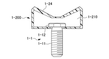
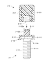
- FIG. 22 is a front sectional view showing the head of the RFID-tagged wearing member of the present invention and the first example of the first embodiment of the RFID tag mount unit 2-1.
- FIG. 23 is a front sectional view showing a first example of the second embodiment of the RFID-tagged wearing member of the present invention.
- This RFID-tagged wearing member includes not only fastening members such as bolts and screws that are screwed into female screws and nuts, but also pins that are inserted into shaft holes.
- the RFID-tagged wearing member in the second embodiment is an example of a wearing member such as a bolt.
- this RFID-tagged bolt includes an RFID (Radio Frequency Identification) tag mount unit 2-1 and a head 2-2.
- the RFID tag mount unit 2-1 includes a shaft-shaped portion 2-11, a pedestal portion 2-12, and an RFID tag 2-13.
- the shaft-shaped portion 2-11 has an insert portion 2-111 and a base portion 2-112.
- the insert portion 2-111 and the base portion 2-112 are formed of a metal such as aluminum or stainless steel.
- the insert portion 2-111 has a shaft shape and is formed with a male screw. However, no male screw is formed in the vicinity of one end of the insert portion 2-111 (the portion continuous with the base portion 2-112).
- the base portion 2-112 is provided at one end of the insert portion 2-111 so as to project in the cross-sectional direction.
- the cross-sectional direction is a direction orthogonal to the length direction of the insert portion 2-111.
- the cross-sectional direction of the insert portion 2-111 on which the male screw is formed can be rephrased as the radial direction or the width direction.
- the base portion 2-112 is formed in a disk shape.
- the center of the disk-shaped base portion 2-112 and the center of the insert portion 2-111 in the cross-sectional direction coincide with each other.
- a flat chamfered portion 2-112a is formed on a part of the outer peripheral surface of the base portion 2-112.
- the pedestal portion 2-12 is insert-molded with resin on the surface side (upper side in the drawing) of the base portion 2-112 without the insert portion 111. As shown in FIG. 22, the pedestal portion 2-12 includes an expansion portion 2-121 and a protrusion 2-122.
- the expansion portion 2-121 is formed in a round tray shape having an annular portion surrounding the outer peripheral portion of the base portion 2-112.
- the expansion portion 2-121 is insert-molded into the base portion 2-112 and integrated so as not to be separated from the base portion 2-112.
- a bow-shaped locking portion (not shown) is formed on a part of the inner surface of the expansion portion 2-121 so as to engage with the chamfered portion 2-112a of the base portion 2-112.
- the protruding portion 2-122 protrudes from the center of the surface of the base portion 2-112 in a polygonal columnar shape or a columnar shape in the direction opposite to the insert portion 2-111.
- the protrusion 2-122 is formed on the head 2-2 by forming the protrusion 2-122 into a polygonal columnar shape, or by providing an arch-shaped locking portion on the columnar protrusion 2-122. On the other hand, it can be prevented from slipping.
- An enclosed portion 2-122a for embedding the RFID tag 2-13 is formed at the top end of the protruding portion 2-122.
- the RFID tag 2-13 is embedded in the apex of the insert-molded protrusion 2-122 to be protected.
- the RFID tag 2-13 may be fixed to the apical end surface of the projecting portion 2-122 with an adhesive or the like without being embedded in the sealing portion 2-122a so that the RFID tag 2-13 is exposed.
- a recessed middle-low portion may be formed on the apex end surface of the protruding portion 2-122, and the RFID tag 2-13 may be embedded in the middle-low portion.
- the RFID tag 2-13 embedded in the middle and low portions may be fixed by an adhesive or the like.
- the RFID tag 2-13 is a passive tag. That is, the RFID tag 2-13 does not have a built-in battery, receives radio waves from a reader / writer (not shown), and drives the radio waves as a power source.
- RFID tag 2-13 is an ultra-compact (for example, length, width, thickness 2.5 mm, 2.5 mm, 0.375 mm) that combines an IC chip that records information and an antenna for wireless communication. It is a chip-shaped electronic component.
- the head portion 2-2 of the first example of the second embodiment has a cap 2-21 that covers the protruding portion 2-122 of the pedestal portion 2-12 and a boost antenna built in the cap 2-21. It is equipped with 2-221.
- the head 2-2 is formed of a resin separately from the pedestal portion 2-12 and is removable.
- the head portion 2-2 projects toward the surface side of the base portion 2-112 and is provided with the same outer diameter as the expansion portion 2-121 of the pedestal portion 2-12.
- the cap 2-21 is insert-molded by a mold.
- the cap 2-21 is formed in the shape of a one-sided occlusion cylinder having a thick occlusion portion on one end side (upper side in the drawing).
- the cap 2-21 having a one-sided obstruction cylinder is formed into a one-end obstruction cylinder, one end obstruction square cylinder, or the like (the same applies to the following embodiments).
- knurled eyes such as flatfish may be formed on the outer peripheral surface of the cap 2-21 in the length direction.
- a recessed fitting portion 2-211 into which the protruding portion 2-122 of the pedestal portion 2-12 is inserted, is formed in the center of the base end side (lower side in the drawing) of the cap 2-21. ..
- the recessed portion 2-211 is formed in a shape into which the protruding portion 2-122 is inserted. That is, if the protruding portion 2-122 has a square tubular shape, the recessed fitting portion 2-211 is formed in a square hole shape. If the protruding portion 2-122 is cylindrical, the recessed fitting portion 2-211 is formed in a cylindrical shape.
- the cap 2-21 incorporates a coil spring-shaped boost antenna 2-221. The base end side of the boost antenna 2-221 is arranged between the recessed portion 2-211 and the outer surface.
- the boost antenna 2-221 boosts the radio waves transmitted to and received from the RFID tag 2-13.
- the boost antenna 2-221 is formed into a cylindrical coil spring shape by a conductor wire containing metal or the like. As shown in FIG. 23, the length of the protruding portion 2-122 is preferably 1 ⁇ 2 or more with respect to the length of the boost antenna 2-221.
- the base end of the boost antenna 2-22 is fixed to the surface of the extension 2-121, the base end side half surrounds the protrusion 2-122, and the tip end side half extends beyond the top surface of the protrusion 2-122. Put out.
- RFID tag 2-13 is arranged in the middle portion in the length direction of the boost antenna 2-221.
- the boost antenna 2-221 is not electrically connected to the RFID tag 2-13.
- the boost antenna 2-221 is magnetically coupled to the antenna included in the RFID tag 2-13.
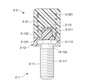
- FIG. 24 is a front sectional view showing a second example of the head of the RFID-tagged dressing member of the present invention and the second embodiment of the RFID tag mount unit.
- FIG. 25 is a front sectional view showing a second example of the second embodiment of the RFID-tagged wearing member of the present invention.
- the RFID tag mount unit 2-1 of the second example of the second embodiment has the same axial portion 2-11, the pedestal portion 2-12, and the RFID as the first example of the second embodiment. It has tags 2-13 and.
- the cap 2-21 of the second example of the second embodiment has a one-sided closed cylinder having an outer diameter larger than that of the expansion portion 2-121 of the pedestal portion 2-12. That is, the base end portion of the cap 2-21 fits the expansion portion 2-121 externally. Therefore, the cap 2-21 is formed with a stepped hole portion 2-212 into which the expansion portion 2-121 is fitted on the base end side of the recessed fitting portion 2-211 into which the protruding portion 2-122 is inserted.
- the RFID tag 2-13 is arranged on the tip end side or the base end side of the boost antenna 2-221 by making the protrusion of the pedestal portion 2-12 higher or lower than in the first and second examples.
- the type is stocked.
- the boost antenna 2-221 may have a conical coil spring shape in which the diameter of the distal end side or the proximal end side is reduced and the diameter of the proximal end side or the distal end side is expanded, instead of the cylindrical shape.
- the cap 2-21 has a conical shape to match the shape of the boost antenna 2-221.
- the head 2-2 with the boost antenna 2-221 according to the second embodiment is appropriately selected from various types according to the sensitivity of the RFID tag 2-13, and the pedestal portion 2- It is attached to and detached from 12.
- the pedestal portion 2-12 until it is attached to the head 2-2 is exposed.
- the RFID tag 2-13 embedded in the apex of the protrusion 2-122 of the pedestal 2-12 is less likely to be damaged.
- the protruding portion 2-122 of the pedestal portion 2-12 is inserted into the recessed fitting portion 2-211.
- the expansion portion 2-121 of the pedestal portion 2-12 is fitted into the step hole portion 2-212.
- the RFID-tagged bolt of the second embodiment is used in various fields such that the data transmitted from the reader / writer is written to the RFID tag 2-13.
- RFID-tagged bolts are used in mold management systems.
- the mold managed in the mold management system (hereinafter referred to as "managed mold") may be stored for, for example, 15 years or more after the production of the product is finished.
- this RFID-tagged bolt is provided with a boost antenna 2-221 so that even if the RFID tag 2-13 is a passive type that transmits and receives weak radio waves, the radio waves are boosted and the directivity in the cross-sectional direction is directional. It is possible to reliably send and receive radio waves to and from the reader / writer.
- the head 2-2 of this RFID-tagged bolt is replaceable, the most suitable type of head 2-2 is selected according to the mounting situation. For example, when the head portion 2-2 is to be firmly attached to the pedestal portion 2-12, not only the protruding portion 2-122 is inserted into the recessed fitting portion 2-211, but also the base portion 2-112 is a stepped hole portion. The head 2-2 of the second example fitted in 2-212 is selected. Further, the head 2-2 of the first example is attached to the RFID-tagged bolt attached in a narrow space, and the head 2-2 of the second example is attached to the RFID-tagged bolt attached in a wide space. ..
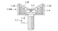
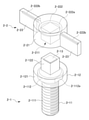
- FIG. 26 is an exploded perspective view showing the head of the RFID-tagged wearing member of the present invention and the second-second embodiment of the RFID tag mount unit.
- FIG. 27 is a front sectional view showing the second and second embodiments of the RFID-tagged wearing member of the present invention.
- the RFID-tagged bolt of the second embodiment includes an RFID tag mount unit 2-1 and a head 2-2.
- the RFID tag mount unit 2-1 includes the same axial portion 2-11 as in the embodiment of the second embodiment, a pedestal portion 2-12, and an RFID tag 2-13.
- the head 2-2 is provided with a cap 2-21 that covers the main part of the pedestal portion 2-12 on which the RFID tag 2-13 is mounted on the top surface, and a boost antenna 2-222.
- the head 2-2 is formed separately from the pedestal portion 2-12 and is removable.
- the head 2-2 of the RFID-tagged wearing member according to the second embodiment is different from the second embodiment in that the cap 2-21 has a cylindrical shape at one end and the side surface of the cap 2-21. It is provided with a pair of plate-shaped ribs 2-23 extending in opposite directions.
- the ribs 2-23 have a wide width substantially the same as the axial length (height in the drawing) of the cap 2-21, and project in the cross-sectional direction (diametrical direction in the drawing).
- a finger is placed on the ribs 2-23 of the cap 2-21. Since the ribs 2-23 are formed in a wide plate shape, they are less likely to break than when they are formed in a shaft shape, and the head 2-2 can be easily turned without biting into the fingers. However, the ribs 2-23 may be formed in a shaft shape.
- the cap 2-21 is formed with a square hole-shaped concave fitting portion 2-211 into which the prismatic protruding portion 2-122 of the pedestal portion 2-12 is inserted.
- the RFID tag 2-13 is embedded in the apex of the protrusion 2-122.
- the RFID tag 2-13 is sandwiched between the inner inner surface of the concave fitting portion 2-21 of the cap 2-21 and the apical end surface of the protruding portion 2-122.
- the protruding portion 2-122 may be cylindrical, and the concave fitting portion 2-211 may be cylindrical. In this case, knurled stitches are formed on the surface where the protruding portion 2-122 and the concave fitting portion 2-211 overlap, or a chamfered portion and a locking portion to be engaged with each other are formed.
- the boost antenna 2-222 is provided with an element that integrates the loop portion 2-222a and the straight portion 2-222b.
- the loop portion 2-222a is embedded in the cap 2-21 so as to surround the tip end side of the recessed fitting portion 2-211.
- the illustrated loop portion 2-222a is formed in an annular shape having only one and a half rounds.
- the head (not shown) has a loop portion 2-222a formed in an annular shape having two and a half turns or more built in the cap 2-21.
- each end of the diameter of the loop portion 2-222a and the straight portion 2-222b are continuous.
- Two straight portions 2-222b are formed in a shaft shape and are incorporated in each rib 2-23.
- the straight portion 2-222b is arranged on one end edge side (upper end side in the drawing) of the ribs 2-23.
- the two straight portions 2-222b and the RFID tag 2-13 are arranged in a straight line. Therefore, the loop portion 2-222a connected to the straight portion 2-222b has the same height position as the connection position with the straight portion 2-222b, and has an overall inclined ring shape.
- the head 2-2 of the second embodiment is stocked with various types of boost antennas 2-22 built-in.
- the boost antenna 2-222 is formed in various forms such that not only the number of turns of the loop portion 2-222a is different but also the length of the straight portion 2-222b is different.
- the head 2-2 is appropriately selected according to the radio waves transmitted to and received from the RFID tag 2-13, and is attached to the pedestal portion 2-12. That is, the protruding portion 2-122 of the pedestal portion 2-12 is inserted into the recessed fitting portion 2-21 of the cap 21, so that the pedestal portion 2-12 and the cap 2-21 are integrated into the head 2-. It becomes 2.
- the RFID tag 2-13 mounted on the protruding portion 2-122 of the pedestal portion 2-12 is surrounded by the loop portion 2-222a of the boost antenna 2-222. It will be in a state of being.
- the RFID-tagged bolt of the second embodiment is provided with a boost antenna 2-222 in which a loop portion 2-222a and a straight portion 2-222b are integrated, so that the RFID tag 2-13 emits weak radio waves. Even if it is a passive type that transmits and receives radio waves, the radio waves are boosted, the directivity in the cross-sectional direction is improved, and radio waves can be reliably transmitted and received with the reader / writer.
- FIGS. 28 and 29 for the first example of the second and third embodiments of the RFID-tagged wearing member of the present invention
- FIGS. 30 and 31 for the second example of the second and third embodiments. It will be explained with reference to it.
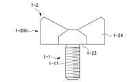
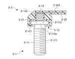
- FIG. 28 is a front sectional view showing the head of the RFID-tagged wearing member of the present invention and the first example of the second and third embodiments of the RFID tag mount unit.
- FIG. 29 is a front sectional view showing a first example of the second and third embodiments of the RFID-tagged wearing member of the present invention.
- FIG. 30 is a cross-sectional front view showing the head of the RFID-tagged wearing member of the present invention and the second example of the second and third embodiments of the RFID tag mount unit.
- FIG. 31 is a front sectional view showing a second example of the second and third embodiments of the RFID-tagged wearing member of the present invention.
- the RFID-tagged bolts of the first and second embodiments of the second and third embodiments include an RFID tag mount unit 2-1 and a head 2-2. ing.
- the RFID tag mount unit 2-1 has the same axial portion 2-11 as in the embodiment of 2-1 and the same pedestal portion 2-12 and RFID tag 2-13 as in the embodiment of 2-1. I have.
- the pedestal portion 2-12 includes an expansion portion 2-121 and a protrusion 2-122.
- the expansion portion 2-121 surrounds the base portion 2-112 of the axial portion 2-11.
- the protruding portion 2-122 protrudes from the base portion 2-112 in a plate shape.
- the RFID tag 2-13 is fixed to one surface of the protrusion 2-122 (here, referred to as a "surface") by an adhesive.
- a recess may be formed from the front surface to the back surface of the protrusion 2-122, and the RFID tag 2-13 may be fitted into the recess.
- the RFID tag 2-13 has the main surface facing the cross-sectional direction, that is, the RFID tag 2-13 shown in the figure is in an upright state.
- the head 2-2 includes a cap 2-21 that covers the main part of the pedestal portion 2-12 of the RFID tag mount unit 2-1, a pair of ribs 2-24, and a boost antenna 2-223. ..
- the head 2-2 is formed separately from the pedestal portion 2-12 and is removable.
- Cap 2-21 has a shape in which a columnar portion and a truncated cone-shaped portion are integrally molded in the axial direction.
- the cylindrical portion of the cap 2-21 is formed with a recessed fitting portion 2-211 into which the protruding portion 2-122 of the pedestal portion 2-12 is inserted and a stepped hole portion 2-212.
- Each rib 2-24 projects from the cap 2-21 in the cross-sectional direction like a thumbscrew.
- Each rib 2-24 has a bottom portion orthogonal to the axial direction of the insert portion 2-111 and an inclined portion protruding from the lower center in an oblique direction with respect to the axial direction of the insert portion 2-111. ..
- the boost antenna 2-223 is patterned in a mianda shape.
- this meander-shaped boost antenna 2-223 when the length direction of the insert portion 2-111 is the width direction, the width of the rib 2-24 on the proximal end side is narrow and the width on the distal end side is gradually widened. Is formed in.
- the boost antenna 2-223 is built in the rib 2-24.
- the boost antenna 2-223 faces the RFID tag 2-13 so as to be capacitively coupled.
- the proximal ends of the myunder-shaped boost antennas 2-223 in each rib 2-24 of the second example of the second embodiment of the third embodiment are separated from each other.
- a wide pad electrode 2-223a is provided at each base end of the boost antenna 2-223 located in the center of the cap 2-21.
- the pad electrode 2-223a shown in FIG. 30 is embedded in the rib 2-24.
- the recessed portion 2-211 is eccentric, that is, formed on the front side or the back side of the pad electrode 2-223a (shown by a dotted line as the back side in the drawing). ) Has been done.
- the pedestal portion 2-12 of the RFID tag mount unit 2-1 has a protruding portion 2-122 that is eccentric from the center and is fitted into the recessed fitting portion 2221 of the rib 2-24.
- the RFID tag 2-13 is in an upright state facing the cross-sectional direction.
- the pad electrode 2-223a may be exposed in the recessed portion 2-211.
- each pad electrode 2-223a of the boost antenna 2-223 is attached to the RFID tag 2-13. Facing so as to be capacitively coupled.
- Both the boost antennas 2-223 with a meander-like conductor pattern have both magnetic field coupling type and capacitive coupling type functions. Further, this RFID-tagged bolt is provided with a boost antenna 2-223, so that even if the RFID tag 2-13 is a passive type that transmits and receives weak radio waves, the radio waves are boosted and the directivity in the cross-sectional direction is directional. It is possible to reliably send and receive radio waves to and from the reader / writer.
- the boost antenna 2-223 is patterned in various forms other than the first example and the second example.
- the boost antennas 2-223 may be formed in a myunder shape having the same width from the proximal end side to the distal end side, and the pitches may be provided at various intervals.
- the ribs 2-24 are formed to have the same width over the entire length, that is, the upper edge and the lower edge are formed in parallel.
- This RFID-tagged bolt is appropriately selected depending on the situation in which the head 2-2 equipped with various types of boost antennas 2-223 is attached.
- FIG. 32 is a front sectional view showing the head of the RFID-tagged dressing member of the present invention and the second-4th embodiment of the RFID tag mount unit.
- FIG. 33 is a cross-sectional front view showing the second-4th embodiment of the RFID-tagged wearing member of the present invention.
- the RFID-tagged bolt of the second-4th embodiment includes an RFID tag mount unit 1 and a head 2-2.
- the RFID tag mount unit 2-1 has the same axial portion 2-11 as in the embodiment of 2-1 and the same pedestal portion 2-12 and RFID tag 2-13 as in the embodiment of 2-1. I have.
- the pedestal portion 12 includes an expansion portion 2-121 and a protrusion 2-122 as in the second and third embodiments.
- the expansion portion 2-121 surrounds the base portion 2-112 of the axial portion 2-11.
- the protruding portion 2-122 protrudes from the base portion 2-112 in a plate shape.
- the RFID tag 2-13 is fixed to one surface of the protrusion 2-122 (here, referred to as a "surface") by an adhesive.
- a recess may be formed from the front surface to the back surface of the protrusion 2-122, and the RFID tag 2-13 may be fitted into the recess.
- the base end edge (lower end edge in the drawing) of the RFID tag 2-13 is in contact with the top surface of the base portion 2-112 of the axial portion 2-11.
- the head 2-2 is provided with a cap 2-21 that covers the main part of the pedestal portion 2-12 of the RFID tag mount unit 2-1 and a boost antenna 2-224.
- the head 2-2 is formed separately from the pedestal portion 2-12 and is removable.
- the cap 2-21 of the RFID-tagged wearing member according to the second-4 embodiment has a columnar cap 2-21 and a single flat plate extending in one direction. It has ribs 2-25 and.
- the cap 2-21 is formed with a recessed fitting portion 2-211 into which the protruding portion 2-122 of the pedestal portion 12 is inserted and a stepped hole portion 2-212.
- the flat plate-shaped ribs 2-25 project in one direction from the vicinity of the tip of the cap 2-21 in the cross-sectional direction.
- the boost antenna 2-224 is equipped with a conductor plate built into one flat plate-shaped rib 2-25.
- the boost antenna 2-224 is built in the rib 2-25 except for the proximal end. That is, the base end portion of the boost antenna 2-224 is exposed in the recessed portion 2-211 of the cap 2-21. Although not shown, the base end portion of the boost antenna 2-224 may be shallowly embedded in the recessed portion 2-211 of the cap 2-21.
- the RFID tag 2-13 is not only the base portion 112 of the axial portion 2-11 but also the boost antenna 2-224. Facing so as to be capacitively coupled to the base end of the.
- the base end of the boost antenna 2-224 has both magnetic field coupling type and capacitive coupling type functions.
- this RFID-tagged bolt has various stocks of boost antennas 2-224 having different widths and lengths, and heads 2 equipped with boost antennas 2-224 extending in two or more directions. Various heads 2-2 are selected depending on the mounting situation.
- this RFID-tagged bolt By equipping this RFID-tagged bolt with a boost antenna 2-224, even if the RFID tag 2-13 is a passive type that transmits and receives weak radio waves, the radio waves are boosted and the directivity in the cross-sectional direction is improved. It is possible to reliably send and receive radio waves with the reader / writer.
- the embodiment of the RFID-tagged mounting member, the head of the RFID-tagged mounting member, and the RFID tag mounting unit, which is an example of the RFID-tagged bolt according to the present invention, is not limited to the above contents, and the embodiment of the present invention is not limited to the above. Includes deformation and improvement to the extent that the purpose can be achieved.
- the insert portion 2-111 is assumed to have a shaft shape in which a male screw is formed.
- the insert portion 2-111 may be a pin on which a male screw is not formed, and the pin is not limited to a columnar shape and may be a prismatic shape.
- the base portion 2-112 is formed in a disk shape.
- the base portion 2-112 may have a polygonal shape.
- the outer peripheral surface of the base portion 2-112 has a chamfered portion 2-112a formed therein, and the head portion 2-2 has a locking portion to be joined to the chamfered portion 2-112a. ..
- the outer peripheral surface of the base portion 2-112 may not form the chamfered portion 2-112a, but may be knurled so that the inner surface of the head portion 2-2 enters the knurled portion.
- the chamfered portion 2-112a is not formed on the base portion 2-112, and the head portion 2-2 has a locking portion. You may not do it.
- the RFID tag mount unit is provided with a base portion 2-112.
- the RFID tag mount unit 2-1 does not include the base portion 2-112, and one end of the shaft-shaped portion 2-11 is a pedestal portion 2-12, and the head 2 is attached to and detached from the pedestal portion 2-12. It may be done.
- the insert portion 2-111 and the base portion 2-112 are made of metal.
- either or both of the insert portion 2-111 and the base portion 2-112 may be formed of resin.
- the various heads 2-2 described in each embodiment can be changed in each embodiment. However, it can also be replaced with a head 2-2 of a different embodiment according to the user's application.
- the head 2-2 of different embodiments can be dealt with only by increasing the types of boost antennas 2-221 to 2-224, and the cost can be reduced.
- the head of the RFID-tagged dressing member, the RFID tag mount unit, and the RFID-tagged dressing member are set for each of the 2-1 to the 2-4 embodiments.
- the head of the RFID-tagged dressing member, the RFID tag mount unit, and the RFID-tagged dressing member described in each embodiment may be manufactured, transferred, or used independently, not as a set. can.
- the tagged wearing member can cope with a wide variety of wireless communication sensitivity characteristics that change depending on the usage conditions.
- RFID-tagged bolts can also be used in the logistics field, railway field, food and beverage industry, and the like.
- logistics field it is screwed into the body of trucks and containers to manage the distribution of products.
- railroad field manage bolt loosening.
- This bolt may be used in a larger size than when screwed into a controlled mold.
- a bolt with an RFID tag may be attached to a plate to control the elapsed time of the sushi placed on the plate, or the sushi may be delivered directly to the individually ordered audience seats.
- the RFID-tagged dressing member to which the present invention is applied may have the following configurations, and various embodiments can be taken.
- the RFID-tagged dressing member according to the present invention is Shaft-shaped portions 1 and 2 having a shaft-shaped insert portion 1-11,2-111 and a base portion 12, 2-112 having one end of the insert portion 1-11,2-111 protruding in the width direction.
- -11 and RFID tags 1-3, 2-13 that send and receive radio waves
- Boost antennas 1-4, 2-221 that boost radio waves transmitted to and received from RFID tags 1-3, 2-13, and At least the head 1-2, 2-2 that seals or incorporates the boost antennas 1-4, 2-221, and It is equipped with.
- This RFID-tagged dressing member is provided with a boost antenna 1-4, 2-221 that boosts radio waves transmitted / received to the RFID tags 1-3, 2-13, whereby the RFID tags 1-3, 2-13 are provided. Even if the tag is a passive type tag that transmits and receives weak radio waves, it can reliably transmit and receive radio waves.
- the RFID tag attached member in which the RFID tag 1-3, 2-13 and the boost antenna 1-4, 2-221 are molded on the head 1-2, 2-2 is the RFID tag 1-3,2-. 13 and the boost antennas 1-4, 2-221 can be manufactured at low cost so as not to fall off from the base portions 1-12, 2-112 of the shaft-shaped portion 1.
- the head 1-2 has at least the surface side of the base portion 1-12 molded with resin so as to seal the RFID tag 1-3 and the boost antenna 1-4 (first RFID tag). Attached member).
- the boost antennas 1-4 are coil spring-shaped conductors in which the RFID tags 1-3 are arranged inside.
- the boost antenna 1-4 is a coil spring-shaped conductor in this (first) RFID-tagged dressing member, the directivity of radio waves can be improved in the radial direction.
- the head 1-2 includes a pedestal portion 1-21 that positions the RFID tag 1-3 at an intermediate portion or a tip portion in the length direction of the boost antenna 1-4.
- This (first) RFID-tagged dressing member has a base portion because the RFID tag 1-3 is located at the middle portion or the tip portion in the length direction of the boost antenna 1-4 by the pedestal portion 1-21. Even if 1-12 is attached so as to be in a recessed position, the RFID tags 1-3 are located on the front surface side, and radio waves can be transmitted and received satisfactorily.
- the head 1-2 is formed in a columnar or tapered or tapered head cone shape.
- the boost antenna 1-4 is formed in a cylindrical coil spring shape or a conical coil spring shape that matches the outer shape of the head 1-2.
- the boost antenna 1-4 has a cylindrical coil spring shape or a conical coil spring shape, and when it expands as it moves away from the RFID tag 1-3, the radial surface becomes larger. When it is widened and narrowed, the communication distance is concentrated and extended. Further, by changing the shape of the boost antenna 1-4, the feeling of size of the head 1-2 can be changed.
- the head 1-2 includes ribs 1-24 formed in a thumbscrew shape or a flat plate shape protruding in the radial direction of the insert portion 1-11.
- the boost antenna 1-4 extends to the entire inside of the head 1-2 (a second RFID-tagged wearing member).
- This (second) RFID-tagged dressing member can mold a widened boost antenna 1-4 into ribs 1-24 of head 1-2 when there is space in the mounting position. ..
- the radiation direction of the boost antenna 1-4 is orthogonal to the insertion direction of the insert portion 1-11, and the radiation distance can be extended by widening the boost antenna 1-4.
- the boost antennas 1-4 are a meander-shaped conductor pattern.
- This (second) RFID-tagged dressing member can improve the reception sensitivity even though it is small, because the boost antenna 1-4 has a conductor pattern in the shape of a meander. Since the boost antenna 1-4 having a myunder-shaped conductor pattern is molded in the ribs 1-24 of the head 2, it is difficult to be deformed or broken.
- the head 1-2 and the mianda-shaped boost antenna 1-4 are wider toward the tip side.
- This (second) RFID-tagged dressing member can increase the male transmission / reception strength of radio waves because the boost antenna 1-4 of the conductor pattern of the mianda shape is wider toward the tip side.
- the boost antenna 1-4 has a U-shape or a U-shape having a plurality of stick-shaped portions 1-42 arranged in parallel in the axial direction of the insert portion 1-11, and a folded portion 1-43 folded at one protruding end side. It is made into a zigzag shape, The RFID tag 1-3 is sandwiched between the stick-shaped portions 1-42.
- This (second) RFID-tagged dressing member performs magnetic field coupling and capacitive coupling with each other by the boost antenna 1-4 in which the RFID tag 1-3 has the stick-shaped portion 1-42.
- the boost antenna 1-4 is a folded member and is a folded member.
- the RFID tag 1-3 is sandwiched between the two-fold members.
- This (second) RFID-tagged dressing member performs magnetic field coupling and capacitive coupling with each other by the boost antenna 1-4 in which the RFID tag 1-3 has the stick-shaped portion 1-42.
- the method for manufacturing a (first) RFID-tagged wearing member according to the present invention is as follows.
- the method for manufacturing a (first) RFID-tagged wearing member according to the present invention A step of fixing the pedestal portion 1-21 for mounting the RFID tag 1-3 to the base portion 1-12, and The process of mounting the RFID tag 1-3 on the pedestal portion 1-21, and The process of setting the boost antenna 1-4 on the pedestal portion 1-21, and A step of molding the pedestal portion 1-21, the RFID tag 1-3, and the boost antenna 1-4 with resin to form the head 1-2 integrally provided with the pedestal portion 1-21. including.
- the RFID is mounted on the pedestal portion 1-21, and the boost antenna 4 is used.
- the RFID tag 1-3 and the boost antenna 1-4 can be molded in the head 1-2 in order to set.
- the step of fixing the pedestal portion 1-21 to the base portion 1-12 is The step of forming the fitting recess 1-122 in the base portion 1-12, and A step of forming a fitting convex portion 1-213 in the pedestal portion 1-21 and fitting the fitting convex portion 1-213 into the fitting concave portion 1-122. including.
- the fitting recess 1-122 is formed in the base portion 1-12, and the fitting convex portion 1 of the pedestal portion 1-21 is formed in this recess.
- the head portion 1-2 to be molded by the resin can be formed so that the base portion 1-12 and the pedestal portion 1-21 do not shift in position.
- a method for manufacturing a (first) RFID-tagged wearing member according to the present invention is The method for manufacturing a (first) RFID-tagged wearing member according to the present invention.
- a hole is formed on the top surface of the original shape of the head 1-2. Mount the RFID tag 1-3 in the back of the hole.
- the head 1-2 is formed by filling the hole with resin or inserting a resin stopper.
- the method for manufacturing a (second) RFID-tagged dressing member according to the present invention is as follows.
- the method for manufacturing a (second) RFID-tagged wearing member according to the present invention A step of in-molding and semi-molding one half of one side of the head 1-2 so as to have a recess for fitting the boost antenna 1-4 and to include the base portion 1-12 of the shaft-shaped portion 1-1.
- RFID tags 1-3 and boost antennas 1-4 are set on one side half of an in-molded semi-molded head 1-2, and the other half is placed on one side. In-mold semi-mold.
- a method for manufacturing a (second) RFID-tagged wearing member according to the present invention which is different from the above, is It has a positioning boss 1-25 for positioning the boost antenna 1-4, and inserts one side half of the head 1-2 so as to include the base portion 1-12 of the shaft-shaped portion 1. Mold semi-molding process and A step of positioning the RFID tag 1-3 and the boost antenna 1-4 by the positioning boss and setting them on the insert portion 1-11. A step of in-molding and semi-molding the other half of the head 1-2 so as to cover the RFID tag 1-3 and the boost antenna 1-4. including.
- a positioning boss is provided on one side half of the in-molded semi-molded head 1-2, and the positioning boss provides the RFID tag 1-3.
- the boost antenna 1-4 are positioned, and the other half of the head 1-2 is in-molded and semi-molded.
- the head 2-2 of the RFID-tagged dressing member according to the present invention is The head of the RFID-tagged dressing member provided in the RFID-tagged dressing member according to the present invention. Detachable to and from the RFID tag mount unit 2-1 including the shaft-shaped portion, the RFID tag 2-13, and the pedestal portion 2-12 having the protruding portion 2-122. It comprises a cap having a recessed portion 2-211, into which the protrusion 2-122 is inserted.
- the head 2-2 of the RFID-tagged mounting member is provided with boost antennas 2-221 to 2-224 that boost radio waves transmitted to and received from the RFID tag 2-13, so that the RFID tag 2-13 is weak. Even passive tags that transmit and receive radio waves can reliably transmit and receive radio waves.
- the head portion 2-2 with the boost antenna 2-221 is attached to the protruding portion 2-122 of the RFID tag mount unit 2-1. Therefore, the RFID tag mount unit 2-1 has a detachable head 2-2 with a boost antenna 2-221. Therefore, the head 2 of the RFID-tagged mounting member has the head 2 with the boost antenna 2-221 changed even if the usage status in maintenance such as process control and inventory control on the production line is changed. This makes it possible to adapt to the required sensitivity characteristics.
- the RFID tag mount unit 2-1 has a base portion 2-112 in which the axial portion 2-11 protrudes in the cross-sectional direction at one end thereof, and the pedestal portion 2-12 has the base portion 2-112. It has an extension 2-121 that surrounds it.
- the cap 2-21 includes a stepped hole portion 2-212 into which the expansion portion is inserted.
- the head 2-2 of the RFID-tagged dressing member has a base portion 2-112 protruding from one end of the axial portion 2-11 of the RFID tag mount unit 2-1 and an extension portion 2- of the pedestal portion 2-12.
- the boost antenna 2-221 includes a coiled element.
- the cap 2-21 is formed in the shape of a closed cylinder at one end.
- the head 2-2 of this RFID-tagged wearing member is an element in which the boost antenna 2-221 is formed in the shape of a coil spring, the directivity of radio waves can be improved in the cross-sectional direction.
- the boost antenna 2-222, 2-224 includes a shaft-shaped or conductor flat plate protruding in the cross-sectional direction of the shaft-shaped portion.
- the cap 2-21 includes ribs 2-23 that mold the boost antenna 2-222, 2-224.
- the head 2-2 of the RFID-tagged mounting member is a boost antenna 2-222, 2-224 having a simple shape by having the boost antenna 2-222, 2-224 provided with a shaft-shaped or conductor flat plate. Can be done.
- the boost antenna 2-222, 2-224 comprises an element having a loop portion 2-222a surrounding the RFID tag.
- the cap 2-21 includes a central portion for molding the loop portion 2-222a.
- the head 2-2 of the RFID-tagged dressing member has a loop portion 2-222a surrounding the RFID tag 2-13, so that a weaker radio wave can be boosted.
- the boost antenna 2-223 is patterned in a miander shape and includes an element projecting in the cross-sectional direction of the axial portion 2-11.
- the cap 2-21 includes ribs 2-24 for molding the element.
- the head 2-2 of this RFID-tagged wearing member has a boost antenna 2-223 having a conductor pattern in the shape of a meander, so that reception sensitivity can be improved despite its small size. Since the boost antenna 2-223 having a myunder-shaped conductor pattern is molded in the rib 2-24 of the head 2-2, it is difficult to be deformed or broken.
- the RFID tag mount unit 2-1 is An RFID that integrates a boost antenna 2-221 to 2-224 that boosts radio waves transmitted to and received from an RFID tag, and a cap 2-21 that has a cylindrical shape with one end closed by molding the boost antenna 2-221 to 2-224.
- the head 2-2 of the attached wearing member with a tag can be attached and detached.
- a shaft-shaped portion 2-11 having a shaft-shaped insert portion, a pedestal portion 2-12 fixed to one end of the shaft-shaped portion 2-11, and a pedestal portion 2-12 mounted on the pedestal portion 2-12 to transmit and receive radio waves. It is equipped with RFID tags 2-13.
- the RFID tag mount unit 2-1 includes boost antennas 2-221 to 2-224 that boost radio waves transmitted and received to the RFID tag 2-13, so that the RFID tag 2-13 transmits and receives weak radio waves. Even a passive tag that can reliably transmit and receive radio waves.
- the head portion 2-2 with the boost antenna 2-221 is attached to the protruding portion 2-122 of the RFID tag mount unit 2-1. Therefore, the RFID tag mount unit 2-1 has a detachable head 2-2 with a boost antenna 2-221. Therefore, the head 2-2 of the RFID-tagged mounting member has the head 2-2 with the boost antenna 2-221 even if the usage status in maintenance such as process control and inventory control on the production line is changed. By being modified, it can be adapted to the required sensitivity characteristics.
- the axial portion 2-11 protrudes in the cross-sectional direction at one end of the insert portion, and is formed on an expansion portion 2-121 provided on the pedestal portion 2-12 of the head portion 2-2 of the RFID-tagged wearing member. It is provided with an enclosed base portion 2-112.
- the shaft-shaped portion 2-11 is provided with a base portion 2-112, and the base portion 2-112 is attached to the pedestal portion 2-12 of the head portion 2-2 of the wearing member with an RFID tag.
- the provided expansion portion 2-121 By being surrounded by the provided expansion portion 2-121, it is possible to cope with tightening with high torque when the head 2-2 is turned.
- the RFID-tagged dressing member according to the present invention is A shaft-shaped portion 2-11 having a shaft-shaped insert portion, a pedestal portion 2-12 fixed to one end of the shaft-shaped portion 2-11 and having a protruding portion 2-122, and a pedestal portion 2-12.
- An RFID tag mount unit equipped with an RFID tag 2-13 that is mounted and transmits and receives radio waves.
- the recessed portion 2 in which the boost antennas 2-221 to 2-224 for boosting the radio waves transmitted to and received from the RFID tag and the boost antennas 2-221 to 2-224 are molded and the protruding portion 2-122 is inserted.
- the boost antenna 2-221 is attached to the RFID tag 2-13.
- the RFID tag mount unit is attached to the head 2-2 of the RFID-tagged wearing member so as to surround the RFID tag mount unit 2-1 and the pedestal portion 2-12 of the RFID tag mount unit 2-1 is attached to the cap 2-21.
- the RFID tag mount unit 2-1 is separated from the head 2-2 of the wearing member with the RFID tag.
- This RFID-tagged dressing member is provided with boost antennas 2-221 to 2-224 that boost radio waves transmitted to and received from RFID tag 2-13, so that the RFID tag 2-13 transmits and receives weak radio waves passively. Even with a type tag, radio waves can be reliably transmitted and received.
- the head portion 2-2 with the boost antennas 2-221 to 2-224 is attached to the protruding portion 122 of the RFID tag mount unit 2-1. Therefore, the RFID tag mount unit 2-1 has a detachable head 2-2 with boost antennas 2-221 to 2-224. Therefore, even if the usage status in maintenance such as process control and inventory control on the production line is changed, the head 2-2 of the RFID-tagged mounting member can be dealt with by simply increasing the types of boost antennas 221 to 224. By changing the head 2-2 with the boost antenna 2-221, it can be adapted to the required sensitivity characteristics and the cost can be reduced.
- the shaft-shaped portion 2-11 includes a base portion 2-112 having one end portion of the insert portion protruding in the width direction.
- the pedestal portion 2-12 includes an expansion portion 2-121 surrounding the base portion.
- the axial portion 2-11 is provided with a base portion 2-112, and the base portion 2-112 is a pedestal portion 2- of the head portion 2-2 of the RFID-tagged dressing member.
- the expansion portion 2-121 provided in 12 it is possible to easily cope with tightening with high torque when the head portion 2-2 is turned.
- Pedestal 2-121 ... Expansion 2-122 ... Projection 2-13 ... RFID tag 2-2 ... Head 2-21 ... Cap 2-2111 ⁇ ⁇ ⁇ Recessed fitting part 2-212 ⁇ ⁇ ⁇ Step hole part 2-221 ⁇ ⁇ ⁇ Boost antenna 2-222 ⁇ ⁇ ⁇ Boost antenna 2-222a ⁇ ⁇ Loop part 2-222b ⁇ ⁇ Straight part 2- 223 ... Boost antenna 2-224 ... Boost antenna 2-23 ... Rib 2-24 ... Rib 2-25 ... Rib
Landscapes
- Engineering & Computer Science (AREA)
- Microelectronics & Electronic Packaging (AREA)
- Computer Hardware Design (AREA)
- Physics & Mathematics (AREA)
- General Physics & Mathematics (AREA)
- Theoretical Computer Science (AREA)
- General Engineering & Computer Science (AREA)
- Computer Networks & Wireless Communication (AREA)
- Mechanical Engineering (AREA)
- Support Of Aerials (AREA)
- Credit Cards Or The Like (AREA)
- Details Of Aerials (AREA)
Abstract
Provided are a mounting member with an RFID tag comprising an RFID tag, the RFID communication sensitivity of which is improved, and a manufacturing method of the mounting member with an RFID tag. The mounting member with an RFID tag comprises a shaft shape unit 1-1, an RFID tag 1-3, a boost antenna 1-4, and a head unit 1-2. The shaft shape unit 1-1 includes a shaft shape insert unit 1-11, and a base unit 1-12 formed by protruding one end part of the insert unit 1-11 in a width direction. The RFID tag 1-3 transmits and receives radio waves. The boost antenna 1-4 boosts the radio waves transmitted and received by the RFID tag 1-3. The head unit 1-2 molds at least a surface side of the base unit 1-12 in order to encapsulate the RFID tag 1-3 and the boost antenna 1-4.
Description
本発明は、頭部を有するボルトや頭部を有するピンのような着装部材の頭部にRFID(Radio Frequency Identification)タグを内蔵したRFIDタグ付き着装部材、RFIDタグ付き着装部材の製造方法、RFIDタグ付き着装部材の頭部及びRFIDタグマウントユニットに関する。
INDUSTRIAL APPLICABILITY The present invention relates to an RFID-tagged dressing member having an RFID (Radio Frequency Identification) tag built in the head of a dressing member such as a bolt having a head or a pin having a head, a method for manufacturing an RFID-tagged dressing member, and an RFID. Concerning the head of a tagged dressing member and an RFID tag mount unit.
RFIDタグは、ICチップにアンテナを接続したもので、アクティブタイプやパッシブタイプなどに分類される。アクティブタイプは、自ら電源を備えている。パッシブタイプは、リーダライタから照射される電波をエネルギーとして駆動する。RFIDタグは、リーダライタとデータの交信がされ、各種のデータが読み書きされる。
RFID tags are those in which an antenna is connected to an IC chip and are classified into active type and passive type. The active type has its own power supply. The passive type drives the radio waves emitted from the reader / writer as energy. The RFID tag communicates data with the reader / writer, and various data are read and written.
このようなRFIDタグを備えたRFIDタグ付き着装部材が種々提供されている。例えば、特許文献1には、ネジ部の一端部に設けられた頭部の頂面に穴が形成され、この穴をICタグ(RFIDタグの1種)の収容部としたボルトが記載されている。この収容部の底部には、板状の磁性体が配置される。磁性体の上には、電磁誘導方式の非接触型ICタグが載置される。磁性体とICタグとが配置された収容部内には、耐熱樹脂製の充填材が充填される。収容部の開口部は、セラミック製又は耐熱樹脂製の蓋体によって塞がれる。
Various wearing members with RFID tags equipped with such RFID tags are provided. For example, Patent Document 1 describes a bolt in which a hole is formed in the top surface of a head provided at one end of a screw portion, and this hole is used as an accommodating portion for an IC tag (a type of RFID tag). There is. A plate-shaped magnetic material is arranged at the bottom of the accommodating portion. An electromagnetic induction type non-contact type IC tag is placed on the magnetic material. A filler made of heat-resistant resin is filled in the accommodating portion in which the magnetic material and the IC tag are arranged. The opening of the housing is closed by a ceramic or heat resistant resin lid.
ボルトの外周面及び蓋体の外表面には、樹脂の被膜層が形成される。樹脂の被膜層は、ボルトの外周面及び蓋体の外表面に樹脂粉体を付着し、加熱することで樹脂粉体を溶融し、溶融した樹脂粉体樹脂を冷却することで形成される。溶融した樹脂粉体は、ボルトの収容部と蓋体及び充填材との隙間にも進入する。この隙間には、進入した樹脂によって埃や雨水などの異物が侵入しない。樹脂の被覆層で覆われ、ICタグを内蔵したボルトは、ICタグ取付構造として、装置や機械の情報を管理するために使用される。
A resin coating layer is formed on the outer peripheral surface of the bolt and the outer surface of the lid. The resin coating layer is formed by adhering resin powder to the outer peripheral surface of the bolt and the outer surface of the lid, melting the resin powder by heating, and cooling the melted resin powder resin. The molten resin powder also enters the gap between the bolt housing and the lid and filler. Foreign substances such as dust and rainwater do not enter this gap due to the resin that has entered. A bolt covered with a resin coating layer and having an IC tag built-in is used as an IC tag mounting structure for managing information on devices and machines.
特許文献1に記載されたICタグ取付構造は、ボルトの頭部にICタグの収容部を形成している。収容部には、ICタグを囲む周壁部が形成される。また、ボルトは、一般的に鉄鋼材料や合金材料などの金属によって成形される。したがって、ICタグが特にパッシブタイプのRFIDタグであると、通信感度が周壁部によって阻害される。
The IC tag mounting structure described in Patent Document 1 forms an IC tag accommodating portion at the head of the bolt. A peripheral wall portion surrounding the IC tag is formed in the accommodating portion. Further, the bolt is generally formed of a metal such as a steel material or an alloy material. Therefore, if the IC tag is a passive type RFID tag in particular, the communication sensitivity is hindered by the peripheral wall portion.
特許文献1に記載されたICタグ取付構造は、ボルトの頭部に内蔵されたICタグによってリーダライタと無線通信する。この無線通信の感度特性は、種々の需要における使用状況、例えばICタグ取付構造が取り付けられる製造ライン上での工程管理や在庫管理、メンテナンスなどのように使用状況が変わる中で、多種多様に変化する。
The IC tag mounting structure described in Patent Document 1 wirelessly communicates with a reader / writer by an IC tag built in the head of a bolt. The sensitivity characteristics of this wireless communication change in various ways as the usage conditions change in various demands, such as process control, inventory control, and maintenance on the production line where the IC tag mounting structure is attached. do.
本発明は、RFIDタグを備えたRFIDタグ付き着装部材において、RFIDの通信感度が良好になるようにしたRFIDタグ付き着装部材及びRFIDタグ付き着装部材の製造方法を提供し、使用状況に応じて多種多様に変化する無線通信の感度特性に対応可能なRFIDタグ付き着装部材の頭部、RFIDタグマウントユニット及びRFIDタグ付き着装部材を提供することを目的とする。
INDUSTRIAL APPLICABILITY The present invention provides a method for manufacturing an RFID-tagged dressing member and an RFID-tagged dressing member having improved RFID communication sensitivity in an RFID-tagged dressing member provided with an RFID tag, depending on the usage situation. It is an object of the present invention to provide a head of an RFID-tagged dressing member, an RFID tag mount unit, and an RFID-tagged dressing member that can cope with a wide variety of changing sensitivity characteristics of wireless communication.
本発明に係るRFIDタグ付き着装部材は、
軸状のインサート部と、当該インサート部の一端部を幅方向に突出した基盤部と、を有する軸状部と、
電波を送受信するRFIDタグと、
前記RFIDタグに送受信される電波をブーストするブーストアンテナと、
少なくとも前記ブーストアンテナを封止又は内蔵する頭部と、
を備えている。 The RFID-tagged dressing member according to the present invention is
A shaft-shaped portion having a shaft-shaped insert portion and a base portion having one end portion of the insert portion protruding in the width direction.
RFID tags that send and receive radio waves,
A boost antenna that boosts radio waves transmitted and received to the RFID tag, and
At least the head that seals or incorporates the boost antenna,
It is equipped with.
前記本発明に係るRFIDタグ付き着装部材において、
前記頭部は、前記RFIDタグ及び前記ブーストアンテナを封止するように前記基盤部の少なくとも表面側を樹脂によってモールドしている(第1のRFIDタグ付き着装部材)。 In the wearing member with an RFID tag according to the present invention.
At least the surface side of the base portion of the head portion is molded with resin so as to seal the RFID tag and the boost antenna (first RFID-tagged wearing member).
前記本発明に係る(第1の)RFIDタグ付き着装部材において、
前記ブーストアンテナは、前記RFIDタグを内側に配置するコイルバネ形状の導体である。 In the (first) RFID-tagged dressing member according to the present invention.
The boost antenna is a coil spring-shaped conductor in which the RFID tag is arranged.
前記ブーストアンテナは、前記RFIDタグを内側に配置するコイルバネ形状の導体である。 In the (first) RFID-tagged dressing member according to the present invention.
The boost antenna is a coil spring-shaped conductor in which the RFID tag is arranged.
前記本発明に係る(第1の)RFIDタグ付き着装部材において、
前記頭部は、前記RFIDタグを前記ブーストアンテナの長さ方向の中間部又は先端部に位置させる台座部を備えている。 In the (first) RFID-tagged dressing member according to the present invention.
The head includes a pedestal that positions the RFID tag in the middle or tip of the boost antenna in the length direction.
前記頭部は、前記RFIDタグを前記ブーストアンテナの長さ方向の中間部又は先端部に位置させる台座部を備えている。 In the (first) RFID-tagged dressing member according to the present invention.
The head includes a pedestal that positions the RFID tag in the middle or tip of the boost antenna in the length direction.
前記本発明に係る(第1の)RFIDタグ付き着装部材において、
前記頭部は、円柱状又は先細り若しくは先太りの截頭円錐状に形成され、
コイルバネ形状の前記ブーストアンテナは、前記頭部の外形に合わせた円筒形状又は円錐形状に形成されている。 In the (first) RFID-tagged dressing member according to the present invention.
The head is formed in a columnar or tapered or tapered head cone shape.
The coil spring-shaped boost antenna is formed in a cylindrical shape or a conical shape that matches the outer shape of the head.
前記本発明に係るRFIDタグ付き着装部材において、
前記頭部は、前記インサート部の径方向に突出する蝶ネジ状又は平板状に形成されたリブを備え、
前記ブーストアンテナは、前記頭部内の全体に拡張している(第2のRFIDタグ付き着装部材)。 In the wearing member with an RFID tag according to the present invention.
The head is provided with a thumbscrew-shaped or flat plate-shaped rib that protrudes in the radial direction of the insert portion.
The boost antenna extends throughout the head (second RFID-tagged dressing member).
前記本発明に係る(第2の)RFIDタグ付き着装部材において、
前記ブーストアンテナは、ミアンダ状の導体パターンである。 In the (second) RFID-tagged dressing member according to the present invention.
The boost antenna has a myunder-shaped conductor pattern.
前記ブーストアンテナは、ミアンダ状の導体パターンである。 In the (second) RFID-tagged dressing member according to the present invention.
The boost antenna has a myunder-shaped conductor pattern.
前記本発明に係る(第2の)RFIDタグ付き着装部材において、
前記頭部及び前記ミアンダ状のブーストアンテナは、先端側程幅広になっている。 In the (second) RFID-tagged dressing member according to the present invention.
The head and the mianda-shaped boost antenna are wider toward the tip side.
前記頭部及び前記ミアンダ状のブーストアンテナは、先端側程幅広になっている。 In the (second) RFID-tagged dressing member according to the present invention.
The head and the mianda-shaped boost antenna are wider toward the tip side.
前記本発明に係る(第2の)RFIDタグ付き着装部材において、
前記ブーストアンテナは、前記インサート部の軸方向に並列した複数のスティック状部と、突出した一端側で折り返される折返し部と、を有するコ字状乃至つづら折り状とされ、
前記RFIDタグは、前記スティック状部の間に挟まれる。 In the (second) RFID-tagged dressing member according to the present invention.
The boost antenna is formed into a U-shape or a zigzag shape having a plurality of stick-shaped portions arranged in parallel in the axial direction of the insert portion and a folded portion folded back at one protruding end side.
The RFID tag is sandwiched between the stick-shaped portions.
前記本発明に係る(第2の)RFIDタグ付き着装部材において、
前記ブーストアンテナは、二つ折り部材であり、
前記RFIDタグは、前記二つ折り部材に挟まれる。 In the (second) RFID-tagged dressing member according to the present invention.
The boost antenna is a folded member and is a folded member.
The RFID tag is sandwiched between the two-fold members.
前記ブーストアンテナは、二つ折り部材であり、
前記RFIDタグは、前記二つ折り部材に挟まれる。 In the (second) RFID-tagged dressing member according to the present invention.
The boost antenna is a folded member and is a folded member.
The RFID tag is sandwiched between the two-fold members.
本発明に係る(第1の)RFIDタグ付き着装部材の製造方法は、
前記RFIDタグをマウントするための台座部を前記基盤部に固定する工程と、
前記台座部に前記RFIDタグをマウントする工程と、
前記台座部に前記ブーストアンテナをセッティングする工程と、
前記台座部、前記RFIDタグ及び前記ブーストアンテナを樹脂によってモールドし、
を含む。 The method for manufacturing a (first) RFID-tagged wearing member according to the present invention is as follows.
The process of fixing the pedestal portion for mounting the RFID tag to the base portion, and
The process of mounting the RFID tag on the pedestal and
The process of setting the boost antenna on the pedestal and
The pedestal portion, the RFID tag, and the boost antenna are molded with resin.
including.
前記本発明に係る(第1の)RFIDタグ付き着装部材の製造方法において、
前記基盤部に前記台座部を固定する工程は、
前記基盤部に嵌合凹部を形成する工程と、
前記台座部に嵌合凸部を形成し、当該嵌合凸部を前記嵌合凹部に嵌め込む工程と、
を含む。 In the method for manufacturing a (first) RFID-tagged wearing member according to the present invention.
The step of fixing the pedestal portion to the base portion is
The process of forming a fitting recess in the base portion and
A step of forming a fitting convex portion on the pedestal portion and fitting the fitting convex portion into the fitting concave portion.
including.
前記と異なる本発明に係る(第1の)RFIDタグ付き着装部材の製造方法は、
前記本発明に係る(第1の)RFIDタグ付き着装部材の製造方法であって、
前記RFIDタグをマウントするための台座部を前記基盤部に固定する工程と、
前記基盤部に前記ブーストアンテナをセッティングする工程と、
前記ブーストアンテナを内蔵するように樹脂によって頭部の原形をインサート成形する工程と、
前記頭部の原形の頂面から中心部に穴部を形成し、当該穴部の奥に前記RFIDタグをマウントする工程と、
前記穴部に溶融樹脂を充填し又は樹脂製の栓を挿入し、前記頭部を形成する工程と、
を含む。 A method for manufacturing a (first) RFID-tagged wearing member according to the present invention, which is different from the above, is
The method for manufacturing a (first) RFID-tagged wearing member according to the present invention.
The process of fixing the pedestal portion for mounting the RFID tag to the base portion, and
The process of setting the boost antenna on the base and
The process of insert molding the original shape of the head with resin so as to incorporate the boost antenna,
A process of forming a hole in the center from the top surface of the original shape of the head and mounting the RFID tag in the back of the hole.
The process of filling the hole with molten resin or inserting a resin stopper to form the head, and
including.
本発明に係る(第2の)RFIDタグ付き着装部材の製造方法は、
前記ブーストアンテナを嵌め入れる凹部を有し、前記軸状部の前記基盤部を含むように前記頭部の一方の片面半分をインモールド半成形する工程と、
前記RFIDタグ及び前記ブーストアンテナを前記凹部にセッティングする工程と、
前記RFIDタグ及び前記ブーストアンテナを覆うように前記頭部の他方の片面半分をインモールド半成形する工程と、
を含む。 The method for manufacturing a (second) RFID-tagged dressing member according to the present invention is as follows.
A step of in-molding and semi-molding one half of one side of the head so as to have a recess for fitting the boost antenna and including the base portion of the shaft-shaped portion.
The process of setting the RFID tag and the boost antenna in the recess, and
A step of in-molding and semi-molding the other half of the head so as to cover the RFID tag and the boost antenna.
including.
前記と異なる本発明に係る(第2の)RFIDタグ付き着装部材の製造方法は、
前記ブーストアンテナを位置決めするための位置決めボスを有し、前記軸状部の前記基盤部を含むように前記頭部の一方の片面側半分をインモールド半成形する工程と、
前記RFIDタグ及び前記ブーストアンテナを前記位置決めボスによって位置決めし、前記インサート部にセッティングする工程と、
前記RFIDタグ及び前記ブーストアンテナを覆うように前記頭部の他方の片面半分をインモールド半成形する工程と、
を含む。 A method for manufacturing a (second) RFID-tagged wearing member according to the present invention, which is different from the above, is
A step of in-molding and semi-molding one side half of the head so as to have a positioning boss for positioning the boost antenna and include the base portion of the shaft-shaped portion.
The process of positioning the RFID tag and the boost antenna by the positioning boss and setting them on the insert portion.
A step of in-molding and semi-molding the other half of the head so as to cover the RFID tag and the boost antenna.
including.
本発明に係るRFIDタグ付き着装部材の頭部は、
本発明に係るRFIDタグ付き着装部材に備えられたRFIDタグ付き着装部材の頭部であって、
前記軸状部及び前記RFIDタグと、突出部を有する台座部と、を備えたRFIDタグマウントユニットに着脱可能とされ、
前記突出部が挿入される凹嵌部を有するキャップを備えている。 The head of the RFID-tagged dressing member according to the present invention is
The head of the RFID-tagged dressing member provided in the RFID-tagged dressing member according to the present invention.
Detachable to and from the RFID tag mount unit including the shaft-shaped portion, the RFID tag, and the pedestal portion having a protruding portion.
It comprises a cap having a recessed portion into which the protrusion is inserted.
前記本発明に係るRFIDタグ付き着装部材の頭部において、
前記RFIDタグマウントユニットは、前記軸状部が一端部で横断面方向に突出した基盤部を有し、前記台座部が前記基盤部を囲む拡張部を有し、
前記キャップは、前記拡張部が挿入される段穴部を備えている。 In the head of the RFID-tagged wearing member according to the present invention.
The RFID tag mount unit has a base portion in which the axial portion protrudes in the cross-sectional direction at one end thereof, and the pedestal portion has an extension portion surrounding the base portion.
The cap includes a stepped hole into which the extension is inserted.
前記本発明に係るRFIDタグ付き着装部材の頭部において、
前記ブーストアンテナは、コイル状に形成されたエレメントを備え、
前記キャップは、一端閉塞筒状に形成されている。 In the head of the RFID-tagged wearing member according to the present invention.
The boost antenna comprises a coiled element.
The cap is formed in the shape of a closed cylinder at one end.
前記ブーストアンテナは、コイル状に形成されたエレメントを備え、
前記キャップは、一端閉塞筒状に形成されている。 In the head of the RFID-tagged wearing member according to the present invention.
The boost antenna comprises a coiled element.
The cap is formed in the shape of a closed cylinder at one end.
前記本発明に係るRFIDタグ付き着装部材の頭部において、
前記ブーストアンテナは、前記軸状部の横断面方向に突出した軸状又は導体平板を備え、
前記キャップは、前記ブーストアンテナをモールドするリブを備えている。 In the head of the RFID-tagged wearing member according to the present invention.
The boost antenna includes a shaft-shaped or conductor flat plate protruding in the cross-sectional direction of the shaft-shaped portion.
The cap includes ribs that mold the boost antenna.
前記本発明に係るRFIDタグ付き着装部材の頭部において、
前記ブーストアンテナは、前記RFIDタグを囲むループ部を有するエレメントを備え、
前記キャップは、前記ループ部をモールドする中心部を備えている。 In the head of the RFID-tagged wearing member according to the present invention.
The boost antenna comprises an element having a loop portion surrounding the RFID tag.
The cap comprises a central portion for molding the loop portion.
前記本発明に係るRFIDタグ付き着装部材の頭部において、
前記ブーストアンテナは、ミアンダ状にパターニングされ、前記軸状部の横断面方向に突出したエレメントを備え、
前記キャップは、前記エレメントをモールドするリブを備えている。 In the head of the RFID-tagged wearing member according to the present invention.
The boost antenna is patterned in a miander shape and includes an element projecting in the cross-sectional direction of the axial portion.
The cap comprises ribs for molding the element.
本発明に係るRFIDタグマウントユニットは、
RFIDタグに送受信される電波をブーストするブーストアンテナと、当該ブーストアンテナをモールドした一端閉塞筒状のキャップと、を一体化したRFIDタグ付き着装部材の頭部が着脱可能とされ、
軸状のインサート部を有する軸状部と、当該軸状部の一端部に固定された台座部と、当該台座部にマウントされ、電波を送受信するRFIDタグと、を備えている。 The RFID tag mount unit according to the present invention is
The head of the wearing member with the RFID tag, which integrates the boost antenna that boosts the radio waves transmitted to and received from the RFID tag and the cap that is molded into the boost antenna and has a cylindrical shape at one end, is removable.
It includes a shaft-shaped portion having a shaft-shaped insert portion, a pedestal portion fixed to one end of the shaft-shaped portion, and an RFID tag mounted on the pedestal portion to transmit and receive radio waves.
前記本発明に係るRFIDタグマウントユニットにおいて、
前記軸状部は、前記インサート部の一端部で横断面方向に突出し、前記RFIDタグ付き着装部材の頭部の台座部に設けられた拡張部に囲まれる基盤部を備えている。 In the RFID tag mount unit according to the present invention.
The axial portion has a base portion that protrudes in the cross-sectional direction at one end of the insert portion and is surrounded by an extension portion provided on a pedestal portion of the head of the RFID-tagged wearing member.
本発明に係るRFIDタグ付き着装部材は、
軸状のインサート部を有する軸状部と、当該軸状部の一端部に固定され、突出部を有する台座部と、当該台座部にマウントされ、電波を送受信するRFIDタグと、を備えたRFIDタグマウントユニットと、
前記RFIDタグに送受信される電波をブーストするブーストアンテナと、当該ブーストアンテナをモールドし、前記突出部が挿入される凹嵌部が形成されたキャップと、を備えたRFIDタグ付き着装部材の頭部と、
を備え、
前記RFIDタグマウントユニットの台座部の突出部が前記キャップの凹嵌部に挿入されることにより、前記ブーストアンテナは前記RFIDタグを囲むように前記RFIDタグマウントユニットが前記RFIDタグ付き着装部材の頭部に装着された状態となり、前記RFIDタグマウントユニットの台座部が前記キャップの凹嵌部から脱抜されることで、前記RFIDタグマウントユニットは前記RFIDタグ付き着装部材の頭部から分離した状態となる。 The RFID-tagged dressing member according to the present invention is
RFID having a shaft-shaped portion having a shaft-shaped insert portion, a pedestal portion fixed to one end of the shaft-shaped portion and having a protruding portion, and an RFID tag mounted on the pedestal portion to transmit and receive radio waves. With the tag mount unit,
The head of an RFID-tagged dressing member comprising a boost antenna that boosts radio waves transmitted to and received from the RFID tag, and a cap formed by molding the boost antenna and forming a recessed portion into which the protrusion is inserted. When,
Equipped with
By inserting the protruding portion of the pedestal portion of the RFID tag mount unit into the recessed portion of the cap, the RFID tag mount unit surrounds the RFID tag so that the boost antenna is the head of the wearing member with the RFID tag. The RFID tag mount unit is separated from the head of the RFID tag-attached wearing member by being attached to the portion and the pedestal portion of the RFID tag mount unit being detached from the recessed portion of the cap. Will be.
前記本発明に係るRFIDタグ付き着装部材において、
前記軸状部は、前記インサート部の一端部を幅方向に突出した基盤部を備え、
前記台座部は、前記基盤部を囲む拡張部を備えている。 In the wearing member with an RFID tag according to the present invention.
The shaft-shaped portion includes a base portion in which one end portion of the insert portion protrudes in the width direction.
The pedestal portion includes an expansion portion that surrounds the base portion.
本発明によれば、RFIDタグを備えたRFIDタグ付き着装部材において、RFIDの通信感度が良好になるようにしたRFIDタグ付き着装部材及びRFIDタグ付き着装部材の製造方法を提供することができる。
According to the present invention, it is possible to provide a wearing member with an RFID tag and a method for manufacturing the wearing member with an RFID tag so that the communication sensitivity of the RFID is improved in the wearing member with the RFID tag.
本発明によれば、使用状況に応じて多種多様に変化する無線通信の感度特性に対応可能なRFIDタグ付き着装部材の頭部、RFIDタグマウントユニット及びRFIDタグ付き着装部材を提供することができる。
According to the present invention, it is possible to provide a head of an RFID-tagged dressing member, an RFID tag mount unit, and an RFID-tagged dressing member that can cope with a wide variety of wireless communication sensitivity characteristics depending on usage conditions. ..
〔第1-1の実施形態〕
本発明のRFIDタグ付き着装部材の第1-1の実施形態の第1例について、図1乃至図4を参照しながら説明する。図1は、本発明のRFIDタグ付き着装部材の第1-1の実施形態の第1例を示す斜視図である。図2は、本発明のRFIDタグ付き着装部材の第1-1の実施形態の第1例の製造方法の初期工程を示す断面正面図である。図3は、本発明のRFIDタグ付き着装部材の第1-1の実施形態の第1例の製造方法の中期工程を示す断面正面図である。図4は、本発明のRFIDタグ付き着装部材の第1-1の実施形態の第1例の製造方法の最終工程を示す断面正面図である。 [Embodiment 1-1]
A first example of the first embodiment of the RFID-tagged wearing member of the present invention will be described with reference to FIGS. 1 to 4. FIG. 1 is a perspective view showing a first example of the first embodiment of the RFID-tagged wearing member of the present invention. FIG. 2 is a front sectional view showing an initial step of a manufacturing method of the first example of the first embodiment of the RFID-tagged wearing member of the present invention. FIG. 3 is a front sectional view showing a medium-term process of the manufacturing method of the first example of the first embodiment of the RFID-tagged wearing member of the present invention. FIG. 4 is a front sectional view showing the final step of the manufacturing method of the first example of the first embodiment of the RFID-tagged wearing member of the present invention.
このRFIDタグ付き着装部材は、雌ネジやナットに螺合するボルトやビスのような締結部材だけでなく、軸穴に挿入されるピンなども含む。ただし、第1-1の実施形態(後記の第1-2の実施形態なども同じ。)でのRFIDタグ付き着装部材は、ボルトのような着装部材を一例とするため、以下、主として「RFIDタグ付きボルト」として説明する。図1に示すように、このRFIDタグ付きボルトは、軸状部1-1と、頭部1-2と、RFID(Radio Frequency Identification)タグ1-3と、ブーストアンテナ1-4とを備えている。
This RFID-tagged wearing member includes not only fastening members such as bolts and screws that are screwed into female screws and nuts, but also pins that are inserted into shaft holes. However, since the RFID-tagged wearing member in the first embodiment (the same applies to the first and second embodiments described later) is an example of a wearing member such as a bolt, the following mainly refers to "RFID." Described as "tagged bolt". As shown in FIG. 1, this RFID-tagged bolt includes a shaft-shaped portion 1-1, a head 1-2, an RFID (Radio Frequency Identification) tag 1-3, and a boost antenna 1-4. There is.
軸状部1-1は、インサート部1-11と基盤部1-12とを有している。インサート部1-11及び基盤部1-12は、アルミニウムやステンレス鋼などの金属によって形成されている。インサート部1-11は、軸状で、雄ネジが形成されている。ただし、インサート部1-11の一端部(基盤部1-12に連続する部分)付近は、雄ネジが形成されていない。
The shaft-shaped portion 1-1 has an insert portion 1-11 and a base portion 1-12. The insert portion 1-11 and the base portion 1-12 are formed of a metal such as aluminum or stainless steel. The insert portion 1-11 has a shaft shape and is formed with a male screw. However, no male screw is formed in the vicinity of one end of the insert portion 1-11 (the portion continuous with the base portion 1-12).
基盤部1-12は、インサート部1-11の一端部において幅方向に突出して設けられる。幅方向は、インサート部1-11の長さ方向と直交する方向である。雄ネジが形成されたインサート部1-11における幅方向は、径方向と言い換えられる。基盤部1-12は、円盤状に形成される。円盤状の基盤部1-12の中心と、インサート部1-11の径方向の中心とは、一致している。基盤部1-12の外周面の一部には、平坦状の面取り部1-121が形成されている。
The base portion 1-12 is provided so as to project in the width direction at one end of the insert portion 1-11. The width direction is a direction orthogonal to the length direction of the insert portion 1-11. The width direction in the insert portion 1-11 on which the male screw is formed can be rephrased as the radial direction. The base portion 1-12 is formed in a disk shape. The center of the disk-shaped base portion 1-12 and the radial center of the insert portion 1-11 coincide with each other. A flat chamfered portion 1-121 is formed on a part of the outer peripheral surface of the base portion 1-12.
頭部1-2は、RFIDタグ1-3を頂面にマウントする台座部1-21と、この台座部1-21の主要部分を覆うキャップ部1-22と、を一体化して形成される。
The head 1-2 is formed by integrally integrating a pedestal portion 1-21 for mounting the RFID tag 1-3 on the top surface and a cap portion 1-22 for covering the main portion of the pedestal portion 1-21. ..
台座部1-21は、基盤部1-12のインサート部1-11がない表面側に樹脂によって成形される。図2に示すように、台座部1-21は、拡径部1-211と突出部1-212とを備えている。拡径部1-211は、基盤部1-12の外周部を囲むリング状に形成されている。拡径部1-211の内面の一部には、基盤部1-12の面取り部1-121に係合するように弓形形状の係止部(図示せず)が形成されている。突出部1-212は、基盤部1-12の表面の中心からインサート部1-11とは反対向きで円柱状又は多角形柱状に突出する。突出部1-212の頂端面には、RFIDタグ1-3をマウントするため溝状又は窪み状の中低部1-212aが形成されている。図1及び図3に示すように、突出部1-212は、コイルバネ形状のブーストアンテナ1-4の基端側(図面において下側)半分に囲まれる。
The pedestal portion 1-21 is formed of resin on the surface side of the base portion 1-12 without the insert portion 1-11. As shown in FIG. 2, the pedestal portion 1-21 includes a diameter-expanded portion 1-211 and a protruding portion 1-212. The enlarged diameter portion 1-211 is formed in a ring shape surrounding the outer peripheral portion of the base portion 1-12. A bow-shaped locking portion (not shown) is formed on a part of the inner surface of the enlarged diameter portion 1-211 so as to engage with the chamfered portion 1-121 of the base portion 1-12. The protruding portion 1-212 projects from the center of the surface of the base portion 1-12 in a columnar or polygonal columnar direction in the direction opposite to the insert portion 1-11. A groove-shaped or recessed middle-low portion 1-212a is formed on the apical end surface of the protruding portion 1-212 to mount the RFID tag 1-3. As shown in FIGS. 1 and 3, the protrusion 1-212 is surrounded by a half (lower side in the drawing) of the base end side (lower side in the drawing) of the coil spring-shaped boost antenna 1-4.
図4に示すように、キャップ部1-22は、台座部1-21の突出部1-212を覆う部分であり、RFIDタグ1-3及びブーストアンテナ1-4を樹脂によって封止するように円柱状にモールドする。キャップ部1-22は、基盤部1-12の表面側にインサート部1-11よりもやや長め乃至ほぼ同じ長さで突出し、拡径部1-211と同じ外径で設けられる。キャップ部1-22は、金型(図示せず)によってインサート成形される。図示しないが、キャップ部1-22の外周面には、長さ方向に平目のようなローレット目が形成されてもよい。
As shown in FIG. 4, the cap portion 1-22 is a portion that covers the protruding portion 1-212 of the pedestal portion 1-21, and the RFID tag 1-3 and the boost antenna 1-4 are sealed with resin. Mold into a cylinder. The cap portion 1-22 is provided on the surface side of the base portion 1-12 with a slightly longer or substantially the same length as the insert portion 1-11 and having the same outer diameter as the enlarged diameter portion 1-211. The cap portion 1-22 is insert-molded by a mold (not shown). Although not shown, knurled eyes such as flatfish may be formed on the outer peripheral surface of the cap portion 1-22 in the length direction.
RFIDタグ1-3は、パッシブ型タグである。すなわち、このRFIDタグ1-3は、バッテリーを内蔵せず、リーダライタ(図示せず)から電波を受けて、この電波を電源として駆動する。RFIDタグ1-3は、情報を記録するICチップと、無線通信するためのアンテナとを組み合わせた超小型(例えば、縦・横・厚さが2.5mm・2.5mm・0.375mm)のチップ状の電子部品である。RFIDタグ1-3は、頭部1-2の突出部1-212の頂面に形成された中低部1-212aにマウントされ、頭部1-2のキャップ部1-22に樹脂モールドによって封止される。
RFID tags 1-3 are passive tags. That is, the RFID tags 1-3 do not have a built-in battery, receive radio waves from a reader / writer (not shown), and drive the RFID tags 1-3 as a power source. RFID tags 1-3 are ultra-compact (for example, 2.5 mm, 2.5 mm, 0.375 mm in length, width, and thickness) that combine an IC chip that records information and an antenna for wireless communication. It is a chip-shaped electronic component. The RFID tag 1-3 is mounted on the mid-low portion 1-212a formed on the top surface of the protruding portion 1-212 of the head 1-2, and is mounted on the cap portion 1-22 of the head 1-2 by a resin mold. It is sealed.
ブーストアンテナ1-4は、台座部1-21の突出部1-212を囲む円筒コイルバネ形状に形成され、RFIDタグ1-3に送受信される電波をブーストする。図示したブーストアンテナ1-4は、見やすいように描いてあり、実際のブーストアンテナ1-4は、図示しないピッチや線径、巻き数で成形されてもよい。ブーストアンテナ1-4は、各種金属などを含む導電体によって成形される。円筒コイルバネ形状のブーストアンテナ1-4は、基端部が拡径部1-211の表面に固定され、基端側半分が突出部1-212を囲み、先端側半分が突出部1-212の頂面よりも延出する。突出部1-212は、ブーストアンテナ1-4の1/2以上の長さであることが好ましい。ブーストアンテナ1-4の長さ方向の中間部内にRFIDタグ1-3が配置される。RFIDタグ1-13は、金属製の基盤部1-12から離れた位置で、ブーストアンテナ1-4に囲まれるように配置される。ブーストアンテナ1-4は、RFIDタグ1-3と電気的に接続されない。ブーストアンテナ1-4は、RFIDタグ1-3に含まれるアンテナに磁界結合される。
The boost antenna 1-4 is formed in the shape of a cylindrical coil spring surrounding the protruding portion 1-212 of the pedestal portion 1-21, and boosts the radio waves transmitted and received to the RFID tag 1-3. The illustrated boost antenna 1-4 is drawn for easy viewing, and the actual boost antenna 1-4 may be formed with a pitch, wire diameter, and number of turns (not shown). The boost antenna 1-4 is formed of a conductor containing various metals and the like. In the cylindrical coil spring-shaped boost antenna 1-4, the proximal end is fixed to the surface of the enlarged diameter portion 1-211, the proximal end side half surrounds the protruding portion 1-212, and the distal end side half is the protruding portion 1-212. Extend beyond the top. The protrusion 1-212 is preferably a length of 1/2 or more of the boost antenna 1-4. RFID tags 1-3 are arranged in the middle portion in the length direction of the boost antenna 1-4. The RFID tag 1-13 is arranged so as to be surrounded by the boost antenna 1-4 at a position away from the metal base portion 1-12. The boost antenna 1-4 is not electrically connected to the RFID tag 1-3. The boost antenna 1-4 is magnetically coupled to the antenna included in the RFID tag 1-3.
ここで、第1-1の実施形態の第1例のRFIDタグ付きボルトの第1の製造方法について、図2乃至図4を参照しながら説明する。RFIDタグ付きボルトの第1の製造方法は、初期工程と中間工程と最終工程とに分けられる。
Here, the first manufacturing method of the RFID-tagged bolt of the first example of the first embodiment will be described with reference to FIGS. 2 to 4. The first manufacturing method of RFID-tagged bolts is divided into an initial process, an intermediate process, and a final process.
図示しないが、初期工程において、軸状部1-1と台座部1-21とがそれぞれ個別に製作される。図2に示すように、初期工程の次のステップでは、台座部1-21を溶融樹脂によってインサート成形する。すなわち、台座部1-21の拡径部1-211が基盤部1-12の外周面を囲み、台座部1-21の突出部1-212が基盤部1-12の表面から突出するように台座部1-21がインサート成形される。突出部1-212の頂面には、中低部1-212aが形成されている。
Although not shown, in the initial process, the shaft-shaped portion 1-1 and the pedestal portion 1-21 are manufactured individually. As shown in FIG. 2, in the next step of the initial step, the pedestal portion 1-21 is insert-molded with the molten resin. That is, the enlarged diameter portion 1-211 of the pedestal portion 1-21 surrounds the outer peripheral surface of the base portion 1-12, and the protruding portion 1-212 of the pedestal portion 1-21 protrudes from the surface of the base portion 1-12. The pedestal portion 1-21 is insert-molded. A mid-low portion 1-212a is formed on the top surface of the protruding portion 1-212.
図3に示すように、中間工程では、初期において成形された台座部1-21の突出部1-212の中低部1-212aに嵌め込むことで、RFIDタグ1-3を頂面にマウントし、ブーストアンテナ1-4の基端部を台座部1-21の拡径部1-211に設置する。ブーストアンテナ1-4内にRFIDタグ1-3を配置した部品をタグブロックという。
As shown in FIG. 3, in the intermediate step, the RFID tag 1-3 is mounted on the top surface by fitting the RFID tag 1-3 into the middle and low portions 1-212a of the protruding portion 1-212 of the pedestal portion 1-21 that was initially molded. Then, the base end portion of the boost antenna 1-4 is installed in the enlarged diameter portion 1-211 of the pedestal portion 1-21. A component in which RFID tags 1-3 are placed inside boost antennas 1-4 is called a tag block.
この台座部1-21の突出部1-212とタグブロック(RFIDタグ1-3及びブーストアンテナ1-4)は、金型(図示せず)のキャビティ内にセッティングされる。金型のキャビティは、頭部1-2のキャップ部1-22を樹脂によってインサート成形するための空間である。金型が閉じられた状態で、キャビティ内に溶融樹脂が充填される。この溶融樹脂は、台座部1-21を成形した溶融樹脂と同じである。溶融樹脂が凝固すると、キャップ部1-22を成形したRFIDタグ1-3付きボルトが完成する。台座部1-21とキャップ部1-22は、同じ溶融樹脂によって成形されるため、境界面がわからない又はわかりにくい程度まで一体化される。なお、図4では、台座部1-21とキャップ部1-22とを区別しやすいように逆向きのハッチングを入れてある。
The protruding portion 1-212 of the pedestal portion 1-21 and the tag block (RFID tag 1-3 and boost antenna 1-4) are set in the cavity of the mold (not shown). The cavity of the mold is a space for insert molding the cap portion 1-22 of the head 1-2 with resin. The cavity is filled with molten resin with the mold closed. This molten resin is the same as the molten resin obtained by molding the pedestal portion 1-21. When the molten resin solidifies, the bolt with RFID tag 1-3 formed by molding the cap portion 1-22 is completed. Since the pedestal portion 1-21 and the cap portion 1-22 are molded from the same molten resin, they are integrated to the extent that the boundary surface is not clear or difficult to understand. In FIG. 4, hatching in the opposite direction is provided so that the pedestal portion 1-21 and the cap portion 1-22 can be easily distinguished.
最終工程では、金型が開けられることで、このRFIDタグ付きボルトがキャビティ内から取り出される。図4に示すように、このRFIDタグ付きボルトは、頭部1-2のキャップ部1-22がタグブロック(RFIDタグ1-3及びブーストアンテナ1-4)を封止している。頭部1-2のキャップ部1-22と台座部1-21は、同じ樹脂によって一体的に成形されているため、キャップ部1-22が周方向や長さ方向に滑ることがないように一体化される。また、台座部1-21の拡径部1-211と基盤部1-12の外周面とは、それぞれ係合部と面取り部1-121とが直線状に係合していることから、頭部1-2と基盤部1-12とは、空回りしない。
In the final process, this RFID-tagged bolt is taken out of the cavity by opening the mold. As shown in FIG. 4, in this RFID-tagged bolt, the cap portion 1-22 of the head 1-2 seals the tag block (RFID tag 1-3 and boost antenna 1-4). Since the cap portion 1-22 and the pedestal portion 1-21 of the head 1-2 are integrally molded by the same resin, the cap portion 1-22 does not slip in the circumferential direction or the length direction. Be integrated. Further, since the engaging portion and the chamfered portion 1-121 are linearly engaged with each other on the outer peripheral surface of the enlarged diameter portion 1-211 of the pedestal portion 1-21 and the base portion 1-12, respectively, the head portion is headed. The parts 1-2 and the base part 1-12 do not run idle.
次に、RFIDタグ付きボルトの第1-1の実施形態の第2例の製造方法について、図5乃至図7を参照しながら初期工程と中間工程と最終工程とに分けて説明する。図5は、本発明のRFIDタグ付き着装部材の第1-1の実施形態の第2例の製造方法の初期工程を示す断面正面図である。図6は、本発明のRFIDタグ付き着装部材の第1-1の実施形態の第2例の製造方法の中期工程を示す断面正面図である。図7は、本発明のRFIDタグ付き着装部材の第1-1の実施形態の第2例の製造方法の最終工程を示す断面正面図である。
Next, the manufacturing method of the second example of the first embodiment of the RFID tagged bolt will be described separately for the initial process, the intermediate process, and the final process with reference to FIGS. 5 to 7. FIG. 5 is a front sectional view showing an initial step of a manufacturing method of a second example of the first embodiment of the RFID-tagged wearing member of the present invention. FIG. 6 is a front sectional view showing a medium-term process of the manufacturing method of the second example of the first embodiment of the RFID-tagged wearing member of the present invention. FIG. 7 is a front sectional view showing the final step of the manufacturing method of the second example of the first embodiment of the RFID-tagged wearing member of the present invention.
図5乃至図7に示すように、RFIDタグ付きボルトの第1-1の実施形態の第2例は、軸状部1-1の基盤部1-12の表面の中心に嵌合凹部1-122を形成し、台座部1-21の拡径部の基端面の中心に嵌合凸部1-213を形成したものとされる。このRFIDタグ付きボルトは、嵌合凸部1-213が嵌合凹部1-122に挿し込まれることで、台座部1-21と基盤部1-12とを一体化する。ブーストアンテナ1-4は、第1例と同じくコイルバネ状に形成されている。
As shown in FIGS. 5 to 7, in the second example of the first embodiment of the RFID tagged bolt, the fitting recess 1- is centered on the surface of the base portion 1-12 of the shaft-shaped portion 1-1. It is assumed that 122 is formed and the fitting convex portion 1-213 is formed at the center of the base end surface of the enlarged diameter portion of the pedestal portion 1-21. In this RFID-tagged bolt, the fitting protrusion 1-213 is inserted into the fitting recess 1-122 to integrate the pedestal portion 1-21 and the base portion 1-12. The boost antennas 1-4 are formed in the shape of a coil spring as in the first example.
このようなRFIDタグの第2例を製造する初期工程においては、軸状部1-1と台座部1-21とがそれぞれ個別に製作される。図5に示すように、初期工程では、さらに台座部1-21の突出部1-212の中低部1-212aにRFIDタグ1-3がマウントされる。また、台座部1-21の拡径部1-211には、ブーストアンテナ1-4がセッティングされる。ブーストアンテナ1-4の長さ方向の中間にRFIDタグ1-3が位置する。突出部1-212にマウントされたRFIDタグ1-3とブーストアンテナ1-4と組み合わされてタグブロックとなる。
In the initial process of manufacturing the second example of such an RFID tag, the shaft-shaped portion 1-1 and the pedestal portion 1-21 are manufactured individually. As shown in FIG. 5, in the initial step, the RFID tag 1-3 is further mounted on the middle and lower portions 1-212a of the protruding portion 1-212 of the pedestal portion 1-21. Further, the boost antenna 1-4 is set in the enlarged diameter portion 1-211 of the pedestal portion 1-21. The RFID tag 1-3 is located in the middle of the boost antenna 1-4 in the length direction. The RFID tag 1-3 mounted on the protrusion 1-212 and the boost antenna 1-4 are combined to form a tag block.
図6に示すように、中間工程では、台座部1-21の嵌合凸部1-213が基盤部1-12の嵌合凹部1-122に嵌め込まれる。なお、ブーストアンテナ4は、台座部1-21の嵌合凸部1-213が基盤部12の嵌合凹部1-122に嵌め込まれた後に突出部1-212に外装してもよい。中間工程では、タグブロック(RFIDタグ及びブーストアンテナ4)、台座部1-21及び基盤部1-12を金型にセッティングする。そして、金型が閉じられた状態で、キャビティ内に台座と同じ溶融樹脂が注入される。溶融樹脂が凝固すると、キャップ部1-22を形成したRFIDタグ付きボルトが完成する。台座部1-21とキャップ部1-22は、同じ溶融樹脂によって成形されるため、境界面がわからない又はわかりにくい程度まで一体化される。
As shown in FIG. 6, in the intermediate process, the fitting convex portion 1-213 of the pedestal portion 1-21 is fitted into the fitting concave portion 1-122 of the base portion 1-12. The boost antenna 4 may be exteriorized on the protruding portion 1-212 after the fitting convex portion 1-213 of the pedestal portion 1-21 is fitted into the fitting concave portion 1-122 of the base portion 12. In the intermediate process, the tag block (RFID tag and boost antenna 4), the pedestal portion 1-21 and the base portion 1-12 are set in the mold. Then, with the mold closed, the same molten resin as the pedestal is injected into the cavity. When the molten resin solidifies, the RFID-tagged bolt forming the cap portion 1-22 is completed. Since the pedestal portion 1-21 and the cap portion 1-22 are molded from the same molten resin, they are integrated to the extent that the boundary surface is not clear or difficult to understand.
最終工程では、金型が開けられることで、このRFIDタグ付きボルトがキャビティ内から取り出される。このRFIDタグ付きボルトも、第1例の製造方法によって製造されたRFIDタグ付きボルトと同様、頭部1-2が台座部1-21とキャップ部1-22とを一体化したものとされている。したがって、このRFIDタグ付きボルトは、頭部1-2が周方向に回されると、軸状部1-1が空回りすることなく一体的に回される。
In the final process, this RFID-tagged bolt is taken out of the cavity by opening the mold. Similar to the RFID-tagged bolt manufactured by the manufacturing method of the first example, the RFID-tagged bolt also has a head 1-2 in which the pedestal portion 1-21 and the cap portion 1-22 are integrated. There is. Therefore, when the head 1-2 is rotated in the circumferential direction, the RFID-tagged bolt is integrally rotated without the shaft-shaped portion 1-1 spinning idle.
次に、RFIDタグ付きボルトの第1-1の実施形態の第3例の製造方法について、図8乃至図11を参照しながら初期工程と中間工程と最終工程とに分けて説明する。図8は、本発明のRFIDタグ付き着装部材の第1-1の実施形態の第3例の製造方法の初期工程を示す断面正面図である。図9は、本発明のRFIDタグ付き着装部材の第1-1の実施形態の第3例の製造方法の中期工程を示す断面正面図である。図10は、本発明RFIDタグ付き着装部材の第1-1の実施形態の第3例の製造方法の中期工程を示す断面正面図である。図11は、本発明RFIDタグ付き着装部材の第1-1の実施形態の第3例の製造方法の最終工程を示す断面正面図である。
Next, the manufacturing method of the third example of the first embodiment of the RFID tagged bolt will be described separately for the initial process, the intermediate process, and the final process with reference to FIGS. 8 to 11. FIG. 8 is a front sectional view showing an initial step of a manufacturing method of a third example of the first embodiment of the RFID-tagged wearing member of the present invention. FIG. 9 is a front sectional view showing a medium-term process of the manufacturing method of the third example of the first embodiment of the RFID-tagged wearing member of the present invention. FIG. 10 is a front sectional view showing a medium-term process of a manufacturing method of a third example of the first embodiment of the RFID-tagged wearing member of the present invention. FIG. 11 is a front sectional view showing the final step of the manufacturing method of the third example of the first embodiment of the wearing member with RFID tag of the present invention.
図8に示すように、RFIDタグ付きボルトの第1-1の実施形態の第3例は、軸状部1-1の基盤部1-12の表面が平坦に形成され、台座部1-21が直方体形状に形成されている。台座部1-21は、立方体形状に形成されてもよい。いずれにしても、台座部1-21の頂面には、中低部が形成されていない。台座部1-21の幅は、基盤部12の外形よりも小さく、換言すれば、基盤部1-12の表面が台座部1-21からはみ出た状態となる。ブーストアンテナ1-4は、第1例と同じくコイルバネ状に形成されている。
As shown in FIG. 8, in the third example of the first embodiment of the RFID tagged bolt, the surface of the base portion 1-12 of the shaft-shaped portion 1-1 is formed flat, and the pedestal portion 1-21 is formed. Is formed in a rectangular parallelepiped shape. The pedestal portion 1-21 may be formed in a cubic shape. In any case, the middle and low portions are not formed on the top surface of the pedestal portion 1-21. The width of the pedestal portion 1-21 is smaller than the outer shape of the base portion 12, in other words, the surface of the base portion 1-12 protrudes from the pedestal portion 1-21. The boost antennas 1-4 are formed in the shape of a coil spring as in the first example.
図9に示すように、RFIDタグ付きボルトの第1-1の実施形態の第3例を製造する中期工程では、軸状部1-1の基盤部1-12に台座部1-21が接着剤などによって固定される。台座部1-21の頂面には、RFIDタグ1-3が接着剤などによって固定される。なお、図示しないが、この第1-1の実施形態のRFIDタグ付きボルトの第3例であっても、台座部1-21の表面に中低部を形成し、この中低部にRFIDタグを埋め込むようにしてもよい。
As shown in FIG. 9, in the mid-term process of manufacturing the third example of the first embodiment of the RFID tagged bolt, the pedestal portion 1-21 is adhered to the base portion 1-12 of the shaft-shaped portion 1-1. It is fixed by an agent or the like. RFID tags 1-3 are fixed to the top surface of the pedestal portion 1-21 with an adhesive or the like. Although not shown, even in the third example of the RFID-tagged bolt according to the first embodiment, a mid-low portion is formed on the surface of the pedestal portion 1-21, and the RFID tag is formed on the mid-low portion. May be embedded.
図10に示すように、RFIDタグ付きボルトの第1-1の実施形態の第3例を製造する中間工程では、さらにブーストアンテナ1-4が台座部1-21を囲むように基盤部1-12上にセッティングされる。ブーストアンテナ1-4は、基端部が台座部1-21に固定され、中間部がRFIDタグ1-3を囲み、先端側が台座部1-21の頂面よりも長く伸びる。
As shown in FIG. 10, in the intermediate step of manufacturing the third example of the first embodiment of the RFID tagged bolt, the boost antenna 1-4 further surrounds the pedestal portion 1-21 so that the base portion 1- It is set on 12. The base end of the boost antenna 1-4 is fixed to the pedestal portion 1-21, the intermediate portion surrounds the RFID tag 1-3, and the tip end side extends longer than the top surface of the pedestal portion 1-21.
図11に示すように、RFIDタグ付きボルトの第1-1の実施形態の第3例を製造する最終工程では、RFIDタグ1-3をマウントした台座部1-21と基盤部1-12とが樹脂によってモールドされ、キャップ部1-22が成形される。すなわち、最終工程では、台座部1-21をキャップ部1-22によってモールドした頭部1-2が形成される。このRFIDタグ付きボルトは、頭部1-2が周方向に回されると、軸状部1-1が空回りすることなく一体的に回される。
As shown in FIG. 11, in the final step of manufacturing the third example of the first embodiment of the RFID tagged bolt, the pedestal portion 1-21 and the base portion 1-12 on which the RFID tag 1-3 is mounted are formed. Is molded with resin, and the cap portion 1-22 is molded. That is, in the final step, the head portion 1-2 is formed by molding the pedestal portion 1-21 with the cap portion 1-22. When the head 1-2 is turned in the circumferential direction, the RFID-tagged bolt is integrally turned without the shaft-shaped portion 1-1 spinning idle.
次に、RFIDタグ付きボルトの第1-1の実施形態の第4例の製造方法について、図12乃至図14を参照しながら初期工程と中間工程と最終工程とに分けて説明する。図12は、本発明のRFIDタグ付き着装部材の第1-1の実施形態の第4例の製造方法の初期工程を示す断面正面図である。図13は、本発明のRFIDタグ付き着装部材の第1-1の実施形態の第4例の製造方法の中期工程を示す断面正面図である。図14は、本発明RFIDタグ付き着装部材の第1-1の実施形態の第4例の製造方法の最終工程を示す断面正面図である。
Next, the manufacturing method of the fourth example of the first embodiment of the RFID tagged bolt will be described separately for the initial process, the intermediate process, and the final process with reference to FIGS. 12 to 14. FIG. 12 is a front sectional view showing an initial step of the manufacturing method of the fourth example of the first embodiment of the RFID-tagged wearing member of the present invention. FIG. 13 is a front sectional view showing a medium-term process of the manufacturing method of the fourth example of the first embodiment of the RFID-tagged wearing member of the present invention. FIG. 14 is a front sectional view showing the final step of the manufacturing method of the fourth example of the first embodiment of the wearing member with RFID tag of the present invention.
図12に示すように、第1-1の実施形態の第4例の製造方法では、初期工程において、基盤部1-12の表面側の中心に突起部1-123が形成される。さらに初期工程では、ブーストアンテナ1-4の基端側半部が基盤部1-12の突起部1-123を囲むようにブーストアンテナ1-4を基盤部1-12上にセッティングする。
As shown in FIG. 12, in the manufacturing method of the fourth example of the first embodiment, the protrusion 1-123 is formed in the center of the base portion 1-12 on the surface side in the initial step. Further, in the initial step, the boost antenna 1-4 is set on the base portion 1-12 so that the base end side half portion of the boost antenna 1-4 surrounds the protrusion portion 1-132 of the base portion 1-12.
図13に示すように、第1-1の実施形態の第4例の製造方法の中間工程では、金型のキャビティ内に軸状部1-1の基盤部1-12をセッティングし、台座部1-21を有する頭部の原形1-20を溶融樹脂によって成形する。頭部の原形1-20の頂部には、縦穴部1-201が形成されている。したがって、第1-1の実施形態の第4例の製造方法の中間工程で使用する金型は、縦穴部1-201を形成するための第1のコアを備えている。ただし、縦穴部1-201は、ドリルなどで形成してもよい。いずれにしても、中間工程においては、頭部の原形1-20が台座部1-21上にセッティングされたブーストアンテナ1-4を溶融樹脂によって封止する。
As shown in FIG. 13, in the intermediate step of the manufacturing method of the fourth example of the first embodiment, the base portion 1-12 of the shaft-shaped portion 1-1 is set in the cavity of the mold, and the pedestal portion is formed. The original shape 1-20 of the head having 1-21 is molded by molten resin. A vertical hole portion 1-201 is formed at the top of the original shape 1-20 of the head. Therefore, the mold used in the intermediate step of the manufacturing method of the fourth example of the first embodiment includes a first core for forming the vertical hole portion 1-201. However, the vertical hole portion 1-201 may be formed by a drill or the like. In any case, in the intermediate step, the boost antenna 1-4 in which the original shape of the head 1-20 is set on the pedestal portion 1-21 is sealed with the molten resin.
図14に示すように、第1-1の実施形態の第4例の製造方法の最終工程では、頭部の原形20の縦穴部201の奥にRFIDタグ1-3がマウントされる。続いて、金型の第2のコアを使用して、RFIDタグ1-3をマウントした頭部の原形1-20の縦穴内に溶融樹脂を注入する。したがって、第3の製造方法の最終工程で使用する金型は、縦穴部1-201を形成するための第2のコアを備えている。この溶融樹脂1-202が凝固すると、頭部の原形1-20と一体となり、最終的な頭部1-2が完成する。
As shown in FIG. 14, in the final step of the manufacturing method of the fourth example of the first embodiment, the RFID tag 1-3 is mounted behind the vertical hole 201 of the prototype 20 of the head. Subsequently, using the second core of the mold, the molten resin is injected into the vertical hole of the prototype 1-20 of the head on which the RFID tag 1-3 is mounted. Therefore, the mold used in the final step of the third manufacturing method includes a second core for forming the vertical hole portion 1-201. When this molten resin 1-202 solidifies, it becomes one with the original shape 1-20 of the head, and the final head 1-2 is completed.
なお、第2のコアを使用して溶融樹脂を縦穴部1-201に注入することなく、縦穴部1-201に嵌め込まれる樹脂製の栓を別途,製作してもよい。樹脂製の栓は、RFIDタグ1-3をマウントした頭部の原形1-20の縦穴に嵌め込まれた状態が維持されるように、接着剤で固定される。栓は、回されたり捩られたりしないため、縦穴部1-201から抜けないように頭部の原形1-20に固定される。
It should be noted that a resin stopper to be fitted into the vertical hole portion 1-21 may be separately manufactured without injecting the molten resin into the vertical hole portion 1-21 using the second core. The resin stopper is fixed with an adhesive so as to be fitted in the vertical hole of the original shape 1-20 of the head on which the RFID tag 1-3 is mounted. Since the stopper is not turned or twisted, it is fixed to the original shape of the head 1-20 so as not to come off from the vertical hole portion 1-201.
次に、RFIDタグ付き着装部材の第1-1の実施形態の第5例について、図15を参照しながら説明する。図15は、本発明RFIDタグ付き着装部材の第1-1の実施形態の第5例を示す断面正面図である。
Next, a fifth example of the first embodiment of the RFID-tagged wearing member will be described with reference to FIG. FIG. 15 is a front sectional view showing a fifth example of the first embodiment of the RFID-tagged wearing member of the present invention.
RFIDタグ付き着装部材の第1-1の実施形態の第5例は、第1-1の実施形態の第1例乃至第4例と同様、軸状部1-1と、頭部1-2と、RFIDタグ1-3と、ブーストアンテナ1-4とを備えている。しかし、図15に示すように、第1-1の実施形態の第5例のブーストアンテナ1-4は、円錐コイルバネ形状に形成されている。第1-1の実施形態の第5例のブーストアンテナ1-4は、基盤部1-12に設置される基端側が縮径し、先端側が拡径している。したがって、第1-2の実施形態の第1例の頭部1-2は、基盤部1-12側が縮径し、先端部が拡径した截頭円錐状とされている。また、基盤部1-12の表面には、突起部1-123が突出している。突起部1-123の頂面には、RFIDタグ1-3がマウントされる。
The fifth example of the first embodiment of the RFID-tagged wearing member is the same as the first to fourth examples of the first embodiment, the axial portion 1-1 and the head 1-2. , RFID tags 1-3, and boost antennas 1-4. However, as shown in FIG. 15, the boost antenna 1-4 of the fifth example of the first embodiment is formed in the shape of a conical coil spring. In the boost antenna 1-4 of the fifth example of the first embodiment, the diameter of the base end side installed on the base portion 1-12 is reduced and the diameter of the tip end side is expanded. Therefore, the head 1-2 of the first example of the first embodiment has a conical shape in which the diameter of the base portion 1-12 side is reduced and the diameter of the tip portion is expanded. Further, a protrusion 1-123 protrudes from the surface of the base portion 1-12. RFID tags 1-3 are mounted on the top surface of the protrusions 1-123.
キャップ部1-22は、軸状部1-1の基盤部1-12及び突起部1-123とタグブロック(RFIDタグ1-3及びブーストアンテナ1-4)を樹脂によってモールドする。ブーストアンテナ1-4が先端側を拡径した円筒コイルバネ形状に形成されるため、キャップ部1-22は、ブーストアンテナ1-4の外周に沿うように先端側が拡径した截頭円錐台状に形成される。キャップ部1-22は、金型によってインサート成形される。キャップ部1-22の外周面には、長さ方向に平目のようなローレット目が形成されてもよい。
The cap portion 1-22 molds the base portion 1-12 and the protrusion portion 1-123 of the shaft-shaped portion 1-1 and the tag block (RFID tag 1-3 and boost antenna 1-4) with resin. Since the boost antenna 1-4 is formed in the shape of a cylindrical coil spring with the tip side expanded, the cap portion 1-22 has a truncated cone shape with the tip side expanded along the outer circumference of the boost antenna 1-4. It is formed. The cap portion 1-22 is insert-molded by a mold. On the outer peripheral surface of the cap portion 1-22, knurled eyes such as flatfish may be formed in the length direction.
第1-1の実施形態の第5例のブーストアンテナ1-4は、縮径した側がRFIDタグ1-3を囲むように配置される。すなわち、ブーストアンテナ1-4の基盤部12側が縮径しているため、突起部1-123が低く形成される。ブーストアンテナ1-4の形状によって、希望する感度特性に合った調整がされる。
The boost antenna 1-4 of the fifth example of the first embodiment is arranged so that the reduced diameter side surrounds the RFID tag 1-3. That is, since the diameter of the base portion 12 side of the boost antenna 1-4 is reduced, the protrusion 1-123 is formed low. The shape of the boost antenna 1-4 makes adjustments according to the desired sensitivity characteristics.
次に、RFIDタグ付き着装部材の第1-1の実施形態の第6例について図16を参照しながら説明する。図16は、本発明RFIDタグ付き着装部材の第1-1の実施形態の第6例を示す断面正面図である。
Next, a sixth example of the first embodiment of the RFID-tagged wearing member will be described with reference to FIG. FIG. 16 is a front sectional view showing a sixth example of the first embodiment of the RFID-tagged wearing member of the present invention.
図16に示すように、第1-1の実施形態の第6例のブーストアンテナ1-4は、基盤部1-12に設置される基端側が拡径し、先端側が縮径している。基盤部1-12から突出した突起部1-123の頂面にRFIDタグ1-3がマウントされる。RFIDタグ1-3は、ブーストアンテナ1-4の縮径した先端側に配置される。第1-1の実施形態の第6例では、ブーストアンテナ1-4の先端側が縮径しているため、突起部1-123が高く形成される。このようなブーストアンテナ1-4の形状によって、希望する感度特性に合った調整がされる。
As shown in FIG. 16, in the boost antenna 1-4 of the sixth example of the first embodiment, the diameter of the base end side installed on the base portion 1-12 is expanded and the diameter of the tip end side is reduced. RFID tags 1-3 are mounted on the top surface of the protrusion 1-123 protruding from the base portion 1-12. RFID tags 1-3 are arranged on the reduced diameter end side of the boost antenna 1-4. In the sixth example of the first embodiment, since the tip side of the boost antenna 1-4 has a reduced diameter, the protrusion 1-123 is formed high. The shape of the boost antennas 1-4 is adjusted according to the desired sensitivity characteristics.
キャップ部1-22は、軸状部1-1の基盤部1-12と突起部1-123とタグブロック(RFIDタグ1-3及びブーストアンテナ1-4)を封止する樹脂によって先端側が縮径した截頭円錐台状にモールドする。ブーストアンテナ1-4が円錐コイルバネ形状に形成されるため、キャップ部1-22は、ブーストアンテナ1-4の外周に沿うように截頭円錐状に形成される。キャップ部1-22は、金型によってインサート成形される。キャップ部1-22の外周面には、長さ方向に平目のようなローレット目が形成されている。
The tip side of the cap portion 1-22 is shrunk by the resin that seals the base portion 1-12 of the shaft-shaped portion 1-1, the protrusion 1-123, and the tag block (RFID tag 1-3 and boost antenna 1-4). Mold into a truncated cone with a diameter. Since the boost antenna 1-4 is formed in the shape of a conical coil spring, the cap portion 1-22 is formed in a conical shape along the outer circumference of the boost antenna 1-4. The cap portion 1-22 is insert-molded by a mold. On the outer peripheral surface of the cap portion 1-22, knurled eyes like flatfish are formed in the length direction.
図示しないが、第1-1の実施形態の第7例は、第1例に示した円筒コイルバネ形状のブーストアンテナ1-4の基端部側にRFIDタグ1-3を配置する。したがって、このRFIDタグ1-3をマウントする基盤部1-12の突起部1-123は、図1乃至図4に示した突起部1-123よりも低く形成される。あるいは、図13及び図14に示したような縦穴部1-201が深く形成される。
Although not shown, in the seventh example of the first embodiment, the RFID tag 1-3 is arranged on the base end side of the cylindrical coil spring-shaped boost antenna 1-4 shown in the first example. Therefore, the protrusion 1-123 of the base portion 1-12 on which the RFID tag 1-3 is mounted is formed lower than the protrusion 1-123 shown in FIGS. 1 to 4. Alternatively, the vertical hole portions 1-201 as shown in FIGS. 13 and 14 are deeply formed.
図示しないが、第1-1の実施形態の第8例は、第1例に示した円筒コイルバネ形状のブーストアンテナ1-4の先端側にRFIDタグ1-3を配置する。したがって、このRFIDタグ1-3をマウントする基盤部1-12の突起部1-123は、図1乃至図4に示した突起部1-123よりも高く形成される。このような突起部1-123にマウントされるRFIDタグ1-3は、軸状部1-1の基盤部1-12から離れるため、軸状部1-1の基盤部1-12の影響を受けにくくなり、性能が向上する。
Although not shown, in the eighth example of the first embodiment, the RFID tag 1-3 is arranged on the tip side of the cylindrical coil spring-shaped boost antenna 1-4 shown in the first example. Therefore, the protrusion 1-123 of the base portion 1-12 on which the RFID tag 1-3 is mounted is formed higher than the protrusion 1-123 shown in FIGS. 1 to 4. Since the RFID tag 1-3 mounted on such a protrusion 1-123 is separated from the base portion 1-12 of the shaft-shaped portion 1-1, it is affected by the base portion 1-12 of the shaft-shaped portion 1-1. It becomes difficult to receive and the performance improves.
以上のような第1-1の実施形態のRFIDタグ付きボルト(後記の第1-2の実施形態のRFIDタグ付きボルトも同じ。)も、リーダライタから送信されたデータがRFIDタグ1-3に書き込まれるような様々な分野において使用される。例えば、RFIDタグ付きボルトは、金型管理システムにおいて使用される。金型管理システムにおいて管理される金型(以下、「被管理金型」という。)は、製品の生産が終了した後、例えば15年以上保管されてもよい。
As for the RFID-tagged bolt of the first embodiment as described above (the same applies to the RFID-tagged bolt of the first and second embodiments described later), the data transmitted from the reader / writer is the RFID tag 1-3. Used in various fields such as written in. For example, RFID-tagged bolts are used in mold management systems. The mold managed in the mold management system (hereinafter referred to as "managed mold") may be stored for, for example, 15 years or more after the production of the product is finished.
また、このRFIDタグ付きボルトは、ブーストアンテナ1-4を備えることによって、RFIDタグ1-3が微弱な電波を送受信するパッシブ型であっても、その電波がブーストされ、径方向の指向性を向上させてリーダライタと確実に電波の送受信をすることができる。
In addition, this RFID-tagged bolt is equipped with a boost antenna 1-4, so that even if the RFID tag 1-3 is a passive type that transmits and receives weak radio waves, the radio waves are boosted and the directivity in the radial direction is improved. It can be improved and radio waves can be reliably transmitted and received with the reader / writer.
〔第1-2の実施形態〕
本発明のRFIDタグ付き着装部材の第1-2の実施形態の第1例について、図17A及び図17Bを参照しながら説明する。図17Aは、本発明RFIDタグ付き着装部材の第1-2の実施形態の第1例を示す一部断面平面図である。図17Bは、本発明RFIDタグ付き着装部材の第1-2の実施形態の第1例を示す断面正面図である。 [Embodiment 1-2]
A first example of the first and second embodiments of the RFID-tagged wearing member of the present invention will be described with reference to FIGS. 17A and 17B. FIG. 17A is a partial cross-sectional plan view showing a first example of the first and second embodiments of the RFID-tagged wearing member of the present invention. FIG. 17B is a front sectional view showing a first example of the first and second embodiments of the RFID-tagged wearing member of the present invention.
図17A及び図17Bに示すように、第1-2の実施形態の第1例のRFIDタグ付き着装部材は、第1-1の実施形態と同様、軸状部1-1と、頭部1-2と、RFIDタグ1-3と、ブーストアンテナ1-4とを備えている。しかし、第1-2の実施形態の第1例のRFIDタグ付き着装部材は、インサート部1-11の径方向に突出する板状のリブ1-24を有する頭部1-2を備えている。
As shown in FIGS. 17A and 17B, the RFID-tagged wearing member of the first example of the first embodiment of the first and second embodiments has a shaft-shaped portion 1-1 and a head 1 as in the first embodiment. -2, RFID tag 1-3, and boost antenna 1-4. However, the RFID-tagged dressing member of the first embodiment of the first and second embodiments includes a head 1-2 having plate-shaped ribs 1-24 protruding in the radial direction of the insert portion 1-11. ..
頭部1-2は、基盤部1-12を囲む変形円柱形状の中心部1-23と、一対の板状のリブ1-24とを備えている。中心部1-23は、円柱状部と円錐台状部とを軸方向に一体成形した形状とされている。各一対のリブ1-24は、中心部1-23から蝶ネジのように径方向に突出している。各リブ1-24は、インサート部1-11の軸方向に対して直交する底辺部1-241と、インサート部1-11の軸方向に対して斜め向きに中心部23から突出する傾斜部1-242とを有している。
The head 1-2 is provided with a deformed cylindrical central portion 1-23 surrounding the base portion 1-12 and a pair of plate-shaped ribs 1-24. The central portion 1-23 has a shape in which a columnar portion and a truncated cone-shaped portion are integrally molded in the axial direction. Each pair of ribs 1-24 protrudes radially from the central portion 1-23 like a thumbscrew. Each rib 1-24 has a bottom portion 1-241 orthogonal to the axial direction of the insert portion 1-11 and an inclined portion 1 protruding from the central portion 23 diagonally with respect to the axial direction of the insert portion 1-11. It has -242.
ブーストアンテナ1-4は、蝶ネジ状の頭部1-2の形状に合わせてミアンダ状の導体パターンのように頭部1-2内にパターニングされている。このミアンダ状の導体パターンは、インサート部1-11の長さ方向を幅方向としたときに、リブ1-24の基端側の幅が狭く、先端側の幅が次第に広くなるように形成されている。各リブ1-24内のミアンダ状の各導体パターンの基端は、RFIDタグに近接されている。すなわち、このブーストアンテナ1-4は、RFIDタグ1-3と電気的に接続されていない。ミアンダ状の導体パターンのブーストアンテナ1-4は、磁界結合型と容量結合型の機能を併せ持っている。
The boost antenna 1-4 is patterned in the head 1-2 like a mianda-shaped conductor pattern according to the shape of the thumbscrew-shaped head 1-2. This meander-shaped conductor pattern is formed so that the width on the base end side of the rib 1-24 is narrow and the width on the tip end side is gradually widened when the length direction of the insert portion 1-11 is the width direction. ing. The base end of each of the meander-like conductor patterns in each rib 1-24 is in close proximity to the RFID tag. That is, the boost antennas 1-4 are not electrically connected to the RFID tags 1-3. The boost antennas 1-4 of the myunder-shaped conductor pattern have both magnetic field coupling type and capacitive coupling type functions.
なお、図17A及び図17Bに示したブーストアンテナ1-4は、先端側で次第に広くなるミアンダ状の導体パターンとした。しかし、ブーストアンテナ1-4は、全長に亘って同じ幅のミアンダ状の導体パターンとしてもよい。この場合のリブ1-24は、底辺と上辺部が平行に形成される。
The boost antennas 1-4 shown in FIGS. 17A and 17B have a myunder-shaped conductor pattern that gradually widens on the tip side. However, the boost antennas 1-4 may have a meander-like conductor pattern having the same width over the entire length. In this case, the ribs 1-24 are formed so that the bottom side and the top side portion are parallel to each other.
ここで、第1-2の実施形態の第1例のRFIDタグ付きボルトの第1の製造方法について、初期工程と中間工程と最終工程に分けて図18A乃至図18Cを参照しながら説明する。図18Aは、本発明RFIDタグ付き着装部材の第1-2の実施形態の第1例をあって、第1の製造方法の初期工程を示す断面正面図である。図18Bは、本発明RFIDタグ付き着装部材の第1-2の実施形態の第1例をあって、第1の製造方法の中期工程を示す断面正面図である。図18Cは、本発明RFIDタグ付き着装部材の第1-2の実施形態の第1例をあって、第1の製造方法の最終工程を示す断面正面図である。
Here, the first manufacturing method of the RFID-tagged bolt of the first example of the first embodiment of the first and second embodiments will be described separately with reference to FIGS. 18A to 18C separately for the initial process, the intermediate process, and the final process. FIG. 18A is a cross-sectional front view showing the first example of the first and second embodiments of the RFID-tagged wearing member of the present invention, showing the initial process of the first manufacturing method. FIG. 18B is a cross-sectional front view showing a first example of the first and second embodiments of the RFID-tagged wearing member of the present invention, showing a medium-term process of the first manufacturing method. FIG. 18C is a front sectional view showing the final step of the first manufacturing method according to the first example of the first and second embodiments of the RFID-tagged wearing member of the present invention.
このRFIDタグ付きボルトの頭部1-2は、ミアンダ形状の導電パターンであるため、横臥姿勢としてインモールドする金型によって成形される。図18Aに示すように、第1-2の実施形態の第1例のRFIDタグ付きボルトの第1の製造方法では、インモールド半成形によって、頭部1-2の厚さ方向に片側半分の頭部1-200が形成される。この半分の頭部1-200は、外周が縁取られ、縁取りの内側に平坦な凹部1-210が形成されている。
Since the head 1-2 of this RFID-tagged bolt has a meander-shaped conductive pattern, it is molded by a mold that is in-molded in a lying position. As shown in FIG. 18A, in the first manufacturing method of the RFID-tagged bolt of the first embodiment of the first embodiment, in-mold semi-molding is performed to half one side in the thickness direction of the head 1-2. Head 1-200 is formed. The outer circumference of this half head 1-200 is bordered, and a flat recess 1-210 is formed inside the border.
次に、図18Bに示すように、片側の半分の頭部1-2に形成された凹部1-210内に、ミアンダ状の導体パターンのブーストアンテナ1-4とRFIDタグ1-3とがセッティングされる。ブーストアンテナ1-4は、下側の半分の頭部1-2の外周が縁取られていることから、凹部1-210内から位置ずれしない。
Next, as shown in FIG. 18B, the boost antenna 1-4 of the conductor pattern and the RFID tag 1-3 are set in the recess 1-210 formed in the head 1-2 of one half. Will be done. Since the outer circumference of the lower half of the head 1-2 is bordered, the boost antenna 1-4 does not shift from the inside of the recess 1-210.
次に、図18Cに示すように、キャビティが異なる金型に入れ替えられ、ブーストアンテナ1-4及びRFIDタグ1-3をセッティングした凹部1-210内に溶融樹脂がモールドされ、もう片側半分が成形されることで、頭部1-2がモールドされる。このような頭部1-2を有するRFIDタグ付きボルトは、リブ1-24が回されることで、締めたり緩めたりすることができるため、感度性に加えて使用性が向上する。
Next, as shown in FIG. 18C, the cavity is replaced with a different mold, the molten resin is molded in the recess 1-210 in which the boost antenna 1-4 and the RFID tag 1-3 are set, and the other half is molded. By doing so, the head 1-2 is molded. The RFID-tagged bolt having such a head 1-2 can be tightened or loosened by turning the ribs 1-24, so that the usability is improved in addition to the sensitivity.
ここで、第1-2の実施形態の第1例のRFIDタグ付きボルトの第2の製造方法について、初期工程と中間工程と最終工程に分けて図19A乃至図19Cを参照しながら説明する。図19Aは、本発明RFIDタグ付き着装部材の第1-2の実施形態の第1例であって、第2の製造方法の初期工程を示す正面図である。図19Bは、本発明RFIDタグ付き着装部材の第1-2の実施形態の第1例であって、第1-2の製造方法の中期工程を示す正面図である。図19Cは、本発明RFIDタグ付き着装部材の第1-2の実施形態の第1例であって、第2の製造方法の最終工程を示す断面正面図である。
Here, the second manufacturing method of the RFID-tagged bolt of the first example of the first embodiment of the first and second embodiments will be described separately with reference to FIGS. 19A to 19C separately for the initial process, the intermediate process, and the final process. FIG. 19A is a first example of the first and second embodiments of the RFID-tagged wearing member of the present invention, and is a front view showing an initial step of the second manufacturing method. FIG. 19B is a first example of the first and second embodiments of the RFID-tagged wearing member of the present invention, and is a front view showing a medium-term process of the manufacturing method of the first and second. FIG. 19C is a first example of the first and second embodiments of the RFID-tagged wearing member of the present invention, and is a front sectional view showing the final step of the second manufacturing method.
第1-2の実施形態の第1例のRFIDタグ付きボルトの第2の製造方法では、ミアンダ状の導体パターンのブーストアンテナ1-4及びRFIDタグ1-3をシールのような基材パッキング材(ウェブ)に取り付けたインレイを使用する。
In the second manufacturing method of the RFID-tagged bolt of the first embodiment of the first and second embodiments, the boost antenna 1-4 and the RFID tag 1-3 having a meander-shaped conductor pattern are sealed with a base material packing material such as a seal. Use the inlay attached to (web).
図19Aに示すように、第1-2の実施形態の第1例のRFIDタグ付きボルトの第2の製造方法の初期工程では、インレイを位置決めするための位置決めボス1-25を有する頭部1-200の厚さ方向の片側半分の頭部1-200がインモールド半成型される。
As shown in FIG. 19A, in the initial step of the second manufacturing method of the RFID tagged bolt of the first example of the first embodiment of the second embodiment, the head 1 having the positioning boss 1-25 for positioning the inlay. The head 1-200 on one side half in the thickness direction of -200 is in-molded and semi-molded.
次に、図19Bに示すように、中期工程では、このインモールド半成形された半分の頭部1-2にウェブをセッティングする。ウェブは、位置決めボス1-25によって所定の位置にセッティンブされる。
Next, as shown in FIG. 19B, in the medium-term process, the web is set on the in-molded semi-molded half of the head 1-2. The web is set in place by the positioning boss 1-25.
次に、図19Cに示すように、最終工程では、金型のキャビティを交換し、頭部1-2のもう片側半分を成形し、所定の形状の頭部1-2にする。
Next, as shown in FIG. 19C, in the final step, the cavity of the mold is replaced, the other half of the head 1-2 is molded, and the head 1-2 having a predetermined shape is formed.
次に、本発明のRFIDタグ付き着装部材の第1-2の実施形態の第2例について、図20A乃至図20Cを参照しながら説明する。図20Aは、本発明RFIDタグ付き着装部材の第1-2の実施形態の第2例であって、最終工程を示す図20CのA-A線断面平面図である。図20Bは、本発明RFIDタグ付き着装部材の第1-2の実施形態の第2例であって、最終工程を示す図20CのB-B線断面図である。図20Cは、本発明RFIDタグ付き着装部材の第1-2の実施形態の第2例であって、最終工程を示す第2の断面正面図である。
Next, a second example of the first and second embodiments of the RFID-tagged wearing member of the present invention will be described with reference to FIGS. 20A to 20C. FIG. 20A is a second example of the first and second embodiments of the RFID-tagged wearing member of the present invention, and is a sectional plan view taken along line AA of FIG. 20C showing the final step. FIG. 20B is a second example of the first and second embodiments of the RFID-tagged wearing member of the present invention, and is a sectional view taken along line BB of FIG. 20C showing the final process. FIG. 20C is a second example of the first and second embodiments of the RFID-tagged wearing member of the present invention, and is a second cross-sectional front view showing the final process.
図20A乃至図20Cに示すように、第1-2の実施形態の第2例のRFIDタグ付き着装部材は、第1-1の実施形態と同様、軸状部1-1と、頭部1-2と、RFIDタグ1-3と、ブーストアンテナ1-4とを備えている。しかし、第1-2の実施形態の第2例のRFIDタグ付き着装部材は、インサート部1-11の径方向に突出する長方形板状の頭部1-2を備えている。
As shown in FIGS. 20A to 20C, the RFID-tagged wearing member of the second example of the first and second embodiments has the axial portion 1-1 and the head 1 as in the first embodiment. -2, RFID tag 1-3, and boost antenna 1-4. However, the RFID-tagged wearing member of the second embodiment of the first and second embodiments includes a rectangular plate-shaped head 1-2 that protrudes in the radial direction of the insert portion 1-11.
この第1-2の実施形態の第2例の頭部1-2は、基盤部1-12を囲む変形円柱形状の中心部1-23と、長方形板状のリブ1-24とを備えている。中心部1-23は、円柱状部と円錐台状部とを軸方向に一体成形した形状とされている。リブ1-24の下辺と上辺は、平行に形成されている。
The head 1-2 of the second example of the first and second embodiments includes a deformed cylindrical central portion 1-23 surrounding the base portion 1-12 and a rectangular plate-shaped rib 1-24. There is. The central portion 1-23 has a shape in which a columnar portion and a truncated cone-shaped portion are integrally molded in the axial direction. The lower and upper sides of ribs 1-24 are formed in parallel.
第1-2の実施形態の第2例のブーストアンテナ1-4は、正面視コ字状とされ、2本の平行なスティック状部1-42と、この両スティック状部1-42の一端側を接続する折返し部1-43を有している。このブーストアンテナ1-4は、軸状部1-1側のスティック状部1-42の中心部1-23が頭部1-2の円錐台状部に固定される。コ字形状の導体パターンのブーストアンテナ1-4は、磁界結合型と容量結合型の機能を併せ持っている。
The boost antenna 1-4 of the second example of the first and second embodiments is U-shaped in front view, and has two parallel stick-shaped portions 1-42 and one end of both stick-shaped portions 1-42. It has a folded-back portion 1-43 connecting the sides. In this boost antenna 1-4, the central portion 1-23 of the stick-shaped portion 1-42 on the axial portion 1-1 side is fixed to the truncated cone-shaped portion of the head 1-2. Boost antennas 1-4 with a U-shaped conductor pattern have both magnetic field coupling type and capacitive coupling type functions.
RFIDタグ1-3は、リブ1-24内に位置するように2本のスティック状部1-42の間に挟まれる。図20A乃至図20Cに示したRFIDタグ1-3は、ブーストアンテナ1-4の折返し部1-43に近接した位置に配置されているが、先端側に配置されてもよい。RFIDタグ1-3は、頭部1-2の中心でなく、一方のリブ1-24内に配置される。あるいは、図示しないが、RFIDタグ1-3は、リブ1-24内でなく、頭部1-2内に配置されてもよい。すなわち、RFIDタグ1-3の配置場所は、限定されない。
The RFID tag 1-3 is sandwiched between the two stick-shaped portions 1-42 so as to be located in the rib 1-24. Although the RFID tags 1-3 shown in FIGS. 20A to 20C are arranged at positions close to the folded-back portion 1-43 of the boost antenna 1-4, they may be arranged at the tip end side. RFID tags 1-3 are placed in one of the ribs 1-24, not in the center of the head 1-2. Alternatively, although not shown, the RFID tags 1-3 may be placed in the head 1-2 instead of in the ribs 1-24. That is, the location of the RFID tags 1-3 is not limited.
図示しないが、第1-2の実施形態の第2例のRFIDタグ付き着装部材は、RFIDタグ1-3が複数のスティック状部1-42を並列したつづら(九十九)折り状、換言すれば、横型ミアンダ状のパターンとしてもよい。この場合は、RFIDタグ1-3は隣り合ったいずれかのスティック状部1-42に挟まれる。また、つづら折り状のブーストアンテナ1-4をモールドするリブ1-24は、コ字状のブーストアンテナ1-4をモールドするリブ1-24よりも高く形成される。
Although not shown, the RFID-tagged dressing member of the second example of the first and second embodiments has a zigzag (ninety-nine) fold in which RFID tags 1-3 have a plurality of stick-shaped portions 1-42 arranged in parallel, in other words. Then, it may be a horizontal meander-like pattern. In this case, the RFID tags 1-3 are sandwiched between any of the adjacent stick-shaped portions 1-42. Further, the ribs 1-24 for molding the zigzag boost antenna 1-4 are formed higher than the ribs 1-24 for molding the U-shaped boost antenna 1-4.
第1-2の実施形態のRFIDタグ付き着装部材の第2例は、第1-2の実施形態のRFIDタグ付き着装部材の第1例と同様に製造される。
The second example of the RFID-tagged dressing member according to the first and second embodiments is manufactured in the same manner as the first example of the RFID-tagged dressing member according to the first and second embodiments.
次に、本発明のRFIDタグ付き着装部材の第1-2の実施形態の第3例について、図21A及び図21Bを参照しながら説明する。図21Aは、本発明RFIDタグ付き着装部材の第1-2の実施形態の第3例であって、最終工程を示す一部断面平面図である。図21Bは、本発明RFIDタグ付き着装部材の第1-2の実施形態の第3例であって、最終工程を示す断面正面図である。
Next, a third example of the first and second embodiments of the RFID-tagged wearing member of the present invention will be described with reference to FIGS. 21A and 21B. FIG. 21A is a third example of the first and second embodiments of the RFID-tagged wearing member of the present invention, and is a partial cross-sectional plan view showing the final step. FIG. 21B is a third example of the first and second embodiments of the RFID-tagged wearing member of the present invention, and is a front sectional view showing the final process.
図21に示すように、第1-2の実施形態の第3例のRFIDタグ付き着装部材は、第1-1の実施形態と同様、軸状部1-1と、頭部1-2と、RFIDタグ1-3と、ブーストアンテナ1-4とを備えている。しかし、第1-2の実施形態の第2例のRFIDタグ付き着装部材は、インサート部1-11の径方向に突出する長方形板状の頭部1-2を備えている。
As shown in FIG. 21, the RFID-tagged wearing member of the third example of the first and second embodiments has the same axial portion 1-1 and the head 1-2 as in the first embodiment. , RFID tags 1-3 and boost antennas 1-4. However, the RFID-tagged wearing member of the second embodiment of the first and second embodiments includes a rectangular plate-shaped head 1-2 that protrudes in the radial direction of the insert portion 1-11.
この第1-2の実施形態の第3例の頭部1-2は、基盤部1-12を囲む変形円柱形状の中心部1-23と、長方形板状のリブ1-24とを備えている。中心部1-23は、円柱状部と円錐台状部とを軸方向に一体成形した形状とされている。リブ1-24の下辺と上辺は、平行に形成されている。ただし、この第3例のリブ1-24は、第2例のリブ1-24よりも厚めに形成されている。
The head 1-2 of the third example of the first and second embodiments includes a deformed cylindrical central portion 1-23 surrounding the base portion 1-12 and a rectangular plate-shaped rib 1-24. There is. The central portion 1-23 has a shape in which a columnar portion and a truncated cone-shaped portion are integrally molded in the axial direction. The lower and upper sides of ribs 1-24 are formed in parallel. However, the ribs 1-24 of the third example are formed thicker than the ribs 1-24 of the second example.
第1-2の実施形態の第3例のブーストアンテナ1-4は、スティック状部1-42の片面同士が向き合うように二つ折りとされた部材である。スティック状部1-42は、長辺と短辺とを有する長方形状で、折り目が短辺に設けられ、リブ1-24の一方の端部内に配置される。ブーストアンテナ1-4の向き合うスティック状部1-42の各先端部がリブ1-24の他方の端部内に配置される。二つ折り部材の導体パターンのブーストアンテナ1-4は、磁界結合型と容量結合型の機能を併せ持っている。なお、二つ折りとされたブーストアンテナ1-4の折り目が長辺側に設けられると、通信距離が著しく減少する。
The boost antenna 1-4 of the third example of the first and second embodiments is a member folded in half so that one side of the stick-shaped portion 1-42 faces each other. The stick-shaped portion 1-42 has a rectangular shape having a long side and a short side, and a crease is provided on the short side and is arranged in one end of the rib 1-24. Each tip of the facing stick-shaped portions 1-42 of the boost antenna 1-4 is arranged within the other end of the rib 1-24. The boost antenna 1-4 of the conductor pattern of the bi-fold member has both magnetic field coupling type and capacitive coupling type functions. If the folds of the boost antennas 1-4 folded in half are provided on the long side, the communication distance is significantly reduced.
RFIDタグ1-3は、この二つ折り部材のブーストアンテナ1-4の両スティック状部1-42に挟まれる。図21に示したRFIDタグ1-3は、ブーストアンテナ1-4の中心部1-23寄りに配置されている。しかし、RFIDタグ1-3は、折返し部1-43近く配置されてもよい。いずれにしても、RFIDタグ1-3は、頭部1-2の中心でなく、リブ1-24に配置される。
The RFID tag 1-3 is sandwiched between the stick-shaped portions 1-42 of the boost antenna 1-4 of this bi-fold member. The RFID tags 1-3 shown in FIG. 21 are arranged near the center 1-23 of the boost antenna 1-4. However, the RFID tags 1-3 may be arranged near the folded-back portion 1-43. In any case, the RFID tag 1-3 is placed on the ribs 1-24, not on the center of the head 1-2.
RFIDタグ付き着装部材の第1-2の実施形態の第3例は、RFIDタグ付き着装部材の第1-2の実施形態の第1例と同様に製造される。
The third example of the first and second embodiments of the RFID-tagged dressing member is manufactured in the same manner as the first example of the first and second embodiments of the RFID-tagged dressing member.
この第1-2の実施形態の第1例乃至第3例のRFIDタグ1-3は、ブーストアンテナ1-4がスティック状とされることで、RFIDタグ1-3から離れるにしたがって拡大していくと、放射面が広がり、狭めると、集中して通信距離が延長される。また、ブーストアンテナ1-4の形状を変更することで、頭部1-2のサイズ感を変更することができる。
The RFID tags 1-3 of the first to third embodiments of the first and second embodiments are expanded as the distance from the RFID tags 1-3 is increased by making the boost antenna 1-4 stick-shaped. As the radiation surface expands and narrows, the communication distance is concentrated and extended. Further, by changing the shape of the boost antenna 1-4, the feeling of size of the head 1-2 can be changed.
〔第1の実施形態の他の実施形態〕
本発明に係るRFIDタグ付きボルトの実施の形態は、前記内容に限定されるものではなく、本発明の目的を達成できる範囲で変形や改良などを含む。 [Other embodiments of the first embodiment]
The embodiment of the RFID-tagged bolt according to the present invention is not limited to the above contents, and includes deformation, improvement, and the like to the extent that the object of the present invention can be achieved.
例えば、前記実施の形態では、インサート部1-11は雄ネジが形成された軸状であるとした。しかし、インサート部1-11は、雄ネジが形成されないピンであってもよいし、ピンは円柱状に限定されず、角柱状であってもよい。
For example, in the above embodiment, the insert portion 1-11 is assumed to have a shaft shape in which a male screw is formed. However, the insert portion 1-11 may be a pin on which a male screw is not formed, and the pin is not limited to a columnar shape and may be a prismatic shape.
また、前記実施の形態では、基盤部1-12は円盤状に形成されるとした。しかし、基盤部1-12は、多角形状であってもよい。また、前記実施の形態では、基盤部1-12の外周面は面取り部1-121を形成したものであり、頭部1-2は面取り部1-121に接合する係止部を有するとした。しかし、基盤部1-12の外周面は、面取り部1-121を形成せず、ローレット目とし、頭部1-2の内面がローレット目に入り込むようにしてもよい。また、基盤部1-12と頭部1-2とが固着一体化される場合は、基盤部1-12に面取り部1-121を形成せず、頭部1-2に係止部を有さないようにしてもよい。
Further, in the above-described embodiment, the base portion 1-12 is formed in a disk shape. However, the base portion 1-12 may have a polygonal shape. Further, in the above embodiment, the outer peripheral surface of the base portion 1-12 is formed with the chamfered portion 1-121, and the head 1-2 has a locking portion to be joined to the chamfered portion 1-121. .. However, the outer peripheral surface of the base portion 1-12 may not form the chamfered portion 1-121 but may have knurled eyes, and the inner surface of the head 1-2 may enter the knurled eyes. Further, when the base portion 1-12 and the head portion 1-2 are fixed and integrated, the chamfered portion 1-121 is not formed on the base portion 1-12, and the head portion 1-2 has a locking portion. You may not do it.
また、前記実施の形態では、インサート部1-11及び基盤部1-12は金属で形成されているとした。しかし、インサート部1-11及び基盤部1-12のいずれか一方又は両方が樹脂で形成されてもよい。
Further, in the above embodiment, it is assumed that the insert portion 1-11 and the base portion 1-12 are made of metal. However, either one or both of the insert portion 1-11 and the base portion 1-12 may be formed of resin.
また、前記実施の形態では、RFIDタグ付きボルトは被管理金型の管理において使用する場合について説明した。しかし、RFIDタグ付きボルトは、物流分野や鉄道分野や飲食業界などにおいても使用することができる。物流分野では、トラックやコンテナなどのボディにねじ込み、商品の流通を管理する。鉄道分野では、ボルトの緩みを管理する。このボルトは、被管理金型にねじ込む場合よりも大きなサイズが使用される場合がある。飲食業界では、回転寿司店において、皿にRFIDタグ付きボルトを着装し、皿に載せられた寿司の経過時間を管理したり、個別注文した客席にダイレクトに配送されたりしてもよい。
Further, in the above-described embodiment, the case where the RFID-tagged bolt is used in the management of the managed mold has been described. However, RFID-tagged bolts can also be used in the logistics field, railway field, food and beverage industry, and the like. In the logistics field, it is screwed into the body of trucks and containers to manage the distribution of products. In the railroad field, manage bolt loosening. This bolt may be used in a larger size than when screwed into a controlled mold. In the food and beverage industry, in a conveyor belt sushi restaurant, a bolt with an RFID tag may be attached to a plate to control the elapsed time of the sushi placed on the plate, or the sushi may be delivered directly to the individually ordered audience seats.
〔第2-1の実施形態〕
本発明のRFIDタグ付き着装部材の第2-1の実施形態の第1例について、図22及び図23を参照しながら説明する。図22は、本発明のRFIDタグ付き着装部材の頭部及びRFIDタグマウントユニットの第2-1の実施形態の第1例を示す断面正面図である。図23は、本発明のRFIDタグ付き着装部材の第2-1の実施形態の第1例を示す断面正面図である。 [Embodiment 2-1]
A first example of the second embodiment of the RFID-tagged wearing member of the present invention will be described with reference to FIGS. 22 and 23. FIG. 22 is a front sectional view showing the head of the RFID-tagged wearing member of the present invention and the first example of the first embodiment of the RFID tag mount unit 2-1. FIG. 23 is a front sectional view showing a first example of the second embodiment of the RFID-tagged wearing member of the present invention.
このRFIDタグ付き着装部材は、雌ネジやナットに螺合するボルトやビスのような締結部材だけでなく、軸穴に挿入されるピンなども含む。ただし、第2-1の実施形態(後記の第2-2乃至第2-4の実施形態なども同じ。)でのRFIDタグ付き着装部材は、ボルトのような着装部材を一例とするため、以下、主として「RFIDタグ付きボルト」として説明する。図22に示すように、このRFIDタグ付きボルトは、RFID(Radio Frequency Identification)タグマウントユニット2-1と、頭部2-2と、を備えている。
This RFID-tagged wearing member includes not only fastening members such as bolts and screws that are screwed into female screws and nuts, but also pins that are inserted into shaft holes. However, the RFID-tagged wearing member in the second embodiment (the same applies to the second-2 to 2-4 embodiments described later) is an example of a wearing member such as a bolt. Hereinafter, it will be mainly described as "Bolt with RFID tag". As shown in FIG. 22, this RFID-tagged bolt includes an RFID (Radio Frequency Identification) tag mount unit 2-1 and a head 2-2.
RFIDタグマウントユニット2-1は、軸状部2-11と、台座部2-12と、RFIDタグ2-13と、を備えている。軸状部2-11は、インサート部2-111と基盤部2-112とを有している。インサート部2-111及び基盤部2-112は、アルミニウムやステンレス鋼などの金属によって形成されている。インサート部2-111は、軸状で、雄ネジが形成されている。ただし、インサート部2-111の一端部(基盤部2-112に連続する部分)付近は、雄ネジが形成されていない。
The RFID tag mount unit 2-1 includes a shaft-shaped portion 2-11, a pedestal portion 2-12, and an RFID tag 2-13. The shaft-shaped portion 2-11 has an insert portion 2-111 and a base portion 2-112. The insert portion 2-111 and the base portion 2-112 are formed of a metal such as aluminum or stainless steel. The insert portion 2-111 has a shaft shape and is formed with a male screw. However, no male screw is formed in the vicinity of one end of the insert portion 2-111 (the portion continuous with the base portion 2-112).
基盤部2-112は、インサート部2-111の一端部において横断面方向に突出して設けられる。横断面方向は、インサート部2-111の長さ方向と直交する方向である。雄ネジが形成されたインサート部2-111における横断面方向は、径方向又は幅方向と言い換えられる。基盤部2-112は、円盤状に形成される。円盤状の基盤部2-112の中心と、インサート部2-111の横断面方向の中心とは、一致している。基盤部2-112の外周面の一部には、平坦状の面取り部2-112aが形成されている。
The base portion 2-112 is provided at one end of the insert portion 2-111 so as to project in the cross-sectional direction. The cross-sectional direction is a direction orthogonal to the length direction of the insert portion 2-111. The cross-sectional direction of the insert portion 2-111 on which the male screw is formed can be rephrased as the radial direction or the width direction. The base portion 2-112 is formed in a disk shape. The center of the disk-shaped base portion 2-112 and the center of the insert portion 2-111 in the cross-sectional direction coincide with each other. A flat chamfered portion 2-112a is formed on a part of the outer peripheral surface of the base portion 2-112.
台座部2-12は、基盤部2-112のインサート部111がない表面側(図面において上側)に樹脂によってインサート成形される。図22に示すように、台座部2-12は、拡張部2-121と突出部2-122とを備えている。
The pedestal portion 2-12 is insert-molded with resin on the surface side (upper side in the drawing) of the base portion 2-112 without the insert portion 111. As shown in FIG. 22, the pedestal portion 2-12 includes an expansion portion 2-121 and a protrusion 2-122.
拡張部2-121は、基盤部2-112の外周部を囲む円環状部を有する丸盆形状に形成されている。拡張部2-121は、基盤部2-112にインサート成形され、基盤部2-112から分離しないように一体化されている。拡張部2-121の内面の一部には、基盤部2-112の面取り部2-112aに係合するように弓形形状の係止部(図示せず)が形成されている。突出部2-122は、基盤部2-112の表面の中心からインサート部2-111とは反対向きで多角柱状又は円柱状に突出する。突出部2-122が多角柱状に形成されることにより、又は、円柱状の突出部2-122に弓状の係止部が設けられることにより、突出部2-122は頭部2-2に対して空転しないようにすることができる。
The expansion portion 2-121 is formed in a round tray shape having an annular portion surrounding the outer peripheral portion of the base portion 2-112. The expansion portion 2-121 is insert-molded into the base portion 2-112 and integrated so as not to be separated from the base portion 2-112. A bow-shaped locking portion (not shown) is formed on a part of the inner surface of the expansion portion 2-121 so as to engage with the chamfered portion 2-112a of the base portion 2-112. The protruding portion 2-122 protrudes from the center of the surface of the base portion 2-112 in a polygonal columnar shape or a columnar shape in the direction opposite to the insert portion 2-111. The protrusion 2-122 is formed on the head 2-2 by forming the protrusion 2-122 into a polygonal columnar shape, or by providing an arch-shaped locking portion on the columnar protrusion 2-122. On the other hand, it can be prevented from slipping.
突出部2-122の頂端部には、RFIDタグ2-13を埋め込むような封入部2-122aが形成されている。RFIDタグ2-13は、インサート成形された突出部2-122の頂端部に埋め込まれて保護される状態となる。ただし、RFIDタグ2-13は、封入部2-122aに埋め込まれることなく、突出部2-122の頂端面に接着剤などによって固定され、RFIDタグ2-13が露出するようにしてもよい。あるいは、突出部2-122の頂端面に窪み状の中低部を形成し、この中低部にRFIDタグ2-13埋め込まれるようにしてもよい。さらに,中低部に埋め込まれるRFIDタグ2-13が接着剤などによって固定してもよい。
An enclosed portion 2-122a for embedding the RFID tag 2-13 is formed at the top end of the protruding portion 2-122. The RFID tag 2-13 is embedded in the apex of the insert-molded protrusion 2-122 to be protected. However, the RFID tag 2-13 may be fixed to the apical end surface of the projecting portion 2-122 with an adhesive or the like without being embedded in the sealing portion 2-122a so that the RFID tag 2-13 is exposed. Alternatively, a recessed middle-low portion may be formed on the apex end surface of the protruding portion 2-122, and the RFID tag 2-13 may be embedded in the middle-low portion. Further, the RFID tag 2-13 embedded in the middle and low portions may be fixed by an adhesive or the like.
いずれにしても、RFIDタグ2-13は、パッシブ型タグである。すなわち、このRFIDタグ2-13は、バッテリーを内蔵せず、リーダライタ(図示せず)から電波を受けて、この電波を電源として駆動する。RFIDタグ2-13は、情報を記録するICチップと、無線通信するためのアンテナとを組み合わせた超小型(例えば、縦・横・厚さが2.5mm・2.5mm・0.375mm)のチップ状の電子部品である。
In any case, the RFID tag 2-13 is a passive tag. That is, the RFID tag 2-13 does not have a built-in battery, receives radio waves from a reader / writer (not shown), and drives the radio waves as a power source. RFID tag 2-13 is an ultra-compact (for example, length, width, thickness 2.5 mm, 2.5 mm, 0.375 mm) that combines an IC chip that records information and an antenna for wireless communication. It is a chip-shaped electronic component.
第2-1の実施形態の第1例の頭部2-2は、この台座部2-12の突出部2-122を覆うキャップ2-21と、このキャップ2-21に内蔵されたブーストアンテナ2-221と、を備えている。頭部2-2は、台座部2-12と別体に樹脂によって成形され、着脱可能とされている。
The head portion 2-2 of the first example of the second embodiment has a cap 2-21 that covers the protruding portion 2-122 of the pedestal portion 2-12 and a boost antenna built in the cap 2-21. It is equipped with 2-221. The head 2-2 is formed of a resin separately from the pedestal portion 2-12 and is removable.
頭部2-2は、基盤部2-112の表面側に突出し、台座部2-12の拡張部2-121と同じ外径で設けられる。頭部2-2は、金型によってキャップ2-21をインサート成形する。キャップ2-21は、厚い閉塞部を一端側(図面において上側)に有する一端閉塞筒状に形成される。一端閉塞筒状のキャップ2-21は、一端閉塞円筒状や一端閉塞角筒状などに形成される(以下の実施の形態においても同じ。)。図示しないが、キャップ2-21の外周面には、長さ方向に平目のようなローレット目が形成されてもよい。
The head portion 2-2 projects toward the surface side of the base portion 2-112 and is provided with the same outer diameter as the expansion portion 2-121 of the pedestal portion 2-12. For the head 2-2, the cap 2-21 is insert-molded by a mold. The cap 2-21 is formed in the shape of a one-sided occlusion cylinder having a thick occlusion portion on one end side (upper side in the drawing). The cap 2-21 having a one-sided obstruction cylinder is formed into a one-end obstruction cylinder, one end obstruction square cylinder, or the like (the same applies to the following embodiments). Although not shown, knurled eyes such as flatfish may be formed on the outer peripheral surface of the cap 2-21 in the length direction.
頭部2-2には、台座部2-12の突出部2-122を挿入する凹嵌部2-211がキャップ2-21の基端側(図面において下側)の中心に形成されている。凹嵌部2-211は、突出部2-122が挿し込まれる形状に形成される。すなわち、突出部2-122が角筒状であれば、凹嵌部2-211は、角穴状に形成される。突出部2-122が円柱状であれば、凹嵌部2-211は円筒状に形成される。キャップ2-21は、コイルバネ形状のブーストアンテナ2-221を内蔵する。ブーストアンテナ2-221の基端側は、凹嵌部2-211と外側面との間に配置される。
In the head portion 2-2, a recessed fitting portion 2-211, into which the protruding portion 2-122 of the pedestal portion 2-12 is inserted, is formed in the center of the base end side (lower side in the drawing) of the cap 2-21. .. The recessed portion 2-211 is formed in a shape into which the protruding portion 2-122 is inserted. That is, if the protruding portion 2-122 has a square tubular shape, the recessed fitting portion 2-211 is formed in a square hole shape. If the protruding portion 2-122 is cylindrical, the recessed fitting portion 2-211 is formed in a cylindrical shape. The cap 2-21 incorporates a coil spring-shaped boost antenna 2-221. The base end side of the boost antenna 2-221 is arranged between the recessed portion 2-211 and the outer surface.
ブーストアンテナ2-221は、RFIDタグ2-13に送受信される電波をブーストする。ブーストアンテナ2-221は、金属などを含む導体線によって円筒コイルバネ形状に成形される。図23に示すように、突出部2-122の長さは、ブーストアンテナ2-221の長さに対して1/2以上が好ましい。ブーストアンテナ2-22の基端部は、拡張部2-121の表面に固定され、基端側半分が突出部2-122を囲み、先端側半分が突出部2-122の頂面よりも延出する。ブーストアンテナ2-221の長さ方向の中間部内にRFIDタグ2-13が配置される。ブーストアンテナ2-221は、RFIDタグ2-13と電気的に接続されない。ブーストアンテナ2-221は、RFIDタグ2-13に含まれるアンテナに磁界結合される。
The boost antenna 2-221 boosts the radio waves transmitted to and received from the RFID tag 2-13. The boost antenna 2-221 is formed into a cylindrical coil spring shape by a conductor wire containing metal or the like. As shown in FIG. 23, the length of the protruding portion 2-122 is preferably ½ or more with respect to the length of the boost antenna 2-221. The base end of the boost antenna 2-22 is fixed to the surface of the extension 2-121, the base end side half surrounds the protrusion 2-122, and the tip end side half extends beyond the top surface of the protrusion 2-122. Put out. RFID tag 2-13 is arranged in the middle portion in the length direction of the boost antenna 2-221. The boost antenna 2-221 is not electrically connected to the RFID tag 2-13. The boost antenna 2-221 is magnetically coupled to the antenna included in the RFID tag 2-13.
次に、第2-1の実施形態の第2例のRFIDタグ付きボルトについて、図24及び図25を参照しながら説明する。図24は、本発明のRFIDタグ付き着装部材の頭部及びRFIDタグマウントユニットの第2-1の実施形態の第2例を示す断面正面図である。図25は、本発明のRFIDタグ付き着装部材の第2-1の実施形態の第2例を示す断面正面図である。
Next, the RFID-tagged bolt of the second example of the second embodiment will be described with reference to FIGS. 24 and 25. FIG. 24 is a front sectional view showing a second example of the head of the RFID-tagged dressing member of the present invention and the second embodiment of the RFID tag mount unit. FIG. 25 is a front sectional view showing a second example of the second embodiment of the RFID-tagged wearing member of the present invention.
第2-1の実施形態の第2例のRFIDタグマウントユニット2-1は、第2-1の実施形態の第1例と同じ軸状部2-11と、台座部2-12と、RFIDタグ2-13と、を備えている。
The RFID tag mount unit 2-1 of the second example of the second embodiment has the same axial portion 2-11, the pedestal portion 2-12, and the RFID as the first example of the second embodiment. It has tags 2-13 and.
第2-1の実施形態の第2例のキャップ2-21は、台座部2-12の拡張部2-121よりも大きな外径の一端閉塞筒状とされている。すなわち、キャップ2-21の基端部は、拡張部2-121を外嵌する。したがって、キャップ2-21には、突出部2-122が挿入される凹嵌部2-211の基端側に拡張部2-121が嵌め込まれる段穴部2-212が形成されている。
The cap 2-21 of the second example of the second embodiment has a one-sided closed cylinder having an outer diameter larger than that of the expansion portion 2-121 of the pedestal portion 2-12. That is, the base end portion of the cap 2-21 fits the expansion portion 2-121 externally. Therefore, the cap 2-21 is formed with a stepped hole portion 2-212 into which the expansion portion 2-121 is fitted on the base end side of the recessed fitting portion 2-211 into which the protruding portion 2-122 is inserted.
図示しないが、第2-1の実施形態のRFIDタグ付きボルトは、第1例や第2例以外に種々のタイプがストックされる。例えば、台座部2-12の突起部が第1例や第2例よりも高かったり低かったりすることで、RFIDタグ2-13がブーストアンテナ2-221の先端側や基端側に配置されるタイプがストックされる。また、ブーストアンテナ2-221は、円筒形状でなく、先端側又は基端側を縮径し、基端側又は先端側を拡径した円錐コイルバネ形状としてもよい。この場合のキャップ2-21は、ブーストアンテナ2-221の形状に合わせて截頭円錐形状とされる。
Although not shown, various types of RFID-tagged bolts according to the second embodiment are stocked in addition to the first and second examples. For example, the RFID tag 2-13 is arranged on the tip end side or the base end side of the boost antenna 2-221 by making the protrusion of the pedestal portion 2-12 higher or lower than in the first and second examples. The type is stocked. Further, the boost antenna 2-221 may have a conical coil spring shape in which the diameter of the distal end side or the proximal end side is reduced and the diameter of the proximal end side or the distal end side is expanded, instead of the cylindrical shape. In this case, the cap 2-21 has a conical shape to match the shape of the boost antenna 2-221.
このような第2-1の実施形態のブーストアンテナ2-221付きの頭部2-2は、RFIDタグ2-13の感度に合わせて種々のタイプの中から適宜、選択され、台座部2-12に着脱される。頭部2-2に装着されるまでの台座部2-12は、露出している。台座部2-12の突出部2-122の頂端部内に埋め込まれたRFIDタグ2-13は、損傷しにくくされている。台座部2-12に装着されたキャップ2-21は、凹嵌部2-211内に台座部2-12の突出部2-122が挿入される。第2例の頭部2にあっては、段穴部2-212内に台座部2-12の拡張部2-121が嵌め込まる。頭部2-2が台座部2-12に完全に装着されると、頭部2-2の基端側端面が台座部2-12の拡張部2-121の表面に重なる。
The head 2-2 with the boost antenna 2-221 according to the second embodiment is appropriately selected from various types according to the sensitivity of the RFID tag 2-13, and the pedestal portion 2- It is attached to and detached from 12. The pedestal portion 2-12 until it is attached to the head 2-2 is exposed. The RFID tag 2-13 embedded in the apex of the protrusion 2-122 of the pedestal 2-12 is less likely to be damaged. In the cap 2-21 attached to the pedestal portion 2-12, the protruding portion 2-122 of the pedestal portion 2-12 is inserted into the recessed fitting portion 2-211. In the head portion 2 of the second example, the expansion portion 2-121 of the pedestal portion 2-12 is fitted into the step hole portion 2-212. When the head 2-2 is completely attached to the pedestal portion 2-12, the base end side end surface of the head portion 2-2 overlaps the surface of the extension portion 2-121 of the pedestal portion 2-12.
第2-1の実施形態のRFIDタグ付きボルトは、リーダライタから送信されたデータがRFIDタグ2-13に書き込まれるような様々な分野において使用される。例えば、RFIDタグ付きボルトは、金型管理システムにおいて使用される。金型管理システムにおいて管理される金型(以下、「被管理金型」という。)は、製品の生産が終了した後、例えば15年以上保管されてもよい。
The RFID-tagged bolt of the second embodiment is used in various fields such that the data transmitted from the reader / writer is written to the RFID tag 2-13. For example, RFID-tagged bolts are used in mold management systems. The mold managed in the mold management system (hereinafter referred to as "managed mold") may be stored for, for example, 15 years or more after the production of the product is finished.
また、このRFIDタグ付きボルトは、ブーストアンテナ2-221を備えることによって、RFIDタグ2-13が微弱な電波を送受信するパッシブ型であっても、その電波がブーストされ、横断面方向の指向性を向上させてリーダライタと確実に電波の送受信をすることができる。
Further, this RFID-tagged bolt is provided with a boost antenna 2-221 so that even if the RFID tag 2-13 is a passive type that transmits and receives weak radio waves, the radio waves are boosted and the directivity in the cross-sectional direction is directional. It is possible to reliably send and receive radio waves to and from the reader / writer.
このRFIDタグ付きボルトは、頭部2-2が交換可能とされているため、取り付けられる状況に応じて最適なタイプの頭部2-2が選択される。例えば、頭部2-2を台座部2-12に強固に装着したい場合は、突出部2-122が凹嵌部2-211に挿入されるだけでなく、基盤部2-112が段穴部2-212に嵌め込まれる第2例の頭部2-2が選択される。また、狭い空間で取り付けられるRFIDタグ付きボルトには第1例の頭部2-2が装着され、広い空間で取り付けられるRFIDタグ付きボルトには第2例の頭部2-2が装着される。
Since the head 2-2 of this RFID-tagged bolt is replaceable, the most suitable type of head 2-2 is selected according to the mounting situation. For example, when the head portion 2-2 is to be firmly attached to the pedestal portion 2-12, not only the protruding portion 2-122 is inserted into the recessed fitting portion 2-211, but also the base portion 2-112 is a stepped hole portion. The head 2-2 of the second example fitted in 2-212 is selected. Further, the head 2-2 of the first example is attached to the RFID-tagged bolt attached in a narrow space, and the head 2-2 of the second example is attached to the RFID-tagged bolt attached in a wide space. ..
〔第2-2の実施形態〕
本発明のRFIDタグ付き着装部材の第2-2の実施形態について、図26及び図27を参照しながら説明する。図26は、本発明のRFIDタグ付き着装部材の頭部及びRFIDタグマウントユニットの第2-2の実施形態を示す分解斜視図である。図27は、本発明のRFIDタグ付き着装部材の第2-2の実施形態を示す断面正面図である。 [Embodiment of 2-2]
The second and second embodiments of the RFID-tagged wearing member of the present invention will be described with reference to FIGS. 26 and 27. FIG. 26 is an exploded perspective view showing the head of the RFID-tagged wearing member of the present invention and the second-second embodiment of the RFID tag mount unit. FIG. 27 is a front sectional view showing the second and second embodiments of the RFID-tagged wearing member of the present invention.
図26に示すように、第2-2の実施形態のRFIDタグ付きボルトは、RFIDタグマウントユニット2-1と、頭部2-2と、を備えている。RFIDタグマウントユニット2-1は、第2-1の実施形態と同じ軸状部2-11と、台座部2-12と、RFIDタグ2-13と、を備えている。
As shown in FIG. 26, the RFID-tagged bolt of the second embodiment includes an RFID tag mount unit 2-1 and a head 2-2. The RFID tag mount unit 2-1 includes the same axial portion 2-11 as in the embodiment of the second embodiment, a pedestal portion 2-12, and an RFID tag 2-13.
頭部2-2は、RFIDタグ2-13を頂面にマウントした台座部2-12の主要部分を覆うキャップ2-21と、ブーストアンテナ2-222と、を備えている。頭部2-2は、台座部2-12と別体に成形され、着脱可能とされる。
The head 2-2 is provided with a cap 2-21 that covers the main part of the pedestal portion 2-12 on which the RFID tag 2-13 is mounted on the top surface, and a boost antenna 2-222. The head 2-2 is formed separately from the pedestal portion 2-12 and is removable.
第2-2の実施形態のRFIDタグ付き着装部材の頭部2-2は、第2-1の実施形態と異なり、一端閉塞筒状のキャップ2-21と、このキャップ2-21の側面から反対方向に延びる一対の板状のリブ2-23とを備えている。リブ2-23は、キャップ2-21の軸方向の長さ(図面では高さ)とほぼ同じ広い幅で、横断面方向(図面では径方向)に突出する。キャップ2-21のリブ2-23には、指が当てられる。リブ2-23が広い幅の板状に形成されることで、軸状に形成されたときよりも折れにくく、しかも指に食い込まないで頭部2-2を回しやすくすることができる。ただし、リブ2-23は、軸状に形成されてもよい。キャップ2-21には、台座部2-12の角柱状の突出部2-122を挿入する角穴形状の凹嵌部2-211が形成されている。
Unlike the second embodiment, the head 2-2 of the RFID-tagged wearing member according to the second embodiment is different from the second embodiment in that the cap 2-21 has a cylindrical shape at one end and the side surface of the cap 2-21. It is provided with a pair of plate-shaped ribs 2-23 extending in opposite directions. The ribs 2-23 have a wide width substantially the same as the axial length (height in the drawing) of the cap 2-21, and project in the cross-sectional direction (diametrical direction in the drawing). A finger is placed on the ribs 2-23 of the cap 2-21. Since the ribs 2-23 are formed in a wide plate shape, they are less likely to break than when they are formed in a shaft shape, and the head 2-2 can be easily turned without biting into the fingers. However, the ribs 2-23 may be formed in a shaft shape. The cap 2-21 is formed with a square hole-shaped concave fitting portion 2-211 into which the prismatic protruding portion 2-122 of the pedestal portion 2-12 is inserted.
突出部2-122の頂端部にRFIDタグ2-13が埋め込まれている。RFIDタグ2-13は、キャップ2-21の凹嵌部2-211の奥側内面と突出部2-122の頂端面との間に挟まれる状態となる。なお、突出部2-122は円柱状とし、凹嵌部2-211は円筒状としてもよい。この場合の突出部2-122と凹嵌部2-211とが重なり合う面にローレット目が形成されたり、係合する面取り部と係止部とが形成されたりする。
RFID tag 2-13 is embedded in the apex of the protrusion 2-122. The RFID tag 2-13 is sandwiched between the inner inner surface of the concave fitting portion 2-21 of the cap 2-21 and the apical end surface of the protruding portion 2-122. The protruding portion 2-122 may be cylindrical, and the concave fitting portion 2-211 may be cylindrical. In this case, knurled stitches are formed on the surface where the protruding portion 2-122 and the concave fitting portion 2-211 overlap, or a chamfered portion and a locking portion to be engaged with each other are formed.
ブーストアンテナ2-222は、ループ部2-222aとストレート部2-222bとを一体化したエレメントを備えている。ループ部2-222aは、凹嵌部2-211の先端側を囲むようにキャップ2-21内に埋設される。図示したループ部2-222aは、1周半のみの円環状に形成されている。図示しない頭部は、2周半以上の円環状に形成されたループ部2-222aをキャップ2-21に内蔵する。
The boost antenna 2-222 is provided with an element that integrates the loop portion 2-222a and the straight portion 2-222b. The loop portion 2-222a is embedded in the cap 2-21 so as to surround the tip end side of the recessed fitting portion 2-211. The illustrated loop portion 2-222a is formed in an annular shape having only one and a half rounds. The head (not shown) has a loop portion 2-222a formed in an annular shape having two and a half turns or more built in the cap 2-21.
いずれのブーストアンテナ2-222も、ループ部2-222aの直径の各端とストレート部2-222bとが連続している。ストレート部2-222bは、軸状に2本形成され、各リブ2-23に内蔵される。リブ2-23が板状に形成されるときは、ストレート部2-222bは、リブ2-23の一方の端縁側(図面では上端側)に配置される。2本のストレート部2-222bとRFIDタグ2-13とは、直線状に配置される。したがって、ストレート部2-222bと接続されるループ部2-222aは、ストレート部2-222bとの接続位置が同じ高さ位置になり、全体的に傾いたリング状となる。
In each boost antenna 2-222, each end of the diameter of the loop portion 2-222a and the straight portion 2-222b are continuous. Two straight portions 2-222b are formed in a shaft shape and are incorporated in each rib 2-23. When the ribs 2-23 are formed in a plate shape, the straight portion 2-222b is arranged on one end edge side (upper end side in the drawing) of the ribs 2-23. The two straight portions 2-222b and the RFID tag 2-13 are arranged in a straight line. Therefore, the loop portion 2-222a connected to the straight portion 2-222b has the same height position as the connection position with the straight portion 2-222b, and has an overall inclined ring shape.
第2-2の実施形態の頭部2-2は、種々の形態のブーストアンテナ2-222を内蔵したタイプがストックされる。ブーストアンテナ2-222は、ループ部2-222aの巻き数が異なるだけでなく、ストレート部2-222bの長さが異なるような種々の形態に形成される。頭部2-2は、RFIDタグ2-13に送受信する電波に合わせて適宜選択され、台座部2-12に装着される。すなわち、台座部2-12の突出部2-122がキャップ21の凹嵌部2-211に挿入されることで、台座部2-12とキャップ2-21とが一体化された頭部2-2となる。図27に示すように、この頭部2-2は、台座部2-12の突出部2-122にマウントされたRFIDタグ2-13がブーストアンテナ2-222のループ部2-222aに囲まれた状態となる。
The head 2-2 of the second embodiment is stocked with various types of boost antennas 2-22 built-in. The boost antenna 2-222 is formed in various forms such that not only the number of turns of the loop portion 2-222a is different but also the length of the straight portion 2-222b is different. The head 2-2 is appropriately selected according to the radio waves transmitted to and received from the RFID tag 2-13, and is attached to the pedestal portion 2-12. That is, the protruding portion 2-122 of the pedestal portion 2-12 is inserted into the recessed fitting portion 2-21 of the cap 21, so that the pedestal portion 2-12 and the cap 2-21 are integrated into the head 2-. It becomes 2. As shown in FIG. 27, in the head portion 2-2, the RFID tag 2-13 mounted on the protruding portion 2-122 of the pedestal portion 2-12 is surrounded by the loop portion 2-222a of the boost antenna 2-222. It will be in a state of being.
第2-2の実施形態のRFIDタグ付きボルトは、ループ部2-222aとストレート部2-222bとを一体化したブーストアンテナ2-222を備えることによって、RFIDタグ2-13が微弱な電波を送受信するパッシブ型であっても、その電波がブーストされ、横断面方向の指向性を向上させてリーダライタと確実に電波の送受信をすることができる。
The RFID-tagged bolt of the second embodiment is provided with a boost antenna 2-222 in which a loop portion 2-222a and a straight portion 2-222b are integrated, so that the RFID tag 2-13 emits weak radio waves. Even if it is a passive type that transmits and receives radio waves, the radio waves are boosted, the directivity in the cross-sectional direction is improved, and radio waves can be reliably transmitted and received with the reader / writer.
〔第2-3の実施形態〕
本発明のRFIDタグ付き着装部材の第2-3の実施形態の第1例について、図28及び図29を参照し、第2-3の実施形態の第2例について、図30及び図31を参照しながら説明する。図28は、本発明のRFIDタグ付き着装部材の頭部及びRFIDタグマウントユニットの第2-3の実施形態の第1例を示す断面正面図である。図29は、本発明のRFIDタグ付き着装部材の第2-3の実施形態の第1例を示す断面正面図である。図30は、本発明のRFIDタグ付き着装部材の頭部及びRFIDタグマウントユニットの第2-3の実施形態の第2例を示す断面正面図である。図31は、本発明のRFIDタグ付き着装部材の第2-3の実施形態の第2例を示す断面正面図である。 [Embodiment 2-3]
Refer to FIGS. 28 and 29 for the first example of the second and third embodiments of the RFID-tagged wearing member of the present invention, and FIGS. 30 and 31 for the second example of the second and third embodiments. It will be explained with reference to it. FIG. 28 is a front sectional view showing the head of the RFID-tagged wearing member of the present invention and the first example of the second and third embodiments of the RFID tag mount unit. FIG. 29 is a front sectional view showing a first example of the second and third embodiments of the RFID-tagged wearing member of the present invention. FIG. 30 is a cross-sectional front view showing the head of the RFID-tagged wearing member of the present invention and the second example of the second and third embodiments of the RFID tag mount unit. FIG. 31 is a front sectional view showing a second example of the second and third embodiments of the RFID-tagged wearing member of the present invention.
図28乃至図31に示すように、第2-3の実施形態の第1例及び第2例のRFIDタグ付きボルトは、RFIDタグマウントユニット2-1と、頭部2-2と、を備えている。RFIDタグマウントユニット2-1は、第2-1の実施形態と同じ軸状部2-11と、第2-1の実施形態とほぼ同じ台座部2-12及びRFIDタグ2-13と、を備えている。
As shown in FIGS. 28 to 31, the RFID-tagged bolts of the first and second embodiments of the second and third embodiments include an RFID tag mount unit 2-1 and a head 2-2. ing. The RFID tag mount unit 2-1 has the same axial portion 2-11 as in the embodiment of 2-1 and the same pedestal portion 2-12 and RFID tag 2-13 as in the embodiment of 2-1. I have.
台座部2-12は、拡張部2-121と突出部2-122とを備えている。拡張部2-121は、軸状部2-11の基盤部2-112を囲む。突出部2-122は、基盤部2-112から板状に突出する。この突出部2-122の一方の面(ここでは、「表面」という。)にRFIDタグ2-13が接着剤によって固定されている。ただし、突出部2-122の表面から裏面に窪み部(図示せず)が形成され、この窪み部にRFIDタグ2-13が嵌め込まれてもよい。いずれにしても、RFIDタグ2-13は、主面が横断面方向を向く、すなわち、図示したRFIDタグ2-13は、起立した状態となる。
The pedestal portion 2-12 includes an expansion portion 2-121 and a protrusion 2-122. The expansion portion 2-121 surrounds the base portion 2-112 of the axial portion 2-11. The protruding portion 2-122 protrudes from the base portion 2-112 in a plate shape. The RFID tag 2-13 is fixed to one surface of the protrusion 2-122 (here, referred to as a "surface") by an adhesive. However, a recess (not shown) may be formed from the front surface to the back surface of the protrusion 2-122, and the RFID tag 2-13 may be fitted into the recess. In any case, the RFID tag 2-13 has the main surface facing the cross-sectional direction, that is, the RFID tag 2-13 shown in the figure is in an upright state.
頭部2-2は、RFIDタグマウントユニット2-1の台座部2-12の主要部分を覆うキャップ2-21と、一対のリブ2-24と、ブーストアンテナ2-223と、を備えている。頭部2-2は、台座部2-12と別体に成形され、着脱可能とされる。
The head 2-2 includes a cap 2-21 that covers the main part of the pedestal portion 2-12 of the RFID tag mount unit 2-1, a pair of ribs 2-24, and a boost antenna 2-223. .. The head 2-2 is formed separately from the pedestal portion 2-12 and is removable.
キャップ2-21は、円柱状部と円錐台状部とを軸方向に一体成形した形状とされる。キャップ2-21の円柱状部には、台座部2-12の突出部2-122を挿入する凹嵌部2-211と段穴部2-212とが形成されている。各リブ2-24は、キャップ2-21から蝶ネジのように横断面方向に突出している。各リブ2-24は、インサート部2-111の軸方向に対して直交する底辺部と、インサート部2-111の軸方向に対して斜め向きに中心下部から突出する傾斜部とを備えている。
Cap 2-21 has a shape in which a columnar portion and a truncated cone-shaped portion are integrally molded in the axial direction. The cylindrical portion of the cap 2-21 is formed with a recessed fitting portion 2-211 into which the protruding portion 2-122 of the pedestal portion 2-12 is inserted and a stepped hole portion 2-212. Each rib 2-24 projects from the cap 2-21 in the cross-sectional direction like a thumbscrew. Each rib 2-24 has a bottom portion orthogonal to the axial direction of the insert portion 2-111 and an inclined portion protruding from the lower center in an oblique direction with respect to the axial direction of the insert portion 2-111. ..
ブーストアンテナ2-223は、ミアンダ状にパターニングされている。このミアンダ状のブーストアンテナ2-223は、インサート部2-111の長さ方向を幅方向としたときに、リブ2-24の基端側の幅が狭く、先端側の幅が次第に広くなるように形成されている。ブーストアンテナ2-223は、リブ2-24に内蔵される。
The boost antenna 2-223 is patterned in a mianda shape. In this meander-shaped boost antenna 2-223, when the length direction of the insert portion 2-111 is the width direction, the width of the rib 2-24 on the proximal end side is narrow and the width on the distal end side is gradually widened. Is formed in. The boost antenna 2-223 is built in the rib 2-24.
図28に示すように、第2-3の実施形態の第1例の各リブ2-24内のミアンダ状のブーストアンテナ2-223の基端部,すなわち、キャップ2-21の中心部内に位置する部分は、接続されている。図29に示すように、キャップ2-21が台座部2-12に装着されたときにおいて、このブーストアンテナ2-223は、RFIDタグ2-13と容量結合するように対向する。
As shown in FIG. 28, it is located in the base end portion of the meander-shaped boost antenna 2-223 in each rib 2-24 of the first example of the first embodiment of the second embodiment, that is, in the central portion of the cap 2-21. The part to be connected is connected. As shown in FIG. 29, when the cap 2-21 is attached to the pedestal portion 2-12, the boost antenna 2-223 faces the RFID tag 2-13 so as to be capacitively coupled.
図30に示すように、第2-3の実施形態の第2例の各リブ2-24内のミアンダ状のブーストアンテナ2-223の基端部は、離れている。キャップ2-21の中心部内に位置するブーストアンテナ2-223の各基端部には、幅広のパッド電極2-223aが設けられている。図30に示したパッド電極2-223aは、リブ2-24内に埋め込まれている。このパッド電極2-223aを埋め込んだリブ2-24には、凹嵌部2-211が偏心して、すなわち、パッド電極2-223aの手前側又は奥側に形成(図面では奥側として点線で図示)されている。一方、RFIDタグマウントユニット2-1の台座部2-12には、中心から偏心し、リブ2-24の凹嵌部2-211内に嵌め込まれる突出部2-122が突出している。RFIDタグ2-13は、横断面方向を向いて起立した状態となる。
As shown in FIG. 30, the proximal ends of the myunder-shaped boost antennas 2-223 in each rib 2-24 of the second example of the second embodiment of the third embodiment are separated from each other. A wide pad electrode 2-223a is provided at each base end of the boost antenna 2-223 located in the center of the cap 2-21. The pad electrode 2-223a shown in FIG. 30 is embedded in the rib 2-24. In the rib 2-24 in which the pad electrode 2-223a is embedded, the recessed portion 2-211 is eccentric, that is, formed on the front side or the back side of the pad electrode 2-223a (shown by a dotted line as the back side in the drawing). ) Has been done. On the other hand, the pedestal portion 2-12 of the RFID tag mount unit 2-1 has a protruding portion 2-122 that is eccentric from the center and is fitted into the recessed fitting portion 2221 of the rib 2-24. The RFID tag 2-13 is in an upright state facing the cross-sectional direction.
なお、図示しないが、パッド電極2-223aは、凹嵌部2-211内に露出してもよい。この場合は、リブ2-24が台座部2-12の突出部2-122を外嵌するように装着した状態において、パッド電極2-223aとRFIDタグ2-13との間に突出部2-122が介在する。いずれにしても、図31に示すように、キャップ2-21が台座部2-12に装着された状態において、このブーストアンテナ2-223の各パッド電極2-223aは、RFIDタグ2-13と容量結合するように対向する。
Although not shown, the pad electrode 2-223a may be exposed in the recessed portion 2-211. In this case, in a state where the rib 2-24 is mounted so as to fit the protruding portion 2-122 of the pedestal portion 2-12, the protruding portion 2-23 between the pad electrode 2-223a and the RFID tag 2-13. 122 intervenes. In any case, as shown in FIG. 31, in the state where the cap 2-21 is attached to the pedestal portion 2-12, each pad electrode 2-223a of the boost antenna 2-223 is attached to the RFID tag 2-13. Facing so as to be capacitively coupled.
いずれのミアンダ状の導体パターンのブーストアンテナ2-223も、磁界結合型と容量結合型の機能を併せ持っている。また、このRFIDタグ付きボルトは、ブーストアンテナ2-223を備えることによって、RFIDタグ2-13が微弱な電波を送受信するパッシブ型であっても、その電波がブーストされ、横断面方向の指向性を向上させてリーダライタと確実に電波の送受信をすることができる。
Both the boost antennas 2-223 with a meander-like conductor pattern have both magnetic field coupling type and capacitive coupling type functions. Further, this RFID-tagged bolt is provided with a boost antenna 2-223, so that even if the RFID tag 2-13 is a passive type that transmits and receives weak radio waves, the radio waves are boosted and the directivity in the cross-sectional direction is directional. It is possible to reliably send and receive radio waves to and from the reader / writer.
第2-3の実施形態の頭部2-2は、第1例や第2例以外にブーストアンテナ2-223が種々の形態にパターニングされる。例えば、ブーストアンテナ2-223は、基端側から先端側まで同じ幅のミアンダ状に形成されてもよく、ピッチも様々な間隔で設けてもよい。同じ幅のミアンダ状のブーストアンテナ2-223は、リブ2-24が全長に亘って同じ幅、すなわち、上縁と下縁が平行に形成される。
In the head 2-2 of the second and third embodiments, the boost antenna 2-223 is patterned in various forms other than the first example and the second example. For example, the boost antennas 2-223 may be formed in a myunder shape having the same width from the proximal end side to the distal end side, and the pitches may be provided at various intervals. In the meander-shaped boost antenna 2-223 having the same width, the ribs 2-24 are formed to have the same width over the entire length, that is, the upper edge and the lower edge are formed in parallel.
このRFIDタグ付きボルトは、種々のタイプのブーストアンテナ2-223を備えた頭部2-2が取り付けられる状況に応じて適宜、選択される。
This RFID-tagged bolt is appropriately selected depending on the situation in which the head 2-2 equipped with various types of boost antennas 2-223 is attached.
〔第2-4の実施形態〕
本発明のRFIDタグ付き着装部材の第2-4の実施形態について、図32及び図33を参照しながら説明する。図32は、本発明のRFIDタグ付き着装部材の頭部及びRFIDタグマウントユニットの第2-4の実施形態を示す断面正面図である。図33は、本発明のRFIDタグ付き着装部材の第2-4の実施形態を示す断面正面図である。 [Embodiment of 2-4]
The second-4th embodiment of the RFID-tagged wearing member of the present invention will be described with reference to FIGS. 32 and 33. FIG. 32 is a front sectional view showing the head of the RFID-tagged dressing member of the present invention and the second-4th embodiment of the RFID tag mount unit. FIG. 33 is a cross-sectional front view showing the second-4th embodiment of the RFID-tagged wearing member of the present invention.
図32に示すように、第2-4の実施形態のRFIDタグ付きボルトは、RFIDタグマウントユニット1と、頭部2-2と、を備えている。RFIDタグマウントユニット2-1は、第2-1の実施形態と同じ軸状部2-11と、第2-1の実施形態とほぼ同じ台座部2-12及びRFIDタグ2-13と、を備えている。
As shown in FIG. 32, the RFID-tagged bolt of the second-4th embodiment includes an RFID tag mount unit 1 and a head 2-2. The RFID tag mount unit 2-1 has the same axial portion 2-11 as in the embodiment of 2-1 and the same pedestal portion 2-12 and RFID tag 2-13 as in the embodiment of 2-1. I have.
台座部12は、第2-3の実施形態のように、拡張部2-121と突出部2-122とを備えている。拡張部2-121は、軸状部2-11の基盤部2-112を囲む。突出部2-122は、基盤部2-112から板状に突出する。この突出部2-122の一方の面(ここでは、「表面」という。)にRFIDタグ2-13が接着剤によって固定されている。ただし、突出部2-122の表面から裏面に窪み部(図示せず)が形成され、この窪み部にRFIDタグ2-13が嵌め込まれてもよい。いずれにしても、RFIDタグ2-13の基端縁(図面では下端縁)は、軸状部2-11の基盤部2-112の頂面に接触している。
The pedestal portion 12 includes an expansion portion 2-121 and a protrusion 2-122 as in the second and third embodiments. The expansion portion 2-121 surrounds the base portion 2-112 of the axial portion 2-11. The protruding portion 2-122 protrudes from the base portion 2-112 in a plate shape. The RFID tag 2-13 is fixed to one surface of the protrusion 2-122 (here, referred to as a "surface") by an adhesive. However, a recess (not shown) may be formed from the front surface to the back surface of the protrusion 2-122, and the RFID tag 2-13 may be fitted into the recess. In any case, the base end edge (lower end edge in the drawing) of the RFID tag 2-13 is in contact with the top surface of the base portion 2-112 of the axial portion 2-11.
頭部2-2は、RFIDタグマウントユニット2-1の台座部2-12の主要部分を覆うキャップ2-21と、ブーストアンテナ2-224と、を備えている。頭部2-2は、台座部2-12と別体に成形され、着脱可能とされる。
The head 2-2 is provided with a cap 2-21 that covers the main part of the pedestal portion 2-12 of the RFID tag mount unit 2-1 and a boost antenna 2-224. The head 2-2 is formed separately from the pedestal portion 2-12 and is removable.
第2-4の実施形態のRFIDタグ付き着装部材のキャップ2-21は、第2-1の実施形態と異なり、円柱状のキャップ2-21と、一方向に延びた1枚の平板状のリブ2-25と、を備えている。キャップ2-21には、台座部12の突出部2-122を挿入する凹嵌部2-211と、段穴部2-212とが形成されている。平板状のリブ2-25は、キャップ2-21の先端部付近から一方向で横断面方向に突出する。
Unlike the second embodiment, the cap 2-21 of the RFID-tagged wearing member according to the second-4 embodiment has a columnar cap 2-21 and a single flat plate extending in one direction. It has ribs 2-25 and. The cap 2-21 is formed with a recessed fitting portion 2-211 into which the protruding portion 2-122 of the pedestal portion 12 is inserted and a stepped hole portion 2-212. The flat plate-shaped ribs 2-25 project in one direction from the vicinity of the tip of the cap 2-21 in the cross-sectional direction.
ブーストアンテナ2-224は、1枚の平板状のリブ2-25に内蔵される導電体板を備えている。ブーストアンテナ2-224は、基端部を除いてリブ2-25に内蔵される。すなわち、ブーストアンテナ2-224の基端部は、キャップ2-21の凹嵌部2-211内に露出している。図示しないが、ブーストアンテナ2-224の基端部は、キャップ2-21の凹嵌部2-211内に浅めに埋め込まれてもよい。図33に示すように、キャップ2-21が台座部2-12に装着されたときにおいて、RFIDタグ2-13は、軸状部2-11の基盤部112だけでなく、ブーストアンテナ2-224の基端部と容量結合するように対向する。ブーストアンテナ2-224の基端部は、磁界結合型と容量結合型の機能を併せ持っている。
The boost antenna 2-224 is equipped with a conductor plate built into one flat plate-shaped rib 2-25. The boost antenna 2-224 is built in the rib 2-25 except for the proximal end. That is, the base end portion of the boost antenna 2-224 is exposed in the recessed portion 2-211 of the cap 2-21. Although not shown, the base end portion of the boost antenna 2-224 may be shallowly embedded in the recessed portion 2-211 of the cap 2-21. As shown in FIG. 33, when the cap 2-21 is attached to the pedestal portion 2-12, the RFID tag 2-13 is not only the base portion 112 of the axial portion 2-11 but also the boost antenna 2-224. Facing so as to be capacitively coupled to the base end of the. The base end of the boost antenna 2-224 has both magnetic field coupling type and capacitive coupling type functions.
このRFIDタグ付きボルトは、図示しないが、幅や長さが異なるブーストアンテナ2-224や、2方向以上に伸びたブーストアンテナ2-224を備えた頭部2が種々ストックされる。取り付けられる状況に応じて種々の頭部2-2が選択される。
Although not shown, this RFID-tagged bolt has various stocks of boost antennas 2-224 having different widths and lengths, and heads 2 equipped with boost antennas 2-224 extending in two or more directions. Various heads 2-2 are selected depending on the mounting situation.
このRFIDタグ付きボルトは、ブーストアンテナ2-224を備えることによって、RFIDタグ2-13が微弱な電波を送受信するパッシブ型であっても、その電波がブーストされ、横断面方向の指向性を向上させてリーダライタと確実に電波の送受信をすることができる。
By equipping this RFID-tagged bolt with a boost antenna 2-224, even if the RFID tag 2-13 is a passive type that transmits and receives weak radio waves, the radio waves are boosted and the directivity in the cross-sectional direction is improved. It is possible to reliably send and receive radio waves with the reader / writer.
〔第2の実施形態の他の実施形態〕
本発明に係るRFIDタグ付きボルトを一例としたRFIDタグ付き装着部材やRFIDタグ付き装着部材の頭部、RFIDタグマウントユニットの実施の形態は、前記内容に限定されるものではなく、本発明の目的を達成できる範囲で変形や改良などを含む。 [Other embodiments of the second embodiment]
The embodiment of the RFID-tagged mounting member, the head of the RFID-tagged mounting member, and the RFID tag mounting unit, which is an example of the RFID-tagged bolt according to the present invention, is not limited to the above contents, and the embodiment of the present invention is not limited to the above. Includes deformation and improvement to the extent that the purpose can be achieved.
例えば、前記第2の実施形態では、インサート部2-111は雄ネジが形成された軸状であるとした。しかし、インサート部2-111は、雄ネジが形成されないピンであってもよいし、ピンは円柱状に限定されず、角柱状であってもよい。
For example, in the second embodiment, the insert portion 2-111 is assumed to have a shaft shape in which a male screw is formed. However, the insert portion 2-111 may be a pin on which a male screw is not formed, and the pin is not limited to a columnar shape and may be a prismatic shape.
また、前記第2の実施形態では、基盤部2-112は円盤状に形成されるとした。しかし、基盤部2-112は、多角形状であってもよい。また、前記実施の形態では、基盤部2-112の外周面は面取り部2-112aを形成したものであり、頭部2-2は面取り部2-112aに接合する係止部を有するとした。しかし、基盤部2-112の外周面は、面取り部2-112aを形成せず、ローレット目とし、頭部2-2の内面がローレット目に入り込むようにしてもよい。また、基盤部2-112と頭部2-2とが固着一体化される場合は、基盤部2-112に面取り部2-112aを形成せず、頭部2-2に係止部を有さないようにしてもよい。
Further, in the second embodiment, the base portion 2-112 is formed in a disk shape. However, the base portion 2-112 may have a polygonal shape. Further, in the above embodiment, the outer peripheral surface of the base portion 2-112 has a chamfered portion 2-112a formed therein, and the head portion 2-2 has a locking portion to be joined to the chamfered portion 2-112a. .. However, the outer peripheral surface of the base portion 2-112 may not form the chamfered portion 2-112a, but may be knurled so that the inner surface of the head portion 2-2 enters the knurled portion. Further, when the base portion 2-112 and the head portion 2-2 are fixed and integrated, the chamfered portion 2-112a is not formed on the base portion 2-112, and the head portion 2-2 has a locking portion. You may not do it.
また、前記第2の実施形態では、RFIDタグマウントユニットは基盤部2-112を備えるとした。しかし、RFIDタグマウントユニット2-1は、基盤部2-112を備えることなく、軸状部2-11の一端部を台座部2-12とし、この台座部2-12に頭部2が着脱されるようにしてもよい。
Further, in the second embodiment, the RFID tag mount unit is provided with a base portion 2-112. However, the RFID tag mount unit 2-1 does not include the base portion 2-112, and one end of the shaft-shaped portion 2-11 is a pedestal portion 2-12, and the head 2 is attached to and detached from the pedestal portion 2-12. It may be done.
また、前記第2の実施形態では、インサート部2-111及び基盤部2-112は金属で形成されているとした。しかし、インサート部2-111及び基盤部2-112のいずれか一方又は両方が樹脂で形成されてもよい。
Further, in the second embodiment, it is assumed that the insert portion 2-111 and the base portion 2-112 are made of metal. However, either or both of the insert portion 2-111 and the base portion 2-112 may be formed of resin.
また、前記第2の実施形態では、各実施形態において説明した種々の頭部2-2をそれぞれの実施形態において変更することができるとした。しかし、使用者の用途に合わせて、異なる実施形態の頭部2-2に交換することもできる。異なる実施形態の頭部2-2は、ブーストアンテナ2-221~2-224の種類を増やすだけで対応し、コストダウンを図ることが可能となる。
Further, in the second embodiment, the various heads 2-2 described in each embodiment can be changed in each embodiment. However, it can also be replaced with a head 2-2 of a different embodiment according to the user's application. The head 2-2 of different embodiments can be dealt with only by increasing the types of boost antennas 2-221 to 2-224, and the cost can be reduced.
また、前記第2の実施形態では、第2-1の実施の形態乃至第2-4の実施の形態ごとにRFIDタグ付き着装部材の頭部、RFIDタグマウントユニット及びRFIDタグ付き着装部材をセットとして説明した。しかし、各実施の形態において説明したRFIDタグ付き着装部材の頭部、RFIDタグマウントユニット及びRFIDタグ付き着装部材は、セットでなく、単独で製造したり、譲渡したり、使用したりすることができる。よって、ユーザーが、RFIDタグ付き着装部材を使用する際、適切なRFIDタグ付き着装部材の頭部を選択することによって、選択されたRFIDタグ付き着装部材の頭部、さらにRFIDタグマウントユニット及びRFIDタグ付き着装部材は、使用状況に応じて多種多様に変化する無線通信の感度特性に対応可能となる。
Further, in the second embodiment, the head of the RFID-tagged dressing member, the RFID tag mount unit, and the RFID-tagged dressing member are set for each of the 2-1 to the 2-4 embodiments. Explained as. However, the head of the RFID-tagged dressing member, the RFID tag mount unit, and the RFID-tagged dressing member described in each embodiment may be manufactured, transferred, or used independently, not as a set. can. Thus, when the user uses the RFID-tagged dressing member, by selecting the appropriate RFID-tagged dressing member head, the selected RFID-tagged dressing member head, as well as the RFID tag mount unit and RFID. The tagged wearing member can cope with a wide variety of wireless communication sensitivity characteristics that change depending on the usage conditions.
また、前記第2の実施形態では、RFIDタグ付きボルトは被管理金型の管理において使用する場合について説明した。しかし、RFIDタグ付きボルトは、物流分野や鉄道分野や飲食業界などにおいても使用することができる。物流分野では、トラックやコンテナなどのボディにねじ込み、商品の流通を管理する。鉄道分野では、ボルトの緩みを管理する。このボルトは、被管理金型にねじ込む場合よりも大きなサイズが使用される場合がある。飲食業界では、回転寿司店において、皿にRFIDタグ付きボルトを着装し、皿に載せられた寿司の経過時間を管理したり、個別注文した客席にダイレクトに配送されたりしてもよい。
Further, in the second embodiment, the case where the RFID-tagged bolt is used in the management of the controlled mold has been described. However, RFID-tagged bolts can also be used in the logistics field, railway field, food and beverage industry, and the like. In the logistics field, it is screwed into the body of trucks and containers to manage the distribution of products. In the railroad field, manage bolt loosening. This bolt may be used in a larger size than when screwed into a controlled mold. In the food and beverage industry, in a conveyor belt sushi restaurant, a bolt with an RFID tag may be attached to a plate to control the elapsed time of the sushi placed on the plate, or the sushi may be delivered directly to the individually ordered audience seats.
〔まとめ〕
以上まとめると、本発明が適用されるRFIDタグ付き着装部材は、次のような構成を取れば足り、各種各様な実施形態をとることができる。 〔summary〕
In summary, the RFID-tagged dressing member to which the present invention is applied may have the following configurations, and various embodiments can be taken.
以上まとめると、本発明が適用されるRFIDタグ付き着装部材は、次のような構成を取れば足り、各種各様な実施形態をとることができる。 〔summary〕
In summary, the RFID-tagged dressing member to which the present invention is applied may have the following configurations, and various embodiments can be taken.
本発明に係るRFIDタグ付き着装部材は、
軸状のインサート部1-11,2-111と、当該インサート部1-11,2-111の一端部を幅方向に突出した基盤部12,2-112と、を有する軸状部1,2-11と、
電波を送受信するRFIDタグ1-3,2-13と、
前記RFIDタグ1-3,2-13に送受信される電波をブーストするブーストアンテナ1-4,2-221と、
少なくとも前記ブーストアンテナ1-4,2-221を封止又は内蔵する頭部1-2,2-2と、
を備えている。 The RFID-tagged dressing member according to the present invention is
Shaft-shaped portions 1 and 2 having a shaft-shaped insert portion 1-11,2-111 and a base portion 12, 2-112 having one end of the insert portion 1-11,2-111 protruding in the width direction. -11 and
RFID tags 1-3, 2-13 that send and receive radio waves,
Boost antennas 1-4, 2-221 that boost radio waves transmitted to and received from RFID tags 1-3, 2-13, and
At least the head 1-2, 2-2 that seals or incorporates the boost antennas 1-4, 2-221, and
It is equipped with.
このRFIDタグ付き着装部材は、RFIDタグ1-3,2-13に送受信される電波をブーストするブーストアンテナ1-4,2-221を備えていることにより、RFIDタグ1-3,2-13が微弱な電波を送受信するパッシブ型タグであっても、確実に電波を送受信することができる。また、RFIDタグ1-3,2-13及びブーストアンテナ1-4,2-221が頭部1-2,2-2にモールドされるRFIDタグ付き着装部材は、RFIDタグ1-3,2-13及びブーストアンテナ1-4,2-221が軸状部1の基盤部1-12,2-112から脱落しないように低コストで製造することができる。
This RFID-tagged dressing member is provided with a boost antenna 1-4, 2-221 that boosts radio waves transmitted / received to the RFID tags 1-3, 2-13, whereby the RFID tags 1-3, 2-13 are provided. Even if the tag is a passive type tag that transmits and receives weak radio waves, it can reliably transmit and receive radio waves. In addition, the RFID tag attached member in which the RFID tag 1-3, 2-13 and the boost antenna 1-4, 2-221 are molded on the head 1-2, 2-2 is the RFID tag 1-3,2-. 13 and the boost antennas 1-4, 2-221 can be manufactured at low cost so as not to fall off from the base portions 1-12, 2-112 of the shaft-shaped portion 1.
前記本発明に係るRFIDタグ付き着装部材において、
前記頭部1-2は、前記RFIDタグ1-3及び前記ブーストアンテナ1-4を封止するように前記基盤部1-12の少なくとも表面側を樹脂によってモールドしている(第1のRFIDタグ付き着装部材)。 In the wearing member with an RFID tag according to the present invention.
The head 1-2 has at least the surface side of the base portion 1-12 molded with resin so as to seal the RFID tag 1-3 and the boost antenna 1-4 (first RFID tag). Attached member).
前記本発明に係る(第1の)RFIDタグ付き着装部材において、
前記ブーストアンテナ1-4は、前記RFIDタグ1-3を内側に配置するコイルバネ形状の導体である。 In the (first) RFID-tagged dressing member according to the present invention.
The boost antennas 1-4 are coil spring-shaped conductors in which the RFID tags 1-3 are arranged inside.
前記ブーストアンテナ1-4は、前記RFIDタグ1-3を内側に配置するコイルバネ形状の導体である。 In the (first) RFID-tagged dressing member according to the present invention.
The boost antennas 1-4 are coil spring-shaped conductors in which the RFID tags 1-3 are arranged inside.
この(第1の)RFIDタグ付き着装部材は、ブーストアンテナ1-4がコイルバネ形状の導体であるため、電波の指向性を径方向に向上させることができる。
Since the boost antenna 1-4 is a coil spring-shaped conductor in this (first) RFID-tagged dressing member, the directivity of radio waves can be improved in the radial direction.
前記本発明に係る(第1の)RFIDタグ付き着装部材において、
前記頭部1-2は、前記RFIDタグ1-3を前記ブーストアンテナ1-4の長さ方向の中間部又は先端部に位置させる台座部1-21を備えている。 In the (first) RFID-tagged dressing member according to the present invention.
The head 1-2 includes a pedestal portion 1-21 that positions the RFID tag 1-3 at an intermediate portion or a tip portion in the length direction of the boost antenna 1-4.
この(第1の)RFIDタグ付き着装部材は、RFIDタグ1-3が台座部1-21によってブーストアンテナ1-4の長さ方向の中間部又は先端部に位置していることにより、基盤部1-12が奥まった位置になるように取り付けられても、RFIDタグ1-3が表面側に位置し、電波を良好に送受信することができる。
This (first) RFID-tagged dressing member has a base portion because the RFID tag 1-3 is located at the middle portion or the tip portion in the length direction of the boost antenna 1-4 by the pedestal portion 1-21. Even if 1-12 is attached so as to be in a recessed position, the RFID tags 1-3 are located on the front surface side, and radio waves can be transmitted and received satisfactorily.
前記本発明に係る(第1の)RFIDタグ付き着装部材において、
前記頭部1-2は、円柱状又は先細り若しくは先太りの截頭円錐状に形成され、
前記ブーストアンテナ1-4は、前記頭部1-2の外形に合わせた円筒コイルバネ形状又は円錐コイルバネ形状に形成されている。 In the (first) RFID-tagged dressing member according to the present invention.
The head 1-2 is formed in a columnar or tapered or tapered head cone shape.
The boost antenna 1-4 is formed in a cylindrical coil spring shape or a conical coil spring shape that matches the outer shape of the head 1-2.
この(第1の)RFIDタグ1-3は、ブーストアンテナ1-4が円筒コイルバネ形状又は円錐コイルバネ形状とされることで、RFIDタグ1-3から離れるにしたがって拡大していくと、放射面が広がり、狭めると、集中して通信距離が延長される。また、ブーストアンテナ1-4の形状を変更することで、頭部1-2のサイズ感を変更することができる。
In this (first) RFID tag 1-3, the boost antenna 1-4 has a cylindrical coil spring shape or a conical coil spring shape, and when it expands as it moves away from the RFID tag 1-3, the radial surface becomes larger. When it is widened and narrowed, the communication distance is concentrated and extended. Further, by changing the shape of the boost antenna 1-4, the feeling of size of the head 1-2 can be changed.
前記本発明に係るRFIDタグ付き着装部材において、
前記頭部1-2は、前記インサート部1-11の径方向に突出する蝶ネジ状又は平板状に形成されたリブ1-24を備え、
前記ブーストアンテナ1-4は、前記頭部1-2内の全体に拡張している(第2のRFIDタグ付き着装部材)。 In the wearing member with an RFID tag according to the present invention.
The head 1-2 includes ribs 1-24 formed in a thumbscrew shape or a flat plate shape protruding in the radial direction of the insert portion 1-11.
The boost antenna 1-4 extends to the entire inside of the head 1-2 (a second RFID-tagged wearing member).
この(第2の)RFIDタグ付き着装部材は、取り付けられる位置にスペースがある場合において、幅広に拡大したブーストアンテナ1-4を頭部1-2のリブ1-24内にモールドすることができる。このブーストアンテナ1-4は、放射方向がインサート部1-11の挿入方向と直交し、幅広に拡大することで、放射距離を延ばすことができる。
This (second) RFID-tagged dressing member can mold a widened boost antenna 1-4 into ribs 1-24 of head 1-2 when there is space in the mounting position. .. The radiation direction of the boost antenna 1-4 is orthogonal to the insertion direction of the insert portion 1-11, and the radiation distance can be extended by widening the boost antenna 1-4.
前記本発明に係る(第2の)RFIDタグ付き着装部材において、
前記ブーストアンテナ1-4は、ミアンダ状の導体パターンである。 In the (second) RFID-tagged dressing member according to the present invention.
The boost antennas 1-4 are a meander-shaped conductor pattern.
前記ブーストアンテナ1-4は、ミアンダ状の導体パターンである。 In the (second) RFID-tagged dressing member according to the present invention.
The boost antennas 1-4 are a meander-shaped conductor pattern.
この(第2の)RFIDタグ付き着装部材は、ブーストアンテナ1-4がミアンダ状の導体パターンとされることにより、小型ながら受信感度を向上することができる。ミアンダ状の導体パターンのブーストアンテナ1-4は、頭部2のリブ1-24内にモールドされるため、変形したり、折損したりしにくくなっている。
This (second) RFID-tagged dressing member can improve the reception sensitivity even though it is small, because the boost antenna 1-4 has a conductor pattern in the shape of a meander. Since the boost antenna 1-4 having a myunder-shaped conductor pattern is molded in the ribs 1-24 of the head 2, it is difficult to be deformed or broken.
前記本発明に係る(第2の)RFIDタグ付き着装部材において、
前記頭部1-2及び前記ミアンダ状のブーストアンテナ1-4は、先端側程幅広になっている。 In the (second) RFID-tagged dressing member according to the present invention.
The head 1-2 and the mianda-shaped boost antenna 1-4 are wider toward the tip side.
前記頭部1-2及び前記ミアンダ状のブーストアンテナ1-4は、先端側程幅広になっている。 In the (second) RFID-tagged dressing member according to the present invention.
The head 1-2 and the mianda-shaped boost antenna 1-4 are wider toward the tip side.
この(第2の)RFIDタグ付き着装部材は、ミアンダ状の導体パターンのブーストアンテナ1-4が先端側程幅広になっていることにより、電波の雄送受信強度を上げることができる。
This (second) RFID-tagged dressing member can increase the male transmission / reception strength of radio waves because the boost antenna 1-4 of the conductor pattern of the mianda shape is wider toward the tip side.
前記本発明に係る(第2の)RFIDタグ付き着装部材において、
前記ブーストアンテナ1-4は、前記インサート部1-11の軸方向に並列した複数のスティック状部1-42と、突出した一端側で折り返される折返し部1-43と、を有するコ字状乃至つづら折り状とされ、
前記RFIDタグ1-3は、前記スティック状部1-42の間に挟まれる。 In the (second) RFID-tagged dressing member according to the present invention.
The boost antenna 1-4 has a U-shape or a U-shape having a plurality of stick-shaped portions 1-42 arranged in parallel in the axial direction of the insert portion 1-11, and a folded portion 1-43 folded at one protruding end side. It is made into a zigzag shape,
The RFID tag 1-3 is sandwiched between the stick-shaped portions 1-42.
この(第2の)RFIDタグ付き着装部材は、RFIDタグ1-3がスティック状部1-42を有するブーストアンテナ1-4によって、互いに磁界結合や容量結合を行う。
This (second) RFID-tagged dressing member performs magnetic field coupling and capacitive coupling with each other by the boost antenna 1-4 in which the RFID tag 1-3 has the stick-shaped portion 1-42.
前記本発明に係る(第2の)RFIDタグ付き着装部材において、
前記ブーストアンテナ1-4は、二つ折り部材であり、
前記RFIDタグ1-3は、前記二つ折り部材に挟まれる。 In the (second) RFID-tagged dressing member according to the present invention.
The boost antenna 1-4 is a folded member and is a folded member.
The RFID tag 1-3 is sandwiched between the two-fold members.
前記ブーストアンテナ1-4は、二つ折り部材であり、
前記RFIDタグ1-3は、前記二つ折り部材に挟まれる。 In the (second) RFID-tagged dressing member according to the present invention.
The boost antenna 1-4 is a folded member and is a folded member.
The RFID tag 1-3 is sandwiched between the two-fold members.
この(第2の)RFIDタグ付き着装部材は、RFIDタグ1-3がスティック状部1-42を有するブーストアンテナ1-4によって、互いに磁界結合や容量結合を行う。
This (second) RFID-tagged dressing member performs magnetic field coupling and capacitive coupling with each other by the boost antenna 1-4 in which the RFID tag 1-3 has the stick-shaped portion 1-42.
本発明に係る(第1の)RFIDタグ付き着装部材の製造方法は、
前記本発明に係る(第1の)RFIDタグ付き着装部材の製造方法であって、
前記RFIDタグ1-3をマウントするための台座部1-21を前記基盤部1-12に固定する工程と、
前記台座部1-21に前記RFIDタグ1-3をマウントする工程と、
前記台座部1-21に前記ブーストアンテナ1-4をセッティングする工程と、
前記台座部1-21、前記RFIDタグ1-3及び前記ブーストアンテナ1-4を樹脂によってモールドし、前記台座部1-21を一体的に備えた前記頭部1-2を形成する工程と、
を含む。 The method for manufacturing a (first) RFID-tagged wearing member according to the present invention is as follows.
The method for manufacturing a (first) RFID-tagged wearing member according to the present invention.
A step of fixing the pedestal portion 1-21 for mounting the RFID tag 1-3 to the base portion 1-12, and
The process of mounting the RFID tag 1-3 on the pedestal portion 1-21, and
The process of setting the boost antenna 1-4 on the pedestal portion 1-21, and
A step of molding the pedestal portion 1-21, the RFID tag 1-3, and the boost antenna 1-4 with resin to form the head 1-2 integrally provided with the pedestal portion 1-21.
including.
この本発明に係る(第1の)RFIDタグ付き着装部材の製造方法は、台座部1-21を基盤部1-12に固定した後、台座部1-21にRFIDをマウントし、ブーストアンテナ4をセッティングするため、頭部1-2内にRFIDタグ1-3及びブーストアンテナ1-4をモールドすることができる。
In the method of manufacturing the (first) RFID-tagged wearing member according to the present invention, after fixing the pedestal portion 1-21 to the base portion 1-12, the RFID is mounted on the pedestal portion 1-21, and the boost antenna 4 is used. The RFID tag 1-3 and the boost antenna 1-4 can be molded in the head 1-2 in order to set.
前記本発明に係る(第1の)RFIDタグ付き着装部材の製造方法において、
前記基盤部1-12に前記台座部1-21を固定する工程は、
前記基盤部1-12に嵌合凹部1-122を形成する工程と、
前記台座部1-21に嵌合凸部1-213を形成し、当該嵌合凸部1-213を前記嵌合凹部1-122に嵌め込む工程と、
を含む。 In the method for manufacturing a (first) RFID-tagged wearing member according to the present invention.
The step of fixing the pedestal portion 1-21 to the base portion 1-12 is
The step of forming the fitting recess 1-122 in the base portion 1-12, and
A step of forming a fitting convex portion 1-213 in the pedestal portion 1-21 and fitting the fitting convex portion 1-213 into the fitting concave portion 1-122.
including.
この本発明に係る(第1の)RFIDタグ付き着装部材の製造方法は、基盤部1-12に嵌合凹部1-122を形成し、この凹部に台座部1-21の嵌合凸部1-213を嵌め込むことで、基盤部1-12と台座部1-21とが位置ずれしないようにして、樹脂によってモールドする頭部1-2を形成することができる。
In the method of manufacturing the (first) RFID-tagged wearing member according to the present invention, the fitting recess 1-122 is formed in the base portion 1-12, and the fitting convex portion 1 of the pedestal portion 1-21 is formed in this recess. By fitting -213, the head portion 1-2 to be molded by the resin can be formed so that the base portion 1-12 and the pedestal portion 1-21 do not shift in position.
前記と異なる本発明に係る(第1の)RFIDタグ付き着装部材の製造方法は、
前記本発明に係る(第1の)RFIDタグ付き着装部材の製造方法であって、
前記RFIDタグ1-3をマウントするための台座部1-21を前記基盤部1-12に固定する工程と、
前記基盤部1-12に前記ブーストアンテナ1-4をセッティングする工程と、
前記ブーストアンテナ1-4を内蔵するように樹脂によって頭部1-2の原形をインサート成形する工程と、
前記頭部1-2の原形の頂面から中心部1-23に穴部を形成し、当該穴部の奥に前記RFIDタグ1-3をマウントする工程と、
前記穴部に溶融樹脂を充填し又は樹脂製の栓を挿入し、前記頭部1-2を形成する工程と、
を含む。 A method for manufacturing a (first) RFID-tagged wearing member according to the present invention, which is different from the above, is
The method for manufacturing a (first) RFID-tagged wearing member according to the present invention.
A step of fixing the pedestal portion 1-21 for mounting the RFID tag 1-3 to the base portion 1-12, and
The process of setting the boost antenna 1-4 on the base portion 1-12 and
The process of insert molding the original shape of the head 1-2 with resin so as to incorporate the boost antenna 1-4,
A process of forming a hole in the central portion 1-23 from the top surface of the original shape of the head 1-2 and mounting the RFID tag 1-3 in the back of the hole.
A step of filling the hole with a molten resin or inserting a resin stopper to form the head 1-2.
including.
この本発明に係る(第1の)RFIDタグ付き着装部材の製造方法は、頭部1-2の原形を形成した後、頭部1-2の原形の頂面に穴部を形成し、この穴部の奥にRFIDタグ1-3をマウントする。穴部に樹脂が充填され又は樹脂製の栓が挿入されることで、頭部1-2が形成される。
In the method for manufacturing a (first) RFID-tagged wearing member according to the present invention, after forming the original shape of the head 1-2, a hole is formed on the top surface of the original shape of the head 1-2. Mount the RFID tag 1-3 in the back of the hole. The head 1-2 is formed by filling the hole with resin or inserting a resin stopper.
本発明に係る(第2の)RFIDタグ付き着装部材の製造方法は、
前記本発明に係る(第2の)RFIDタグ付き着装部材の製造方法であって、
前記ブーストアンテナ1-4を嵌め入れる凹部を有し、前記軸状部1-1の前記基盤部1-12を含むように前記頭部1-2の一方の片面半分をインモールド半成形する工程と、
前記RFIDタグ1-3及び前記ブーストアンテナ1-4を前記凹部にセッティングする工程と、
前記RFIDタグ1-3及び前記ブーストアンテナ1-4を覆うように前記頭部1-2の他方の片面半分をインモールド半成形する工程と、
を含む。 The method for manufacturing a (second) RFID-tagged dressing member according to the present invention is as follows.
The method for manufacturing a (second) RFID-tagged wearing member according to the present invention.
A step of in-molding and semi-molding one half of one side of the head 1-2 so as to have a recess for fitting the boost antenna 1-4 and to include the base portion 1-12 of the shaft-shaped portion 1-1. When,
The process of setting the RFID tag 1-3 and the boost antenna 1-4 in the recess,
A step of in-molding and semi-molding the other half of the head 1-2 so as to cover the RFID tag 1-3 and the boost antenna 1-4.
including.
この(第2の)RFIDタグ付き着装部材の製造方法は、インモールド半成形した頭部1-2の片面半分にRFIDタグ1-3及びブーストアンテナ1-4をセッティングし、他方の片面半分をインモールド半成形する。
In this (second) method of manufacturing an RFID-tagged wearing member, RFID tags 1-3 and boost antennas 1-4 are set on one side half of an in-molded semi-molded head 1-2, and the other half is placed on one side. In-mold semi-mold.
前記と異なる本発明に係る(第2の)RFIDタグ付き着装部材の製造方法は、
前記ブーストアンテナ1-4を位置決めするための位置決めボス1-25を有し、前記軸状部1の前記基盤部1-12を含むように前記頭部1-2の一方の片面側半分をインモールド半成形する工程と、
前記RFIDタグ1-3及び前記ブーストアンテナ1-4を前記位置決めボスによって位置決めし、前記インサート部1-11にセッティングする工程と、
前記RFIDタグ1-3及び前記ブーストアンテナ1-4を覆うように前記頭部1-2の他方の片面半分をインモールド半成形する工程と、
を含む。 A method for manufacturing a (second) RFID-tagged wearing member according to the present invention, which is different from the above, is
It has a positioning boss 1-25 for positioning the boost antenna 1-4, and inserts one side half of the head 1-2 so as to include the base portion 1-12 of the shaft-shaped portion 1. Mold semi-molding process and
A step of positioning the RFID tag 1-3 and the boost antenna 1-4 by the positioning boss and setting them on the insert portion 1-11.
A step of in-molding and semi-molding the other half of the head 1-2 so as to cover the RFID tag 1-3 and the boost antenna 1-4.
including.
前記と異なる(第2の)RFIDタグ付き着装部材の製造方法は、インモールド半成形された頭部1-2の一方の片側半分に位置決めボスが設けられ、この位置決めボスによってRFIDタグ1-3及びブーストアンテナ1-4が位置決めされ、頭部1-2の他方の片面半分がインモールド半成型される。
In the method of manufacturing the (second) RFID-tagged dressing member different from the above, a positioning boss is provided on one side half of the in-molded semi-molded head 1-2, and the positioning boss provides the RFID tag 1-3. And the boost antenna 1-4 are positioned, and the other half of the head 1-2 is in-molded and semi-molded.
本発明に係るRFIDタグ付き着装部材の頭部2-2は、
本発明に係るRFIDタグ付き着装部材に備えられたRFIDタグ付き着装部材の頭部であって、
前記軸状部及び前記RFIDタグ2-13と、突出部2-122を有する台座部2-12と、を備えたRFIDタグマウントユニット2-1に着脱可能とされ、
前記突出部2-122が挿入される凹嵌部2-211を有するキャップを備えている。 The head 2-2 of the RFID-tagged dressing member according to the present invention is
The head of the RFID-tagged dressing member provided in the RFID-tagged dressing member according to the present invention.
Detachable to and from the RFID tag mount unit 2-1 including the shaft-shaped portion, the RFID tag 2-13, and the pedestal portion 2-12 having the protruding portion 2-122.
It comprises a cap having a recessed portion 2-211, into which the protrusion 2-122 is inserted.
このRFIDタグ付き装着部材の頭部2-2は、RFIDタグ2-13に送受信される電波をブーストするブーストアンテナ2-221~2-224を備えていることにより、RFIDタグ2-13が微弱な電波を送受信するパッシブ型タグであっても、確実に電波を送受信することができる。また、ブーストアンテナ2-221付きの頭部2-2がRFIDタグマウントユニット2-1の突出部2-122に装着される。このため、RFIDタグマウントユニット2-1は、ブーストアンテナ2-221付きの頭部2-2を着脱可能とする。したがって、このRFIDタグ付き装着部材の頭部2-2は、製造ライン上での工程管理や在庫管理などメンテナンスにおける使用状況が変更されても、ブーストアンテナ2-221付きの頭部2が変更されることで必要とされる感度特性に適合させることができる。
The head 2-2 of the RFID-tagged mounting member is provided with boost antennas 2-221 to 2-224 that boost radio waves transmitted to and received from the RFID tag 2-13, so that the RFID tag 2-13 is weak. Even passive tags that transmit and receive radio waves can reliably transmit and receive radio waves. Further, the head portion 2-2 with the boost antenna 2-221 is attached to the protruding portion 2-122 of the RFID tag mount unit 2-1. Therefore, the RFID tag mount unit 2-1 has a detachable head 2-2 with a boost antenna 2-221. Therefore, the head 2 of the RFID-tagged mounting member has the head 2 with the boost antenna 2-221 changed even if the usage status in maintenance such as process control and inventory control on the production line is changed. This makes it possible to adapt to the required sensitivity characteristics.
前記本発明に係るRFIDタグ付き着装部材の頭部2-2において、
前記RFIDタグマウントユニット2-1は、前記軸状部2-11が一端部で横断面方向に突出した基盤部2-112を有し、前記台座部2-12が前記基盤部2-112を囲む拡張部2-121を有し、
前記キャップ2-21は、前記拡張部が挿入される段穴部2-212を備えている。 In the head 2-2 of the RFID-tagged wearing member according to the present invention.
The RFID tag mount unit 2-1 has a base portion 2-112 in which the axial portion 2-11 protrudes in the cross-sectional direction at one end thereof, and the pedestal portion 2-12 has the base portion 2-112. It has an extension 2-121 that surrounds it.
The cap 2-21 includes a stepped hole portion 2-212 into which the expansion portion is inserted.
このRFIDタグ付き着装部材の頭部2-2は、RFIDタグマウントユニット2-1の軸状部2-11の一端部に突出した基盤部2-112を台座部2-12の拡張部2-121が囲むことにより、軸状部2-11とキャップ2-21との接触面が多くなり、キャップ2-21が回されたときに、軸状部2-11を回しやすくすることができる。
The head 2-2 of the RFID-tagged dressing member has a base portion 2-112 protruding from one end of the axial portion 2-11 of the RFID tag mount unit 2-1 and an extension portion 2- of the pedestal portion 2-12. By surrounding the 121, the contact surface between the shaft-shaped portion 2-11 and the cap 2-21 is increased, and when the cap 2-21 is turned, the shaft-shaped portion 2-11 can be easily turned.
前記本発明に係るRFIDタグ付き着装部材の頭部2-2において、
前記ブーストアンテナ2-221は、コイル状に形成されたエレメントを備え、
前記キャップ2-21は、一端閉塞筒状に形成されている。 In the head 2-2 of the RFID-tagged wearing member according to the present invention.
The boost antenna 2-221 includes a coiled element.
The cap 2-21 is formed in the shape of a closed cylinder at one end.
前記ブーストアンテナ2-221は、コイル状に形成されたエレメントを備え、
前記キャップ2-21は、一端閉塞筒状に形成されている。 In the head 2-2 of the RFID-tagged wearing member according to the present invention.
The boost antenna 2-221 includes a coiled element.
The cap 2-21 is formed in the shape of a closed cylinder at one end.
このRFIDタグ付き着装部材の頭部2-2は、ブーストアンテナ2-221がコイルバネ状に形成されたエレメントであるため、電波の指向性を横断面方向に向上させることができる。
Since the head 2-2 of this RFID-tagged wearing member is an element in which the boost antenna 2-221 is formed in the shape of a coil spring, the directivity of radio waves can be improved in the cross-sectional direction.
前記本発明に係るRFIDタグ付き着装部材の頭部2-2において、
前記ブーストアンテナ2-222,2-224は、前記軸状部の横断面方向に突出した軸状又は導体平板を備え、
前記キャップ2-21は、前記ブーストアンテナ2-222,2-224をモールドするリブ2-23を備えている。 In the head 2-2 of the RFID-tagged wearing member according to the present invention.
The boost antenna 2-222, 2-224 includes a shaft-shaped or conductor flat plate protruding in the cross-sectional direction of the shaft-shaped portion.
The cap 2-21 includes ribs 2-23 that mold the boost antenna 2-222, 2-224.
このRFIDタグ付き装着部材の頭部2-2は、ブーストアンテナ2-222,2-224が軸状又は導体平板を備えることで、シンプルな形状のブーストアンテナ2-222,2-224とすることができる。
The head 2-2 of the RFID-tagged mounting member is a boost antenna 2-222, 2-224 having a simple shape by having the boost antenna 2-222, 2-224 provided with a shaft-shaped or conductor flat plate. Can be done.
前記本発明に係るRFIDタグ付き着装部材の頭部2-2において、
前記ブーストアンテナ2-222,2-224は、前記RFIDタグを囲むループ部2-222aを有するエレメントを備え、
前記キャップ2-21は、前記ループ部2-222aをモールドする中心部を備えている。 In the head 2-2 of the RFID-tagged wearing member according to the present invention.
The boost antenna 2-222, 2-224 comprises an element having a loop portion 2-222a surrounding the RFID tag.
The cap 2-21 includes a central portion for molding the loop portion 2-222a.
このRFIDタグ付き着装部材の頭部2-2は、RFIDタグ2-13を囲むループ部2-222aを有することで、より微弱な電波をブーストすることができる。
The head 2-2 of the RFID-tagged dressing member has a loop portion 2-222a surrounding the RFID tag 2-13, so that a weaker radio wave can be boosted.
前記本発明に係るRFIDタグ付き着装部材の頭部2-2において、
前記ブーストアンテナ2-223は、ミアンダ状にパターニングされ、前記軸状部2-11の横断面方向に突出したエレメントを備え、
前記キャップ2-21は、前記エレメントをモールドするリブ2-24を備えている。 In the head 2-2 of the RFID-tagged wearing member according to the present invention.
The boost antenna 2-223 is patterned in a miander shape and includes an element projecting in the cross-sectional direction of the axial portion 2-11.
The cap 2-21 includes ribs 2-24 for molding the element.
このRFIDタグ付き着装部材の頭部2-2は、ブーストアンテナ2-223がミアンダ状の導体パターンとされることにより、小型ながら受信感度を向上することができる。ミアンダ状の導体パターンのブーストアンテナ2-223は、頭部2-2のリブ2-24内にモールドされるため、変形したり、折損したりしにくくなる。
The head 2-2 of this RFID-tagged wearing member has a boost antenna 2-223 having a conductor pattern in the shape of a meander, so that reception sensitivity can be improved despite its small size. Since the boost antenna 2-223 having a myunder-shaped conductor pattern is molded in the rib 2-24 of the head 2-2, it is difficult to be deformed or broken.
本発明に係るRFIDタグマウントユニット2-1は、
RFIDタグに送受信される電波をブーストするブーストアンテナ2-221~2-224と、当該ブーストアンテナ2-221~2-224をモールドした一端閉塞筒状のキャップ2-21と、を一体化したRFIDタグ付き着装部材の頭部2-2が着脱可能とされ、
軸状のインサート部を有する軸状部2-11と、当該軸状部2-11の一端部に固定された台座部2-12と、当該台座部2-12にマウントされ、電波を送受信するRFIDタグ2-13と、を備えている。 The RFID tag mount unit 2-1 according to the present invention is
An RFID that integrates a boost antenna 2-221 to 2-224 that boosts radio waves transmitted to and received from an RFID tag, and a cap 2-21 that has a cylindrical shape with one end closed by molding the boost antenna 2-221 to 2-224. The head 2-2 of the attached wearing member with a tag can be attached and detached.
A shaft-shaped portion 2-11 having a shaft-shaped insert portion, a pedestal portion 2-12 fixed to one end of the shaft-shaped portion 2-11, and a pedestal portion 2-12 mounted on the pedestal portion 2-12 to transmit and receive radio waves. It is equipped with RFID tags 2-13.
このRFIDタグマウントユニット2-1は、RFIDタグ2-13に送受信される電波をブーストするブーストアンテナ2-221~2-224を備えていることにより、RFIDタグ2-13が微弱な電波を送受信するパッシブ型タグであっても、確実に電波を送受信することができる。また、ブーストアンテナ2-221付きの頭部2-2がRFIDタグマウントユニット2-1の突出部2-122に装着される。このため、RFIDタグマウントユニット2-1は、ブーストアンテナ2-221付きの頭部2-2を着脱可能とする。したがって、このRFIDタグ付き装着部材の頭部2-2は、製造ライン上での工程管理や在庫管理などメンテナンスにおける使用状況が変更されても、ブーストアンテナ2-221付きの頭部2-2が変更されることで必要とされる感度特性に適合させることができる。
The RFID tag mount unit 2-1 includes boost antennas 2-221 to 2-224 that boost radio waves transmitted and received to the RFID tag 2-13, so that the RFID tag 2-13 transmits and receives weak radio waves. Even a passive tag that can reliably transmit and receive radio waves. Further, the head portion 2-2 with the boost antenna 2-221 is attached to the protruding portion 2-122 of the RFID tag mount unit 2-1. Therefore, the RFID tag mount unit 2-1 has a detachable head 2-2 with a boost antenna 2-221. Therefore, the head 2-2 of the RFID-tagged mounting member has the head 2-2 with the boost antenna 2-221 even if the usage status in maintenance such as process control and inventory control on the production line is changed. By being modified, it can be adapted to the required sensitivity characteristics.
前記本発明に係るRFIDタグマウントユニットにおいて、
前記軸状部2-11は、前記インサート部の一端部で横断面方向に突出し、前記RFIDタグ付き着装部材の頭部2-2の台座部2-12に設けられた拡張部2-121に囲まれる基盤部2-112を備えている。 In the RFID tag mount unit according to the present invention.
The axial portion 2-11 protrudes in the cross-sectional direction at one end of the insert portion, and is formed on an expansion portion 2-121 provided on the pedestal portion 2-12 of the head portion 2-2 of the RFID-tagged wearing member. It is provided with an enclosed base portion 2-112.
このRFIDタグマウントユニット2-1は、軸状部2-11が基盤部2-112を備え、この基盤部2-112がRFIDタグ付き着装部材の頭部2-2の台座部2-12に設けられた拡張部2-121に囲まれることで、頭部2-2が回されたときに、高トルクでの締め付けなどに対応することができる。
In this RFID tag mount unit 2-1, the shaft-shaped portion 2-11 is provided with a base portion 2-112, and the base portion 2-112 is attached to the pedestal portion 2-12 of the head portion 2-2 of the wearing member with an RFID tag. By being surrounded by the provided expansion portion 2-121, it is possible to cope with tightening with high torque when the head 2-2 is turned.
本発明に係るRFIDタグ付き着装部材は、
軸状のインサート部を有する軸状部2-11と、当該軸状部2-11の一端部に固定され、突出部2-122を有する台座部2-12と、当該台座部2-12にマウントされ、電波を送受信するRFIDタグ2-13と、を備えたRFIDタグマウントユニットと、
前記RFIDタグに送受信される電波をブーストするブーストアンテナ2-221~2-224と、当該ブーストアンテナ2-221~2-224をモールドし、前記突出部2-122が挿入される凹嵌部2-211が形成されたキャップ2-21と、を備えたRFIDタグ付き着装部材の頭部2-2と、
を備え、
前記RFIDタグマウントユニット2-1の台座部の突出部2-122が前記キャップ2-21の凹嵌部2-211に挿入されることにより、前記ブーストアンテナ2-221は前記RFIDタグ2-13を囲むように前記RFIDタグマウントユニットが前記RFIDタグ付き着装部材の頭部2-2に装着された状態となり、前記RFIDタグマウントユニット2-1の台座部2-12が前記キャップ2-21の凹嵌部2-211から脱抜されることで、前記RFIDタグマウントユニット2-1は前記RFIDタグ付き着装部材の頭部2-2から分離した状態となる。 The RFID-tagged dressing member according to the present invention is
A shaft-shaped portion 2-11 having a shaft-shaped insert portion, a pedestal portion 2-12 fixed to one end of the shaft-shaped portion 2-11 and having a protruding portion 2-122, and a pedestal portion 2-12. An RFID tag mount unit equipped with an RFID tag 2-13 that is mounted and transmits and receives radio waves.
The recessed portion 2 in which the boost antennas 2-221 to 2-224 for boosting the radio waves transmitted to and received from the RFID tag and the boost antennas 2-221 to 2-224 are molded and the protruding portion 2-122 is inserted. A cap 2-21 on which -211 is formed, a head 2-2 of an RFID-tagged dressing member with an RFID tag, and a cap 2-2.
Equipped with
By inserting the protruding portion 2-122 of the pedestal portion of the RFID tag mount unit 2-1 into the recessed fitting portion 2221 of the cap 2-21, the boost antenna 2-221 is attached to the RFID tag 2-13. The RFID tag mount unit is attached to the head 2-2 of the RFID-tagged wearing member so as to surround the RFID tag mount unit 2-1 and the pedestal portion 2-12 of the RFID tag mount unit 2-1 is attached to the cap 2-21. By being removed from the recessed portion 2-211, the RFID tag mount unit 2-1 is separated from the head 2-2 of the wearing member with the RFID tag.
このRFIDタグ付き着装部材は、RFIDタグ2-13に送受信される電波をブーストするブーストアンテナ2-221~2-224を備えていることにより、RFIDタグ2-13が微弱な電波を送受信するパッシブ型タグであっても、確実に電波を送受信することができる。また、ブーストアンテナ2-221~2-224付きの頭部2-2がRFIDタグマウントユニット2-1の突出部122に装着される。このため、RFIDタグマウントユニット2-1は、ブーストアンテナ2-221~2-224付きの頭部2-2を着脱可能とする。したがって、このRFIDタグ付き装着部材の頭部2-2は、製造ライン上での工程管理や在庫管理などメンテナンスにおける使用状況が変更されても、ブーストアンテナ221~224の種類を増やすだけで対応し、ブーストアンテナ2-221付きの頭部2-2が変更されることで必要とされる感度特性に適合させ、コストダウンを図ることができる。
This RFID-tagged dressing member is provided with boost antennas 2-221 to 2-224 that boost radio waves transmitted to and received from RFID tag 2-13, so that the RFID tag 2-13 transmits and receives weak radio waves passively. Even with a type tag, radio waves can be reliably transmitted and received. Further, the head portion 2-2 with the boost antennas 2-221 to 2-224 is attached to the protruding portion 122 of the RFID tag mount unit 2-1. Therefore, the RFID tag mount unit 2-1 has a detachable head 2-2 with boost antennas 2-221 to 2-224. Therefore, even if the usage status in maintenance such as process control and inventory control on the production line is changed, the head 2-2 of the RFID-tagged mounting member can be dealt with by simply increasing the types of boost antennas 221 to 224. By changing the head 2-2 with the boost antenna 2-221, it can be adapted to the required sensitivity characteristics and the cost can be reduced.
前記本発明に係るRFIDタグ付き着装部材において、
前記軸状部2-11は、前記インサート部の一端部を幅方向に突出した基盤部2-112を備え、
前記台座部2-12は、前記基盤部を囲む拡張部2-121を備えている。 In the wearing member with an RFID tag according to the present invention.
The shaft-shaped portion 2-11 includes a base portion 2-112 having one end portion of the insert portion protruding in the width direction.
The pedestal portion 2-12 includes an expansion portion 2-121 surrounding the base portion.
この本発明に係るRFIDタグ付き着装部材は、軸状部2-11が基盤部2-112を備え、この基盤部2-112がRFIDタグ付き着装部材の頭部2-2の台座部2-12に設けられた拡張部2-121に囲まれることで、頭部2-2が回されたときに、高トルクでの締め付けなどに対応しやすくすることができる。
In the RFID-tagged dressing member according to the present invention, the axial portion 2-11 is provided with a base portion 2-112, and the base portion 2-112 is a pedestal portion 2- of the head portion 2-2 of the RFID-tagged dressing member. By being surrounded by the expansion portion 2-121 provided in 12, it is possible to easily cope with tightening with high torque when the head portion 2-2 is turned.
1-1・・・・・軸状部
1-11・・・・インサート部
1-12・・・・基盤部
1-122・・・嵌合凹部
1-2・・・・・頭部
1-21・・・・台座部
1-211・・・拡径部
1-212・・・突出部
1-213・・・嵌合凸部
1-22・・・・キャップ部
1-23・・・・中心部
1-24・・・・リブ
1-25・・・・位置決めボス
1-3・・・・・RFIDタグ
1-4・・・・・ブーストアンテナ
1-1-42・・・・スティック状部
1-43・・・・折返し部
2-1・・・・・RFIDタグマウントユニット
2-11・・・・軸状部
2-111・・・インサート部
2-112・・・基盤部
2-12・・・・台座部
2-121・・・拡張部
2-122・・・突出部
2-13・・・・RFIDタグ
2-2・・・・・頭部
2-21・・・・キャップ
2-211・・・凹嵌部
2-212・・・段穴部
2-221・・・ブーストアンテナ
2-222・・・ブーストアンテナ
2-222a・・ループ部
2-222b・・ストレート部
2-223・・・ブーストアンテナ
2-224・・・ブーストアンテナ
2-23・・・・リブ
2-24・・・・リブ
2-25・・・・リブ 1-1 ... Shaft-shaped part 1-11 ... Insert part 1-12 ... Base part 1-122 ... Fitting recess 1-2 ... Head 1- 21 ... Pedestal part 1-211 ... Enlarged part 1-212 ... Protruding part 1-213 ... Fitting convex part 1-22 ... Cap part 1-23 ... Center 1-24 ・ ・ ・ ・ Rib 1-25 ・ ・ ・ ・ Positioning boss 1-3 ・ ・ ・ RFID tag 1-4 ・ ・ ・ Boost antenna 1-1-42 ・ ・ ・ ・ Stick-shaped Part 1-43 ... Folded part 2-1 ... RFID tag mount unit 2-11 ... Shaft-shaped part 2-111 ... Insert part 2-112 ... Base part 2- 12 ... Pedestal 2-121 ... Expansion 2-122 ... Projection 2-13 ... RFID tag 2-2 ... Head 2-21 ... Cap 2-2111 ・ ・ ・ Recessed fitting part 2-212 ・ ・ ・ Step hole part 2-221 ・ ・ ・ Boost antenna 2-222 ・ ・ ・ Boost antenna 2-222a ・ ・ Loop part 2-222b ・ ・ Straight part 2- 223 ... Boost antenna 2-224 ... Boost antenna 2-23 ... Rib 2-24 ... Rib 2-25 ... Rib
Claims (25)
- 軸状のインサート部と、当該インサート部の一端部を幅方向に突出した基盤部と、を有する軸状部と、
電波を送受信するRFIDタグと、
前記RFIDタグに送受信される電波をブーストするブーストアンテナと、
少なくとも前記ブーストアンテナを封止又は内蔵する頭部と、
を備えているRFIDタグ付き着装部材。 A shaft-shaped portion having a shaft-shaped insert portion and a base portion having one end portion of the insert portion protruding in the width direction.
RFID tags that send and receive radio waves,
A boost antenna that boosts radio waves transmitted and received to the RFID tag, and
At least the head that seals or incorporates the boost antenna,
RFID-tagged dressing member. - 前記頭部は、前記RFIDタグ及び前記ブーストアンテナを封止するように前記基盤部の少なくとも表面側を樹脂によってモールドしている、
請求項1に記載のRFIDタグ付き着装部材。 The head is molded with resin at least on the surface side of the base portion so as to seal the RFID tag and the boost antenna.
The RFID-tagged dressing member according to claim 1. - 前記ブーストアンテナは、前記RFIDタグを内側に配置するコイルバネ形状の導体である、
請求項1又は2に記載のRFIDタグ付き着装部材。 The boost antenna is a coil spring-shaped conductor that arranges the RFID tag inside.
The RFID-tagged dressing member according to claim 1 or 2. - 前記頭部は、前記RFIDタグを前記ブーストアンテナの長さ方向の中間部又は先端部に位置させる台座部を備えている、
請求項1乃至3のうちいずれか1項に記載のRFIDタグ付き着装部材。 The head comprises a pedestal that positions the RFID tag in the middle or tip of the boost antenna in the length direction.
The RFID-tagged wearing member according to any one of claims 1 to 3. - 前記頭部は、円柱状又は先細り若しくは先太りの截頭円錐状に形成され、
コイルバネ形状の前記ブーストアンテナは、前記頭部の外形に合わせた円筒形状又は円錐形状に形成されている、
請求項3又は4に記載のRFIDタグ付き着装部材。 The head is formed in a columnar or tapered or tapered head cone shape.
The coil spring-shaped boost antenna is formed in a cylindrical shape or a conical shape according to the outer shape of the head.
The RFID-tagged dressing member according to claim 3 or 4. - 前記頭部は、前記インサート部の径方向に突出する蝶ネジ状又は平板状に形成されたリブを備え、
前記ブーストアンテナは、前記頭部内の全体に拡張している、
請求項1又は2に記載のRFIDタグ付き着装部材。 The head is provided with a thumbscrew-shaped or flat plate-shaped rib that protrudes in the radial direction of the insert portion.
The boost antenna extends throughout the head.
The RFID-tagged dressing member according to claim 1 or 2. - 前記ブーストアンテナは、ミアンダ状の導体パターンである、
請求項6に記載のRFIDタグ付き着装部材。 The boost antenna has a myunder-shaped conductor pattern.
The RFID-tagged dressing member according to claim 6. - 前記頭部及び前記ミアンダ状のブーストアンテナは、先端側程幅広になっている、
請求項7に記載のRFIDタグ付き着装部材。 The head and the mianda-shaped boost antenna are wider toward the tip side.
The RFID-tagged dressing member according to claim 7. - 前記ブーストアンテナは、前記インサート部の軸方向に並列した複数のスティック状部と、突出した一端側で折り返される折返し部と、を有するコ字状乃至つづら折り状とされ、
前記RFIDタグは、前記スティック状部の間に挟まれる、
請求項6に記載のRFIDタグ付き着装部材。 The boost antenna is formed into a U-shape or a zigzag shape having a plurality of stick-shaped portions arranged in parallel in the axial direction of the insert portion and a folded portion folded back at one protruding end side.
The RFID tag is sandwiched between the stick-shaped portions.
The RFID-tagged dressing member according to claim 6. - 前記ブーストアンテナは、二つ折り部材であり、
前記RFIDタグは、前記二つ折り部材に挟まれる、
請求項6に記載のRFIDタグ付き着装部材。 The boost antenna is a folded member and is a folded member.
The RFID tag is sandwiched between the two-fold members.
The RFID-tagged dressing member according to claim 6. - 請求項4に記載のRFIDタグ付き着装部材の製造方法であって、
前記RFIDタグをマウントするための台座部を前記基盤部に固定する工程と、
前記台座部に前記RFIDタグをマウントする工程と、
前記台座部に前記ブーストアンテナをセッティングする工程と、
前記台座部、前記RFIDタグ及び前記ブーストアンテナを樹脂によってモールドし、前記台座部を一体的に備えた前記頭部を形成する工程と、
を含むRFIDタグ付き着装部材の製造方法。 The method for manufacturing an RFID-tagged wearing member according to claim 4.
The process of fixing the pedestal portion for mounting the RFID tag to the base portion, and
The process of mounting the RFID tag on the pedestal and
The process of setting the boost antenna on the pedestal and
A step of molding the pedestal portion, the RFID tag, and the boost antenna with a resin to form the head having the pedestal portion integrally.
A method of manufacturing a wearing member with an RFID tag including. - 前記基盤部に前記台座部を固定する工程は、
前記基盤部に嵌合凹部を形成する工程と、
前記台座部に嵌合凸部を形成し、当該嵌合凸部を前記嵌合凹部に嵌め込む工程と、
を含む請求項11に記載のRFIDタグ付き着装部材の製造方法。 The step of fixing the pedestal portion to the base portion is
The process of forming a fitting recess in the base portion and
A step of forming a fitting convex portion on the pedestal portion and fitting the fitting convex portion into the fitting concave portion.
11. The method for manufacturing an RFID-tagged wearing member according to claim 11. - 請求項4に記載のRFIDタグ付き着装部材の製造方法であって、
前記RFIDタグをマウントするための台座部を前記基盤部に固定する工程と、
前記基盤部に前記ブーストアンテナをセッティングする工程と、
前記ブーストアンテナを内蔵するように樹脂によって頭部の原形をインサート成形する工程と、
前記頭部の原形の頂面から中心部に穴部を形成し、当該穴部の奥に前記RFIDタグをマウントする工程と、
前記穴部に溶融樹脂を充填し又は樹脂製の栓を挿入し、前記頭部を形成する工程と、
を含むRFIDタグ付き着装部材の製造方法。 The method for manufacturing an RFID-tagged wearing member according to claim 4.
The process of fixing the pedestal portion for mounting the RFID tag to the base portion, and
The process of setting the boost antenna on the base and
The process of insert molding the original shape of the head with resin so as to incorporate the boost antenna,
A process of forming a hole in the center from the top surface of the original shape of the head and mounting the RFID tag in the back of the hole.
The process of filling the hole with molten resin or inserting a resin stopper to form the head, and
A method of manufacturing a wearing member with an RFID tag including. - 請求項6に記載のRFIDタグ付き着装部材の製造方法であって、
前記ブーストアンテナを嵌め入れる凹部を有し、前記軸状部の前記基盤部を含むように前記頭部の一方の片面半分をインモールド半成形する工程と、
前記RFIDタグ及び前記ブーストアンテナを前記凹部にセッティングする工程と、
前記RFIDタグ及び前記ブーストアンテナを覆うように前記頭部の他方の片面半分をインモールド半成形する工程と、
を含むRFIDタグ付き着装部材の製造方法。 The method for manufacturing an RFID-tagged wearing member according to claim 6.
A step of in-molding and semi-molding one half of one side of the head so as to have a recess for fitting the boost antenna and including the base portion of the shaft-shaped portion.
The process of setting the RFID tag and the boost antenna in the recess, and
A step of in-molding and semi-molding the other half of the head so as to cover the RFID tag and the boost antenna.
A method of manufacturing a wearing member with an RFID tag including. - 請求項6に記載のRFIDタグ付き着装部材の製造方法であって、
前記ブーストアンテナを位置決めするための位置決めボスを有し、前記軸状部の前記基盤部を含むように前記頭部の一方の片面側半分をインモールド半成形する工程と、
前記RFIDタグ及び前記ブーストアンテナを前記位置決めボスによって位置決めし、前記インサート部にセッティングする工程と、
前記RFIDタグ及び前記ブーストアンテナを覆うように前記頭部の他方の片面半分をインモールド半成形する工程と、
を含むRFIDタグ付き着装部材の製造方法。 The method for manufacturing an RFID-tagged wearing member according to claim 6.
A step of in-molding and semi-molding one side half of the head so as to have a positioning boss for positioning the boost antenna and include the base portion of the shaft-shaped portion.
The process of positioning the RFID tag and the boost antenna by the positioning boss and setting them on the insert portion.
A step of in-molding and semi-molding the other half of the head so as to cover the RFID tag and the boost antenna.
A method of manufacturing a wearing member with an RFID tag including. - 請求項1に記載のRFIDタグ付き着装部材に備えられたRFIDタグ付き着装部材の頭部であって、
前記軸状部及び前記RFIDタグと、突出部を有する台座部と、を備えたRFIDタグマウントユニットに着脱可能とされ、
前記突出部が挿入される凹嵌部を有するキャップを備えている、
RFIDタグ付き着装部材の頭部。 The head of the RFID-tagged dressing member provided in the RFID-tagged dressing member according to claim 1.
Detachable to and from the RFID tag mount unit including the shaft-shaped portion, the RFID tag, and the pedestal portion having a protruding portion.
It comprises a cap having a recess into which the protrusion is inserted.
Head of a wearing member with RFID tag. - 前記RFIDタグマウントユニットは、前記軸状部が一端部で横断面方向に突出した基盤部を有し、前記台座部が前記基盤部を囲む拡張部を有し、
前記キャップは、前記拡張部が挿入される段穴部を備えている、
請求項16に記載のRFIDタグ付き着装部材の頭部。 The RFID tag mount unit has a base portion in which the axial portion protrudes in the cross-sectional direction at one end thereof, and the pedestal portion has an extension portion surrounding the base portion.
The cap comprises a stepped hole into which the extension is inserted.
The head of the RFID-tagged dressing member according to claim 16. - 前記ブーストアンテナは、コイル状に形成されたエレメントを備え、
前記キャップは、一端閉塞筒状に形成されている、
請求項16又は17に記載のRFIDタグ付き着装部材の頭部。 The boost antenna comprises a coiled element.
The cap is formed in the shape of a closed cylinder at one end.
The head of the RFID-tagged dressing member according to claim 16 or 17. - 前記ブーストアンテナは、前記軸状部の横断面方向に突出した軸状又は導体平板を備え、
前記キャップは、前記ブーストアンテナをモールドするリブを備えている、
請求項16又は17に記載のRFIDタグ付き着装部材の頭部。 The boost antenna includes a shaft-shaped or conductor flat plate protruding in the cross-sectional direction of the shaft-shaped portion.
The cap comprises a rib that molds the boost antenna.
The head of the RFID-tagged dressing member according to claim 16 or 17. - 前記ブーストアンテナは、前記RFIDタグを囲むループ部を有するエレメントを備え、
前記キャップは、前記ループ部をモールドする中心部を備えている、
請求項19に記載のRFIDタグ付き着装部材の頭部。 The boost antenna comprises an element having a loop portion surrounding the RFID tag.
The cap comprises a central portion for molding the loop portion.
The head of the RFID-tagged dressing member according to claim 19. - 前記ブーストアンテナは、ミアンダ状にパターニングされ、前記軸状部の横断面方向に突出したエレメントを備え、
前記キャップは、前記エレメントをモールドするリブを備えている、
請求項16又は17に記載のRFIDタグ付き着装部材の頭部。 The boost antenna is patterned in a miander shape and includes an element projecting in the cross-sectional direction of the axial portion.
The cap comprises ribs for molding the element.
The head of the RFID-tagged dressing member according to claim 16 or 17. - RFIDタグに送受信される電波をブーストするブーストアンテナと、当該ブーストアンテナをモールドした一端閉塞筒状のキャップと、を一体化したRFIDタグ付き着装部材の頭部が着脱可能とされ、
軸状のインサート部を有する軸状部と、当該軸状部の一端部に固定された台座部と、当該台座部にマウントされ、電波を送受信するRFIDタグと、を備えている、
RFIDタグマウントユニット。 The head of the wearing member with the RFID tag, which integrates the boost antenna that boosts the radio waves transmitted to and received from the RFID tag and the cap that is molded into the boost antenna and has a cylindrical shape at one end, is removable.
It includes a shaft-shaped portion having a shaft-shaped insert portion, a pedestal portion fixed to one end of the shaft-shaped portion, and an RFID tag mounted on the pedestal portion to transmit and receive radio waves.
RFID tag mount unit. - 前記軸状部は、前記インサート部の一端部で横断面方向に突出し、前記RFIDタグ付き着装部材の頭部の台座部に設けられた拡張部に囲まれる基盤部を備えている、
請求項22に記載のRFIDタグマウントユニット。 The axial portion has a base portion that protrudes in the cross-sectional direction at one end of the insert portion and is surrounded by an extension portion provided on a pedestal portion of the head of the RFID-tagged wearing member.
The RFID tag mount unit according to claim 22. - 軸状のインサート部を有する軸状部と、当該軸状部の一端部に固定され、突出部を有する台座部と、当該台座部にマウントされ、電波を送受信するRFIDタグと、を備えたRFIDタグマウントユニットと、
前記RFIDタグに送受信される電波をブーストするブーストアンテナと、当該ブーストアンテナをモールドし、前記突出部が挿入される凹嵌部が形成されたキャップと、を備えたRFIDタグ付き着装部材の頭部と、
を備え、
前記RFIDタグマウントユニットの台座部の突出部が前記キャップの凹嵌部に挿入されることにより、前記ブーストアンテナは前記RFIDタグを囲むように前記RFIDタグマウントユニットが前記RFIDタグ付き着装部材の頭部に装着された状態となり、前記RFIDタグマウントユニットの台座部が前記キャップの凹嵌部から脱抜されることで、前記RFIDタグマウントユニットは前記RFIDタグ付き着装部材の頭部から分離した状態となる、
RFIDタグ付き着装部材。 RFID having a shaft-shaped portion having a shaft-shaped insert portion, a pedestal portion fixed to one end of the shaft-shaped portion and having a protruding portion, and an RFID tag mounted on the pedestal portion to transmit and receive radio waves. With the tag mount unit,
The head of an RFID-tagged dressing member comprising a boost antenna that boosts radio waves transmitted to and received from the RFID tag, and a cap formed by molding the boost antenna and forming a recessed portion into which the protrusion is inserted. When,
Equipped with
By inserting the protruding portion of the pedestal portion of the RFID tag mount unit into the recessed portion of the cap, the RFID tag mount unit surrounds the RFID tag so that the boost antenna is the head of the wearing member with the RFID tag. The RFID tag mount unit is separated from the head of the RFID tag-attached wearing member by being attached to the portion and the pedestal portion of the RFID tag mount unit being detached from the recessed portion of the cap. Will be
Wearing material with RFID tag. - 前記軸状部は、前記インサート部の一端部を幅方向に突出した基盤部を備え、
前記台座部は、前記基盤部を囲む拡張部を備えている、
請求項24に記載のRFIDタグ付き着装部材。 The shaft-shaped portion includes a base portion in which one end portion of the insert portion protrudes in the width direction.
The pedestal portion includes an extension portion that surrounds the base portion.
The RFID-tagged dressing member according to claim 24.
Priority Applications (3)
| Application Number | Priority Date | Filing Date | Title |
|---|---|---|---|
| EP21866523.0A EP4213069A1 (en) | 2020-09-08 | 2021-08-24 | Mounting member with rfid tag, manufacturing method for mounting member with rfid tag, head unit of mounting member with rfid tag, and rfid tag mount unit |
| US18/024,854 US20230335881A1 (en) | 2020-09-08 | 2021-08-24 | Mounting member with rfid tag, manufacturing method for mounting member with rfid tag, head unit of mounting member with rfid tag, and rfid tag mount unit |
| CN202180054740.1A CN116075827A (en) | 2020-09-08 | 2021-08-24 | RFID-tagged mounting member, method for manufacturing RFID-tagged mounting member, head of RFID-tagged mounting member, and RFID-tag mounting unit |
Applications Claiming Priority (4)
| Application Number | Priority Date | Filing Date | Title |
|---|---|---|---|
| JP2020-150415 | 2020-09-08 | ||
| JP2020150415A JP2022044984A (en) | 2020-09-08 | 2020-09-08 | Mounting member with rfid tag and manufacturing method of mounting member with rfid tag |
| JP2020164732A JP2022056792A (en) | 2020-09-30 | 2020-09-30 | Head of rfid-tag mount member, rfid-tag mount unit and rfid-tag mount member |
| JP2020-164732 | 2020-09-30 |
Publications (1)
| Publication Number | Publication Date |
|---|---|
| WO2022054563A1 true WO2022054563A1 (en) | 2022-03-17 |
Family
ID=80631604
Family Applications (1)
| Application Number | Title | Priority Date | Filing Date |
|---|---|---|---|
| PCT/JP2021/030954 WO2022054563A1 (en) | 2020-09-08 | 2021-08-24 | Mounting member with rfid tag, manufacturing method for mounting member with rfid tag, head unit of mounting member with rfid tag, and rfid tag mount unit |
Country Status (4)
| Country | Link |
|---|---|
| US (1) | US20230335881A1 (en) |
| EP (1) | EP4213069A1 (en) |
| CN (1) | CN116075827A (en) |
| WO (1) | WO2022054563A1 (en) |
Families Citing this family (1)
| Publication number | Priority date | Publication date | Assignee | Title |
|---|---|---|---|---|
| EP4116879A4 (en) * | 2020-03-02 | 2024-03-20 | Osaka Rashi Hambai Co Ltd | Mounting member with ic tag |
Citations (7)
| Publication number | Priority date | Publication date | Assignee | Title |
|---|---|---|---|---|
| JP2003006559A (en) * | 2001-06-19 | 2003-01-10 | Hitachi Ltd | Print parameter slip output system |
| JP2003076966A (en) * | 2001-09-04 | 2003-03-14 | Denso Corp | Fastener with built-in rfid tag |
| WO2006054508A1 (en) * | 2004-11-16 | 2006-05-26 | Hanex Co., Ltd. | Data carrier installation body and method of producing the same |
| JP2006200736A (en) * | 2004-12-21 | 2006-08-03 | Digital Information Technologies Kk | Ic tag possessing body and tag holding body |
| JP2014238743A (en) | 2013-06-08 | 2014-12-18 | トソモ株式会社 | Ic tag attaching structure |
| CN105240372A (en) * | 2015-10-31 | 2016-01-13 | 深圳市金瑞铭科技有限公司 | Passive temperature measuring bolt based on RFID technology |
| US20180012047A1 (en) * | 2016-07-05 | 2018-01-11 | China Pneumatic Corporation | Monitoring system and method for a bolting operation |
-
2021
- 2021-08-24 EP EP21866523.0A patent/EP4213069A1/en active Pending
- 2021-08-24 CN CN202180054740.1A patent/CN116075827A/en active Pending
- 2021-08-24 US US18/024,854 patent/US20230335881A1/en active Pending
- 2021-08-24 WO PCT/JP2021/030954 patent/WO2022054563A1/en unknown
Patent Citations (7)
| Publication number | Priority date | Publication date | Assignee | Title |
|---|---|---|---|---|
| JP2003006559A (en) * | 2001-06-19 | 2003-01-10 | Hitachi Ltd | Print parameter slip output system |
| JP2003076966A (en) * | 2001-09-04 | 2003-03-14 | Denso Corp | Fastener with built-in rfid tag |
| WO2006054508A1 (en) * | 2004-11-16 | 2006-05-26 | Hanex Co., Ltd. | Data carrier installation body and method of producing the same |
| JP2006200736A (en) * | 2004-12-21 | 2006-08-03 | Digital Information Technologies Kk | Ic tag possessing body and tag holding body |
| JP2014238743A (en) | 2013-06-08 | 2014-12-18 | トソモ株式会社 | Ic tag attaching structure |
| CN105240372A (en) * | 2015-10-31 | 2016-01-13 | 深圳市金瑞铭科技有限公司 | Passive temperature measuring bolt based on RFID technology |
| US20180012047A1 (en) * | 2016-07-05 | 2018-01-11 | China Pneumatic Corporation | Monitoring system and method for a bolting operation |
Also Published As
| Publication number | Publication date |
|---|---|
| CN116075827A (en) | 2023-05-05 |
| US20230335881A1 (en) | 2023-10-19 |
| EP4213069A1 (en) | 2023-07-19 |
Similar Documents
| Publication | Publication Date | Title |
|---|---|---|
| RU2386169C2 (en) | Object with electromagnetic coupling module | |
| WO2022054563A1 (en) | Mounting member with rfid tag, manufacturing method for mounting member with rfid tag, head unit of mounting member with rfid tag, and rfid tag mount unit | |
| US8544758B2 (en) | Universal RFID tags and methods | |
| US7633395B2 (en) | Radio frequency identification tag and commodity | |
| EP1168236A2 (en) | Coin-shaped IC tag and method of manufactoring the same | |
| US6816076B2 (en) | Article adapted to be tracked by an electronic identifier | |
| US8857724B2 (en) | Universal RFID tags and methods | |
| US20110017833A1 (en) | RFID tag and method of manufacturing the same | |
| AU2005208313A1 (en) | A modular radio frequency identification tagging method | |
| US20150115042A1 (en) | Contactless information medium, bobbin member for contactless information medium, body member for contactless information medium, and method for producing contactless information medium | |
| US7327266B2 (en) | Non-contact communication system information carrier | |
| JP2022044984A (en) | Mounting member with rfid tag and manufacturing method of mounting member with rfid tag | |
| JP2022056792A (en) | Head of rfid-tag mount member, rfid-tag mount unit and rfid-tag mount member | |
| EP2214474B1 (en) | Aluminum antenna coil | |
| JP2008009539A (en) | Ic tag | |
| JP2022088934A (en) | Rfid-tagged mounting member | |
| WO2021177018A1 (en) | Mounting member with ic tag | |
| JP3591652B2 (en) | Non-contact communication information carrier | |
| JP2004021648A (en) | Noncontact communication type information carrier | |
| CN112668686A (en) | Method of manufacturing an RFID tag assembly and RFID tag assembly | |
| JP2004021650A (en) | Noncontact communication type information carrier | |
| JP5482450B2 (en) | IC tag mounting jig for gas cylinder | |
| JP2022188658A (en) | Coil device | |
| KR20090072279A (en) | Casino chip with rfid function | |
| WO2008000848A1 (en) | High-frequency radiofrequency identification device |
Legal Events
| Date | Code | Title | Description |
|---|---|---|---|
| 121 | Ep: the epo has been informed by wipo that ep was designated in this application |
Ref document number: 21866523 Country of ref document: EP Kind code of ref document: A1 |
|
| NENP | Non-entry into the national phase |
Ref country code: DE |
|
| ENP | Entry into the national phase |
Ref document number: 2021866523 Country of ref document: EP Effective date: 20230411 |