WO2022054524A1 - Concentration device, liquid specimen concentration method, liquid specimen inspection method, and inspection kit - Google Patents
Concentration device, liquid specimen concentration method, liquid specimen inspection method, and inspection kit Download PDFInfo
- Publication number
- WO2022054524A1 WO2022054524A1 PCT/JP2021/030325 JP2021030325W WO2022054524A1 WO 2022054524 A1 WO2022054524 A1 WO 2022054524A1 JP 2021030325 W JP2021030325 W JP 2021030325W WO 2022054524 A1 WO2022054524 A1 WO 2022054524A1
- Authority
- WO
- WIPO (PCT)
- Prior art keywords
- sample liquid
- cylinder
- liquid
- sample
- piston
- Prior art date
Links
- 239000007788 liquid Substances 0.000 title claims abstract description 506
- 238000000034 method Methods 0.000 title claims abstract description 187
- 238000007689 inspection Methods 0.000 title claims abstract description 74
- XLYOFNOQVPJJNP-UHFFFAOYSA-N water Substances O XLYOFNOQVPJJNP-UHFFFAOYSA-N 0.000 claims abstract description 156
- 239000002245 particle Substances 0.000 claims abstract description 137
- 238000010521 absorption reaction Methods 0.000 claims abstract description 122
- 229920000642 polymer Polymers 0.000 claims abstract description 113
- 239000000243 solution Substances 0.000 claims abstract description 64
- 239000002250 absorbent Substances 0.000 claims abstract description 48
- 239000007864 aqueous solution Substances 0.000 claims abstract description 35
- 239000000523 sample Substances 0.000 claims description 468
- 239000000126 substance Substances 0.000 claims description 148
- 229920000247 superabsorbent polymer Polymers 0.000 claims description 136
- 239000012488 sample solution Substances 0.000 claims description 103
- 230000003321 amplification Effects 0.000 claims description 100
- 235000014666 liquid concentrate Nutrition 0.000 claims description 100
- 238000003199 nucleic acid amplification method Methods 0.000 claims description 100
- 238000005192 partition Methods 0.000 claims description 76
- 239000012141 concentrate Substances 0.000 claims description 69
- 235000008504 concentrate Nutrition 0.000 claims description 67
- 239000000427 antigen Substances 0.000 claims description 63
- 102000036639 antigens Human genes 0.000 claims description 63
- 108091007433 antigens Proteins 0.000 claims description 63
- 229910052709 silver Inorganic materials 0.000 claims description 61
- 239000004332 silver Substances 0.000 claims description 61
- 238000009739 binding Methods 0.000 claims description 59
- 230000027455 binding Effects 0.000 claims description 58
- 238000012360 testing method Methods 0.000 claims description 51
- BQCADISMDOOEFD-UHFFFAOYSA-N Silver Chemical compound [Ag] BQCADISMDOOEFD-UHFFFAOYSA-N 0.000 claims description 42
- 238000001514 detection method Methods 0.000 claims description 42
- 229920005989 resin Polymers 0.000 claims description 40
- 239000011347 resin Substances 0.000 claims description 40
- 239000007924 injection Substances 0.000 claims description 30
- 238000002347 injection Methods 0.000 claims description 30
- 239000011148 porous material Substances 0.000 claims description 27
- 238000006243 chemical reaction Methods 0.000 claims description 23
- 239000013060 biological fluid Substances 0.000 claims description 16
- 238000003317 immunochromatography Methods 0.000 claims description 13
- SEQKRHFRPICQDD-UHFFFAOYSA-N N-tris(hydroxymethyl)methylglycine Chemical compound OCC(CO)(CO)[NH2+]CC([O-])=O SEQKRHFRPICQDD-UHFFFAOYSA-N 0.000 claims description 12
- 230000008961 swelling Effects 0.000 claims description 10
- 239000005018 casein Substances 0.000 claims description 8
- BECPQYXYKAMYBN-UHFFFAOYSA-N casein, tech. Chemical compound NCCCCC(C(O)=O)N=C(O)C(CC(O)=O)N=C(O)C(CCC(O)=N)N=C(O)C(CC(C)C)N=C(O)C(CCC(O)=O)N=C(O)C(CC(O)=O)N=C(O)C(CCC(O)=O)N=C(O)C(C(C)O)N=C(O)C(CCC(O)=N)N=C(O)C(CCC(O)=N)N=C(O)C(CCC(O)=N)N=C(O)C(CCC(O)=O)N=C(O)C(CCC(O)=O)N=C(O)C(COP(O)(O)=O)N=C(O)C(CCC(O)=N)N=C(O)C(N)CC1=CC=CC=C1 BECPQYXYKAMYBN-UHFFFAOYSA-N 0.000 claims description 8
- 235000021240 caseins Nutrition 0.000 claims description 8
- 230000002093 peripheral effect Effects 0.000 claims description 8
- 210000002700 urine Anatomy 0.000 claims description 8
- 239000007997 Tricine buffer Substances 0.000 claims description 7
- UZMAPBJVXOGOFT-UHFFFAOYSA-N Syringetin Natural products COC1=C(O)C(OC)=CC(C2=C(C(=O)C3=C(O)C=C(O)C=C3O2)O)=C1 UZMAPBJVXOGOFT-UHFFFAOYSA-N 0.000 claims description 6
- KCFYHBSOLOXZIF-UHFFFAOYSA-N dihydrochrysin Natural products COC1=C(O)C(OC)=CC(C2OC3=CC(O)=CC(O)=C3C(=O)C2)=C1 KCFYHBSOLOXZIF-UHFFFAOYSA-N 0.000 claims description 6
- 229920002521 macromolecule Polymers 0.000 claims description 6
- 239000002923 metal particle Substances 0.000 claims description 4
- 238000010998 test method Methods 0.000 claims description 4
- 239000000284 extract Substances 0.000 description 119
- PCHJSUWPFVWCPO-UHFFFAOYSA-N gold Chemical compound [Au] PCHJSUWPFVWCPO-UHFFFAOYSA-N 0.000 description 62
- 230000000694 effects Effects 0.000 description 51
- 239000003638 chemical reducing agent Substances 0.000 description 43
- -1 polypropylene Polymers 0.000 description 43
- CIWBSHSKHKDKBQ-JLAZNSOCSA-N Ascorbic acid Chemical compound OC[C@H](O)[C@H]1OC(=O)C(O)=C1O CIWBSHSKHKDKBQ-JLAZNSOCSA-N 0.000 description 42
- 239000010931 gold Substances 0.000 description 40
- 229910052737 gold Inorganic materials 0.000 description 39
- 229920003002 synthetic resin Polymers 0.000 description 39
- 239000000057 synthetic resin Substances 0.000 description 38
- 239000000463 material Substances 0.000 description 28
- 238000002372 labelling Methods 0.000 description 21
- 238000003825 pressing Methods 0.000 description 21
- 239000012528 membrane Substances 0.000 description 20
- 229960005070 ascorbic acid Drugs 0.000 description 19
- 235000010323 ascorbic acid Nutrition 0.000 description 17
- 239000011668 ascorbic acid Substances 0.000 description 17
- 238000012790 confirmation Methods 0.000 description 16
- 238000011161 development Methods 0.000 description 16
- KRKNYBCHXYNGOX-UHFFFAOYSA-N citric acid Chemical compound OC(=O)CC(O)(C(O)=O)CC(O)=O KRKNYBCHXYNGOX-UHFFFAOYSA-N 0.000 description 15
- 238000000605 extraction Methods 0.000 description 15
- 239000000020 Nitrocellulose Substances 0.000 description 13
- 229920001220 nitrocellulos Polymers 0.000 description 13
- SQGYOTSLMSWVJD-UHFFFAOYSA-N silver(1+) nitrate Chemical compound [Ag+].[O-]N(=O)=O SQGYOTSLMSWVJD-UHFFFAOYSA-N 0.000 description 12
- 239000002253 acid Substances 0.000 description 11
- 239000000872 buffer Substances 0.000 description 10
- 239000000084 colloidal system Substances 0.000 description 10
- 150000002343 gold Chemical class 0.000 description 10
- XEEYBQQBJWHFJM-UHFFFAOYSA-N iron Substances [Fe] XEEYBQQBJWHFJM-UHFFFAOYSA-N 0.000 description 10
- 238000011144 upstream manufacturing Methods 0.000 description 10
- 239000004743 Polypropylene Substances 0.000 description 9
- 229920001155 polypropylene Polymers 0.000 description 9
- 150000003839 salts Chemical class 0.000 description 9
- 230000035945 sensitivity Effects 0.000 description 9
- 230000000052 comparative effect Effects 0.000 description 8
- 229910052751 metal Inorganic materials 0.000 description 8
- 239000002184 metal Substances 0.000 description 8
- GGCZERPQGJTIQP-UHFFFAOYSA-N sodium;9,10-dioxoanthracene-2-sulfonic acid Chemical compound [Na+].C1=CC=C2C(=O)C3=CC(S(=O)(=O)O)=CC=C3C(=O)C2=C1 GGCZERPQGJTIQP-UHFFFAOYSA-N 0.000 description 8
- FOIXSVOLVBLSDH-UHFFFAOYSA-N Silver ion Chemical compound [Ag+] FOIXSVOLVBLSDH-UHFFFAOYSA-N 0.000 description 7
- 239000003365 glass fiber Substances 0.000 description 7
- ZBKIUFWVEIBQRT-UHFFFAOYSA-N gold(1+) Chemical compound [Au+] ZBKIUFWVEIBQRT-UHFFFAOYSA-N 0.000 description 7
- 238000002360 preparation method Methods 0.000 description 7
- 239000000047 product Substances 0.000 description 7
- 239000002904 solvent Substances 0.000 description 7
- QIGBRXMKCJKVMJ-UHFFFAOYSA-N Hydroquinone Chemical compound OC1=CC=C(O)C=C1 QIGBRXMKCJKVMJ-UHFFFAOYSA-N 0.000 description 6
- 229910052783 alkali metal Inorganic materials 0.000 description 6
- 229910052782 aluminium Inorganic materials 0.000 description 6
- XAGFODPZIPBFFR-UHFFFAOYSA-N aluminium Chemical compound [Al] XAGFODPZIPBFFR-UHFFFAOYSA-N 0.000 description 6
- 239000003153 chemical reaction reagent Substances 0.000 description 6
- 150000001875 compounds Chemical class 0.000 description 6
- 239000012530 fluid Substances 0.000 description 6
- 229910001961 silver nitrate Inorganic materials 0.000 description 6
- 239000002202 Polyethylene glycol Substances 0.000 description 5
- 229920000122 acrylonitrile butadiene styrene Polymers 0.000 description 5
- 239000011888 foil Substances 0.000 description 5
- 239000012535 impurity Substances 0.000 description 5
- 208000037797 influenza A Diseases 0.000 description 5
- 238000001746 injection moulding Methods 0.000 description 5
- 238000004519 manufacturing process Methods 0.000 description 5
- 239000000203 mixture Substances 0.000 description 5
- 229920001223 polyethylene glycol Polymers 0.000 description 5
- 108091003079 Bovine Serum Albumin Proteins 0.000 description 4
- CIWBSHSKHKDKBQ-DUZGATOHSA-N D-isoascorbic acid Chemical compound OC[C@@H](O)[C@H]1OC(=O)C(O)=C1O CIWBSHSKHKDKBQ-DUZGATOHSA-N 0.000 description 4
- KCXVZYZYPLLWCC-UHFFFAOYSA-N EDTA Chemical compound OC(=O)CN(CC(O)=O)CCN(CC(O)=O)CC(O)=O KCXVZYZYPLLWCC-UHFFFAOYSA-N 0.000 description 4
- 238000002965 ELISA Methods 0.000 description 4
- XECAHXYUAAWDEL-UHFFFAOYSA-N acrylonitrile butadiene styrene Chemical compound C=CC=C.C=CC#N.C=CC1=CC=CC=C1 XECAHXYUAAWDEL-UHFFFAOYSA-N 0.000 description 4
- 239000004676 acrylonitrile butadiene styrene Substances 0.000 description 4
- 239000000853 adhesive Substances 0.000 description 4
- 230000001070 adhesive effect Effects 0.000 description 4
- 229940098773 bovine serum albumin Drugs 0.000 description 4
- 239000012153 distilled water Substances 0.000 description 4
- 238000002296 dynamic light scattering Methods 0.000 description 4
- 235000010350 erythorbic acid Nutrition 0.000 description 4
- 238000011049 filling Methods 0.000 description 4
- 229940026239 isoascorbic acid Drugs 0.000 description 4
- 238000000691 measurement method Methods 0.000 description 4
- 229920002451 polyvinyl alcohol Polymers 0.000 description 4
- 230000000717 retained effect Effects 0.000 description 4
- 159000000000 sodium salts Chemical class 0.000 description 4
- 238000003466 welding Methods 0.000 description 4
- CIWBSHSKHKDKBQ-UHFFFAOYSA-N 2-(1,2-dihydroxyethyl)-3,4-dihydroxy-2h-furan-5-one Chemical compound OCC(O)C1OC(=O)C(O)=C1O CIWBSHSKHKDKBQ-UHFFFAOYSA-N 0.000 description 3
- QKNYBSVHEMOAJP-UHFFFAOYSA-N 2-amino-2-(hydroxymethyl)propane-1,3-diol;hydron;chloride Chemical compound Cl.OCC(N)(CO)CO QKNYBSVHEMOAJP-UHFFFAOYSA-N 0.000 description 3
- QTBSBXVTEAMEQO-UHFFFAOYSA-N Acetic acid Chemical compound CC(O)=O QTBSBXVTEAMEQO-UHFFFAOYSA-N 0.000 description 3
- 241000894006 Bacteria Species 0.000 description 3
- FRPHFZCDPYBUAU-UHFFFAOYSA-N Bromocresolgreen Chemical compound CC1=C(Br)C(O)=C(Br)C=C1C1(C=2C(=C(Br)C(O)=C(Br)C=2)C)C2=CC=CC=C2S(=O)(=O)O1 FRPHFZCDPYBUAU-UHFFFAOYSA-N 0.000 description 3
- 241000712431 Influenza A virus Species 0.000 description 3
- 241001465754 Metazoa Species 0.000 description 3
- 239000004698 Polyethylene Substances 0.000 description 3
- 239000004372 Polyvinyl alcohol Substances 0.000 description 3
- HEMHJVSKTPXQMS-UHFFFAOYSA-M Sodium hydroxide Chemical compound [OH-].[Na+] HEMHJVSKTPXQMS-UHFFFAOYSA-M 0.000 description 3
- 241000700605 Viruses Species 0.000 description 3
- 239000012752 auxiliary agent Substances 0.000 description 3
- 238000010586 diagram Methods 0.000 description 3
- 238000009826 distribution Methods 0.000 description 3
- MVFCKEFYUDZOCX-UHFFFAOYSA-N iron(2+);dinitrate Chemical compound [Fe+2].[O-][N+]([O-])=O.[O-][N+]([O-])=O MVFCKEFYUDZOCX-UHFFFAOYSA-N 0.000 description 3
- 238000005259 measurement Methods 0.000 description 3
- 230000003287 optical effect Effects 0.000 description 3
- 229920000573 polyethylene Polymers 0.000 description 3
- 238000011084 recovery Methods 0.000 description 3
- 210000002966 serum Anatomy 0.000 description 3
- 238000003860 storage Methods 0.000 description 3
- 241000712461 unidentified influenza virus Species 0.000 description 3
- ILBBPBRROBHKQL-SAMGZKJBSA-N (2s)-3,4-dihydroxy-2-[(1r,2r)-1,2,3-trihydroxypropyl]-2h-furan-5-one Chemical compound OC[C@@H](O)[C@@H](O)[C@@H]1OC(=O)C(O)=C1O ILBBPBRROBHKQL-SAMGZKJBSA-N 0.000 description 2
- 150000005206 1,2-dihydroxybenzenes Chemical class 0.000 description 2
- 150000005208 1,4-dihydroxybenzenes Chemical class 0.000 description 2
- CFOCOVNPZDVGDV-UHFFFAOYSA-N 3,4,5-trihydroxy-2-methylbenzoic acid Chemical compound CC1=C(O)C(O)=C(O)C=C1C(O)=O CFOCOVNPZDVGDV-UHFFFAOYSA-N 0.000 description 2
- PLIKAWJENQZMHA-UHFFFAOYSA-N 4-aminophenol Chemical class NC1=CC=C(O)C=C1 PLIKAWJENQZMHA-UHFFFAOYSA-N 0.000 description 2
- 241000193830 Bacillus <bacterium> Species 0.000 description 2
- 239000002211 L-ascorbic acid Substances 0.000 description 2
- 235000000069 L-ascorbic acid Nutrition 0.000 description 2
- 241000283973 Oryctolagus cuniculus Species 0.000 description 2
- 239000004820 Pressure-sensitive adhesive Substances 0.000 description 2
- 206010039101 Rhinorrhoea Diseases 0.000 description 2
- ZSILVJLXKHGNPL-UHFFFAOYSA-L S(=S)(=O)([O-])[O-].[Ag+2] Chemical compound S(=S)(=O)([O-])[O-].[Ag+2] ZSILVJLXKHGNPL-UHFFFAOYSA-L 0.000 description 2
- BUGBHKTXTAQXES-UHFFFAOYSA-N Selenium Chemical compound [Se] BUGBHKTXTAQXES-UHFFFAOYSA-N 0.000 description 2
- FAPWRFPIFSIZLT-UHFFFAOYSA-M Sodium chloride Chemical compound [Na+].[Cl-] FAPWRFPIFSIZLT-UHFFFAOYSA-M 0.000 description 2
- 229930006000 Sucrose Natural products 0.000 description 2
- CZMRCDWAGMRECN-UGDNZRGBSA-N Sucrose Chemical compound O[C@H]1[C@H](O)[C@@H](CO)O[C@@]1(CO)O[C@@H]1[C@H](O)[C@@H](O)[C@H](O)[C@@H](CO)O1 CZMRCDWAGMRECN-UGDNZRGBSA-N 0.000 description 2
- BRZFXXZMJGXMMM-UHFFFAOYSA-N [Ag].S(O)O Chemical compound [Ag].S(O)O BRZFXXZMJGXMMM-UHFFFAOYSA-N 0.000 description 2
- 230000002745 absorbent Effects 0.000 description 2
- 150000003863 ammonium salts Chemical class 0.000 description 2
- 238000004458 analytical method Methods 0.000 description 2
- 239000011230 binding agent Substances 0.000 description 2
- 239000000090 biomarker Substances 0.000 description 2
- 239000003054 catalyst Substances 0.000 description 2
- SFZULDYEOVSIKM-UHFFFAOYSA-N chembl321317 Chemical compound C1=CC(C(=N)NO)=CC=C1C1=CC=C(C=2C=CC(=CC=2)C(=N)NO)O1 SFZULDYEOVSIKM-UHFFFAOYSA-N 0.000 description 2
- 238000004587 chromatography analysis Methods 0.000 description 2
- 238000004040 coloring Methods 0.000 description 2
- 238000013461 design Methods 0.000 description 2
- 238000007865 diluting Methods 0.000 description 2
- 239000003085 diluting agent Substances 0.000 description 2
- 238000002845 discoloration Methods 0.000 description 2
- 201000010099 disease Diseases 0.000 description 2
- 208000037265 diseases, disorders, signs and symptoms Diseases 0.000 description 2
- JRBPAEWTRLWTQC-UHFFFAOYSA-N dodecylamine Chemical compound CCCCCCCCCCCCN JRBPAEWTRLWTQC-UHFFFAOYSA-N 0.000 description 2
- 238000001035 drying Methods 0.000 description 2
- 238000005516 engineering process Methods 0.000 description 2
- 125000002887 hydroxy group Chemical group [H]O* 0.000 description 2
- 150000002500 ions Chemical class 0.000 description 2
- VCJMYUPGQJHHFU-UHFFFAOYSA-N iron(3+);trinitrate Chemical compound [Fe+3].[O-][N+]([O-])=O.[O-][N+]([O-])=O.[O-][N+]([O-])=O VCJMYUPGQJHHFU-UHFFFAOYSA-N 0.000 description 2
- 239000003446 ligand Substances 0.000 description 2
- 229910021645 metal ion Inorganic materials 0.000 description 2
- 238000000386 microscopy Methods 0.000 description 2
- 150000004989 p-phenylenediamines Chemical class 0.000 description 2
- 239000012466 permeate Substances 0.000 description 2
- 150000002989 phenols Chemical class 0.000 description 2
- 239000000049 pigment Substances 0.000 description 2
- 210000002381 plasma Anatomy 0.000 description 2
- BASFCYQUMIYNBI-UHFFFAOYSA-N platinum Chemical compound [Pt] BASFCYQUMIYNBI-UHFFFAOYSA-N 0.000 description 2
- 229920006124 polyolefin elastomer Polymers 0.000 description 2
- XAEFZNCEHLXOMS-UHFFFAOYSA-M potassium benzoate Chemical compound [K+].[O-]C(=O)C1=CC=CC=C1 XAEFZNCEHLXOMS-UHFFFAOYSA-M 0.000 description 2
- NDGRWYRVNANFNB-UHFFFAOYSA-N pyrazolidin-3-one Chemical class O=C1CCNN1 NDGRWYRVNANFNB-UHFFFAOYSA-N 0.000 description 2
- 150000003232 pyrogallols Chemical class 0.000 description 2
- 238000003127 radioimmunoassay Methods 0.000 description 2
- 238000007789 sealing Methods 0.000 description 2
- 229910052711 selenium Inorganic materials 0.000 description 2
- 239000011669 selenium Substances 0.000 description 2
- CQLFBEKRDQMJLZ-UHFFFAOYSA-M silver acetate Chemical compound [Ag+].CC([O-])=O CQLFBEKRDQMJLZ-UHFFFAOYSA-M 0.000 description 2
- 229940071536 silver acetate Drugs 0.000 description 2
- LMEWRZSPCQHBOB-UHFFFAOYSA-M silver;2-hydroxypropanoate Chemical compound [Ag+].CC(O)C([O-])=O LMEWRZSPCQHBOB-UHFFFAOYSA-M 0.000 description 2
- JKOCEVIXVMBKJA-UHFFFAOYSA-M silver;butanoate Chemical compound [Ag+].CCCC([O-])=O JKOCEVIXVMBKJA-UHFFFAOYSA-M 0.000 description 2
- 238000001179 sorption measurement Methods 0.000 description 2
- 238000003756 stirring Methods 0.000 description 2
- 239000005720 sucrose Substances 0.000 description 2
- 125000001174 sulfone group Chemical group 0.000 description 2
- 239000006228 supernatant Substances 0.000 description 2
- 239000004094 surface-active agent Substances 0.000 description 2
- 239000011800 void material Substances 0.000 description 2
- 238000005406 washing Methods 0.000 description 2
- HVCOBJNICQPDBP-UHFFFAOYSA-N 3-[3-[3,5-dihydroxy-6-methyl-4-(3,4,5-trihydroxy-6-methyloxan-2-yl)oxyoxan-2-yl]oxydecanoyloxy]decanoic acid;hydrate Chemical compound O.OC1C(OC(CC(=O)OC(CCCCCCC)CC(O)=O)CCCCCCC)OC(C)C(O)C1OC1C(O)C(O)C(O)C(C)O1 HVCOBJNICQPDBP-UHFFFAOYSA-N 0.000 description 1
- 229920000742 Cotton Polymers 0.000 description 1
- 102000004190 Enzymes Human genes 0.000 description 1
- 108090000790 Enzymes Proteins 0.000 description 1
- 229930186217 Glycolipid Natural products 0.000 description 1
- 108060003951 Immunoglobulin Proteins 0.000 description 1
- 241000713196 Influenza B virus Species 0.000 description 1
- 150000000996 L-ascorbic acids Chemical class 0.000 description 1
- 101710175243 Major antigen Proteins 0.000 description 1
- 241000187479 Mycobacterium tuberculosis Species 0.000 description 1
- 229910002651 NO3 Inorganic materials 0.000 description 1
- NHNBFGGVMKEFGY-UHFFFAOYSA-N Nitrate Chemical compound [O-][N+]([O-])=O NHNBFGGVMKEFGY-UHFFFAOYSA-N 0.000 description 1
- GRYLNZFGIOXLOG-UHFFFAOYSA-N Nitric acid Chemical compound O[N+]([O-])=O GRYLNZFGIOXLOG-UHFFFAOYSA-N 0.000 description 1
- 102000007999 Nuclear Proteins Human genes 0.000 description 1
- 108010089610 Nuclear Proteins Proteins 0.000 description 1
- 239000004677 Nylon Substances 0.000 description 1
- 240000007594 Oryza sativa Species 0.000 description 1
- 235000007164 Oryza sativa Nutrition 0.000 description 1
- 229940123973 Oxygen scavenger Drugs 0.000 description 1
- 229920003171 Poly (ethylene oxide) Polymers 0.000 description 1
- 229930182556 Polyacetal Natural products 0.000 description 1
- 239000004952 Polyamide Substances 0.000 description 1
- 239000004695 Polyether sulfone Substances 0.000 description 1
- 239000004734 Polyphenylene sulfide Substances 0.000 description 1
- 239000004793 Polystyrene Substances 0.000 description 1
- 206010036790 Productive cough Diseases 0.000 description 1
- 208000036071 Rhinorrhea Diseases 0.000 description 1
- 229920002125 Sokalan® Polymers 0.000 description 1
- 208000033809 Suppuration Diseases 0.000 description 1
- XSQUKJJJFZCRTK-UHFFFAOYSA-N Urea Chemical compound NC(N)=O XSQUKJJJFZCRTK-UHFFFAOYSA-N 0.000 description 1
- 235000010724 Wisteria floribunda Nutrition 0.000 description 1
- SMEGJBVQLJJKKX-HOTMZDKISA-N [(2R,3S,4S,5R,6R)-5-acetyloxy-3,4,6-trihydroxyoxan-2-yl]methyl acetate Chemical compound CC(=O)OC[C@@H]1[C@H]([C@@H]([C@H]([C@@H](O1)O)OC(=O)C)O)O SMEGJBVQLJJKKX-HOTMZDKISA-N 0.000 description 1
- 229940081735 acetylcellulose Drugs 0.000 description 1
- 230000002378 acidificating effect Effects 0.000 description 1
- NIXOWILDQLNWCW-UHFFFAOYSA-N acrylic acid group Chemical group C(C=C)(=O)O NIXOWILDQLNWCW-UHFFFAOYSA-N 0.000 description 1
- 229920001893 acrylonitrile styrene Polymers 0.000 description 1
- 150000001336 alkenes Chemical class 0.000 description 1
- 150000003973 alkyl amines Chemical class 0.000 description 1
- WNROFYMDJYEPJX-UHFFFAOYSA-K aluminium hydroxide Chemical compound [OH-].[OH-].[OH-].[Al+3] WNROFYMDJYEPJX-UHFFFAOYSA-K 0.000 description 1
- 239000003963 antioxidant agent Substances 0.000 description 1
- 235000006708 antioxidants Nutrition 0.000 description 1
- 238000003556 assay Methods 0.000 description 1
- 239000002585 base Substances 0.000 description 1
- 230000000903 blocking effect Effects 0.000 description 1
- 210000004369 blood Anatomy 0.000 description 1
- 239000008280 blood Substances 0.000 description 1
- 210000001124 body fluid Anatomy 0.000 description 1
- 239000010839 body fluid Substances 0.000 description 1
- KGBXLFKZBHKPEV-UHFFFAOYSA-N boric acid Chemical compound OB(O)O KGBXLFKZBHKPEV-UHFFFAOYSA-N 0.000 description 1
- 239000004327 boric acid Substances 0.000 description 1
- 239000007853 buffer solution Substances 0.000 description 1
- 239000004202 carbamide Substances 0.000 description 1
- 230000007910 cell fusion Effects 0.000 description 1
- 210000000170 cell membrane Anatomy 0.000 description 1
- 210000002421 cell wall Anatomy 0.000 description 1
- 229920002678 cellulose Polymers 0.000 description 1
- 239000001913 cellulose Substances 0.000 description 1
- 229920002301 cellulose acetate Polymers 0.000 description 1
- 239000003795 chemical substances by application Substances 0.000 description 1
- 238000004140 cleaning Methods 0.000 description 1
- 229920006026 co-polymeric resin Polymers 0.000 description 1
- 239000002131 composite material Substances 0.000 description 1
- 239000000470 constituent Substances 0.000 description 1
- 238000007796 conventional method Methods 0.000 description 1
- 229920001577 copolymer Polymers 0.000 description 1
- 238000004132 cross linking Methods 0.000 description 1
- 238000005520 cutting process Methods 0.000 description 1
- 238000000151 deposition Methods 0.000 description 1
- 239000002274 desiccant Substances 0.000 description 1
- AXCXNCAUYZRGHF-UHFFFAOYSA-N dibutoxy(phenyl)borane Chemical compound CCCCOB(OCCCC)C1=CC=CC=C1 AXCXNCAUYZRGHF-UHFFFAOYSA-N 0.000 description 1
- 229920001971 elastomer Polymers 0.000 description 1
- 239000000806 elastomer Substances 0.000 description 1
- 238000001493 electron microscopy Methods 0.000 description 1
- 238000001962 electrophoresis Methods 0.000 description 1
- 238000002474 experimental method Methods 0.000 description 1
- 239000004744 fabric Substances 0.000 description 1
- 235000013312 flour Nutrition 0.000 description 1
- 239000012634 fragment Substances 0.000 description 1
- 239000011521 glass Substances 0.000 description 1
- 238000010191 image analysis Methods 0.000 description 1
- 230000001900 immune effect Effects 0.000 description 1
- 238000003018 immunoassay Methods 0.000 description 1
- 102000018358 immunoglobulin Human genes 0.000 description 1
- 239000011147 inorganic material Substances 0.000 description 1
- 229910052742 iron Inorganic materials 0.000 description 1
- 238000010030 laminating Methods 0.000 description 1
- 238000004895 liquid chromatography mass spectrometry Methods 0.000 description 1
- 230000014759 maintenance of location Effects 0.000 description 1
- 229910052976 metal sulfide Inorganic materials 0.000 description 1
- 235000013336 milk Nutrition 0.000 description 1
- 239000008267 milk Substances 0.000 description 1
- 210000004080 milk Anatomy 0.000 description 1
- 238000000465 moulding Methods 0.000 description 1
- 239000002324 mouth wash Substances 0.000 description 1
- 229940051866 mouthwash Drugs 0.000 description 1
- 208000010753 nasal discharge Diseases 0.000 description 1
- 230000007935 neutral effect Effects 0.000 description 1
- 229910017604 nitric acid Inorganic materials 0.000 description 1
- GQPLMRYTRLFLPF-UHFFFAOYSA-N nitrous oxide Inorganic materials [O-][N+]#N GQPLMRYTRLFLPF-UHFFFAOYSA-N 0.000 description 1
- 239000004745 nonwoven fabric Substances 0.000 description 1
- 229920001778 nylon Polymers 0.000 description 1
- JRZJOMJEPLMPRA-UHFFFAOYSA-N olefin Natural products CCCCCCCC=C JRZJOMJEPLMPRA-UHFFFAOYSA-N 0.000 description 1
- 238000000399 optical microscopy Methods 0.000 description 1
- 239000011368 organic material Substances 0.000 description 1
- 239000003960 organic solvent Substances 0.000 description 1
- 239000002504 physiological saline solution Substances 0.000 description 1
- 229920003023 plastic Polymers 0.000 description 1
- 239000004033 plastic Substances 0.000 description 1
- 229910052697 platinum Inorganic materials 0.000 description 1
- 229920002492 poly(sulfone) Polymers 0.000 description 1
- 229920002401 polyacrylamide Polymers 0.000 description 1
- 239000004584 polyacrylic acid Substances 0.000 description 1
- 229920002647 polyamide Polymers 0.000 description 1
- 229920001707 polybutylene terephthalate Polymers 0.000 description 1
- 239000004417 polycarbonate Substances 0.000 description 1
- 229920000515 polycarbonate Polymers 0.000 description 1
- 229920006393 polyether sulfone Polymers 0.000 description 1
- 229920000139 polyethylene terephthalate Polymers 0.000 description 1
- 239000005020 polyethylene terephthalate Substances 0.000 description 1
- 239000002952 polymeric resin Substances 0.000 description 1
- 229920006324 polyoxymethylene Polymers 0.000 description 1
- 229920000069 polyphenylene sulfide Polymers 0.000 description 1
- 229920000136 polysorbate Polymers 0.000 description 1
- 229920002223 polystyrene Polymers 0.000 description 1
- 229920000915 polyvinyl chloride Polymers 0.000 description 1
- 239000004800 polyvinyl chloride Substances 0.000 description 1
- 239000002244 precipitate Substances 0.000 description 1
- 239000003755 preservative agent Substances 0.000 description 1
- SCUZVMOVTVSBLE-UHFFFAOYSA-N prop-2-enenitrile;styrene Chemical compound C=CC#N.C=CC1=CC=CC=C1 SCUZVMOVTVSBLE-UHFFFAOYSA-N 0.000 description 1
- 235000018102 proteins Nutrition 0.000 description 1
- 102000004169 proteins and genes Human genes 0.000 description 1
- 108090000623 proteins and genes Proteins 0.000 description 1
- 210000004915 pus Anatomy 0.000 description 1
- 238000011160 research Methods 0.000 description 1
- 229910052703 rhodium Inorganic materials 0.000 description 1
- 235000009566 rice Nutrition 0.000 description 1
- 238000004062 sedimentation Methods 0.000 description 1
- 238000007873 sieving Methods 0.000 description 1
- 239000011780 sodium chloride Substances 0.000 description 1
- NRHMKIHPTBHXPF-TUJRSCDTSA-M sodium cholate Chemical compound [Na+].C([C@H]1C[C@H]2O)[C@H](O)CC[C@]1(C)[C@@H]1[C@@H]2[C@@H]2CC[C@H]([C@@H](CCC([O-])=O)C)[C@@]2(C)[C@@H](O)C1 NRHMKIHPTBHXPF-TUJRSCDTSA-M 0.000 description 1
- 239000007787 solid Substances 0.000 description 1
- 239000007790 solid phase Substances 0.000 description 1
- 230000009870 specific binding Effects 0.000 description 1
- 210000004989 spleen cell Anatomy 0.000 description 1
- 210000003802 sputum Anatomy 0.000 description 1
- 208000024794 sputum Diseases 0.000 description 1
- 239000003381 stabilizer Substances 0.000 description 1
- 230000000087 stabilizing effect Effects 0.000 description 1
- 238000001370 static light scattering Methods 0.000 description 1
- 230000001502 supplementing effect Effects 0.000 description 1
- 239000002352 surface water Substances 0.000 description 1
- 210000004243 sweat Anatomy 0.000 description 1
- 229920005992 thermoplastic resin Polymers 0.000 description 1
- 239000012780 transparent material Substances 0.000 description 1
- LENZDBCJOHFCAS-UHFFFAOYSA-N tris Chemical compound OCC(N)(CO)CO LENZDBCJOHFCAS-UHFFFAOYSA-N 0.000 description 1
- 201000008827 tuberculosis Diseases 0.000 description 1
- 238000001132 ultrasonic dispersion Methods 0.000 description 1
- 238000001262 western blot Methods 0.000 description 1
Images


Classifications
-
- G—PHYSICS
- G01—MEASURING; TESTING
- G01N—INVESTIGATING OR ANALYSING MATERIALS BY DETERMINING THEIR CHEMICAL OR PHYSICAL PROPERTIES
- G01N33/00—Investigating or analysing materials by specific methods not covered by groups G01N1/00 - G01N31/00
- G01N33/48—Biological material, e.g. blood, urine; Haemocytometers
- G01N33/50—Chemical analysis of biological material, e.g. blood, urine; Testing involving biospecific ligand binding methods; Immunological testing
- G01N33/53—Immunoassay; Biospecific binding assay; Materials therefor
- G01N33/569—Immunoassay; Biospecific binding assay; Materials therefor for microorganisms, e.g. protozoa, bacteria, viruses
- G01N33/56911—Bacteria
- G01N33/5695—Mycobacteria
-
- B—PERFORMING OPERATIONS; TRANSPORTING
- B01—PHYSICAL OR CHEMICAL PROCESSES OR APPARATUS IN GENERAL
- B01L—CHEMICAL OR PHYSICAL LABORATORY APPARATUS FOR GENERAL USE
- B01L3/00—Containers or dishes for laboratory use, e.g. laboratory glassware; Droppers
- B01L3/50—Containers for the purpose of retaining a material to be analysed, e.g. test tubes
- B01L3/502—Containers for the purpose of retaining a material to be analysed, e.g. test tubes with fluid transport, e.g. in multi-compartment structures
-
- G—PHYSICS
- G01—MEASURING; TESTING
- G01N—INVESTIGATING OR ANALYSING MATERIALS BY DETERMINING THEIR CHEMICAL OR PHYSICAL PROPERTIES
- G01N1/00—Sampling; Preparing specimens for investigation
- G01N1/28—Preparing specimens for investigation including physical details of (bio-)chemical methods covered elsewhere, e.g. G01N33/50, C12Q
- G01N1/40—Concentrating samples
- G01N1/405—Concentrating samples by adsorption or absorption
-
- G—PHYSICS
- G01—MEASURING; TESTING
- G01N—INVESTIGATING OR ANALYSING MATERIALS BY DETERMINING THEIR CHEMICAL OR PHYSICAL PROPERTIES
- G01N33/00—Investigating or analysing materials by specific methods not covered by groups G01N1/00 - G01N31/00
- G01N33/48—Biological material, e.g. blood, urine; Haemocytometers
- G01N33/50—Chemical analysis of biological material, e.g. blood, urine; Testing involving biospecific ligand binding methods; Immunological testing
- G01N33/53—Immunoassay; Biospecific binding assay; Materials therefor
- G01N33/543—Immunoassay; Biospecific binding assay; Materials therefor with an insoluble carrier for immobilising immunochemicals
- G01N33/54366—Apparatus specially adapted for solid-phase testing
- G01N33/54386—Analytical elements
- G01N33/54387—Immunochromatographic test strips
- G01N33/54388—Immunochromatographic test strips based on lateral flow
-
- G—PHYSICS
- G01—MEASURING; TESTING
- G01N—INVESTIGATING OR ANALYSING MATERIALS BY DETERMINING THEIR CHEMICAL OR PHYSICAL PROPERTIES
- G01N33/00—Investigating or analysing materials by specific methods not covered by groups G01N1/00 - G01N31/00
- G01N33/48—Biological material, e.g. blood, urine; Haemocytometers
- G01N33/50—Chemical analysis of biological material, e.g. blood, urine; Testing involving biospecific ligand binding methods; Immunological testing
- G01N33/92—Chemical analysis of biological material, e.g. blood, urine; Testing involving biospecific ligand binding methods; Immunological testing involving lipids, e.g. cholesterol, lipoproteins, or their receptors
-
- B—PERFORMING OPERATIONS; TRANSPORTING
- B01—PHYSICAL OR CHEMICAL PROCESSES OR APPARATUS IN GENERAL
- B01L—CHEMICAL OR PHYSICAL LABORATORY APPARATUS FOR GENERAL USE
- B01L2300/00—Additional constructional details
- B01L2300/06—Auxiliary integrated devices, integrated components
- B01L2300/0681—Filter
-
- B—PERFORMING OPERATIONS; TRANSPORTING
- B01—PHYSICAL OR CHEMICAL PROCESSES OR APPARATUS IN GENERAL
- B01L—CHEMICAL OR PHYSICAL LABORATORY APPARATUS FOR GENERAL USE
- B01L2300/00—Additional constructional details
- B01L2300/06—Auxiliary integrated devices, integrated components
- B01L2300/069—Absorbents; Gels to retain a fluid
-
- B—PERFORMING OPERATIONS; TRANSPORTING
- B01—PHYSICAL OR CHEMICAL PROCESSES OR APPARATUS IN GENERAL
- B01L—CHEMICAL OR PHYSICAL LABORATORY APPARATUS FOR GENERAL USE
- B01L2400/00—Moving or stopping fluids
- B01L2400/04—Moving fluids with specific forces or mechanical means
- B01L2400/0475—Moving fluids with specific forces or mechanical means specific mechanical means and fluid pressure
- B01L2400/0478—Moving fluids with specific forces or mechanical means specific mechanical means and fluid pressure pistons
Definitions
- the present invention relates to a concentration device, a method for concentrating a sample solution, a method for inspecting a sample solution, and an inspection kit.
- sample solution a technique for concentrating an aqueous solution containing a polymer such as an antigen (hereinafter, also referred to as "sample solution") with a super absorbent polymer is known (for example, Patent Document 1).
- the present invention relates to a concentration device for concentrating a sample solution capable of obtaining a sample solution concentrate having a desired concentration ratio, a method for concentrating a sample solution using the concentration device, and the above sample. It is an object of the present invention to provide a method for inspecting a sample liquid using a method for concentrating a liquid, and an inspection kit including the above-mentioned concentrating device.
- the present inventors have found a cylinder in which a highly water-absorbent polymer is housed and a cylinder having a liquid holding portion for holding a part of the sample liquid injected into the cylinder, and a hole.
- a concentrating device equipped with an empty piston the sample liquid is injected into the cylinder of the concentrating device, and the water in the sample liquid is almost completely absorbed by the highly water-absorbent polymer, and then the retained sample liquid is retained.
- the above-mentioned problems can be solved by taking out the liquid using a piston having a hole, and have reached the present invention. That is, the present inventors have found that the above problem can be solved by the following configuration.
- a concentration device for concentrating a sample solution which is an aqueous solution containing a polymer, including a cylinder containing a particulate superabsorbent polymer and a piston that can be inserted into the cylinder.
- the cylinder has a liquid holding portion at the bottom for holding a part of the sample liquid injected into the cylinder.
- the superabsorbent polymer is housed in the cylinder on the liquid holding portion in contact with the liquid holding portion.
- the piston comprises a tip having a hole smaller than the particle size of the superabsorbent polymer after water absorption.
- the highly water-absorbent polymer absorbs water contained in a sample liquid other than the sample liquid held in the liquid holding portion among the sample liquids injected into the cylinder, and the concentrate of the sample liquid is placed in the cylinder. Produces a sample solution concentrate and The sample liquid held in the liquid holding portion is added to the sample liquid concentrate, and the sample liquid is added to the sample liquid concentrate.
- a concentration device that takes out a sample liquid concentrate, which is a concentrate of the sample liquid, from a hole at the tip of the piston by inserting the piston into the cylinder.
- the liquid holding portion is a portion surrounded by a bottom portion of the cylinder and a partition wall movably installed on the inner peripheral surface of the cylinder in the longitudinal direction of the cylinder, and the partition wall has a high water absorption. It has pores smaller than the particle size of the sex polymer before water absorption, By moving the partition wall to the bottom surface of the cylinder, the sample liquid held in the liquid holding portion is introduced onto the partition wall through the hole of the partition wall.
- the liquid holding portion is a portion formed by pores of the porous resin housed in the bottom of the cylinder, and the pores of the resin are larger than the particle size of the super absorbent polymer before water absorption. Also small, When the resin is crushed, the sample liquid held in the liquid holding portion is introduced onto the resin through the holes of the resin.
- the concentrating device according to (1) above, wherein the sample liquid introduced onto the resin is added to the sample liquid concentrate.
- the concentration device according to (3) above, wherein the porous resin is a sponge.
- a concentration device for concentrating a sample solution which is an aqueous solution containing a polymer, including a cylinder containing a particulate superabsorbent polymer and a piston that can be inserted into the cylinder.
- the piston comprises a tip having a hole smaller than the particle size of the superabsorbent polymer after water absorption.
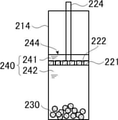
- the tip of the piston is fixed at a position lower than the liquid level of the sample liquid injected into the cylinder and higher than the superabsorbent polymer contained in the cylinder. It has a liquid holding part for holding the sample liquid existing on the tip of the piston, and has a liquid holding part.
- the super absorbent polymer is housed in the cylinder under the liquid holding portion via the piston.
- the cylinder and the piston are provided with a piston position fixing mechanism that fixes the tip of the piston to the position against the pressure associated with the water absorption expansion of the superabsorbent polymer.
- the highly water-absorbent polymer absorbs water contained in a sample liquid other than the sample liquid held in the liquid holding portion among the sample liquids injected into the cylinder, and the concentrate of the sample liquid is placed in the cylinder. Produces a sample solution concentrate and By releasing the piston position fixing mechanism and pulling up the piston, the sample liquid existing on the tip of the piston is introduced under the tip of the piston through the hole in the tip of the piston. Add the sample liquid existing on the above piston to the liquid concentrate, A concentration device that takes out a sample liquid concentrate, which is a concentrate of the sample liquid, from a hole at the tip of the piston by pulling the piston down to the cylinder again.
- the water absorption rate of the superabsorbent polymer is 0.01 g / min or more and 40 g / min or less per 1 g of the superabsorbent polymer.
- the superabsorbent polymer has a particle size of 5 mm or less.
- the concentration device according to any one of (1) to (8) above, wherein the superabsorbent polymer has a swelling rate of more than 0.2 g / g and less than 800 g / g.
- the concentrating device according to any one of (1) to (9) above, wherein the sample liquid is an aqueous solution containing a polymer contained in a biological fluid.
- the concentration device 10 above, wherein the cylinder further contains a binding substance that specifically binds to a polymer contained in the biological fluid.
- the binding substance is contained in the cylinder as a complex with metal particles.
- a method for concentrating a sample solution which comprises taking out the sample solution concentrate, which is the concentrate of the sample solution, and taking out the sample solution in this order.
- a method for inspecting a sample solution which detects a polymer in the sample solution, which is an aqueous solution containing a polymer.
- a concentration step of obtaining the sample solution concentrate and the concentration step A method for inspecting a sample solution, comprising a detection step of detecting a polymer in the obtained sample solution concentrate in this order.
- the sample liquid is an aqueous solution that can contain an antigen.
- the concentration step is a step of concentrating an aqueous solution containing the antigen using the method for concentrating the sample solution according to (16) to obtain an antigen concentrate.
- the detection step comprises an amplification step of amplifying information on the antigen in the antigen concentrate.
- the inspection method according to (19) above, wherein the amplification step is a silver amplification step.
- a test kit. (22) The test kit according to (21) above, wherein the detection device is an immunochromatography.
- the detection device comprises a pot containing an amplifying solution for amplifying a signal for detecting a polymer in the sample solution concentrate.
- a concentration device for concentrating a sample solution capable of obtaining a sample solution concentrate having a desired concentration ratio
- a method for concentrating a sample solution using the concentration device and the above sample. It is possible to provide a method for inspecting a sample liquid using a method for concentrating a liquid, and an inspection kit including the above-mentioned concentrating device.
- FIG. 1 It is a schematic sectional view of one aspect of aspect A1 of the enrichment device of this invention. It is a schematic sectional view of one aspect of aspect A2 of the enrichment device of this invention. It is a schematic sectional view of one aspect B of the enrichment device of this invention. It shows the first state in the schematic cross-sectional view which shows one aspect of the sample liquid concentration method using the aspect A1 of the concentration device of this invention in the order of a process.
- the sample liquid injection step is shown in the schematic cross-sectional view showing one aspect of the sample liquid concentration method using the aspect A1 of the concentration device of the present invention in the order of steps.
- the water absorption step is shown in the schematic cross-sectional view showing one aspect of the sample liquid concentration method using the aspect A1 of the concentration device of the present invention in the order of steps. It shows the extraction addition step in the schematic cross-sectional view which shows one aspect of the sample liquid concentration method using the aspect A1 of the concentration device of this invention in the order of a process. It shows the taking-out process in the schematic cross-sectional view which shows one aspect of the sample liquid concentration method using the aspect A1 of the concentration device of this invention in the order of a process. It shows the first state in the schematic cross-sectional view which shows one aspect of the sample liquid concentration method using the aspect A2 of the concentration device of this invention in the order of a process.
- the sample liquid injection step is shown in the schematic cross-sectional view showing one aspect of the sample liquid concentration method using the aspect A2 of the concentration device of the present invention in the order of steps.
- the water absorption step is shown in the schematic cross-sectional view showing one aspect of the sample liquid concentration method using the aspect A2 of the concentration device of the present invention in the order of steps.
- It shows the taking-out process in the schematic cross-sectional view which shows one aspect of the sample liquid concentration method using the aspect A2 of the concentration device of this invention in the order of a process.
- the sample liquid injection step is shown in the schematic cross-sectional view showing one aspect of the sample liquid concentration method using the aspect B of the concentration device of the present invention in the order of steps.
- the water absorption step is shown in the schematic cross-sectional view showing one aspect of the sample liquid concentration method using the aspect B of the concentration device of the present invention in the order of steps.
- FIG. 202-204 It shows the taking-out process in the schematic cross-sectional view which shows one aspect of the sample liquid concentration method using the aspect B of the concentration device of this invention in the order of a process.
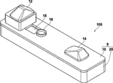
- disassembled schematic perspective view which shows the aspect of one Embodiment of an immunochromatography kit.
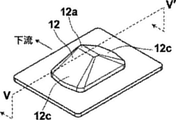
- FIG. 10 is a perspective view of a first convex deformation portion provided in the upper case of the immunochromatographic kit shown in FIG. 10.
- FIG. 13 is an end view of the VV'line cut portion before and after the deformation of the first convex deformed portion shown in FIG.
- FIG. 10 is a perspective view of a second convex deformation portion provided in the upper case of the immunochromatographic kit shown in FIG. 10.
- FIG. 15 is an end view of the VII-VII'line cut portion before and after the deformation of the second convex deformed portion shown in FIG. It is a top view of the cut portion before and after the deformation of the convex deformed portion of the design change example.
- the numerical range represented by using "-" in the present specification means a range including the numerical values before and after "-" as the lower limit value and the upper limit value.
- each component may be used alone or in combination of two or more.
- the content of the component means the total content unless otherwise specified.
- the concentration device of the present invention when the sample solution is concentrated using the concentration device of the present invention, a sample solution concentrate having a desired concentration ratio can be obtained, and the concentration of the obtained sample solution concentrate is uniform. It is also said that the effect of the present invention is excellent when the properties are high, the detection sensitivity is high, and the S / N ratio (signal / noise ratio) is high in the method for inspecting the sample liquid of the present invention. ..
- Aspect A of the enrichment device of the present invention is A concentration device for concentrating a sample solution, which is an aqueous solution containing a polymer, including a cylinder containing a superabsorbent polymer in the form of particles and a piston that can be inserted into the cylinder.
- the cylinder has a liquid holding portion (hereinafter, also referred to as “extract holding portion”) for holding a part of the sample liquid injected into the cylinder at the bottom thereof.
- the superabsorbent polymer is housed in the cylinder on the extract holding portion in contact with the extract holding portion.
- the piston comprises a tip having a hole smaller than the particle size of the superabsorbent polymer after water absorption.
- the highly water-absorbent polymer absorbs water contained in a sample liquid other than the sample liquid held in the extract holding portion among the sample liquids injected into the cylinder, and the concentrate of the sample liquid is contained in the cylinder.
- Produces a sample solution concentrate that is The sample liquid held in the extract holding portion (hereinafter, also referred to as “extract”) is added to the sample liquid concentrate, and the sample liquid is added to the sample liquid concentrate.
- Aspect A1 is the aspect A described above.
- the extract holding portion is a portion surrounded by a bottom portion of the cylinder and a partition wall movably installed on the inner peripheral surface of the cylinder in the longitudinal direction of the cylinder, and the partition wall is a superabsorbent polymer. Has pores smaller than the particle size before water absorption, By moving the partition wall to the bottom surface of the cylinder, the sample liquid held in the extract holding portion is introduced onto the partition wall through the hole of the partition wall. It is an embodiment in which the sample liquid introduced on the partition wall is added to the sample liquid concentrate.
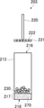
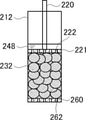
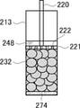
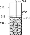
- FIG. 1 is a schematic cross-sectional view of one aspect of aspect A1.
- the concentration device 202 includes a cylinder 212 containing a superabsorbent polymer 230 and a piston 220 that can be inserted into the cylinder 212.
- the piston 220 includes a tip portion 221 having a hole 222 smaller than the particle size after water absorption of the super absorbent polymer 230.
- the cylinder 212 has a partition wall 260 movably installed on the inner peripheral surface of the cylinder 212 in the longitudinal direction of the cylinder 212. Further, the partition wall 260 has a hole 262 smaller than the particle size of the super absorbent polymer 230 before water absorption.
- the superabsorbent polymer 230 is housed in the cylinder 212 on the partition wall 260 in contact with the partition wall 260.
- the portion surrounded by the bottom portion 217 of the cylinder 212 and the partition wall 260 serves as an extract holding portion.
- a method for concentrating a sample liquor which is an aqueous solution containing a polymer, is a method for concentrating a sample liquor using the above-mentioned embodiment A1.
- water contained in the sample liquid other than the sample liquid held in the extract holding portion is absorbed by the highly water-absorbent polymer contained in the cylinder, and the above cylinder contains the above.
- a liquid addition step (hereinafter, also referred to as “extract addition step”) in which the sample liquid held in the extract holding portion is added to the sample liquid concentrate.
- extract addition step By inserting a piston that has a tip that is a piston that can be inserted into the cylinder and has a hole smaller than the particle size after water absorption of the superabsorbent polymer, the piston is passed through the hole at the tip of the piston.
- the sample liquid concentrate which is the sample liquid concentrate, is taken out and taken out in this order.
- the extract addition step moves the partition to the bottom surface of the cylinder and introduces the sample solution held in the extract holding portion onto the partition through the hole of the partition to concentrate the sample solution.
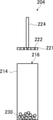
- FIG. 4 are schematic cross-sectional views showing one aspect of the method for concentrating the sample liquid using the aspect A1 in the order of steps.
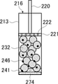
- the sample liquid 240 is injected through the opening 216 into the cylinder 212 (FIG. 4A) containing the particulate superabsorbent polymer 230 (FIG. 4B).
- the cylinder 212 has a partition wall 260 movably installed on the inner peripheral surface of the cylinder 212 in the longitudinal direction of the cylinder 212.
- the partition wall 260 has a hole 262 smaller than the particle size of the super absorbent polymer 230 before water absorption.
- the superabsorbent polymer 230 is housed in the cylinder 212 on the partition wall 260 in contact with the partition wall 260.
- the sample liquid 240 When the sample liquid 240 is injected into the cylinder 212 as described above, a part of the sample liquid 240 is introduced under the partition wall 260 through the hole 262 of the partition wall 260. Then, in the water absorption step described later, only the water contained in the sample liquid 242 existing on the partition wall 260 of the sample liquid 240 is absorbed by the super absorbent polymer 230, and is under the partition wall 260 of the sample liquid 240. The water contained in the existing sample liquid 241 is not absorbed by the super absorbent polymer 230.
- sample liquid injection step the sample liquid 240 is injected into the cylinder 212, and a part of the sample liquid (sample liquid 241) injected into the cylinder 212 is added as an extract liquid to be added in the extract liquid addition step described later.
- the partition 260 is moved to the bottom surface 218 of the cylinder 212, and the sample liquid 241 held in the extract holding portion is introduced onto the partition 260 through the hole 262 of the partition 260.
- the sample liquid 241 held in the extract holding portion is added to the liquid concentrate 246 (FIG. 4D).
- FIG. 4D by inserting the piston 220 used in the extraction step described later into the cylinder 212 from the opening 216, the superabsorbent polymer 232 is pushed down and the partition wall 260 is moved to the bottom surface 218 of the cylinder 212.
- the method of moving the partition wall 260 is not limited to this, and for example, a mechanism for moving the partition wall 260 may be provided independently of the piston 220.
- the bottom surface 218 is made movable in the longitudinal direction of the cylinder 212, the bottom surface 218 is moved to the partition wall 260, and the sample liquid 241 held in the extract holding portion is transferred to the partition wall 260.
- the sample liquid 241 held in the extract holding portion may be added to the sample liquid concentrate 246.
- the cylinder 212 has a hole 222 that is a piston that can be inserted into the cylinder 212 and is smaller than the particle size of the superabsorbent polymer 230 after water absorption (the particle size of the swollen superabsorbent polymer 232).
- the sample liquid concentrate 248, which is the concentrate of the sample liquid 240 is taken out through the hole 222 of the tip portion 221 of the piston 220 (FIG. 4E).
- sample liquid injection step is a step of injecting the sample liquid into the cylinder and holding a part of the sample liquid injected into the cylinder in the extract holding unit.
- the shape of the cylinder is not particularly limited, but it is preferably cylindrical.
- the cylinder is usually longitudinally closed at one end (bottom surface) and open at the other end (opening).
- the material of the cylinder is not particularly limited, but it is preferably a thermoplastic resin because it can be injection molded, is inexpensive, and can be mass-produced. Since it has a certain degree of hardness, specifically, polypropylene, acrylic, polyacetal, polyamide, polyethylene, polyethylene terephthalate, polycarbonate, polystyrene, polyphenylene sulfide, polybutylene terephthalate, polyvinyl chloride, and ABS resin (acrylonitrile-butadiene-styrene) Polymer resin) and AS resin (acrylonitrile-styrene copolymer resin) are preferable.
- a thermoplastic resin because it can be injection molded, is inexpensive, and can be mass-produced. Since it has a certain degree of hardness, specifically, polypropylene, acrylic, polyacetal, polyamide, polyethylene, polyethylene terephthalate, polycarbonate, polystyrene, polyphenylene sulfide, polybutylene tere
- the superabsorbent polymer (SAP) in the form of particles contained in the cylinder is not particularly limited, but for the reason that the effect of the present invention is more excellent, polyacrylic acid-based, polyacrylamide-based, cellulosic-based, or It is preferably a polyethylene oxide-based polymer.
- the swelling rate of the superabsorbent polymer is not particularly limited, but it is preferably more than 0.2 g / g and less than 800 g / g, preferably 1.0 g / g or more and 600 g / g, for the reason that the effect of the present invention is more excellent. It is more preferably 10 g / g or more and 500 g / g or less, and particularly preferably 20 g / g or more and 100 g / g or less.
- the swelling rate is a value defined as "mass (g) of water held by 1 g of superabsorbent polymer".
- the method of adjusting the swelling rate to the above-mentioned specific range is not particularly limited, and examples thereof include changing the type of polymer, changing the molecular weight of the polymer, changing the degree of cross-linking, and changing the particle size.
- the water absorption rate of the superabsorbent polymer is not particularly limited, but for the reason that the effect of the present invention is more excellent, it is preferably 0.01 g / min or more and 40 g / min or less per 1 g of the superabsorbent polymer, and the superabsorbent polymer is highly absorbent. More preferably, it is 0.02 g / min or more and 40 g / min or less per 1 g of the polymer.
- the water absorption rate is measured as follows.
- the mass of the superabsorbent polymer stored at 25 ° C. and 5% RH (relative humidity) for 10 days is measured (weight M 0 , unit g), and then immediately immersed in a large amount of distilled water. After 10 minutes, the superabsorbent polymer is removed, surface water is removed and the mass is measured (mass M 10 ). Immediately after mass measurement, reimmerse in a large amount of distilled water. After 10 minutes, the superabsorbent polymer is taken out, the water on the surface is removed, and the mass is measured again (mass M 20 ). Immediately after measuring the mass M 20 , it is immersed again in a large amount of distilled water. After 10 minutes, the superabsorbent polymer is removed, the water on the surface is removed, and the weight is measured again (mass M 30 ).
- the particle size of the superabsorbent polymer is preferably 10 mm or less, more preferably 8 mm or less, still more preferably 5 mm or less, for the reason that the effect of the present invention is more excellent.
- the lower limit of the particle size of the superabsorbent polymer is preferably 0.01 mm or more, more preferably 0.1 mm or more, and more preferably 1 mm or more because the effect of the present invention is more excellent. More preferred.
- the particle diameter can be obtained as an arithmetic average value obtained by measuring the diameters of 50 particulate polymers with an optical microscope.
- the cylinder preferably further contains a binding substance that specifically binds to the polymer contained in the biological fluid in the sample liquid described later.
- the binding substance for example, the antigen-antibody reaction proceeds at the same time as the concentration of the sample solution, and the complex of the antigen and the labeled antibody in the sample solution is formed in a concentrated state to improve the detection sensitivity. It leads to.
- the binding substance include a first binding substance (particularly an antibody) described later.
- the polymer contained in the biological fluid is an antigen and the binding substance is an antibody because the effect of the present invention is more excellent.
- the binding substance is preferably contained in the cylinder as a complex with a labeling substance because the effect of the present invention is more excellent.
- the complex include labeled antibodies.
- the labeled antibody is an antibody to which a detectable labeling substance is bound, and the labeling substance is, for example, a detectable substance, and a directly detectable substance, for example, color.
- a substance that can generate electromagnetic waves such as fluorescence and light, or a substance that can scatter electromagnetic waves such as color, fluorescence, and light.
- the labeled antibody is preferably an antibody modified with metal particles that exhibit a vivid color tone by irradiation with an electromagnetic wave such as visible light because the effect of the present invention is more excellent.
- the metal particles are more preferably gold particles because the effects of the present invention are more excellent.
- the labeled antibody is preferably an antibody labeled with gold particles, that is, gold particles modified with the antibody (modified gold particles described later) for the reason that the effect of the present invention is more excellent.
- the labeled antibody may be contained in the cylinder as a pad (gold colloid holding pad) in which the modified gold colloid particles, which are gold colloid particles modified with the antibody, are held.
- the cylinder preferably contains at least one selected from the group consisting of casein and tricine, and more preferably contains both casein and tricine, for the reason that the effects of the present invention are more excellent.
- Casein is thought to have a function of suppressing false positives. Further, when the pH of the sample liquid such as urine is higher than acidic, false positives are likely to occur, and it is considered that tricine has a function of adjusting the pH to neutral to alkaline to suppress false positives.
- the piston includes an extract holding portion.
- the extract holding portion is a portion surrounded by a bottom portion of the cylinder and a partition wall movably installed on the inner peripheral surface of the cylinder in the longitudinal direction of the cylinder.
- the partition wall has pores smaller than the particle size of the superabsorbent polymer described above before water absorption.
- the material of the partition wall is not particularly limited, and the preferred embodiment thereof is the same as that of the cylinder described above.
- the partition wall has pores smaller than the particle size of the superabsorbent polymer described above before water absorption. Therefore, the super absorbent polymer does not fall under the partition wall.
- the diameter of the pores of the partition wall is preferably 2/3 or less of the particle diameter of the superabsorbent polymer before water absorption because the effect of the present invention is more excellent.
- the diameter of the hole of the partition wall is preferably 0.05 to 5 mm, more preferably 0.1 to 3 mm, and 0.2 to 2 mm for the reason that the effect of the present invention is more excellent. Is even more preferable.
- the number of holes in the partition wall of the tip portion is not particularly limited, but is preferably 10 to 100, more preferably 20 to 50.
- the ratio of the total area of the holes of the partition wall to the area of the partition wall is preferably 5% or more, more preferably 10% or more, and more preferably 15% or more, for the reason that the effect of the present invention is more excellent. It is more preferable to have.
- the sample liquid is an aqueous solution containing a polymer.
- an aqueous solution containing a polymer contained in a biological fluid is preferable.
- Specific examples of the sample fluid include body fluids of animals (particularly humans) (for example, blood, serum, plasma, spinal fluid, tear fluid, sweat, urine, pus, runny nose, or sputum), mouthwash, and the like. can.
- serum, plasma, urine, and nasal discharge are preferable as the sample containing the antigen as a polymer, and urine is particularly preferable because the effect of the present invention is more excellent.
- the polymer (particularly antigen) contained in the biofluid is, for example, a polymer mainly useful for determining a disease, and is used for bacteria and bacteria (for example, tubercle bacillus and tubercle bacillus) detected in the biofluid. Included are lipoarabinomannan (LAM)), bacteria, viruses (eg, influenza virus), their nuclear proteins and the like. LAM is a major antigen in tuberculosis and a glycolipid which is a major constituent of cell membranes and cell walls.
- LAM lipoarabinomannan
- the polymer contained in the biological fluid is preferably an antigen, more preferably a virus (particularly influenza virus) or LAM, and more preferably LAM, for the reason that the effect of the present invention is more excellent. More preferred.
- the molecular weight of the polymer contained in the biological fluid is preferably 1000 or more, and more preferably 2000 or more, for the reason that the effect of the present invention is more excellent.
- a theoretical value calculated from the structural formula can be used when the polymer is useful for determining a disease and the structural formula is known. If the structural formula has not been determined, it can be calculated by comparison with a substance having a known molecular weight using electrophoresis, or by liquid chromatography-mass spectrometry (LC-MS). be.
- the above sample solution is obtained by extracting the sample solution as it is or by extracting the antigen with an appropriate extraction solvent, and further, diluting the extracted solution with an appropriate diluent. It can be used in the form of a diluted solution obtained in the above-mentioned method, or in the form of a concentrated solution obtained by extraction by an appropriate method.
- the extraction solvent the solvent used in the usual immunological analysis method (for example, water, physiological saline, buffer solution, etc.) or the direct antigen-antibody reaction is carried out by diluting with such a solvent. It is also possible to use a water-miscible organic solvent that can be used.
- the ratio of the superabsorbent polymer to the sample liquid is not particularly limited, but is preferably 0.01 to 100 g per 1 mL of the sample liquid, preferably 0.1 to 100 g, for the reason that the effect of the present invention is more excellent. It is more preferably 50 g.
- sample liquid concentrate As described above, in the water absorption step, a sample liquid concentrate, which is a sample liquid concentrate, is generated in the cylinder.
- the sample liquid and the superabsorbent polymer are mixed, the water in the sample liquid is taken up by the superabsorbent polymer, whereas the polymer in the sample liquid (for example, an antigen) has a certain hydrodynamic radius. Therefore, the network structure on the surface of the super absorbent polymer produces a sieving effect, and it is difficult to be incorporated into the superabsorbent polymer. As a result, macromolecules (eg, antigens) in the sample fluid are concentrated.
- the sample liquid concentrate usually exists in the vicinity of the highly water-absorbent polymer as a polymer precipitate or a high-concentration solution of the polymer dissolved in a trace amount of residual liquid.
- the extract addition step is a step of adding the sample liquid held in the extract holding portion to the sample liquid concentrate produced in the water absorption step described above.
- the extract has a role of extracting (taking out) the sample liquid concentrate produced in the water absorption step.
- the method of adding the extract is to push down the superabsorbent polymer 232 and move the partition wall to the bottom surface of the cylinder 212 by inserting the piston used in the taking-out step described later into the cylinder from the opening of the cylinder.
- Examples thereof include a method of providing a mechanism for moving the partition wall independently of the piston, a method of making the bottom surface movable in the longitudinal direction of the cylinder 212 instead of moving the partition wall, and a method of moving the bottom surface 218 to the partition wall 260.
- the ratio (extract / sample liquid) of the amount of the extract (sample liquid held in the extract holding portion) to the amount of the sample liquid injected into the cylinder may be less than 100% by volume, but the present invention. It is preferably 30% or less, more preferably 20% or less, still more preferably 1% or more and 10% or less, for the reason that the effect of the above is more excellent.
- the cylinder after the water absorption step is provided with a piston having a tip that is a piston that can be inserted into the cylinder and has a hole smaller than the particle size of the highly water-absorbent polymer after water absorption.
- This is a step of taking out the sample liquid concentrate, which is the concentrate of the sample liquid, through the hole at the tip of the piston by inserting the piston.
- a piston is inserted into the cylinder and the tip having a hole is pushed against the super absorbent polymer. At this time, since the extract collects upward while moving all over the gaps of the super absorbent polymer, a uniform sample liquid concentrate can be obtained by the stirring effect at this time.
- the piston is a piston that can be inserted into a cylinder and has a tip having a hole smaller than the particle size of the superabsorbent polymer described above after water absorption.
- the material of the piston is not particularly limited, and the preferred embodiment thereof is the same as that of the cylinder described above.
- the tip of the piston has a hole smaller than the particle size of the superabsorbent polymer described above after water absorption.
- the particle size of the superabsorbent polymer after water absorption can be obtained by measuring the diameters of 50 particulate polymers and using the arithmetic mean value thereof.
- the diameter of the hole at the tip is preferably 1/2 or less, and more preferably 1/5 or less, the particle diameter of the superabsorbent polymer after water absorption, for the reason that the effect of the present invention is more excellent. It is preferably 1/10 or less, and more preferably 1/10 or less.
- the diameter of the hole at the tip thereof is preferably smaller than the particle diameter of the superabsorbent polymer before water absorption because the effect of the present invention is more excellent.
- the diameter of the hole at the tip is preferably 0.01 to 5 mm, more preferably 0.1 to 2, for the reason that the effect of the present invention is more excellent.
- the number of holes possessed by the tip portion is not particularly limited, but is preferably 10 to 100, more preferably 20 to 50.
- the ratio of the total area of the holes in the tip to the area of the tip is preferably 5% or more, more preferably 10% or more, and more preferably 15%, for the reason that the effect of the present invention is more excellent. The above is more preferable.
- sample liquid concentrate As described above, in the take-out step, a sample liquid concentrate is obtained.
- the amount of sample solution concentrate is approximately the amount of extract. That is, the concentration ratio of the sample liquid concentrate is approximately the sample liquid / extract. Therefore, by keeping the amount of the sample liquid and the extract (the sample liquid held in the extract holding part) constant (the amount of the sample liquid injected into the cylinder and the amount of the extract holding part). In), a sample solution concentrate having a desired concentration ratio can be obtained.
- Aspect A2 is the aspect A described above.
- the extract holding portion is a portion formed by pores of the porous resin housed in the bottom of the cylinder, and the pores of the resin are smaller than the particle size of the superabsorbent polymer before water absorption. , When the resin is crushed, the sample liquid held in the extract holding portion is introduced onto the resin through the holes of the resin. In this embodiment, the sample liquid introduced onto the resin is added to the sample liquid concentrate.
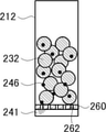
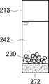
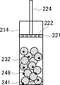
- FIG. 2 is a schematic cross-sectional view of one aspect of aspect A2.
- the concentration device 203 includes a cylinder 213 containing a superabsorbent polymer 230 and a piston 220 that can be inserted into the cylinder 213.
- the piston 220 includes a tip portion 221 having a hole 222 smaller than the particle size after water absorption of the super absorbent polymer 230.
- the porous synthetic resin 270 is housed in the bottom 217 of the cylinder 213. Further, the pores (not shown) of the synthetic resin 270 are smaller than the particle size of the superabsorbent polymer 230 before water absorption.
- the superabsorbent polymer 230 is housed in the cylinder 213 in contact with the synthetic resin 270 on the synthetic resin 270.
- the pores of the synthetic resin 270 serve as an extract holding portion.
- a method for concentrating a sample solution which is an aqueous solution containing a polymer, is a method for concentrating a sample solution using the above aspect A2.
- water contained in the sample liquid other than the sample liquid held in the extract holding portion is absorbed by the highly water-absorbent polymer contained in the cylinder, and the above cylinder contains the above.
- a liquid addition step (hereinafter, also referred to as “extract addition step”) in which the sample liquid held in the extract holding portion is added to the sample liquid concentrate.
- extract addition step By inserting a piston that has a tip that is a piston that can be inserted into the cylinder and has a hole smaller than the particle size after water absorption of the superabsorbent polymer, the piston is passed through the hole at the tip of the piston.
- the sample liquid concentrate which is the sample liquid concentrate, is taken out and taken out in this order.
- the extract addition step crushes the resin and introduces the sample liquid held in the extract holding portion onto the resin through the pores of the resin, whereby the extract is added to the sample liquid concentrate.
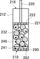
- FIGS. 5A to 5E are schematic cross-sectional views showing one aspect of the aspect A2 in the order of processes.
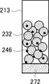
- the sample liquid is injected from the opening 216 into the cylinder 213 (FIG. 5A) containing the particulate superabsorbent polymer 230 (FIG. 5B).
- the bottom 217 of the cylinder 213 contains the porous synthetic resin 270.
- the pores (not shown) of the synthetic resin 270 are smaller than the particle size of the superabsorbent polymer 230 before water absorption.
- the superabsorbent polymer 230 is housed in the cylinder 213 in contact with the synthetic resin 270 on the synthetic resin 270.
- the synthetic resin 270 is a sample liquid 241 (not shown) which is a part of the sample liquid. It becomes the synthetic resin 272 introduced into the pores).
- the water absorption step described later only the water contained in the sample liquid 242 existing on the synthetic resin 270 of the sample liquid is absorbed by the highly water-absorbent polymer 230, and the pores of the synthetic resin 270 in the sample liquid are absorbed.
- the water contained in the existing sample liquid 241 is not absorbed by the highly water-absorbent polymer 230.
- sample liquid injection step the sample liquid is injected into the cylinder 213, and a part of the sample liquid (sample liquid 241) injected into the cylinder 213 is used as an extract liquid to be added in the extract liquid addition step described later.
- the water contained in the sample liquid 242 (the sample liquid 242 of the sample liquid 240 other than the sample liquid 241 held in the extract holding portion) existing on the synthetic resin 270 of the sample liquid 240). Only is absorbed by the highly water-absorbent polymer 230 to produce a sample liquid concentrate 246 in the cylinder 213, which is a concentrate of the sample liquid 242 (the highly water-absorbent polymer 230 becomes a swollen, highly water-absorbent polymer 232) ( FIG. 5C).
- the synthetic resin 270 is crushed, and the sample liquid 241 held in the extract holding portion is introduced onto the synthetic resin 270 through the pores of the synthetic resin 270, whereby the sample liquid concentrate 246 is introduced.
- the sample liquid 241 held in the extract holding portion is added to the above (FIG. 5D).
- the piston 220 used in the take-out step described later is inserted into the cylinder 213 from the opening 216 to push down the superabsorbent polymer 232 and crush the synthetic resin 270.
- the method for crushing the resin 270 is not limited to this, and for example, a mechanism for crushing the synthetic resin 270 may be provided independently of the piston 220.
- the cylinder 213 has a hole 222 that is a piston that can be inserted into the cylinder 213 and is smaller than the particle size of the superabsorbent polymer 230 after water absorption (the particle size of the swollen superabsorbent polymer 232).
- the sample liquid concentrate 248, which is the concentrate of the sample liquid 240 is taken out through the hole 222 of the tip portion 221 of the piston 220 (FIG. 5E).
- sample solution injection process The sample liquid injection step is the same as the sample liquid injection step of the method for concentrating the sample liquid using the above-mentioned aspect A1 except that the extract holding portion has the following configuration.
- the piston includes an extract holding portion.
- the extract holding portion is a portion formed by the pores of the porous resin housed in the bottom of the cylinder.
- the pores of the resin are smaller than the particle size of the superabsorbent polymer described above before water absorption. Therefore, the super absorbent polymer does not enter the resin.
- the resin either a naturally occurring resin or a synthetic resin can be used, but a synthetic resin is preferable from the viewpoint of ease of molding and mass production at low cost.
- the material of the synthetic resin is not particularly limited, and specific examples thereof include polyvinyl alcohol (PVA).
- PVA polyvinyl alcohol
- the resin is preferably a sponge because the effect of the present invention is more excellent.
- the pores of the resin are smaller than the particle size of the superabsorbent polymer described above before water absorption. Therefore, the super absorbent polymer does not enter the resin.
- the porosity of the resin is not particularly limited, but is preferably 50% or more, preferably 70% or more and 99% or less, for the reason that the effect of the present invention is more excellent. It is more preferable that it is 70% or more and 98% or less.
- the water absorption step is the same as the water absorption step of the method for concentrating the sample liquid using the above-mentioned aspect A1.
- the extract addition step is a step of adding the sample liquid held in the extract holding portion to the sample liquid concentrate produced in the water absorption step described above.
- the extract has a role of extracting (taking out) the sample liquid concentrate produced in the water absorption step.
- the method of adding the extract is a method of pushing down the superabsorbent polymer by inserting a piston used in the extraction step described later into the cylinder from the opening to crush the porous resin. Examples thereof include a method in which a mechanism for crushing the resin is provided independently of the piston.
- the take-out step is the same as the take-out step of the method for concentrating the sample liquid using the above-mentioned aspect A1.
- Aspect B of the enrichment device of the present invention is A concentration device for concentrating a sample liquid, which is an aqueous solution containing a polymer, including a cylinder containing a superabsorbent polymer in the form of particles and a piston that can be inserted into the cylinder.
- the piston comprises a tip having a hole smaller than the particle size of the superabsorbent polymer after water absorption.
- extract holding part for holding the sample liquid existing on the tip of the piston among the sample liquid injected into the cylinder.
- the superabsorbent polymer is housed in the cylinder under the extract holding portion via the piston.
- the cylinder and the piston are provided with a piston position fixing mechanism that fixes the tip of the piston to the position against the pressure associated with the water absorption expansion of the superabsorbent polymer.
- the highly water-absorbent polymer absorbs water contained in a sample liquid other than the sample liquid held in the extract holding portion among the sample liquids injected into the cylinder, and the concentrate of the sample liquid is contained in the cylinder.
- FIG. 3 is a schematic cross-sectional view of one aspect of aspect B.
- the concentration device 204 includes a cylinder 214 containing the superabsorbent polymer 230 and a piston 224 that can be inserted into the cylinder 214.
- the piston 220 has holes smaller than the particle size of the superabsorbent polymer 230 after water absorption.
- the piston 224 includes a tip portion 221 having a hole 222 smaller than the particle size after water absorption of the super absorbent polymer 230.
- the cylinder 214 and the piston 224 include a piston position fixing mechanism (not shown) that fixes the tip portion 221 of the piston 224 to the position A against the pressure due to the water absorption expansion of the superabsorbent polymer 230.
- a piston position fixing mechanism (not shown) that fixes the tip portion 221 of the piston 224 to the position A against the pressure due to the water absorption expansion of the superabsorbent polymer 230.
- the method for concentrating a sample solution which is an aqueous solution containing a polymer, is a method for concentrating a sample solution using the above aspect B.
- water contained in the sample liquid other than the sample liquid held in the extract holding portion is absorbed by the highly water-absorbent polymer contained in the cylinder, and the above cylinder contains the above.
- a liquid addition step (hereinafter, also referred to as “extract addition step”) in which the sample liquid held in the extract holding portion is added to the sample liquid concentrate,
- extract addition step By inserting a piston that has a tip that is a piston that can be inserted into the cylinder and has a hole smaller than the particle size after water absorption of the superabsorbent polymer, the piston is passed through the hole at the tip of the piston.
- the sample liquid concentrate which is the sample liquid concentrate, is taken out and taken out in this order.
- the sample liquid injection step the sample liquid is injected into the cylinder, the piston is inserted into the cylinder, and the piston is housed in the cylinder lower than the liquid level of the sample liquid injected into the cylinder.
- the extract addition step is present in the sample liquid concentrate on the piston by pulling up the piston and introducing the sample liquid existing on the piston under the piston through the hole of the piston.
- This is a method for concentrating a sample liquid which is a step of adding a sample liquid to be used.
- FIG. 6 is a schematic cross-sectional view showing one aspect of the aspect B in the order of processes.
- the sample liquid 240 is injected through the opening 216 into the cylinder 214 (FIG. 6A) containing the highly water-absorbent polymer 230 in the form of particles, and the piston that can be inserted into the cylinder 214 is injected into the cylinder 214.
- a piston 224 having a tip portion 221 having a hole 222 smaller than the particle size of the highly water-absorbent polymer 230 after water absorption is inserted, and the tip portion 221 of the piston 224 is injected into the cylinder 214 of the sample liquid 240.
- the cylinder 214 and the piston 224 are provided with a piston position fixing mechanism (not shown) that fixes the tip portion 221 of the piston 224 to the position A against the pressure due to the water absorption expansion of the superabsorbent polymer 230. ..
- a part of the sample liquid is the tip portion 221 of the piston 224.
- the piston 224 is inserted into the cylinder 214 and the tip portion 221 of the piston 224 is fixed at the position A, so that the tip portion 221 of the piston 224 out of the sample liquid 240 injected into the cylinder 214.
- the sample liquid 242 (the sample liquid 242 other than the sample liquid 241 held as the extract liquid in the sample liquid 240) existing under the tip portion 221 of the piston 224 in the sample liquid 240. Only water is absorbed by the highly water-absorbent polymer 230 to produce a sample liquid concentrate 246 in the cylinder 214, which is a concentrate of the sample liquid 242 (the high water-absorbent polymer 230 becomes a swollen high-water-absorbent polymer 232). (Fig. 6C).
- the piston 224 is pulled up and the sample liquid 241 existing on the tip portion 221 of the piston 224 is introduced under the tip portion 221 of the piston 224 through the hole 222 of the tip portion 221 of the piston 224.
- the sample liquid 241 present on the tip portion 221 of the piston 224 is added to the sample liquid concentrate 246 (FIG. 6D).
- sample solution injection process The sample liquid injection step is the same as the sample liquid injection step of the method for concentrating the sample liquid using the above-mentioned aspect A1 except that the extract holding portion has the following configuration.
- the water absorption step is the same as the water absorption step of the method for concentrating the sample liquid using the above-mentioned aspect A1.
- the extract addition step is a step of adding the sample solution held in the extract holding portion to the sample solution concentrate produced in the water absorption step described above.
- the extract has a role of extracting (taking out) the sample liquid concentrate produced in the water absorption step.
- a method of adding the extract a method of pulling up the piston and introducing the sample liquid existing above the tip of the piston through the hole of the tip of the piston and below the tip of the piston can be mentioned. ..
- the ratio (extract / sample liquid) of the amount of the extract (sample liquid held in the extract holding portion) to the amount of the sample liquid injected into the cylinder the method for concentrating the sample liquid using the above-mentioned embodiment A1. It is the same as the extract addition step of.
- the take-out step is the same as the take-out step of the method for concentrating the sample liquid using the above-mentioned aspect A1.
- the cylinder and the piston fix the tip of the piston at the position A described above against the pressure due to the water absorption expansion of the superabsorbent polymer described above. Equipped with a fixing mechanism.
- the piston position fixing mechanism is not particularly limited, but for example, as shown in Example 3 (FIG. 8) described later, the cylinder is provided with a notch, the piston is provided with a protrusion, the piston is inserted into the cylinder, and the piston is used. By hooking the protrusion on the notch of the cylinder, the tip of the piston can be fixed at the position A against the pressure associated with the water absorption expansion of the superabsorbent polymer.
- the concentration device of the present invention (Aspect A, Aspect B) further has a collection port for collecting the above-mentioned sample liquid concentrate for the reason that the effect of the present invention is more excellent. It is preferable to have a lid. Specific embodiments of the lid include, for example, a lid (FIG. 7) as used in Example 1 described later.
- a lid FIG. 7
- Method for Concentrating Sample Liquid The method for concentrating the sample liquid of the present invention (hereinafter, also referred to as "concentration method of the present invention") is as described above.
- the method for inspecting the sample solution of the present invention is A method for inspecting a sample solution, which detects a polymer in the sample solution, which is an aqueous solution containing a polymer.
- the concentration step of obtaining the above-mentioned sample solution concentrate is an inspection method comprising a detection step of detecting a polymer in the obtained sample liquid concentrate in this order.
- the polymer is detected using the sample liquid concentrate obtained by the above-mentioned concentration method of the present invention, so that high detection sensitivity can be obtained.
- the detection step is a step of detecting a polymer in the sample liquid concentrate.
- the detection step is preferably a method using an antigen-antibody reaction because the effect of the present invention is more excellent, and examples of such a method include an enzyme-linked immunosorbent assay (EIA) and a solid phase enzyme-linked immunosorbent assay (EIA).
- EIA enzyme-linked immunosorbent assay
- EIA solid phase enzyme-linked immunosorbent assay
- ELISA enzyme-linked immunosorbent assay
- RIA radioimmunoassay
- FIA fluorescent immunoassay
- western blot immunochromatography and the like.
- immunochromatography is preferable because the effects of the present invention are more excellent.
- the inspection method of the present invention is for the reason that the effect of the present invention is more excellent.
- the sample liquid is an aqueous solution that can contain an antigen (polymer).
- the concentration step is a step of concentrating an aqueous solution containing the antigen using the concentration method of the present invention described above to obtain an antigen concentrate (sample solution concentrate).
- the detection step is a test method, which is a step of detecting an antigen in the antigen concentrate by immunochromatography using an antigen-antibody reaction.
- the detection step is performed because the effect of the present invention is more excellent.
- the antigen in a state where a gold particle complex, which is a complex of the antigen in the antigen concentrate and the modified gold particles, which are gold particles modified with a first binding substance capable of binding to the antigen, is formed.
- the above detection step is performed because the effect of the present invention is more excellent. Further, it is preferable to include a silver amplification step of amplifying the gold particle complex captured in the capture step with silver.
- At least one of the first binding substance and the second binding substance is preferably a monoclonal antibody, and the first binding substance and the second binding substance are used. It is more preferred that both binding agents are monoclonal antibodies.
- the sample liquid may contain impurities such as salt.
- impurities such as salt.
- the sample liquid when the sample liquid is urine, it contains impurities of low molecular weight components such as urea. From the studies by the present inventors, it has been found that when these impurities are concentrated together with the polymer contained in the biological fluid, the antigen-antibody reaction may be inhibited and the detection sensitivity may be lowered. ing. That is, it is known that the effect of improving the detection sensitivity by concentration may not be sufficiently obtained. Therefore, in the above-mentioned concentration device of the present invention used in the above-mentioned concentration step, the swelling rate of the superabsorbent polymer is preferably in the above-mentioned preferable range capable of sufficiently absorbing impurities and the like.
- the developing step is a gold particle which is a complex of an antigen in the antigen concentrate obtained in the above-mentioned concentration step and modified gold particles which are gold particles modified with a first binding substance capable of binding to the antigen.
- This is a step of developing a second binding substance capable of binding to the antigen on an insoluble carrier having an immobilized reaction site in a state where the complex is formed.
- the antigen in the antigen concentrate obtained in the above-mentioned concentration step and the modified gold particles, which are gold particles modified with the first binding substance capable of binding to the antigen, are used.
- a gold particle complex, which is a complex, is formed.
- the antigen concentrate may be simply developed on the insoluble carrier as it is.
- the modified gold particles are gold particles modified with a first binding substance capable of binding to the antigen.
- Gold particles are not particularly limited, but are preferably colloidal gold particles for the reason that the effects of the present invention are more excellent.
- the gold particles act as a catalyst for reducing silver ions in the silver amplification step.
- the particle size of the gold particles is preferably 500 nm or less, more preferably 300 nm or less, further preferably 200 nm or less, still more preferably 100 nm or less, for the reason that the effect of the present invention is more excellent. Is particularly preferable.
- the lower limit of the particle size of the gold particles is not particularly limited, but it is preferably 1 nm or more, more preferably 2 nm or more, still more preferably 5 nm or more, for the reason that the effect of the present invention is more excellent. ..
- the particle size can be measured with a commercially available particle size distribution meter or the like.
- Particle size distribution measurement methods include optical microscopy, confocal laser microscopy, electron microscopy, interatomic force microscopy, static light scattering, laser diffraction, dynamic light scattering, centrifugal sedimentation, and electrical pulses. Measurement methods, chromatography methods, ultrasonic attenuation methods, etc. are known, and devices corresponding to each principle are commercially available.
- a dynamic light scattering method can be preferably used because of the particle size range and ease of measurement.
- Nanotrack UPA Nikkiso Co., Ltd.
- dynamic light scattering type particle size distribution measuring device LB-550 HORIBA, Ltd.
- the first binding substance is not particularly limited as long as it can bind to the antigen, but it is preferably a protein and an antibody (for example, for example) because the effect of the present invention is more excellent. , Polyclonal antibody, or monoclonal antibody) is more preferable, and a monoclonal antibody is further preferable from the viewpoint of achieving higher detection sensitivity.
- the above antibody is not particularly limited, but for example, an antiserum prepared from the serum of an animal immunized with the antigen, an immunoglobulin fraction purified from the antiserum can be used, and the antibody is immunized with the antigen.
- Monoclonal antibodies obtained by cell fusion using animal spleen cells or fragments thereof [eg, F (ab') 2, Fab, Fab', or Fv] can be used. Preparation of these antibodies can be carried out by a conventional method.
- the first binding substance when the antigen is influenza virus
- a commercially available antibody can be used, for example, an anti-influenza A type monoclonal antibody (Anti-Influenza A SPTN-5 7307, Medix Biochemica), and the like.
- An anti-influenza A type monoclonal antibody (manufactured by Bios Pacific, clone number: A60010044P) can be mentioned.
- the A194-01 antibody described in International Publication No. 2017/139153 can be mentioned. All the content of International Publication No. 2017/139153 relating to A194-01 antibody is incorporated herein by reference as part of the disclosure herein.
- an antibody having a sequence described as MoAb1 in paragraph number [0080] of International Publication No. 2013/12963 can be mentioned. All of the content described in WO 2013/129634 relating to MoAb1 antibodies is incorporated herein by reference as part of the disclosure herein.
- the method for producing the modified gold particles is not particularly limited, and a known method can be used.
- a known method can be used.
- the SH bond is cleaved when approaching the gold particles and immobilized by the Au-S bond generated on the Au surface. Examples thereof include chemical bonding methods such as causing.
- the insoluble carrier is an insoluble carrier having a reaction site (test line) on which a second binding substance capable of binding to the antigen is immobilized.
- the insoluble carrier may have a plurality of test lines depending on the type of antigen (for example, a test line for influenza A virus and a test line for influenza B virus). Further, the insoluble carrier may have a control line on the downstream side of the test line in order to confirm the development of the gold particle complex. Further, when the reducing agent liquid is used in the silver amplification step described later, a color-developing reagent immobilization line may be provided on the downstream side of the test line in order to detect the reducing agent liquid.
- the insoluble carrier for example, as shown in FIG. 9, a nitrocellulose membrane having a gold colloid holding pad 301, a test line 302, a control line 303, and a color-developing reagent immobilization line 304 from the upstream side. 300 is mentioned.
- the gold colloid holding pad 301 is a pad for holding gold particles (modified gold particles) modified with the first binding substance
- the test line 302 is a line on which the second binding substance is immobilized.
- the control line 303 is a line for confirming the development
- the color-developing reagent immobilization line 304 is a line for detecting the reducing agent solution described later.
- the upstream side and the downstream side mean a description intended to be developed from the upstream side to the downstream side when the gold particle complex is developed.
- the insoluble carrier or an immunochromatographic kit having the same
- the insoluble carrier and the immunochromatographic kit described in Japanese Patent No. 5728453 can be mentioned, and the patent No. 1 relating to the insoluble carrier and the immunochromatographic kit can be mentioned. All of the content described in Japanese Patent Publication No. 5728453 is incorporated herein by reference as part of the disclosure herein.
- the insoluble carrier is preferably a porous carrier.
- a nitrocellulose membrane nitrocellulose membrane
- a cellulose membrane an acetylcellulose membrane, a polysulfone membrane, a polyethersulfone membrane, a nylon membrane, a glass fiber, a non-woven fabric, a cloth, or a thread, etc. Is preferable, and a nitrocellulose membrane is more preferable.
- the second binding substance is not particularly limited as long as it can bind to the antigen.
- Specific examples and suitable embodiments of the second binding substance include, for example, the same as the specific examples and preferred embodiments described in the first binding substance described above.
- the second binding substance may be the same as or different from the first binding substance described above, but it is preferable that the second binding substance is a different substance for the reason that the effect of the present invention is more excellent.
- the first binding substance and the second binding substance are antibodies, the antibody which is the first binding substance and the antibody which is the second binding substance are different for the reason that the effect of the present invention is more excellent. Aspects are preferred.
- the epitope of the first binding substance (a part of the antigen recognized by the first binding substance) and the epitope of the second binding substance (the first).
- a different embodiment of the antigen recognized by the binding substance (2) is preferable because the effect of the present invention is more excellent.
- the difference in the epitope of the antibody can be confirmed by, for example, ELISA (Enzyme-Linked Immuno Substance Assay).
- the method of developing the gold particle complex on an insoluble carrier having a test line in a state of being formed is not particularly limited, and for example, a nitrocellulose membrane 300 (or an immunochromatographic kit having the same) as shown in FIG. 9 described above). And the method of dropping the antigen concentrate obtained in the above-mentioned concentration step onto the gold colloid holding pad and moving it from the upstream side to the downstream side by using the capillary phenomenon as shown in FIG. Will be.
- the capture step is a step of capturing the gold particle complex at the reaction site of the insoluble carrier.
- the gold particle complex (antigen and modified gold particles) developed on the insoluble carrier in the above developing step. Complex) is captured at the reaction site (test line) of the insoluble carrier.
- the captured gold particle complex is visible because it is colored by the surface plasmon of the gold particles. It is also possible to estimate the concentration of the captured complex using an image analysis device or the like. In this way, the antigen in the sample can be detected.
- the gold particle complex is not formed, so that the sample is not captured at the reaction site of the insoluble carrier and is not colored.
- the silver amplification step is a step of silver-amplifying the gold particle complex captured in the capture step.
- the silver amplification step is a step of forming large silver particles in the gold particle complex captured at the reaction site of the insoluble carrier by imparting silver ions to the insoluble carrier after the capture step. More specifically, it is a step in which silver ions are reduced using the gold particles of the gold particle complex as a catalyst to form silver particles (for example, a diameter of 10 ⁇ m or more). This significantly improves the detection sensitivity of the captured gold particle complex.
- the silver amplification step may be performed together with the development step, and the silver amplification step may also serve as the development step.
- the method of imparting silver ions to the insoluble carrier after the capture step is not particularly limited, but a method of using the following reducing agent solution and the following silver amplification solution is preferable for the reason that the effect of the present invention is more excellent. Further, in addition to the reducing agent solution and the silver amplification solution, a washing solution may be used to wash the complex remaining on the insoluble carrier other than the specific binding reaction.
- the reducing liquid may also serve as a cleaning liquid.
- the reducing agent solution contains a reducing agent capable of reducing silver ions.
- the reducing agent capable of reducing silver ions can be any inorganic or organic material or a mixture thereof as long as the silver ions can be reduced to silver.
- Preferred examples of the inorganic reducing agent include reducing metal salts and reducing metal complex salts whose valences can be changed by metal ions such as Fe 2+ , V 2+ , and Ti 3+ .
- citric acid or ethylenediaminetetraacetic acid (EDTA) can be used to form a complex of Fe 3+ , which is an oxide, to make it harmless.
- EDTA ethylenediaminetetraacetic acid
- the developer used in the wet silver halide photographic photosensitive material for example, methyl gallic acid, hydroquinone, substituted hydroquinone, 3-pyrazolidones, p-aminophenols, p-phenylenediamines, hindered phenols, amidoxime).
- Adins, catechols, pyrogallols, ascorbic acid (or derivatives thereof), and leuco pigments and other materials apparent to those skilled in the art, such as US Pat. No. 6, 6.
- the materials described in 020, 117 can also be used as reducing agents.
- Ascorbic acid reducing agent is also preferable as the reducing agent.
- Useful ascorbic acid reducing agents include ascorbic acid and its analogs, isomers and derivatives thereof, such as D- or L-ascorbic acid and sugar derivatives thereof (eg, ⁇ -lactoascorbic acid, glucoascorbic acid, fucoascorbic acid). Acid, glucoheptascorbic acid, maltoascorbic acid), sodium salt of ascorbic acid, potassium salt of ascorbic acid, isoascorbic acid (or L-erythroascorbic acid), salts thereof (eg alkali metal salt, ammonium salt or the present technology).
- endiol-type ascorbic acid enaminol-type ascorbic acid, thioenoal-type ascorbic acid and the like can be preferably mentioned, and in particular, D, L or D, L-ascorbic acid (d, L-ascorbic acid).
- the alkali metal salt) or isoascorbic acid (or the alkali metal salt thereof) is preferable, and the sodium salt is preferable. If necessary, a mixture of these reducing agents can be used.
- the reducing agent solution is preferably flown so that the angle between the developing direction and the developing direction of the reducing agent solution in the developing step is 0 to 150 degrees. It is more preferable to flow the reducing agent solution so that the angle between the developing direction and the developing direction of the reducing agent liquid is 0 to 135 degrees.
- a method for adjusting the angle between the developing direction and the developing direction of the reducing agent liquid in the developing step for example, the method described in Examples of JP-A-2009-150869 can be mentioned.
- the silver amplification liquid is a liquid containing a compound containing silver ions.
- a compound containing silver ions for example, an organic silver salt, an inorganic silver salt, or a silver complex can be used. Preferred examples thereof include silver nitrate, silver acetate, silver lactate, silver butyrate, silver thiosulfate and the like, which are silver ion-containing compounds having high solubility in a solvent such as water. Particularly preferred is silver nitrate.
- the silver complex is preferably a silver complex coordinated to a ligand having a water-soluble group such as a hydroxyl group or a sulfone group, and examples thereof include hydroxythioether silver.
- the organic silver salt, the inorganic silver salt, or the silver complex is 0.001 mol / L to 5 mol / L, preferably 0.005 mol / L to 3 mol / L, and further 0.01 mol / L to 1 mol in a silver amplification solution as silver. It is preferably contained at a concentration of / L.
- auxiliary agent for the silver amplification liquid examples include buffers, preservatives, for example, antioxidants or organic stabilizers, speed regulators and the like.
- buffers include acetic acid, citric acid, sodium hydroxide or one of these salts, a buffer using tris (hydroxymethyl) aminomethane, and other buffers used in general chemical experiments. Can be used. These buffers can be appropriately used to adjust the pH to the optimum pH for the amplified solution.
- an alkylamine can be used as an auxiliary agent as an antifog agent, and dodecylamine is particularly preferable.
- a surfactant can be used, and particularly preferably C 9 H 19 -C 6 H 4 -O- (CH 2 CH 2 O) 50 H.
- the silver amplification liquid is preferably flown from the direction opposite to the development step described above because the effect of the present invention is more excellent, and the angle between the development direction in the development step and the development direction of the reducing agent liquid is 45 degrees or more. It is more preferable to flow it so that it is 180 degrees.
- a method for adjusting the angle between the developing direction and the developing direction of the silver amplification liquid in the developing step for example, the method described in Examples of JP-A-2009-150869 can be mentioned.
- the inspection kit of the present invention is A test kit for detecting macromolecules in a sample solution, which is an aqueous solution containing macromolecules.
- the above-mentioned concentration device of the present invention (Aspect A, Aspect B) and A detection device for detecting a polymer in a sample solution concentrate obtained by using the above-mentioned concentration method of the present invention, and a detection device. It is an inspection kit equipped with.
- the detection device is preferably an immunochromatography because the effect of the present invention is more excellent.
- the above-mentioned detection device is used because the effect of the present invention is more excellent.
- An inspection strip containing an insoluble carrier having an inspection region for detecting a polymer contained in a biological fluid, and a first amplification solution and a second amplification solution for amplifying an inspection signal in the inspection region, respectively.
- the detection device includes an enclosed first pot and a second pot, the inspection strip, and a housing case containing the first pot and the second pot.
- the above-mentioned detection device is used because the effect of the present invention is more excellent.
- An immunochromatographic kit that detects a test substance (polymer contained in a biological fluid) in a sample fluid (sample fluid).
- An inspection strip containing an insoluble carrier with an inspection area for the test substance on which the sample solution is developed,
- a first pot and a second pot having one side with a sheet member, each of which is encapsulated with a first amplification liquid and a second amplification liquid for amplifying a detection signal in the inspection region, and a second pot.
- the housing case comprises a lower case with a housing in which inspection strips are placed, an upper case joined to the lower case at the periphery, and an intermediate member placed between the upper and lower cases.
- the intermediate member is provided with a breaking portion for breaking the seat member of the first pot so as to face the seat member of the first pot.
- the upper case is deformed to the side of the first pot by applying a pressing force to the portion facing the first pot from the outside, and the seat member of the first pot is broken by the broken portion of the intermediate member.
- immunochromatographic kit (hereinafter, also referred to as “immunochromatographic kit of the present invention” or simply “immunochromatographic kit”) including a convex deformation portion is preferable.
- the first convex deformation portion moves the first pot to a position where the sheet member is broken by the broken portion of the intermediate member when a pressing force is applied. It is preferable to have. At this time, the upper case abuts and moves the first pot when a pressing force is applied to the first convex deformed portion, and two protrusions erected toward the first pot side are formed. It is preferable to prepare.
- the first convex deformation portion has a centrally symmetrical chevron shape. Further, at this time, it is preferable that the two protrusions are arranged symmetrically with respect to the top of the chevron shape. It is also preferable that the two protrusions are formed independently of each other on the slope sandwiching the mountain-shaped top.
- the two protrusions are symmetrical with respect to the center of the contact surface of the first pot. It is preferable that it is arranged in. Further, it is preferable that the two protrusions are arranged on the end side rather than half of the distance from the center to the end of the contact surface of the first pot.
- the convex deformation portion means that the convex deformed portion is convex when viewed from the outside of the immunochromatographic kit, and that the chevron shape is also a chevron shape when viewed from the outside. means.
- the tips of the two protrusions abut on the first pot and gradually end. It can be configured to move the first pot while being displaced toward the portion side.
- the flexural modulus of the material constituting the first convex deformation portion is preferably 50 MPa to 350 MPa. Further, it is preferable that the flexural modulus of the material constituting the upper case is 50 MPa to 350 MPa, and the flexural modulus of the material constituting the lower case is 500 MPa to 900 MPa.
- the upper case is formed by integrally forming a first convex deformed portion and a second convex deformed portion by injection molding.
- the upper case is deformed to the side of the first pot by applying a pressing force to the portion facing the first pot from the outside, and the seat member of the first pot is formed.
- the second pot is deformed to the side of the second pot.
- a second convex deformed portion for breaking the seat member is provided, and the seat member of the pot can be broken by deforming the two convex deformed portions by applying a pressing force with a finger or the like. Since the amplified liquid can be supplied to the inspection strip, the amplification reaction can be normally performed without a dedicated analyzer that requires a power source. Therefore, the immunochromatographic kit of the present invention is particularly useful in an emergency, a disaster, etc., in which the analyzer is not provided or the analyzer cannot be used.
- FIG. 10 is a schematic perspective view of an immunochromatographic kit 100 according to an embodiment of the present invention
- FIG. 11 is an exploded schematic perspective view of the immunochromatographic kit 100 of FIG.
- the immunochromatographic kit 100 of the present embodiment includes an inspection strip 1 containing an insoluble carrier 2 having an inspection region for a test substance on which a sample solution is developed, and a detection signal in the inspection region.
- a first pot 40 and a second pot 45 having one surface provided with a sheet member, each of which is filled with a first amplification liquid 41 and a second amplification liquid 46, are housed in a housing case 9. It is included.
- the housing case 9 is between the lower case 20 provided with the insoluble carrier accommodating portion 21 in which the inspection strip 1 is arranged, the upper case 10 joined to the lower case 20 at the periphery, and the upper case 10 and the lower case 20. It is provided with an intermediate member 30 arranged in.
- the upper case 10 side is defined as the upper side and the lower case 20 side is defined as the lower side.
- the intermediate member 30 has a pot accommodating portion 32 having an amplification liquid filling hole on the bottom surface for receiving the first pot 40 and dropping the first amplification liquid 41 onto the insoluble carrier 2. Further, a protrusion-shaped breaking portion 34 for breaking the seat member 43 is provided at a position in the pot accommodating portion 32 facing the seat member 43 of the first pot 40. In this example, the first pot 40 is arranged above the pot accommodating portion 32 so that the surface having the seat member 43 faces the lower surface, and the bottom surface of the pot accommodating portion 32 facing the seat member 43. Is provided with a break portion 34 (see FIG. 12). Further, a flow path forming portion 35 extending downstream of the bottom surface of the pot accommodating portion 32 of the intermediate member 30 is provided.
- the flow path forming portion 35 is arranged so as to coincide with the upper positions of the inspection region L 1 , the confirmation region L 2 , and the amplification index region L 3 , and is a transparent material for making these regions L 1 to L 3 visible. Is formed of.
- the upper case 10 is deformed to the side of the first pot 40 by applying a pressing force to the portion facing the first pot 40 from the outside, and the seat member 43 of the first pot 40 is used as an intermediate member 30.
- the first convex deformed portion 12 to be broken by the broken portion 34 of the above is provided.
- the upper case 10 is deformed to the side of the second pot 45 by applying a pressing force to the portion facing the second pot 45 from the outside, and breaks the seat member 48 of the second pot 45.
- the convex deformation portion 14 of 2 is provided.
- the upper case 10 is provided with an opening 16 for lowering the sample droplet, and the sample liquid is dropped from the opening 16 for lowering the sample droplet onto the label holding pad 3 of the inspection strip 1.
- the upper case 10 is provided with an observation window 18 for visually recognizing the three regions L1 to L3 at positions corresponding to the flow path forming portion 35 of the intermediate member 30.
- the insoluble carrier accommodating portion 21 on which the insoluble carrier 2 is placed and the absorbing pad accommodating portion 22 on which the absorbing pad 6 is placed are placed on the downstream side thereof. It is provided. Further, a second pot accommodating portion 24 for accommodating the second pot 45 is provided on the upstream side of the insoluble carrier accommodating portion 21.
- FIG. 12 is a schematic cross-sectional view showing the positional relationship between the inspection strip 1, the intermediate member 30, and the two pots 40 and 45.
- the inspection strip 1 contains an insoluble carrier 2 on which a sample solution is developed and a labeling substance modified with a first substance capable of binding to a test substance immobilized on the insoluble carrier 2.
- the insoluble carrier 2 is fixed and supported on the back pressure-sensitive adhesive sheet 7.
- the insoluble carrier 2 has an inspection region L1 containing a second substance that binds to the test substance and a confirmation region containing a substance that can bind to the first substance between the label holding pad 3 and the absorption pad 6.
- L 2 has an amplification index region L 3 containing a substance that reacts with the second amplification liquid in order from the label holding pad 3.
- the insoluble carrier 2 on which the inspection region L 1 , the confirmation region L 2 and the amplification index region L 3 are formed may be referred to as a chromatograph carrier.
- the liquid feeding pad 4 side is defined as upstream and the absorption pad 6 side is defined as downstream.
- the intermediate member 30 is located at the upper part on the downstream end side of the inspection strip 1, and the first pot 40 is arranged in the pot accommodating portion 32 of the intermediate member 30 with the seat member 43 facing down.
- the second pot 45 is housed below the upstream end of the inspection strip 1 of the lower case 20 with the seat member 48 facing up.
- a gap (clearance) D is formed between the back surface 36 of the flow path forming portion 35 of the intermediate member 30 and the insoluble carrier 2 of the inspection strip 1.
- the gap D is preferably in the range of 0.01 mm to 1 mm. If it is 0.01 mm or more, the amplification liquid or the like can be sufficiently infiltrated, and if it is 1 mm or less, the capillary force is exhibited, and the gap between the insoluble carrier 2 and the intermediate member 30 is uniformly filled by the first amplification liquid 41. Is possible.
- the first pot 40 in which the first amplification liquid 41 is sealed for example, a container 42 made of a resin material and having an opening on one side is filled with the first amplification liquid 41, and the opening of the container 42 can be broken. It is covered and sealed by a simple sheet member 43.
- the second pot 45 in which the second amplification liquid 46 is enclosed the second amplification liquid 46 is filled in a container 47 having an opening on one surface made of, for example, a resin material, and the opening of the container 47 is opened. It is covered and sealed by a breakable sheet member 48.
- a laminated film such as aluminum foil or an aluminum laminating sheet is preferably used.
- break means a state in which the material is not regenerated after being broken.
- FIG. 13 is a perspective view showing the first convex deformation portion 12
- FIG. 14 is a VV'line cut end view of FIG. 13
- FIG. 14A is the first convex deformation portion 12.
- B in FIG. 14 shows the shape after the deformation, and is a diagram showing the positional relationship with the first pot 40.
- the first convex deformation portion 12 moves the first pot 40 to a position where the sheet member 43 is broken by the break portion 34 of the intermediate member 30 when a pressing force is applied.
- the first convex deformation portion 12 is configured so that it can be pushed downward by pressing it with a finger or the like, and the first convex deformation portion 12 becomes convex downward.
- the first pot is up to the position where the sheet member 43 of the first pot 40 is broken by the broken portion 34 in the pot accommodating portion 32 of the intermediate member 30. 40 is moved toward the break portion 34.
- the broken portion 34 can break through the sheet member 43 of the first pot 40 and supply the first amplification liquid 41 to the outside.
- the first amplification liquid 41 is dropped onto the upper part of the insoluble carrier 2 from the amplification liquid filling hole provided on the bottom surface of the pot accommodating portion 32 of the intermediate member 30, and the inspection region L 1 , the confirmation region L 2 and the inspection region L 2 on the insoluble carrier are dropped.
- the first amplification liquid 41 can be supplied to the amplification index region L3.
- the first amplification liquid 41 dropped onto the upper part of the insoluble carrier 2 from the amplification liquid filling hole is filled in the gap between the intermediate member 30 and the insoluble carrier 2, and passes through the gap to the inspection region L. 1. It is supplied above the confirmation region L 2 and the amplification index region L 3 and gradually permeates into the insoluble carrier 2.
- the first convex deformation portion 12 includes two protrusions 12b erected toward the first pot 40 side at a position facing the first pot 40.
- the two protrusions 12b are configured to abut on the first pot 40 to move the first pot 40. ..
- the first convex deformed portion 12 has a centrally symmetric mountain-shaped shape, and two protrusions 12b are arranged symmetrically with respect to the mountain-shaped top 12a, and a slope sandwiching the top 12a. It is formed independently of each other below (back surface) of 12c.
- the two protrusions 12b are positioned symmetrically with respect to the center of the contact surface of the first pot 40 before the deformation. It is formed in the upper case 10 as described above.
- the broken portion 34 of the intermediate member 30 is located below the seat member 43 of the first pot 40, as shown by the broken line in FIG.
- the distance between the two protrusions 12b is widened, and the tips of the two protrusions 12b are mutually connected to each other in the first pot 40. It will be located on the end side rather than half the distance from the center to the end of the contact surface.
- the two protrusions 12b are independently provided and have a gap between the protrusions 12b (the back surface of the top 12a), and the first convex deformation portion 12 is a flexible material. The first pot 40 is pressed while greatly expanding the space between the two protrusions 12b.
- the shape and arrangement of the protrusions 12b are not limited to the above-mentioned form.
- the two protrusions 12b are more end than half the distance from the center to the end of the contact surface of the first pot 40. It may be provided at a position on the side.
- the first convex deformed portion 12 for moving the first pot 40 since the first pot 40 can be pushed evenly at two places by having two protrusions 12b, the first one.
- the pot 40 can be moved in parallel.
- the first convex deformed portion 12 is easily deformed by pushing with a finger or the like, and the first convex deformed portion 12 becomes convex (concave) downward. It is preferable that the concave shape does not return after this pressing, and the state in which the first pot 40 is pressed can be maintained.
- the first convex deformed portion 12 is configured to press the top 12a, but it can also be similarly deformed by the elasticity of the first convex deformed portion 12 by pressing the mountain-shaped slope. ..
- FIG. 15 is a perspective view showing the second convex deformed portion 14
- FIG. 16 is a cut end view of the VII-VII'line of FIG. 15, and A in FIG. 16 is the second convex deformed portion 14.
- B in FIG. 16 shows the shape after the deformation, and is a diagram showing the positional relationship with the second pot 45.
- the second convex deformation portion 14 breaks the sheet member 48 of the second pot 45 when a pressing force is applied.
- the second convex deformation portion 14 includes one protrusion 14b erected toward the second pot 45 at a position facing the second pot 45. There is. Further, the liquid feeding pad 4 of the inspection strip 1 is arranged between the second pot 45 and the second pot 45.
- a pressing force is applied to the second convex deformed portion 14, and the second pot 45 is convex, that is, deformed into a concave shape when viewed from the outside, and as shown in B of FIG. 16, the protruding portion 14b is fed. It abuts on the surface of the liquid pad 4, breaks through the sheet member 48 of the second pot 45, and pushes the liquid feeding pad 4 into the second pot 45.
- the second convex deformed portion 14 has a mountain-shaped shape having a top 14a slightly upstream in the cross section along the upstream / downstream direction, and the protruding portion 14b at the time of deformation. Is configured to incline toward the downstream side and break through the seat member 48.
- the liquid feeding pad 4 is immersed in the second amplified liquid 46 in the second pot 45, and the second amplified liquid 46 permeates the inside of the liquid feeding pad 4 by the capillary phenomenon and is the insoluble carrier 2.
- the second convex deformed portion 14 is also easily deformed into a concave shape by pressing with a finger or the like. It is preferable that the concave shape does not return after this pressing, and the state in which the liquid feeding pad 4 is pushed into the second pot 45 can be maintained.
- the present invention realizes highly sensitive analysis by deforming the first and second convex deformation portions and supplying an amplification liquid without using a device connected to a power source. Is supposed to be deformed by hand. Therefore, it is preferable to design the amplifier so that the amplified liquid does not accidentally leak to the outside, and the first and second convex deformed portions 12 and 14 provided in the upper case 10 have a gap with other portions of the upper case 10. It is preferable that they are integrally formed without being formed. It is preferable that the convex deformed portions 12 and 14 are made of a stretchable material and are joined to other portions of the upper case 10 in a sealed state.
- the first and second convex deformation portions 12 and 14 of the upper case 10 and the other parts may be individually manufactured and then joined to each other, but the first and second convex deformation portions may be formed. It is preferable that the portions 12 and 14 are integrally molded as one continuous member having no joint portion in the middle by injection molding as a part of the upper case 10.
- the first and second convex deformation portions 12 and 14 need to have flexibility enough to be easily deformed by a human finger or the like.
- the flexural modulus of the material constituting the convex deformed portions 12 and 14 is preferably 50 MPa or more and 350 MPa or less, and more preferably 70 MPa or more and 150 MPa or less.
- the liquid may leak from the gap, so that the fitting portion between the upper case 10 and the lower case 20 is also in a sealed state. It is preferably bonded.
- an ultrasonic welding method it is preferable to use an ultrasonic welding method. It is generally known that ultrasonic welding is difficult to weld unless the welding members are made of the same material, and the combination of the upper case / lower case is polyethylene / polyethylene, polypropylene / polypropylene or ABS (acrylonitrile-butadiene-styrene). Copolymer) / ABS is good.
- the lower case 20 is preferably rigid for fixing the inspection strip 1 and the second pot 45.
- the flexural modulus of the material constituting the upper case 10 is preferably 50 MPa or more and 350 MPa or less, and more preferably 70 MPa or more and 150 MPa or less.
- the flexural modulus of the material constituting the lower case 20 is preferably 500 MPa or more and 900 MPa, and particularly preferably 650 MPa or more and 750 MPa or less.
- the flexural modulus is a value calculated from the formula (1) as follows in an environment with a temperature of 20 ° C. according to the measurement method of ISO178 standard.
- a plate-shaped test piece having a width b (mm) and a thickness h (mm) is prepared, and the test piece is supported by two fulcrums whose distance between the fulcrums is L (mm).
- a load of F (N) is applied to the center between the fulcrums, and the amount of deflection (mm) in the direction in which the load is applied is measured.
- a deflection-load curve is created with a deflection S (mm) on the horizontal axis and a load F (N) on the vertical axis.
- the combination of the upper case / lower case is most preferably the polypropylene / polypropylene combination containing a softener.
- the softener used for the polypropylene containing the softener is preferably an olefin-based elastomer, and the concentration of the olefin-based elastomer with respect to polypropylene is preferably 20% by mass or more and 60% by mass or less, and particularly preferably 40% by mass or more and 55% by mass or less.
- Specific examples of the softener include tough selenium (registered trademark) manufactured by Sumitomo Chemical Co., Ltd.
- the immunochromatographic kit of the present invention may have two or more convex deformation portions, and when there are three or more kinds of solutions to be supplied to the inspection strip, the convex deformation portions are correspondingly present. It may also have three or more parts.
- the insoluble carrier for example, a nitrocellulose membrane or the like can be used.
- the back pressure-sensitive adhesive sheet 7 on which the insoluble carrier 2 is fixed is a sheet-like base material on which the surface to which the insoluble carrier 2 is attached is an adhesive surface.
- the label holding pad 3 is fixed to the central portion in the longitudinal direction of the insoluble carrier 2.
- a gold colloid having a diameter of 50 nm (EM.GC50, manufactured by BBI) can be used.
- EM.GC50 gold colloid having a diameter of 50 nm
- metal colloids are particularly preferable.
- the metal colloid include gold colloid, silver colloid, platinum colloid, iron colloid, aluminum hydroxide colloid, and composite colloids thereof.
- the label holding pad 3 is labeled. It is preferable that the embodiment does not contain a substance. In this case, the label holding pad 3 functions as a pad indicating a position where the sample liquid containing the labeling substance is dropped.
- the inspection strip 1 is positioned so that the positions of the sample droplet lower opening 16 and the label holding pad 3 of the upper case 10 coincide with each other.
- the inspection area L 1 is a labeling substance supplementing area containing a second substance that binds to the test substance, and the labeling substance bound to the test substance is captured via the test substance.
- a labeling substance supplementing area containing a second substance that binds to the test substance for example, an anti-influenza A monoclonal antibody (Anti-Influenza A SPTN-5 7307, manufactured by Medix Biochemica) is lined up by physical adsorption. It is preferable that the test region L1 is configured by the antibody immobilization line immobilized on the virus.
- the second substance and the test substance are specifically bound, and the test substance and the first substance are bound to each other.
- the labeling substance will be supplemented through.
- the labeling substance that does not form a complex with the test substance passes through the inspection area L1 without being captured.
- the confirmation region L 2 contains a substance that can be bound to the first substance, is developed from the label holding pad 3 together with the sample liquid in the insoluble carrier 2, and the labeled substance that has passed through the inspection region L 1 passes through the first substance.
- This is an area for confirming the completion of the development of the sample solution.
- anti-mouse IgG antibody anti-mouse IgG (H + L), rabbit F (ab') 2, product number 566-70621, Fujifilm Wako Pure Chemical Industries, Ltd.
- anti-mouse IgG antibody anti-mouse IgG (H + L)
- rabbit F (ab') 2 product number 566-70621
- the amplification index region L 3 contains a substance that reacts with the second amplification liquid 46, and the second amplification liquid 46 expands to that region by reacting with the second amplification liquid 46 to develop a color or change color. This is a region that indicates that the first amplification liquid 41 has been dropped and is an index of the timing of dropping the first amplification liquid 41.
- the amplification index region L3 is formed by a color - developing reagent immobilization line in which (manufactured by Co., Ltd.) is immobilized in a line shape.
- the second amplification liquid 46 reaches the amplification index region L3 , the region L3 changes from green to orange. This discoloration can be taken as an index that the inspection area L1 and the confirmation area L2 are sufficiently filled with the second amplification liquid 46.
- a method of amplifying the signal of a metal-based labeling substance such as a metal colloid
- silver ions and a reducing agent for silver ions are brought into contact with the labeling substance, and the silver ions are reduced by the reducing agent to generate silver particles.
- a method of amplifying the signal by the labeling substance hereinafter referred to as silver amplification
- a solution containing silver ions may be used as the first amplification liquid 41
- a reducing agent solution containing a reducing agent for silver ions may be used as the second amplification liquid 46.
- a solution in which a silver ion-containing compound is dissolved in a solvent is preferable.
- the silver ion-containing compound an organic silver salt, an inorganic silver salt, or a silver complex can be used. It is preferably an inorganic silver salt or a silver complex.
- the inorganic silver salt a silver ion-containing compound having high solubility in a solvent such as water can be used, and examples thereof include silver nitrate, silver acetate, silver lactate, silver butyrate, and silver thiosulfate. Particularly preferred is silver nitrate.
- the silver complex is preferably a silver complex coordinated to a ligand having a water-soluble group such as a hydroxyl group or a sulfone group, and examples thereof include hydroxythioether silver.
- the reducing agent used in the reducing agent solution containing a reducing agent capable of reducing silver ions used as the second amplification liquid 46 is inorganic or organic as long as it can reduce silver ions to silver. Any material of, or a mixture thereof, can be used.
- a reducing metal salt whose valence can be changed by a metal ion such as Fe 2+ , V 2+ or Ti 3+ , and a reducing metal complex salt can be preferably mentioned.
- citric acid or EDTA ethylenediaminetetraacetic acid
- EDTA ethylenediaminetetraacetic acid
- the developer used in the wet silver halide photographic photosensitive material for example, methyl gallic acid, hydroquinone, substituted hydroquinone, 3-pyrazolidones, p-aminophenols, p-phenylenediamines, hindered phenols, amidoxime).
- Adins, catechols, pyrogallols, ascorbic acid (or derivatives thereof), and leuco pigments and other materials apparent to those skilled in the art, such as US Pat. No. 6,020,117. Materials that have been used can also be used.
- Ascorbic acid reducing agent is also preferable as the reducing agent.
- Useful ascorbic acid reducing agents include ascorbic acid analogs, isomers and derivatives thereof, such as D- or L-ascorbic acid and sugar derivatives thereof (eg, ⁇ -lactoascorbic acid, glucoascorbic acid, fucoascorbic acid). , Glucoheptoascorbic acid, maltoascorbic acid), sodium salt of ascorbic acid, potassium salt of ascorbic acid, isoascorbic acid (or L-erythroascorbic acid), salts thereof (eg alkali metal salt, ammonium salt or the art).
- Endiol type ascorbic acid Endiol type ascorbic acid, enaminol type ascorbic acid, thioenoal type ascorbic acid and the like, and in particular D, L or D, L-ascorbic acid (and , Its alkali metal salt) or isoascorbic acid (or its alkali metal salt) is preferable, and sodium salt is preferable. If necessary, a mixture of these reducing agents can be used.
- the first convex deformation portion 12 moves the first pot 40 toward the break portion 34 provided in the intermediate member 30, but the first convex deformation portion
- the portion 12 may have a configuration in which the sheet member 43 of the first pot 40 can be broken by the breaking portion 34 as the deformation thereof occurs.
- the sheet member 43 of the first pot 40 is broken, and the first amplification liquid 41 flowing out of the first pot 40 can be dropped onto the insoluble carrier 2 from the amplification liquid filling hole on the bottom surface of the pot accommodating portion 32.
- the configuration of the pot accommodating portion 32 accommodating the first pot 40 and the first pot 40 is not limited to the configuration of the present embodiment.
- the first convex deformation portion has two or more protrusions because the first pot 40 can be moved in parallel without tilting.
- the first convex member may have one protrusion having the same shape as the second convex deformed portion of the above embodiment.
- a convex deformed portion having the same shape as the second convex deformed portion may be used as the first convex deformed portion for moving the first pot 40.
- FIG. 17 is a cut end view similar to FIG. 16 showing a mode in which a convex deformed portion 114 having the same shape as the second convex deformed portion is used for moving the first pot 40.
- the first pot 40 is arranged below the protrusion 114b of the convex deformation portion 114 before the deformation. Further, a broken portion 34 of the intermediate member 30 is located below the first pot 40.
- the protrusion 114b presses against the upper surface of the first pot 40 and pushes down the first pot 40.
- the broken portion 34 breaks through the sheet member 43 of the first pot 40, and the first amplification liquid 41 enclosed in the first pot 40 flows out of the first pot and is supplied to the inspection strip 1. To. In this way, the pot can be moved even if there is only one protrusion provided on the convex deformed portion 114.
- the immunochromatographic kit of the present invention includes a pot containing a sample extract containing an auxiliary agent that assists the extraction of the sample, a pot containing a sample diluent, a desiccant and an oxygen scavenger that assists the storage of the kit, and the like. It may include an attached document such as an instruction manual, and a set of equipment or a part thereof necessary for inspection such as a sample collection device such as a cotton swab.
- the immunochromatographic kit of the present invention it is possible to perform an accurate inspection with this kit alone without using a dedicated analyzer or the like.
- ⁇ Immunochromatographic test method> A method for examining an immunochromatography using the above-mentioned immunochromatography kit 100 will be briefly described.
- the sample liquid is dropped onto the label holding pad 3 from the opening for lowering the sample droplet 16.
- the test substance and the first substance are bound to each other in the label holding pad 3 so that the test substance and the label substance pass through the first substance.
- a complex is formed, and this complex is developed together with the sample liquid toward the absorption pad 6 side by the suction force of the absorption pad 6 by a capillary phenomenon.
- the labeling holding pad 3 does not contain the labeling substance, and the previously formed complex is on the absorption pad 6 side. It is deployed toward.
- the second convex deformed portion 14 is pressed to displace the liquid feeding pad 4 to break the sheet member 48 of the second pot 45, and the liquid feeding pad 4 is used. Immerse in the second amplification liquid 46 and send the second amplification liquid 46 to the insoluble carrier 2.
- the timing of pressing the second convex deformation portion 14 is preferably within 30 seconds from the time when the sample liquid is dropped, and particularly preferably immediately after the sample liquid is dropped.
- the complex that has reached the inspection region L1 is bound to and captured by the second substance in the inspection region L1. Further, the first substance that is not bound to the test substance passes through the inspection region L 1 and reaches the confirmation region L 2 , and is bound to and captured by the substance that is bound to the first substance in the confirmation region L 2 . ..
- the second amplification liquid 46 reaches the amplification index region L 3 via the inspection region L 1 and the confirmation region L 2 . At this time, by discoloring the amplification index region L3 , it is possible to visually recognize the arrival of the second amplification liquid 46 at the amplification index region L3. After confirming the discoloration of the amplification index region L3 , the first convex deformation portion 12 is pressed to supply the first amplification liquid 41 onto the insoluble carrier 2.
- the reaction After supplying the first amplification liquid 41 to the insoluble carrier 2 , the reaction is waited for completion, and the color development of the inspection area L1 and the confirmation area L2 is confirmed from the observation window 18. It is possible to confirm the presence or absence of the test substance and the high or low concentration thereof by the color development of the inspection area L 1 , and it is possible to confirm whether or not the inspection for measuring the test substance was successful by the color development of the confirmation area L 2 . can.
- the color development in the inspection area L 1 and the confirmation area L 2 is obtained by amplifying the signal of the label, and a highly sensitive inspection can be realized.
- Lipoarabinomannan (LAM) (02249-61, Nacalai Tesque) (antigen) extracted from Mycobacterium tuberculosis was added to a pooled urine sample of a healthy person (Bioreclamation IVT), and is shown in Table 1.
- an aqueous solution containing 1% by mass of polyethylene glycol (PEG (polyethylene glycol); weight average molecular weight (Mw: 20000, product number: 168-11285, manufactured by Fujifilm Wako Pure Chemical Industries, Ltd.)
- PEG polyethylene glycol
- Mw weight average molecular weight
- BSA bovine serum albumin
- Fraction V product number: A-7906, manufactured by SIGMA
- the solution was centrifuged using a centrifuge device (himacCF16RX, manufactured by Hitachi, Ltd.) at 8000 xg and 4 ° C for 30 minutes. The supernatant was removed leaving 1 mL at the bottom of the container, and the solution was ultrasonically washed. The gold colloidal particles contained in the 1 mL solution remaining at the bottom of the container were redistributed by the machine. After that, 20 mL of the gold colloidal storage solution (20 mmol / L Tris-HCl) buffer (pH 8.2), 0. Disperse in 0.05% PEG (Mw.
- An immunochromatographic kit was prepared as follows.
- An inspection region, a confirmation region, and an amplification index region were formed to prepare a chromatograph carrier.
- An anti-LAM antibody solution prepared to be 1.5 mg / mL was applied in a line to a position 15 mm from the downstream side of the short side of 60 mm of the nitrocellulose membrane to prepare an inspection area.
- an anti-human IgG antibody (anti-human IgG (H + L), rabbit F (ab') 2, product number 309-) prepared to be 0.5 mg / mL at a position 11 mm from the downstream side of the short side of 60 mm. 006-003, manufactured by Fujifilm Wako Pure Chemical Industries, Ltd.) A solution was applied in a line to form a confirmation area. Further, bromocresol green (manufactured by Wako Pure Chemical Industries, Ltd.) prepared at 30 mmol / L was applied in a line at a position 9 mm from the downstream side of the short side of 60 mm to serve as an amplification index region.
- the nitrocellulose membrane was dried in a warm air dryer at 50 ° C. for 30 minutes. After drying is completed, a 50 mmol / L boric acid buffer (pH 8.5) containing a blocking solution (0.5 mass% casein (milk-derived, product number 030-01505, manufactured by Wako Pure Chemical Industries, Ltd.)). ) The nitrous membrane dried as described above was immersed in a vat containing 500 mL and allowed to stand for 30 minutes. Then, the nitrocellulose membrane is taken out and a washing / stabilizing solution (50 mmol / L Tris-HCl (pH 7.5) buffer containing 0.5% by mass sucrose and 0.05% by mass of sodium cholic acid) prepared in another vat is buffered.
- a washing / stabilizing solution 50 mmol / L Tris-HCl (pH 7.5) buffer containing 0.5% by mass sucrose and 0.05% by mass of sodium cholic acid
- the nitrocellulose membrane was immersed in 500 mL and allowed to stand for 30 minutes. Then, the nitrocellulose membrane was taken out from the liquid and dried in an environment of 25 ° C. for 24 hours.
- the portion on which the anti-LAM antibody is immobilized contains a second substance that binds to the test substance, and the portion on which the anti-mouse IgG antibody is immobilized contains a confirmation region that contains a substance that can bind to the first substance.
- the portion where the bromocresol green is fixed corresponds to an amplification index region containing a substance that reacts with the amplification solution (reducing agent solution) enclosed in the second pot described below.
- a liquid feeding pad (glass fiber pad cut into 25 mm ⁇ 300 mm (Glass Fiber Conjugate Pad, manufactured by Millipore)) was attached to the upstream side of the chromatograph carrier so that the liquid feeding pad and the chromatograph carrier overlapped by 7 mm. ..
- the member thus produced was cut with a guillotine cutter (CM4000, manufactured by Nippon Flour Mills) so that the width was 5 mm parallel to the direction perpendicular to the long side of 300 mm, and 60 inspection strips (CM4000, manufactured by Nippon Techno Cluster Co., Ltd.) were cut. However, the absorption pad is not included.) was prepared.
- nitric acid (10% by weight) 5.9 mL, dodecylamine (manufactured by Wako Pure Chemical Industries, Ltd., 123-00246) 0.1 g, surfactant C 12 H 25 -C 6 H 4 -O- (CH 2 CH 2 O) 50 H 0.1 g is mixed with a solution prepared in advance in 47.6 g of water, and this is sealed in the first pot with the silver ion solution which is the first amplification solution. did.
- the lower case 20, the upper case 10, the intermediate member 30, and the first pot 40 and the second pot 45 constituting the immunochromatographic kit 100 as shown in FIGS. 10 to 12 are each formed by injection molding using polypropylene as a material.
- the upper case was manufactured by injection molding using polypropylene containing 50% by mass of tough selenium (registered trademark), which is an olefin elastomer manufactured by Sumitomo Chemical Co., Ltd., as a material.
- the upper case 10 includes two deformable portions (a first convex deformed portion and a second convex deformed portion), and the two deformed portions have no portion separated from the upper case 10.
- the first convex deformed portion 12 shown in FIGS. 10 and 11 has two protrusions
- the second convex deformed portion 14 has one protrusion. It was configured.
- FIG. 7 is a perspective view of a part (upper part) of the enrichment device 202.
- the enrichment device 202 of Example 1 comprises a lid 280 with a recovery port 282, as shown in FIG.
- 0.2 mass% casein (030-01505, manufactured by Wako Pure Chemical Industries, Ltd.) in a cylinder 212 (inner diameter 12 mm, depth 60 mm, cylindrical shape, with an external screw on the top), Prepare 800 mmol / L Tricine buffer (pH 8.5) (347-02844, manufactured by Wako Pure Chemical Industries, Ltd.) containing 2% by mass Tween 40 (T2531, manufactured by Tokyo Chemical Industry Co., Ltd.), and 50 ⁇ L. It was added and dried in an environment of 25 ° C. and 10% Rh (relative humidity) or less for 3 days, and then dried under reduced pressure for 24 hours to make it a solid state, and a drying reagent was prepared.
- one gold colloid holding pad (5 mm ⁇ 4 mm) and 700 mg of a super absorbent polymer 230 (a superabsorbent polymer described later) were added.
- a piston 220 having a tip portion 221 which is a piston that can be inserted into the cylinder 212 and has a hole 222 (hole diameter 1 mm, number of holes 24) smaller than the particle size after water absorption of the super absorbent polymer 230, and a recovery port.
- a lid 280 (with internal threads) with a soft tube 281 with 282 was prepared and coupled with the cylinder 212 to complete the enrichment device 202.
- the cylinder 212 has a partition wall 260 movably installed in the longitudinal direction of the cylinder 212 on the inner peripheral surface of the cylinder at a position 3.5 mm from the bottom surface 218.
- the partition wall 260 has holes 262 (hole diameter 1 mm, number of holes 24) smaller than the particle size of the superabsorbent polymer 230 before water absorption.
- the portion (400 ⁇ L) surrounded by the bottom portion 217 and the partition wall 260 corresponds to the above-mentioned extract holding portion.
- the partition wall 260 is positioned by a protrusion (not shown) formed on the inner peripheral surface at a position 3.5 mm from the bottom surface of the cylinder 212, but the extract holding portion overcomes the protrusion by applying a pushing force from the upper part. It is possible to invade.
- the superabsorbent polymer 230 is housed in the cylinder 212 on the partition wall 260 in contact with the partition wall 260.
- Super absorbent polymer Commercially available superabsorbent polymer particles (manufactured by M2 Polymer Technologies Inc.; SAP Sphere 2.5 mm) were atomized in 700 mg to obtain a superabsorbent polymer 230 used in Examples and the like.
- the superabsorbent polymer 230 had a particle size of 2.5 mm, a swelling rate of 13 g / g, and a water absorption rate of 0.5 g / min.
- sample solution injection process First, the lid 280 and the piston 220 were removed from the enrichment device 202. Then, 4.5 mL of the above-mentioned sample liquid having the opening 216 was injected into the cylinder 212 and stirred. At this time, a part of the sample liquid (sample liquid 241: 400 ⁇ L) was introduced under the partition wall 260 through the hole 262 of the partition wall 260 (FIG. 4B).
- the concentration device 202 was allowed to stand for 60 minutes. During this period, only the water contained in the sample liquid 242 (the sample liquid 242 other than the sample liquid 241 held in the extract holding portion of the sample liquid 240) existing on the partition wall 260 of the sample liquid 240 has high water absorption. Almost completely absorbed by the polymer 230, a sample liquid concentrate 246, which is a concentrate of the sample liquid 242, was produced in the cylinder 212 (the highly water-absorbent polymer 230 became a swollen high water-absorbent polymer 232) (FIG. 4C).
- the antigen-antibody reaction proceeds at the same time as the concentration, and the gold colloid particles modified with the LAM contained in the sample solution and the anti-LAM monoclonal antibody contained in the cylinder.
- a gold particle complex which is a complex with the modified colloidal gold particles (labeled antibody) was formed. That is, in the obtained sample liquid concentrate 246, LAM forms a gold particle complex which is a complex with modified colloidal gold particles (labeled antibody).
- the aluminum foil which is the sheet member 43 sealing the first pot 40, is crushed by the broken portion 34, and the silver ion solution, which is the first amplification liquid 41, is squeezed from the opening of the intermediate member 30 through the porous carrier. It was supplied to No. 2 and a silver amplification reaction was carried out. The silver amplification reaction is completed in tens of seconds. After the silver amplification reaction was completed, the coloring was visually confirmed. The results are shown in Table 1. +: Colored-: Not colored
- Concentration devices 203 as shown in FIGS. 2 and 7 were made.
- the enrichment device 203 of the second embodiment is the same as the enrichment device 202 of the first embodiment except that the cylinder 212 is the cylinder 213.
- the concentrating device follows the same procedure as in Example 1 except that the cylinder 213 (inner diameter 12 mm, depth 60 mm, cylindrical shape, provided with an external screw on the upper part) is used instead of the cylinder 212. 203) was produced.
- the bottom 217 (bottom 218 to 4 mm) of the cylinder 213 contains a porous synthetic resin 270 (sponge made of PVA (polyvinyl alcohol)) (porosity 90%).
- the pores (not shown) of the synthetic resin 270 are smaller than the particle size of the superabsorbent polymer 230 before water absorption.
- the pores of the synthetic resin 270 correspond to the above-mentioned extract holding portion.
- the superabsorbent polymer 230 is housed in the cylinder 213 in contact with the synthetic resin 270 on the synthetic resin 270.
- sample solution injection process First, the lid 280 and the piston 220 were removed from the enrichment device 203. Then, 4.5 mL of the above-mentioned sample solution was injected into the cylinder 213 through the opening 216 and stirred. At this time, a part of the sample liquid (sample liquid 241: 400 ⁇ L) was introduced into the pores of the synthetic resin 270 (the synthetic resin 270 is a synthetic resin in which the sample liquid 241 which is a part of the sample liquid 240 was introduced into the pores. It became 272) (Fig. 5B).
- a sample liquid concentrate 246, which is a concentrate of the sample liquid 242 was produced in the cylinder 213 (the highly water-absorbent polymer 230 became a swollen high water-absorbent polymer 232) ( FIG. 5C).
- LAM forms a gold particle complex which is a complex with modified gold colloidal particles (labeled antibody).
- Concentration devices 204 as shown in FIGS. 3 and 7-8 were made.
- the enrichment device 204 of the third embodiment is the same as the enrichment device 202 of the first embodiment except that the cylinder 212 is the cylinder 214 and the piston 220 is the piston 224.
- a concentrating device (concentrating device 204) was produced according to the same procedure as in Example 1.
- the tip portion 221 of the piston 224 resists the pressure accompanying the water absorption expansion of the superabsorbent polymer 230, and the above-mentioned position A (specifically, the sample liquid injection step described later).
- a piston position fixing mechanism for fixing the sample liquid 240 to be injected into the cylinder 214 at a position 3.5 mm lower than the liquid level 244 is provided.
- the cylinder 214 comprises a notch 215 and the piston 224 comprises a protrusion 223.
- the tip portion 221 of the piston 224 resists the pressure associated with the water absorption expansion of the superabsorbent polymer 230. It can be fixed at position A.
- sample solution injection process First, the lid 280 and the piston 220 were removed from the enrichment device 204. Then, 4.5 mL of the above-mentioned sample liquid is injected into the cylinder 214 from the opening 216 and stirred, and the piston 224 is inserted into the cylinder 214, and the protrusion 223 of the piston 224 is hooked on the notch 215 of the cylinder 214. , The tip portion 221 of the piston 224 was fixed at the above-mentioned position A. At this time, a part of the sample liquid (sample liquid 241: 400 ⁇ L) was introduced onto the tip portion 221 of the piston 224 through the hole 222 of the tip portion 221 of the piston 224 (FIG. 6B).
- the concentration device 204 was allowed to stand for 60 minutes. During this period, only the water contained in the sample liquid 242 (the sample liquid 242 other than the sample liquid 241 held in the extract holding portion of the sample liquid 240) existing under the tip portion 221 of the piston 224 of the sample liquid 240). was almost completely absorbed by the highly water-absorbent polymer 230, and a sample liquid concentrate 246, which is a concentrate of the sample liquid 242, was produced in the cylinder 214 (the high water-absorbent polymer 230 became a swollen high-water-absorbent polymer 232). (Fig. 6C). In addition, in the obtained sample liquid concentrate 246, as in Example 1, LAM forms a gold particle complex which is a complex with modified gold colloidal particles (labeled antibody).
- Example 1 A concentration device (comparative device 1) was produced according to the same procedure as in Example 1 except that the superabsorbent polymer 230 was not added to the cylinder 212 (provided that the partition wall 260 was not provided).
- the sample liquid was concentrated according to the same procedure as in Example 1 except that the obtained comparison device 1 was used, the sample liquid itself was taken out without being concentrated. Then, with respect to the sample liquid taken out, LAM was detected according to the same procedure as in Example 1. The results are shown in Table 1.
- Example 4 The concentration device 202 was produced according to the same procedure as in Example 1 except that 300 mg of the super absorbent polymer 230 was added to the cylinder 211. The sample concentrate was taken out and LAM was detected according to the same procedure as in Example 1 except that the obtained concentration device 202 was used. The results are shown in Table 1.
- Comparative Example 2 In the same manner as in Example 1, a sample liquid injection step, a water absorption step, and an extract addition step were performed. After that, when the cylinder 212 was tilted to take out the sample liquid concentrate without using the piston 220, the sample liquid concentrate could not be taken out.
- Example 3 A concentrating device (comparative device 2) was produced according to the same procedure as in Example 1 except that the cylinder 212 (however, without the partition wall 260) was used as the cylinder 212. Using the obtained comparison device 2, a sample liquid injection step (however, a part of the sample liquid was not retained) and a water absorption step were performed in the same manner as in Example 1. After that, when the taking-out step was performed in the same manner as in Example 1 without adding the extract, the sample liquid concentrate (sample liquid concentrate) could not be taken out.
Abstract
Provided are a concentration device that is for concentrating a liquid specimen and can obtain a concentrated solution of a liquid specimen at a desired concentration ratio, a liquid specimen concentration method using said concentration device, a liquid specimen inspection method liquid that uses said liquid specimen concentration method, and an inspection kit comprising said concentration device. The concentration device is for concentrating a liquid specimen, which is an aqueous solution containing a polymer, and comprises a cylinder in which a particulate, highly water-absorbent polymer is accommodated, and a piston that can be inserted into the cylinder, wherein the cylinder has a liquid holding part at the bottom thereof for holding some of the liquid specimen poured into the cylinder, the highly water-absorbent polymer is accommodated in the cylinder above the liquid holding part and is in contact with the liquid holding part, and the piston comprises a tip that has a hole that is smaller than the particle diameter of the highly water-absorbent polymer after water absorption.
Description
本発明は、濃縮デバイス、検体液の濃縮方法、検体液の検査方法、及び、検査キットに関する。
The present invention relates to a concentration device, a method for concentrating a sample solution, a method for inspecting a sample solution, and an inspection kit.
従来、抗原等の高分子を含む水溶液(以下、「検体液」とも言う)を高吸水性ポリマーによって濃縮する技術が知られている(例えば、特許文献1)。
Conventionally, a technique for concentrating an aqueous solution containing a polymer such as an antigen (hereinafter, also referred to as "sample solution") with a super absorbent polymer is known (for example, Patent Document 1).
このようななか、本発明者らが特許文献1等を参考にして高吸水性ポリマーを用いた検体液の濃縮デバイスについて検討したところ、検体液の濃縮液(検体液濃縮液)の濃縮倍率を制御することが難しいことが明らかになった。濃縮倍率が制御されていない検体液濃縮液を用いて検査を行った場合、検体液同士の検査結果に比較障害が生じるため問題である。
Under these circumstances, when the present inventors examined a sample liquid concentration device using a superabsorbent polymer with reference to Patent Document 1 and the like, the concentration ratio of the sample liquid concentrate (sample liquid concentrate) was controlled. It turned out to be difficult to do. When the test is performed using the sample liquid concentrate whose concentration ratio is not controlled, there is a problem because the test results of the sample liquids are compared with each other.
そこで、本発明は、上記実情を鑑みて、所望の濃縮倍率の検体液濃縮液を得ることができる検体液を濃縮するための濃縮デバイス、上記濃縮デバイスを用いた検体液の濃縮方法、上記検体液の濃縮方法を用いた検体液の検査方法、及び、上記濃縮デバイスを備える検査キットを提供することを目的とする。
Therefore, in view of the above circumstances, the present invention relates to a concentration device for concentrating a sample solution capable of obtaining a sample solution concentrate having a desired concentration ratio, a method for concentrating a sample solution using the concentration device, and the above sample. It is an object of the present invention to provide a method for inspecting a sample liquid using a method for concentrating a liquid, and an inspection kit including the above-mentioned concentrating device.
本発明者らは、上記課題について鋭意検討した結果、高吸水性ポリマーが収納されるシリンダーであってシリンダーに注入された検体液の一部を保持するための液保持部を有するシリンダーと、孔の空いたピストンとを備える濃縮デバイスを用いることで、上記濃縮デバイスのシリンダーに検体液を注入し、検体液中の水が高吸水性ポリマーによってほぼ完全に吸収させてから、保持された検体液を添加して、孔の空いたピストンを用いて液を取り出すことで、上記課題が解決できることを見出し、本発明に至った。
すなわち、本発明者らは、以下の構成により上記課題が解決できることを見出した。 As a result of diligent studies on the above problems, the present inventors have found a cylinder in which a highly water-absorbent polymer is housed and a cylinder having a liquid holding portion for holding a part of the sample liquid injected into the cylinder, and a hole. By using a concentrating device equipped with an empty piston, the sample liquid is injected into the cylinder of the concentrating device, and the water in the sample liquid is almost completely absorbed by the highly water-absorbent polymer, and then the retained sample liquid is retained. We have found that the above-mentioned problems can be solved by taking out the liquid using a piston having a hole, and have reached the present invention.
That is, the present inventors have found that the above problem can be solved by the following configuration.
(1) 粒子状の高吸水性ポリマーが収容されたシリンダーと、上記シリンダーに挿入可能なピストンとを備える、高分子を含む水溶液である検体液を濃縮するための濃縮デバイスであって、
上記シリンダーが、底部に、上記シリンダーに注入された検体液の一部を保持するための液保持部を有し、
上記高吸水性ポリマーが、上記液保持部の上に上記液保持部に接して上記シリンダーに収容され、
上記ピストンが、上記高吸水性ポリマーの吸水後の粒子径よりも小さい孔を有する先端部を備え、
上記高吸水性ポリマーが、上記シリンダーに注入された検体液のうち上記液保持部に保持された検体液以外の検体液に含まれる水を吸収し、上記シリンダー中に上記検体液の濃縮物である検体液濃縮物を生成し、
上記液保持部に保持された検体液が、上記検体液濃縮物に添加され、
上記ピストンが、上記シリンダーに挿入されることで、上記ピストンの先端部の孔から上記検体液の濃縮液である検体液濃縮液を取り出す、濃縮デバイス。
(2) 上記液保持部が、上記シリンダーの底部と、上記シリンダーの内周面に上記シリンダーの長手方向に移動可能に設置された隔壁とによって囲まれた部分であり、上記隔壁が上記高吸水性ポリマーの吸水前の粒子径よりも小さい孔を有し、
上記隔壁が、上記シリンダーの底面まで移動されることで、上記液保持部に保持された検体液を上記隔壁の孔を通して上記隔壁の上に導入し、
上記隔壁の上に導入された検体液が、上記検体液濃縮物に添加される、上記(1)に記載の濃縮デバイス。
(3) 上記液保持部が、上記シリンダーの底部に収容された多孔質の樹脂が有する孔によって形成された部分であり、上記樹脂が有する孔が上記高吸水性ポリマーの吸水前の粒子径よりも小さく、
上記樹脂が、圧潰されることで、上記液保持部に保持された検体液を上記樹脂の孔を通して上記樹脂の上に導入し、
上記樹脂の上に導入された検体液が、上記検体液濃縮物に添加される、上記(1)に記載の濃縮デバイス。
(4) 上記多孔質の樹脂がスポンジである、上記(3)に記載の濃縮デバイス。
(5) 粒子状の高吸水性ポリマーが収容されたシリンダーと、上記シリンダーに挿入可能なピストンとを備える、高分子を含む水溶液である検体液を濃縮するための濃縮デバイスであって、
上記ピストンが、上記高吸水性ポリマーの吸水後の粒子径よりも小さい孔を有する先端部を備え、
上記ピストンの先端部を上記シリンダーに注入された検体液の液面よりも低く上記シリンダーに収容された高吸水性ポリマーよりも高い位置に固定することで、上記シリンダーに注入された検体液のうち上記ピストンの先端部の上に存在する検体液を保持するための液保持部を有し、
上記高吸水性ポリマーが上記液保持部の下に上記ピストンを介して上記シリンダーに収容され、
上記シリンダーと上記ピストンが、上記ピストンの先端部を、上記高吸水性ポリマーの吸水膨張に伴う圧力に抗して、上記位置に固定する、ピストン位置固定機構を備え、
上記高吸水性ポリマーが、上記シリンダーに注入された検体液のうち上記液保持部に保持された検体液以外の検体液に含まれる水を吸収し、上記シリンダー中に上記検体液の濃縮物である検体液濃縮物を生成し、
上記ピストン位置固定機構を解除し上記ピストンを引き上げて、上記ピストンの先端部の上に存在する検体液を上記ピストンの先端部の孔を通して上記ピストンの先端部の下に導入することで、上記検体液濃縮物に上記ピストンの上に存在する検体液を添加し、
上記ピストンが、上記シリンダーに再び引き下げることで、上記ピストンの先端部の孔から上記検体液の濃縮液である検体液濃縮液を取り出す、濃縮デバイス。
(6) 上記シリンダーが、更に、上記検体液濃縮液を回収するための回収口を有する蓋を備える、上記(1)~(5)のいずれかに記載の濃縮デバイス。
(7) 上記高吸水性ポリマーの吸水速度が、高吸水性ポリマー1g当たり0.01g/分以上40g/分以下である、上記(1)~(6)のいずれかに記載の濃縮デバイス。
(8) 上記高吸水性ポリマーの粒子径が、5mm以下である、上記(1)~(7)のいずれかに記載の濃縮デバイス。
(9) 上記高吸水性ポリマーの膨潤率が、0.2g/g超800g/g未満である、上記(1)~(8)のいずれかに記載の濃縮デバイス。
(10) 上記検体液が、生体液中に含まれる高分子を含む水溶液である、上記(1)~(9)のいずれかに記載の濃縮デバイス。
(11) 上記シリンダーが、更に、上記生体液中に含まれる高分子と特異的に結合する結合物質を含む、上記(10)に記載の濃縮デバイス。
(12) 上記結合物質が、金属粒子との複合体として、上記シリンダーに含まれる、上記(11)に記載の濃縮デバイス。
(13) 上記生体液中に含まれる高分子が抗原であり、上記結合物質が上記抗原に対する抗体である、上記(11)又は(12)に記載の濃縮デバイス。
(14) 上記シリンダーが、更に、カゼイン及びトリシンからなる群より選択される少なくとも1種を含む、上記(1)~(13)のいずれかに記載の濃縮デバイス。
(15) 上記検体液が、尿である、上記(1)~(14)のいずれかに記載の濃縮デバイス。
(16) 上記(1)~(15)のいずれかに記載の濃縮デバイスを用いて、高分子を含む水溶液である検体液を濃縮する、検体液の濃縮方法であって、
上記シリンダーに上記検体液を注入するとともに、上記シリンダーに注入された検体液の一部を上記液保持部に保持する、検体液注入工程と、
上記シリンダーに注入された検体液のうち上記液保持部に保持された検体液以外の検体液に含まれる水が上記シリンダーに収容された高吸水性ポリマーによって吸収されて、上記シリンダー中に上記検体液濃縮物が生成する、吸水工程と、
上記検体液濃縮物に上記液保持部に保持された検体液を添加する、液添加工程と、
上記シリンダーに、上記シリンダーに挿入可能なピストンであって上記高吸水性ポリマーの吸水後の粒子径よりも小さい孔を有する先端部を備えるピストンを挿入することで、上記ピストンの先端部の孔を通して上記検体液の濃縮液である検体液濃縮液を取り出す、取り出し工程とをこの順に備える、検体液の濃縮方法。
(17) 高分子を含む水溶液である検体液中の高分子を検出する、検体液の検査方法であって、
上記(16)に記載の検体液の濃縮方法を用いて、上記検体液濃縮液を得る、濃縮工程と、
得られた上記検体液濃縮液中の高分子を検出する、検出工程とをこの順に備える、検体液の検査方法。
(18) 上記検体液が、抗原を含み得る水溶液であり、
上記濃縮工程が、上記(16)に記載の検体液の濃縮方法を用いて、上記抗原を含み得る水溶液を濃縮して、抗原濃縮液を得る工程であり、
上記検出工程が、抗原抗体反応を用いたイムノクロマトグラフィーによって上記抗原濃縮液中の抗原を検出する工程である、上記(17)に記載の検体液の検査方法。
(19) 上記検出工程が、上記抗原濃縮液中の抗原の情報を増幅する増幅工程を備える、上記(18)に記載の検査方法。
(20) 上記増幅工程が、銀増幅工程である、上記(19)に記載の検査方法。
(21) 高分子を含む水溶液である検体液中の高分子を検出するための検査キットであって、
上記(1)~(15)のいずれかに記載の濃縮デバイスと、
上記(16)に記載の検体液の濃縮方法を用いて得られた検体液濃縮液中の高分子を検出する検出デバイスと、
を備える、検査キット。
(22) 上記検出デバイスが、イムノクロマトグラフである、上記(21)に記載の検査キット。
(23) 上記検出デバイスが、上記検体液濃縮液中の高分子を検出する信号を増幅するための増幅液が封入されたポットを備える、上記(21)又は(22)に記載の検査キット。 (1) A concentration device for concentrating a sample solution, which is an aqueous solution containing a polymer, including a cylinder containing a particulate superabsorbent polymer and a piston that can be inserted into the cylinder.
The cylinder has a liquid holding portion at the bottom for holding a part of the sample liquid injected into the cylinder.
The superabsorbent polymer is housed in the cylinder on the liquid holding portion in contact with the liquid holding portion.
The piston comprises a tip having a hole smaller than the particle size of the superabsorbent polymer after water absorption.
The highly water-absorbent polymer absorbs water contained in a sample liquid other than the sample liquid held in the liquid holding portion among the sample liquids injected into the cylinder, and the concentrate of the sample liquid is placed in the cylinder. Produces a sample solution concentrate and
The sample liquid held in the liquid holding portion is added to the sample liquid concentrate, and the sample liquid is added to the sample liquid concentrate.
A concentration device that takes out a sample liquid concentrate, which is a concentrate of the sample liquid, from a hole at the tip of the piston by inserting the piston into the cylinder.
(2) The liquid holding portion is a portion surrounded by a bottom portion of the cylinder and a partition wall movably installed on the inner peripheral surface of the cylinder in the longitudinal direction of the cylinder, and the partition wall has a high water absorption. It has pores smaller than the particle size of the sex polymer before water absorption,
By moving the partition wall to the bottom surface of the cylinder, the sample liquid held in the liquid holding portion is introduced onto the partition wall through the hole of the partition wall.
The concentrating device according to (1) above, wherein the sample liquid introduced on the partition wall is added to the sample liquid concentrate.
(3) The liquid holding portion is a portion formed by pores of the porous resin housed in the bottom of the cylinder, and the pores of the resin are larger than the particle size of the super absorbent polymer before water absorption. Also small,
When the resin is crushed, the sample liquid held in the liquid holding portion is introduced onto the resin through the holes of the resin.
The concentrating device according to (1) above, wherein the sample liquid introduced onto the resin is added to the sample liquid concentrate.
(4) The concentration device according to (3) above, wherein the porous resin is a sponge.
(5) A concentration device for concentrating a sample solution, which is an aqueous solution containing a polymer, including a cylinder containing a particulate superabsorbent polymer and a piston that can be inserted into the cylinder.
The piston comprises a tip having a hole smaller than the particle size of the superabsorbent polymer after water absorption.
Of the sample liquid injected into the cylinder, the tip of the piston is fixed at a position lower than the liquid level of the sample liquid injected into the cylinder and higher than the superabsorbent polymer contained in the cylinder. It has a liquid holding part for holding the sample liquid existing on the tip of the piston, and has a liquid holding part.
The super absorbent polymer is housed in the cylinder under the liquid holding portion via the piston.
The cylinder and the piston are provided with a piston position fixing mechanism that fixes the tip of the piston to the position against the pressure associated with the water absorption expansion of the superabsorbent polymer.
The highly water-absorbent polymer absorbs water contained in a sample liquid other than the sample liquid held in the liquid holding portion among the sample liquids injected into the cylinder, and the concentrate of the sample liquid is placed in the cylinder. Produces a sample solution concentrate and
By releasing the piston position fixing mechanism and pulling up the piston, the sample liquid existing on the tip of the piston is introduced under the tip of the piston through the hole in the tip of the piston. Add the sample liquid existing on the above piston to the liquid concentrate,
A concentration device that takes out a sample liquid concentrate, which is a concentrate of the sample liquid, from a hole at the tip of the piston by pulling the piston down to the cylinder again.
(6) The concentration device according to any one of (1) to (5) above, wherein the cylinder further includes a lid having a collection port for collecting the sample liquid concentrate.
(7) The concentration device according to any one of (1) to (6) above, wherein the water absorption rate of the superabsorbent polymer is 0.01 g / min or more and 40 g / min or less per 1 g of the superabsorbent polymer.
(8) The concentration device according to any one of (1) to (7) above, wherein the superabsorbent polymer has a particle size of 5 mm or less.
(9) The concentration device according to any one of (1) to (8) above, wherein the superabsorbent polymer has a swelling rate of more than 0.2 g / g and less than 800 g / g.
(10) The concentrating device according to any one of (1) to (9) above, wherein the sample liquid is an aqueous solution containing a polymer contained in a biological fluid.
(11) The concentration device according to (10) above, wherein the cylinder further contains a binding substance that specifically binds to a polymer contained in the biological fluid.
(12) The concentrating device according to (11) above, wherein the binding substance is contained in the cylinder as a complex with metal particles.
(13) The concentration device according to (11) or (12) above, wherein the polymer contained in the biological fluid is an antigen and the binding substance is an antibody against the antigen.
(14) The enrichment device according to any one of (1) to (13) above, wherein the cylinder further comprises at least one selected from the group consisting of casein and tricine.
(15) The concentrating device according to any one of (1) to (14) above, wherein the sample liquid is urine.
(16) A method for concentrating a sample liquid, which is an aqueous solution containing a polymer, using the concentration device according to any one of (1) to (15) above.
A sample liquid injection step of injecting the sample liquid into the cylinder and holding a part of the sample liquid injected into the cylinder in the liquid holding portion.
Of the sample liquid injected into the cylinder, water contained in the sample liquid other than the sample liquid held in the liquid holding portion is absorbed by the highly water-absorbent polymer contained in the cylinder, and the sample is contained in the cylinder. The water absorption process that the liquid concentrate produces, and
A liquid addition step of adding the sample liquid held in the liquid holding portion to the sample liquid concentrate, and
By inserting into the cylinder a piston that is a piston that can be inserted into the cylinder and has a tip having a hole smaller than the particle size after water absorption of the highly water-absorbent polymer, the piston is passed through the hole at the tip of the piston. A method for concentrating a sample solution, which comprises taking out the sample solution concentrate, which is the concentrate of the sample solution, and taking out the sample solution in this order.
(17) A method for inspecting a sample solution, which detects a polymer in the sample solution, which is an aqueous solution containing a polymer.
Using the method for concentrating the sample solution according to (16) above, a concentration step of obtaining the sample solution concentrate and the concentration step
A method for inspecting a sample solution, comprising a detection step of detecting a polymer in the obtained sample solution concentrate in this order.
(18) The sample liquid is an aqueous solution that can contain an antigen.
The concentration step is a step of concentrating an aqueous solution containing the antigen using the method for concentrating the sample solution according to (16) to obtain an antigen concentrate.
The method for inspecting a sample solution according to (17) above, wherein the detection step is a step of detecting an antigen in the antigen concentrate by immunochromatography using an antigen-antibody reaction.
(19) The test method according to (18) above, wherein the detection step comprises an amplification step of amplifying information on the antigen in the antigen concentrate.
(20) The inspection method according to (19) above, wherein the amplification step is a silver amplification step.
(21) A test kit for detecting a polymer in a sample solution which is an aqueous solution containing a polymer.
The enrichment device according to any one of (1) to (15) above,
A detection device for detecting a polymer in a sample solution concentrate obtained by using the sample solution concentration method according to (16) above, and a detection device.
A test kit.
(22) The test kit according to (21) above, wherein the detection device is an immunochromatography.
(23) The test kit according to (21) or (22) above, wherein the detection device comprises a pot containing an amplifying solution for amplifying a signal for detecting a polymer in the sample solution concentrate.
以下に示すように、本発明によれば、所望の濃縮倍率の検体液濃縮液を得ることができる検体液を濃縮するための濃縮デバイス、上記濃縮デバイスを用いた検体液の濃縮方法、上記検体液の濃縮方法を用いた検体液の検査方法、及び、上記濃縮デバイスを備える検査キットを提供することができる。
As shown below, according to the present invention, a concentration device for concentrating a sample solution capable of obtaining a sample solution concentrate having a desired concentration ratio, a method for concentrating a sample solution using the concentration device, and the above sample. It is possible to provide a method for inspecting a sample liquid using a method for concentrating a liquid, and an inspection kit including the above-mentioned concentrating device.
以下に、本発明の濃縮デバイス、本発明の検体液の濃縮方法、本発明の検体液の検査方法、及び、本発明の検査キットについて説明する。
なお、本明細書において「~」を用いて表される数値範囲は、「~」の前後に記載される数値を下限値及び上限値として含む範囲を意味する。
また、本明細書において各成分は、1種を単独で用いても、2種以上を併用して用いてもよい。ここで、各成分について2種以上を併用する場合、その成分について含有量とは、特段の断りが無い限り、合計の含有量を指す。
また、本明細書において、本発明の濃縮デバイスを用いて検体液を濃縮したときに、所望の濃縮倍率の検体液濃縮液を得ることができること、及び、得られる検体液濃縮液の濃度の均一性が高いこと、並びに、本発明の検体液の検査方法において、検出感度が高いこと、及び、S/N比(信号/ノイズ比)が高いことを、本発明の効果等が優れる、とも言う。 Hereinafter, the concentration device of the present invention, the method of concentrating the sample solution of the present invention, the method of inspecting the sample solution of the present invention, and the inspection kit of the present invention will be described.
The numerical range represented by using "-" in the present specification means a range including the numerical values before and after "-" as the lower limit value and the upper limit value.
Further, in the present specification, each component may be used alone or in combination of two or more. Here, when two or more kinds of each component are used in combination, the content of the component means the total content unless otherwise specified.
Further, in the present specification, when the sample solution is concentrated using the concentration device of the present invention, a sample solution concentrate having a desired concentration ratio can be obtained, and the concentration of the obtained sample solution concentrate is uniform. It is also said that the effect of the present invention is excellent when the properties are high, the detection sensitivity is high, and the S / N ratio (signal / noise ratio) is high in the method for inspecting the sample liquid of the present invention. ..
[I]濃縮デバイス
以下、本発明の濃縮デバイスについて説明する。 [I] Concentrating device Hereinafter, the concentrating device of the present invention will be described.
以下、本発明の濃縮デバイスについて説明する。 [I] Concentrating device Hereinafter, the concentrating device of the present invention will be described.
[1]態様A
本発明の濃縮デバイスの態様Aは、
粒子状の高吸水性ポリマーが収容されたシリンダーと、上記シリンダーに挿入可能なピストンとを備える、高分子を含む水溶液である検体液を濃縮するための濃縮デバイスであって、
上記シリンダーが、底部に、上記シリンダーに注入された検体液の一部を保持するための液保持部(以下、「抽出液保持部」とも言う)を有し、
上記高吸水性ポリマーが、上記抽出液保持部の上に上記抽出液保持部に接して上記シリンダーに収容され、
上記ピストンが、上記高吸水性ポリマーの吸水後の粒子径よりも小さい孔を有する先端部を備え、
上記高吸水性ポリマーが、上記シリンダーに注入された検体液のうち上記抽出液保持部に保持された検体液以外の検体液に含まれる水を吸収し、上記シリンダー中に上記検体液の濃縮物である検体液濃縮物を生成し、
上記抽出液保持部に保持された検体液(以下、「抽出液」とも言う)が、上記検体液濃縮物に添加され、
上記ピストンが、上記シリンダーに挿入されることで、上記ピストンの先端部の孔から上記検体液の濃縮液である検体液濃縮液を取り出す、濃縮デバイスである。 [1] Aspect A
Aspect A of the enrichment device of the present invention is
A concentration device for concentrating a sample solution, which is an aqueous solution containing a polymer, including a cylinder containing a superabsorbent polymer in the form of particles and a piston that can be inserted into the cylinder.
The cylinder has a liquid holding portion (hereinafter, also referred to as “extract holding portion”) for holding a part of the sample liquid injected into the cylinder at the bottom thereof.
The superabsorbent polymer is housed in the cylinder on the extract holding portion in contact with the extract holding portion.
The piston comprises a tip having a hole smaller than the particle size of the superabsorbent polymer after water absorption.
The highly water-absorbent polymer absorbs water contained in a sample liquid other than the sample liquid held in the extract holding portion among the sample liquids injected into the cylinder, and the concentrate of the sample liquid is contained in the cylinder. Produces a sample solution concentrate that is
The sample liquid held in the extract holding portion (hereinafter, also referred to as “extract”) is added to the sample liquid concentrate, and the sample liquid is added to the sample liquid concentrate.
By inserting the piston into the cylinder, it is a concentration device that takes out a sample liquid concentrate, which is a concentrate of the sample liquid, from a hole at the tip of the piston.
上記態様Aの具体的な態様としては、例えば、態様A1及び態様A2が挙げられる。
Specific embodiments of the above-mentioned aspect A include, for example, aspects A1 and A2.
[2]態様A1
態様A1は、上述した態様Aにおいて、
上記抽出液保持部が、上記シリンダーの底部と、上記シリンダーの内周面に上記シリンダーの長手方向に移動可能に設置された隔壁とによって囲まれた部分であり、上記隔壁が上記高吸水性ポリマーの吸水前の粒子径よりも小さい孔を有し、
上記隔壁が、上記シリンダーの底面まで移動されることで、上記抽出液保持部に保持された検体液を上記隔壁の孔を通して上記隔壁の上に導入し、
上記隔壁の上に導入された検体液が、上記検体液濃縮物に添加される、態様である。 [2] Aspect A1
Aspect A1 is the aspect A described above.
The extract holding portion is a portion surrounded by a bottom portion of the cylinder and a partition wall movably installed on the inner peripheral surface of the cylinder in the longitudinal direction of the cylinder, and the partition wall is a superabsorbent polymer. Has pores smaller than the particle size before water absorption,
By moving the partition wall to the bottom surface of the cylinder, the sample liquid held in the extract holding portion is introduced onto the partition wall through the hole of the partition wall.
It is an embodiment in which the sample liquid introduced on the partition wall is added to the sample liquid concentrate.
図面を用いて態様A1について説明する。
図1は、態様A1の一態様の模式的断面図である。
図1に示されるように、濃縮デバイス202は、高吸水性ポリマー230が収容されたシリンダー212と、上記シリンダー212に挿入可能なピストン220とを備える。上記ピストン220は、上記高吸水性ポリマー230の吸水後の粒子径よりも小さい孔222を有する先端部221を備える。
ここで、シリンダー212は、シリンダー212の内周面にシリンダー212の長手方向に移動可能に設置された隔壁260を有する。また、上記隔壁260は、高吸水性ポリマー230の吸水前の粒子径よりも小さい孔262を有する。また、上記高吸水性ポリマー230は、隔壁260の上に隔壁260に接してシリンダー212に収容されている。
シリンダー212の底部217と隔壁260とによって囲まれた部分は抽出液保持部となる。 Aspect A1 will be described with reference to the drawings.
FIG. 1 is a schematic cross-sectional view of one aspect of aspect A1.
As shown in FIG. 1, theconcentration device 202 includes a cylinder 212 containing a superabsorbent polymer 230 and a piston 220 that can be inserted into the cylinder 212. The piston 220 includes a tip portion 221 having a hole 222 smaller than the particle size after water absorption of the super absorbent polymer 230.
Here, thecylinder 212 has a partition wall 260 movably installed on the inner peripheral surface of the cylinder 212 in the longitudinal direction of the cylinder 212. Further, the partition wall 260 has a hole 262 smaller than the particle size of the super absorbent polymer 230 before water absorption. Further, the superabsorbent polymer 230 is housed in the cylinder 212 on the partition wall 260 in contact with the partition wall 260.
The portion surrounded by thebottom portion 217 of the cylinder 212 and the partition wall 260 serves as an extract holding portion.
図1は、態様A1の一態様の模式的断面図である。
図1に示されるように、濃縮デバイス202は、高吸水性ポリマー230が収容されたシリンダー212と、上記シリンダー212に挿入可能なピストン220とを備える。上記ピストン220は、上記高吸水性ポリマー230の吸水後の粒子径よりも小さい孔222を有する先端部221を備える。
ここで、シリンダー212は、シリンダー212の内周面にシリンダー212の長手方向に移動可能に設置された隔壁260を有する。また、上記隔壁260は、高吸水性ポリマー230の吸水前の粒子径よりも小さい孔262を有する。また、上記高吸水性ポリマー230は、隔壁260の上に隔壁260に接してシリンダー212に収容されている。
シリンダー212の底部217と隔壁260とによって囲まれた部分は抽出液保持部となる。 Aspect A1 will be described with reference to the drawings.
FIG. 1 is a schematic cross-sectional view of one aspect of aspect A1.
As shown in FIG. 1, the
Here, the
The portion surrounded by the
以下、上記態様A1を用いた検体液の濃縮方法について述べ、上記態様A1を構成する各部材等についても述べる。
Hereinafter, a method for concentrating the sample liquid using the above-mentioned aspect A1 will be described, and each member and the like constituting the above-mentioned aspect A1 will also be described.
[3]態様A1を用いた検体液の濃縮方法
上記態様A1を用いて、高分子を含む水溶液である検体液を濃縮する、検体液の濃縮方法は、
上記シリンダーに上記検体液を注入するとともに、上記シリンダーに注入された検体液の一部を上記抽出液保持部に保持する、検体液注入工程と、
上記シリンダーに注入された検体液のうち上記抽出液保持部に保持された検体液以外の検体液に含まれる水が上記シリンダーに収容された高吸水性ポリマーによって吸収されて、上記シリンダー中に上記検体液濃縮物が生成する、吸水工程と、
上記検体液濃縮物に上記抽出液保持部に保持された検体液を添加する、液添加工程(以下、「抽出液添加工程」とも言う)と、
上記シリンダーに、上記シリンダーに挿入可能なピストンであって上記高吸水性ポリマーの吸水後の粒子径よりも小さい孔を有する先端部を備えるピストンを挿入することで、上記ピストンの先端部の孔を通して上記検体液の濃縮液である検体液濃縮液を取り出す、取り出し工程とをこの順に備え、
上記抽出液添加工程が、上記隔壁を上記シリンダーの底面まで移動させて、上記抽出液保持部に保持された検体液を上記隔壁の孔を通して上記隔壁の上に導入することで、上記検体液濃縮物に上記抽出液保持部に保持された検体液を添加する工程である、検体液の濃縮方法である。 [3] Method for Concentrating Specimen Liquid Using Embodiment A1 A method for concentrating a sample liquor, which is an aqueous solution containing a polymer, is a method for concentrating a sample liquor using the above-mentioned embodiment A1.
A sample liquid injection step of injecting the sample liquid into the cylinder and holding a part of the sample liquid injected into the cylinder in the extract holding portion.
Of the sample liquid injected into the cylinder, water contained in the sample liquid other than the sample liquid held in the extract holding portion is absorbed by the highly water-absorbent polymer contained in the cylinder, and the above cylinder contains the above. The water absorption process that the sample liquid concentrate produces, and
A liquid addition step (hereinafter, also referred to as “extract addition step”) in which the sample liquid held in the extract holding portion is added to the sample liquid concentrate.
By inserting a piston that has a tip that is a piston that can be inserted into the cylinder and has a hole smaller than the particle size after water absorption of the superabsorbent polymer, the piston is passed through the hole at the tip of the piston. The sample liquid concentrate, which is the sample liquid concentrate, is taken out and taken out in this order.
The extract addition step moves the partition to the bottom surface of the cylinder and introduces the sample solution held in the extract holding portion onto the partition through the hole of the partition to concentrate the sample solution. This is a method for concentrating a sample liquid, which is a step of adding the sample liquid held in the extract holding portion to a product.
図面を用いて、態様A1を用いた検体液の濃縮方法について説明する。
図4(図4A~図4E)は、態様A1を用いた検体液の濃縮方法の一態様を工程順に示す模式的断面図である。 The method of concentrating the sample liquid using the aspect A1 will be described with reference to the drawings.
FIG. 4 (FIGS. 4A to 4E) are schematic cross-sectional views showing one aspect of the method for concentrating the sample liquid using the aspect A1 in the order of steps.
まず、検体液注入工程において、粒子状の高吸水性ポリマー230が収容されたシリンダー212(図4A)に開口部216から検体液240を注入する(図4B)。
ここで、シリンダー212は、シリンダー212の内周面にシリンダー212の長手方向に移動可能に設置された隔壁260を有する。また、上記隔壁260は、高吸水性ポリマー230の吸水前の粒子径よりも小さい孔262を有する。また、上記高吸水性ポリマー230は、隔壁260の上に隔壁260に接してシリンダー212に収容されている。
上述のとおりシリンダー212に検体液240を注入した場合、検体液240の一部は隔壁260の孔262を通って、隔壁260の下に導入される。そして、後述する吸水工程においては、検体液240のうち隔壁260の上に存在する検体液242に含まれた水のみが高吸水性ポリマー230によって吸収され、検体液240のうち隔壁260の下に存在する検体液241に含まれる水は高吸水性ポリマー230によって吸収されない。
すなわち、検体液注入工程は、シリンダー212に検体液240を注入するとともに、シリンダー212に注入された検体液の一部(検体液241)を後述する抽出液添加工程で添加される抽出液として、シリンダー212の底部217と、隔壁260とによって囲まれた部分(抽出液保持部)に保持する工程となる。 First, in the sample liquid injection step, thesample liquid 240 is injected through the opening 216 into the cylinder 212 (FIG. 4A) containing the particulate superabsorbent polymer 230 (FIG. 4B).
Here, thecylinder 212 has a partition wall 260 movably installed on the inner peripheral surface of the cylinder 212 in the longitudinal direction of the cylinder 212. Further, the partition wall 260 has a hole 262 smaller than the particle size of the super absorbent polymer 230 before water absorption. Further, the superabsorbent polymer 230 is housed in the cylinder 212 on the partition wall 260 in contact with the partition wall 260.
When thesample liquid 240 is injected into the cylinder 212 as described above, a part of the sample liquid 240 is introduced under the partition wall 260 through the hole 262 of the partition wall 260. Then, in the water absorption step described later, only the water contained in the sample liquid 242 existing on the partition wall 260 of the sample liquid 240 is absorbed by the super absorbent polymer 230, and is under the partition wall 260 of the sample liquid 240. The water contained in the existing sample liquid 241 is not absorbed by the super absorbent polymer 230.
That is, in the sample liquid injection step, thesample liquid 240 is injected into the cylinder 212, and a part of the sample liquid (sample liquid 241) injected into the cylinder 212 is added as an extract liquid to be added in the extract liquid addition step described later. This is a step of holding the cylinder 212 in a portion (extract holding portion) surrounded by the bottom portion 217 and the partition wall 260.
ここで、シリンダー212は、シリンダー212の内周面にシリンダー212の長手方向に移動可能に設置された隔壁260を有する。また、上記隔壁260は、高吸水性ポリマー230の吸水前の粒子径よりも小さい孔262を有する。また、上記高吸水性ポリマー230は、隔壁260の上に隔壁260に接してシリンダー212に収容されている。
上述のとおりシリンダー212に検体液240を注入した場合、検体液240の一部は隔壁260の孔262を通って、隔壁260の下に導入される。そして、後述する吸水工程においては、検体液240のうち隔壁260の上に存在する検体液242に含まれた水のみが高吸水性ポリマー230によって吸収され、検体液240のうち隔壁260の下に存在する検体液241に含まれる水は高吸水性ポリマー230によって吸収されない。
すなわち、検体液注入工程は、シリンダー212に検体液240を注入するとともに、シリンダー212に注入された検体液の一部(検体液241)を後述する抽出液添加工程で添加される抽出液として、シリンダー212の底部217と、隔壁260とによって囲まれた部分(抽出液保持部)に保持する工程となる。 First, in the sample liquid injection step, the
Here, the
When the
That is, in the sample liquid injection step, the
その後、吸水工程において、検体液240のうち隔壁260の上に存在する検体液242(検体液240のうち抽出液保持部に保持された検体液241以外の検体液242)に含まれた水のみが高吸水性ポリマー230によって吸収されて、シリンダー212中に検体液242の濃縮物である検体液濃縮物246が生成する(高吸水性ポリマー230は膨潤した高吸水性ポリマー232となる)(図4C)。
After that, in the water absorption step, only the water contained in the sample liquid 242 (the sample liquid 242 other than the sample liquid 241 held in the extract holding portion of the sample liquid 240) existing on the partition wall 260 of the sample liquid 240). Is absorbed by the highly water-absorbent polymer 230, and a sample liquid concentrate 246, which is a concentrate of the sample liquid 242, is produced in the cylinder 212 (the high water-absorbent polymer 230 becomes a swollen high-water-absorbent polymer 232) (FIG. 4C).
次いで、抽出液添加工程において、隔壁260をシリンダー212の底面218まで移動させて、抽出液保持部に保持された検体液241を隔壁260の孔262を通して隔壁260の上に導入することで、検体液濃縮物246に抽出液保持部に保持された検体液241を添加する(図4D)。なお、図4Dでは、シリンダー212に、開口部216から、後述する取り出し工程で使用されるピストン220を挿入することで、高吸水性ポリマー232を押し下げて隔壁260をシリンダー212の底面218まで移動させているが、隔壁260を移動させる方法はこれに限られず、例えば、隔壁260が移動する機構をピストン220と独立に設けてもよい。また、隔壁260を移動させる代わりに、底面218をシリンダー212の長手方向に移動可能なものとし、底面218を隔壁260まで移動させて、抽出液保持部に保持された検体液241を隔壁260の孔262を通して隔壁260の上に導入することで、検体液濃縮物246に抽出液保持部に保持された検体液241を添加するのでもよい。
Next, in the extract addition step, the partition 260 is moved to the bottom surface 218 of the cylinder 212, and the sample liquid 241 held in the extract holding portion is introduced onto the partition 260 through the hole 262 of the partition 260. The sample liquid 241 held in the extract holding portion is added to the liquid concentrate 246 (FIG. 4D). In FIG. 4D, by inserting the piston 220 used in the extraction step described later into the cylinder 212 from the opening 216, the superabsorbent polymer 232 is pushed down and the partition wall 260 is moved to the bottom surface 218 of the cylinder 212. However, the method of moving the partition wall 260 is not limited to this, and for example, a mechanism for moving the partition wall 260 may be provided independently of the piston 220. Further, instead of moving the partition wall 260, the bottom surface 218 is made movable in the longitudinal direction of the cylinder 212, the bottom surface 218 is moved to the partition wall 260, and the sample liquid 241 held in the extract holding portion is transferred to the partition wall 260. By introducing the sample liquid 246 through the hole 262 onto the partition wall 260, the sample liquid 241 held in the extract holding portion may be added to the sample liquid concentrate 246.
そして、取り出し工程において、シリンダー212に、シリンダー212に挿入可能なピストンであって高吸水性ポリマー230の吸水後の粒子径(膨潤した高吸水性ポリマー232の粒子径)よりも小さい孔222を有する先端部221を備えるピストン220を挿入することで、ピストン220の先端部221の孔222を通して検体液240の濃縮液である検体液濃縮液248を取り出す(図4E)。
Then, in the take-out step, the cylinder 212 has a hole 222 that is a piston that can be inserted into the cylinder 212 and is smaller than the particle size of the superabsorbent polymer 230 after water absorption (the particle size of the swollen superabsorbent polymer 232). By inserting the piston 220 provided with the tip portion 221, the sample liquid concentrate 248, which is the concentrate of the sample liquid 240, is taken out through the hole 222 of the tip portion 221 of the piston 220 (FIG. 4E).
以下、各工程について説明する。
Hereinafter, each process will be described.
[検体液注入工程]
上述のとおり、検体液注入工程は、上記シリンダーに上記検体液を注入するとともに、上記シリンダーに注入された検体液の一部を上記抽出液保持部に保持する工程である。 [Sample solution injection process]
As described above, the sample liquid injection step is a step of injecting the sample liquid into the cylinder and holding a part of the sample liquid injected into the cylinder in the extract holding unit.
〔シリンダー〕
上記シリンダーの形状は特に制限されないが、円筒状であることが好ましい。
上記シリンダーは、通常、長手方向の一方の端は閉じられ(底面)、他方の端は開放されている(開口部)。 〔cylinder〕
The shape of the cylinder is not particularly limited, but it is preferably cylindrical.
The cylinder is usually longitudinally closed at one end (bottom surface) and open at the other end (opening).
上記シリンダーの形状は特に制限されないが、円筒状であることが好ましい。
上記シリンダーは、通常、長手方向の一方の端は閉じられ(底面)、他方の端は開放されている(開口部)。 〔cylinder〕
The shape of the cylinder is not particularly limited, but it is preferably cylindrical.
The cylinder is usually longitudinally closed at one end (bottom surface) and open at the other end (opening).
上記シリンダーの材質は特に制限されないが、射出成型可能で安価で大量に生産できることから、熱可塑性樹脂であることが好ましい。ある程度の硬度を有することから、具体的には、ポリプロピレン、アクリル、ポリアセタール、ポリアミド、ポリエチレン、ポリエチレンテレフタレート、ポリカーボネート、ポリスチレン、ポリフェニレンサルファイド、ポリブチレンテレフタレート、ポリ塩化ビニル、ABS樹脂(アクリロニトリル-ブタジエン-スチレン共重合樹脂)、AS樹脂(アクリロニトリル-スチレン共重合樹脂)が好ましい。
The material of the cylinder is not particularly limited, but it is preferably a thermoplastic resin because it can be injection molded, is inexpensive, and can be mass-produced. Since it has a certain degree of hardness, specifically, polypropylene, acrylic, polyacetal, polyamide, polyethylene, polyethylene terephthalate, polycarbonate, polystyrene, polyphenylene sulfide, polybutylene terephthalate, polyvinyl chloride, and ABS resin (acrylonitrile-butadiene-styrene) Polymer resin) and AS resin (acrylonitrile-styrene copolymer resin) are preferable.
〔粒子状の高吸水性ポリマー〕
上記シリンダーに収容される粒子状の高吸水性ポリマー(superabsorbent polymer:SAP)は特に制限されないが、本発明の効果等がより優れる理由から、ポリアクリル酸系、ポリアクリルアミド系、セルロース系、又は、ポリエチレンオキシド系のポリマーであることが好ましい。 [Particulate superabsorbent polymer]
The superabsorbent polymer (SAP) in the form of particles contained in the cylinder is not particularly limited, but for the reason that the effect of the present invention is more excellent, polyacrylic acid-based, polyacrylamide-based, cellulosic-based, or It is preferably a polyethylene oxide-based polymer.
<膨潤率>
上記高吸水性ポリマーの膨潤率は特に制限されないが、本発明の効果等がより優れる理由から、0.2g/g超800g/g未満であることが好ましく、1.0g/g以上600g/g以下であることがより好ましく、10g/g以上500g/g以下であることがさらに好ましく、20g/g以上100g/g以下であることが特に好ましい。
ここで、膨潤率とは、「高吸水性ポリマー1gが保持する水の質量(g)」として定義される値である。 <Swelling rate>
The swelling rate of the superabsorbent polymer is not particularly limited, but it is preferably more than 0.2 g / g and less than 800 g / g, preferably 1.0 g / g or more and 600 g / g, for the reason that the effect of the present invention is more excellent. It is more preferably 10 g / g or more and 500 g / g or less, and particularly preferably 20 g / g or more and 100 g / g or less.
Here, the swelling rate is a value defined as "mass (g) of water held by 1 g of superabsorbent polymer".
(膨潤率の測定方法)
25℃5%RH(相対湿度)で10日間保管した高吸水性ポリマーの質量を測定し、その後すぐに、多量の蒸留水の中に浸漬させる。120分後、高吸水性ポリマーを取り出し、表面の水を除去して、再度質量を測定し、以下の計算式を用いて膨潤率を測定する。
{(吸水後の質量(g)-吸水前の初期質量(g))/吸水前の初期質量(g)} (Measurement method of swelling rate)
The mass of the superabsorbent polymer stored at 25 ° C. and 5% RH (relative humidity) for 10 days is measured, and then immediately immersed in a large amount of distilled water. After 120 minutes, the superabsorbent polymer is taken out, the water on the surface is removed, the mass is measured again, and the swelling rate is measured using the following formula.
{(Mass after water absorption (g) -Initial mass before water absorption (g)) / Initial mass before water absorption (g)}
膨潤率を上述した特定の範囲に調整する方法は特に制限されないが、ポリマーの種類を変更する、ポリマーの分子量を変更する、架橋度を変更する、粒子径を変更する等の方法が挙げられる。
The method of adjusting the swelling rate to the above-mentioned specific range is not particularly limited, and examples thereof include changing the type of polymer, changing the molecular weight of the polymer, changing the degree of cross-linking, and changing the particle size.
<吸水速度>
上記高吸水性ポリマーの吸水速度は特に制限されないが、本発明の効果等がより優れる理由から、高吸水性ポリマー1g当たり0.01g/分以上40g/分以下であることが好ましく、高吸水性ポリマー1g当たり0.02g/分以上40g/分以下であることがより好ましい。 <Water absorption speed>
The water absorption rate of the superabsorbent polymer is not particularly limited, but for the reason that the effect of the present invention is more excellent, it is preferably 0.01 g / min or more and 40 g / min or less per 1 g of the superabsorbent polymer, and the superabsorbent polymer is highly absorbent. More preferably, it is 0.02 g / min or more and 40 g / min or less per 1 g of the polymer.
上記吸水速度は以下のように測定する。
25℃5%RH(相対湿度)で10日間保管した高吸水性ポリマーの質量を測定し(重量M0、単位g)、その後すぐに、多量の蒸留水の中に浸漬させる。10分後、高吸水性ポリマーを取り出し、表面の水を除去して、質量を測定する(質量M10)。質量測定後ただちに、多量の蒸留水の中に再び浸漬させる。10分後、高吸水性ポリマーを取り出し、表面の水を除去して、再度質量を測定する(質量M20)。質量M20の測定後ただちに、多量の蒸留水の中に再び浸漬させる。10分後、高吸水性ポリマーを取り出し、表面の水を除去して、再度重量を測定する(質量M30)。 The water absorption rate is measured as follows.
The mass of the superabsorbent polymer stored at 25 ° C. and 5% RH (relative humidity) for 10 days is measured (weight M 0 , unit g), and then immediately immersed in a large amount of distilled water. After 10 minutes, the superabsorbent polymer is removed, surface water is removed and the mass is measured (mass M 10 ). Immediately after mass measurement, reimmerse in a large amount of distilled water. After 10 minutes, the superabsorbent polymer is taken out, the water on the surface is removed, and the mass is measured again (mass M 20 ). Immediately after measuring the mass M 20 , it is immersed again in a large amount of distilled water. After 10 minutes, the superabsorbent polymer is removed, the water on the surface is removed, and the weight is measured again (mass M 30 ).
以下のように吸水量を定義する。
10分間の吸水量: ΔM10 = (M10-M0)/M020分間の吸水量: ΔM20 = (M20-M0)/M030分間の吸水量: ΔM30 = (M30-M0)/M0
上記のように定義した吸水量を用いて、以下のように吸水速度を求める。
横軸時間(x=10,20,30;単位 分)と縦軸吸水量(y=ΔM10、ΔM20、ΔM30;単位 g水/gポリマー量)としてX-Y平面に3点をプロットし、最小二乗法を用いた時間に対する吸水量の直線近似式の傾きを、単位時間(分)あたりの吸水速度とする。 The amount of water absorption is defined as follows.
Water absorption for 10 minutes: ΔM10 = (M10-M0) / M0 Water absorption for 20 minutes: ΔM20 = (M20-M0) / M0 Water absorption for 30 minutes: ΔM30 = (M30-M0) ) / M 0
Using the water absorption amount defined above, the water absorption rate is calculated as follows.
Three points are plotted on the XY plane as the horizontal axis time (x = 10, 20, 30; unit minutes) and the vertical axis water absorption amount (y = ΔM10, ΔM20, ΔM30; unit g water / g polymer amount), and the minimum The slope of the linear approximation formula of the amount of water absorption with respect to the time using the square method is defined as the water absorption rate per unit time (minutes).
<粒子径>
上記高吸水性ポリマーの粒子径は、本発明の効果等がより優れる理由から、10mm以下であることが好ましく、8mm以下であることがより好ましく、5mm以下であることがさらに好ましい。上記高吸水性ポリマーの粒子径の下限は、本発明の効果等がより優れる理由から、0.01mm以上であることが好ましく、0.1mm以上であることがより好ましく、1mm以上であることがさらに好ましい。
ここで、上記粒子径は、光学顕微鏡により50個の粒子状のポリマーの直径を測定し、その算術平均値として求めることができる。 <Particle diameter>
The particle size of the superabsorbent polymer is preferably 10 mm or less, more preferably 8 mm or less, still more preferably 5 mm or less, for the reason that the effect of the present invention is more excellent. The lower limit of the particle size of the superabsorbent polymer is preferably 0.01 mm or more, more preferably 0.1 mm or more, and more preferably 1 mm or more because the effect of the present invention is more excellent. More preferred.
Here, the particle diameter can be obtained as an arithmetic average value obtained by measuring the diameters of 50 particulate polymers with an optical microscope.
〔生体液中に含まれる高分子と特異的に結合する結合物質〕
上記シリンダーは、本発明の効果等がより優れる理由から、更に、後述する検体液中の生体液中に含まれる高分子と特異的に結合する結合物質を含むのが好ましい。上記シリンダーが上記結合物質を含む場合、例えば、検体液の濃縮と同時に抗原抗体反応が進行し、検体液中の抗原と標識抗体との複合体が濃縮された状態で形成され、検出感度の向上に繋がる。
上記結合物質としては、例えば、後述する第1の結合物質(特に抗体)が挙げられる。すなわち、本発明において、本発明の効果等がより優れる理由から、上記生体液中に含まれる高分子が抗原であり、上記結合物質が抗体であるのが好ましい。
上記結合物質は、本発明の効果等がより優れる理由から、標識物質との複合体として、上記シリンダーに含まれるのが好ましい。
上記複合体としては、例えば、標識抗体が挙げられる。
ここで、標識抗体とは、検出が可能な標識物質が結合した抗体のことであり、標識物質とは、例えば、検出が可能な物質であり、直接、検出が可能な物質、例えば、色、蛍光、光等の電磁波を生じ得る物質、あるいは、色、蛍光、光等の電磁波を散乱し得る物質であり、更には、発光前駆体や発色前駆体と相互作用することで発光体あるいは発色体を形成する酵素等、を含む物質あるいは状態である。
上記標識抗体は、本発明の効果等がより優れる理由から、可視光などの電磁波の照射により鮮やかな色調を呈する金属粒子で修飾された抗体であることが好ましい。上記金属粒子は、本発明の効果等がより優れる理由から、金粒子であることがより好ましい。上記標識抗体は、本発明の効果等がより優れる理由から、金粒子で標識された抗体、即ち、抗体で修飾された金粒子(後述する修飾金粒子)であることが好ましい。
上記標識抗体は、抗体で修飾された金コロイド粒子である修飾金コロイド粒子が保持されたパッド(金コロイド保持パッド)として、上記シリンダーに含まれていてもよい。 [Binding substance that specifically binds to macromolecules contained in biological fluid]
For the reason that the effect of the present invention is more excellent, the cylinder preferably further contains a binding substance that specifically binds to the polymer contained in the biological fluid in the sample liquid described later. When the cylinder contains the binding substance, for example, the antigen-antibody reaction proceeds at the same time as the concentration of the sample solution, and the complex of the antigen and the labeled antibody in the sample solution is formed in a concentrated state to improve the detection sensitivity. It leads to.
Examples of the binding substance include a first binding substance (particularly an antibody) described later. That is, in the present invention, it is preferable that the polymer contained in the biological fluid is an antigen and the binding substance is an antibody because the effect of the present invention is more excellent.
The binding substance is preferably contained in the cylinder as a complex with a labeling substance because the effect of the present invention is more excellent.
Examples of the complex include labeled antibodies.
Here, the labeled antibody is an antibody to which a detectable labeling substance is bound, and the labeling substance is, for example, a detectable substance, and a directly detectable substance, for example, color. A substance that can generate electromagnetic waves such as fluorescence and light, or a substance that can scatter electromagnetic waves such as color, fluorescence, and light. A substance or state containing an enzyme or the like that forms a substance.
The labeled antibody is preferably an antibody modified with metal particles that exhibit a vivid color tone by irradiation with an electromagnetic wave such as visible light because the effect of the present invention is more excellent. The metal particles are more preferably gold particles because the effects of the present invention are more excellent. The labeled antibody is preferably an antibody labeled with gold particles, that is, gold particles modified with the antibody (modified gold particles described later) for the reason that the effect of the present invention is more excellent.
The labeled antibody may be contained in the cylinder as a pad (gold colloid holding pad) in which the modified gold colloid particles, which are gold colloid particles modified with the antibody, are held.
〔カゼイン、トリシン〕
上記シリンダーは、本発明の効果等がより優れる理由から、更に、カゼイン及びトリシンからなる群より選択される少なくとも1種を含むのが好ましく、カゼイン及びトリシンの両方を含むのがより好ましい。
カゼインは偽陽性を抑制する働きがあると考えられる。また、尿など検体液のpHが酸性よりである場合、偽陽性が発生し易いところ、トリシンはpHを中性~アルカリ性に調整して偽陽性を抑制する働きがあると考えられる。 [Casein, Tricine]
The cylinder preferably contains at least one selected from the group consisting of casein and tricine, and more preferably contains both casein and tricine, for the reason that the effects of the present invention are more excellent.
Casein is thought to have a function of suppressing false positives. Further, when the pH of the sample liquid such as urine is higher than acidic, false positives are likely to occur, and it is considered that tricine has a function of adjusting the pH to neutral to alkaline to suppress false positives.
〔抽出液保持部〕
上記ピストンは抽出液保持部を備える。
上記抽出液保持部は、上記シリンダーの底部と、上記シリンダーの内周面に上記シリンダーの長手方向に移動可能に設置された隔壁とによって囲まれた部分である。上記隔壁は、上述した高吸水性ポリマーの吸水前の粒子径よりも小さい孔を有する。 [Extract holder]
The piston includes an extract holding portion.
The extract holding portion is a portion surrounded by a bottom portion of the cylinder and a partition wall movably installed on the inner peripheral surface of the cylinder in the longitudinal direction of the cylinder. The partition wall has pores smaller than the particle size of the superabsorbent polymer described above before water absorption.
<隔壁>
上記隔壁の材質は特に制限されず、その好適な態様は上述したシリンダーと同じである。 <Septum>
The material of the partition wall is not particularly limited, and the preferred embodiment thereof is the same as that of the cylinder described above.
上記隔壁の材質は特に制限されず、その好適な態様は上述したシリンダーと同じである。 <Septum>
The material of the partition wall is not particularly limited, and the preferred embodiment thereof is the same as that of the cylinder described above.
上述のとおり、上記隔壁は上述した高吸水性ポリマーの吸水前の粒子径よりも小さい孔を有する。そのため、高吸水性ポリマーは隔壁の下に落ちない。
上記隔壁の孔の径は、本発明の効果等がより優れる理由から、高吸水性ポリマーの吸水前の粒子径の2/3以下であることが好ましい。
上記隔壁の孔の径は、本発明の効果等がより優れる理由から、0.05~5mmであることが好ましく、0.1~3mmであることがより好ましく、0.2~2mmであることがさらに好ましい。
上記先端部が有する上記隔壁の孔の数は特に制限されないが、10~100であることが好ましく、20~50であることがより好ましい。
上記隔壁の面積に対する上記隔壁の孔の総面積の割合は、本発明の効果等がより優れる理由から、5%以上であることが好ましく、10%以上であることがより好ましく、15%以上であることがさらに好ましい。 As described above, the partition wall has pores smaller than the particle size of the superabsorbent polymer described above before water absorption. Therefore, the super absorbent polymer does not fall under the partition wall.
The diameter of the pores of the partition wall is preferably 2/3 or less of the particle diameter of the superabsorbent polymer before water absorption because the effect of the present invention is more excellent.
The diameter of the hole of the partition wall is preferably 0.05 to 5 mm, more preferably 0.1 to 3 mm, and 0.2 to 2 mm for the reason that the effect of the present invention is more excellent. Is even more preferable.
The number of holes in the partition wall of the tip portion is not particularly limited, but is preferably 10 to 100, more preferably 20 to 50.
The ratio of the total area of the holes of the partition wall to the area of the partition wall is preferably 5% or more, more preferably 10% or more, and more preferably 15% or more, for the reason that the effect of the present invention is more excellent. It is more preferable to have.
〔検体液〕
上記検体液は、高分子を含む水溶液である。なかでも、生体液中に含まれる高分子を含む水溶液であることが好ましい。
上記検体液の具体例としては、動物(特にヒト)の体液(例えば、血液、血清、血漿、髄液、涙液、汗、尿、膿、鼻水、又は喀痰)、うがい液等を挙げることができる。この中で、高分子としての抗原が含まれる検体として、血清、血漿、尿、鼻水であることが好ましく、本発明の効果等がより優れる理由から、尿であることが特に好ましい。 [Sample solution]
The sample liquid is an aqueous solution containing a polymer. Of these, an aqueous solution containing a polymer contained in a biological fluid is preferable.
Specific examples of the sample fluid include body fluids of animals (particularly humans) (for example, blood, serum, plasma, spinal fluid, tear fluid, sweat, urine, pus, runny nose, or sputum), mouthwash, and the like. can. Among these, serum, plasma, urine, and nasal discharge are preferable as the sample containing the antigen as a polymer, and urine is particularly preferable because the effect of the present invention is more excellent.
<生体液中に含まれる高分子>
上記生体液中に含まれる高分子(特に抗原)としては、例えば、主として疾病の判断に有用な高分子であり、生体液中から検出される、菌、細菌(例えば、結核菌、結核菌に含まれるリポアラビノマンナン(LAM))、バクテリア、ウイルス(例えば、インフルエンザウイルス)や、それらの核タンパク質等が挙げられる。なお、LAMは、結核における主要な抗原であり、細胞膜および細胞壁の主要構成成分である糖脂質である。
上記生体液中に含まれる高分子は、本発明の効果等がより優れる理由から、抗原であることが好ましく、ウイルス(特に、インフルエンザウイルス)又はLAMであることがより好ましく、LAMであることがさらに好ましい。
生体液中に含まれる高分子の分子量は、本発明の効果等がより優れる理由から、1000以上であることが好ましく、2000以上であることがより好ましい。分子量は、疾病の判断に有用な高分子であって構造式が既知の高分子である場合には構造式から計算される理論値を用いることができる。また、構造式が確定していない場合には、電気泳動法を用いて分子量が既知の物質との比較により算出する方法や、液体クロマトグラフィー質量分析法(LC-MS)により求めることが可能である。 <Polymer contained in biofluid>
The polymer (particularly antigen) contained in the biofluid is, for example, a polymer mainly useful for determining a disease, and is used for bacteria and bacteria (for example, tubercle bacillus and tubercle bacillus) detected in the biofluid. Included are lipoarabinomannan (LAM)), bacteria, viruses (eg, influenza virus), their nuclear proteins and the like. LAM is a major antigen in tuberculosis and a glycolipid which is a major constituent of cell membranes and cell walls.
The polymer contained in the biological fluid is preferably an antigen, more preferably a virus (particularly influenza virus) or LAM, and more preferably LAM, for the reason that the effect of the present invention is more excellent. More preferred.
The molecular weight of the polymer contained in the biological fluid is preferably 1000 or more, and more preferably 2000 or more, for the reason that the effect of the present invention is more excellent. As the molecular weight, a theoretical value calculated from the structural formula can be used when the polymer is useful for determining a disease and the structural formula is known. If the structural formula has not been determined, it can be calculated by comparison with a substance having a known molecular weight using electrophoresis, or by liquid chromatography-mass spectrometry (LC-MS). be.
<検体液の前処理>
上記検体液は、検体液をそのままで、又は、抗原を適当な抽出用溶媒を用いて抽出して得られる液の形で、更には、抽出して得られる液を適当な希釈剤で希釈して得られる希釈液の形、若しくは抽出して得られる液を適当な方法で濃縮した形で、用いることができる。
上記抽出用溶媒としては、通常の免疫学的分析法で用いられる溶媒(例えば、水、生理食塩液、又は緩衝液等)、あるいは、かかる溶媒で希釈することにより直接抗原抗体反応を実施することができる水混和性有機溶媒を用いることもできる。 <Pretreatment of sample solution>
The above sample solution is obtained by extracting the sample solution as it is or by extracting the antigen with an appropriate extraction solvent, and further, diluting the extracted solution with an appropriate diluent. It can be used in the form of a diluted solution obtained in the above-mentioned method, or in the form of a concentrated solution obtained by extraction by an appropriate method.
As the extraction solvent, the solvent used in the usual immunological analysis method (for example, water, physiological saline, buffer solution, etc.) or the direct antigen-antibody reaction is carried out by diluting with such a solvent. It is also possible to use a water-miscible organic solvent that can be used.
〔検体液に対する高吸水性ポリマーの割合〕
上記検体液に対する上記高吸水性ポリマーの割合は特に制限されないが、本発明の効果等がより優れる理由から、検体液1mLに対して、0.01~100gであることが好ましく、0.1~50gであることがより好ましい。 [Ratio of superabsorbent polymer to sample solution]
The ratio of the superabsorbent polymer to the sample liquid is not particularly limited, but is preferably 0.01 to 100 g per 1 mL of the sample liquid, preferably 0.1 to 100 g, for the reason that the effect of the present invention is more excellent. It is more preferably 50 g.
[吸水工程]
上述のとおり、吸水工程は、上記シリンダーに注入された検体液のうち上記抽出液保持部に保持された検体液以外の検体液に含まれる水が上記シリンダーに収容された高吸水性ポリマーによって吸収されて、上記シリンダー中に上記検体液濃縮物が生成する工程である。
吸水工程では、通常、上記シリンダーに注入された検体液のうち上記抽出液保持部に保持された検体液以外の検体液に含まれる水が高吸水性ポリマーによってほぼ完全に吸収されるまで静置する。 [Water absorption process]
As described above, in the water absorption step, the water contained in the sample liquid other than the sample liquid held in the extract holding portion among the sample liquid injected into the cylinder is absorbed by the highly water-absorbent polymer contained in the cylinder. This is a step of producing the sample liquid concentrate in the cylinder.
In the water absorption step, usually, the water contained in the sample liquid other than the sample liquid held in the extract holding portion among the sample liquid injected into the cylinder is allowed to stand until it is almost completely absorbed by the super absorbent polymer. do.
〔検体液濃縮物〕
上述のとおり、吸水工程では、シリンダー中に検体液の濃縮物である検体液濃縮物が生成する。
検体液と高吸水性ポリマーとを混合した場合、検体液中の水は高吸水性ポリマーに取り込まれるのに対して、検体液中の高分子(例えば、抗原)は、ある程度の流体力学半径を有するため、高吸水性ポリマーの表面の網目構造がふるい効果を生み出し、高吸水性ポリマーに取り込まれ難い。結果として、検体液中の高分子(例えば、抗原)が濃縮される。
検体液濃縮物は、通常、高吸水性ポリマーの近傍に、高分子の析出物、又は、微量の残液に溶解した高分子の高濃度溶液として存在する。 [Sample liquid concentrate]
As described above, in the water absorption step, a sample liquid concentrate, which is a sample liquid concentrate, is generated in the cylinder.
When the sample liquid and the superabsorbent polymer are mixed, the water in the sample liquid is taken up by the superabsorbent polymer, whereas the polymer in the sample liquid (for example, an antigen) has a certain hydrodynamic radius. Therefore, the network structure on the surface of the super absorbent polymer produces a sieving effect, and it is difficult to be incorporated into the superabsorbent polymer. As a result, macromolecules (eg, antigens) in the sample fluid are concentrated.
The sample liquid concentrate usually exists in the vicinity of the highly water-absorbent polymer as a polymer precipitate or a high-concentration solution of the polymer dissolved in a trace amount of residual liquid.
[抽出液添加工程]
上述のとおり、抽出液添加工程は、上述した吸水工程で生成した検体液濃縮物に、上記抽出液保持部に保持された検体液を添加する工程である。
抽出液は、吸水工程で生成した検体液濃縮物を抽出する(取り出す)役目を有する。
抽出液を添加する方法は、上述のとおり、シリンダーにシリンダーの開口部から後述する取り出し工程で使用されるピストンを挿入することで高吸水性ポリマー232を押し下げて隔壁をシリンダー212の底面まで移動させる方法、隔壁が移動する機構をピストンと独立に設ける方法、隔壁を移動させる代わりに底面をシリンダー212の長手方向に移動可能なものとし底面218を隔壁260まで移動させる方法等が挙げられる。 [Extract addition process]
As described above, the extract addition step is a step of adding the sample liquid held in the extract holding portion to the sample liquid concentrate produced in the water absorption step described above.
The extract has a role of extracting (taking out) the sample liquid concentrate produced in the water absorption step.
As described above, the method of adding the extract is to push down thesuperabsorbent polymer 232 and move the partition wall to the bottom surface of the cylinder 212 by inserting the piston used in the taking-out step described later into the cylinder from the opening of the cylinder. Examples thereof include a method of providing a mechanism for moving the partition wall independently of the piston, a method of making the bottom surface movable in the longitudinal direction of the cylinder 212 instead of moving the partition wall, and a method of moving the bottom surface 218 to the partition wall 260.
上述のとおり、抽出液添加工程は、上述した吸水工程で生成した検体液濃縮物に、上記抽出液保持部に保持された検体液を添加する工程である。
抽出液は、吸水工程で生成した検体液濃縮物を抽出する(取り出す)役目を有する。
抽出液を添加する方法は、上述のとおり、シリンダーにシリンダーの開口部から後述する取り出し工程で使用されるピストンを挿入することで高吸水性ポリマー232を押し下げて隔壁をシリンダー212の底面まで移動させる方法、隔壁が移動する機構をピストンと独立に設ける方法、隔壁を移動させる代わりに底面をシリンダー212の長手方向に移動可能なものとし底面218を隔壁260まで移動させる方法等が挙げられる。 [Extract addition process]
As described above, the extract addition step is a step of adding the sample liquid held in the extract holding portion to the sample liquid concentrate produced in the water absorption step described above.
The extract has a role of extracting (taking out) the sample liquid concentrate produced in the water absorption step.
As described above, the method of adding the extract is to push down the
シリンダーに注入される検体液の量に対する抽出液(抽出液保持部に保持された検体液)の量の割合(抽出液/検体液)は体積比で100%未満であればよいが、本発明の効果等がより優れる理由から、30%以下であることが好ましく、20%以下であることがより好ましく、1%以上10%以下であることがさらに好ましい。
The ratio (extract / sample liquid) of the amount of the extract (sample liquid held in the extract holding portion) to the amount of the sample liquid injected into the cylinder may be less than 100% by volume, but the present invention. It is preferably 30% or less, more preferably 20% or less, still more preferably 1% or more and 10% or less, for the reason that the effect of the above is more excellent.
[取り出し工程]
上述のとおり、取り出し工程は、上述した吸水工程後のシリンダーに、上記シリンダーに挿入可能なピストンであって上記高吸水性ポリマーの吸水後の粒子径よりも小さい孔を有する先端部を備えるピストンを挿入することで、上記ピストンの先端部の孔を通して上記検体液の濃縮液である検体液濃縮液を取り出す工程である。
取り出し工程では、シリンダーにピストンを挿入し、孔を有する先端部を高吸水性ポリマーに対して押し込む。このとき、抽出液が高吸水性ポリマーの間隙をくまなく移動しながら上方に集まるため、このときの撹拌効果によって、均一な検体液濃縮液が得られる。 [Extraction process]
As described above, in the take-out step, the cylinder after the water absorption step is provided with a piston having a tip that is a piston that can be inserted into the cylinder and has a hole smaller than the particle size of the highly water-absorbent polymer after water absorption. This is a step of taking out the sample liquid concentrate, which is the concentrate of the sample liquid, through the hole at the tip of the piston by inserting the piston.
In the removal step, a piston is inserted into the cylinder and the tip having a hole is pushed against the super absorbent polymer. At this time, since the extract collects upward while moving all over the gaps of the super absorbent polymer, a uniform sample liquid concentrate can be obtained by the stirring effect at this time.
〔ピストン〕
上記ピストンはシリンダーに挿入可能なピストンであって上述した高吸水性ポリマーの吸水後の粒子径よりも小さい孔を有する先端部を備えるピストンである。 〔piston〕
The piston is a piston that can be inserted into a cylinder and has a tip having a hole smaller than the particle size of the superabsorbent polymer described above after water absorption.
上記ピストンはシリンダーに挿入可能なピストンであって上述した高吸水性ポリマーの吸水後の粒子径よりも小さい孔を有する先端部を備えるピストンである。 〔piston〕
The piston is a piston that can be inserted into a cylinder and has a tip having a hole smaller than the particle size of the superabsorbent polymer described above after water absorption.
上記ピストンの材質は特に制限されず、その好適な態様は上述したシリンダーと同じである。
The material of the piston is not particularly limited, and the preferred embodiment thereof is the same as that of the cylinder described above.
上述のとおり、ピストンの先端部は上述した高吸水性ポリマーの吸水後の粒子径よりも小さい孔を有する。なお、高吸水性ポリマーの吸水後の粒子径は、50個の粒子状のポリマーの直径を測定し、その算術平均値として求めることができる。
上記先端部の孔の径は、本発明の効果等がより優れる理由から、高吸水性ポリマーの吸水後の粒子径の1/2以下であることが好ましく、1/5以下であることがより好ましく、1/10以下であることがさらに好ましい。
上記先端部の孔の径は、本発明の効果等がより優れる理由から、高吸水性ポリマーの吸水前の粒子径よりも小さいことが好ましい。
上記先端部の孔の径は、本発明の効果等がより優れる理由から、0.01~5mmであることが好ましく、0.1~2であることがより好ましい。
上記先端部が有する孔の数は特に制限されないが、10~100であることが好ましく、20~50であることがより好ましい。
上記先端部の面積に対する上記先端部の孔の総面積の割合は、本発明の効果等がより優れる理由から、5%以上であることが好ましく、10%以上であることがより好ましく、15%以上であることがさらに好ましい。 As described above, the tip of the piston has a hole smaller than the particle size of the superabsorbent polymer described above after water absorption. The particle size of the superabsorbent polymer after water absorption can be obtained by measuring the diameters of 50 particulate polymers and using the arithmetic mean value thereof.
The diameter of the hole at the tip is preferably 1/2 or less, and more preferably 1/5 or less, the particle diameter of the superabsorbent polymer after water absorption, for the reason that the effect of the present invention is more excellent. It is preferably 1/10 or less, and more preferably 1/10 or less.
The diameter of the hole at the tip thereof is preferably smaller than the particle diameter of the superabsorbent polymer before water absorption because the effect of the present invention is more excellent.
The diameter of the hole at the tip is preferably 0.01 to 5 mm, more preferably 0.1 to 2, for the reason that the effect of the present invention is more excellent.
The number of holes possessed by the tip portion is not particularly limited, but is preferably 10 to 100, more preferably 20 to 50.
The ratio of the total area of the holes in the tip to the area of the tip is preferably 5% or more, more preferably 10% or more, and more preferably 15%, for the reason that the effect of the present invention is more excellent. The above is more preferable.
〔検体液濃縮液〕
上述のとおり、取り出し工程では、検体液濃縮液が得られる。検体液濃縮液の量はおよそ抽出液の量である。すなわち、検体液濃縮液の濃縮倍率はおよそ検体液/抽出液となる。そのため、検体液と抽出液(抽出液保持部に保持される検体液)の量を一定にすることで(シリンダーに注入される検体液の量と抽出液保持部の量とを一定にすることで)所望の濃縮倍率の検体液濃縮液を得ることができる。 [Sample liquid concentrate]
As described above, in the take-out step, a sample liquid concentrate is obtained. The amount of sample solution concentrate is approximately the amount of extract. That is, the concentration ratio of the sample liquid concentrate is approximately the sample liquid / extract. Therefore, by keeping the amount of the sample liquid and the extract (the sample liquid held in the extract holding part) constant (the amount of the sample liquid injected into the cylinder and the amount of the extract holding part). In), a sample solution concentrate having a desired concentration ratio can be obtained.
[4]態様A2
態様A2は、上述した態様Aにおいて、
上記抽出液保持部が、上記シリンダーの底部に収容された多孔質の樹脂が有する孔によって形成された部分であり、上記樹脂が有する孔が上記高吸水性ポリマーの吸水前の粒子径よりも小さく、
上記樹脂が、圧潰されることで、上記抽出液保持部に保持された検体液を上記樹脂の孔を通して上記樹脂の上に導入し、
上記樹脂の上に導入された検体液が、上記検体液濃縮物に添加される、態様である。 [4] Aspect A2
Aspect A2 is the aspect A described above.
The extract holding portion is a portion formed by pores of the porous resin housed in the bottom of the cylinder, and the pores of the resin are smaller than the particle size of the superabsorbent polymer before water absorption. ,
When the resin is crushed, the sample liquid held in the extract holding portion is introduced onto the resin through the holes of the resin.
In this embodiment, the sample liquid introduced onto the resin is added to the sample liquid concentrate.
図面を用いて態様A2について説明する。
図2は、態様A2の一態様の模式的断面図である。
図2に示されるように、濃縮デバイス203は、高吸水性ポリマー230が収容されたシリンダー213と、上記シリンダー213に挿入可能なピストン220とを備える。上記ピストン220は、上記高吸水性ポリマー230の吸水後の粒子径よりも小さい孔222を有する先端部221を備える。
ここで、上記シリンダー213の底部217には多孔質の合成樹脂270が収容されている。また、上記合成樹脂270が有する孔(図示せず)は高吸水性ポリマー230の吸水前の粒子径よりも小さい。また、上記高吸水性ポリマー230は、合成樹脂270の上に合成樹脂270に接してシリンダー213に収容されている。
合成樹脂270が有する孔は抽出液保持部となる。 Aspect A2 will be described with reference to the drawings.
FIG. 2 is a schematic cross-sectional view of one aspect of aspect A2.
As shown in FIG. 2, theconcentration device 203 includes a cylinder 213 containing a superabsorbent polymer 230 and a piston 220 that can be inserted into the cylinder 213. The piston 220 includes a tip portion 221 having a hole 222 smaller than the particle size after water absorption of the super absorbent polymer 230.
Here, the poroussynthetic resin 270 is housed in the bottom 217 of the cylinder 213. Further, the pores (not shown) of the synthetic resin 270 are smaller than the particle size of the superabsorbent polymer 230 before water absorption. Further, the superabsorbent polymer 230 is housed in the cylinder 213 in contact with the synthetic resin 270 on the synthetic resin 270.
The pores of thesynthetic resin 270 serve as an extract holding portion.
図2は、態様A2の一態様の模式的断面図である。
図2に示されるように、濃縮デバイス203は、高吸水性ポリマー230が収容されたシリンダー213と、上記シリンダー213に挿入可能なピストン220とを備える。上記ピストン220は、上記高吸水性ポリマー230の吸水後の粒子径よりも小さい孔222を有する先端部221を備える。
ここで、上記シリンダー213の底部217には多孔質の合成樹脂270が収容されている。また、上記合成樹脂270が有する孔(図示せず)は高吸水性ポリマー230の吸水前の粒子径よりも小さい。また、上記高吸水性ポリマー230は、合成樹脂270の上に合成樹脂270に接してシリンダー213に収容されている。
合成樹脂270が有する孔は抽出液保持部となる。 Aspect A2 will be described with reference to the drawings.
FIG. 2 is a schematic cross-sectional view of one aspect of aspect A2.
As shown in FIG. 2, the
Here, the porous
The pores of the
以下、上記態様A2を用いた検体液の濃縮方法について述べ、上記態様A2の各部材等についても述べる。
Hereinafter, the method for concentrating the sample liquid using the above-mentioned aspect A2 will be described, and each member and the like of the above-mentioned aspect A2 will also be described.
[5]態様A2を用いた検体液の濃縮方法
上記態様A2を用いて、高分子を含む水溶液である検体液を濃縮する、検体液の濃縮方法は、
上記シリンダーに上記検体液を注入するとともに、上記シリンダーに注入された検体液の一部を上記抽出液保持部に保持する、検体液注入工程と、
上記シリンダーに注入された検体液のうち上記抽出液保持部に保持された検体液以外の検体液に含まれる水が上記シリンダーに収容された高吸水性ポリマーによって吸収されて、上記シリンダー中に上記検体液濃縮物が生成する、吸水工程と、
上記検体液濃縮物に上記抽出液保持部に保持された検体液を添加する、液添加工程(以下、「抽出液添加工程」とも言う)と、
上記シリンダーに、上記シリンダーに挿入可能なピストンであって上記高吸水性ポリマーの吸水後の粒子径よりも小さい孔を有する先端部を備えるピストンを挿入することで、上記ピストンの先端部の孔を通して上記検体液の濃縮液である検体液濃縮液を取り出す、取り出し工程とをこの順に備え、
上記抽出液添加工程が、上記樹脂を圧潰させて、上記抽出液保持部に保持された検体液を上記樹脂の孔を通して上記樹脂の上に導入することで、上記検体液濃縮物に上記抽出液保持部に保持された検体液を添加する工程である、検体液の濃縮方法である。 [5] Method for Concentrating Specimen Solution Using Aspect A2 A method for concentrating a sample solution, which is an aqueous solution containing a polymer, is a method for concentrating a sample solution using the above aspect A2.
A sample liquid injection step of injecting the sample liquid into the cylinder and holding a part of the sample liquid injected into the cylinder in the extract holding portion.
Of the sample liquid injected into the cylinder, water contained in the sample liquid other than the sample liquid held in the extract holding portion is absorbed by the highly water-absorbent polymer contained in the cylinder, and the above cylinder contains the above. The water absorption process that the sample liquid concentrate produces, and
A liquid addition step (hereinafter, also referred to as “extract addition step”) in which the sample liquid held in the extract holding portion is added to the sample liquid concentrate.
By inserting a piston that has a tip that is a piston that can be inserted into the cylinder and has a hole smaller than the particle size after water absorption of the superabsorbent polymer, the piston is passed through the hole at the tip of the piston. The sample liquid concentrate, which is the sample liquid concentrate, is taken out and taken out in this order.
The extract addition step crushes the resin and introduces the sample liquid held in the extract holding portion onto the resin through the pores of the resin, whereby the extract is added to the sample liquid concentrate. This is a method for concentrating a sample liquid, which is a step of adding the sample liquid held in the holding portion.
図面を用いて、態様A2を用いた検体液の濃縮方法について説明する。
図5(図5A~図5E)は、態様A2の一態様を工程順に示す模式的断面図である。 The method of concentrating the sample liquid using the aspect A2 will be described with reference to the drawings.
5 (FIGS. 5A to 5E) are schematic cross-sectional views showing one aspect of the aspect A2 in the order of processes.
図5(図5A~図5E)は、態様A2の一態様を工程順に示す模式的断面図である。 The method of concentrating the sample liquid using the aspect A2 will be described with reference to the drawings.
5 (FIGS. 5A to 5E) are schematic cross-sectional views showing one aspect of the aspect A2 in the order of processes.
まず、検体液注入工程において、粒子状の高吸水性ポリマー230が収容されたシリンダー213(図5A)に開口部216から検体液を注入する(図5B)。
ここで、シリンダー213の底部217には多孔質の合成樹脂270が収容されている。合成樹脂270の有する孔(図示せず)は、高吸水性ポリマー230の吸水前の粒子径よりも小さい。また、高吸水性ポリマー230は、合成樹脂270の上に合成樹脂270に接してシリンダー213に収容されている。
上述のとおりシリンダー213に検体液を注入した場合、検体液の一部は合成樹脂270の孔に導入される(合成樹脂270は、検体液の一部である検体液241(図示せず)が孔に導入された合成樹脂272となる)。そして、後述する吸水工程においては、検体液のうち合成樹脂270の上に存在する検体液242に含まれた水のみが高吸水性ポリマー230によって吸収され、検体液のうち合成樹脂270の孔に存在する検体液241に含まれる水は高吸水性ポリマー230によって吸収されない。
すなわち、検体液注入工程は、シリンダー213に検体液を注入するとともに、シリンダー213に注入された検体液の一部(検体液241)を後述する抽出液添加工程で添加される抽出液として、シリンダー213の底部217に収容された多孔質の合成樹脂270が有する孔(抽出液保持部)に保持する工程となる。 First, in the sample liquid injection step, the sample liquid is injected from theopening 216 into the cylinder 213 (FIG. 5A) containing the particulate superabsorbent polymer 230 (FIG. 5B).
Here, thebottom 217 of the cylinder 213 contains the porous synthetic resin 270. The pores (not shown) of the synthetic resin 270 are smaller than the particle size of the superabsorbent polymer 230 before water absorption. Further, the superabsorbent polymer 230 is housed in the cylinder 213 in contact with the synthetic resin 270 on the synthetic resin 270.
When the sample liquid is injected into thecylinder 213 as described above, a part of the sample liquid is introduced into the pores of the synthetic resin 270 (the synthetic resin 270 is a sample liquid 241 (not shown) which is a part of the sample liquid. It becomes the synthetic resin 272 introduced into the pores). Then, in the water absorption step described later, only the water contained in the sample liquid 242 existing on the synthetic resin 270 of the sample liquid is absorbed by the highly water-absorbent polymer 230, and the pores of the synthetic resin 270 in the sample liquid are absorbed. The water contained in the existing sample liquid 241 is not absorbed by the highly water-absorbent polymer 230.
That is, in the sample liquid injection step, the sample liquid is injected into thecylinder 213, and a part of the sample liquid (sample liquid 241) injected into the cylinder 213 is used as an extract liquid to be added in the extract liquid addition step described later. This is a step of holding the porous synthetic resin 270 in the pores (extract holding portion) contained in the bottom 217 of the 213.
ここで、シリンダー213の底部217には多孔質の合成樹脂270が収容されている。合成樹脂270の有する孔(図示せず)は、高吸水性ポリマー230の吸水前の粒子径よりも小さい。また、高吸水性ポリマー230は、合成樹脂270の上に合成樹脂270に接してシリンダー213に収容されている。
上述のとおりシリンダー213に検体液を注入した場合、検体液の一部は合成樹脂270の孔に導入される(合成樹脂270は、検体液の一部である検体液241(図示せず)が孔に導入された合成樹脂272となる)。そして、後述する吸水工程においては、検体液のうち合成樹脂270の上に存在する検体液242に含まれた水のみが高吸水性ポリマー230によって吸収され、検体液のうち合成樹脂270の孔に存在する検体液241に含まれる水は高吸水性ポリマー230によって吸収されない。
すなわち、検体液注入工程は、シリンダー213に検体液を注入するとともに、シリンダー213に注入された検体液の一部(検体液241)を後述する抽出液添加工程で添加される抽出液として、シリンダー213の底部217に収容された多孔質の合成樹脂270が有する孔(抽出液保持部)に保持する工程となる。 First, in the sample liquid injection step, the sample liquid is injected from the
Here, the
When the sample liquid is injected into the
That is, in the sample liquid injection step, the sample liquid is injected into the
その後、吸水工程において、検体液240のうち合成樹脂270の上に存在する検体液242(検体液240のうち抽出液保持部に保持された検体液241以外の検体液242)に含まれた水のみが高吸水性ポリマー230によって吸収されて、シリンダー213中に検体液242の濃縮物である検体液濃縮物246が生成する(高吸水性ポリマー230は膨潤した高吸水性ポリマー232となる)(図5C)。
After that, in the water absorption step, the water contained in the sample liquid 242 (the sample liquid 242 of the sample liquid 240 other than the sample liquid 241 held in the extract holding portion) existing on the synthetic resin 270 of the sample liquid 240). Only is absorbed by the highly water-absorbent polymer 230 to produce a sample liquid concentrate 246 in the cylinder 213, which is a concentrate of the sample liquid 242 (the highly water-absorbent polymer 230 becomes a swollen, highly water-absorbent polymer 232) ( FIG. 5C).
次いで、抽出液添加工程において、合成樹脂270を圧潰させて、抽出液保持部に保持された検体液241を合成樹脂270の孔を通して合成樹脂270の上に導入することで、検体液濃縮物246に抽出液保持部に保持された検体液241を添加する(図5D)。なお、図5Dでは、シリンダー213に、開口部216から、後述する取り出し工程で使用されるピストン220を挿入することで、高吸水性ポリマー232を押し下げて合成樹脂270を圧潰させているが、合成樹脂270を圧潰させる方法はこれに限られず、例えば、合成樹脂270を圧潰させる機構をピストン220と独立に設けてもよい。
Next, in the extract addition step, the synthetic resin 270 is crushed, and the sample liquid 241 held in the extract holding portion is introduced onto the synthetic resin 270 through the pores of the synthetic resin 270, whereby the sample liquid concentrate 246 is introduced. The sample liquid 241 held in the extract holding portion is added to the above (FIG. 5D). In FIG. 5D, the piston 220 used in the take-out step described later is inserted into the cylinder 213 from the opening 216 to push down the superabsorbent polymer 232 and crush the synthetic resin 270. The method for crushing the resin 270 is not limited to this, and for example, a mechanism for crushing the synthetic resin 270 may be provided independently of the piston 220.
そして、取り出し工程において、シリンダー213に、シリンダー213に挿入可能なピストンであって高吸水性ポリマー230の吸水後の粒子径(膨潤した高吸水性ポリマー232の粒子径)よりも小さい孔222を有する先端部221を備えるピストン220を挿入することで、ピストン220の先端部221の孔222を通して検体液240の濃縮液である検体液濃縮液248を取り出す(図5E)。
Then, in the take-out step, the cylinder 213 has a hole 222 that is a piston that can be inserted into the cylinder 213 and is smaller than the particle size of the superabsorbent polymer 230 after water absorption (the particle size of the swollen superabsorbent polymer 232). By inserting the piston 220 provided with the tip portion 221, the sample liquid concentrate 248, which is the concentrate of the sample liquid 240, is taken out through the hole 222 of the tip portion 221 of the piston 220 (FIG. 5E).
[検体液注入工程]
検体液注入工程は、抽出液保持部が下記の構成である点以外、上述した態様A1を用いた検体液の濃縮方法の検体液注入工程と同じである。 [Sample solution injection process]
The sample liquid injection step is the same as the sample liquid injection step of the method for concentrating the sample liquid using the above-mentioned aspect A1 except that the extract holding portion has the following configuration.
〔抽出液保持部〕
上記ピストンは抽出液保持部を備える。
上記抽出液保持部は、上記シリンダーの底部に収容された多孔質の樹脂が有する孔によって形成された部分である。上記樹脂が有する孔は、上述した高吸水性ポリマーの吸水前の粒子径よりも小さい。そのため、高吸水性ポリマーは樹脂の中に入らない。 [Extract holder]
The piston includes an extract holding portion.
The extract holding portion is a portion formed by the pores of the porous resin housed in the bottom of the cylinder. The pores of the resin are smaller than the particle size of the superabsorbent polymer described above before water absorption. Therefore, the super absorbent polymer does not enter the resin.
<樹脂>
上記樹脂としては、自然界に存在する樹脂や、合成樹脂のいずれの使用も可能であるが、成形の容易さや大量に安価に生産可能な観点から合成樹脂である態様が好ましい。
上記合成樹脂の材質は特に制限されないが、その具体例としては、ポリビニルアルコール(PVA)が挙げられる。
上記樹脂は、本発明の効果等がより優れる理由から、スポンジであることが好ましい。 <Resin>
As the resin, either a naturally occurring resin or a synthetic resin can be used, but a synthetic resin is preferable from the viewpoint of ease of molding and mass production at low cost.
The material of the synthetic resin is not particularly limited, and specific examples thereof include polyvinyl alcohol (PVA).
The resin is preferably a sponge because the effect of the present invention is more excellent.
上記樹脂の孔は、上述した高吸水性ポリマーの吸水前の粒子径よりも小さい。そのため、高吸水性ポリマーは樹脂の中に入らない。
上記樹脂の空隙率(空隙の体積/空隙を含めた樹脂の体積)は特に制限されないが、本発明の効果等がより優れる理由から、50%以上であることが好ましく、70%以上99%以下であることがより好ましく、70%以上98%以下であることがさらに好ましい。 The pores of the resin are smaller than the particle size of the superabsorbent polymer described above before water absorption. Therefore, the super absorbent polymer does not enter the resin.
The porosity of the resin (volume of the void / volume of the resin including the void) is not particularly limited, but is preferably 50% or more, preferably 70% or more and 99% or less, for the reason that the effect of the present invention is more excellent. It is more preferable that it is 70% or more and 98% or less.
[吸水工程]
吸水工程は、上述した態様A1を用いた検体液の濃縮方法の吸水工程と同じである。 [Water absorption process]
The water absorption step is the same as the water absorption step of the method for concentrating the sample liquid using the above-mentioned aspect A1.
吸水工程は、上述した態様A1を用いた検体液の濃縮方法の吸水工程と同じである。 [Water absorption process]
The water absorption step is the same as the water absorption step of the method for concentrating the sample liquid using the above-mentioned aspect A1.
[抽出液添加工程]
上述のとおり、抽出液添加工程は、上述した吸水工程で生成した検体液濃縮物に、上記抽出液保持部に保持された検体液を添加する工程である。
抽出液は、吸水工程で生成した検体液濃縮物を抽出する(取り出す)役目を有する。
抽出液を添加する方法は、上述のとおり、シリンダーに開口部から後述する取り出し工程で使用されるピストンを挿入することで高吸水性ポリマーを押し下げて多孔質の樹脂を圧潰させる方法、多孔質の樹脂を圧潰させる機構をピストンと独立に設ける方法等が挙げられる。
シリンダーに注入される検体液の量に対する抽出液(抽出液保持部に保持された検体液)の量の割合(抽出液/検体液)については、上述した態様A1を用いた検体液の濃縮方法の抽出液添加工程と同じである。 [Extract addition process]
As described above, the extract addition step is a step of adding the sample liquid held in the extract holding portion to the sample liquid concentrate produced in the water absorption step described above.
The extract has a role of extracting (taking out) the sample liquid concentrate produced in the water absorption step.
As described above, the method of adding the extract is a method of pushing down the superabsorbent polymer by inserting a piston used in the extraction step described later into the cylinder from the opening to crush the porous resin. Examples thereof include a method in which a mechanism for crushing the resin is provided independently of the piston.
Regarding the ratio (extract / sample liquid) of the amount of the extract (sample liquid held in the extract holding portion) to the amount of the sample liquid injected into the cylinder, the method for concentrating the sample liquid using the above-mentioned embodiment A1. It is the same as the extract addition step of.
[取り出し工程]
取り出し工程は、上述した態様A1を用いた検体液の濃縮方法の取り出し工程と同じである。 [Extraction process]
The take-out step is the same as the take-out step of the method for concentrating the sample liquid using the above-mentioned aspect A1.
取り出し工程は、上述した態様A1を用いた検体液の濃縮方法の取り出し工程と同じである。 [Extraction process]
The take-out step is the same as the take-out step of the method for concentrating the sample liquid using the above-mentioned aspect A1.
[6]態様B
本発明の濃縮デバイスの態様Bは、
粒子状の高吸水性ポリマーが収容されたシリンダーと、上記シリンダーに挿入可能なピストンとを備える、高分子を含む水溶液である検体液を濃縮するための濃縮デバイスであって、
上記ピストンが、上記高吸水性ポリマーの吸水後の粒子径よりも小さい孔を有する先端部を備え、
上記ピストンの先端部を上記シリンダーに注入された検体液の液面よりも低く上記シリンダーに収容された高吸水性ポリマーよりも高い位置(以下、「位置A」とも言う)に固定することで、上記シリンダーに注入された検体液のうち上記ピストンの先端部の上に存在する検体液を保持するための液保持部(以下、「抽出液保持部」とも言う)を有し、
上記高吸水性ポリマーが上記抽出液保持部の下に上記ピストンを介して上記シリンダーに収容され、
上記シリンダーと上記ピストンが、上記ピストンの先端部を、上記高吸水性ポリマーの吸水膨張に伴う圧力に抗して、上記位置に固定する、ピストン位置固定機構を備え、
上記高吸水性ポリマーが、上記シリンダーに注入された検体液のうち上記抽出液保持部に保持された検体液以外の検体液に含まれる水を吸収し、上記シリンダー中に上記検体液の濃縮物である検体液濃縮物を生成し、
上記ピストン位置固定機構を解除し上記ピストンを引き上げて、上記ピストンの先端部の上に存在する検体液(以下、「抽出液」とも言う)を上記ピストンの先端部の孔を通して上記ピストンの先端部の下に導入することで、上記検体液濃縮物に上記ピストンの上に存在する検体液を添加し、
上記ピストンが、上記シリンダーに再び引き下げることで、上記ピストンの先端部の孔から上記検体液の濃縮液である検体液濃縮液を取り出す、濃縮デバイスである。 [6] Aspect B
Aspect B of the enrichment device of the present invention is
A concentration device for concentrating a sample liquid, which is an aqueous solution containing a polymer, including a cylinder containing a superabsorbent polymer in the form of particles and a piston that can be inserted into the cylinder.
The piston comprises a tip having a hole smaller than the particle size of the superabsorbent polymer after water absorption.
By fixing the tip of the piston at a position lower than the liquid level of the sample liquid injected into the cylinder and higher than the superabsorbent polymer contained in the cylinder (hereinafter, also referred to as "position A"). It has a liquid holding part (hereinafter, also referred to as "extract holding part") for holding the sample liquid existing on the tip of the piston among the sample liquid injected into the cylinder.
The superabsorbent polymer is housed in the cylinder under the extract holding portion via the piston.
The cylinder and the piston are provided with a piston position fixing mechanism that fixes the tip of the piston to the position against the pressure associated with the water absorption expansion of the superabsorbent polymer.
The highly water-absorbent polymer absorbs water contained in a sample liquid other than the sample liquid held in the extract holding portion among the sample liquids injected into the cylinder, and the concentrate of the sample liquid is contained in the cylinder. Produces a sample solution concentrate that is
The piston position fixing mechanism is released, the piston is pulled up, and the sample liquid (hereinafter, also referred to as “extract”) existing on the tip of the piston is passed through the hole at the tip of the piston to the tip of the piston. By introducing under, the sample liquid existing on the piston is added to the sample liquid concentrate, and the sample liquid is added.
The piston is a concentration device that pulls down the piston again to the cylinder to take out the sample liquid concentrate, which is the sample liquid concentrate, from the hole at the tip of the piston.
図面を用いて態様Bについて説明する。
図3は、態様Bの一態様の模式的断面図である。
図3に示されるように、濃縮デバイス204は、高吸水性ポリマー230が収容されたシリンダー214と、上記シリンダー214に挿入可能なピストン224とを備える。上記ピストン220は、上記高吸水性ポリマー230の吸水後の粒子径よりも小さい孔を有する。上記ピストン224は、上記高吸水性ポリマー230の吸水後の粒子径よりも小さい孔222を有する先端部221を備える。シリンダー214とピストン224は、ピストン224の先端部221を、高吸水性ポリマー230の吸水膨張に伴い圧力に抗して、位置Aに固定する、ピストン位置固定機構(図示せず)を備える。
シリンダー214に検体液が注入された場合、ピストン220の先端部221を位置Aに固定することで、シリンダー214に注入された検体液のうちピストン220の先端部221の上に存在する検体液は保持される。すなわち、シリンダー214は、シリンダー214に注入された検体液の一部を保持する抽出液保持部を有する。 Aspect B will be described with reference to the drawings.
FIG. 3 is a schematic cross-sectional view of one aspect of aspect B.
As shown in FIG. 3, theconcentration device 204 includes a cylinder 214 containing the superabsorbent polymer 230 and a piston 224 that can be inserted into the cylinder 214. The piston 220 has holes smaller than the particle size of the superabsorbent polymer 230 after water absorption. The piston 224 includes a tip portion 221 having a hole 222 smaller than the particle size after water absorption of the super absorbent polymer 230. The cylinder 214 and the piston 224 include a piston position fixing mechanism (not shown) that fixes the tip portion 221 of the piston 224 to the position A against the pressure due to the water absorption expansion of the superabsorbent polymer 230.
When the sample liquid is injected into thecylinder 214, by fixing the tip portion 221 of the piston 220 to the position A, the sample liquid existing on the tip portion 221 of the piston 220 among the sample liquids injected into the cylinder 214 Be retained. That is, the cylinder 214 has an extract holding portion that holds a part of the sample liquid injected into the cylinder 214.
図3は、態様Bの一態様の模式的断面図である。
図3に示されるように、濃縮デバイス204は、高吸水性ポリマー230が収容されたシリンダー214と、上記シリンダー214に挿入可能なピストン224とを備える。上記ピストン220は、上記高吸水性ポリマー230の吸水後の粒子径よりも小さい孔を有する。上記ピストン224は、上記高吸水性ポリマー230の吸水後の粒子径よりも小さい孔222を有する先端部221を備える。シリンダー214とピストン224は、ピストン224の先端部221を、高吸水性ポリマー230の吸水膨張に伴い圧力に抗して、位置Aに固定する、ピストン位置固定機構(図示せず)を備える。
シリンダー214に検体液が注入された場合、ピストン220の先端部221を位置Aに固定することで、シリンダー214に注入された検体液のうちピストン220の先端部221の上に存在する検体液は保持される。すなわち、シリンダー214は、シリンダー214に注入された検体液の一部を保持する抽出液保持部を有する。 Aspect B will be described with reference to the drawings.
FIG. 3 is a schematic cross-sectional view of one aspect of aspect B.
As shown in FIG. 3, the
When the sample liquid is injected into the
以下、上記態様Bを用いた検体液の濃縮方法について述べ、上記態様Bを構成する各部材等についても述べる。
Hereinafter, the method for concentrating the sample liquid using the above-mentioned aspect B will be described, and each member and the like constituting the above-mentioned aspect B will also be described.
[7]態様Bを用いた検体液の濃縮方法
上記態様Bを用いて、高分子を含む水溶液である検体液を濃縮する、検体液の濃縮方法は、
上記シリンダーに上記検体液を注入するとともに、上記シリンダーに注入された検体液の一部を上記抽出液保持部に保持する、検体液注入工程と、
上記シリンダーに注入された検体液のうち上記抽出液保持部に保持された検体液以外の検体液に含まれる水が上記シリンダーに収容された高吸水性ポリマーによって吸収されて、上記シリンダー中に上記検体液濃縮物が生成する、吸水工程と、
上記検体液濃縮物に上記抽出液保持部保持された検体液を添加する、液添加工程(以下、「抽出液添加工程」とも言う)と、
上記シリンダーに、上記シリンダーに挿入可能なピストンであって上記高吸水性ポリマーの吸水後の粒子径よりも小さい孔を有する先端部を備えるピストンを挿入することで、上記ピストンの先端部の孔を通して上記検体液の濃縮液である検体液濃縮液を取り出す、取り出し工程とをこの順に備え、
上記検体液注入工程が、上記シリンダーに上記検体液を注入するとともに、上記シリンダーに上記ピストンを挿入して、上記ピストンを上記シリンダーに注入された検体液の液面よりも低く上記シリンダーに収容された高吸水性ポリマーよりも高い位置(位置A)に固定することで、上記シリンダーに注入された検体液のうち上記ピストンの上に存在する検体液を上記シリンダー中に保持する工程であり、
上記抽出液添加工程が、上記ピストンを引き上げて、上記ピストンの上に存在する検体液を上記ピストンの孔を通して上記ピストンの下に導入することで、上記検体液濃縮物に上記ピストンの上に存在する検体液を添加する工程である、検体液の濃縮方法である。 [7] Method for Concentrating Specimen Solution Using Aspect B The method for concentrating a sample solution, which is an aqueous solution containing a polymer, is a method for concentrating a sample solution using the above aspect B.
A sample liquid injection step of injecting the sample liquid into the cylinder and holding a part of the sample liquid injected into the cylinder in the extract holding portion.
Of the sample liquid injected into the cylinder, water contained in the sample liquid other than the sample liquid held in the extract holding portion is absorbed by the highly water-absorbent polymer contained in the cylinder, and the above cylinder contains the above. The water absorption process that the sample liquid concentrate produces, and
A liquid addition step (hereinafter, also referred to as “extract addition step”) in which the sample liquid held in the extract holding portion is added to the sample liquid concentrate,
By inserting a piston that has a tip that is a piston that can be inserted into the cylinder and has a hole smaller than the particle size after water absorption of the superabsorbent polymer, the piston is passed through the hole at the tip of the piston. The sample liquid concentrate, which is the sample liquid concentrate, is taken out and taken out in this order.
In the sample liquid injection step, the sample liquid is injected into the cylinder, the piston is inserted into the cylinder, and the piston is housed in the cylinder lower than the liquid level of the sample liquid injected into the cylinder. This is a step of holding the sample liquid existing on the piston among the sample liquids injected into the cylinder in the cylinder by fixing the sample liquid at a position (position A) higher than that of the highly water-absorbent polymer.
The extract addition step is present in the sample liquid concentrate on the piston by pulling up the piston and introducing the sample liquid existing on the piston under the piston through the hole of the piston. This is a method for concentrating a sample liquid, which is a step of adding a sample liquid to be used.
図面を用いて、態様Bを用いた検体液の濃縮方法について説明する。
図6(図6A~図6E)は、態様Bの一態様を工程順に示す模式的断面図である。 The method for concentrating the sample liquid according to the aspect B will be described with reference to the drawings.
FIG. 6 (FIGS. 6A to 6E) is a schematic cross-sectional view showing one aspect of the aspect B in the order of processes.
図6(図6A~図6E)は、態様Bの一態様を工程順に示す模式的断面図である。 The method for concentrating the sample liquid according to the aspect B will be described with reference to the drawings.
FIG. 6 (FIGS. 6A to 6E) is a schematic cross-sectional view showing one aspect of the aspect B in the order of processes.
まず、検体液注入工程において、粒子状の高吸水性ポリマー230が収容されたシリンダー214(図6A)に開口部216から検体液240を注入するとともに、シリンダー214に、シリンダー214に挿入可能なピストンであって高吸水性ポリマー230の吸水後の粒子径よりも小さい孔222を有する先端部221を備えるピストン224を挿入して、ピストン224の先端部221をシリンダー214に注入された検体液240の液面244よりも低くシリンダー214に収容された高吸水性ポリマー230よりも高い位置(位置A)に固定する(図6B)。なお、シリンダー214とピストン224は、ピストン224の先端部221を、高吸水性ポリマー230の吸水膨張に伴い圧力に抗して、位置Aに固定する、ピストン位置固定機構(図示せず)を備える。
上述のとおりシリンダー214に検体液240を注入するとともに、シリンダー214にピストン224を挿入して、ピストン224の先端部221を位置Aに固定した場合、検体液の一部はピストン224の先端部221の孔222を通って、ピストン224の先端部221の上に導入される。そして、後述する吸水工程においては、検体液240のうちピストン224の先端部221の下に存在する検体液242に含まれた水のみが高吸水性ポリマー230によって吸収され、検体液240のうちピストン224の先端部221の上に存在する検体液241に含まれる水は高吸水性ポリマーによって吸収されない。
すなわち、検体液注入工程は、シリンダー214にピストン224を挿入して、ピストン224の先端部221を位置Aに固定することで、シリンダー214に注入された検体液240のうちピストン224の先端部221の上に存在する検体液241を後述する抽出液添加工程で添加される抽出液として保持する工程となる。 First, in the sample liquid injection step, thesample liquid 240 is injected through the opening 216 into the cylinder 214 (FIG. 6A) containing the highly water-absorbent polymer 230 in the form of particles, and the piston that can be inserted into the cylinder 214 is injected into the cylinder 214. A piston 224 having a tip portion 221 having a hole 222 smaller than the particle size of the highly water-absorbent polymer 230 after water absorption is inserted, and the tip portion 221 of the piston 224 is injected into the cylinder 214 of the sample liquid 240. It is fixed at a position (position A) lower than the liquid level 244 and higher than the highly water-absorbent polymer 230 housed in the cylinder 214 (FIG. 6B). The cylinder 214 and the piston 224 are provided with a piston position fixing mechanism (not shown) that fixes the tip portion 221 of the piston 224 to the position A against the pressure due to the water absorption expansion of the superabsorbent polymer 230. ..
When thesample liquid 240 is injected into the cylinder 214 and the piston 224 is inserted into the cylinder 214 to fix the tip portion 221 of the piston 224 to the position A as described above, a part of the sample liquid is the tip portion 221 of the piston 224. It is introduced onto the tip portion 221 of the piston 224 through the hole 222 of. Then, in the water absorption step described later, only the water contained in the sample liquid 242 existing under the tip portion 221 of the piston 224 of the sample liquid 240 is absorbed by the super absorbent polymer 230, and the piston of the sample liquid 240 is absorbed. The water contained in the sample liquid 241 present on the tip portion 221 of the 224 is not absorbed by the super absorbent polymer.
That is, in the sample liquid injection step, thepiston 224 is inserted into the cylinder 214 and the tip portion 221 of the piston 224 is fixed at the position A, so that the tip portion 221 of the piston 224 out of the sample liquid 240 injected into the cylinder 214 This is a step of holding the sample liquid 241 existing on the top as an extract to be added in the extract addition step described later.
上述のとおりシリンダー214に検体液240を注入するとともに、シリンダー214にピストン224を挿入して、ピストン224の先端部221を位置Aに固定した場合、検体液の一部はピストン224の先端部221の孔222を通って、ピストン224の先端部221の上に導入される。そして、後述する吸水工程においては、検体液240のうちピストン224の先端部221の下に存在する検体液242に含まれた水のみが高吸水性ポリマー230によって吸収され、検体液240のうちピストン224の先端部221の上に存在する検体液241に含まれる水は高吸水性ポリマーによって吸収されない。
すなわち、検体液注入工程は、シリンダー214にピストン224を挿入して、ピストン224の先端部221を位置Aに固定することで、シリンダー214に注入された検体液240のうちピストン224の先端部221の上に存在する検体液241を後述する抽出液添加工程で添加される抽出液として保持する工程となる。 First, in the sample liquid injection step, the
When the
That is, in the sample liquid injection step, the
その後、吸水工程において、検体液240のうちピストン224の先端部221の下に存在する検体液242(検体液240のうち抽出液として保持された検体液241以外の検体液242)に含まれた水のみが高吸水性ポリマー230によって吸収されて、シリンダー214中に検体液242の濃縮物である検体液濃縮物246が生成する(高吸水性ポリマー230は膨潤した高吸水性ポリマー232となる)(図6C)。
After that, in the water absorption step, it was contained in the sample liquid 242 (the sample liquid 242 other than the sample liquid 241 held as the extract liquid in the sample liquid 240) existing under the tip portion 221 of the piston 224 in the sample liquid 240. Only water is absorbed by the highly water-absorbent polymer 230 to produce a sample liquid concentrate 246 in the cylinder 214, which is a concentrate of the sample liquid 242 (the high water-absorbent polymer 230 becomes a swollen high-water-absorbent polymer 232). (Fig. 6C).
次いで、抽出液添加工程において、ピストン224を引き上げて、ピストン224の先端部221の上に存在する検体液241をピストン224の先端部221の孔222を通してピストン224の先端部221の下に導入することで、検体液濃縮物246にピストン224の先端部221の上に存在する検体液241を添加する(図6D)。
Next, in the extract addition step, the piston 224 is pulled up and the sample liquid 241 existing on the tip portion 221 of the piston 224 is introduced under the tip portion 221 of the piston 224 through the hole 222 of the tip portion 221 of the piston 224. As a result, the sample liquid 241 present on the tip portion 221 of the piston 224 is added to the sample liquid concentrate 246 (FIG. 6D).
そして、取り出し工程において、シリンダー214に、ピストン224を挿入することで、ピストン224の先端部221の孔222を通して検体液240の濃縮液である検体液濃縮液248を取り出す(図6E)。
Then, in the take-out step, by inserting the piston 224 into the cylinder 214, the sample liquid concentrate 248, which is the concentrate of the sample liquid 240, is taken out through the hole 222 of the tip portion 221 of the piston 224 (FIG. 6E).
[検体液注入工程]
検体液注入工程は、抽出液保持部が下記の構成である点以外、上述した態様A1を用いた検体液の濃縮方法の検体液注入工程と同じである。 [Sample solution injection process]
The sample liquid injection step is the same as the sample liquid injection step of the method for concentrating the sample liquid using the above-mentioned aspect A1 except that the extract holding portion has the following configuration.
検体液注入工程は、抽出液保持部が下記の構成である点以外、上述した態様A1を用いた検体液の濃縮方法の検体液注入工程と同じである。 [Sample solution injection process]
The sample liquid injection step is the same as the sample liquid injection step of the method for concentrating the sample liquid using the above-mentioned aspect A1 except that the extract holding portion has the following configuration.
〔抽出液保持部〕
上記シリンダーに検体液が注入された場合、ピストンの先端部を位置Aに固定することで、ピストンに注入された検体液のうちピストンの先端部の上に存在する検体液は保持される。すなわち、シリンダーは、シリンダーに注入された検体液の一部を保持する抽出液保持部を有する。 [Extract holder]
When the sample liquid is injected into the cylinder, the tip portion of the piston is fixed at the position A, so that the sample liquid existing on the tip portion of the piston among the sample liquids injected into the piston is held. That is, the cylinder has an extract holding portion that holds a part of the sample liquid injected into the cylinder.
[吸水工程]
吸水工程は、上述した態様A1を用いた検体液の濃縮方法の吸水工程と同じである。 [Water absorption process]
The water absorption step is the same as the water absorption step of the method for concentrating the sample liquid using the above-mentioned aspect A1.
吸水工程は、上述した態様A1を用いた検体液の濃縮方法の吸水工程と同じである。 [Water absorption process]
The water absorption step is the same as the water absorption step of the method for concentrating the sample liquid using the above-mentioned aspect A1.
[抽出液添加工程]
上述のとおり、抽出液添加工程は、上述した吸水工程で生成した検体液濃縮物に、上記抽出液保持部に保持された検体液を添加する工程である。
抽出液は、吸水工程で生成した検体液濃縮物を抽出する(取り出す)役目を有する。
抽出液を添加する方法は、上述のとおり、ピストンを引き上げて、ピストンの先端部の上に存在する検体液をピストンの先端部の孔を通してピストンの先端部の下に導入する方法等が挙げられる。
シリンダーに注入される検体液の量に対する抽出液(抽出液保持部に保持された検体液)の量の割合(抽出液/検体液)については、上述した態様A1を用いた検体液の濃縮方法の抽出液添加工程と同じである。 [Extract addition process]
As described above, the extract addition step is a step of adding the sample solution held in the extract holding portion to the sample solution concentrate produced in the water absorption step described above.
The extract has a role of extracting (taking out) the sample liquid concentrate produced in the water absorption step.
As described above, as a method of adding the extract, a method of pulling up the piston and introducing the sample liquid existing above the tip of the piston through the hole of the tip of the piston and below the tip of the piston can be mentioned. ..
Regarding the ratio (extract / sample liquid) of the amount of the extract (sample liquid held in the extract holding portion) to the amount of the sample liquid injected into the cylinder, the method for concentrating the sample liquid using the above-mentioned embodiment A1. It is the same as the extract addition step of.
[取り出し工程]
取り出し工程は、上述した態様A1を用いた検体液の濃縮方法の取り出し工程と同じである。 [Extraction process]
The take-out step is the same as the take-out step of the method for concentrating the sample liquid using the above-mentioned aspect A1.
取り出し工程は、上述した態様A1を用いた検体液の濃縮方法の取り出し工程と同じである。 [Extraction process]
The take-out step is the same as the take-out step of the method for concentrating the sample liquid using the above-mentioned aspect A1.
[ピストン位置固定機構]
上述のとおり、上記態様Bにおいて、上記シリンダーと上記ピストンは、上記ピストンの先端部を、上述した高吸水性ポリマーの吸水膨張に伴い圧力に抗して、上述した位置Aに固定する、ピストン位置固定機構を備える。
上記ピストン位置固定機構は特に制限されないが、例えば、後述する実施例3(図8)に示されるような、シリンダーが切り欠きを備え、ピストンが突起を備え、ピストンをシリンダーに挿入し、ピストンの突起をシリンダーの切り欠きに引っ掛けることで、ピストンの先端部を、高吸水性ポリマーの吸水膨張に伴う圧力に抗して、位置Aに固定することができるものが挙げられる。 [Piston position fixing mechanism]
As described above, in the above aspect B, the cylinder and the piston fix the tip of the piston at the position A described above against the pressure due to the water absorption expansion of the superabsorbent polymer described above. Equipped with a fixing mechanism.
The piston position fixing mechanism is not particularly limited, but for example, as shown in Example 3 (FIG. 8) described later, the cylinder is provided with a notch, the piston is provided with a protrusion, the piston is inserted into the cylinder, and the piston is used. By hooking the protrusion on the notch of the cylinder, the tip of the piston can be fixed at the position A against the pressure associated with the water absorption expansion of the superabsorbent polymer.
[8]回収口を有する蓋
本発明の濃縮デバイス(態様A、態様B)は、本発明の効果等がより優れる理由から、更に、上述した検体液濃縮液を回収するための回収口を有する蓋を備えるのが好ましい。
上記蓋の具体的な態様としては、例えば、後述する実施例1で使用されるような蓋(図7)が挙げられる。
[II]検体液の濃縮方法
本発明の検体液の濃縮方法(以下、「本発明の濃縮方法」とも言う)は、上述のとおりである。 [8] Closure with a collection port The concentration device of the present invention (Aspect A, Aspect B) further has a collection port for collecting the above-mentioned sample liquid concentrate for the reason that the effect of the present invention is more excellent. It is preferable to have a lid.
Specific embodiments of the lid include, for example, a lid (FIG. 7) as used in Example 1 described later.
[II] Method for Concentrating Sample Liquid The method for concentrating the sample liquid of the present invention (hereinafter, also referred to as "concentration method of the present invention") is as described above.
[III]本発明の検体液の検査方法
本発明の検体液の検査方法(以下、「本発明の検査方法」とも言う)は、
高分子を含む水溶液である検体液中の高分子を検出する、検体液の検査方法であって、
上述した本発明の検体液の濃縮方法(上述した本発明の濃縮方法)を用いて、上記検体液濃縮液を得る、濃縮工程と、
得られた上記検体液濃縮液中の高分子を検出する、検出工程とをこの順に備える、検査方法である。 [III] Method for Inspecting Specimen Solution of the Present Invention The method for inspecting the sample solution of the present invention (hereinafter, also referred to as "inspection method of the present invention") is
A method for inspecting a sample solution, which detects a polymer in the sample solution, which is an aqueous solution containing a polymer.
Using the above-mentioned method for concentrating the sample solution of the present invention (the above-mentioned method for concentrating the sample solution of the present invention), the concentration step of obtaining the above-mentioned sample solution concentrate and the concentration step.
This is an inspection method comprising a detection step of detecting a polymer in the obtained sample liquid concentrate in this order.
本発明の検査方法では、上述した本発明の濃縮方法で得られた検体液濃縮液を用いて高分子の検出を行うため、高い検出感度が得られる。
In the inspection method of the present invention, the polymer is detected using the sample liquid concentrate obtained by the above-mentioned concentration method of the present invention, so that high detection sensitivity can be obtained.
[濃縮工程]
本発明の濃縮方法を用いて検体液濃縮液を得る方法については上述のとおりである。 [Concentration process]
The method for obtaining the sample solution concentrate using the concentration method of the present invention is as described above.
本発明の濃縮方法を用いて検体液濃縮液を得る方法については上述のとおりである。 [Concentration process]
The method for obtaining the sample solution concentrate using the concentration method of the present invention is as described above.
[検出工程]
検出工程は、検体液濃縮液中の高分子を検出する工程である。
検出工程は、本発明の効果等がより優れる理由から、抗原抗体反応を用いる方法であることが好ましく、そのような方法としては、例えば、酵素免疫測定法(EIA)、固相酵素免疫測定法(ELISA)、放射線免疫測定法(RIA)、蛍光免疫測定法(FIA)、ウエスタンブロット法、イムノクロマトグラフィー等が挙げられる。なかでも、本発明の効果等がより優れる理由から、イムノクロマトグラフィーが好ましい。 [Detection process]
The detection step is a step of detecting a polymer in the sample liquid concentrate.
The detection step is preferably a method using an antigen-antibody reaction because the effect of the present invention is more excellent, and examples of such a method include an enzyme-linked immunosorbent assay (EIA) and a solid phase enzyme-linked immunosorbent assay (EIA). (ELISA), radioimmunoassay (RIA), fluorescent immunoassay (FIA), western blot, immunochromatography and the like. Of these, immunochromatography is preferable because the effects of the present invention are more excellent.
[好適な態様]
本発明の検査方法は、本発明の効果等がより優れる理由から、
上記検体液が、抗原(高分子)を含み得る水溶液であり、
上記濃縮工程が、上述した本発明の濃縮方法を用いて、上記抗原を含み得る水溶液を濃縮して、抗原濃縮液(検体液濃縮液)を得る工程であり、
上記検出工程が、抗原抗体反応を用いたイムノクロマトグラフィーによって上記抗原濃縮液中の抗原を検出する工程である、検査方法であるのが好ましい。 [Preferable aspect]
The inspection method of the present invention is for the reason that the effect of the present invention is more excellent.
The sample liquid is an aqueous solution that can contain an antigen (polymer).
The concentration step is a step of concentrating an aqueous solution containing the antigen using the concentration method of the present invention described above to obtain an antigen concentrate (sample solution concentrate).
It is preferable that the detection step is a test method, which is a step of detecting an antigen in the antigen concentrate by immunochromatography using an antigen-antibody reaction.
ここで、上記検出工程は、本発明の効果等がより優れる理由から、
上記抗原濃縮液中の抗原と、上記抗原と結合し得る第1の結合物質で修飾された金粒子である修飾金粒子との複合体である金粒子複合体を形成させた状態で、上記抗原と結合し得る第2の結合物質が固定化された反応部位を有する不溶性担体に展開する、展開工程と、
上記不溶性担体の反応部位において、上記金粒子複合体を捕捉する、捕捉工程とを備えるのが好ましい。
上記検出工程は、本発明の効果等がより優れる理由から、
さらに、上記捕捉工程で捕捉された金粒子複合体を銀増幅する、銀増幅工程を備えるのが好ましい。
ここで、本発明の効果等がより優れる理由から、上記第1の結合物質及び上記第2の結合物質の少なくとも一方はモノクローナル抗体であることが好ましく、上記第1の結合物質及び上記第2の結合物質の両方がモノクローナル抗体であることがより好ましい。 Here, the detection step is performed because the effect of the present invention is more excellent.
The antigen in a state where a gold particle complex, which is a complex of the antigen in the antigen concentrate and the modified gold particles, which are gold particles modified with a first binding substance capable of binding to the antigen, is formed. A development step of developing a second binding agent capable of binding to an insoluble carrier having an immobilized reaction site.
It is preferable to include a capture step of capturing the gold particle complex at the reaction site of the insoluble carrier.
The above detection step is performed because the effect of the present invention is more excellent.
Further, it is preferable to include a silver amplification step of amplifying the gold particle complex captured in the capture step with silver.
Here, for the reason that the effect of the present invention is more excellent, at least one of the first binding substance and the second binding substance is preferably a monoclonal antibody, and the first binding substance and the second binding substance are used. It is more preferred that both binding agents are monoclonal antibodies.
なお、検体液中には、塩等の夾雑物が含まれる場合がある。例えば、検体液が尿である場合、尿素等の低分子成分の夾雑物が含まれる。本発明者らの検討から、生体液中に含まれる高分子と一緒にこれらの夾雑物が濃縮された場合、抗原抗体反応が阻害され、検出感度が低下してしまう場合があることが知見されている。すなわち、濃縮による検出感度の向上効果が十分に得られない場合があることが分かっている。
そのため、上述した濃縮工程で用いられる上述した本発明の濃縮デバイスにおいて、高吸水性ポリマーの膨潤率は夾雑物等を十分に吸収可能とする上述した好適な範囲であることが好ましい。上記範囲であると、これらの夾雑物は水と一緒に高吸水性ポリマーに取り込まれ、上述したような検出感度の低下は生じ難く、結果として、生体液中に含まれる高分子に対して極めて高い検出感度が達成されるものと考えられる。 In addition, the sample liquid may contain impurities such as salt. For example, when the sample liquid is urine, it contains impurities of low molecular weight components such as urea. From the studies by the present inventors, it has been found that when these impurities are concentrated together with the polymer contained in the biological fluid, the antigen-antibody reaction may be inhibited and the detection sensitivity may be lowered. ing. That is, it is known that the effect of improving the detection sensitivity by concentration may not be sufficiently obtained.
Therefore, in the above-mentioned concentration device of the present invention used in the above-mentioned concentration step, the swelling rate of the superabsorbent polymer is preferably in the above-mentioned preferable range capable of sufficiently absorbing impurities and the like. Within the above range, these impurities are incorporated into the superabsorbent polymer together with water, and the above-mentioned decrease in detection sensitivity is unlikely to occur, and as a result, the polymer contained in the biological fluid is extremely resistant. It is believed that high detection sensitivity will be achieved.
以下、上記好適な態様(以下、「本発明の方法」とも言う)が備える各工程について説明する。
Hereinafter, each step provided in the above-mentioned preferred embodiment (hereinafter, also referred to as “method of the present invention”) will be described.
〔展開工程〕
展開工程は、上述した濃縮工程で得られた抗原濃縮液中の抗原と、上記抗原と結合し得る第1の結合物質で修飾された金粒子である修飾金粒子との複合体である金粒子複合体を形成させた状態で、上記抗原と結合し得る第2の結合物質が固定化された反応部位を有する不溶性担体に展開する工程である。 [Development process]
The developing step is a gold particle which is a complex of an antigen in the antigen concentrate obtained in the above-mentioned concentration step and modified gold particles which are gold particles modified with a first binding substance capable of binding to the antigen. This is a step of developing a second binding substance capable of binding to the antigen on an insoluble carrier having an immobilized reaction site in a state where the complex is formed.
<金粒子複合体>
上述のとおり、展開工程では、まず、上述した濃縮工程で得られた抗原濃縮液中の抗原と、上記抗原と結合し得る第1の結合物質で修飾された金粒子である修飾金粒子との複合体である金粒子複合体を形成させる。なお、検体液の濃縮と同時に検体液中の抗原と標識抗体との複合体を形成している場合には、抗原濃縮液をそのまま不溶性担体に展開するだけでもよい。 <Gold particle complex>
As described above, in the developing step, first, the antigen in the antigen concentrate obtained in the above-mentioned concentration step and the modified gold particles, which are gold particles modified with the first binding substance capable of binding to the antigen, are used. A gold particle complex, which is a complex, is formed. When the complex of the antigen and the labeled antibody in the sample solution is formed at the same time as the concentration of the sample solution, the antigen concentrate may be simply developed on the insoluble carrier as it is.
(修飾金粒子)
修飾金粒子は、上記抗原と結合し得る第1の結合物質で修飾された金粒子である。 (Modified gold particles)
The modified gold particles are gold particles modified with a first binding substance capable of binding to the antigen.
修飾金粒子は、上記抗原と結合し得る第1の結合物質で修飾された金粒子である。 (Modified gold particles)
The modified gold particles are gold particles modified with a first binding substance capable of binding to the antigen.
(1)金粒子
金粒子は特に制限されないが、本発明の効果等がより優れる理由から、金コロイド粒子であることが好ましい。
金粒子は、本発明の方法が後述する銀増幅工程を備える場合、銀増幅工程において銀イオンを還元する触媒として働く。 (1) Gold particles Gold particles are not particularly limited, but are preferably colloidal gold particles for the reason that the effects of the present invention are more excellent.
When the method of the present invention comprises a silver amplification step described later, the gold particles act as a catalyst for reducing silver ions in the silver amplification step.
上記金粒子の粒子径は、本発明の効果等がより優れる理由から、500nm以下であることが好ましく、300nm以下であることがより好ましく、200nm以下であることがさらに好ましく、100nm以下であることが特に好ましい。
上記金粒子の粒子径の下限は特に制限されないが、本発明の効果等がより優れる理由から、1nm以上であることが好ましく、2nm以上であることがより好ましく、5nm以上であることがさらに好ましい。 The particle size of the gold particles is preferably 500 nm or less, more preferably 300 nm or less, further preferably 200 nm or less, still more preferably 100 nm or less, for the reason that the effect of the present invention is more excellent. Is particularly preferable.
The lower limit of the particle size of the gold particles is not particularly limited, but it is preferably 1 nm or more, more preferably 2 nm or more, still more preferably 5 nm or more, for the reason that the effect of the present invention is more excellent. ..
なお、粒子径は、市販の粒度分布計等で計測することができる。粒度分布の測定法としては、光学顕微鏡法、共焦点レーザー顕微鏡法、電子顕微鏡法、原子間力顕微鏡法、静的光散乱法、レーザー回折法、動的光散乱法、遠心沈降法、電気パルス計測法、クロマトグラフィー法、超音波減衰法等が知られており、それぞれの原理に対応した装置が市販されている。粒子径の測定方法としては、粒子径範囲および測定の容易さから、動的光散乱法を好ましく用いることができる。動的光散乱を用いた市販の測定装置としては、ナノトラックUPA(日機装(株))、動的光散乱式粒径分布測定装置LB-550((株)堀場製作所)、濃厚系粒径アナライザーFPAR-1000(大塚電子(株))等が挙げられ、本発明においては、25℃の測定温度で測定したメジアン径(d=50)の値として求める。
The particle size can be measured with a commercially available particle size distribution meter or the like. Particle size distribution measurement methods include optical microscopy, confocal laser microscopy, electron microscopy, interatomic force microscopy, static light scattering, laser diffraction, dynamic light scattering, centrifugal sedimentation, and electrical pulses. Measurement methods, chromatography methods, ultrasonic attenuation methods, etc. are known, and devices corresponding to each principle are commercially available. As a method for measuring the particle size, a dynamic light scattering method can be preferably used because of the particle size range and ease of measurement. Commercially available measuring devices using dynamic light scattering include Nanotrack UPA (Nikkiso Co., Ltd.), dynamic light scattering type particle size distribution measuring device LB-550 (HORIBA, Ltd.), and concentrated particle size analyzer. Examples thereof include FPAR-1000 (Otsuka Denshi Co., Ltd.), and in the present invention, it is obtained as a value of a median diameter (d = 50) measured at a measurement temperature of 25 ° C.
(2)第1の結合物質
第1の結合物質は上記抗原と結合し得るものであれば特に制限されないが、本発明の効果等がより優れる理由から、タンパク質であることが好ましく、抗体(例えば、ポリクローナル抗体、あるいはモノクローナル抗体)であることがより好ましく、モノクローナル抗体であることがより高い検出感度を実現する観点でさらに好ましい。
上記抗体は特に制限されないが、例えば、抗原によって免疫された動物の血清から調製する抗血清や、抗血清から精製された免疫グロブリン画分を用いることが可能であり、また、抗原によって免疫された動物の脾臓細胞を用いる細胞融合によって得られるモノクローナル抗体、あるいは、それらの断片[例えば、F(ab’)2、Fab、Fab’、又はFv]を用いることができる。これらの抗体の調製は、常法により行うことができる。 (2) First binding substance The first binding substance is not particularly limited as long as it can bind to the antigen, but it is preferably a protein and an antibody (for example, for example) because the effect of the present invention is more excellent. , Polyclonal antibody, or monoclonal antibody) is more preferable, and a monoclonal antibody is further preferable from the viewpoint of achieving higher detection sensitivity.
The above antibody is not particularly limited, but for example, an antiserum prepared from the serum of an animal immunized with the antigen, an immunoglobulin fraction purified from the antiserum can be used, and the antibody is immunized with the antigen. Monoclonal antibodies obtained by cell fusion using animal spleen cells or fragments thereof [eg, F (ab') 2, Fab, Fab', or Fv] can be used. Preparation of these antibodies can be carried out by a conventional method.
抗原がインフルエンザウイルスである場合の、第1の結合物質の一例としては、市販の抗体が使用でき、例えば、抗インフルエンザA型モノクローナル抗体(Anti-Influenza A SPTN-5 7307、Medix Biochemica社)や、抗インフルエンザA型モノクローナル抗体(Bios Pacific社製、クローンナンバー:A60010044P)が挙げることができる。
また、抗原がLAMである場合の、第1の結合物質の一例としては、国際公開2017/139153号に記載のA194-01抗体が挙げられる。A194-01抗体に関する国際公開2017/139153号に記載の内容はすべて本明細書の開示の一部として本明細書中に援用される。
抗原がLAMである場合の、第1の結合物質の別の一例としては、国際公開2013/129634号の段落番号[0080]においてMoAb1として記載される配列を有する抗体を挙げることができる。MoAb1抗体に関する国際公開2013/129634号に記載の内容はすべて本明細書の開示の一部として本明細書中に援用される。 As an example of the first binding substance when the antigen is influenza virus, a commercially available antibody can be used, for example, an anti-influenza A type monoclonal antibody (Anti-Influenza A SPTN-5 7307, Medix Biochemica), and the like. An anti-influenza A type monoclonal antibody (manufactured by Bios Pacific, clone number: A60010044P) can be mentioned.
Further, as an example of the first binding substance when the antigen is LAM, the A194-01 antibody described in International Publication No. 2017/139153 can be mentioned. All the content of International Publication No. 2017/139153 relating to A194-01 antibody is incorporated herein by reference as part of the disclosure herein.
As another example of the first binding substance when the antigen is LAM, an antibody having a sequence described as MoAb1 in paragraph number [0080] of International Publication No. 2013/12963 can be mentioned. All of the content described in WO 2013/129634 relating to MoAb1 antibodies is incorporated herein by reference as part of the disclosure herein.
(3)修飾金粒子の製造方法
上記修飾金粒子を製造する方法は特に制限されず、公知の方法を用いることができる。
例えば、金とSH基とが化学結合することを利用し、抗体にSH基を導入後、金粒子と接近するときにSH結合が開裂してAu表面上に生成するAu-S結合で固定化させる等の化学的な結合方法が挙げられる。 (3) Method for Producing Modified Gold Particles The method for producing the modified gold particles is not particularly limited, and a known method can be used.
For example, by utilizing the chemical bond between gold and the SH group, after introducing the SH group into the antibody, the SH bond is cleaved when approaching the gold particles and immobilized by the Au-S bond generated on the Au surface. Examples thereof include chemical bonding methods such as causing.
<不溶性担体>
上記不溶性担体(多孔性担体)は、上記抗原と結合し得る第2の結合物質が固定化された反応部位(テストライン)を有する不溶性担体である。不溶性担体は、抗原の種類に合わせて複数のテストラインを有していてもよい(例えば、インフルエンザA型ウイルス用のテストラインとインフルエンザB型用のテストライン)。また、不溶性担体は、上記金粒子複合体の展開を確認するために、テストラインより下流側にコントロールラインを有していてもよい。また、後述する銀増幅工程において還元剤液を用いる場合には、還元剤液を検出するために、テストラインより下流側に発色試薬固定化ラインを有していてもよい。
上記不溶性担体の具体的な態様としては、例えば、図9に示されるような、上流側から、金コロイド保持パッド301、テストライン302、コントロールライン303、発色試薬固定化ライン304を有するニトロセルロースメンブレン300が挙げられる。ここで、金コロイド保持パッド301は第1の結合物質で修飾された金粒子(修飾金粒子)を保持するパッドであり、テストライン302は第2の結合物質が固定化されたラインであり、コントロールライン303は展開を確認するためのラインであり、発色試薬固定化ライン304は後述する還元剤液を検出するためのラインである。ここで上流側、下流側とは、金粒子複合体が展開する際、上流側から下流側に向けて展開することを意図した記載を意味する。
上記不溶性担体(又はこれを有するイムノクロマトグラフキット)のより具体的な態様としては、例えば、特許第5728453号公報に記載の不溶性担体及びイムノクロマトグラフキットが挙げられ、不溶性担体及びイムノクロマトグラフキットに関する特許第5728453号公報に記載の内容はすべて本明細書の開示の一部として本明細書中に援用される。 <Insoluble carrier>
The insoluble carrier (porous carrier) is an insoluble carrier having a reaction site (test line) on which a second binding substance capable of binding to the antigen is immobilized. The insoluble carrier may have a plurality of test lines depending on the type of antigen (for example, a test line for influenza A virus and a test line for influenza B virus). Further, the insoluble carrier may have a control line on the downstream side of the test line in order to confirm the development of the gold particle complex. Further, when the reducing agent liquid is used in the silver amplification step described later, a color-developing reagent immobilization line may be provided on the downstream side of the test line in order to detect the reducing agent liquid.
As a specific embodiment of the insoluble carrier, for example, as shown in FIG. 9, a nitrocellulose membrane having a goldcolloid holding pad 301, a test line 302, a control line 303, and a color-developing reagent immobilization line 304 from the upstream side. 300 is mentioned. Here, the gold colloid holding pad 301 is a pad for holding gold particles (modified gold particles) modified with the first binding substance, and the test line 302 is a line on which the second binding substance is immobilized. The control line 303 is a line for confirming the development, and the color-developing reagent immobilization line 304 is a line for detecting the reducing agent solution described later. Here, the upstream side and the downstream side mean a description intended to be developed from the upstream side to the downstream side when the gold particle complex is developed.
As a more specific embodiment of the insoluble carrier (or an immunochromatographic kit having the same), for example, the insoluble carrier and the immunochromatographic kit described in Japanese Patent No. 5728453 can be mentioned, and the patent No. 1 relating to the insoluble carrier and the immunochromatographic kit can be mentioned. All of the content described in Japanese Patent Publication No. 5728453 is incorporated herein by reference as part of the disclosure herein.
上記不溶性担体(多孔性担体)は、上記抗原と結合し得る第2の結合物質が固定化された反応部位(テストライン)を有する不溶性担体である。不溶性担体は、抗原の種類に合わせて複数のテストラインを有していてもよい(例えば、インフルエンザA型ウイルス用のテストラインとインフルエンザB型用のテストライン)。また、不溶性担体は、上記金粒子複合体の展開を確認するために、テストラインより下流側にコントロールラインを有していてもよい。また、後述する銀増幅工程において還元剤液を用いる場合には、還元剤液を検出するために、テストラインより下流側に発色試薬固定化ラインを有していてもよい。
上記不溶性担体の具体的な態様としては、例えば、図9に示されるような、上流側から、金コロイド保持パッド301、テストライン302、コントロールライン303、発色試薬固定化ライン304を有するニトロセルロースメンブレン300が挙げられる。ここで、金コロイド保持パッド301は第1の結合物質で修飾された金粒子(修飾金粒子)を保持するパッドであり、テストライン302は第2の結合物質が固定化されたラインであり、コントロールライン303は展開を確認するためのラインであり、発色試薬固定化ライン304は後述する還元剤液を検出するためのラインである。ここで上流側、下流側とは、金粒子複合体が展開する際、上流側から下流側に向けて展開することを意図した記載を意味する。
上記不溶性担体(又はこれを有するイムノクロマトグラフキット)のより具体的な態様としては、例えば、特許第5728453号公報に記載の不溶性担体及びイムノクロマトグラフキットが挙げられ、不溶性担体及びイムノクロマトグラフキットに関する特許第5728453号公報に記載の内容はすべて本明細書の開示の一部として本明細書中に援用される。 <Insoluble carrier>
The insoluble carrier (porous carrier) is an insoluble carrier having a reaction site (test line) on which a second binding substance capable of binding to the antigen is immobilized. The insoluble carrier may have a plurality of test lines depending on the type of antigen (for example, a test line for influenza A virus and a test line for influenza B virus). Further, the insoluble carrier may have a control line on the downstream side of the test line in order to confirm the development of the gold particle complex. Further, when the reducing agent liquid is used in the silver amplification step described later, a color-developing reagent immobilization line may be provided on the downstream side of the test line in order to detect the reducing agent liquid.
As a specific embodiment of the insoluble carrier, for example, as shown in FIG. 9, a nitrocellulose membrane having a gold
As a more specific embodiment of the insoluble carrier (or an immunochromatographic kit having the same), for example, the insoluble carrier and the immunochromatographic kit described in Japanese Patent No. 5728453 can be mentioned, and the patent No. 1 relating to the insoluble carrier and the immunochromatographic kit can be mentioned. All of the content described in Japanese Patent Publication No. 5728453 is incorporated herein by reference as part of the disclosure herein.
(不溶性担体)
不溶性担体は、多孔性担体が好ましい。特に、本発明の効果等がより優れる理由から、ニトロセルロース膜(ニトロセルロースメンブレン)、セルロース膜、アセチルセルロース膜、ポリスルホン膜、ポリエーテルスルホン膜、ナイロン膜、ガラス繊維、不織布、布、または糸等が好ましく、ニトロセルロース膜がより好ましい。 (Insoluble carrier)
The insoluble carrier is preferably a porous carrier. In particular, for the reason that the effect of the present invention is more excellent, a nitrocellulose membrane (nitrocellulose membrane), a cellulose membrane, an acetylcellulose membrane, a polysulfone membrane, a polyethersulfone membrane, a nylon membrane, a glass fiber, a non-woven fabric, a cloth, or a thread, etc. Is preferable, and a nitrocellulose membrane is more preferable.
(第2の結合物質)
第2の結合物質は上記抗原と結合し得るものであれば特に制限されない。
第2の結合物質の具体例及び好適な態様は、例えば、上述した第1の結合物質に記載した具体例及び好適な態様と同じものが挙げられる。第2の結合物質は、上述した第1の結合物質と同じであっても異なってもよいが、本発明の効果等がより優れる理由から、異なる物質である態様が好ましい。
また、第1の結合物質及び第2の結合物質が抗体である場合、第1の結合物質である抗体と第2の結合物質である抗体は、本発明の効果等がより優れる理由から、異なる態様が好ましい。
また、第1の結合物質及び第2の結合物質が抗体である場合、第1の結合物質のエピトープ(第1の結合物質が認識する抗原の一部)と第2の結合物質のエピトープ(第2の結合物質が認識する抗原の一部)は、本発明の効果等がより優れる理由から、異なる態様が好ましい。抗体のエピトープが異なることは、例えば、ELISA(Enzyme-Linked Immuno Sorbent Assay)によって確認することができる。 (Second binding substance)
The second binding substance is not particularly limited as long as it can bind to the antigen.
Specific examples and suitable embodiments of the second binding substance include, for example, the same as the specific examples and preferred embodiments described in the first binding substance described above. The second binding substance may be the same as or different from the first binding substance described above, but it is preferable that the second binding substance is a different substance for the reason that the effect of the present invention is more excellent.
Further, when the first binding substance and the second binding substance are antibodies, the antibody which is the first binding substance and the antibody which is the second binding substance are different for the reason that the effect of the present invention is more excellent. Aspects are preferred.
When the first binding substance and the second binding substance are antibodies, the epitope of the first binding substance (a part of the antigen recognized by the first binding substance) and the epitope of the second binding substance (the first). A different embodiment of the antigen recognized by the binding substance (2) is preferable because the effect of the present invention is more excellent. The difference in the epitope of the antibody can be confirmed by, for example, ELISA (Enzyme-Linked Immuno Substance Assay).
<展開>
金粒子複合体を形成させた状態でテストラインを有する不溶性担体に展開する方法は特に制限されないが、例えば、上述した図9に示されるようなニトロセルロースメンブレン300(又はこれを有するイムノクロマトグラフキット)を準備して、上述した濃縮工程で得られた抗原濃縮液を金コロイド保持パッドに滴下し、図9に示されるように上流側から下流側に毛細管現象を利用して移動させる方法等が挙げられる。 <Development>
The method of developing the gold particle complex on an insoluble carrier having a test line in a state of being formed is not particularly limited, and for example, a nitrocellulose membrane 300 (or an immunochromatographic kit having the same) as shown in FIG. 9 described above). And the method of dropping the antigen concentrate obtained in the above-mentioned concentration step onto the gold colloid holding pad and moving it from the upstream side to the downstream side by using the capillary phenomenon as shown in FIG. Will be.
〔捕捉工程〕
捕捉工程は、上記不溶性担体の反応部位において、上記金粒子複合体を捕捉する工程である。
上述のとおり、不溶性担体の反応部位には抗原と結合し得る第2の結合物質が固定化されているため、上記展開工程で不溶性担体に展開された金粒子複合体(抗原と修飾金粒子との複合体)は、不溶性担体の反応部位(テストライン)で捕捉される。
捕捉された金粒子複合体は金粒子の表面プラズモン等により着色するため、視認できる。また、画像解析装置等を用いて、捕捉された複合体の濃度を見積もることもできる。このようにして、試料中の抗原を検出することができる。
なお、試料が抗原を含まない場合には上記金粒子複合体が形成されないため、不溶性担体の反応部位で捕捉されず、着色しない。 [Capture process]
The capture step is a step of capturing the gold particle complex at the reaction site of the insoluble carrier.
As described above, since the second binding substance capable of binding to the antigen is immobilized on the reaction site of the insoluble carrier, the gold particle complex (antigen and modified gold particles) developed on the insoluble carrier in the above developing step. Complex) is captured at the reaction site (test line) of the insoluble carrier.
The captured gold particle complex is visible because it is colored by the surface plasmon of the gold particles. It is also possible to estimate the concentration of the captured complex using an image analysis device or the like. In this way, the antigen in the sample can be detected.
When the sample does not contain an antigen, the gold particle complex is not formed, so that the sample is not captured at the reaction site of the insoluble carrier and is not colored.
〔銀増幅工程〕
銀増幅工程は、上記捕捉工程で捕捉された金粒子複合体を銀増幅する工程である。
銀増幅工程は、上記捕捉工程後の不溶性担体に銀イオンを付与することで、不溶性担体の反応部位で捕捉された金粒子複合体に大きな銀粒子を形成する工程である。より詳細には、上記金粒子複合体の金粒子を触媒として銀イオンが還元され、銀粒子(例えば、直径10μm以上)が形成される工程である。
これにより、捕捉された金粒子複合体の検出感度が著しく向上する。
なお、展開工程とともに銀増幅工程を行ってもよく、銀増幅工程が展開工程を兼ねていてもよい。 [Silver amplification process]
The silver amplification step is a step of silver-amplifying the gold particle complex captured in the capture step.
The silver amplification step is a step of forming large silver particles in the gold particle complex captured at the reaction site of the insoluble carrier by imparting silver ions to the insoluble carrier after the capture step. More specifically, it is a step in which silver ions are reduced using the gold particles of the gold particle complex as a catalyst to form silver particles (for example, a diameter of 10 μm or more).
This significantly improves the detection sensitivity of the captured gold particle complex.
The silver amplification step may be performed together with the development step, and the silver amplification step may also serve as the development step.
<好適な態様>
上記捕捉工程後の不溶性担体に銀イオンを付与する方法は特に制限されないが、本発明の効果等がより優れる理由から、下記還元剤液及び下記銀増幅液を使用する方法が好ましい。
また、還元剤液及び銀増幅液に加えて、特異的な結合反応以外で不溶性担体に残存している複合体を洗浄するために洗浄液を使用してもよい。上記還元液は洗浄液を兼ねていてもよい。 <Preferable aspect>
The method of imparting silver ions to the insoluble carrier after the capture step is not particularly limited, but a method of using the following reducing agent solution and the following silver amplification solution is preferable for the reason that the effect of the present invention is more excellent.
Further, in addition to the reducing agent solution and the silver amplification solution, a washing solution may be used to wash the complex remaining on the insoluble carrier other than the specific binding reaction. The reducing liquid may also serve as a cleaning liquid.
(還元剤液)
上記還元剤液は、銀イオンを還元し得る還元剤を含有する。銀イオンを還元し得る還元剤は、銀イオンを銀に還元することができれば、無機・有機のいかなる材料、またはその混合物でも用いることができる。無機還元剤としては、Fe2+、V2+、Ti3+、などの金属イオンで原子価の変化し得る還元性金属塩、還元性金属錯塩を好ましく挙げることができる。無機還元剤を用いる際には、酸化されたイオンを錯形成するか還元して、除去するか無害化する必要がある。例えば、Fe2+を還元剤として用いる系では、クエン酸やエチレンジアミン四酢酸(EDTA)を用いて酸化物であるFe3+の錯体を形成し、無害化することができる。本発明ではこのような無機還元剤を用いることが好ましく、本発明のより好ましい態様としては、Fe2+の金属塩を還元剤として用いることが好ましい。 (Reducing agent solution)
The reducing agent solution contains a reducing agent capable of reducing silver ions. The reducing agent capable of reducing silver ions can be any inorganic or organic material or a mixture thereof as long as the silver ions can be reduced to silver. Preferred examples of the inorganic reducing agent include reducing metal salts and reducing metal complex salts whose valences can be changed by metal ions such as Fe 2+ , V 2+ , and Ti 3+ . When using an inorganic reducing agent, it is necessary to complex or reduce oxidized ions to remove or detoxify them. For example, in a system using Fe 2+ as a reducing agent, citric acid or ethylenediaminetetraacetic acid (EDTA) can be used to form a complex of Fe 3+ , which is an oxide, to make it harmless. In the present invention, it is preferable to use such an inorganic reducing agent, and as a more preferable embodiment of the present invention, it is preferable to use a metal salt of Fe 2+ as the reducing agent.
なお、湿式のハロゲン化銀写真感光材料に用いられる現像主薬(例えばメチル没食子酸塩、ヒドロキノン、置換ヒドロキノン、3-ピラゾリドン類、p-アミノフェノール類、p-フェニレンジアミン類、ヒンダードフェノール類、アミドキシム類、アジン類、カテコール類、ピロガロール類、アスコルビン酸(またはその誘導体)、およびロイコ色素類)、および本分野での技術に熟練しているものにとって明らかなその他の材料、例えば米国特許第6,020,117号に記載されている材料も還元剤として用いることができる。
The developer used in the wet silver halide photographic photosensitive material (for example, methyl gallic acid, hydroquinone, substituted hydroquinone, 3-pyrazolidones, p-aminophenols, p-phenylenediamines, hindered phenols, amidoxime). , Adins, catechols, pyrogallols, ascorbic acid (or derivatives thereof), and leuco pigments), and other materials apparent to those skilled in the art, such as US Pat. No. 6, 6. The materials described in 020, 117 can also be used as reducing agents.
還元剤としては、アスコルビン酸還元剤も好ましい。有用なアスコルビン酸還元剤は、アスコルビン酸とその類縁体、異性体とその誘導体を含み、例えば、D-またはL-アスコルビン酸とその糖誘導体(例えばγ-ラクトアスコルビン酸、グルコアスコルビン酸、フコアスコルビン酸、グルコヘプトアスコルビン酸、マルトアスコルビン酸)、アスコルビン酸のナトリウム塩、アスコルビン酸のカリウム塩、イソアスコルビン酸(又はL-エリスロアスコルビン酸)、その塩(例えばアルカリ金属塩、アンモニウム塩又は当技術分野において知られている塩)、エンジオールタイプのアスコルビン酸、エナミノールタイプのアスコルビン酸、チオエノ-ルタイプのアスコルビン酸等を好ましく挙げることができ、特にはD、LまたはD,L-アスコルビン酸(そして、そのアルカリ金属塩)若しくはイソアスコルビン酸(またはそのアルカリ金属塩)が好ましく、ナトリウム塩が好ましい塩である。必要に応じてこれらの還元剤の混合物を用いることができる。
Ascorbic acid reducing agent is also preferable as the reducing agent. Useful ascorbic acid reducing agents include ascorbic acid and its analogs, isomers and derivatives thereof, such as D- or L-ascorbic acid and sugar derivatives thereof (eg, γ-lactoascorbic acid, glucoascorbic acid, fucoascorbic acid). Acid, glucoheptascorbic acid, maltoascorbic acid), sodium salt of ascorbic acid, potassium salt of ascorbic acid, isoascorbic acid (or L-erythroascorbic acid), salts thereof (eg alkali metal salt, ammonium salt or the present technology). Salts known in the art), endiol-type ascorbic acid, enaminol-type ascorbic acid, thioenoal-type ascorbic acid and the like can be preferably mentioned, and in particular, D, L or D, L-ascorbic acid (d, L-ascorbic acid). The alkali metal salt) or isoascorbic acid (or the alkali metal salt thereof) is preferable, and the sodium salt is preferable. If necessary, a mixture of these reducing agents can be used.
還元剤液は、本発明の効果等がより優れる理由から、展開工程における展開方向と還元剤液の展開方向との間の角度が0度~150度になるように流すのが好ましく、展開工程における展開方向と還元剤液の展開方向との間の角度が0度~135度になるように流すのがより好ましい。
なお、展開工程における展開方向と還元剤液の展開方向との間の角度を調節する方法としては、例えば、特開2009-150869号公報の実施例に記載の方法等が挙げられる。 For the reason that the effect of the present invention is more excellent, the reducing agent solution is preferably flown so that the angle between the developing direction and the developing direction of the reducing agent solution in the developing step is 0 to 150 degrees. It is more preferable to flow the reducing agent solution so that the angle between the developing direction and the developing direction of the reducing agent liquid is 0 to 135 degrees.
As a method for adjusting the angle between the developing direction and the developing direction of the reducing agent liquid in the developing step, for example, the method described in Examples of JP-A-2009-150869 can be mentioned.
(銀増幅液)
上記銀増幅液は、銀イオンを含む化合物を含有する液である。銀イオンを含む化合物としては、例えば、有機銀塩、無機銀塩、もしくは銀錯体を用いることができる。好ましくは、水などの溶媒に対して溶解度の高い銀イオン含有化合物である、硝酸銀、酢酸銀、乳酸銀、酪酸銀、チオ硫酸銀などが挙げられる。特に好ましくは硝酸銀である。銀錯体としては、水酸基やスルホン基など水溶性基を有する配位子に配位された銀錯体が好ましく、ヒドロキシチオエーテル銀等が挙げられる。 (Silver amplification liquid)
The silver amplification liquid is a liquid containing a compound containing silver ions. As the compound containing silver ions, for example, an organic silver salt, an inorganic silver salt, or a silver complex can be used. Preferred examples thereof include silver nitrate, silver acetate, silver lactate, silver butyrate, silver thiosulfate and the like, which are silver ion-containing compounds having high solubility in a solvent such as water. Particularly preferred is silver nitrate. The silver complex is preferably a silver complex coordinated to a ligand having a water-soluble group such as a hydroxyl group or a sulfone group, and examples thereof include hydroxythioether silver.
有機銀塩、無機銀塩、もしくは銀錯体は、銀として銀増幅液に0.001mol/L~5mol/L、好ましくは0.005mol/L~3mol/L、更には0.01mol/L~1mol/Lの濃度で含有されることが好ましい。
The organic silver salt, the inorganic silver salt, or the silver complex is 0.001 mol / L to 5 mol / L, preferably 0.005 mol / L to 3 mol / L, and further 0.01 mol / L to 1 mol in a silver amplification solution as silver. It is preferably contained at a concentration of / L.
銀増幅液の助剤としては、緩衝剤、防腐剤、例えば酸化防止剤または有機安定剤、速度調節剤等が挙げられる。緩衝剤としては、例えば、酢酸、クエン酸、水酸化ナトリウムまたはこれらの塩のうちの一つ、又はトリス(ヒドロキシメチル)アミノメタンを用いた緩衝剤、その他一般的化学実験に用いられる緩衝剤を用いることができる。これら緩衝剤を適宜用いて、その増幅溶液に最適なpHに調整することができる。また、カブリ防止剤としてアルキルアミンを助剤として用いることができ、特に好ましくはドデシルアミンである。またこれら助剤の溶解性向上のため、界面活性剤を用いることができ、特に好ましくはC9H19-C6H4-O-(CH2CH2O)50Hである。
Examples of the auxiliary agent for the silver amplification liquid include buffers, preservatives, for example, antioxidants or organic stabilizers, speed regulators and the like. Examples of the buffer include acetic acid, citric acid, sodium hydroxide or one of these salts, a buffer using tris (hydroxymethyl) aminomethane, and other buffers used in general chemical experiments. Can be used. These buffers can be appropriately used to adjust the pH to the optimum pH for the amplified solution. Further, an alkylamine can be used as an auxiliary agent as an antifog agent, and dodecylamine is particularly preferable. Further, in order to improve the solubility of these auxiliaries, a surfactant can be used, and particularly preferably C 9 H 19 -C 6 H 4 -O- (CH 2 CH 2 O) 50 H.
銀増幅液は、本発明の効果等がより優れる理由から、上述した展開工程と逆方向から流すのが好ましく、展開工程における展開方向と還元剤液の展開方向との間の角度が45度~180度になるように流すのがより好ましい。
なお、展開工程における展開方向と銀増幅液の展開方向との間の角度を調節する方法としては、例えば、特開2009-150869号公報の実施例に記載の方法等が挙げられる。 The silver amplification liquid is preferably flown from the direction opposite to the development step described above because the effect of the present invention is more excellent, and the angle between the development direction in the development step and the development direction of the reducing agent liquid is 45 degrees or more. It is more preferable to flow it so that it is 180 degrees.
As a method for adjusting the angle between the developing direction and the developing direction of the silver amplification liquid in the developing step, for example, the method described in Examples of JP-A-2009-150869 can be mentioned.
[IV]検査キット
本発明の検査キットは、
高分子を含む水溶液である検体液中の高分子を検出するための検査キットであって、
上述した本発明の濃縮デバイス(態様A、態様B)と、
上述した本発明の濃縮方法を用いて得られた検体液濃縮液中の高分子を検出する検出デバイスと、
を備える、検査キットである。 [IV] Inspection kit The inspection kit of the present invention is
A test kit for detecting macromolecules in a sample solution, which is an aqueous solution containing macromolecules.
The above-mentioned concentration device of the present invention (Aspect A, Aspect B) and
A detection device for detecting a polymer in a sample solution concentrate obtained by using the above-mentioned concentration method of the present invention, and a detection device.
It is an inspection kit equipped with.
[1]濃縮デバイス
本発明の濃縮デバイス(態様A、態様B)については上述のとおりである。 [1] Concentrating device The concentrating device (Aspect A, Aspect B) of the present invention is as described above.
本発明の濃縮デバイス(態様A、態様B)については上述のとおりである。 [1] Concentrating device The concentrating device (Aspect A, Aspect B) of the present invention is as described above.
[2]検出デバイス
上記検出デバイスは、本発明の効果等がより優れる理由から、イムノクロマトグラフであることが好ましい。 [2] Detection device The detection device is preferably an immunochromatography because the effect of the present invention is more excellent.
上記検出デバイスは、本発明の効果等がより優れる理由から、イムノクロマトグラフであることが好ましい。 [2] Detection device The detection device is preferably an immunochromatography because the effect of the present invention is more excellent.
上記検出デバイスは、本発明の効果等がより優れる理由から、
生体液中に含まれる高分子を検出するための検査領域を有する不溶性担体を含む検査用ストリップと、上記検査領域における検査信号を増幅するための第1の増幅液及び第2の増幅液がそれぞれ封入された第1のポット及び第2のポットと、上記検査用ストリップ、上記第1のポット及び上記第2のポットを内包するハウジングケースとを備える、検出デバイスであるのが好ましい。 The above-mentioned detection device is used because the effect of the present invention is more excellent.
An inspection strip containing an insoluble carrier having an inspection region for detecting a polymer contained in a biological fluid, and a first amplification solution and a second amplification solution for amplifying an inspection signal in the inspection region, respectively. It is preferable that the detection device includes an enclosed first pot and a second pot, the inspection strip, and a housing case containing the first pot and the second pot.
[好適な態様]
上記検出デバイスは、本発明の効果等がより優れる理由から、
試料液(検体液)中の被検物質(生体液中に含まれる高分子)を検出するイムノクロマトグラフキットであって、
試料液を展開させる、被検物質の検査領域を有する不溶性担体を含む検査用ストリップと、
検査領域における検出信号を増幅するための、第1の増幅液および第2の増幅液がそれぞれ封入された、シート部材を備えた一面を有する第1のポットおよび第2のポットと、
検査用ストリップ、第1のポットおよび第2のポットを内包するハウジングケースとを備え、
ハウジングケースが、検査用ストリップが配置される収容部を備えた下部ケースと、下部ケースと周縁で接合された上部ケースと、上部ケースと下部ケースとの間に配置された中間部材とを備えてなり、
中間部材が、第1のポットのシート部材を破断する破断部を、第1のポットのシート部材に面して備え、
上部ケースが、第1のポットに対向する部分に、外部から押圧力が加えられることにより、第1のポット側に変形して、第1のポットのシート部材を中間部材の破断部により破断する第1の凸状変形部と、第2のポットに対向する部分に、外部から押圧力を加えることにより、第2のポット側に変形して第2のポットのシート部材を破断する第2の凸状変形部とを備えてなるイムノクロマトグラフキット(以下、「本発明のイムノクロマトグラフキット」又は単に「イムノクロマトグラフキット」とも言う)であることが好ましい。 [Preferable aspect]
The above-mentioned detection device is used because the effect of the present invention is more excellent.
An immunochromatographic kit that detects a test substance (polymer contained in a biological fluid) in a sample fluid (sample fluid).
An inspection strip containing an insoluble carrier with an inspection area for the test substance on which the sample solution is developed,
A first pot and a second pot having one side with a sheet member, each of which is encapsulated with a first amplification liquid and a second amplification liquid for amplifying a detection signal in the inspection region, and a second pot.
Equipped with an inspection strip, a housing case containing a first pot and a second pot,
The housing case comprises a lower case with a housing in which inspection strips are placed, an upper case joined to the lower case at the periphery, and an intermediate member placed between the upper and lower cases. Become,
The intermediate member is provided with a breaking portion for breaking the seat member of the first pot so as to face the seat member of the first pot.
The upper case is deformed to the side of the first pot by applying a pressing force to the portion facing the first pot from the outside, and the seat member of the first pot is broken by the broken portion of the intermediate member. A second that deforms to the side of the second pot and breaks the seat member of the second pot by applying a pressing force from the outside to the first convex deformed portion and the portion facing the second pot. An immunochromatographic kit (hereinafter, also referred to as "immunochromatographic kit of the present invention" or simply "immunochromatographic kit") including a convex deformation portion is preferable.
本発明のイムノクロマトグラフキットにおいては、第1の凸状変形部が、押圧力が加えられることにより、第1のポットを、シート部材が中間部材の破断部により破断される位置まで移動させるものであることが好ましい。
このとき、上部ケースが、第1の凸状変形部に押圧力を加えた際に第1のポットに当接して移動させる、第1のポット側に向かって立設された2つの突起部を備えることが好ましい。 In the immunochromatographic kit of the present invention, the first convex deformation portion moves the first pot to a position where the sheet member is broken by the broken portion of the intermediate member when a pressing force is applied. It is preferable to have.
At this time, the upper case abuts and moves the first pot when a pressing force is applied to the first convex deformed portion, and two protrusions erected toward the first pot side are formed. It is preferable to prepare.
本発明のイムノクロマトグラフキットにおいては、第1の凸状変形部が中央対称な山型形状を有していることが好ましい。
また、このとき、2つの突起部が、山型形状の頂上に対して対称に配置されていることが好ましい。
また、2つの突起部が、山型形状の頂上を挟む斜面に互いに独立して形成されていることも好ましい。 In the immunochromatographic kit of the present invention, it is preferable that the first convex deformation portion has a centrally symmetrical chevron shape.
Further, at this time, it is preferable that the two protrusions are arranged symmetrically with respect to the top of the chevron shape.
It is also preferable that the two protrusions are formed independently of each other on the slope sandwiching the mountain-shaped top.
本発明のイムノクロマトグラフキットにおいては、第1の凸状変形部が上述の2つの突起部を備えているとき、この2つの突起部が、第1のポットの当接面の中央に対して対称に配置されていることが好ましい。
また、2つの突起部が、第1のポットの当接面の中央から端部までの距離の半分よりも端部側に配置されていることが好ましい。 In the immunochromatographic kit of the present invention, when the first convex deformation portion includes the above-mentioned two protrusions, the two protrusions are symmetrical with respect to the center of the contact surface of the first pot. It is preferable that it is arranged in.
Further, it is preferable that the two protrusions are arranged on the end side rather than half of the distance from the center to the end of the contact surface of the first pot.
なお、本明細書において凸状変形部は、イムノクロマトグラフキットの外部から見た場合に凸状であることを意味する、また、山型形状も同様に、外部から見て山型であることを意味する。
It should be noted that, in the present specification, the convex deformation portion means that the convex deformed portion is convex when viewed from the outside of the immunochromatographic kit, and that the chevron shape is also a chevron shape when viewed from the outside. means.
本発明のイムノクロマトグラフキットにおいては、第1の凸状変形部が上述の2つの突起部を備えているとき、この2つの突起部のそれぞれの先端が第1のポットに当接し、徐々に端部側に変位しつつ第1のポットを移動させるように構成することができる。
In the immunochromatographic kit of the present invention, when the first convex deformation portion includes the above-mentioned two protrusions, the tips of the two protrusions abut on the first pot and gradually end. It can be configured to move the first pot while being displaced toward the portion side.
本発明のイムノクロマトグラフキットにおいては、第1の凸状変形部を構成する材質の曲げ弾性率が50MPa~350MPaであることが好ましい。
また、上部ケースを構成する材質の曲げ弾性率が50MPa~350MPaであり、下部ケースを構成する材質の曲げ弾性率が500MPa~900MPaであることが好ましい。 In the immunochromatographic kit of the present invention, the flexural modulus of the material constituting the first convex deformation portion is preferably 50 MPa to 350 MPa.
Further, it is preferable that the flexural modulus of the material constituting the upper case is 50 MPa to 350 MPa, and the flexural modulus of the material constituting the lower case is 500 MPa to 900 MPa.
本発明のイムノクロマトグラフキットにおいては、上部ケースが、射出成形により第1の凸状変形部および第2の凸状変形部を一体的に形成されてなるものであることが好ましい。
In the immunochromatographic kit of the present invention, it is preferable that the upper case is formed by integrally forming a first convex deformed portion and a second convex deformed portion by injection molding.
本発明のイムノクロマトグラフキットは、上部ケースが、第1のポットに対向する部分に、外部から押圧力が加えられることにより、第1のポット側に変形して、第1のポットのシート部材を中間部材の破断部により破断する第1の凸状変形部と、第2のポットに対向する部分に、外部から押圧力を加えることにより、第2のポット側に変形して第2のポットのシート部材を破断する第2の凸状変形部とを備え、2つの凸状変形部にヒトが指等で押圧力を加えることで、変形させて、ポットのシート部材を破断させることができ、増幅液を検査用ストリップに供給することができるため、電源を要する専用の分析装置がなくても、増幅反応を正常に行うことができる。従って本発明のイムノクロマトグラフキットは専用の分析装置を備えていない、あるいは分析装置が使用できない非常時、災害時等において特に有用である。
In the immunochromatographic kit of the present invention, the upper case is deformed to the side of the first pot by applying a pressing force to the portion facing the first pot from the outside, and the seat member of the first pot is formed. By applying external pressing force to the first convex deformed portion that is broken by the broken portion of the intermediate member and the portion facing the second pot, the second pot is deformed to the side of the second pot. A second convex deformed portion for breaking the seat member is provided, and the seat member of the pot can be broken by deforming the two convex deformed portions by applying a pressing force with a finger or the like. Since the amplified liquid can be supplied to the inspection strip, the amplification reaction can be normally performed without a dedicated analyzer that requires a power source. Therefore, the immunochromatographic kit of the present invention is particularly useful in an emergency, a disaster, etc., in which the analyzer is not provided or the analyzer cannot be used.
以下、本発明のイムノクロマトグラフキットの実施形態について図面を用いて説明するが、本発明のイムノクロマトグラフキットはこれに限られるものではない。なお、視認しやすくするため、図面中の各構成要素の縮尺等は実際のものとは適宜変化させてある。
Hereinafter, embodiments of the immunochromatographic kit of the present invention will be described with reference to the drawings, but the immunochromatographic kit of the present invention is not limited to this. In order to make it easier to see, the scale of each component in the drawing is appropriately changed from the actual one.
図10は、本発明の実施形態にかかるイムノクロマトグラフキット100の概略斜視図であり、図11は、図10のイムノクロマトグラフキット100の分解概略斜視図である。
図10および図11に示すように、本実施形態のイムノクロマトグラフキット100は、試料液を展開させる、被検物質の検査領域を有する不溶性担体2を含む検査用ストリップ1と、検査領域における検出信号を増幅するための、第1の増幅液41および第2の増幅液46がそれぞれ封入された、シート部材を備えた一面を有する第1のポット40および第2のポット45とがハウジングケース9に内包されてなる。ハウジングケース9は、検査用ストリップ1が配置される不溶性担体収容部21を備えた下部ケース20と、下部ケース20と周縁で接合された上部ケース10と、上部ケース10と下部ケース20との間に配置された中間部材30とを備えてなる。なお、イムノクロマトグラフキット100を説明するに当たっては、上部ケース10側を上、下部ケース20側を下と定義する。 FIG. 10 is a schematic perspective view of animmunochromatographic kit 100 according to an embodiment of the present invention, and FIG. 11 is an exploded schematic perspective view of the immunochromatographic kit 100 of FIG.
As shown in FIGS. 10 and 11, theimmunochromatographic kit 100 of the present embodiment includes an inspection strip 1 containing an insoluble carrier 2 having an inspection region for a test substance on which a sample solution is developed, and a detection signal in the inspection region. A first pot 40 and a second pot 45 having one surface provided with a sheet member, each of which is filled with a first amplification liquid 41 and a second amplification liquid 46, are housed in a housing case 9. It is included. The housing case 9 is between the lower case 20 provided with the insoluble carrier accommodating portion 21 in which the inspection strip 1 is arranged, the upper case 10 joined to the lower case 20 at the periphery, and the upper case 10 and the lower case 20. It is provided with an intermediate member 30 arranged in. In explaining the immunochromatographic kit 100, the upper case 10 side is defined as the upper side and the lower case 20 side is defined as the lower side.
図10および図11に示すように、本実施形態のイムノクロマトグラフキット100は、試料液を展開させる、被検物質の検査領域を有する不溶性担体2を含む検査用ストリップ1と、検査領域における検出信号を増幅するための、第1の増幅液41および第2の増幅液46がそれぞれ封入された、シート部材を備えた一面を有する第1のポット40および第2のポット45とがハウジングケース9に内包されてなる。ハウジングケース9は、検査用ストリップ1が配置される不溶性担体収容部21を備えた下部ケース20と、下部ケース20と周縁で接合された上部ケース10と、上部ケース10と下部ケース20との間に配置された中間部材30とを備えてなる。なお、イムノクロマトグラフキット100を説明するに当たっては、上部ケース10側を上、下部ケース20側を下と定義する。 FIG. 10 is a schematic perspective view of an
As shown in FIGS. 10 and 11, the
中間部材30は、第1のポット40を受容し、第1の増幅液41を不溶性担体2上に滴下させるための増幅液充填孔を底面に備えたポット収容部32を有している。また、ポット収容部32内の第1のポット40のシート部材43に面する位置にシート部材43を破断する突起状の破断部34が設けられている。本例においては、ポット収容部32の上方に第1のポット40が、そのシート部材43を有する面が下面となるように配置されており、そのシート部材43に対向するポット収容部32の底面に破断部34が設けられている(図12参照)。
また中間部材30のポット収容部32の底面の下流側に延在する流路形成部35を備えている。流路形成部35は、検査領域L1、確認領域L2および増幅指標領域L3の上方位置に一致して配置され、これらの領域L1~L3を視認可能とするために透明な材料で形成されている。 Theintermediate member 30 has a pot accommodating portion 32 having an amplification liquid filling hole on the bottom surface for receiving the first pot 40 and dropping the first amplification liquid 41 onto the insoluble carrier 2. Further, a protrusion-shaped breaking portion 34 for breaking the seat member 43 is provided at a position in the pot accommodating portion 32 facing the seat member 43 of the first pot 40. In this example, the first pot 40 is arranged above the pot accommodating portion 32 so that the surface having the seat member 43 faces the lower surface, and the bottom surface of the pot accommodating portion 32 facing the seat member 43. Is provided with a break portion 34 (see FIG. 12).
Further, a flowpath forming portion 35 extending downstream of the bottom surface of the pot accommodating portion 32 of the intermediate member 30 is provided. The flow path forming portion 35 is arranged so as to coincide with the upper positions of the inspection region L 1 , the confirmation region L 2 , and the amplification index region L 3 , and is a transparent material for making these regions L 1 to L 3 visible. Is formed of.
また中間部材30のポット収容部32の底面の下流側に延在する流路形成部35を備えている。流路形成部35は、検査領域L1、確認領域L2および増幅指標領域L3の上方位置に一致して配置され、これらの領域L1~L3を視認可能とするために透明な材料で形成されている。 The
Further, a flow
上部ケース10は、第1のポット40に対向する部分に、外部から押圧力が加えられることにより、第1のポット40側に変形してその第1のポット40のシート部材43を中間部材30の破断部34により破断させる第1の凸状変形部12を備えている。また、上部ケース10は、第2のポット45に対向する部分に、外部から押圧力を加えることにより、第2のポット45側に変形して第2のポット45のシート部材48を破断する第2の凸状変形部14を備えている。
また、上部ケース10には、試料液滴下用開孔16が設けられており、この試料液滴下用開孔16から検査用ストリップ1の標識保持パッド3上に試料液が滴下される。試料液滴下用開孔16と標識保持パッド3との位置が一致するように、標識保持パッド3の位置を調整することで、標識保持パッド3上に確実に試料液を点着することが可能となる。また、上部ケース10は、中間部材30の流路形成部35に対応する位置に3つの領域L1~L3を視認するための観察窓18を備えている。 Theupper case 10 is deformed to the side of the first pot 40 by applying a pressing force to the portion facing the first pot 40 from the outside, and the seat member 43 of the first pot 40 is used as an intermediate member 30. The first convex deformed portion 12 to be broken by the broken portion 34 of the above is provided. Further, the upper case 10 is deformed to the side of the second pot 45 by applying a pressing force to the portion facing the second pot 45 from the outside, and breaks the seat member 48 of the second pot 45. The convex deformation portion 14 of 2 is provided.
Further, theupper case 10 is provided with an opening 16 for lowering the sample droplet, and the sample liquid is dropped from the opening 16 for lowering the sample droplet onto the label holding pad 3 of the inspection strip 1. By adjusting the position of the label holding pad 3 so that the position of the hole for lowering the sample droplet 16 and the label holding pad 3 match, it is possible to reliably instill the sample liquid on the label holding pad 3. It becomes. Further, the upper case 10 is provided with an observation window 18 for visually recognizing the three regions L1 to L3 at positions corresponding to the flow path forming portion 35 of the intermediate member 30.
また、上部ケース10には、試料液滴下用開孔16が設けられており、この試料液滴下用開孔16から検査用ストリップ1の標識保持パッド3上に試料液が滴下される。試料液滴下用開孔16と標識保持パッド3との位置が一致するように、標識保持パッド3の位置を調整することで、標識保持パッド3上に確実に試料液を点着することが可能となる。また、上部ケース10は、中間部材30の流路形成部35に対応する位置に3つの領域L1~L3を視認するための観察窓18を備えている。 The
Further, the
下部ケース20には、検査用ストリップ1が配置される収容部として、不溶性担体2が載置される不溶性担体収容部21およびその下流側に吸収パッド6が載置される吸収パッド収容部22が設けられている。また、不溶性担体収容部21の上流側には第2のポット45が収容される第2のポット収容部24が設けられている。
In the lower case 20, as the accommodating portion in which the inspection strip 1 is arranged, the insoluble carrier accommodating portion 21 on which the insoluble carrier 2 is placed and the absorbing pad accommodating portion 22 on which the absorbing pad 6 is placed are placed on the downstream side thereof. It is provided. Further, a second pot accommodating portion 24 for accommodating the second pot 45 is provided on the upstream side of the insoluble carrier accommodating portion 21.
図12は、検査用ストリップ1、中間部材30および2つのポット40、45の位置関係を示す模式的断面図である。検査用ストリップ1は、図12に示すように、試料液を展開させる不溶性担体2と、不溶性担体2上に固定された被検物質に結合可能な第1の物質で修飾された標識物質を含む標識保持パッド3と、不溶性担体2の一端に接触して配置された第2の増幅液46を不溶性担体2に送液する送液用パッド4と、不溶性担体2の他端に接触して配置された吸収パッド6とを備えている。不溶性担体2はバック粘着シート7上に固定されて支持されている。そして、不溶性担体2は、標識保持パッド3と吸収パッド6との間に、被検物質に結合する第2の物質を含む検査領域L1、第1の物質に結合可能な物質を含む確認領域L2、第2の増幅液と反応する物質を含む増幅指標領域L3を標識保持パッド3側から順に有する。
FIG. 12 is a schematic cross-sectional view showing the positional relationship between the inspection strip 1, the intermediate member 30, and the two pots 40 and 45. As shown in FIG. 12, the inspection strip 1 contains an insoluble carrier 2 on which a sample solution is developed and a labeling substance modified with a first substance capable of binding to a test substance immobilized on the insoluble carrier 2. The label holding pad 3 and the liquid feeding pad 4 for feeding the second amplified liquid 46 arranged in contact with one end of the insoluble carrier 2 to the insoluble carrier 2 and the liquid feeding pad 4 arranged in contact with the other end of the insoluble carrier 2. It is provided with the absorbed pad 6. The insoluble carrier 2 is fixed and supported on the back pressure-sensitive adhesive sheet 7. Then, the insoluble carrier 2 has an inspection region L1 containing a second substance that binds to the test substance and a confirmation region containing a substance that can bind to the first substance between the label holding pad 3 and the absorption pad 6. L 2 has an amplification index region L 3 containing a substance that reacts with the second amplification liquid in order from the label holding pad 3.
なお、本明細書において検査領域L1、確認領域L2および増幅指標領域L3が形成されてなる不溶性担体2をクロマトグラフ担体と称する場合がある。また、本明細書においては、図12に記載のように送液用パッド4側を上流、吸収パッド6側を下流として定義する。
In the present specification, the insoluble carrier 2 on which the inspection region L 1 , the confirmation region L 2 and the amplification index region L 3 are formed may be referred to as a chromatograph carrier. Further, in the present specification, as shown in FIG. 12, the liquid feeding pad 4 side is defined as upstream and the absorption pad 6 side is defined as downstream.
中間部材30は検査用ストリップ1の下流端側の上部に位置されており、第1のポット40はシート部材43を下にして、中間部材30のポット収容部32中に配置されている。第2のポット45はシート部材48を上にして、下部ケース20の検査用ストリップ1の上流端の下方に収容されている。
The intermediate member 30 is located at the upper part on the downstream end side of the inspection strip 1, and the first pot 40 is arranged in the pot accommodating portion 32 of the intermediate member 30 with the seat member 43 facing down. The second pot 45 is housed below the upstream end of the inspection strip 1 of the lower case 20 with the seat member 48 facing up.
図12に示されているように、中間部材30の流路形成部35の裏面36と、検査用ストリップ1の不溶性担体2との間には、隙間(クリアランス)Dが形成される。この隙間Dは0.01mm~1mmの範囲にあることが好ましい。0.01mm以上であれば増幅液等を充分浸潤させることができ、1mm以下であれば毛細管力が発揮され、第1の増幅液41により不溶性担体2と中間部材30の隙間を均一に満たすことが可能である。
As shown in FIG. 12, a gap (clearance) D is formed between the back surface 36 of the flow path forming portion 35 of the intermediate member 30 and the insoluble carrier 2 of the inspection strip 1. The gap D is preferably in the range of 0.01 mm to 1 mm. If it is 0.01 mm or more, the amplification liquid or the like can be sufficiently infiltrated, and if it is 1 mm or less, the capillary force is exhibited, and the gap between the insoluble carrier 2 and the intermediate member 30 is uniformly filled by the first amplification liquid 41. Is possible.
第1の増幅液41が封入された第1のポット40は、例えば樹脂材料から構成された一面に開口を有する容器42に第1の増幅液41が充填され、その容器42の開口が破断可能なシート部材43により覆われ封止されている。
第2の増幅液46が封入された第2のポット45も同様に、例えば樹脂材料から構成された一面に開口を有する容器47に第2の増幅液46が充填され、その容器47の開口が破断可能なシート部材48により覆われ封止されている。
第1のポット40および第2のポット45における破断可能なシート部材43、48としては、アルミ箔やアルミラミシートなどのラミネートフィルムが好適に使用される。ここで、破断とは、破れた後に再生しない状態をいう。 In thefirst pot 40 in which the first amplification liquid 41 is sealed, for example, a container 42 made of a resin material and having an opening on one side is filled with the first amplification liquid 41, and the opening of the container 42 can be broken. It is covered and sealed by a simple sheet member 43.
Similarly, in thesecond pot 45 in which the second amplification liquid 46 is enclosed, the second amplification liquid 46 is filled in a container 47 having an opening on one surface made of, for example, a resin material, and the opening of the container 47 is opened. It is covered and sealed by a breakable sheet member 48.
As the breakable sheet members 43 and 48 in the first pot 40 and the second pot 45, a laminated film such as aluminum foil or an aluminum laminating sheet is preferably used. Here, the term "break" means a state in which the material is not regenerated after being broken.
第2の増幅液46が封入された第2のポット45も同様に、例えば樹脂材料から構成された一面に開口を有する容器47に第2の増幅液46が充填され、その容器47の開口が破断可能なシート部材48により覆われ封止されている。
第1のポット40および第2のポット45における破断可能なシート部材43、48としては、アルミ箔やアルミラミシートなどのラミネートフィルムが好適に使用される。ここで、破断とは、破れた後に再生しない状態をいう。 In the
Similarly, in the
As the
上部ケースの2か所の凸状変形部12、14について詳細に説明する。
図13は、第1の凸状変形部12を示す斜視図であり、図14は図13のV-V’線切断端面図であって、図14のAは第1の凸状変形部12の変形前、図14のBは変形後を表し、第1のポット40との位置関係を示す図である。 The two convex deformation portions 12 and 14 of the upper case will be described in detail.
13 is a perspective view showing the firstconvex deformation portion 12, FIG. 14 is a VV'line cut end view of FIG. 13, and FIG. 14A is the first convex deformation portion 12. Before the deformation, B in FIG. 14 shows the shape after the deformation, and is a diagram showing the positional relationship with the first pot 40.
図13は、第1の凸状変形部12を示す斜視図であり、図14は図13のV-V’線切断端面図であって、図14のAは第1の凸状変形部12の変形前、図14のBは変形後を表し、第1のポット40との位置関係を示す図である。 The two
13 is a perspective view showing the first
第1の凸状変形部12は、押圧力が加えられることにより、第1のポット40を、シート部材43が中間部材30の破断部34により破断される位置まで移動させるものである。具体的には、第1の凸状変形部12は、指等により押下することによって、下方に押し込むことができるように構成されており、第1の凸状変形部12を下に凸となるように(外部からみると凹部状に)変形させることによって、中間部材30のポット収容部32内の破断部34により第1のポット40のシート部材43が破断される位置まで、第1のポット40を破断部34に向けて移動させる。これにより、破断部34が第1のポット40のシート部材43を突き破り、第1の増幅液41を外部に供給することが可能となる。中間部材30のポット収容部32の底面に設けられている増幅液充填孔から不溶性担体2の上部に第1の増幅液41が滴下されて不溶性担体上の検査領域L1、確認領域L2および増幅指標領域L3に第1の増幅液41を供給することが可能となる。なお、この際、増幅液充填孔から不溶性担体2の上部に滴下された第1の増幅液41は、中間部材30と不溶性担体2との隙間に充填されていき、隙間を通って検査領域L1、確認領域L2および増幅指標領域L3の上方に供給されて、徐々に不溶性担体2に浸透する。
The first convex deformation portion 12 moves the first pot 40 to a position where the sheet member 43 is broken by the break portion 34 of the intermediate member 30 when a pressing force is applied. Specifically, the first convex deformation portion 12 is configured so that it can be pushed downward by pressing it with a finger or the like, and the first convex deformation portion 12 becomes convex downward. By deforming in this way (in a concave shape when viewed from the outside), the first pot is up to the position where the sheet member 43 of the first pot 40 is broken by the broken portion 34 in the pot accommodating portion 32 of the intermediate member 30. 40 is moved toward the break portion 34. As a result, the broken portion 34 can break through the sheet member 43 of the first pot 40 and supply the first amplification liquid 41 to the outside. The first amplification liquid 41 is dropped onto the upper part of the insoluble carrier 2 from the amplification liquid filling hole provided on the bottom surface of the pot accommodating portion 32 of the intermediate member 30, and the inspection region L 1 , the confirmation region L 2 and the inspection region L 2 on the insoluble carrier are dropped. The first amplification liquid 41 can be supplied to the amplification index region L3. At this time, the first amplification liquid 41 dropped onto the upper part of the insoluble carrier 2 from the amplification liquid filling hole is filled in the gap between the intermediate member 30 and the insoluble carrier 2, and passes through the gap to the inspection region L. 1. It is supplied above the confirmation region L 2 and the amplification index region L 3 and gradually permeates into the insoluble carrier 2.
図14に示すように、第1の凸状変形部12は、第1のポット40に対向する位置に第1のポット40側に向かって立設された2つの突起部12bを備えている。第1の凸状変形部12に押圧力が加えられて変形する際に、この2つの突起部12bが第1のポット40に当接して第1のポット40を移動させるように構成されている。
第1の凸状変形部12は、中央対称な山型形状を有しており、2つの突起部12bが、山型形状の頂上12aに対して対称に配置されており、頂上12aを挟む斜面12cの下方(裏面)に互いに独立して形成されている。 As shown in FIG. 14, the firstconvex deformation portion 12 includes two protrusions 12b erected toward the first pot 40 side at a position facing the first pot 40. When the first convex deformation portion 12 is deformed by applying a pressing force, the two protrusions 12b are configured to abut on the first pot 40 to move the first pot 40. ..
The first convexdeformed portion 12 has a centrally symmetric mountain-shaped shape, and two protrusions 12b are arranged symmetrically with respect to the mountain-shaped top 12a, and a slope sandwiching the top 12a. It is formed independently of each other below (back surface) of 12c.
第1の凸状変形部12は、中央対称な山型形状を有しており、2つの突起部12bが、山型形状の頂上12aに対して対称に配置されており、頂上12aを挟む斜面12cの下方(裏面)に互いに独立して形成されている。 As shown in FIG. 14, the first
The first convex
また、図14のAに示すように、第1の凸状変形部12は、変形前において、2つの突起部12bが第1のポット40の当接面の中央に対して対称な位置となるように上部ケース10に形成されている。そして、中間部材30の破断部34が図14中に破線で示すように、第1のポット40のシート部材43の下方に位置している。第1の凸状変形部12に押圧力が付与されて変形する際には、2つの突起部12bが、2つの突起部12bのそれぞれの先端が第1のポット40に当接し、徐々に端部側に変位しつつ第1のポット40を移動させる。そして、図14のBに示すように、第1の凸状変形部12の変形後には、2つの突起部12bの間隔が拡がり、2つの突起部12bの先端は、互いに第1のポット40の当接面の中央から端部までの距離の半分よりも端部側に位置することとなる。本実施形態においては、2つの突起部12bが独立して設けられて、その突起部12bの間(頂上12a裏面)に隙間を有しており、第1の凸状変形部12が柔軟な素材で形成されていることにより、2つの突起部12b間を大きく拡げつつ、第1のポット40を押下させている。
Further, as shown in FIG. 14A, in the first convex deformation portion 12, the two protrusions 12b are positioned symmetrically with respect to the center of the contact surface of the first pot 40 before the deformation. It is formed in the upper case 10 as described above. The broken portion 34 of the intermediate member 30 is located below the seat member 43 of the first pot 40, as shown by the broken line in FIG. When a pressing force is applied to the first convex deformation portion 12 to deform the two protrusions 12b, the tips of the two protrusions 12b each come into contact with the first pot 40 and gradually end. The first pot 40 is moved while being displaced toward the portion side. Then, as shown in B of FIG. 14, after the deformation of the first convex deformation portion 12, the distance between the two protrusions 12b is widened, and the tips of the two protrusions 12b are mutually connected to each other in the first pot 40. It will be located on the end side rather than half the distance from the center to the end of the contact surface. In the present embodiment, the two protrusions 12b are independently provided and have a gap between the protrusions 12b (the back surface of the top 12a), and the first convex deformation portion 12 is a flexible material. The first pot 40 is pressed while greatly expanding the space between the two protrusions 12b.
突起部12bの形状や配置は上記形態に限らず、例えば、変形前において、2つの突起部12bが、第1のポット40の当接面の中央から端部までの距離の半分よりも端部側となる位置に設けられていてもよい。
The shape and arrangement of the protrusions 12b are not limited to the above-mentioned form. For example, before deformation, the two protrusions 12b are more end than half the distance from the center to the end of the contact surface of the first pot 40. It may be provided at a position on the side.
第1のポット40を移動させる第1の凸状変形部12としては、突起部12bが2本あることにより、第1のポット40を2か所で均等に押すことができるので、第1のポット40を平行に移動させることができる。
第1の凸状変形部12は指等で押すことにより、容易に変形し、第1の凸状変形部12は下に凸状(凹部状)になる。この押圧後には凹部状が戻らず、第1のポット40を押し付けた状態を維持できる構成となっていることが好ましい。第1の凸状変形部12は頂上12aを押圧するように構成されているが、山型形状の斜面を押さえることによっても、第1の凸状変形部12の弾性により同様に変形可能である。 As the first convexdeformed portion 12 for moving the first pot 40, since the first pot 40 can be pushed evenly at two places by having two protrusions 12b, the first one. The pot 40 can be moved in parallel.
The first convexdeformed portion 12 is easily deformed by pushing with a finger or the like, and the first convex deformed portion 12 becomes convex (concave) downward. It is preferable that the concave shape does not return after this pressing, and the state in which the first pot 40 is pressed can be maintained. The first convex deformed portion 12 is configured to press the top 12a, but it can also be similarly deformed by the elasticity of the first convex deformed portion 12 by pressing the mountain-shaped slope. ..
第1の凸状変形部12は指等で押すことにより、容易に変形し、第1の凸状変形部12は下に凸状(凹部状)になる。この押圧後には凹部状が戻らず、第1のポット40を押し付けた状態を維持できる構成となっていることが好ましい。第1の凸状変形部12は頂上12aを押圧するように構成されているが、山型形状の斜面を押さえることによっても、第1の凸状変形部12の弾性により同様に変形可能である。 As the first convex
The first convex
図15は、第2の凸状変形部14を示す斜視図であり、図16は図15のVII-VII’線切断端面図であって、図16のAは第2の凸状変形部14の変形前、図16のBは変形後を表し、第2のポット45との位置関係を併せて示す図である。
第2の凸状変形部14は、押圧力が加えられることにより、第2のポット45のシート部材48を破断させるものである。図16のAに示すように、第2の凸状変形部14は、第2のポット45に対向する位置に第2のポット45に向かって立設された1本の突起部14bを備えている。また、第2のポット45との間に検査用ストリップ1の送液用パッド4が配置されている。第2の凸状変形部14に押圧力が加えられて第2のポット45側に凸、すなわち、外部から見て凹部状に変形し、図16のBに示すように、突起部14bが送液用パッド4の表面に当接して、第2のポット45のシート部材48を突き破り、送液用パッド4を第2のポット45中に押し込む。この第2の凸状変形部14は、図16に示すように、上下流方向に沿った断面において、やや上流側に頂上14aを有する山型形状を有しており、変形時には、突起部14bが下流側に向かって傾いてシート部材48を突き破るように構成されている。 15 is a perspective view showing the second convexdeformed portion 14, FIG. 16 is a cut end view of the VII-VII'line of FIG. 15, and A in FIG. 16 is the second convex deformed portion 14. Before the deformation, B in FIG. 16 shows the shape after the deformation, and is a diagram showing the positional relationship with the second pot 45.
The secondconvex deformation portion 14 breaks the sheet member 48 of the second pot 45 when a pressing force is applied. As shown in A of FIG. 16, the second convex deformation portion 14 includes one protrusion 14b erected toward the second pot 45 at a position facing the second pot 45. There is. Further, the liquid feeding pad 4 of the inspection strip 1 is arranged between the second pot 45 and the second pot 45. A pressing force is applied to the second convex deformed portion 14, and the second pot 45 is convex, that is, deformed into a concave shape when viewed from the outside, and as shown in B of FIG. 16, the protruding portion 14b is fed. It abuts on the surface of the liquid pad 4, breaks through the sheet member 48 of the second pot 45, and pushes the liquid feeding pad 4 into the second pot 45. As shown in FIG. 16, the second convex deformed portion 14 has a mountain-shaped shape having a top 14a slightly upstream in the cross section along the upstream / downstream direction, and the protruding portion 14b at the time of deformation. Is configured to incline toward the downstream side and break through the seat member 48.
第2の凸状変形部14は、押圧力が加えられることにより、第2のポット45のシート部材48を破断させるものである。図16のAに示すように、第2の凸状変形部14は、第2のポット45に対向する位置に第2のポット45に向かって立設された1本の突起部14bを備えている。また、第2のポット45との間に検査用ストリップ1の送液用パッド4が配置されている。第2の凸状変形部14に押圧力が加えられて第2のポット45側に凸、すなわち、外部から見て凹部状に変形し、図16のBに示すように、突起部14bが送液用パッド4の表面に当接して、第2のポット45のシート部材48を突き破り、送液用パッド4を第2のポット45中に押し込む。この第2の凸状変形部14は、図16に示すように、上下流方向に沿った断面において、やや上流側に頂上14aを有する山型形状を有しており、変形時には、突起部14bが下流側に向かって傾いてシート部材48を突き破るように構成されている。 15 is a perspective view showing the second convex
The second
この操作により、送液用パッド4が第2のポット45中の第2の増幅液46に浸漬され、第2の増幅液46が毛細管現象により送液用パッド4内を浸透して不溶性担体2に供給可能となる。
第2の凸状変形部14も、指等で押すことにより、容易に変形して凹部状となる。この押圧後には凹部状が戻らず、送液用パッド4を第2のポット45中に押し込んだ状態を維持できる構成となっていることが好ましい。 By this operation, the liquid feeding pad 4 is immersed in the second amplifiedliquid 46 in the second pot 45, and the second amplified liquid 46 permeates the inside of the liquid feeding pad 4 by the capillary phenomenon and is the insoluble carrier 2. Can be supplied to.
The second convexdeformed portion 14 is also easily deformed into a concave shape by pressing with a finger or the like. It is preferable that the concave shape does not return after this pressing, and the state in which the liquid feeding pad 4 is pushed into the second pot 45 can be maintained.
第2の凸状変形部14も、指等で押すことにより、容易に変形して凹部状となる。この押圧後には凹部状が戻らず、送液用パッド4を第2のポット45中に押し込んだ状態を維持できる構成となっていることが好ましい。 By this operation, the liquid feeding pad 4 is immersed in the second amplified
The second convex
本発明は、電源につながった装置を使用せずに、第1および第2の凸状変形部を変形させて増幅液を供給し高感度な分析を実現するもので、一つの態様として、人が手で変形させる態様が想定される。従って、増幅液が誤って外部に漏れない設計とすることが好ましく、上部ケース10に設けられている第1および第2の凸状変形部12、14は、上部ケース10の他の部分と隙間なく一体的に形成されていることが好ましい。凸状変形部12、14は伸縮可能な材質で作製されていて上部ケース10の他の部分と密閉された状態で接合されていることが好ましい。上部ケース10の第1および第2の凸状変形部12、14とそれ以外の部分とを個別に作製した後、互いに接合したものであってもよいが、第1および第2の凸状変形部12、14を上部ケース10の一部として、射出成形により、途中に接合箇所がない連続的な1つの部材として一体的に成形されていることが好ましい。
INDUSTRIAL APPLICABILITY The present invention realizes highly sensitive analysis by deforming the first and second convex deformation portions and supplying an amplification liquid without using a device connected to a power source. Is supposed to be deformed by hand. Therefore, it is preferable to design the amplifier so that the amplified liquid does not accidentally leak to the outside, and the first and second convex deformed portions 12 and 14 provided in the upper case 10 have a gap with other portions of the upper case 10. It is preferable that they are integrally formed without being formed. It is preferable that the convex deformed portions 12 and 14 are made of a stretchable material and are joined to other portions of the upper case 10 in a sealed state. The first and second convex deformation portions 12 and 14 of the upper case 10 and the other parts may be individually manufactured and then joined to each other, but the first and second convex deformation portions may be formed. It is preferable that the portions 12 and 14 are integrally molded as one continuous member having no joint portion in the middle by injection molding as a part of the upper case 10.
第1および第2の凸状変形部12、14はヒトの指等で容易に変形させることができる程度の柔軟性を有するものであることが必要である。凸状変形部12、14を構成する材質の曲げ弾性率は、50MPa以上350MPa以下が好ましく、70MPa以上150MPa以下がより好ましい。
The first and second convex deformation portions 12 and 14 need to have flexibility enough to be easily deformed by a human finger or the like. The flexural modulus of the material constituting the convex deformed portions 12 and 14 is preferably 50 MPa or more and 350 MPa or less, and more preferably 70 MPa or more and 150 MPa or less.
また、上部ケース10と下部ケース20とを組み合わせる際に嵌め合うだけの場合には、隙間から液が漏れだすことがあるため、上部ケース10と下部ケース20の嵌合部についても、密閉状態で接着されていることが好ましい。
上部ケース10と下部ケース20との接着方法としては、超音波溶着法を用いることが好ましい。一般的に超音波溶着は溶着する部材が同素材でなければ溶着しづらいことが知られており、上部ケース/下部ケースの組み合わせは、ポリエチレン/ポリエチレン、ポリプロピレン/ポリプロピレンあるいはABS(アクリロニトリル-ブタジエン-スチレン共重合体)/ABSが良い。 Further, when theupper case 10 and the lower case 20 are only fitted together, the liquid may leak from the gap, so that the fitting portion between the upper case 10 and the lower case 20 is also in a sealed state. It is preferably bonded.
As a method of adhering theupper case 10 and the lower case 20, it is preferable to use an ultrasonic welding method. It is generally known that ultrasonic welding is difficult to weld unless the welding members are made of the same material, and the combination of the upper case / lower case is polyethylene / polyethylene, polypropylene / polypropylene or ABS (acrylonitrile-butadiene-styrene). Copolymer) / ABS is good.
上部ケース10と下部ケース20との接着方法としては、超音波溶着法を用いることが好ましい。一般的に超音波溶着は溶着する部材が同素材でなければ溶着しづらいことが知られており、上部ケース/下部ケースの組み合わせは、ポリエチレン/ポリエチレン、ポリプロピレン/ポリプロピレンあるいはABS(アクリロニトリル-ブタジエン-スチレン共重合体)/ABSが良い。 Further, when the
As a method of adhering the
一方で、凸状変形部12、14を上部ケース10に一体的に成形する場合には、上部ケース10を構成する材質が柔軟性を有するものであることを要する。他方、下部ケース20は検査用ストリップ1や第2のポット45を固定するために剛直であることが好ましい。具体的には、上部ケース10を構成する材質の曲げ弾性率は50MPa以上350MPa以下であることが好ましく、70MPa以上150MPa以下であることがより好ましい。下部ケース20を構成する材質の曲げ弾性率は500MPa以上900MPaが好ましく、650MPa以上750MPa以下が特に好ましい。
On the other hand, when the convex deformed portions 12 and 14 are integrally molded with the upper case 10, it is necessary that the material constituting the upper case 10 has flexibility. On the other hand, the lower case 20 is preferably rigid for fixing the inspection strip 1 and the second pot 45. Specifically, the flexural modulus of the material constituting the upper case 10 is preferably 50 MPa or more and 350 MPa or less, and more preferably 70 MPa or more and 150 MPa or less. The flexural modulus of the material constituting the lower case 20 is preferably 500 MPa or more and 900 MPa, and particularly preferably 650 MPa or more and 750 MPa or less.
なお、曲げ弾性率は、ISO178規格の測定方法に従い、温度20℃の環境において、以下のように式(1)より算出した値とする。
曲げ弾性率を測定する材質について、幅b(mm)、厚さh(mm)の板状の試験片を作成し、支点間距離をL(mm)とした2つの支点で試験片を支える。支点間の中心にF(N)の荷重をかけ、荷重をかけた方向へのたわみ量(mm)を測定する。横軸にたわみS(mm)、縦軸に荷重F(N)とした、たわみ-荷重曲線を作成する。この曲線の原点での接線を求め、その傾き(荷重の変化量ΔF(N)、たわみの変化量ΔS(mm)とした場合、(ΔF/ΔS))を算出し、以下の式を用いて曲げ弾性率E(MPa)が算出できる。
曲げ弾性率E=(L3/(4bh3))×(ΔF/ΔS) 式(1) The flexural modulus is a value calculated from the formula (1) as follows in an environment with a temperature of 20 ° C. according to the measurement method of ISO178 standard.
For the material for measuring the flexural modulus, a plate-shaped test piece having a width b (mm) and a thickness h (mm) is prepared, and the test piece is supported by two fulcrums whose distance between the fulcrums is L (mm). A load of F (N) is applied to the center between the fulcrums, and the amount of deflection (mm) in the direction in which the load is applied is measured. A deflection-load curve is created with a deflection S (mm) on the horizontal axis and a load F (N) on the vertical axis. Find the tangent line at the origin of this curve, calculate its slope ((ΔF / ΔS) when the amount of change in load ΔF (N) and the amount of change in deflection ΔS (mm)) are calculated, and use the following formula. The flexural modulus E (MPa) can be calculated.
Flexural modulus E = (L 3 / (4bh 3 )) × (ΔF / ΔS) Equation (1)
従って、上部ケース/下部ケースの組み合わせは、軟化剤入りポリプロピレン/ポリプロピレンの組み合わせがもっとも好ましい。ここで、軟化剤入りポリプロピレンに使用する軟化剤はオレフィン系エラストマーが好ましく、ポリプロピレンに対するオレフィン系エラストマーの濃度は20質量%以上60質量%以下が好ましく、40質量%以上55質量%以下が特に好ましい。具体的な軟化剤としては、住友化学(株)社製のタフセレン(登録商標)が挙げられる。
Therefore, the combination of the upper case / lower case is most preferably the polypropylene / polypropylene combination containing a softener. Here, the softener used for the polypropylene containing the softener is preferably an olefin-based elastomer, and the concentration of the olefin-based elastomer with respect to polypropylene is preferably 20% by mass or more and 60% by mass or less, and particularly preferably 40% by mass or more and 55% by mass or less. Specific examples of the softener include tough selenium (registered trademark) manufactured by Sumitomo Chemical Co., Ltd.
なお、本発明のイムノクロマトグラフキットは、2つ以上の凸状変形部を有していればよく、検査ストリップに対して供給すべき溶液が3種以上ある場合には、それに応じて凸状変形部も3つ以上備えていてもよい。
The immunochromatographic kit of the present invention may have two or more convex deformation portions, and when there are three or more kinds of solutions to be supplied to the inspection strip, the convex deformation portions are correspondingly present. It may also have three or more parts.
不溶性担体(多孔性担体)2としては、例えば、ニトロセルロースメンブレンなどを使用することができる。また、不溶性担体2が固定されるバック粘着シート7とは、不溶性担体2が貼り付けられる面が粘着面であるシート状基材である。
As the insoluble carrier (porous carrier) 2, for example, a nitrocellulose membrane or the like can be used. Further, the back pressure-sensitive adhesive sheet 7 on which the insoluble carrier 2 is fixed is a sheet-like base material on which the surface to which the insoluble carrier 2 is attached is an adhesive surface.
標識保持パッド3は、不溶性担体2の長手方向中央部に固定されている。標識物質は、例えば、直径50nmの金コロイド(EM.GC50、BBI社製)を用いることが可能である。標識物質の表面は、被検物質と結合する物質で修飾することにより、被検物質との結合体を形成することが可能である。
標識物質は上記に限るものではなく、通常のクロマトグラフ法に用いることができる金属硫化物、免疫凝集反応に用いられる着色粒子などを使用することができ、特には、金属コロイドが好ましい。金属コロイドとしては、金コロイド、銀コロイド、白金コロイド、鉄コロイド、水酸化アルミニウムコロイド、およびこれらの複合コロイドなどが挙げられ、特に、適当な粒径において、金コロイドは赤色、銀コロイドは黄色を示す点でこのましく、その中でも金コロイドが最も好ましい。
滴下する試料液が、予め、標識物質の表面にある被検物質と結合する物質と、試料液中の被験物質と結合させる工程を得て調製されている場合には、標識保持パッド3は標識物質を含有しない態様であることが好ましい。この場合は、標識保持パッド3は、標識物質を含む試料液を滴下する位置を示すパッドとして機能する。 Thelabel holding pad 3 is fixed to the central portion in the longitudinal direction of the insoluble carrier 2. As the labeling substance, for example, a gold colloid having a diameter of 50 nm (EM.GC50, manufactured by BBI) can be used. By modifying the surface of the labeling substance with a substance that binds to the test substance, it is possible to form a bond with the test substance.
The labeling substance is not limited to the above, and metal sulfides that can be used in ordinary chromatographic methods, colored particles used in immunoagglutination reactions, and the like can be used, and metal colloids are particularly preferable. Examples of the metal colloid include gold colloid, silver colloid, platinum colloid, iron colloid, aluminum hydroxide colloid, and composite colloids thereof. In particular, gold colloid is red and silver colloid is yellow at an appropriate particle size. In this respect, gold colloid is the most preferable.
When the sample liquid to be dropped is prepared in advance by obtaining a step of binding the substance to be bound to the test substance on the surface of the labeling substance and the test substance in the sample liquid, thelabel holding pad 3 is labeled. It is preferable that the embodiment does not contain a substance. In this case, the label holding pad 3 functions as a pad indicating a position where the sample liquid containing the labeling substance is dropped.
標識物質は上記に限るものではなく、通常のクロマトグラフ法に用いることができる金属硫化物、免疫凝集反応に用いられる着色粒子などを使用することができ、特には、金属コロイドが好ましい。金属コロイドとしては、金コロイド、銀コロイド、白金コロイド、鉄コロイド、水酸化アルミニウムコロイド、およびこれらの複合コロイドなどが挙げられ、特に、適当な粒径において、金コロイドは赤色、銀コロイドは黄色を示す点でこのましく、その中でも金コロイドが最も好ましい。
滴下する試料液が、予め、標識物質の表面にある被検物質と結合する物質と、試料液中の被験物質と結合させる工程を得て調製されている場合には、標識保持パッド3は標識物質を含有しない態様であることが好ましい。この場合は、標識保持パッド3は、標識物質を含む試料液を滴下する位置を示すパッドとして機能する。 The
The labeling substance is not limited to the above, and metal sulfides that can be used in ordinary chromatographic methods, colored particles used in immunoagglutination reactions, and the like can be used, and metal colloids are particularly preferable. Examples of the metal colloid include gold colloid, silver colloid, platinum colloid, iron colloid, aluminum hydroxide colloid, and composite colloids thereof. In particular, gold colloid is red and silver colloid is yellow at an appropriate particle size. In this respect, gold colloid is the most preferable.
When the sample liquid to be dropped is prepared in advance by obtaining a step of binding the substance to be bound to the test substance on the surface of the labeling substance and the test substance in the sample liquid, the
なお、検査用ストリップ1は、上部ケース10の試料液滴下用開孔16と標識保持パッド3の位置が一致するように位置されている。
The inspection strip 1 is positioned so that the positions of the sample droplet lower opening 16 and the label holding pad 3 of the upper case 10 coincide with each other.
検査領域L1は、被検物質に結合する第2の物質を含み、被検物質と結合した標識物質が被検物質を介して補足される標識物質補足領域である。例えば、インフルエンザA型ウイルスあるいはそのバイオマーカーを被検物質として検出したい場合には、例えば、抗インフルエンザA型モノクローナル抗体(Anti-Influenza A SPTN-5 7307、Medix Biochemica社製)が物理吸着によりライン状に固定化されている抗体固定化ラインにより検査領域L1を構成する態様が好ましい。
この検査領域L1に被検物質と第1の物質を介して標識物質が結合した複合体が到達すると第2の物質と被検物質が特異的に結合し、被検物質と第1の物質を介して標識物質が補足されることとなる。一方、被検物質との複合体を構成していない標識物質は、検査領域L1に補足されることなく通過する。 The inspection area L 1 is a labeling substance supplementing area containing a second substance that binds to the test substance, and the labeling substance bound to the test substance is captured via the test substance. For example, when it is desired to detect influenza A virus or its biomarker as a test substance, for example, an anti-influenza A monoclonal antibody (Anti-Influenza A SPTN-5 7307, manufactured by Medix Biochemica) is lined up by physical adsorption. It is preferable that the test region L1 is configured by the antibody immobilization line immobilized on the virus.
When the complex to which the labeled substance is bound via the test substance and the first substance arrives at this inspection area L1, the second substance and the test substance are specifically bound, and the test substance and the first substance are bound to each other. The labeling substance will be supplemented through. On the other hand, the labeling substance that does not form a complex with the test substance passes through the inspection area L1 without being captured.
確認領域L2は、第1の物質に結合可能な物質を含み、標識保持パッド3から試料液と共に不溶性担体2中を展開され、検査領域L1を通過した標識物質が第1の物質を介して補足され、試料液の展開の完了を確認するための領域である。例えば、インフルエンザA型ウイルスあるいはそのバイオマーカーを被検物質として検出したい場合には、例えば、抗マウスIgG抗体(抗マウスIgG(H+L)、ウサギF(ab′)2、品番566-70621、富士フイルム和光純薬(株)社製)が物理吸着によりライン状に固定化されている態様が好ましい。
The confirmation region L 2 contains a substance that can be bound to the first substance, is developed from the label holding pad 3 together with the sample liquid in the insoluble carrier 2, and the labeled substance that has passed through the inspection region L 1 passes through the first substance. This is an area for confirming the completion of the development of the sample solution. For example, when it is desired to detect influenza A virus or its biomarker as a test substance, for example, anti-mouse IgG antibody (anti-mouse IgG (H + L), rabbit F (ab') 2, product number 566-70621, Fujifilm Wako Pure Chemical Industries, Ltd.) is preferably immobilized in a line shape by physical adsorption.
増幅指標領域L3は、第2の増幅液46と反応する物質を含み、第2の増幅液46と反応して発色もしくは色が変化することにより、第2の増幅液46がその領域まで展開されたことを示し、第1の増幅液41の滴下のタイミングの指標となる領域である。例えば、第2の増幅液として、硝酸鉄水溶液とクエン酸(富士フイルム和光純薬(株)社製、038-06925)の混合水溶液を使用する場合には、ブロモクレゾールグリーン(富士フイルム和光純薬(株)社製)がライン状に固定化された発色試薬固定化ラインにより増幅指標領域L3を構成する態様が好ましい。このとき第2の増幅液46が増幅指標領域L3に到達すると、領域L3は緑色からオレンジ色へと変化する。この変色は、検査領域L1および確認領域L2が第2の増幅液46により十分に満たされたことの指標として捕えることができる。
The amplification index region L 3 contains a substance that reacts with the second amplification liquid 46, and the second amplification liquid 46 expands to that region by reacting with the second amplification liquid 46 to develop a color or change color. This is a region that indicates that the first amplification liquid 41 has been dropped and is an index of the timing of dropping the first amplification liquid 41. For example, when a mixed aqueous solution of an iron nitrate aqueous solution and citric acid (manufactured by Fujifilm Wako Pure Chemical Industries, Ltd., 038-06925) is used as the second amplification liquid, bromocresol green (Fujifilm Wako Pure Chemical Industries, Ltd.) It is preferable that the amplification index region L3 is formed by a color - developing reagent immobilization line in which (manufactured by Co., Ltd.) is immobilized in a line shape. At this time, when the second amplification liquid 46 reaches the amplification index region L3 , the region L3 changes from green to orange. This discoloration can be taken as an index that the inspection area L1 and the confirmation area L2 are sufficiently filled with the second amplification liquid 46.
金属コロイドなどの金属系標識物質のシグナルを増幅させる方法としては、標識物質に銀イオンおよび銀イオンのための還元剤を接触させ、還元剤によって銀イオンを還元して銀粒子を生成させ、その銀粒子が標識物質を核として標識物質上に沈着することにより標識物質によるシグナルを増幅させる方法(以下において、銀増幅)を用いることが好ましい。
銀増幅を実現させるために、第1の増幅液41として銀イオンを含む溶液を、第2の増幅液46として銀イオンのための還元剤を含む還元剤液を用いればよい。 As a method of amplifying the signal of a metal-based labeling substance such as a metal colloid, silver ions and a reducing agent for silver ions are brought into contact with the labeling substance, and the silver ions are reduced by the reducing agent to generate silver particles. It is preferable to use a method of amplifying the signal by the labeling substance (hereinafter referred to as silver amplification) by depositing the silver particles on the labeling substance with the labeling substance as a nucleus.
In order to realize silver amplification, a solution containing silver ions may be used as thefirst amplification liquid 41, and a reducing agent solution containing a reducing agent for silver ions may be used as the second amplification liquid 46.
銀増幅を実現させるために、第1の増幅液41として銀イオンを含む溶液を、第2の増幅液46として銀イオンのための還元剤を含む還元剤液を用いればよい。 As a method of amplifying the signal of a metal-based labeling substance such as a metal colloid, silver ions and a reducing agent for silver ions are brought into contact with the labeling substance, and the silver ions are reduced by the reducing agent to generate silver particles. It is preferable to use a method of amplifying the signal by the labeling substance (hereinafter referred to as silver amplification) by depositing the silver particles on the labeling substance with the labeling substance as a nucleus.
In order to realize silver amplification, a solution containing silver ions may be used as the
(第1の増幅液)
第1の増幅液41として用いられる銀イオンを含む溶液としては、溶媒中に銀イオン含有化合物が溶解されているものが好ましい。銀イオン含有化合物としては有機銀塩、無機銀塩、もしくは銀錯体を用いることができる。好ましくは、無機銀塩もしくは銀錯体である。無機銀塩としては、水などの溶媒に対して溶解度の高い銀イオン含有化合物を使用することが可能であり、硝酸銀、酢酸銀、乳酸銀、酪酸銀、チオ硫酸銀などが挙げられる。特に好ましくは硝酸銀である。銀錯体としては、水酸基やスルホン基など水溶性基を有する配位子に配位された銀錯体が好ましく、ヒドロキシチオエーテル銀などが挙げられる。 (First amplification liquid)
As the solution containing silver ions used as thefirst amplification liquid 41, a solution in which a silver ion-containing compound is dissolved in a solvent is preferable. As the silver ion-containing compound, an organic silver salt, an inorganic silver salt, or a silver complex can be used. It is preferably an inorganic silver salt or a silver complex. As the inorganic silver salt, a silver ion-containing compound having high solubility in a solvent such as water can be used, and examples thereof include silver nitrate, silver acetate, silver lactate, silver butyrate, and silver thiosulfate. Particularly preferred is silver nitrate. The silver complex is preferably a silver complex coordinated to a ligand having a water-soluble group such as a hydroxyl group or a sulfone group, and examples thereof include hydroxythioether silver.
第1の増幅液41として用いられる銀イオンを含む溶液としては、溶媒中に銀イオン含有化合物が溶解されているものが好ましい。銀イオン含有化合物としては有機銀塩、無機銀塩、もしくは銀錯体を用いることができる。好ましくは、無機銀塩もしくは銀錯体である。無機銀塩としては、水などの溶媒に対して溶解度の高い銀イオン含有化合物を使用することが可能であり、硝酸銀、酢酸銀、乳酸銀、酪酸銀、チオ硫酸銀などが挙げられる。特に好ましくは硝酸銀である。銀錯体としては、水酸基やスルホン基など水溶性基を有する配位子に配位された銀錯体が好ましく、ヒドロキシチオエーテル銀などが挙げられる。 (First amplification liquid)
As the solution containing silver ions used as the
(第2の増幅液)
第2の増幅液46として用いられる銀イオンを還元し得る還元剤を含有する還元剤液中に用いられる還元剤としては、銀イオンを銀に還元することができるものであれば、無機・有機のいかなる材料、またはその混合物でも用いることができる。無機還元剤としては、Fe2+、V2+あるいはTi3+などの金属イオンで原子価の変化し得る還元性金属塩、還元性金属錯塩を好ましく挙げることができる。無機還元剤を用いる際には、酸化されたイオンを錯形成するか還元して、除去するか無害化する必要がある。例えば、Fe2+を還元剤として用いる系では、クエン酸やEDTA(エチレンジアミン四酢酸)を用いて酸化物であるFe3+の錯体を形成し、無害化することができる。本系ではこのような無機還元剤を用いることが好ましく、より好ましくはFe2+の金属塩が好ましい。 (Second amplification liquid)
The reducing agent used in the reducing agent solution containing a reducing agent capable of reducing silver ions used as thesecond amplification liquid 46 is inorganic or organic as long as it can reduce silver ions to silver. Any material of, or a mixture thereof, can be used. As the inorganic reducing agent, a reducing metal salt whose valence can be changed by a metal ion such as Fe 2+ , V 2+ or Ti 3+ , and a reducing metal complex salt can be preferably mentioned. When using an inorganic reducing agent, it is necessary to complex or reduce oxidized ions to remove or detoxify them. For example, in a system using Fe 2+ as a reducing agent, citric acid or EDTA (ethylenediaminetetraacetic acid) can be used to form a complex of Fe 3+ , which is an oxide, to make it harmless. In this system, it is preferable to use such an inorganic reducing agent, and more preferably a metal salt of Fe 2+ .
第2の増幅液46として用いられる銀イオンを還元し得る還元剤を含有する還元剤液中に用いられる還元剤としては、銀イオンを銀に還元することができるものであれば、無機・有機のいかなる材料、またはその混合物でも用いることができる。無機還元剤としては、Fe2+、V2+あるいはTi3+などの金属イオンで原子価の変化し得る還元性金属塩、還元性金属錯塩を好ましく挙げることができる。無機還元剤を用いる際には、酸化されたイオンを錯形成するか還元して、除去するか無害化する必要がある。例えば、Fe2+を還元剤として用いる系では、クエン酸やEDTA(エチレンジアミン四酢酸)を用いて酸化物であるFe3+の錯体を形成し、無害化することができる。本系ではこのような無機還元剤を用いることが好ましく、より好ましくはFe2+の金属塩が好ましい。 (Second amplification liquid)
The reducing agent used in the reducing agent solution containing a reducing agent capable of reducing silver ions used as the
なお、湿式のハロゲン化銀写真感光材料に用いられる現像主薬(例えばメチル没食子酸塩、ヒドロキノン、置換ヒドロキノン、3-ピラゾリドン類、p-アミノフェノール類、p-フェニレンジアミン類、ヒンダードフェノール類、アミドキシム類、アジン類、カテコール類、ピロガロール類、アスコルビン酸(またはその誘導体)、およびロイコ色素類)、および本分野の当業者にとって明らかなその他の材料、例えば米国特許第6,020,117号に記載されている材料も用いることができる。
The developer used in the wet silver halide photographic photosensitive material (for example, methyl gallic acid, hydroquinone, substituted hydroquinone, 3-pyrazolidones, p-aminophenols, p-phenylenediamines, hindered phenols, amidoxime). , Adins, catechols, pyrogallols, ascorbic acid (or derivatives thereof), and leuco pigments), and other materials apparent to those skilled in the art, such as US Pat. No. 6,020,117. Materials that have been used can also be used.
還元剤としては、アスコルビン酸還元剤も好ましい。有用なアスコルビン酸還元剤は、アスコルビン酸と類似物、異性体とその誘導体を含み、例えば、D-またはL-アスコルビン酸とその糖誘導体(例えばγ-ラクトアスコルビン酸、グルコアスコルビン酸、フコアスコルビン酸、グルコヘプトアスコルビン酸、マルトアスコルビン酸)、アスコルビン酸のナトリウム塩、アスコルビン酸のカリウム塩、イソアスコルビン酸(またはL-エリスロアスコルビン酸)、その塩(例えばアルカリ金属塩、アンモニウム塩または当技術分野において知られている塩)、エンジオールタイプのアスコルビン酸、エナミノールタイプのアスコルビン酸、チオエノ-ルタイプのアスコルビン酸等を好ましく挙げることができ、特にはD、LまたはD,L-アスコルビン酸(そして、そのアルカリ金属塩)若しくはイソアスコルビン酸(またはそのアルカリ金属塩)が好ましく、ナトリウム塩が好ましい塩である。必要に応じてこれらの還元剤の混合物を用いることができる。
Ascorbic acid reducing agent is also preferable as the reducing agent. Useful ascorbic acid reducing agents include ascorbic acid analogs, isomers and derivatives thereof, such as D- or L-ascorbic acid and sugar derivatives thereof (eg, γ-lactoascorbic acid, glucoascorbic acid, fucoascorbic acid). , Glucoheptoascorbic acid, maltoascorbic acid), sodium salt of ascorbic acid, potassium salt of ascorbic acid, isoascorbic acid (or L-erythroascorbic acid), salts thereof (eg alkali metal salt, ammonium salt or the art). , Endiol type ascorbic acid, enaminol type ascorbic acid, thioenoal type ascorbic acid and the like, and in particular D, L or D, L-ascorbic acid (and , Its alkali metal salt) or isoascorbic acid (or its alkali metal salt) is preferable, and sodium salt is preferable. If necessary, a mixture of these reducing agents can be used.
なお、本実施形態において、第1の凸状変形部12は、第1のポット40を中間部材30に設けられている破断部34に向けて移動させるものとしたが、第1の凸状変形部12は、その変形に伴い、第1のポット40のシート部材43を破断部34により破断させることができる構成であればよい。
In the present embodiment, the first convex deformation portion 12 moves the first pot 40 toward the break portion 34 provided in the intermediate member 30, but the first convex deformation portion The portion 12 may have a configuration in which the sheet member 43 of the first pot 40 can be broken by the breaking portion 34 as the deformation thereof occurs.
第1のポット40のシート部材43が破断されて第1のポット40から流出する第1の増幅液41をポット収容部32の底面の増幅液充填孔から不溶性担体2上に滴下させることができる構成であれば、第1のポット40および第1のポット40を収容するポット収容部32の構成も本実施形態の構成に限らない。
The sheet member 43 of the first pot 40 is broken, and the first amplification liquid 41 flowing out of the first pot 40 can be dropped onto the insoluble carrier 2 from the amplification liquid filling hole on the bottom surface of the pot accommodating portion 32. As long as it is configured, the configuration of the pot accommodating portion 32 accommodating the first pot 40 and the first pot 40 is not limited to the configuration of the present embodiment.
また、第1の凸状変形部の突起部は2つ以上あることが、第1のポット40を傾けず平行に移動させることができ、好ましい。ただし、第1の凸状部材は上記実施形態の第2の凸状変形部と同様の形状の突起部が1つの形態であっても構わない。第2の凸状部変形部と同一形状の凸状変形部を第1のポット40を移動させる第1の凸状変形部としても用いてもよい。
Further, it is preferable that the first convex deformation portion has two or more protrusions because the first pot 40 can be moved in parallel without tilting. However, the first convex member may have one protrusion having the same shape as the second convex deformed portion of the above embodiment. A convex deformed portion having the same shape as the second convex deformed portion may be used as the first convex deformed portion for moving the first pot 40.
図17は、第2の凸状変形部と同一形状の凸状変形部114を、第1のポット40を移動させるために使用する場合の形態を示す図16と同様の切断端面図である。
図17のAに示すように、変形前において、凸状変形部114の突起部114bの下方に第1のポット40が位置するように配置される。また、第1のポット40の下方には中間部材30の破断部34が位置している。凸状変形部114の頂上114aを押下することにより突起部114bが第1のポット40の上面に押しあたり、第1のポット40を押し下げる。それにより第1のポット40のシート部材43を破断部34が突き破り、第1のポット40に封入されていた第1の増幅液41が第1のポットから流出して検査用ストリップ1に供給される。
このように、凸状変形部114に設けられている突起部が1つであってもポットを移動させることができる。 FIG. 17 is a cut end view similar to FIG. 16 showing a mode in which a convexdeformed portion 114 having the same shape as the second convex deformed portion is used for moving the first pot 40.
As shown in FIG. 17A, thefirst pot 40 is arranged below the protrusion 114b of the convex deformation portion 114 before the deformation. Further, a broken portion 34 of the intermediate member 30 is located below the first pot 40. By pressing the top 114a of the convex deformation portion 114, the protrusion 114b presses against the upper surface of the first pot 40 and pushes down the first pot 40. As a result, the broken portion 34 breaks through the sheet member 43 of the first pot 40, and the first amplification liquid 41 enclosed in the first pot 40 flows out of the first pot and is supplied to the inspection strip 1. To.
In this way, the pot can be moved even if there is only one protrusion provided on the convexdeformed portion 114.
図17のAに示すように、変形前において、凸状変形部114の突起部114bの下方に第1のポット40が位置するように配置される。また、第1のポット40の下方には中間部材30の破断部34が位置している。凸状変形部114の頂上114aを押下することにより突起部114bが第1のポット40の上面に押しあたり、第1のポット40を押し下げる。それにより第1のポット40のシート部材43を破断部34が突き破り、第1のポット40に封入されていた第1の増幅液41が第1のポットから流出して検査用ストリップ1に供給される。
このように、凸状変形部114に設けられている突起部が1つであってもポットを移動させることができる。 FIG. 17 is a cut end view similar to FIG. 16 showing a mode in which a convex
As shown in FIG. 17A, the
In this way, the pot can be moved even if there is only one protrusion provided on the convex
なお、本発明のイムノクロマトグラフキットには、検体の抽出を補助する補助薬品などを含む検体抽出液を内包するポットや検体希釈液を内包するポット、キットの保存を助ける乾燥剤や脱酸素剤、取扱い説明書などの添付文書、および、綿棒などの検体採取器具などの検査に必要な器材一式もしくはその一部を含んでも良い。
The immunochromatographic kit of the present invention includes a pot containing a sample extract containing an auxiliary agent that assists the extraction of the sample, a pot containing a sample diluent, a desiccant and an oxygen scavenger that assists the storage of the kit, and the like. It may include an attached document such as an instruction manual, and a set of equipment or a part thereof necessary for inspection such as a sample collection device such as a cotton swab.
本発明のイムノクロマトグラフキットを用いれば、専用の分析装置などを用いることなく、このキット単体で精度よく検査を行うことができる。
If the immunochromatographic kit of the present invention is used, it is possible to perform an accurate inspection with this kit alone without using a dedicated analyzer or the like.
<イムノクロマトグラフ検査方法>
上記イムノクロマトグラフキット100を用いたイムノクロマトグラフ検査方法について簡単に説明する。
試料液滴下用開孔16から試料液を標識保持パッド3上に滴下する。試料液中に被検物質が含まれている場合には、標識保持パッド3において、被検物質と第1の物質が結合することにより、第1の物質を介する被検物質と標識物質との複合体が形成され、この複合体が試料液と共に吸収パッド6の吸引力により毛細管現象で吸収パッド6側に向かって展開される。予め試料液中の被検物質と標識物質との複合体が形成されている場合には、標識保持パッド3には標識物質を含有しない態様が好ましく、予め形成された複合体が吸収パッド6側に向かって展開される。この試料液を滴下すると同時もしくはその後、第2の凸状変形部14を押下し、送液用パッド4を変位させて第2のポット45のシート部材48を破断させ、送液用パッド4を第2の増幅液46に浸して第2の増幅液46を不溶性担体2に送液する。なお、第2の凸状変形部14を押下するタイミングは試料液の滴下時から30秒以内とすることが好ましく試料液の滴下の直後が特に好ましい。 <Immunochromatographic test method>
A method for examining an immunochromatography using the above-mentionedimmunochromatography kit 100 will be briefly described.
The sample liquid is dropped onto thelabel holding pad 3 from the opening for lowering the sample droplet 16. When the test substance is contained in the sample liquid, the test substance and the first substance are bound to each other in the label holding pad 3 so that the test substance and the label substance pass through the first substance. A complex is formed, and this complex is developed together with the sample liquid toward the absorption pad 6 side by the suction force of the absorption pad 6 by a capillary phenomenon. When a complex of the test substance and the labeling substance in the sample liquid is formed in advance, it is preferable that the labeling holding pad 3 does not contain the labeling substance, and the previously formed complex is on the absorption pad 6 side. It is deployed toward. Simultaneously with or after dropping this sample liquid, the second convex deformed portion 14 is pressed to displace the liquid feeding pad 4 to break the sheet member 48 of the second pot 45, and the liquid feeding pad 4 is used. Immerse in the second amplification liquid 46 and send the second amplification liquid 46 to the insoluble carrier 2. The timing of pressing the second convex deformation portion 14 is preferably within 30 seconds from the time when the sample liquid is dropped, and particularly preferably immediately after the sample liquid is dropped.
上記イムノクロマトグラフキット100を用いたイムノクロマトグラフ検査方法について簡単に説明する。
試料液滴下用開孔16から試料液を標識保持パッド3上に滴下する。試料液中に被検物質が含まれている場合には、標識保持パッド3において、被検物質と第1の物質が結合することにより、第1の物質を介する被検物質と標識物質との複合体が形成され、この複合体が試料液と共に吸収パッド6の吸引力により毛細管現象で吸収パッド6側に向かって展開される。予め試料液中の被検物質と標識物質との複合体が形成されている場合には、標識保持パッド3には標識物質を含有しない態様が好ましく、予め形成された複合体が吸収パッド6側に向かって展開される。この試料液を滴下すると同時もしくはその後、第2の凸状変形部14を押下し、送液用パッド4を変位させて第2のポット45のシート部材48を破断させ、送液用パッド4を第2の増幅液46に浸して第2の増幅液46を不溶性担体2に送液する。なお、第2の凸状変形部14を押下するタイミングは試料液の滴下時から30秒以内とすることが好ましく試料液の滴下の直後が特に好ましい。 <Immunochromatographic test method>
A method for examining an immunochromatography using the above-mentioned
The sample liquid is dropped onto the
検査領域L1に到達した複合体は、検査領域L1の第2の物質と結合し捕捉される。また、被検物質と結合していない第1の物質は検査領域L1を通過して確認領域L2に到達し、確認領域L2の第1の物質と結合する物質と結合し捕捉される。
The complex that has reached the inspection region L1 is bound to and captured by the second substance in the inspection region L1. Further, the first substance that is not bound to the test substance passes through the inspection region L 1 and reaches the confirmation region L 2 , and is bound to and captured by the substance that is bound to the first substance in the confirmation region L 2 . ..
第2の増幅液46は検査領域L1、確認領域L2を経て増幅指標領域L3へ到達する。このとき、増幅指標領域L3が変色することにより、第2の増幅液46の増幅指標領域L3への到達を視覚的に認識することができる。増幅指標領域L3の変色を確認後、第1の凸状変形部12を押下して第1の増幅液41を不溶性担体2上に供給する。
The second amplification liquid 46 reaches the amplification index region L 3 via the inspection region L 1 and the confirmation region L 2 . At this time, by discoloring the amplification index region L3 , it is possible to visually recognize the arrival of the second amplification liquid 46 at the amplification index region L3. After confirming the discoloration of the amplification index region L3 , the first convex deformation portion 12 is pressed to supply the first amplification liquid 41 onto the insoluble carrier 2.
第1の増幅液41を不溶性担体2に供給してから反応終了を待ち、観察窓18から、検査領域L1および確認領域L2の発色を確認する。検査領域L1の発色により被検物質の有無およびその濃度の高低を確認することが可能であり、確認領域L2の発色により被検物質を測定する検査が成功したかどうかを確認することができる。検査領域L1および確認領域L2における発色は標識のシグナルを増幅して得られたものであり、高感度な検査を実現することができる。
After supplying the first amplification liquid 41 to the insoluble carrier 2 , the reaction is waited for completion, and the color development of the inspection area L1 and the confirmation area L2 is confirmed from the observation window 18. It is possible to confirm the presence or absence of the test substance and the high or low concentration thereof by the color development of the inspection area L 1 , and it is possible to confirm whether or not the inspection for measuring the test substance was successful by the color development of the confirmation area L 2 . can. The color development in the inspection area L 1 and the confirmation area L 2 is obtained by amplifying the signal of the label, and a highly sensitive inspection can be realized.
以下、実施例により、本発明についてさらに詳細に説明するが、本発明はこれらに限定されるものではない。
Hereinafter, the present invention will be described in more detail by way of examples, but the present invention is not limited thereto.
[検体液の調製]
健常人の尿検体(BioreclamationIVT社)をプールした尿検体に、結核菌より抽出されたリポアラビノマンナン(LAM)(02249-61、ナカライテスク社)(抗原)を添加し、表1に記載のLAM濃度の検体液を調製した。 [Preparation of sample solution]
Lipoarabinomannan (LAM) (02249-61, Nacalai Tesque) (antigen) extracted from Mycobacterium tuberculosis was added to a pooled urine sample of a healthy person (Bioreclamation IVT), and is shown in Table 1. A sample solution having a LAM concentration was prepared.
[抗リポアラビノマンナン(LAM)モノクローナル抗体修飾金コロイド保持パッドの作製]
金コロイド粒子(粒子径:50nm)を含有する溶液(品番:EM.GC50、BBI社製)9mLに50mmol/LのKH2PO4バッファー(pH8.0)を1mL加えることでpHを調整した。pHが調整された上記溶液に、20μg/mLの抗LAMモノクローナル抗体含有溶液1mLを加えて10分間攪拌した。その後、10分間静置した後に、1質量%のポリエチレングリコール(PEG(polyethylene glycol);重量平均分子量(Mw:20000、品番:168-11285、富士フイルム和光純薬(株)社製)含有水溶液を550μL加えて10分間攪拌し、続いて10質量%牛血清アルブミン(BSA(Bovine serum albumin);FractionV、品番:A-7906、SIGMA社製)の水溶液を1.1mL加えて10分間攪拌した。この溶液を遠心分離装置(himacCF16RX、日立(株)社製)を用いて、8000×g、4℃の条件で30分間遠心分離した。容器の底に1mLを残して上澄み液を取り除き、超音波洗浄機により容器の底に残った1mL液中に含まれる金コロイド粒子を再分散した。この後、20mLの金コロイド保存液(20mmol/L Tris-HCl(トリス塩酸)バッファー(pH8.2)、0.05%PEG(Mw.20000)、150mmol/L NaCl、1%BSA)に分散し、再び同じ遠心分離装置を用いて同様の条件で遠心分離を行い、上澄み液を取り除き、超音波分散後、金コロイド保存液に分散し、抗LAMモノクローナル抗体で修飾された金コロイド粒子(粒子径:50nm)である修飾金コロイド粒子(標識抗体)の溶液を得た。得られた溶液をTris-HClバッファー(pH8.2)の濃度が20mmol/L、PEG(Mw.20000)の濃度が0.05質量%、スクロースの濃度が5質量%、そして光路長10mmとしたときの金コロイドの520nmの光学濃度が0.1となるように水で抽出したのち、5mm×30cmのグラスファイバーパッド(Merck社GFDX203000)1枚あたり1mLずつ均一に塗布したのち、15時間真空乾燥機で乾燥させ、パッドを裁断する事で、抗LAMモノクローナル抗体で修飾された金コロイド粒子である修飾金コロイド粒子(標識抗体)が保持されたパッド(金コロイド保持パッド)(5mm×4mm)を得た。 [Preparation of anti-lipoarabinomannan (LAM) monoclonal antibody-modified colloidal gold colloid retention pad]
The pH was adjusted by adding 1 mL of 50 mmol / L KH 2 PO 4 buffer (pH 8.0) to 9 mL of a solution containing gold colloidal particles (particle size: 50 nm) (product number: EM.GC50, manufactured by BBI). To the pH-adjusted solution, 1 mL of a 20 μg / mL anti-LAM monoclonal antibody-containing solution was added, and the mixture was stirred for 10 minutes. Then, after allowing to stand for 10 minutes, an aqueous solution containing 1% by mass of polyethylene glycol (PEG (polyethylene glycol); weight average molecular weight (Mw: 20000, product number: 168-11285, manufactured by Fujifilm Wako Pure Chemical Industries, Ltd.)) was added. 550 μL was added and stirred for 10 minutes, and then 1.1 mL of an aqueous solution of 10 mass% bovine serum albumin (BSA (Bovine serum albumin); Fraction V, product number: A-7906, manufactured by SIGMA) was added and stirred for 10 minutes. The solution was centrifuged using a centrifuge device (himacCF16RX, manufactured by Hitachi, Ltd.) at 8000 xg and 4 ° C for 30 minutes. The supernatant was removed leaving 1 mL at the bottom of the container, and the solution was ultrasonically washed. The gold colloidal particles contained in the 1 mL solution remaining at the bottom of the container were redistributed by the machine. After that, 20 mL of the gold colloidal storage solution (20 mmol / L Tris-HCl) buffer (pH 8.2), 0. Disperse in 0.05% PEG (Mw. 20000), 150 mmol / L NaCl, 1% BSA), centrifuge again under the same conditions using the same centrifuge device, remove the supernatant, and after ultrasonic dispersion, A solution of modified gold colloidal particles (labeled antibody), which was dispersed in a gold colloidal storage solution and modified with anti-LAM monoclonal antibody (molecular weight: 50 nm), was obtained. The obtained solution was used as a Tris-HCl buffer. The optical concentration of gold colloid at 520 nm when the concentration of (pH 8.2) is 20 mmol / L, the concentration of PEG (Mw. 20000) is 0.05% by mass, the concentration of sucrose is 5% by mass, and the optical path length is 10 mm. After extracting with water so that As a result, a pad (gold colloid holding pad) (5 mm × 4 mm) holding the modified gold colloid particles (labeled antibody), which is the gold colloid particles modified with the anti-LAM monoclonal antibody, was obtained.
[イムノクロマトグラフキットの作製]
以下のとおり、イムノクロマトグラフキットを作製した。 [Making an immunochromatographic kit]
An immunochromatographic kit was prepared as follows.
以下のとおり、イムノクロマトグラフキットを作製した。 [Making an immunochromatographic kit]
An immunochromatographic kit was prepared as follows.
〔クロマトグラフ担体の作製〕
多孔性担体として、60mm×300mmに切断したニトロセルロースメンブレン(プラスチックの裏打ちあり、HiFlow Plus HF135(キャピラリーフローレート=135秒/cm、ミリポア社製)を用い、このメンブレン上に以下のような方法により、検査領域、確認領域および増幅指標領域を形成してクロマトグラフ担体を作製した。
ニトロセルロースメンブレンの60mmの短辺のうちの下流側から15mmの位置に、1.5mg/mLとなるように調製した抗LAM抗体溶液をライン状に塗布し検査領域とした。さらに60mmの短辺のうちの下流側から11mmの位置に、0.5mg/mLとなるように調製した抗ヒトIgG抗体(抗ヒトIgG(H+L)、ウサギF(ab′)2、品番309-006-003、富士フイルム和光純薬(株)社製)溶液をライン状に塗布し確認領域とした。さらに60mmの短辺のうちの下流側から9mmの位置に、30mmol/Lに調製したブロモクレゾールグリーン(富士フイルム和光純薬(株)社製)をライン状に塗布し増幅指標領域とした。それぞれの塗布の後にニトロセルロースメンブレンを、温風式乾燥機で50℃、30分間乾燥した。乾燥が終了した後、ブロッキング液(0.5質量%カゼイン(乳由来、品番030-01505、富士フイルム和光純薬(株)社製)を含有する50mmol/Lのホウ酸バッファー(pH8.5))500mLを入れたバットに、上記のように乾燥したニトロースメンブレンを浸漬させてそのまま30分間静置した。その後、ニトロセルロースメンブレンを取り出して、別のバットに準備した洗浄・安定化液(0.5質量%スクロースおよび0.05質量%コール酸ナトリウムを含む50mmol/L Tris-HCl(pH7.5)バッファー)500mL中にニトロセルロースメンブレンを浸し、そのまま30分間静置した。その後、ニトロセルロースメンブレンを液から取り出し、25℃の環境で24時間乾燥させた。
抗LAM抗体を固定化した部分が、被検物質に結合する第2の物質を含む検査領域、抗マウスIgG抗体を固定化した部分が、第1の物質に結合可能な物質を含む確認領域、ブロモクレゾールグリーンを固定した部分が、下記に記載の第2のポットに封入する増幅液(還元剤溶液)と反応する物質を含む増幅指標領域にそれぞれ相当する。 [Preparation of chromatograph carrier]
As a porous carrier, a nitrocellulose membrane cut into 60 mm × 300 mm (with plastic lining, HiFlow Plus HF135 (capillary flow rate = 135 seconds / cm, manufactured by Millipore)) was used, and the membrane was coated with the following method. , An inspection region, a confirmation region, and an amplification index region were formed to prepare a chromatograph carrier.
An anti-LAM antibody solution prepared to be 1.5 mg / mL was applied in a line to a position 15 mm from the downstream side of the short side of 60 mm of the nitrocellulose membrane to prepare an inspection area. Further, an anti-human IgG antibody (anti-human IgG (H + L), rabbit F (ab') 2, product number 309-) prepared to be 0.5 mg / mL at a position 11 mm from the downstream side of the short side of 60 mm. 006-003, manufactured by Fujifilm Wako Pure Chemical Industries, Ltd.) A solution was applied in a line to form a confirmation area. Further, bromocresol green (manufactured by Wako Pure Chemical Industries, Ltd.) prepared at 30 mmol / L was applied in a line at aposition 9 mm from the downstream side of the short side of 60 mm to serve as an amplification index region. After each application, the nitrocellulose membrane was dried in a warm air dryer at 50 ° C. for 30 minutes. After drying is completed, a 50 mmol / L boric acid buffer (pH 8.5) containing a blocking solution (0.5 mass% casein (milk-derived, product number 030-01505, manufactured by Wako Pure Chemical Industries, Ltd.)). ) The nitrous membrane dried as described above was immersed in a vat containing 500 mL and allowed to stand for 30 minutes. Then, the nitrocellulose membrane is taken out and a washing / stabilizing solution (50 mmol / L Tris-HCl (pH 7.5) buffer containing 0.5% by mass sucrose and 0.05% by mass of sodium cholic acid) prepared in another vat is buffered. ) The nitrocellulose membrane was immersed in 500 mL and allowed to stand for 30 minutes. Then, the nitrocellulose membrane was taken out from the liquid and dried in an environment of 25 ° C. for 24 hours.
The portion on which the anti-LAM antibody is immobilized contains a second substance that binds to the test substance, and the portion on which the anti-mouse IgG antibody is immobilized contains a confirmation region that contains a substance that can bind to the first substance. The portion where the bromocresol green is fixed corresponds to an amplification index region containing a substance that reacts with the amplification solution (reducing agent solution) enclosed in the second pot described below.
多孔性担体として、60mm×300mmに切断したニトロセルロースメンブレン(プラスチックの裏打ちあり、HiFlow Plus HF135(キャピラリーフローレート=135秒/cm、ミリポア社製)を用い、このメンブレン上に以下のような方法により、検査領域、確認領域および増幅指標領域を形成してクロマトグラフ担体を作製した。
ニトロセルロースメンブレンの60mmの短辺のうちの下流側から15mmの位置に、1.5mg/mLとなるように調製した抗LAM抗体溶液をライン状に塗布し検査領域とした。さらに60mmの短辺のうちの下流側から11mmの位置に、0.5mg/mLとなるように調製した抗ヒトIgG抗体(抗ヒトIgG(H+L)、ウサギF(ab′)2、品番309-006-003、富士フイルム和光純薬(株)社製)溶液をライン状に塗布し確認領域とした。さらに60mmの短辺のうちの下流側から9mmの位置に、30mmol/Lに調製したブロモクレゾールグリーン(富士フイルム和光純薬(株)社製)をライン状に塗布し増幅指標領域とした。それぞれの塗布の後にニトロセルロースメンブレンを、温風式乾燥機で50℃、30分間乾燥した。乾燥が終了した後、ブロッキング液(0.5質量%カゼイン(乳由来、品番030-01505、富士フイルム和光純薬(株)社製)を含有する50mmol/Lのホウ酸バッファー(pH8.5))500mLを入れたバットに、上記のように乾燥したニトロースメンブレンを浸漬させてそのまま30分間静置した。その後、ニトロセルロースメンブレンを取り出して、別のバットに準備した洗浄・安定化液(0.5質量%スクロースおよび0.05質量%コール酸ナトリウムを含む50mmol/L Tris-HCl(pH7.5)バッファー)500mL中にニトロセルロースメンブレンを浸し、そのまま30分間静置した。その後、ニトロセルロースメンブレンを液から取り出し、25℃の環境で24時間乾燥させた。
抗LAM抗体を固定化した部分が、被検物質に結合する第2の物質を含む検査領域、抗マウスIgG抗体を固定化した部分が、第1の物質に結合可能な物質を含む確認領域、ブロモクレゾールグリーンを固定した部分が、下記に記載の第2のポットに封入する増幅液(還元剤溶液)と反応する物質を含む増幅指標領域にそれぞれ相当する。 [Preparation of chromatograph carrier]
As a porous carrier, a nitrocellulose membrane cut into 60 mm × 300 mm (with plastic lining, HiFlow Plus HF135 (capillary flow rate = 135 seconds / cm, manufactured by Millipore)) was used, and the membrane was coated with the following method. , An inspection region, a confirmation region, and an amplification index region were formed to prepare a chromatograph carrier.
An anti-LAM antibody solution prepared to be 1.5 mg / mL was applied in a line to a position 15 mm from the downstream side of the short side of 60 mm of the nitrocellulose membrane to prepare an inspection area. Further, an anti-human IgG antibody (anti-human IgG (H + L), rabbit F (ab') 2, product number 309-) prepared to be 0.5 mg / mL at a position 11 mm from the downstream side of the short side of 60 mm. 006-003, manufactured by Fujifilm Wako Pure Chemical Industries, Ltd.) A solution was applied in a line to form a confirmation area. Further, bromocresol green (manufactured by Wako Pure Chemical Industries, Ltd.) prepared at 30 mmol / L was applied in a line at a
The portion on which the anti-LAM antibody is immobilized contains a second substance that binds to the test substance, and the portion on which the anti-mouse IgG antibody is immobilized contains a confirmation region that contains a substance that can bind to the first substance. The portion where the bromocresol green is fixed corresponds to an amplification index region containing a substance that reacts with the amplification solution (reducing agent solution) enclosed in the second pot described below.
〔検査用ストリップの作製〕
バック粘着シート(60mm×300mm(Adhesives Research社製))に、上述のとおり作製したクロマトグラフ担体を貼り付けた。次に、クロマトグラフ担体の短辺のうちの下流側から26mmの位置に幅3mmの両面テープ(日東電工)を固定した。その後、両面テープの下流端と8mm×300mmに切ったグラスファイバーパッド(GlassFiber Conjugate Pad、ミリポア社製)の下流端が重なるようにして金コロイドを保持していない裁断前のパッド(5mm×30cm)をクロマトグラフ担体に固定した。送液用パッド(25mm×300mmに切ったグラスファイバーパッド(Glass Fiber Conjugate Pad、ミリポア社製))をクロマトグラフ担体の上流側に、送液用パッドとクロマトグラフ担体が7mm重なるように貼り付けた。こうして作製した部材を、300mmの長辺と垂直な方向に対して平行に、幅が5mmとなるようにギロチン式カッター(CM4000、ニップンテクノクラスタ社製)で切断し、60本の検査用ストリップ(但し、吸収パッドを含まない。)を作製した。 [Preparation of inspection strip]
The chromatographic carrier prepared as described above was attached to a back adhesive sheet (60 mm × 300 mm (manufactured by Adhesives Research)). Next, a double-sided tape (Nitto Denko) having a width of 3 mm was fixed at a position 26 mm from the downstream side of the short side of the chromatograph carrier. After that, the downstream end of the double-sided tape and the downstream end of the glass fiber pad (Glass Fiber Conjugate Pad, manufactured by Millipore) cut into 8 mm × 300 mm overlap so that the pad before cutting (5 mm × 30 cm) that does not hold the gold colloid. Was fixed on the chromatograph carrier. A liquid feeding pad (glass fiber pad cut into 25 mm × 300 mm (Glass Fiber Conjugate Pad, manufactured by Millipore)) was attached to the upstream side of the chromatograph carrier so that the liquid feeding pad and the chromatograph carrier overlapped by 7 mm. .. The member thus produced was cut with a guillotine cutter (CM4000, manufactured by Nippon Flour Mills) so that the width was 5 mm parallel to the direction perpendicular to the long side of 300 mm, and 60 inspection strips (CM4000, manufactured by Nippon Techno Cluster Co., Ltd.) were cut. However, the absorption pad is not included.) Was prepared.
〔第2のポットに封入する増幅液(還元剤溶液)の作製〕
水290gに、硝酸鉄(III)九水和物(富士フイルム和光純薬(株)社製、095-00995)を水に溶解して作製した1mol/Lの硝酸鉄水溶液23.6mL、クエン酸(富士フイルム和光純薬(株)社製、038-06925)13.1gを溶解させた。全て溶解したら、スターラーで攪拌しながら硝酸(10重量%)溶液を36mL加え、硫酸アンモニウム鉄(II)六水和物(富士フイルム和光純薬(株)社製、091-00855)を60.8g加えた。このように調製した溶液を第2のポットに封入する第2の増幅液である還元剤溶液とした。 [Preparation of amplification liquid (reducing agent solution) to be sealed in the second pot]
23.6 mL of 1 mol / L iron nitrate aqueous solution prepared by dissolving iron (III) nitrate nine hydrate (manufactured by Fujifilm Wako Pure Chemical Industries, Ltd., 095-0995) in 290 g of water, citric acid (Fuji Film Wako Junyaku Co., Ltd., 038-06925) 13.1 g was dissolved. When all are dissolved, add 36 mL of nitrate (10 wt%) solution while stirring with a stirrer, and add 60.8 g of ammonium iron (II) sulfate hexahydrate (Wako Pure Chemical Industries, Ltd., 091-00875). rice field. The solution thus prepared was used as a reducing agent solution, which is a second amplification solution to be sealed in the second pot.
〔第1のポットに封入する増幅液(銀イオン溶液)の作製〕
水66gに、硝酸銀溶液8mL(10gの硝酸銀を含む)と1mol/Lの硝酸鉄水溶液24mLを加えた。さらに、この溶液と、硝酸(10重量%)5.9mL、ドデシルアミン(富士フイルム和光純薬(株)社製、123-00246)0.1g、界面活性剤C12H25-C6H4-O-(CH2CH2O)50H 0.1gをあらかじめ47.6gの水に溶解した溶液を混合し、これを第1のポットに封入する第1の増幅液である銀イオン溶液とした。 [Preparation of amplification liquid (silver ion solution) to be sealed in the first pot]
To 66 g of water, 8 mL of a silver nitrate solution (containing 10 g of silver nitrate) and 24 mL of a 1 mol / L iron nitrate aqueous solution were added. Further, this solution, nitric acid (10% by weight) 5.9 mL, dodecylamine (manufactured by Wako Pure Chemical Industries, Ltd., 123-00246) 0.1 g, surfactant C 12 H 25 -C 6 H 4 -O- (CH 2 CH 2 O) 50 H 0.1 g is mixed with a solution prepared in advance in 47.6 g of water, and this is sealed in the first pot with the silver ion solution which is the first amplification solution. did.
〔吸収パッドの作製〕
12mm×10mmに切ったグラスファイバーパッド(ガラス濾紙、アドバンテック社製)を60枚準備し、吸収パッドとした。 [Making an absorbent pad]
60 sheets of glass fiber pads (glass filter paper, manufactured by Advantech) cut into 12 mm × 10 mm were prepared and used as absorption pads.
12mm×10mmに切ったグラスファイバーパッド(ガラス濾紙、アドバンテック社製)を60枚準備し、吸収パッドとした。 [Making an absorbent pad]
60 sheets of glass fiber pads (glass filter paper, manufactured by Advantech) cut into 12 mm × 10 mm were prepared and used as absorption pads.
〔イムノクロマトグラフキットの部品の作製〕
図10~図12に示すようなイムノクロマトグラフキット100を構成する下部ケース20、上部ケース10、中間部材30、および第1のポット40、第2のポット45を、ポリプロピレンを材料として射出成形によりそれぞれ作製した。上部ケースは住友化学(株)社製オレフィン系エラストマーであるタフセレン(登録商標)を50質量%含有するポリプロピレンを材料として射出成形により作製した。なお、上部ケース10は、2つの変形可能な部位(第1の凸状変形部と第2の凸状変形部と)を備え、この2つの変形部は上部ケース10と分離する部分はなく、すべての境界部で上部ケース10の一部として射出成形で作製した。
なお、実施例の上部ケースは、図10および図11に示す第1の凸状変形部12が2本の突起部を有し、第2の凸状変形部14が1本の突起部を有する構成とした。 [Manufacturing of parts for the immunochromatography kit]
Thelower case 20, the upper case 10, the intermediate member 30, and the first pot 40 and the second pot 45 constituting the immunochromatographic kit 100 as shown in FIGS. 10 to 12 are each formed by injection molding using polypropylene as a material. Made. The upper case was manufactured by injection molding using polypropylene containing 50% by mass of tough selenium (registered trademark), which is an olefin elastomer manufactured by Sumitomo Chemical Co., Ltd., as a material. The upper case 10 includes two deformable portions (a first convex deformed portion and a second convex deformed portion), and the two deformed portions have no portion separated from the upper case 10. Made by injection molding as part of the upper case 10 at all boundaries.
In the upper case of the embodiment, the first convexdeformed portion 12 shown in FIGS. 10 and 11 has two protrusions, and the second convex deformed portion 14 has one protrusion. It was configured.
図10~図12に示すようなイムノクロマトグラフキット100を構成する下部ケース20、上部ケース10、中間部材30、および第1のポット40、第2のポット45を、ポリプロピレンを材料として射出成形によりそれぞれ作製した。上部ケースは住友化学(株)社製オレフィン系エラストマーであるタフセレン(登録商標)を50質量%含有するポリプロピレンを材料として射出成形により作製した。なお、上部ケース10は、2つの変形可能な部位(第1の凸状変形部と第2の凸状変形部と)を備え、この2つの変形部は上部ケース10と分離する部分はなく、すべての境界部で上部ケース10の一部として射出成形で作製した。
なお、実施例の上部ケースは、図10および図11に示す第1の凸状変形部12が2本の突起部を有し、第2の凸状変形部14が1本の突起部を有する構成とした。 [Manufacturing of parts for the immunochromatography kit]
The
In the upper case of the embodiment, the first convex
〔イムノクロマトグラフキットの作製〕
下部ケース20、上述のとおり作製した検査用ストリップ1と上述のとおり作製した吸収パッド6を、図10~図12に示すように固定した。次に、第1のポット40、第2のポット45に、それぞれ、上述のとおり作製した第1のポット40に封入する第1の増幅液41、第2のポット45に封入する第2の増幅液46を充填し、シート部材48としてのアルミ箔で第2のポット45を、シート部材43としてのアルミ箔で第1のポット40をそれぞれ封止し、図10~図12に示すように、第2のポット45を、シート部材48を上にして下部ケース20に、第1のポット40を、シート部材43を下にして中間部材30に装着した。そして、上部ケース10と下部ケース20とを外周同士が接触するように嵌め合わせた状態で、上部ケースと下部ケースとの接触部を超音波溶着により接合させた。このとき、溶着部位は密閉状態で均一にすべての部位で溶着されていることを確認した。このようにしてイムノクロマトグラフキットを作製した。 [Making an immunochromatographic kit]
Thelower case 20, the inspection strip 1 prepared as described above, and the absorption pad 6 prepared as described above were fixed as shown in FIGS. 10 to 12. Next, in the first pot 40 and the second pot 45, the first amplification liquid 41 to be sealed in the first pot 40 prepared as described above and the second amplification to be sealed in the second pot 45, respectively. The liquid 46 is filled, and the second pot 45 is sealed with the aluminum foil as the sheet member 48, and the first pot 40 is sealed with the aluminum foil as the sheet member 43, as shown in FIGS. 10 to 12. The second pot 45 was mounted on the lower case 20 with the seat member 48 facing up, and the first pot 40 was mounted on the intermediate member 30 with the seat member 43 facing down. Then, in a state where the upper case 10 and the lower case 20 are fitted so that the outer circumferences are in contact with each other, the contact portion between the upper case and the lower case is joined by ultrasonic welding. At this time, it was confirmed that the welded parts were uniformly welded in all parts in a sealed state. In this way, an immunochromatographic kit was prepared.
下部ケース20、上述のとおり作製した検査用ストリップ1と上述のとおり作製した吸収パッド6を、図10~図12に示すように固定した。次に、第1のポット40、第2のポット45に、それぞれ、上述のとおり作製した第1のポット40に封入する第1の増幅液41、第2のポット45に封入する第2の増幅液46を充填し、シート部材48としてのアルミ箔で第2のポット45を、シート部材43としてのアルミ箔で第1のポット40をそれぞれ封止し、図10~図12に示すように、第2のポット45を、シート部材48を上にして下部ケース20に、第1のポット40を、シート部材43を下にして中間部材30に装着した。そして、上部ケース10と下部ケース20とを外周同士が接触するように嵌め合わせた状態で、上部ケースと下部ケースとの接触部を超音波溶着により接合させた。このとき、溶着部位は密閉状態で均一にすべての部位で溶着されていることを確認した。このようにしてイムノクロマトグラフキットを作製した。 [Making an immunochromatographic kit]
The
[実施例1]
[Example 1]
〔濃縮デバイスの作製〕
図1及び図7に示されるような濃縮デバイス202を作製した。なお、図7は、濃縮デバイス202の一部(上部)の斜視図である。実施例1の濃縮デバイス202は、図7に示されるように、回収口282を有する蓋280を備える。 [Making a concentration device]
Concentration devices 202 as shown in FIGS. 1 and 7 were made. Note that FIG. 7 is a perspective view of a part (upper part) of the enrichment device 202. The enrichment device 202 of Example 1 comprises a lid 280 with a recovery port 282, as shown in FIG.
図1及び図7に示されるような濃縮デバイス202を作製した。なお、図7は、濃縮デバイス202の一部(上部)の斜視図である。実施例1の濃縮デバイス202は、図7に示されるように、回収口282を有する蓋280を備える。 [Making a concentration device]
具体的には、シリンダー212(内径12mm、深さ60mm、円筒形、上部に外ねじを備える)に、0.2質量%カゼイン(030-01505、富士フイルム和光純薬(株)社製)、2質量%Tween40(T2531、東京化成工業(株)社製)を含む800mmol/L Tricine緩衝液(pH8.5)(347-02844、富士フイルム和光純薬(株)社製)を調製し、50μL添加し、25℃10%Rh(相対湿度)以下の環境で3日間乾燥させた後、24時間減圧乾燥することで固体状態にして乾燥試薬を作製した。さらに、金コロイド保持パッド(5mm×4mm)1枚及び高吸水性ポリマー230(後述する高吸水性ポリマー)を700mg添加した。
また、シリンダー212に挿入可能なピストンであって高吸水性ポリマー230の吸水後の粒子径よりも小さい孔222(孔径1mm、孔数24)を有する先端部221を備えるピストン220、及び、回収口282を有するソフトチューブ281を備える蓋280(内ねじを備える)を準備し、シリンダー212と結合して、濃縮デバイス202を完成させた。
ここで、シリンダー212は、底面218から3.5mmの位置に、シリンダーの内周面にシリンダー212の長手方向に移動可能に設置された隔壁260を有する。隔壁260は高吸水性ポリマー230の吸水前の粒子径よりも小さい孔262(孔径1mm、孔数24)を有する。底部217と隔壁260とによって囲まれた部分(400μL)は上述した抽出液保持部に相当する。隔壁260はシリンダー212の底面から3.5mmの位置の内周面に形成された突起(図示せず)によって位置決めされているが、上部から押力が加わることで突起を乗り越えて抽出液保持部に侵入することが可能である。
なお、図1に示されるように、濃縮デバイス202において、高吸水性ポリマー230は、隔壁260の上に隔壁260に接してシリンダー212に収容されている。 Specifically, 0.2 mass% casein (030-01505, manufactured by Wako Pure Chemical Industries, Ltd.) in a cylinder 212 (inner diameter 12 mm, depth 60 mm, cylindrical shape, with an external screw on the top), Prepare 800 mmol / L Tricine buffer (pH 8.5) (347-02844, manufactured by Wako Pure Chemical Industries, Ltd.) containing 2% by mass Tween 40 (T2531, manufactured by Tokyo Chemical Industry Co., Ltd.), and 50 μL. It was added and dried in an environment of 25 ° C. and 10% Rh (relative humidity) or less for 3 days, and then dried under reduced pressure for 24 hours to make it a solid state, and a drying reagent was prepared. Further, one gold colloid holding pad (5 mm × 4 mm) and 700 mg of a super absorbent polymer 230 (a superabsorbent polymer described later) were added.
Further, apiston 220 having a tip portion 221 which is a piston that can be inserted into the cylinder 212 and has a hole 222 (hole diameter 1 mm, number of holes 24) smaller than the particle size after water absorption of the super absorbent polymer 230, and a recovery port. A lid 280 (with internal threads) with a soft tube 281 with 282 was prepared and coupled with the cylinder 212 to complete the enrichment device 202.
Here, thecylinder 212 has a partition wall 260 movably installed in the longitudinal direction of the cylinder 212 on the inner peripheral surface of the cylinder at a position 3.5 mm from the bottom surface 218. The partition wall 260 has holes 262 (hole diameter 1 mm, number of holes 24) smaller than the particle size of the superabsorbent polymer 230 before water absorption. The portion (400 μL) surrounded by the bottom portion 217 and the partition wall 260 corresponds to the above-mentioned extract holding portion. The partition wall 260 is positioned by a protrusion (not shown) formed on the inner peripheral surface at a position 3.5 mm from the bottom surface of the cylinder 212, but the extract holding portion overcomes the protrusion by applying a pushing force from the upper part. It is possible to invade.
As shown in FIG. 1, in theconcentration device 202, the superabsorbent polymer 230 is housed in the cylinder 212 on the partition wall 260 in contact with the partition wall 260.
また、シリンダー212に挿入可能なピストンであって高吸水性ポリマー230の吸水後の粒子径よりも小さい孔222(孔径1mm、孔数24)を有する先端部221を備えるピストン220、及び、回収口282を有するソフトチューブ281を備える蓋280(内ねじを備える)を準備し、シリンダー212と結合して、濃縮デバイス202を完成させた。
ここで、シリンダー212は、底面218から3.5mmの位置に、シリンダーの内周面にシリンダー212の長手方向に移動可能に設置された隔壁260を有する。隔壁260は高吸水性ポリマー230の吸水前の粒子径よりも小さい孔262(孔径1mm、孔数24)を有する。底部217と隔壁260とによって囲まれた部分(400μL)は上述した抽出液保持部に相当する。隔壁260はシリンダー212の底面から3.5mmの位置の内周面に形成された突起(図示せず)によって位置決めされているが、上部から押力が加わることで突起を乗り越えて抽出液保持部に侵入することが可能である。
なお、図1に示されるように、濃縮デバイス202において、高吸水性ポリマー230は、隔壁260の上に隔壁260に接してシリンダー212に収容されている。 Specifically, 0.2 mass% casein (030-01505, manufactured by Wako Pure Chemical Industries, Ltd.) in a cylinder 212 (
Further, a
Here, the
As shown in FIG. 1, in the
<高吸水性ポリマー>
市販の高吸水性ポリマー粒子(M2 Polymer Technologies Inc.社製;SAP Sphere 2.5mm)を700mg分粒して、実施例等で使用される高吸水性ポリマー230とした。高吸水性ポリマー230の粒子径は2.5mmであり、膨潤率は13g/gであり、吸水速度は0.5g/分であった。 <Super absorbent polymer>
Commercially available superabsorbent polymer particles (manufactured by M2 Polymer Technologies Inc.; SAP Sphere 2.5 mm) were atomized in 700 mg to obtain asuperabsorbent polymer 230 used in Examples and the like. The superabsorbent polymer 230 had a particle size of 2.5 mm, a swelling rate of 13 g / g, and a water absorption rate of 0.5 g / min.
市販の高吸水性ポリマー粒子(M2 Polymer Technologies Inc.社製;SAP Sphere 2.5mm)を700mg分粒して、実施例等で使用される高吸水性ポリマー230とした。高吸水性ポリマー230の粒子径は2.5mmであり、膨潤率は13g/gであり、吸水速度は0.5g/分であった。 <Super absorbent polymer>
Commercially available superabsorbent polymer particles (manufactured by M2 Polymer Technologies Inc.; SAP Sphere 2.5 mm) were atomized in 700 mg to obtain a
〔検体液の濃縮〕
得られた濃縮デバイス202を用いて、図4に示されるように、上述した検体液を濃縮した。 [Concentration of sample solution]
Using the obtainedconcentration device 202, the above-mentioned sample liquid was concentrated as shown in FIG.
得られた濃縮デバイス202を用いて、図4に示されるように、上述した検体液を濃縮した。 [Concentration of sample solution]
Using the obtained
<検体液注入工程>
まず濃縮デバイス202から蓋280及びピストン220を取り外した。そして、シリンダー212に開口部216上述した検体液を4.5mL注入し、攪拌した。このとき、検体液の一部(検体液241:400μL)は隔壁260の孔262を通って、隔壁260の下に導入された(図4B)。 <Sample solution injection process>
First, thelid 280 and the piston 220 were removed from the enrichment device 202. Then, 4.5 mL of the above-mentioned sample liquid having the opening 216 was injected into the cylinder 212 and stirred. At this time, a part of the sample liquid (sample liquid 241: 400 μL) was introduced under the partition wall 260 through the hole 262 of the partition wall 260 (FIG. 4B).
まず濃縮デバイス202から蓋280及びピストン220を取り外した。そして、シリンダー212に開口部216上述した検体液を4.5mL注入し、攪拌した。このとき、検体液の一部(検体液241:400μL)は隔壁260の孔262を通って、隔壁260の下に導入された(図4B)。 <Sample solution injection process>
First, the
<吸水工程>
その後、濃縮デバイス202を60分間静置した。この間、検体液240のうち隔壁260の上に存在する検体液242(検体液240のうち抽出液保持部に保持された検体液241以外の検体液242)に含まれた水のみが高吸水性ポリマー230によってほぼ完全に吸収されて、シリンダー212中に検体液242の濃縮物である検体液濃縮物246が生成した(高吸水性ポリマー230は膨潤した高吸水性ポリマー232となった)(図4C)。なお、上述のとおりシリンダー212には金コロイド保持パッドが含まれるため、濃縮と同時に抗原抗体反応が進行し、検体液に含まれるLAMとシリンダーに含まれる抗LAMモノクローナル抗体で修飾された金コロイド粒子である修飾金コロイド粒子(標識抗体)との複合体である金粒子複合体が形成された。すなわち、得られた検体液濃縮物246において、LAMは修飾金コロイド粒子(標識抗体)との複合体である金粒子複合体を形成している。 <Water absorption process>
Then, theconcentration device 202 was allowed to stand for 60 minutes. During this period, only the water contained in the sample liquid 242 (the sample liquid 242 other than the sample liquid 241 held in the extract holding portion of the sample liquid 240) existing on the partition wall 260 of the sample liquid 240 has high water absorption. Almost completely absorbed by the polymer 230, a sample liquid concentrate 246, which is a concentrate of the sample liquid 242, was produced in the cylinder 212 (the highly water-absorbent polymer 230 became a swollen high water-absorbent polymer 232) (FIG. 4C). As described above, since the cylinder 212 contains the gold colloid holding pad, the antigen-antibody reaction proceeds at the same time as the concentration, and the gold colloid particles modified with the LAM contained in the sample solution and the anti-LAM monoclonal antibody contained in the cylinder. A gold particle complex, which is a complex with the modified colloidal gold particles (labeled antibody), was formed. That is, in the obtained sample liquid concentrate 246, LAM forms a gold particle complex which is a complex with modified colloidal gold particles (labeled antibody).
その後、濃縮デバイス202を60分間静置した。この間、検体液240のうち隔壁260の上に存在する検体液242(検体液240のうち抽出液保持部に保持された検体液241以外の検体液242)に含まれた水のみが高吸水性ポリマー230によってほぼ完全に吸収されて、シリンダー212中に検体液242の濃縮物である検体液濃縮物246が生成した(高吸水性ポリマー230は膨潤した高吸水性ポリマー232となった)(図4C)。なお、上述のとおりシリンダー212には金コロイド保持パッドが含まれるため、濃縮と同時に抗原抗体反応が進行し、検体液に含まれるLAMとシリンダーに含まれる抗LAMモノクローナル抗体で修飾された金コロイド粒子である修飾金コロイド粒子(標識抗体)との複合体である金粒子複合体が形成された。すなわち、得られた検体液濃縮物246において、LAMは修飾金コロイド粒子(標識抗体)との複合体である金粒子複合体を形成している。 <Water absorption process>
Then, the
<抽出液添加工程>
次いで、シリンダー212に開口部216からピストン220を挿入し、高吸水性ポリマー232を押し下げることで、隔壁260をシリンダー212の底面218まで移動させて、抽出液保持部に保持された検体液241を隔壁260の孔262を通して隔壁260の上に導入した。このようにして、検体液濃縮物246に抽出液保持部に保持された検体液241を添加した(図4D)。 <Extract addition process>
Next, thepiston 220 is inserted into the cylinder 212 through the opening 216, and the superabsorbent polymer 232 is pushed down to move the partition wall 260 to the bottom surface 218 of the cylinder 212, and the sample liquid 241 held in the extract holding portion is moved. It was introduced over the partition wall 260 through the hole 262 of the partition wall 260. In this way, the sample liquid 241 held in the extract holding portion was added to the sample liquid concentrate 246 (FIG. 4D).
次いで、シリンダー212に開口部216からピストン220を挿入し、高吸水性ポリマー232を押し下げることで、隔壁260をシリンダー212の底面218まで移動させて、抽出液保持部に保持された検体液241を隔壁260の孔262を通して隔壁260の上に導入した。このようにして、検体液濃縮物246に抽出液保持部に保持された検体液241を添加した(図4D)。 <Extract addition process>
Next, the
<取り出し工程>
そして、シリンダー212に開口部216からピストン220を挿入し、ピストン220の上から蓋280を締めた。蓋280をねじ締めすることでピストン220が押し下がり、ピストン220の先端部221の孔222を通して検体液の濃縮液である検体液濃縮液248を得た(図4E)。濃縮デバイス202を反転し、得られた検体液濃縮液248をソフトチューブ281に移動させ、ソフトチューブ281を押すことで回収口282から検体液濃縮液248を取り出した。なお、上述のとおり、吸水工程で得られた検体液濃縮物246と同様、検体液濃縮液248において、LAMは金粒子複合体を形成している。 <Extraction process>
Then, thepiston 220 was inserted into the cylinder 212 through the opening 216, and the lid 280 was tightened from above the piston 220. By screwing the lid 280, the piston 220 was pushed down, and the sample liquid concentrate 248, which is the sample liquid concentrate, was obtained through the hole 222 of the tip portion 221 of the piston 220 (FIG. 4E). The concentration device 202 was inverted, the obtained sample solution concentrate 248 was moved to the soft tube 281 and the sample solution concentrate 248 was taken out from the collection port 282 by pushing the soft tube 281. As described above, LAM forms a gold particle complex in the sample liquid concentrate 248, similar to the sample liquid concentrate 246 obtained in the water absorption step.
そして、シリンダー212に開口部216からピストン220を挿入し、ピストン220の上から蓋280を締めた。蓋280をねじ締めすることでピストン220が押し下がり、ピストン220の先端部221の孔222を通して検体液の濃縮液である検体液濃縮液248を得た(図4E)。濃縮デバイス202を反転し、得られた検体液濃縮液248をソフトチューブ281に移動させ、ソフトチューブ281を押すことで回収口282から検体液濃縮液248を取り出した。なお、上述のとおり、吸水工程で得られた検体液濃縮物246と同様、検体液濃縮液248において、LAMは金粒子複合体を形成している。 <Extraction process>
Then, the
〔LAMの検出〕
得られた検体液濃縮液248(24μL)を、上述のとおり作製したイムノクロマトグラフキットに滴下した。滴下直後に、第2の凸状変形部14を押下することで、第2のポット45に封入した第2の増幅液46を封止しているシート部材48であるアルミ箔を破り、第2のポット45の中に送液用パッド4を浸すことにより、毛細管現象を利用して第2の増幅液46を多孔性担体2に供給した。
増幅指標領域L3が緑からオレンジに変色した後、第1の凸状変形部12を押下して第1のポット40を中間部材30のポット収容部32の破断部34に向けて移動させることにより、第1のポット40を封止しているシート部材43であるアルミ箔を破断部34により押し破り、第1の増幅液41である銀イオン溶液を中間部材30の開口部から多孔性担体2に供給して、銀増幅反応を行った。銀増幅反応は数十秒で完了する。
銀増幅反応終了後、目視にて着色を確認した。結果を表1に示す。
+:着色がある
-:着色がない [Detection of LAM]
The obtained sample liquid concentrate 248 (24 μL) was added dropwise to the immunochromatographic kit prepared as described above. Immediately after the dropping, the secondconvex deformation portion 14 is pressed to break the aluminum foil which is the sheet member 48 sealing the second amplification liquid 46 sealed in the second pot 45, and the second By immersing the liquid feeding pad 4 in the pot 45 of the above, the second amplified liquid 46 was supplied to the porous carrier 2 by utilizing the capillary phenomenon.
After the amplification index region L3 changes color from green to orange , the first convexdeformed portion 12 is pressed to move the first pot 40 toward the broken portion 34 of the pot accommodating portion 32 of the intermediate member 30. The aluminum foil, which is the sheet member 43 sealing the first pot 40, is crushed by the broken portion 34, and the silver ion solution, which is the first amplification liquid 41, is squeezed from the opening of the intermediate member 30 through the porous carrier. It was supplied to No. 2 and a silver amplification reaction was carried out. The silver amplification reaction is completed in tens of seconds.
After the silver amplification reaction was completed, the coloring was visually confirmed. The results are shown in Table 1.
+: Colored-: Not colored
得られた検体液濃縮液248(24μL)を、上述のとおり作製したイムノクロマトグラフキットに滴下した。滴下直後に、第2の凸状変形部14を押下することで、第2のポット45に封入した第2の増幅液46を封止しているシート部材48であるアルミ箔を破り、第2のポット45の中に送液用パッド4を浸すことにより、毛細管現象を利用して第2の増幅液46を多孔性担体2に供給した。
増幅指標領域L3が緑からオレンジに変色した後、第1の凸状変形部12を押下して第1のポット40を中間部材30のポット収容部32の破断部34に向けて移動させることにより、第1のポット40を封止しているシート部材43であるアルミ箔を破断部34により押し破り、第1の増幅液41である銀イオン溶液を中間部材30の開口部から多孔性担体2に供給して、銀増幅反応を行った。銀増幅反応は数十秒で完了する。
銀増幅反応終了後、目視にて着色を確認した。結果を表1に示す。
+:着色がある
-:着色がない [Detection of LAM]
The obtained sample liquid concentrate 248 (24 μL) was added dropwise to the immunochromatographic kit prepared as described above. Immediately after the dropping, the second
After the amplification index region L3 changes color from green to orange , the first convex
After the silver amplification reaction was completed, the coloring was visually confirmed. The results are shown in Table 1.
+: Colored-: Not colored
[実施例2]
[Example 2]
〔濃縮デバイスの作製〕
図2及び図7に示されるような濃縮デバイス203を作製した。なお、実施例2の濃縮デバイス203は、シリンダー212がシリンダー213である点以外、実施例1の濃縮デバイス202と同じである。 [Making a concentration device]
Concentration devices 203 as shown in FIGS. 2 and 7 were made. The enrichment device 203 of the second embodiment is the same as the enrichment device 202 of the first embodiment except that the cylinder 212 is the cylinder 213.
図2及び図7に示されるような濃縮デバイス203を作製した。なお、実施例2の濃縮デバイス203は、シリンダー212がシリンダー213である点以外、実施例1の濃縮デバイス202と同じである。 [Making a concentration device]
具体的には、シリンダー212の代わりにシリンダー213(内径12mm、深さ60mm、円筒形、上部に外ねじを備える)を用いた点以外は、実施例1と同様の手順に従って濃縮デバイス(濃縮デバイス203)を作製した。
ここで、シリンダー213の底部217(底面218から4mm)には多孔質の合成樹脂270(PVA(ポリビニルアルコール)製のスポンジ)(空隙率90%)が収容されている。合成樹脂270の有する孔(図示せず)は、高吸水性ポリマー230の吸水前の粒子径よりも小さい。合成樹脂270が有する孔は上述した抽出液保持部に相当する。
なお、図2に示されるように、濃縮デバイス203において、高吸水性ポリマー230は、合成樹脂270の上に合成樹脂270に接してシリンダー213に収容されている。 Specifically, the concentrating device (concentrating device) follows the same procedure as in Example 1 except that the cylinder 213 (inner diameter 12 mm, depth 60 mm, cylindrical shape, provided with an external screw on the upper part) is used instead of the cylinder 212. 203) was produced.
Here, the bottom 217 (bottom 218 to 4 mm) of thecylinder 213 contains a porous synthetic resin 270 (sponge made of PVA (polyvinyl alcohol)) (porosity 90%). The pores (not shown) of the synthetic resin 270 are smaller than the particle size of the superabsorbent polymer 230 before water absorption. The pores of the synthetic resin 270 correspond to the above-mentioned extract holding portion.
As shown in FIG. 2, in theconcentration device 203, the superabsorbent polymer 230 is housed in the cylinder 213 in contact with the synthetic resin 270 on the synthetic resin 270.
ここで、シリンダー213の底部217(底面218から4mm)には多孔質の合成樹脂270(PVA(ポリビニルアルコール)製のスポンジ)(空隙率90%)が収容されている。合成樹脂270の有する孔(図示せず)は、高吸水性ポリマー230の吸水前の粒子径よりも小さい。合成樹脂270が有する孔は上述した抽出液保持部に相当する。
なお、図2に示されるように、濃縮デバイス203において、高吸水性ポリマー230は、合成樹脂270の上に合成樹脂270に接してシリンダー213に収容されている。 Specifically, the concentrating device (concentrating device) follows the same procedure as in Example 1 except that the cylinder 213 (
Here, the bottom 217 (bottom 218 to 4 mm) of the
As shown in FIG. 2, in the
〔検体液の濃縮〕
得られた濃縮デバイス203を用いて、図5に示されるように、上述した検体液を濃縮した。 [Concentration of sample solution]
Using the obtainedconcentration device 203, the above-mentioned sample liquid was concentrated as shown in FIG.
得られた濃縮デバイス203を用いて、図5に示されるように、上述した検体液を濃縮した。 [Concentration of sample solution]
Using the obtained
<検体液注入工程>
まず濃縮デバイス203から蓋280及びピストン220を取り外した。そして、シリンダー213に開口部216から上述した検体液を4.5mL注入し、攪拌した。このとき、検体液の一部(検体液241:400μL)は合成樹脂270の孔に導入された(合成樹脂270は、検体液240の一部である検体液241が孔に導入された合成樹脂272となった)(図5B)。 <Sample solution injection process>
First, thelid 280 and the piston 220 were removed from the enrichment device 203. Then, 4.5 mL of the above-mentioned sample solution was injected into the cylinder 213 through the opening 216 and stirred. At this time, a part of the sample liquid (sample liquid 241: 400 μL) was introduced into the pores of the synthetic resin 270 (the synthetic resin 270 is a synthetic resin in which the sample liquid 241 which is a part of the sample liquid 240 was introduced into the pores. It became 272) (Fig. 5B).
まず濃縮デバイス203から蓋280及びピストン220を取り外した。そして、シリンダー213に開口部216から上述した検体液を4.5mL注入し、攪拌した。このとき、検体液の一部(検体液241:400μL)は合成樹脂270の孔に導入された(合成樹脂270は、検体液240の一部である検体液241が孔に導入された合成樹脂272となった)(図5B)。 <Sample solution injection process>
First, the
<吸水工程>
その後、濃縮デバイス203を60分間静置した。この間、検体液240のうち合成樹脂270の上に存在する検体液242(検体液240のうち抽出液保持部に保持された検体液241以外の検体液242)に含まれた水のみが高吸水性ポリマー230によってほぼ完全に吸収されて、シリンダー213中に検体液242の濃縮物である検体液濃縮物246が生成した(高吸水性ポリマー230は膨潤した高吸水性ポリマー232となった)(図5C)。なお、実施例1と同様に、得られた検体液濃縮物246において、LAMは修飾金コロイド粒子(標識抗体)との複合体である金粒子複合体を形成している。 <Water absorption process>
Then, theconcentration device 203 was allowed to stand for 60 minutes. During this period, only the water contained in the sample liquid 242 (the sample liquid 242 other than the sample liquid 241 held in the extract holding portion of the sample liquid 240) existing on the synthetic resin 270 of the sample liquid 240 has high water absorption. Almost completely absorbed by the sex polymer 230, a sample liquid concentrate 246, which is a concentrate of the sample liquid 242, was produced in the cylinder 213 (the highly water-absorbent polymer 230 became a swollen high water-absorbent polymer 232) ( FIG. 5C). In addition, in the obtained sample liquid concentrate 246, as in Example 1, LAM forms a gold particle complex which is a complex with modified gold colloidal particles (labeled antibody).
その後、濃縮デバイス203を60分間静置した。この間、検体液240のうち合成樹脂270の上に存在する検体液242(検体液240のうち抽出液保持部に保持された検体液241以外の検体液242)に含まれた水のみが高吸水性ポリマー230によってほぼ完全に吸収されて、シリンダー213中に検体液242の濃縮物である検体液濃縮物246が生成した(高吸水性ポリマー230は膨潤した高吸水性ポリマー232となった)(図5C)。なお、実施例1と同様に、得られた検体液濃縮物246において、LAMは修飾金コロイド粒子(標識抗体)との複合体である金粒子複合体を形成している。 <Water absorption process>
Then, the
<抽出液添加工程>
次いで、シリンダー213に開口部216からピストン220を挿入し、高吸水性ポリマー232を押し下げることで、合成樹脂270を圧潰させて、抽出液保持部に保持された検体液241を合成樹脂270の孔を通して合成樹脂270の上に導入した。このようにして、検体液濃縮物246に抽出液保持部に保持された検体液241を添加した(図5D)。 <Extract addition process>
Next, thepiston 220 is inserted into the cylinder 213 from the opening 216, and the superabsorbent polymer 232 is pushed down to crush the synthetic resin 270, and the sample liquid 241 held in the extract holding portion is made into a hole of the synthetic resin 270. Was introduced onto the synthetic resin 270 through. In this way, the sample liquid 241 held in the extract holding portion was added to the sample liquid concentrate 246 (FIG. 5D).
次いで、シリンダー213に開口部216からピストン220を挿入し、高吸水性ポリマー232を押し下げることで、合成樹脂270を圧潰させて、抽出液保持部に保持された検体液241を合成樹脂270の孔を通して合成樹脂270の上に導入した。このようにして、検体液濃縮物246に抽出液保持部に保持された検体液241を添加した(図5D)。 <Extract addition process>
Next, the
<取り出し工程>
そして、実施例1と同様の手順に従って、検体液濃縮液248を取り出した。 <Extraction process>
Then, the sampleliquid concentrate 248 was taken out according to the same procedure as in Example 1.
そして、実施例1と同様の手順に従って、検体液濃縮液248を取り出した。 <Extraction process>
Then, the sample
〔LAMの検出〕
得られた検体液濃縮液248(24μL)について、実施例1と同様の手順に従って、LAMの検出を行った。結果を表1に示す。 [Detection of LAM]
With respect to the obtained sample liquid concentrate 248 (24 μL), LAM was detected according to the same procedure as in Example 1. The results are shown in Table 1.
得られた検体液濃縮液248(24μL)について、実施例1と同様の手順に従って、LAMの検出を行った。結果を表1に示す。 [Detection of LAM]
With respect to the obtained sample liquid concentrate 248 (24 μL), LAM was detected according to the same procedure as in Example 1. The results are shown in Table 1.
[実施例3]
[Example 3]
〔濃縮デバイスの作製〕
図3及び図7~8に示されるような濃縮デバイス204を作製した。なお、実施例3の濃縮デバイス204は、シリンダー212がシリンダー214である点、及び、ピストン220がピストン224である点以外、実施例1の濃縮デバイス202と同じである。 [Making a concentration device]
Concentration devices 204 as shown in FIGS. 3 and 7-8 were made. The enrichment device 204 of the third embodiment is the same as the enrichment device 202 of the first embodiment except that the cylinder 212 is the cylinder 214 and the piston 220 is the piston 224.
図3及び図7~8に示されるような濃縮デバイス204を作製した。なお、実施例3の濃縮デバイス204は、シリンダー212がシリンダー214である点、及び、ピストン220がピストン224である点以外、実施例1の濃縮デバイス202と同じである。 [Making a concentration device]
具体的には、シリンダー212の代わりにシリンダー214(内径12mm、深さ60mm、円筒形、上部に外ねじを備える)を用いた点、及び、ピストン220の代わりにピストン224を用いた点以外は、実施例1と同様の手順に従って濃縮デバイス(濃縮デバイス204)を作製した。
ここで、シリンダー214及びピストン224は、ピストン224の先端部221を、高吸水性ポリマー230の吸水膨張に伴う圧力に抗して、上述した位置A(具体的には、後述する検体液注入工程においてシリンダー214に注入される検体液240の液面244から3.5mm低い位置)に固定するピストン位置固定機構を備える。
より具体的には、図8に示されるように、シリンダー214は切り欠き215を備え、ピストン224は突起223を備える。ピストン224をシリンダー214に挿入し、ピストン224の突起223をシリンダー214の切り欠き215に引っ掛けることで、ピストン224の先端部221を、高吸水性ポリマー230の吸水膨張に伴う圧力に抗して、位置Aに固定することができる。 Specifically, except that the cylinder 214 (inner diameter 12 mm, depth 60 mm, cylindrical shape, with an external screw on the top) was used instead of the cylinder 212, and the piston 224 was used instead of the piston 220. , A concentrating device (concentrating device 204) was produced according to the same procedure as in Example 1.
Here, in thecylinder 214 and the piston 224, the tip portion 221 of the piston 224 resists the pressure accompanying the water absorption expansion of the superabsorbent polymer 230, and the above-mentioned position A (specifically, the sample liquid injection step described later). A piston position fixing mechanism for fixing the sample liquid 240 to be injected into the cylinder 214 at a position 3.5 mm lower than the liquid level 244 is provided.
More specifically, as shown in FIG. 8, thecylinder 214 comprises a notch 215 and the piston 224 comprises a protrusion 223. By inserting the piston 224 into the cylinder 214 and hooking the protrusion 223 of the piston 224 to the notch 215 of the cylinder 214, the tip portion 221 of the piston 224 resists the pressure associated with the water absorption expansion of the superabsorbent polymer 230. It can be fixed at position A.
ここで、シリンダー214及びピストン224は、ピストン224の先端部221を、高吸水性ポリマー230の吸水膨張に伴う圧力に抗して、上述した位置A(具体的には、後述する検体液注入工程においてシリンダー214に注入される検体液240の液面244から3.5mm低い位置)に固定するピストン位置固定機構を備える。
より具体的には、図8に示されるように、シリンダー214は切り欠き215を備え、ピストン224は突起223を備える。ピストン224をシリンダー214に挿入し、ピストン224の突起223をシリンダー214の切り欠き215に引っ掛けることで、ピストン224の先端部221を、高吸水性ポリマー230の吸水膨張に伴う圧力に抗して、位置Aに固定することができる。 Specifically, except that the cylinder 214 (
Here, in the
More specifically, as shown in FIG. 8, the
〔検体液の濃縮〕
得られた濃縮デバイス204を用いて、図6に示されるように、上述した検体液を濃縮した。 [Concentration of sample solution]
Using the obtainedconcentration device 204, the above-mentioned sample liquid was concentrated as shown in FIG.
得られた濃縮デバイス204を用いて、図6に示されるように、上述した検体液を濃縮した。 [Concentration of sample solution]
Using the obtained
<検体液注入工程>
まず濃縮デバイス204から蓋280及びピストン220を取り外した。そして、シリンダー214に開口部216から上述した検体液を4.5mL注入し、攪拌するとともに、シリンダー214にピストン224を挿入して、ピストン224の突起223をシリンダー214の切り欠き215に引っ掛けることで、ピストン224の先端部221を上述した位置Aに固定した。このとき、検体液の一部(検体液241:400μL)はピストン224の先端部221の孔222を通って、ピストン224の先端部221の上に導入された(図6B)。 <Sample solution injection process>
First, thelid 280 and the piston 220 were removed from the enrichment device 204. Then, 4.5 mL of the above-mentioned sample liquid is injected into the cylinder 214 from the opening 216 and stirred, and the piston 224 is inserted into the cylinder 214, and the protrusion 223 of the piston 224 is hooked on the notch 215 of the cylinder 214. , The tip portion 221 of the piston 224 was fixed at the above-mentioned position A. At this time, a part of the sample liquid (sample liquid 241: 400 μL) was introduced onto the tip portion 221 of the piston 224 through the hole 222 of the tip portion 221 of the piston 224 (FIG. 6B).
まず濃縮デバイス204から蓋280及びピストン220を取り外した。そして、シリンダー214に開口部216から上述した検体液を4.5mL注入し、攪拌するとともに、シリンダー214にピストン224を挿入して、ピストン224の突起223をシリンダー214の切り欠き215に引っ掛けることで、ピストン224の先端部221を上述した位置Aに固定した。このとき、検体液の一部(検体液241:400μL)はピストン224の先端部221の孔222を通って、ピストン224の先端部221の上に導入された(図6B)。 <Sample solution injection process>
First, the
<吸水工程>
その後、濃縮デバイス204を60分間静置した。この間、検体液240のうちピストン224の先端部221の下に存在する検体液242(検体液240のうち抽出液保持部に保持された検体液241以外の検体液242)に含まれた水のみが高吸水性ポリマー230によってほぼ完全に吸収されて、シリンダー214中に検体液242の濃縮物である検体液濃縮物246が生成した(高吸水性ポリマー230は膨潤した高吸水性ポリマー232となった)(図6C)。なお、実施例1と同様に、得られた検体液濃縮物246において、LAMは修飾金コロイド粒子(標識抗体)との複合体である金粒子複合体を形成している。 <Water absorption process>
Then, theconcentration device 204 was allowed to stand for 60 minutes. During this period, only the water contained in the sample liquid 242 (the sample liquid 242 other than the sample liquid 241 held in the extract holding portion of the sample liquid 240) existing under the tip portion 221 of the piston 224 of the sample liquid 240). Was almost completely absorbed by the highly water-absorbent polymer 230, and a sample liquid concentrate 246, which is a concentrate of the sample liquid 242, was produced in the cylinder 214 (the high water-absorbent polymer 230 became a swollen high-water-absorbent polymer 232). (Fig. 6C). In addition, in the obtained sample liquid concentrate 246, as in Example 1, LAM forms a gold particle complex which is a complex with modified gold colloidal particles (labeled antibody).
その後、濃縮デバイス204を60分間静置した。この間、検体液240のうちピストン224の先端部221の下に存在する検体液242(検体液240のうち抽出液保持部に保持された検体液241以外の検体液242)に含まれた水のみが高吸水性ポリマー230によってほぼ完全に吸収されて、シリンダー214中に検体液242の濃縮物である検体液濃縮物246が生成した(高吸水性ポリマー230は膨潤した高吸水性ポリマー232となった)(図6C)。なお、実施例1と同様に、得られた検体液濃縮物246において、LAMは修飾金コロイド粒子(標識抗体)との複合体である金粒子複合体を形成している。 <Water absorption process>
Then, the
<抽出液添加工程>
次いで、ピストン224を引き上げて、ピストン224の先端部221の上に存在する検体液241をピストン224の先端部221の孔222を通してピストン224の先端部221の下に導入することで、検体液濃縮物246にピストン224の先端部221の上に存在する検体液241を添加した(図6D)。 <Extract addition process>
Next, thepiston 224 is pulled up and the sample liquid 241 existing on the tip portion 221 of the piston 224 is introduced under the tip portion 221 of the piston 224 through the hole 222 of the tip portion 221 of the piston 224 to concentrate the sample liquid. The sample liquid 241 present on the tip portion 221 of the piston 224 was added to the object 246 (FIG. 6D).
次いで、ピストン224を引き上げて、ピストン224の先端部221の上に存在する検体液241をピストン224の先端部221の孔222を通してピストン224の先端部221の下に導入することで、検体液濃縮物246にピストン224の先端部221の上に存在する検体液241を添加した(図6D)。 <Extract addition process>
Next, the
<取り出し工程>
そして、実施例1と同様の手順に従って、検体液濃縮液248を取り出した。 <Extraction process>
Then, the sampleliquid concentrate 248 was taken out according to the same procedure as in Example 1.
そして、実施例1と同様の手順に従って、検体液濃縮液248を取り出した。 <Extraction process>
Then, the sample
〔LAMの検出〕
得られた検体液濃縮液248(24μL)について、実施例1と同様の手順に従って、LAMの検出を行った。結果を表1に示す。 [Detection of LAM]
With respect to the obtained sample liquid concentrate 248 (24 μL), LAM was detected according to the same procedure as in Example 1. The results are shown in Table 1.
得られた検体液濃縮液248(24μL)について、実施例1と同様の手順に従って、LAMの検出を行った。結果を表1に示す。 [Detection of LAM]
With respect to the obtained sample liquid concentrate 248 (24 μL), LAM was detected according to the same procedure as in Example 1. The results are shown in Table 1.
[比較例1]
シリンダー212(ただし、隔壁260を有さない)に高吸水性ポリマー230を添加しなかった点以外は、実施例1と同様の手順に従って、濃縮デバイス(比較デバイス1)を作製した。
得られた比較デバイス1を用いた点以外は、実施例1と同様の手順に従って、検体液の濃縮を行ったところ、濃縮されずに検体液そのものが取り出された。そして、取り出された検体液について、実施例1と同様の手順に従って、LAMの検出を行った。結果を表1に示す。 [Comparative Example 1]
A concentration device (comparative device 1) was produced according to the same procedure as in Example 1 except that thesuperabsorbent polymer 230 was not added to the cylinder 212 (provided that the partition wall 260 was not provided).
When the sample liquid was concentrated according to the same procedure as in Example 1 except that the obtainedcomparison device 1 was used, the sample liquid itself was taken out without being concentrated. Then, with respect to the sample liquid taken out, LAM was detected according to the same procedure as in Example 1. The results are shown in Table 1.
シリンダー212(ただし、隔壁260を有さない)に高吸水性ポリマー230を添加しなかった点以外は、実施例1と同様の手順に従って、濃縮デバイス(比較デバイス1)を作製した。
得られた比較デバイス1を用いた点以外は、実施例1と同様の手順に従って、検体液の濃縮を行ったところ、濃縮されずに検体液そのものが取り出された。そして、取り出された検体液について、実施例1と同様の手順に従って、LAMの検出を行った。結果を表1に示す。 [Comparative Example 1]
A concentration device (comparative device 1) was produced according to the same procedure as in Example 1 except that the
When the sample liquid was concentrated according to the same procedure as in Example 1 except that the obtained
[実施例4]
シリンダー211に高吸水性ポリマー230を300mg添加した点以外は、実施例1と同様の手順に従って、濃縮デバイス202を作製した。
得られた濃縮デバイス202を用いた点以外は、実施例1と同様の手順に従って、検体濃縮液を取り出し、LAMの検出を行った。結果を表1に示す。
[比較例2]
実施例1と同様に、検体液注入工程、吸水工程、及び、抽出液添加工程を行った。その後、ピストン220を用いずに、シリンダー212を傾けて検体液濃縮液を取り出そうとしたところ、検体液濃縮液を取り出すことができなかった。 [Example 4]
Theconcentration device 202 was produced according to the same procedure as in Example 1 except that 300 mg of the super absorbent polymer 230 was added to the cylinder 211.
The sample concentrate was taken out and LAM was detected according to the same procedure as in Example 1 except that the obtainedconcentration device 202 was used. The results are shown in Table 1.
[Comparative Example 2]
In the same manner as in Example 1, a sample liquid injection step, a water absorption step, and an extract addition step were performed. After that, when thecylinder 212 was tilted to take out the sample liquid concentrate without using the piston 220, the sample liquid concentrate could not be taken out.
シリンダー211に高吸水性ポリマー230を300mg添加した点以外は、実施例1と同様の手順に従って、濃縮デバイス202を作製した。
得られた濃縮デバイス202を用いた点以外は、実施例1と同様の手順に従って、検体濃縮液を取り出し、LAMの検出を行った。結果を表1に示す。
[比較例2]
実施例1と同様に、検体液注入工程、吸水工程、及び、抽出液添加工程を行った。その後、ピストン220を用いずに、シリンダー212を傾けて検体液濃縮液を取り出そうとしたところ、検体液濃縮液を取り出すことができなかった。 [Example 4]
The
The sample concentrate was taken out and LAM was detected according to the same procedure as in Example 1 except that the obtained
[Comparative Example 2]
In the same manner as in Example 1, a sample liquid injection step, a water absorption step, and an extract addition step were performed. After that, when the
[比較例3]
シリンダー212としてシリンダー212(ただし、隔壁260を有さない)を用いた点以外は、実施例1と同様の手順に従って、濃縮デバイス(比較デバイス2)を作製した。
得られた比較デバイス2を用いて、実施例1と同様に、検体液注入工程(ただし、検体液の一部を保持しない)、及び、吸水工程を行った。その後、抽出液を添加せずに、実施例1と同様に取り出し工程を行ったところ、検体液濃縮液(検体液濃縮物)を取り出すことができなかった。 [Comparative Example 3]
A concentrating device (comparative device 2) was produced according to the same procedure as in Example 1 except that the cylinder 212 (however, without the partition wall 260) was used as thecylinder 212.
Using the obtainedcomparison device 2, a sample liquid injection step (however, a part of the sample liquid was not retained) and a water absorption step were performed in the same manner as in Example 1. After that, when the taking-out step was performed in the same manner as in Example 1 without adding the extract, the sample liquid concentrate (sample liquid concentrate) could not be taken out.
シリンダー212としてシリンダー212(ただし、隔壁260を有さない)を用いた点以外は、実施例1と同様の手順に従って、濃縮デバイス(比較デバイス2)を作製した。
得られた比較デバイス2を用いて、実施例1と同様に、検体液注入工程(ただし、検体液の一部を保持しない)、及び、吸水工程を行った。その後、抽出液を添加せずに、実施例1と同様に取り出し工程を行ったところ、検体液濃縮液(検体液濃縮物)を取り出すことができなかった。 [Comparative Example 3]
A concentrating device (comparative device 2) was produced according to the same procedure as in Example 1 except that the cylinder 212 (however, without the partition wall 260) was used as the
Using the obtained

本発明の濃縮デバイスである実施例1~4を用いて検体液を濃縮した場合、所望の濃縮倍率の検体液濃縮液を得ることができた。一方、高吸水性ポリマーを用いなかった比較例1は、検体液を濃縮することができなかった。また、所定のピストンを用いなかった比較例2は、検体液濃縮液を取り出すことができなかった。また、抽出液を添加しなかった比較例3も、検体液濃縮液(検体液濃縮物)を取り出すことができなかった。
When the sample solution was concentrated using Examples 1 to 4 which are the concentration devices of the present invention, a sample solution concentrate having a desired concentration ratio could be obtained. On the other hand, in Comparative Example 1 in which the superabsorbent polymer was not used, the sample liquid could not be concentrated. Further, in Comparative Example 2 in which the predetermined piston was not used, the sample liquid concentrate could not be taken out. Further, even in Comparative Example 3 to which the extract was not added, the sample liquid concentrate (sample liquid concentrate) could not be taken out.
1 検査用ストリップ
2 不溶性担体(多孔性担体)
3 標識保持パッド(グラスファイバーパッド)
4 送液用パッド
6 吸収パッド
7 バック粘着シート
9 ハウジングケース
10 上部ケース
12 第1の凸状変形部
12a 第1の凸状変形部の頂上
12b 第1の凸状変形部の突起部
12c 第1の凸状変形部の斜面
14 第2の凸状変形部
14a 第2の凸状変形部の頂上
14b 第2の凸状変形部の突起部
16 試料液滴下用開孔
18 観察窓
20 下部ケース
21 不溶性担体収容部(多孔性担体収容部)
22 吸収パッド収容部
24 第2のポット収容部
30 中間部材
32 第1のポット収容部
34 破断部
35 流路形成部
36 流路形成部35の裏面
40 1の増幅液用の第1のポット
41 第1の増幅液
42 ポット容器
43 シート部材
45 第2の増幅液用の第2のポット
46 第2の増幅液
47 ポット容器
48 シート部材
100 イムノクロマトグラフキット
114 凸状変形部
114a 凸状変形部114の頂上
114b 凸状変形部114の突起部
202、203、204 濃縮デバイス
212、213、214 シリンダー
215 切り欠き
216 開口部
217 底部
218 底面
220、224 ピストン
221 先端部
222 先端部の孔
223 突起
230 高吸水性ポリマー(吸水前の高吸水性ポリマー)
232 高吸水性ポリマー(吸水後の高級水性ポリマー)(膨潤した高吸水性ポリマー)
240、241、242 検体液
244 検体液の液面
246 検体液濃縮物
248 検体液濃縮液
250 抽出液
260 隔壁
262 隔壁の孔
270 合成樹脂
272 検体液が孔に導入された合成樹脂
280 回収口を有する蓋
281 ソフトチューブ
282 回収口
300 ニトロセルロースメンブレン
301 金コロイド保持パッド
302 テストライン
303 コントロールライン
304 発色試薬固定化ライン 1Inspection strip 2 Insoluble carrier (porous carrier)
3 Sign holding pad (glass fiber pad)
4Liquid feeding pad 6 Absorption pad 7 Back adhesive sheet 9 Housing case 10 Upper case 12 First convex deformation part 12a Top of first convex deformation part 12b Protrusion part of first convex deformation part 12c First Slope 14 of the convex deformation part of the Insoluble carrier container (porous carrier container)
22 Absorptionpad accommodating portion 24 Second pot accommodating portion 30 Intermediate member 32 First pot accommodating portion 34 Breaking portion 35 Flow path forming portion 36 Back surface of flow path forming portion 35 40 1 First pot 41 for amplification liquid First Amplified Liquid 42 Pot Container 43 Sheet Member 45 Second Pot 46 for Second Amplified Liquid 47 Second Amplified Liquid 47 Pot Container 48 Sheet Member 100 Immunochromatographic Kit 114 Convex Deformation Part 114a Convex Deformation Part 114 Top 114b Convex Deformation 114 Protrusions 202, 203, 204 Concentrating Device 212, 213, 214 Cylinder 215 Notch 216 Opening 217 Bottom 218 Bottom 220, 224 Piston 221 Tip 222 Tip Hole 223 Protrusion 230 High Water-absorbent polymer (highly water-absorbent polymer before water absorption)
232 Super absorbent polymer (higher water-absorbent polymer after water absorption) (swollen superabsorbent polymer)
240, 241 and 242Specimen solution 244 Specimen solution level 246 Specimen solution concentrate 248 Specimen solution concentrate 250 Extract solution 260 Bulk partition 262 Bulk partition hole 270 Synthetic resin 272 Synthetic resin 280 in which the sample solution is introduced into the hole. Cover with 281 Soft tube 282 Recovery port 300 Nitrocellulose membrane 301 Gold colloid holding pad 302 Test line 303 Control line 304 Coloring reagent immobilization line
2 不溶性担体(多孔性担体)
3 標識保持パッド(グラスファイバーパッド)
4 送液用パッド
6 吸収パッド
7 バック粘着シート
9 ハウジングケース
10 上部ケース
12 第1の凸状変形部
12a 第1の凸状変形部の頂上
12b 第1の凸状変形部の突起部
12c 第1の凸状変形部の斜面
14 第2の凸状変形部
14a 第2の凸状変形部の頂上
14b 第2の凸状変形部の突起部
16 試料液滴下用開孔
18 観察窓
20 下部ケース
21 不溶性担体収容部(多孔性担体収容部)
22 吸収パッド収容部
24 第2のポット収容部
30 中間部材
32 第1のポット収容部
34 破断部
35 流路形成部
36 流路形成部35の裏面
40 1の増幅液用の第1のポット
41 第1の増幅液
42 ポット容器
43 シート部材
45 第2の増幅液用の第2のポット
46 第2の増幅液
47 ポット容器
48 シート部材
100 イムノクロマトグラフキット
114 凸状変形部
114a 凸状変形部114の頂上
114b 凸状変形部114の突起部
202、203、204 濃縮デバイス
212、213、214 シリンダー
215 切り欠き
216 開口部
217 底部
218 底面
220、224 ピストン
221 先端部
222 先端部の孔
223 突起
230 高吸水性ポリマー(吸水前の高吸水性ポリマー)
232 高吸水性ポリマー(吸水後の高級水性ポリマー)(膨潤した高吸水性ポリマー)
240、241、242 検体液
244 検体液の液面
246 検体液濃縮物
248 検体液濃縮液
250 抽出液
260 隔壁
262 隔壁の孔
270 合成樹脂
272 検体液が孔に導入された合成樹脂
280 回収口を有する蓋
281 ソフトチューブ
282 回収口
300 ニトロセルロースメンブレン
301 金コロイド保持パッド
302 テストライン
303 コントロールライン
304 発色試薬固定化ライン 1
3 Sign holding pad (glass fiber pad)
4
22 Absorption
232 Super absorbent polymer (higher water-absorbent polymer after water absorption) (swollen superabsorbent polymer)
240, 241 and 242
Claims (23)
- 粒子状の高吸水性ポリマーが収容されたシリンダーと、前記シリンダーに挿入可能なピストンとを備える、高分子を含む水溶液である検体液を濃縮するための濃縮デバイスであって、
前記シリンダーが、底部に、前記シリンダーに注入された検体液の一部を保持するための液保持部を有し、
前記高吸水性ポリマーが、前記液保持部の上に前記液保持部に接して前記シリンダーに収容され、
前記ピストンが、前記高吸水性ポリマーの吸水後の粒子径よりも小さい孔を有する先端部を備え、
前記高吸水性ポリマーが、前記シリンダーに注入された検体液のうち前記液保持部に保持された検体液以外の検体液に含まれる水を吸収し、前記シリンダー中に前記検体液の濃縮物である検体液濃縮物を生成し、
前記液保持部に保持された検体液が、前記検体液濃縮物に添加され、
前記ピストンが、前記シリンダーに挿入されることで、前記ピストンの先端部の孔から前記検体液の濃縮液である検体液濃縮液を取り出す、濃縮デバイス。 A concentration device for concentrating a sample solution, which is an aqueous solution containing a polymer, including a cylinder containing a superabsorbent polymer in the form of particles and a piston that can be inserted into the cylinder.
The cylinder has a liquid holding portion at the bottom for holding a part of the sample liquid injected into the cylinder.
The superabsorbent polymer is housed in the cylinder on the liquid holding portion in contact with the liquid holding portion.
The piston comprises a tip having a hole smaller than the particle size of the superabsorbent polymer after water absorption.
The highly water-absorbent polymer absorbs water contained in a sample liquid other than the sample liquid held in the liquid holding portion among the sample liquids injected into the cylinder, and the concentrate of the sample liquid is contained in the cylinder. Generates a sample solution concentrate and
The sample liquid held in the liquid holding portion is added to the sample liquid concentrate, and the sample liquid is added to the sample liquid concentrate.
A concentration device that, when the piston is inserted into the cylinder, takes out a sample liquid concentrate, which is a concentrate of the sample liquid, from a hole at the tip of the piston. - 前記液保持部が、前記シリンダーの底部と、前記シリンダーの内周面に前記シリンダーの長手方向に移動可能に設置された隔壁とによって囲まれた部分であり、前記隔壁が前記高吸水性ポリマーの吸水前の粒子径よりも小さい孔を有し、
前記隔壁が、前記シリンダーの底面まで移動されることで、前記液保持部に保持された検体液を前記隔壁の孔を通して前記隔壁の上に導入し、
前記隔壁の上に導入された検体液が、前記検体液濃縮物に添加される、請求項1に記載の濃縮デバイス。 The liquid holding portion is a portion surrounded by a bottom portion of the cylinder and a partition wall movably installed on the inner peripheral surface of the cylinder in the longitudinal direction of the cylinder, and the partition wall is made of the super absorbent polymer. It has holes smaller than the particle size before water absorption,
By moving the partition wall to the bottom surface of the cylinder, the sample liquid held in the liquid holding portion is introduced onto the partition wall through the hole of the partition wall.
The concentration device according to claim 1, wherein the sample liquid introduced onto the partition wall is added to the sample liquid concentrate. - 前記液保持部が、前記シリンダーの底部に収容された多孔質の樹脂が有する孔によって形成された部分であり、前記樹脂が有する孔が前記高吸水性ポリマーの吸水前の粒子径よりも小さく、
前記樹脂が、圧潰されることで、前記液保持部に保持された検体液を前記樹脂の孔を通して前記樹脂の上に導入し、
前記樹脂の上に導入された検体液が、前記検体液濃縮物に添加される、請求項1に記載の濃縮デバイス。 The liquid holding portion is a portion formed by pores of the porous resin housed in the bottom of the cylinder, and the pores of the resin are smaller than the particle size of the superabsorbent polymer before water absorption.
When the resin is crushed, the sample liquid held in the liquid holding portion is introduced onto the resin through the holes of the resin.
The concentration device according to claim 1, wherein the sample liquid introduced onto the resin is added to the sample liquid concentrate. - 前記多孔質の樹脂がスポンジである、請求項3に記載の濃縮デバイス。 The concentration device according to claim 3, wherein the porous resin is a sponge.
- 粒子状の高吸水性ポリマーが収容されたシリンダーと、前記シリンダーに挿入可能なピストンとを備える、高分子を含む水溶液である検体液を濃縮するための濃縮デバイスであって、
前記ピストンが、前記高吸水性ポリマーの吸水後の粒子径よりも小さい孔を有する先端部を備え、
前記ピストンの先端部を前記シリンダーに注入された検体液の液面よりも低く前記シリンダーに収容された高吸水性ポリマーよりも高い位置に固定することで、前記シリンダーに注入された検体液のうち前記ピストンの先端部の上に存在する検体液を保持するための液保持部を有し、
前記高吸水性ポリマーが前記液保持部の下に前記ピストンを介して前記シリンダーに収容され、
前記シリンダーと前記ピストンが、前記ピストンの先端部を、前記高吸水性ポリマーの吸水膨張に伴う圧力に抗して、前記位置に固定する、ピストン位置固定機構を備え、
前記高吸水性ポリマーが、前記シリンダーに注入された検体液のうち前記液保持部に保持された検体液以外の検体液に含まれる水を吸収し、前記シリンダー中に前記検体液の濃縮物である検体液濃縮物を生成し、
前記ピストン位置固定機構を解除し前記ピストンを引き上げて、前記ピストンの先端部の上に存在する検体液を前記ピストンの先端部の孔を通して前記ピストンの先端部の下に導入することで、前記検体液濃縮物に前記ピストンの上に存在する検体液を添加し、
前記ピストンが、前記シリンダーに再び引き下げることで、前記ピストンの先端部の孔から前記検体液の濃縮液である検体液濃縮液を取り出す、濃縮デバイス。 A concentration device for concentrating a sample solution, which is an aqueous solution containing a polymer, including a cylinder containing a superabsorbent polymer in the form of particles and a piston that can be inserted into the cylinder.
The piston comprises a tip having a hole smaller than the particle size of the superabsorbent polymer after water absorption.
Of the sample liquid injected into the cylinder, the tip of the piston is fixed at a position lower than the liquid level of the sample liquid injected into the cylinder and higher than the superabsorbent polymer contained in the cylinder. It has a liquid holding part for holding the sample liquid existing on the tip of the piston, and has a liquid holding part.
The superabsorbent polymer is housed in the cylinder under the liquid holding portion via the piston.
The cylinder and the piston are provided with a piston position fixing mechanism that fixes the tip of the piston to the position against the pressure associated with the water absorption expansion of the superabsorbent polymer.
The highly water-absorbent polymer absorbs water contained in a sample liquid other than the sample liquid held in the liquid holding portion among the sample liquids injected into the cylinder, and the concentrate of the sample liquid is contained in the cylinder. Produces a sample solution concentrate and
By releasing the piston position fixing mechanism and pulling up the piston, the sample liquid existing on the tip of the piston is introduced under the tip of the piston through the hole in the tip of the piston. The sample liquid existing on the piston is added to the liquid concentrate, and the sample liquid is added.
A concentration device that takes out a sample liquid concentrate, which is a concentrate of the sample liquid, from a hole at the tip of the piston by pulling the piston down to the cylinder again. - 前記シリンダーが、更に、前記検体液濃縮液を回収するための回収口を有する蓋を備える、請求項1~5のいずれか1項に記載の濃縮デバイス。 The concentration device according to any one of claims 1 to 5, wherein the cylinder further includes a lid having a collection port for collecting the sample liquid concentrate.
- 前記高吸水性ポリマーの吸水速度が、高吸水性ポリマー1g当たり0.01g/分以上40g/分以下である、請求項1~6のいずれか1項に記載の濃縮デバイス。 The concentration device according to any one of claims 1 to 6, wherein the water absorption rate of the superabsorbent polymer is 0.01 g / min or more and 40 g / min or less per 1 g of the superabsorbent polymer.
- 前記高吸水性ポリマーの粒子径が、5mm以下である、請求項1~7のいずれか1項に記載の濃縮デバイス。 The concentration device according to any one of claims 1 to 7, wherein the superabsorbent polymer has a particle size of 5 mm or less.
- 前記高吸水性ポリマーの膨潤率が、0.2g/g超800g/g未満である、請求項1~8のいずれか1項に記載の濃縮デバイス。 The concentration device according to any one of claims 1 to 8, wherein the superabsorbent polymer has a swelling rate of more than 0.2 g / g and less than 800 g / g.
- 前記検体液が、生体液中に含まれる高分子を含む水溶液である、請求項1~9のいずれか1項に記載の濃縮デバイス。 The concentration device according to any one of claims 1 to 9, wherein the sample liquid is an aqueous solution containing a polymer contained in a biological fluid.
- 前記シリンダーが、更に、前記生体液中に含まれる高分子と特異的に結合する結合物質を含む、請求項10に記載の濃縮デバイス。 The concentration device according to claim 10, wherein the cylinder further contains a binding substance that specifically binds to a polymer contained in the biological fluid.
- 前記結合物質が、金属粒子との複合体として、前記シリンダーに含まれる、請求項11に記載の濃縮デバイス。 The concentration device according to claim 11, wherein the binding substance is contained in the cylinder as a complex with metal particles.
- 前記生体液中に含まれる高分子が抗原であり、前記結合物質が前記抗原に対する抗体である、請求項11又は12に記載の濃縮デバイス。 The concentration device according to claim 11 or 12, wherein the polymer contained in the biological fluid is an antigen, and the binding substance is an antibody against the antigen.
- 前記シリンダーが、更に、カゼイン及びトリシンからなる群より選択される少なくとも1種を含む、請求項1~13のいずれか1項に記載の濃縮デバイス。 The enrichment device according to any one of claims 1 to 13, wherein the cylinder further comprises at least one selected from the group consisting of casein and tricine.
- 前記検体液が、尿である、請求項1~14のいずれか1項に記載の濃縮デバイス。 The concentration device according to any one of claims 1 to 14, wherein the sample liquid is urine.
- 請求項1~15のいずれか1項に記載の濃縮デバイスを用いて、高分子を含む水溶液である検体液を濃縮する、検体液の濃縮方法であって、
前記シリンダーに前記検体液を注入するとともに、前記シリンダーに注入された検体液の一部を前記液保持部に保持する、検体液注入工程と、
前記シリンダーに注入された検体液のうち前記液保持部に保持された検体液以外の検体液に含まれる水が前記シリンダーに収容された高吸水性ポリマーによって吸収されて、前記シリンダー中に前記検体液濃縮物が生成する、吸水工程と、
前記検体液濃縮物に前記液保持部に保持された検体液を添加する、液添加工程と、
前記シリンダーに、前記シリンダーに挿入可能なピストンであって前記高吸水性ポリマーの吸水後の粒子径よりも小さい孔を有する先端部を備えるピストンを挿入することで、前記ピストンの先端部の孔を通して前記検体液の濃縮液である検体液濃縮液を取り出す、取り出し工程とをこの順に備える、検体液の濃縮方法。 A method for concentrating a sample liquid, which is an aqueous solution containing a polymer, using the concentration device according to any one of claims 1 to 15.
A sample liquid injection step of injecting the sample liquid into the cylinder and holding a part of the sample liquid injected into the cylinder in the liquid holding portion.
Of the sample liquid injected into the cylinder, water contained in the sample liquid other than the sample liquid held in the liquid holding portion is absorbed by the highly water-absorbent polymer contained in the cylinder, and the sample is contained in the cylinder. The water absorption process that the liquid concentrate produces, and
A liquid addition step of adding the sample liquid held in the liquid holding portion to the sample liquid concentrate, and
By inserting a piston that has a tip that is a piston that can be inserted into the cylinder and has a hole smaller than the particle size after water absorption of the highly water-absorbent polymer, the piston is passed through the hole at the tip of the piston. A method for concentrating a sample solution, comprising a step of taking out the sample solution concentrate, which is the sample solution concentrate, in this order. - 高分子を含む水溶液である検体液中の高分子を検出する、検体液の検査方法であって、
請求項16に記載の検体液の濃縮方法を用いて、前記検体液濃縮液を得る、濃縮工程と、
得られた前記検体液濃縮液中の高分子を検出する、検出工程とをこの順に備える、検体
液の検査方法。 A method for inspecting a sample solution, which detects a polymer in the sample solution, which is an aqueous solution containing a polymer.
A concentration step of obtaining the sample solution concentrate by using the sample solution concentration method according to claim 16.
A method for inspecting a sample liquid, comprising a detection step of detecting a polymer in the obtained sample liquid concentrate in this order. - 前記検体液が、抗原を含み得る水溶液であり、
前記濃縮工程が、請求項16に記載の検体液の濃縮方法を用いて、前記抗原を含み得る水溶液を濃縮して、抗原濃縮液を得る工程であり、
前記検出工程が、抗原抗体反応を用いたイムノクロマトグラフィーによって前記抗原濃縮液中の抗原を検出する工程である、請求項17に記載の検体液の検査方法。 The sample liquid is an aqueous solution that can contain an antigen.
The concentration step is a step of concentrating an aqueous solution containing the antigen using the method for concentrating a sample solution according to claim 16 to obtain an antigen concentrate.
The method for inspecting a sample solution according to claim 17, wherein the detection step is a step of detecting an antigen in the antigen concentrate by immunochromatography using an antigen-antibody reaction. - 前記検出工程が、前記抗原濃縮液中の抗原の情報を増幅する増幅工程を備える、請求項18に記載の検査方法。 The test method according to claim 18, wherein the detection step includes an amplification step of amplifying information on the antigen in the antigen concentrate.
- 前記増幅工程が、銀増幅工程である、請求項19に記載の検査方法。 The inspection method according to claim 19, wherein the amplification step is a silver amplification step.
- 高分子を含む水溶液である検体液中の高分子を検出するための検査キットであって、
請求項1~15のいずれか1項に記載の濃縮デバイスと、
請求項16に記載の検体液の濃縮方法を用いて得られた検体液濃縮液中の高分子を検出する検出デバイスと、
を備える、検査キット。 A test kit for detecting macromolecules in a sample solution, which is an aqueous solution containing macromolecules.
The enrichment device according to any one of claims 1 to 15, and the enrichment device.
A detection device for detecting a polymer in a sample liquid concentrate obtained by using the sample liquid concentration method according to claim 16.
A test kit. - 前記検出デバイスが、イムノクロマトグラフである、請求項21に記載の検査キット。 The test kit according to claim 21, wherein the detection device is an immunochromatography.
- 前記検出デバイスが、前記検体液濃縮液中の高分子を検出する信号を増幅するための増幅液が封入されたポットを備える、請求項21又は22に記載の検査キット。 The test kit according to claim 21 or 22, wherein the detection device comprises a pot containing an amplifying solution for amplifying a signal for detecting a polymer in the sample solution concentrate.
Priority Applications (4)
| Application Number | Priority Date | Filing Date | Title |
|---|---|---|---|
| JP2022547463A JP7425883B2 (en) | 2020-09-11 | 2021-08-19 | Concentration device, method for concentrating sample liquid, method for testing sample liquid, and test kit |
| EP21866484.5A EP4212845A4 (en) | 2020-09-11 | 2021-08-19 | Concentration device, liquid specimen concentration method, liquid specimen inspection method, and inspection kit |
| CN202180054994.3A CN116113826A (en) | 2020-09-11 | 2021-08-19 | Concentrating device, concentrating method for body fluid to be tested, testing method for body fluid to be tested, and testing kit |
| US18/181,761 US20230228749A1 (en) | 2020-09-11 | 2023-03-10 | Concentration device, sample solution concentration method, sample solution examination method, and examination kit |
Applications Claiming Priority (2)
| Application Number | Priority Date | Filing Date | Title |
|---|---|---|---|
| JP2020152742 | 2020-09-11 | ||
| JP2020-152742 | 2020-09-11 |
Related Child Applications (1)
| Application Number | Title | Priority Date | Filing Date |
|---|---|---|---|
| US18/181,761 Continuation US20230228749A1 (en) | 2020-09-11 | 2023-03-10 | Concentration device, sample solution concentration method, sample solution examination method, and examination kit |
Publications (1)
| Publication Number | Publication Date |
|---|---|
| WO2022054524A1 true WO2022054524A1 (en) | 2022-03-17 |
Family
ID=80631579
Family Applications (1)
| Application Number | Title | Priority Date | Filing Date |
|---|---|---|---|
| PCT/JP2021/030325 WO2022054524A1 (en) | 2020-09-11 | 2021-08-19 | Concentration device, liquid specimen concentration method, liquid specimen inspection method, and inspection kit |
Country Status (5)
| Country | Link |
|---|---|
| US (1) | US20230228749A1 (en) |
| EP (1) | EP4212845A4 (en) |
| JP (1) | JP7425883B2 (en) |
| CN (1) | CN116113826A (en) |
| WO (1) | WO2022054524A1 (en) |
Cited By (1)
| Publication number | Priority date | Publication date | Assignee | Title |
|---|---|---|---|---|
| WO2023212067A1 (en) * | 2022-04-28 | 2023-11-02 | Sorrento Therapeutics, Inc. | Sample collection and concentration device and methods of its use |
Citations (10)
| Publication number | Priority date | Publication date | Assignee | Title |
|---|---|---|---|---|
| JPH02311506A (en) * | 1989-05-29 | 1990-12-27 | Kyoritsu Yuki Co Ltd | Water-absorbing resin for concentrating body fluid, and its preparation and use |
| JPH04355339A (en) | 1991-06-01 | 1992-12-09 | Meito Sangyo Kk | Trace specimem sampling device |
| US6020117A (en) | 1998-09-30 | 2000-02-01 | Eastman Kodak Company | Thermally processable imaging element |
| US20070111194A1 (en) * | 2003-12-15 | 2007-05-17 | Preentec Ag | Method for the concentration and purification of biological compounds |
| JP2009150869A (en) | 2007-11-29 | 2009-07-09 | Fujifilm Corp | Immunochromatography method |
| WO2013129634A1 (en) | 2012-02-29 | 2013-09-06 | 大塚製薬株式会社 | Anti-lipoarabinomannan antibody and immunoassay for mycobacteriosis using said antibody |
| JP2013543110A (en) * | 2010-09-08 | 2013-11-28 | キアゲン ゲーエムベーハー | Methods and devices for concentrating target compounds |
| JP5728453B2 (en) | 2012-09-27 | 2015-06-03 | 富士フイルム株式会社 | Chromatograph method and chromatograph kit |
| JP2017501698A (en) * | 2013-12-12 | 2017-01-19 | スリーエム イノベイティブ プロパティズ カンパニー | Apparatus and method for preparing biological samples for analysis |
| WO2017139153A1 (en) | 2016-02-10 | 2017-08-17 | Rutgers, The State University Of New Jersey | Novel anti-lam and anti-pim6/lam monoclonal antibodies for diagnosis and treatment of mycobacterium tuberculosis infections |
Family Cites Families (4)
| Publication number | Priority date | Publication date | Assignee | Title |
|---|---|---|---|---|
| US20040182795A1 (en) * | 2003-03-21 | 2004-09-23 | Randel Dorian | Apparatus and method for concentration of plasma from whole blood |
| WO2005106460A1 (en) * | 2004-04-28 | 2005-11-10 | Phase Dynamics, Inc. | Volume-differential assay using hydrophic gel |
| BR112012016119B1 (en) * | 2009-12-30 | 2020-04-28 | 3M Innovative Properties Co | cell detection method in a sample, unit sample preparation and detection device and kit |
| AU2016308766A1 (en) * | 2015-08-14 | 2018-03-15 | Ravi Shankar CHAVALI VENKATA SUBRAMANYA | Method and apparatus for detecting total coliform and |
-
2021
- 2021-08-19 EP EP21866484.5A patent/EP4212845A4/en active Pending
- 2021-08-19 JP JP2022547463A patent/JP7425883B2/en active Active
- 2021-08-19 CN CN202180054994.3A patent/CN116113826A/en active Pending
- 2021-08-19 WO PCT/JP2021/030325 patent/WO2022054524A1/en unknown
-
2023
- 2023-03-10 US US18/181,761 patent/US20230228749A1/en active Pending
Patent Citations (10)
| Publication number | Priority date | Publication date | Assignee | Title |
|---|---|---|---|---|
| JPH02311506A (en) * | 1989-05-29 | 1990-12-27 | Kyoritsu Yuki Co Ltd | Water-absorbing resin for concentrating body fluid, and its preparation and use |
| JPH04355339A (en) | 1991-06-01 | 1992-12-09 | Meito Sangyo Kk | Trace specimem sampling device |
| US6020117A (en) | 1998-09-30 | 2000-02-01 | Eastman Kodak Company | Thermally processable imaging element |
| US20070111194A1 (en) * | 2003-12-15 | 2007-05-17 | Preentec Ag | Method for the concentration and purification of biological compounds |
| JP2009150869A (en) | 2007-11-29 | 2009-07-09 | Fujifilm Corp | Immunochromatography method |
| JP2013543110A (en) * | 2010-09-08 | 2013-11-28 | キアゲン ゲーエムベーハー | Methods and devices for concentrating target compounds |
| WO2013129634A1 (en) | 2012-02-29 | 2013-09-06 | 大塚製薬株式会社 | Anti-lipoarabinomannan antibody and immunoassay for mycobacteriosis using said antibody |
| JP5728453B2 (en) | 2012-09-27 | 2015-06-03 | 富士フイルム株式会社 | Chromatograph method and chromatograph kit |
| JP2017501698A (en) * | 2013-12-12 | 2017-01-19 | スリーエム イノベイティブ プロパティズ カンパニー | Apparatus and method for preparing biological samples for analysis |
| WO2017139153A1 (en) | 2016-02-10 | 2017-08-17 | Rutgers, The State University Of New Jersey | Novel anti-lam and anti-pim6/lam monoclonal antibodies for diagnosis and treatment of mycobacterium tuberculosis infections |
Non-Patent Citations (1)
| Title |
|---|
| See also references of EP4212845A4 |
Cited By (1)
| Publication number | Priority date | Publication date | Assignee | Title |
|---|---|---|---|---|
| WO2023212067A1 (en) * | 2022-04-28 | 2023-11-02 | Sorrento Therapeutics, Inc. | Sample collection and concentration device and methods of its use |
Also Published As
| Publication number | Publication date |
|---|---|
| US20230228749A1 (en) | 2023-07-20 |
| EP4212845A4 (en) | 2024-02-21 |
| JPWO2022054524A1 (en) | 2022-03-17 |
| JP7425883B2 (en) | 2024-01-31 |
| EP4212845A1 (en) | 2023-07-19 |
| CN116113826A (en) | 2023-05-12 |
Similar Documents
| Publication | Publication Date | Title |
|---|---|---|
| JP6570652B2 (en) | Immunochromatographic kit | |
| EP2376906B1 (en) | Method for amplification of signal in immunochromatographic assay and immunochromatographic kit using the method | |
| JP4934147B2 (en) | Test equipment for rapid diagnosis | |
| JP5430995B2 (en) | Assay method and assay device | |
| JP5276568B2 (en) | Assay device | |
| CN111164095A (en) | Assay methods for improved analyte detection | |
| JP7192146B2 (en) | Immunological examination method and concentrating jig | |
| JP7130045B2 (en) | IMMUNOCHROMATOGRAPH KIT AND METHOD FOR DETECTING TB BACTERIA | |
| US20230341398A1 (en) | SARS-CoV-2 DETECTION KIT AND SARS-CoV-2 DETECTION METHOD | |
| JP7141458B2 (en) | Chromatographic kits and chromatographic methods | |
| US20230228748A1 (en) | Sample solution concentration method and sample solution examination method | |
| US20230228749A1 (en) | Concentration device, sample solution concentration method, sample solution examination method, and examination kit | |
| US11828756B2 (en) | Lateral flow test arrangement suitable for detection of an analyte in saliva | |
| US20230251248A1 (en) | Concentration device, sample solution concentration method, sample solution examination method, and examination kit | |
| KR20200102420A (en) | Immunochromatography device | |
| JP4425075B2 (en) | Immunochromatography device | |
| JP2017519972A (en) | Device and method for detecting blood group antigens using incomplete antibodies | |
| WO2023100825A1 (en) | Test kit and chromatography method | |
| JP2013181935A (en) | Chromatographic method | |
| WO2021193792A1 (en) | Immunochromatography kit and immunochromatography method | |
| JP2017026591A (en) | Immunological detection method |
Legal Events
| Date | Code | Title | Description |
|---|---|---|---|
| 121 | Ep: the epo has been informed by wipo that ep was designated in this application |
Ref document number: 21866484 Country of ref document: EP Kind code of ref document: A1 |
|
| ENP | Entry into the national phase |
Ref document number: 2022547463 Country of ref document: JP Kind code of ref document: A |
|
| NENP | Non-entry into the national phase |
Ref country code: DE |
|
| ENP | Entry into the national phase |
Ref document number: 2021866484 Country of ref document: EP Effective date: 20230411 |