WO2022054123A1 - 手術支援装置 - Google Patents
手術支援装置 Download PDFInfo
- Publication number
- WO2022054123A1 WO2022054123A1 PCT/JP2020/033919 JP2020033919W WO2022054123A1 WO 2022054123 A1 WO2022054123 A1 WO 2022054123A1 JP 2020033919 W JP2020033919 W JP 2020033919W WO 2022054123 A1 WO2022054123 A1 WO 2022054123A1
- Authority
- WO
- WIPO (PCT)
- Prior art keywords
- arm
- board
- wiring
- electronic
- support device
- Prior art date
- Legal status (The legal status is an assumption and is not a legal conclusion. Google has not performed a legal analysis and makes no representation as to the accuracy of the status listed.)
- Ceased
Links
Images



Classifications
-
- A—HUMAN NECESSITIES
- A61—MEDICAL OR VETERINARY SCIENCE; HYGIENE
- A61B—DIAGNOSIS; SURGERY; IDENTIFICATION
- A61B34/00—Computer-aided surgery; Manipulators or robots specially adapted for use in surgery
- A61B34/30—Surgical robots
Definitions
- the present invention relates to a technical field of a surgical support device having a function of holding a surgical tool.
- Such a surgical support device is provided with a movable body as a plurality of arms for holding a surgical tool such as an endoscope and forceps and changing the position and posture of the surgical tool.
- a surgical tool such as an endoscope and forceps and changing the position and posture of the surgical tool.
- Various surgical support devices are disclosed in the following Patent Documents 1, 2 and 3.
- the arm has sensors, encoders, electromagnetic brakes for these actuators / motors, as well as drive circuits and detection circuits corresponding to these devices. Be prepared.
- the arm is equipped with actuators / motors for arm movement to change the position and posture of the surgical instrument, and sensors, encoders, electromagnetic brakes, and drives according to these devices for these actuators / motors.
- a circuit, a detection circuit, etc. are also provided.
- the arm is provided with an electronic substrate that performs various processes related to driving the arm by the above-mentioned actuator / motor.
- a plurality of electronic boards are provided in the arm corresponding to the case where a plurality of actuators / motors are provided in the arm.
- the surgery support device is a medical device, it is possible to continue operation even if communication is interrupted due to wiring disconnection between some electronic boards, and the resistance to communication failure between electronic boards is improved. It is hoped that In addition, since the arm is a movable part, we want to improve the storage capacity of the wiring inside the arm as much as possible to prevent damage to the wiring. Therefore, it is desired that the total wiring length in the arm be as short as possible.
- the present invention has been made in view of the above circumstances, and an object of the present invention is to prevent damage to wiring in an arm while improving resistance to communication failure in a surgical support device.
- the surgical support device includes at least one arm capable of holding a surgical tool.
- the wiring connection for mutual data communication between the plurality of electronic boards arranged in the arm and the electronic boards arranged outside the arm is a loop connection.
- any one of the electronic substrates except the electronic substrate located most on the base side of the arm and the electronic substrate located on the tip side of the arm is used among the electronic substrates in the arm. It is possible to have a configuration in which the wiring is connected by bypass without passing through the electronic board located on the arm base side of the electronic board. This makes it possible to connect the wiring from the electronic board located closest to the tip of the arm to the wiring bypassed electronic board located closer to the base of the arm than the electronic board located closest to the tip of the arm. The length of wiring from the inside of the arm to the outside of the arm can be shortened.
- the electronic substrate in the arm it is possible to configure the electronic substrate in the arm to have the second electronic substrate from the arm root side bypassed by wiring.
- the wiring from the outside of the arm to the inside of the arm can be connected to the electronic board located closest to the base of the arm, and the wiring length from the outside of the arm to the inside of the arm can be minimized.
- the wiring from the outside of the arm to the inside of the arm is connected to the electronic board located most on the arm root side in this way, in other words, the wiring from the inside of the arm to the outside of the arm is located on the electronic board most located on the arm root side.
- the output wiring is from an electronic board other than the above, the wiring length from the inside of the arm to the outside of the arm can be minimized.
- the surgical support device in the surgical support device, it is possible to prevent damage to the wiring in the arm while improving the resistance to communication failure.
- First Embodiment> [1-1. Outline configuration of surgical support equipment, etc.]
- a type of surgical support device installed and used on the floor of an operating room or the like will be given as an example.
- the scope of application of the surgical support device of the present invention is not limited to the type used by being installed on the floor of the operating room, and various types such as the type used by being attached to the ceiling or wall surface of the operating room. It can also be applied to surgical support devices.
- FIG. 1 shows an example of the surgery support device 1.
- An operating table 500 is installed in the operating room, and a patient 200 is laid on the operating table 500, for example, lying on his back.
- a port 202 is formed in the portion forming the body cavity 201 of the patient 200, for example, the abdominal wall 201a.
- a part (tip) of a surgical tool described later is inserted into the port 202 when a surgical operation is performed.
- Port 202 is a small hole into which a shaft-shaped surgical instrument is inserted.
- the surgery support device 1 mainly includes a base unit 2, a stage 7 mounted on the base unit 2, one or more arms 10 mounted on the stage 7, and a surgery mounted on the tip of the arm 10. It has a tool holding device 16 and a surgical tool 18 that is exchangeably (removably) held by the surgical tool holding device 16.
- the base unit 2 is formed with a base portion 3 to be placed on the floor or the like of an operating room, and an elevating mechanism 4 is attached to the base portion 3, and the elevating mechanism 4 causes the base arm rear 5 to move in the vertical direction. It is raised and lowered to (dr1) and can be adjusted to an appropriate height position.
- the base arm front 6 is attached to the base arm rear 5 by a mechanism capable of extending in the horizontal direction (dr2), and the position of the stage 7 attached to the tip of the base arm front 6 can be adjusted. ..
- the stage 7 is formed on the base arm front 6 and pivotally supports the arm 10.
- the arm 10 In the example of FIG. 1, three units of the first arm (first arm) 10-1, the second arm (second arm) 10-2, and the scope arm 10S are attached as the arm 10. , Each of which is rotatable on the stage 7. Further, in this example, a part of each arm 10 on the root side is formed as a rotating portion 10a. Due to the rotating portion 10a, the portion of each arm 10 on the tip end side from the rotating portion 10a is rotatable in the rotational direction with the vertical direction dr1 as the axial direction.
- Each arm 10 is provided with one or a plurality of joints and rotating portions, and is formed in a mechanism that makes it easy to move the tip thereof to an arbitrary position.
- a surgical tool holding device 16 is attached to the tip of the arm 10 via a gimbal portion or the like, and each of the first arm 10-1 and the second arm 10-2 is provided with forceps or the like by the surgical tool holding device 16.
- the surgical instrument 18 is held.
- the scope is provided as, for example, a scope unit having an endoscope, and has a shaft extending forward and backward, a camera head connected to a rear end portion of the shaft, and a light guide connected to an intermediate portion of the shaft.
- the surgical tool 18 such as a scope and forceps is inserted into the body cavity 201 from the port 202 whose shaft tip is formed in the patient 200.
- illumination light is emitted from the tip of the shaft of the scope, and the state inside the body cavity 201 is photographed by the image sensor.
- the internal state of the body cavity 201 photographed by the image sensor is sent as a photographed image signal to an operating device (not shown) operated by the operator (doctor), and the operator can remotely observe the internal state of the body cavity 201. ..
- the surgeon can perform the operation by remotely controlling the surgical tool 18 such as forceps attached to the first arm 10-1 and the second arm 10-2. All or part of the joints and movable parts as rotating parts of each arm 10 are driven by a built-in motor or actuator in response to remote control from the operating device.
- the surgical support device 1 capable of operating the three surgical tools 18 by the three arms 10 is illustrated, the surgical support device 1 may handle one or more surgical tools with at least one or more arms. Anything that can be done is sufficient. With such a surgical support device 1, it becomes possible to perform a surgical operation by remotely controlling one or a plurality of surgical tools, and it is possible to shorten the operation time. In addition, a plurality of different types of operations can be performed. It also makes it possible to perform advanced surgery using tools.
- All or part of the joints and movable parts as rotating parts of each arm 10 are driven by a built-in motor or actuator and braked by an electromagnetic brake mechanism.
- the electromagnetic brake used is, for example, a non-excitation actuated brake that is applied and maintained in a state when the power is cut off. Further, if the electromagnetic brake is energized (that is, the brake is released), the joints and rotating parts can be moved by the hands of medical staff. For example, the medical staff can move the arm 10 or the surgical tool 18 by holding and moving the arm 10 itself or the portion of the surgical tool holding device 16 at the tip.
- Each surgical instrument holding device 16 is provided with a manual switch 150.
- FIG. 2 shows an enlarged view of the surgical tool holding device 16, for example, a manual switch 150 is provided on the upper left and right sides of the housing of the surgical tool holding device 16. This makes it easier for medical staff, for example, to hold the surgical instrument holding device 16 while pressing the manual switch 150.
- This manual switch 150 is a switch for energizing a part of the load unit (circuit / device) such as the above-mentioned electromagnetic brake, and even when the main power is turned off or a power failure, the electromagnetic brake is released by pressing the manual switch 150. It is energized and braking is released. Therefore, the position of the surgical tool 18 or the like can be moved by the medical staff holding and moving it as shown in FIG.
- the manual switch 150 may be a momentary type that is turned on only while it is pressed, or a toggle type that is switched on / off each time it is pressed.
- the manual switch 150 at least one may be provided in the surgical instrument holding device 16, but a larger number of manual switches 150 may be provided. Further, although the surgical tool holding device 16 of each arm 10 is provided with the manual switch 150 as shown in FIG. 1, an example in which one manual switch 150 is provided as a whole of the surgical support device 1 is also conceivable. Further, the position where the manual switch 150 is provided is not limited to the position on the surgical instrument holding device 16.
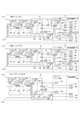
- FIGS. 3 and 4 show the schematic electric circuit configuration from the base unit 2 to the tip of the arm 10 in two separate diagrams.
- FIG. 3 shows a schematic electric circuit configuration from the base unit 2 to the rotating portion 10a of each arm 10
- FIG. 4 shows a schematic electric circuit configuration on the tip side of each arm 10 with respect to the rotating portion 10a.
- the base unit 2 includes a PC board 30, a power switch 31, for example, a light emitting unit 32 using an LED (Light Emitting Diode), a power supply control board 33, a bulb 34, and the above-mentioned elevating mechanism 4.
- a power switch 31 for example, a light emitting unit 32 using an LED (Light Emitting Diode), a power supply control board 33, a bulb 34, and the above-mentioned elevating mechanism 4.
- the PC board 30 is a board on which a microcomputer as a control circuit is mounted, and is provided on the base arm rear 5, the base arm front 6, and each arm 10 for exchanging various data with the above-mentioned operating device. Data communication is performed with each of the electronic boards (base arm rear board 40, base arm front board 50, arm first board 60 to arm sixth board 77).
- the PC board 30 is provided with a communication board 30a for performing data communication with each of these electronic boards.
- the electronic boards arranged in each part of the surgery support device 1 including the communication board 30a are connected to the network by a communication cable (wiring).
- the wiring for connecting the electronic boards to the network in this way is represented by a double line.
- EtherCAT Ethernet for Control Automation Technology
- network communication is performed by a master-slave method in which the communication board 30a is used as a master and each of the other electronic boards is used as a slave.
- a motor for driving a movable portion such as a joint portion for example, a motor 61 in FIG. 3 and a motor 65, 69 in FIG. 4 and the like are contained in the arm 10.
- Sensors for detecting the movement of the moving portion are provided, and the PC board 30 is an electronic board on the arm 10 by data communication by the communication board 30a.
- the PC board 30 can input the detection signal by the above sensor via the electronic board in the arm and output it to the operation device.
- the “signal” output from the PC board 30 means a signal output to the operating device.
- the PC board 30 also controls the power supply control board 33 and the elevating mechanism 4 (up and down mechanism in the vertical direction).
- the power supply control board 33 controls the main power supply of the surgery support device 1 and the operating power supply of each part such as the motor and the sensor described above.
- the PC board 30 monitors the operation of the power switch 31 and controls the on / off of the main power supply according to the operation of the power switch 31. Further, when the main power is turned on, the LED as the light emitting unit 32 is made to emit light so that the main power on state is presented.
- the base arm rear 5 includes a base arm rear substrate 40, pressure sensors 41 and 43, and servo valves 42 and 44.
- a CPU (Central Processing Unit) 40a and an FPGA (Field Programmable Gate Array) 40b are provided in the base arm rear board 40, and an ADC (Analog to Digital Converter) 40c and a DAC (Digital to Analog Converter) 40d are provided. Be done.
- the CPU 40a controls the servo valves 42 and 44 provided on the base arm rear 5 based on the detection signals of the pressure sensors 41 and 43.
- the detection signals of the pressure sensors 41 and 43 are input to the FPGA 40b via the ADC 40c.
- a control signal from the CPU 40a is input to the servo valves 42 and 44 via the FPGA 40b and the DAC 40d.
- the base arm front 6 includes a base arm front board 50, pressure sensors 51, 53, servo valves 52, 54, valves 55, 56, and a switch 57.
- a CPU 50a and an FPGA 50b are provided in the base arm front board 50, and two ADCs 50c and 50c and one DAC50d are provided.
- the CPU 50a controls the servo valves 52, 54 and the valves 55, 56 provided on the base arm front 6 based on the detection signals of the pressure sensors 51, 53. As shown in the figure, the detection signal of the pressure sensor 51 is input to the FPGA 50b via one of the two ADCs 50c, and the pressure sensor 53 detection signal is input to the FPGA 50b via the other ADC 50c.
- control signal from the CPU 50a is input to the servo valves 52 and 54 via the FPGA 50b and the DAC 50d, and the control signal from the CPU 50a is input to the valves 55 and 56 via the FPGA 50b.
- the base arm front board 50 monitors the operation of the switch 57 provided on the base arm front 6.
- Each arm 10 includes an arm first board 60, a motor 61, a sensor 62, and a brake 63, an arm second board 64, a motor 65, a sensor 66, and a brake 67, and an arm third board 68, a motor 69, and a sensor 70.
- the arm first board 60, the motor 61, the sensor 62, and the brake 63 are provided in the rotating portion 10a
- the arm second board 64, the motor 65, the sensor 66, the brake 67, and the arm third board 68 are provided.
- Motor 69, sensor 70, brake 71, arm fourth substrate 72, light emitting portion 75, and arm fifth substrate 76 are gimbal portions on the tip side of the rotating portion 10a (scope gimbal portion in the case of the scope arm 10S). It is provided in the part that is closer to the root side than the base.
- the “holding device portion” in the drawing is the portion closest to the tip of the arm, and represents the formed portion of the surgical instrument holding device 16 described above.
- the gimbal portion (including the scope gimbal portion) is a portion on the arm tip side next to the holding device portion.
- an encoder 73 is also provided at a portion on the tip side of the above-mentioned rotating portion 10a and on the root side of the gimbal portion.
- the encoder 73 is a device such as a rotary encoder that detects a rotational position state.
- the arm sixth substrate 77 and the sensor 78 are provided in the gimbal portion, and the sensor 79, the substrate 80, the switch 81, and the RFID are provided in the holding device portion.
- a communication unit 82, a motor 83, a brake 84, and the above-mentioned manual switch 150 are provided.
- the scope gimbal portion is provided with a sensor 85 and a brake 86
- the holding device portion is provided with a sensor 79, a motor 83, a brake 84, and the above-mentioned manual switch 150.
- the arm first board 60, the arm second board 64, the arm third board 68, the arm fourth board 72, and the arm are extended from the arm root side to the arm tip side.
- Each electronic board is arranged in the order of the fifth board 76 and the arm sixth board 77. Further, in the scope arm 10S, from the arm root side to the arm tip side, each electronic board is in the order of the arm first board 60, the arm second board 64, the arm third board 68, the arm fourth board 72, and the arm fifth board 76. Is placed.
- the motor 61 is a motor for rotationally driving the rotating portion 10a
- the sensor 62 is a sensor for detecting the rotational position state of the rotating portion 10a.
- the brake 63 is an electromagnetic brake (the above-mentioned non-excitation actuated brake) for braking the rotational operation of the arm 10 by the rotating portion 10a.
- the brakes (brake 67, 71, 84, 86) of each part of the arm 10 including the brake 63 are energized by the control of the arm fourth board 72 in response to the on operation of the manual switch 150. ..
- the arm first board 60 controls the drive of the motor 61 based on the drive data acquired from the PC board 30 by network communication. Further, the arm first board 60 transmits the detection information by the sensor 62 to the PC board 30 by network communication.
- the arm second board 64 and the arm third board 68 perform drive control based on drive data acquired from the PC board 30 by network communication for the motor 65 and the motor 69, respectively, and the sensor 66 and the sensor, respectively.
- the detection information by 70 is transmitted to the PC board 30 by network communication.
- the motor 65 is a motor that drives the movable portion formed on the arm 10 that is located on the arm tip side of the rotating portion 10a and on the arm root side of the gimbal portion, and the sensor 66.
- the brake 67 is a sensor for the moving portion, an electromagnetic brake.
- the motor 69 is a motor that drives a movable portion located on the arm tip side of the movable portion driven by the motor 65 and on the arm base side of the gimbal portion, and the sensor 70 and the brake 71 are sensors for the movable portion. It is an electromagnetic brake.
- the arm fourth substrate 72 includes a CPU 72a and an FPGA 72b.
- the detection signal by the encoder 73 is input to the FPGA 72b.
- the encoder 73 detects the rotational position state of the rotating portion arranged at a predetermined position on the arm tip side of the rotating portion 10a and on the arm root side of the gimbal portion.
- the CPU 72a in the first arm 10-1 and the second arm 10-2 performs a process of transmitting the detection signal of the encoder 73 input via the FPGA 72b to the PC board 30 by network communication.
- a detection signal by the sensor 85 in the scope gimbal section and a detection signal by the sensor 79 in the holding device section are input to the FPGA 72b.
- the sensor 85 detects the movement of a predetermined movable portion in the scope gimbal portion
- the sensor 79 detects the movement of the predetermined movable portion in the holding device portion.
- the CPU 72a in the scope arm 10S transmits the detection signals of the sensors 85 and 79 input via the FPGA 72b to the PC board 30 by network communication.
- the CPU 72a of this example has brakes 63, 67, 71, 84 (in the case of the scope arm 10S, the scope gimbal portion) based on an operation signal input from the manual switch 150 provided in the holding device portion via the FPGA 72b. (Including the brake 86) and the light emitting unit 75 are controlled.
- the light emitting unit 75 is controlled to emit light in response to the manual switch 150 being turned on.
- the light emitting unit 75 may be controlled to emit light in response to the manual switch 150 being turned off.
- the arm fifth board 76 controls the drive of the motor 83 in the holding device unit based on the drive data acquired from the PC board 30 by network communication.
- the arm sixth substrate 77 has the CPU 77a and the FPGA 77b, and the CPU 77a includes the sensor 78 in the gimbal portion and the sensor 79 and the substrate 80 in the holding device portion. Performs processing related to the switch 81 and the RFID communication unit 82.
- the sensor 78 detects the movement of a predetermined movable portion in the gimbal portion.
- the sensor 79 detects the movement of a predetermined movable portion in the holding device portion.
- the switch 81 is a switch for detecting the attachment / detachment state of the surgical tool 18 such as forceps with respect to the holding device unit (surgical tool holding device 16), and is turned on / off according to the attachment / detachment of the surgical tool 18.
- the RFID communication unit 82 is a communication unit for detecting the type of the surgical tool 18 attached to the surgical tool holding device 16, and is the RFID tag attached to the surgical tool 18 shown as “ID TAG” in the figure. It is possible to read the stored information.
- the signals from the sensor 79, the substrate 80, and the switch 81 are input to the CPU 77a via the FPGA 77b.
- the sensor 78 and the RFID communication unit 82 are connected to the CPU 77a, and can perform signal communication without going through the FPGA 77b.
- the CPU 77a performs a process of transmitting various detection information acquired from the sensors 78, 79, the switch 81, and the RFID communication unit 82 to the PC board 30 by network communication. Further, the CPU 77a performs a predetermined process according to the information acquired from the substrate 80.
- the wiring connection form for data communication is as follows for the electronic boards arranged in each part in the device as described above. That is, the wiring connection for mutual data communication between the plurality of electronic boards arranged inside the arm 10 and the electronic boards arranged outside the arm 10 is a loop connection. Specifically, in this example, the wiring from the communication board 30a as the master arranged in the base unit 2 passes through the base arm rear board 40, and then the arm first board 60 ⁇ arm in the first arm 10-1.
- one loop is formed as a whole including the plurality of arms 10.
- one master is provided for each arm 10 and a loop connection is performed for each arm 10 starting from the master for each arm 10 can be considered.
- the second embodiment relates to wiring bypass.
- 5 and 6 are diagrams showing a schematic electric circuit configuration in the surgical support device 1 as the second embodiment, and are the same as those in FIGS. 3 and 4, the tips of the base unit 2 to the arm 10.
- the schematic electric circuit configuration up to the part is shown in two figures.
- any one of the electronic boards except the electronic board located most on the base side of the arm and the electronic board located on the tip side of the arm is made more than the electronic board. It is connected by bypassed wiring without going through the electronic board located on the base side of the arm.
- the arm first substrate 60 most arm root side
- the arm sixth substrate 77 most arm.
- the arm third board 68 of the arm fifth board 76 from the arm second board 64 excluding the tip side the electronic board located on the arm root side of the arm third board 68 (here, the arm second board). It is assumed that the bypassed wiring is connected without going through 64).
- the wiring going out from the inside of the arm 10 to the outside of the arm 10 is the arm fifth substrate 76. Since the arm fifth board 76 is located relatively on the tip side in the arm 10, the length of the wiring going out from the inside of the arm 10 to the outside of the arm 10 is relatively long. Will end up. If the wiring length from the inside of the arm 10 to the outside of the arm 10 is long, there is a high possibility that the wiring will be damaged when the arm 10 is attached / detached during maintenance or the like. Further, the attachment / detachment work of the arm 10 becomes difficult, which may lead to a decrease in maintainability.
- the wiring from the arm first board 60 is connected to the arm third board 68 without passing through the arm second board 64, that is, the arm second board 64 is bypassed.
- the wiring from the arm fifth board 76 can be routed through the arm second board 64 that has been bypassed.
- the length of the wiring from the inside of the arm 10 to the outside of the arm 10 can be set to the output wiring length from the arm second board 64 located closer to the arm root side than the arm fifth board 76. It can be shortened as compared with the case of the form.
- the arm second board 64 located second from the arm root side among the electronic boards in the arm 10 is wired bypassed, so that the arm 10 is from the outside to the inside of the arm 10.
- the wiring to the arm 10 can be connected to the arm first substrate 60 located closest to the base of the arm, and the wiring length from the outside of the arm 10 to the inside of the arm 10 can be minimized.
- the wiring from the outside of the arm 10 to the inside of the arm 10 is connected to the electronic board located most on the arm root side in this way, in other words, the wiring from the inside of the arm 10 to the outside of the arm 10 is on the arm root side most.
- the wiring length from the inside of the arm 10 to the outside of the arm 10 can be minimized. Therefore, it is possible to minimize the wiring both from the outside of the arm 10 to the inside of the arm 10 and from the inside of the arm 10 to the outside of the arm 10.
- the wiring from the inside of the arm 10 to the outside of the arm 10 is not the output wiring from the arm sixth board 77 on the most tip side of the arm, and the arm fifth.
- the output wiring is from the board 76, it can be said that this is a configuration in which the arm fifth board 76 is wired bypassed.
- the length of the wiring from the inside of the arm 10 to the outside of the arm 10 is shorter than the case where the output wiring from the arm sixth board 77 on the most tip side of the arm is the wiring from the inside of the arm 10 to the outside of the arm 10. Will be done.
- the electronic board located closest to the tip of the arm is used.
- a configuration may be adopted in which wiring is bypassed by any of the electronic boards except the ones.
- any one of the electronic boards except the electronic board located closest to the arm root side and the electronic board located most to the arm tip side is used as the arm base rather than the electronic board. It may be connected by bypassed wiring without passing through the electronic board located on the side.
- FIGS. 5 and 6 an example in which the arm second board 64 located second from the arm root side is bypassed by wiring has been described, but as shown in FIG. 7, the arm first located closest to the arm root side is described.
- the board 60 may be configured by bypassing the wiring. This makes it possible to connect the output wiring from the arm sixth board 77 located closest to the tip of the arm to the arm first board 60 located closest to the base of the arm, from outside the arm 10 to inside the arm 10. It is possible to minimize the length of wiring to.
- the electronic board for wiring bypass does not have to be common to each arm 10.
- the 1st arm 10-1 bypasses the electronic board on the most root side of the arm (that is, the wiring to the outside of the arm 10 is taken out from the board on the most root side), and the 2nd arm 10-2 is 2 from the base side of the arm.
- At least some of the arms 10 should be different in which position to bypass the wiring, such as bypassing the wiring of the second electronic board (that is, putting the wiring into the arm 10 in the board on the most root side). It can also be.
- the number of electronic boards arranged in the arm 10 is not limited to the number exemplified, and may be at least a plurality.
- the surgical support device (1) as an embodiment includes at least one arm (10) capable of holding a surgical tool, and has a plurality of electronic substrates arranged in the arm.
- the wiring connection for mutual data communication with the electronic board arranged outside the arm is a loop connection.
- a plurality of arms are provided, and the electronic boards in the plurality of arms and the electronic boards arranged outside the arms are loop-connected.
- one loop is formed as a whole including the plurality of arms.
- any one of the electronic boards except the electronic board located most on the base side of the arm and the electronic board located on the tip side of the arm is used. It is connected by bypassed wiring without passing through the electronic board located on the arm base side of the electronic board.
- the length of wiring from the inside of the arm to the outside of the arm can be shortened. This reduces the possibility that the wiring will be damaged when the arm is attached or detached during maintenance or the like.
- the burden on the operator to be careful not to damage the wiring when attaching / detaching the arm can be reduced, which makes it easier to attach / detach the arm and improve the maintainability of the surgical support device. can.
- the second electronic board from the arm root side of the electronic boards in the arm is bypassed by wiring.
- the wiring from the outside of the arm to the inside of the arm can be connected to the electronic board located closest to the base of the arm, and the wiring length from the outside of the arm to the inside of the arm can be minimized.
- the wiring from the outside of the arm to the inside of the arm is connected to the electronic board located most on the arm root side in this way, in other words, the wiring from the inside of the arm to the outside of the arm is located on the electronic board most located on the arm root side.
- the wiring length from the inside of the arm to the outside of the arm can be minimized. Therefore, it is possible to minimize the wiring from the outside of the arm to the inside of the arm and from the inside of the arm to the outside of the arm, and it is possible to enhance the effect of reducing the possibility of wiring damage and the effect of improving maintainability when the arm is attached and detached.
- the electronic board located closest to the base of the arm among the electronic boards in the arm is bypassed by wiring. This makes it possible to connect the wiring from the electronic board located closest to the tip of the arm to the electronic board located closest to the base of the arm, and minimize the length of wiring from the outside of the arm to the inside of the arm. It is planned. Therefore, it is possible to enhance the effect of reducing the possibility of wiring damage and the effect of improving maintainability when attaching and detaching the arm.
- Surgical support device 2 Base unit 3 Base 4 Elevating mechanism 5 Base arm Rear 6 Base arm Front 7 Stage 10 Arm 10S Scope arm 10-1 Arm (No. 1 arm) 10-2 arm (2nd arm) 10a Rotating part 16 Surgical tool holding device 18 Surgical tool 30 PC board 30a Communication board 40 Base arm Rear board 50 Base arm Front board 60 Arm 1st board 64 Arm 2nd board 68 Arm 3rd board 72 Arm 4th board 76 Arm 1st Five boards 77 Arms Sixth board
Landscapes
- Health & Medical Sciences (AREA)
- Surgery (AREA)
- Engineering & Computer Science (AREA)
- Life Sciences & Earth Sciences (AREA)
- Biomedical Technology (AREA)
- Robotics (AREA)
- Nuclear Medicine, Radiotherapy & Molecular Imaging (AREA)
- Heart & Thoracic Surgery (AREA)
- Medical Informatics (AREA)
- Molecular Biology (AREA)
- Animal Behavior & Ethology (AREA)
- General Health & Medical Sciences (AREA)
- Public Health (AREA)
- Veterinary Medicine (AREA)
- Manipulator (AREA)
Priority Applications (2)
| Application Number | Priority Date | Filing Date | Title |
|---|---|---|---|
| PCT/JP2020/033919 WO2022054123A1 (ja) | 2020-09-08 | 2020-09-08 | 手術支援装置 |
| JP2021526295A JPWO2022054123A1 (https=) | 2020-09-08 | 2020-09-08 |
Applications Claiming Priority (1)
| Application Number | Priority Date | Filing Date | Title |
|---|---|---|---|
| PCT/JP2020/033919 WO2022054123A1 (ja) | 2020-09-08 | 2020-09-08 | 手術支援装置 |
Publications (1)
| Publication Number | Publication Date |
|---|---|
| WO2022054123A1 true WO2022054123A1 (ja) | 2022-03-17 |
Family
ID=80631383
Family Applications (1)
| Application Number | Title | Priority Date | Filing Date |
|---|---|---|---|
| PCT/JP2020/033919 Ceased WO2022054123A1 (ja) | 2020-09-08 | 2020-09-08 | 手術支援装置 |
Country Status (2)
| Country | Link |
|---|---|
| JP (1) | JPWO2022054123A1 (https=) |
| WO (1) | WO2022054123A1 (https=) |
Citations (4)
| Publication number | Priority date | Publication date | Assignee | Title |
|---|---|---|---|---|
| JP2004500958A (ja) * | 2000-06-28 | 2004-01-15 | デピュイ インターナショナル リミテッド | 外科手術用器具を位置決めするための装置 |
| JP2006217010A (ja) * | 2005-02-01 | 2006-08-17 | Hitachi Communication Technologies Ltd | 光波長挿入分岐装置およびそれを用いた光ネットワーク装置 |
| JP2010504127A (ja) * | 2006-09-25 | 2010-02-12 | コーニンクレッカ フィリップス エレクトロニクス エヌ ヴィ | ハプティックフィードバックを用いた医用スキャニング方法及び装置 |
| US20190083186A1 (en) * | 2017-09-18 | 2019-03-21 | Verb Surgical Inc. | Robotic Surgical System Having a Communication Network of a Ring Toplogy and Method for Use Therewith |
-
2020
- 2020-09-08 JP JP2021526295A patent/JPWO2022054123A1/ja active Pending
- 2020-09-08 WO PCT/JP2020/033919 patent/WO2022054123A1/ja not_active Ceased
Patent Citations (4)
| Publication number | Priority date | Publication date | Assignee | Title |
|---|---|---|---|---|
| JP2004500958A (ja) * | 2000-06-28 | 2004-01-15 | デピュイ インターナショナル リミテッド | 外科手術用器具を位置決めするための装置 |
| JP2006217010A (ja) * | 2005-02-01 | 2006-08-17 | Hitachi Communication Technologies Ltd | 光波長挿入分岐装置およびそれを用いた光ネットワーク装置 |
| JP2010504127A (ja) * | 2006-09-25 | 2010-02-12 | コーニンクレッカ フィリップス エレクトロニクス エヌ ヴィ | ハプティックフィードバックを用いた医用スキャニング方法及び装置 |
| US20190083186A1 (en) * | 2017-09-18 | 2019-03-21 | Verb Surgical Inc. | Robotic Surgical System Having a Communication Network of a Ring Toplogy and Method for Use Therewith |
Also Published As
| Publication number | Publication date |
|---|---|
| JPWO2022054123A1 (https=) | 2022-03-17 |
Similar Documents
| Publication | Publication Date | Title |
|---|---|---|
| JP6734451B2 (ja) | 複数の遠位に収容されるモータを制御する遠隔電流コントローラを備える医療ロボットシステム | |
| CN101321606B (zh) | 多臂机器人远程外科手术中工具状态通信的指示器 | |
| JP7350085B2 (ja) | 手術用ロボットシステムの構成 | |
| JP6853346B2 (ja) | 長さを維持する外科用器具 | |
| JP6714618B2 (ja) | オフセット計器駆動装置 | |
| US11318603B2 (en) | Delta robot having an input means | |
| WO2006019136A1 (ja) | 電動湾曲制御装置 | |
| WO2000030548B1 (en) | Cooperative minimally invasive telesurgical system | |
| WO2015129644A1 (ja) | 手術用マニピュレータシステム | |
| JP2020533077A (ja) | ロボット外科手術アセンブリのためのエネルギー切断 | |
| KR102675429B1 (ko) | 핸드헬드 구동 유닛을 갖는 외과용 수동 매니퓰레이터 | |
| WO2022054123A1 (ja) | 手術支援装置 | |
| KR20130015441A (ko) | 수술용 로봇 시스템 | |
| EP3871629B1 (en) | Wearable surgical robot arm | |
| JP7848238B2 (ja) | 手術支援システムおよび手術支援ロボット | |
| US12355297B2 (en) | Surgery assistance device with backup power supply | |
| KR20230046569A (ko) | 멀티 툴을 탑재한 웨어러블 수술로봇 | |
| US20240298883A1 (en) | Robotic surgical systems with dexterous endoscope | |
| JP2025186873A (ja) | ロボット手術システム |
Legal Events
| Date | Code | Title | Description |
|---|---|---|---|
| ENP | Entry into the national phase |
Ref document number: 2021526295 Country of ref document: JP Kind code of ref document: A |
|
| 121 | Ep: the epo has been informed by wipo that ep was designated in this application |
Ref document number: 20953191 Country of ref document: EP Kind code of ref document: A1 |
|
| NENP | Non-entry into the national phase |
Ref country code: DE |
|
| 122 | Ep: pct application non-entry in european phase |
Ref document number: 20953191 Country of ref document: EP Kind code of ref document: A1 |