WO2022050184A1 - Performance output toy - Google Patents
Performance output toy Download PDFInfo
- Publication number
- WO2022050184A1 WO2022050184A1 PCT/JP2021/031479 JP2021031479W WO2022050184A1 WO 2022050184 A1 WO2022050184 A1 WO 2022050184A1 JP 2021031479 W JP2021031479 W JP 2021031479W WO 2022050184 A1 WO2022050184 A1 WO 2022050184A1
- Authority
- WO
- WIPO (PCT)
- Prior art keywords
- movement
- toy
- lock
- lock member
- slide
- Prior art date
Links
Images


Classifications
-
- A—HUMAN NECESSITIES
- A63—SPORTS; GAMES; AMUSEMENTS
- A63H—TOYS, e.g. TOPS, DOLLS, HOOPS OR BUILDING BLOCKS
- A63H5/00—Musical or noise- producing devices for additional toy effects other than acoustical
-
- A—HUMAN NECESSITIES
- A63—SPORTS; GAMES; AMUSEMENTS
- A63H—TOYS, e.g. TOPS, DOLLS, HOOPS OR BUILDING BLOCKS
- A63H31/00—Gearing for toys
-
- A—HUMAN NECESSITIES
- A63—SPORTS; GAMES; AMUSEMENTS
- A63H—TOYS, e.g. TOPS, DOLLS, HOOPS OR BUILDING BLOCKS
- A63H33/00—Other toys
-
- A—HUMAN NECESSITIES
- A63—SPORTS; GAMES; AMUSEMENTS
- A63H—TOYS, e.g. TOPS, DOLLS, HOOPS OR BUILDING BLOCKS
- A63H33/00—Other toys
- A63H33/009—Toy swords or similar toy weapons; Toy shields
-
- A—HUMAN NECESSITIES
- A63—SPORTS; GAMES; AMUSEMENTS
- A63H—TOYS, e.g. TOPS, DOLLS, HOOPS OR BUILDING BLOCKS
- A63H33/00—Other toys
- A63H33/22—Optical, colour, or shadow toys
-
- A—HUMAN NECESSITIES
- A63—SPORTS; GAMES; AMUSEMENTS
- A63H—TOYS, e.g. TOPS, DOLLS, HOOPS OR BUILDING BLOCKS
- A63H33/00—Other toys
- A63H33/26—Magnetic or electric toys
Definitions
- the present invention relates to a production output toy.
- Patent Document 1 a production output toy generates a sound or the like based on a predetermined operation (see, for example, Patent Document 1).
- the effect output toy described in Patent Document 1 has a tag reader unit, an operation output unit, a storage unit, a housing unit having a control unit, a lid unit, and the like, and an IC tag separately from the housing unit. It is equipped with another member to be provided, and the like. Then, it is a pronunciation toy configured to be able to pronounce by bringing another member provided with an IC tag close to the tag reader portion of the housing portion and reading the information of the IC tag.
- Patent Document 1 has a configuration in which information on an IC tag is read by bringing two separate members close to each other.
- the effect output toy that starts a predetermined effect by bringing another member close to or attached to the toy or operating a button
- the effect output control of the toy is often performed by electronic control.
- this type of production output toy there is a problem that a specific production is repeatedly performed by a predetermined electronically controlled routine, and the production does not meet the intention of the operator. If you try to solve such a problem by software development, not only will it take a lot of time to develop the software, but there is also a risk of malfunction, so this kind of problem can be solved without relying on electronic control.
- Output toys were wished.
- An object of the present invention is to provide a production output toy with reliable control of production output and high interest.
- the production output toy is A secondary toy body with a starter that activates the production,
- the main toy body to which the sub toy body can be attached and detached is provided.
- the main toy body has an operation unit for operating the activation unit, a link mechanism, and an operation trigger for driving the operation unit via the link mechanism.
- the link mechanism is characterized in that it includes a lock mechanism that invalidates the operation of the operation unit by the operation trigger at the same time as the first drive of the operation unit by the operation trigger.
- the locking mechanism may include an unlocking member for enabling the operation of the operating unit by the operation trigger.
- the unlocking member may be provided so as to be exposed in the main toy body so that the attachment / detachment of the sub toy body from the main toy body can be detected.
- the link mechanism is An unlocking member that is pushed by the sub-toy body by mounting the sub-toy body and is capable of first movement toward the inside of the main toy body.
- a first lock member that is pressed by the first movement of the unlocking member and is capable of a second movement in a direction orthogonal to the first movement.
- a first member capable of moving the first lock member so as to be movable and moving in a direction orthogonal to the second movement to press the first starting part of the starting parts.
- the unlocking member makes a seventh movement in which the unlocking member moves in the direction opposite to the first movement, and by the seventh movement, the position restriction of the first locking member is released.
- the second lock member may be released from the restraint of the first lock member and returned to the original position by the eighth movement which moves in the direction opposite to the fifth movement.
- the link mechanism is A first slide part that is pressed by the operation trigger and can move in the first slide direction, A first rotating part that engages with the first slide part and can rotate in the first rotation direction by moving in the first slide direction. From the contact position with the first slide part in a state where the first rotating part is moved in the second slide direction in the rotation axis direction of the rotation at the same time as the rotation in the first rotation direction. Lock parts that regulate the position when removed, and A second rotating part that is urged by the first rotating part and can rotate in a second rotating direction opposite to the first rotating direction.
- the rotation of the second rotating part causes the second rotating part to rotate in a third rotation direction substantially orthogonal to the rotating surface of the second rotating part, and the starting portion.
- Including a third rotating part that can be pressed and moved to press The first rotating part moves in the second slide direction together with the first rotation direction by the first slide part, and the lock part is engaged at the final stage of the movement in the second slide direction.
- the position may be restricted to a position where the first rotation by the first slide part cannot be performed.
- the link mechanism is provided with an unlocking part that engages with the lock part and releases the position restriction so that the first rotating part returns to an initial position where it can come into contact with the first slide part. You may do so.
- FIG. 1 It is a perspective view of the 1st Embodiment of the production output toy of this invention. It is a perspective view of the main toy body in the production output toy shown in FIG. It is a perspective view of the auxiliary toy body in the production output toy shown in FIG. 1. It is a bottom view which shows the bottom surface of the auxiliary toy body shown in FIG. It is an exploded perspective view of the link mechanism in the production output toy shown in FIG. 1 when viewed from the front side of the toy. It is an exploded perspective view when the link mechanism shown in FIG. 5 is seen from the back side of a toy. It is an enlarged perspective view of the main part of the lock mechanism in the link mechanism shown in FIG.
- FIG. 12 is an exploded perspective view of the link mechanism of the effect output toy shown in FIG. 12 when viewed from the front side of the toy. It is an exploded perspective view when the link mechanism shown in FIG. 13 is seen from the back side of a toy.
- FIG. 14 is an enlarged perspective view of a main part showing a state before the operation of the lock mechanism in the link mechanism shown in FIG.
- FIG. 15 is an enlarged perspective view of a main part showing a state in which the lock mechanism is operated in the link mechanism shown in FIG.
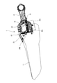
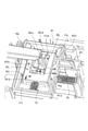
- FIG. 1 is a perspective view showing the entire effect output toy 1 of the first embodiment.
- the effect output toy 1 is roughly classified into a main toy body 10 (hereinafter referred to as “sword 10”) that imitates the shape of a sword and a rectangular shape having identification information. It is configured to include a secondary toy body 30 (hereinafter referred to as “book 30”) that imitates a book.
- the production output toy 1 is a toy that can be produced when the book 30 is attached to and detached from the book mounting portion 23 (see FIG. 2) of the main toy body 10 that imitates a sword used by a fighting hero.
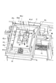
- FIG. 2 is a perspective view of the sword 10 in the effect output toy 1.
- the sword 10 has, for example, a single-edged blade portion 11, a grip portion 12, and a book mounting portion 23.
- the sword 10 includes a detection unit (not shown), a power supply, and a control unit that can detect the information of the book 30 inside. Therefore, when the book 30 is mounted on the book mounting unit 23, the detection unit can read the identification information possessed by the book 30.
- the book mounting portion 23 is provided with a locking piece 24 m that projects toward the inside of the book mounting portion 23 so that the book 30 is mounted sideways.
- Three locking pieces 24m are provided, for example, on the upper side of the sword and on both the front and rear sides.
- the locking piece 24m is configured to be elastically deformable (see FIG. 5) so as to retract in the outward direction of the book when the book 30 is pushed in.
- a book eject button 25 is provided, and by pressing the book eject button 25, the locking piece 24m operates and the book 30 can be ejected.
- the book mounting unit 23 is provided with button operation units (operation units) 46 and 48 that can be operated by an operation trigger 16 via a link mechanism 40 described later on the grip unit 12 side. Further, on the bottom surface of the book mounting portion 23, an unlocking member 40R, which will be described later, which can detect the attachment / detachment of the book 30 is projected.
- the sword 10 is provided with a power switch and an operation trigger 16 as parts to be operated outside the sword 10.
- the operation trigger 16 is provided on the front side of the grip portion 12 so that the grip portion 12 can be operated with a fingertip while being gripped.
- the sound output unit is not particularly limited in its installation, but is arranged in, for example, the widest portion of the blade unit 11. Further, the light output unit can, for example, arrange a light source such as an LED at an appropriate position of the blade portion 11 to produce an effect that the sword 10 shines.
- a light source such as an LED
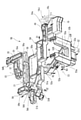
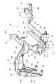
- FIG. 3 is a perspective view of the book 30, and FIG. 4 is a bottom view showing the bottom surface of the book 30.
- the book 30 includes a main body portion 30b fixed to the book mounting portion 23, and an opening / closing portion 30a that can be opened / closed via a hinge portion 30h having an opening / closing shaft 30sf with respect to the main body portion 30b. It is equipped with.
- the opening / closing portion 30a is urged in the rotation direction by a torsion spring 38t arranged between the opening / closing portion 30a and the main body portion 30b.
- it is configured in the shape of a substantially rectangular parallelepiped that imitates the shape of a book that can be automatically opened and spread by operating the second activation button 38f, which will be described later.
- the main body portion 30b is held by engaging the locking piece 24m with the concave groove on the outer periphery thereof. Then, the opening / closing portion 30a can rotate in this holding state (the state shown by the alternate long and short dash line in FIG. 1).
- the opening page can represent, for example, an image of a predetermined character or special information.
- the book 30 has a built-in IC tag in which the identification information unique to the book is recorded.
- two activation buttons are provided on the bottom surface 30bb of the main body portion 30b of the book 30.
- a first activation button (first activation unit) 36b which is a voice button
- a second activation button (second activation unit) 38f is provided on the opening / closing side at a distance.
- the first activation button 36b outputs a voice based on predetermined information in the book.
- the opening / closing portion 30a of the second activation button 38f which is an expansion button, is automatically opened by pressing this button.
- the book 30 can be operated as a single unit to output audio and play, but the main way to play is to attach it to the sword 10 and play as shown in FIG. In that case, after operating the power switch of the sword 10, the book 30 is attached. As a result, the identification information of the book 30 is read by the sword 10.
- the operation trigger 16 when the operation trigger 16 is operated, the first activation button 36b and the second activation button 38f are pressed by the button operation units 46 and 48 in the book 30. As a result, the first audio output is output from the book 30 at the same time as the opening / closing portion 30a rotates. After that, by operating the operation trigger 16, a voice output different from the first voice output, and further, a light emission effect can be performed by the main toy body 10.
- the operation trigger 16 outputs the voice of the book 30 and rotates the opening / closing portion 30a.
- the book 30 is configured by a link mechanism described later so that the book 30 cannot be operated by the link mechanism 4 described later.
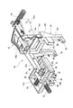
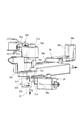
- FIG. 5 is an exploded perspective view of the link mechanism 40 of the effect output toy 1 when viewed from the front side of the toy
- FIG. 6 is an exploded perspective view of the link mechanism 40 when viewed from the back side of the toy
- FIG. 7 is an enlarged perspective view of a main part of the lock mechanism.
- the front-back direction of the toy means the longitudinal direction of the main toy body 10
- the left-right direction of the toy is the direction orthogonal to the longitudinal direction
- the blade portion 11 of the main toy body 10. Refers to the height direction (width direction) of.
- the toy thickness direction is a direction orthogonal to the left-right direction and refers to the thickness direction of the main toy body 10.
- the toy tip direction or the toy tip side means the direction toward the tip of the blade portion 11 of the main toy body 10 or the tip side
- the toy rear end direction or the toy rear end side is opposite to the toy tip direction. It shall refer to the direction or the opposite side.
- the front side of the toy means the side on which the book 30 is mounted, and the side opposite to the back side of the toy.
- the link mechanism 40 has a second member 42 that moves by engaging with the operation trigger 16, a second lock member 42L that moves by engaging with the second member 42, and a second member.
- the first lock member 41L that engages with the two lock member 42L to lock the movement of the second lock member 42L, the first member 41 in which the first lock member 41L is incorporated, the first lock member 41L, and the second lock member 41L. It includes a lock release member 40R that releases the lock state by the lock member 42L.
- a part of the operation trigger 16 is exposed from the grip portion 12, and is provided so that the operation trigger 16 can be rotated around the trigger rotation shaft 16CL. Further, a trigger arm 16a extending from the trigger rotation shaft 16CL in the width direction of the toy body is provided. The tip 16e of the trigger arm 16a is engaged with the second member 42.
- the operation trigger 16 is provided with a coil spring P4 on the back side thereof, and is urged in a direction opposite to the operation direction (pushing direction). Further, a rubber contact switch 10si is provided on the back surface side of the operation trigger 16. Therefore, the rubber contact switch 10si can be switched by the pushing operation of the operation trigger 16 to perform various effects.
- the second member 42 includes a first pressing arm 42a extending in the toy tip direction from a portion (base) close to the trigger rotation shaft 16CL, a base 42b extending in the toy left-right direction from the base of the first pressing arm 42a, and a base 42b.
- a second pressing arm 42c extending from one end side in the toy thickness direction and a button operating portion 48 protruding toward the toy tip direction at the tip of the second pressing arm 42c are provided.
- the second member 42 is provided so as to be slidable in the front-rear direction of the toy. Therefore, by being connected to the operation trigger 16, the movement toward the tip of the toy by the pushing operation of the operation trigger 16, that is, the third movement M3 according to the present embodiment is possible.
- the button operation unit 48 presses the second activation button 38f among the activation buttons. Further, when the pushing of the operation trigger 16 is stopped, the coil spring P4 returns to the rear end direction of the toy in conjunction with the rotation of the operation trigger 16.
- the second lock member 42L is a relatively small block-shaped member, and has an inclined surface 42Le (see FIG. 7) that engages with the first pressing arm 42a of the second member 42 on one end side.
- the second lock member 42L penetrates the first member 41 and the first lock member 41L in the toy thickness direction, and is provided so as to be slidable in the toy thickness direction. Further, the other end side of the second lock member 42L is urged toward the back side of the toy by a coil spring P1 (see FIG. 5).
- the second lock member 42L moves in the front direction of the toy and moves in the same direction as the third movement M3.
- the second lock member 42L is configured so that the side surface on the tip end side of the toy can come into contact with the first lock member 41L.
- the first lock member 41L and the first member 41 are made to perform the fourth movement M4 according to the present embodiment while performing the fifth movement M5 (movement in the front direction of the toy) referred to in the present embodiment. Can be done.
- the first member 41 has a rectangular body body 41a, a tip protrusion 41t extending from the body body 41a toward the tip of the toy, and extending from the body body 41a toward the rear end of the toy and then toward the front side of the toy. It includes an extending leg portion 41c and a button operating portion 46 projecting toward the tip of the toy at the tip of the leg portion 41c.
- the main body body portion 41a has a first lock member 41L inside so as to be movable in the left-right direction of the toy.
- the body portion 41a of the main body is formed with a groove portion 41g (see FIGS. 7 and 8) along the left-right direction of the toy.
- the first lock member 41L is fitted in the groove portion 41g and is held so as to be slidable.
- the first member 41 is held so as to be slidable in the front-rear direction of the toy.
- the body portion 41a of the main body is urged toward the rear end of the toy by the coil spring P3.
- the first member 41 is pressed by the second member via the first lock member 41L and the second lock member 42L, so that the fourth movement M4 referred to in the present embodiment presses the first activation button 36b. It is possible, and when the pressure is released, it moves toward the rear end of the toy.
- the first lock member 41L has a substantially rectangular shape as a whole and has a rectangular opening 41Lh.
- the second lock member 42L described above penetrates the opening 41Lh.
- slide protrusions 41Lb project on both sides in the front-rear direction of the toy, and the slide protrusions 41Lb are fitted into the groove portion 41g of the first member 41 (see FIG. 8). Therefore, the first lock member 41L is attached so as to be slidable in the left-right direction of the toy on the slide surface 41s of the first member 41.
- the first lock member 41L is urged to one side in the left-right direction of the toy by a coil spring P2 between the first lock member 41L and the main body body portion 41a (see FIGS. 6 and 7). Then, by being pressed by the movement of the lock release member 40R, the second movement M2 referred to in the present embodiment is performed against the urging force.
- the lock release member 40R is configured in a block shape, and one end side of the toy front side protrudes from the bottom surface of the book mounting portion 23 (see FIG. 2) and is provided so as to be movable in the toy thickness direction.
- the lock release member 40R is provided with a lock inclined surface 40Re (see FIG. 9) at the other end on the back surface side of the toy.
- the lock inclined surface 40Re can be engaged with one end edge of the opening 41Lh of the first lock member 41L. Therefore, the unlocking member 40R is pushed by the attachment of the book 30 and moves toward the back surface of the toy. As a result, the lock inclined surface 40Re presses the first lock member 41L, and the first movement M1 of the first lock member 41L according to the present embodiment is executed against the urging force of the coil spring P2.
- FIG. 8 is a perspective view showing a state before the operation of the link mechanism 40.
- FIG. 9 is a perspective view showing an initial state of operation of the link mechanism 40.
- FIG. 10 is a perspective view showing a state of the middle stage of operation of the link mechanism 40.
- FIG. 11 is a perspective view showing a state in which the lock mechanism is operated at the final stage of operation of the link mechanism 40.
- the first pressing arm 42a of the second member 42 has the tip inclined surface 42ae at the tip thereof of the second lock member 42L. It is in a state of facing the inclined surface 42Le. Further, other components of the link mechanism 40 are also urged by each coil spring to be positioned at a predetermined position.
- the first movement M1 in which the outer surface of the book 30 pushes the unlocking member 40R into the inside of the toy is executed.
- the first lock member 41L performs the second movement M2 in the first member 41 along the left-right direction of the toy against the urging force of the coil spring P2.
- the protruding edge portion 41Ld provided at the edge portion of the opening 41Lh enters the toy front side (lower side in FIG. 8) of the step portion 42Ld of the second lock member 42L. More specifically with reference to FIG.
- the second movement M2 causes the protruding edge portion 41Ld of the first lock member 41L to enter the recessed portion 42Lk of the second lock member 42L.
- the wall surface 42Lt of the recessed portion 42Lk and the edge portion 41Le of the protruding edge portion 41Ld are in a facing state.
- the second member 42 executes the third movement M3.
- the second activation button 38f is pressed by the third movement M3, and the opening / closing portion 30a of the book 30 is opened.
- the first pressing arm 42a moves toward the tip of the toy while the tip inclined surface 42ae pushes the inclined surface 42Le.
- the first member 41 moves toward the tip of the toy against the urging force of the coil spring P3, and the fourth movement M4 is executed.
- the fourth movement M4 the first activation button 36b is pressed, and the effect by the voice output of the book 30 is executed.
- the engagement position between the second lock member 42L and the first lock member 41L is displaced as shown in FIG. This is because the second lock member 42L is pushed by the first pressing arm 42a, and the contact between the tip inclined surface 42ae and the inclined surface 42Le causes the fifth movement M5 toward the toy surface side (see FIG. 10). Is executed.
- the step portion 42Ld of the second lock member 42L moves so as to get over the protruding edge portion 41Ld of the first lock member 41L, and the step portion 42Ld is the toy front side of the protruding edge portion 41Ld (in FIG. 11). It enters the lower side) and is locked (restrained).
- the unlocking member 40R is pushed out toward the front side of the toy by the urging force of the coil spring P1, and the seventh movement M7 is executed.
- the seventh movement M7 disengages the unlocking member 40R from the first locking member 41L.
- the first lock member 41L is pushed back to its original position by the urging force of the coil spring P2, and the restraint of the second lock member 42L is released.
- the second lock member 42L is pushed back to the back surface side of the toy, and the eighth movement M8 is executed to return to the original position.
- the effect of the book 30 is not unnecessarily repeated, and it is possible to avoid a decrease in interest due to a useless effect that is different from the user's intention, and the operation can be performed.
- the link mechanism 40 is provided with the lock release member 40R for unlocking the lock mechanism that invalidates the operation of the operation trigger 16, so that the lock function is released. It can be undone.
- the lock release member 40R since the lock release member 40R is exposed on the book mounting portion 23, the attachment / detachment of the book 30 is detected, and for example, the lock mechanism is activated by the release operation of the book 30. You can move it. As a result, the unlocking member 40R can be used as an unlocking mechanism linked to the removal of the book 30.
- the link mechanism 40 can operate both activation buttons 36b and 38f by the first operation of the operation trigger 16, but cannot operate the buttons by the second and subsequent operations of the operation trigger 16. ..
- the lock release member 40R can be released from the locked state and returned to the initial state by moving the lock release member 40R based on the removal operation of the book 30.
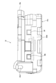
- FIG. 12 is a perspective view showing the main toy body 10 of the second embodiment.
- the main toy body 10 of the present embodiment is configured to include a book mounting portion 23 for mounting the book 30 in an upright position.
- the opening / closing portion 30a of the book 30 is opened at the same time as the voice output by the book 30 by the operation of the first operation trigger 16 as in the first embodiment.
- the opening / closing portion 30a is opened toward the front side of the toy.
- the button operation units 46 and 48 are operated by the link mechanism 50 described later.
- the book 30 is configured not to operate in the second and subsequent operations of the operation trigger 16.
- the blade portion 11 of the main toy body 10 is in a direction orthogonal to the longitudinal direction of the main toy body 10 in the front-rear direction of the toy and the longitudinal direction of the toy left-right direction.
- the height direction (width direction) and the toy thickness direction are the directions orthogonal to the left-right direction and refer to the thickness direction of the main toy body 10.
- the toy tip direction or the toy tip side means the direction toward the tip of the blade portion 11 of the main toy body 10 or the tip side, and the toy rear end direction or the toy rear end side is the direction opposite to the toy tip direction. Alternatively, it shall refer to the other side.
- the front side of the toy means the side on which the book 30 is mounted, and the side opposite to the back side of the toy.
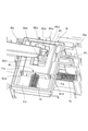
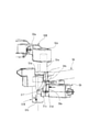
- FIG. 13 is an exploded perspective view of the link mechanism 50 in the main toy body 10 of the present embodiment when viewed from the front side of the toy.
- FIG. 14 is an exploded perspective view of the link mechanism 50 when viewed from the back side of the toy.
- the link mechanism 50 engages with the first slide part 54 provided so as to be slidable in the front-rear direction of the toy by engaging with the operation trigger 16, and is predetermined by engaging with the first slide part 54.
- the first rotating part 51R that can rotate in a direction and the first rotating part 51R can be rotated in a predetermined direction by engaging with the lock part 59 that can regulate the position and the first rotating part 51R. It includes a second rotating part 52R and a third rotating part 53R that engages with the second rotating part 52R and can rotate in a predetermined direction.
- a part of the operation trigger 16 is exposed from the grip portion 12 and is provided so as to be slidable in the left-right direction of the toy. Further, it is urged in a predetermined direction by an urging member (not shown). Further, the operation trigger 16 is urged in a direction opposite to the operation direction (pushing direction). This urging may be configured such that the operation trigger 16 itself is directly urged by a spring or the like, but may be urging using, for example, the urging force of the first slide part 54. Further, a rubber contact switch 10si is provided diagonally laterally on the back surface side of the operation trigger 16. The rubber contact switch 10si can be switched by the pushing operation of the operation trigger 16 to perform various effects.
- the first slide part 54 includes a wide body portion 54a, a first engaging end 54t extending from the body portion 54a toward the tip of the toy, and a second engaging end 54e extending from the body portion 54a toward the rear end of the toy. I have.
- the first engaging end 54t is provided with a first inclined surface 54c that can be engaged with the first rotating part 51R.
- the second engaging end 54e is provided with a second inclined surface 54s that can be engaged with the operation trigger 16.
- the first slide part 54 is urged toward the tip of the toy by the urging member.
- the second inclined surface 54s is pressed by the trigger inclined surface 16s by the pushing operation of the operation trigger 16 (slide movement in the left-right direction of the toy).
- the first slide part 54 moves in the first slide direction S1 in the present embodiment toward the rear end of the toy.
- the first rotating part 51R has a rotating shaft portion 51b, an engaging convex portion 51f that engages with the first slide part 54, and a first extending from the rotating shaft portion 51b toward the rear end of the toy.
- An arm portion 51a and an engaging shaft portion 51e extending in the thickness direction of the toy are provided at the tip end portion of the first arm portion 51a.
- the rotation shaft portion 51b extending in the thickness direction of the toy is rotatably provided around the first rotation axis C1. Further, in the first rotating part 51R, the rotating shaft portion 51b is provided so as to be slidable in the toy thickness direction along the first rotating axis C1, and is urged toward the back surface of the toy.
- the engaging convex portion 51f is provided with a third inclined surface 51c (see FIG. 16) formed on an inclined surface facing the first inclined surface 54c of the first slide part 54. Further, in the engaging convex portion 51f, the toy front side (lower side in FIG. 14) of the third inclined surface 51c protrudes in the radial direction of the rotating shaft portion 51b from the portion where the third inclined surface 51c is formed.
- the locking projection 51d is formed.
- the first rotating part 51R has the first rotating direction R1 referred to in the present embodiment as the first slide part 54 moves due to the engagement between the third inclined surface 51c and the first inclined surface 54c. And move toward the toy surface side in the second slide direction S2.
- the second rotating part 52R has a second arm portion 52a that can rotate around the second rotating axis C2 extending in the thickness direction of the toy, and the same rotating surface with respect to the second arm portion 52a from the middle of the second arm portion 52a. It is provided with a third arm portion 52b that intersects and extends above.
- the second arm portion 52a is provided with a long hole 52e at its tip, and is engaged with the engaging shaft portion 51e of the first rotating part 51R. Therefore, it is urged by the movement of the first rotation part 51R to rotate in the second rotation direction R2 in the present embodiment in the direction opposite to the first rotation direction R1. Further, the tip of the third arm portion 52b is provided with a U-shaped engaging portion 52t having a U-shaped cross section that opens toward the front side of the toy. Further, the second rotating part 52R is urged in a predetermined direction (clockwise direction in FIG. 13 and counterclockwise direction in FIG. 14).
- the third rotating part 53R has a U-shaped body portion 53a that extends in the toy thickness direction and is rotatable about the third rotation axis C3 along the toy front-rear direction, and a toy on one end side of the U-shaped body portion 53a. It includes a pair of button operating portions 46, 48 projecting along the left-right direction, and an engaging end portion 53e provided on the side opposite to the button operating portions 46, 48 (the back side of the toy).
- the button operation units 46 and 48 operate the first activation button 36b and the second activation button 38f of the book 30.
- the engaging end portion 53e is engaged with the U-shaped engaging portion 52t of the third arm portion 52b. Therefore, the third rotating part 53R rotates in the third rotation direction R3 according to the present embodiment, which is substantially orthogonal to the rotating surface of the second rotating part 52R due to the rotation of the third arm portion 52b. do.
- FIG. 15 is an enlarged perspective view of a main part showing a state before the operation of the link mechanism 50.
- FIG. 16 is an enlarged perspective view of a main part showing a state in which the lock mechanism is operated.
- the third inclined surface 51c is pushed by the first inclined surface 54c and rotated in the first rotation direction R1.
- the second rotating part 52R is rotated in the second rotation direction R2 in conjunction with the first rotation direction R1.
- the third rotating part 53R is rotated in the third rotation direction R3 in conjunction with the second rotation direction R2.
- the third inclined surface 51c is pushed at the same time as the rotation of the first rotation direction R1 to the second slide direction S2 which is the toy front side direction.
- the locking projection 51d moves to the front side of the toy from the tip 59e of the lock part 59.
- the tip 59e of the lock part 59 engages with the step portion of the locking projection 51d.
- the tip 59e engages with the step portion of the locking protrusion 51d by moving the locking protrusion 51d in the axial direction.
- the first rotating part 51R is restrained to a position closer to the front side of the toy.
- the book 30 cannot be operated. That is, the first slide part 54 moves in the front-rear direction of the toy by the operation of the operation trigger 16, but it is not possible to give an urging force to the first rotating part 51R only by sliding and moving above the engaging convex portion 51f. .. Further, when the first rotating part 51R is restrained, the urging by the first slide part 54 is released, and the first rotating part 51R, the second rotating part 52R, and the third rotating part 53R are originally. Rotate in the direction of returning to the position of. Therefore, in this state, the button operation units 46 and 48 do not move, and the book 30 cannot be operated.
- the locked state can be released by using the unlocked part 50R.
- a part of the unlocking part 50R is provided so as to project from the main body of the main toy body 10 (see FIG. 12), and the unlocking part 50R can be unlocked by pushing the portion.
- the unlocking part 50R will be described by returning to FIG.
- the lock release part 50R is, for example, abutting with a rod-shaped connecting rod 56 in which one end side 56t supports the lock part 59 and rotates about the fourth rotation axis C4, and one end abutting with the other end side 56e of the connecting rod 56.
- the operation portion 55 whose side is exposed to the outside of the main toy body 10 and the support rod 57 which is rotatable around the fifth rotation axis 5C on one end side and whose other end side pivotally supports the operation portion 55 are provided.
- the lock release part 50R separates the lock part 59 from the first rotation part 51R against the urging force.
- the locking projection 51d is released from the locking projection 51d by the tip 59e of the lock part 59.
- the first rotating part 51R moves toward the back side of the toy and returns to a state in which it can engage with the first slide part 54.
- the effect output toy 1 of the present embodiment can exert the same effect as that of the first embodiment.
- the link mechanism 50 operates the first start button 36b and the second start button 38f by the first operation of the operation trigger 16, and also operates the second slide direction of the first rotation part 51R.
- the movement to S2 causes the first rotation part 51R to be in a free state in the rotation direction.
- the first rotating part 51R does not move in the second and subsequent operations of the operation trigger 16, and the start button cannot be operated.
- the lock state of the operation of the book 30 by the operation trigger 16 can be arbitrarily released without interlocking with the attachment / detachment of the book 30.
- the unlocking part 50R is configured to operate via the connecting rod 56. Therefore, for example, the unlocking operation amount (operating distance) of the operation unit 55 and the lock part 59 The amount of movement can be adjusted as appropriate.
- the present invention can be appropriately modified within the scope of the technical idea.
- the shape of the link element in the link mechanisms 40 and 50 can be appropriately changed.
Abstract
[Problem] To provide a performance output toy that is highly entertaining with excellent accuracy in performance control. [Solution] A performance output toy 1 comprises: a sub-toy body 30 provided with start buttons 36b, 38f for starting performance; and a main toy body 10 to/from which the sub-toy body 30 can be attached/detached, wherein the main toy body 10 is provided with button operation units 46, 48 for operating the start buttons 36b, 38f, linking mechanisms 40, 50, and an action trigger 16 for driving the button operation units 46, 48 via the linking mechanisms 40, 50, and the linking mechanisms 40, 50 are provided with a locking mechanism for disabling action of the button operation units 46, 48 by the action trigger 16, simultaneously with driving of the button operation units 46, 48 for the first time by the action trigger 16.
Description
本発明は、演出出力玩具に関する。
The present invention relates to a production output toy.
従来、演出出力玩具には所定の操作に基づいて音等を発生するものが知られている(例えば特許文献1参照)。特許文献1に記載された演出出力玩具は、タグリーダ部と、動作出力部と、記憶部と、制御部と蓋部等を備える筐体部と、この筐体部とは別体でICタグを備える別部材と、等を備える。そして、筐体部のタグリーダ部に対してICタグを備える別部材を近づけてICタグの情報を読み込むことで発音可能に構成された発音玩具である。
Conventionally, it is known that a production output toy generates a sound or the like based on a predetermined operation (see, for example, Patent Document 1). The effect output toy described in Patent Document 1 has a tag reader unit, an operation output unit, a storage unit, a housing unit having a control unit, a lid unit, and the like, and an IC tag separately from the housing unit. It is equipped with another member to be provided, and the like. Then, it is a pronunciation toy configured to be able to pronounce by bringing another member provided with an IC tag close to the tag reader portion of the housing portion and reading the information of the IC tag.
特許文献1においては、二つの別部材を接近させることでICタグの情報を読み取る構成である。このように別部材を近づけたり装着したりボタン操作をして所定の演出を開始する演出出力玩具においては、玩具の演出出力制御は、多くの場合、電子制御にて行われる。しかしながら、この種の演出出力玩具では、特定の演出が、所定電子制御のルーティンで繰り返し行われ、操作者の意に沿わない演出がされてしまうという問題があった。このような問題をソフト開発で解決しようとすると、ソフト開発に多くの時間を要するだけでなく、誤動作のリスクも残されため、この種の課題を電子制御に頼らず解決できる興趣性の高い演出出力玩具が切望されていた。
Patent Document 1 has a configuration in which information on an IC tag is read by bringing two separate members close to each other. In the effect output toy that starts a predetermined effect by bringing another member close to or attached to the toy or operating a button, the effect output control of the toy is often performed by electronic control. However, in this type of production output toy, there is a problem that a specific production is repeatedly performed by a predetermined electronically controlled routine, and the production does not meet the intention of the operator. If you try to solve such a problem by software development, not only will it take a lot of time to develop the software, but there is also a risk of malfunction, so this kind of problem can be solved without relying on electronic control. Output toys were coveted.
本発明は、演出出力の制御が確実で興趣性の高い演出出力玩具を提供することを目的とする。
An object of the present invention is to provide a production output toy with reliable control of production output and high interest.
本発明に係る演出出力玩具は、
演出を起動する起動部を備える副玩具体と、
前記副玩具体の着脱が可能な主玩具体と、を備え、
前記主玩具体は、前記起動部を動作させる動作部と、リンク機構と、前記リンク機構を介して前記動作部を駆動する操作トリガーと、を有し、
前記リンク機構は、前記操作トリガーによる一回目の前記動作部の駆動と同時に、前記操作トリガーによる前記動作部の操作を無効とするロック機構を備えている、ことを特徴としている。 The production output toy according to the present invention is
A secondary toy body with a starter that activates the production,
The main toy body to which the sub toy body can be attached and detached is provided.
The main toy body has an operation unit for operating the activation unit, a link mechanism, and an operation trigger for driving the operation unit via the link mechanism.
The link mechanism is characterized in that it includes a lock mechanism that invalidates the operation of the operation unit by the operation trigger at the same time as the first drive of the operation unit by the operation trigger.
また、本発明に係る演出出力玩具においては、
前記ロック機構は、前記操作トリガーによる前記動作部の操作を有効化するためのロック解除部材を含む、ようにしてもよい。 Further, in the production output toy according to the present invention,
The locking mechanism may include an unlocking member for enabling the operation of the operating unit by the operation trigger.
前記ロック機構は、前記操作トリガーによる前記動作部の操作を有効化するためのロック解除部材を含む、ようにしてもよい。 Further, in the production output toy according to the present invention,
The locking mechanism may include an unlocking member for enabling the operation of the operating unit by the operation trigger.
また、本発明に係る演出出力玩具においては、
前記ロック解除部材は、前記主玩具体において露出して設けられ、前記副玩具体の前記主玩具体からの着脱を検出可能である、ようにしてもよい。 Further, in the production output toy according to the present invention,
The unlocking member may be provided so as to be exposed in the main toy body so that the attachment / detachment of the sub toy body from the main toy body can be detected.
また、本発明に係る演出出力玩具においては、
前記リンク機構は、
前記副玩具体の装着により前記副玩具体に押されて前記主玩具体の内部に向う第1の移動が可能なロック解除部材と、
前記ロック解除部材の前記第1の移動により押圧されて前記第1の移動とは直交する方向の第2の移動が可能な第1ロック部材と、
前記第1ロック部材を移動可能に内装し前記第2の移動と同一平面上で直交する方向に移動して前記起動部のうち第1起動部を押圧する第4の移動が可能な第1部材と、
前記操作トリガーに押圧されて前記第4の移動と平行な面上を前記第4の移動と同一方向に移動して前記起動部のうち第2起動部を押圧する第3の移動が可能な第2部材と、
前記第2部材の前記第3の移動により押圧され前記第1ロック部材に接して前記第1ロック部材及び前記第1部材を前記第4の移動をさせつつ、前記第1の移動とは反対方向に移動する第5の移動が可能な第2ロック部材と、を含み、
前記操作トリガーによる前記第2部材の前記第3の移動の完了と略同時に、前記第2ロック部材と前記第1ロック部材との係合位置がずれ前記第2ロック部材が前記第2部材との係合位置から外れて前記第1ロック部材に拘束され、前記拘束と同時に前記第1ロック部材及び前記第1部材が前記第4の移動とは逆方向に戻る第6の移動が誘発される、ようにしてもよい。 Further, in the production output toy according to the present invention,
The link mechanism is
An unlocking member that is pushed by the sub-toy body by mounting the sub-toy body and is capable of first movement toward the inside of the main toy body.
A first lock member that is pressed by the first movement of the unlocking member and is capable of a second movement in a direction orthogonal to the first movement.
A first member capable of moving the first lock member so as to be movable and moving in a direction orthogonal to the second movement to press the first starting part of the starting parts. When,
A third movement capable of being pressed by the operation trigger to move on a plane parallel to the fourth movement in the same direction as the fourth movement and pressing the second starting part of the starting parts. 2 members and
Pressed by the third movement of the second member and in contact with the first lock member to move the first lock member and the first member in the fourth movement, in the direction opposite to the first movement. Including a fifth movable lock member, which moves to
Approximately at the same time as the completion of the third movement of the second member by the operation trigger, the engagement position between the second lock member and the first lock member is displaced, and the second lock member is attached to the second member. A sixth movement is induced in which the first lock member and the first member return in the direction opposite to the fourth movement at the same time as the first lock member is restrained by being disengaged from the engaging position. You may do so.
また、本発明に係る演出出力玩具においては、
前記第2ロック部材が前記第2部材との係合位置から外れて前記第1ロック部材に拘束された状態において、
前記副玩具体の取外しによって、前記ロック解除部材が前記第1の移動とは逆方向に移動する第7の移動をし、前記第7の移動によって前記第1ロック部材の位置規制が解除され、前記第2ロック部材は、第1ロック部材の前記拘束から解放されて前記第5の移動とは逆方向に移動する第8の移動により元の位置に戻る、ようにしてもよい。 Further, in the production output toy according to the present invention,
In a state where the second lock member is disengaged from the engagement position with the second member and is restrained by the first lock member.
By removing the sub-toy body, the unlocking member makes a seventh movement in which the unlocking member moves in the direction opposite to the first movement, and by the seventh movement, the position restriction of the first locking member is released. The second lock member may be released from the restraint of the first lock member and returned to the original position by the eighth movement which moves in the direction opposite to the fifth movement.
また、本発明に係る演出出力玩具においては、
前記リンク機構は、
前記操作トリガーに押圧されて第1のスライド方向に移動可能な第1スライドパーツと、
前記第1スライドパーツに係合し前記第1のスライド方向の移動により第1の回動方向に回動可能な第1回動パーツと、
前記第1回動パーツを、前記第1の回動方向の回動と同時に当該回動の回動軸線方向の第2のスライド方向に移動した状態で前記第1スライドパーツとの当接位置から外す状態にて位置規制するロックパーツと、
前記第1回動パーツに付勢されて前記第1の回動方向とは逆向きの第2の回動方向に回動可能な第2回動パーツと、
前記第2回動パーツに付勢されて前記第2回動パーツの回動により前記第2回動パーツの回動面とは略直交する第3の回動方向に回動し、前記起動部を押圧する押圧移動が可能な第3回動パーツと、を含み、
前記第1回動パーツは、前記第1スライドパーツによる前記第1の回動方向と共に前記第2のスライド方向に移動し、前記第2のスライド方向に移動の終段において前記ロックパーツが係合し前記第1スライドパーツによる前記第1の回動が不能なる位置に位置規制される、ようにしてもよい。 Further, in the production output toy according to the present invention,
The link mechanism is
A first slide part that is pressed by the operation trigger and can move in the first slide direction,
A first rotating part that engages with the first slide part and can rotate in the first rotation direction by moving in the first slide direction.
From the contact position with the first slide part in a state where the first rotating part is moved in the second slide direction in the rotation axis direction of the rotation at the same time as the rotation in the first rotation direction. Lock parts that regulate the position when removed, and
A second rotating part that is urged by the first rotating part and can rotate in a second rotating direction opposite to the first rotating direction.
Being urged by the second rotating part, the rotation of the second rotating part causes the second rotating part to rotate in a third rotation direction substantially orthogonal to the rotating surface of the second rotating part, and the starting portion. Including a third rotating part that can be pressed and moved to press
The first rotating part moves in the second slide direction together with the first rotation direction by the first slide part, and the lock part is engaged at the final stage of the movement in the second slide direction. However, the position may be restricted to a position where the first rotation by the first slide part cannot be performed.
また、本発明に係る演出出力玩具においては、
前記リンク機構には、前記ロックパーツに係合し、前記第1回動パーツを前記第1スライドパーツとの当接可能な初期位置に復帰するように位置規制を解除するロック解除パーツが設けられている、ようにしてもよい。 Further, in the production output toy according to the present invention,
The link mechanism is provided with an unlocking part that engages with the lock part and releases the position restriction so that the first rotating part returns to an initial position where it can come into contact with the first slide part. You may do so.
本発明によれば、演出制御の正確性に優れ興趣性の高い演出出力玩具を提供することができる。
According to the present invention, it is possible to provide a production output toy with excellent accuracy of production control and high interest.
(第1実施形態)
以下、本発明の第1実施形態の演出出力玩具1について、図1~図11を参照して説明する。
図1は、第1実施形態の演出出力玩具1の全体を示す斜視図である。 (First Embodiment)
Hereinafter, theeffect output toy 1 according to the first embodiment of the present invention will be described with reference to FIGS. 1 to 11.
FIG. 1 is a perspective view showing the entireeffect output toy 1 of the first embodiment.
以下、本発明の第1実施形態の演出出力玩具1について、図1~図11を参照して説明する。
図1は、第1実施形態の演出出力玩具1の全体を示す斜視図である。 (First Embodiment)
Hereinafter, the
FIG. 1 is a perspective view showing the entire
図1に示すように、演出出力玩具1は、その構成を大別すると、剣の形状を模った主玩具体10(以下、「剣10」と云う)と、識別情報を有する矩形状のブックを模った副玩具体30(以下、「ブック30」と云う)と、を含む構成である。演出出力玩具1は、例えば戦うヒーローが使用する剣を模った主玩具体10のブック装着部23(図2参照)にブック30を着脱して遊ぶときの演出が可能な玩具である。
As shown in FIG. 1, the effect output toy 1 is roughly classified into a main toy body 10 (hereinafter referred to as “sword 10”) that imitates the shape of a sword and a rectangular shape having identification information. It is configured to include a secondary toy body 30 (hereinafter referred to as “book 30”) that imitates a book. The production output toy 1 is a toy that can be produced when the book 30 is attached to and detached from the book mounting portion 23 (see FIG. 2) of the main toy body 10 that imitates a sword used by a fighting hero.
図2は、演出出力玩具1における剣10の斜視図である。
図2に示すように、剣10は、例えば、片刃タイプの刃部11と、握り部12と、ブック装着部23と、有した形状である。この剣10は、内部にブック30の情報を、検出可能な不図示の検出部、電源及び制御部を備えている。したがって、ブック30がブック装着部23に装着されたときに、検出部によって、ブック30が持っている識別情報を読み取ることができる。 FIG. 2 is a perspective view of thesword 10 in the effect output toy 1.
As shown in FIG. 2, thesword 10 has, for example, a single-edged blade portion 11, a grip portion 12, and a book mounting portion 23. The sword 10 includes a detection unit (not shown), a power supply, and a control unit that can detect the information of the book 30 inside. Therefore, when the book 30 is mounted on the book mounting unit 23, the detection unit can read the identification information possessed by the book 30.
図2に示すように、剣10は、例えば、片刃タイプの刃部11と、握り部12と、ブック装着部23と、有した形状である。この剣10は、内部にブック30の情報を、検出可能な不図示の検出部、電源及び制御部を備えている。したがって、ブック30がブック装着部23に装着されたときに、検出部によって、ブック30が持っている識別情報を読み取ることができる。 FIG. 2 is a perspective view of the
As shown in FIG. 2, the
ブック装着部23は、ブック30を横向きに装着するように、ブック装着部23の内側に向かって張り出す係止片24mが設けられている。この係止片24mは、例えば、剣上部側及び前後両側の3個設けられている。また、係止片24mは、ブック30を押し込んだ時にブック外側方向に後退するように弾性変形可能(図5参照)に構成されている。また、ブック取り出しボタン25が設けられており、このブック取り出しボタン25を押すことで、係止片24mが動作してブック30の取り出しが行うことができる。
The book mounting portion 23 is provided with a locking piece 24 m that projects toward the inside of the book mounting portion 23 so that the book 30 is mounted sideways. Three locking pieces 24m are provided, for example, on the upper side of the sword and on both the front and rear sides. Further, the locking piece 24m is configured to be elastically deformable (see FIG. 5) so as to retract in the outward direction of the book when the book 30 is pushed in. Further, a book eject button 25 is provided, and by pressing the book eject button 25, the locking piece 24m operates and the book 30 can be ejected.
ブック装着部23には、握り部12側に、操作トリガー16により後述するリンク機構40を介して動作可能なボタン動作部(動作部)46,48が設けられている。また、ブック装着部23の底面には、ブック30の着脱を検出可能な後述するロック解除部材40Rが突出している。
The book mounting unit 23 is provided with button operation units (operation units) 46 and 48 that can be operated by an operation trigger 16 via a link mechanism 40 described later on the grip unit 12 side. Further, on the bottom surface of the book mounting portion 23, an unlocking member 40R, which will be described later, which can detect the attachment / detachment of the book 30 is projected.
剣10は、その外部には、操作する部分として、電源スイッチ及び操作トリガー16が設けられている。操作トリガー16は、握り部12を握った状態のままで指先にて操作可能なように、握り部12の前方側に設けられている。
The sword 10 is provided with a power switch and an operation trigger 16 as parts to be operated outside the sword 10. The operation trigger 16 is provided on the front side of the grip portion 12 so that the grip portion 12 can be operated with a fingertip while being gripped.
音出力部は、その設置については特に制限されるものでないが、例えば、刃部11の最も幅の広い部位に配置されている。また、光出力部は、例えば、刃部11の適所にLED等の光源を配置して剣10が光る演出をすることができる。
The sound output unit is not particularly limited in its installation, but is arranged in, for example, the widest portion of the blade unit 11. Further, the light output unit can, for example, arrange a light source such as an LED at an appropriate position of the blade portion 11 to produce an effect that the sword 10 shines.
図3は、ブック30の斜視図であり、図4は、ブック30の底面を示す底面図である。
図3に示すように、ブック30は、ブック装着部23に固定される本体部30bと、本体部30bに対して開閉軸30sfを有するヒンジ部30hを介して開閉動可能な開閉部30aと、を備えている。この開閉部30aは、本体部30bとの間に配置されたトーションばね38tによって、その回動方向に付勢されている。要するに、後述する第2起動ボタン38fを操作することで、自動的に開く、見開きが可能な本の形を模した略直方体の形状に構成されている。 FIG. 3 is a perspective view of thebook 30, and FIG. 4 is a bottom view showing the bottom surface of the book 30.
As shown in FIG. 3, thebook 30 includes a main body portion 30b fixed to the book mounting portion 23, and an opening / closing portion 30a that can be opened / closed via a hinge portion 30h having an opening / closing shaft 30sf with respect to the main body portion 30b. It is equipped with. The opening / closing portion 30a is urged in the rotation direction by a torsion spring 38t arranged between the opening / closing portion 30a and the main body portion 30b. In short, it is configured in the shape of a substantially rectangular parallelepiped that imitates the shape of a book that can be automatically opened and spread by operating the second activation button 38f, which will be described later.
図3に示すように、ブック30は、ブック装着部23に固定される本体部30bと、本体部30bに対して開閉軸30sfを有するヒンジ部30hを介して開閉動可能な開閉部30aと、を備えている。この開閉部30aは、本体部30bとの間に配置されたトーションばね38tによって、その回動方向に付勢されている。要するに、後述する第2起動ボタン38fを操作することで、自動的に開く、見開きが可能な本の形を模した略直方体の形状に構成されている。 FIG. 3 is a perspective view of the
As shown in FIG. 3, the
また、本体部30bは、その外周の凹溝に係止片24mが係合して保持される。そして、この保持状態で開閉部30aが回動することができる(図1の一点鎖線にて示す状態)。ブック30は、開閉部30aが開いた時には、当然のことながらその開きページが現れる。この開きページには、例えば、所定のキャラクターや特別な情報の画像を表することができる。また、ブック30内には、そのブック固有の識別情報が記録されたICダグが内蔵されている。
Further, the main body portion 30b is held by engaging the locking piece 24m with the concave groove on the outer periphery thereof. Then, the opening / closing portion 30a can rotate in this holding state (the state shown by the alternate long and short dash line in FIG. 1). When the opening / closing portion 30a of the book 30 is opened, the opening page naturally appears. This opening page can represent, for example, an image of a predetermined character or special information. Further, the book 30 has a built-in IC tag in which the identification information unique to the book is recorded.
図4に示すように、ブック30の本体部30bのブック底面30bbには、起動ボタン(起動部)が2個設けられている。例えば、ヒンジ部30hに近い側に、音声ボタンである第1起動ボタン(第1起動部)36bが設けられ、少し離れて開閉側に第2起動ボタン(第2起動部)38fが設けられている。第1起動ボタン36bは、このボタンが押されることで、ブック内の所定の情報に基づいた音声を出力する。また、展開ボタンである第2起動ボタン38fは、このボタンが押されることで、開閉部30aが自動的に開く。
As shown in FIG. 4, two activation buttons (starting portions) are provided on the bottom surface 30bb of the main body portion 30b of the book 30. For example, a first activation button (first activation unit) 36b, which is a voice button, is provided on the side close to the hinge portion 30h, and a second activation button (second activation unit) 38f is provided on the opening / closing side at a distance. There is. When this button is pressed, the first activation button 36b outputs a voice based on predetermined information in the book. Further, the opening / closing portion 30a of the second activation button 38f, which is an expansion button, is automatically opened by pressing this button.
以下、演出出力玩具1の遊び方の一例について簡単に説明する。
ブック30は、単体としても操作して音声出力をして遊ぶことができるが、遊び方のメインは、図1に示すように、剣10に装着して遊ぶ。その場合、剣10の電源スイッチを操作後に、ブック30装着する。これによって、ブック30の識別情報は剣10側に読み取られる。 Hereinafter, an example of how to play theproduction output toy 1 will be briefly described.
Thebook 30 can be operated as a single unit to output audio and play, but the main way to play is to attach it to the sword 10 and play as shown in FIG. In that case, after operating the power switch of the sword 10, the book 30 is attached. As a result, the identification information of the book 30 is read by the sword 10.
ブック30は、単体としても操作して音声出力をして遊ぶことができるが、遊び方のメインは、図1に示すように、剣10に装着して遊ぶ。その場合、剣10の電源スイッチを操作後に、ブック30装着する。これによって、ブック30の識別情報は剣10側に読み取られる。 Hereinafter, an example of how to play the
The
また、操作トリガー16を操作すると、ブック30は、ボタン動作部46,48により第1起動ボタン36b及び第2起動ボタン38fが押される。これによって、開閉部30aが回動するのと同時に、ブック30から最初の音声出力がされる。その後、操作トリガー16を操作することで、最初の音声出力とは異なった音声出力、さらには、発光演出が主玩具体10によって行うことができる。
Further, when the operation trigger 16 is operated, the first activation button 36b and the second activation button 38f are pressed by the button operation units 46 and 48 in the book 30. As a result, the first audio output is output from the book 30 at the same time as the opening / closing portion 30a rotates. After that, by operating the operation trigger 16, a voice output different from the first voice output, and further, a light emission effect can be performed by the main toy body 10.
ここで、操作トリガー16は、最初の操作では、ブック30の音声出力と開閉部30aの回動動作をする。しかし、その後(二回目以降)の操作では、後述するリンク機構4によりブック30を操作することができないよう、後述するリンク機構より構成されている。
Here, in the first operation, the operation trigger 16 outputs the voice of the book 30 and rotates the opening / closing portion 30a. However, in the subsequent operations (second and subsequent times), the book 30 is configured by a link mechanism described later so that the book 30 cannot be operated by the link mechanism 4 described later.
図5は、演出出力玩具1におけるリンク機構40を玩具表側から見た時の分解斜視図であり、図6は、リンク機構40を玩具裏側から見た時の分解斜視図である。また、図7は、ロック機構の要部拡大斜視図である。なお、以下図5~図11を参照した説明において、玩具前後方向とは主玩具体10の長手方向を云い、玩具左右方向とは長手方向とは直交する方向で主玩具体10の刃部11の高さ方向(幅方向)を云う。また、玩具厚み方向とは、左右方向とは直交する方向で主玩具体10の厚み方向を云うものとする。更に、玩具先端方向或いは玩具先端側とは、主玩具体10の刃部11の先端に向かった方向或いは先端側を云い、玩具後端方向或いは玩具後端側とは、玩具先端方向とは反対方向或いは反対側を云うものとする。また、玩具表側とは、ブック30が装着される側を云い、玩具裏側とはその反対側を云う。
FIG. 5 is an exploded perspective view of the link mechanism 40 of the effect output toy 1 when viewed from the front side of the toy, and FIG. 6 is an exploded perspective view of the link mechanism 40 when viewed from the back side of the toy. Further, FIG. 7 is an enlarged perspective view of a main part of the lock mechanism. In the following description with reference to FIGS. 5 to 11, the front-back direction of the toy means the longitudinal direction of the main toy body 10, and the left-right direction of the toy is the direction orthogonal to the longitudinal direction, and the blade portion 11 of the main toy body 10. Refers to the height direction (width direction) of. Further, the toy thickness direction is a direction orthogonal to the left-right direction and refers to the thickness direction of the main toy body 10. Further, the toy tip direction or the toy tip side means the direction toward the tip of the blade portion 11 of the main toy body 10 or the tip side, and the toy rear end direction or the toy rear end side is opposite to the toy tip direction. It shall refer to the direction or the opposite side. Further, the front side of the toy means the side on which the book 30 is mounted, and the side opposite to the back side of the toy.
図5及び図6に示すように、リンク機構40は、操作トリガー16に係合して移動する第2部材42と、第2部材42に係合して移動する第2ロック部材42Lと、第2ロック部材42Lに係合して第2ロック部材42Lの動きを係止する第1ロック部材41Lと、第1ロック部材41Lが内装された第1部材41と、第1ロック部材41L及び第2ロック部材42Lによるロック状態を解除するロック解除部材40Rと、を備えている。
As shown in FIGS. 5 and 6, the link mechanism 40 has a second member 42 that moves by engaging with the operation trigger 16, a second lock member 42L that moves by engaging with the second member 42, and a second member. The first lock member 41L that engages with the two lock member 42L to lock the movement of the second lock member 42L, the first member 41 in which the first lock member 41L is incorporated, the first lock member 41L, and the second lock member 41L. It includes a lock release member 40R that releases the lock state by the lock member 42L.
操作トリガー16は、その一部が握り部12から露出し、トリガー回転軸16CLを中心にして回転操作可能に設けられている。また、トリガー回転軸16CLから玩具本体幅方向に延出されたトリガーアーム16aを備えている。このトリガーアーム16aは、そのアーム先端16eが第2部材42に係合している。
A part of the operation trigger 16 is exposed from the grip portion 12, and is provided so that the operation trigger 16 can be rotated around the trigger rotation shaft 16CL. Further, a trigger arm 16a extending from the trigger rotation shaft 16CL in the width direction of the toy body is provided. The tip 16e of the trigger arm 16a is engaged with the second member 42.
また、操作トリガー16は、その背面側にはコイルばねP4が設けられており、操作方向(押し込み方向)とは、反対方向に付勢されている。また、操作トリガー16の背面側には、ラバーコンタクトスイッチ10siが設けられている。したがって、操作トリガー16の押し込み動作によって、ラバーコンタクトスイッチ10siがスイッチングされて各種の演出を行うことができる。
Further, the operation trigger 16 is provided with a coil spring P4 on the back side thereof, and is urged in a direction opposite to the operation direction (pushing direction). Further, a rubber contact switch 10si is provided on the back surface side of the operation trigger 16. Therefore, the rubber contact switch 10si can be switched by the pushing operation of the operation trigger 16 to perform various effects.
第2部材42は、トリガー回転軸16CLに接近した部位(基部)から玩具先端方向に延びる第一押圧アーム42aと、第一押圧アーム42aの基部から玩具左右方向に延びる基部42bと、基部42bの一端側から玩具厚み方向に延出された第二押圧アーム42cと、第二押圧アーム42cの先端に玩具先端方向に向かって突出したボタン動作部48と、を備えている。
The second member 42 includes a first pressing arm 42a extending in the toy tip direction from a portion (base) close to the trigger rotation shaft 16CL, a base 42b extending in the toy left-right direction from the base of the first pressing arm 42a, and a base 42b. A second pressing arm 42c extending from one end side in the toy thickness direction and a button operating portion 48 protruding toward the toy tip direction at the tip of the second pressing arm 42c are provided.
第2部材42は、玩具前後方向にスライド移動可能に設けられている。したがって、操作トリガー16に連結されていることで、操作トリガー16の押し込み操作によって玩具先端方向に向かう移動、すなわち、本実施形態で云う第3の移動M3が可能である。この第3の移動M3により、後述するように、ボタン動作部48が起動ボタンのうち第2起動ボタン38fを押圧する。また、操作トリガー16の押し込みを止めると、コイルばねP4により操作トリガー16の回転に連動して玩具後端方向に戻る。
The second member 42 is provided so as to be slidable in the front-rear direction of the toy. Therefore, by being connected to the operation trigger 16, the movement toward the tip of the toy by the pushing operation of the operation trigger 16, that is, the third movement M3 according to the present embodiment is possible. By this third movement M3, as will be described later, the button operation unit 48 presses the second activation button 38f among the activation buttons. Further, when the pushing of the operation trigger 16 is stopped, the coil spring P4 returns to the rear end direction of the toy in conjunction with the rotation of the operation trigger 16.
第2ロック部材42Lは、ブロック状の比較的小さな部材で、一端側には、第2部材42の第一押圧アーム42aに係合する傾斜面42Le(図7参照)を有している。第2ロック部材42Lは、第1部材41及び第1ロック部材41Lを玩具厚み方向に貫通し、玩具厚み方向にスライド移動可能に設けられている。また、第2ロック部材42Lは、他端側がコイルばねP1(図5参照)によって玩具裏側にむかって付勢されている。
The second lock member 42L is a relatively small block-shaped member, and has an inclined surface 42Le (see FIG. 7) that engages with the first pressing arm 42a of the second member 42 on one end side. The second lock member 42L penetrates the first member 41 and the first lock member 41L in the toy thickness direction, and is provided so as to be slidable in the toy thickness direction. Further, the other end side of the second lock member 42L is urged toward the back side of the toy by a coil spring P1 (see FIG. 5).
したがって、第2部材42の第3の移動M3により押圧されることで、2方向に移動する。要するに、第2ロック部材42Lは、傾斜面42Leが押されることで、玩具表方向への移動と、第3の移動M3と同方向への移動とが生じる。また、第2ロック部材42Lは、玩具先端側の側面が第1ロック部材41Lに接触可能に構成されている。この結果、本実施形態で云う第5の移動M5(玩具表方向への移動)をしながら、第1ロック部材41L及び第1部材41を、本実施形態で云う第4の移動M4をさせることができる。
Therefore, it moves in two directions by being pressed by the third movement M3 of the second member 42. In short, when the inclined surface 42Le is pushed, the second lock member 42L moves in the front direction of the toy and moves in the same direction as the third movement M3. Further, the second lock member 42L is configured so that the side surface on the tip end side of the toy can come into contact with the first lock member 41L. As a result, the first lock member 41L and the first member 41 are made to perform the fourth movement M4 according to the present embodiment while performing the fifth movement M5 (movement in the front direction of the toy) referred to in the present embodiment. Can be done.
第1部材41は、矩形状の本体胴部41aと、本体胴部41aから玩具先端方向に延びる先端突部41tと、本体胴部41aから玩具後端方向に延びたのちに玩具表側に向かって延びる脚部41cと、脚部41cの先端において玩具先端方向に突出するボタン動作部46と、を備えている。また、本体胴部41aは、第1ロック部材41Lを玩具左右方向に移動可能に内装している。詳細には、本体胴部41aには玩具左右方向に沿った溝部41g(図7及び図8参照)が形成されている。そして、第1ロック部材41Lは、溝部41gに嵌合してスライド移動可能に保持されている。
The first member 41 has a rectangular body body 41a, a tip protrusion 41t extending from the body body 41a toward the tip of the toy, and extending from the body body 41a toward the rear end of the toy and then toward the front side of the toy. It includes an extending leg portion 41c and a button operating portion 46 projecting toward the tip of the toy at the tip of the leg portion 41c. Further, the main body body portion 41a has a first lock member 41L inside so as to be movable in the left-right direction of the toy. Specifically, the body portion 41a of the main body is formed with a groove portion 41g (see FIGS. 7 and 8) along the left-right direction of the toy. The first lock member 41L is fitted in the groove portion 41g and is held so as to be slidable.
また、第1部材41は、玩具前後方向にスライド可能に保持されている。本体胴部41aは、コイルばねP3によって玩具後端方向に付勢されている。そして、第1部材41は、第1ロック部材41L及び第2ロック部材42Lを介し第2部材に押圧されることによって、第1起動ボタン36bを押圧する本実施形態で云う第4の移動M4が可能であり、押圧が解除されると、玩具後端方向に移動する。
Further, the first member 41 is held so as to be slidable in the front-rear direction of the toy. The body portion 41a of the main body is urged toward the rear end of the toy by the coil spring P3. Then, the first member 41 is pressed by the second member via the first lock member 41L and the second lock member 42L, so that the fourth movement M4 referred to in the present embodiment presses the first activation button 36b. It is possible, and when the pressure is released, it moves toward the rear end of the toy.
第1ロック部材41Lは、全体形状が略矩形で、矩形状の開口41Lhを有する。この開口41Lhは、前掲の第2ロック部材42Lが貫通している。また、玩具前後方向の両側には、スライド突起41Lbが突出しており、このスライド突起41Lbが第1部材41の溝部41gに嵌合している(図8参照)。したがって、第1ロック部材41Lは、第1部材41のスライド面41s上を玩具左右方向にスライド移動可能に取り付けられている。
The first lock member 41L has a substantially rectangular shape as a whole and has a rectangular opening 41Lh. The second lock member 42L described above penetrates the opening 41Lh. Further, slide protrusions 41Lb project on both sides in the front-rear direction of the toy, and the slide protrusions 41Lb are fitted into the groove portion 41g of the first member 41 (see FIG. 8). Therefore, the first lock member 41L is attached so as to be slidable in the left-right direction of the toy on the slide surface 41s of the first member 41.
第1ロック部材41Lは、本体胴部41aとの間にコイルばねP2により玩具左右方向の一方側へ付勢されている(図6及び図7参照)。そして、ロック解除部材40Rの移動により押圧されることで、付勢力に抗して本実施形態で云う第2の移動M2をする。
The first lock member 41L is urged to one side in the left-right direction of the toy by a coil spring P2 between the first lock member 41L and the main body body portion 41a (see FIGS. 6 and 7). Then, by being pressed by the movement of the lock release member 40R, the second movement M2 referred to in the present embodiment is performed against the urging force.
ロック解除部材40Rは、ブロック形状に構成され、玩具表側の一端側がブック装着部23の底面から突出(図2参照)し、玩具厚み方向に移動可能に設けられている。ロック解除部材40Rは、その玩具裏面側の他端部には、ロック傾斜面40Re(図9参照)が設けられている。このロック傾斜面40Reは、第1ロック部材41Lの開口41Lhの一端縁に係合可能である。したがって、ロック解除部材40Rは、ブック30の装着により押され玩具裏面方向に移動する。これにより、ロック傾斜面40Reが第1ロック部材41Lを押圧して、コイルばねP2の付勢力に抗して第1ロック部材41Lの本実施形態で云う第1の移動M1が実行される。
The lock release member 40R is configured in a block shape, and one end side of the toy front side protrudes from the bottom surface of the book mounting portion 23 (see FIG. 2) and is provided so as to be movable in the toy thickness direction. The lock release member 40R is provided with a lock inclined surface 40Re (see FIG. 9) at the other end on the back surface side of the toy. The lock inclined surface 40Re can be engaged with one end edge of the opening 41Lh of the first lock member 41L. Therefore, the unlocking member 40R is pushed by the attachment of the book 30 and moves toward the back surface of the toy. As a result, the lock inclined surface 40Re presses the first lock member 41L, and the first movement M1 of the first lock member 41L according to the present embodiment is executed against the urging force of the coil spring P2.
上記のごとく構成されたリンク機構40の動作について、図8~図11を参照して説明する。図8は、リンク機構40動作前の状態を示す斜視図である。図9は、リンク機構40の動作初期の状態を示す斜視図である。図10は、リンク機構40の動作中段の状態を示す斜視図である。図11は、リンク機構40の動作終段においてロック機構が作動した状態を示す斜視図である。
The operation of the link mechanism 40 configured as described above will be described with reference to FIGS. 8 to 11. FIG. 8 is a perspective view showing a state before the operation of the link mechanism 40. FIG. 9 is a perspective view showing an initial state of operation of the link mechanism 40. FIG. 10 is a perspective view showing a state of the middle stage of operation of the link mechanism 40. FIG. 11 is a perspective view showing a state in which the lock mechanism is operated at the final stage of operation of the link mechanism 40.
先ず、ブック30をブック装着部23に装着する前の状態は、図8に示すように、第2部材42の第一押圧アーム42aは、その先端の先端傾斜面42aeが第2ロック部材42Lの傾斜面42Leに対面した状態にある。また、リンク機構40の他の構成要素も、各コイルばねに付勢されて所定の位置に位置している。
First, in the state before the book 30 is mounted on the book mounting portion 23, as shown in FIG. 8, the first pressing arm 42a of the second member 42 has the tip inclined surface 42ae at the tip thereof of the second lock member 42L. It is in a state of facing the inclined surface 42Le. Further, other components of the link mechanism 40 are also urged by each coil spring to be positioned at a predetermined position.
ブック30が装着されると、ブック30の外面が、ロック解除部材40Rを玩具内側に押し込む第1の移動M1が実行される。これにより、図9に示すように、第1ロック部材41LがコイルばねP2の付勢力に抗して第1部材41内を玩具左右方向に沿って第2の移動M2が実行される。これにより、第1ロック部材41Lは、開口41Lhの縁部に設けられた突出縁部41Ldが第2ロック部材42Lの段部42Ldの玩具表側(図8において下側)に入り込む。図7を参照して更に詳しく説明すると、第2の移動M2によって、第1ロック部材41Lは、突出縁部41Ldが第2ロック部材42Lの窪み部42Lk内に進入する。これにより、窪み部42Lkの壁面42Ltと突出縁部41Ldの縁部41Leとが対面状態となる。
When the book 30 is attached, the first movement M1 in which the outer surface of the book 30 pushes the unlocking member 40R into the inside of the toy is executed. As a result, as shown in FIG. 9, the first lock member 41L performs the second movement M2 in the first member 41 along the left-right direction of the toy against the urging force of the coil spring P2. As a result, in the first lock member 41L, the protruding edge portion 41Ld provided at the edge portion of the opening 41Lh enters the toy front side (lower side in FIG. 8) of the step portion 42Ld of the second lock member 42L. More specifically with reference to FIG. 7, the second movement M2 causes the protruding edge portion 41Ld of the first lock member 41L to enter the recessed portion 42Lk of the second lock member 42L. As a result, the wall surface 42Lt of the recessed portion 42Lk and the edge portion 41Le of the protruding edge portion 41Ld are in a facing state.
次に、操作トリガー16を操作することで、図10に示すように、第2部材42によって第3の移動M3が実行される。この第3の移動M3によって第2起動ボタン38fが押され、ブック30の開閉部30aが開かれる。
Next, by operating the operation trigger 16, as shown in FIG. 10, the second member 42 executes the third movement M3. The second activation button 38f is pressed by the third movement M3, and the opening / closing portion 30a of the book 30 is opened.
また、この第3の移動M3によって、第一押圧アーム42aは、先端傾斜面42aeが傾斜面42Leを押しながら玩具先端方向に移動する。これによって、第1部材41は、コイルばねP3の付勢力に抗して玩具先端方向に移動し、第4の移動M4が実行される。この第4の移動M4によって、第1起動ボタン36bが押され、ブック30の音声出力による演出が実行される。
Further, by this third movement M3, the first pressing arm 42a moves toward the tip of the toy while the tip inclined surface 42ae pushes the inclined surface 42Le. As a result, the first member 41 moves toward the tip of the toy against the urging force of the coil spring P3, and the fourth movement M4 is executed. By this fourth movement M4, the first activation button 36b is pressed, and the effect by the voice output of the book 30 is executed.
このように、操作トリガー16による第2部材42の第3の移動M3の完了と略同時に、図11に示すように、第2ロック部材42Lと第1ロック部材41Lとの係合位置がずれる。これは、第2ロック部材42Lは、第一押圧アーム42aに押されることで、先端傾斜面42aeと傾斜面42Leとの当接で玩具表面側に向かって第5の移動M5(図10参照)が実行される。この第5の移動M5によって、第2ロック部材42Lの段部42Ldが第1ロック部材41Lの突出縁部41Ldを乗り越えるように移動し、段部42Ldが突出縁部41Ldの玩具表側(図11中の下側)に入り込んで係止(拘束)される。
As described above, substantially at the same time as the completion of the third movement M3 of the second member 42 by the operation trigger 16, the engagement position between the second lock member 42L and the first lock member 41L is displaced as shown in FIG. This is because the second lock member 42L is pushed by the first pressing arm 42a, and the contact between the tip inclined surface 42ae and the inclined surface 42Le causes the fifth movement M5 toward the toy surface side (see FIG. 10). Is executed. By this fifth movement M5, the step portion 42Ld of the second lock member 42L moves so as to get over the protruding edge portion 41Ld of the first lock member 41L, and the step portion 42Ld is the toy front side of the protruding edge portion 41Ld (in FIG. 11). It enters the lower side) and is locked (restrained).
第2ロック部材42Lが、第2部材42との係合位置から外れて第1ロック部材41Lに拘束された状態となると、第1部材41に対して、第一押圧アーム42aによる押圧がなくなる。これにより、第1部材41は、第4の移動M4とは逆方向に戻る第6の移動M6が実行される。
When the second lock member 42L is disengaged from the engagement position with the second member 42 and is restrained by the first lock member 41L, the first member 41 is not pressed by the first pressing arm 42a. As a result, the first member 41 is executed with the sixth movement M6 returning in the direction opposite to the fourth movement M4.
この状態においては、操作トリガー16を操作しても、第1部材41は動作することはなく、ブック30の音声は出力されない。しかし、操作トリガー16に操作によって、ラバーコンタクトスイッチ10siはスイッチング操作されるので、ブック30の初期の演出以外は行うことができる。
In this state, even if the operation trigger 16 is operated, the first member 41 does not operate and the sound of the book 30 is not output. However, since the rubber contact switch 10si is switched by the operation trigger 16, the rubber contact switch 10si can be operated except for the initial effect of the book 30.
ブック30を主玩具体10から取り外す。これによって、ロック解除部材40Rは、コイルばねP1の付勢力によって玩具表側の方向に押しも出される、第7の移動M7が実行される。この第7の移動M7によって、第1ロック部材41Lに対するロック解除部材40Rの係合が外れる。これによって、第1ロック部材41Lは、コイルばねP2の付勢力によって元の位置に押し戻され、第2ロック部材42Lの拘束を解除する。この結果、第2ロック部材42Lは、玩具裏面側に押し戻され、第8の移動M8が実行されて元の位置に復帰する。
Remove the book 30 from the main toy body 10. As a result, the unlocking member 40R is pushed out toward the front side of the toy by the urging force of the coil spring P1, and the seventh movement M7 is executed. The seventh movement M7 disengages the unlocking member 40R from the first locking member 41L. As a result, the first lock member 41L is pushed back to its original position by the urging force of the coil spring P2, and the restraint of the second lock member 42L is released. As a result, the second lock member 42L is pushed back to the back surface side of the toy, and the eighth movement M8 is executed to return to the original position.
以上述べたように、本実施形態の演出出力玩具1によれば、ブック30による演出を不必要に繰り返すことが無くなり、ユーザーの意図とは異なる無駄な演出による興趣性の低下を回避でき、操作性の良い興趣性の高い玩具を提供できる。
As described above, according to the effect output toy 1 of the present embodiment, the effect of the book 30 is not unnecessarily repeated, and it is possible to avoid a decrease in interest due to a useless effect that is different from the user's intention, and the operation can be performed. We can provide toys with good sexuality and high interest.
また、本実施形態の演出出力玩具1では、リンク機構40が、操作トリガー16の動作を無効にするロック機構のロックを解除するロック解除部材40Rが設けられているので、ロック機能を解除して元に戻すことができる。
Further, in the effect output toy 1 of the present embodiment, the link mechanism 40 is provided with the lock release member 40R for unlocking the lock mechanism that invalidates the operation of the operation trigger 16, so that the lock function is released. It can be undone.
また、本実施形態の演出出力玩具1では、ロック解除部材40Rがブック装着部23に露出して設けられているので、ブック30の着脱を検出し、例えば、ブック30の離脱動作によりロック機構を動かすことができる。この結果、ロック解除部材40Rを、ブック30の取外しと連動するロック解除機構とすることができる。
Further, in the effect output toy 1 of the present embodiment, since the lock release member 40R is exposed on the book mounting portion 23, the attachment / detachment of the book 30 is detected, and for example, the lock mechanism is activated by the release operation of the book 30. You can move it. As a result, the unlocking member 40R can be used as an unlocking mechanism linked to the removal of the book 30.
本実施形態の演出出力玩具1では、リンク機構40は、操作トリガー16の1回目の操作によって両起動ボタン36b,38fが操作できるが、操作トリガー16の2回目以降の操作ではボタン操作が出来ない。
In the effect output toy 1 of the present embodiment, the link mechanism 40 can operate both activation buttons 36b and 38f by the first operation of the operation trigger 16, but cannot operate the buttons by the second and subsequent operations of the operation trigger 16. ..
また、本実施形態の演出出力玩具1では、ブック30の取外し操作に基づくロック解除部材40Rの移動により、リンク機構40はロック状態が解除されて初期状態に戻ることができる。
Further, in the effect output toy 1 of the present embodiment, the lock release member 40R can be released from the locked state and returned to the initial state by moving the lock release member 40R based on the removal operation of the book 30.
(第2実施形態)
以下、本発明の第2実施形態の主玩具体10について、図12~図16を参照して説明する。なお、本実施形態においては、第1実施形態と同様の構成要素については、同じ符号を付して説明を省略する。また、リンク機構50において付勢力を付与するばね部材については記載を省略する。 (Second Embodiment)
Hereinafter, themain toy body 10 of the second embodiment of the present invention will be described with reference to FIGS. 12 to 16. In the present embodiment, the same components as those in the first embodiment are designated by the same reference numerals and the description thereof will be omitted. Further, the description of the spring member that applies the urging force in the link mechanism 50 will be omitted.
以下、本発明の第2実施形態の主玩具体10について、図12~図16を参照して説明する。なお、本実施形態においては、第1実施形態と同様の構成要素については、同じ符号を付して説明を省略する。また、リンク機構50において付勢力を付与するばね部材については記載を省略する。 (Second Embodiment)
Hereinafter, the
図12は、第2実施形態の主玩具体10を示す斜視図である。
本実施形態の主玩具体10においては、ブック30を立て向きに装着するブック装着部23を備える構成である。ブック装着部23に装着されたブック30は、最初の操作トリガー16の操作によって、第1実施形態と同様に、ブック30による音声出力と同時に、ブック30の開閉部30aが開かれる。なお、この場合、開閉部30aは、玩具前方側に向かって開かれる。また、本実施形態においては、後述するリンク機構50によって、ボタン動作部46,48が動作する。操作トリガー16の二回目以降の操作では、ブック30が作動しないように構成されている。 FIG. 12 is a perspective view showing themain toy body 10 of the second embodiment.
Themain toy body 10 of the present embodiment is configured to include a book mounting portion 23 for mounting the book 30 in an upright position. In the book 30 mounted on the book mounting portion 23, the opening / closing portion 30a of the book 30 is opened at the same time as the voice output by the book 30 by the operation of the first operation trigger 16 as in the first embodiment. In this case, the opening / closing portion 30a is opened toward the front side of the toy. Further, in the present embodiment, the button operation units 46 and 48 are operated by the link mechanism 50 described later. The book 30 is configured not to operate in the second and subsequent operations of the operation trigger 16.
本実施形態の主玩具体10においては、ブック30を立て向きに装着するブック装着部23を備える構成である。ブック装着部23に装着されたブック30は、最初の操作トリガー16の操作によって、第1実施形態と同様に、ブック30による音声出力と同時に、ブック30の開閉部30aが開かれる。なお、この場合、開閉部30aは、玩具前方側に向かって開かれる。また、本実施形態においては、後述するリンク機構50によって、ボタン動作部46,48が動作する。操作トリガー16の二回目以降の操作では、ブック30が作動しないように構成されている。 FIG. 12 is a perspective view showing the
The
また、以下の説明においては、第1実施形態と同様に、玩具前後方向とは主玩具体10の長手方向、玩具左右方向とは長手方向とは直交する方向で主玩具体10の刃部11の高さ方向(幅方向)、更に、玩具厚み方向とは、左右方向とは直交する方向で主玩具体10の厚み方向を云うものとする。玩具先端方向或いは玩具先端側とは、主玩具体10の刃部11の先端に向かった方向或いは先端の側を云い、玩具後端方向或いは玩具後端側とは、玩具先端方向とは反対方向或いは反対側を云うものとする。また、玩具表側とは、ブック30が装着される側を云い、玩具裏側とはその反対側を云う。
Further, in the following description, as in the first embodiment, the blade portion 11 of the main toy body 10 is in a direction orthogonal to the longitudinal direction of the main toy body 10 in the front-rear direction of the toy and the longitudinal direction of the toy left-right direction. The height direction (width direction) and the toy thickness direction are the directions orthogonal to the left-right direction and refer to the thickness direction of the main toy body 10. The toy tip direction or the toy tip side means the direction toward the tip of the blade portion 11 of the main toy body 10 or the tip side, and the toy rear end direction or the toy rear end side is the direction opposite to the toy tip direction. Alternatively, it shall refer to the other side. Further, the front side of the toy means the side on which the book 30 is mounted, and the side opposite to the back side of the toy.
図13は、本実施形態の主玩具体10におけるリンク機構50を玩具表側から見た時の分解斜視図である。図14は、リンク機構50を玩具裏側から見た時の分解斜視図である。
FIG. 13 is an exploded perspective view of the link mechanism 50 in the main toy body 10 of the present embodiment when viewed from the front side of the toy. FIG. 14 is an exploded perspective view of the link mechanism 50 when viewed from the back side of the toy.
リンク機構50は、図13及び図14に示すように、操作トリガー16に係合し玩具前後方向にスライド可能に設けられた第1スライドパーツ54と、第1スライドパーツ54に係合して所定方向に回動可能な第1回動パーツ51Rと、第1回動パーツ51Rを、位置規制可能なロックパーツ59と、第1回動パーツ51Rに係合して所定の方向に回動可能な第2回動パーツ52Rと、第2回動パーツ52Rに係合して、所定の方向に回動可能な第3回動パーツ53Rと、を備えている。
As shown in FIGS. 13 and 14, the link mechanism 50 engages with the first slide part 54 provided so as to be slidable in the front-rear direction of the toy by engaging with the operation trigger 16, and is predetermined by engaging with the first slide part 54. The first rotating part 51R that can rotate in a direction and the first rotating part 51R can be rotated in a predetermined direction by engaging with the lock part 59 that can regulate the position and the first rotating part 51R. It includes a second rotating part 52R and a third rotating part 53R that engages with the second rotating part 52R and can rotate in a predetermined direction.
操作トリガー16は、その一部が握り部12から露出し、玩具左右方向にスライド可能に設けられている。また、図示しない付勢部材により所定方向に付勢されている。また、操作トリガー16は、操作方向(押し込み方向)とは、反対方向に付勢されている。この付勢は、操作トリガー16自体が直接バネ等で付勢される構成であっても良いが、例えば第1スライドパーツ54の付勢力を利用した付勢であっても良い。また、操作トリガー16の背面側の斜め横方向には、ラバーコンタクトスイッチ10siが設けられている。このラバーコンタクトスイッチ10siは、操作トリガー16の押し込み動作によって、スイッチングされて各種の演出を行うことができる。
A part of the operation trigger 16 is exposed from the grip portion 12 and is provided so as to be slidable in the left-right direction of the toy. Further, it is urged in a predetermined direction by an urging member (not shown). Further, the operation trigger 16 is urged in a direction opposite to the operation direction (pushing direction). This urging may be configured such that the operation trigger 16 itself is directly urged by a spring or the like, but may be urging using, for example, the urging force of the first slide part 54. Further, a rubber contact switch 10si is provided diagonally laterally on the back surface side of the operation trigger 16. The rubber contact switch 10si can be switched by the pushing operation of the operation trigger 16 to perform various effects.
第1スライドパーツ54は、幅広な胴部54aと、胴部54aから玩具先端方向に延びる第一係合端54tと、胴部54aから玩具後方端方向に延びる第二係合端54eと、を備えている。第一係合端54tには、第1回動パーツ51Rと係合可能な第一傾斜面54cが設けられている。第二係合端54eには、操作トリガー16と係合可能な第二傾斜面54sが設けられている。第1スライドパーツ54は、付勢部材によって玩具先端方向に付勢されている。
The first slide part 54 includes a wide body portion 54a, a first engaging end 54t extending from the body portion 54a toward the tip of the toy, and a second engaging end 54e extending from the body portion 54a toward the rear end of the toy. I have. The first engaging end 54t is provided with a first inclined surface 54c that can be engaged with the first rotating part 51R. The second engaging end 54e is provided with a second inclined surface 54s that can be engaged with the operation trigger 16. The first slide part 54 is urged toward the tip of the toy by the urging member.
第1スライドパーツ54は、操作トリガー16の押込み操作(玩具左右方向のスライド移動)により、トリガー傾斜面16sによって第二傾斜面54sが押圧される。これによって、第1スライドパーツ54は、玩具後方端方向に向かう本実施形態で云う第1のスライド方向S1に移動する。
In the first slide part 54, the second inclined surface 54s is pressed by the trigger inclined surface 16s by the pushing operation of the operation trigger 16 (slide movement in the left-right direction of the toy). As a result, the first slide part 54 moves in the first slide direction S1 in the present embodiment toward the rear end of the toy.
第1回動パーツ51Rは、回動軸部51bと、第1スライドパーツ54と係合する係合凸部51fと、回動軸部51bから玩具後方端方向に向かって延出された第1アーム部51aと、第1アーム部51aの先端部に玩具厚み方向に延びる係合軸部51eと、を備えている。そして、玩具厚み方向に延びる回動軸部51bの第1回転軸線C1を中心に回動可能に設けられている。また、第1回動パーツ51Rは、回動軸部51bが第1回転軸線C1に沿って玩具厚み方向にスライド可能に設けられていると共に、玩具裏面方向に付勢されている。
The first rotating part 51R has a rotating shaft portion 51b, an engaging convex portion 51f that engages with the first slide part 54, and a first extending from the rotating shaft portion 51b toward the rear end of the toy. An arm portion 51a and an engaging shaft portion 51e extending in the thickness direction of the toy are provided at the tip end portion of the first arm portion 51a. The rotation shaft portion 51b extending in the thickness direction of the toy is rotatably provided around the first rotation axis C1. Further, in the first rotating part 51R, the rotating shaft portion 51b is provided so as to be slidable in the toy thickness direction along the first rotating axis C1, and is urged toward the back surface of the toy.
係合凸部51fには、第1スライドパーツ54の第一傾斜面54cに対面する傾斜面に形成された第三傾斜面51c(図16参照)が設けられている。また、係合凸部51fにおいて第三傾斜面51cよりも玩具表側(図14において下側)には、第三傾斜面51cが形成された部分よりも、回動軸部51bの径方向に突出した係止突起51dが形成されている。
The engaging convex portion 51f is provided with a third inclined surface 51c (see FIG. 16) formed on an inclined surface facing the first inclined surface 54c of the first slide part 54. Further, in the engaging convex portion 51f, the toy front side (lower side in FIG. 14) of the third inclined surface 51c protrudes in the radial direction of the rotating shaft portion 51b from the portion where the third inclined surface 51c is formed. The locking projection 51d is formed.
したがって、第1回動パーツ51Rは、第三傾斜面51cと第一傾斜面54cとの係合により、第1スライドパーツ54の移動に伴って、本実施形態で云う第1の回動方向R1に回動すると共に玩具表面側へ向かって第2のスライド方向S2に移動する。
Therefore, the first rotating part 51R has the first rotating direction R1 referred to in the present embodiment as the first slide part 54 moves due to the engagement between the third inclined surface 51c and the first inclined surface 54c. And move toward the toy surface side in the second slide direction S2.
第2回動パーツ52Rは、玩具厚み方向に延びる第2回転軸線C2を中心に回動可能な第2アーム部52aと、第2アーム部52aの途中から第2アーム部52aに対し同一回転面上において交差して延出された第3アーム部52bと、を備えている。
The second rotating part 52R has a second arm portion 52a that can rotate around the second rotating axis C2 extending in the thickness direction of the toy, and the same rotating surface with respect to the second arm portion 52a from the middle of the second arm portion 52a. It is provided with a third arm portion 52b that intersects and extends above.
第2アーム部52aは、その先端には長孔52eが設けられおり、第1回動パーツ51Rの係合軸部51eに係合している。したがって、第1回動パーツ51Rの動きに付勢されて第1の回動方向R1とは逆向きの本実施形態で云う第2の回動方向R2に回動する。また、第3アーム部52bの先端部には、玩具表側に向かって開口する断面U字状のU字係合部52tが設けられている。また、第2回動パーツ52Rは、所定の方向(図13においては時計回りの方向、図14において反時計回りの方向)に付勢されている。
The second arm portion 52a is provided with a long hole 52e at its tip, and is engaged with the engaging shaft portion 51e of the first rotating part 51R. Therefore, it is urged by the movement of the first rotation part 51R to rotate in the second rotation direction R2 in the present embodiment in the direction opposite to the first rotation direction R1. Further, the tip of the third arm portion 52b is provided with a U-shaped engaging portion 52t having a U-shaped cross section that opens toward the front side of the toy. Further, the second rotating part 52R is urged in a predetermined direction (clockwise direction in FIG. 13 and counterclockwise direction in FIG. 14).
第3回動パーツ53Rは、玩具厚み方向に延出され且つ玩具前後方向に沿う第3回転軸線C3を中心に回動可能なU字胴部53aと、U字胴部53aの一端側に玩具左右方向に沿って突出する一対のボタン動作部46,48と、ボタン動作部46,48とは反対側(玩具裏側)に設けられた係合端部53eと、を備えている。
The third rotating part 53R has a U-shaped body portion 53a that extends in the toy thickness direction and is rotatable about the third rotation axis C3 along the toy front-rear direction, and a toy on one end side of the U-shaped body portion 53a. It includes a pair of button operating portions 46, 48 projecting along the left-right direction, and an engaging end portion 53e provided on the side opposite to the button operating portions 46, 48 (the back side of the toy).
ボタン動作部46,48は、ブック30の第1起動ボタン36b及び第2起動ボタン38fを動作させる。一方、係合端部53eは、第3アーム部52bのU字係合部52tに係合している。したがって、第3回動パーツ53Rは、第3アーム部52bの回動により、第2回動パーツ52Rの回動面とは略直交する本実施形態で云う第3の回動方向R3に回動する。
The button operation units 46 and 48 operate the first activation button 36b and the second activation button 38f of the book 30. On the other hand, the engaging end portion 53e is engaged with the U-shaped engaging portion 52t of the third arm portion 52b. Therefore, the third rotating part 53R rotates in the third rotation direction R3 according to the present embodiment, which is substantially orthogonal to the rotating surface of the second rotating part 52R due to the rotation of the third arm portion 52b. do.
上記のごとく構成されたリンク機構50の動作について、主に図15及び図16を参照して説明する。図15は、リンク機構50の作動前の状態を示す要部拡大斜視図である。図16は、ロック機構が作動した状態を示す要部拡大斜視図である。
The operation of the link mechanism 50 configured as described above will be described mainly with reference to FIGS. 15 and 16. FIG. 15 is an enlarged perspective view of a main part showing a state before the operation of the link mechanism 50. FIG. 16 is an enlarged perspective view of a main part showing a state in which the lock mechanism is operated.
先ず、ブック30をブック装着部23に装着した状態で、操作トリガー16を押す。この操作によって、第1スライドパーツ54は、操作トリガー16引っ張られるようにして玩具後端方向である第1のスライド方向S1に移動する。
First, with the book 30 mounted on the book mounting unit 23, press the operation trigger 16. By this operation, the first slide part 54 moves in the first slide direction S1 which is the rear end direction of the toy so as to be pulled by the operation trigger 16.
この移動によって、図15に示すように、第1回動パーツ51Rは、第三傾斜面51cが第一傾斜面54cに押されて第1の回動方向R1に回動される。第2回動パーツ52Rは、第1の回動方向R1に連動して第2の回動方向R2に回動される。更に、第3回動パーツ53Rは、第2の回動方向R2に連動して第3の回動方向R3に回動される。
By this movement, as shown in FIG. 15, in the first rotating part 51R, the third inclined surface 51c is pushed by the first inclined surface 54c and rotated in the first rotation direction R1. The second rotating part 52R is rotated in the second rotation direction R2 in conjunction with the first rotation direction R1. Further, the third rotating part 53R is rotated in the third rotation direction R3 in conjunction with the second rotation direction R2.
図16に示すように、第1回動パーツ51Rは、第1の回動方向R1の回動と同時に、第三傾斜面51cが押されて、玩具表側方向である第2のスライド方向S2に移動する。この第2のスライド方向S2に移動の終段において、係止突起51dが、ロックパーツ59の先端59eよりも玩具表側へ移動する。この結果、ロックパーツ59の先端59eが係止突起51dの段部に係合する。要するに、ロックパーツ59は、第1回動パーツ51Rの方向に常時付勢されているので、係止突起51dが軸線方向に移動することで先端59eが係止突起51dの段部に係合し、第1回動パーツ51Rを玩具表側寄りの位置に拘束する。
As shown in FIG. 16, in the first rotating part 51R, the third inclined surface 51c is pushed at the same time as the rotation of the first rotation direction R1 to the second slide direction S2 which is the toy front side direction. Moving. At the final stage of the movement in the second slide direction S2, the locking projection 51d moves to the front side of the toy from the tip 59e of the lock part 59. As a result, the tip 59e of the lock part 59 engages with the step portion of the locking projection 51d. In short, since the lock part 59 is constantly urged in the direction of the first rotating part 51R, the tip 59e engages with the step portion of the locking protrusion 51d by moving the locking protrusion 51d in the axial direction. , The first rotating part 51R is restrained to a position closer to the front side of the toy.
このように、第1回動パーツ51Rが玩具表側寄りの位置に拘束されると、例えば、操作トリガー16を動作しても、ブック30を動作できないロック状態となる。すなわち、第1スライドパーツ54は、操作トリガー16の操作によって玩具前後方向に動くが、係合凸部51fの上方においてスライド移動するだけで第1回動パーツ51Rに付勢力を付与することはできない。また、第1回動パーツ51Rが拘束された際には、第1スライドパーツ54による付勢が解除され、第1回動パーツ51R、第2回動パーツ52R及び第3回動パーツ53Rは元の位置に戻る方向に回動する。したがって、この状態では、ボタン動作部46,48は動くことがなく、ブック30の操作はできない状態である。
When the first rotating part 51R is constrained to a position closer to the front side of the toy in this way, for example, even if the operation trigger 16 is operated, the book 30 cannot be operated. That is, the first slide part 54 moves in the front-rear direction of the toy by the operation of the operation trigger 16, but it is not possible to give an urging force to the first rotating part 51R only by sliding and moving above the engaging convex portion 51f. .. Further, when the first rotating part 51R is restrained, the urging by the first slide part 54 is released, and the first rotating part 51R, the second rotating part 52R, and the third rotating part 53R are originally. Rotate in the direction of returning to the position of. Therefore, in this state, the button operation units 46 and 48 do not move, and the book 30 cannot be operated.
また、ロック状態の解除は、ロック解除パーツ50Rによって行うことができる。このロック解除パーツ50Rは、主玩具体10の本体から一部が突出して設けられており(図12参照)、これを押すことで、ロック解除をすることができる。
Also, the locked state can be released by using the unlocked part 50R. A part of the unlocking part 50R is provided so as to project from the main body of the main toy body 10 (see FIG. 12), and the unlocking part 50R can be unlocked by pushing the portion.
ロック解除パーツ50Rについて、図14に戻って説明する。
ロック解除パーツ50Rは、例えば、ロックパーツ59を一端側56tが軸支し第4回転軸線C4を中心に回動する棒状の連結棒56と、連結棒56の他端側56eに当接して一端側が主玩具体10の外側に露出する操作部55と、一端側の第5回転軸線5Cを中心に回動可能で他端側が操作部55を軸支した支持棒57と、を備えている。 The unlockingpart 50R will be described by returning to FIG.
Thelock release part 50R is, for example, abutting with a rod-shaped connecting rod 56 in which one end side 56t supports the lock part 59 and rotates about the fourth rotation axis C4, and one end abutting with the other end side 56e of the connecting rod 56. The operation portion 55 whose side is exposed to the outside of the main toy body 10 and the support rod 57 which is rotatable around the fifth rotation axis 5C on one end side and whose other end side pivotally supports the operation portion 55 are provided.
ロック解除パーツ50Rは、例えば、ロックパーツ59を一端側56tが軸支し第4回転軸線C4を中心に回動する棒状の連結棒56と、連結棒56の他端側56eに当接して一端側が主玩具体10の外側に露出する操作部55と、一端側の第5回転軸線5Cを中心に回動可能で他端側が操作部55を軸支した支持棒57と、を備えている。 The unlocking
The
ロック解除パーツ50Rは、操作部55を押すことで、ロックパーツ59をその付勢力に抗して第1回動パーツ51Rから離間させる。これにより、ロックパーツ59の先端59eによる係止突起51dの係止が解除される。この結果、第1回動パーツ51Rは、玩具裏側の方向に移動し、第1スライドパーツ54と係合可能な状態に復帰する。
By pushing the operation unit 55, the lock release part 50R separates the lock part 59 from the first rotation part 51R against the urging force. As a result, the locking projection 51d is released from the locking projection 51d by the tip 59e of the lock part 59. As a result, the first rotating part 51R moves toward the back side of the toy and returns to a state in which it can engage with the first slide part 54.
本実施形態の演出出力玩具1は、第1実施形態と同様の効果を奏することができる。
The effect output toy 1 of the present embodiment can exert the same effect as that of the first embodiment.
また、本実施形態においては、リンク機構50は、操作トリガー16の1回目の操作によって第1起動ボタン36b及び第2起動ボタン38fを操作すると共に、第1回動パーツ51Rの第2のスライド方向S2への移動によって第1回動パーツ51Rが回動方向においてフリー状態になる。この結果、操作トリガー16の2回目以降の操作では第1回動パーツ51Rが動くことがなく、起動ボタンの操作が出来ない。
Further, in the present embodiment, the link mechanism 50 operates the first start button 36b and the second start button 38f by the first operation of the operation trigger 16, and also operates the second slide direction of the first rotation part 51R. The movement to S2 causes the first rotation part 51R to be in a free state in the rotation direction. As a result, the first rotating part 51R does not move in the second and subsequent operations of the operation trigger 16, and the start button cannot be operated.
また、本実施形態においては、操作トリガー16によるブック30の操作のロック状態を解除するのは、ブック30の着脱と連動することなく任意に行うことができる。
Further, in the present embodiment, the lock state of the operation of the book 30 by the operation trigger 16 can be arbitrarily released without interlocking with the attachment / detachment of the book 30.
また、本実施形態においては、ロック解除パーツ50Rは、連結棒56を介して動作するよう構成されているので、例えば、操作部55のロック解除の動作量(動作距離)と、ロックパーツ59の動作量とを適宜調整することができる。
Further, in the present embodiment, the unlocking part 50R is configured to operate via the connecting rod 56. Therefore, for example, the unlocking operation amount (operating distance) of the operation unit 55 and the lock part 59 The amount of movement can be adjusted as appropriate.
以上、本発明の第1及び第2実施形態について説明したが、本発明はその技術思想の範囲で適宜変更することができる。例えば、リンク機構40,50におけるリンク要素の形状につては適宜変更することができる。
Although the first and second embodiments of the present invention have been described above, the present invention can be appropriately modified within the scope of the technical idea. For example, the shape of the link element in the link mechanisms 40 and 50 can be appropriately changed.
1 演出出力玩具
10 剣(主玩具体)
16 操作トリガー
30 ブック(副玩具体)
36b 第1起動ボタン(起動ボタン)
38f 第2起動ボタン(起動ボタン)
40,50 リンク機構
40R ロック解除部材
46,48 ボタン動作部
50R ロック解除パーツ(ロック解除部材)
51R 第1回動パーツ
52R 第2回動パーツ
53R 第3回動パーツ
54 第1スライドパーツ
59 ロックパーツ 1 Directingoutput toy 10 Sword (main toy body)
16Operation trigger 30 Book (secondary toy body)
36b 1st start button (start button)
38f 2nd start button (start button)
40,50Link mechanism 40R Unlocking member 46,48 Button operating part 50R Unlocking part (Unlocking member)
51R1st rotation part 52R 2nd rotation part 53R 3rd rotation part 54 1st slide part 59 Lock part
10 剣(主玩具体)
16 操作トリガー
30 ブック(副玩具体)
36b 第1起動ボタン(起動ボタン)
38f 第2起動ボタン(起動ボタン)
40,50 リンク機構
40R ロック解除部材
46,48 ボタン動作部
50R ロック解除パーツ(ロック解除部材)
51R 第1回動パーツ
52R 第2回動パーツ
53R 第3回動パーツ
54 第1スライドパーツ
59 ロックパーツ 1 Directing
16
36b 1st start button (start button)
38f 2nd start button (start button)
40,50
51R
Claims (7)
- 演出を起動する起動部を備える副玩具体と、
前記副玩具体の着脱が可能な主玩具体と、を備え、
前記主玩具体は、前記起動部を動作させる動作部と、リンク機構と、前記リンク機構を介して前記動作部を駆動する操作トリガーと、を有し、
前記リンク機構は、前記操作トリガーによる一回目の前記動作部の駆動と同時に、前記操作トリガーによる前記動作部の操作を無効とするロック機構を備えている、
演出出力玩具。 A secondary toy body with a starter that activates the production,
The main toy body to which the sub toy body can be attached and detached is provided.
The main toy body has an operation unit for operating the activation unit, a link mechanism, and an operation trigger for driving the operation unit via the link mechanism.
The link mechanism includes a lock mechanism that invalidates the operation of the operation unit by the operation trigger at the same time as the first drive of the operation unit by the operation trigger.
Directing output toys. - 請求項1に記載の演出出力玩具であって、
前記ロック機構は、前記操作トリガーによる前記動作部の操作を有効化するためのロック解除部材を含む、
演出出力玩具。 The production output toy according to claim 1.
The locking mechanism includes an unlocking member for enabling the operation of the operating unit by the operation trigger.
Directing output toys. - 請求項2に記載の演出出力玩具であって、
前記ロック解除部材は、前記主玩具体において露出して設けられ、前記副玩具体の前記主玩具体からの着脱を検出可能である、
演出出力玩具。 The production output toy according to claim 2.
The unlocking member is exposed in the main toy body and can detect attachment / detachment of the sub toy body from the main toy body.
Directing output toys. - 請求項1~3何れか一項に記載の演出出力玩具であって、
前記リンク機構は、
前記副玩具体の装着により前記副玩具体に押されて前記主玩具体の内部に向う第1の移動が可能なロック解除部材と、
前記ロック解除部材の前記第1の移動により押圧されて前記第1の移動とは直交する方向の第2の移動が可能な第1ロック部材と、
前記第1ロック部材を移動可能に内装し前記第2の移動と同一平面上で直交する方向に移動して前記起動部のうち第1起動部を押圧する第4の移動が可能な第1部材と、
前記操作トリガーに押圧されて前記第4の移動と平行な面上を前記第4の移動と同一方向に移動して前記起動部のうち第2起動部を押圧する第3の移動が可能な第2部材と、
前記第2部材の前記第3の移動により押圧され前記第1ロック部材に接して前記第1ロック部材及び前記第1部材を前記第4の移動をさせつつ、前記第1の移動とは反対方向に移動する第5の移動が可能な第2ロック部材と、を含み、
前記操作トリガーによる前記第2部材の前記第3の移動の完了と略同時に、前記第2ロック部材と前記第1ロック部材との係合位置がずれ前記第2ロック部材が前記第2部材との係合位置から外れて前記第1ロック部材に拘束され、前記拘束と同時に前記第1ロック部材及び前記第1部材が前記第4の移動とは逆方向に戻る第6の移動が誘発される、
演出出力玩具。 The production output toy according to any one of claims 1 to 3.
The link mechanism is
An unlocking member that is pushed by the sub-toy body by mounting the sub-toy body and is capable of first movement toward the inside of the main toy body.
A first lock member that is pressed by the first movement of the unlocking member and is capable of a second movement in a direction orthogonal to the first movement.
A first member capable of moving the first lock member so as to be movable and moving in a direction orthogonal to the second movement to press the first starting part of the starting parts. When,
A third movement capable of being pressed by the operation trigger to move on a plane parallel to the fourth movement in the same direction as the fourth movement and pressing the second starting part of the starting parts. 2 members and
Pressed by the third movement of the second member and in contact with the first lock member to move the first lock member and the first member in the fourth movement, in the direction opposite to the first movement. Including a fifth movable lock member, which moves to
Approximately at the same time as the completion of the third movement of the second member by the operation trigger, the engagement position between the second lock member and the first lock member is displaced, and the second lock member is attached to the second member. A sixth movement is induced in which the first lock member and the first member return in the direction opposite to the fourth movement at the same time as the first lock member is restrained by being disengaged from the engaging position.
Directing output toys. - 請求項4に記載の演出出力玩具であって、
前記第2ロック部材が前記第2部材との係合位置から外れて前記第1ロック部材に拘束された状態において、
前記副玩具体の取外しによって、前記ロック解除部材が前記第1の移動とは逆方向に移動する第7の移動をし、前記第7の移動によって前記第1ロック部材の位置規制が解除され、前記第2ロック部材は、第1ロック部材の前記拘束から解放されて前記第5の移動とは逆方向に移動する第8の移動により元の位置に戻る、
演出出力玩具。 The production output toy according to claim 4.
In a state where the second lock member is disengaged from the engagement position with the second member and is restrained by the first lock member.
By removing the sub-toy body, the unlocking member makes a seventh movement in which the unlocking member moves in the direction opposite to the first movement, and by the seventh movement, the position restriction of the first locking member is released. The second lock member is released from the restraint of the first lock member and returns to the original position by the eighth movement which moves in the direction opposite to the fifth movement.
Directing output toys. - 請求項1又は2に記載の演出出力玩具であって、
前記リンク機構は、
前記操作トリガーに押圧されて第1のスライド方向に移動可能な第1スライドパーツと、
前記第1スライドパーツに係合し前記第1のスライド方向の移動により第1の回動方向に回動可能な第1回動パーツと、
前記第1回動パーツを、前記第1の回動方向の回動と同時に当該回動の回動軸線方向の第2のスライド方向に移動した状態で前記第1スライドパーツとの当接位置から外す状態にて位置規制するロックパーツと、
前記第1回動パーツに付勢されて前記第1の回動方向とは逆向きの第2の回動方向に回動可能な第2回動パーツと、
前記第2回動パーツに付勢されて前記第2回動パーツの回動により前記第2回動パーツの回動面とは略直交する第3の回動方向に回動し、前記起動部を押圧する押圧移動が可能な第3回動パーツと、を含み、
前記第1回動パーツは、前記第1スライドパーツによる前記第1の回動方向と共に前記第2のスライド方向に移動し、前記第2のスライド方向に移動の終段において前記ロックパーツが係合し前記第1スライドパーツによる前記第1の回動が不能なる位置に位置規制される、
演出出力玩具。 The production output toy according to claim 1 or 2.
The link mechanism is
A first slide part that is pressed by the operation trigger and can move in the first slide direction,
A first rotating part that engages with the first slide part and can rotate in the first rotation direction by moving in the first slide direction.
From the contact position with the first slide part in a state where the first rotating part is moved in the second slide direction in the rotation axis direction of the rotation at the same time as the rotation in the first rotation direction. Lock parts that regulate the position when removed, and
A second rotating part that is urged by the first rotating part and can rotate in a second rotating direction opposite to the first rotating direction.
Being urged by the second rotating part, the rotation of the second rotating part causes the second rotating part to rotate in a third rotation direction substantially orthogonal to the rotating surface of the second rotating part, and the starting portion. Includes a third rotating part that can be pressed and moved.
The first rotating part moves in the second slide direction together with the first rotation direction by the first slide part, and the lock part is engaged at the final stage of the movement in the second slide direction. The position is restricted to a position where the first rotation by the first slide part cannot be performed.
Directing output toys. - 請求項6に記載の演出出力玩具であって、
前記リンク機構には、前記ロックパーツに係合し、前記第1回動パーツを前記第1スライドパーツとの当接可能な初期位置に復帰するように位置規制を解除するロック解除パーツが設けられている、
演出出力玩具。 The production output toy according to claim 6.
The link mechanism is provided with an unlocking part that engages with the lock part and releases the position restriction so that the first rotating part returns to an initial position where it can come into contact with the first slide part. ing,
Directing output toys.
Applications Claiming Priority (2)
| Application Number | Priority Date | Filing Date | Title |
|---|---|---|---|
| JP2020-148945 | 2020-09-04 | ||
| JP2020148945A JP6983291B1 (en) | 2020-09-04 | 2020-09-04 | Directing output toys |
Publications (1)
| Publication Number | Publication Date |
|---|---|
| WO2022050184A1 true WO2022050184A1 (en) | 2022-03-10 |
Family
ID=78240598
Family Applications (1)
| Application Number | Title | Priority Date | Filing Date |
|---|---|---|---|
| PCT/JP2021/031479 WO2022050184A1 (en) | 2020-09-04 | 2021-08-27 | Performance output toy |
Country Status (3)
| Country | Link |
|---|---|
| JP (2) | JP6983291B1 (en) |
| CN (2) | CN113577787B (en) |
| WO (1) | WO2022050184A1 (en) |
Citations (6)
| Publication number | Priority date | Publication date | Assignee | Title |
|---|---|---|---|---|
| US20050173452A1 (en) * | 2004-02-10 | 2005-08-11 | Brown Robert L. | Toy water gun with detachable weapons |
| JP3142585U (en) * | 2008-04-07 | 2008-06-19 | 株式会社タカラトミー | Gun type toy |
| US20110168150A1 (en) * | 2009-06-01 | 2011-07-14 | Peter Kit Chuen Fan | Reconfigurable Toy Gun |
| CN204699401U (en) * | 2015-04-30 | 2015-10-14 | 广东奥飞动漫文化股份有限公司 | A kind of transformable toy belt buckle |
| JP2018007732A (en) * | 2016-07-12 | 2018-01-18 | 株式会社バンダイ | Effect output toy |
| CN110711391A (en) * | 2019-10-31 | 2020-01-21 | 奥飞娱乐股份有限公司 | Acceleration toy system |
Family Cites Families (4)
| Publication number | Priority date | Publication date | Assignee | Title |
|---|---|---|---|---|
| WO2014174593A1 (en) * | 2013-04-23 | 2014-10-30 | 株式会社タカラトミー | Battle toy |
| JP5802322B1 (en) * | 2014-12-02 | 2015-10-28 | 株式会社バンダイ | Production toy |
| KR20180088038A (en) * | 2017-01-26 | 2018-08-03 | 박세원 | A toy sword |
| CN111450550A (en) * | 2020-04-27 | 2020-07-28 | 奥飞娱乐股份有限公司 | Deformation transmitter |
-
2020
- 2020-09-04 JP JP2020148945A patent/JP6983291B1/en active Active
-
2021
- 2021-08-27 WO PCT/JP2021/031479 patent/WO2022050184A1/en active Application Filing
- 2021-08-31 CN CN202111014288.4A patent/CN113577787B/en active Active
- 2021-08-31 CN CN202310294131.4A patent/CN116351078A/en active Pending
- 2021-11-22 JP JP2021189182A patent/JP2022044048A/en active Pending
Patent Citations (6)
| Publication number | Priority date | Publication date | Assignee | Title |
|---|---|---|---|---|
| US20050173452A1 (en) * | 2004-02-10 | 2005-08-11 | Brown Robert L. | Toy water gun with detachable weapons |
| JP3142585U (en) * | 2008-04-07 | 2008-06-19 | 株式会社タカラトミー | Gun type toy |
| US20110168150A1 (en) * | 2009-06-01 | 2011-07-14 | Peter Kit Chuen Fan | Reconfigurable Toy Gun |
| CN204699401U (en) * | 2015-04-30 | 2015-10-14 | 广东奥飞动漫文化股份有限公司 | A kind of transformable toy belt buckle |
| JP2018007732A (en) * | 2016-07-12 | 2018-01-18 | 株式会社バンダイ | Effect output toy |
| CN110711391A (en) * | 2019-10-31 | 2020-01-21 | 奥飞娱乐股份有限公司 | Acceleration toy system |
Also Published As
| Publication number | Publication date |
|---|---|
| JP2022044048A (en) | 2022-03-16 |
| CN113577787A (en) | 2021-11-02 |
| CN113577787B (en) | 2023-04-11 |
| CN116351078A (en) | 2023-06-30 |
| JP6983291B1 (en) | 2021-12-17 |
| JP2022043595A (en) | 2022-03-16 |
Similar Documents
| Publication | Publication Date | Title |
|---|---|---|
| US20120011775A1 (en) | Safety Fence That Is Closed Automatically | |
| US5465462A (en) | Swingable handle assembly | |
| KR101859808B1 (en) | Transformable toy | |
| JP4908623B1 (en) | toy | |
| WO2022050184A1 (en) | Performance output toy | |
| JP3926789B2 (en) | Lid lock device | |
| WO2022074956A1 (en) | Performance output toy | |
| JPH0954357A (en) | Camera incorporated with stroboscope device | |
| JP5917186B2 (en) | Compact portable key | |
| JP2018019994A (en) | Action toy | |
| JPH0147195B2 (en) | ||
| JPH0112855Y2 (en) | ||
| JP3843229B2 (en) | Locking structure of ashtray for gaming machine | |
| JPH08207668A (en) | Glove box lock device | |
| JP3379808B2 (en) | Stopper for lid | |
| JPH0749641Y2 (en) | Push button device | |
| JPH0614241Y2 (en) | Simple gramophone | |
| JP3328708B2 (en) | Bag lock | |
| JP2006028824A (en) | Latch device, and bottom-hinged inswinging window using the latch device | |
| JP2008231848A (en) | Lock mechanism of door with small article case | |
| JP3684994B2 (en) | Card ejection structure in card processing equipment | |
| JPH08189242A (en) | Sliding door latch device of sliding door cabinet | |
| JPH08100557A (en) | Door guard | |
| JP3651354B2 (en) | Card taking-in structure in card processing apparatus | |
| JP2518059Y2 (en) | Electronic musical instrument keyboard device |
Legal Events
| Date | Code | Title | Description |
|---|---|---|---|
| 121 | Ep: the epo has been informed by wipo that ep was designated in this application |
Ref document number: 21864242 Country of ref document: EP Kind code of ref document: A1 |
|
| NENP | Non-entry into the national phase |
Ref country code: DE |
|
| 122 | Ep: pct application non-entry in european phase |
Ref document number: 21864242 Country of ref document: EP Kind code of ref document: A1 |