WO2022050063A1 - Buffer - Google Patents
Buffer Download PDFInfo
- Publication number
- WO2022050063A1 WO2022050063A1 PCT/JP2021/030348 JP2021030348W WO2022050063A1 WO 2022050063 A1 WO2022050063 A1 WO 2022050063A1 JP 2021030348 W JP2021030348 W JP 2021030348W WO 2022050063 A1 WO2022050063 A1 WO 2022050063A1
- Authority
- WO
- WIPO (PCT)
- Prior art keywords
- cover
- cylinder
- shock absorber
- closing member
- piston rod
- Prior art date
Links
Images


Classifications
-
- F—MECHANICAL ENGINEERING; LIGHTING; HEATING; WEAPONS; BLASTING
- F16—ENGINEERING ELEMENTS AND UNITS; GENERAL MEASURES FOR PRODUCING AND MAINTAINING EFFECTIVE FUNCTIONING OF MACHINES OR INSTALLATIONS; THERMAL INSULATION IN GENERAL
- F16F—SPRINGS; SHOCK-ABSORBERS; MEANS FOR DAMPING VIBRATION
- F16F9/00—Springs, vibration-dampers, shock-absorbers, or similarly-constructed movement-dampers using a fluid or the equivalent as damping medium
- F16F9/32—Details
- F16F9/36—Special sealings, including sealings or guides for piston-rods
-
- F—MECHANICAL ENGINEERING; LIGHTING; HEATING; WEAPONS; BLASTING
- F16—ENGINEERING ELEMENTS AND UNITS; GENERAL MEASURES FOR PRODUCING AND MAINTAINING EFFECTIVE FUNCTIONING OF MACHINES OR INSTALLATIONS; THERMAL INSULATION IN GENERAL
- F16F—SPRINGS; SHOCK-ABSORBERS; MEANS FOR DAMPING VIBRATION
- F16F9/00—Springs, vibration-dampers, shock-absorbers, or similarly-constructed movement-dampers using a fluid or the equivalent as damping medium
- F16F9/32—Details
- F16F9/38—Covers for protection or appearance
Definitions
- the present disclosure relates to a shock absorber mounted on a railroad vehicle, for example, and preferably used to cushion the vibration of the vehicle.
- a shock absorber using a hydraulic liquid such as hydraulic oil is provided between each bogie of a railroad vehicle and the vehicle body to cushion the vibration of the railroad vehicle.
- This type of prior art shock absorber has a cylinder filled with working liquid, a piston that is inserted into the cylinder and divides the inside of the cylinder into one side chamber and the other side chamber, and is connected to the piston to the outside of the cylinder. It includes an extending piston rod, a closing member that closes at least one end of the cylinder, and a sealing member that is provided in an inner peripheral hole of the closing member and slides on the piston rod.
- shock absorbers are provided with a working liquid absorbing portion that absorbs the working liquid leaked from between the piston rod and the sealing member (Patent Document 1).
- the working liquid absorbing portion is arranged at a position surrounding the sealing member.
- the sealing member may be damaged and a large amount of working liquid may leak out, which may affect the cushioning performance.
- the sealing member scrapes off the working liquid adhering to the outer peripheral surface of the piston rod, so that a small amount of working liquid leaks out, but the cushioning performance may not be affected.
- the working liquid absorbing unit only absorbs the leaked working liquid, the operator cannot know the total amount of the leaked working liquid. Therefore, when the working liquid leaks from between the piston rod and the seal member, it cannot be determined whether the working liquid has leaked in a large amount or only in a small amount.
- An object of the embodiment of the present invention is to provide a shock absorber capable of eliminating unnecessary replacement work by confirming that the amount of leaked working liquid is small.
- a cylinder in which a working liquid is sealed a piston inserted into the cylinder to divide the inside of the cylinder into one side chamber and another side chamber, and a piston connected to the piston are connected to the cylinder. It surrounds a piston rod extending to the outside, a closing member that closes at least one end of the cylinder, a sealing member provided in an inner peripheral hole of the closing member and sliding with the piston rod, and the sealing member and the piston rod. It also comprises a cover, which forms a working liquid reservoir.
- FIG. 1 It is sectional drawing which shows the shock absorber by 1st Embodiment of this invention. It is sectional drawing which shows the main part of FIG. 1 enlarged. It is sectional drawing which looked at the cover and the like by the 2nd Embodiment of this invention from the same position as FIG. It is sectional drawing which looked at the cover and the like by the 3rd Embodiment of this invention from the same position as FIG. It is sectional drawing which looked at the cover and the like by the 4th Embodiment of this invention from the same position as FIG. It is sectional drawing which shows the cover and the like by the 5th Embodiment of this invention. 6 is a cross-sectional view of a cover, a float, etc. according to a sixth embodiment of the present invention as viewed from the same position as in FIG.
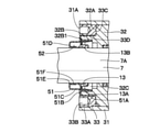
- FIG. 1 and 2 show a first embodiment of the present invention.
- this first embodiment a case where the cylinder is stretched from the end face on the opposite piston side of the closing member and the cover is fixed to the stretched portion of the cylinder is illustrated.
- the hydraulic shock absorber 1 is mounted horizontally between, for example, a vehicle body of a railway vehicle and a bogie (neither of them is shown).
- the hydraulic shock absorber 1 includes an outer cylinder 2, an extension portion 4, an inner cylinder 5, a piston 6, a piston rod 7, a closing member 11, a seal member 13, a cover 17, and a hydraulic oil storage chamber 18, which will be described later.
- the protruding side of the piston rod 7 will be on the left side and the bottom cap 3 side will be on the right side in the state shown in FIG. ..
- the outer cylinder 2 constitutes a cylinder together with the inner cylinder 5.
- the outer cylinder 2 is composed of a cylindrical body extending in the left-right direction, and the right side in the axial direction is closed by the bottom cap 3, and the left side is closed by the closing member 11 or the like described later.
- a screw portion 2A is provided on the inner circumference on the left side of the outer cylinder 2.
- the threaded portion 12A of the lock ring 12, which will be described later, is screwed into the threaded portion 2A.
- the left end portion of the outer cylinder 2 is provided with an extension portion 4 extending from the left end surface 11C1 of the diameter-reduced cylinder portion 11C, which is the end surface on the opposite piston side of the closing member 11, which will be described later.
- the stretched portion 4 constitutes a part of the cover 17, which will be described later.
- the stretched portion 4 is integrally formed on the left side of the outer cylinder 2 as a cylindrical body equivalent to the outer cylinder 2. Further, as shown in FIG. 2, a threaded portion 4A is formed on the inner circumference of the stretched portion 4.
- the threaded portion 17B of the cover 17 is screwed into the threaded portion 4A.
- the stretched portion 4 may be provided as a separate member from the outer cylinder 2 and may be integrally fixed to the outer cylinder 2 by means such as welding, screwing, adhesion, and fitting.
- the inner cylinder 5 is coaxially arranged inside the outer cylinder 2 and constitutes a cylinder together with the outer cylinder 2.
- the inner cylinder 5 is filled with hydraulic oil as a hydraulic liquid. Further, the inner cylinder 5 defines an annular reservoir chamber A between the inner cylinder 5 and the outer cylinder 2, and hydraulic oil and gas are mixed and sealed in the reservoir chamber A.
- the right end side of the inner cylinder 5 is fitted to the base member 9 described later in the axial direction, and the other end side is inserted into the inner peripheral side of the closing member 11 so that the inner cylinder 5 is axially and radially in the outer cylinder 2. Is positioned at.
- the piston 6 is formed as a cylindrical body slidably inserted into the inner cylinder 5.
- the piston 6 divides the inside of the inner cylinder 5 into a bottom side oil chamber B which is one side chamber and a rod side oil chamber C which is another side chamber. Further, the piston 6 is formed with a communication passage 6A that communicates the bottom side oil chamber B and the rod side oil chamber C so as to penetrate in the axial direction.
- the right side of the piston rod 7 is connected to the piston 6 in the inner cylinder 5, and the left side in the axial direction extends to the outside of the outer cylinder 2 via the closing member 11, the sealing member 13, and the like.
- the outer peripheral surface 7A of the piston rod 7 is in sliding contact with the closing member 11 and the sealing member 13.
- the first check valve 8 is provided on the left end surface of the piston 6.
- the first check valve 8 allows hydraulic oil to flow from the bottom side oil chamber B to the rod side oil chamber C via the communication passage 6A, and regulates the reverse flow.
- the base member 9 is located inside the outer cylinder 2 and is attached to the center of the bottom cap 3.
- the base member 9 is formed in a stepped cylindrical shape, and the bottom side oil chamber B in the inner cylinder 5 is closed by fitting the protruding portion on the left side to the right end portion of the inner cylinder 5. Further, the inner peripheral side of the base member 9 is an oil passage 9A.
- the oil passage 9A is connected to the damping force generation mechanism 16 via a communication pipeline 15 described later.
- the second check valve 10 is provided on the base member 9 so as to block the oil passage 9A.
- the second check valve 10 allows hydraulic oil to flow from the communication line 15 toward the bottom oil chamber B, and regulates the reverse flow.
- the closing member 11 is composed of a stepped cylinder provided on the left side of the outer cylinder 2, and closes the left end which is one end of the outer cylinder 2.
- the closing member 11 constitutes a rod guide that guides the piston rod 7 on the inner peripheral side.
- the outer peripheral side of the closing member 11 is fitted in the outer cylinder 2, and the left end portion of the inner cylinder 5 is inserted in the right side portion on the inner peripheral side.
- an oil passage 11A for communicating the communication pipe line 15 and the rod-side oil chamber C is provided on the right side of the closing member 11.
- annular step portion 11B and a cylindrical reduced diameter tubular portion 11C protruding from the inner peripheral side of the step portion 11B to the left side are formed on the left side of the closing member 11.
- the inner peripheral side of the reduced diameter cylinder portion 11C is an inner peripheral hole 11D.
- a seal member 13 described later is inserted into the inner peripheral hole 11D, and a retaining ring 14 described later for retaining the seal member 13 is attached to the left end side of the diameter-reduced cylinder portion 11C.
- the left end surface 11C1 of the diameter-reduced cylinder portion 11C constitutes the end surface on the opposite piston side of the closing member 11.
- the lock ring 12 fixes the closing member 11 in the outer cylinder 2.
- the lock ring 12 is formed as a ring member that fits between the outer cylinder 2 and the diameter-reduced cylinder portion 11C of the closing member 11.
- On the outer peripheral side of the lock ring 12 a threaded portion 12A screwed into the threaded portion 2A of the outer cylinder 2 is formed.
- a plurality of engaging holes 12B (only two are shown) for engaging the rotating tool are formed on the left end surface of the lock ring 12.
- the lock ring 12 has the stepped portion 11B on the right end surface 12C by screwing the threaded portion 12A on the outer peripheral side to the threaded portion 2A of the outer cylinder 2 with the closing member 11 inserted in the outer cylinder 2.
- the closing member 11 can be fixed in the outer cylinder 2 by pressing.
- the seal member 13 is provided in the inner peripheral hole 11D of the closing member 11.
- the seal member 13 includes a cylindrical mounting cylinder portion 13A that is inserted into the inner peripheral hole 11D, and a lip portion 13B that is located on the inner peripheral side of the mounting cylinder portion 13A and slides on the outer peripheral surface 7A of the piston rod 7. have.
- the seal member 13 is fixed to the retaining state by attaching the retaining ring 14 to the diameter-reduced cylinder portion 11C in a state where the mounting cylinder portion 13A is inserted into the inner peripheral hole 11D.
- the communication pipeline 15 is provided in the reservoir chamber A so as to extend in the axial direction.
- the communication pipeline 15 extends over the base member 9 and the closing member 11, and communicates the oil passage 9A of the base member 9 and the oil passage 11A of the closing member 11.
- the damping force generation mechanism 16 is provided in the oil passage 11A of the closing member 11.
- the damping force generation mechanism 16 imparts a flow resistance to the hydraulic oil when the hydraulic oil in the rod side oil chamber C flows toward the bottom side oil chamber B through the communication pipeline 15.
- the cover 17 is provided so as to surround the seal member 13 and the piston rod 7.
- the cover 17 is configured to include the stretched portion 4.
- the cover 17 is made of a flat circular plate, and an opening 17A through which the piston rod 7 is inserted is formed in the center thereof.
- a threaded portion 17B screwed into the threaded portion 4A of the stretched portion 4 is provided on the outer periphery of the cover 17.
- the cover 17 By attaching the cover 17 to the inner peripheral side of the stretched portion 4, the cover 17 cooperates with the stretched portion 4 to form a hydraulic oil storage chamber 18 as a hydraulic liquid storage chamber between the closing member 11 and the sealing member 13. ing.
- the lip portion 13B scratches the hydraulic oil leaked from between the outer peripheral surface 7A of the piston rod 7 and the lip portion 13B of the seal member 13 (the hydraulic oil adhering to the outer peripheral surface 7A of the piston rod 7). It is an annular space where (including the ones taken) are stored.
- the mounting ring 19 is provided on the bottom cap 3.
- the mounting ring 20 is provided at the left end of the piston rod 7.
- One of the mounting ring 19 and the mounting ring 20 is connected to the vehicle body of a railway vehicle or the like, and the other is connected to the bogie.
- the rod cover 21 is formed as a cylindrical body that covers the exposed portion of the piston rod 7.
- a vibration damping device including a horizontal hydraulic shock absorber 1 provided between the bogie and the vehicle body is activated, and the hydraulic shock absorber 1 is a piston.
- the rod 7 is extended and contracted.
- the damping force generation mechanism 16 can generate a damping force and suppress the shaking on the vehicle body side.
- the outer cylinder 2 is provided with the stretched portion 4 extending from the left end surface 11C1 of the reduced diameter cylinder portion 11C of the closing member 11, and the sealing member 13 is provided in the stretched portion 4.
- a cover 17 is provided so as to surround the piston rod 7 and the piston rod 7. As a result, the cover 17 cooperates with the extending portion 4 to form a hydraulic oil storage chamber 18 between the closing member 11 and the sealing member 13. All the hydraulic oil leaked from the hydraulic shock absorber 1 can be stored in the hydraulic oil storage chamber 18.
- the operator prepares a saucer (not shown) under the extension portion 4, and removes the cover 17 from the extension portion 4 to leak into the hydraulic oil storage chamber 18.
- the total amount of hydraulic oil can be visually confirmed. That is, it is possible to clearly determine whether a large amount of hydraulic oil leaks out and affects the buffering performance, or whether a small amount of hydraulic oil leaks out does not affect the cushioning performance.
- the hydraulic shock absorber 1 can be continued to be used. Therefore, unnecessary replacement work of the hydraulic shock absorber 1 is abolished. The running cost can be reduced.
- FIG. 3 shows a second embodiment of the present invention.
- the feature of this embodiment is that the closing member is fixed by a lock ring screwed into the cylinder, and the cover is fixed between the closing member and the lock ring.
- the same components as those in the first embodiment described above are designated by the same reference numerals, and the description thereof will be omitted.
- the outer cylinder 31 according to the second embodiment is formed of a cylindrical body extending in the left-right direction, like the outer cylinder 2 according to the first embodiment, and has a screw portion 31A on the inner circumference on the left side in the axial direction.
- the outer cylinder 31 according to the second embodiment is different from the outer cylinder 2 according to the first embodiment in that the stretched portion 4 of the first embodiment described above is not provided.
- the closing member 32 is composed of a stepped cylindrical body provided on the left side of the outer cylinder 31, and closes the left end of the outer cylinder 31 and is inner.
- a rod guide that guides the piston rod 7 on the peripheral side is configured.
- the closing member 32 includes an oil passage (not shown), a step portion 32A, a diameter reduction cylinder portion 32B, and an inner peripheral hole 32C.
- the left end surface 32B1 of the reduced diameter cylinder portion 32B constitutes the end surface on the opposite piston side of the closing member 32.
- the axial length dimension of the diameter-reduced cylinder portion 32B is shorter than the axial length dimension of the diameter-reduced cylinder portion 11C of the closing member 11 according to the first embodiment. It is formed.
- the length dimension of the reduced diameter cylinder portion 32B is set so that the length dimension of the mounting cylinder portion 13A of the seal member 13 and the inner peripheral hole 32C in the axial direction are equal to each other.
- the lock ring 33 according to the second embodiment is formed as a ring member that fits between the outer cylinder 31 and the reduced diameter cylinder portion 32B of the closing member 32, similarly to the lock ring 12 according to the first embodiment. Further, the lock ring 33 has a screw portion 33A screwed to the screw portion 31A of the outer cylinder 31 on the outer peripheral side, and has a plurality of engagement holes 33B (only two are shown) on the left end surface. Then, the lock ring 33 has the stepped portion 32A on the right end surface 33C by screwing the threaded portion 33A on the outer peripheral side to the threaded portion 31A of the outer cylinder 31 with the closing member 32 inserted in the outer cylinder 31.
- the closing member 32 can be fixed in the outer cylinder 31 by pressing.
- the inner peripheral surface 33D of the lock ring 33 forms a gap between the inner peripheral surface 33D and the reduced diameter cylinder portion 32B in a state where the closing member 32 is fixed in the outer cylinder 31.
- the cover 34 is provided so as to surround the seal member 13 and the piston rod 7.
- the cover 34 is configured as a stepped cylinder made of a thin plate made of metal or resin.
- the cover 34 has a large-diameter cylinder portion 34A located on the right side in the axial direction, a step portion 34B extending inward in the radial direction from the left end portion of the large-diameter cylinder portion 34A, and an inner circumference of the step portion 34B.
- a small diameter cylinder portion 34C extending to the left side from the small diameter cylinder portion 34C, a lid portion 34D extending radially inward from the left end portion of the small diameter cylinder portion 34C, and an opening 34E located in the center of the lid portion 34D through which the piston rod 7 is inserted. It is composed of.
- the large-diameter cylinder portion 34A has a diameter dimension that fits outside the reduced-diameter cylinder portion 32B of the closing member 32, and is sandwiched and fixed between the reduced-diameter cylinder portion 32B and the inner peripheral surface 33D of the lock ring 33. .. Further, the step portion 34B extends inward in the radial direction from the inner peripheral hole 32C of the reduced diameter cylinder portion 32B and is in contact with the left end surface 32B1. As a result, the step portion 34B abuts on the mounting cylinder portion 13A of the seal member 13 in a state of being attached to the closing member 32 side, and the seal member 13 is removed. Further, the lid portion 34D closes between the outer peripheral surface 7A of the piston rod 7 and the small diameter cylinder portion 34C.
- the cover 34 When the cover 34 is attached to the closing member 32 side, the cover 34 stores hydraulic oil as a working liquid storage chamber between the small diameter tubular portion 34C, the lid portion 34D, the outer peripheral surface 7A of the piston rod 7, and the sealing member 13. It forms a chamber 35.
- the hydraulic oil storage chamber 35 is an annular space for storing hydraulic oil leaked from between the piston rod 7 and the seal member 13.
- the cover 34 can be easily manufactured by pressing or molding. Further, since the cover 34 can retain the seal member 13, the retaining ring can be omitted.
- FIG. 4 shows a third embodiment of the present invention.
- the feature of this embodiment is that the closing member is fixed by a lock ring screwed into the cylinder, and the cover is fixed between the closing member and the lock ring.
- the same components as those in the second embodiment described above are designated by the same reference numerals, and the description thereof will be omitted.
- the cover 41 according to the third embodiment includes a large-diameter cylinder portion 41A, a step portion 41B, a small-diameter cylinder portion 41C, a lid portion 41D, and an opening portion 41E, similarly to the cover 34 according to the second embodiment. ing.
- the cover 41 according to the third embodiment is different from the cover 34 according to the second embodiment in that the flange portion 41F is provided at the right end portion of the large diameter tubular portion 41A.
- the cover 41 forms a hydraulic oil storage chamber 42 as a hydraulic liquid storage chamber between the small diameter tubular portion 41C, the lid portion 41D, the outer peripheral surface 7A of the piston rod 7, and the seal member 13.
- the flange portion 41F of the cover 41 is formed as an annular plate extending radially outward from the right end portion of the large diameter tubular portion 41A.
- the flange portion 41F is sandwiched between the step portion 32A of the closing member 32 and the right end portion 33C of the lock ring 33.
- the cover 41 can be mounted at a position surrounding the seal member 13 and the piston rod 7 with high mounting strength.
- the flange portion 41F can be securely attached by sandwiching the flange portion 41F between the step portion 32A of the closing member 32 and the right end portion 33C of the lock ring 33. Moreover, since the flange portion 41F can prevent the hydraulic oil from leaking from the hydraulic oil storage chamber 42 by increasing the liquidtightness between the cover 41 and the closing member 32, the operator can prevent the hydraulic oil from leaking. The total amount of hydraulic oil leaked to the storage chamber 42 can be accurately grasped.
- FIG. 5 shows a fourth embodiment of the present invention.
- the feature of this embodiment is that the inner diameter portion of the cover is bent toward the piston side in the axial direction.
- the same components as those in the second embodiment described above are designated by the same reference numerals, and the description thereof will be omitted.
- the cover 51 according to the fourth embodiment includes a large diameter cylinder portion 51A, a step portion 51B, a small diameter cylinder portion 51C, a lid portion 51D, and an opening portion 51E, similarly to the cover 34 according to the second embodiment. ing.
- the cover 51 according to the fourth embodiment is different from the cover 34 according to the second embodiment in that the return portion 51F is provided at the opening 51E which is the inner diameter portion of the lid portion 51D.
- the cover 51 forms a hydraulic oil storage chamber 52 as a hydraulic liquid storage chamber between the small diameter tubular portion 51C, the lid portion 51D, the outer peripheral surface 7A of the piston rod 7, and the seal member 13.
- the return portion 51F of the cover 51 is formed as a cylindrical body that is bent and extends from the opening 51E of the lid portion 51D to the piston 6 side (seal member 13 side) in the axial direction.
- the return portion 51F can prevent the hydraulic oil collected in the hydraulic oil storage chamber 52 from leaking to the outside of the cover 51 without coming into contact with the outer peripheral surface 7A of the piston rod 7.
- the return portion 51F can prevent the hydraulic oil from leaking from the hydraulic oil storage chamber 52, so that the operator can prevent the hydraulic oil leaking from the hydraulic oil storage chamber 52. It is possible to accurately grasp the total amount of oil.
- FIG. 6 shows a fifth embodiment of the present invention.
- the cover is formed of a transparent material and a scale indicating the capacity inside the cover is formed.
- the hydraulic shock absorber is arranged vertically so that the axes of the cylinder and the piston rod extend in the vertical direction.
- the hydraulic shock absorber in the vertical installation state has the same configuration as the hydraulic shock absorber in the horizontal installation state, such as the piston rod, the closing member, and the seal member.
- the same reference numerals shall be given and the description thereof shall be omitted.
- the cover 61 according to the fifth embodiment includes a large diameter cylinder portion 61A, a step portion 61B, a small diameter cylinder portion 61C, a lid portion 61D, and an opening portion 61E, similarly to the cover 34 according to the second embodiment.
- the cover 61 according to the fifth embodiment is molded from a transparent material such as acrylic, polyethylene terephthalate, polycarbonate, vinyl chloride, fluororesin, and the like, and the capacity inside the cover 61. It differs from the cover 34 according to the second embodiment in that the scale 61F shown is formed.
- the cover 61 forms a hydraulic oil storage chamber 62 as a hydraulic liquid storage chamber between the small diameter tubular portion 61C, the lid portion 61D, the outer peripheral surface 7A of the piston rod 7, and the seal member 13.
- the scale 61F of the cover 61 is formed at an intermediate position in the vertical direction of the small diameter tubular portion 61C in consideration of the fact that the hydraulic oil collects on the seal member 13 side of the hydraulic oil storage chamber 62.
- the position of the scale 61F is arranged, for example, at a position indicating the oil level when the total amount of hydraulic oil leaked to the hydraulic oil storage chamber 62 reaches an amount that affects the cushioning performance. Further, a plurality of scales 61F may be provided, and in this case, attention can be given step by step.
- the cover 61 is made of a transparent material, the amount of leaked hydraulic oil can be visually recognized from the outside without removing the cover 61. Further, since the cover 61 is provided with the scale 61F, it is possible to clarify the criterion for determining whether or not the total amount of the leaked hydraulic oil affects the cushioning performance.
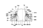
- FIG. 7 shows a sixth embodiment of the present invention.
- the cover is molded from a permeable material and has a float inside the cover made of a material that floats on the working liquid.
- the hydraulic shock absorber is arranged vertically so that the axes of the cylinder and the piston rod extend in the vertical direction.
- the hydraulic shock absorber in the vertical installation state has the same configuration as the hydraulic shock absorber in the horizontal installation state, such as the piston rod, the closing member, and the seal member.
- the same reference numerals shall be given and the description thereof shall be omitted.
- the cover 71 according to the sixth embodiment includes a large diameter cylinder portion 71A, a step portion 71B, a small diameter cylinder portion 71C, a lid portion 71D, and an opening portion 71E, similarly to the cover 34 according to the second embodiment.
- the cover 71 according to the sixth embodiment is according to the second embodiment in that the cover 71 according to the second embodiment is molded from a material having permeability, for example, a resin material such as acrylic, polyethylene terephthalate, polycarbonate, vinyl chloride, and fluororesin. It is different from the cover 34.
- the cover 71 forms a hydraulic oil storage chamber 72 as a hydraulic liquid storage chamber between the small diameter tubular portion 71C, the lid portion 71D, the outer peripheral surface 7A of the piston rod 7, and the seal member 13.
- the float 73 is formed of a material that floats on the hydraulic oil inside the cover 71, that is, in the hydraulic oil storage chamber 72.
- the float 73 is formed of an annular cavity or a resin material that can move up and down along the inner peripheral surface of the small diameter tubular portion 71C. Further, the position of the float 73 can be easily and accurately specified by using a conspicuous color such as red or yellow.
- the cover 71 is made of a transparent material, the position of the float 73 inside can be visually recognized without removing the cover 71.
- the opening 51E which is the inner diameter portion of the lid portion 51D of the cover 51
- the return portion 51F by bending it toward the piston 6 side (seal member 13 side) in the axial direction.
- the present invention is not limited to this, and is returned to, for example, the cover 17 according to the first embodiment, the cover 41 according to the third embodiment, the cover 61 according to the fifth embodiment, and the cover 71 according to the sixth embodiment. It may be configured to provide a portion.
- the fifth embodiment illustrates the case where the cover 61 is molded from a transparent material.
- the present invention is not limited to this, for example, as a configuration in which the cover 17 according to the first embodiment, the cover 41 according to the third embodiment, and the cover 51 according to the fourth embodiment are molded from a material having transparency. May be good.
- the cover 61 is formed of a transparent material and the scale 61F indicating the capacity inside the cover 61 is formed is illustrated.
- the present invention is not limited to this, and for example, the cover 17 according to the first embodiment, the cover 41 according to the third embodiment, and the cover 51 according to the fourth embodiment are molded from a transparent material and are formed. It may be configured to form a scale indicating the capacity inside the cover. Further, a scale may be formed on the cover 71 according to the sixth embodiment.
- a single rod type hydraulic shock absorber 1 in which a closing member 11 for closing one end of the outer cylinder 2 is provided and the piston rod 7 is projected to one end side via the closing member 11 is exemplified.
- the present invention is not limited to this, and the cover of each embodiment can be applied to a double-rod type hydraulic shock absorber in which closing members are provided at both ends of the outer cylinder and both sides of the piston rod are projected.
- the hydraulic shock absorber 1 is provided in a railroad vehicle as an example.
- the present invention is not limited to this, and for example, a buffer used for a four-wheeled vehicle and a two-wheeled vehicle, a shock absorber used for various mechanical devices including general industrial equipment, a shock absorber used for a building, and the like to be buffered. It can also be applied to various shock absorbers that buffer.
- shock absorber based on the embodiment described above, for example, the one described below can be considered.
- the first aspect of the shock absorber is a cylinder in which a working liquid is sealed, a piston inserted into the cylinder to divide the inside of the cylinder into one side chamber and another side chamber, and the piston connected to the piston.
- a piston rod extending to the outside of the cylinder, a closing member that closes at least one end of the cylinder, a sealing member provided in an inner peripheral hole of the closing member and sliding with the piston rod, the sealing member, and the piston rod.
- a cover which surrounds and forms a working liquid storage chamber, is provided.
- the cylinder extends from the anti-piston side end surface of the closing member, and the cover is fixed to the cylinder.
- the closing member is fixed by a lock ring screwed into the cylinder, and the cover is fixed between the closing member and the lock ring. ..
- the inner diameter portion of the cover is bent toward the piston side in the axial direction.
- the cover is molded of a transparent material.
- the cover is formed of a transparent material and a scale indicating the capacity inside the cover is formed.
- the cover includes a float made of a material that floats on the working liquid inside the cover.
- the present invention is not limited to the above-described embodiment, and includes various modifications.
- the above-described embodiment has been described in detail in order to explain the present invention in an easy-to-understand manner, and is not necessarily limited to the one including all the described configurations.
- it is possible to replace a part of the configuration of one embodiment with the configuration of another embodiment and it is also possible to add the configuration of another embodiment to the configuration of one embodiment.
Landscapes
- Engineering & Computer Science (AREA)
- General Engineering & Computer Science (AREA)
- Mechanical Engineering (AREA)
- Fluid-Damping Devices (AREA)
Abstract
A buffer (1) including: an external cylinder (2) and an internal cylinder (5) in which a hydraulic oil is encapsulated; a piston (6) inserted in the internal cylinder and partitioning the internal cylinder into a bottom side oil chamber (B) and a rod side oil chamber (C); a piston rod (7) coupled to the piston and extending out of the external cylinder; a blocking member (11) blocking one end of the external cylinder; a seal member (13) provided in the inner circumferential hole of the blocking member and making sliding contact with the piston rod; and a cover (17) covering the seal member and the piston rod and forming a hydraulic oil storage chamber (18).
Description
本開示は、例えば鉄道車両に搭載され、車両の振動を緩衝するのに好適に用いられる緩衝器に関する。
The present disclosure relates to a shock absorber mounted on a railroad vehicle, for example, and preferably used to cushion the vibration of the vehicle.
一般に、鉄道車両の各台車と車体との間には、作動油等の作動液体を用いた緩衝器が設けられ、鉄道車両の振動を緩衝するようにしている。この種の従来技術による緩衝器は、作動液体が封入されたシリンダと、シリンダ内に挿入されてシリンダ内を一側室と他側室とに分画するピストンと、ピストンに連結されてシリンダの外部へ延びるピストンロッドと、シリンダの少なくとも一端を塞ぐ閉塞部材と、閉塞部材の内周穴に設けられ、ピストンロッドと摺動するシール部材と、を含んで構成されている。
Generally, a shock absorber using a hydraulic liquid such as hydraulic oil is provided between each bogie of a railroad vehicle and the vehicle body to cushion the vibration of the railroad vehicle. This type of prior art shock absorber has a cylinder filled with working liquid, a piston that is inserted into the cylinder and divides the inside of the cylinder into one side chamber and the other side chamber, and is connected to the piston to the outside of the cylinder. It includes an extending piston rod, a closing member that closes at least one end of the cylinder, and a sealing member that is provided in an inner peripheral hole of the closing member and slides on the piston rod.
また、緩衝器には、ピストンロッドとシール部材との間から漏れ出た作動液体を吸収する作動液体吸収部を備えたものがある(特許文献1)。作動液体吸収部は、シール部材を取囲む位置に配置されている。
Further, some shock absorbers are provided with a working liquid absorbing portion that absorbs the working liquid leaked from between the piston rod and the sealing member (Patent Document 1). The working liquid absorbing portion is arranged at a position surrounding the sealing member.
特許文献1の緩衝器は、シリンダやピストンロッドが水平方向に延びた横倒し状態で使用した場合、漏れ出た作動液体の一部は、作動液体吸収部によって吸収される。
When the shock absorber of Patent Document 1 is used in a state where the cylinder or piston rod is extended in the horizontal direction and is laid on its side, a part of the leaked working liquid is absorbed by the working liquid absorbing portion.
ここで、ピストンロッドとシール部材との間から作動液体が漏れ出る原因の一例について述べる。まず、シール部材が損傷して大量の作動液体が漏れ出し、緩衝性能に影響が出る場合がある。一方で、ピストンロッドの外周面に付着した作動液体をシール部材が掻き落とすことで少量の作動液体が漏れ出すものの、緩衝性能に影響が出ない場合がある。
Here, an example of the cause of the hydraulic liquid leaking from between the piston rod and the sealing member will be described. First, the sealing member may be damaged and a large amount of working liquid may leak out, which may affect the cushioning performance. On the other hand, the sealing member scrapes off the working liquid adhering to the outer peripheral surface of the piston rod, so that a small amount of working liquid leaks out, but the cushioning performance may not be affected.
しかし、作動液体吸収部は、漏れ出た作動液体を吸収するだけであるから、作業者は、漏れ出た作動液体の総量を知ることができない。従って、ピストンロッドとシール部材との間から作動液体の漏れが発生した場合には、作動液体が大量に漏れ出したのか、少量しか漏れ出していないのかの判断をすることができない。
However, since the working liquid absorbing unit only absorbs the leaked working liquid, the operator cannot know the total amount of the leaked working liquid. Therefore, when the working liquid leaks from between the piston rod and the seal member, it cannot be determined whether the working liquid has leaked in a large amount or only in a small amount.
このために、作動液体の漏れが発生した場合には、緩衝性能に影響がない少量の作動液体が漏れ出しただけの場合でも、大量の作動液体が漏れ出た場合を想定し、緩衝器の交換を実施している。これにより、定期的なメンテナンス以外にも緩衝器の交換作業が実施されることがあり、ランニングコストが嵩んでしまうという問題がある。
For this reason, when a working liquid leaks, it is assumed that a large amount of working liquid leaks even if only a small amount of working liquid that does not affect the buffering performance leaks. The exchange is being carried out. As a result, the shock absorber may be replaced in addition to the regular maintenance, which causes a problem that the running cost increases.
本発明の一実施形態の目的は、漏れ出た作動液体が少量であることを確認することで、不必要な交換作業を無くすことができるようにした緩衝器を提供することにある。
An object of the embodiment of the present invention is to provide a shock absorber capable of eliminating unnecessary replacement work by confirming that the amount of leaked working liquid is small.
本発明の一実施形態は、作動液体が封入されたシリンダと、前記シリンダ内に挿入されて前記シリンダ内を一側室と他側室とに分画するピストンと、前記ピストンに連結されて前記シリンダの外部へ延びるピストンロッドと、前記シリンダの少なくとも一端を塞ぐ閉塞部材と、前記閉塞部材の内周穴に設けられ、前記ピストンロッドと摺動するシール部材と、前記シール部材と前記ピストンロッドとを囲むと共に作動液体貯留室を形成するカバーと、を備える。
In one embodiment of the present invention, a cylinder in which a working liquid is sealed, a piston inserted into the cylinder to divide the inside of the cylinder into one side chamber and another side chamber, and a piston connected to the piston are connected to the cylinder. It surrounds a piston rod extending to the outside, a closing member that closes at least one end of the cylinder, a sealing member provided in an inner peripheral hole of the closing member and sliding with the piston rod, and the sealing member and the piston rod. It also comprises a cover, which forms a working liquid reservoir.
本発明の一実施形態によれば、漏れ出た作動液体が少量であることを確認することができ、不必要な交換作業を無くして使用期間を延ばすことができる。
According to one embodiment of the present invention, it is possible to confirm that the amount of the leaked working liquid is small, and it is possible to eliminate unnecessary replacement work and extend the period of use.
以下、本発明の実施形態に係る緩衝器を、鉄道車両等に用いられる油圧緩衝器に適用した場合を例に挙げ、添付図面に従って詳細に説明する。
Hereinafter, the case where the shock absorber according to the embodiment of the present invention is applied to a hydraulic shock absorber used for a railway vehicle or the like will be described in detail according to the attached drawings.
図1および図2は本発明の第1の実施形態を示している。この第1の実施形態では、シリンダを閉塞部材の反ピストン側端面よりも延伸し、カバーをシリンダの延伸部に固定した場合を例示している。
1 and 2 show a first embodiment of the present invention. In this first embodiment, a case where the cylinder is stretched from the end face on the opposite piston side of the closing member and the cover is fixed to the stretched portion of the cylinder is illustrated.
図1において、第1の実施形態による油圧緩衝器1は、例えば鉄道車両の車体と台車(いずれも図示せず)との間に横置き状態で取付けられる。この油圧緩衝器1は、後述の外筒2、延伸部4、内筒5、ピストン6、ピストンロッド7、閉塞部材11、シール部材13、カバー17、作動油貯留室18を含んで構成されている。ここで、第1の実施形態では、油圧緩衝器1を横置き状態で配置しているから、図1に示す状態でピストンロッド7の突出側を左側とし、ボトムキャップ3側を右側として説明する。
In FIG. 1, the hydraulic shock absorber 1 according to the first embodiment is mounted horizontally between, for example, a vehicle body of a railway vehicle and a bogie (neither of them is shown). The hydraulic shock absorber 1 includes an outer cylinder 2, an extension portion 4, an inner cylinder 5, a piston 6, a piston rod 7, a closing member 11, a seal member 13, a cover 17, and a hydraulic oil storage chamber 18, which will be described later. There is. Here, in the first embodiment, since the hydraulic shock absorber 1 is arranged in the horizontal state, the protruding side of the piston rod 7 will be on the left side and the bottom cap 3 side will be on the right side in the state shown in FIG. ..
外筒2は、内筒5と一緒にシリンダを構成している。外筒2は、左右方向に延びた円筒体からなり、軸方向の右側がボトムキャップ3により閉塞され、左側が後述の閉塞部材11等により閉塞されている。外筒2の左側の内周には、ねじ部2Aが設けられている。このねじ部2Aには、後述するロックリング12のねじ部12Aが螺合する。
The outer cylinder 2 constitutes a cylinder together with the inner cylinder 5. The outer cylinder 2 is composed of a cylindrical body extending in the left-right direction, and the right side in the axial direction is closed by the bottom cap 3, and the left side is closed by the closing member 11 or the like described later. A screw portion 2A is provided on the inner circumference on the left side of the outer cylinder 2. The threaded portion 12A of the lock ring 12, which will be described later, is screwed into the threaded portion 2A.
ここで、外筒2の左端部には、後述する閉塞部材11の反ピストン側端面となる縮径筒部11Cの左端面11C1よりも延伸して延伸部4が設けられている。延伸部4は、後述するカバー17の一部を構成している。延伸部4は、外筒2と同等の円筒体として外筒2の左側に一体形成されている。また、図2に示すように、延伸部4の内周には、ねじ部4Aが形成されている。このねじ部4Aには、カバー17のねじ部17Bが螺合する。なお、延伸部4は、外筒2と別部材として設け、溶接、螺着、接着、嵌着等の手段を用いて外筒2に一体的に固着する構成としてもよい。
Here, the left end portion of the outer cylinder 2 is provided with an extension portion 4 extending from the left end surface 11C1 of the diameter-reduced cylinder portion 11C, which is the end surface on the opposite piston side of the closing member 11, which will be described later. The stretched portion 4 constitutes a part of the cover 17, which will be described later. The stretched portion 4 is integrally formed on the left side of the outer cylinder 2 as a cylindrical body equivalent to the outer cylinder 2. Further, as shown in FIG. 2, a threaded portion 4A is formed on the inner circumference of the stretched portion 4. The threaded portion 17B of the cover 17 is screwed into the threaded portion 4A. The stretched portion 4 may be provided as a separate member from the outer cylinder 2 and may be integrally fixed to the outer cylinder 2 by means such as welding, screwing, adhesion, and fitting.
内筒5は、外筒2内に同軸に配設され、外筒2と一緒にシリンダを構成している。内筒5内には、作動液体としての作動油が満たされている。また、内筒5は、外筒2との間に環状のリザーバ室Aを画成し、リザーバ室A内には、作動油とガスが混在されて封入されている。そして、内筒5は、軸方向の右端側が後述のベース部材9に嵌合し、他端側が閉塞部材11の内周側に挿嵌されることにより、外筒2内で軸方向および径方向に位置決めされている。
The inner cylinder 5 is coaxially arranged inside the outer cylinder 2 and constitutes a cylinder together with the outer cylinder 2. The inner cylinder 5 is filled with hydraulic oil as a hydraulic liquid. Further, the inner cylinder 5 defines an annular reservoir chamber A between the inner cylinder 5 and the outer cylinder 2, and hydraulic oil and gas are mixed and sealed in the reservoir chamber A. The right end side of the inner cylinder 5 is fitted to the base member 9 described later in the axial direction, and the other end side is inserted into the inner peripheral side of the closing member 11 so that the inner cylinder 5 is axially and radially in the outer cylinder 2. Is positioned at.
ピストン6は、内筒5内に摺動可能に挿入された円筒体として形成されている。ピストン6は、内筒5内を一側室となるボトム側油室Bと他側室となるロッド側油室Cとに分画している。また、ピストン6には、ボトム側油室Bとロッド側油室Cとを連通する連通路6Aが軸方向に貫通して形成されている。
The piston 6 is formed as a cylindrical body slidably inserted into the inner cylinder 5. The piston 6 divides the inside of the inner cylinder 5 into a bottom side oil chamber B which is one side chamber and a rod side oil chamber C which is another side chamber. Further, the piston 6 is formed with a communication passage 6A that communicates the bottom side oil chamber B and the rod side oil chamber C so as to penetrate in the axial direction.
ピストンロッド7は、軸方向の右側が内筒5内でピストン6に連結され、軸方向の左側が閉塞部材11、シール部材13等を介して外筒2の外部へ延びている。ピストンロッド7の外周面7Aは、閉塞部材11とシール部材13に摺接している。
The right side of the piston rod 7 is connected to the piston 6 in the inner cylinder 5, and the left side in the axial direction extends to the outside of the outer cylinder 2 via the closing member 11, the sealing member 13, and the like. The outer peripheral surface 7A of the piston rod 7 is in sliding contact with the closing member 11 and the sealing member 13.
第1チェック弁8は、ピストン6の左端面に設けられている。第1チェック弁8は、ボトム側油室Bから連通路6Aを介してロッド側油室Cに向け作動油が流通するのを許し、逆向きの流れを規制する。
The first check valve 8 is provided on the left end surface of the piston 6. The first check valve 8 allows hydraulic oil to flow from the bottom side oil chamber B to the rod side oil chamber C via the communication passage 6A, and regulates the reverse flow.
ベース部材9は、外筒2内に位置してボトムキャップ3の中央に取付けられている。ベース部材9は、段付円筒状に形成され、左側の突出部分を内筒5の右端部に嵌合させることにより、内筒5内のボトム側油室Bを閉塞している。また、ベース部材9の内周側は、油通路9Aとなっている。この油通路9Aは、後述の連通管路15を介して減衰力発生機構16に接続されている。
The base member 9 is located inside the outer cylinder 2 and is attached to the center of the bottom cap 3. The base member 9 is formed in a stepped cylindrical shape, and the bottom side oil chamber B in the inner cylinder 5 is closed by fitting the protruding portion on the left side to the right end portion of the inner cylinder 5. Further, the inner peripheral side of the base member 9 is an oil passage 9A. The oil passage 9A is connected to the damping force generation mechanism 16 via a communication pipeline 15 described later.
第2チェック弁10は、油通路9Aを閉塞するようにベース部材9に設けられている。第2チェック弁10は、連通管路15からボトム側油室Bに向けて作動油が流通するのを許し、逆向きの流れを規制する。
The second check valve 10 is provided on the base member 9 so as to block the oil passage 9A. The second check valve 10 allows hydraulic oil to flow from the communication line 15 toward the bottom oil chamber B, and regulates the reverse flow.
閉塞部材11は、外筒2の左側に設けられた段付円筒体からなり、外筒2の一端となる左端を塞いでいる。閉塞部材11は、内周側でピストンロッド7をガイドするロッドガイドを構成している。閉塞部材11は、外周側が外筒2内に嵌合され、内周側の右側部分に内筒5の左端部が挿嵌されている。閉塞部材11の右側には、連通管路15とロッド側油室Cとを連通する油通路11Aが設けられている。
The closing member 11 is composed of a stepped cylinder provided on the left side of the outer cylinder 2, and closes the left end which is one end of the outer cylinder 2. The closing member 11 constitutes a rod guide that guides the piston rod 7 on the inner peripheral side. The outer peripheral side of the closing member 11 is fitted in the outer cylinder 2, and the left end portion of the inner cylinder 5 is inserted in the right side portion on the inner peripheral side. On the right side of the closing member 11, an oil passage 11A for communicating the communication pipe line 15 and the rod-side oil chamber C is provided.
一方、図2に示すように、閉塞部材11の左側には、円環状の段部11Bと、段部11Bの内周側から左側に突出した円筒状の縮径筒部11Cとが形成されている。縮径筒部11Cの内周側は、内周穴11Dとなっている。この内周穴11Dには、後述のシール部材13が挿入され、縮径筒部11Cの左端側には、シール部材13を抜止めする後述の止め輪14が取付けられる。また、縮径筒部11Cの左端面11C1は、閉塞部材11の反ピストン側端面を構成している。
On the other hand, as shown in FIG. 2, on the left side of the closing member 11, an annular step portion 11B and a cylindrical reduced diameter tubular portion 11C protruding from the inner peripheral side of the step portion 11B to the left side are formed. There is. The inner peripheral side of the reduced diameter cylinder portion 11C is an inner peripheral hole 11D. A seal member 13 described later is inserted into the inner peripheral hole 11D, and a retaining ring 14 described later for retaining the seal member 13 is attached to the left end side of the diameter-reduced cylinder portion 11C. Further, the left end surface 11C1 of the diameter-reduced cylinder portion 11C constitutes the end surface on the opposite piston side of the closing member 11.
ロックリング12は、外筒2内に閉塞部材11を固定する。ロックリング12は、外筒2と閉塞部材11の縮径筒部11Cとの間に収まるリング部材として形成されている。ロックリング12の外周側には、外筒2のねじ部2Aに螺合するねじ部12Aが形成されている。また、ロックリング12の左端面には、回転用の工具を係合させるための複数個の係合穴12B(2個のみ図示)が形成されている。そして、ロックリング12は、外筒2内に閉塞部材11を挿入した状態で、外周側のねじ部12Aを外筒2のねじ部2Aに螺合させることにより、右端面12Cで段部11Bを押圧して外筒2内に閉塞部材11を固定することができる。
The lock ring 12 fixes the closing member 11 in the outer cylinder 2. The lock ring 12 is formed as a ring member that fits between the outer cylinder 2 and the diameter-reduced cylinder portion 11C of the closing member 11. On the outer peripheral side of the lock ring 12, a threaded portion 12A screwed into the threaded portion 2A of the outer cylinder 2 is formed. Further, a plurality of engaging holes 12B (only two are shown) for engaging the rotating tool are formed on the left end surface of the lock ring 12. Then, the lock ring 12 has the stepped portion 11B on the right end surface 12C by screwing the threaded portion 12A on the outer peripheral side to the threaded portion 2A of the outer cylinder 2 with the closing member 11 inserted in the outer cylinder 2. The closing member 11 can be fixed in the outer cylinder 2 by pressing.
シール部材13は、閉塞部材11の内周穴11Dに設けられている。シール部材13は、内周穴11Dに挿嵌される円筒状の取付筒部13Aと、取付筒部13Aの内周側に位置してピストンロッド7の外周面7Aと摺動するリップ部13Bとを有している。シール部材13は、取付筒部13Aを内周穴11Dに挿嵌した状態で、縮径筒部11Cに止め輪14が取付けられることで、抜止め状態に固定される。
The seal member 13 is provided in the inner peripheral hole 11D of the closing member 11. The seal member 13 includes a cylindrical mounting cylinder portion 13A that is inserted into the inner peripheral hole 11D, and a lip portion 13B that is located on the inner peripheral side of the mounting cylinder portion 13A and slides on the outer peripheral surface 7A of the piston rod 7. have. The seal member 13 is fixed to the retaining state by attaching the retaining ring 14 to the diameter-reduced cylinder portion 11C in a state where the mounting cylinder portion 13A is inserted into the inner peripheral hole 11D.
図1に示すように、連通管路15は、リザーバ室Aに軸方向に延びて設けられている。連通管路15は、ベース部材9と閉塞部材11とに亘って延び、ベース部材9の油通路9Aと閉塞部材11の油通路11Aとを連通している。
As shown in FIG. 1, the communication pipeline 15 is provided in the reservoir chamber A so as to extend in the axial direction. The communication pipeline 15 extends over the base member 9 and the closing member 11, and communicates the oil passage 9A of the base member 9 and the oil passage 11A of the closing member 11.
減衰力発生機構16は、閉塞部材11の油通路11Aに設けられている。減衰力発生機構16は、ロッド側油室C内の作動油が連通管路15を介してボトム側油室Bに向けて流通するときに、作動油に流通抵抗を与えるものである。
The damping force generation mechanism 16 is provided in the oil passage 11A of the closing member 11. The damping force generation mechanism 16 imparts a flow resistance to the hydraulic oil when the hydraulic oil in the rod side oil chamber C flows toward the bottom side oil chamber B through the communication pipeline 15.
次に、本実施形態の特徴部分となるカバー17の構成および機能について詳細に説明する。
Next, the configuration and function of the cover 17, which is a feature of the present embodiment, will be described in detail.
図2に示すように、カバー17は、シール部材13とピストンロッド7とを囲んで設けられている。カバー17は、延伸部4を含んで構成されている。カバー17は、平坦な円形状の板体からなり、その中央には、ピストンロッド7が挿通する開口部17Aが形成されている。一方、カバー17の外周には、延伸部4のねじ部4Aに螺合するねじ部17Bが設けられている。
As shown in FIG. 2, the cover 17 is provided so as to surround the seal member 13 and the piston rod 7. The cover 17 is configured to include the stretched portion 4. The cover 17 is made of a flat circular plate, and an opening 17A through which the piston rod 7 is inserted is formed in the center thereof. On the other hand, on the outer periphery of the cover 17, a threaded portion 17B screwed into the threaded portion 4A of the stretched portion 4 is provided.
カバー17は、延伸部4の内周側に取付けられることで、延伸部4と協働して閉塞部材11、シール部材13との間に作動液体貯留室としての作動油貯留室18を形成している。作動油貯留室18は、ピストンロッド7の外周面7Aとシール部材13のリップ部13Bとの間から漏れ出た作動油(ピストンロッド7の外周面7Aに付着した作動油をリップ部13Bが掻き取ったものを含む)を溜め置く円環状の空間である。
By attaching the cover 17 to the inner peripheral side of the stretched portion 4, the cover 17 cooperates with the stretched portion 4 to form a hydraulic oil storage chamber 18 as a hydraulic liquid storage chamber between the closing member 11 and the sealing member 13. ing. In the hydraulic oil storage chamber 18, the lip portion 13B scratches the hydraulic oil leaked from between the outer peripheral surface 7A of the piston rod 7 and the lip portion 13B of the seal member 13 (the hydraulic oil adhering to the outer peripheral surface 7A of the piston rod 7). It is an annular space where (including the ones taken) are stored.
従って、油圧緩衝器1の点検作業では、カバー17を取外すことにより、作動油貯留室18に溜まった作動油、即ち、ピストンロッド7とシール部材13との間から漏れ出た作動油の総量を確認することができる。
Therefore, in the inspection work of the hydraulic shock absorber 1, by removing the cover 17, the total amount of the hydraulic oil accumulated in the hydraulic oil storage chamber 18, that is, the hydraulic oil leaked from between the piston rod 7 and the seal member 13 is measured. You can check.
なお、図1に示すように、取付環19は、ボトムキャップ3に設けられている。取付環20は、ピストンロッド7の左端部に設けられている。取付環19と取付環20のうち、いずれか一方が鉄道車両等の車体に連結され、他方が台車に連結される。ロッドカバー21は、ピストンロッド7の露出部分を覆う円筒体として形成されている。
As shown in FIG. 1, the mounting ring 19 is provided on the bottom cap 3. The mounting ring 20 is provided at the left end of the piston rod 7. One of the mounting ring 19 and the mounting ring 20 is connected to the vehicle body of a railway vehicle or the like, and the other is connected to the bogie. The rod cover 21 is formed as a cylindrical body that covers the exposed portion of the piston rod 7.
次に、上述のように鉄道車両に取付けた横置き型の油圧緩衝器1の動作および点検作業の一例について説明する。
Next, an example of the operation and inspection work of the horizontal hydraulic shock absorber 1 attached to the railroad vehicle as described above will be described.
まず、軌道に沿って走行する台車が振れを生じた場合、台車と車体との間に設けられた横置き型の油圧緩衝器1を含む制振装置が作動し、油圧緩衝器1は、ピストンロッド7を伸長、縮小させる。これにより、減衰力発生機構16は、減衰力を発生して車体側の揺れを抑制することができる。
First, when the bogie traveling along the track causes vibration, a vibration damping device including a horizontal hydraulic shock absorber 1 provided between the bogie and the vehicle body is activated, and the hydraulic shock absorber 1 is a piston. The rod 7 is extended and contracted. As a result, the damping force generation mechanism 16 can generate a damping force and suppress the shaking on the vehicle body side.
ここで、油圧緩衝器1の動作時には、内部の作動油が漏れ出ることがある。この作動油の漏れは、外筒2に損傷がない場合、ピストンロッド7とシール部材13との間で発生するのが一般的である。一方で、ピストンロッド7とシール部材13との間で発生する作動油の漏れには、シール部材13が損傷することで大量の作動油が漏れ出して緩衝性能に影響が出る場合と、ピストンロッド7の外周面7Aに付着した作動油をシール部材13が掻き落とすことで少量の作動油が漏れ出すものの、緩衝性能に影響が出ない場合とがある。しかし、作動油が大量に漏れ出したのか、少量しか漏れ出していないのかの判断をするのは困難である。
Here, when the hydraulic shock absorber 1 is operating, the hydraulic oil inside may leak out. This leakage of hydraulic oil generally occurs between the piston rod 7 and the sealing member 13 when the outer cylinder 2 is not damaged. On the other hand, in the case of hydraulic oil leakage that occurs between the piston rod 7 and the seal member 13, a large amount of hydraulic oil leaks due to damage to the seal member 13, and the cushioning performance is affected. Although the sealing member 13 scrapes off the hydraulic oil adhering to the outer peripheral surface 7A of 7, a small amount of the hydraulic oil leaks out, but the cushioning performance may not be affected. However, it is difficult to determine whether a large amount of hydraulic oil has leaked or a small amount has leaked.
然るに、本実施形態によれば、外筒2には、閉塞部材11の縮径筒部11Cの左端面11C1よりも延伸して延伸部4を設け、この延伸部4内には、シール部材13とピストンロッド7とを囲んでカバー17を設けている。これにより、カバー17は、延伸部4と協働して閉塞部材11、シール部材13との間に作動油貯留室18を形成している。この作動油貯留室18には、油圧緩衝器1から漏れ出た全ての作動油を溜めることができる。
However, according to the present embodiment, the outer cylinder 2 is provided with the stretched portion 4 extending from the left end surface 11C1 of the reduced diameter cylinder portion 11C of the closing member 11, and the sealing member 13 is provided in the stretched portion 4. A cover 17 is provided so as to surround the piston rod 7 and the piston rod 7. As a result, the cover 17 cooperates with the extending portion 4 to form a hydraulic oil storage chamber 18 between the closing member 11 and the sealing member 13. All the hydraulic oil leaked from the hydraulic shock absorber 1 can be stored in the hydraulic oil storage chamber 18.
従って、油圧緩衝器1の点検作業では、作業者は、延伸部4の下側に受け皿(図示せず)を用意し、延伸部4からカバー17取外すことにより、作動油貯留室18に漏れ出た作動油の総量を目視で確認することができる。即ち、大量の作動油が漏れ出して緩衝性能に影響が出るのか、少量の作動油が漏れ出しただけで緩衝性能に影響が出ないのかを明確に判断することができる。
Therefore, in the inspection work of the hydraulic shock absorber 1, the operator prepares a saucer (not shown) under the extension portion 4, and removes the cover 17 from the extension portion 4 to leak into the hydraulic oil storage chamber 18. The total amount of hydraulic oil can be visually confirmed. That is, it is possible to clearly determine whether a large amount of hydraulic oil leaks out and affects the buffering performance, or whether a small amount of hydraulic oil leaks out does not affect the cushioning performance.
この結果、少量の作動液体が漏れ出しただけで緩衝性能に影響がない場合には、油圧緩衝器1を使い続けることができるから、不必要な油圧緩衝器1の交換作業を廃止して、ランニングコストを低減することができる。
As a result, if only a small amount of hydraulic fluid leaks out and the cushioning performance is not affected, the hydraulic shock absorber 1 can be continued to be used. Therefore, unnecessary replacement work of the hydraulic shock absorber 1 is abolished. The running cost can be reduced.
次に、図3は本発明の第2の実施形態を示している。本実施形態の特徴は、閉塞部材は、シリンダに螺合されるロックリングにより固定され、カバーは、閉塞部材とロックリングとの間に固定されていることにある。なお、第2の実施形態では、前述した第1の実施形態と同一の構成要素に同一の符号を付し、その説明を省略するものとする。
Next, FIG. 3 shows a second embodiment of the present invention. The feature of this embodiment is that the closing member is fixed by a lock ring screwed into the cylinder, and the cover is fixed between the closing member and the lock ring. In the second embodiment, the same components as those in the first embodiment described above are designated by the same reference numerals, and the description thereof will be omitted.
図3において、第2の実施形態による外筒31は、第1の実施形態による外筒2と同様に、左右方向に延びた円筒体からなり、軸方向の左側の内周にねじ部31Aを有している。しかし、第2の実施形態による外筒31は、前述した第1の実施形態の延伸部4が設けられていない点で、第1の実施形態による外筒2と相違している。
In FIG. 3, the outer cylinder 31 according to the second embodiment is formed of a cylindrical body extending in the left-right direction, like the outer cylinder 2 according to the first embodiment, and has a screw portion 31A on the inner circumference on the left side in the axial direction. Have. However, the outer cylinder 31 according to the second embodiment is different from the outer cylinder 2 according to the first embodiment in that the stretched portion 4 of the first embodiment described above is not provided.
第2の実施形態による閉塞部材32は、第1の実施形態による閉塞部材11と同様に、外筒31の左側に設けられた段付円筒体からなり、外筒31の左端を塞ぐと共に、内周側でピストンロッド7をガイドするロッドガイドを構成している。閉塞部材32は、油通路(図示せず)、段部32A、縮径筒部32B、内周穴32Cを備えている。縮径筒部32Bの左端面32B1は、閉塞部材32の反ピストン側端面を構成している。
Similar to the closing member 11 according to the first embodiment, the closing member 32 according to the second embodiment is composed of a stepped cylindrical body provided on the left side of the outer cylinder 31, and closes the left end of the outer cylinder 31 and is inner. A rod guide that guides the piston rod 7 on the peripheral side is configured. The closing member 32 includes an oil passage (not shown), a step portion 32A, a diameter reduction cylinder portion 32B, and an inner peripheral hole 32C. The left end surface 32B1 of the reduced diameter cylinder portion 32B constitutes the end surface on the opposite piston side of the closing member 32.
第2の実施形態による閉塞部材32は、縮径筒部32Bの軸方向の長さ寸法が、第1の実施形態による閉塞部材11の縮径筒部11Cの軸方向の長さ寸法よりも短く形成されている。この場合、縮径筒部32Bの長さ寸法は、シール部材13の取付筒部13Aと内周穴32Cとの軸方向の長さ寸法とが同等になるように設定されている。
In the closing member 32 according to the second embodiment, the axial length dimension of the diameter-reduced cylinder portion 32B is shorter than the axial length dimension of the diameter-reduced cylinder portion 11C of the closing member 11 according to the first embodiment. It is formed. In this case, the length dimension of the reduced diameter cylinder portion 32B is set so that the length dimension of the mounting cylinder portion 13A of the seal member 13 and the inner peripheral hole 32C in the axial direction are equal to each other.
第2の実施形態によるロックリング33は、第1の実施形態によるロックリング12と同様に、外筒31と閉塞部材32の縮径筒部32Bとの間に収まるリング部材として形成されている。また、ロックリング33は、外周側に外筒31のねじ部31Aに螺合するねじ部33Aを有し、左端面に複数個の係合穴33B(2個のみ図示)を有している。そして、ロックリング33は、外筒31内に閉塞部材32を挿入した状態で、外周側のねじ部33Aを外筒31のねじ部31Aに螺合させることにより、右端面33Cで段部32Aを押圧して外筒31内に閉塞部材32を固定することができる。
The lock ring 33 according to the second embodiment is formed as a ring member that fits between the outer cylinder 31 and the reduced diameter cylinder portion 32B of the closing member 32, similarly to the lock ring 12 according to the first embodiment. Further, the lock ring 33 has a screw portion 33A screwed to the screw portion 31A of the outer cylinder 31 on the outer peripheral side, and has a plurality of engagement holes 33B (only two are shown) on the left end surface. Then, the lock ring 33 has the stepped portion 32A on the right end surface 33C by screwing the threaded portion 33A on the outer peripheral side to the threaded portion 31A of the outer cylinder 31 with the closing member 32 inserted in the outer cylinder 31. The closing member 32 can be fixed in the outer cylinder 31 by pressing.
ここで、ロックリング33の内周面33Dは、外筒31内に閉塞部材32を固定した状態で、縮径筒部32Bとの間に隙間を形成している。この隙間には、後述するカバー34の大径筒部34Aが配置されている。
Here, the inner peripheral surface 33D of the lock ring 33 forms a gap between the inner peripheral surface 33D and the reduced diameter cylinder portion 32B in a state where the closing member 32 is fixed in the outer cylinder 31. A large-diameter tubular portion 34A of the cover 34, which will be described later, is arranged in this gap.
第2の実施形態によるカバー34は、シール部材13とピストンロッド7とを囲んで設けられている。カバー34は、金属製または樹脂製の薄板からなる段付き円筒体として構成されている。具体的には、カバー34は、軸方向の右側に位置する大径筒部34Aと、大径筒部34Aの左端部から径方向の内側に延びた段差部34Bと、段差部34Bの内周から左側に延びた小径筒部34Cと、小径筒部34Cの左端部から径方向の内側に延びた蓋部34Dと、蓋部34Dの中央に位置してピストンロッド7が挿通する開口部34Eとにより構成されている。
The cover 34 according to the second embodiment is provided so as to surround the seal member 13 and the piston rod 7. The cover 34 is configured as a stepped cylinder made of a thin plate made of metal or resin. Specifically, the cover 34 has a large-diameter cylinder portion 34A located on the right side in the axial direction, a step portion 34B extending inward in the radial direction from the left end portion of the large-diameter cylinder portion 34A, and an inner circumference of the step portion 34B. A small diameter cylinder portion 34C extending to the left side from the small diameter cylinder portion 34C, a lid portion 34D extending radially inward from the left end portion of the small diameter cylinder portion 34C, and an opening 34E located in the center of the lid portion 34D through which the piston rod 7 is inserted. It is composed of.
大径筒部34Aは、閉塞部材32の縮径筒部32Bに外嵌する径寸法を有し、縮径筒部32Bとロックリング33の内周面33Dとの間に挟まれて固定される。また、段差部34Bは、縮径筒部32Bの内周穴32Cよりも径方向の内側に延びて左端面32B1に当接している。これにより、段差部34Bは、閉塞部材32側に取付けられた状態で、シール部材13の取付筒部13Aに当接してシール部材13を抜止めする。さらに、蓋部34Dは、ピストンロッド7の外周面7Aと小径筒部34Cとの間を閉塞している。
The large-diameter cylinder portion 34A has a diameter dimension that fits outside the reduced-diameter cylinder portion 32B of the closing member 32, and is sandwiched and fixed between the reduced-diameter cylinder portion 32B and the inner peripheral surface 33D of the lock ring 33. .. Further, the step portion 34B extends inward in the radial direction from the inner peripheral hole 32C of the reduced diameter cylinder portion 32B and is in contact with the left end surface 32B1. As a result, the step portion 34B abuts on the mounting cylinder portion 13A of the seal member 13 in a state of being attached to the closing member 32 side, and the seal member 13 is removed. Further, the lid portion 34D closes between the outer peripheral surface 7A of the piston rod 7 and the small diameter cylinder portion 34C.
カバー34を閉塞部材32側に取付けた状態では、カバー34は、小径筒部34Cと蓋部34Dとピストンロッド7の外周面7Aとシール部材13との間に作動液体貯留室としての作動油貯留室35を形成している。作動油貯留室35は、ピストンロッド7とシール部材13との間から漏れ出た作動油を溜め置く円環状の空間である。
When the cover 34 is attached to the closing member 32 side, the cover 34 stores hydraulic oil as a working liquid storage chamber between the small diameter tubular portion 34C, the lid portion 34D, the outer peripheral surface 7A of the piston rod 7, and the sealing member 13. It forms a chamber 35. The hydraulic oil storage chamber 35 is an annular space for storing hydraulic oil leaked from between the piston rod 7 and the seal member 13.
従って、点検作業時には、ロックリング33を緩めてカバー34を取外すことにより、作動油貯留室35に溜まった作動油、即ち、ピストンロッド7とシール部材13との間から漏れ出た作動油の総量を確認することができる。
Therefore, at the time of inspection work, by loosening the lock ring 33 and removing the cover 34, the total amount of hydraulic oil accumulated in the hydraulic oil storage chamber 35, that is, the total amount of hydraulic oil leaked from between the piston rod 7 and the seal member 13. Can be confirmed.
かくして、このように構成された第2の実施形態においても、前述した第1の実施形態とほぼ同様の作用効果を得ることができる。特に、第2の実施形態によれば、カバー34は、プレスや型成形によって容易に製造することができる。また、カバー34は、シール部材13を抜止めできるから、止め輪を省略することができる。
Thus, even in the second embodiment configured in this way, it is possible to obtain almost the same action and effect as in the above-mentioned first embodiment. In particular, according to the second embodiment, the cover 34 can be easily manufactured by pressing or molding. Further, since the cover 34 can retain the seal member 13, the retaining ring can be omitted.
次に、図4は本発明の第3の実施形態を示している。本実施形態の特徴は、閉塞部材は、シリンダに螺合されるロックリングにより固定され、カバーは、閉塞部材とロックリングとの間に固定されていることにある。なお、第3の実施形態では、前述した第2の実施形態と同一の構成要素に同一の符号を付し、その説明を省略するものとする。
Next, FIG. 4 shows a third embodiment of the present invention. The feature of this embodiment is that the closing member is fixed by a lock ring screwed into the cylinder, and the cover is fixed between the closing member and the lock ring. In the third embodiment, the same components as those in the second embodiment described above are designated by the same reference numerals, and the description thereof will be omitted.
図4において、第3の実施形態によるカバー41は、第2の実施形態によるカバー34と同様に、大径筒部41A、段差部41B、小径筒部41C、蓋部41Dおよび開口部41Eを備えている。しかし、第3の実施形態によるカバー41は、大径筒部41Aの右端部に鍔部41Fが設けられている点で、第2の実施形態によるカバー34と相違している。また、カバー41は、小径筒部41Cと蓋部41Dとピストンロッド7の外周面7Aとシール部材13との間に作動液体貯留室としての作動油貯留室42を形成している。
In FIG. 4, the cover 41 according to the third embodiment includes a large-diameter cylinder portion 41A, a step portion 41B, a small-diameter cylinder portion 41C, a lid portion 41D, and an opening portion 41E, similarly to the cover 34 according to the second embodiment. ing. However, the cover 41 according to the third embodiment is different from the cover 34 according to the second embodiment in that the flange portion 41F is provided at the right end portion of the large diameter tubular portion 41A. Further, the cover 41 forms a hydraulic oil storage chamber 42 as a hydraulic liquid storage chamber between the small diameter tubular portion 41C, the lid portion 41D, the outer peripheral surface 7A of the piston rod 7, and the seal member 13.
カバー41の鍔部41Fは、大径筒部41Aの右端部から径方向の外側に延びた円環状の板体として形成されている。この鍔部41Fは、閉塞部材32の段部32Aとロックリング33の右端部33Cとの間に挟まれる。これにより、カバー41は、シール部材13とピストンロッド7とを囲む位置に高い取付強度をもって取付けることができる。
The flange portion 41F of the cover 41 is formed as an annular plate extending radially outward from the right end portion of the large diameter tubular portion 41A. The flange portion 41F is sandwiched between the step portion 32A of the closing member 32 and the right end portion 33C of the lock ring 33. As a result, the cover 41 can be mounted at a position surrounding the seal member 13 and the piston rod 7 with high mounting strength.
かくして、このように構成された第3の実施形態においても、前述した第2の実施形態とほぼ同様の作用効果を得ることができる。特に、第3の実施形態によれば、鍔部41Fを閉塞部材32の段部32Aとロックリング33の右端部33Cとの間に挟むことにより、確実に取付けることができる。しかも、鍔部41Fは、カバー41と閉塞部材32との間の液密性を高めることにより、作動油貯留室42からの作動油の漏れを防止することができるから、作業者は、作動油貯留室42に漏れ出た作動油の総量を正確に把握することができる。
Thus, even in the third embodiment configured in this way, it is possible to obtain almost the same action and effect as in the above-mentioned second embodiment. In particular, according to the third embodiment, the flange portion 41F can be securely attached by sandwiching the flange portion 41F between the step portion 32A of the closing member 32 and the right end portion 33C of the lock ring 33. Moreover, since the flange portion 41F can prevent the hydraulic oil from leaking from the hydraulic oil storage chamber 42 by increasing the liquidtightness between the cover 41 and the closing member 32, the operator can prevent the hydraulic oil from leaking. The total amount of hydraulic oil leaked to the storage chamber 42 can be accurately grasped.
次に、図5は本発明の第4の実施形態を示している。本実施形態の特徴は、カバーの内径部分は、軸方向のピストン側に折り曲げられていることにある。なお、第4の実施形態では、前述した第2の実施形態と同一の構成要素に同一の符号を付し、その説明を省略するものとする。
Next, FIG. 5 shows a fourth embodiment of the present invention. The feature of this embodiment is that the inner diameter portion of the cover is bent toward the piston side in the axial direction. In the fourth embodiment, the same components as those in the second embodiment described above are designated by the same reference numerals, and the description thereof will be omitted.
図5において、第4の実施形態によるカバー51は、第2の実施形態によるカバー34と同様に、大径筒部51A、段差部51B、小径筒部51C、蓋部51Dおよび開口部51Eを備えている。しかし、第4の実施形態によるカバー51は、蓋部51Dの内径部分となる開口部51Eに返し部51Fが設けられている点で、第2の実施形態によるカバー34と相違している。また、カバー51は、小径筒部51Cと蓋部51Dとピストンロッド7の外周面7Aとシール部材13との間に作動液体貯留室としての作動油貯留室52を形成している。
In FIG. 5, the cover 51 according to the fourth embodiment includes a large diameter cylinder portion 51A, a step portion 51B, a small diameter cylinder portion 51C, a lid portion 51D, and an opening portion 51E, similarly to the cover 34 according to the second embodiment. ing. However, the cover 51 according to the fourth embodiment is different from the cover 34 according to the second embodiment in that the return portion 51F is provided at the opening 51E which is the inner diameter portion of the lid portion 51D. Further, the cover 51 forms a hydraulic oil storage chamber 52 as a hydraulic liquid storage chamber between the small diameter tubular portion 51C, the lid portion 51D, the outer peripheral surface 7A of the piston rod 7, and the seal member 13.
カバー51の返し部51Fは、蓋部51Dの開口部51Eから軸方向のピストン6側(シール部材13側)に折り曲げられて延びた円筒体として形成されている。この返し部51Fは、ピストンロッド7の外周面7Aに接触することなく、作動油貯留室52に溜まった作動油がカバー51の外部に漏れ出るのを防止することができる。
The return portion 51F of the cover 51 is formed as a cylindrical body that is bent and extends from the opening 51E of the lid portion 51D to the piston 6 side (seal member 13 side) in the axial direction. The return portion 51F can prevent the hydraulic oil collected in the hydraulic oil storage chamber 52 from leaking to the outside of the cover 51 without coming into contact with the outer peripheral surface 7A of the piston rod 7.
かくして、このように構成された第4の実施形態においても、前述した第2の実施形態とほぼ同様の作用効果を得ることができる。特に、第4の実施形態によれば、返し部51Fは、作動油貯留室52からの作動油の漏れを防止することができるから、作業者は、作動油貯留室52に漏れ出た作動油の総量を正確に把握することができる。
Thus, even in the fourth embodiment configured in this way, it is possible to obtain substantially the same action and effect as in the above-mentioned second embodiment. In particular, according to the fourth embodiment, the return portion 51F can prevent the hydraulic oil from leaking from the hydraulic oil storage chamber 52, so that the operator can prevent the hydraulic oil leaking from the hydraulic oil storage chamber 52. It is possible to accurately grasp the total amount of oil.
次に、図6は本発明の第5の実施形態を示している。本実施形態の特徴は、カバーは、透過性を有する素材で成形されると共に、カバー内部の容量を示す目盛りが形成されていることにある。なお、第5の実施形態では、シリンダやピストンロッドの軸線が上下方向に延びるように油圧緩衝器が縦置き状態に配置されている。この場合、縦置き状態の油圧緩衝器は、ピストンロッド、閉塞部材、シール部材等の構成が横置き状態の油圧緩衝器と同様であるため、前述した第2の実施形態と同一の構成要素に同一の符号を付し、その説明を省略するものとする。
Next, FIG. 6 shows a fifth embodiment of the present invention. The feature of this embodiment is that the cover is formed of a transparent material and a scale indicating the capacity inside the cover is formed. In the fifth embodiment, the hydraulic shock absorber is arranged vertically so that the axes of the cylinder and the piston rod extend in the vertical direction. In this case, the hydraulic shock absorber in the vertical installation state has the same configuration as the hydraulic shock absorber in the horizontal installation state, such as the piston rod, the closing member, and the seal member. The same reference numerals shall be given and the description thereof shall be omitted.
図6において、第5の実施形態によるカバー61は、第2の実施形態によるカバー34と同様に、大径筒部61A、段差部61B、小径筒部61C、蓋部61Dおよび開口部61Eを備えている。しかし、第5の実施形態によるカバー61は、透過性を有する素材、例えば、アクリル、ポリエチレンテレフタレート、ポリカーボネート、塩化ビニール、フッ素樹脂等の樹脂材料で成形されている点と、カバー61内部の容量を示す目盛り61Fが形成されている点とで、第2の実施形態によるカバー34と相違している。また、カバー61は、小径筒部61Cと蓋部61Dとピストンロッド7の外周面7Aとシール部材13との間に作動液体貯留室としての作動油貯留室62を形成している。
In FIG. 6, the cover 61 according to the fifth embodiment includes a large diameter cylinder portion 61A, a step portion 61B, a small diameter cylinder portion 61C, a lid portion 61D, and an opening portion 61E, similarly to the cover 34 according to the second embodiment. ing. However, the cover 61 according to the fifth embodiment is molded from a transparent material such as acrylic, polyethylene terephthalate, polycarbonate, vinyl chloride, fluororesin, and the like, and the capacity inside the cover 61. It differs from the cover 34 according to the second embodiment in that the scale 61F shown is formed. Further, the cover 61 forms a hydraulic oil storage chamber 62 as a hydraulic liquid storage chamber between the small diameter tubular portion 61C, the lid portion 61D, the outer peripheral surface 7A of the piston rod 7, and the seal member 13.
カバー61の目盛り61Fは、作動油が作動油貯留室62のシール部材13側に溜まることを考慮し、小径筒部61Cの上下方向の途中位置に形成されている。目盛り61Fの位置は、例えば、作動油貯留室62に漏れ出た作動油の総量が、緩衝性能に影響が出る量に達したときの油面を示す位置に配置されている。また、目盛り61Fは、複数本設ける構成としてもよく、この場合には、段階的に注意を促すことができる。
The scale 61F of the cover 61 is formed at an intermediate position in the vertical direction of the small diameter tubular portion 61C in consideration of the fact that the hydraulic oil collects on the seal member 13 side of the hydraulic oil storage chamber 62. The position of the scale 61F is arranged, for example, at a position indicating the oil level when the total amount of hydraulic oil leaked to the hydraulic oil storage chamber 62 reaches an amount that affects the cushioning performance. Further, a plurality of scales 61F may be provided, and in this case, attention can be given step by step.
かくして、このように構成された第5の実施形態においても、前述した第2の実施形態とほぼ同様の作用効果を得ることができる。特に、第5の実施形態によれば、カバー61は、透過性を有する素材によって形成しているから、カバー61を取外すことなく、漏れ出た作動油の量を外部から視認することができる。また、カバー61には、目盛り61Fを設けているから、漏れ出た作動油の総量が緩衝性能に影響が出るか否かの判断基準を明確にすることができる。
Thus, even in the fifth embodiment configured in this way, substantially the same action and effect as in the above-mentioned second embodiment can be obtained. In particular, according to the fifth embodiment, since the cover 61 is made of a transparent material, the amount of leaked hydraulic oil can be visually recognized from the outside without removing the cover 61. Further, since the cover 61 is provided with the scale 61F, it is possible to clarify the criterion for determining whether or not the total amount of the leaked hydraulic oil affects the cushioning performance.
次に、図7は本発明の第6の実施形態を示している。本実施形態の特徴は、カバーは、透過性を有する素材で成形されると共に、そのカバーの内部に作動液体に浮かぶ素材で形成されたフロートを備えていることにある。なお、第6の実施形態では、シリンダやピストンロッドの軸線が上下方向に延びるように油圧緩衝器が縦置き状態に配置されている。この場合、縦置き状態の油圧緩衝器は、ピストンロッド、閉塞部材、シール部材等の構成が横置き状態の油圧緩衝器と同様であるため、前述した第2の実施形態と同一の構成要素に同一の符号を付し、その説明を省略するものとする。
Next, FIG. 7 shows a sixth embodiment of the present invention. A feature of this embodiment is that the cover is molded from a permeable material and has a float inside the cover made of a material that floats on the working liquid. In the sixth embodiment, the hydraulic shock absorber is arranged vertically so that the axes of the cylinder and the piston rod extend in the vertical direction. In this case, the hydraulic shock absorber in the vertical installation state has the same configuration as the hydraulic shock absorber in the horizontal installation state, such as the piston rod, the closing member, and the seal member. The same reference numerals shall be given and the description thereof shall be omitted.
図7において、第6の実施形態によるカバー71は、第2の実施形態によるカバー34と同様に、大径筒部71A、段差部71B、小径筒部71C、蓋部71Dおよび開口部71Eを備えている。しかし、第6の実施形態によるカバー71は、透過性を有する素材、例えば、アクリル、ポリエチレンテレフタレート、ポリカーボネート、塩化ビニール、フッ素樹脂等の樹脂材料で成形されている点で、第2の実施形態によるカバー34と相違している。また、カバー71は、小径筒部71Cと蓋部71Dとピストンロッド7の外周面7Aとシール部材13との間に作動液体貯留室としての作動油貯留室72を形成している。
In FIG. 7, the cover 71 according to the sixth embodiment includes a large diameter cylinder portion 71A, a step portion 71B, a small diameter cylinder portion 71C, a lid portion 71D, and an opening portion 71E, similarly to the cover 34 according to the second embodiment. ing. However, the cover 71 according to the sixth embodiment is according to the second embodiment in that the cover 71 according to the second embodiment is molded from a material having permeability, for example, a resin material such as acrylic, polyethylene terephthalate, polycarbonate, vinyl chloride, and fluororesin. It is different from the cover 34. Further, the cover 71 forms a hydraulic oil storage chamber 72 as a hydraulic liquid storage chamber between the small diameter tubular portion 71C, the lid portion 71D, the outer peripheral surface 7A of the piston rod 7, and the seal member 13.
フロート73は、カバー71の内部、即ち、作動油貯留室72に作動油に浮かぶ素材で形成されている。フロート73は、小径筒部71Cの内周面に沿って上下方向に移動可能な円環状の空洞体または樹脂材によって形成されている。また、フロート73は、赤色、黄色等の目立つ色とすることにより、容易かつ正確に位置を特定することができる。
The float 73 is formed of a material that floats on the hydraulic oil inside the cover 71, that is, in the hydraulic oil storage chamber 72. The float 73 is formed of an annular cavity or a resin material that can move up and down along the inner peripheral surface of the small diameter tubular portion 71C. Further, the position of the float 73 can be easily and accurately specified by using a conspicuous color such as red or yellow.
かくして、このように構成された第6の実施形態においても、前述した第2の実施形態とほぼ同様の作用効果を得ることができる。特に、第5の実施形態によれば、カバー71は、透過性を有する素材によって形成しているから、カバー71を取外すことなく、内部のフロート73の位置を視認することができる。
Thus, even in the sixth embodiment configured in this way, it is possible to obtain substantially the same action and effect as in the above-mentioned second embodiment. In particular, according to the fifth embodiment, since the cover 71 is made of a transparent material, the position of the float 73 inside can be visually recognized without removing the cover 71.
なお、第4の実施形態では、カバー51の蓋部51Dの内径部分となる開口部51Eに、軸方向のピストン6側(シール部材13側)に折り曲げて返し部51Fを設けた場合を例示している。しかし、本発明はこれに限らず、例えば、第1の実施形態によるカバー17、第3の実施形態によるカバー41、第5の実施形態によるカバー61、第6の実施形態によるカバー71に、返し部を設ける構成としてもよい。
In the fourth embodiment, the case where the opening 51E, which is the inner diameter portion of the lid portion 51D of the cover 51, is provided with the return portion 51F by bending it toward the piston 6 side (seal member 13 side) in the axial direction is exemplified. ing. However, the present invention is not limited to this, and is returned to, for example, the cover 17 according to the first embodiment, the cover 41 according to the third embodiment, the cover 61 according to the fifth embodiment, and the cover 71 according to the sixth embodiment. It may be configured to provide a portion.
第5の実施形態では、透過性を有する素材でカバー61を成形した場合を例示している。しかし、本発明はこれに限らず、例えば、第1の実施形態によるカバー17、第3の実施形態によるカバー41、第4の実施形態によるカバー51を、透過性を有する素材で成形する構成としてもよい。
The fifth embodiment illustrates the case where the cover 61 is molded from a transparent material. However, the present invention is not limited to this, for example, as a configuration in which the cover 17 according to the first embodiment, the cover 41 according to the third embodiment, and the cover 51 according to the fourth embodiment are molded from a material having transparency. May be good.
第5の実施形態では、透過性を有する素材でカバー61を成形すると共に、カバー61内部の容量を示す目盛り61Fを形成した場合を例示している。しかし、本発明はこれに限らず、例えば、第1の実施形態によるカバー17、第3の実施形態によるカバー41、第4の実施形態によるカバー51を、透過性を有する素材で成形すると共に、カバー内部の容量を示す目盛りを形成する構成としてもよい。また、第6の実施形態によるカバー71に目盛りを形成する構成としてもよい。
In the fifth embodiment, the case where the cover 61 is formed of a transparent material and the scale 61F indicating the capacity inside the cover 61 is formed is illustrated. However, the present invention is not limited to this, and for example, the cover 17 according to the first embodiment, the cover 41 according to the third embodiment, and the cover 51 according to the fourth embodiment are molded from a transparent material and are formed. It may be configured to form a scale indicating the capacity inside the cover. Further, a scale may be formed on the cover 71 according to the sixth embodiment.
第1の実施形態では、外筒2の一端を塞ぐ閉塞部材11を設け、閉塞部材11を介してピストンロッド7を一端側に突出させた片ロッド式の油圧緩衝器1を例示している。しかし、本発明はこれに限らず、外筒の両端に閉塞部材を設け、ピストンロッドの両側を突出させた両ロッド式の油圧緩衝器に、各実施形態のカバーを適用することもできる。
In the first embodiment, a single rod type hydraulic shock absorber 1 in which a closing member 11 for closing one end of the outer cylinder 2 is provided and the piston rod 7 is projected to one end side via the closing member 11 is exemplified. However, the present invention is not limited to this, and the cover of each embodiment can be applied to a double-rod type hydraulic shock absorber in which closing members are provided at both ends of the outer cylinder and both sides of the piston rod are projected.
各実施形態では、油圧緩衝器1を鉄道車両に設ける場合を例に挙げて説明した。しかし、本発明はこれに限らず、例えば、4輪自動車および2輪車に用いる緩衝器、一般産業機器を含む各種の機械機器に用いる緩衝器、建築物に用いる緩衝器等、緩衝すべき対象を緩衝する各種の緩衝器にも適用することができる。
In each embodiment, the case where the hydraulic shock absorber 1 is provided in a railroad vehicle has been described as an example. However, the present invention is not limited to this, and for example, a buffer used for a four-wheeled vehicle and a two-wheeled vehicle, a shock absorber used for various mechanical devices including general industrial equipment, a shock absorber used for a building, and the like to be buffered. It can also be applied to various shock absorbers that buffer.
以上説明した実施形態に基づく緩衝器として、例えば、以下に述べる態様のものが考えられる。
As the shock absorber based on the embodiment described above, for example, the one described below can be considered.
緩衝器の第1の態様としては、作動液体が封入されたシリンダと、前記シリンダ内に挿入されて前記シリンダ内を一側室と他側室とに分画するピストンと、前記ピストンに連結されて前記シリンダの外部へ延びるピストンロッドと、前記シリンダの少なくとも一端を塞ぐ閉塞部材と、前記閉塞部材の内周穴に設けられ、前記ピストンロッドと摺動するシール部材と、前記シール部材と前記ピストンロッドとを囲むと共に作動液体貯留室を形成するカバーと、を備える。
The first aspect of the shock absorber is a cylinder in which a working liquid is sealed, a piston inserted into the cylinder to divide the inside of the cylinder into one side chamber and another side chamber, and the piston connected to the piston. A piston rod extending to the outside of the cylinder, a closing member that closes at least one end of the cylinder, a sealing member provided in an inner peripheral hole of the closing member and sliding with the piston rod, the sealing member, and the piston rod. A cover, which surrounds and forms a working liquid storage chamber, is provided.
第2の態様としては、第1の態様において、前記シリンダは、前記閉塞部材の反ピストン側端面よりも延伸し、前記カバーは、前記シリンダに固定されている。
As a second aspect, in the first aspect, the cylinder extends from the anti-piston side end surface of the closing member, and the cover is fixed to the cylinder.
第3の態様としては、第1の態様において、前記閉塞部材は、前記シリンダに螺合されるロックリングにより固定され、前記カバーは、前記閉塞部材と前記ロックリングとの間に固定されている。
As a third aspect, in the first aspect, the closing member is fixed by a lock ring screwed into the cylinder, and the cover is fixed between the closing member and the lock ring. ..
第4の態様としては、第1乃至3のいずれかの態様において、前記カバーの内径部分は、軸方向の前記ピストン側に折り曲げられている。
As a fourth aspect, in any one of the first to third aspects, the inner diameter portion of the cover is bent toward the piston side in the axial direction.
第5の態様としては、第1乃至4のいずれかの態様において、前記カバーは、透過性を有する素材で成形されている。
As a fifth aspect, in any one of the first to fourth aspects, the cover is molded of a transparent material.
第6の態様としては、第1乃至4のいずれかの態様において、前記カバーは、透過性を有する素材で成形されると共に、前記カバー内部の容量を示す目盛りが形成されている。
As a sixth aspect, in any one of the first to fourth aspects, the cover is formed of a transparent material and a scale indicating the capacity inside the cover is formed.
第7の態様としては、第1乃至5のいずれかの態様において、前記カバーは、当該カバー内部に、作動液体に浮かぶ素材で形成されたフロートを備える。
As a seventh aspect, in any one of the first to fifth aspects, the cover includes a float made of a material that floats on the working liquid inside the cover.
尚、本発明は上記した実施形態に限定されるものではなく、様々な変形例が含まれる。例えば、上記した実施形態は本発明を分かりやすく説明するために詳細に説明したものであり、必ずしも説明した全ての構成を備えるものに限定されるものではない。また、ある実施形態の構成の一部を他の実施形態の構成に置き換えることが可能であり、また、ある実施形態の構成に他の実施形態の構成を加えることも可能である。また、各実施形態の構成の一部について、他の構成の追加・削除・置換をすることが可能である。
The present invention is not limited to the above-described embodiment, and includes various modifications. For example, the above-described embodiment has been described in detail in order to explain the present invention in an easy-to-understand manner, and is not necessarily limited to the one including all the described configurations. Further, it is possible to replace a part of the configuration of one embodiment with the configuration of another embodiment, and it is also possible to add the configuration of another embodiment to the configuration of one embodiment. Further, it is possible to add / delete / replace a part of the configuration of each embodiment with another configuration.
本願は、2020年9月1日付出願の日本国特許出願第2020-146826号に基づく優先権を主張する。2020年9月1日付出願の日本国特許出願第2020-146826号の明細書、特許請求の範囲、図面、及び要約書を含む全開示内容は、参照により本願に全体として組み込まれる。
This application claims priority based on Japanese Patent Application No. 2020-146826 filed on September 1, 2020. The entire disclosure, including the specification, claims, drawings, and abstracts of Japanese Patent Application No. 2020-146826 filed September 1, 2020, is incorporated herein by reference in its entirety.
1 油圧緩衝器(緩衝器) 2,31 外筒(シリンダ) 4 延伸部 5 内筒(シリンダ) 6 ピストン 7 ピストンロッド 11,32 閉塞部材 11C1,32B1 左端面(反ピストン側端面) 11D,32C 内周穴 12,33 ロックリング 13 シール部材 17,34,41,51,61,71 カバー 18,35,42,52,62,72 作動油貯留室(作動液体貯留室) 51E 開口部(内径部分) 51F 返し部 61F 目盛り 73 フロート B ボトム側油室(一側室) C ロッド側油室(他側室)
1 Hydraulic shock absorber (buffer) 2, 31 Outer cylinder (cylinder) 4 Extension part 5 Inner cylinder (cylinder) 6 Piston 7 Piston rod 11, 32 Closing member 11C1, 32B1 Left end face (anti-piston side end face) 11D, 32C Peripheral hole 12, 33 Lock ring 13 Seal member 17, 34, 41, 51, 61, 71 Cover 18, 35, 42, 52, 62, 72 Hydraulic oil storage chamber (working liquid storage chamber) 51E Opening (inner diameter part) 51F return part 61F scale 73 float B bottom side oil chamber (one side chamber) C rod side oil chamber (other side chamber)
Claims (7)
- 作動液体が封入されたシリンダと、
前記シリンダ内に挿入されて前記シリンダ内を一側室と他側室とに分画するピストンと、
前記ピストンに連結されて前記シリンダの外部へ延びるピストンロッドと、
前記シリンダの少なくとも一端を塞ぐ閉塞部材と、
前記閉塞部材の内周穴に設けられ、前記ピストンロッドと摺動するシール部材と、
前記シール部材と前記ピストンロッドとを囲むと共に作動液体貯留室を形成するカバーと、を備える緩衝器。 A cylinder filled with working liquid and
A piston that is inserted into the cylinder and divides the inside of the cylinder into a concubine and a concubine.
A piston rod that is connected to the piston and extends to the outside of the cylinder,
A closing member that closes at least one end of the cylinder,
A seal member provided in the inner peripheral hole of the closing member and sliding with the piston rod,
A shock absorber comprising a cover that surrounds the seal member and the piston rod and forms a working liquid reservoir. - 請求項1に記載の緩衝器において、
前記シリンダは、前記閉塞部材の反ピストン側端面よりも延伸し、
前記カバーは、前記シリンダに固定されている緩衝器。 In the shock absorber according to claim 1,
The cylinder extends from the opposite end face of the closing member on the anti-piston side.
The cover is a shock absorber fixed to the cylinder. - 請求項1に記載の緩衝器において、
前記閉塞部材は、前記シリンダに螺合されるロックリングにより固定され、
前記カバーは、前記閉塞部材と前記ロックリングとの間に固定されている緩衝器。 In the shock absorber according to claim 1,
The closing member is fixed by a lock ring screwed into the cylinder.
The cover is a shock absorber fixed between the closing member and the lock ring. - 請求項1乃至3のいずれか1項に記載の緩衝器において、
前記カバーの内径部分は、軸方向の前記ピストン側に折り曲げられている緩衝器。 In the shock absorber according to any one of claims 1 to 3,
The inner diameter portion of the cover is a shock absorber bent toward the piston side in the axial direction. - 請求項1乃至4のいずれか1項に記載の緩衝器において、
前記カバーは、透過性を有する素材で成形されている緩衝器。 In the shock absorber according to any one of claims 1 to 4.
The cover is a shock absorber made of a permeable material. - 請求項1乃至4のいずれか1項に記載の緩衝器において、
前記カバーは、透過性を有する素材で成形されると共に、前記カバーには前記カバー内部の容量を示す目盛りが形成されている緩衝器。 In the shock absorber according to any one of claims 1 to 4.
The cover is a shock absorber formed of a transparent material and having a scale indicating the capacity inside the cover. - 請求項1乃至5のいずれか1項に記載の緩衝器において、
前記カバーは、当該カバーの内部に、作動液体に浮かぶ素材で形成されたフロートを備える緩衝器。 In the shock absorber according to any one of claims 1 to 5.
The cover is a shock absorber having a float formed of a material that floats on a working liquid inside the cover.
Priority Applications (1)
| Application Number | Priority Date | Filing Date | Title |
|---|---|---|---|
| JP2022546220A JPWO2022050063A1 (en) | 2020-09-01 | 2021-08-19 |
Applications Claiming Priority (2)
| Application Number | Priority Date | Filing Date | Title |
|---|---|---|---|
| JP2020-146826 | 2020-09-01 | ||
| JP2020146826 | 2020-09-01 |
Publications (1)
| Publication Number | Publication Date |
|---|---|
| WO2022050063A1 true WO2022050063A1 (en) | 2022-03-10 |
Family
ID=80491103
Family Applications (1)
| Application Number | Title | Priority Date | Filing Date |
|---|---|---|---|
| PCT/JP2021/030348 WO2022050063A1 (en) | 2020-09-01 | 2021-08-19 | Buffer |
Country Status (2)
| Country | Link |
|---|---|
| JP (1) | JPWO2022050063A1 (en) |
| WO (1) | WO2022050063A1 (en) |
Citations (6)
| Publication number | Priority date | Publication date | Assignee | Title |
|---|---|---|---|---|
| JPS59196740U (en) * | 1983-06-17 | 1984-12-27 | トヨタ自動車株式会社 | Shock absorber |
| JPH0243541U (en) * | 1988-09-19 | 1990-03-26 | ||
| JPH05296279A (en) * | 1992-04-14 | 1993-11-09 | Mitsubishi Electric Corp | Shock absorber for switchgear |
| JP2013242012A (en) * | 2012-05-22 | 2013-12-05 | Kyb Co Ltd | Damper |
| JP2017036786A (en) * | 2015-08-07 | 2017-02-16 | 日立オートモティブシステムズ株式会社 | gas spring |
| JP2019173776A (en) * | 2018-03-27 | 2019-10-10 | Ntn株式会社 | Hydraulic automatic tensioner |
-
2021
- 2021-08-19 WO PCT/JP2021/030348 patent/WO2022050063A1/en active Application Filing
- 2021-08-19 JP JP2022546220A patent/JPWO2022050063A1/ja active Pending
Patent Citations (6)
| Publication number | Priority date | Publication date | Assignee | Title |
|---|---|---|---|---|
| JPS59196740U (en) * | 1983-06-17 | 1984-12-27 | トヨタ自動車株式会社 | Shock absorber |
| JPH0243541U (en) * | 1988-09-19 | 1990-03-26 | ||
| JPH05296279A (en) * | 1992-04-14 | 1993-11-09 | Mitsubishi Electric Corp | Shock absorber for switchgear |
| JP2013242012A (en) * | 2012-05-22 | 2013-12-05 | Kyb Co Ltd | Damper |
| JP2017036786A (en) * | 2015-08-07 | 2017-02-16 | 日立オートモティブシステムズ株式会社 | gas spring |
| JP2019173776A (en) * | 2018-03-27 | 2019-10-10 | Ntn株式会社 | Hydraulic automatic tensioner |
Also Published As
| Publication number | Publication date |
|---|---|
| JPWO2022050063A1 (en) | 2022-03-10 |
Similar Documents
| Publication | Publication Date | Title |
|---|---|---|
| US9822837B2 (en) | Secondary dampening assembly for shock absorber | |
| TWI501884B (en) | Suspension device | |
| JP2017207078A (en) | Liquid leakage detection device | |
| US8991572B2 (en) | Leak-proof damper having self-diagnostic feature | |
| US9476476B2 (en) | Shock absorber | |
| KR101983482B1 (en) | Shock absorber | |
| WO2022050063A1 (en) | Buffer | |
| TWI405916B (en) | Buffer | |
| KR101510403B1 (en) | Snubber for supporting pipe | |
| US9371880B2 (en) | Dual-tube shock absorber | |
| JP5330288B2 (en) | Shock absorber with air spring | |
| KR20070080899A (en) | Dust cover and mounting thereof structure and suspension of use it and automobile | |
| GB2482414A (en) | Aircraft shock absorber with double seal arrangement | |
| US3490564A (en) | Telescopic shock absorber | |
| JP6335667B2 (en) | shock absorber | |
| JP5625790B2 (en) | Cylinder device | |
| KR102163304B1 (en) | Snubber for pipe | |
| KR100911403B1 (en) | Shock absorber for vehicle | |
| CN215324028U (en) | Portable oil liquid detection box | |
| JP5246495B2 (en) | Hydraulic buffer | |
| CN211820532U (en) | Wear-resisting automobile shock absorber ware | |
| JP5000685B2 (en) | Non-blockable locking device | |
| JP4898608B2 (en) | Pneumatic shock absorber | |
| RU2446970C1 (en) | Absorber | |
| JP5789212B2 (en) | Suspension device |
Legal Events
| Date | Code | Title | Description |
|---|---|---|---|
| 121 | Ep: the epo has been informed by wipo that ep was designated in this application |
Ref document number: 21864121 Country of ref document: EP Kind code of ref document: A1 |
|
| ENP | Entry into the national phase |
Ref document number: 2022546220 Country of ref document: JP Kind code of ref document: A |
|
| NENP | Non-entry into the national phase |
Ref country code: DE |
|
| 122 | Ep: pct application non-entry in european phase |
Ref document number: 21864121 Country of ref document: EP Kind code of ref document: A1 |