WO2022049717A1 - Cobalt-based alloy product and method for producing same - Google Patents
Cobalt-based alloy product and method for producing same Download PDFInfo
- Publication number
- WO2022049717A1 WO2022049717A1 PCT/JP2020/033547 JP2020033547W WO2022049717A1 WO 2022049717 A1 WO2022049717 A1 WO 2022049717A1 JP 2020033547 W JP2020033547 W JP 2020033547W WO 2022049717 A1 WO2022049717 A1 WO 2022049717A1
- Authority
- WO
- WIPO (PCT)
- Prior art keywords
- mass
- region
- less
- based alloy
- cobalt
- Prior art date
Links
Images


Classifications
-
- C—CHEMISTRY; METALLURGY
- C22—METALLURGY; FERROUS OR NON-FERROUS ALLOYS; TREATMENT OF ALLOYS OR NON-FERROUS METALS
- C22C—ALLOYS
- C22C19/00—Alloys based on nickel or cobalt
- C22C19/07—Alloys based on nickel or cobalt based on cobalt
-
- B—PERFORMING OPERATIONS; TRANSPORTING
- B22—CASTING; POWDER METALLURGY
- B22F—WORKING METALLIC POWDER; MANUFACTURE OF ARTICLES FROM METALLIC POWDER; MAKING METALLIC POWDER; APPARATUS OR DEVICES SPECIALLY ADAPTED FOR METALLIC POWDER
- B22F1/00—Metallic powder; Treatment of metallic powder, e.g. to facilitate working or to improve properties
- B22F1/05—Metallic powder characterised by the size or surface area of the particles
-
- B—PERFORMING OPERATIONS; TRANSPORTING
- B22—CASTING; POWDER METALLURGY
- B22F—WORKING METALLIC POWDER; MANUFACTURE OF ARTICLES FROM METALLIC POWDER; MAKING METALLIC POWDER; APPARATUS OR DEVICES SPECIALLY ADAPTED FOR METALLIC POWDER
- B22F10/00—Additive manufacturing of workpieces or articles from metallic powder
- B22F10/20—Direct sintering or melting
- B22F10/28—Powder bed fusion, e.g. selective laser melting [SLM] or electron beam melting [EBM]
-
- B—PERFORMING OPERATIONS; TRANSPORTING
- B22—CASTING; POWDER METALLURGY
- B22F—WORKING METALLIC POWDER; MANUFACTURE OF ARTICLES FROM METALLIC POWDER; MAKING METALLIC POWDER; APPARATUS OR DEVICES SPECIALLY ADAPTED FOR METALLIC POWDER
- B22F10/00—Additive manufacturing of workpieces or articles from metallic powder
- B22F10/30—Process control
- B22F10/36—Process control of energy beam parameters
- B22F10/366—Scanning parameters, e.g. hatch distance or scanning strategy
-
- B—PERFORMING OPERATIONS; TRANSPORTING
- B22—CASTING; POWDER METALLURGY
- B22F—WORKING METALLIC POWDER; MANUFACTURE OF ARTICLES FROM METALLIC POWDER; MAKING METALLIC POWDER; APPARATUS OR DEVICES SPECIALLY ADAPTED FOR METALLIC POWDER
- B22F10/00—Additive manufacturing of workpieces or articles from metallic powder
- B22F10/60—Treatment of workpieces or articles after build-up
- B22F10/64—Treatment of workpieces or articles after build-up by thermal means
-
- B—PERFORMING OPERATIONS; TRANSPORTING
- B22—CASTING; POWDER METALLURGY
- B22F—WORKING METALLIC POWDER; MANUFACTURE OF ARTICLES FROM METALLIC POWDER; MAKING METALLIC POWDER; APPARATUS OR DEVICES SPECIALLY ADAPTED FOR METALLIC POWDER
- B22F5/00—Manufacture of workpieces or articles from metallic powder characterised by the special shape of the product
- B22F5/009—Manufacture of workpieces or articles from metallic powder characterised by the special shape of the product of turbine components other than turbine blades
-
- B—PERFORMING OPERATIONS; TRANSPORTING
- B22—CASTING; POWDER METALLURGY
- B22F—WORKING METALLIC POWDER; MANUFACTURE OF ARTICLES FROM METALLIC POWDER; MAKING METALLIC POWDER; APPARATUS OR DEVICES SPECIALLY ADAPTED FOR METALLIC POWDER
- B22F5/00—Manufacture of workpieces or articles from metallic powder characterised by the special shape of the product
- B22F5/04—Manufacture of workpieces or articles from metallic powder characterised by the special shape of the product of turbine blades
-
- B—PERFORMING OPERATIONS; TRANSPORTING
- B23—MACHINE TOOLS; METAL-WORKING NOT OTHERWISE PROVIDED FOR
- B23K—SOLDERING OR UNSOLDERING; WELDING; CLADDING OR PLATING BY SOLDERING OR WELDING; CUTTING BY APPLYING HEAT LOCALLY, e.g. FLAME CUTTING; WORKING BY LASER BEAM
- B23K26/00—Working by laser beam, e.g. welding, cutting or boring
- B23K26/34—Laser welding for purposes other than joining
- B23K26/342—Build-up welding
-
- B—PERFORMING OPERATIONS; TRANSPORTING
- B33—ADDITIVE MANUFACTURING TECHNOLOGY
- B33Y—ADDITIVE MANUFACTURING, i.e. MANUFACTURING OF THREE-DIMENSIONAL [3-D] OBJECTS BY ADDITIVE DEPOSITION, ADDITIVE AGGLOMERATION OR ADDITIVE LAYERING, e.g. BY 3-D PRINTING, STEREOLITHOGRAPHY OR SELECTIVE LASER SINTERING
- B33Y10/00—Processes of additive manufacturing
-
- B—PERFORMING OPERATIONS; TRANSPORTING
- B33—ADDITIVE MANUFACTURING TECHNOLOGY
- B33Y—ADDITIVE MANUFACTURING, i.e. MANUFACTURING OF THREE-DIMENSIONAL [3-D] OBJECTS BY ADDITIVE DEPOSITION, ADDITIVE AGGLOMERATION OR ADDITIVE LAYERING, e.g. BY 3-D PRINTING, STEREOLITHOGRAPHY OR SELECTIVE LASER SINTERING
- B33Y40/00—Auxiliary operations or equipment, e.g. for material handling
- B33Y40/20—Post-treatment, e.g. curing, coating or polishing
-
- B—PERFORMING OPERATIONS; TRANSPORTING
- B33—ADDITIVE MANUFACTURING TECHNOLOGY
- B33Y—ADDITIVE MANUFACTURING, i.e. MANUFACTURING OF THREE-DIMENSIONAL [3-D] OBJECTS BY ADDITIVE DEPOSITION, ADDITIVE AGGLOMERATION OR ADDITIVE LAYERING, e.g. BY 3-D PRINTING, STEREOLITHOGRAPHY OR SELECTIVE LASER SINTERING
- B33Y70/00—Materials specially adapted for additive manufacturing
-
- B—PERFORMING OPERATIONS; TRANSPORTING
- B33—ADDITIVE MANUFACTURING TECHNOLOGY
- B33Y—ADDITIVE MANUFACTURING, i.e. MANUFACTURING OF THREE-DIMENSIONAL [3-D] OBJECTS BY ADDITIVE DEPOSITION, ADDITIVE AGGLOMERATION OR ADDITIVE LAYERING, e.g. BY 3-D PRINTING, STEREOLITHOGRAPHY OR SELECTIVE LASER SINTERING
- B33Y80/00—Products made by additive manufacturing
-
- C—CHEMISTRY; METALLURGY
- C22—METALLURGY; FERROUS OR NON-FERROUS ALLOYS; TREATMENT OF ALLOYS OR NON-FERROUS METALS
- C22C—ALLOYS
- C22C1/00—Making non-ferrous alloys
- C22C1/04—Making non-ferrous alloys by powder metallurgy
- C22C1/0433—Nickel- or cobalt-based alloys
-
- C—CHEMISTRY; METALLURGY
- C22—METALLURGY; FERROUS OR NON-FERROUS ALLOYS; TREATMENT OF ALLOYS OR NON-FERROUS METALS
- C22C—ALLOYS
- C22C1/00—Making non-ferrous alloys
- C22C1/04—Making non-ferrous alloys by powder metallurgy
- C22C1/05—Mixtures of metal powder with non-metallic powder
- C22C1/051—Making hard metals based on borides, carbides, nitrides, oxides or silicides; Preparation of the powder mixture used as the starting material therefor
-
- C—CHEMISTRY; METALLURGY
- C22—METALLURGY; FERROUS OR NON-FERROUS ALLOYS; TREATMENT OF ALLOYS OR NON-FERROUS METALS
- C22F—CHANGING THE PHYSICAL STRUCTURE OF NON-FERROUS METALS AND NON-FERROUS ALLOYS
- C22F1/00—Changing the physical structure of non-ferrous metals or alloys by heat treatment or by hot or cold working
- C22F1/10—Changing the physical structure of non-ferrous metals or alloys by heat treatment or by hot or cold working of nickel or cobalt or alloys based thereon
-
- F—MECHANICAL ENGINEERING; LIGHTING; HEATING; WEAPONS; BLASTING
- F01—MACHINES OR ENGINES IN GENERAL; ENGINE PLANTS IN GENERAL; STEAM ENGINES
- F01D—NON-POSITIVE DISPLACEMENT MACHINES OR ENGINES, e.g. STEAM TURBINES
- F01D25/00—Component parts, details, or accessories, not provided for in, or of interest apart from, other groups
- F01D25/005—Selecting particular materials
-
- F—MECHANICAL ENGINEERING; LIGHTING; HEATING; WEAPONS; BLASTING
- F01—MACHINES OR ENGINES IN GENERAL; ENGINE PLANTS IN GENERAL; STEAM ENGINES
- F01D—NON-POSITIVE DISPLACEMENT MACHINES OR ENGINES, e.g. STEAM TURBINES
- F01D5/00—Blades; Blade-carrying members; Heating, heat-insulating, cooling or antivibration means on the blades or the members
- F01D5/12—Blades
- F01D5/28—Selecting particular materials; Particular measures relating thereto; Measures against erosion or corrosion
-
- F—MECHANICAL ENGINEERING; LIGHTING; HEATING; WEAPONS; BLASTING
- F01—MACHINES OR ENGINES IN GENERAL; ENGINE PLANTS IN GENERAL; STEAM ENGINES
- F01D—NON-POSITIVE DISPLACEMENT MACHINES OR ENGINES, e.g. STEAM TURBINES
- F01D9/00—Stators
- F01D9/02—Nozzles; Nozzle boxes; Stator blades; Guide conduits, e.g. individual nozzles
-
- F—MECHANICAL ENGINEERING; LIGHTING; HEATING; WEAPONS; BLASTING
- F23—COMBUSTION APPARATUS; COMBUSTION PROCESSES
- F23R—GENERATING COMBUSTION PRODUCTS OF HIGH PRESSURE OR HIGH VELOCITY, e.g. GAS-TURBINE COMBUSTION CHAMBERS
- F23R3/00—Continuous combustion chambers using liquid or gaseous fuel
- F23R3/002—Wall structures
-
- B—PERFORMING OPERATIONS; TRANSPORTING
- B22—CASTING; POWDER METALLURGY
- B22F—WORKING METALLIC POWDER; MANUFACTURE OF ARTICLES FROM METALLIC POWDER; MAKING METALLIC POWDER; APPARATUS OR DEVICES SPECIALLY ADAPTED FOR METALLIC POWDER
- B22F2301/00—Metallic composition of the powder or its coating
- B22F2301/15—Nickel or cobalt
-
- B—PERFORMING OPERATIONS; TRANSPORTING
- B22—CASTING; POWDER METALLURGY
- B22F—WORKING METALLIC POWDER; MANUFACTURE OF ARTICLES FROM METALLIC POWDER; MAKING METALLIC POWDER; APPARATUS OR DEVICES SPECIALLY ADAPTED FOR METALLIC POWDER
- B22F2998/00—Supplementary information concerning processes or compositions relating to powder metallurgy
- B22F2998/10—Processes characterised by the sequence of their steps
-
- B—PERFORMING OPERATIONS; TRANSPORTING
- B23—MACHINE TOOLS; METAL-WORKING NOT OTHERWISE PROVIDED FOR
- B23K—SOLDERING OR UNSOLDERING; WELDING; CLADDING OR PLATING BY SOLDERING OR WELDING; CUTTING BY APPLYING HEAT LOCALLY, e.g. FLAME CUTTING; WORKING BY LASER BEAM
- B23K2101/00—Articles made by soldering, welding or cutting
- B23K2101/001—Turbines
-
- F—MECHANICAL ENGINEERING; LIGHTING; HEATING; WEAPONS; BLASTING
- F01—MACHINES OR ENGINES IN GENERAL; ENGINE PLANTS IN GENERAL; STEAM ENGINES
- F01D—NON-POSITIVE DISPLACEMENT MACHINES OR ENGINES, e.g. STEAM TURBINES
- F01D5/00—Blades; Blade-carrying members; Heating, heat-insulating, cooling or antivibration means on the blades or the members
- F01D5/12—Blades
- F01D5/28—Selecting particular materials; Particular measures relating thereto; Measures against erosion or corrosion
- F01D5/286—Particular treatment of blades, e.g. to increase durability or resistance against corrosion or erosion
-
- F—MECHANICAL ENGINEERING; LIGHTING; HEATING; WEAPONS; BLASTING
- F05—INDEXING SCHEMES RELATING TO ENGINES OR PUMPS IN VARIOUS SUBCLASSES OF CLASSES F01-F04
- F05D—INDEXING SCHEME FOR ASPECTS RELATING TO NON-POSITIVE-DISPLACEMENT MACHINES OR ENGINES, GAS-TURBINES OR JET-PROPULSION PLANTS
- F05D2230/00—Manufacture
- F05D2230/20—Manufacture essentially without removing material
- F05D2230/22—Manufacture essentially without removing material by sintering
-
- F—MECHANICAL ENGINEERING; LIGHTING; HEATING; WEAPONS; BLASTING
- F05—INDEXING SCHEMES RELATING TO ENGINES OR PUMPS IN VARIOUS SUBCLASSES OF CLASSES F01-F04
- F05D—INDEXING SCHEME FOR ASPECTS RELATING TO NON-POSITIVE-DISPLACEMENT MACHINES OR ENGINES, GAS-TURBINES OR JET-PROPULSION PLANTS
- F05D2230/00—Manufacture
- F05D2230/20—Manufacture essentially without removing material
- F05D2230/23—Manufacture essentially without removing material by permanently joining parts together
- F05D2230/232—Manufacture essentially without removing material by permanently joining parts together by welding
- F05D2230/234—Laser welding
-
- F—MECHANICAL ENGINEERING; LIGHTING; HEATING; WEAPONS; BLASTING
- F05—INDEXING SCHEMES RELATING TO ENGINES OR PUMPS IN VARIOUS SUBCLASSES OF CLASSES F01-F04
- F05D—INDEXING SCHEME FOR ASPECTS RELATING TO NON-POSITIVE-DISPLACEMENT MACHINES OR ENGINES, GAS-TURBINES OR JET-PROPULSION PLANTS
- F05D2230/00—Manufacture
- F05D2230/30—Manufacture with deposition of material
- F05D2230/31—Layer deposition
-
- F—MECHANICAL ENGINEERING; LIGHTING; HEATING; WEAPONS; BLASTING
- F05—INDEXING SCHEMES RELATING TO ENGINES OR PUMPS IN VARIOUS SUBCLASSES OF CLASSES F01-F04
- F05D—INDEXING SCHEME FOR ASPECTS RELATING TO NON-POSITIVE-DISPLACEMENT MACHINES OR ENGINES, GAS-TURBINES OR JET-PROPULSION PLANTS
- F05D2300/00—Materials; Properties thereof
- F05D2300/10—Metals, alloys or intermetallic compounds
- F05D2300/13—Refractory metals, i.e. Ti, V, Cr, Zr, Nb, Mo, Hf, Ta, W
- F05D2300/131—Molybdenum
-
- F—MECHANICAL ENGINEERING; LIGHTING; HEATING; WEAPONS; BLASTING
- F05—INDEXING SCHEMES RELATING TO ENGINES OR PUMPS IN VARIOUS SUBCLASSES OF CLASSES F01-F04
- F05D—INDEXING SCHEME FOR ASPECTS RELATING TO NON-POSITIVE-DISPLACEMENT MACHINES OR ENGINES, GAS-TURBINES OR JET-PROPULSION PLANTS
- F05D2300/00—Materials; Properties thereof
- F05D2300/10—Metals, alloys or intermetallic compounds
- F05D2300/13—Refractory metals, i.e. Ti, V, Cr, Zr, Nb, Mo, Hf, Ta, W
- F05D2300/132—Chromium
-
- F—MECHANICAL ENGINEERING; LIGHTING; HEATING; WEAPONS; BLASTING
- F23—COMBUSTION APPARATUS; COMBUSTION PROCESSES
- F23R—GENERATING COMBUSTION PRODUCTS OF HIGH PRESSURE OR HIGH VELOCITY, e.g. GAS-TURBINE COMBUSTION CHAMBERS
- F23R2900/00—Special features of, or arrangements for continuous combustion chambers; Combustion processes therefor
- F23R2900/00018—Manufacturing combustion chamber liners or subparts
-
- Y—GENERAL TAGGING OF NEW TECHNOLOGICAL DEVELOPMENTS; GENERAL TAGGING OF CROSS-SECTIONAL TECHNOLOGIES SPANNING OVER SEVERAL SECTIONS OF THE IPC; TECHNICAL SUBJECTS COVERED BY FORMER USPC CROSS-REFERENCE ART COLLECTIONS [XRACs] AND DIGESTS
- Y02—TECHNOLOGIES OR APPLICATIONS FOR MITIGATION OR ADAPTATION AGAINST CLIMATE CHANGE
- Y02P—CLIMATE CHANGE MITIGATION TECHNOLOGIES IN THE PRODUCTION OR PROCESSING OF GOODS
- Y02P10/00—Technologies related to metal processing
- Y02P10/25—Process efficiency
Definitions
- the present invention relates to a technique for a cobalt-based alloy material having excellent mechanical properties, and more particularly to a cobalt-based alloy product using an addition molding method and a method for producing the same.
- Cobalt (Co) -based alloy materials are typical heat-resistant alloy materials together with nickel (Ni) -based alloy materials, and are also called superalloys.
- High-temperature members members used in high-temperature environments, such as gas turbines and steam). Widely used for turbine members).
- Co-based alloy materials have been used as turbine stationary blades and turbine combustor members because they have higher material cost than Ni-based alloy materials, but have excellent corrosion resistance and wear resistance, and are easy to solidify and strengthen. ..
- Ni-based alloy materials are strengthened by precipitation of the ⁇ 'phase (eg, Ni 3 (Al, Ti) phase). It was developed and is now mainstream.
- the Co-based alloy material it is difficult to precipitate an intermetallic compound phase such as the ⁇ 'phase of the Ni-based alloy material, which greatly contributes to the improvement of mechanical properties. It has been said that the mechanical strength is low.
- the Co-based alloy material having excellent corrosion resistance and wear resistance is suitable for high-temperature members equal to or higher than the Ni-based alloy material.
- Patent Document 1 Patent 6509290
- AM method addition molding method
- Patent Document 1 describes a product made of a Co-based alloy, wherein the Co-based alloy contains carbon (C) of 0.08% by mass or more and 0.25% by mass or less, boron (B) of 0.1% by mass or less, and 10 It contains chromium (Cr) of mass% or more and 30 mass% or less, iron (Fe) of 5 mass% or less, nickel (Ni) of 30 mass% or less, and the total of Fe and Ni is 30 mass% or less. It contains tungsten (W) and / or molybdenum (Mo), and the total of the W and the Mo is 5% by mass or more and 12% by mass or less, and titanium (Ti), zirconium (Zr), and niobium (Nb).
- C carbon
- B boron
- 10 It contains chromium (Cr) of mass% or more and 30 mass% or less, iron (Fe) of 5 mass% or less, nickel (Ni) of 30 mass% or less, and the total of Fe
- tantalum (Ta) the total of the Ti, the Zr, the Nb and the Ta is 0.5% by mass or more and 2% by mass or less, 0.5% by mass or less of silicon (Si), and 0.5% by mass or less of manganese. It contains (Mn) and nitrogen (N) of 0.003% by mass or more and 0.03% by mass or less, and has a chemical composition in which the balance is composed of Co and impurities, and the product has an average crystal grain size of 20 ⁇ m or more and 145 ⁇ m or less. In the crystal grains of the polycrystal, the average particles of the MC-type carbide phase containing the Ti, the Zr, the Nb and / or the Ta are 0.15 ⁇ m or more and 1.5 ⁇ m or less. Cobalt-based alloy products, characterized by precipitation at a distance, have been reported.
- the present inventors further studied the manufacture of high-temperature members for use in an actual machine based on the technology of Patent Document 1. In that study, I noticed that even within one high temperature member, the desired properties may differ depending on the part.
- the creep characteristics that withstand rotational centrifugal stress at high temperatures are important mechanical characteristics for the blades that are directly exposed to high-temperature fluid.
- precision cast materials one-way coagulant and single crystal coagulant, which are advantageous for improving creep strength, have often been adopted in conventional turbine blades.
- the high temperature fatigue characteristic that can withstand repeated bending stress and torsional stress from the wing part becomes more important mechanical characteristics.
- the "more important" here is a relative comparison, and the creep strength cannot be ignored in the shank portion and the root portion.
- the present invention has been made in view of the above-mentioned problems, and an object thereof is a Co-based alloy product having mechanical properties equal to or higher than those of a precipitation-strengthened Ni-based alloy material and whose properties are prepared according to the site. , And its manufacturing method.
- One aspect of the present invention is a product made of a Co-based alloy material.
- the Co-based alloy material is C of 0.08% by mass or more and 0.25% by mass or less, It contains N of 0.003% by mass or more and 0.2% by mass or less, and the total of the C and the N is 0.083% by mass or more and 0.28% by mass or less.
- Including W and / or Mo the total of the W and the Mo is 5% by mass or more and 12% by mass or less.
- the rest consists of Co and impurities,
- the impurities have a chemical composition containing 0.04% by weight or less of O and have a chemical composition.
- the product is a polycrystal of parent phase crystal grains. Segregation cells in which the M component is segregated in the boundary region are formed in the parent phase crystal grains.
- the product has a first region and a second region in which the average sizes of the segregated cells are different from each other, and the average size of the segregated cells in the first region is within the range of 0.13 ⁇ m or more and 1.3 ⁇ m or less.
- the average size of the segregated cells in the second region is within the range of 0.25 ⁇ m or more and 2 ⁇ m or less, and the ratio of the average size of the segregated cells in the second region to the average size of the segregated cells in the first region is 1.3 or more.
- particles of MC-type carbide phase, M (C, N) -type carbonitride phase and / or MN-type nitride phase containing the M component are formed along the boundary region.
- Post-segregation cells that are dispersed and precipitated are formed.
- the product has a first'region and a second'region in which the average sizes of the post segregated cells are different from each other, and the average size of the post segregated cells in the first'region is in the range of 0.13 ⁇ m or more and 1.3 ⁇ m or less.
- the average size of the post-segregated cell in the 2'region is within the range of 0.25 ⁇ m or more and 2 ⁇ m or less, and the said in the 2'region with respect to the average size of the post-segregated cell in the 1'region.
- the average size ratio of post-segregated cells is 1.3 or higher, It is intended to provide a Co-based alloy product characterized by the above.
- the size of the segregated cell / post segregated cell is basically defined as the average of the cell major axis and the cell minor axis when observing the microstructure, but the aspect ratio between the major axis and the minor axis is 3. In the above cases, twice the minor diameter shall be adopted. Further, the calculation of the average size of the segregated cell / post segregated cell is defined as the average of the sizes of at least 100 adjacent segregated cells / post segregated cells when observing the microstructure. In MC type, M (C, N) type and MN type, M means a transition metal, C means carbon, and N means nitrogen.
- the present invention can be improved or modified as follows in the above-mentioned Co-based alloy product (I).
- the M component of the chemical composition is one or more of Ti, Zr, Hf (hafnium), V (vanadium), Nb and Ta.
- the M component of the chemical composition is When the Ti is contained, the Ti is 0.01% by mass or more and 1% by mass or less.
- the Zr is contained, the Zr is 0.05% by mass or more and 1.5% by mass or less.
- the Hf is contained, the Hf is 0.01% by mass or more and 0.5% by mass or less.
- the V is contained, the V is 0.01% by mass or more and 0.5% by mass or less.
- the Nb When the Nb is contained, the Nb is 0.02% by mass or more and 1% by mass or less.
- the Ta is 0.05% by mass or more and 1.5% by mass or less.
- the Zr is essential for the M component of the chemical composition.
- the M component of the chemical composition is three or more of the Ti, the Zr, the Hf, the V, the Nb, and the Ta.
- the product was prepared in a region where the creep rupture time was 1000 hours or more when the creep test was performed under the conditions of a temperature of 850 ° C and a stress of 156 MPa, and under the conditions of a temperature of 800 ° C and a strain amount of 1%.
- a third segregated cell having an average size intermediate between the average size in the first region and the average size in the second region is formed between the first region and the second region.
- the region is further present, or the average size between the 1'region and the 2'region is intermediate between the average size in the 1'region and the average size in the 2'region.
- the product is a high temperature member.
- the high temperature member is a turbine blade, a turbine blade, a turbine combustor nozzle or a heat exchanger.
- Another aspect of the present invention is the above-mentioned method for producing a Co-based alloy product.
- the predetermined thickness h (unit: ⁇ m) of the alloy powder bed, the output P (unit: W) of the laser beam, and the scanning speed S (unit: mm / s) of the laser beam are performed.
- the predetermined thickness h, the output P, and the scanning speed so that the relationship with the above satisfies "15 ⁇ h ⁇ 150" and "67 (P / S) -3.5 ⁇ h ⁇ 2222 (P / S) +13".
- S is controlled, and the average size of the molten pool when the second region is additionally formed is controlled to be larger than that when the first region is additionally formed.
- the present invention provides a method for producing a cobalt-based alloy product, which is characterized by the above.
- the present invention can be improved or modified as follows in the above-mentioned method (II) for producing a Co-based alloy product.
- (Ix) Further having a strain relaxation annealing step of performing annealing in a temperature range of 600 ° C. or higher and lower than 1100 ° C. in order to relax the residual internal strain on the additional model after the selective laser melting step.
- the alloy composition it was found that Hf and V are also suitable as the transition metal M capable of easily segregating in the boundary region of the segregation cell and forming an MC-type carbide phase, and it is not preferable at the time of research in Patent Document 1. It has been found that the alloy composition having a high Al content and a high N content, which has been considered, further improves the oxidation resistance characteristics of the Co-based alloy material. The present invention has been completed based on this finding.
- FIG. 1 is a flow chart showing a process example of a method for manufacturing a Co-based alloy product according to the present invention.
- the method for producing a Co-based alloy product according to the present invention generally uses an alloy powder preparation step (S1) for preparing a Co-based alloy powder and the prepared Co-based alloy powder. It has a selective laser melting step (S2) for forming an AM alloy having a desired shape.
- the AM body obtained in step S2 is a form of the Co-based alloy product according to the present invention.
- the average size of the segregated cells of the AM body changes when the average size of the molten pool during addition molding in step S2 is changed.
- a method of controlling the average size of the molten pool for example, there is a method of combining the control of the alloy powder bed thickness and the control of the local heat input amount (laser light output / laser light scan speed).
- the AM body obtained in step S2 may be further subjected to a strain relaxation annealing step (S3) for relaxing residual internal strain, or a heat shield coating (TBC) may be formed or a surface finish may be performed.
- the finishing step (S4) may be further performed.
- step S3 and step S4 are not essential steps, they may be performed in consideration of the shape of the Co-based alloy product and the usage environment.
- the AM body that has undergone step S3 and the AM body that has undergone step S4 are also forms of the Co-based alloy product according to the present invention, respectively.
- the manufacturing process shown in FIG. 1 is basically similar to that of Patent Document 1, but the AM body immediately after the selective laser melting step S2 can be used as it is as a Co-based alloy product (described in Patent Document 1). It differs from the manufacturing method of Patent Document 1 in that it does not undergo solution heat treatment or aging heat treatment. Further, it differs from the manufacturing method of Patent Document 1 in that the additional molding conditions are controlled so as to change the average size of the molten pool in the process of molding one AM body. Further, when controlling so as to increase the N content in the Co-based alloy, it is different from the production method of Patent Document 1 in that the amount (absence rate) of N atoms in the atmosphere in the alloy powder preparation step S1 is controlled.
- This step S1 is a step of preparing a Co-based alloy powder having a predetermined chemical composition.
- the chemical composition contains C of 0.08% by mass or more and 0.25% by mass or less and N of 0.003% by mass or more and 0.2% by mass or less, and the total of C and N is 0.083% by mass or more and 0.28% by mass or less and 0.1% by mass.
- the transition metal other than W and Mo contains an M component having an atomic radius of more than 130 pm in an amount of 0.5% by mass or more and 4% by mass or less, and the balance is composed of Co and impurities.
- the impurities may contain O of 0.04% by mass or less.
- the C component is an MC-type carbide phase (carbide phase of one or more transition metals of Ti, Zr, Hf, V, Nb and Ta) and / or M (Carbide phase of one or more transition metals of Ti, Zr, Hf, V, Nb and Ta) which is a precipitation strengthening phase. It is an important component constituting the C, N) type carbide phase (carbide phase of one or more transition metals of Ti, Zr, V, Nb and Ta).
- the content of the C component is preferably 0.08% by mass or more and 0.25% by mass or less, more preferably 0.1% by mass or more and 0.2% by mass or less, and further preferably 0.12% by mass or more and 0.18% by mass or less.
- the precipitation strengthening phase MC type carbide phase and / or M (C, N) type carbonitride phase
- the C content exceeds 0.25% by mass
- the carbide phases other than the MC-type carbide phase are excessively precipitated or excessively hardened, so that the toughness of the alloy material is lowered.
- N 0.003% by mass or more and 0.2% by mass or less
- the N component is a component that contributes to the stable formation of the precipitation strengthening phase, and also has an M (C, N) type carbonitride phase and / or an MN type carbide phase (Ti, Zr).
- M, Nb and Ta is one or more of the transition metal nitride phases).
- the content of the N component is preferably 0.003% by mass or more and 0.2% by mass or less, more preferably more than 0.04% by mass and 0.19% by mass or less, and further preferably 0.13% by mass or more and 0.18% by mass or less. If the N content is less than 0.003% by mass, the action and effect of the N component cannot be sufficiently obtained.
- the N content is 0.04% by mass or less, only the action and effect due to the formation of the M (C, N) type carbonitride phase and the MN type carbide phase cannot be obtained, and there is no particular problem.
- the N content exceeds 0.2% by mass, it becomes a factor of deteriorating the mechanical properties.
- the mechanism by which the mechanical properties of the Co-based alloy material are improved at a higher N content than before has not been elucidated at this stage, but by coexisting the C component and the N component in significant amounts, the MC type It is possible that the carbide phase, M (C, N) type carbonitride phase and / or MN type carbide phase are stably formed in a well-balanced manner and contribute to dispersion precipitation.
- the total content of C and N is preferably 0.083% by mass or more and 0.28% by mass or less, more preferably more than 0.12% by mass and 0.27% by mass or less, and further preferably 0.16% by mass or more and 0.25% by mass or less.
- the B component is a component that contributes to the improvement of the bondability of the crystal grain boundaries (so-called grain boundary strengthening).
- the component B is not an essential component, but when it is contained, it is preferably 0.1% by mass or less, more preferably 0.005% by mass or more and 0.05% by mass or less. When the B content exceeds 0.1% by mass, cracks (for example, solidification cracks) are likely to occur during the formation of the AM body.
- the Cr component is a component that contributes to the improvement of corrosion resistance and oxidation resistance.
- the content of the Cr component is preferably 10% by mass or more and 30% by mass or less, and more preferably 15% by mass or more and 27% by mass or less.
- the content of the Cr component is more preferably 10% by mass or more and 18% by mass or less.
- the Cr content exceeds 30% by mass, the brittle ⁇ phase is formed or the Cr carbide phase is excessively formed, and the mechanical properties (toughness, ductility, strength) are deteriorated.
- the formation of the Cr carbide phase itself is not rejected (it is not preferable).
- Ni 30% by mass or less
- the Ni component has characteristics similar to those of the Co component and is cheaper than the Co component, so that it can be contained in a form of replacing a part of the Co component.
- the Ni component is not an essential component, when it is contained, it is preferably 30% by mass or less, more preferably 20% by mass or less, and further preferably 5% by mass or more and 15% by mass or less.
- the wear resistance and resistance to local stress which are the characteristics of Co-based alloys, decrease. This is considered to be due to the difference between the stacking defect energy of Co and that of Ni.
- the Fe component is much cheaper than Ni and has properties similar to those of the Ni component, so that it can be contained in a form that replaces a part of the Ni component. That is, the total content of Fe and Ni is preferably 30% by mass or less, more preferably 20% by mass or less, and further preferably 5% by mass or more and 15% by mass or less.
- the Fe component is not an essential component, but when it is contained, it is preferably 5% by mass or less, more preferably 3% by mass or less in a range smaller than the Ni content. When the Fe content exceeds 5% by mass, it becomes a factor of deterioration of corrosion resistance and mechanical properties.
- W and / or Mo Total 5% by mass or more and 12% by mass or less W component and Mo component are components that contribute to the solid solution strengthening of the matrix.
- the total content of the W component and / or the Mo component (one or more of the W component and the Mo component) is preferably 5% by mass or more and 12% by mass or less, and more preferably 7% by mass or more and 10% by mass or less.
- the total content of the W component and the Mo component is less than 5% by mass, the solid solution strengthening of the matrix phase becomes insufficient.
- the total content of the W component and the Mo component exceeds 12% by mass, the brittle ⁇ phase is likely to be generated and the mechanical properties (toughness and ductility) are deteriorated.
- the Re component is a component that contributes to the strengthening of the solid solution of the matrix and the improvement of corrosion resistance.
- the Re component is not an essential component, but when it is contained, it is preferably 2% by mass or less in the form of replacing a part of the W component or the Mo component, and more preferably 0.5% by mass or more and 1.5% by mass or less.
- the Re content exceeds 2% by mass, the action and effect of the Re component are saturated, and the increase in material cost becomes a demerit.
- Al 3% by mass or less
- the Al component is considered to be a kind of impurities in the prior art, and was not a component intentionally contained.
- the Al component is intentionally added at a higher content than the conventional technique, it is unexpected that mechanical properties equal to or higher than those of the prior art can be obtained and the oxidation resistance property is greatly improved. The effect was found.
- the Al component is not an essential component, but when it is contained, it is preferably 3% by mass or less, more preferably 2% by mass or less, and further preferably more than 0.5% by mass and 1.5% by mass or less. Even if the Al content is 0.5% by mass or less, the action and effect of the component are not sufficiently obtained, and there is no particular problem. When the Al content exceeds 3% by mass, it becomes a factor of deterioration of mechanical properties.
- the Si component is a component that plays a role of deoxidation and contributes to the improvement of mechanical properties.
- the Si component is not an essential component, but when it is contained, it is preferably 0.5% by mass or less, and more preferably 0.01% by mass or more and 0.3% by mass or less. When the Si content exceeds 0.5% by mass, coarse particles of oxide (for example, SiO 2 ) are formed, which causes deterioration of mechanical properties.
- Mn 0.5% by mass or less
- the Mn component is a component that plays the role of deoxidation and desulfurization and contributes to the improvement of mechanical properties and corrosion resistance. Since Mn has an atomic radius of 127 pm, it is not included in the following M components.
- the Mn component is not an essential component, but when it is contained, it is preferably 0.5% by mass or less, and more preferably 0.01% by mass or more and 0.3% by mass or less. When the Mn content exceeds 0.5% by mass, coarse particles of sulfide (for example, MnS) are formed, which causes deterioration of mechanical properties and corrosion resistance.
- MnS coarse particles of sulfide
- Transition metals other than W and Mo with an atomic radius of more than 130 pm M component Total 0.5% by mass or more and 4% by mass or less M components of transition metals other than W and Mo with an atomic radius of more than 130 pm, simple cubic system
- the components that can form the MC-type carbide phase of the above include Ti component, Zr component, Hf component, V component, Nb component and Ta component. These MC-type carbide phases can be precipitation-strengthened phases.
- the components that can form the MN-type nitride phase include a Ti component, a Zr component, a V component, an Nb component, and a Ta component. These MN-type nitride phases can also be precipitation-strengthened phases.
- the Ti component, the Zr component, the V component, the Nb component and the Ta component are also components capable of forming an M (C, N) type carbonitride phase of the precipitation strengthening phase.
- the total content thereof is preferably 0.5% by mass or more and 4% by mass or less, and 0.6% by mass or more and 3% by mass.
- the following is more preferable, and 0.7% by mass or more and 2% by mass or less is further preferable.
- the precipitation amount of the precipitation strengthening phase (MC type carbide phase, M (C, N) type carbonitride phase and / or MN type carbide phase) is insufficient, and the mechanical properties are improved. The action effect of is not sufficiently obtained.
- the precipitation-strengthened phase particles become coarse, promote the formation of brittle phase (for example, ⁇ phase), or generate oxide phase particles that do not contribute to precipitation strengthening. Mechanical properties are reduced.
- the content of Ti is preferably 0.01% by mass or more and 1% by mass or less, and more preferably 0.05% by mass or more and 0.8% by mass or less.
- the content is preferably 0.05% by mass or more and 1.5% by mass or less, and more preferably 0.1% by mass or more and 1.2% by mass or less.
- the Zr component is preferably used as an essential component, and when toughness is prioritized, the Zr component is preferably not contained.
- the content is preferably 0.01% by mass or more and 0.5% by mass or less, and more preferably 0.02% by mass or more and 0.1% by mass or less.
- the content is preferably 0.01% by mass or more and 0.5% by mass or less, and more preferably 0.02% by mass or more and 0.1% by mass or less.
- the content is preferably 0.02% by mass or more and 1% by mass or less, and more preferably 0.05% by mass or more and 0.8% by mass or less.
- the content is preferably 0.05% by mass or more and 1.5% by mass or less, and more preferably 0.1% by mass or more and 1.2% by mass or less.
- Co component + impurities The Co component is one of the main components of this alloy and is the component having the maximum content. As described above, the Co-based alloy material has an advantage of having corrosion resistance and wear resistance equal to or higher than those of the Ni-based alloy material.
- the O component is one of the impurities of this alloy and is not a component intentionally contained. However, an O content of 0.04% by mass or less is acceptable because it does not significantly adversely affect the mechanical properties of the Co-based alloy product. When the O content exceeds 0.04% by mass, coarse particles of various oxides (for example, Ti oxide, Zr oxide, Fe oxide, Al oxide, Si oxide) are formed, which causes deterioration of mechanical properties. become.
- various oxides for example, Ti oxide, Zr oxide, Fe oxide, Al oxide, Si oxide
- Alloy powder preparation step S1 is a step of preparing a Co-based alloy powder having a predetermined chemical composition.
- a method / method for preparing alloy powder a conventional method / method can be basically used.
- the atomizing element process (S1b) may be performed.
- the atomizing method basically the conventional method / method can be used.
- a gas atomizing method or a centrifugal atomizing method while controlling the amount of nitrogen (nitrogen partial pressure) in the atomizing atmosphere can be preferably used.
- a nitrogen-containing heat treatment element step for example, heat treatment at 300 ° C. or higher and 520 ° C. or less in an ammonia gas atmosphere
- a nitrogen-containing heat treatment element step for example, heat treatment at 300 ° C. or higher and 520 ° C. or less in an ammonia gas atmosphere
- the ammonia gas atmosphere a mixed gas of ammonia (NH 3 ) gas and N 2 gas or a mixed gas of NH 3 gas and hydrogen (H 2 ) gas can be preferably used.
- the particle size of the alloy powder is preferably 5 ⁇ m or more and 100 ⁇ m or less, more preferably 10 ⁇ m or more and 70 ⁇ m or less, and 10 ⁇ m or more and 50 ⁇ m or less from the viewpoint of handleability and filling property of the alloy powder bed in the selective laser melting step S2 of the next step. More preferred.
- the particle size of the alloy powder is less than 5 ⁇ m, the fluidity of the alloy powder decreases in the next step S2 (the formability of the alloy powder bed decreases), which causes the shape accuracy of the AM body to decrease.
- the particle size of the alloy powder exceeds 100 ⁇ m, it becomes difficult to control the local melting and rapid solidification of the alloy powder bed in the next step S2, the melting of the alloy powder becomes insufficient, and the surface roughness of the AM body increases. It becomes a factor to do.
- the alloy powder classifying element step (S1d) for classifying the particle size of the alloy powder into the range of 5 ⁇ m or more and 100 ⁇ m or less.
- the present step S1d has been performed.
- the selective laser melting step S2 is a step of forming an AM body having a desired shape by a selective laser melting (SLM) method using the prepared Co-based alloy powder.
- SLM selective laser melting
- an alloy powder bed preparation step (S2a) in which a Co-based alloy powder is spread to prepare an alloy powder bed having a predetermined thickness, and a predetermined area of the alloy powder bed is irradiated with laser light to prepare the area.
- This is a process of forming an AM body by repeating the laser molten coagulant step (S2b), which locally melts and rapidly solidifies the Co-based alloy powder.
- step S2 local melting and rapid solidification of the alloy powder bed are controlled in order to obtain the desired microstructure in the final Co-based alloy product. For example, if the condition of additional modeling such as the average size of the molten pool is changed, the microstructure of the AM body (average size of segregated cells) changes. Control additional modeling conditions to change.
- the output P (unit: W) of the laser beam
- the scanning speed S (unit: mm / s) of the laser beam
- the output P of the laser beam and the scanning speed S of the laser beam basically depend on the configuration of the laser device, but for example, they should be selected within the range of "10 ⁇ P ⁇ 1000" and "10 ⁇ S ⁇ 7000". Just do it.
- the Co-based alloy AM body obtained in the SLM step S2 is a polycrystal of matrix crystal grains, and segregated cells having an average size in the range of 0.13 ⁇ m or more and 2 ⁇ m or less are formed in the parent phase crystal grains. Will be done. More specifically, when the creep property is prioritized in the Co-based alloy product, the average size of the segregated cell is preferably in the range of 0.13 ⁇ m or more and 1.3 ⁇ m or less, more preferably in the range of 0.14 ⁇ m or more and 1 ⁇ m or less, and 0.15. It is more preferably in the range of ⁇ m or more and 0.7 ⁇ m or less. In the present invention, the region of the segregated cell that gives priority to creep characteristics is referred to as a first region.
- the average size of segregated cells is preferably in the range of 0.25 ⁇ m or more and 2 ⁇ m or less, more preferably in the range of 0.5 ⁇ m or more and 1.9 ⁇ m or less, and more preferably 0.8 ⁇ m or more.
- the range of 1.8 ⁇ m or less is more preferable.
- the region of the segregated cell in which the high temperature fatigue characteristic is prioritized is referred to as a second region.
- the ratio of the average size of the segregated cells in the second region to the average size of the segregated cells in the first region depends on whether the creep property or the high temperature fatigue property is emphasized. For clarification, 1.3 or more is preferable, and 1.5 or more is more preferable.
- particles of the precipitation strengthening phase may precipitate in a part on the boundary region of the segregation cell.
- the average particle size of the parent phase crystal grains is preferably 5 ⁇ m or more and 150 ⁇ m or less.
- a detailed microstructure observation was performed using a scanning transmission electron microscope-energy dispersive X-ray spectroscopy (STEM-EDX). It was confirmed that the components (Ti, Zr, Hf, V, Nb, Ta, C, N) forming the precipitation-enhanced phase were segregated in the cell wall-like region.
- the particles precipitated on the boundary region of the segregation cell are the MC type carbide phase containing one or more transition metals of precipitation strengthening phase (Ti, Zr, Hf, V, Nb and Ta, M (C, N) type carbon. It was confirmed that the particles were in the nitride phase and / or the MN type carbide phase).
- This AM body also has segregation of components forming a precipitation-strengthened phase and precipitation of precipitation-strengthened phase particles on the grain boundaries of the parent phase crystal grains.
- the AM body obtained by the selective laser melting step S2 is one form of the Co-based alloy product according to the present invention.
- the strain relaxation annealing step S3 is an annealing step for the purpose of alleviating the residual internal strain of the AM body that may occur during the rapid solidification of the SLM step S2.
- This process S3 is not an essential process, but in the case where the AM body obtained in SLM process S2 has a complicated shape, or in the case of a Co-based alloy product used in an environment with abrupt temperature changes, etc. It is preferable to carry out this step S3 in order to prevent unwanted deformation in the initial stage of use.
- the annealing temperature is more preferably 700 ° C. or higher and 1050 ° C. or lower, and further preferably 800 ° C. or higher and 1000 ° C. or lower.
- the holding time in annealing is not particularly limited, and may be appropriately set in consideration of the volume / heat capacity and temperature of the heat-treated body.
- the cooling method after annealing is not particularly limited, and may be, for example, oil cooling, water cooling, air cooling, or furnace cooling.
- the components segregated in the boundary region of the segregated cell diffuse and coalesce on the boundary (along the boundary) to form particles of the precipitation strengthening phase, and the cell wall of the segregated cell almost disappears. (More accurately, it is difficult to confirm the cell wall of the segregated cell by observing the microstructure).
- the particles of the precipitation strengthening phase are dispersed and precipitated along the region where the cell wall would have been (above the boundary region of the original segregated cell).
- the region surrounded by the precipitation-enhanced phase particles deposited on the boundary region of the original segregation cell is referred to as a “post-segregation cell”.
- the shape and size of the post-segregated cells are considered to be almost the same as those of the segregated cells, and the average size of the post-segregated cells is within the range of 0.13 ⁇ m or more and 2 ⁇ m or less. More specifically, when the creep property is prioritized in the Co-based alloy product as in the segregation cell, the average size of the post-segregation cell is preferably in the range of 0.13 ⁇ m or more and 1.3 ⁇ m or less, and 0.14 ⁇ m or more and 1 ⁇ m or less. The range of 0.15 ⁇ m or more and 0.7 ⁇ m or less is more preferable. In the present invention, the region of the post-segregation cell that gives priority to creep characteristics is referred to as a first'region.
- the average size of post-segregation cells is preferably in the range of 0.25 ⁇ m or more and 2 ⁇ m or less, more preferably in the range of 0.5 ⁇ m or more and 1.9 ⁇ m or less, and 0.8 ⁇ m or more and 1.8. The range of ⁇ m or less is more preferable.
- the region of the post-segregation cell that gives priority to high temperature fatigue characteristics is referred to as a second'region.
- the ratio of the average size of the post-segregated cells in the 2nd region to the average size of the post-segregated cells in the 1st region is preferably 1.3 or more, preferably 1.5 or more, in order to clarify the action and effect, as in the case of the segregated cells. Is more preferable.
- the average grain size of the parent phase crystal grains is 5 ⁇ m or more and 150 ⁇ m or less, post-segregation cells are formed in each crystal grain, and precipitation-strengthened phase particles are formed along the boundaries of the post-segregation cells.
- a Co-based alloy AM body having a fine structure dispersed and precipitated can be obtained. Further, since the precipitated strengthened phase particles can serve as a pinning point for the grain boundary movement of the matrix crystal grains, the coarsening of the matrix crystal grains is suppressed.
- the Co-based alloy AM body that has undergone this step S3 is also a form of the Co-based alloy product according to the present invention.
- this step S3 is accompanied by use. It is considered that the state will be the same as when S3 is performed. In other words, this step S3 shall include the thermal history experienced by the use of high temperature members.
- the present invention also considers such a high temperature member as one form of the Co-based alloy product according to the present invention.
- the finishing step S4 is a step of forming a heat shield coating (TBC) or finishing the surface of the AM body obtained in the step S2 or the AM body having undergone the step S3.
- TBC heat shield coating
- This step S4 is not an indispensable step, but it may be appropriately performed according to the application and usage environment of the Co-based alloy product.
- the Co-based alloy AM body that has undergone this step S4 is also a form of the Co-based alloy product according to the present invention.
- TBC involves heat treatment and the heat treatment temperature matches the temperature conditions for strain relaxation annealing, it corresponds to performing steps S3 and S4 at the same time.
- FIG. 2 is an example of a Co-based alloy product according to the present invention, and is a schematic perspective view showing a turbine blade as a high temperature member.
- the turbine blade 100 is roughly composed of a blade portion 110, a shank portion 120, and a root portion 130.
- the shank portion 120 includes a platform 121 and a radial fin 122.
- a cooling structure is often formed inside the wing 110.
- the creep characteristic becomes a more important mechanical characteristic because the blade portion 110 is directly hit by the high temperature fluid and the rotational centrifugal stress acts on it.
- the shank portion 120 and the root portion 130 the high temperature fatigue characteristic that can withstand repeated bending stress and torsional stress from the blade portion becomes a more important mechanical characteristic. Therefore, it is preferable that the wing portion 110 is shaped so as to be a first region or a first'region, and the shank portion 120 and the root portion 130 are shaped so as to be a second region or a second'region. preferable.
- the average size in the first region is between the first region where the average size of the segregated cells is relatively small and the second region where the average size of the segregated cells is relatively large. And there may be a third region in which a segregated cell having an average size intermediate with the average size in the second region is formed. Similarly, between the first'region where the average size of the post-segregated cells is relatively small and the second'region where the average size of the post-segregated cells is relatively large, the average size in the first'region and the second'. There may further be a third'region in which a post-segregation cell of average size intermediate to the average size in the region is formed.
- a region 10% in length from the root of the blade 110 (a region having a length of 10% when the radial length of the blade 110 is 100%) is defined as a third region. It may be the third'region.
- the temperature is lower than the region near the tip, and the rotational centrifugal force is smaller, but the bending stress and torsional stress are larger.
- FIG. 3 is another example of the Co-based alloy product according to the present invention, and is a schematic perspective view showing a turbine vane as a high temperature member.
- the turbine stationary blade 200 is generally composed of an inner ring side end wall 220, a blade portion 210, and an outer ring side end wall 230.
- a cooling structure is often formed inside the wing 220.
- the wing portion 220 In the turbine stationary blade 200, the wing portion 220 is directly hit by a high-temperature fluid and the fluid pressure acts on it, so that the creep characteristic becomes a more important mechanical characteristic.
- the high temperature fatigue characteristic that withstands the vibration of the gas turbine becomes a more important mechanical characteristic. Therefore, it is preferable that the wing portion 220 is shaped so as to be in the first region or the first'region, and the end walls 210 and 230 are preferably shaped so as to be in the second region or the second'region.
- FIG. 4 is a schematic cross-sectional view showing an example of a gas turbine equipped with a high temperature member according to the present invention.
- the gas turbine 300 is generally composed of a compressor unit 310 that compresses intake air and a turbine unit 320 that blows fuel combustion gas onto turbine blades to obtain rotational power.
- the high temperature member of the present invention can be suitably used as the turbine nozzle 321 in the turbine section 320, the turbine blade 200, and the turbine blade 100.
- the turbine nozzle 321 it is preferable to shape the inner surface side to which the high temperature fluid directly hits into the first region or the first'region, and to shape the outer surface side into the second region or the second'region. It is preferable to do so.
- the high temperature member of the present invention is not limited to gas turbine applications, but may be used for other turbine applications (for example, steam turbine applications), or members used in a high temperature environment in other machines / devices. May be.
- FIG. 5 is another example of the Co-based alloy product according to the present invention, and is a schematic perspective view showing a heat exchanger as a high temperature member.
- the heat exchanger 400 shown in FIG. 5 is an example of a plate fin type heat exchanger, and basically has a structure in which separate layers 410 and fin layers 420 are alternately laminated. Both ends of the fin layer 420 in the flow path width direction are sealed by the sidebar portion 430. By alternately circulating the high temperature fluid and the low temperature fluid in the adjacent fin layer 420, heat exchange is performed between the high temperature fluid and the low temperature fluid.
- the fin layer 420 and the sidebar portion 430 to which the high temperature fluid hits so as to be in the first region or the first'region, and to form the fin layer 420 and the sidebar portion 430 to which the low temperature fluid hits. It is preferable to model so that it becomes the second region or the second'region.
- the heat exchanger 400 according to the present invention is integrally formed without brazing or welding the components (for example, separate plates, corrugated fins, sidebars) in the conventional heat exchanger. It can be made more heat resistant and lighter than a heat exchanger. Further, by forming an appropriate uneven shape on the surface of the flow path, the fluid can be turbulent and the heat transfer efficiency can be improved. Improving heat transfer efficiency leads to miniaturization of heat exchangers.
- Example 1 (Preparation of Co-based alloy powders AP-1 to AP-3) A Co-based alloy powder having the chemical composition shown in Table 1 was prepared (alloy powder preparation step S1). Specifically, first, the raw materials were mixed, and then melted and cast by a vacuum high-frequency induction melting method to prepare a mother alloy ingot (mass: about 2 kg). Next, the atomizing element step S1b for redissolving the mother alloy ingot to form an alloy powder by a gas atomizing method was performed. For the alloy powders AP-2 to AP-3, the atomizing elementary step S1b was carried out in an argon gas atmosphere. For the alloy powder AP-1, the atomizing elementary step S1b was carried out in a nitrogen gas atmosphere.
- the alloy powder classifier step S1d for controlling the particle size of the alloy powder was performed to classify the powder particle size in the range of 5 to 25 ⁇ m.
- Example 2 (Basic study of SLM conditions in selective laser melting process) Using AP-1 prepared in Experiment 1, an AM body (diameter 8 mm ⁇ length in the additional modeling direction 10 mm) was formed by the SLM method (selective laser melting step S2). The basic study of SLM conditions was carried out in the same manner as in Patent Document 1.
- the control of is equivalent to the control of the size and cooling rate of the molten pool.
- the SLM condition in the selective laser melting step S2 is the alloy powder bed.
- the relationship between the thickness h (unit: ⁇ m), the laser light output P (unit: W), and the laser light scanning speed S (unit: mm / s) is "15 ⁇ h ⁇ 150" and "67 (P). It was confirmed that it is preferable to control so as to satisfy "/ S) -3.5 ⁇ h ⁇ 2222 (P / S) +13".
- alloy products AA-1 to AA-3 prepared separately are subjected to strain relaxation annealing held at 900 ° C. for 1 hour (strain relaxation annealing step S3), and the alloy products AA-1'to AA are subjected to strain relaxation annealing. -3'was made.
- FIG. 6 is an optical microscope observation image showing an example of a microstructure having a cross section parallel to the addition molding direction in the alloy product AA-1 using the alloy powder AP-1.
- FIG. 6 it is confirmed that the size of the molten pool (to be exact, the size of the trace of the molten pool) changes by changing the alloy powder bed thickness h and the laser beam output P.
- the diameter of the molten pool when the drop shape (the shape like a hollow) is approximated by a circle is defined as the size of the molten pool, and 20 molten pools in each of FIGS. 6 (a) and 6 (b).
- FIG. 6 (a) was the average size of the molten pool of 104 ⁇ m
- FIG. 6 (b) was the average size of the molten pool of 156 ⁇ m.
- one molten pool does not form one matrix crystal grain, and one molten pool solidifies so as to form a plurality of matrix crystal grains. As a result, the obtained alloy product becomes a polycrystal of parent phase crystal grains.
- FIG. 7 in the alloy product obtained in the SLM step S2, it is confirmed that segregated cells are formed in the parent phase crystal grains as in Patent Document 1.
- FIG. 7 (a) shows the segregated cell average size of 0.56 ⁇ m
- FIG. 7 (b) shows the segregated cell average size of 1.1. It became ⁇ m.
- FIG. 8 is an SEM observation image showing an example of the microstructure of the alloy product subjected to strain relaxation annealing.
- the microstructure shown in FIG. 8 shows the first'region (former first region) of AA-1'that has been subjected to strain relaxation annealing by holding it at 900 ° C. for 1 hour with respect to AA-1.
- the Co-based alloy product subjected to strain relaxation annealing also has an extremely specific microstructure. Specifically, the boundary region of the segregated cell seen in FIG. 7A almost disappears (it becomes difficult to confirm the cell wall of the segregated cell by observing the microstructure), and the boundary region of the original segregated cell is over. It is confirmed that the precipitation-strengthened phase particles are precipitated to form post-segregation cells. Although not shown, the same applies to the 2'region (former second region) of AA-1'.
- the creep rupture time is 750 hours or more, it can be regarded as having the same creep characteristics as the precipitation-strengthened Ni-based alloy material. Less than was judged as "failure”.
- the number of fracture cycles is 750 or more, it can be regarded as high temperature fatigue characteristics equivalent to the precipitation strengthened Ni-based alloy material, so it is judged as "pass” and 1000 times or more is judged as "excellent”. However, less than 750 times was judged as "failure”.
- Table 2 shows the results of the mechanical property test of AA-1.
- boundary region of the segregated cell and the grain boundary in the alloy product of the present invention are not synonymous, it can be said that the result of the above mechanical properties is an extremely specific phenomenon that cannot be simply explained by the conventional common general technical knowledge. ..
- the mass change rate referred to here is defined as the mass of the test piece at the relevant holding time divided by the initial mass.
- FIG. 9 is a graph showing the relationship between the retention time and the mass change rate in the oxidation test of the alloy products AA-2 and AA-3.
- the mass change rate of AA-2 increases monotonically with the passage of time (for example, the mass change rate of 1000 hours holding is larger than that of 500 hours holding).
- the mass change rate showed a maximum value around 500 hours, and then the mass change rate decreased (the mass change rate of 1000 hours holding became smaller than that of 500 hours holding). Yes).
- AA-1 showed the same results as AA-2.
- the decrease after the mass change rate reaches the maximum value in the oxidation test means that there are more peeling / falling than the formation in the competition between the formation of the oxide film and the peeling / falling. This leads to oxidative thinning in high temperature members. From the viewpoint of oxidation resistance, it is desirable that there is little oxidative thinning.
Abstract
A Co-based alloy product according to the present invention is characterized by having a chemical composition containing, in % by mass, 0.08 to 0.25% of C and 0.003 to 0.2% of N in which the total of C and N is 0.083 to 0.28%, also containing 0.1% or less of B and 10 to 30% of Cr, also containing 5% or less of Fe and 30% or less of Ni in which the total of Fe and Ni is 30% or less, also containing W and/or Mo in which the total of W and Mo is 5 to 12%, also containing 3% or less of Al, 0.5% or less of Si and 0.5% or less of Mn, and also containing 0.5 to 4% of an M component that is a transition metal other than W and Mo and having an atomic radius of more than 130 pm, with the remainder comprising Co and impurities, in which the product is a polycrystal body composed of matrix phase crystal grains, segregation cells in which the M component is segregated in boundary regions are formed in the matrix phase crystal grains, the article has a first region and a second region in which the average sizes of the segregation cells are different from each other, the average size of the segregation cells in the first region is 0.13 to 1.3 μm, inclusive, the average size of the segregation cells in the second region is 0.25 to 2 μm, inclusive, and the ratio of the average size of the segregation cells in the second region to that in the first region is 1.3 or more.
Description
本発明は、機械的特性に優れたコバルト基合金材料の技術に関し、特に、付加造形法を利用したコバルト基合金製造物およびその製造方法に関するものである。
The present invention relates to a technique for a cobalt-based alloy material having excellent mechanical properties, and more particularly to a cobalt-based alloy product using an addition molding method and a method for producing the same.
コバルト(Co)基合金材料は、ニッケル(Ni)基合金材料とともに代表的な耐熱合金材料であり、超合金とも称されて高温部材(高温環境下で使用される部材、例えば、ガスタービンや蒸気タービンの部材)に広く用いられている。Co基合金材料は、Ni基合金材料と比べて材料コストは高いものの耐食性や耐摩耗性が優れており、固溶強化し易いことから、タービン静翼やタービン燃焼器部材などとして用いられてきた。
Cobalt (Co) -based alloy materials are typical heat-resistant alloy materials together with nickel (Ni) -based alloy materials, and are also called superalloys. High-temperature members (members used in high-temperature environments, such as gas turbines and steam). Widely used for turbine members). Co-based alloy materials have been used as turbine stationary blades and turbine combustor members because they have higher material cost than Ni-based alloy materials, but have excellent corrosion resistance and wear resistance, and are easy to solidify and strengthen. ..
耐熱合金材料において、現在までに行われてきた種々の合金組成の改良および製造プロセスの改良によって、Ni基合金材料では、γ’相(例えばNi3(Al,Ti)相)の析出による強化が開発され現在主流になっている。一方、Co基合金材料においては、Ni基合金材料のγ’相のような機械的特性向上に大きく寄与する金属間化合物相が析出しづらいため、γ’相析出強化Ni基合金材料に比して機械的強度が低いとされてきた。
Due to various alloy composition improvements and manufacturing process improvements that have been made to date in heat-resistant alloy materials, Ni-based alloy materials are strengthened by precipitation of the γ'phase (eg, Ni 3 (Al, Ti) phase). It was developed and is now mainstream. On the other hand, in the Co-based alloy material, it is difficult to precipitate an intermetallic compound phase such as the γ'phase of the Ni-based alloy material, which greatly contributes to the improvement of mechanical properties. It has been said that the mechanical strength is low.
言い換えると、γ’相析出強化Ni基合金材料と同等の機械的特性を達成することができれば、耐食性や耐摩耗性が優れるCo基合金材料は、Ni基合金材料と同等以上に高温部材に適した材料となりうる。
In other words, if the mechanical properties equivalent to those of the γ'phase precipitation strengthened Ni-based alloy material can be achieved, the Co-based alloy material having excellent corrosion resistance and wear resistance is suitable for high-temperature members equal to or higher than the Ni-based alloy material. Can be a material.
本発明者等は、Co基合金材料の高強度化を目指して鋭意研究した結果、所定の化学組成を有するCo基合金材料を用いた付加造形法(AM法)によって、特許文献1(特許6509290)に報告したような、γ’相析出強化Ni基合金製造物と同等以上の機械的特性を有するCo基合金製造物の開発に成功した。
As a result of diligent research aimed at increasing the strength of the Co-based alloy material, the present inventors have applied Patent Document 1 (Patent 6509290) by the addition molding method (AM method) using the Co-based alloy material having a predetermined chemical composition. ), We have succeeded in developing a Co-based alloy product having mechanical properties equal to or higher than those of the γ'phase precipitation-enhanced Ni-based alloy product.
特許文献1には、Co基合金からなる製造物であって、前記Co基合金は、0.08質量%以上0.25質量%以下の炭素(C)と、0.1質量%以下のホウ素(B)と、10質量%以上30質量%以下のクロム(Cr)とを含み、鉄(Fe)を5質量%以下でニッケル(Ni)を30質量%以下で含み、前記Feおよび前記Niの合計が30質量%以下であり、タングステン(W)および/またはモリブデン(Mo)を含み、前記Wおよび前記Moの合計が5質量%以上12質量%以下であり、チタン(Ti)、ジルコニウム(Zr)、ニオブ(Nb)およびタンタル(Ta)を含み、前記Ti、前記Zr、前記Nbおよび前記Taの合計が0.5質量%以上2質量%以下であり、0.5質量%以下のケイ素(Si)と、0.5質量%以下のマンガン(Mn)と、0.003質量%以上0.03質量%以下の窒素(N)とを含み、残部がCoと不純物とからなる化学組成を有し、前記製造物は、平均結晶粒径が20μm以上145μm以下の多結晶体であり、前記多結晶体の結晶粒内には、前記Ti、前記Zr、前記Nbおよび/または前記Taを含むMC型炭化物相の粒子が0.15μm以上1.5μm以下の平均粒子間距離で析出していることを特徴とするコバルト基合金製造物、が報告されている。
Patent Document 1 describes a product made of a Co-based alloy, wherein the Co-based alloy contains carbon (C) of 0.08% by mass or more and 0.25% by mass or less, boron (B) of 0.1% by mass or less, and 10 It contains chromium (Cr) of mass% or more and 30 mass% or less, iron (Fe) of 5 mass% or less, nickel (Ni) of 30 mass% or less, and the total of Fe and Ni is 30 mass% or less. It contains tungsten (W) and / or molybdenum (Mo), and the total of the W and the Mo is 5% by mass or more and 12% by mass or less, and titanium (Ti), zirconium (Zr), and niobium (Nb). And tantalum (Ta), the total of the Ti, the Zr, the Nb and the Ta is 0.5% by mass or more and 2% by mass or less, 0.5% by mass or less of silicon (Si), and 0.5% by mass or less of manganese. It contains (Mn) and nitrogen (N) of 0.003% by mass or more and 0.03% by mass or less, and has a chemical composition in which the balance is composed of Co and impurities, and the product has an average crystal grain size of 20 μm or more and 145 μm or less. In the crystal grains of the polycrystal, the average particles of the MC-type carbide phase containing the Ti, the Zr, the Nb and / or the Ta are 0.15 μm or more and 1.5 μm or less. Cobalt-based alloy products, characterized by precipitation at a distance, have been reported.
本発明者等は、特許文献1の技術をベースにして、実機で使用するための高温部材の製造について更に研究を行った。その研究の中で、1つの高温部材の中でも部位によって望ましい特性が異なる場合があることに気付いた。
The present inventors further studied the manufacture of high-temperature members for use in an actual machine based on the technology of Patent Document 1. In that study, I noticed that even within one high temperature member, the desired properties may differ depending on the part.
例えば、タービン動翼の場合、高温流体が直接当たる翼部は、高温での回転遠心応力に耐えるクリープ特性が重要な機械的特性になる。この観点から、従来のタービン動翼では、クリープ強度の向上に有利な精密鋳造材(一方向凝固材や単結晶凝固材)がしばしば採用されてきた。
For example, in the case of turbine blades, the creep characteristics that withstand rotational centrifugal stress at high temperatures are important mechanical characteristics for the blades that are directly exposed to high-temperature fluid. From this point of view, precision cast materials (one-way coagulant and single crystal coagulant), which are advantageous for improving creep strength, have often been adopted in conventional turbine blades.
一方、翼部の根元になるシャンク部やローターディスクに嵌合されるルート部は、翼部からの曲げ応力やねじれ応力の繰り返しに耐える高温疲労特性がより重要な機械的特性になる。なお、ここでの「より重要」は相対的な比較であって、シャンク部およびルート部でクリープ強度を無視してよいわけではない。
On the other hand, for the shank part that is the base of the wing part and the root part that is fitted to the rotor disk, the high temperature fatigue characteristic that can withstand repeated bending stress and torsional stress from the wing part becomes more important mechanical characteristics. It should be noted that the "more important" here is a relative comparison, and the creep strength cannot be ignored in the shank portion and the root portion.
従来のタービン動翼においては、製造上の制約(例えば、精密鋳造材に適した化学組成を有する合金を用いて精密鋳造法で製造するという制約)から、部材の部位によって性状を調製することが困難であり、要求されるクリープ特性の達成を優先させてきた。なお、部材の部位によって性状を調製することを目的として、例えば、翼部とシャンク部とを溶接接合することはない。
In conventional turbine blades, it is possible to adjust the properties according to the part of the member due to manufacturing restrictions (for example, the restriction of manufacturing by the precision casting method using an alloy having a chemical composition suitable for precision casting). It is difficult and has prioritized the achievement of the required creep characteristics. For the purpose of adjusting the properties depending on the part of the member, for example, the wing portion and the shank portion are not welded and joined.
言い換えると、もしも1つの部材の中で部位によって性状を調製することができれば、全体としてより望ましい性状を有する部材を得ることができ、当該部材の性能向上や耐久性向上が期待できる。これは、当該部材を使用する機械装置の効率向上や信頼性向上につながる。
In other words, if the properties can be adjusted according to the part in one member, a member having more desirable properties can be obtained as a whole, and the performance and durability of the member can be expected to be improved. This leads to improvement in efficiency and reliability of the mechanical device using the member.
本発明は、上記のような課題に鑑みてなされたものであり、その目的は、析出強化Ni基合金材料と同等以上の機械的特性を有すると共に部位によって性状が調製されたCo基合金製造物、およびその製造方法を提供することにある。
The present invention has been made in view of the above-mentioned problems, and an object thereof is a Co-based alloy product having mechanical properties equal to or higher than those of a precipitation-strengthened Ni-based alloy material and whose properties are prepared according to the site. , And its manufacturing method.
(I)本発明の一態様は、Co基合金材料からなる製造物であって、
前記Co基合金材料は、
0.08質量%以上0.25質量%以下のCと、
0.003質量%以上0.2質量%以下のNとを含み、前記Cおよび前記Nの合計が0.083質量%以上0.28質量%以下であり、
0.1質量%以下のBと、
10質量%以上30質量%以下のCrとを含み、
Feを5質量%以下でNiを30質量%以下で含み、前記Feおよび前記Niの合計が30質量%以下であり、
Wおよび/またはMoを含み、前記Wおよび前記Moの合計が5質量%以上12質量%以下であり、
3質量%以下のAlと、
0.5質量%以下のSiと、
0.5質量%以下のMnとを含み、
WおよびMo以外の遷移金属で原子半径が130 pm超のM成分を0.5質量%以上4質量%以下で含み、
残部がCoと不純物とからなり、
前記不純物は、0.04質量%以下のOを含む、化学組成を有し、
前記製造物は、母相結晶粒の多結晶体であり、
前記母相結晶粒の中には、前記M成分が境界領域に偏析している偏析セルが形成しており、
前記製造物は、前記偏析セルの平均サイズが互いに異なる第1領域および第2領域が存在し、前記第1領域における前記偏析セルの平均サイズが0.13μm以上1.3μm以下の範囲内にあり、前記第2領域における前記偏析セルの平均サイズが0.25μm以上2μm以下の範囲内にあり、前記第1領域における前記偏析セルの平均サイズに対する前記第2領域における前記偏析セルの平均サイズの比が1.3以上である、または
前記母相結晶粒の中には、前記M成分を含むMC型炭化物相、M(C,N)型炭窒化物相および/またはMN型窒化物相の粒子が境界領域に沿って分散析出しているポスト偏析セルが形成しており、
前記製造物は、前記ポスト偏析セルの平均サイズが互いに異なる第1’領域および第2’領域が存在し、前記第1’領域における前記ポスト偏析セルの平均サイズが0.13μm以上1.3μm以下の範囲内にあり、前記第2’領域における前記ポスト偏析セルの平均サイズが0.25μm以上2μm以下の範囲内にあり、前記第1’領域における前記ポスト偏析セルの平均サイズに対する前記第2’領域における前記ポスト偏析セルの平均サイズの比が1.3以上である、
ことを特徴とするCo基合金製造物を提供するものである。 (I) One aspect of the present invention is a product made of a Co-based alloy material.
The Co-based alloy material is
C of 0.08% by mass or more and 0.25% by mass or less,
It contains N of 0.003% by mass or more and 0.2% by mass or less, and the total of the C and the N is 0.083% by mass or more and 0.28% by mass or less.
B of 0.1% by mass or less and
Contains 10% by mass or more and 30% by mass or less of Cr
Fe is contained in an amount of 5% by mass or less and Ni is contained in an amount of 30% by mass or less, and the total of Fe and Ni is 30% by mass or less.
Including W and / or Mo, the total of the W and the Mo is 5% by mass or more and 12% by mass or less.
Al of 3% by mass or less and
Si of 0.5% by mass or less and
Contains 0.5% by mass or less of Mn
A transition metal other than W and Mo containing an M component with an atomic radius of more than 130 pm in an amount of 0.5% by mass or more and 4% by mass or less.
The rest consists of Co and impurities,
The impurities have a chemical composition containing 0.04% by weight or less of O and have a chemical composition.
The product is a polycrystal of parent phase crystal grains.
Segregation cells in which the M component is segregated in the boundary region are formed in the parent phase crystal grains.
The product has a first region and a second region in which the average sizes of the segregated cells are different from each other, and the average size of the segregated cells in the first region is within the range of 0.13 μm or more and 1.3 μm or less. The average size of the segregated cells in the second region is within the range of 0.25 μm or more and 2 μm or less, and the ratio of the average size of the segregated cells in the second region to the average size of the segregated cells in the first region is 1.3 or more. Or, in the parent phase crystal grains, particles of MC-type carbide phase, M (C, N) -type carbonitride phase and / or MN-type nitride phase containing the M component are formed along the boundary region. Post-segregation cells that are dispersed and precipitated are formed.
The product has a first'region and a second'region in which the average sizes of the post segregated cells are different from each other, and the average size of the post segregated cells in the first'region is in the range of 0.13 μm or more and 1.3 μm or less. The average size of the post-segregated cell in the 2'region is within the range of 0.25 μm or more and 2 μm or less, and the said in the 2'region with respect to the average size of the post-segregated cell in the 1'region. The average size ratio of post-segregated cells is 1.3 or higher,
It is intended to provide a Co-based alloy product characterized by the above.
なお、本発明において、偏析セル/ポスト偏析セルのサイズとは、基本的に微細組織観察した際のセル長径とセル短径との平均と定義するが、長径と短径とのアスペクト比が3以上の場合は、短径の2倍を採用するものとする。また、偏析セル/ポスト偏析セルの平均サイズの算出は、微細組織観察した際の少なくとも100個の隣接する偏析セル/ポスト偏析セルのサイズの平均と定義する。MC型、M(C,N)型およびMN型におけるMは遷移金属を意味し、Cは炭素を意味し、Nは窒素を意味する。
In the present invention, the size of the segregated cell / post segregated cell is basically defined as the average of the cell major axis and the cell minor axis when observing the microstructure, but the aspect ratio between the major axis and the minor axis is 3. In the above cases, twice the minor diameter shall be adopted. Further, the calculation of the average size of the segregated cell / post segregated cell is defined as the average of the sizes of at least 100 adjacent segregated cells / post segregated cells when observing the microstructure. In MC type, M (C, N) type and MN type, M means a transition metal, C means carbon, and N means nitrogen.
本発明は、上記のCo基合金製造物(I)において、以下のような改良や変更を加えることができる。
(i)前記化学組成の前記M成分は、Ti、Zr、Hf(ハフニウム)、V(バナジウム)、NbおよびTaのうちの1種以上である。
(ii)前記化学組成の前記M成分は、
前記Tiを含む場合、該Tiは0.01質量%以上1質量%以下であり、
前記Zrを含む場合、該Zrは0.05質量%以上1.5質量%以下であり、
前記Hfを含む場合、該Hfは0.01質量%以上0.5質量%以下であり、
前記Vを含む場合、該Vは0.01質量%以上0.5質量%以下であり、
前記Nbを含む場合、該Nbは0.02質量%以上1質量%以下であり、
前記Taを含む場合、該Taは0.05質量%以上1.5質量%以下である。
(iii)前記化学組成の前記M成分は、前記Zrを必須とする。
(iv)前記化学組成の前記M成分は、前記Ti、前記Zr、前記Hf、前記V、前記Nbおよび前記Taのうちの3種以上である。
(v)前記製造物は、温度850℃および応力156 MPaの条件下でクリープ試験を行った場合のクリープ破断時間が1000時間以上である領域と、温度800℃およびひずみ量1%の条件下で高温疲労試験を行った場合の破断サイクル数が1000サイクル以上である領域とを有する。
(vi)前記第1領域と前記第2領域との間に、該第1領域における前記平均サイズと該第2領域における前記平均サイズとの中間の平均サイズの前記偏析セルが形成された第3領域が更に存在する、または前記第1’領域と前記第2’領域との間に、該第1’領域における前記平均サイズと該第2’領域における前記平均サイズとの中間の平均サイズの前記ポスト偏析セルが形成された第3’領域が更に存在する。
(vii)前記製造物は、高温部材である。
(viii)前記高温部材は、タービン静翼、タービン動翼、タービン燃焼器ノズルまたは熱交換器である。 The present invention can be improved or modified as follows in the above-mentioned Co-based alloy product (I).
(I) The M component of the chemical composition is one or more of Ti, Zr, Hf (hafnium), V (vanadium), Nb and Ta.
(Ii) The M component of the chemical composition is
When the Ti is contained, the Ti is 0.01% by mass or more and 1% by mass or less.
When the Zr is contained, the Zr is 0.05% by mass or more and 1.5% by mass or less.
When the Hf is contained, the Hf is 0.01% by mass or more and 0.5% by mass or less.
When the V is contained, the V is 0.01% by mass or more and 0.5% by mass or less.
When the Nb is contained, the Nb is 0.02% by mass or more and 1% by mass or less.
When the Ta is contained, the Ta is 0.05% by mass or more and 1.5% by mass or less.
(Iii) The Zr is essential for the M component of the chemical composition.
(Iv) The M component of the chemical composition is three or more of the Ti, the Zr, the Hf, the V, the Nb, and the Ta.
(V) The product was prepared in a region where the creep rupture time was 1000 hours or more when the creep test was performed under the conditions of a temperature of 850 ° C and a stress of 156 MPa, and under the conditions of a temperature of 800 ° C and a strain amount of 1%. It has a region where the number of breaking cycles when the high temperature fatigue test is performed is 1000 cycles or more.
(Vi) A third segregated cell having an average size intermediate between the average size in the first region and the average size in the second region is formed between the first region and the second region. The region is further present, or the average size between the 1'region and the 2'region is intermediate between the average size in the 1'region and the average size in the 2'region. There is further a third'region in which the post-segregation cells are formed.
(Vii) The product is a high temperature member.
(Viii) The high temperature member is a turbine blade, a turbine blade, a turbine combustor nozzle or a heat exchanger.
(II)本発明の他の一態様は、上記のCo基合金製造物の製造方法であって、
前記化学組成を有するコバルト基合金粉末を用意する合金粉末用意工程と、
前記コバルト基合金粉末を敷き詰めて所定厚さの合金粉末床を用意する合金粉末床用意素工程と、前記合金粉末床の所定の領域にレーザ光を照射して該領域の前記コバルト基合金粉末を局所溶融・急速凝固させるレーザ溶融凝固素工程と、を繰り返して付加造形体を形成する選択的レーザ溶融工程とを有し、
前記選択的レーザ溶融工程は、前記合金粉末床の前記所定厚さh(単位:μm)と前記レーザ光の出力P(単位:W)と前記レーザ光の走査速度S(単位:mm/s)との関係が「15 <h< 150」かつ「67(P/S)-3.5 <h< 2222(P/S)+13」を満たすように、前記所定厚さhと前記出力Pと前記走査速度Sとを制御するものであり、前記第2領域を付加造形する際の溶融池の平均サイズが前記第1領域を付加造形する際のそれよりも大きくなるように制御する、
ことを特徴とするコバルト基合金製造物の製造方法を提供するものである。 (II) Another aspect of the present invention is the above-mentioned method for producing a Co-based alloy product.
An alloy powder preparation step for preparing a cobalt-based alloy powder having the above chemical composition, and
An alloy powder bed preparation step of spreading the cobalt-based alloy powder to prepare an alloy powder bed of a predetermined thickness, and irradiating a predetermined region of the alloy powder bed with laser light to obtain the cobalt-based alloy powder in the region. It has a laser melt coagulation element step for local melting and rapid solidification, and a selective laser melting step for forming an additional model by repeating the steps.
In the selective laser melting step, the predetermined thickness h (unit: μm) of the alloy powder bed, the output P (unit: W) of the laser beam, and the scanning speed S (unit: mm / s) of the laser beam are performed. The predetermined thickness h, the output P, and the scanning speed so that the relationship with the above satisfies "15 <h <150" and "67 (P / S) -3.5 <h <2222 (P / S) +13". S is controlled, and the average size of the molten pool when the second region is additionally formed is controlled to be larger than that when the first region is additionally formed.
The present invention provides a method for producing a cobalt-based alloy product, which is characterized by the above.
本発明は、上記のCo基合金製造物の製造方法(II)において、以下のような改良や変更を加えることができる。
(ix)前記選択的レーザ溶融工程の後に、前記付加造形体に対して残留内部ひずみを緩和するために600℃以上1100℃未満の温度範囲のアニールを施すひずみ緩和アニール工程を更に有する。 INDUSTRIAL APPLICABILITY The present invention can be improved or modified as follows in the above-mentioned method (II) for producing a Co-based alloy product.
(Ix) Further having a strain relaxation annealing step of performing annealing in a temperature range of 600 ° C. or higher and lower than 1100 ° C. in order to relax the residual internal strain on the additional model after the selective laser melting step.
本発明によれば、析出強化Ni基合金材料と同等以上の機械的特性を有すると共に部位によって性状が調製されたCo基合金製造物、およびその製造方法を提供することができる。
According to the present invention, it is possible to provide a Co-based alloy product having mechanical properties equal to or higher than those of a precipitation-strengthened Ni-based alloy material and having properties adjusted according to the site, and a method for producing the same.
[本発明の基本思想]
本発明者等は、特許文献1の技術をベースにして、合金組成、付加造形条件、微細組織および機械的特性の間の関係をより詳細に研究した。 [Basic Thought of the Present Invention]
Based on the technique of Patent Document 1, the present inventors have studied in more detail the relationship between alloy composition, additional molding conditions, microstructure and mechanical properties.
その研究の中で、付加造形の状況(例えば、溶融池のサイズ)を変化させると付加造形体(AM体)の微細組織が変化し、それに伴って予想外の機械的特性を示すことを見出した。特に、偏析セルの平均サイズが大きくなると、高温疲労特性が大きく向上することを見出した。本発明の結果は、極めて特異的なものと言える。
In that research, it was found that when the condition of the additional molding (for example, the size of the molten pool) is changed, the microstructure of the additional molding (AM body) changes, and the unexpected mechanical properties are exhibited accordingly. rice field. In particular, it has been found that when the average size of segregated cells increases, the high temperature fatigue characteristics are greatly improved. The results of the present invention can be said to be extremely specific.
また、合金組成においては、偏析セルの境界領域に偏析し易くMC型炭化物相を形成しうる遷移金属MとしてHfやVも好適であることを見出すと共に、特許文献1の研究当時では好ましくないと考えられていた高Al含有率や高N含有率の合金組成で、Co基合金材料の耐酸化特性が更に向上することを見出した。本発明は、当該知見に基づいて完成されたものである。
Further, in the alloy composition, it was found that Hf and V are also suitable as the transition metal M capable of easily segregating in the boundary region of the segregation cell and forming an MC-type carbide phase, and it is not preferable at the time of research in Patent Document 1. It has been found that the alloy composition having a high Al content and a high N content, which has been considered, further improves the oxidation resistance characteristics of the Co-based alloy material. The present invention has been completed based on this finding.
以下、図面を参照しながら、本発明に係る実施形態を製造手順に沿って説明する。
Hereinafter, embodiments according to the present invention will be described with reference to the drawings according to the manufacturing procedure.
[Co基合金製造物の製造方法]
図1は、本発明に係るCo基合金製造物の製造方法の工程例を示すフロー図である。図1に示したように、本発明に係るCo基合金製造物の製造方法は、概略的に、Co基合金粉末を用意する合金粉末用意工程(S1)と、用意したCo基合金粉末を用いて所望形状のAM体を形成する選択的レーザ溶融工程(S2)とを有する。工程S2で得られるAM体は、本発明に係るCo基合金製造物の一形態となる。 [Manufacturing method of Co-based alloy product]
FIG. 1 is a flow chart showing a process example of a method for manufacturing a Co-based alloy product according to the present invention. As shown in FIG. 1, the method for producing a Co-based alloy product according to the present invention generally uses an alloy powder preparation step (S1) for preparing a Co-based alloy powder and the prepared Co-based alloy powder. It has a selective laser melting step (S2) for forming an AM alloy having a desired shape. The AM body obtained in step S2 is a form of the Co-based alloy product according to the present invention.
本発明者等の詳細な研究の結果、工程S2における付加造形時の溶融池の平均サイズを変化させるとAM体の偏析セルの平均サイズが変化することを見出した。溶融池の平均サイズを制御する方法としては、例えば、合金粉末床厚さの制御と、局所入熱量(レーザ光の出力/レーザ光のスキャン速度)の制御とを組み合わせる方法がある。
As a result of detailed research by the present inventors, it was found that the average size of the segregated cells of the AM body changes when the average size of the molten pool during addition molding in step S2 is changed. As a method of controlling the average size of the molten pool, for example, there is a method of combining the control of the alloy powder bed thickness and the control of the local heat input amount (laser light output / laser light scan speed).
必要に応じて、工程S2で得られたAM体に対して、残留内部ひずみを緩和するひずみ緩和アニール工程(S3)を更に行ってもよいし、熱遮蔽被覆(TBC)を形成したり表面仕上げをしたりする仕上工程(S4)を更に行ってもよい。工程S3および工程S4は、必須の工程ではないが、Co基合金製造物の形状や使用環境を考慮して行ってもよい。工程S3を経たAM体および工程S4を経たAM体も、それぞれ本発明に係るCo基合金製造物の一形態となる。
If necessary, the AM body obtained in step S2 may be further subjected to a strain relaxation annealing step (S3) for relaxing residual internal strain, or a heat shield coating (TBC) may be formed or a surface finish may be performed. The finishing step (S4) may be further performed. Although step S3 and step S4 are not essential steps, they may be performed in consideration of the shape of the Co-based alloy product and the usage environment. The AM body that has undergone step S3 and the AM body that has undergone step S4 are also forms of the Co-based alloy product according to the present invention, respectively.
図1に示した製造工程は、基本的に特許文献1のそれと類似であるが、選択的レーザ溶融工程S2直後のAM体をそのままCo基合金製造物として利用できる点において(特許文献1に記載された溶体化熱処理や時効熱処理を行わない点において)、特許文献1の製造方法と異なる。また、1つのAM体を造形する過程で溶融池の平均サイズを変化させるように付加造形条件を制御する点において、特許文献1の製造方法と異なる。さらに、Co基合金中のN含有率を高めるように制御する場合、合金粉末用意工程S1中の雰囲気におけるN原子の量(存在率)を制御する点において、特許文献1の製造方法と異なる。
The manufacturing process shown in FIG. 1 is basically similar to that of Patent Document 1, but the AM body immediately after the selective laser melting step S2 can be used as it is as a Co-based alloy product (described in Patent Document 1). It differs from the manufacturing method of Patent Document 1 in that it does not undergo solution heat treatment or aging heat treatment. Further, it differs from the manufacturing method of Patent Document 1 in that the additional molding conditions are controlled so as to change the average size of the molten pool in the process of molding one AM body. Further, when controlling so as to increase the N content in the Co-based alloy, it is different from the production method of Patent Document 1 in that the amount (absence rate) of N atoms in the atmosphere in the alloy powder preparation step S1 is controlled.
以下、各工程をより詳細に説明する。
Below, each process will be explained in more detail.
(合金粉末用意工程)
本工程S1は、所定の化学組成を有するCo基合金粉末を用意する工程である。該化学組成は、0.08質量%以上0.25質量%以下のCと、0.003質量%以上0.2質量%以下のNとを含み、CおよびNの合計が0.083質量%以上0.28質量%以下であり、0.1質量%以下のBと、10質量%以上30質量%以下のCrとを含み、Feを5質量%以下でNiを30質量%以下で含み、FeおよびNiの合計が30質量%以下であり、Wおよび/またはMoを含み、WおよびMoの合計が5質量%以上12質量%以下であり、3質量%以下のAlと、0.5質量%以下のSiと、0.5質量%以下のMnとを含み、WおよびMo以外の遷移金属で原子半径が130 pm超のM成分を0.5質量%以上4質量%以下で含み、残部がCoと不純物とからなることが好ましい。不純物としては、0.04質量%以下のOを含んでもよい。 (Alloy powder preparation process)
This step S1 is a step of preparing a Co-based alloy powder having a predetermined chemical composition. The chemical composition contains C of 0.08% by mass or more and 0.25% by mass or less and N of 0.003% by mass or more and 0.2% by mass or less, and the total of C and N is 0.083% by mass or more and 0.28% by mass or less and 0.1% by mass. % Or less B and 10% by mass or more and 30% by mass or less Cr, Fe is 5% by mass or less and Ni is 30% by mass or less, and the total of Fe and Ni is 30% by mass or less, W And / or Mo, the total of W and Mo is 5% by mass or more and 12% by mass or less, and 3% by mass or less of Al, 0.5% by mass or less of Si, and 0.5% by mass or less of Mn are contained. It is preferable that the transition metal other than W and Mo contains an M component having an atomic radius of more than 130 pm in an amount of 0.5% by mass or more and 4% by mass or less, and the balance is composed of Co and impurities. The impurities may contain O of 0.04% by mass or less.
C:0.08質量%以上0.25質量%以下
C成分は、析出強化相となるMC型炭化物相(Ti、Zr、Hf、V、NbおよびTaの一種以上の遷移金属の炭化物相)および/またはM(C,N)型炭窒化物相(Ti、Zr、V、NbおよびTaの一種以上の遷移金属の炭窒化物相)を構成する重要な成分である。C成分の含有率は、0.08質量%以上0.25質量%以下が好ましく、0.1質量%以上0.2質量%以下がより好ましく、0.12質量%以上0.18質量%以下が更に好ましい。C含有率が0.08質量%未満になると、析出強化相(MC型炭化物相および/またはM(C,N)型炭窒化物相)の析出量が不足し、機械的特性向上の作用効果が十分に得られない。一方、C含有率が0.25質量%超になると、MC型炭化物相以外の炭化物相が過剰析出したり、過度に硬化したりすることで、合金材料の靱性が低下する。 C: 0.08% by mass or more and 0.25% by mass or less The C component is an MC-type carbide phase (carbide phase of one or more transition metals of Ti, Zr, Hf, V, Nb and Ta) and / or M (Carbide phase of one or more transition metals of Ti, Zr, Hf, V, Nb and Ta) which is a precipitation strengthening phase. It is an important component constituting the C, N) type carbide phase (carbide phase of one or more transition metals of Ti, Zr, V, Nb and Ta). The content of the C component is preferably 0.08% by mass or more and 0.25% by mass or less, more preferably 0.1% by mass or more and 0.2% by mass or less, and further preferably 0.12% by mass or more and 0.18% by mass or less. When the C content is less than 0.08% by mass, the precipitation strengthening phase (MC type carbide phase and / or M (C, N) type carbonitride phase) is insufficiently precipitated, and the effect of improving the mechanical properties is sufficient. I can't get it. On the other hand, when the C content exceeds 0.25% by mass, the carbide phases other than the MC-type carbide phase are excessively precipitated or excessively hardened, so that the toughness of the alloy material is lowered.
C成分は、析出強化相となるMC型炭化物相(Ti、Zr、Hf、V、NbおよびTaの一種以上の遷移金属の炭化物相)および/またはM(C,N)型炭窒化物相(Ti、Zr、V、NbおよびTaの一種以上の遷移金属の炭窒化物相)を構成する重要な成分である。C成分の含有率は、0.08質量%以上0.25質量%以下が好ましく、0.1質量%以上0.2質量%以下がより好ましく、0.12質量%以上0.18質量%以下が更に好ましい。C含有率が0.08質量%未満になると、析出強化相(MC型炭化物相および/またはM(C,N)型炭窒化物相)の析出量が不足し、機械的特性向上の作用効果が十分に得られない。一方、C含有率が0.25質量%超になると、MC型炭化物相以外の炭化物相が過剰析出したり、過度に硬化したりすることで、合金材料の靱性が低下する。 C: 0.08% by mass or more and 0.25% by mass or less The C component is an MC-type carbide phase (carbide phase of one or more transition metals of Ti, Zr, Hf, V, Nb and Ta) and / or M (Carbide phase of one or more transition metals of Ti, Zr, Hf, V, Nb and Ta) which is a precipitation strengthening phase. It is an important component constituting the C, N) type carbide phase (carbide phase of one or more transition metals of Ti, Zr, V, Nb and Ta). The content of the C component is preferably 0.08% by mass or more and 0.25% by mass or less, more preferably 0.1% by mass or more and 0.2% by mass or less, and further preferably 0.12% by mass or more and 0.18% by mass or less. When the C content is less than 0.08% by mass, the precipitation strengthening phase (MC type carbide phase and / or M (C, N) type carbonitride phase) is insufficiently precipitated, and the effect of improving the mechanical properties is sufficient. I can't get it. On the other hand, when the C content exceeds 0.25% by mass, the carbide phases other than the MC-type carbide phase are excessively precipitated or excessively hardened, so that the toughness of the alloy material is lowered.
N:0.003質量%以上0.2質量%以下
N成分は、析出強化相の安定生成に寄与する成分であると共に、M(C,N)型炭窒化物相および/またはMN型炭化物相(Ti、Zr、V、NbおよびTaの一種以上の遷移金属の窒化物相)を構成する重要な成分である。N成分の含有率は、0.003質量%以上0.2質量%以下が好ましく、0.04質量%超0.19質量%以下がより好ましく、0.13質量%以上0.18質量%以下が更に好ましい。N含有率が0.003質量%未満になると、N成分の作用効果が十分に得られない。また、N含有率0.04質量%以下は、M(C,N)型炭窒化物相やMN型炭化物相の生成による作用効果が得られないだけであり、特段の問題はない。一方、N含有率が0.2質量%超になると、機械的特性の低下要因になる。 N: 0.003% by mass or more and 0.2% by mass or less The N component is a component that contributes to the stable formation of the precipitation strengthening phase, and also has an M (C, N) type carbonitride phase and / or an MN type carbide phase (Ti, Zr). , V, Nb and Ta is one or more of the transition metal nitride phases). The content of the N component is preferably 0.003% by mass or more and 0.2% by mass or less, more preferably more than 0.04% by mass and 0.19% by mass or less, and further preferably 0.13% by mass or more and 0.18% by mass or less. If the N content is less than 0.003% by mass, the action and effect of the N component cannot be sufficiently obtained. Further, when the N content is 0.04% by mass or less, only the action and effect due to the formation of the M (C, N) type carbonitride phase and the MN type carbide phase cannot be obtained, and there is no particular problem. On the other hand, when the N content exceeds 0.2% by mass, it becomes a factor of deteriorating the mechanical properties.
N成分は、析出強化相の安定生成に寄与する成分であると共に、M(C,N)型炭窒化物相および/またはMN型炭化物相(Ti、Zr、V、NbおよびTaの一種以上の遷移金属の窒化物相)を構成する重要な成分である。N成分の含有率は、0.003質量%以上0.2質量%以下が好ましく、0.04質量%超0.19質量%以下がより好ましく、0.13質量%以上0.18質量%以下が更に好ましい。N含有率が0.003質量%未満になると、N成分の作用効果が十分に得られない。また、N含有率0.04質量%以下は、M(C,N)型炭窒化物相やMN型炭化物相の生成による作用効果が得られないだけであり、特段の問題はない。一方、N含有率が0.2質量%超になると、機械的特性の低下要因になる。 N: 0.003% by mass or more and 0.2% by mass or less The N component is a component that contributes to the stable formation of the precipitation strengthening phase, and also has an M (C, N) type carbonitride phase and / or an MN type carbide phase (Ti, Zr). , V, Nb and Ta is one or more of the transition metal nitride phases). The content of the N component is preferably 0.003% by mass or more and 0.2% by mass or less, more preferably more than 0.04% by mass and 0.19% by mass or less, and further preferably 0.13% by mass or more and 0.18% by mass or less. If the N content is less than 0.003% by mass, the action and effect of the N component cannot be sufficiently obtained. Further, when the N content is 0.04% by mass or less, only the action and effect due to the formation of the M (C, N) type carbonitride phase and the MN type carbide phase cannot be obtained, and there is no particular problem. On the other hand, when the N content exceeds 0.2% by mass, it becomes a factor of deteriorating the mechanical properties.
従来よりも高N含有率でCo基合金材料の機械的特性が向上するメカニズムは、現段階で解明されていないが、C成分とN成分とをそれぞれ有意な量で共存させることにより、MC型炭化物相、M(C,N)型炭窒化物相および/またはMN型炭化物相がバランス良く安定的に生成して分散析出に寄与している可能性が考えられる。CおよびNの合計含有率は、0.083質量%以上0.28質量%以下が好ましく、0.12質量%超0.27質量%以下がより好ましく、0.16質量%以上0.25質量%以下が更に好ましい。
The mechanism by which the mechanical properties of the Co-based alloy material are improved at a higher N content than before has not been elucidated at this stage, but by coexisting the C component and the N component in significant amounts, the MC type It is possible that the carbide phase, M (C, N) type carbonitride phase and / or MN type carbide phase are stably formed in a well-balanced manner and contribute to dispersion precipitation. The total content of C and N is preferably 0.083% by mass or more and 0.28% by mass or less, more preferably more than 0.12% by mass and 0.27% by mass or less, and further preferably 0.16% by mass or more and 0.25% by mass or less.
B:0.1質量%以下
B成分は、結晶粒界の接合性の向上(いわゆる粒界強化)に寄与する成分である。B成分は必須成分ではないが、含有させる場合、0.1質量%以下が好ましく、0.005質量%以上0.05質量%以下がより好ましい。B含有率が0.1質量%超になると、AM体形成時に割れ(例えば、凝固割れ)が発生し易くなる。 B: 0.1% by mass or less The B component is a component that contributes to the improvement of the bondability of the crystal grain boundaries (so-called grain boundary strengthening). The component B is not an essential component, but when it is contained, it is preferably 0.1% by mass or less, more preferably 0.005% by mass or more and 0.05% by mass or less. When the B content exceeds 0.1% by mass, cracks (for example, solidification cracks) are likely to occur during the formation of the AM body.
B成分は、結晶粒界の接合性の向上(いわゆる粒界強化)に寄与する成分である。B成分は必須成分ではないが、含有させる場合、0.1質量%以下が好ましく、0.005質量%以上0.05質量%以下がより好ましい。B含有率が0.1質量%超になると、AM体形成時に割れ(例えば、凝固割れ)が発生し易くなる。 B: 0.1% by mass or less The B component is a component that contributes to the improvement of the bondability of the crystal grain boundaries (so-called grain boundary strengthening). The component B is not an essential component, but when it is contained, it is preferably 0.1% by mass or less, more preferably 0.005% by mass or more and 0.05% by mass or less. When the B content exceeds 0.1% by mass, cracks (for example, solidification cracks) are likely to occur during the formation of the AM body.
Cr:10質量%以上30質量%以下
Cr成分は、耐食性や耐酸化性の向上に寄与する成分である。Cr成分の含有率は、10質量%以上30質量%以下が好ましく、15質量%以上27質量%以下がより好ましい。Co基合金製造物の最表面に耐食性被覆層を別途設けるような場合は、Cr成分の含有率は、10質量%以上18質量%以下が更に好ましい。Cr含有率が10質量%未満になると、作用効果(耐食性や耐酸化性の向上)が十分に得られない。一方、Cr含有率が30質量%超になると、脆性のσ相が生成したりCr炭化物相が過剰生成したりして機械的特性(靱性、延性、強さ)が低下する。なお、本発明においては、Cr炭化物相の生成自体を拒否する(好ましくないものとする)ものではない。 Cr: 10% by mass or more and 30% by mass or less The Cr component is a component that contributes to the improvement of corrosion resistance and oxidation resistance. The content of the Cr component is preferably 10% by mass or more and 30% by mass or less, and more preferably 15% by mass or more and 27% by mass or less. When a corrosion-resistant coating layer is separately provided on the outermost surface of the Co-based alloy product, the content of the Cr component is more preferably 10% by mass or more and 18% by mass or less. When the Cr content is less than 10% by mass, the action effect (improvement of corrosion resistance and oxidation resistance) cannot be sufficiently obtained. On the other hand, when the Cr content exceeds 30% by mass, the brittle σ phase is formed or the Cr carbide phase is excessively formed, and the mechanical properties (toughness, ductility, strength) are deteriorated. In the present invention, the formation of the Cr carbide phase itself is not rejected (it is not preferable).
Cr成分は、耐食性や耐酸化性の向上に寄与する成分である。Cr成分の含有率は、10質量%以上30質量%以下が好ましく、15質量%以上27質量%以下がより好ましい。Co基合金製造物の最表面に耐食性被覆層を別途設けるような場合は、Cr成分の含有率は、10質量%以上18質量%以下が更に好ましい。Cr含有率が10質量%未満になると、作用効果(耐食性や耐酸化性の向上)が十分に得られない。一方、Cr含有率が30質量%超になると、脆性のσ相が生成したりCr炭化物相が過剰生成したりして機械的特性(靱性、延性、強さ)が低下する。なお、本発明においては、Cr炭化物相の生成自体を拒否する(好ましくないものとする)ものではない。 Cr: 10% by mass or more and 30% by mass or less The Cr component is a component that contributes to the improvement of corrosion resistance and oxidation resistance. The content of the Cr component is preferably 10% by mass or more and 30% by mass or less, and more preferably 15% by mass or more and 27% by mass or less. When a corrosion-resistant coating layer is separately provided on the outermost surface of the Co-based alloy product, the content of the Cr component is more preferably 10% by mass or more and 18% by mass or less. When the Cr content is less than 10% by mass, the action effect (improvement of corrosion resistance and oxidation resistance) cannot be sufficiently obtained. On the other hand, when the Cr content exceeds 30% by mass, the brittle σ phase is formed or the Cr carbide phase is excessively formed, and the mechanical properties (toughness, ductility, strength) are deteriorated. In the present invention, the formation of the Cr carbide phase itself is not rejected (it is not preferable).
Ni:30質量%以下
Ni成分は、Co成分と類似した特性を有しかつCoに比して安価なことから、Co成分の一部を置き換えるかたちで含有させることができる成分である。Ni成分は必須成分ではないが、含有させる場合、30質量%以下が好ましく、20質量%以下がより好ましく、5質量%以上15質量%以下が更に好ましい。Ni含有率が30質量%超になると、Co基合金の特徴である耐摩耗性や局所応力への耐性が低下する。これは、Coの積層欠陥エネルギーとNiのそれとの差異に起因すると考えられる。 Ni: 30% by mass or less The Ni component has characteristics similar to those of the Co component and is cheaper than the Co component, so that it can be contained in a form of replacing a part of the Co component. Although the Ni component is not an essential component, when it is contained, it is preferably 30% by mass or less, more preferably 20% by mass or less, and further preferably 5% by mass or more and 15% by mass or less. When the Ni content exceeds 30% by mass, the wear resistance and resistance to local stress, which are the characteristics of Co-based alloys, decrease. This is considered to be due to the difference between the stacking defect energy of Co and that of Ni.
Ni成分は、Co成分と類似した特性を有しかつCoに比して安価なことから、Co成分の一部を置き換えるかたちで含有させることができる成分である。Ni成分は必須成分ではないが、含有させる場合、30質量%以下が好ましく、20質量%以下がより好ましく、5質量%以上15質量%以下が更に好ましい。Ni含有率が30質量%超になると、Co基合金の特徴である耐摩耗性や局所応力への耐性が低下する。これは、Coの積層欠陥エネルギーとNiのそれとの差異に起因すると考えられる。 Ni: 30% by mass or less The Ni component has characteristics similar to those of the Co component and is cheaper than the Co component, so that it can be contained in a form of replacing a part of the Co component. Although the Ni component is not an essential component, when it is contained, it is preferably 30% by mass or less, more preferably 20% by mass or less, and further preferably 5% by mass or more and 15% by mass or less. When the Ni content exceeds 30% by mass, the wear resistance and resistance to local stress, which are the characteristics of Co-based alloys, decrease. This is considered to be due to the difference between the stacking defect energy of Co and that of Ni.
Fe:5質量%以下
Fe成分は、Niよりもはるかに安価でありかつNi成分と類似した性状を有することから、Ni成分の一部を置き換えるかたちで含有させることができる成分である。すなわち、FeおよびNiの合計含有率は30質量%以下が好ましく、20質量%以下がより好ましく、5質量%以上15質量%以下が更に好ましい。Fe成分は必須成分ではないが、含有させる場合、Ni含有率よりも少ない範囲で5質量%以下が好ましく、3質量%以下がより好ましい。Fe含有率が5質量%超になると、耐食性や機械的特性の低下要因になる。 Fe: 5% by mass or less The Fe component is much cheaper than Ni and has properties similar to those of the Ni component, so that it can be contained in a form that replaces a part of the Ni component. That is, the total content of Fe and Ni is preferably 30% by mass or less, more preferably 20% by mass or less, and further preferably 5% by mass or more and 15% by mass or less. The Fe component is not an essential component, but when it is contained, it is preferably 5% by mass or less, more preferably 3% by mass or less in a range smaller than the Ni content. When the Fe content exceeds 5% by mass, it becomes a factor of deterioration of corrosion resistance and mechanical properties.
Fe成分は、Niよりもはるかに安価でありかつNi成分と類似した性状を有することから、Ni成分の一部を置き換えるかたちで含有させることができる成分である。すなわち、FeおよびNiの合計含有率は30質量%以下が好ましく、20質量%以下がより好ましく、5質量%以上15質量%以下が更に好ましい。Fe成分は必須成分ではないが、含有させる場合、Ni含有率よりも少ない範囲で5質量%以下が好ましく、3質量%以下がより好ましい。Fe含有率が5質量%超になると、耐食性や機械的特性の低下要因になる。 Fe: 5% by mass or less The Fe component is much cheaper than Ni and has properties similar to those of the Ni component, so that it can be contained in a form that replaces a part of the Ni component. That is, the total content of Fe and Ni is preferably 30% by mass or less, more preferably 20% by mass or less, and further preferably 5% by mass or more and 15% by mass or less. The Fe component is not an essential component, but when it is contained, it is preferably 5% by mass or less, more preferably 3% by mass or less in a range smaller than the Ni content. When the Fe content exceeds 5% by mass, it becomes a factor of deterioration of corrosion resistance and mechanical properties.
Wおよび/またはMo:合計5質量%以上12質量%以下
W成分およびMo成分は、母相の固溶強化に寄与する成分である。W成分および/またはMo成分(W成分およびMo成分の1種以上)の合計含有率は、5質量%以上12質量%以下が好ましく、7質量%以上10質量%以下がより好ましい。W成分とMo成分との合計含有率が5質量%未満になると、母相の固溶強化が不十分になる。一方、W成分とMo成分との合計含有率が12質量%超になると、脆性のσ相が生成し易くなって機械的特性(靱性、延性)が低下する。 W and / or Mo:Total 5% by mass or more and 12% by mass or less W component and Mo component are components that contribute to the solid solution strengthening of the matrix. The total content of the W component and / or the Mo component (one or more of the W component and the Mo component) is preferably 5% by mass or more and 12% by mass or less, and more preferably 7% by mass or more and 10% by mass or less. When the total content of the W component and the Mo component is less than 5% by mass, the solid solution strengthening of the matrix phase becomes insufficient. On the other hand, when the total content of the W component and the Mo component exceeds 12% by mass, the brittle σ phase is likely to be generated and the mechanical properties (toughness and ductility) are deteriorated.
W成分およびMo成分は、母相の固溶強化に寄与する成分である。W成分および/またはMo成分(W成分およびMo成分の1種以上)の合計含有率は、5質量%以上12質量%以下が好ましく、7質量%以上10質量%以下がより好ましい。W成分とMo成分との合計含有率が5質量%未満になると、母相の固溶強化が不十分になる。一方、W成分とMo成分との合計含有率が12質量%超になると、脆性のσ相が生成し易くなって機械的特性(靱性、延性)が低下する。 W and / or Mo:
Re:2質量%以下
Re成分は、母相の固溶強化に寄与すると共に、耐食性の向上に寄与する成分である。Re成分は必須成分ではないが、含有させる場合、W成分またはMo成分の一部を置き換えるかたちで2質量%以下が好ましく、0.5質量%以上1.5質量%以下がより好ましい。Re含有率が2質量%超になると、Re成分の作用効果が飽和するのに加えて、材料コストの増加がデメリットになる。 Re: 2% by mass or less The Re component is a component that contributes to the strengthening of the solid solution of the matrix and the improvement of corrosion resistance. The Re component is not an essential component, but when it is contained, it is preferably 2% by mass or less in the form of replacing a part of the W component or the Mo component, and more preferably 0.5% by mass or more and 1.5% by mass or less. When the Re content exceeds 2% by mass, the action and effect of the Re component are saturated, and the increase in material cost becomes a demerit.
Re成分は、母相の固溶強化に寄与すると共に、耐食性の向上に寄与する成分である。Re成分は必須成分ではないが、含有させる場合、W成分またはMo成分の一部を置き換えるかたちで2質量%以下が好ましく、0.5質量%以上1.5質量%以下がより好ましい。Re含有率が2質量%超になると、Re成分の作用効果が飽和するのに加えて、材料コストの増加がデメリットになる。 Re: 2% by mass or less The Re component is a component that contributes to the strengthening of the solid solution of the matrix and the improvement of corrosion resistance. The Re component is not an essential component, but when it is contained, it is preferably 2% by mass or less in the form of replacing a part of the W component or the Mo component, and more preferably 0.5% by mass or more and 1.5% by mass or less. When the Re content exceeds 2% by mass, the action and effect of the Re component are saturated, and the increase in material cost becomes a demerit.
Al:3質量%以下
Al成分は、従来技術において不純物の一種と考えられており、意図的に含有させる成分ではなかった。これに対し、本発明において、Al成分を従来よりも高含有率で意図的に添加したところ、従来技術と同等以上の機械的特性が得られると共に、耐酸化特性が大きく向上するという予期しなかった作用効果が見出された。 Al: 3% by mass or less The Al component is considered to be a kind of impurities in the prior art, and was not a component intentionally contained. On the other hand, in the present invention, when the Al component is intentionally added at a higher content than the conventional technique, it is unexpected that mechanical properties equal to or higher than those of the prior art can be obtained and the oxidation resistance property is greatly improved. The effect was found.
Al成分は、従来技術において不純物の一種と考えられており、意図的に含有させる成分ではなかった。これに対し、本発明において、Al成分を従来よりも高含有率で意図的に添加したところ、従来技術と同等以上の機械的特性が得られると共に、耐酸化特性が大きく向上するという予期しなかった作用効果が見出された。 Al: 3% by mass or less The Al component is considered to be a kind of impurities in the prior art, and was not a component intentionally contained. On the other hand, in the present invention, when the Al component is intentionally added at a higher content than the conventional technique, it is unexpected that mechanical properties equal to or higher than those of the prior art can be obtained and the oxidation resistance property is greatly improved. The effect was found.
Al成分は必須成分ではないが、含有させる場合、3質量%以下が好ましく、2質量%以下がより好ましく、0.5質量%超1.5質量%以下が更に好ましい。Al含有率が0.5質量%以下になっても、当該成分の作用効果が十分に得られないだけであり、特段の問題はない。Al含有率が3質量%超になると、機械的特性の低下要因になる。
The Al component is not an essential component, but when it is contained, it is preferably 3% by mass or less, more preferably 2% by mass or less, and further preferably more than 0.5% by mass and 1.5% by mass or less. Even if the Al content is 0.5% by mass or less, the action and effect of the component are not sufficiently obtained, and there is no particular problem. When the Al content exceeds 3% by mass, it becomes a factor of deterioration of mechanical properties.
Al成分を従来よりも高含有率にして耐酸化特性が向上するメカニズムは、現段階で解明されていないが、本発明者等の実験から、Al成分が存在すると熱酸化によって生成した酸化皮膜の剥離・脱離が抑制される(酸化皮膜の固着性が向上する)ことが確認されている。
The mechanism by which the Al component is made higher than before and the oxidation resistance is improved has not been elucidated at this stage, but from the experiments of the present inventors, the oxide film formed by thermal oxidation when the Al component is present has not been elucidated. It has been confirmed that peeling / detachment is suppressed (the adhesiveness of the oxide film is improved).
Si:0.5質量%以下
Si成分は、脱酸素の役割を担って機械的特性の向上に寄与する成分である。Si成分は必須成分ではないが、含有させる場合、0.5質量%以下が好ましく、0.01質量%以上0.3質量%以下がより好ましい。Si含有率が0.5質量%超になると、酸化物(例えばSiO2)の粗大粒子を形成して機械的特性の低下要因になる。 Si: 0.5% by mass or less The Si component is a component that plays a role of deoxidation and contributes to the improvement of mechanical properties. The Si component is not an essential component, but when it is contained, it is preferably 0.5% by mass or less, and more preferably 0.01% by mass or more and 0.3% by mass or less. When the Si content exceeds 0.5% by mass, coarse particles of oxide (for example, SiO 2 ) are formed, which causes deterioration of mechanical properties.
Si成分は、脱酸素の役割を担って機械的特性の向上に寄与する成分である。Si成分は必須成分ではないが、含有させる場合、0.5質量%以下が好ましく、0.01質量%以上0.3質量%以下がより好ましい。Si含有率が0.5質量%超になると、酸化物(例えばSiO2)の粗大粒子を形成して機械的特性の低下要因になる。 Si: 0.5% by mass or less The Si component is a component that plays a role of deoxidation and contributes to the improvement of mechanical properties. The Si component is not an essential component, but when it is contained, it is preferably 0.5% by mass or less, and more preferably 0.01% by mass or more and 0.3% by mass or less. When the Si content exceeds 0.5% by mass, coarse particles of oxide (for example, SiO 2 ) are formed, which causes deterioration of mechanical properties.
Mn:0.5質量%以下
Mn成分は、脱酸素・脱硫の役割を担って機械的特性の向上や耐腐食性の向上に寄与する成分である。Mnは原子半径が127 pmであることから下記のM成分には含まれない。Mn成分は必須成分ではないが、含有させる場合、0.5質量%以下が好ましく、0.01質量%以上0.3質量%以下がより好ましい。Mn含有率が0.5質量%超になると、硫化物(例えばMnS)の粗大粒子を形成して機械的特性や耐食性の低下要因になる。 Mn: 0.5% by mass or less The Mn component is a component that plays the role of deoxidation and desulfurization and contributes to the improvement of mechanical properties and corrosion resistance. Since Mn has an atomic radius of 127 pm, it is not included in the following M components. The Mn component is not an essential component, but when it is contained, it is preferably 0.5% by mass or less, and more preferably 0.01% by mass or more and 0.3% by mass or less. When the Mn content exceeds 0.5% by mass, coarse particles of sulfide (for example, MnS) are formed, which causes deterioration of mechanical properties and corrosion resistance.
Mn成分は、脱酸素・脱硫の役割を担って機械的特性の向上や耐腐食性の向上に寄与する成分である。Mnは原子半径が127 pmであることから下記のM成分には含まれない。Mn成分は必須成分ではないが、含有させる場合、0.5質量%以下が好ましく、0.01質量%以上0.3質量%以下がより好ましい。Mn含有率が0.5質量%超になると、硫化物(例えばMnS)の粗大粒子を形成して機械的特性や耐食性の低下要因になる。 Mn: 0.5% by mass or less The Mn component is a component that plays the role of deoxidation and desulfurization and contributes to the improvement of mechanical properties and corrosion resistance. Since Mn has an atomic radius of 127 pm, it is not included in the following M components. The Mn component is not an essential component, but when it is contained, it is preferably 0.5% by mass or less, and more preferably 0.01% by mass or more and 0.3% by mass or less. When the Mn content exceeds 0.5% by mass, coarse particles of sulfide (for example, MnS) are formed, which causes deterioration of mechanical properties and corrosion resistance.
WおよびMo以外の遷移金属で原子半径が130 pm超のM成分:合計0.5質量%以上4質量%以下
WおよびMo以外の遷移金属で原子半径が130 pm超のM成分で、単純立方晶系のMC型炭化物相を形成しうる成分として、Ti成分、Zr成分、Hf成分、V成分、Nb成分およびTa成分が挙げられる。これらのMC型炭化物相は析出強化相になりえる。また、MN型窒化物相を形成しうる成分として、Ti成分、Zr成分、V成分、Nb成分およびTa成分が挙げられる。これらのMN型窒化物相も析出強化相になりえる。さらに、Ti成分、Zr成分、V成分、Nb成分およびTa成分は、析出強化相のM(C,N)型炭窒化物相を形成しうる成分でもある。 Transition metals other than W and Mo with an atomic radius of more than 130 pm M component: Total 0.5% by mass or more and 4% by mass or less M components of transition metals other than W and Mo with an atomic radius of more than 130 pm, simple cubic system Examples of the components that can form the MC-type carbide phase of the above include Ti component, Zr component, Hf component, V component, Nb component and Ta component. These MC-type carbide phases can be precipitation-strengthened phases. Examples of the components that can form the MN-type nitride phase include a Ti component, a Zr component, a V component, an Nb component, and a Ta component. These MN-type nitride phases can also be precipitation-strengthened phases. Further, the Ti component, the Zr component, the V component, the Nb component and the Ta component are also components capable of forming an M (C, N) type carbonitride phase of the precipitation strengthening phase.
WおよびMo以外の遷移金属で原子半径が130 pm超のM成分で、単純立方晶系のMC型炭化物相を形成しうる成分として、Ti成分、Zr成分、Hf成分、V成分、Nb成分およびTa成分が挙げられる。これらのMC型炭化物相は析出強化相になりえる。また、MN型窒化物相を形成しうる成分として、Ti成分、Zr成分、V成分、Nb成分およびTa成分が挙げられる。これらのMN型窒化物相も析出強化相になりえる。さらに、Ti成分、Zr成分、V成分、Nb成分およびTa成分は、析出強化相のM(C,N)型炭窒化物相を形成しうる成分でもある。 Transition metals other than W and Mo with an atomic radius of more than 130 pm M component: Total 0.5% by mass or more and 4% by mass or less M components of transition metals other than W and Mo with an atomic radius of more than 130 pm, simple cubic system Examples of the components that can form the MC-type carbide phase of the above include Ti component, Zr component, Hf component, V component, Nb component and Ta component. These MC-type carbide phases can be precipitation-strengthened phases. Examples of the components that can form the MN-type nitride phase include a Ti component, a Zr component, a V component, an Nb component, and a Ta component. These MN-type nitride phases can also be precipitation-strengthened phases. Further, the Ti component, the Zr component, the V component, the Nb component and the Ta component are also components capable of forming an M (C, N) type carbonitride phase of the precipitation strengthening phase.
言い換えると、Ti、Zr、Hf、V、NbおよびTa成分のうちの一種以上を含むことが好ましく、その合計含有率は、0.5質量%以上4質量%以下が好ましく、0.6質量%以上3質量%以下がより好ましく、0.7質量%以上2質量%以下が更に好ましい。合計含有率が0.5質量%未満になると、析出強化相(MC型炭化物相、M(C,N)型炭窒化物相および/またはMN型炭化物相)の析出量が不足し、機械的特性向上の作用効果が十分に得られない。一方、当該合計含有率が4質量%超になると、析出強化相粒子が粗大化したり脆性相(例えばσ相)の生成を促進したり析出強化に寄与しない酸化物相粒子を生成したりして機械的特性が低下する。
In other words, it is preferable to contain one or more of Ti, Zr, Hf, V, Nb and Ta components, and the total content thereof is preferably 0.5% by mass or more and 4% by mass or less, and 0.6% by mass or more and 3% by mass. The following is more preferable, and 0.7% by mass or more and 2% by mass or less is further preferable. When the total content is less than 0.5% by mass, the precipitation amount of the precipitation strengthening phase (MC type carbide phase, M (C, N) type carbonitride phase and / or MN type carbide phase) is insufficient, and the mechanical properties are improved. The action effect of is not sufficiently obtained. On the other hand, when the total content exceeds 4% by mass, the precipitation-strengthened phase particles become coarse, promote the formation of brittle phase (for example, σ phase), or generate oxide phase particles that do not contribute to precipitation strengthening. Mechanical properties are reduced.
また、析出強化相粒子の分散析出(析出強化相粒子の粗大化の抑制)の観点からは、Ti、Zr、Hf、V、NbおよびTa成分のうちの3種以上を含むことがより好ましく、4種以上を含むことが更に好ましい。
Further, from the viewpoint of dispersion precipitation of precipitation-enhanced phase particles (suppression of coarsening of precipitation-enhanced phase particles), it is more preferable to contain three or more of Ti, Zr, Hf, V, Nb and Ta components. It is more preferable to include 4 or more kinds.
より具体的には、Tiを含有させる場合の含有率は、0.01質量%以上1質量%以下が好ましく、0.05質量%以上0.8質量%以下がより好ましい。
More specifically, the content of Ti is preferably 0.01% by mass or more and 1% by mass or less, and more preferably 0.05% by mass or more and 0.8% by mass or less.
Zrを含有させる場合の含有率は、0.05質量%以上1.5質量%以下が好ましく、0.1質量%以上1.2質量%以下がより好ましい。なお、機械的強度を優先する場合はZr成分を必須成分とすることが好ましく、靭性を優先する場合はZr成分を含有成分としないことが好ましい。
When Zr is contained, the content is preferably 0.05% by mass or more and 1.5% by mass or less, and more preferably 0.1% by mass or more and 1.2% by mass or less. When mechanical strength is prioritized, the Zr component is preferably used as an essential component, and when toughness is prioritized, the Zr component is preferably not contained.
Hfを含有させる場合の含有率は、0.01質量%以上0.5質量%以下が好ましく、0.02質量%以上0.1質量%以下がより好ましい。
When Hf is contained, the content is preferably 0.01% by mass or more and 0.5% by mass or less, and more preferably 0.02% by mass or more and 0.1% by mass or less.
Vを含有させる場合の含有率は、0.01質量%以上0.5質量%以下が好ましく、0.02質量%以上0.1質量%以下がより好ましい。
When V is contained, the content is preferably 0.01% by mass or more and 0.5% by mass or less, and more preferably 0.02% by mass or more and 0.1% by mass or less.
Nbを含有させる場合の含有率は、0.02質量%以上1質量%以下が好ましく、0.05質量%以上0.8質量%以下がより好ましい。
When Nb is contained, the content is preferably 0.02% by mass or more and 1% by mass or less, and more preferably 0.05% by mass or more and 0.8% by mass or less.
Taを含有させる場合の含有率は、0.05質量%以上1.5質量%以下が好ましく、0.1質量%以上1.2質量%以下がより好ましい。
When Ta is contained, the content is preferably 0.05% by mass or more and 1.5% by mass or less, and more preferably 0.1% by mass or more and 1.2% by mass or less.
残部:Co成分+不純物
Co成分は、本合金の主要成分の1つであり、最大含有率の成分である。前述したように、Co基合金材料は、Ni基合金材料と同等以上の耐食性や耐摩耗性を有する利点がある。 Remaining part: Co component + impurities The Co component is one of the main components of this alloy and is the component having the maximum content. As described above, the Co-based alloy material has an advantage of having corrosion resistance and wear resistance equal to or higher than those of the Ni-based alloy material.
Co成分は、本合金の主要成分の1つであり、最大含有率の成分である。前述したように、Co基合金材料は、Ni基合金材料と同等以上の耐食性や耐摩耗性を有する利点がある。 Remaining part: Co component + impurities The Co component is one of the main components of this alloy and is the component having the maximum content. As described above, the Co-based alloy material has an advantage of having corrosion resistance and wear resistance equal to or higher than those of the Ni-based alloy material.
O成分は、本合金の不純物の1つであり、意図的に含有させる成分ではない。ただし、0.04質量%以下のO含有率であれば、Co基合金製造物の機械的特性に大きな悪影響を及ぼさないことから許容される。O含有率が0.04質量%超になると、各種酸化物(例えば、Ti酸化物、Zr酸化物、Fe酸化物、Al酸化物、Si酸化物)の粗大粒子を形成して機械的特性の低下要因になる。
The O component is one of the impurities of this alloy and is not a component intentionally contained. However, an O content of 0.04% by mass or less is acceptable because it does not significantly adversely affect the mechanical properties of the Co-based alloy product. When the O content exceeds 0.04% by mass, coarse particles of various oxides (for example, Ti oxide, Zr oxide, Fe oxide, Al oxide, Si oxide) are formed, which causes deterioration of mechanical properties. become.
合金粉末用意工程S1は、所定の化学組成を有するCo基合金粉末を用意する工程である。合金粉末を用意する方法・手法としては、基本的に従前の方法・手法を利用できる。例えば、所望の化学組成となるように原料を混合・溶解・鋳造して母合金塊(マスターインゴット)を作製する母合金塊作製素工程(S1a)と、該母合金塊から合金粉末を形成するアトマイズ素工程(S1b)とを行えばよい。
Alloy powder preparation step S1 is a step of preparing a Co-based alloy powder having a predetermined chemical composition. As a method / method for preparing alloy powder, a conventional method / method can be basically used. For example, a mother alloy ingot production element step (S1a) for producing a mother alloy ingot (master ingot) by mixing, melting, and casting raw materials so as to have a desired chemical composition, and forming an alloy powder from the mother alloy ingot. The atomizing element process (S1b) may be performed.
N含有率を制御しようとする場合、当該制御をアトマイズ素工程S1bで行うことは好ましい。アトマイズ方法は、基本的に従前の方法・手法を利用できる。例えば、N含有率を制御する場合、アトマイズ雰囲気中の窒素量(窒素分圧)を制御しながらのガスアトマイズ法や遠心力アトマイズ法を好ましく用いることができる。
When trying to control the N content, it is preferable to perform the control in the atomizing element step S1b. As the atomizing method, basically the conventional method / method can be used. For example, when controlling the N content, a gas atomizing method or a centrifugal atomizing method while controlling the amount of nitrogen (nitrogen partial pressure) in the atomizing atmosphere can be preferably used.
また、必要に応じて、アトマイズ素工程S1bの後に、合金粉末に対して侵窒素熱処理(例えば、アンモニアガス雰囲気中、300℃以上520℃以下の熱処理)を行う侵窒素熱処理素工程(S1c、図示せず)を行ってもよい。アンモニアガス雰囲気としては、アンモニア(NH3)ガスとN2ガスとの混合ガスや、NH3ガスと水素(H2)ガスとの混合ガスを好適に利用できる。
Further, if necessary, after the atomizing element step S1b, a nitrogen-containing heat treatment element step (for example, heat treatment at 300 ° C. or higher and 520 ° C. or less in an ammonia gas atmosphere) is performed on the alloy powder (S1c, FIG. (Not shown) may be performed. As the ammonia gas atmosphere, a mixed gas of ammonia (NH 3 ) gas and N 2 gas or a mixed gas of NH 3 gas and hydrogen (H 2 ) gas can be preferably used.
合金粉末の粒径は、次工程の選択的レーザ溶融工程S2におけるハンドリング性や合金粉末床の充填性の観点から、5μm以上100μm以下が好ましく、10μm以上70μm以下がより好ましく、10μm以上50μm以下が更に好ましい。合金粉末の粒径が5μm未満になると、次工程S2において合金粉末の流動性が低下し(合金粉末床の形成性が低下し)、AM体の形状精度が低下する要因となる。一方、合金粉末の粒径が100μm超になると、次工程S2において合金粉末床の局所溶融・急速凝固の制御が難しくなり、合金粉末の溶融が不十分になったりAM体の表面粗さが増加したりする要因となる。
The particle size of the alloy powder is preferably 5 μm or more and 100 μm or less, more preferably 10 μm or more and 70 μm or less, and 10 μm or more and 50 μm or less from the viewpoint of handleability and filling property of the alloy powder bed in the selective laser melting step S2 of the next step. More preferred. When the particle size of the alloy powder is less than 5 μm, the fluidity of the alloy powder decreases in the next step S2 (the formability of the alloy powder bed decreases), which causes the shape accuracy of the AM body to decrease. On the other hand, when the particle size of the alloy powder exceeds 100 μm, it becomes difficult to control the local melting and rapid solidification of the alloy powder bed in the next step S2, the melting of the alloy powder becomes insufficient, and the surface roughness of the AM body increases. It becomes a factor to do.
上記のことから、合金粉末の粒径を5μm以上100μm以下の範囲に分級する合金粉末分級素工程(S1d)を行うことは、好ましい。なお、本発明においては、得られた合金粉末の粒径分布を測定した結果、所望の範囲内にあることを確認した場合も、本素工程S1dを行ったものと見なす。
From the above, it is preferable to carry out the alloy powder classifying element step (S1d) for classifying the particle size of the alloy powder into the range of 5 μm or more and 100 μm or less. In the present invention, even if it is confirmed that the particle size distribution of the obtained alloy powder is within a desired range as a result of measuring the particle size distribution, it is considered that the present step S1d has been performed.
(選択的レーザ溶融工程)
選択的レーザ溶融工程S2は、用意したCo基合金粉末を用いて選択的レーザ溶融(SLM)法により所望形状のAM体を形成する工程である。具体的には、Co基合金粉末を敷き詰めて所定厚さの合金粉末床を用意する合金粉末床用意素工程(S2a)と、合金粉末床の所定の領域にレーザ光を照射して該領域のCo基合金粉末を局所溶融・急速凝固させるレーザ溶融凝固素工程(S2b)と、を繰り返してAM体を形成する工程である。 (Selective laser melting process)
The selective laser melting step S2 is a step of forming an AM body having a desired shape by a selective laser melting (SLM) method using the prepared Co-based alloy powder. Specifically, an alloy powder bed preparation step (S2a) in which a Co-based alloy powder is spread to prepare an alloy powder bed having a predetermined thickness, and a predetermined area of the alloy powder bed is irradiated with laser light to prepare the area. This is a process of forming an AM body by repeating the laser molten coagulant step (S2b), which locally melts and rapidly solidifies the Co-based alloy powder.
本工程S2においては、最終的なCo基合金製造物で望ましい微細組織を得るために、合金粉末床の局所溶融・急速凝固を制御する。例えば、溶融池の平均サイズなどの付加造形の状況を変化させるとAM体の微細組織(偏析セルの平均サイズ)が変化することから、1つのAM体を造形する過程で溶融池の平均サイズを変化させるように付加造形条件を制御する。
In this step S2, local melting and rapid solidification of the alloy powder bed are controlled in order to obtain the desired microstructure in the final Co-based alloy product. For example, if the condition of additional modeling such as the average size of the molten pool is changed, the microstructure of the AM body (average size of segregated cells) changes. Control additional modeling conditions to change.
より具体的には、合金粉末床の厚さh(単位:μm)とレーザ光の出力P(単位:W)とレーザ光の走査速度S(単位:mm/s)との関係において、「15 <h< 150」かつ「67(P/S)-3.5 <h< 2222(P/S)+13」を満たすように、合金粉末床の厚さhとレーザ光出力Pとレーザ光走査速度Sとを制御することが好ましい。当該制御条件を外れると、望ましい微細組織を有するAM体を得るのが困難になる。
More specifically, in relation to the thickness h (unit: μm) of the alloy powder bed, the output P (unit: W) of the laser beam, and the scanning speed S (unit: mm / s) of the laser beam, “15 With the thickness h of the alloy powder bed, the laser light output P, and the laser light scanning speed S so as to satisfy <h <150 "and" 67 (P / S) -3.5 <h <2222 (P / S) +13 ". It is preferable to control. If the control conditions are not met, it becomes difficult to obtain an AM body having a desired microstructure.
なお、レーザ光の出力Pおよびレーザ光の走査速度Sは、基本的にレーザ装置の構成に依存するが、例えば「10 ≦P≦ 1000」および「10 ≦S≦ 7000」の範囲内で選定すればよい。
The output P of the laser beam and the scanning speed S of the laser beam basically depend on the configuration of the laser device, but for example, they should be selected within the range of "10 ≤ P ≤ 1000" and "10 ≤ S ≤ 7000". Just do it.
SLM工程S2で得られるCo基合金AM体は、母相結晶粒の多結晶体であり、該母相結晶粒の中には、平均サイズが0.13μm以上2μm以下の範囲内の偏析セルが形成される。より詳細には、Co基合金製造物においてクリープ特性を優先する場合、偏析セルの平均サイズは、0.13μm以上1.3μm以下の範囲内が好ましく、0.14μm以上1μm以下の範囲内がより好ましく、0.15μm以上0.7μm以下の範囲内が更に好ましい。本発明では、クリープ特性を優先する偏析セルの領域を第1領域と称する。
The Co-based alloy AM body obtained in the SLM step S2 is a polycrystal of matrix crystal grains, and segregated cells having an average size in the range of 0.13 μm or more and 2 μm or less are formed in the parent phase crystal grains. Will be done. More specifically, when the creep property is prioritized in the Co-based alloy product, the average size of the segregated cell is preferably in the range of 0.13 μm or more and 1.3 μm or less, more preferably in the range of 0.14 μm or more and 1 μm or less, and 0.15. It is more preferably in the range of μm or more and 0.7 μm or less. In the present invention, the region of the segregated cell that gives priority to creep characteristics is referred to as a first region.
一方、Co基合金製造物において高温疲労特性を優先する場合、偏析セルの平均サイズは、0.25μm以上2μm以下の範囲内が好ましく、0.5μm以上1.9μm以下の範囲内がより好ましく、0.8μm以上1.8μm以下の範囲内が更に好ましい。本発明では、高温疲労特性を優先する偏析セルの領域を第2領域と称する。
On the other hand, when giving priority to high temperature fatigue characteristics in Co-based alloy products, the average size of segregated cells is preferably in the range of 0.25 μm or more and 2 μm or less, more preferably in the range of 0.5 μm or more and 1.9 μm or less, and more preferably 0.8 μm or more. The range of 1.8 μm or less is more preferable. In the present invention, the region of the segregated cell in which the high temperature fatigue characteristic is prioritized is referred to as a second region.
第1領域における偏析セルの平均サイズに対する第2領域における偏析セルの平均サイズの比は、厳密にはクリープ特性および高温疲労特性のどちらにどの程度の重きを置くかに依存するが、作用効果を明確にするには1.3以上が好ましく、1.5以上がより好ましい。
Strictly speaking, the ratio of the average size of the segregated cells in the second region to the average size of the segregated cells in the first region depends on whether the creep property or the high temperature fatigue property is emphasized. For clarification, 1.3 or more is preferable, and 1.5 or more is more preferable.
なお、偏析セルの境界領域上の一部には、析出強化相の粒子が析出する場合がある。また、数多くの実験から、母相結晶粒の平均粒径は5μm以上150μm以下が好ましいことが確認されている。
In addition, particles of the precipitation strengthening phase may precipitate in a part on the boundary region of the segregation cell. In addition, many experiments have confirmed that the average particle size of the parent phase crystal grains is preferably 5 μm or more and 150 μm or less.
走査型透過電子顕微鏡-エネルギー分散型X線分光法(STEM-EDX)を用いて、詳細に微細組織観察を行ったところ、当該偏析セルは、微小セル間の境界領域(偏析セルの外周領域、細胞壁のような領域)に析出強化相を形成する成分(Ti、Zr、Hf、V、Nb、Ta、C、N)が偏析していることが確認された。また、偏析セルの境界領域上に析出した粒子は、析出強化相(Ti、Zr、Hf、V、NbおよびTaの一種以上の遷移金属を含むMC型炭化物相、M(C,N)型炭窒化物相および/またはMN型炭化物相)の粒子であることが確認された。
A detailed microstructure observation was performed using a scanning transmission electron microscope-energy dispersive X-ray spectroscopy (STEM-EDX). It was confirmed that the components (Ti, Zr, Hf, V, Nb, Ta, C, N) forming the precipitation-enhanced phase were segregated in the cell wall-like region. The particles precipitated on the boundary region of the segregation cell are the MC type carbide phase containing one or more transition metals of precipitation strengthening phase (Ti, Zr, Hf, V, Nb and Ta, M (C, N) type carbon. It was confirmed that the particles were in the nitride phase and / or the MN type carbide phase).
本AM体は、母相結晶粒の粒界上にも析出強化相を形成する成分の偏析や析出強化相粒子の析出がある。選択的レーザ溶融工程S2によって得られるAM体は、本発明に係るCo基合金製造物の一形態となる。
This AM body also has segregation of components forming a precipitation-strengthened phase and precipitation of precipitation-strengthened phase particles on the grain boundaries of the parent phase crystal grains. The AM body obtained by the selective laser melting step S2 is one form of the Co-based alloy product according to the present invention.
(ひずみ緩和アニール工程)
ひずみ緩和アニール工程S3は、SLM工程S2の急速凝固の際に生じる可能性のあるAM体の残留内部ひずみを緩和することを目的としたアニール工程である。本工程S3は必須の工程ではないが、SLM工程S2で得られたAM体が複雑な形状を有する場合や、急峻な温度変化を伴う環境で使用されるCo基合金製造物の場合などでは、使用初期における望まない変形を防止するために、本工程S3を行うことは好ましい。 (Strain relaxation annealing process)
The strain relaxation annealing step S3 is an annealing step for the purpose of alleviating the residual internal strain of the AM body that may occur during the rapid solidification of the SLM step S2. This process S3 is not an essential process, but in the case where the AM body obtained in SLM process S2 has a complicated shape, or in the case of a Co-based alloy product used in an environment with abrupt temperature changes, etc. It is preferable to carry out this step S3 in order to prevent unwanted deformation in the initial stage of use.
当該アニールの条件としては、600℃以上1100℃未満の温度範囲の熱処理が好ましい。アニール温度は、700℃以上1050℃以下がより好ましく、800℃以上1000℃以下が更に好ましい。アニールにおける保持時間に特段の限定はなく、被熱処理体の体積/熱容量や温度を考慮して適宜設定すればよい。アニール後の冷却方法にも特段の限定はなく、例えば、油冷、水冷、空冷、炉冷のいずれでも構わない。
As the conditions for the annealing, heat treatment in a temperature range of 600 ° C or higher and lower than 1100 ° C is preferable. The annealing temperature is more preferably 700 ° C. or higher and 1050 ° C. or lower, and further preferably 800 ° C. or higher and 1000 ° C. or lower. The holding time in annealing is not particularly limited, and may be appropriately set in consideration of the volume / heat capacity and temperature of the heat-treated body. The cooling method after annealing is not particularly limited, and may be, for example, oil cooling, water cooling, air cooling, or furnace cooling.
本アニールを施すことにより、偏析セルの境界領域に偏析していた成分が境界上で(境界に沿って)拡散・化合して析出強化相の粒子を形成し、偏析セルのセル壁がほぼ消失することが分かった(より正確に言うと、微細組織観察で偏析セルのセル壁の確認が困難になる)。言い換えると、析出強化相の粒子は、セル壁があったであろう領域に沿って(元偏析セルの境界領域の上に)分散析出する。本発明では、このような元偏析セルの境界領域の上に析出した析出強化相粒子で囲まれる領域を「ポスト偏析セル」と称する。
By performing this annealing, the components segregated in the boundary region of the segregated cell diffuse and coalesce on the boundary (along the boundary) to form particles of the precipitation strengthening phase, and the cell wall of the segregated cell almost disappears. (More accurately, it is difficult to confirm the cell wall of the segregated cell by observing the microstructure). In other words, the particles of the precipitation strengthening phase are dispersed and precipitated along the region where the cell wall would have been (above the boundary region of the original segregated cell). In the present invention, the region surrounded by the precipitation-enhanced phase particles deposited on the boundary region of the original segregation cell is referred to as a “post-segregation cell”.
ポスト偏析セルの形状・サイズは偏析セルのそれらがほぼ残存すると考えられ、ポスト偏析セルの平均サイズは0.13μm以上2μm以下の範囲内となる。より具体的には、偏析セルと同様に、Co基合金製造物においてクリープ特性を優先する場合、ポスト偏析セルの平均サイズは、0.13μm以上1.3μm以下の範囲内が好ましく、0.14μm以上1μm以下の範囲内がより好ましく、0.15μm以上0.7μm以下の範囲内が更に好ましい。本発明では、クリープ特性を優先するポスト偏析セルの領域を第1’領域と称する。
The shape and size of the post-segregated cells are considered to be almost the same as those of the segregated cells, and the average size of the post-segregated cells is within the range of 0.13 μm or more and 2 μm or less. More specifically, when the creep property is prioritized in the Co-based alloy product as in the segregation cell, the average size of the post-segregation cell is preferably in the range of 0.13 μm or more and 1.3 μm or less, and 0.14 μm or more and 1 μm or less. The range of 0.15 μm or more and 0.7 μm or less is more preferable. In the present invention, the region of the post-segregation cell that gives priority to creep characteristics is referred to as a first'region.
Co基合金製造物において高温疲労特性を優先する場合、ポスト偏析セルの平均サイズは、0.25μm以上2μm以下の範囲内が好ましく、0.5μm以上1.9μm以下の範囲内がより好ましく、0.8μm以上1.8μm以下の範囲内が更に好ましい。本発明では、高温疲労特性を優先するポスト偏析セルの領域を第2’領域と称する。
When high temperature fatigue characteristics are prioritized in Co-based alloy products, the average size of post-segregation cells is preferably in the range of 0.25 μm or more and 2 μm or less, more preferably in the range of 0.5 μm or more and 1.9 μm or less, and 0.8 μm or more and 1.8. The range of μm or less is more preferable. In the present invention, the region of the post-segregation cell that gives priority to high temperature fatigue characteristics is referred to as a second'region.
第1’領域におけるポスト偏析セルの平均サイズに対する第2’領域におけるポスト偏析セルの平均サイズの比は、偏析セルの場合と同様に、作用効果を明確にするには1.3以上が好ましく、1.5以上がより好ましい。
The ratio of the average size of the post-segregated cells in the 2nd region to the average size of the post-segregated cells in the 1st region is preferably 1.3 or more, preferably 1.5 or more, in order to clarify the action and effect, as in the case of the segregated cells. Is more preferable.
本工程S3の結果、母相結晶粒の平均粒径が5μm以上150μm以下であり、各結晶粒内にポスト偏析セルが形成しており、該ポスト偏析セルの境界に沿って析出強化相粒子が分散析出した微細組織を有するCo基合金AM体が得られる。また、析出した析出強化相粒子は母相結晶粒の粒界移動に対するピン止め点となりうることから、母相結晶粒の粗大化が抑制される。本工程S3を経たCo基合金AM体も、本発明に係るCo基合金製造物の一形態となる。
As a result of this step S3, the average grain size of the parent phase crystal grains is 5 μm or more and 150 μm or less, post-segregation cells are formed in each crystal grain, and precipitation-strengthened phase particles are formed along the boundaries of the post-segregation cells. A Co-based alloy AM body having a fine structure dispersed and precipitated can be obtained. Further, since the precipitated strengthened phase particles can serve as a pinning point for the grain boundary movement of the matrix crystal grains, the coarsening of the matrix crystal grains is suppressed. The Co-based alloy AM body that has undergone this step S3 is also a form of the Co-based alloy product according to the present invention.
なお、本工程S3を行っていないCo基合金製造物をそのまま高温部材として使用した場合であっても、使用環境の温度がひずみ緩和アニールの温度条件と同等であると、使用に伴って本工程S3を行った場合と同じ状態になると考えられる。言い換えると、本工程S3は、高温部材の使用によって経験する熱履歴を含むものとする。そして、本発明は、そのような高温部材も本発明に係るCo基合金製造物の一形態と見なす。
Even when the Co-based alloy product not subjected to this step S3 is used as it is as a high-temperature member, if the temperature of the usage environment is equivalent to the temperature condition of strain relaxation annealing, this step is accompanied by use. It is considered that the state will be the same as when S3 is performed. In other words, this step S3 shall include the thermal history experienced by the use of high temperature members. The present invention also considers such a high temperature member as one form of the Co-based alloy product according to the present invention.
(仕上工程)
仕上工程S4は、工程S2で得られたAM体または工程S3を経たAM体に対して、熱遮蔽被覆(TBC)を形成したり表面仕上げをしたりする工程である。TBCの形成や表面仕上げに特段の限定はなく、従前の方法を適宜利用できる。本工程S4は必須の工程ではないが、Co基合金製造物の用途・使用環境に応じて適宜行えばよい。本工程S4を経たCo基合金AM体も、本発明に係るCo基合金製造物の一形態となる。 (Finishing process)
The finishing step S4 is a step of forming a heat shield coating (TBC) or finishing the surface of the AM body obtained in the step S2 or the AM body having undergone the step S3. There are no particular restrictions on the formation or surface finish of TBC, and the conventional method can be used as appropriate. This step S4 is not an indispensable step, but it may be appropriately performed according to the application and usage environment of the Co-based alloy product. The Co-based alloy AM body that has undergone this step S4 is also a form of the Co-based alloy product according to the present invention.
なお、TBCの形成が熱処理を伴うものであり、かつ当該熱処理温度がひずみ緩和アニールの温度条件に合致する場合は、工程S3と工程S4とを同時に行うことに相当する。
If the formation of TBC involves heat treatment and the heat treatment temperature matches the temperature conditions for strain relaxation annealing, it corresponds to performing steps S3 and S4 at the same time.
[Co基合金製造物]
図2は、本発明に係るCo基合金製造物の一例であり、高温部材としてのタービン動翼を示す斜視模式図である。図2に示したように、タービン動翼100は、概略的に、翼部110とシャンク部120とルート部130とから構成される。シャンク部120は、プラットホーム121とラジアルフィン122とを備えている。翼部110の内部には、しばしば冷却構造が形成される。 [Co-based alloy product]
FIG. 2 is an example of a Co-based alloy product according to the present invention, and is a schematic perspective view showing a turbine blade as a high temperature member. As shown in FIG. 2, theturbine blade 100 is roughly composed of a blade portion 110, a shank portion 120, and a root portion 130. The shank portion 120 includes a platform 121 and a radial fin 122. A cooling structure is often formed inside the wing 110.
図2は、本発明に係るCo基合金製造物の一例であり、高温部材としてのタービン動翼を示す斜視模式図である。図2に示したように、タービン動翼100は、概略的に、翼部110とシャンク部120とルート部130とから構成される。シャンク部120は、プラットホーム121とラジアルフィン122とを備えている。翼部110の内部には、しばしば冷却構造が形成される。 [Co-based alloy product]
FIG. 2 is an example of a Co-based alloy product according to the present invention, and is a schematic perspective view showing a turbine blade as a high temperature member. As shown in FIG. 2, the
前述したように、タービン動翼100において、翼部110は、高温流体が直接当たる上に回転遠心応力が作用することからクリープ特性がより重要な機械的特性になる。一方、シャンク部120およびルート部130は、翼部からの曲げ応力やねじれ応力の繰り返しに耐える高温疲労特性がより重要な機械的特性になる。そこで、翼部110は、第1領域または第1’領域となるように造形することが好ましく、シャンク部120およびルート部130は、第2領域または第2’領域となるように造形することが好ましい。
As described above, in the turbine blade 100, the creep characteristic becomes a more important mechanical characteristic because the blade portion 110 is directly hit by the high temperature fluid and the rotational centrifugal stress acts on it. On the other hand, in the shank portion 120 and the root portion 130, the high temperature fatigue characteristic that can withstand repeated bending stress and torsional stress from the blade portion becomes a more important mechanical characteristic. Therefore, it is preferable that the wing portion 110 is shaped so as to be a first region or a first'region, and the shank portion 120 and the root portion 130 are shaped so as to be a second region or a second'region. preferable.
なお、本発明に係るCo基合金製造物は、偏析セルの平均サイズが比較的小さい第1領域と偏析セルの平均サイズが比較的大きい第2領域との間に、該第1領域における平均サイズと該第2領域における平均サイズとの中間の平均サイズの偏析セルが形成された第3領域が更に存在してもよい。同様に、ポスト偏析セルの平均サイズが比較的小さい第1’領域とポスト偏析セルの平均サイズが比較的大きい第2’領域との間に、該第1’領域における平均サイズと該第2’領域における平均サイズとの中間の平均サイズのポスト偏析セルが形成された第3’領域が更に存在してもよい。第3領域や第3’領域を設けることにより、1つの部材の中で機械的特性が急激に変化する境界が生じることを抑制できる利点が生じる。
In the Co-based alloy product according to the present invention, the average size in the first region is between the first region where the average size of the segregated cells is relatively small and the second region where the average size of the segregated cells is relatively large. And there may be a third region in which a segregated cell having an average size intermediate with the average size in the second region is formed. Similarly, between the first'region where the average size of the post-segregated cells is relatively small and the second'region where the average size of the post-segregated cells is relatively large, the average size in the first'region and the second'. There may further be a third'region in which a post-segregation cell of average size intermediate to the average size in the region is formed. By providing the third region and the third'region, there is an advantage that it is possible to suppress the occurrence of a boundary in which the mechanical properties suddenly change in one member.
例えば、タービン動翼100において、翼部110の根元から10%長さの領域(翼部110の回転径方向長さを100%長さとしたときの10%長さの領域)を第3領域や第3’領域としてもよい。翼部110の根元近傍領域では、先端近傍領域よりも温度が低く回転遠心力が小さくなる代わりに曲げ応力やねじれ応力が大きくなるため、中間の機械的特性を有する第3領域や第3’領域を配することにより、タービン動翼100全体としての機械的特性をより理想に近づけることができる。
For example, in the turbine blade 100, a region 10% in length from the root of the blade 110 (a region having a length of 10% when the radial length of the blade 110 is 100%) is defined as a third region. It may be the third'region. In the region near the root of the wing 110, the temperature is lower than the region near the tip, and the rotational centrifugal force is smaller, but the bending stress and torsional stress are larger. By arranging the above, the mechanical characteristics of the turbine blade 100 as a whole can be made closer to the ideal.
図3は、本発明に係るCo基合金製造物の他の一例であり、高温部材としてのタービン静翼を示す斜視模式図である。図3に示したように、タービン静翼200は、概略的に、内輪側エンドウォール220と翼部210と外輪側エンドウォール230とから構成される。翼部220の内部には、しばしば冷却構造が形成される。
FIG. 3 is another example of the Co-based alloy product according to the present invention, and is a schematic perspective view showing a turbine vane as a high temperature member. As shown in FIG. 3, the turbine stationary blade 200 is generally composed of an inner ring side end wall 220, a blade portion 210, and an outer ring side end wall 230. A cooling structure is often formed inside the wing 220.
タービン静翼200では、翼部220は、高温流体が直接当たることと流体圧力が作用することからクリープ特性がより重要な機械的特性になる。一方、内輪側エンドウォール210および外輪側エンドウォール230は、ガスタービンの振動に耐える高温疲労特性がより重要な機械的特性になる。そこで、翼部220は、第1領域または第1’領域となるように造形することが好ましく、エンドウォール210,230は、第2領域または第2’領域となるように造形することが好ましい。
In the turbine stationary blade 200, the wing portion 220 is directly hit by a high-temperature fluid and the fluid pressure acts on it, so that the creep characteristic becomes a more important mechanical characteristic. On the other hand, in the inner ring side end wall 210 and the outer ring side end wall 230, the high temperature fatigue characteristic that withstands the vibration of the gas turbine becomes a more important mechanical characteristic. Therefore, it is preferable that the wing portion 220 is shaped so as to be in the first region or the first'region, and the end walls 210 and 230 are preferably shaped so as to be in the second region or the second'region.
図4は、本発明に係る高温部材を装備するガスタービンの一例を示す断面模式図である。図4に示したように、ガスタービン300は、概略的に、吸気を圧縮する圧縮機部310と燃料の燃焼ガスをタービン翼に吹き付けて回転動力を得るタービン部320とから構成される。本発明の高温部材は、タービン部320内のタービンノズル321やタービン静翼200やタービン動翼100として好適に用いることができる。
FIG. 4 is a schematic cross-sectional view showing an example of a gas turbine equipped with a high temperature member according to the present invention. As shown in FIG. 4, the gas turbine 300 is generally composed of a compressor unit 310 that compresses intake air and a turbine unit 320 that blows fuel combustion gas onto turbine blades to obtain rotational power. The high temperature member of the present invention can be suitably used as the turbine nozzle 321 in the turbine section 320, the turbine blade 200, and the turbine blade 100.
なお、タービンノズル321においては、高温流体が直接当たる内面側を第1領域または第1’領域となるように造形することが好ましく、外面側を第2領域または第2’領域となるように造形することが好ましい。
In the turbine nozzle 321, it is preferable to shape the inner surface side to which the high temperature fluid directly hits into the first region or the first'region, and to shape the outer surface side into the second region or the second'region. It is preferable to do so.
本発明の高温部材は、ガスタービン用途に限定されるものではなく、他のタービン用途(例えば、蒸気タービン用途)であってもよいし、他の機械/装置における高温環境下で使用される部材であってもよい。
The high temperature member of the present invention is not limited to gas turbine applications, but may be used for other turbine applications (for example, steam turbine applications), or members used in a high temperature environment in other machines / devices. May be.
図5は、本発明に係るCo基合金製造物の他の一例であり、高温部材としての熱交換器を示す斜視模式図である。図5に示した熱交換器400は、プレートフィン型熱交換器の例であり、基本的にセパレート層410とフィン層420とが交互に積層された構造を有している。フィン層420の流路幅方向の両端は、サイドバー部430で封じられている。隣接するフィン層420に高温流体と低温流体とを交互に流通させることにより、高温流体と低温流体との間で熱交換がなされる。
FIG. 5 is another example of the Co-based alloy product according to the present invention, and is a schematic perspective view showing a heat exchanger as a high temperature member. The heat exchanger 400 shown in FIG. 5 is an example of a plate fin type heat exchanger, and basically has a structure in which separate layers 410 and fin layers 420 are alternately laminated. Both ends of the fin layer 420 in the flow path width direction are sealed by the sidebar portion 430. By alternately circulating the high temperature fluid and the low temperature fluid in the adjacent fin layer 420, heat exchange is performed between the high temperature fluid and the low temperature fluid.
熱交換器400では、高温流体が当たるフィン層420およびサイドバー部430を第1領域または第1’領域となるように造形することが好ましく、低温流体が当たるフィン層420およびサイドバー部430を第2領域または第2’領域となるように造形することが好ましい。
In the heat exchanger 400, it is preferable to shape the fin layer 420 and the sidebar portion 430 to which the high temperature fluid hits so as to be in the first region or the first'region, and to form the fin layer 420 and the sidebar portion 430 to which the low temperature fluid hits. It is preferable to model so that it becomes the second region or the second'region.
本発明に係る熱交換器400は、従来の熱交換器における構成部品(例えば、セパレートプレート、コルゲートフィン、サイドバー)をろう付け接合や溶接接合することなしに一体形成されることから、従来の熱交換器よりも耐熱化や軽量化することができる。また、流路表面に適切な凹凸形状を形成することにより、流体を乱流化して熱伝達効率を向上させることができる。熱伝達効率の向上は、熱交換器の小型化につながる。
The heat exchanger 400 according to the present invention is integrally formed without brazing or welding the components (for example, separate plates, corrugated fins, sidebars) in the conventional heat exchanger. It can be made more heat resistant and lighter than a heat exchanger. Further, by forming an appropriate uneven shape on the surface of the flow path, the fluid can be turbulent and the heat transfer efficiency can be improved. Improving heat transfer efficiency leads to miniaturization of heat exchangers.
以下、実験例により本発明をさらに具体的に説明する。なお、本発明はこれらの実験例に限定されるものではない。
Hereinafter, the present invention will be described in more detail with reference to experimental examples. The present invention is not limited to these experimental examples.
[実験1]
(Co基合金粉末AP-1~AP-3の用意)
表1に示す化学組成を有するCo基合金粉末を用意した(合金粉末用意工程S1)。具体的には、まず、原料を混合した後、真空高周波誘導溶解法により溶解・鋳造して母合金塊(質量:約2 kg)を作製する母合金塊作製素工程S1aを行った。次に、該母合金塊を再溶解して、ガスアトマイズ法により合金粉末を形成するアトマイズ素工程S1bを行った。合金粉末AP-2~AP-3は、アトマイズ素工程S1bをアルゴンガス雰囲気中で行った。合金粉末AP-1は、アトマイズ素工程S1bを窒素ガス雰囲気中で行った。 [Experiment 1]
(Preparation of Co-based alloy powders AP-1 to AP-3)
A Co-based alloy powder having the chemical composition shown in Table 1 was prepared (alloy powder preparation step S1). Specifically, first, the raw materials were mixed, and then melted and cast by a vacuum high-frequency induction melting method to prepare a mother alloy ingot (mass: about 2 kg). Next, the atomizing element step S1b for redissolving the mother alloy ingot to form an alloy powder by a gas atomizing method was performed. For the alloy powders AP-2 to AP-3, the atomizing elementary step S1b was carried out in an argon gas atmosphere. For the alloy powder AP-1, the atomizing elementary step S1b was carried out in a nitrogen gas atmosphere.
次に、得られた各合金粉末に対して、合金粉末の粒径を制御するための合金粉末分級素工程S1dを行って粉末粒径を5~25μmの範囲に分級した。
Next, for each of the obtained alloy powders, the alloy powder classifier step S1d for controlling the particle size of the alloy powder was performed to classify the powder particle size in the range of 5 to 25 μm.

[実験2]
(選択的レーザ溶融工程におけるSLM条件の基本検討)
実験1で用意したAP-1を用いてSLM法によりAM体(直径8 mm×付加造形方向長さ10 mm)を形成した(選択的レーザ溶融工程S2)。SLM条件の基本検討は、特許文献1と同様にして行った。SLM条件におけるレーザ光の出力Pとレーザ光の走査速度S(mm/s)との比は局所入熱量P/S(単位:W・s/mm=J/mm)を意味し、局所入熱量の制御は溶融池のサイズおよび冷却速度の制御に相当する。 [Experiment 2]
(Basic study of SLM conditions in selective laser melting process)
Using AP-1 prepared in Experiment 1, an AM body (diameter 8 mm × length in the additional modeling direction 10 mm) was formed by the SLM method (selective laser melting step S2). The basic study of SLM conditions was carried out in the same manner as in Patent Document 1. The ratio of the laser beam output P to the laser beam scanning speed S (mm / s) under SLM conditions means the local heat input P / S (unit: W · s / mm = J / mm), and the local heat input. The control of is equivalent to the control of the size and cooling rate of the molten pool.
上記で作製した各AM体に対して、微細組織観察を行って偏析セルの平均サイズを測定した。微細組織観察は走査型電子顕微鏡(SEM)により行った。また、得られたSEM観察像に対して画像処理ソフトウェア(ImageJ、米国National Institutes of Health(NIH)開発のパブリックドメインソフトウェア)を用いた画像解析により、偏析セルの平均サイズを測定した。
For each AM body prepared above, microstructure observation was performed and the average size of segregated cells was measured. Fine tissue observation was performed with a scanning electron microscope (SEM). In addition, the average size of segregated cells was measured by image analysis of the obtained SEM observation image using image processing software (ImageJ, public domain software developed by the National Institutes of Health (NIH) in the United States).
偏析セルの平均サイズが0.13~2μmの範囲にあるものを「合格」と判定し、それ以外のものを「不合格」と判定した結果、選択的レーザ溶融工程S2におけるSLM条件は、合金粉末床の厚さh(単位:μm)とレーザ光の出力P(単位:W)とレーザ光の走査速度S(単位:mm/s)との関係が「15 <h< 150」かつ「67(P/S)-3.5 <h< 2222(P/S)+13」を満たすように制御することが好ましいことを確認した。
As a result of determining that the average size of the segregated cells is in the range of 0.13 to 2 μm as “pass” and the other cells as “fail”, the SLM condition in the selective laser melting step S2 is the alloy powder bed. The relationship between the thickness h (unit: μm), the laser light output P (unit: W), and the laser light scanning speed S (unit: mm / s) is "15 <h <150" and "67 (P). It was confirmed that it is preferable to control so as to satisfy "/ S) -3.5 <h <2222 (P / S) +13".
[実験3]
(Co基合金製造物AA-1~AA-3およびAA-1’~AA-3’の作製)
実験1で用意したAP-1~AP-3を用いて、それぞれ複数個のAM体(直径10 mm×付加造形方向長さ60 mm)をSLM法により形成し(SLM工程S2)、合金製造物AA-1~AA-3とした。このとき、付加造形方向長さ30 mmの時点で、実験2の合格条件を満たしながらSLM条件を変更して、第1領域と第2領域とが半々となるように作製した。 [Experiment 3]
(Preparation of Co-based alloy products AA-1 to AA-3 and AA-1'to AA-3')
Using AP-1 to AP-3 prepared in Experiment 1, a plurality of AM bodies (diameter 10 mm x length in the additional modeling direction 60 mm) were formed by the SLM method (SLM step S2), and the alloy product was manufactured. It was set to AA-1 to AA-3. At this time, when the length in the additional modeling direction was 30 mm, the SLM conditions were changed while satisfying the passing conditions ofExperiment 2, so that the first region and the second region were made in half.
(Co基合金製造物AA-1~AA-3およびAA-1’~AA-3’の作製)
実験1で用意したAP-1~AP-3を用いて、それぞれ複数個のAM体(直径10 mm×付加造形方向長さ60 mm)をSLM法により形成し(SLM工程S2)、合金製造物AA-1~AA-3とした。このとき、付加造形方向長さ30 mmの時点で、実験2の合格条件を満たしながらSLM条件を変更して、第1領域と第2領域とが半々となるように作製した。 [Experiment 3]
(Preparation of Co-based alloy products AA-1 to AA-3 and AA-1'to AA-3')
Using AP-1 to AP-3 prepared in Experiment 1, a plurality of AM bodies (diameter 10 mm x length in the additional modeling direction 60 mm) were formed by the SLM method (SLM step S2), and the alloy product was manufactured. It was set to AA-1 to AA-3. At this time, when the length in the additional modeling direction was 30 mm, the SLM conditions were changed while satisfying the passing conditions of
また、別途用意した合金製造物AA-1~AA-3に対して、それぞれ900℃で1時間保持するひずみ緩和アニールを施して(ひずみ緩和アニール工程S3)、合金製造物AA-1’~AA-3’を作製した。
Further, the alloy products AA-1 to AA-3 prepared separately are subjected to strain relaxation annealing held at 900 ° C. for 1 hour (strain relaxation annealing step S3), and the alloy products AA-1'to AA are subjected to strain relaxation annealing. -3'was made.
[実験4]
(微細組織観察)
上記で作製したAA-1~AA-3から、微細組織観察用、機械的特性試験用および酸化試験用の試験片をそれぞれ採取し、微細組織観察、機械的特性試験および酸化試験を行った。また、AA-1’~AA-3’から微細組織観察用の試験片をそれぞれ採取し、微細組織観察を行った。 [Experiment 4]
(Observation of microstructure)
From AA-1 to AA-3 prepared above, test pieces for microstructure observation, mechanical property test and oxidation test were collected, respectively, and microstructure observation, mechanical property test and oxidation test were performed. In addition, test pieces for microstructure observation were collected from AA-1'to AA-3', respectively, and microstructure observation was performed.
微細組織観察は、実験2と同様の光学顕微鏡観察、SEM観察およびSEM観察像に対する画像解析(ImageJを利用)を行った。
For microstructure observation, the same optical microscope observation, SEM observation, and image analysis (using ImageJ) for the SEM observation image were performed as in Experiment 2.
図6は、合金粉末AP-1を用いた合金製造物AA-1において付加造形方向に平行な断面の微細組織の例を示す光学顕微鏡観察像であり、(a)合金粉末床厚さh=30μm、レーザ光出力P=120 Wに制御して造形した第1領域、(b)合金粉末床厚さh=50μm、レーザ光出力P=190 Wに制御して造形した第2領域である。
FIG. 6 is an optical microscope observation image showing an example of a microstructure having a cross section parallel to the addition molding direction in the alloy product AA-1 using the alloy powder AP-1. (A) Alloy powder bed thickness h = The first region was shaped by controlling the laser light output P = 120 W at 30 μm, and (b) the second region was shaped by controlling the alloy powder bed thickness h = 50 μm and the laser light output P = 190 W.
図6に示したように、合金粉末床厚さhおよびレーザ光出力Pを変化させることにより、溶融池のサイズ(正確には、溶融池の痕跡のサイズ)が変化することが確認される。溶融池のしずく状形状(うろこのような形状)を円近似したときの直径を溶融池のサイズと定義して、図6(a)および図6(b)のそれぞれで20個の溶融池のサイズを測定し、その平均を溶融池平均サイズ(単位:μm)として求めたところ、図6(a)が溶融池平均サイズ104μmで、図6(b)が溶融池平均サイズ156μmとなった。
As shown in FIG. 6, it is confirmed that the size of the molten pool (to be exact, the size of the trace of the molten pool) changes by changing the alloy powder bed thickness h and the laser beam output P. The diameter of the molten pool when the drop shape (the shape like a hollow) is approximated by a circle is defined as the size of the molten pool, and 20 molten pools in each of FIGS. 6 (a) and 6 (b). When the size was measured and the average was obtained as the average size of the molten pool (unit: μm), FIG. 6 (a) was the average size of the molten pool of 104 μm, and FIG. 6 (b) was the average size of the molten pool of 156 μm.
なお、図示は省略するが、1つの溶融池が1つ母相結晶粒になるわけではなく、1つの溶融池は複数個の母相結晶粒となるように凝固する。その結果、得られる合金製造物は、母相結晶粒の多結晶体となる。
Although not shown, one molten pool does not form one matrix crystal grain, and one molten pool solidifies so as to form a plurality of matrix crystal grains. As a result, the obtained alloy product becomes a polycrystal of parent phase crystal grains.
図7は、図6の試料のSEM観察像であり、(a)合金粉末床厚さh=30μm、レーザ光出力P=120 Wに制御して造形した第1領域、(b)合金粉末床厚さh=50μm、レーザ光出力P=190 Wに制御して造形した第2領域である。
FIG. 7 is an SEM observation image of the sample of FIG. 6, in which (a) the first region formed by controlling the alloy powder bed thickness h = 30 μm and the laser beam output P = 120 W, and (b) the alloy powder bed. This is the second region formed by controlling the thickness h = 50 μm and the laser beam output P = 190 W.
図7に示したように、SLM工程S2で得られる合金製造物は、特許文献1と同様に母相結晶粒の中に偏析セルが形成することが確認される。実験2と同様に、画像処理ソフトウェア(ImageJ)を用いて偏析セルの平均サイズを測定したところ、図7(a)が偏析セル平均サイズ0.56μmで、図7(b)が偏析セル平均サイズ1.1μmとなった。
As shown in FIG. 7, in the alloy product obtained in the SLM step S2, it is confirmed that segregated cells are formed in the parent phase crystal grains as in Patent Document 1. As in Experiment 2, when the average size of the segregated cells was measured using image processing software (ImageJ), FIG. 7 (a) shows the segregated cell average size of 0.56 μm, and FIG. 7 (b) shows the segregated cell average size of 1.1. It became μm.
また、AP-2を用いたAA-2およびAP-3を用いたAA-3においても、AA-1と同傾向の微細組織が観察されることを別途確認した。これら微細組織観察の結果から、SLM工程S2の途中でSLM条件を調整/制御すると、溶融池の平均サイズが変化して、母相結晶粒の中の偏析セルの平均サイズが変化することが確認される。
In addition, it was separately confirmed that in AA-2 using AP-2 and AA-3 using AP-3, microstructures with the same tendency as AA-1 were observed. From the results of these microstructure observations, it was confirmed that when the SLM conditions were adjusted / controlled during the SLM process S2, the average size of the molten pool changed and the average size of the segregated cells in the parent phase crystal grains changed. Will be done.
図8は、ひずみ緩和アニールを施した合金製造物の微細組織の例を示すSEM観察像である。図8に示した微細組織は、AA-1に対して900℃で1時間保持するひずみ緩和アニールを施したAA-1’の第1’領域(元第1領域)を示したものである。
FIG. 8 is an SEM observation image showing an example of the microstructure of the alloy product subjected to strain relaxation annealing. The microstructure shown in FIG. 8 shows the first'region (former first region) of AA-1'that has been subjected to strain relaxation annealing by holding it at 900 ° C. for 1 hour with respect to AA-1.
図8に示したように、ひずみ緩和アニールを施したCo基合金製造物も、極めて特異的な微細組織を有している。具体的には、図7(a)で見られた偏析セルの境界領域がほぼ消失し(微細組織観察で偏析セルのセル壁の確認が困難になり)、元偏析セルの境界領域の上に析出強化相粒子が析出してポスト偏析セルを形成していることが確認される。図示は省略するが、AA-1’の第2’領域(元第2領域)おいても同様であった。
As shown in FIG. 8, the Co-based alloy product subjected to strain relaxation annealing also has an extremely specific microstructure. Specifically, the boundary region of the segregated cell seen in FIG. 7A almost disappears (it becomes difficult to confirm the cell wall of the segregated cell by observing the microstructure), and the boundary region of the original segregated cell is over. It is confirmed that the precipitation-strengthened phase particles are precipitated to form post-segregation cells. Although not shown, the same applies to the 2'region (former second region) of AA-1'.
また、AA-2およびAA-3のそれぞれに対してひずみ緩和アニールを施したAA-2’およびAA-3’においても、AA-1’と同傾向の微細組織が観察されることを別途確認した。これら微細組織観察の結果から、ひずみ緩和アニールを施すことで、偏析セルはポスト偏析セルに変化することが確認される。
In addition, it was separately confirmed that fine structures with the same tendency as AA-1'were observed in AA-2'and AA-3', which were subjected to strain relaxation annealing to AA-2 and AA-3, respectively. did. From the results of these microstructure observations, it is confirmed that the segregated cells are transformed into post-segregated cells by performing strain relaxation annealing.
[実験5]
(機械的特性試験)
機械的特性試験として、1つの合金製造物から第1領域と第2領域とを分けるように二分割し、それぞれの領域に対してクリープ試験と高温疲労試験とを行った。クリープ試験では、温度850℃および応力156 MPaの条件下でクリープ破断時間(破断するまでの時間)を測定した。高温疲労試験では、温度800℃およびひずみ量1%の条件下で破断サイクル数(破断するまでのサイクル数)を測定した。 [Experiment 5]
(Mechanical property test)
As a mechanical property test, one alloy product was divided into two regions so as to separate the first region and the second region, and a creep test and a high temperature fatigue test were performed on each region. In the creep test, the creep rupture time (time until rupture) was measured under the conditions of a temperature of 850 ° C. and a stress of 156 MPa. In the high temperature fatigue test, the number of fracture cycles (number of cycles until fracture) was measured under the conditions of a temperature of 800 ° C. and a strain amount of 1%.
上記クリープ試験において、クリープ破断時間が750時間以上であれば析出強化Ni基合金材料と同等のクリープ特性と見なせることから「合格」と判定し、1000時間以上を「優秀」と判定し、750時間未満を「不合格」と判定した。また、上記高温疲労試験において、破断サイクル数が750回以上であれば析出強化Ni基合金材料と同等の高温疲労特性と見なせることから「合格」と判定し、1000回以上を「優秀」と判定し、750回未満を「不合格」と判定した。AA-1の機械的特性試験の結果を表2に示す。
In the above creep test, if the creep rupture time is 750 hours or more, it can be regarded as having the same creep characteristics as the precipitation-strengthened Ni-based alloy material. Less than was judged as "failure". In the above high temperature fatigue test, if the number of fracture cycles is 750 or more, it can be regarded as high temperature fatigue characteristics equivalent to the precipitation strengthened Ni-based alloy material, so it is judged as "pass" and 1000 times or more is judged as "excellent". However, less than 750 times was judged as "failure". Table 2 shows the results of the mechanical property test of AA-1.
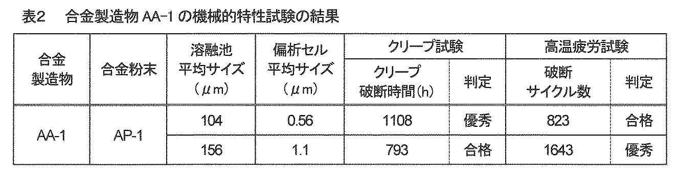
表2に示したように、AA-1において、偏析セルの平均サイズが比較的小さい第1領域は、クリープ特性が「優秀」であり高温疲労特性が「合格」と判定される。一方、偏析セルの平均サイズが比較的大きい第2領域は、クリープ特性が「合格」であり高温疲労特性が「優秀」と判定される。第2領域は、第1領域に対してクリープ特性が約28%減少したが、高温疲労特性が約100%増加している。
As shown in Table 2, in AA-1, in the first region where the average size of the segregated cells is relatively small, the creep characteristic is "excellent" and the high temperature fatigue characteristic is judged to be "pass". On the other hand, in the second region where the average size of the segregated cell is relatively large, the creep characteristic is "passed" and the high temperature fatigue characteristic is determined to be "excellent". In the second region, the creep characteristics are reduced by about 28% with respect to the first region, but the high temperature fatigue characteristics are increased by about 100%.
AA-2およびAA-3においても同傾向の機械的特性が測定されることを別途確認した。これら機械的特性試験の結果から、本発明のCo基合金製造物は、1つの部材の中で部位によって性状を調製できることが確認される。
It was separately confirmed that the same tendency of mechanical characteristics was measured in AA-2 and AA-3. From the results of these mechanical property tests, it is confirmed that the Co-based alloy product of the present invention can be adjusted in properties depending on the site in one member.
なお、金属材料では、一般的に、結晶粒の大きさが小さくなるほどクリープ強度が低く疲労特性が高いとされている。これは、個々の結晶粒が小さくなると、各結晶粒界でのわずかな滑りが合算されることで物品全体として大きな滑りになること、物品全体に対する所定のひずみ量に対して各結晶粒が受け持つ実効的なひずみ量が小さくなること、および結晶粒界の絶対量が増加してそれによって亀裂の進展が抑制されることが複合的に関与しているため、と考えられている。
In metal materials, it is generally said that the smaller the crystal grain size, the lower the creep strength and the higher the fatigue characteristics. This is because when the individual crystal grains become smaller, the slight slips at the grain boundaries are added up to result in a large slip for the entire article, and each crystal grain is responsible for a predetermined strain amount for the entire article. It is believed that this is because the effective strain amount is reduced and the absolute amount of grain boundaries is increased, thereby suppressing the growth of cracks.
本発明の合金製造物における偏析セルの境界領域と結晶粒界とは同義ではないものの、上記の機械的特性の結果は、従来の技術常識では単純に説明できない極めて特異的な現象であると言える。
Although the boundary region of the segregated cell and the grain boundary in the alloy product of the present invention are not synonymous, it can be said that the result of the above mechanical properties is an extremely specific phenomenon that cannot be simply explained by the conventional common general technical knowledge. ..
[実験6]
(酸化試験)
耐酸化特性は、クリープ特性を優先する第1領域で重要な特性と考えられることから、AA-1~AA-3から第1領域のみを採取して試験片とした。酸化試験は、大気中で950℃に昇温して、500時間保持ごとに試験片の質量変化率を測定した。 [Experiment 6]
(Oxidation test)
Since the oxidation resistance property is considered to be an important property in the first region where the creep property is prioritized, only the first region from AA-1 to AA-3 was sampled and used as a test piece. In the oxidation test, the temperature was raised to 950 ° C. in the atmosphere, and the mass change rate of the test piece was measured every 500 hours of holding.
ここで言う質量変化率とは、試験片の当該保持時間における質量を初期質量で除したものと定義する。酸化試験によって試験片が酸化すると、酸化皮膜が形成される分の質量変化率の増加が観測されるはずである。
The mass change rate referred to here is defined as the mass of the test piece at the relevant holding time divided by the initial mass. When the test piece is oxidized by the oxidation test, an increase in the mass change rate should be observed as the oxide film is formed.
図9は、合金製造物AA-2およびAA-3の酸化試験における保持時間と質量変化率との関係を示すグラフである。図9に示したように、AA-2は、時間の経過と共に質量変化率が単調増加している(例えば、1000時間保持の質量変化率が500時間保持のそれよりも大きくなっている)。一方、AA-3は、500時間の辺りで質量変化率が極大値を示した後、質量変化率が減少している(1000時間保持の質量変化率が500時間保持のそれよりも小さくなっている)。また、図示は省略したが、AA-1は、AA-2と同様の結果を示した。
FIG. 9 is a graph showing the relationship between the retention time and the mass change rate in the oxidation test of the alloy products AA-2 and AA-3. As shown in FIG. 9, the mass change rate of AA-2 increases monotonically with the passage of time (for example, the mass change rate of 1000 hours holding is larger than that of 500 hours holding). On the other hand, in AA-3, the mass change rate showed a maximum value around 500 hours, and then the mass change rate decreased (the mass change rate of 1000 hours holding became smaller than that of 500 hours holding). Yes). Although not shown, AA-1 showed the same results as AA-2.
酸化試験において質量変化率が極大値を示した後に減少することは、酸化皮膜の形成と剥離・脱落との競合において、形成よりも剥離・脱落の方が多いことを意味する。これは、高温部材における酸化減肉につながる。耐酸化特性の観点からは、酸化減肉が少ない方が望ましい。
The decrease after the mass change rate reaches the maximum value in the oxidation test means that there are more peeling / falling than the formation in the competition between the formation of the oxide film and the peeling / falling. This leads to oxidative thinning in high temperature members. From the viewpoint of oxidation resistance, it is desirable that there is little oxidative thinning.
酸化試験の結果から、特許文献1よりも高Al含有率や高N含有率を有するAA-1~AA-2は、AA-3よりも耐酸化特性に優れると言える。なお、Co基合金材料は、もともと耐酸化性に優れることから、AA-3であっても析出強化Ni基合金材料よりも優れた耐酸化性を有していると言える。
From the results of the oxidation test, it can be said that AA-1 to AA-2, which have a higher Al content and a higher N content than Patent Document 1, have better oxidation resistance than AA-3. Since the Co-based alloy material is originally excellent in oxidation resistance, it can be said that even AA-3 has better oxidation resistance than the precipitation-strengthened Ni-based alloy material.
酸化試験を終えた試験片の横断面をSEM観察したところ、図8と同様の微細組織を有していることが確認された。言い換えると、ひずみ緩和アニール工程S3を行っていない合金製造物をそのまま高温部材として使用した場合であっても、使用環境の温度がひずみ緩和アニールの温度条件と同等であると、使用に伴って工程S3を行った場合と同じ状態になることが確認された。
When the cross section of the test piece after the oxidation test was observed by SEM, it was confirmed that it had the same microstructure as in FIG. In other words, even when the alloy product not subjected to the strain relaxation annealing step S3 is used as it is as a high temperature member, if the temperature of the usage environment is equivalent to the temperature condition of the strain relaxation annealing, the step is accompanied by use. It was confirmed that the condition was the same as when S3 was performed.
上述した実施形態や実験例は、本発明の理解を助けるために説明したものであり、本発明は、記載した具体的な構成のみに限定されるものではない。例えば、実施形態の構成の一部を当業者の技術常識の構成に置き換えることが可能であり、また、実施形態の構成に当業者の技術常識の構成を加えることも可能である。すなわち、本発明は、本明細書の実施形態や実験例の構成の一部について、発明の技術的思想を逸脱しない範囲で、削除・他の構成に置換・他の構成の追加をすることが可能である。
The above-described embodiments and experimental examples have been described for the purpose of assisting the understanding of the present invention, and the present invention is not limited to the specific configuration described. For example, it is possible to replace a part of the configuration of the embodiment with the configuration of the common general technical knowledge of those skilled in the art, and it is also possible to add the configuration of the common general technical knowledge of those skilled in the art to the configuration of the embodiment. That is, the present invention may delete, replace with another configuration, or add another configuration to a part of the configurations of the embodiments and experimental examples of the present specification without departing from the technical idea of the invention. It is possible.
100…タービン動翼、110…翼部、120…シャンク部、121…プラットホーム、122…ラジアルフィン、130…ルート部、200…タービン静翼、210…翼部、220…内輪側エンドウォール、230…外輪側エンドウォール、300…ガスタービン、310…圧縮機部、320…タービン部、321…タービンノズル、400…熱交換器、410…セパレート層、420…フィン層、430…サイドバー部。
100 ... Turbine moving wing, 110 ... Wing part, 120 ... Shank part, 121 ... Platform, 122 ... Radial fin, 130 ... Root part, 200 ... Turbine stationary wing, 210 ... Wing part, 220 ... Inner ring side end wall, 230 ... Outer ring side end wall, 300 ... gas turbine, 310 ... compressor section, 320 ... turbine section, 321 ... turbine nozzle, 400 ... heat exchanger, 410 ... separate layer, 420 ... fin layer, 430 ... sidebar section.
Claims (11)
- コバルト基合金材料からなる製造物であって、
前記コバルト基合金材料は、
0.08質量%以上0.25質量%以下の炭素と、
0.003質量%以上0.2質量%以下の窒素とを含み、前記炭素および前記窒素の合計が0.083質量%以上0.28質量%以下であり、
0.1質量%以下のホウ素と、
10質量%以上30質量%以下のクロムとを含み、
鉄を5質量%以下でニッケルを30質量%以下で含み、前記鉄および前記ニッケルの合計が30質量%以下であり、
タングステンおよび/またはモリブデンを含み、前記タングステンおよび前記モリブデンの合計が5質量%以上12質量%以下であり、
3質量%以下のアルミニウムと、
0.5質量%以下のケイ素と、
0.5質量%以下のマンガンとを含み、
タングステンおよびモリブデン以外の遷移金属で原子半径が130 pm超のM成分を0.5質量%以上4質量%以下で含み、
残部がコバルトと不純物とからなり、
前記不純物は、0.04質量%以下の酸素を含む、化学組成を有し、
前記製造物は、母相結晶粒の多結晶体であり、
前記母相結晶粒の中には、前記M成分が境界領域に偏析している偏析セルが形成しており、
前記製造物は、前記偏析セルの平均サイズが互いに異なる第1領域および第2領域が存在し、前記第1領域における前記偏析セルの平均サイズが0.13μm以上1.3μm以下の範囲内にあり、前記第2領域における前記偏析セルの平均サイズが0.25μm以上2μm以下の範囲内にあり、前記第1領域における前記偏析セルの平均サイズに対する前記第2領域における前記偏析セルの平均サイズの比が1.3以上である、または
前記母相結晶粒の中には、前記M成分を含むMC型炭化物相、M(C,N)型炭窒化物相および/またはMN型窒化物相の粒子が境界領域に沿って分散析出しているポスト偏析セルが形成しており、
前記製造物は、前記ポスト偏析セルの平均サイズが互いに異なる第1’領域および第2’領域が存在し、前記第1’領域における前記ポスト偏析セルの平均サイズが0.13μm以上1.3μm以下の範囲内にあり、前記第2’領域における前記ポスト偏析セルの平均サイズが0.25μm以上2μm以下の範囲内にあり、前記第1’領域における前記ポスト偏析セルの平均サイズに対する前記第2’領域における前記ポスト偏析セルの平均サイズの比が1.3以上である、
ことを特徴とするコバルト基合金製造物。 A product made of a cobalt-based alloy material
The cobalt-based alloy material is
With carbon of 0.08% by mass or more and 0.25% by mass or less,
It contains 0.003% by mass or more and 0.2% by mass or less of nitrogen, and the total of the carbon and the nitrogen is 0.083% by mass or more and 0.28% by mass or less.
Boron of 0.1% by mass or less and
Contains 10% by mass or more and 30% by mass or less of chromium
It contains 5% by mass or less of iron and 30% by mass or less of nickel, and the total of the iron and the nickel is 30% by mass or less.
It contains tungsten and / or molybdenum, and the total of the tungsten and the molybdenum is 5% by mass or more and 12% by mass or less.
With 3% by mass or less of aluminum,
With 0.5% by mass or less of silicon,
Contains less than 0.5% by weight of manganese
A transition metal other than tungsten and molybdenum containing an M component with an atomic radius of more than 130 pm in an amount of 0.5% by mass or more and 4% by mass or less.
The rest consists of cobalt and impurities,
The impurities have a chemical composition containing 0.04% by weight or less of oxygen and have a chemical composition.
The product is a polycrystal of parent phase crystal grains.
Segregation cells in which the M component is segregated in the boundary region are formed in the parent phase crystal grains.
The product has a first region and a second region in which the average sizes of the segregated cells are different from each other, and the average size of the segregated cells in the first region is within the range of 0.13 μm or more and 1.3 μm or less. The average size of the segregated cells in the second region is within the range of 0.25 μm or more and 2 μm or less, and the ratio of the average size of the segregated cells in the second region to the average size of the segregated cells in the first region is 1.3 or more. Or, in the parent phase crystal grains, particles of the MC type carbide phase, the M (C, N) type carbon dioxide phase and / or the MN type nitride phase containing the M component are along the boundary region. Post-segregation cells that are dispersed and precipitated are formed.
The product has a first'region and a second'region in which the average sizes of the post segregated cells are different from each other, and the average size of the post segregated cells in the first'region is in the range of 0.13 μm or more and 1.3 μm or less. The average size of the post-segregated cell in the 2'region is within the range of 0.25 μm or more and 2 μm or less, and the said in the 2'region with respect to the average size of the post-segregated cell in the 1'region. The average size ratio of post-segregated cells is 1.3 or higher,
A cobalt-based alloy product characterized by this. - 請求項1に記載のコバルト基合金製造物において、
前記化学組成の前記M成分は、チタン、ジルコニウム、ハフニウム、バナジウム、ニオブおよびタンタルのうちの1種以上であることを特徴とするコバルト基合金製造物。 In the cobalt-based alloy product according to claim 1,
A cobalt-based alloy product, wherein the M component having the chemical composition is one or more of titanium, zirconium, hafnium, vanadium, niobium and tantalum. - 請求項2に記載のコバルト基合金製造物において、
前記化学組成の前記M成分は、
前記チタンを含む場合、該チタンは0.01質量%以上1質量%以下であり、
前記ジルコニウムを含む場合、該ジルコニウムは0.05質量%以上1.5質量%以下であり、
前記ハフニウムを含む場合、該ハフニウムは0.01質量%以上0.5質量%以下であり、
前記バナジウムを含む場合、該バナジウムは0.01質量%以上0.5質量%以下であり、
前記ニオブを含む場合、該ニオブは0.02質量%以上1質量%以下であり、
前記タンタルを含む場合、該タンタルは0.05質量%以上1.5質量%以下である、
ことを特徴とするコバルト基合金製造物。 In the cobalt-based alloy product according to claim 2.
The M component of the chemical composition is
When the titanium is contained, the titanium is 0.01% by mass or more and 1% by mass or less.
When the zirconium is contained, the zirconium is 0.05% by mass or more and 1.5% by mass or less.
When the hafnium is contained, the hafnium is 0.01% by mass or more and 0.5% by mass or less.
When the vanadium is contained, the vanadium is 0.01% by mass or more and 0.5% by mass or less.
When the niobium is contained, the niobium is 0.02% by mass or more and 1% by mass or less.
When the tantalum is contained, the tantalum is 0.05% by mass or more and 1.5% by mass or less.
A cobalt-based alloy product characterized by this. - 請求項2又は請求項3に記載のコバルト基合金製造物において、
前記化学組成の前記M成分は、
前記ジルコニウムを必須とすることを特徴とするコバルト基合金製造物。 In the cobalt-based alloy product according to claim 2 or 3.
The M component of the chemical composition is
A cobalt-based alloy product characterized by requiring zirconium. - 請求項2又は請求項3に記載のコバルト基合金製造物において、
前記化学組成の前記M成分は、
前記チタン、前記ジルコニウム、前記ハフニウム、前記バナジウム、前記ニオブおよび前記タンタルのうちの3種以上であることを特徴とするコバルト基合金製造物。 In the cobalt-based alloy product according to claim 2 or 3.
The M component of the chemical composition is
A cobalt-based alloy product comprising three or more of the titanium, the zirconium, the hafnium, the vanadium, the niobium, and the tantalum. - 請求項1乃至請求項5のいずれか一項に記載のコバルト基合金製造物において、
前記製造物は、温度850℃および応力156 MPaの条件下でクリープ試験を行った場合のクリープ破断時間が1000時間以上である領域と、
温度800℃およびひずみ量1%の条件下で高温疲労試験を行った場合の破断サイクル数が1000サイクル以上である領域とを有することを特徴とするコバルト基合金製造物。 In the cobalt-based alloy product according to any one of claims 1 to 5.
The product has a region where the creep rupture time is 1000 hours or more when the creep test is performed under the conditions of a temperature of 850 ° C. and a stress of 156 MPa.
A cobalt-based alloy product characterized by having a region where the number of fracture cycles is 1000 cycles or more when a high-temperature fatigue test is performed under the conditions of a temperature of 800 ° C. and a strain amount of 1%. - 請求項1乃至請求項6のいずれか一項に記載のコバルト基合金製造物において、
前記第1領域と前記第2領域との間に、該第1領域における前記平均サイズと該第2領域における前記平均サイズとの中間の平均サイズの前記偏析セルが形成された第3領域が更に存在する、または
前記第1’領域と前記第2’領域との間に、該第1’領域における前記平均サイズと該第2’領域における前記平均サイズとの中間の平均サイズの前記ポスト偏析セルが形成された第3’領域が更に存在することを特徴とするコバルト基合金製造物。 In the cobalt-based alloy product according to any one of claims 1 to 6.
A third region in which the segregated cell having an average size intermediate between the average size in the first region and the average size in the second region is formed between the first region and the second region is further formed. The post-segregation cell that exists or has an average size between the 1'region and the 2'region that is intermediate between the average size in the 1'region and the average size in the 2'region. A cobalt-based alloy product, characterized in that there is a further 3'region in which the is formed. - 請求項1乃至請求項7のいずれか一項に記載のコバルト基合金製造物において、
前記製造物は、高温部材であることを特徴とするコバルト基合金製造物。 In the cobalt-based alloy product according to any one of claims 1 to 7.
The product is a cobalt-based alloy product characterized by being a high-temperature member. - 請求項8に記載のコバルト基合金製造物において、
前記高温部材は、タービン静翼、タービン動翼、タービン燃焼器ノズルまたは熱交換器であることを特徴とするコバルト基合金製造物。 In the cobalt-based alloy product according to claim 8.
A cobalt-based alloy product, wherein the high temperature member is a turbine blade, a turbine blade, a turbine combustor nozzle, or a heat exchanger. - 請求項1乃至請求項9のいずれか一項に記載のコバルト基合金製造物の製造方法であって、
前記化学組成を有するコバルト基合金粉末を用意する合金粉末用意工程と、
前記コバルト基合金粉末を敷き詰めて所定厚さの合金粉末床を用意する合金粉末床用意素工程と、前記合金粉末床の所定の領域にレーザ光を照射して該領域の前記コバルト基合金粉末を局所溶融・急速凝固させるレーザ溶融凝固素工程と、を繰り返して付加造形体を形成する選択的レーザ溶融工程とを有し、
前記選択的レーザ溶融工程は、前記合金粉末床の前記所定厚さh(単位:μm)と前記レーザ光の出力P(単位:W)と前記レーザ光の走査速度S(単位:mm/s)との関係が「15 <h< 150」かつ「67(P/S)-3.5 <h< 2222(P/S)+13」を満たすように、前記所定厚さhと前記出力Pと前記走査速度Sとを制御するものであり、前記第2領域を付加造形する際の溶融池の平均サイズが前記第1領域を付加造形する際のそれよりも大きくなるように制御する、
ことを特徴とするコバルト基合金製造物の製造方法。 The method for producing a cobalt-based alloy product according to any one of claims 1 to 9.
An alloy powder preparation step for preparing a cobalt-based alloy powder having the above chemical composition, and
An alloy powder bed preparation step of spreading the cobalt-based alloy powder to prepare an alloy powder bed of a predetermined thickness, and irradiating a predetermined region of the alloy powder bed with laser light to obtain the cobalt-based alloy powder in the region. It has a laser melt coagulation element step for local melting and rapid solidification, and a selective laser melting step for forming an additional model by repeating the steps.
In the selective laser melting step, the predetermined thickness h (unit: μm) of the alloy powder bed, the output P (unit: W) of the laser beam, and the scanning speed S (unit: mm / s) of the laser beam are performed. The predetermined thickness h, the output P, and the scanning speed so that the relationship with the above satisfies "15 <h <150" and "67 (P / S) -3.5 <h <2222 (P / S) +13". S is controlled, and the average size of the molten pool when the second region is additionally formed is controlled to be larger than that when the first region is additionally formed.
A method for manufacturing a cobalt-based alloy product. - 請求項10に記載のコバルト基合金製造物の製造方法において、
前記選択的レーザ溶融工程の後に、前記付加造形体に対して残留内部ひずみを緩和するために600℃以上1100℃未満の温度範囲のアニールを施すひずみ緩和アニール工程を更に有することを特徴とするコバルト基合金製造物の製造方法。 In the method for producing a cobalt-based alloy product according to claim 10.
Cobalt further comprising a strain relaxation annealing step of annealing the additional shaped body in a temperature range of 600 ° C. or higher and lower than 1100 ° C. in order to relax the residual internal strain after the selective laser melting step. Manufacturing method of base alloy product.
Priority Applications (7)
| Application Number | Priority Date | Filing Date | Title |
|---|---|---|---|
| EP20920766.1A EP4006188A4 (en) | 2020-09-04 | 2020-09-04 | Cobalt-based alloy product and method for producing same |
| KR1020217030429A KR20220031991A (en) | 2020-09-04 | 2020-09-04 | Cobalt-based alloy product and method for manufacturing the same |
| CN202080026978.9A CN114466945A (en) | 2020-09-04 | 2020-09-04 | Cobalt-based alloy product and method for producing same |
| US17/599,692 US20220220584A1 (en) | 2020-09-04 | 2020-09-04 | Cobalt based alloy product and method for manufacturing same |
| PCT/JP2020/033547 WO2022049717A1 (en) | 2020-09-04 | 2020-09-04 | Cobalt-based alloy product and method for producing same |
| JP2021564517A JP7223878B2 (en) | 2020-09-04 | 2020-09-04 | Cobalt-based alloy product and manufacturing method thereof |
| TW110131612A TWI778764B (en) | 2020-09-04 | 2021-08-26 | Cobalt alloy product and method for producing the same |
Applications Claiming Priority (1)
| Application Number | Priority Date | Filing Date | Title |
|---|---|---|---|
| PCT/JP2020/033547 WO2022049717A1 (en) | 2020-09-04 | 2020-09-04 | Cobalt-based alloy product and method for producing same |
Publications (1)
| Publication Number | Publication Date |
|---|---|
| WO2022049717A1 true WO2022049717A1 (en) | 2022-03-10 |
Family
ID=80491857
Family Applications (1)
| Application Number | Title | Priority Date | Filing Date |
|---|---|---|---|
| PCT/JP2020/033547 WO2022049717A1 (en) | 2020-09-04 | 2020-09-04 | Cobalt-based alloy product and method for producing same |
Country Status (7)
| Country | Link |
|---|---|
| US (1) | US20220220584A1 (en) |
| EP (1) | EP4006188A4 (en) |
| JP (1) | JP7223878B2 (en) |
| KR (1) | KR20220031991A (en) |
| CN (1) | CN114466945A (en) |
| TW (1) | TWI778764B (en) |
| WO (1) | WO2022049717A1 (en) |
Families Citing this family (2)
| Publication number | Priority date | Publication date | Assignee | Title |
|---|---|---|---|---|
| US20210381084A1 (en) * | 2019-12-26 | 2021-12-09 | Mitsubishi Power, Ltd. | Cobalt based alloy product |
| JP7223877B2 (en) * | 2020-09-04 | 2023-02-16 | 三菱重工業株式会社 | Cobalt-based alloy materials and cobalt-based alloy products |
Citations (6)
| Publication number | Priority date | Publication date | Assignee | Title |
|---|---|---|---|---|
| JPS6311638A (en) * | 1986-03-20 | 1988-01-19 | Hitachi Ltd | Cobalt-base alloy having high strength and high toughness and its production |
| JPH029290B2 (en) | 1981-03-31 | 1990-03-01 | Tokyo Shibaura Electric Co | |
| JP2016102257A (en) * | 2014-11-28 | 2016-06-02 | ゼネラル エレクトリック テクノロジー ゲゼルシャフト ミット ベシュレンクテル ハフツングGeneral Electric Technology GmbH | Method for manufacturing component using additive manufacturing method |
| JP2017145483A (en) * | 2016-02-19 | 2017-08-24 | セイコーエプソン株式会社 | Metal powder for powder metallurgy, compound, granulated powder, sintered body and heat-resistant component |
| JP2019049022A (en) * | 2017-09-08 | 2019-03-28 | 三菱日立パワーシステムズ株式会社 | Cobalt group alloy laminated shaped body, cobalt group alloy product, and method for manufacturing them |
| JP2019173175A (en) * | 2019-04-02 | 2019-10-10 | 三菱日立パワーシステムズ株式会社 | Manufacturing method of cobalt-based alloy laminate molded body |
Family Cites Families (4)
| Publication number | Priority date | Publication date | Assignee | Title |
|---|---|---|---|---|
| JPH029290Y2 (en) | 1985-06-13 | 1990-03-07 | ||
| EP2865465B1 (en) * | 2013-09-27 | 2018-01-17 | Ansaldo Energia IP UK Limited | Method for manufacturing a metallic component by additive laser manufacturing |
| TWI668310B (en) * | 2018-03-01 | 2019-08-11 | 國家中山科學研究院 | Superalloy material for laminate manufacturing |
| AU2018422117B2 (en) * | 2018-12-10 | 2021-06-03 | Mitsubishi Power, Ltd. | Cobalt based alloy additive manufactured article, cobalt based alloy product, and method for manufacturing same |
-
2020
- 2020-09-04 CN CN202080026978.9A patent/CN114466945A/en active Pending
- 2020-09-04 JP JP2021564517A patent/JP7223878B2/en active Active
- 2020-09-04 KR KR1020217030429A patent/KR20220031991A/en active IP Right Grant
- 2020-09-04 WO PCT/JP2020/033547 patent/WO2022049717A1/en unknown
- 2020-09-04 EP EP20920766.1A patent/EP4006188A4/en not_active Withdrawn
- 2020-09-04 US US17/599,692 patent/US20220220584A1/en not_active Abandoned
-
2021
- 2021-08-26 TW TW110131612A patent/TWI778764B/en active
Patent Citations (6)
| Publication number | Priority date | Publication date | Assignee | Title |
|---|---|---|---|---|
| JPH029290B2 (en) | 1981-03-31 | 1990-03-01 | Tokyo Shibaura Electric Co | |
| JPS6311638A (en) * | 1986-03-20 | 1988-01-19 | Hitachi Ltd | Cobalt-base alloy having high strength and high toughness and its production |
| JP2016102257A (en) * | 2014-11-28 | 2016-06-02 | ゼネラル エレクトリック テクノロジー ゲゼルシャフト ミット ベシュレンクテル ハフツングGeneral Electric Technology GmbH | Method for manufacturing component using additive manufacturing method |
| JP2017145483A (en) * | 2016-02-19 | 2017-08-24 | セイコーエプソン株式会社 | Metal powder for powder metallurgy, compound, granulated powder, sintered body and heat-resistant component |
| JP2019049022A (en) * | 2017-09-08 | 2019-03-28 | 三菱日立パワーシステムズ株式会社 | Cobalt group alloy laminated shaped body, cobalt group alloy product, and method for manufacturing them |
| JP2019173175A (en) * | 2019-04-02 | 2019-10-10 | 三菱日立パワーシステムズ株式会社 | Manufacturing method of cobalt-based alloy laminate molded body |
Non-Patent Citations (1)
| Title |
|---|
| See also references of EP4006188A4 |
Also Published As
| Publication number | Publication date |
|---|---|
| EP4006188A4 (en) | 2023-05-03 |
| KR20220031991A (en) | 2022-03-15 |
| TW202217016A (en) | 2022-05-01 |
| TWI778764B (en) | 2022-09-21 |
| EP4006188A1 (en) | 2022-06-01 |
| JP7223878B2 (en) | 2023-02-16 |
| JPWO2022049717A1 (en) | 2022-03-10 |
| US20220220584A1 (en) | 2022-07-14 |
| CN114466945A (en) | 2022-05-10 |
Similar Documents
| Publication | Publication Date | Title |
|---|---|---|
| RU2703670C9 (en) | Cobalt based alloy additive manufactured article, cobalt based alloy product, and method for manufacturing same | |
| JP7076581B2 (en) | Cobalt-based alloy product | |
| JP6935579B2 (en) | Cobalt-based alloy product and method for manufacturing the product | |
| JP6935578B2 (en) | Cobalt-based alloy product | |
| JP6935580B2 (en) | Cobalt-based alloy product and its manufacturing method | |
| JP6935577B2 (en) | Cobalt-based alloy product | |
| WO2020179085A1 (en) | Heat exchanger | |
| WO2022049717A1 (en) | Cobalt-based alloy product and method for producing same | |
| WO2022049716A1 (en) | Cobalt-based alloy material and cobalt-based alloy product | |
| JP2023105829A (en) | Cobalt-based alloy material and cobalt-based alloy product |
Legal Events
| Date | Code | Title | Description |
|---|---|---|---|
| ENP | Entry into the national phase |
Ref document number: 2021564517 Country of ref document: JP Kind code of ref document: A |
|
| ENP | Entry into the national phase |
Ref document number: 2020920766 Country of ref document: EP Effective date: 20210902 |
|
| NENP | Non-entry into the national phase |
Ref country code: DE |