WO2022045967A1 - Hydrogels and methods of fabrication thereof - Google Patents
Hydrogels and methods of fabrication thereof Download PDFInfo
- Publication number
- WO2022045967A1 WO2022045967A1 PCT/SG2021/050468 SG2021050468W WO2022045967A1 WO 2022045967 A1 WO2022045967 A1 WO 2022045967A1 SG 2021050468 W SG2021050468 W SG 2021050468W WO 2022045967 A1 WO2022045967 A1 WO 2022045967A1
- Authority
- WO
- WIPO (PCT)
- Prior art keywords
- hydrogel
- chitosan
- wound
- ink
- printed
- Prior art date
- Legal status (The legal status is an assumption and is not a legal conclusion. Google has not performed a legal analysis and makes no representation as to the accuracy of the status listed.)
- Ceased
Links
Classifications
-
- A—HUMAN NECESSITIES
- A61—MEDICAL OR VETERINARY SCIENCE; HYGIENE
- A61P—SPECIFIC THERAPEUTIC ACTIVITY OF CHEMICAL COMPOUNDS OR MEDICINAL PREPARATIONS
- A61P17/00—Drugs for dermatological disorders
- A61P17/02—Drugs for dermatological disorders for treating wounds, ulcers, burns, scars, keloids, or the like
-
- A—HUMAN NECESSITIES
- A61—MEDICAL OR VETERINARY SCIENCE; HYGIENE
- A61L—METHODS OR APPARATUS FOR STERILISING MATERIALS OR OBJECTS IN GENERAL; DISINFECTION, STERILISATION OR DEODORISATION OF AIR; CHEMICAL ASPECTS OF BANDAGES, DRESSINGS, ABSORBENT PADS OR SURGICAL ARTICLES; MATERIALS FOR BANDAGES, DRESSINGS, ABSORBENT PADS OR SURGICAL ARTICLES
- A61L15/00—Chemical aspects of, or use of materials for, bandages, dressings or absorbent pads
- A61L15/16—Bandages, dressings or absorbent pads for physiological fluids such as urine or blood, e.g. sanitary towels, tampons
- A61L15/22—Bandages, dressings or absorbent pads for physiological fluids such as urine or blood, e.g. sanitary towels, tampons containing macromolecular materials
- A61L15/28—Polysaccharides or their derivatives
-
- A—HUMAN NECESSITIES
- A61—MEDICAL OR VETERINARY SCIENCE; HYGIENE
- A61L—METHODS OR APPARATUS FOR STERILISING MATERIALS OR OBJECTS IN GENERAL; DISINFECTION, STERILISATION OR DEODORISATION OF AIR; CHEMICAL ASPECTS OF BANDAGES, DRESSINGS, ABSORBENT PADS OR SURGICAL ARTICLES; MATERIALS FOR BANDAGES, DRESSINGS, ABSORBENT PADS OR SURGICAL ARTICLES
- A61L15/00—Chemical aspects of, or use of materials for, bandages, dressings or absorbent pads
- A61L15/16—Bandages, dressings or absorbent pads for physiological fluids such as urine or blood, e.g. sanitary towels, tampons
- A61L15/42—Use of materials characterised by their function or physical properties
- A61L15/44—Medicaments
-
- A—HUMAN NECESSITIES
- A61—MEDICAL OR VETERINARY SCIENCE; HYGIENE
- A61L—METHODS OR APPARATUS FOR STERILISING MATERIALS OR OBJECTS IN GENERAL; DISINFECTION, STERILISATION OR DEODORISATION OF AIR; CHEMICAL ASPECTS OF BANDAGES, DRESSINGS, ABSORBENT PADS OR SURGICAL ARTICLES; MATERIALS FOR BANDAGES, DRESSINGS, ABSORBENT PADS OR SURGICAL ARTICLES
- A61L15/00—Chemical aspects of, or use of materials for, bandages, dressings or absorbent pads
- A61L15/16—Bandages, dressings or absorbent pads for physiological fluids such as urine or blood, e.g. sanitary towels, tampons
- A61L15/42—Use of materials characterised by their function or physical properties
- A61L15/46—Deodorants or malodour counteractants, e.g. to inhibit the formation of ammonia or bacteria
-
- B—PERFORMING OPERATIONS; TRANSPORTING
- B29—WORKING OF PLASTICS; WORKING OF SUBSTANCES IN A PLASTIC STATE IN GENERAL
- B29C—SHAPING OR JOINING OF PLASTICS; SHAPING OF MATERIAL IN A PLASTIC STATE, NOT OTHERWISE PROVIDED FOR; AFTER-TREATMENT OF THE SHAPED PRODUCTS, e.g. REPAIRING
- B29C64/00—Additive manufacturing, i.e. manufacturing of three-dimensional [3D] objects by additive deposition, additive agglomeration or additive layering, e.g. by 3D printing, stereolithography or selective laser sintering
- B29C64/10—Processes of additive manufacturing
- B29C64/106—Processes of additive manufacturing using only liquids or viscous materials, e.g. depositing a continuous bead of viscous material
-
- B—PERFORMING OPERATIONS; TRANSPORTING
- B33—ADDITIVE MANUFACTURING TECHNOLOGY
- B33Y—ADDITIVE MANUFACTURING, i.e. MANUFACTURING OF THREE-DIMENSIONAL [3D] OBJECTS BY ADDITIVE DEPOSITION, ADDITIVE AGGLOMERATION OR ADDITIVE LAYERING, e.g. BY 3D PRINTING, STEREOLITHOGRAPHY OR SELECTIVE LASER SINTERING
- B33Y10/00—Processes of additive manufacturing
-
- B—PERFORMING OPERATIONS; TRANSPORTING
- B33—ADDITIVE MANUFACTURING TECHNOLOGY
- B33Y—ADDITIVE MANUFACTURING, i.e. MANUFACTURING OF THREE-DIMENSIONAL [3D] OBJECTS BY ADDITIVE DEPOSITION, ADDITIVE AGGLOMERATION OR ADDITIVE LAYERING, e.g. BY 3D PRINTING, STEREOLITHOGRAPHY OR SELECTIVE LASER SINTERING
- B33Y70/00—Materials specially adapted for additive manufacturing
-
- B—PERFORMING OPERATIONS; TRANSPORTING
- B33—ADDITIVE MANUFACTURING TECHNOLOGY
- B33Y—ADDITIVE MANUFACTURING, i.e. MANUFACTURING OF THREE-DIMENSIONAL [3D] OBJECTS BY ADDITIVE DEPOSITION, ADDITIVE AGGLOMERATION OR ADDITIVE LAYERING, e.g. BY 3D PRINTING, STEREOLITHOGRAPHY OR SELECTIVE LASER SINTERING
- B33Y80/00—Products made by additive manufacturing
-
- C—CHEMISTRY; METALLURGY
- C08—ORGANIC MACROMOLECULAR COMPOUNDS; THEIR PREPARATION OR CHEMICAL WORKING-UP; COMPOSITIONS BASED THEREON
- C08J—WORKING-UP; GENERAL PROCESSES OF COMPOUNDING; AFTER-TREATMENT NOT COVERED BY SUBCLASSES C08B, C08C, C08F, C08G or C08H
- C08J3/00—Processes of treating or compounding macromolecular substances
- C08J3/02—Making solutions, dispersions, lattices or gels by other methods than by solution, emulsion or suspension polymerisation techniques
- C08J3/03—Making solutions, dispersions, lattices or gels by other methods than by solution, emulsion or suspension polymerisation techniques in aqueous media
- C08J3/075—Macromolecular gels
-
- A—HUMAN NECESSITIES
- A61—MEDICAL OR VETERINARY SCIENCE; HYGIENE
- A61K—PREPARATIONS FOR MEDICAL, DENTAL OR TOILETRY PURPOSES
- A61K9/00—Medicinal preparations characterised by special physical form
- A61K9/70—Web, sheet or filament bases ; Films; Fibres of the matrix type containing drug
-
- A—HUMAN NECESSITIES
- A61—MEDICAL OR VETERINARY SCIENCE; HYGIENE
- A61L—METHODS OR APPARATUS FOR STERILISING MATERIALS OR OBJECTS IN GENERAL; DISINFECTION, STERILISATION OR DEODORISATION OF AIR; CHEMICAL ASPECTS OF BANDAGES, DRESSINGS, ABSORBENT PADS OR SURGICAL ARTICLES; MATERIALS FOR BANDAGES, DRESSINGS, ABSORBENT PADS OR SURGICAL ARTICLES
- A61L2300/00—Biologically active materials used in bandages, wound dressings, absorbent pads or medical devices
- A61L2300/40—Biologically active materials used in bandages, wound dressings, absorbent pads or medical devices characterised by a specific therapeutic activity or mode of action
- A61L2300/402—Anaestetics, analgesics, e.g. lidocaine
-
- A—HUMAN NECESSITIES
- A61—MEDICAL OR VETERINARY SCIENCE; HYGIENE
- A61L—METHODS OR APPARATUS FOR STERILISING MATERIALS OR OBJECTS IN GENERAL; DISINFECTION, STERILISATION OR DEODORISATION OF AIR; CHEMICAL ASPECTS OF BANDAGES, DRESSINGS, ABSORBENT PADS OR SURGICAL ARTICLES; MATERIALS FOR BANDAGES, DRESSINGS, ABSORBENT PADS OR SURGICAL ARTICLES
- A61L2300/00—Biologically active materials used in bandages, wound dressings, absorbent pads or medical devices
- A61L2300/40—Biologically active materials used in bandages, wound dressings, absorbent pads or medical devices characterised by a specific therapeutic activity or mode of action
- A61L2300/404—Biocides, antimicrobial agents, antiseptic agents
- A61L2300/406—Antibiotics
-
- A—HUMAN NECESSITIES
- A61—MEDICAL OR VETERINARY SCIENCE; HYGIENE
- A61L—METHODS OR APPARATUS FOR STERILISING MATERIALS OR OBJECTS IN GENERAL; DISINFECTION, STERILISATION OR DEODORISATION OF AIR; CHEMICAL ASPECTS OF BANDAGES, DRESSINGS, ABSORBENT PADS OR SURGICAL ARTICLES; MATERIALS FOR BANDAGES, DRESSINGS, ABSORBENT PADS OR SURGICAL ARTICLES
- A61L2300/00—Biologically active materials used in bandages, wound dressings, absorbent pads or medical devices
- A61L2300/40—Biologically active materials used in bandages, wound dressings, absorbent pads or medical devices characterised by a specific therapeutic activity or mode of action
- A61L2300/41—Anti-inflammatory agents, e.g. NSAIDs
-
- A—HUMAN NECESSITIES
- A61—MEDICAL OR VETERINARY SCIENCE; HYGIENE
- A61L—METHODS OR APPARATUS FOR STERILISING MATERIALS OR OBJECTS IN GENERAL; DISINFECTION, STERILISATION OR DEODORISATION OF AIR; CHEMICAL ASPECTS OF BANDAGES, DRESSINGS, ABSORBENT PADS OR SURGICAL ARTICLES; MATERIALS FOR BANDAGES, DRESSINGS, ABSORBENT PADS OR SURGICAL ARTICLES
- A61L2300/00—Biologically active materials used in bandages, wound dressings, absorbent pads or medical devices
- A61L2300/40—Biologically active materials used in bandages, wound dressings, absorbent pads or medical devices characterised by a specific therapeutic activity or mode of action
- A61L2300/412—Tissue-regenerating or healing or proliferative agents
- A61L2300/414—Growth factors
-
- A—HUMAN NECESSITIES
- A61—MEDICAL OR VETERINARY SCIENCE; HYGIENE
- A61L—METHODS OR APPARATUS FOR STERILISING MATERIALS OR OBJECTS IN GENERAL; DISINFECTION, STERILISATION OR DEODORISATION OF AIR; CHEMICAL ASPECTS OF BANDAGES, DRESSINGS, ABSORBENT PADS OR SURGICAL ARTICLES; MATERIALS FOR BANDAGES, DRESSINGS, ABSORBENT PADS OR SURGICAL ARTICLES
- A61L2300/00—Biologically active materials used in bandages, wound dressings, absorbent pads or medical devices
- A61L2300/60—Biologically active materials used in bandages, wound dressings, absorbent pads or medical devices characterised by a special physical form
- A61L2300/62—Encapsulated active agents, e.g. emulsified droplets
- A61L2300/624—Nanocapsules
-
- C—CHEMISTRY; METALLURGY
- C08—ORGANIC MACROMOLECULAR COMPOUNDS; THEIR PREPARATION OR CHEMICAL WORKING-UP; COMPOSITIONS BASED THEREON
- C08J—WORKING-UP; GENERAL PROCESSES OF COMPOUNDING; AFTER-TREATMENT NOT COVERED BY SUBCLASSES C08B, C08C, C08F, C08G or C08H
- C08J2305/00—Characterised by the use of polysaccharides or of their derivatives not provided for in groups C08J2301/00 or C08J2303/00
- C08J2305/08—Chitin; Chondroitin sulfate; Hyaluronic acid; Derivatives thereof
Definitions
- the present invention relates, in general terms, to hydrogels and methods of fabrication thereof.
- the present invention also relates to composites comprising the hydrogels as disclosed herein.
- wound dressings Owing to the nature of burns (various shapes, sizes and depths, depending on the duration of exposure and the area of the body exposed to the source) and the limitations of skin grafting, the need for wound dressings to ensure optimal conditions at the wound bed is necessary to minimize bacterial infections and to facilitate wound healing. After grafting, it is also desirable for wound dressings to protect both the donor and recipient sites.
- commercial wound dressings are still sold in fixed shapes that require trimming in order to fit the shape of the patient's wound bed.
- the dosage is fixed and is not always tailored according to the patient's condition.
- the present disclosure relates to a photocrosslinked hydrogel.
- the hydrogel is suitable for use in wound dressings and can be loaded with therapeutic agents.
- the hydrogel can be fabricated on demand following diagnosis via 3D printing for the treatment of thermal burn wounds.
- the fabrication and application of this 3D printed hydrogel wound dressing can be incorporated and integrated into the conventional careflow for burn patients to allow for a higher treatment efficacy and efficiency and can also serve to preserve sterile wound conditions while patients wait for subsequent skin grafting treatment and procedures.
- the present invention provides a method of 3D printing a hydrogel, comprising: a) printing a hydrogel ink on a substrate, the hydrogel ink comprising i) chitosan having a moiety of Formula (I): wherein represents a point of connection to chitosan; and
- Z is optionally substituted alkenyl; and ii) a photoinitiator; and b) crosslinking the hydrogel ink on the substrate in order to form the hydrogel comprising chitosan crosslinked with a moiety of Formula (II):
- X is optionally substituted alkylene; wherein the hydrogel has a degree of crosslinking of more than about 90%.
- the hydrogel is suitable for use as a wound dressing or wound healing material.
- the hydrogel as formed has an appropriate pore size which facilitates the release of excipients or active ingredients from the hydrogel without it being too fast or slow. Further, improved mechanical properties of the hydrogel can be maintained and for the wound dressing to maintain its shape after printing.
- X is optionally substituted Ci-Cs alkylene.
- the moiety of Formula (II) is: wherein represents a point of connection to chitosan.
- the chitosan is characterised by a degree of functionalisation to the moiety of Formula (I) of about 20% to about 90%.
- the hydrogel ink comprises chitosan functionalised with a moiety of Formula (I) at about 1 wt% to about 10 wt% relative to the hydrogel ink.
- the hydrogel ink further comprises a solvent, wherein a weight ratio of the chitosan having a moiety of Formula (I) to the solvent is about 2: 100 to about 20: 100.
- a weight ratio of chitosan to the photoinitiator is about 1:0.08 to about 1:0.3.
- the photoinitiator is selected from lithium phenyl-2,4,6- trimethylbenzoylphosphinate (LAP), 2-Hydroxy-4'-(2-hydroxyethoxy)-2- methylpropiophenone (Irgacure 2959), or a combination thereof.
- LAP lithium phenyl-2,4,6- trimethylbenzoylphosphinate
- Irgacure 2959 2-Hydroxy-4'-(2-hydroxyethoxy)-2- methylpropiophenone
- the hydrogel ink further comprises an excipient and/or active ingredient, a weight ratio of the excipient and/or active ingredient to the hydrogel ink is about 1 %w/w to about 5 %w/w.
- the excipient and/or active ingredient is selected from nanoparticles, microparticles, analgesics, antibiotics, non-steroidal anti-inflammatory drug, growth factor, antiseptic, anti-scarring agent or a combination thereof.
- the excipient and/or active ingredient is selected from lidocaine, levofloxacin, lidocaine encapsulated nanoparticles, levofloxacin encapsulated nanoparticles, cefazolin sodium salt, meropenem trihydrate, polymyxin B sulfate, or a combination thereof.
- the excipient and/or active ingredient is homogenously distributed within the hydrogel.
- excipients and/or active ingredients when at least two excipients and/or active ingredients are present, they are separated from each other such that they form an interface at their boundary.
- the hydrogel is printed as a continuous layer, a grid or as voxels.
- each grid pixel or voxel has an area of about 50 mm 2 to about 300 mm 2 .
- the hydrogel ink has a viscosity of about 0.03 Pa.s to about 60000 Pa.s.
- the viscosity is about 8 Pa.s to about 15 Pa.s at a shear rate of 0.1 s 1 .
- the viscosity is about 0.1 Pa.s to about 1.5 Pa.s at a shear rate of 1000 s 1 .
- the crosslinking (step b) is performed under UV radiation at a wavelength of about 360 nm.
- the crosslinking (step b) is performed for about 1 min to about 5 min.
- the method further comprises a step of hydrating the hydrogel layer.
- the present invention also provides a method of 3D printing a composite for use as a wound dressing, the composite comprising a backing layer and a hydrogel layer, the method comprising: a) printing a substrate in order to form the backing layer; b) printing a hydrogel ink on the backing layer, the hydrogel ink comprising i) chitosan having a moiety of Formula (I): wherein represents a point of connection to chitosan; and
- Z is optionally substituted alkenyl; and ii) a photoinitiator; and c) crosslinking the hydrogel ink on the backing layer in order to form the hydrogel layer comprising chitosan crosslinked with a moiety of Formula (II): wherein represents a point of connection to chitosan; and
- X is optionally substituted alkylene; wherein the hydrogel has a degree of crosslinking of more than about 90%.
- the backing layer comprises a polymer selected from polycaprolactone, poly(lactic acid) (PLA), thermoplastic polyurethane, polyethylene or a combination thereof.
- the method further comprises a step prior to step (a) of providing a wound template for printing the composite.
- the method further comprises printing and crosslinking a barrier layer.
- the barrier layer is formed by printing and crosslinking gelatin methacrylate.
- the method further comprises printing and crosslinking a filler layer.
- the method further comprises printing and crosslinking a second 3D printed hydrogel layer.
- the method further comprises sterilising the hydrogel ink before printing it on the backing layer.
- the hydrogel ink is sterilised using an autoclave.
- the present invention provides a 3D printed hydrogel comprising chitosan crosslinked with a moiety of Formula (II): wherein represents a point of connection to chitosan; and
- X is optionally substituted alkylene; wherein the hydrogel has a degree of crosslinking of more than about 90%.
- the hydrogel has an average pore size of about 5 pm to about 300 pm.
- the hydrogel is characterised by a water content of about 70% to about 200% relative to the hydrogel.
- the hydrogel is characterised by a degradation of about 20 % to about 90% after 3 weeks.
- the present invention also provides a composite, comprising: a) a 3D printed hydrogel layer, the 3D printed hydrogel layer formed from the 3D printed hydrogel as disclosed herein; and b) a backing layer.
- the composite comprises at least two 3D printed hydrogel layers.
- the backing layer is 3D printed.
- the backing layer has a thickness of about 0.5 mm to about 3 mm.
- the backing layer forms a border around the 3D printed hydrogel layer.
- the border has a thickness of about 1 cm to about 5 cm.
- the present invention also provides a hydrogel ink comprising chitosan functionalised with a moiety of Formula (I): wherein represents a point of connection to chitosan; and Z is optionally substituted alkenyl.
- Figure 1 illustrates schematic and pictorial representation of an exemplary composite
- Figure 2 is a flowchart of a method for treating burn wounds
- Figure 3 shows STL images of various hydrogel layers
- Figure 4 shows plots of printing time with respect to area of printed layer
- Figure 5 illustrates a plot of printing time with respect to both thickness and area of the backing layer
- Figure 6 shows STL images of the hydrogel layers with different infill
- Figure 7 shows STL images of the hydrogel layers printed using nozzles of different sizes
- Figure 8 illustrates the effect of using various photoinitiators on the gelation time of chitosan methacrylate
- Figure 9 shows plots of FTIR spectra of various drug loaded hydrogels
- Figure 10 shows plots of UV stability of both Lidocaine and Levofloxacin over exposure time
- Figure 11 shows viscosity plots of hydrogel inks and its moduli before and after photocrosslinking
- Figure 12 shows fluorescent images of 3D printed chitosan methacrylate wound dressings containing Coumarin-6 loaded PLGA nanoparticles
- Figure 13 shows fluorescence intensity of randomly selected fluorescent images from Figure 12;
- FIG. 14 shows Field Emission Scanning Electron Microscopy (FESEM) images of various composite wound dressings
- Figure 15 shows a plot of cumulative release of drugs from chitosan methacrylate wound dressings
- Figure 16 shows a schematic diagram of the preparation of chitosan methacrylate hydrogel inks for the fabrication of wound dressings
- Figure 17 shows viscosity plots of chitosan-acetic acid mixtures
- Figure 18 shows FTIR spectra of the reactants (Chitosan and Methacrylic Anhydride) and the final product (Chitosan Methacrylate);
- Figure 19 shows NMR spectra of chitosan and chitosan methacrylate
- Figure 20 shows NMR spectra of chitosan methacrylate and LAP after exposure to UV light at wavelength 365 nm;
- Figure 21 shows FESEM images of varying magnification of 3D printed chitosan methacrylate fabricated using 4% chitosan methacrylate;
- Figure 22 shows rheology of chitosan methacrylate of varying concentrations
- Figure 23 shows degradation behaviour of 4% chitosan methacrylate
- Figure 24 shoes percentage water content of chitosan methacrylate loaded with various concentrations of LIDHCI and LVX respectively over a period of 72 hours;
- Figure 25 shows rheology of chitosan methacrylate loaded with varying concentrations of LIDHCI and LVX respectively;
- Figure 26 shows semi-quantitative evaluation of printability of different drug-hydrogel formulations by calculating the circularity of grid modules of grids 3D printed using each drug-hydrogel formulation respectively.
- the horizontal dashed lines represent the printability range considered acceptable;
- FIG. 27 shows Differential Scanning Calorimetry (DSC) graphs of various drughydrogel formulation and their respective components
- Figure 28 shows shelf-life of drug-hydrogel formulations evaluated by assessing the stability of drugs loaded in chitosan methacrylate hydrogels over a period of 31 days;
- Figure 29 shows visualisation of the .geode of each 3D printed design used and the percentage cumulative release of drugs from each design
- FIG. 30 shows water vapour transmission rate (WVTR) of each design in comparison to when no dressing is applied
- Figure 31 shows images of both lyophilized chitosan methacrylate and chitosan methacrylate as a gel before and after sterilization via autoclaving and ethylene oxide sterilization;
- Figure 32 shows rheology of chitosan methacrylate after undergoing ethylene oxide sterilization in comparison to unsterilized chitosan methacrylate
- Figure 33 shows rheology of chitosan methacrylate after undergoing autoclaving in comparison to unsterilized chitosan methacrylate
- Figure 34 shows comparison of percentage drug loadings and FTIP spectra of LIDHCI and LVX in chitosan methacrylate respectively before and after the autoclaving process
- Figure 35 shows percentage cell viability of NIH/3T3 cells exposed to chitosan methacrylate wound dressings over a period of 3 days as evaluated via MTS assay;
- Figure 36 shows visualisation of live and dead cells of NIH/3T3 cell layer exposed to chitosan methacrylate wound dressings over a period of 3 days which were stained using calcein-AM and ethidium homodimer-1 respectively;
- Figure 37 shows comparison of the zone of inhibition of different designs of chitosan methacrylate wound dressings, PCL backing layer, a positive control (3M® TegadermTM) and a negative control for S. aureus and P. aeruginosa based on their respective diameters (ns denotes groups where p > 0.05);
- Figure 38 shows wound sections of in vivo models from each group that were collected on Days 3, 7, 14 and 21, fixed and stained with Hematoxylin and Eosin;
- Figure 39 shows wound sections of in vivo models from each group that were collected on Days 3, 7, 10, 14 and 21, fixed and stained with Masson Trichrome.
- Figure 40 shows quantitative TNF-a, IL-10, Type I Collagen and VEGFR-2 Levels on Days
- Figure 41 shows quantitative analysis of white blood cells and platelet counts for all treatment groups on Day 21;
- Figure 42 shows wound dressing designs of increasing area and of increasing height
- Figure 43 shows a) mass of LVX loaded with respect to the area of the wound dressing, and b) Mass of LVX loaded with respect to the height of the wound dressing;
- Figure 44 shows mass of LIDHCI loaded with respect to the a) area or b) height of the wound dressing, and c) R 2 values of the mass of each drug loaded with respect to the area and height of the wound dressing respectively;
- Figure 45 shows effect of various thickness of diffusion barrier layer [A) 0.00 mm, B) 0.26 mm, C) 0.78 mm and D) 1.30 mm] on E) the rate of release of LVX from 3D printed chitosan methacrylate wound dressing;
- Figure 46 shows the time taken for the complete release of LVX from each wound dressing design in Figure 45;
- Figure 47 shows design of a wound dressing a) with a 0.78 mm thick barrier layer and b) without the barrier layer, and c) cumulative release profile of LVX from both wound dressings;
- Figure 48 shows a) design of a wound dressing concurrently loaded with LVX and LIDHCI with the LVX-loaded layer and LIDHCl-loaded layer arranged in concentric circles of approximately equivalent volumes in the drug compartment and a 0.78 mm thick barrier layer, and b) cumulative release rate profile of both LIDHCI and LVX from the wound dressing;
- Figure 49 shows a) design of a wound dressing with LIDHCI in the drug compartment and LVX in the barrier layers, b) cumulative release profile of both LVX and LIDHCI from the wound dressing from a), c) Design of a wound dressing with LVX in the drug compartment and LIDHCI in the barrier layers. D) Cumulative release profile of both LVX and LIDHCI from the wound dressing from C);
- Figure 50 shows a schematic for the scale-up of wound dressing designs to match the size and shape of wounds in a clinical setting.
- the base design can either be directly enlarged to fit the size and shape of the wound bed or it can be repeatedly printed as voxels on a template with the same shape and size as the wound bed;
- Figure 51 shows wound dressings with the shape of a A) square, B) circle and C) star respectively.
- the barrier layer thickness used for all three wound dressings is 0.78 mm.
- Figure 52 shows scaling up of wound dressings through direct enlargement.
- Wound dressings of various sizes A) 50% of reference area, B) reference area, C) 200% of reference area). All wound dressings here have a barrier layer thickness of 0.78 mm.
- Figure 53 shows scaling up of wound dressings by replicating a single voxel throughout the entire area.
- Alkyl refers to monovalent alkyl groups which may be straight chained or branched and preferably have from 1 to 10 carbon atoms or more preferably 1 to 6 carbon atoms. Examples of such alkyl groups include methyl, ethyl, n-propyl, /so-propyl, n-butyl, /so- butyl, n-hexyl, and the like.
- Alkylene refers to divalent alkyl groups preferably having from 1 to 10 carbon atoms and more preferably 1 to 6 carbon atoms. Examples of such alkylene groups include methylene (-CH2-), ethylene (-CH2CH2-), and the propylene isomers (e.g., -CH2CH2CH2- and -CH(CH3)CH2-), and the like.
- the present invention is predicated on the understanding that 3D printing wound dressing for burns is beneficial as burns are differentiated from other wounds by the variation of symptoms depending on the depth of the burn. Patients with full-thickness burns do not normally feel pain due to the destruction of nerve endings while pain is common for patients with partial and superficial burns. As such, there is a need for personalisation in the treatment of burns to address the severity of the burn and to meet the patient's requirements.
- hydrogel wound dressings are advantageous as they have the ability to debride and moisturize the wound, to absorb exudates released by the wound, protect the wound bed from infection while not harming the patient and it can also be sterile upon use. Due to the non-Newtonian behaviour of hydrogels, hydrogels are printable as they can be extruded through nozzles or needles with ease and subsequently regain all or part of their viscosities once deposited on the printbed. However, not all polymers can be used to form the hydrogel as there is a need for a form of gelation to occur so that the printed shape can be preserved.
- post-processing step needs to achieve relatively fast gelation. Further, considering the possibility of active agents being loaded into the hydrogel prior to the printing process, post-processing needs to be done without the introduction of any additional solvents that can potentially cause active pharmaceutical ingredients in the hydrogel matrix to leach out of the dressing prematurely.
- this invention relates to a hydrogel for use as a wound dressing.
- the hydrogel is photocrosslinkable and can be drug-loaded such that it can be customized for different wound applications.
- the hydrogel can be fabricated on demand via 3D printing for the treatment of thermal burns.
- the wound dressing is customizable in terms of shape and drug dosage according to the clinician's diagnosis of the patient's burns. This can be done without affecting the printability and other properties of the hydrogel, which facilitates its use in personalised medicine.
- the results obtained show the feasibility of producing a wound dressing using shear-thinning hydrogels and the ability to crosslink when exposed to UV light allows for quick gelation of the hydrogel layer with minimal loss of entrapped drugs.
- 3D printing allows for wound dressings to be fabricated on site and according to the shape of the patient's wound bed, which can be acquired through various means and converted to machine- interpretable instructions (e.g., g-code) for the 3D printer.
- machine- interpretable instructions e.g., g-code
- this fabrication process can be done anytime ranging from 6 - 8 hours.
- the seriousness of the wound bed can also be accounted for by varying the thickness of the 3D printed wound dressing. To this end, a closer fit to the wound can be achieved which allows for better protection and recovery.
- 3D printing of hydrogel can further help to augment or facilitate wound healing by allowing for the fabrication of personalized wound dressings with precise and customizable loading of therapeutic agents.
- 3D printers Through the use of 3D printers, a form of decentralized pharmaceutical manufacturing can be achieved, whereby clinicians will be able to obtain a wound dressing customized according to their diagnosis of the patient's burns.
- the present invention provides for wound dressings to be fabricated and/or impregnated with drug dosages adjusted according to the clinician's diagnosis of the patient's wounds.
- the 3D printed customizable drug loaded hydrogels can be used for specific and personalized treatment of burn wounds, more specifically for the minimization of occurrence of infection and for pain relief following wound debridement and may or may not be accompanied by subsequent skin grafting.
- chitosan functionalised with a crosslinker for example, chitosan methacrylate
- a crosslinker for example, chitosan methacrylate
- crosslinker functionalised on the polymer also reduces leaching of the unreacted crosslinker (which are usually small molecules) from the hydrogel. This reduces the potential toxicity of the hydrogel, which is especially important in a biomedical application, as well as reduces downstream processing or purification of the hydrogel composite material. Additionally, by selecting a crosslinker with an appropriate size, the hydrogel when crosslinked will not "squeeze out" the active ingredient, thus provides a wound dressing which is longer lasting.
- the present invention provides a chitosan polymer, comprising a moiety of Formula (I): wherein represents a point of connection to chitosan;
- Z is optionally substituted alkenyl.
- Z is optionally substituted C2-C8 alkenyl.
- X is optionally substituted C2-C7 alkenyl, optionally substituted C2-C6 alkenyl, optionally substituted C2-C5 alkenyl or optionally substituted C2 alkenyl.
- the optional substituent is alkyl. In other embodiments, the optional substituent is C1-5 alkyl. In other embodiments, the optional substituent is methyl, ethyl, propyl, or butyl.
- the moiety of Formula (I) is a methacrylate moiety. In other embodiments, the moiety of Formula (I) is a vinyl moiety. In other embodiments, the moiety of Formula (I) is a acrylate moiety. In other embodiments, the moiety of Formula (I) is a moiety of Formula (la): wherein Ri is optionally substituted Ci-Ce alkyl.
- Ri is Ci-Ce alkyl. In other embodiments, Ri is C1-C4 alkyl. In other embodiments, Ri is methyl, ethyl, n-propyl, iso-propyl, cyclopropyl, n-butyl, isobutyl, sec-butyl, tert-butyl or cyclobutyl.
- the amine groups on the chitosan can be reacted with a crosslinker such that the crosslinker forms a covalent bond with chitosan.
- about 90% of the amine groups on the chitosan are functionalised.
- about 80%, about 70%, about 60%, about 50%, about 40%, about 30%, about 20%, or about 10% of the amine groups on the chitosan are functionalised.
- the amine groups on chitosan is functionalised at about 30% to about 90%, about 40% to about 90%, about 50% to about 90%, about 50% to about 80%, about 50% to about 70%, or about 50% to about 60%.
- the degree of functionalisation is about 20% to about 80%, about 20% to about 70%, about 20% to about 60%, about 20% to about 50%, or about 20% to about 40%.
- the chitosan is characterised by a degree of functionalisation of about 20% to about 90%. In other embodiments, the degree of functionalisation is about 30% to about 90%, about 40% to about 90%, about 50% to about 90%, about 50% to about 80%, about 50% to about 70%, or about 50% to about 60%. In other embodiments, the degree of functionalisation is about 20% to about 80%, about 20% to about 70%, about 20% to about 60%, about 20% to about 50%, or about 20% to about 40%.
- 'functionalization' refers to the addition of functional groups to a compound or polymer by chemical synthesis. Functionalization can be employed to achieve desired chemical properties.
- the chitosan has a molecular weight of about 50 kDa to about 400 kDa. In other embodiments, the molecular weight is about 60 kDa to about 400 kDa, about 70 kDa to about 400 kDa, about 80 kDa to about 400 kDa, about 90 kDa to about 400 kDa, about 100 kDa to about 400 kDa, about 150 kDa to about 400 kDa, about 200 kDa to about 400 kDa, about 250 kDa to about 400 kDa, about 300 kDa to about 400 kDa, or about 250 kDa to about 400 kDa.
- the molecular weight is about 50 kDa to about 350 kDa, about 50 kDa to about 300 kDa, about 50 kDa to about 250 kDa, about 50 kDa to about 200 kDa, about 50 kDa to about 150 kDa, or about 50 kDa to about 100 kDa.
- the chitosan has a viscosity of about 20 cP to about 2000 cP. In other embodiments, the viscosity is about 20 cP to about 1800 cP, about 20 cP to about 1600 cP, about 20 cP to about 1400 cP, about 20 cP to about 1200 cP, about 20 cP to about 1000 cP, about 20 cP to about 800 cP, about 20 cP to about 600 cP, about 20 cP to about 400 cP, about 20 cP to about 200 cP, or about 20 cP to about 100 cP.
- the present invention also provides a hydrogel ink formed from the chitosan polymer as disclosed herein.
- the hydrogel ink can then be extruded into a desired 3D structure and crosslinked to form the hydrogel.
- the hydrogel ink comprises chitosan functionalised with a moiety of Formula (I) at about 1 wt% to about 10 wt% relative to the hydrogel ink.
- the weight ratio is about 1 wt% to about 8 wt%, about 1 wt% to about 7 wt%, about 1 wt% to about 6 wt%, about 2 wt% to about 6 wt%, about 2 wt% to about 5 wt%, about 3 wt% to about 5 wt%, or about 4 wt%.
- the hydrogel ink is appropriately viscous enough to holds its extruded form on the printer platform.
- the hydrogel ink further comprises a solvent.
- the solvent can be an aqueous medium.
- the weight ratio of the chitosan having a moiety of Formula (I) to the solvent can be about 2: 100 to about 20: 100, about 2: 100 to about 18: 100, about 2: 100 to about 16: 100, about 2: 100 to about 14: 100, about 2: 100 to about 12: 100, about 2:100 to about 10: 100, about 2: 100 to about 8:100, or about 2:100 to about 6: 100.
- 'aqueous medium 1 used herein refers to a water based solvent or solvent system, and which comprises of mainly water.
- solvents can be either polar or nonpolar, and/or either protic or aprotic.
- Solvent systems refer to combinations of solvents which resulting in a final single phase.
- Both 'solvents' and 'solvent systems' can include, and is not limited to, pentane, cyclopentane, hexane, cyclohexane, benzene, toluene, dioxane, chloroform, diethylether, dichloromethane, tetrahydrofuran, ethyl acetate, acetone, dimethylformamide, acetonitrile, dimethyl sulfoxide, nitromethane, propylene carbonate, formic acid, butanol, isopropanol, propanol, ethanol, methanol, acetic acid, ethylene glycol, diethylene glycol or water.
- Water based solvent or solvent systems can also include dissolved ions, salts and molecules such as amino acids, proteins, sugars and phospholipids.
- Such salts may be, but not limited to, sodium chloride, potassium chloride, ammonium acetate, magnesium acetate, magnesium chloride, magnesium sulfate, potassium acetate, potassium chloride, sodium acetate, sodium citrate, zinc chloride, HEPES sodium, calcium chloride, ferric nitrate, sodium bicarbonate, potassium phosphate and sodium phosphate.
- biological fluids, physiological solutions and culture medium also falls within this definition.
- the hydrogel ink further comprises an excipient and/or active ingredient.
- Excipients are inactive substances (which can also be pharmaceutically inactive substances) that serve as the vehicle or medium for a drug or other active substances.
- the active ingredient is selected from an antiseptic, analgesic, anti-scarring agent, growth factor, antibiotics, non-steroidal anti-inflammatory drug, metal nanoparticle or a combination thereof.
- the active ingredient can be selected from nanoparticles, microparticles, analgesics, antibiotics, or a combination thereof.
- the excipient and/or active ingredient can be selected from lidocaine, levofloxacin, lidocaine encapsulated nanoparticles, levofloxacin encapsulated nanoparticles, or a combination thereof.
- antibiotics are cefazolin sodium salt, meropenem trihydrate and polymyxin B sulfate.
- the weight ratio of the active ingredient to the hydrogel ink is about 1 %w/w to about 5 %w/w. In other embodiments, the weight ratio is about 1 %w/w to about 4 %w/w, about 1 %w/w to about 3 %w/w, or about 1 %w/w to about 2 %w/w.
- the excipient and/or active ingredient within the hydrogel ink is stable for at least 7 days. In other embodiments, the excipient and/or active ingredient within the hydrogel ink is stable for at least 10 days, at least 14 days, at least 21 days, at least 30 days, or at least 31 days. In other embodiments, at least 90% of the excipient and/or active ingredient is present or retained within the hydrogel ink after 7 days, or at least 91%, at least 92%, at least 93%, at least 94%, at least 95%, at least 96%, at least 97%, at least 98%, or at least 99% is present or retained.
- At least 80% of the excipient and/or active ingredient is present or retained within the hydrogel ink after 31 days, or at least 81%, at least 82%, at least 83%, at least 84%, at least 85%, at least 86%, at least 87%, at least 88%, at least 89%, at least 90%, at least 91%, at least 92%, at least 93%, at least 94%, or at least 95% is present or retained.
- Chitosan methacrylate hydrogel ink should ideally exhibit a non-Newtonian behaviour for it to be extruded through the nozzle when a pressure is exerted. Once chitosan methacrylate hydrogel ink is deposited onto the substrate and the pressure is released, it should regain its original viscosity. From the viscosity profile in Figure 22, chitosan methacrylate hydrogel ink does exhibit shear-thinning behaviour across a range of concentrations. With increasing concentration, the viscosity of chitosan methacrylate hydrogel ink increases at each point in the range of shear rates tested.
- a yield point is observed in the both the shear stress and viscosity profiles for all concentrations, which may be due to the formulation and intra- and intermolecular hydrogen bonds between the amine and methacrylate groups.
- the frequency sweep profiles indicate that all chitosan methacrylate hydrogel ink concentrations investigated exist as soft gels during printing and both the storage and loss moduli increase with concentration.
- Chitosan methacrylate hydrogel ink was also shown to be thixotropic. Taking 4% chitosan methacrylate hydrogel ink as an example, when sheared at a rate of 500 s 1 (which represents the extrusion of the gel through the nozzle), the viscosity of chitosan methacrylate hydrogel ink was reduced to 1.14 ⁇ 0.14% of its original viscosity. Once the shear rate was reduced back to 1 s 1 (which simulates the gel once it lands on the print bed), 19.7 ⁇ 0.4% of the viscosity was recovered. The recovery ratio increased to 43.5 ⁇ 0.4% after 1 minute and a recovery ratio of 55.1 ⁇ 0.5% was achieved after 3 minutes.
- the hydrogel ink can have a viscosity of about 0.03 Pa.s to about 60000 Pa.s. In other embodiments, the viscosity is about 0.1 Pa.s to about 60000 Pa.s, about 1 Pa.s to about 60000 Pa.s, about 10 Pa.s to about 60000 Pa.s, about 100 Pa.s to about 60000 Pa.s, about 1000 Pa.s to about 60000 Pa.s, or about 10000 Pa.s to about 60000 Pa.s.
- the hydrogel ink is thixotropic.
- Thixotropy is a time-dependent shear thinning property, in which gels or fluids are viscous under static conditions and become less viscous when shaken, agitated, shear-stressed, or stressed. The viscous state is returned when the gel or fluid is left unagitated after some time.
- the viscosity is about 8 Pa.s to about 15 Pa.s at a shear rate of 0.1 s 1 . In other embodiments, the viscosity is about 8 Pa.s to about 14 Pa.s, about 8 Pa.s to about 13 Pa.s, about 8 Pa.s to about 12 Pa.s, about 8 Pa.s to about 11 Pa.s, or about 9 Pa.s to about 11 Pa.s. In other embodiments, the viscosity is about 10 Pa.s.
- the viscosity is about 0.1 Pa.s to about 1.5 Pa.s at a shear rate of 1000 s 1 .
- the viscosity is about 0.2 Pa.s to about 1.5 Pa.s, about 0.3 Pa.s to about 1.5 Pa.s, about 0.4 Pa.s to about 1.5 Pa.s, about 0.5 Pa.s to about 1.5 Pa.s, about 0.6 Pa.s to about 1.5 Pa.s, about 0.6 Pa.s to about 1.4 Pa.s, about 0.6 Pa.s to about 1.3 Pa.s, about 0.6 Pa.s to about 1.2 Pa.s, about 0.6 Pa.s to about 1.1 Pa.s, or about 0.6 Pa.s to about 1 Pa.s. In other embodiments, the viscosity is about 0.8 Pa.s.
- the viscosity is about 150 Pa.s to about 180 Pa.s at a shear rate of 2 s 1 . In other embodiments, the viscosity is about 150 Pa.s to about 175 Pa.s, about 150 Pa.s to about 170 Pa.s, about 150 Pa.s to about 165 Pa.s, about 155 Pa.s to about 165 Pa.s, or about 160 Pa.s to about 165 Pa.s. In other embodiments, the viscosity is about 160 Pa.s.
- the hydrogel ink has a storage modulus of about 100 Pa to about 350 Pa over a range of frequencies between 0.1 - 10 Hz. In other embodiments, the storage modulus is about 100 Pa to about 340 Pa, about 100 Pa to about 330 Pa, about 100 Pa to about 320 Pa, about 100 Pa to about 310 Pa, about 100 Pa to about 300 Pa, about 100 Pa to about 290 Pa, or about 110 Pa to about 290 Pa. In other embodiments, when the hydrogel ink comprises chitosan functionalised with a moiety of Formula (I) at about 4 wt% relative to the hydrogel ink, the storage modulus of about 120 Pa to about 280 Pa over a range of frequencies between 0.1 - 10 Hz.
- the hydrogel ink has a loss modulus of about 10 Pa to about 250 Pa over a range of frequencies between 0.1 - 10 Hz.
- the loss modulus is about 10 Pa to about 240 Pa, about 10 Pa to about 230 Pa, about 10 Pa to about 220 Pa, about 10 Pa to about 210 Pa, about 10 Pa to about 200 Pa, about 10 Pa to about 190 Pa, about 10 Pa to about 180 Pa, about 10 Pa to about 170 Pa, or about 20 Pa to about 170 Pa.
- the hydrogel ink comprises chitosan functionalised with a moiety of Formula (I) at about 4 wt% relative to the hydrogel ink
- the loss modulus of about 30 Pa to about 170 Pa over a range of frequencies between 0.1 - 10 Hz.
- the present invention also provides a 3D printed hydrogel comprising chitosan crosslinked with a moiety of Formula (II): wherein represents a point of connection to chitosan; and
- X is optionally substituted alkylene.
- crosslinking refers to a method of forming covalent bonds or crosslinks between polymeric/macromolecular molecules.
- a "crosslinking agent” is defined as a compound (independent of the polymer) capable of forming the crosslink between polymers.
- the polymer can be functionalised with a crosslinking agent (or crosslinker) such that a covalent bond can be formed with an adjacent polymer.
- X is optionally substituted C4-Cs alkylene. In other embodiments, X is optionally substituted C4-C7 alkylene, optionally substituted C4-C6 alkylene, optionally substituted C4-C5 alkylene or optionally substituted C4 alkylene.
- X is optionally substituted with C1-C5 alkylene.
- the optional substituent is C1-C4 alkylene, C1-C3 alkylene, C1-C2 alkylene or methylene.
- the moiety of Formula (II) is selected from:
- the hydrogel has a degree of crosslinking of more than about 90%. In other embodiments, the degree of crosslinking is more than about 85%, 80%, 75% or 70%. In other embodiments, the degree of crosslinking of more than about 91%, about 92%, about 93%, about 94%, about 95%, about 96%, about 97%, about 98%, or about 99%. In other embodiments, the degree of crosslinking is 100% when all the crosslinker moieties present on the chitosan is crosslinked.
- the hydrogel has a degree of crosslinking of about 30% to about 100%, about 40% to about 100%, about 50% to about 100%, about 60% to about 100%, about 70% to about 100%, about 80% to about 100% or about 90% to about 100%.
- the degree of functionalisation is about 20% to about 80%, about 20% to about 70%, about 20% to about 60%, about 20% to about 50%, or about 20% to about 40%.
- the chitosan in the hydrogel further comprises a moiety of wherein represents a point of connection to chitosan;
- Y is optionally substituted alkenyl, alkyl, alkoxy or oxyalkyl.
- a moiety of Formula (III) represents the amount of crosslinker that is not used in the crosslinking process.
- the presence of a moiety of Formula (III) in the hydrogel indicates that not all the moieties have been crosslinked. For example, if the hydrogel has a degree of crosslinking of more than about 90%, then a moiety of Formula (III) can be present at less than about 10%.
- Y is optionally substituted C2-C6 alkenyl. In other embodiments,
- Y is optionally substituted C2-C5 alkenyl, optionally substituted C2-C4 alkenyl, optionally substituted C2-C3 alkenyl, or optionally substituted C2 alkenyl.
- Y is optionally substituted with C1-C5 alkyl.
- the optional substituent is C1-C4 alkyl, C1-C3 alkyl, C1-C2 alkyl or methyl.
- the moiety of Formula (III) is selected from: wherein represents a point of connection to chitosan.
- the hydrogel can be formed with less than 100% of the crosslinking moiety being crosslinked.
- not all of the moiety of Formula (I) converts into moiety of Formula (II).
- about 99% of the moiety of Formula (I) is converted into the moiety of Formula (II).
- about 95%, about 90%, about 80%, about 70%, about 60%, about 50%, about 40%, about 30%, or about 20% of the moiety of Formula (I) is converted into the moiety of Formula (II).
- the hydrogel can have an average pore size of about 5 pm to about 300 pm.
- the pore size is about 5 pm to about 250 pm, about 5 pm to about 200 pm, about 5 pm to about 150 pm, about 5 pm to about 100 pm, or about 5 pm to about 50 pm.
- the rate of release of active ingredient can be altered.
- the hydrogel can also be biodegradable (Figure 23).
- Biodegradability is the ability of the polymer chains that make up the hydrogel to break down in an actual setting.
- the long polymer chains are broken down via hydrolysis and this process is can be accelerated in the presence of the enzyme, lysozyme.
- This reduction in weight may be further accelerated in use on a wound site due to the presence of lysozymes as lysozymes are able to cleave the 1,4-p-linkages between N-acetylmuramic acid and N-acetyl-D-glucosamine of chitosan methacrylate backbone.
- lysozymes were present, the decrease in weight of chitosan methacrylate was accelerated, with only 14 ⁇ 1.2% of the original weight remaining after 21 days.
- the hydrogel is biodegradable. In other embodiments, the hydrogel is about 20 % to about 90% degraded after 3 weeks. In other embodiments, the hydrogel is about 30 % to about 90%, about 30 % to about 80%, about 30 % to about 70%, about 30 % to about 60%, about 30 % to about 50%, or about 30 % to about 40% degraded after 3 weeks. In other embodiments, when in the presence of lysozyme, the hydrogel is about 50 % to about 90%, about 60 % to about 90%, about
- the hydrogel further comprises an excipient and/or active ingredient impregnated within the hydrogel.
- the excipient and/or active ingredient can be selected from nanoparticles, microparticles, analgesics, antibiotics, non-steroidal anti-inflammatory drug, growth factor, anti-scarring agent or a combination thereof.
- the excipient and/or active ingredient can be selected from lidocaine, levofloxacin, lidocaine encapsulated nanoparticles, levofloxacin encapsulated nanoparticles, or a combination thereof.
- the hydrogel comprises at least two excipients and/or active ingredients.
- the hydrogel comprises at least two excipients and/or active ingredients
- the at least two excipients and/or active ingredients are homogenously mixed within the hydrogel.
- the at least two excipients and/or active ingredients are separated from each other in at least two regions.
- the at least two excipients and/or active ingredients are dually extruded in two hydrogels such that they are distinctly separated from each other and form an interface at their boundary.
- the excipient and/or active ingredient is not degraded when the hydrogel ink is crosslinked to a hydrogel.
- the excipient and/or active ingredient is retained in its original form after exposure to UV radiation. In other embodiments, at least 99% is retained, or at least 98%, at least 95%, at least 90%, at least 85%, at least 80%, or at least 70% is retained.
- the excipient and/or active ingredient is homogenously distributed within the hydrogel. In other embodiments, the excipient and/or active ingredient is homogenously distributed within the hydrogel layer.
- the excipient and/or active ingredient within the hydrogel is stable for at least 7 days.
- the excipient and/or the active ingredient is storable within the hydrogel for at least 7 days without it being leached out.
- the excipient and/or active ingredient within the hydrogel is stable for at least 10 days, at least 14 days, at least 21 days, at least 30 days, or at least 31 days.
- at least 90% of the excipient and/or active ingredient is present within the hydrogel after 7 days, or at least 91%, at least 92%, at least 93%, at least 94%, at least 95%, at least 96%, at least 97%, at least 98%, or at least 99% is present.
- At least 80% of the excipient and/or active ingredient is present within the hydrogel after 31 days, or at least 81%, at least 82%, at least 83%, at least 84%, at least 85%, at least 86%, at least 87%, at least 88%, at least 89%, at least 90%, at least 91%, at least 92%, at least 93%, at least 94%, or at least 95% is present.
- the hydrogel is characterised by a water content of about 70% to about 200% relative to the hydrogel.
- the water content is about 80% to about 200%, about 80% to about 190%, about 80% to about 180%, about 80% to about 170%, about 80% to about 160%, about 80% to about 150%, or about 80% to about 140%.
- the present invention provides a 3D printed hydrogel formed from chitosan functionalised with a crosslinker.
- the crosslinker is a vinyl moiety.
- the crosslinker is a acrylate moiety.
- the crosslinker is a methacrylate moiety.
- the hydrogel can be formed into a composite.
- the composite can be used as a wound dressing or as a wound healing material.
- the present invention provides a composite, comprising: a) a 3D printed hydrogel layer, the 3D printed hydrogel layer formed from the 3D printed hydrogel as disclosed herein; and b) a backing layer.
- the backing layer can act to further improve the handling of the hydrogel as chitosan methacrylate can have weak mechanical properties.
- the backing layer can be 3D printed, and thus can also be fabricated to fit the shape and size of the wound, just like chitosan methacrylate.
- the backing layer can be printed using a polymer selected from polycaprolactone, poly(lactic acid) (PLA), thermoplastic polyurethane, polyethylene or a combination thereof. Such polymers can be processed and printed via melt extrusion to form the backing layer.
- the backing layer can be a rigid thermoplastic polymer such as poly(caprolactone) (PCL).
- PCL being FDA-approved is an advantage. This helps to provide a substrate onto which the hydrogel can be printed on, reducing direct handling of the hydrogel layer and thus, minimizing potential damage and risk of contamination.
- the backing layer has a thickness of about 0.5 mm to about 3 mm. In other embodiments, the thickness is about 0.5 mm to about 2.5 mm, about 0.5 mm to about 2 mm, about 0.5 mm to about 1.5 mm, or about 0.5 mm to about 1 mm.
- the backing layer can form a border around the 3D printed hydrogel layer.
- the border has a thickness of about 1 cm to about 5 cm.
- the border acts as a tab for handling the composite, such that the hydrogel layer is not contaminated from touch.
- the composite can further comprise a second 3D printed hydrogel layer.
- the second hydrogel layer can comprise excipients and/or active ingredients which can be the same or different from that in a first hydrogel layer.
- the ingredients in these hydrogel layers can act in combination to provide a holistic protection and/or treatment to the wound.
- the composite comprises at least 2, 3, 4, 5, or 6 layers of hydrogel.
- the composite comprises at least two 3D printed hydrogel layers.
- the active ingredient when in use, is releasable from the composite over a period of at least 1 h. In other embodiments, the active ingredient is released over a period of at least 2 h, at least 3 h, at least 4 h, at least 5 h, at least 6 h, at least 8 h, at least 10 h, at least 12 h, or at least 24 h. In particular, when the active ingredient in encapsulated in nanoparticles, the active can be controlled release over a period of at least 24 h.
- the composite further comprises a barrier layer.
- the barrier layer can slow down the diffusion of the excipient and/or active ingredient in order to provide a sustained release of excipient and/or active ingredient. This is achieved by providing an additional tortuous path to the excipient and/or active ingredient before it arrives at the wound site.
- the barrier layer can be a layer of hydrogel without any active ingredient.
- the barrier layer can be a photocrosslinkable polymer.
- the polymer can be a hydrogel functionalized with acrylate groups such as gelatin methacrylate. In this way, during the step of photocrosslinking, both the hydrogel and the barrier layer can be crosslinked at the same time.
- the acrylate moieties at the interface can also react with each other to reduce or avoid delamination.
- the barrier layer has a thickness of about 0.1 mm to about 10 mm. In other embodiments, the thickness is about 0.1 mm to about 9 mm, about 0.1 mm to about 8 mm, about 0.1 mm to about 7 mm, about 0.1 mm to about 6 mm, about 0.1 mm to about 5 mm, about 0.1 mm to about 4 mm, about 0.1 mm to about 3 mm, about 0.1 mm to about 2 mm, or about 0.5 mm to about 2 mm.
- the barrier layer can be formed from a single hydrogel layer, or be formed from multiple hydrogel layers to give the desired thickness.
- the composite further comprises a filler layer.
- the filler layer allows drug dosage to be tuned without compromising the intended shape and thickness of the wound dressing. In this way, the quantity of the drug loaded can be modulated.
- the filler layer can comprise the hydrogel as disclosed herein without the active ingredient.
- the filler layer can be about 1 mm to about 50 cm thick and is a degree of freedom that the end user can modify according to his or her needs.
- the composite can further comprise a secondary dressing such as an absorbent dressing.
- a secondary dressing such as an absorbent dressing.
- the absorbent dressing can be held in place proximate to the wound with a roller bandage.
- the composite can further comprise a dressing with an adhesive surface for securing the composite in place adjacent to the wound.
- the composite has a water vapour transmission rate (WVTR) of about 2000 g day _1 m -2 to about 5000 g day _1 m -2 .
- WVTR water vapour transmission rate
- the WVTR is about 2200 g day ⁇ m ⁇ to about 5000 g day ⁇ m -2 , about 2400 g day ⁇ m ⁇ to about 5000 g day ⁇ m -2 , about 2600 g day ⁇ m ⁇ to about 5000 g day ⁇ m -2 , about 2800 g day ⁇ m ⁇ to about 5000 g day ⁇ m -2 , about 3000 g day ⁇ m ⁇ to about 5000 g day ⁇ m -2 , about 3200 g day ⁇ nr 2 to about 5000 g day ⁇ m -2 , about 3400 g day ⁇ nr 2 to about 5000 g day ⁇ m -2 , about 3600 g day ⁇ m ⁇ to about 5000 g day ⁇ m -2 , about 3800 g day ⁇ m ⁇ to about 5000 g
- the release of the excipient and/or active ingredient is dependent on the presence of angles in the composite. Accordingly, in some embodiments, in order to obtain a consistent release through the composite, the composite is void of angles, and in particular sharp angles of less than 90°. In other embodiments, the composite comprises rounded edges.
- the hydrogel in the composite is printed as a continuous layer covering a substantial area of the backing layer.
- the hydrogel is printed as a grid.
- the grid can have a grid pixel of any shape such as a square, rectangle, triangle or polygon.
- the grid pixel can be characterised by a length and a height (or breadth), from about 0.1 mm to about 10 mm.
- the hydrogel is printed as voxels which are spaced apart from each other.
- the voxel can be any shape such as a circle, square, rounded square, rectangle, rounded rectangle, triangle rounded triangle, polygon or rounded polygon.
- the voxel can be characterised by a diameter from about 0.1 mm to about 1000 mm, about 0.1 mm to about 900 mm, about 0.1 mm to about 800 mm, about 0.1 mm to about 700 mm, about 0.1 mm to about 600 mm, about 0.1 mm to about 500 mm, about 0.1 mm to about 400 mm, about 0.1 mm to about 300 mm, about 0.1 mm to about 200 mm, about 0.1 mm to about 100 mm, about 0.1 mm to about 90 mm, about 0.1 mm to about 80 mm, about 0.1 mm to about 70 mm, about 0.1 mm to about 60 mm, about 0.1 mm to about 50 mm, about 0.1 mm to about 40 mm, about 0.1 mm to about 30 mm, about 0.1 mm to about 20 mm, or about 0.1 mm to about 10 mm.
- a particular design can be repeatedly and easily scaled up, in contrast to printing a continuous layer to cover the whole wound area. This also improves the speed of printing.
- the increase in area of wound dressing in voxel printing is due to the increase in number of voxels being printed.
- Each voxel in this example has an area of 132.73 mm 2 .
- each grid pixel or voxel has an area of about 50 mm 2 to about 300 mm 2 .
- the area is about 60 mm 2 to about 300 mm 2 , about 70 mm 2 to about 300 mm 2 , about 80 mm 2 to about 300 mm 2 , about 90 mm 2 to about 300 mm 2 , about 100 mm 2 to about 300 mm 2 , about 100 mm 2 to about 290 mm 2 , about 100 mm 2 to about 280 mm 2 , about 100 mm 2 to about 270 mm 2 , about 100 mm 2 to about 260 mm 2 , about 100 mm 2 to about 250 mm 2 , about 100 mm 2 to about 240 mm 2 , about 100 mm 2 to about 230 mm 2 , about 100 mm 2 to about 220 mm 2 , about 100 mm 2 to about 210 mm 2 , about 100 mm 2 to about 200 mm 2 , about 100 mm 2 to about 190
- thermoplastics can be added to provide a higher diffusion coefficient for the release of the excipient and/or active ingredient.
- materials can be used to form the barrier layer and/or filler layer, or incorporated in the hydrogel layer.
- photocrosslinkable polymers such as hydrogels functionalized with methacrylate groups such as gelatin methacrylate can be used.
- the composite comprises: a) at least two 3D printed hydrogel layers, the 3D printed hydrogel layer formed from the 3D printed hydrogel as disclosed herein; and b) a backing layer.
- the composite comprises: a) at least two 3D printed hydrogel layers, the 3D printed hydrogel layer formed from the 3D printed hydrogel as disclosed herein; and b) a backing layer; wherein the hydrogel has a degree of crosslinking of more than about 90%.
- the composite comprises: a) at least two 3D printed hydrogel layers, the 3D printed hydrogel layer formed from the 3D printed hydrogel as disclosed herein; and b) a poly(caprolactone) (PCL) backing layer; wherein the hydrogel has a degree of crosslinking of more than about 90%.
- PCL poly(caprolactone)
- the composite comprises: a) at least two 3D printed hydrogel layers, the 3D printed hydrogel layer formed from the 3D printed hydrogel as disclosed herein; and b) a poly(caprolactone) (PCL) backing layer; wherein the hydrogel has a degree of crosslinking of more than about 90%; and wherein the hydrogel layer is characterised by a water content of about 70% to about 200% relative to the hydrogel layer.
- PCL poly(caprolactone)
- the composite comprises: a) at least two 3D printed hydrogel layers, the 3D printed hydrogel layer formed from the 3D printed hydrogel as disclosed herein; and b) a poly(caprolactone) (PCL) backing layer; wherein the hydrogel has a degree of crosslinking of more than about 90%; wherein the hydrogel layer is characterised by a water content of about 70% to about 200% relative to the hydrogel layer; and wherein at least one of the two 3D printed hydrogel layers comprises an active ingredient.
- PCL poly(caprolactone)
- the composite comprises: a) at least five 3D printed hydrogel layers, the 3D printed hydrogel layer formed from the 3D printed hydrogel as disclosed herein; and b) a backing layer; wherein the hydrogel has a degree of crosslinking of more than about 90%.
- At least one of the five 3D printed hydrogel layers comprises an anesthetic.
- the anesthetic can be lidocaine.
- At least one of the five 3D printed hydrogel layers comprises an antibiotic.
- the antibiotic can be levoflacin.
- At least one of the five 3D printed hydrogel layers is a barrier layer.
- the barrier layer can comprise a chitosan methacrylate hydrogel or a gelatin methacrylate hydrogel.
- the present invention also provides a method of 3D printing a hydrogel, comprising: a) printing a hydrogel ink on a substrate, the hydrogel ink comprising i) chitosan functionalised with a moiety of Formula (I): (I); wherein represents a point of connection to chitosan; and
- Z is optionally substituted alkenyl; and ii) a photoinitiator; and b) crosslinking the hydrogel ink on the substrate in order to form the hydrogel comprising chitosan crosslinked with a moiety of Formula (I): wherein represents a point of connection to chitosan; and
- X is optionally substituted alkylene.
- 3D printing is the construction of a three-dimensional object from a CAD model or a digital 3D model.
- the term "3D printing” can refer to a variety of processes in which material is deposited, joined or solidified under computer control to create a three-dimensional object, with material being added together (such as liquid molecules or powder grains being fused together), typically layer by layer.
- the degree of crosslinking of the hydrogel can controlled by the amount of photoinitiator.
- this allows for a control over the rate of release of excipients and/or active ingredients.
- a weight ratio of the functionalised chitosan to the photoinitiator is about 1 :0.08 to about 1:0.3. In other embodiments, the weight ratio is about 1 :0.1 to about 1:0.3, about 1:0.1 to about 1:0.25, about 1:0.1 to about 1 :0.2, or about 1:0.1 to about 1:0.15.
- the photoinitiator allows the functionalised chitosan in the hydrogel ink to crosslinked to form a hydrogel.
- a photoinitiator is a molecule that creates reactive species (free radicals, cations or anions) when exposed to radiation (UV or visible).
- the photoinitiator can be selected from lithium phenyl-2,4,6-trimethylbenzoylphosphinate (LAP), 2- Hydroxy-4'-(2-hydroxyethoxy)-2-methylpropiophenone (Irgacure 2959), or a combination thereof.
- the crosslinking (step b) is performed under UV radiation at a wavelength of about 360 nm.
- the degree of crosslinking of the hydrogel can controlled by the duration of UV irradiation.
- the crosslinking (step b) is performed for about 1 min to about 5 min. In other embodiments, the crosslinking is performed for at least 5 min, 6 min, 8 min, or 10 min.
- the method further comprises a step of hydrating the hydrogel layer.
- the hydrogel layer can be hydrated by immersing the hydrogel or the composite in an aqueous medium.
- the present invention also provides a method of 3D printing a composite for use as a wound dressing, the composite comprising a backing layer and a hydrogel layer, the method comprising: a) printing a substrate in order to form the backing layer; b) printing a hydrogel ink on the backing layer, the hydrogel ink comprising i) chitosan having a moiety of Formula (I): wherein represents a point of connection to chitosan; and
- Z is optionally substituted alkenyl; and ii) a photoinitiator; and c) crosslinking the hydrogel ink on the backing layer in order to form the hydrogel layer comprising chitosan crosslinked with a moiety of Formula (I): wherein represents a point of connection to chitosan; and
- X is optionally substituted alkylene.
- the method can further comprise a step prior to step (a) of providing a template for printing the composite.
- the template can be obtained from scanning a wound.
- hydrogel and/or composite By 3D printing the hydrogel and/or composite, clinicians can customize the wound dressing to incorporate the necessary treatment regiments for their patients. Additionally, the hydrogel and/or the composite can be loaded with different cocktails of drugs to allow for better patient care and treatment and prevention of infections.
- the method further comprises sterilising the composite. In other embodiments, the method further comprises sterilising the composite by autoclaving or by ethylene oxide. In other embodiments, the method further comprises lypholising the composite and sterilising the composite.
- Figure la illustrates a schematic diagram of a 3D printed wound dressing.
- Figure 2 is a process flow for treatment of burns using the composite as a wound dressings.
- a chitosan methacrylate wound dressing fabricated using extrusion-based 3D printing can be molded after most shapes designed using a CAD software and subsequently converted to geode using a slicer program.
- the geometry of the shape can be proposed to be modelled after imaging the patient's wound bed during admission using methods not limited to multispectral imaging, digital colour imaging, spatial frequency-domain imaging and optical coherence tomography.
- the geometry obtained can be converted to STL files using a CAD software and then sliced with a slicer program.
- the backing layer in Figure IB can have an extra margin that is 2 mm wide with grooves on the back surface to ensure easier handling without needing to touch the hydrogel layer.
- This margin also allows for a wider tolerance for the position of the backing layer during the printing of the hydrogel layer on top of it.
- the type and quantity of drugs required can then be selected by the clinician following the diagnosis of the patient's burns.
- the use of multiple printheads to print chitosan methacrylate containing different dosages can also be leveraged for this purpose as shown in Figure ID.
- the hydrogel is 3D printed without any supporting structure.
- the hydrogel ink can be laid out on a substrate exposed to air, and can hold its own weight until it is crosslinked to form the hydrogel.
- 3D scanning can be performed on a wound to obtain the shape and size of the wound.
- the hydrogel or wound dressing is subsequently 3D printed from the template which is generated, this allows for efficient use of materials to fabricate a wound dressing which conforms to the shape and size of the wound.
- the wound dressing can be fabricated simultaneously.
- Materials needed for the hydrogel layer can be mixed in situ to produce the ink required to print the hydrogel layer and this can be done simultanesouly with the fabrication of the backing layer via 3D melt extrusion printing.
- the wound dressing fabricated in this step can then be applied on the patient.
- the process of diagnosis and imaging of the burn wound along with the fabrication of the wound dressing can be repeated for every instance whereby the dressing needs to be changed.
- the drug dosage and shape of the wound dressing is thus flexible and can be tailored according to the state of the wound bed following each examination by the clinician.
- Figure 3 shows STL images of the hydrogel layer with a diameter of A) 9.75 mm (75%), B) 13 mm (100%) and C) 26 mm (200%). The percentage in parenthesis indicate percentage of size with respect to default size.
- Figure 4 shows plots of (A) printing time with respect to area of hydrogel layer, (B) printing time with respect to the area of the backing layer, and (C) printing time of the overall wound dressing (hydrogel layer and backing layer) with respect to area of the wound dressing.
- Figure 5 illustrates a plot of printing time with respect to both thickness of the backing layer and the area of the backing layer.
- Printing the backing layer may take a longer time compared to the hydrogel layer.
- the inventors have found that the time required to print the backing layer can be optimized and reduced by altering the deposition speed and percentage infill and especially the thickness of the backing layer. As shown in Figure 5, the reduction in time owing to a decrease in thickness of the backing layer becomes more evident as the size of the wound dressing increases.
- the backing layer of the wound dressing can help to provide a substrate for the hydrogel layer to be printed on, to minimize water loss from the hydrogel layer during application and to provide mechanical strength to the wound dressing as a whole.
- Figure 6 shows STL images of the hydrogel layers with a A) 20%, B) 25%, C) 30%, D) 40%, E) 50% and F) 60% infill respectively.
- G the relationship between time taken with respective to percentage infill of wound dressing is plotted.
- Figure 6 shows that an increase in percentage infill of layers in the wound dressing result in an increase in time required to fabricate it. As the percentage infill increases, the grid density in the layer geometry increases, resulting in more steps required to print the wound dressing.
- the infill can thus provide a pattern to the hydrogel layer, which can provide control of dosage of excipient and/or active ingredient by controlling the density of printing.
- Figure 7 shows STL images of the hydrogel layers printed using a A) 20G nozzle, B) 22G nozzle, C) 25G nozzle, D) 27G nozzle and E) 30G nozzle.
- (F) the relationship between time taken with respective to nozzle gauge used to fabricate the hydrogel layer of the wound dressing is plotted.
- Figure 7 shows that a decrease in nozzle gauge of the printhead results in an increase in time required to fabricate the wound dressing. Decreasing the nozzle gauge increases the grid density in the structure and also increases the number of iterations required to form the entire geometry of the structure. While reducing the nozzle gauge increases the time taken to print the wound dressing as a whole, it allows for more precise and detailed layers to be produced. Overall, the results show the possibility of fabricating wound dressings in the span of a day, allowing for faster translation from diagnosis to application on the patient.
- Figure 8 shows the effect of using various photoinitiators (Irgacure 2959 and LAP) on the gelation time of chitosan methacrylate when exposed to UV light.
- Both Irgacure 2959 and LAP were investigated as photoinitiators to be used for the crosslinking of chitosan methacrylate when exposed to UV light. From Figure 8, it is shown than when exposed to UV light with a wavelength of 365 nm, both photoinitiators tested are able to crosslink chitosan methacrylate. Chitosan methacrylate with LAP is able to crosslink in within time span of about 2 minutes while with Irgacure 2959, a time span of about 6 minutes may be needed.
- the rapid crosslinking aids in the process of fabricating hydrogel wound dressings in a short time span, allowing the process flow in Figure 2 to be carried out within the time frame previously mentioned.
- Figure 9 shows plots of FTIR spectra of various drug in combination with lyophilised chitosan methacrylate and their respective constituents.
- Figure 10 shows plots of UV stability of both Lidocaine (LID) and Levofloxacin (LVX) over a specific duration of exposure.
- Lidocaine and Levofloxacin show resistance towards UV degradation and are suitable for this purpose.
- inorganic nanoparticles such as metal nanoparticles can also be incorporated into the wound dressing.
- Figure 11 shows plots of viscosity of a) various concentrations of chitosan methacrylate hydrogel inks, b) chitosan methacrylate hydrogel inks loaded with various excipients, c) moduli of chitosan methacrylate of hydrogel inks before and after undergoing photocrosslinking.
- the viscosity versus shear rate curve in Figure 11A shows the suitability of chitosan methacrylate hydrogel ink as a 3D printable hydrogel owing to its shear-thinning behaviour, in which the viscosity of chitosan methacrylate hydrogel ink decreases as the shear rate exerted on it increases.
- the viscosity of chitosan methacrylate hydrogel ink increases as the concentration increases, owing to an increase in chitosan methacylate chains exerting friction against one another when a shear force is acting on it.
- the increase in storage modulus of chitosan methacrylate hydrogel ink following UV exposure as shown by the graph in Figure 11C indicates that crosslinking has indeed occur.
- the larger magnitude of the storage modulus of chitosan methacrylate hydrogel ink compared to its loss modulus is also another indication of the presence of crosslinks between chitosan methacrylate chains as this indicates the formation of a solid.
- a printability of 1 indicates proper gelation, with high shape fidelity and likeness to the originally designed shape.
- a printability value less than 1 indicates under gelation along with low shape fidelity while a printability value greater than 1 indicates over gelation, with extruded hydrogel strands being irregular and rough, also resulting in low shape fidelity.
- a printability range of 0.9 - 1.1 is acceptable with good filament morphology.
- chitosan methacrylate by itself has good printability, with a grid module that is roughly in the shape of a square and its printability value being in the range mentioned above. While the addition of drugs caused an apparent increase or decrease in the circularity of the grid modules, which is also influenced by the changing of the diameter of the printed fiber, the printability value calculated did not indicate any significant difference with plain chitosan methacrylate. This indicates that the drugs loaded did not affect the gelation and printability of chitosan methacrylate. Regardless, the printability values of each sample either fell in this range or are close to the limits of this range.
- DSC Differential scanning calorimetry
- drugs can also be used. As shown above, they should satisfy the following criteria: 1) The drug of choice should not have any undesired reaction with the hydrogel. 2) The drug of choice should not adversely affect the printability of the hydrogel by significantly changing its rheological properties. 3) The drug of choice must have sufficient solubility in water to achieve concentrations within the therapeutic window when released from the wound dressings. This ensures that the drug of choice remains stable and effective throughout the therapeutic window, thus preserving the overall efficacy of the wound dressing.
- Drugs may also be loaded into a carrier such as nanoparticles or microparticles for impregnation or incorporation into the hydrogel. Examples of drug encapsulated nanoparticles are shown in the table below:
- the nanoparticles have a polydispersity index of about 0.3 to about 0.7.
- the nanoparticles have an encapsulation efficiency of the active ingredient of about 10% to about 70%. In other embodiments, the encapsulation efficiency is about 20% to about 70%, about 30% to about 70%, about 40% to about 70%, about 50% to about 70%, or about 60% to about 70%.
- the drug-hydrogel formulation can continue to function as intended if there is a need to store it for some time.
- hydrogels tend to dry out when left in room condition, storage in cool conditions is optimal to ensure that the hydrogel remains moist and that its water content remains relatively constant.
- the percentage of drugs loaded should also remain relatively unchanged to ensure accuracy in dosage even after a period of storage.
- Pneumatic extrusion involves the application of pressure to extrude the hydrogel ink through the nozzle, and is more suitable for drugs, proteins or growth factors (when impregnated into the hydrogel ink) that are more susceptible to thermal degradation when exposed to high temperatures.
- hydrogel wound dressings were fabricated using the BIOXTM 3D printer. With its multiple extrusion printheads and by including additional instructions into the .geode file, different drug-hydrogel formulations can used at the same time to fabricate wound dressings with various configurations. Four different designs were used, each for different situations as shown in Figure 29.
- Design I is the base design, which consists of only the base chitosan methacrylate hydrogel.
- design II consists of LIDHCI, a topical analgesic inside the drug compartment of the hydrogel wound dressing.
- Design III which contains LVX in the drug compartment of the wound dressing can be used when there is a possibility of infection on the wound bed or to suppress bacterial growth following debridement and when the burn is deep enough that the patient does not feel pain due to the destruction of nerve endings.
- the concentration of LIDHCI in Design II and LVX in Design III have been set to be 10 mg/ml, which is comparable to dosages used in commercial products.
- Design IV is suitable for patients complaining of pain with infection diagnosed on the wound bed. Considering that Design IV has only one layer each of both drugs printed, the concentration of drugs loaded into the hydrogel prior to printed was doubled to 20 mg/ml each to compensate for this.
- a barrier layer can be added above the drug compartment in the hydrogel provides a longer diffusion path, providing a more sustained release of drugs. For example, a fourfold increase in the duration of release of drugs from the wound dressing can be obtained. For all designs, there was a gradual release of drugs from the wound dressings in the first two hours after administration, which then reach a plateau after that. While the release of drugs did not progress beyond 2 hours in this embodiment, this is attributed to the nature of the drug delivery system itself as a hydrogel wound dressing. Considering the need for wound dressings to be replaced at a regular frequency (about two to three days, additional dosages can be provided by replacing the dressing. This also provides an opportunity for physicians to examine the wound and to modify the shape and size of the wound dressing according to the shape and size of the wound bed. Meanwhile, the dosages incorporated into the wound dressing can also be adjusted by the physicians themselves according to their respective diagnoses of the wound.
- Figure 12 shows fluorescent images of 3D printed chitosan methacrylate wound dressings containing Coumarin-6 loaded PLGA nanoparticles printed from a single cartridge into a 24-well cell culture plate.
- Figure 13 shows fluorescence intensity of randomly selected fluorescent images (A) A3, (B) B3, (C) C4 and (D) D2 from the batch of 3D printed chitosan methacrylate wound dressings containing Coumarin-6 loaded PLGA nanoparticles in Figure 12.
- the generation of the code is dictated by a commonly used open-source slicer program, which converts a file containing a 3D geometry into instructions for the 3D printer to follow. Since the geometry specified in the stl file is that of a solid shape, it can be particularly advantageous to provide for an overlap to ensure that both the infill and perimeter of the wound dressing are connected for the printer to produce that single solid shape.
- Figure 14 shows FESEM images of wound dressings printed with a) Lidocaine loaded chitosan methacrylate, b) Levofloxacin loaded chitosan methacrylate c) both Lidocaine loaded chitosan methacrylate and Levofloxacin loaded chitosan methacrylate and d) Lidocaine-loaded PLGA nanoparticles loaded chitosan methacrylate.
- the additional image shows magnification of Lidocaine-loaded PLGA nanoparticles in the chitosan methacrylate wound dressing.
- Figure 14 shows the microstructure of chitosan methacrylate hydrogels loaded with various therapeutic agents. All iterations in this example show a porous structure with smooth surfaces. The presence of porous structures indicates the diffusibility of drugs out of the hydrogel matrix. The addition of drug-loaded nanoparticles can be observed as dimples on this smooth surface which are evidently nanoparticles on higher magnification.
- Figure 15 shows a plot of cumulative release of a) Lidocaine hydrochloride and b) Levofloxacin from chitosan methacrylate hydrogels, and c) Lidocaine from PLGA nanoparticles loaded in chitosan methacrylate wound dressings.
- Figure 15 shows the cumulative percentage release of both Lidocaine Hydrochloride and Levofloxacin directly from the chitosan methacrylate hydrogel matrix and Lidocaine from PLGA nanoparticles embedded in the chitosan methacrylate.
- Levofloxacin having a greater hydrophobicity than Lidocaine Hydrochloride as indicated by Levofloxacin having a larger logP value than Lidocaine Hydrochloride
- the cumulative percentage release curve of Levofloxacin plateaus within an hour after the start of the drug release test (this indicates that all the possibly releasable drug has been released from the device) while the cumulative percentage release curve of Lidocaine plateaus roughly 3 hours after the start of the test.
- Lidocaine When Lidocaine is encapsulated in PLGA nanoparticles, most of the releasable Lidocaine is released roughly 12 hours after application, thus showing the delayed release of Lidocaine entrapped in the PLGA matrix due to erosion of the PLGA matrix.
- the antibiotic stewardship program calls for the optimization of therapy for individual patients (i.e. the correct antibiotic at the correct dosage at the correct time for the correct duration) and the prevention of antibiotic overuse, misuse and abuse. This is done to minimize the development of resistance in all care environments, which results in improved patient safety and outcomes.
- the decentralized production of personalized wound dressing upholds antibiotic stewardship, allowing healthcare providers better control over the antibiotic dosage in wound dressings, freely swapping antibiotics in and out of the wound dressings when infections are either detected or fully treated respectively. As the dosage can be optimized, this reduces the risk of the development of antibiotic resistance and minimizes the occurrence of overdose, which may also result in cytotoxicity to cells in healing wounds.
- WVTR is another important parameter to consider as it determines the ability of the dressing to regulate water loss from the wound bed.
- the WVTR for normal human skin is reported to be 204 g day _1 m -2 and this value can increase up to 5,138 g day _1 m -2 for granulating wounds. While a high WVTR is undesirable as it leads to dehydration of the wound, the WVTR should not be too low as well as that will result in the accumulation of wound exudates.
- the in vitro WVTR for all designs are as shown in Figure 30.
- sterilization is imperative to ensure that they are free of microorganisms that may cause infection when applied to the patient.
- Sterilisation is used when the material has a low sterility assurance level value, which is the probability of an item to remain nonsterile after undergoing sterilization.
- the process of sterilization destroys all microorganism which may potentially transmit disease and pathogens.
- common sterilization techniques are known in literature to be incompatible to hydrogels. As such, the use of various sterilization techniques was explored to determine one which is suitable for chitosan methacrylate.
- the drugs chosen in this study are also suitable to be autoclaved.
- LIDHCI and LVX was also shown to be stable after autoclaving as the percentage drug loading of both LIDHCI and LVX remained unchanged after the autoclaving process ( Figure 34).
- the FTIR spectra in Figure 34 did not show any missing or additional peaks between the drughydrogel formulation before and after autoclaving, indicating that no chemical reactions between chitosan methacrylate and both drugs occurred. Since there is an increase in the storage modulus after being exposed to UV light, it is concluded that autoclaving does not affect the functionality of LAP.
- 3D printed chitosan methacrylate wound dressings were fabricated using sterilized gels in a sterile environment, which was then incubated in Tryptic Soy Broth (Merck Pte. Ltd., Singapore) at 25°C for 21 days.
- the sterility test indicated that autoclaving was able to eradicate any aerobic bacteria (if present) in the dressing.
- the dressing was also incubated in Clear Fluid Thioglycolate (Merck Pte. Ltd., Singapore) at 37°C for 21 days and the medium remained clear as well, indicating the absence of any anaerobic bacteria after autoclaving and aseptic handling.
- the hydrogel ink is sterilised via autoclaving.
- Figure 37 shows a plot of cell viability of NIH/3T3 cells exposed to 3D-printed chitosan methacrylate wound dressings over a period of 72 hours.
- Figure 37 shows that over the course of 72 hours, while the number of viable cells relative to the no treatment set has fluctuated, the percentage of viable cells has generally remained above 70%, implying that the composite is not cytotoxic according to ISO 10993-5. This result indicates that the 3D printed chitosan methacrylate wound dressing is biocompatible and does not cause any significantly detrimental effect on skin cells during application.
- chitosan methacrylate wound dressings are shown to be biocompatible.
- a confluent cell layer consisting of NIH/3T3 mouse fibroblast cells was exposed to the 3D printed wound dressings, they remained highly viable with a percentage cell viability greater than 90 % over a period of 72 hours, according to MTS assay.
- MTS assay MTS assay
- LVX was selected due to its efficacy in eradicating both Gram positive and Gram negative strains. LVX does this by inhibition the action of topoisomerase IV and DNA gyrase, which are enzymes required for bacteria to replicate, transcript and repair DNA and also for DNA to undergo recombination.
- topoisomerase IV and DNA gyrase are enzymes required for bacteria to replicate, transcript and repair DNA and also for DNA to undergo recombination.
- the disk diffusion assay was used, whereby wound dressings of each design were placed on a Mueller-Hinton agar plates that were spread with both bacteria mentioned above. From
- the positive control was also shown to not have a zone of inhibition as the diameter of the area devoid of bacterial growth is of the same size as the initial dressing applied onto the agar.
- LIDHCI did not improve the antibacterial properties of chitosan methacrylate (as shown by the absence of a zone of inhibition just like plain chitosan methacrylate wound dressing)
- the addition of LVX significantly improved the antibacterial capability of the wound dressing as a whole, with a zone of inhibition that is four to five times higher than the diameter of the plain dressing for S. aureus and P. aeruginosa respectively. This again is attributed to the efficacy of LVX in eradicating both Gram-positive and Gram-negative bacteria.
- Co-loading LIDHCI with LVX did not inhibit the antibacterial property of LVX, thus creating the possibility for different combinations of drug-hydrogel formulation to create personalized dressings.
- wound dressings of different designs were placed over the wound. Wound healing was then monitored over a period of 21 days (Figure 54). For the negative control group, scab formation and slow wound closure were observed. Meanwhile, the percentage wound closures for other treatment groups were higher than the negative control group, with Design IV having the highest percentage wound closure at Day 21, with a percentage wound closure above 90%, which is significantly higher than both the positive and negative control. This can be attributed to the wound dressings providing a moist wound environment as compared to the negative control, in which the wound environment was dry, leading to excessive moisture loss.
- Wounded tissues were sectioned, fixed, stained with Hematoxylin and Eosin and were evaluated for re-epithelialisation, fibroblast migration, synthesis of connective tissue and infiltration of inflammatory cells.
- the positive control and Design IV exhibited enhanced inflammatory cell infiltration, especially macrophages and other monocytes.
- On Day 14 while there were signs of the basic structure of the epidermis and dermis in the positive control, along with the growth of a few hair follicles, they were still not as regular and complete as that of Design IV, which showed better re- epithelialisation, connective tissue remodelling and more formation of hair follicles.
- TNF-a Tumor Necrosis Factor
- IL-10 Interleukin-10
- Type I Collagen Type I Collagen
- VEGFR-2 Vascular Endothelial Growth Factor Recipient 2
- TNF-a is a protein involved in the early process of wound healing. TNF-a helps promote the formation of extracellular matrices in the wounded tissue through the induction of fibroblasts to generate proteoglycan and fibronectin.
- TNF-a expression is shown to be significantly upregulated for Design IV at Day 3.
- IL-10 is a cytokine that mediate anti-inflammatory responses and counter collagen deposition in scarring. While there is no significant difference in secretion of IL-10 between groups at Day 3, towards the late stages of wound healing on Day 21, Design IV was shown to significantly upregulate IL-10.
- Type I Collagen is the most abundant type of collagen in the skin. After the creation of a wound, Type III collagen and fibronectin is produced initially, which will then eventually be replaced by the stronger Type I Collagen during the maturation phase of wound healing.
- Design III and IV were shown to increase Collagen Type I production at the early stages of wound healing, indicating that these wound dressings have accelerated wound healing to the proliferative phase at a faster rate compared to the other treatment groups.
- Collagen Type I production at the late stages of wound healing was significantly lower for Design IV, which indicates reduced scarring at the wound site.
- VEGFR-2 binds with vascular endothelial growth factors (VEGF) and through this, endothelial cell proliferation, migration and survival is induced, thus stimulating angiogenesis.
- VEGFR-2 levels at Day 3 were shown to be significantly improved by Design IV, indicating its ability to facilitate angiogenesis during the early stages of wound healing.
- VEGF vascular endothelial growth factors
- the inventors further investigated how 3D printing can be used to customize drug release rates and profiles of wound dressing through its fabrication in a layer-by-layer manner, in contrast to present wound dressings which are isotropic in their respective designs and compositions.
- wound dressings of various architectures, the drug release rates and profiles can be controlled.
- wound dressings with different release profile can be fabricated to adapt to various burn wounds.
- Wound dressings were first designed using CAD software before they were converted to .geode using a slicer program. The .geode was then further modified to allow for the position of drugs in the wound dressing to be customized. A 3D printer with multiple printheads was then used to create the wound dressing of different sizes, shapes and configurations using various drug-loaded hydrogels. The effect of wound dressing design on the release rate and profile of drugs from the wound dressing was investigated. We also investigated the scalability of wound dressings to accommodate different wound sizes and shapes. Release kinetic models were also fitted to the various drug release profiles obtained in this study.
- 3D printed topical wound dressing can tune dosages and release rates by modifying the shape of the excipient structure.
- the material used for the fabrication of wound dressings needs to be catered specifically considering the possible routes of administration.
- the material used for wound dressings for topical dosages should be soft and flexible enough to conform to the natural contours of the human body. It should also promote wound healing by either providing a moist wound environment, having products of biodegradation that can promote cellular proliferation and/or forming a protective barrier over the wound and protecting it from bacteria or other external stimuli.
- hydrogel wound dressings can be applied either after lyophilization or in its hydrated gel form.
- chitosan methacrylate hydrogel as the base component for the wound dressings is advantageous.
- chitosan methacrylate hydrogel ink can undergo gelation relatively fast through UV photocrosslinking with negligible drug loss from the wound dressing as it does not require any exposure to solvents to undergo cross-linking.
- LIDHCI and LVX can be added to the hydrogel.
- LIDHCI is a common topical analgesic that relieves pain by blocking sodium channels in injured nerves. LIDHCI can provide pain relief for patients with burns.
- LVX is a third-generation fluoroquinolone that works by inhibiting the enzymes bacterial topoisomerase IV and DNA gyrase which are required for DNA replication, transcription, repair and recombination in Gram-positive and Gram-negative bacteria. Considering its effectiveness towards the inhibition of common bacteria encountered in wounds, it has been prescribed for the treatment of skin infections.
- Figures 42-44 shows the relationship between the mass of drug contained in a wound dressing and its area and number of layers respectively. Curve fitting shows that these relationships are linear with R 2 values greater than 0.99 for both area and number of layers for both drugs. This allows for the determination of drug content based on the structure of a particular wound dressing, provided that printing parameters remain constant. Having a linear correlation between the mass of the drug loaded and the area and number of print layers respectively also confirms the homogenous drug distribution in the hydrogel matrix as shown by the DSC curves ( Figure 27), whereby the drug concentration is uniform throughout the entire area of the wound dressing.
- the duration of release was increased eight-fold compared to when there was no barrier layer covering the drug compartment.
- the dampening effect of the release profile can be attributed to the increase in the diffusion path, as a thicker barrier layer increases the distance between the drugs in the drug compartment of the wound dressing and the external environment.
- drug-free hydrogel layers can also serve as a filler layer, in which the drug dosage can be tuned without compromising the intended shape and thickness of the wound dressing.
- Figure 47 shows that printing the same shape using just drug-loaded hydrogel results in a higher dose of LVX. While the duration of release is longer than the wound dressing with just the drug compartment ( Figure 45), having a barrier layer still allows the release duration to be more sustained.
- an antibiotic such as LVX is beneficial in eradicating bacteria, care must be taken to ensure that it is not administered in an amount that is cytotoxic to keratinocytes, fibroblasts and other cells residing in the skin.
- 3D printing is also beneficial in introducing fillers that can modulate the quantity of the drug loaded without compromising on the intended structure.
- the concurrent loading of two drugs is possible, allowing for their simultaneous release from the wound dressing (Figure 48).
- the release profiles of both drugs from the wound dressing can be similar, showing a linear rate of release in the first two hours before tapering off soon after.
- the dosages of LIDHCI and LVX in the drug compartment are approximately the same as the print area of LIDHCI has been calculated to be the same as the print area of LVX.
- the similarity between dosages are approximate as there will be slight deviations in the dosage owing to the construction of the wound dressing in a discrete manner, resulting in the division of area between LIDHCI and LVX being approximate.
- the rate of release of LIDHCI can be faster than LVX, having approximately 70% of its initial mass released compared to 35% of the initial mass of LVX in the first half-hour. This is due to LIDHCI being more hydrophilic than LVX, which causes it to diffuse at a faster rate through the barrier layer.
- This release profile of LVX shown in this configuration is also consistent with the drug release profile of a wound dressing containing just LVX with the same barrier thickness ( Figure 45). This is beneficial as it allows for versatility in combining different drug-loaded hydrogels without the need to create a single multidrug-hydrogel mixture with specific drug compositions.
- the wound dressing can accommodate a larger variety of dosages in this fashion using a printer with multiple printheads. However, as shown above, the hydrophobicity of each drug incorporated will need to be considered as it can have an influence on its rate of release from the wound dressing.
- the drug release profiles of wound dressings with various drugs in different layers was investigated. Doing so should allow for dosages to be customized and for the initial percentage released to be modified as well.
- Figure 49 by layering several layers of drug containing hydrogel on top of each other, the hydrogel layer closer to the wound results in a significantly higher initial percentage release owing to the larger mass of drugs loaded and its closer proximity to the external environment.
- the outer layer which is closer to the wound also acts as a barrier to the drugs contained within an inner layer and slows down the diffusion of the drug contained in the inner layer.
- Such a design can be beneficial in specific situations. For example, having LIDHCI in the barrier layer can provide greater pain relief if severe pain is diagnosed with a low incidence of bacterial infection.
- LVX in the barrier layer.
- the former may be used for superficial burns while the latter can be used for deep partial-thickness burns, whereby patients are known not to feel pain due to the destruction of nerve ending at the wound site.
- filler layers can also be included besides both LIDHCI and LVX loaded compartments to modulate the dosage of both drugs. Considering that LIDHCI diffuses out of the wound dressing at a faster rate than LVX, having a less hydrophilic drug in the outer layers will allow it to match the release rate and profile of more hydrophilic drugs loaded in the core of the wound dressing ( Figure 49B).
- burn wounds are present in various shapes and sizes and thus, the release profiled provided by the customizable architecture of the wound dressing must be preserved with respect to changes in shape and size.
- one strategy is to directly enlarge the base design to fit the size and shape of the wound (direct enlargement), while the other is to repeatedly print the original wound dressing architecture as voxels on a template that is of the same size and shape as that of the wound bed (voxel printing).
- the scale-up process should not cause any significant changes to the drug release profile of the original design.
- the effects of the size and shape of the wound dressing on the drug release profile was investigated.
- LVX as the main drug loaded into the wound dressings
- the shapes designed have the same overall volume which includes a barrier layer with a thickness of 0.78mm.
- LVX is released at approximately the same rate for both the circular and square wound dressings.
- LVX was released at a slightly slower rate from the star-shaped wound dressing.
- One possible reason for this discrepancy is the increased barrier thickness in the radial direction at the tip of the five points of the star due to the acute angles at the points.
- plotting the coordinates in the .geode file shows a 5- fold increase in thickness at the points of the star compared to the base of the points.
- this effect is not as profound as increasing the overall barrier layer thickness as this apparent increase in the thickness of the barrier layer should only affect drug diffusion in the radial direction, which should be less prominent than drug diffusion in the axial direction. While the barrier thickness is shown to still be a dominant factor in modulating the release of drugs from the wound dressing, the release rate of drugs from the wound dressing still has a dependence on the surface area to volume ratio of the wound dressing and the existence of additional angles and curves in the geometry.
- the wound dressing design in Figure 52B was treated as a single voxel (Figure 53A) and another wound dressing was fabricated with two voxels (Figure 53B).
- the cumulative percentage release of LVX of both designs was compared along with a wound dressing that was directly enlarged to have the same area as the wound dressing with two voxels ( Figure 53C). From the cumulative percentage release plots (Figure 53D), LVX is shown to be released at a faster rate from the wound dressing with two voxels. Compared to when the base design was directly enlarged, the increase in surface area to volume ratio here is much greater, resulting in a more obvious increase in the rate of release of LVX.
- the Korsmeyer- Peppas model fits relatively well to the drug release profiles, with R 2 values greater than 0.9 in all situations.
- the shape parameter, a in the Weibull model increases and becomes greater than 0.75 when the barrier layer reaches a certain thickness. This indicates the combination of Fickian diffusion with Case II transport.
- a becomes greater than 1 as the thickness of the barrier layer increases further, drug transport out of the wound dressing becomes complex.
- the constant term also decreases as the thickness of the barrier layer increases, confirming the dampening effect that the barrier layer has on the transport of drugs out of the wound dressing.
- the constant term for the release profile of LIHCI is always higher than that of LVX, thus describing the faster release of LIDHCI due to its more hydrophilic nature.
- the constant term of the drug in the barrier compartment is higher owing to the higher drug dosage and since the drugs in this compartment are in direct contact with the external environment, transport of drugs out of the wound dressing approaches Fickian diffusion, according to the Korsmeyer-Peppas equation.
- the rate constants appear to be independent of the area of the wound dressing, which seems to confirm that the transport of drugs out of the wound dressing is independent of the area of the wound dressing. However, they appear to differ depending on the shape of the wound dressing.
- Table 1 Parameters obtained from fitting the release kinetic models mentioned in Table 2 with the cumulative drug release profile from various wound dressing configurations in this study along with their respective R 2 values. Bolded parameters and R 2 values indicate the model with the best fit to a particular cumulative drug release profile from a particular wound dressing configuration.
- 3D printing wound dressings that conform to the site and shape of the wound can be fabricated while being cost-effective at the same time through the minimization of material wastage during fabrication. 3D printing is also able to customize the composition and design of wound dressings to satisfy patient and clinician expectations and the various designs highlighted in this article show that rapid but sustained activity can be achieved.
- DI water Deionized water
- FTIR Fourier Transform Infrared
- microstructure of 3D-printed chitosan methacrylate wound dressings and their drug-loaded and drug encapsulated nanoparticle-loaded variants were analyzed using Field Emission Scanning Electron Microscopy (FESEM, JSM-7610F, JEOL) at an accelerating voltage of 20 kV. Samples were frozen overnight at -78°C and lyophilized for 3 days prior to imaging via FESEM. Rheological properties of hydrogels were characterized using a rotational rheometer (MCR 92, Anton Paar) with a cone-plate geometry. Percentage drug released were quantified using a High-Performance Liquid Chromatography (HPLC) system (Shimadzu).
- HPLC High-Performance Liquid Chromatography
- the HPLC was equipped with a C18 reverse phase column (4.6 x 150 mm, 3.5 pm, Kromasil) and UV-2487 UV-detector. 10 pl of the release buffer at each time interval was injected into the mobile phase (60/40 v/v acetonitrile: 0.01 M phosphate buffer (pH 7.4 ⁇ 0.1)) flowing at a rate of 1 ml/min.
- Biocompatibility of 3D-printed wound dressings were determined using NIH/3T3 mouse fibroblast cells and cell viability was determined using CellTiter 96® AQueous One Solution Cell Proliferation Assay (MTS) (Promega), of which its absorbance was quantified using a microplate reader (Infinte 200 PRO, Tecan).
- 3% (w/v) low molecular weight chitosan was dissolved in 3% (v/v) acetic acid while heated at 60°C. Once chitosan was fully dissolved, the temperature was reduced to room temperature or 40°C and 1.5% (v/v) methacrylic anhydride was added into the chitosan solution. The solution was then allowed to react overnight in the dark for at least 3 h. The mixture was then dialyzed against deionized water using a dialysis bag with a molecular weight cut-off, MWCO of 12 - 14 kDa for at least 72 hours. Deionized water was changed twice per day. Chitosan methacrylate solution were then frozen at - 78°C overnight before undergoing lyophilization for five days.
- FTIR analysis shows the successful synthesis of chitosan methacrylate from chitosan and methacrylate anhydride, which is evident by the difference in FTIR spectra of each compound in Figure 18.
- the presence of an additional peak at 1547 cm 1 in the spectrum of chitosan methacrylate indicates the alkenyl C double bond linkage between chitosan and the methacrylate group.
- samples were first dissolved in a 0.4 w/w% deuterium chloride (Cambridge Isotope Laboratories) or in deuterium oxide with 60pL of trifluoroacetic acid to achieve solutions with a concentration of 0.5 w/v% prior to NMR analysis.
- the Ninhydrin assay was used to determine the degree of methacrylation. Ninhydrin reacts with the amine groups in the chitosan and the chitosan methacrylate, changing the solution from clear to purple, of which the intensity is dependent on the concentration of amine groups. Regarding the protocol for the Ninhydrin assay, briefly, a solution of 2 % (w/v) ninhydrin was prepared by dissolving ninhydrin in absolute Ethanol and sonicating to ensure all the ninhydrin has fully dissolved. Both unmodified and modified chitosan were dissolved in 0.1M to 1 M acetic acid and were sonicated as well to ensure complete dissolution.
- Both solutions were then diluted with 0.1M to 1 M acetic acid to varying concentrations (0.05 - 0.4 % w/v).
- 5 mL of ninhydrin solution was added along with 1.25 mL of 0.1 M acetate buffer (pH 5.3 ⁇ 0.1) to 0.5 mL of each chitosan solution, both modified and unmodified and were incubated at 70°C at 60 rpm in a water bath shaker.
- the absorbance of each solution was then measured at 570 nm using a uv-vis spectrophotometer.
- the degree of functionalization is 48.87 ⁇ 2.7%.
- the synthesis was repeated and a degree of methacrylation of 50.11 ⁇ 4.14 % was obtained.
- the degree of methacrylation can be tuned by adjusting the ratio of chitosan to methacrylic anhydride in the reaction.
- Lidocaine nanoparticles (NPs) in Figure 9 are formed using single emulsion.
- Lidocaine was dissolved together with Poly(lactic-co-glycolic acid) in 1 mL ethyl acetate or dichloromethane.
- the drug polymer solution was then pipetted into a vial containing 1 - 3% (w/v) poly(vinyl alcohol) while undergoing ultrasonication using a probe sonicator.
- the emulsion was then ultrasonicated for 5 - 10 minutes in 5 second pulses with 10 second pauses in between each pulse.
- the organic solvent was then removed using rotary evaporation.
- Poly(vinyl alcohol) solution was then removed using centrifugation and formed lidocaine NPs are washed with DI water. A cryoprotectant was then added and the NPs are frozen at -78°C before undergoing lyophilization for 3 days.
- chitosan methacrylate (4 %w/v) was dissolved in deionized water containing LAP and drug or drug encapsulated nanoparticles and the mixture was stirred using a magnetic stirrer until completely homogenous. About 0.5% (w/v) LAP was used.
- the hydrogel ink was then loaded into CELLINK® cartridges by first loading the ink into syringes and then filling the cartridges using a female-to-female luer lock. The cartridges were then inserted into the desired printheads and the printing step was then initiated (at pressures ranging between 50 - 150 kPa and a printing speed of 15 mm s 1 ).
- the wound dressings were then exposed to UV light at a wavelength of 365 nm for 2 minutes to initiate the photocrosslinking process in the chitosan methacrylate using an Ultraviolet Crosslinker (CL-1000L, UVP).
- CL-1000L Ultraviolet Crosslinker
- FESEM Field Emission Scanning Electron Microscopy
- the PCL backing layer was cut into small pieces and were mounted onto a stub using carbon tape.
- chitosan methacrylate wound dressings they were first placed in a - 78 °C fridge overnight before they were lyophilized for 72 h. Lyophilized hydrogel wound dressings were then cut into smaller pieces and before being mounted onto SEM stubs. All samples were then coated with Pt-PD coating for 90 s at a voltage of 20 mV. An acceleration voltage of 20 kV for the FESEM (JEOL JSM-7610F, Japan) was used.
- FESEM images show that chitosan methacrylate has a porous microstructure, allowing for the transfer of exudates and drugs between the wound dressing and the wound bed.
- FESEM images of the PCL backing layer shows no pores, which is beneficial as it inhibits bacterial growth and adhesion, reducing the occurrence of contamination during handling.
- Chitosan methacrylate (2 w/v%) was dissolved in DI water containing 0.167 v/v% of a photoinitiator (Irgacure 2959 and LAP).
- the resulting hydrogel was then poured into a 20 mL glass vial and was exposed to UV light with a wavelength of 365 nm. At predetermined time intervals, the glass vial was inverted and the gel was observed. The UV exposure time required for the gel to stop flowing from the bottom to the top of the vial was then recorded.
- STL files were created from a geometry sketched in a CAD software (Autodesk Inventor). These STL files were then imported into a slicer software (PrusaSlicer, Prusa Research) and here, printing parameters were then manipulated and the corresponding geode file was then exported. An in-house program written using the Python programming language was then used to simulate the geometry printed using the exported geode file and the time taken to complete the printing process was also calculated using this program. Parameters that were adjusted in the slicer software are the nozzle gauge and percentage infill, while the size of the wound dressing was adjusted by adjusting the size of the geometry in the CAD software. As for the backing layer, the size and thickness was adjusted using the CAD software.
- a 24 mm 1° cone plate was used as the measurement geometry. Samples were first subjected to a flow shear rate of 10 s 1 before allowing to equilibrate for 3 minutes before every run.
- the viscosity of each sample as a function of shear rate was determined by using steadystate flow tests in a range of 0.1 s 1 to 1000 s 1 .
- the linear viscoelastic region of each sample was first determined using an amplitude sweep from 0.1% - 100 % at a frequency of 1 Hz. Using a constant strain of 1 %, which is within the linear viscoelastic range determined for all the samples (except for uncrosslinked 2% chitosan methacrylate, of which a strain rate of 5% was used), a frequency sweep from 10 Hz to 0.1 Hz was carried out on each sample.
- Step 1 of Figure 16 The hydrogel was then printed onto PCL backing layer in 24 well cell culture plates at a speed of 20 mm/s and a pressure of 40 kPa.
- the freshly printed wound dressings were then exposed to UV light of a wavelength of 365 nm for 2 minutes. Fluorescent images were then obtained by visualizing the resulting wound dressings using a fluorescence microscope at an excitation wavelength of 489 nm. Distribution plots of the fluorescence intensity of four randomly selected wound dressings in this batch were plotted in the Image! software.
- Drugs investigated for the examples were dissolved in DI water (10 mg/mL) and were exposed to UV light with a wavelength of 365 nm. At predetermined time intervals, 1 mL of respective drug solutions were then aliquoted and the drug concentration was then analyzed using HPLC.
- Chitosan methacrylate wound dressings were printed in the form of cylinders with a diameter of 13 mm and height of 1.3 mm. They were then lyophilized and subsequently weighed before being immersed in lxPBS. At predetermined time intervals (Day 7, Day 14, Day 21), wound dressings were rinsed with DI water and then lyophilized to obtain the dry mass of the wound dressings. Lyophilized wound dressings were then weighed and the percentage mass loss with respect to the original mass was then obtained. This experiment was also repeated with lxPBS supplemented with 800 mg L _ 1 lysozymes (Sigma Aldrich). The medium was refreshed every 3 days to maintain the activity of the lysozymes in the medium.
- W d where Ww is the weight of wet drug-hydrogel sample and Wd is the weight of the lyophilized drug-hydrogel sample.
- P 2 Printability — - 16A where P is the perimeter of the grid module and A is the area of the grid module. Both P and A were determined using image!.
- Drug hydrogel samples were crosslinked, frozen overnight at -78°C and lyophilized for 72 hours. Approximately 5 - 10 mg of each drug-hydrogel sample was then weighed and placed in aluminium pans before they were sealed. Samples containing LIDHCI were then heated in the DSC (DSC 8000, Perkin Elmer, U.S.A.) to 200°C while samples containing LVX or no drugs were heated to 250°C. A heating rate of 10°C min 1 and a nitrogen flow rate of 20 mL min 1 were used in all analyses.
- DSC DSC 8000, Perkin Elmer, U.S.A.
- Freshly printed chitosan methacrylate wound dressings loaded with Lidocaine-loaded PLGA (RG502H) nanoparticles, Lidocaine Hydrochloride and Levofloxacin prepared according to Figure 16 were inserted into 50 mL centrifuge tubes filled with IX phosphate buffered saline (PBS) (pH 7.4 ⁇ 0.1) supplemented with 0.5% Tween 20. The centrifuge tubes were then placed in an incubator shaker operating at 37°C at 150 rpm. At predetermined time intervals, 1 mL of the release medium was aliquoted and replaced with fresh medium. The aliquoted release medium was then analysed for the drug concentration using HPLC.
- PBS IX phosphate buffered saline
- the HPLC was equipped with a C18 reverse phase column (4.6 x 150 mm, 3.5 pm) (Kromasil Eternity CT 2.5) and UV-2487 UV-detector. 10 pl of the release buffer at each time interval was injected into the mobile phase (60/40 v/v acetonitrile: 0.01 M phosphate buffer (pH 7.4 ⁇ 0.1)) with a flow rate of 0.5 ml min 1 .
- hydrogel wound dressings were dissolved in DI water after printing, which was then diluted with Acetonitrile. The concentration of drug present in this solution was then analysed via HPLC using the same method as highlighted above. The cumulative percentage released was then calculated and plotted.
- WVTR Water Vapour Transmission Rate
- the WVTR of wound dressings were determined using the American Standard for Testing and Materials (ASTM) E96 standard. Wound dressings were printed and mounted on the mouth of a cylindrical cup containing DI water before they were sealed with Teflon tape around the edges. Each configuration was then placed in a 37 °C incubator at 30 % relative humidity. The mass of each configuration was then weighed after 24 hours and the WVTR was obtained using the following equation: where Wi is the initial weight of the setup in g, Wf is the weight of the setup after 24 hours in g and A is the area of the mouth of the cylindrical cup in m 2 .
- NIH/3T3 mouse fibroblast cells were used to evaluate the biocompatibility of wound dressings.
- NIH/3T3 cells were first thawed and cultured in cell culture medium comprising of Dulbecco's Modified Eagle Medium (DMEM) (Hyclone) containing 10% Fetal Bovine Serum (FBS) (Hyclone) and 1% Penicilin-Streptomycin (PS) (PAN Biotech). Cells were washed with Dulbecco's Phosphate Buffer Saline (DPBS) (Hyclone) prior to trypsinization using Trypsin-EDTA (Gibco). After three passages, cultured NIH/3T3 cells were then seeded in 24 well cell culture plates at a concentration of 50,000 cells/well. The cells were then incubated overnight.
- DMEM Dulbecco's Modified Eagle Medium
- FBS Fetal Bovine Serum
- PS Penicilin-Streptomycin
- Freshly printed chitosan methacrylate wound dressings were first sterilized under UV light of a Biosafety Cabinet for 15 minutes before they were placed onto the layer of NIH/3T3 cells in each well of the 24 well cell culture plate. A control set (no wound dressings applied) was also prepared. Cell culture medium was replenished every 24 hours.
- cell viability was evaluated using the MTS assay.
- Cell culture medium and the wound dressing was removed and 0.5mL of 20 v/v% MTS Solution in cell culture medium was added into each well.
- the cells were then incubated for 2 hours and the MTS and cell culture medium solution was aliquoted into 96-well plates.
- the absorbance of each well were analyzed in triplicates using a microplate reader.
- An additional set of fresh MTS solution as cell culture medium was analyzed for its absorbance to subtract the background of the other samples.
- the Kirby-Bauer disk diffusion assay was used to evaluate the antibacterial properties of the fabricated wound dressings.
- Staphylococcus aureus was used as a model Grampositive bacterium while Pseudomonas aeruginosa was used as a model Gram-negative bacterium in our study.
- Both strains of bacteria were first inoculated in 25 mL Mueller- Hinton broth (Sigma Aldrich) and incubated in a shaking incubator at 37 °C at an agitation speed of 250 rpm. After 8 hours, bacteria suspensions were diluted to achieve an OD600 value of 0.05.
- the protocol used for the induction and treatment of partial thickness burn was approved by the Animal Care and Use Committee of National University of Singapore. 6 - 8 week-old Sprague-Dawley (SD) rats, each weighing 250 - 300 g were used as the animal model. Animals were housed at room temperature with a relative humidity of 60% under a natural light-dark cycle (12 hours light/12 hours dark). Isoflurane was used to anaesthetize the rats. The dorsum of the rats were shaved before a stainless steel cylindrical rod weighing 100 - 200 g that were pre-heated using boiling water was placed on the dorsum for 6 - 30 seconds.
- 3D printed hydrogel wound dressings of various designs were then applied onto it and a secondary dressing was used to cover the hydrogel wound dressing. Both a positive control (3M® TegadermTM) and a negative control (Saline solution) sample set was also introduced. Wound dressings were changed every 3 - 4 days. The wound healing process was monitored using digital photography.
- 4xLaemlli Buffer and p- mercaptoethanol were then added to protein samples and were subsequently loaded into polyacrylamide gels and separated according to their respective molecular weight using SDS-PAGE gel electrophoresis. Proteins in the gel were then transferred to PVDF membranes after washing with l x Tris-glycine buffer containing 20 % (v/v) methanol. Membranes were then incubated with 5 % skim milk in lx TBS containing 0.1 % (v/v) Tween® 20 (TBST) as the blocking buffer for 1 hour at room temperature on an orbital shaker.
- Membranes were then incubated with the primary antibodies against TNF-a, IL- 10, Type I Collagen, and VEGFR-2 respectively for 2 hours at room temperature on an orbital shaker.
- the primary antibody against GAPDH was also used as a loading control.
- Each primary antibody was diluted to a concentration of 1 : 1000 using the blocking buffer.
- Goat Anti-Rabbit secondary antibody conjugated to horseradish peroxidase which was diluted using blocking buffer to a concentration of 1: 10,000.
- Membranes were again washed with TBST before SuperSignalTM West Pico PLUS Chemiluminescent Substrate Bands was applied. Protein bands on membranes were then visualized using a high-resolution gel-imaging system (G:BOX Chemi XX6, Syngene, U.S.A.)
- Wound dressing shapes were first designed in CAD software (Autodesk® InventorTM) and exported as STL files. These STL files were then imported into a slicer software (PrusaSlicer, Prusa Research) in which, printing parameters such as the layer height, infill pattern and percentage infill were selected. The corresponding .geode files were then generated and further modified by inserting additional .geode commands to allow for the interchanging of nozzles to produce various drug-loaded hydrogel patterns in the wound dressings.
- Drug-loaded chitosan methacrylate hydrogels were prepared as follows: 1% (w/v) of the drug (Lidocaine Hydrochloride or Levofloxacin respectively) was dissolved along with 0.5% (w/v) LAP in DI water. 4 % (w/v) lyophilized chitosan methacrylate was then dissolved in this solution under constant stirring until a homogenous gel was formed. The hydrogel was then added into 5 mL syringes, which were used to load 3 mL CELLINK® cartridges using a female-female luer lock. Cartridges were then centrifuged to remove air bubbles introduced during the mixing process.
- the 3D printing of chitosan methacrylate wound dressings was carried out using the BIOXTM (CELLINK, Sweden) printer.
- the 3D printer has three printheads which allowed for up to three different drug-hydrogel formulations to be used to print a single wound dressing.
- a 25 G conical nozzle was used and the printbed was set to room temperature.
- Printing pressures within the range of 50 - 150 kPa were used and the printbed speed was set to 15 mm/s.
- Freshly printed chitosan methacrylate wound dressings were then exposed to UV of wavelength 365 nm for 2 minutes to initiate the crosslinking process.
- the HPLC was equipped with a C-18 reverse phase column (4.6 x 150 mm, 3.5 pm) and UV-2487 UV-detector.
- the mobile phase used was Acetonitrile: 0.01 M phosphate buffer (60:40 v/v%, pH 7.4 ⁇ 0.1, pH was adjusted using 0.1% (v/v) triethylamine). An injection volume of 10 pL was used.
- Table 1 List of drug release kinetic models used to fit the various cumulative release profiles obtained in this study, along with definitionss of their respective terms.
Landscapes
- Health & Medical Sciences (AREA)
- Chemical & Material Sciences (AREA)
- Engineering & Computer Science (AREA)
- Materials Engineering (AREA)
- Animal Behavior & Ethology (AREA)
- Manufacturing & Machinery (AREA)
- Veterinary Medicine (AREA)
- Public Health (AREA)
- General Health & Medical Sciences (AREA)
- Life Sciences & Earth Sciences (AREA)
- Hematology (AREA)
- Epidemiology (AREA)
- Organic Chemistry (AREA)
- Dispersion Chemistry (AREA)
- Medicinal Chemistry (AREA)
- Chemical Kinetics & Catalysis (AREA)
- General Chemical & Material Sciences (AREA)
- Bioinformatics & Cheminformatics (AREA)
- Dermatology (AREA)
- Polymers & Plastics (AREA)
- Nuclear Medicine, Radiotherapy & Molecular Imaging (AREA)
- Pharmacology & Pharmacy (AREA)
- Physics & Mathematics (AREA)
- Mechanical Engineering (AREA)
- Optics & Photonics (AREA)
- Materials For Medical Uses (AREA)
- Medicinal Preparation (AREA)
Abstract
The present disclosure concerns a method of 3D printing a hydrogel, comprising printing a hydrogel ink on a substrate, the hydrogel ink comprising chitosan having a optionally substituted alkenyl moiety and a photoinitiator, and crosslinking the hydrogel ink on the substrate in order to form the hydrogel comprising crosslinked chitosan crosslinked, wherein the hydrogel has a degree of crosslinking of more than about 90%. The present disclosure also concerns a method of 3D printing a hydrogel composite, and the hydrogel and hydrogel composite thereof.
Description

HYDROGELS AND METHODS OF FABRICATION THEREOF
Technical Field
The present invention relates, in general terms, to hydrogels and methods of fabrication thereof. The present invention also relates to composites comprising the hydrogels as disclosed herein.
Background
Annual reports from the Workplace Safety and Health Institute in Singapore show that burns are a relevant issue as shown by the relatively constant number of both major and minor burns in the workplace. If not handled appropriately, wound infection may arise, leading to complications such as sepsis and scarring upon healing. Depending on the depth and extent of burn, different treatments are required as symptoms differ accordingly and as such, a single fixed dosage of topical drugs incorporated in the wound dressing may not be suitable for all cases. While autologous skin grafting remains as the gold standard for the treatment of burns, it is limited by its dependence on the availability of healthy skin available on the patient. While this issue is addressed through the use of cultured epithelial autografts, whereby the patient's keratinocytes are harvested during skin biopsy and cultured to produce skin grafts, the lead time of 4 - 5 weeks between skin biopsy and production of skin grafts means that the patient's wounds need to be maintained to manage pain and prevent infection during that period while waiting for the grafts to be ready. The need for specialized personnel and equipment to culture and handle the fragile skin grafts also limits the use of cultured epithelial autografts, especially in regions with poor medical infrastructure.
Owing to the nature of burns (various shapes, sizes and depths, depending on the duration of exposure and the area of the body exposed to the source) and the limitations of skin grafting, the need for wound dressings to ensure optimal conditions at the wound bed is necessary to minimize bacterial infections and to facilitate wound healing. After grafting, it is also desirable for wound dressings to protect both the donor and recipient sites. Currently, commercial wound dressings are still sold in fixed shapes that require trimming in order to fit the shape of the patient's wound bed. Also, for wound dressings containing therapeutic agents, the dosage is fixed and is not always tailored according
 to the patient's condition.
Currently, commercially available dressings do not yet have the ability to simultaneously combat infection and provide other beneficial functions such as pain relief and wound healing promotion.
It would be desirable to overcome or ameliorate at least one of the above-described problems.
Summary
The present disclosure relates to a photocrosslinked hydrogel. The hydrogel is suitable for use in wound dressings and can be loaded with therapeutic agents. The hydrogel can be fabricated on demand following diagnosis via 3D printing for the treatment of thermal burn wounds. The fabrication and application of this 3D printed hydrogel wound dressing can be incorporated and integrated into the conventional careflow for burn patients to allow for a higher treatment efficacy and efficiency and can also serve to preserve sterile wound conditions while patients wait for subsequent skin grafting treatment and procedures.
The present invention provides a method of 3D printing a hydrogel, comprising: a) printing a hydrogel ink on a substrate, the hydrogel ink comprising i) chitosan having a moiety of Formula (I):
 wherein represents a point of connection to chitosan; and
Z is optionally substituted alkenyl; and ii) a photoinitiator; and b) crosslinking the hydrogel ink on the substrate in order to form the hydrogel comprising chitosan crosslinked with a moiety of Formula (II):
V°Y 0 XY 0 °T (II); wherein
 represents a point of connection to chitosan; and
X is optionally substituted alkylene;
 wherein the hydrogel has a degree of crosslinking of more than about 90%.
Advantageously, it has been found that when the degree of crosslinking is within the range as disclosed, the hydrogel is suitable for use as a wound dressing or wound healing material. In particular, the hydrogel as formed has an appropriate pore size which facilitates the release of excipients or active ingredients from the hydrogel without it being too fast or slow. Further, improved mechanical properties of the hydrogel can be maintained and for the wound dressing to maintain its shape after printing.
In some embodiments, X is optionally substituted Ci-Cs alkylene.
In some embodiments, the moiety of Formula (II) is:
 wherein
 represents a point of connection to chitosan.
In some embodiments, the chitosan is characterised by a degree of functionalisation to the moiety of Formula (I) of about 20% to about 90%.
In some embodiments, the hydrogel ink comprises chitosan functionalised with a moiety of Formula (I) at about 1 wt% to about 10 wt% relative to the hydrogel ink.
In some embodiments, the hydrogel ink further comprises a solvent, wherein a weight ratio of the chitosan having a moiety of Formula (I) to the solvent is about 2: 100 to about 20: 100.
In some embodiments, a weight ratio of chitosan to the photoinitiator is about 1:0.08 to about 1:0.3.
In some embodiments, the photoinitiator is selected from lithium phenyl-2,4,6- trimethylbenzoylphosphinate (LAP), 2-Hydroxy-4'-(2-hydroxyethoxy)-2- methylpropiophenone (Irgacure 2959), or a combination thereof.
In some embodiments, the hydrogel ink further comprises an excipient and/or active
 ingredient, a weight ratio of the excipient and/or active ingredient to the hydrogel ink is about 1 %w/w to about 5 %w/w.
In some embodiments, the excipient and/or active ingredient is selected from nanoparticles, microparticles, analgesics, antibiotics, non-steroidal anti-inflammatory drug, growth factor, antiseptic, anti-scarring agent or a combination thereof.
In some embodiments, the excipient and/or active ingredient is selected from lidocaine, levofloxacin, lidocaine encapsulated nanoparticles, levofloxacin encapsulated nanoparticles, cefazolin sodium salt, meropenem trihydrate, polymyxin B sulfate, or a combination thereof.
In some embodiments, the excipient and/or active ingredient is homogenously distributed within the hydrogel.
In some embodiments, when at least two excipients and/or active ingredients are present, they are separated from each other such that they form an interface at their boundary.
In some embodiments, the hydrogel is printed as a continuous layer, a grid or as voxels.
In some embodiments, when the hydrogel is printed as a grid or as voxels, each grid pixel or voxel has an area of about 50 mm2 to about 300 mm2.
In some embodiments, the hydrogel ink has a viscosity of about 0.03 Pa.s to about 60000 Pa.s.
In some embodiments, when the hydrogel ink comprises chitosan functionalised with a moiety of Formula (I) at about 4 wt% relative to the hydrogel ink, the viscosity is about 8 Pa.s to about 15 Pa.s at a shear rate of 0.1 s 1.
In some embodiments, when the hydrogel ink comprises chitosan functionalised with a moiety of Formula (I) at about 4 wt% relative to the hydrogel ink, the viscosity is about 0.1 Pa.s to about 1.5 Pa.s at a shear rate of 1000 s 1.
In some embodiments, the crosslinking (step b) is performed under UV radiation at a wavelength of about 360 nm.
In some embodiments, the crosslinking (step b) is performed for about 1 min to about 5 min.
In some embodiments, the method further comprises a step of hydrating the hydrogel layer.
The present invention also provides a method of 3D printing a composite for use as a wound dressing, the composite comprising a backing layer and a hydrogel layer, the method comprising: a) printing a substrate in order to form the backing layer; b) printing a hydrogel ink on the backing layer, the hydrogel ink comprising i) chitosan having a moiety of Formula (I):
 wherein
 represents a point of connection to chitosan; and
Z is optionally substituted alkenyl; and ii) a photoinitiator; and c) crosslinking the hydrogel ink on the backing layer in order to form the hydrogel layer comprising chitosan crosslinked with a moiety of Formula (II):
 wherein
 represents a point of connection to chitosan; and
X is optionally substituted alkylene; wherein the hydrogel has a degree of crosslinking of more than about 90%.
In some embodiments, the backing layer comprises a polymer selected from polycaprolactone, poly(lactic acid) (PLA), thermoplastic polyurethane, polyethylene or a combination thereof.
In some embodiments, the method further comprises a step prior to step (a) of providing a wound template for printing the composite.

In some embodiments, the method further comprises printing and crosslinking a barrier layer.
In some embodiments, the barrier layer is formed by printing and crosslinking gelatin methacrylate.
In some embodiments, the method further comprises printing and crosslinking a filler layer.
In some embodiments, the method further comprises printing and crosslinking a second 3D printed hydrogel layer.
In some embodiments, the method further comprises sterilising the hydrogel ink before printing it on the backing layer.
In some embodiments, the hydrogel ink is sterilised using an autoclave.
The present invention provides a 3D printed hydrogel comprising chitosan crosslinked with a moiety of Formula (II):
 wherein
 represents a point of connection to chitosan; and
X is optionally substituted alkylene; wherein the hydrogel has a degree of crosslinking of more than about 90%.
In some embodiments, the hydrogel has an average pore size of about 5 pm to about 300 pm.
In some embodiments, the hydrogel is characterised by a water content of about 70% to about 200% relative to the hydrogel.
In some embodiments, the hydrogel is characterised by a degradation of about 20 % to about 90% after 3 weeks.
The present invention also provides a composite, comprising:
 a) a 3D printed hydrogel layer, the 3D printed hydrogel layer formed from the 3D printed hydrogel as disclosed herein; and b) a backing layer.
In some embodiments, the composite comprises at least two 3D printed hydrogel layers.
In some embodiments, the backing layer is 3D printed.
In some embodiments, the backing layer has a thickness of about 0.5 mm to about 3 mm.
In some embodiments, the backing layer forms a border around the 3D printed hydrogel layer.
In some embodiments, the border has a thickness of about 1 cm to about 5 cm.
The present invention also provides a hydrogel ink comprising chitosan functionalised with a moiety of Formula (I):
 wherein
 represents a point of connection to chitosan; and Z is optionally substituted alkenyl.
Brief description of the drawings
Embodiments of the present invention will now be described, by way of non-limiting example, with reference to the drawings in which:
Figure 1 illustrates schematic and pictorial representation of an exemplary composite;
Figure 2 is a flowchart of a method for treating burn wounds;
Figure 3 shows STL images of various hydrogel layers;
Figure 4 shows plots of printing time with respect to area of printed layer;
Figure 5 illustrates a plot of printing time with respect to both thickness and area of the backing layer;
Figure 6 shows STL images of the hydrogel layers with different infill;

Figure 7 shows STL images of the hydrogel layers printed using nozzles of different sizes;
Figure 8 illustrates the effect of using various photoinitiators on the gelation time of chitosan methacrylate;
Figure 9 shows plots of FTIR spectra of various drug loaded hydrogels;
Figure 10 shows plots of UV stability of both Lidocaine and Levofloxacin over exposure time;
Figure 11 shows viscosity plots of hydrogel inks and its moduli before and after photocrosslinking;
Figure 12 shows fluorescent images of 3D printed chitosan methacrylate wound dressings containing Coumarin-6 loaded PLGA nanoparticles;
Figure 13 shows fluorescence intensity of randomly selected fluorescent images from Figure 12;
Figure 14 shows Field Emission Scanning Electron Microscopy (FESEM) images of various composite wound dressings;
Figure 15 shows a plot of cumulative release of drugs from chitosan methacrylate wound dressings;
Figure 16 shows a schematic diagram of the preparation of chitosan methacrylate hydrogel inks for the fabrication of wound dressings;
Figure 17 shows viscosity plots of chitosan-acetic acid mixtures;
Figure 18 shows FTIR spectra of the reactants (Chitosan and Methacrylic Anhydride) and the final product (Chitosan Methacrylate);
Figure 19 shows NMR spectra of chitosan and chitosan methacrylate; and
Figure 20 shows NMR spectra of chitosan methacrylate and LAP after exposure to UV light at wavelength 365 nm;
Figure 21 shows FESEM images of varying magnification of 3D printed chitosan methacrylate fabricated using 4% chitosan methacrylate;
Figure 22 shows rheology of chitosan methacrylate of varying concentrations;
Figure 23 shows degradation behaviour of 4% chitosan methacrylate;
Figure 24 shoes percentage water content of chitosan methacrylate loaded with various concentrations of LIDHCI and LVX respectively over a period of 72 hours;
Figure 25 shows rheology of chitosan methacrylate loaded with varying concentrations of LIDHCI and LVX respectively;
Figure 26 shows semi-quantitative evaluation of printability of different drug-hydrogel formulations by calculating the circularity of grid modules of grids 3D printed using each
 drug-hydrogel formulation respectively. The horizontal dashed lines represent the printability range considered acceptable;
Figure 27 shows Differential Scanning Calorimetry (DSC) graphs of various drughydrogel formulation and their respective components;
Figure 28 shows shelf-life of drug-hydrogel formulations evaluated by assessing the stability of drugs loaded in chitosan methacrylate hydrogels over a period of 31 days;
Figure 29 shows visualisation of the .geode of each 3D printed design used and the percentage cumulative release of drugs from each design;
Figure 30 shows water vapour transmission rate (WVTR) of each design in comparison to when no dressing is applied;
Figure 31 shows images of both lyophilized chitosan methacrylate and chitosan methacrylate as a gel before and after sterilization via autoclaving and ethylene oxide sterilization;
Figure 32 shows rheology of chitosan methacrylate after undergoing ethylene oxide sterilization in comparison to unsterilized chitosan methacrylate;
Figure 33 shows rheology of chitosan methacrylate after undergoing autoclaving in comparison to unsterilized chitosan methacrylate;
Figure 34 shows comparison of percentage drug loadings and FTIP spectra of LIDHCI and LVX in chitosan methacrylate respectively before and after the autoclaving process; Figure 35 shows percentage cell viability of NIH/3T3 cells exposed to chitosan methacrylate wound dressings over a period of 3 days as evaluated via MTS assay;
Figure 36 shows visualisation of live and dead cells of NIH/3T3 cell layer exposed to chitosan methacrylate wound dressings over a period of 3 days which were stained using calcein-AM and ethidium homodimer-1 respectively;
Figure 37 shows comparison of the zone of inhibition of different designs of chitosan methacrylate wound dressings, PCL backing layer, a positive control (3M® Tegaderm™) and a negative control for S. aureus and P. aeruginosa based on their respective diameters (ns denotes groups where p > 0.05);
Figure 38 shows wound sections of in vivo models from each group that were collected on Days 3, 7, 14 and 21, fixed and stained with Hematoxylin and Eosin;
Figure 39 shows wound sections of in vivo models from each group that were collected on Days 3, 7, 10, 14 and 21, fixed and stained with Masson Trichrome. D) Organ sections of various organs of in vivo models from each group that were collected on Day 21, fixed and stained with Hematoxylin and Eosin.
Figure 40 shows quantitative TNF-a, IL-10, Type I Collagen and VEGFR-2 Levels on Days

3 and 21 for all treatment groups using Western Blot. The labels on each lane have the following correspondence: 1 - Positive Control (Tegaderm™), 2 - Negative Control, 3 - Design I, 4 - Design II, 5 - Design III, 6 - Design IV;
Figure 41 shows quantitative analysis of white blood cells and platelet counts for all treatment groups on Day 21;
Figure 42 shows wound dressing designs of increasing area and of increasing height;
Figure 43 shows a) mass of LVX loaded with respect to the area of the wound dressing, and b) Mass of LVX loaded with respect to the height of the wound dressing;
Figure 44 shows mass of LIDHCI loaded with respect to the a) area or b) height of the wound dressing, and c) R2 values of the mass of each drug loaded with respect to the area and height of the wound dressing respectively;
Figure 45 shows effect of various thickness of diffusion barrier layer [A) 0.00 mm, B) 0.26 mm, C) 0.78 mm and D) 1.30 mm] on E) the rate of release of LVX from 3D printed chitosan methacrylate wound dressing;
Figure 46 shows the time taken for the complete release of LVX from each wound dressing design in Figure 45;
Figure 47 shows design of a wound dressing a) with a 0.78 mm thick barrier layer and b) without the barrier layer, and c) cumulative release profile of LVX from both wound dressings;
Figure 48 shows a) design of a wound dressing concurrently loaded with LVX and LIDHCI with the LVX-loaded layer and LIDHCl-loaded layer arranged in concentric circles of approximately equivalent volumes in the drug compartment and a 0.78 mm thick barrier layer, and b) cumulative release rate profile of both LIDHCI and LVX from the wound dressing;
Figure 49 shows a) design of a wound dressing with LIDHCI in the drug compartment and LVX in the barrier layers, b) cumulative release profile of both LVX and LIDHCI from the wound dressing from a), c) Design of a wound dressing with LVX in the drug compartment and LIDHCI in the barrier layers. D) Cumulative release profile of both LVX and LIDHCI from the wound dressing from C);
Figure 50 shows a schematic for the scale-up of wound dressing designs to match the size and shape of wounds in a clinical setting. The base design can either be directly enlarged to fit the size and shape of the wound bed or it can be repeatedly printed as voxels on a template with the same shape and size as the wound bed;
Figure 51 shows wound dressings with the shape of a A) square, B) circle and C) star respectively. The barrier layer thickness used for all three wound dressings is 0.78 mm.

D) Cumulative release profile of LVX from all three wound dressings;
Figure 52 shows scaling up of wound dressings through direct enlargement. Wound dressings of various sizes (A) 50% of reference area, B) reference area, C) 200% of reference area). All wound dressings here have a barrier layer thickness of 0.78 mm. D) Cumulative release profile of LVX from all three wound dressings respectively; and Figure 53 shows scaling up of wound dressings by replicating a single voxel throughout the entire area. A) Wound dressing with a single voxel with barrier layer of thickness 0.78 mm. B) Wound dressing with two voxels. C) Wound dressing that has double the area of a single voxel. D) Cumulative release profile of LVX from the wound dressings with a single voxel, double the area of a single voxel, and two voxels respectively. E) Comparison of print time between direct enlargement and voxel printing strategies respective with respect to increasing area of wound dressing.
Figure 54 shows a plot of percentage wound closure for all treatment groups at Days 1, 3, 7, 14, and 21 (n = 3). The treatments groups are ordered as they appear in the legend.
Detailed description
"Alkyl" refers to monovalent alkyl groups which may be straight chained or branched and preferably have from 1 to 10 carbon atoms or more preferably 1 to 6 carbon atoms. Examples of such alkyl groups include methyl, ethyl, n-propyl, /so-propyl, n-butyl, /so- butyl, n-hexyl, and the like.
"Alkylene" refers to divalent alkyl groups preferably having from 1 to 10 carbon atoms and more preferably 1 to 6 carbon atoms. Examples of such alkylene groups include methylene (-CH2-), ethylene (-CH2CH2-), and the propylene isomers (e.g., -CH2CH2CH2- and -CH(CH3)CH2-), and the like.
"Alkenyl" refers to a monovalent alkenyl group which may be straight chained or branched and preferably have from 2 to 10 carbon atoms and more preferably 2 to 6 carbon atoms and have at least 1 and preferably from 1-2, carbon to carbon, double bonds. Examples include ethenyl (-CH=CH2), n-propenyl (-CH2CH = CH2), /so-propenyl (-C(CH3)=CH2), but-2-enyl (-CH2CH = CHCH3), and the like.
The present invention is predicated on the understanding that 3D printing wound
 dressing for burns is beneficial as burns are differentiated from other wounds by the variation of symptoms depending on the depth of the burn. Patients with full-thickness burns do not normally feel pain due to the destruction of nerve endings while pain is common for patients with partial and superficial burns. As such, there is a need for personalisation in the treatment of burns to address the severity of the burn and to meet the patient's requirements.
Without wanting to be bound by theory, it is believed that hydrogel wound dressings are advantageous as they have the ability to debride and moisturize the wound, to absorb exudates released by the wound, protect the wound bed from infection while not harming the patient and it can also be sterile upon use. Due to the non-Newtonian behaviour of hydrogels, hydrogels are printable as they can be extruded through nozzles or needles with ease and subsequently regain all or part of their viscosities once deposited on the printbed. However, not all polymers can be used to form the hydrogel as there is a need for a form of gelation to occur so that the printed shape can be preserved. Considering the urgency for wound dressings to be ready for application, such a post-processing step needs to achieve relatively fast gelation. Further, considering the possibility of active agents being loaded into the hydrogel prior to the printing process, post-processing needs to be done without the introduction of any additional solvents that can potentially cause active pharmaceutical ingredients in the hydrogel matrix to leach out of the dressing prematurely.
In one aspect, this invention relates to a hydrogel for use as a wound dressing. The hydrogel is photocrosslinkable and can be drug-loaded such that it can be customized for different wound applications. The hydrogel can be fabricated on demand via 3D printing for the treatment of thermal burns. The wound dressing is customizable in terms of shape and drug dosage according to the clinician's diagnosis of the patient's burns. This can be done without affecting the printability and other properties of the hydrogel, which facilitates its use in personalised medicine. The results obtained show the feasibility of producing a wound dressing using shear-thinning hydrogels and the ability to crosslink when exposed to UV light allows for quick gelation of the hydrogel layer with minimal loss of entrapped drugs. There is also the potential of incorporating the fabrication and use of this wound dressing into the conventional careflow of thermal burns in a clinical setting.

Existing technology involves pre-fabricated wound dressings that need to be trimmed in order to fit the shape of the patient's wound bed. Advantageously, 3D printing allows for wound dressings to be fabricated on site and according to the shape of the patient's wound bed, which can be acquired through various means and converted to machine- interpretable instructions (e.g., g-code) for the 3D printer. Depending on the size of the wound bed, this fabrication process can be done anytime ranging from 6 - 8 hours. The seriousness of the wound bed can also be accounted for by varying the thickness of the 3D printed wound dressing. To this end, a closer fit to the wound can be achieved which allows for better protection and recovery.
Additionally, existing technology involves wound dressings that either do not have any therapeutic agents or contain therapeutic agents at a fixed quantity or concentration.
3D printing of hydrogel can further help to augment or facilitate wound healing by allowing for the fabrication of personalized wound dressings with precise and customizable loading of therapeutic agents. Through the use of 3D printers, a form of decentralized pharmaceutical manufacturing can be achieved, whereby clinicians will be able to obtain a wound dressing customized according to their diagnosis of the patient's burns.
In another aspect, the present invention provides for wound dressings to be fabricated and/or impregnated with drug dosages adjusted according to the clinician's diagnosis of the patient's wounds. The 3D printed customizable drug loaded hydrogels can be used for specific and personalized treatment of burn wounds, more specifically for the minimization of occurrence of infection and for pain relief following wound debridement and may or may not be accompanied by subsequent skin grafting.
In particular, the inventors have found that using chitosan functionalised with a crosslinker (for example, chitosan methacrylate) for 3D printing a hydrogel is advantageous compared to unmodified chitosan. When unmodified chitosan was used, there is a need for heating and a low pH to solubilise chitosan. Once printed, sodium hydroxide is needed to neutralize the chitosan, allowing it to undergo gelation. However, this requires immersion of the wound dressing in sodium hydroxide, which can result in premature leaching of any active therapeutic agents entrapped in the wound dressing prior to printing. Moreover, since sodium hydroxide is caustic, there is also a need to
 rinse the wound dressing to remove any excess sodium hydroxide and the act of rinsing will also result in additional leaching of active therapeutic agents. To solve this problem, earlier works functionalise the therapeutic agents such that they can be retained within the hydrogel. In contrast, the inventors have found that functionalization of chitosan with a crosslinker allows for chitosan to solidify after printing without the need to add additional solvents in the process which may cause premature leaching and may also be harmful to the patient. For example, methacrylate groups can be crosslinked in the presence of a photoinitiator. Further, when acetic acid acts as a solvent, without wanting to be bound by theory, it is believed that the hydrophilicity of acetic acid further acts to attract water molecules between the chitosan polymers, and thus improves the viscosity of the hydrogel ink (Figure 11).
Further advantageously, having the crosslinker functionalised on the polymer also reduces leaching of the unreacted crosslinker (which are usually small molecules) from the hydrogel. This reduces the potential toxicity of the hydrogel, which is especially important in a biomedical application, as well as reduces downstream processing or purification of the hydrogel composite material. Additionally, by selecting a crosslinker with an appropriate size, the hydrogel when crosslinked will not "squeeze out" the active ingredient, thus provides a wound dressing which is longer lasting.
Accordingly, the present invention provides a chitosan polymer, comprising a moiety of Formula (I):
 wherein
 represents a point of connection to chitosan; and
Z is optionally substituted alkenyl.
In some embodiments, Z is optionally substituted C2-C8 alkenyl. In other embodiments, X is optionally substituted C2-C7 alkenyl, optionally substituted C2-C6 alkenyl, optionally substituted C2-C5 alkenyl or optionally substituted C2 alkenyl. In some embodiments, the optional substituent is alkyl. In other embodiments, the optional substituent is C1-5 alkyl. In other embodiments, the optional substituent is methyl, ethyl, propyl, or butyl.
In some embodiments, the moiety of Formula (I) is a methacrylate moiety. In other embodiments, the moiety of Formula (I) is a vinyl moiety. In other embodiments, the
 moiety of Formula (I) is a acrylate moiety. In other embodiments, the moiety of Formula (I) is a moiety of Formula (la):
 wherein Ri is optionally substituted Ci-Ce alkyl.
In other embodiments, Ri is Ci-Ce alkyl. In other embodiments, Ri is C1-C4 alkyl. In other embodiments, Ri is methyl, ethyl, n-propyl, iso-propyl, cyclopropyl, n-butyl, isobutyl, sec-butyl, tert-butyl or cyclobutyl.
The amine groups on the chitosan can be reacted with a crosslinker such that the crosslinker forms a covalent bond with chitosan. In some embodiments, about 90% of the amine groups on the chitosan are functionalised. In other embodiments, about 80%, about 70%, about 60%, about 50%, about 40%, about 30%, about 20%, or about 10% of the amine groups on the chitosan are functionalised. In other embodiments, the amine groups on chitosan is functionalised at about 30% to about 90%, about 40% to about 90%, about 50% to about 90%, about 50% to about 80%, about 50% to about 70%, or about 50% to about 60%. In other embodiments, the degree of functionalisation is about 20% to about 80%, about 20% to about 70%, about 20% to about 60%, about 20% to about 50%, or about 20% to about 40%.
In some embodiments, the chitosan is characterised by a degree of functionalisation of about 20% to about 90%. In other embodiments, the degree of functionalisation is about 30% to about 90%, about 40% to about 90%, about 50% to about 90%, about 50% to about 80%, about 50% to about 70%, or about 50% to about 60%. In other embodiments, the degree of functionalisation is about 20% to about 80%, about 20% to about 70%, about 20% to about 60%, about 20% to about 50%, or about 20% to about 40%.
As used herein, 'functionalization' refers to the addition of functional groups to a compound or polymer by chemical synthesis. Functionalization can be employed to achieve desired chemical properties.
In some embodiments, the chitosan has a molecular weight of about 50 kDa to about 400 kDa. In other embodiments, the molecular weight is about 60 kDa to about 400
 kDa, about 70 kDa to about 400 kDa, about 80 kDa to about 400 kDa, about 90 kDa to about 400 kDa, about 100 kDa to about 400 kDa, about 150 kDa to about 400 kDa, about 200 kDa to about 400 kDa, about 250 kDa to about 400 kDa, about 300 kDa to about 400 kDa, or about 250 kDa to about 400 kDa. In other embodiments, the molecular weight is about 50 kDa to about 350 kDa, about 50 kDa to about 300 kDa, about 50 kDa to about 250 kDa, about 50 kDa to about 200 kDa, about 50 kDa to about 150 kDa, or about 50 kDa to about 100 kDa.
In other embodiments, the chitosan has a viscosity of about 20 cP to about 2000 cP. In other embodiments, the viscosity is about 20 cP to about 1800 cP, about 20 cP to about 1600 cP, about 20 cP to about 1400 cP, about 20 cP to about 1200 cP, about 20 cP to about 1000 cP, about 20 cP to about 800 cP, about 20 cP to about 600 cP, about 20 cP to about 400 cP, about 20 cP to about 200 cP, or about 20 cP to about 100 cP.
The present invention also provides a hydrogel ink formed from the chitosan polymer as disclosed herein. The hydrogel ink can then be extruded into a desired 3D structure and crosslinked to form the hydrogel.
In some embodiments, the hydrogel ink comprises chitosan functionalised with a moiety of Formula (I) at about 1 wt% to about 10 wt% relative to the hydrogel ink. In other embodiments, the weight ratio is about 1 wt% to about 8 wt%, about 1 wt% to about 7 wt%, about 1 wt% to about 6 wt%, about 2 wt% to about 6 wt%, about 2 wt% to about 5 wt%, about 3 wt% to about 5 wt%, or about 4 wt%.
Within this range, the hydrogel ink is appropriately viscous enough to holds its extruded form on the printer platform.
In some embodiments, the hydrogel ink further comprises a solvent. The solvent can be an aqueous medium. The weight ratio of the chitosan having a moiety of Formula (I) to the solvent can be about 2: 100 to about 20: 100, about 2: 100 to about 18: 100, about 2: 100 to about 16: 100, about 2: 100 to about 14: 100, about 2: 100 to about 12: 100, about 2:100 to about 10: 100, about 2: 100 to about 8:100, or about 2:100 to about 6: 100.
The term 'aqueous medium1 used herein refers to a water based solvent or solvent
 system, and which comprises of mainly water. Such solvents can be either polar or nonpolar, and/or either protic or aprotic. Solvent systems refer to combinations of solvents which resulting in a final single phase. Both 'solvents' and 'solvent systems' can include, and is not limited to, pentane, cyclopentane, hexane, cyclohexane, benzene, toluene, dioxane, chloroform, diethylether, dichloromethane, tetrahydrofuran, ethyl acetate, acetone, dimethylformamide, acetonitrile, dimethyl sulfoxide, nitromethane, propylene carbonate, formic acid, butanol, isopropanol, propanol, ethanol, methanol, acetic acid, ethylene glycol, diethylene glycol or water. Water based solvent or solvent systems can also include dissolved ions, salts and molecules such as amino acids, proteins, sugars and phospholipids. Such salts may be, but not limited to, sodium chloride, potassium chloride, ammonium acetate, magnesium acetate, magnesium chloride, magnesium sulfate, potassium acetate, potassium chloride, sodium acetate, sodium citrate, zinc chloride, HEPES sodium, calcium chloride, ferric nitrate, sodium bicarbonate, potassium phosphate and sodium phosphate. As such, biological fluids, physiological solutions and culture medium also falls within this definition.
In some embodiments, the hydrogel ink further comprises an excipient and/or active ingredient.
"Excipients" are inactive substances (which can also be pharmaceutically inactive substances) that serve as the vehicle or medium for a drug or other active substances.
In some embodiments, the active ingredient is selected from an antiseptic, analgesic, anti-scarring agent, growth factor, antibiotics, non-steroidal anti-inflammatory drug, metal nanoparticle or a combination thereof. The active ingredient can be selected from nanoparticles, microparticles, analgesics, antibiotics, or a combination thereof. The excipient and/or active ingredient can be selected from lidocaine, levofloxacin, lidocaine encapsulated nanoparticles, levofloxacin encapsulated nanoparticles, or a combination thereof. Examples of antibiotics are cefazolin sodium salt, meropenem trihydrate and polymyxin B sulfate.
In some embodiments, the weight ratio of the active ingredient to the hydrogel ink is about 1 %w/w to about 5 %w/w. In other embodiments, the weight ratio is about 1 %w/w to about 4 %w/w, about 1 %w/w to about 3 %w/w, or about 1 %w/w to about 2 %w/w.

In some embodiments, the excipient and/or active ingredient within the hydrogel ink is stable for at least 7 days. In other embodiments, the excipient and/or active ingredient within the hydrogel ink is stable for at least 10 days, at least 14 days, at least 21 days, at least 30 days, or at least 31 days. In other embodiments, at least 90% of the excipient and/or active ingredient is present or retained within the hydrogel ink after 7 days, or at least 91%, at least 92%, at least 93%, at least 94%, at least 95%, at least 96%, at least 97%, at least 98%, or at least 99% is present or retained. In other embodiments, at least 80% of the excipient and/or active ingredient is present or retained within the hydrogel ink after 31 days, or at least 81%, at least 82%, at least 83%, at least 84%, at least 85%, at least 86%, at least 87%, at least 88%, at least 89%, at least 90%, at least 91%, at least 92%, at least 93%, at least 94%, or at least 95% is present or retained.
Chitosan methacrylate hydrogel ink should ideally exhibit a non-Newtonian behaviour for it to be extruded through the nozzle when a pressure is exerted. Once chitosan methacrylate hydrogel ink is deposited onto the substrate and the pressure is released, it should regain its original viscosity. From the viscosity profile in Figure 22, chitosan methacrylate hydrogel ink does exhibit shear-thinning behaviour across a range of concentrations. With increasing concentration, the viscosity of chitosan methacrylate hydrogel ink increases at each point in the range of shear rates tested. A yield point is observed in the both the shear stress and viscosity profiles for all concentrations, which may be due to the formulation and intra- and intermolecular hydrogen bonds between the amine and methacrylate groups. As the shear rate increases, functional groups with similar charges are brought together, resulting in chain repulsion. The frequency sweep profiles indicate that all chitosan methacrylate hydrogel ink concentrations investigated exist as soft gels during printing and both the storage and loss moduli increase with concentration. The further increase in storage and loss moduli and the corresponding decrease in loss factor after crosslinking are indications of chitosan methacrylate hydrogel ink gelating when exposed to UV light at A = 365nm for 2 minutes. Chitosan methacrylate hydrogel ink was also shown to be thixotropic. Taking 4% chitosan methacrylate hydrogel ink as an example, when sheared at a rate of 500 s 1 (which represents the extrusion of the gel through the nozzle), the viscosity of chitosan methacrylate hydrogel ink was reduced to 1.14±0.14% of its original viscosity. Once the shear rate was reduced back to 1 s 1 (which simulates the gel once it lands on the
 print bed), 19.7±0.4% of the viscosity was recovered. The recovery ratio increased to 43.5±0.4% after 1 minute and a recovery ratio of 55.1±0.5% was achieved after 3 minutes. Despite this, chitosan methacrylate still maintained good shape fidelity immediately after the removal of excess shear as wound dressings printed using 4% chitosan methacrylate were able to hold their respective shapes and configurations and did not sag or collapse during the printing process. This trend was consistent with other concentrations of chitosan methacrylate hydrogel ink, albeit with varying recovery ratios at each time point.
After photo-crosslinking, there is a significant reduction in the loss factor due to the increase in storage modulus of chitosan methacrylate, indicating the formation of bonds between the methacrylate groups of different chitosan methacrylate chains. This reduction in loss factor is also demonstrated after crosslinking chitosan methacrylate containing LIDHCI and LVX respectively, thus showing that the addition of either drug did not impede the crosslinking process of the gel.
For use as a 3D printable ink, the hydrogel ink can have a viscosity of about 0.03 Pa.s to about 60000 Pa.s. In other embodiments, the viscosity is about 0.1 Pa.s to about 60000 Pa.s, about 1 Pa.s to about 60000 Pa.s, about 10 Pa.s to about 60000 Pa.s, about 100 Pa.s to about 60000 Pa.s, about 1000 Pa.s to about 60000 Pa.s, or about 10000 Pa.s to about 60000 Pa.s.
In some embodiments, the hydrogel ink is thixotropic. Thixotropy is a time-dependent shear thinning property, in which gels or fluids are viscous under static conditions and become less viscous when shaken, agitated, shear-stressed, or stressed. The viscous state is returned when the gel or fluid is left unagitated after some time.
In some embodiments, when the hydrogel ink comprises chitosan functionalised with a moiety of Formula (I) at about 4 wt% relative to the hydrogel ink, the viscosity is about 8 Pa.s to about 15 Pa.s at a shear rate of 0.1 s 1. In other embodiments, the viscosity is about 8 Pa.s to about 14 Pa.s, about 8 Pa.s to about 13 Pa.s, about 8 Pa.s to about 12 Pa.s, about 8 Pa.s to about 11 Pa.s, or about 9 Pa.s to about 11 Pa.s. In other embodiments, the viscosity is about 10 Pa.s.
In some embodiments, when the hydrogel ink comprises chitosan functionalised with a
 moiety of Formula (I) at about 4 wt% relative to the hydrogel ink, the viscosity is about 0.1 Pa.s to about 1.5 Pa.s at a shear rate of 1000 s 1. In other embodiments, the viscosity is about 0.2 Pa.s to about 1.5 Pa.s, about 0.3 Pa.s to about 1.5 Pa.s, about 0.4 Pa.s to about 1.5 Pa.s, about 0.5 Pa.s to about 1.5 Pa.s, about 0.6 Pa.s to about 1.5 Pa.s, about 0.6 Pa.s to about 1.4 Pa.s, about 0.6 Pa.s to about 1.3 Pa.s, about 0.6 Pa.s to about 1.2 Pa.s, about 0.6 Pa.s to about 1.1 Pa.s, or about 0.6 Pa.s to about 1 Pa.s. In other embodiments, the viscosity is about 0.8 Pa.s.
In some embodiments, when the hydrogel ink comprises chitosan functionalised with a moiety of Formula (I) at about 4 wt% relative to the hydrogel ink, the viscosity is about 150 Pa.s to about 180 Pa.s at a shear rate of 2 s 1. In other embodiments, the viscosity is about 150 Pa.s to about 175 Pa.s, about 150 Pa.s to about 170 Pa.s, about 150 Pa.s to about 165 Pa.s, about 155 Pa.s to about 165 Pa.s, or about 160 Pa.s to about 165 Pa.s. In other embodiments, the viscosity is about 160 Pa.s.
In some embodiments, the hydrogel ink has a storage modulus of about 100 Pa to about 350 Pa over a range of frequencies between 0.1 - 10 Hz. In other embodiments, the storage modulus is about 100 Pa to about 340 Pa, about 100 Pa to about 330 Pa, about 100 Pa to about 320 Pa, about 100 Pa to about 310 Pa, about 100 Pa to about 300 Pa, about 100 Pa to about 290 Pa, or about 110 Pa to about 290 Pa. In other embodiments, when the hydrogel ink comprises chitosan functionalised with a moiety of Formula (I) at about 4 wt% relative to the hydrogel ink, the storage modulus of about 120 Pa to about 280 Pa over a range of frequencies between 0.1 - 10 Hz.
In some embodiments, the hydrogel ink has a loss modulus of about 10 Pa to about 250 Pa over a range of frequencies between 0.1 - 10 Hz. In other embodiments, the loss modulus is about 10 Pa to about 240 Pa, about 10 Pa to about 230 Pa, about 10 Pa to about 220 Pa, about 10 Pa to about 210 Pa, about 10 Pa to about 200 Pa, about 10 Pa to about 190 Pa, about 10 Pa to about 180 Pa, about 10 Pa to about 170 Pa, or about 20 Pa to about 170 Pa. In other embodiments, when the hydrogel ink comprises chitosan functionalised with a moiety of Formula (I) at about 4 wt% relative to the hydrogel ink, the loss modulus of about 30 Pa to about 170 Pa over a range of frequencies between 0.1 - 10 Hz.

The present invention also provides a 3D printed hydrogel comprising chitosan crosslinked with a moiety of Formula (II):
 wherein
 represents a point of connection to chitosan; and
X is optionally substituted alkylene.
In general, crosslinking refers to a method of forming covalent bonds or crosslinks between polymeric/macromolecular molecules. A "crosslinking agent" is defined as a compound (independent of the polymer) capable of forming the crosslink between polymers. Alternatively, the polymer can be functionalised with a crosslinking agent (or crosslinker) such that a covalent bond can be formed with an adjacent polymer.
In some embodiments, X is optionally substituted C4-Cs alkylene. In other embodiments, X is optionally substituted C4-C7 alkylene, optionally substituted C4-C6 alkylene, optionally substituted C4-C5 alkylene or optionally substituted C4 alkylene.
In some embodiments, X is optionally substituted with C1-C5 alkylene. In other embodiment, the optional substituent is C1-C4 alkylene, C1-C3 alkylene, C1-C2 alkylene or methylene.
In some embodiments, the moiety of Formula (II) is selected from:
1 O
 wherein
 represents a point of connection to chitosan.
In some embodiments, the hydrogel has a degree of crosslinking of more than about 90%. In other embodiments, the degree of crosslinking is more than about 85%, 80%, 75% or 70%. In other embodiments, the degree of crosslinking of more than about 91%, about 92%, about 93%, about 94%, about 95%, about 96%, about 97%, about 98%, or about 99%. In other embodiments, the degree of crosslinking is 100% when all the crosslinker moieties present on the chitosan is crosslinked.

In some embodiments, the hydrogel has a degree of crosslinking of about 30% to about 100%, about 40% to about 100%, about 50% to about 100%, about 60% to about 100%, about 70% to about 100%, about 80% to about 100% or about 90% to about 100%. In other embodiments, the degree of functionalisation is about 20% to about 80%, about 20% to about 70%, about 20% to about 60%, about 20% to about 50%, or about 20% to about 40%.
From NMR studies, the hydrogel can be fully crosslinked with a degree of crosslinking of more than 90% and up to approximately 100% after 2 minutes of exposure to UV light of wavelength 365 nm. This is shown by the disappearance of the peaks at 5.6 and 5.3 ppm respectively, which corresponds to the hydrogen atoms adjacent to the C=C double bonds.
In some embodiments, the chitosan in the hydrogel further comprises a moiety of
 wherein
 represents a point of connection to chitosan; and
Y is optionally substituted alkenyl, alkyl, alkoxy or oxyalkyl.
To this end, a moiety of Formula (III) represents the amount of crosslinker that is not used in the crosslinking process. The presence of a moiety of Formula (III) in the hydrogel indicates that not all the moieties have been crosslinked. For example, if the hydrogel has a degree of crosslinking of more than about 90%, then a moiety of Formula (III) can be present at less than about 10%.
In some embodiments, Y is optionally substituted C2-C6 alkenyl. In other embodiments,
Y is optionally substituted C2-C5 alkenyl, optionally substituted C2-C4 alkenyl, optionally substituted C2-C3 alkenyl, or optionally substituted C2 alkenyl.
In some embodiments, Y is optionally substituted with C1-C5 alkyl. In other embodiment, the optional substituent is C1-C4 alkyl, C1-C3 alkyl, C1-C2 alkyl or methyl.
In some embodiments, the moiety of Formula (III) is selected from:
 wherein
 represents a point of connection to chitosan.
The hydrogel can be formed with less than 100% of the crosslinking moiety being crosslinked. In this regard, not all of the moiety of Formula (I) converts into moiety of Formula (II). In some embodiments, about 99% of the moiety of Formula (I) is converted into the moiety of Formula (II). In other embodiments, about 95%, about 90%, about 80%, about 70%, about 60%, about 50%, about 40%, about 30%, or about 20% of the moiety of Formula (I) is converted into the moiety of Formula (II).
The hydrogel can have an average pore size of about 5 pm to about 300 pm. In other embodiments, the pore size is about 5 pm to about 250 pm, about 5 pm to about 200 pm, about 5 pm to about 150 pm, about 5 pm to about 100 pm, or about 5 pm to about 50 pm. Advantageously, by controlling the pore size, the rate of release of active ingredient can be altered.
The hydrogel can also be biodegradable (Figure 23). Biodegradability is the ability of the polymer chains that make up the hydrogel to break down in an actual setting. Here, the long polymer chains are broken down via hydrolysis and this process is can be accelerated in the presence of the enzyme, lysozyme. Under physiological conditions, there was a reduction of 35.4±14.5% of the original weight after 3 weeks. This reduction in weight may be further accelerated in use on a wound site due to the presence of lysozymes as lysozymes are able to cleave the 1,4-p-linkages between N-acetylmuramic acid and N-acetyl-D-glucosamine of chitosan methacrylate backbone. When lysozymes were present, the decrease in weight of chitosan methacrylate was accelerated, with only 14±1.2% of the original weight remaining after 21 days.
In some embodiments, the hydrogel is biodegradable. In other embodiments, the hydrogel is about 20 % to about 90% degraded after 3 weeks. In other embodiments, the hydrogel is about 30 % to about 90%, about 30 % to about 80%, about 30 % to about 70%, about 30 % to about 60%, about 30 % to about 50%, or about 30 % to about 40% degraded after 3 weeks. In other embodiments, when in the presence of lysozyme, the hydrogel is about 50 % to about 90%, about 60 % to about 90%, about

70 % to about 90%, or about 80 % to about 90% degraded after 3 weeks.
In some embodiments, the hydrogel further comprises an excipient and/or active ingredient impregnated within the hydrogel.
The excipient and/or active ingredient can be selected from nanoparticles, microparticles, analgesics, antibiotics, non-steroidal anti-inflammatory drug, growth factor, anti-scarring agent or a combination thereof. The excipient and/or active ingredient can be selected from lidocaine, levofloxacin, lidocaine encapsulated nanoparticles, levofloxacin encapsulated nanoparticles, or a combination thereof. In other embodiments, the hydrogel comprises at least two excipients and/or active ingredients.
In some embodiments, when the hydrogel comprises at least two excipients and/or active ingredients, the at least two excipients and/or active ingredients are homogenously mixed within the hydrogel. In other embodiments, the at least two excipients and/or active ingredients are separated from each other in at least two regions. In this regard, the at least two excipients and/or active ingredients are dually extruded in two hydrogels such that they are distinctly separated from each other and form an interface at their boundary.
In some embodiments, the excipient and/or active ingredient is not degraded when the hydrogel ink is crosslinked to a hydrogel. In this regard, the excipient and/or active ingredient is retained in its original form after exposure to UV radiation. In other embodiments, at least 99% is retained, or at least 98%, at least 95%, at least 90%, at least 85%, at least 80%, or at least 70% is retained.
In some embodiments, the excipient and/or active ingredient is homogenously distributed within the hydrogel. In other embodiments, the excipient and/or active ingredient is homogenously distributed within the hydrogel layer.
In some embodiments, the excipient and/or active ingredient within the hydrogel is stable for at least 7 days. In this regard, the excipient and/or the active ingredient is storable within the hydrogel for at least 7 days without it being leached out. In other embodiments, the excipient and/or active ingredient within the hydrogel is stable for at
 least 10 days, at least 14 days, at least 21 days, at least 30 days, or at least 31 days. In other embodiments, at least 90% of the excipient and/or active ingredient is present within the hydrogel after 7 days, or at least 91%, at least 92%, at least 93%, at least 94%, at least 95%, at least 96%, at least 97%, at least 98%, or at least 99% is present. In other embodiments, at least 80% of the excipient and/or active ingredient is present within the hydrogel after 31 days, or at least 81%, at least 82%, at least 83%, at least 84%, at least 85%, at least 86%, at least 87%, at least 88%, at least 89%, at least 90%, at least 91%, at least 92%, at least 93%, at least 94%, or at least 95% is present.
In some embodiments, the hydrogel is characterised by a water content of about 70% to about 200% relative to the hydrogel. In other embodiments, the water content is about 80% to about 200%, about 80% to about 190%, about 80% to about 180%, about 80% to about 170%, about 80% to about 160%, about 80% to about 150%, or about 80% to about 140%.
Alternatively, the present invention provides a 3D printed hydrogel formed from chitosan functionalised with a crosslinker. In some embodiments, the crosslinker is a vinyl moiety. In other embodiments, the crosslinker is a acrylate moiety. In other embodiments, the crosslinker is a methacrylate moiety.
The hydrogel can be formed into a composite. The composite can be used as a wound dressing or as a wound healing material.
Accordingly, the present invention provides a composite, comprising: a) a 3D printed hydrogel layer, the 3D printed hydrogel layer formed from the 3D printed hydrogel as disclosed herein; and b) a backing layer.
The backing layer can act to further improve the handling of the hydrogel as chitosan methacrylate can have weak mechanical properties. The backing layer can be 3D printed, and thus can also be fabricated to fit the shape and size of the wound, just like chitosan methacrylate. For example, the backing layer can be printed using a polymer selected from polycaprolactone, poly(lactic acid) (PLA), thermoplastic polyurethane, polyethylene or a combination thereof. Such polymers can be processed and printed via melt extrusion to form the backing layer. Towards this end, the backing layer can be a
 rigid thermoplastic polymer such as poly(caprolactone) (PCL). PCL being FDA-approved is an advantage. This helps to provide a substrate onto which the hydrogel can be printed on, reducing direct handling of the hydrogel layer and thus, minimizing potential damage and risk of contamination.
In some embodiments, the backing layer has a thickness of about 0.5 mm to about 3 mm. In other embodiments, the thickness is about 0.5 mm to about 2.5 mm, about 0.5 mm to about 2 mm, about 0.5 mm to about 1.5 mm, or about 0.5 mm to about 1 mm.
The backing layer can form a border around the 3D printed hydrogel layer. In some embodiments, the border has a thickness of about 1 cm to about 5 cm.
Advantageously, the border acts as a tab for handling the composite, such that the hydrogel layer is not contaminated from touch.
The composite can further comprise a second 3D printed hydrogel layer. The second hydrogel layer can comprise excipients and/or active ingredients which can be the same or different from that in a first hydrogel layer. The ingredients in these hydrogel layers can act in combination to provide a holistic protection and/or treatment to the wound. In other embodiments, the composite comprises at least 2, 3, 4, 5, or 6 layers of hydrogel. In other embodiments, the composite comprises at least two 3D printed hydrogel layers.
In some embodiments, when in use, the active ingredient is releasable from the composite over a period of at least 1 h. In other embodiments, the active ingredient is released over a period of at least 2 h, at least 3 h, at least 4 h, at least 5 h, at least 6 h, at least 8 h, at least 10 h, at least 12 h, or at least 24 h. In particular, when the active ingredient in encapsulated in nanoparticles, the active can be controlled release over a period of at least 24 h.
In some embodiments, the composite further comprises a barrier layer. The barrier layer can slow down the diffusion of the excipient and/or active ingredient in order to provide a sustained release of excipient and/or active ingredient. This is achieved by providing an additional tortuous path to the excipient and/or active ingredient before it arrives at the wound site. The barrier layer can be a layer of hydrogel without any active
 ingredient. For example, the barrier layer can be a photocrosslinkable polymer. The polymer can be a hydrogel functionalized with acrylate groups such as gelatin methacrylate. In this way, during the step of photocrosslinking, both the hydrogel and the barrier layer can be crosslinked at the same time. The acrylate moieties at the interface can also react with each other to reduce or avoid delamination.
In some embodiments, the barrier layer has a thickness of about 0.1 mm to about 10 mm. In other embodiments, the thickness is about 0.1 mm to about 9 mm, about 0.1 mm to about 8 mm, about 0.1 mm to about 7 mm, about 0.1 mm to about 6 mm, about 0.1 mm to about 5 mm, about 0.1 mm to about 4 mm, about 0.1 mm to about 3 mm, about 0.1 mm to about 2 mm, or about 0.5 mm to about 2 mm. The barrier layer can be formed from a single hydrogel layer, or be formed from multiple hydrogel layers to give the desired thickness.
In some embodiments, the composite further comprises a filler layer. The filler layer allows drug dosage to be tuned without compromising the intended shape and thickness of the wound dressing. In this way, the quantity of the drug loaded can be modulated. For example, the filler layer can comprise the hydrogel as disclosed herein without the active ingredient. The filler layer can be about 1 mm to about 50 cm thick and is a degree of freedom that the end user can modify according to his or her needs.
The composite can further comprise a secondary dressing such as an absorbent dressing. The absorbent dressing can be held in place proximate to the wound with a roller bandage.
The composite can further comprise a dressing with an adhesive surface for securing the composite in place adjacent to the wound.
In some embodiments, the composite has a water vapour transmission rate (WVTR) of about 2000 g day_1m-2 to about 5000 g day_1m-2. In other embodiments, the WVTR is about 2200 g day^m^ to about 5000 g day^m-2, about 2400 g day^m^ to about 5000 g day^m-2, about 2600 g day^m^ to about 5000 g day^m-2, about 2800 g day^m^ to about 5000 g day^m-2, about 3000 g day^m^to about 5000 g day^m-2, about 3200 g day^nr2 to about 5000 g day^m-2, about 3400 g day^nr2 to about 5000 g day^m-2, about 3600 g day^m^ to about 5000 g day^m-2, about 3800 g day^m^ to about 5000
 g day^rrr2, about 4000 g day^m^ to about 5000 g day^rrr2, about 4200 g day^m^ to about 5000 g day^rrr2, about 4200 g day^rrr2 to about 4800 g day^rrr2, or about 4200 g day^m^ to about 4600 g day^rrr2.
In some embodiments, the release of the excipient and/or active ingredient is dependent on the presence of angles in the composite. Accordingly, in some embodiments, in order to obtain a consistent release through the composite, the composite is void of angles, and in particular sharp angles of less than 90°. In other embodiments, the composite comprises rounded edges.
In some embodiments, the hydrogel in the composite is printed as a continuous layer covering a substantial area of the backing layer. In other embodiments, the hydrogel is printed as a grid. The grid can have a grid pixel of any shape such as a square, rectangle, triangle or polygon. The grid pixel can be characterised by a length and a height (or breadth), from about 0.1 mm to about 10 mm. In other embodiments, the hydrogel is printed as voxels which are spaced apart from each other. The voxel can be any shape such as a circle, square, rounded square, rectangle, rounded rectangle, triangle rounded triangle, polygon or rounded polygon. The voxel can be characterised by a diameter from about 0.1 mm to about 1000 mm, about 0.1 mm to about 900 mm, about 0.1 mm to about 800 mm, about 0.1 mm to about 700 mm, about 0.1 mm to about 600 mm, about 0.1 mm to about 500 mm, about 0.1 mm to about 400 mm, about 0.1 mm to about 300 mm, about 0.1 mm to about 200 mm, about 0.1 mm to about 100 mm, about 0.1 mm to about 90 mm, about 0.1 mm to about 80 mm, about 0.1 mm to about 70 mm, about 0.1 mm to about 60 mm, about 0.1 mm to about 50 mm, about 0.1 mm to about 40 mm, about 0.1 mm to about 30 mm, about 0.1 mm to about 20 mm, or about 0.1 mm to about 10 mm.
Advantageously, a particular design can be repeatedly and easily scaled up, in contrast to printing a continuous layer to cover the whole wound area. This also improves the speed of printing. As shown in Figure 50, the increase in area of wound dressing in voxel printing is due to the increase in number of voxels being printed. Each voxel in this example has an area of 132.73 mm2.
Accordingly, in some embodiments, each grid pixel or voxel has an area of about 50 mm2 to about 300 mm2. In other embodiments, the area is about 60 mm2 to about 300
 mm2, about 70 mm2 to about 300 mm2, about 80 mm2 to about 300 mm2, about 90 mm2 to about 300 mm2, about 100 mm2 to about 300 mm2, about 100 mm2 to about 290 mm2, about 100 mm2 to about 280 mm2, about 100 mm2 to about 270 mm2, about 100 mm2 to about 260 mm2, about 100 mm2 to about 250 mm2, about 100 mm2 to about 240 mm2, about 100 mm2 to about 230 mm2, about 100 mm2 to about 220 mm2, about 100 mm2 to about 210 mm2, about 100 mm2 to about 200 mm2, about 100 mm2 to about 190 mm2, about 100 mm2 to about 180 mm2, about 100 mm2 to about 170 mm2, about 100 mm2 to about 160 mm2, or about 100 mm2 to about 150 mm2.
Other printable materials such as thermoplastics can be added to provide a higher diffusion coefficient for the release of the excipient and/or active ingredient. These materials can be used to form the barrier layer and/or filler layer, or incorporated in the hydrogel layer. For example, photocrosslinkable polymers such as hydrogels functionalized with methacrylate groups such as gelatin methacrylate can be used.
Accordingly, in some embodiments, the composite comprises: a) at least two 3D printed hydrogel layers, the 3D printed hydrogel layer formed from the 3D printed hydrogel as disclosed herein; and b) a backing layer.
In some embodiments, the composite comprises: a) at least two 3D printed hydrogel layers, the 3D printed hydrogel layer formed from the 3D printed hydrogel as disclosed herein; and b) a backing layer; wherein the hydrogel has a degree of crosslinking of more than about 90%.
In some embodiments, the composite comprises: a) at least two 3D printed hydrogel layers, the 3D printed hydrogel layer formed from the 3D printed hydrogel as disclosed herein; and b) a poly(caprolactone) (PCL) backing layer; wherein the hydrogel has a degree of crosslinking of more than about 90%.
In some embodiments, the composite comprises: a) at least two 3D printed hydrogel layers, the 3D printed hydrogel layer formed from the 3D printed hydrogel as disclosed herein; and
 b) a poly(caprolactone) (PCL) backing layer; wherein the hydrogel has a degree of crosslinking of more than about 90%; and wherein the hydrogel layer is characterised by a water content of about 70% to about 200% relative to the hydrogel layer.
In some embodiments, the composite comprises: a) at least two 3D printed hydrogel layers, the 3D printed hydrogel layer formed from the 3D printed hydrogel as disclosed herein; and b) a poly(caprolactone) (PCL) backing layer; wherein the hydrogel has a degree of crosslinking of more than about 90%; wherein the hydrogel layer is characterised by a water content of about 70% to about 200% relative to the hydrogel layer; and wherein at least one of the two 3D printed hydrogel layers comprises an active ingredient.
In some embodiments, the composite comprises: a) at least five 3D printed hydrogel layers, the 3D printed hydrogel layer formed from the 3D printed hydrogel as disclosed herein; and b) a backing layer; wherein the hydrogel has a degree of crosslinking of more than about 90%.
In some embodiments, at least one of the five 3D printed hydrogel layers comprises an anesthetic. The anesthetic can be lidocaine.
In some embodiments, at least one of the five 3D printed hydrogel layers comprises an antibiotic. The antibiotic can be levoflacin.
In some embodiments, at least one of the five 3D printed hydrogel layers is a barrier layer. The barrier layer can comprise a chitosan methacrylate hydrogel or a gelatin methacrylate hydrogel.
The present invention also provides a method of 3D printing a hydrogel, comprising: a) printing a hydrogel ink on a substrate, the hydrogel ink comprising i) chitosan functionalised with a moiety of Formula (I):
 (I); wherein represents a point of connection to chitosan; and
Z is optionally substituted alkenyl; and ii) a photoinitiator; and b) crosslinking the hydrogel ink on the substrate in order to form the hydrogel comprising chitosan crosslinked with a moiety of Formula (I):
 wherein represents a point of connection to chitosan; and
X is optionally substituted alkylene.
3D printing, or additive manufacturing, is the construction of a three-dimensional object from a CAD model or a digital 3D model. The term "3D printing" can refer to a variety of processes in which material is deposited, joined or solidified under computer control to create a three-dimensional object, with material being added together (such as liquid molecules or powder grains being fused together), typically layer by layer.
The degree of crosslinking of the hydrogel can controlled by the amount of photoinitiator. Advantageously, this allows for a control over the rate of release of excipients and/or active ingredients.
In some embodiments, a weight ratio of the functionalised chitosan to the photoinitiator is about 1 :0.08 to about 1:0.3. In other embodiments, the weight ratio is about 1 :0.1 to about 1:0.3, about 1:0.1 to about 1:0.25, about 1:0.1 to about 1 :0.2, or about 1:0.1 to about 1:0.15.
The photoinitiator allows the functionalised chitosan in the hydrogel ink to crosslinked to form a hydrogel. A photoinitiator is a molecule that creates reactive species (free radicals, cations or anions) when exposed to radiation (UV or visible). The photoinitiator can be selected from lithium phenyl-2,4,6-trimethylbenzoylphosphinate (LAP), 2- Hydroxy-4'-(2-hydroxyethoxy)-2-methylpropiophenone (Irgacure 2959), or a combination thereof.

In some embodiments, the crosslinking (step b) is performed under UV radiation at a wavelength of about 360 nm.
The degree of crosslinking of the hydrogel can controlled by the duration of UV irradiation.
In some embodiments, the crosslinking (step b) is performed for about 1 min to about 5 min. In other embodiments, the crosslinking is performed for at least 5 min, 6 min, 8 min, or 10 min.
In some embodiments, the method further comprises a step of hydrating the hydrogel layer. For example, the hydrogel layer can be hydrated by immersing the hydrogel or the composite in an aqueous medium.
The present invention also provides a method of 3D printing a composite for use as a wound dressing, the composite comprising a backing layer and a hydrogel layer, the method comprising: a) printing a substrate in order to form the backing layer; b) printing a hydrogel ink on the backing layer, the hydrogel ink comprising i) chitosan having a moiety of Formula (I):
 wherein
 represents a point of connection to chitosan; and
Z is optionally substituted alkenyl; and ii) a photoinitiator; and c) crosslinking the hydrogel ink on the backing layer in order to form the hydrogel layer comprising chitosan crosslinked with a moiety of Formula (I):
 wherein represents a point of connection to chitosan; and
X is optionally substituted alkylene.
The method can further comprise a step prior to step (a) of providing a template for printing the composite. The template can be obtained from scanning a wound.

By 3D printing the hydrogel and/or composite, clinicians can customize the wound dressing to incorporate the necessary treatment regiments for their patients. Additionally, the hydrogel and/or the composite can be loaded with different cocktails of drugs to allow for better patient care and treatment and prevention of infections.
In some embodiments, the method further comprises sterilising the composite. In other embodiments, the method further comprises sterilising the composite by autoclaving or by ethylene oxide. In other embodiments, the method further comprises lypholising the composite and sterilising the composite.
Figure la illustrates a schematic diagram of a 3D printed wound dressing. STL images and digital images of a 3D printed PCL backing layer, 3D printed wound dressing with single drug hydrogel layer and 3D printed wound dressing with multi-drug hydrogel layer and also shown as b, c and d respectively.
Figure 2 is a process flow for treatment of burns using the composite as a wound dressings.
As shown in Figure 1, a chitosan methacrylate wound dressing fabricated using extrusion-based 3D printing can be molded after most shapes designed using a CAD software and subsequently converted to geode using a slicer program. As shown in Figure 2, the geometry of the shape can be proposed to be modelled after imaging the patient's wound bed during admission using methods not limited to multispectral imaging, digital colour imaging, spatial frequency-domain imaging and optical coherence tomography. Following the imaging of the wound, the geometry obtained can be converted to STL files using a CAD software and then sliced with a slicer program. The backing layer in Figure IB can have an extra margin that is 2 mm wide with grooves on the back surface to ensure easier handling without needing to touch the hydrogel layer. This margin also allows for a wider tolerance for the position of the backing layer during the printing of the hydrogel layer on top of it. The type and quantity of drugs required can then be selected by the clinician following the diagnosis of the patient's burns. The use of multiple printheads to print chitosan methacrylate containing different dosages can also be leveraged for this purpose as shown in Figure ID.

As shown in Figure 1, the hydrogel is 3D printed without any supporting structure. The hydrogel ink can be laid out on a substrate exposed to air, and can hold its own weight until it is crosslinked to form the hydrogel.
3D scanning can be performed on a wound to obtain the shape and size of the wound. When the hydrogel or wound dressing is subsequently 3D printed from the template which is generated, this allows for efficient use of materials to fabricate a wound dressing which conforms to the shape and size of the wound.
From Figure 2, while other surgical or medical procedures are carried out on the patient, the wound dressing can be fabricated simultaneously. Materials needed for the hydrogel layer can be mixed in situ to produce the ink required to print the hydrogel layer and this can be done simultanesouly with the fabrication of the backing layer via 3D melt extrusion printing. The wound dressing fabricated in this step can then be applied on the patient. The process of diagnosis and imaging of the burn wound along with the fabrication of the wound dressing can be repeated for every instance whereby the dressing needs to be changed. The drug dosage and shape of the wound dressing is thus flexible and can be tailored according to the state of the wound bed following each examination by the clinician.
Figure 3 shows STL images of the hydrogel layer with a diameter of A) 9.75 mm (75%), B) 13 mm (100%) and C) 26 mm (200%). The percentage in parenthesis indicate percentage of size with respect to default size.
Figure 4 shows plots of (A) printing time with respect to area of hydrogel layer, (B) printing time with respect to the area of the backing layer, and (C) printing time of the overall wound dressing (hydrogel layer and backing layer) with respect to area of the wound dressing.
Figure 5 illustrates a plot of printing time with respect to both thickness of the backing layer and the area of the backing layer.
From Figure 4, following computational simulations, it is shown that time required to fabricate a wound dressing increases linearly with area. As shown, with the present parameters, a wound dressing with an area of 23cm2 can be fabricated in 1 hour and

14 minutes. Printing the backing layer may take a longer time compared to the hydrogel layer. Towards this end, the inventors have found that the time required to print the backing layer can be optimized and reduced by altering the deposition speed and percentage infill and especially the thickness of the backing layer. As shown in Figure 5, the reduction in time owing to a decrease in thickness of the backing layer becomes more evident as the size of the wound dressing increases.
Advantageously, the backing layer of the wound dressing can help to provide a substrate for the hydrogel layer to be printed on, to minimize water loss from the hydrogel layer during application and to provide mechanical strength to the wound dressing as a whole.
Figure 6 shows STL images of the hydrogel layers with a A) 20%, B) 25%, C) 30%, D) 40%, E) 50% and F) 60% infill respectively. In G), the relationship between time taken with respective to percentage infill of wound dressing is plotted.
Figure 6 shows that an increase in percentage infill of layers in the wound dressing result in an increase in time required to fabricate it. As the percentage infill increases, the grid density in the layer geometry increases, resulting in more steps required to print the wound dressing.
The infill can thus provide a pattern to the hydrogel layer, which can provide control of dosage of excipient and/or active ingredient by controlling the density of printing.
Figure 7 shows STL images of the hydrogel layers printed using a A) 20G nozzle, B) 22G nozzle, C) 25G nozzle, D) 27G nozzle and E) 30G nozzle. In (F), the relationship between time taken with respective to nozzle gauge used to fabricate the hydrogel layer of the wound dressing is plotted.
Figure 7 shows that a decrease in nozzle gauge of the printhead results in an increase in time required to fabricate the wound dressing. Decreasing the nozzle gauge increases the grid density in the structure and also increases the number of iterations required to form the entire geometry of the structure. While reducing the nozzle gauge increases the time taken to print the wound dressing as a whole, it allows for more precise and detailed layers to be produced. Overall, the results show the possibility of fabricating
 wound dressings in the span of a day, allowing for faster translation from diagnosis to application on the patient.
Figure 8 shows the effect of using various photoinitiators (Irgacure 2959 and LAP) on the gelation time of chitosan methacrylate when exposed to UV light.
Both Irgacure 2959 and LAP were investigated as photoinitiators to be used for the crosslinking of chitosan methacrylate when exposed to UV light. From Figure 8, it is shown than when exposed to UV light with a wavelength of 365 nm, both photoinitiators tested are able to crosslink chitosan methacrylate. Chitosan methacrylate with LAP is able to crosslink in within time span of about 2 minutes while with Irgacure 2959, a time span of about 6 minutes may be needed. The rapid crosslinking aids in the process of fabricating hydrogel wound dressings in a short time span, allowing the process flow in Figure 2 to be carried out within the time frame previously mentioned.
Figure 9 shows plots of FTIR spectra of various drug in combination with lyophilised chitosan methacrylate and their respective constituents.
Various variations of lyophilized chitosan methacrylate wound dressings loaded with different excipients and/or active ingredients were analyzed using FTIR spectroscopy to determine the interaction between these excipients and chitosan methacrylate. From the FTIR spectroscopy in Figure 9, owing to the higher weight percentage of chitosan methacrylate compared to the excipients, the spectrum of chitosan methacrylate dominates. However, the presence of all peaks of chitosan methacrylate in these mixture indicate that no chemical reaction has occurred and that the excipients are merely entrapped in the chitosan methacrylate matrix and can leave the matrix through simple diffusion.
Figure 10 shows plots of UV stability of both Lidocaine (LID) and Levofloxacin (LVX) over a specific duration of exposure.
Considering the application of UV crosslinking to fix the shape of the hydrogel wound dressing, excipients and/or active ingredients incorporated into the wound dressing should not degrade easily when exposed to UV radiation. In both cases as shown in

Figure 10, Lidocaine and Levofloxacin show resistance towards UV degradation and are suitable for this purpose.
It is also possible to be incorporated other drugs into the composite, provided that they are not easily degraded when exposed to UV radiation. Other forms of antiseptics, analgesics, anti-scarring agents and even growth factors can be incorporated into the hydrogel layer to facilitate effective wound healing. For example, inorganic nanoparticles such as metal nanoparticles can also be incorporated into the wound dressing.
The FESEM images of the different drug-hydrogel formulations (Figure 14) show that the porous nature of chitosan methacrylate hydrogel was preserved, regardless of the drug that was incorporated into the hydrogel. Looking at the percentage water content that each drug-hydrogel formulation has in Figure 24, each formulation was able to swell and reach a percentage water content ranging from 85 - 172% three hours after being immersed in l xPBS. Their respective percentage water content remained relatively constant throughout the following 72 hours.
With the addition of excipients and/or active ingredients, their respective effects on the rheology of chitosan methacrylate hydrogel ink were investigated (Figure 25). While chitosan methacrylate hydrogel ink retained its non-Newtonian behaviour, the yield point of chitosan methacrylate hydrogel ink decreased when either LIDHCI or LVX was added. When loaded with LIDHCI and LVX respectively, a significant decrease in the maximum viscosity of the hydrogel was observed, indicating that both drugs have a plasticizing effect on chitosan methacrylate. From the viscosity profiles, it was observed that LVX reduces the yield point to a greater extent than LIDHCI, thus having a greater plasticizing effect than LIDHCI. Nevertheless, the viscosities of all the drug-hydrogel formulations were still sufficiently high and the shear-thinning nature of the hydrogel was still preserved even after the addition of both drugs. This allows for the incorporation of LIDHCI and LVX without any compromise to the fabrication process. From both the storage and loss moduli, chitosan methacrylate hydrogel ink still exists as a soft gel regardless of the addition of either LIDHCI or LVX and the addition of both these drugs did not impede the ability for chitosan methacrylate hydrogel ink to crosslink as seen by the significant decrease in loss factor after being exposed to UV light. The thixotropic nature of chitosan methacrylate hydrogel ink was also unaffected by the concentration.

Figure 11 shows plots of viscosity of a) various concentrations of chitosan methacrylate hydrogel inks, b) chitosan methacrylate hydrogel inks loaded with various excipients, c) moduli of chitosan methacrylate of hydrogel inks before and after undergoing photocrosslinking.
The viscosity versus shear rate curve in Figure 11A shows the suitability of chitosan methacrylate hydrogel ink as a 3D printable hydrogel owing to its shear-thinning behaviour, in which the viscosity of chitosan methacrylate hydrogel ink decreases as the shear rate exerted on it increases. The viscosity of chitosan methacrylate hydrogel ink increases as the concentration increases, owing to an increase in chitosan methacylate chains exerting friction against one another when a shear force is acting on it.
The viscosity versus shear rate curves for various chitosan methacrylate hydrogel inks mixed with various excipients and/or active ingredients in Figure 11B suggest that the type of drug loaded in the hydrogel inks can affect the viscosity of the overall hydrogel mixture. The difference is the largest when Lidocaine Hydrochloride is added to the hydrogel ink. When observed, the mixing of Lidocaine Hydrochloride results in the formation of a highly porous hydrogel mixture. This may have resulted in the decrease in viscosity. However, these differences are only evident at low shear rates and become more negligible as shear rate increases.
The increase in storage modulus of chitosan methacrylate hydrogel ink following UV exposure as shown by the graph in Figure 11C indicates that crosslinking has indeed occur. The larger magnitude of the storage modulus of chitosan methacrylate hydrogel ink compared to its loss modulus is also another indication of the presence of crosslinks between chitosan methacrylate chains as this indicates the formation of a solid.
Besides assessing the printability of drug-hydrogel formulation using rheology, a semi- quantitative method was used. The morphology and the circularity of grid modules of 3D printed grids were used to evaluate the accuracy and shape fidelity of chitosan methacrylate. A printability of 1 indicates proper gelation, with high shape fidelity and likeness to the originally designed shape. A printability value less than 1 indicates under gelation along with low shape fidelity while a printability value greater than 1 indicates
 over gelation, with extruded hydrogel strands being irregular and rough, also resulting in low shape fidelity. Here, a printability range of 0.9 - 1.1 is acceptable with good filament morphology. In Figure 26, chitosan methacrylate by itself has good printability, with a grid module that is roughly in the shape of a square and its printability value being in the range mentioned above. While the addition of drugs caused an apparent increase or decrease in the circularity of the grid modules, which is also influenced by the changing of the diameter of the printed fiber, the printability value calculated did not indicate any significant difference with plain chitosan methacrylate. This indicates that the drugs loaded did not affect the gelation and printability of chitosan methacrylate. Regardless, the printability values of each sample either fell in this range or are close to the limits of this range.
Differential scanning calorimetry (DSC) was used to determine the distribution of drugs in the hydrogel matrix and if they were reacting or crystallising inside the hydrogel. Through this, the drugs were determined to be homogenously distributed throughout the hydrogel matrix. From Figure 27, the DSC graphs for each drug-hydrogel formulation do not have the endothermic peaks that are present on the DSC graphs of LIDHCI and LVX respectively, confirming that both LIDHCI and LVX did not crystallize inside the chitosan methacrylate hydrogel matrix, retain their respective functionalities and that they are uniformly distributed throughout the gel.
Other drugs can also be used. As shown above, they should satisfy the following criteria: 1) The drug of choice should not have any undesired reaction with the hydrogel. 2) The drug of choice should not adversely affect the printability of the hydrogel by significantly changing its rheological properties. 3) The drug of choice must have sufficient solubility in water to achieve concentrations within the therapeutic window when released from the wound dressings. This ensures that the drug of choice remains stable and effective throughout the therapeutic window, thus preserving the overall efficacy of the wound dressing.
Drugs may also be loaded into a carrier such as nanoparticles or microparticles for impregnation or incorporation into the hydrogel. Examples of drug encapsulated nanoparticles are shown in the table below:

Nanoparticie Size Zeta Potential Drug Loading Encapsulation
(n ) (mV) (%) Efficiency (%)
Lidocaine PLGA 273 ± 8.31 -44.3 ± 2.51 3.111 ± 0.004 68.46 ± 1.34

Levofloxacin PLGA 208 ± 14,6 - 48,7 ± 0.325 8.817 ± 0.007 68.01 ± 0.51 nanopartides
In some embodiments, the nanoparticles have a polydispersity index of about 0.3 to about 0.7.
In some embodiments, the nanoparticles have an encapsulation efficiency of the active ingredient of about 10% to about 70%. In other embodiments, the encapsulation efficiency is about 20% to about 70%, about 30% to about 70%, about 40% to about 70%, about 50% to about 70%, or about 60% to about 70%.
Considering the possibility that at times, there may be a lag time between mixing the drug-hydrogel formulation and printing, there is an advantage if the drug-hydrogel formulation can continue to function as intended if there is a need to store it for some time. Considering that hydrogels tend to dry out when left in room condition, storage in cool conditions is optimal to ensure that the hydrogel remains moist and that its water content remains relatively constant. Besides the hydrogel, the percentage of drugs loaded should also remain relatively unchanged to ensure accuracy in dosage even after a period of storage. Over a period of 31 days, the percentage of LIDHCI and LVX that was loaded into 4% chitosan methacrylate and stored at 4°C was assessed by dissolving some of the hydrogel at various time points in DI water and diluted with Acetonitrile before analysing using HPLC (Figure 28). Throughout the 31 day period, there was a gradual reduction in the mass percentage of both LVX and LIDHCI, with LVX decreasing by 6.7±1.4% and LIDHCI decreasing by 1.4±0.1% after one week. At the end of the 31-day period, the mass percentage of LVX decreased by 7.1±0.3% while the mass percentage of LIDHCI decreased by 16.7±0.1%.
It was further found that compared to other extrusion methods such as melt extrusion or friction extrusion, 3D printing methods that use pneumatic extrusion are particularly advantageous. Pneumatic extrusion involves the application of pressure to extrude the hydrogel ink through the nozzle, and is more suitable for drugs, proteins or growth
 factors (when impregnated into the hydrogel ink) that are more susceptible to thermal degradation when exposed to high temperatures.
In this study, hydrogel wound dressings were fabricated using the BIOX™ 3D printer. With its multiple extrusion printheads and by including additional instructions into the .geode file, different drug-hydrogel formulations can used at the same time to fabricate wound dressings with various configurations. Four different designs were used, each for different situations as shown in Figure 29. Design I is the base design, which consists of only the base chitosan methacrylate hydrogel. For patients whose chief complaint is pain with no infection present on the wound bed, design II consists of LIDHCI, a topical analgesic inside the drug compartment of the hydrogel wound dressing. Design III, which contains LVX in the drug compartment of the wound dressing can be used when there is a possibility of infection on the wound bed or to suppress bacterial growth following debridement and when the burn is deep enough that the patient does not feel pain due to the destruction of nerve endings. The concentration of LIDHCI in Design II and LVX in Design III have been set to be 10 mg/ml, which is comparable to dosages used in commercial products. Design IV is suitable for patients complaining of pain with infection diagnosed on the wound bed. Considering that Design IV has only one layer each of both drugs printed, the concentration of drugs loaded into the hydrogel prior to printed was doubled to 20 mg/ml each to compensate for this. These designs can be swapped in and out, depending the patient's evolving condition. A barrier layer can be added above the drug compartment in the hydrogel provides a longer diffusion path, providing a more sustained release of drugs. For example, a fourfold increase in the duration of release of drugs from the wound dressing can be obtained. For all designs, there was a gradual release of drugs from the wound dressings in the first two hours after administration, which then reach a plateau after that. While the release of drugs did not progress beyond 2 hours in this embodiment, this is attributed to the nature of the drug delivery system itself as a hydrogel wound dressing. Considering the need for wound dressings to be replaced at a regular frequency (about two to three days, additional dosages can be provided by replacing the dressing. This also provides an opportunity for physicians to examine the wound and to modify the shape and size of the wound dressing according to the shape and size of the wound bed. Meanwhile, the dosages incorporated into the wound dressing can also be adjusted by the physicians themselves according to their respective diagnoses of the wound.

Figure 12 shows fluorescent images of 3D printed chitosan methacrylate wound dressings containing Coumarin-6 loaded PLGA nanoparticles printed from a single cartridge into a 24-well cell culture plate.
Figure 13 shows fluorescence intensity of randomly selected fluorescent images (A) A3, (B) B3, (C) C4 and (D) D2 from the batch of 3D printed chitosan methacrylate wound dressings containing Coumarin-6 loaded PLGA nanoparticles in Figure 12.
From Figure 12, it is seen that the colour intensity of wound dressings (printed hydrogel) is relatively uniform not only in each individual wound dressing but across different wound dressings as well. Figure 13 emphasizes this by illustrating that the fluorescence intensity is relatively the same between the four randomly chosen wound dressings from the batch in Figure 12. While there is a higher fluorescence intensity at the perimeter of the wound dressings, this is mainly attributed to more chitosan methacrylate being deposited at the perimeter since there is overlap between the infill and the perimeter in the geode. The distribution of nanoparticles in the hydrogel was observed to be homogenous throughout the printed area. The ability of 3D printing to precisely fabricate wound dressings with similar drug and drug loaded nanoparticle content is highlighted in both these figures.
The generation of the code is dictated by a commonly used open-source slicer program, which converts a file containing a 3D geometry into instructions for the 3D printer to follow. Since the geometry specified in the stl file is that of a solid shape, it can be particularly advantageous to provide for an overlap to ensure that both the infill and perimeter of the wound dressing are connected for the printer to produce that single solid shape.
Figure 14 shows FESEM images of wound dressings printed with a) Lidocaine loaded chitosan methacrylate, b) Levofloxacin loaded chitosan methacrylate c) both Lidocaine loaded chitosan methacrylate and Levofloxacin loaded chitosan methacrylate and d) Lidocaine-loaded PLGA nanoparticles loaded chitosan methacrylate. The additional image shows magnification of Lidocaine-loaded PLGA nanoparticles in the chitosan methacrylate wound dressing.

Figure 14 shows the microstructure of chitosan methacrylate hydrogels loaded with various therapeutic agents. All iterations in this example show a porous structure with smooth surfaces. The presence of porous structures indicates the diffusibility of drugs out of the hydrogel matrix. The addition of drug-loaded nanoparticles can be observed as dimples on this smooth surface which are evidently nanoparticles on higher magnification.
Figure 15 shows a plot of cumulative release of a) Lidocaine hydrochloride and b) Levofloxacin from chitosan methacrylate hydrogels, and c) Lidocaine from PLGA nanoparticles loaded in chitosan methacrylate wound dressings.
Figure 15 shows the cumulative percentage release of both Lidocaine Hydrochloride and Levofloxacin directly from the chitosan methacrylate hydrogel matrix and Lidocaine from PLGA nanoparticles embedded in the chitosan methacrylate. Owing to Levofloxacin having a greater hydrophobicity than Lidocaine Hydrochloride (as indicated by Levofloxacin having a larger logP value than Lidocaine Hydrochloride), a higher percentage release was obtained. The cumulative percentage release curve of Levofloxacin plateaus within an hour after the start of the drug release test (this indicates that all the possibly releasable drug has been released from the device) while the cumulative percentage release curve of Lidocaine plateaus roughly 3 hours after the start of the test.
When Lidocaine is encapsulated in PLGA nanoparticles, most of the releasable Lidocaine is released roughly 12 hours after application, thus showing the delayed release of Lidocaine entrapped in the PLGA matrix due to erosion of the PLGA matrix.
Another advantage that personalized wound dressing brings is the facilitation of the antibiotic stewardship program. The antibiotic stewardship program calls for the optimization of therapy for individual patients (i.e. the correct antibiotic at the correct dosage at the correct time for the correct duration) and the prevention of antibiotic overuse, misuse and abuse. This is done to minimize the development of resistance in all care environments, which results in improved patient safety and outcomes. The decentralized production of personalized wound dressing upholds antibiotic stewardship, allowing healthcare providers better control over the antibiotic dosage in wound dressings, freely swapping antibiotics in and out of the wound dressings when infections
 are either detected or fully treated respectively. As the dosage can be optimized, this reduces the risk of the development of antibiotic resistance and minimizes the occurrence of overdose, which may also result in cytotoxicity to cells in healing wounds.
As a wound dressing, WVTR is another important parameter to consider as it determines the ability of the dressing to regulate water loss from the wound bed. The WVTR for normal human skin is reported to be 204 g day_1m-2 and this value can increase up to 5,138 g day_1m-2 for granulating wounds. While a high WVTR is undesirable as it leads to dehydration of the wound, the WVTR should not be too low as well as that will result in the accumulation of wound exudates. The in vitro WVTR for all designs are as shown in Figure 30. While these WVTR values are higher than the recommended reported in vitro WVTR to ensure optimal wound healing (2500 g day_1m-2), they are still lower than the WVTR of compromised skin. When compared to the absence of a dressing in our experimental setup, all designs were able to reduce the WVTR by approximately 85%, indicating their ability to retain moisture in the wound environment.
Considering that wound dressings are a medical device, sterilization is imperative to ensure that they are free of microorganisms that may cause infection when applied to the patient. Sterilisation is used when the material has a low sterility assurance level value, which is the probability of an item to remain nonsterile after undergoing sterilization. The process of sterilization destroys all microorganism which may potentially transmit disease and pathogens. However, common sterilization techniques are known in literature to be incompatible to hydrogels. As such, the use of various sterilization techniques was explored to determine one which is suitable for chitosan methacrylate. For sterilization techniques such as exposure to UV light and immersion in 70% Ethanol or 70% Isopropanol, it is not recommended due to the lack of effectiveness compared to the other sterilization techniques. While gamma irradiation is also another common sterilization technique, it is ruled out in initial screening due to the damage it can cause such as damage to polymer chains in the form of polymer chain scission. Sterilization via filtration was discarded as chitosan methacrylate solution would clog the pores of the filter, regardless of the concentration. This left ethylene oxide sterilization and autoclaving. For autoclaving, the effects of sterilizing lyophilized and gel-state chitosan methacrylate gel was explored. As seen in Figure 31, the use of autoclaving on lyophilized chitosan methacrylate gel resulted in it browning. This could indicate that the Maillard reaction had occurred between the amine and carbonyl groups
 on the chitosan chain. However, this phenomena was not observed when chitosan methacrylate was autoclaved as a gel instead. There were no significant differences in its physical appearance when compared to unsterilized chitosan methacrylate gel. Ethylene oxide sterilization did not cause any visible changes to lyophilized chitosan methacrylate.
Looking at the rheology of chitosan methacrylate wound dressings that have been sterilized (Figure 32), autoclaving chitosan methacrylate hydrogel ink was found to retain its printability compared to ethylene oxide sterilization. Meanwhile, ethylene oxide sterilization was found to increase the viscosity and yield stress of the gel. Both the storage and loss moduli of the gel have increased significantly after undergoing ethylene oxide sterilization and the loss factor remained relatively the same after crosslinking. These observations indicate that some form of crosslinking occurred inside the lyophilized chitosan methacrylate during the ethylene oxide sterilization process. In contrast, there is negligible difference in the shear stress and viscosity profiles of gels that underwent autoclaving (Figure 33). While there seems to be a reduction in both the storage and loss moduli after autoclaving, chitosan methacrylate gels could still undergo UV crosslinking even after being autoclaved, as shown by the decrease in loss factor after crosslinking.
The drugs chosen in this study are also suitable to be autoclaved. LIDHCI and LVX was also shown to be stable after autoclaving as the percentage drug loading of both LIDHCI and LVX remained unchanged after the autoclaving process (Figure 34). The FTIR spectra in Figure 34 did not show any missing or additional peaks between the drughydrogel formulation before and after autoclaving, indicating that no chemical reactions between chitosan methacrylate and both drugs occurred. Since there is an increase in the storage modulus after being exposed to UV light, it is concluded that autoclaving does not affect the functionality of LAP.
To validate the efficacy of the autoclaving process, 3D printed chitosan methacrylate wound dressings were fabricated using sterilized gels in a sterile environment, which was then incubated in Tryptic Soy Broth (Merck Pte. Ltd., Singapore) at 25°C for 21 days. The sterility test indicated that autoclaving was able to eradicate any aerobic bacteria (if present) in the dressing. The dressing was also incubated in Clear Fluid Thioglycolate (Merck Pte. Ltd., Singapore) at 37°C for 21 days and the medium
 remained clear as well, indicating the absence of any anaerobic bacteria after autoclaving and aseptic handling.
In some embodiments, the hydrogel ink is sterilised via autoclaving.
Figure 37 shows a plot of cell viability of NIH/3T3 cells exposed to 3D-printed chitosan methacrylate wound dressings over a period of 72 hours.
Figure 37 shows that over the course of 72 hours, while the number of viable cells relative to the no treatment set has fluctuated, the percentage of viable cells has generally remained above 70%, implying that the composite is not cytotoxic according to ISO 10993-5. This result indicates that the 3D printed chitosan methacrylate wound dressing is biocompatible and does not cause any significantly detrimental effect on skin cells during application.
From Figure 35, chitosan methacrylate wound dressings are shown to be biocompatible. When a confluent cell layer consisting of NIH/3T3 mouse fibroblast cells was exposed to the 3D printed wound dressings, they remained highly viable with a percentage cell viability greater than 90 % over a period of 72 hours, according to MTS assay. This is corroborated by the LIVE/DEAD Assay (Figure 36), which shows most of the cells dyed green, while only a small percentage of the cell population were found to dead (dyed red). This support the use of chitosan methacrylate as a material to be used to cover the wounds during healing as they will not cause any cytotoxicity to growing fibroblast cells during the inflammatory and wound remodelling phase.
As the skin is known to be the first line of defence against bacterial infection, there is an increase in likelihood of bacterial infection for burn victims due to the destruction of this line of defence. Of the various strains known to be prevalent in wound infections, S. aureus and P. aeruginosa are two of the most common strains. LVX was selected due to its efficacy in eradicating both Gram positive and Gram negative strains. LVX does this by inhibition the action of topoisomerase IV and DNA gyrase, which are enzymes required for bacteria to replicate, transcript and repair DNA and also for DNA to undergo recombination. To evaluate the antimicrobial properties of each design, the disk diffusion assay was used, whereby wound dressings of each design were placed on a Mueller-Hinton agar plates that were spread with both bacteria mentioned above. From

Figure 37, after 18 hours of incubation at 37°C, chitosan methacrylate alone was shown to possess very weak to no antibacterial properties, as indicated by the presence of an area devoid of bacterial growth that is approximately the same size as the wound dressing. As the process of methacrylation substitutes the amine groups responsible for the antibacterial properties of regular chitosan, the antibacterial efficacy of chitosan methacrylate would be much lower. Despite this, the ability to load various drugs, especially antimicrobial agents without its dosage being affected in further postprocessing steps helps offset this limitation. Being a dressing with no antimicrobial agents loaded, the positive control was also shown to not have a zone of inhibition as the diameter of the area devoid of bacterial growth is of the same size as the initial dressing applied onto the agar. While LIDHCI did not improve the antibacterial properties of chitosan methacrylate (as shown by the absence of a zone of inhibition just like plain chitosan methacrylate wound dressing), the addition of LVX significantly improved the antibacterial capability of the wound dressing as a whole, with a zone of inhibition that is four to five times higher than the diameter of the plain dressing for S. aureus and P. aeruginosa respectively. This again is attributed to the efficacy of LVX in eradicating both Gram-positive and Gram-negative bacteria. Co-loading LIDHCI with LVX did not inhibit the antibacterial property of LVX, thus creating the possibility for different combinations of drug-hydrogel formulation to create personalized dressings.
While incorporating various designs and drugs into chitosan methacrylate wound dressings via 3D printing is beneficial, it should be done without the expense of wound healing efficacy. As such, to evaluate the wound healing efficacy of each design, in vivo partial thickness burn wound models were used.
After a partial thickness burn was induced using a stainless steel rod heated with boiling water, wound dressings of different designs along with the positive control and negative control were placed over the wound. Wound healing was then monitored over a period of 21 days (Figure 54). For the negative control group, scab formation and slow wound closure were observed. Meanwhile, the percentage wound closures for other treatment groups were higher than the negative control group, with Design IV having the highest percentage wound closure at Day 21, with a percentage wound closure above 90%, which is significantly higher than both the positive and negative control. This can be attributed to the wound dressings providing a moist wound environment as compared to the negative control, in which the wound environment was dry, leading to excessive
 moisture loss.
Wounded tissues were sectioned, fixed, stained with Hematoxylin and Eosin and were evaluated for re-epithelialisation, fibroblast migration, synthesis of connective tissue and infiltration of inflammatory cells. From Figure 38, the positive control and Design IV exhibited enhanced inflammatory cell infiltration, especially macrophages and other monocytes. On Day 14, while there were signs of the basic structure of the epidermis and dermis in the positive control, along with the growth of a few hair follicles, they were still not as regular and complete as that of Design IV, which showed better re- epithelialisation, connective tissue remodelling and more formation of hair follicles. For Designs II and III, the re-arrangement of connective tissue and re-epithelialisation was not as regular as Design I and there were barely any hair follicles growing. On Day 21, wound healing progression was shown to be accelerated compared to both the positive and negative control, with little scarring detected.
To visualise the connective tissue in wounded tissue samples, Masson Trichrome staining was used (Figure 39). Here, Design IV was shown to promote improved wound healing and increased collagen synthesis. In Day 7, the negative control group showed limited dermal repair, with limited amount of collagen deposited and formation of hair follicles.
From Figure 39, there was no significant differences observed in the architecture of stained organ sections in all the wound dressing groups compared to the control group, indicating that the various combinations of drug-hydrogel formulations did not cause any side effects. This also affirms the biocompatibility of the wound dressing. The effect that the wound dressings have on the liver and kidneys of the in vivo models was also corroborated by the analysis of waste products in blood samples, which shows comparable levels amongst the treatment groups.
The expression of proteins at the wound sites was assessed and analyzed using SDS- PAGE and Western Blot. Proteins of interest include Tumor Necrosis Factor (TNF-a), Interleukin-10 (IL-10), Type I Collagen and Vascular Endothelial Growth Factor Recipient 2 (VEGFR-2). TNF-a is a protein involved in the early process of wound healing. TNF-a helps promote the formation of extracellular matrices in the wounded tissue through the induction of fibroblasts to generate proteoglycan and fibronectin.

TNF-a expression is shown to be significantly upregulated for Design IV at Day 3. IL-10 is a cytokine that mediate anti-inflammatory responses and counter collagen deposition in scarring. While there is no significant difference in secretion of IL-10 between groups at Day 3, towards the late stages of wound healing on Day 21, Design IV was shown to significantly upregulate IL-10. Type I Collagen is the most abundant type of collagen in the skin. After the creation of a wound, Type III collagen and fibronectin is produced initially, which will then eventually be replaced by the stronger Type I Collagen during the maturation phase of wound healing. Designs III and IV were shown to increase Collagen Type I production at the early stages of wound healing, indicating that these wound dressings have accelerated wound healing to the proliferative phase at a faster rate compared to the other treatment groups. Collagen Type I production at the late stages of wound healing was significantly lower for Design IV, which indicates reduced scarring at the wound site. VEGFR-2 binds with vascular endothelial growth factors (VEGF) and through this, endothelial cell proliferation, migration and survival is induced, thus stimulating angiogenesis. VEGFR-2 levels at Day 3 were shown to be significantly improved by Design IV, indicating its ability to facilitate angiogenesis during the early stages of wound healing.
Blood samples for in vivo models at the end of the 21 day period were also collected to further assess the biocompatibility of wound dressings used in this study. In Figure 41, the complete blood count of various white blood cells and platelets were comparable across the treatment groups. This indicates that the wound dressings and drug concentrations used did not elicit any allergic reaction, thus confirming their biocompatibility and suitability for use.
Various other drugs can be incorporated into the wound dressing for added personalisation and customisation. Besides burns, this approach in fabricating wound dressings can also be extended to the treatment of other forms of wounds such as surgical sites and chronic wounds such as diabetic foot ulcers.
The inventors further investigated how 3D printing can be used to customize drug release rates and profiles of wound dressing through its fabrication in a layer-by-layer manner, in contrast to present wound dressings which are isotropic in their respective designs and compositions.

It was found that by 3D extrusion printing of drug-loaded hydrogel ink to form wound dressings of various architectures, the drug release rates and profiles can be controlled. To this end, wound dressings with different release profile can be fabricated to adapt to various burn wounds.
Wound dressings were first designed using CAD software before they were converted to .geode using a slicer program. The .geode was then further modified to allow for the position of drugs in the wound dressing to be customized. A 3D printer with multiple printheads was then used to create the wound dressing of different sizes, shapes and configurations using various drug-loaded hydrogels. The effect of wound dressing design on the release rate and profile of drugs from the wound dressing was investigated. We also investigated the scalability of wound dressings to accommodate different wound sizes and shapes. Release kinetic models were also fitted to the various drug release profiles obtained in this study.
Without wanting to be bound by theory, the inventors believe that 3D printed topical wound dressing can tune dosages and release rates by modifying the shape of the excipient structure. Towards this end, it is considered that the material used for the fabrication of wound dressings needs to be catered specifically considering the possible routes of administration. In addition to requirements such as the need to be biocompatible and biodegradable, the material used for wound dressings for topical dosages should be soft and flexible enough to conform to the natural contours of the human body. It should also promote wound healing by either providing a moist wound environment, having products of biodegradation that can promote cellular proliferation and/or forming a protective barrier over the wound and protecting it from bacteria or other external stimuli. As a post-processing step, hydrogel wound dressings can be applied either after lyophilization or in its hydrated gel form.
The inventors have found that using chitosan methacrylate hydrogel as the base component for the wound dressings is advantageous. As disclosed herein, chitosan methacrylate hydrogel ink can undergo gelation relatively fast through UV photocrosslinking with negligible drug loss from the wound dressing as it does not require any exposure to solvents to undergo cross-linking. LIDHCI and LVX can be added to the hydrogel. LIDHCI is a common topical analgesic that relieves pain by blocking sodium channels in injured nerves. LIDHCI can provide pain relief for patients with
 burns. LVX is a third-generation fluoroquinolone that works by inhibiting the enzymes bacterial topoisomerase IV and DNA gyrase which are required for DNA replication, transcription, repair and recombination in Gram-positive and Gram-negative bacteria. Considering its effectiveness towards the inhibition of common bacteria encountered in wounds, it has been prescribed for the treatment of skin infections.
Considering the diverse shapes and configurations that can be created using 3D printing, the correlation between drug dosage and the structure of the wound dressing was explored. Figures 42-44 shows the relationship between the mass of drug contained in a wound dressing and its area and number of layers respectively. Curve fitting shows that these relationships are linear with R2 values greater than 0.99 for both area and number of layers for both drugs. This allows for the determination of drug content based on the structure of a particular wound dressing, provided that printing parameters remain constant. Having a linear correlation between the mass of the drug loaded and the area and number of print layers respectively also confirms the homogenous drug distribution in the hydrogel matrix as shown by the DSC curves (Figure 27), whereby the drug concentration is uniform throughout the entire area of the wound dressing.
Owing to the composition of hydrogels being mainly water, drugs can diffuse out of the dressing in a relatively small time frame. To overcome this, the effect of printing additional drug-free layers over drug-loaded layers was investigated for their ability to dampen the release of drugs from the wound dressing. From Figure 45 and 46, having just a wound dressing comprise of the LVX-loaded compartment results in all the LVX being released in the first 30 minutes after administration. When an additional layer is printed around it, the duration of release was doubled, with all the LVX being released in the first hour after administration. Increasing the thickness of the barrier layer further dampens the release profile of LVX from the wound dressing and delays the release of most of the drugs, allowing for a more sustained release of LVX. With a barrier layer thickness of 1.30 mm, the duration of release was increased eight-fold compared to when there was no barrier layer covering the drug compartment. The dampening effect of the release profile can be attributed to the increase in the diffusion path, as a thicker barrier layer increases the distance between the drugs in the drug compartment of the wound dressing and the external environment.

Besides acting as a barrier to the diffusion of drugs from the wound dressing, drug-free hydrogel layers can also serve as a filler layer, in which the drug dosage can be tuned without compromising the intended shape and thickness of the wound dressing. Figure 47 shows that printing the same shape using just drug-loaded hydrogel results in a higher dose of LVX. While the duration of release is longer than the wound dressing with just the drug compartment (Figure 45), having a barrier layer still allows the release duration to be more sustained. As an example, while having an initial high dosage of an antibiotic such as LVX is beneficial in eradicating bacteria, care must be taken to ensure that it is not administered in an amount that is cytotoxic to keratinocytes, fibroblasts and other cells residing in the skin. As such, 3D printing is also beneficial in introducing fillers that can modulate the quantity of the drug loaded without compromising on the intended structure.
Using 3D printing, the concurrent loading of two drugs is possible, allowing for their simultaneous release from the wound dressing (Figure 48). When printed concentrically, the release profiles of both drugs from the wound dressing can be similar, showing a linear rate of release in the first two hours before tapering off soon after. Here, the dosages of LIDHCI and LVX in the drug compartment are approximately the same as the print area of LIDHCI has been calculated to be the same as the print area of LVX. The similarity between dosages are approximate as there will be slight deviations in the dosage owing to the construction of the wound dressing in a discrete manner, resulting in the division of area between LIDHCI and LVX being approximate. The rate of release of LIDHCI can be faster than LVX, having approximately 70% of its initial mass released compared to 35% of the initial mass of LVX in the first half-hour. This is due to LIDHCI being more hydrophilic than LVX, which causes it to diffuse at a faster rate through the barrier layer. This release profile of LVX shown in this configuration is also consistent with the drug release profile of a wound dressing containing just LVX with the same barrier thickness (Figure 45). This is beneficial as it allows for versatility in combining different drug-loaded hydrogels without the need to create a single multidrug-hydrogel mixture with specific drug compositions. The wound dressing can accommodate a larger variety of dosages in this fashion using a printer with multiple printheads. However, as shown above, the hydrophobicity of each drug incorporated will need to be considered as it can have an influence on its rate of release from the wound dressing.

Next, the drug release profiles of wound dressings with various drugs in different layers was investigated. Doing so should allow for dosages to be customized and for the initial percentage released to be modified as well. As shown in Figure 49, by layering several layers of drug containing hydrogel on top of each other, the hydrogel layer closer to the wound results in a significantly higher initial percentage release owing to the larger mass of drugs loaded and its closer proximity to the external environment. The outer layer which is closer to the wound also acts as a barrier to the drugs contained within an inner layer and slows down the diffusion of the drug contained in the inner layer. Such a design can be beneficial in specific situations. For example, having LIDHCI in the barrier layer can provide greater pain relief if severe pain is diagnosed with a low incidence of bacterial infection. The opposite is true with LVX in the barrier layer. In the case of burn wounds, the former may be used for superficial burns while the latter can be used for deep partial-thickness burns, whereby patients are known not to feel pain due to the destruction of nerve ending at the wound site. In terms of dosages, as shown above, filler layers can also be included besides both LIDHCI and LVX loaded compartments to modulate the dosage of both drugs. Considering that LIDHCI diffuses out of the wound dressing at a faster rate than LVX, having a less hydrophilic drug in the outer layers will allow it to match the release rate and profile of more hydrophilic drugs loaded in the core of the wound dressing (Figure 49B).
In a clinical setting, burn wounds are present in various shapes and sizes and thus, the release profiled provided by the customizable architecture of the wound dressing must be preserved with respect to changes in shape and size. As shown in Figure 50, one strategy is to directly enlarge the base design to fit the size and shape of the wound (direct enlargement), while the other is to repeatedly print the original wound dressing architecture as voxels on a template that is of the same size and shape as that of the wound bed (voxel printing). As shown in Figure 41-44 that the dosage per area of 3D- printed wound dressings is uniform, the scale-up process should not cause any significant changes to the drug release profile of the original design. Thus, the effects of the size and shape of the wound dressing on the drug release profile was investigated.
Taking LVX as the main drug loaded into the wound dressings, we have looked at the release profile of drugs from wound dressings of various shapes (Figure 51). Here, the shapes designed have the same overall volume which includes a barrier layer with a thickness of 0.78mm. From the cumulative release profile in Figure 51D), LVX is
 released at approximately the same rate for both the circular and square wound dressings. However, LVX was released at a slightly slower rate from the star-shaped wound dressing. One possible reason for this discrepancy is the increased barrier thickness in the radial direction at the tip of the five points of the star due to the acute angles at the points. At the tips, plotting the coordinates in the .geode file shows a 5- fold increase in thickness at the points of the star compared to the base of the points. However, this effect is not as profound as increasing the overall barrier layer thickness as this apparent increase in the thickness of the barrier layer should only affect drug diffusion in the radial direction, which should be less prominent than drug diffusion in the axial direction. While the barrier thickness is shown to still be a dominant factor in modulating the release of drugs from the wound dressing, the release rate of drugs from the wound dressing still has a dependence on the surface area to volume ratio of the wound dressing and the existence of additional angles and curves in the geometry.
For the direct enlargement strategy, the wound dressing design in Figure 52B and both shrunk it by 50% (Figure 52A) and enlarged it by 100% (Figure 52C) respectively. Here, the diffusion profile of LVX from the wound dressing remains the same, regardless of shape. While increasing the area results in a smaller surface area to volume ratio, the increase in this ratio is quite small and as such, it does not seem to have a significant effect on the release rate of LVX from the wound dressing.
Meanwhile, for the voxel printing strategy, the wound dressing design in Figure 52B was treated as a single voxel (Figure 53A) and another wound dressing was fabricated with two voxels (Figure 53B). The cumulative percentage release of LVX of both designs was compared along with a wound dressing that was directly enlarged to have the same area as the wound dressing with two voxels (Figure 53C). From the cumulative percentage release plots (Figure 53D), LVX is shown to be released at a faster rate from the wound dressing with two voxels. Compared to when the base design was directly enlarged, the increase in surface area to volume ratio here is much greater, resulting in a more obvious increase in the rate of release of LVX. Besides comparing the rate of release of drugs from wound dressings scaled up using both strategies, the time required to print wound dressings of increasing size using both strategies was studied. From Figure 53E, it is shown that due to the longer printing path required to print multiple copies of the original voxel, more time is needed to print the wound dressing when the voxel printing strategy is used. While the difference between the direct
 enlargement of the original design and printing the original design as voxels is negligible when the area required is small, this difference becomes more apparent when the area of the wound dressing required becomes larger, which is normally the case with burn patients with a high total body surface area.
Following our drug release studies, various drug release kinetic models were fitted to the cumulative drug release profiles obtained in our study. A list of all the parameters of each model fitted to each cumulative drug release profile along with their respective coefficient of determinations is shown in Table 1. Graphical representations of comparisons between the plots of each actual and predicted cumulative drug release profiles are available in the supplementary material. Of all the models that were used to fit the release profiles for each configuration, the Zero Order and Hopfenberg models have a consistently poor fitting when compared with the other models. In contrast, most of the release profiles fitted best with the Weibull model, with one case having a slightly better fit with the first-order model. Also, while not having the best fit, the Korsmeyer- Peppas model fits relatively well to the drug release profiles, with R2 values greater than 0.9 in all situations. As the thickness of the barrier layer increases, the shape parameter, a, in the Weibull model increases and becomes greater than 0.75 when the barrier layer reaches a certain thickness. This indicates the combination of Fickian diffusion with Case II transport. When a becomes greater than 1 as the thickness of the barrier layer increases further, drug transport out of the wound dressing becomes complex. For all the models used, the constant term also decreases as the thickness of the barrier layer increases, confirming the dampening effect that the barrier layer has on the transport of drugs out of the wound dressing. When LIDHCI and LVX were concurrently loaded into the drug compartment, the constant term for the release profile of LIHCI is always higher than that of LVX, thus describing the faster release of LIDHCI due to its more hydrophilic nature. Regarding the addition of drugs to the barrier compartment, the constant term of the drug in the barrier compartment is higher owing to the higher drug dosage and since the drugs in this compartment are in direct contact with the external environment, transport of drugs out of the wound dressing approaches Fickian diffusion, according to the Korsmeyer-Peppas equation. When scaling up, the rate constants appear to be independent of the area of the wound dressing, which seems to confirm that the transport of drugs out of the wound dressing is independent of the area of the wound dressing. However, they appear to differ depending on the shape of the wound dressing.

Table 1: Parameters obtained from fitting the release kinetic models mentioned in Table 2 with the cumulative drug release profile from various wound dressing configurations in this study along with their respective R2 values. Bolded parameters and R2 values indicate the model with the best fit to a particular cumulative drug release profile from a particular wound dressing configuration.
Printing Configuration First Order Weibull
Ki R2 a b R2
Barrier Thickness Omm 0.3723 0.9917 0.7387 0.2663 0.9951
0.26m 0.1483 0.9838 0.7186 0.1432 0.9961 m 0.78m 0.0658 0.9898 0.7831 0.0610 0.9960 m 1.3mm 0.0306 0.9939 1.1603 0.0069 0.9983
Concurrent LVX 0.0596 0.9986 1.0973 0.0182 0.9998 loading of LIDHCI LIDHCI 0.1795 0.9543 1.0877 0.0613 0.9567 and LVX LIDHCI in Barrier LVX 0.0701 0.9901 0.7868 0.0633 0.9950
Layer LIDHCI 0.2376 0.9540 0.8760 0.1398 0.9547
LVX in Barrier LVX 0.1053 0.9941 0.8532 0.0725 0.9976
Layer LIDHCI 0.0780 0.9960 1.0785 0.0260 0.9958
Full loading of LVX 0.3093 0.9500 0.7218 0.2459 0.9587
Shape Square 0.0966 0.9937 0.9281 0.0532 0.9945
Star 0.0418 0.9974 1.1375 0.0107 0.9999
Size 50% 0.0662 0.9896 1.0345 0.0254 0.9900
Area 200% 0.0632 0.9696 1.1952 0.0135 0.9774
Area Voxels 2 0.0928 0.9810 1.1308 0.0260 0.9847
Voxels
With 3D printing, wound dressings that conform to the site and shape of the wound can be fabricated while being cost-effective at the same time through the minimization of material wastage during fabrication. 3D printing is also able to customize the composition and design of wound dressings to satisfy patient and clinician expectations and the various designs highlighted in this article show that rapid but sustained activity can be achieved.

While the printing of a drug-free layer over the drug-loaded layer has been shown to prolong the rate of release of drugs out of the wound dressing, increasing the molecular weight of chitosan used in the synthesis step or through the introduction of other printable materials with a higher diffusion coefficient such as thermoplastics should be able to further increase the duration of release. Bed leveling and mapping are also crucial to ensure a uniform wound dressing structure as layer height will change at points where the bed is higher or lower. This becomes especially important as the area of the wound dressing increases.
The capability of 3D printing to fabricate chitosan methacrylate wound dressings with complex structures designed by a CAD program and subsequently, a slicer program is shown. These complex structures allow for the tuneable release of drugs from the wound dressing and for the precise and tuneable loading of multiple drugs into the wound dressing. Through the addition of multiple drug-free layers around and above drug- loaded layers, drug diffusion out of the wound dressing from the drug-loaded layers can be dampened and tuned. The use of multiple printhead 3D printers allows wound dressings to be loaded with multiple drug dosages, providing flexibility for physicians to swap drugs in and out of the wound dressing according to their patients' needs. The location of each drug in different layers of the wound dressings can also be tuned to allow for different release rates. Out of all the drug release kinetic models used to fit the cumulative release profile from various architectures, the Weibull model had the best fit for most of the scenarios, with its parameters being able to quantitatively describe the effect that each architecture has on their respective cumulative drug release profiles.
Examples
Materials
Low molecular weight chitosan, glacial acetic acid, methacrylic anhydride, lithium phenyl-2,4,6-trimethyl benzoyl phosph inate (LAP), 2-Hydroxy-4'-(2-hydroxyethoxy)-2- methylpropiophenone (Irgacure 2959), Lidocaine (LID), Lidocaine hydrochloride, Levofloxacin (LVX), poly(lactic-co-glycolic acid) (PLGA; RG 502 H & RG 503 H), Coumarin-6, polyvinyl acetate (PVA) and D-trehalose were purchased from Sigma Aldrich. Poly(caprolactone) (PCL) was purchased from CELLINK. Deionized water (DI water) used in all experiments were obtained from Milli Q water system.

Characterization methods
Chemical structure of chitosan methacrylate and drug and drug encapsulated nanoparticle loaded variants were analyzed by Fourier Transform Infrared (FTIR) Spectroscopy. A Bruker Vertex 70 spectrometer with a Platinum attenuated total reflection (ATR) module was used for FTIR analysis. For FTIR analysis, the transmittance of each sample was analyzed in the range of 4000cm 1 to 400cm 1. The microstructure of 3D-printed chitosan methacrylate wound dressings and their drug-loaded and drug encapsulated nanoparticle-loaded variants were analyzed using Field Emission Scanning Electron Microscopy (FESEM, JSM-7610F, JEOL) at an accelerating voltage of 20 kV. Samples were frozen overnight at -78°C and lyophilized for 3 days prior to imaging via FESEM. Rheological properties of hydrogels were characterized using a rotational rheometer (MCR 92, Anton Paar) with a cone-plate geometry. Percentage drug released were quantified using a High-Performance Liquid Chromatography (HPLC) system (Shimadzu). The HPLC was equipped with a C18 reverse phase column (4.6 x 150 mm, 3.5 pm, Kromasil) and UV-2487 UV-detector. 10 pl of the release buffer at each time interval was injected into the mobile phase (60/40 v/v acetonitrile: 0.01 M phosphate buffer (pH 7.4 ± 0.1)) flowing at a rate of 1 ml/min. Biocompatibility of 3D-printed wound dressings were determined using NIH/3T3 mouse fibroblast cells and cell viability was determined using CellTiter 96® AQueous One Solution Cell Proliferation Assay (MTS) (Promega), of which its absorbance was quantified using a microplate reader (Infinte 200 PRO, Tecan).
Synthesis of Chitosan Methacrylate
Briefly, 3% (w/v) low molecular weight chitosan was dissolved in 3% (v/v) acetic acid while heated at 60°C. Once chitosan was fully dissolved, the temperature was reduced to room temperature or 40°C and 1.5% (v/v) methacrylic anhydride was added into the chitosan solution. The solution was then allowed to react overnight in the dark for at least 3 h. The mixture was then dialyzed against deionized water using a dialysis bag with a molecular weight cut-off, MWCO of 12 - 14 kDa for at least 72 hours. Deionized water was changed twice per day. Chitosan methacrylate solution were then frozen at - 78°C overnight before undergoing lyophilization for five days.
FTIR analysis shows the successful synthesis of chitosan methacrylate from chitosan and methacrylate anhydride, which is evident by the difference in FTIR spectra of each compound in Figure 18. The presence of an additional peak at 1547 cm 1 in the spectrum
 of chitosan methacrylate indicates the alkenyl C double bond linkage between chitosan and the methacrylate group.
Degree of functionalisation of Chitosan Methacrylate (chitosan to the moiety of Formula £11111
For NMR analysis, samples were first dissolved in a 0.4 w/w% deuterium chloride (Cambridge Isotope Laboratories) or in deuterium oxide with 60pL of trifluoroacetic acid to achieve solutions with a concentration of 0.5 w/v% prior to NMR analysis.
Referring to Figure 19 which shows NMR results, by taking the ratio of the integrated area of the H2 - He peaks between 3.3 ppm and 4.0 ppm and that of the hydrogen atoms adjacent to the C=C double bonds in the methacrylate group, the degree of functionalization is 26.34%. Figure 19 shows that chitosan methacrylate was successfully synthesized. The additional proton peaks at 1.0 - 1.9, 5.6 and 6.0 ppm in the spectrum of chitosan methacrylate represents the CH3-, CH2- and -C=CH2 of the methacrylate groups respectively.
The Ninhydrin assay was used to determine the degree of methacrylation. Ninhydrin reacts with the amine groups in the chitosan and the chitosan methacrylate, changing the solution from clear to purple, of which the intensity is dependent on the concentration of amine groups. Regarding the protocol for the Ninhydrin assay, briefly, a solution of 2 % (w/v) ninhydrin was prepared by dissolving ninhydrin in absolute Ethanol and sonicating to ensure all the ninhydrin has fully dissolved. Both unmodified and modified chitosan were dissolved in 0.1M to 1 M acetic acid and were sonicated as well to ensure complete dissolution. Both solutions were then diluted with 0.1M to 1 M acetic acid to varying concentrations (0.05 - 0.4 % w/v). 5 mL of ninhydrin solution was added along with 1.25 mL of 0.1 M acetate buffer (pH 5.3 ± 0.1) to 0.5 mL of each chitosan solution, both modified and unmodified and were incubated at 70°C at 60 rpm in a water bath shaker. The absorbance of each solution was then measured at 570 nm using a uv-vis spectrophotometer.
Degree of functionalization is calculated as follows from the Ninhydrin assay: 100

Where
 mcs = gradient of the absorbance vs concentration graph of unmodified chitosan mcsMeA = gradient of the absorbance vs concentration graph of modified chitosan
Based on the Ninhydrin assay (which quantifies the number of amine groups presents on the chitosan chains), the degree of functionalization is 48.87 ± 2.7%. The synthesis was repeated and a degree of methacrylation of 50.11±4.14 % was obtained. The degree of methacrylation can be tuned by adjusting the ratio of chitosan to methacrylic anhydride in the reaction.
Synthesis of lidocaine nanooarticles
Lidocaine nanoparticles (NPs) in Figure 9 are formed using single emulsion. Lidocaine was dissolved together with Poly(lactic-co-glycolic acid) in 1 mL ethyl acetate or dichloromethane. The drug polymer solution was then pipetted into a vial containing 1 - 3% (w/v) poly(vinyl alcohol) while undergoing ultrasonication using a probe sonicator. The emulsion was then ultrasonicated for 5 - 10 minutes in 5 second pulses with 10 second pauses in between each pulse. The organic solvent was then removed using rotary evaporation. Poly(vinyl alcohol) solution was then removed using centrifugation and formed lidocaine NPs are washed with DI water. A cryoprotectant was then added and the NPs are frozen at -78°C before undergoing lyophilization for 3 days.
Preparation of Drug-Loaded Chitosan Methacrylate Hydrogel
All 3D printing procedures in this study was carried out using the BioX™ 3D printer (Cellink, Sweden). The geometry of wound dressings were designed using Autodesk® Inventor® Professional 2019. From the geometry, the geode file was generated using PrusaSlicer. For the backing layer, poly(caprolactone) (PCL) (Cellink, Sweden) powder was fed into an aluminium cartridge and attached to a thermoplastic printhead. A pressure of 200 kPa and a print speed of 3 mm s 1 was used. Referring to Figure 16, for the preparation of hydrogel wound dressings, chitosan methacrylate (4 %w/v) was dissolved in deionized water containing LAP and drug or drug encapsulated nanoparticles and the mixture was stirred using a magnetic stirrer until completely homogenous. About 0.5% (w/v) LAP was used. The hydrogel ink was then loaded into CELLINK® cartridges by first loading the ink into syringes and then filling the cartridges using a female-to-female luer lock. The cartridges were then inserted into the desired printheads and the printing step was then initiated (at pressures ranging between 50 - 150 kPa and a printing speed of 15 mm s 1). Once the drug-loaded chitosan
 methacrylate hydrogel ink was printed onto the PCL backing layer, the wound dressings were then exposed to UV light at a wavelength of 365 nm for 2 minutes to initiate the photocrosslinking process in the chitosan methacrylate using an Ultraviolet Crosslinker (CL-1000L, UVP).
Field Emission Scanning Electron Microscopy (FESEM) to visualize microstructure of wound dressing
The PCL backing layer was cut into small pieces and were mounted onto a stub using carbon tape. For chitosan methacrylate wound dressings, they were first placed in a - 78 °C fridge overnight before they were lyophilized for 72 h. Lyophilized hydrogel wound dressings were then cut into smaller pieces and before being mounted onto SEM stubs. All samples were then coated with Pt-PD coating for 90 s at a voltage of 20 mV. An acceleration voltage of 20 kV for the FESEM (JEOL JSM-7610F, Japan) was used.
FESEM images (Figure 21) show that chitosan methacrylate has a porous microstructure, allowing for the transfer of exudates and drugs between the wound dressing and the wound bed. FESEM images of the PCL backing layer shows no pores, which is beneficial as it inhibits bacterial growth and adhesion, reducing the occurrence of contamination during handling.
Crosslinking efficiency
Figure 20 shows NMR spectra of 0.5 w/v% chitosan methacrylate and 0.5 w/v% LAP after exposure to UV light at wavelength 365 nm for certain time durations. After 2 minutes of exposure to UV light at wavelength 365 nm, the peaks at 5.6 ppm and 5.3 ppm have disappeared, which correspond to the hydrogen atoms adjacent to the C=C double bonds in the methacrylate group. This indicates complete crosslinking of chitosan methacrylate with a degree of crosslinking of approximately 100% after about 2 min.
Inversion Test
Chitosan methacrylate (2 w/v%) was dissolved in DI water containing 0.167 v/v% of a photoinitiator (Irgacure 2959 and LAP). The resulting hydrogel was then poured into a 20 mL glass vial and was exposed to UV light with a wavelength of 365 nm. At predetermined time intervals, the glass vial was inverted and the gel was observed. The UV exposure time required for the gel to stop flowing from the bottom to the top of the vial was then recorded.

Simulation of Printing Process
STL files were created from a geometry sketched in a CAD software (Autodesk Inventor). These STL files were then imported into a slicer software (PrusaSlicer, Prusa Research) and here, printing parameters were then manipulated and the corresponding geode file was then exported. An in-house program written using the Python programming language was then used to simulate the geometry printed using the exported geode file and the time taken to complete the printing process was also calculated using this program. Parameters that were adjusted in the slicer software are the nozzle gauge and percentage infill, while the size of the wound dressing was adjusted by adjusting the size of the geometry in the CAD software. As for the backing layer, the size and thickness was adjusted using the CAD software.
Rheology Characterization
A 24 mm 1° cone plate was used as the measurement geometry. Samples were first subjected to a flow shear rate of 10 s 1 before allowing to equilibrate for 3 minutes before every run.
The viscosity of each sample as a function of shear rate was determined by using steadystate flow tests in a range of 0.1 s 1 to 1000 s 1.
The linear viscoelastic region of each sample was first determined using an amplitude sweep from 0.1% - 100 % at a frequency of 1 Hz. Using a constant strain of 1 %, which is within the linear viscoelastic range determined for all the samples (except for uncrosslinked 2% chitosan methacrylate, of which a strain rate of 5% was used), a frequency sweep from 10 Hz to 0.1 Hz was carried out on each sample.
For thixotropy tests, a shear rate of 1 s 1 was first exerted on samples for 60 s. The shear rate was then increased to 500 s 1 for 1 s before it was reduced back to 1 s 1 for 180 s. The viscosity of samples was then recorded. All tests were conducted at room temperature.
Nanooarticle Distribution Uniformity Test
Coumarin-6 PLGA (RG503H) nanoparticles (C-6 NPs) loaded chitosan methacrylate wound dressings were fabricated as described above but with 50 mg C-6 NPs added in

Step 1 of Figure 16. The hydrogel was then printed onto PCL backing layer in 24 well cell culture plates at a speed of 20 mm/s and a pressure of 40 kPa. The freshly printed wound dressings were then exposed to UV light of a wavelength of 365 nm for 2 minutes. Fluorescent images were then obtained by visualizing the resulting wound dressings using a fluorescence microscope at an excitation wavelength of 489 nm. Distribution plots of the fluorescence intensity of four randomly selected wound dressings in this batch were plotted in the Image! software.
UV Stability Test
Drugs investigated for the examples were dissolved in DI water (10 mg/mL) and were exposed to UV light with a wavelength of 365 nm. At predetermined time intervals, 1 mL of respective drug solutions were then aliquoted and the drug concentration was then analyzed using HPLC.
Biodegradability of chitosan methacrylate
Chitosan methacrylate wound dressings were printed in the form of cylinders with a diameter of 13 mm and height of 1.3 mm. They were then lyophilized and subsequently weighed before being immersed in lxPBS. At predetermined time intervals (Day 7, Day 14, Day 21), wound dressings were rinsed with DI water and then lyophilized to obtain the dry mass of the wound dressings. Lyophilized wound dressings were then weighed and the percentage mass loss with respect to the original mass was then obtained. This experiment was also repeated with lxPBS supplemented with 800 mg L_ 1 lysozymes (Sigma Aldrich). The medium was refreshed every 3 days to maintain the activity of the lysozymes in the medium.
Water content of hydrogels
Different drug-hydrogel formulations were printed and then crosslinked under UV light. They were then frozen at -78°C overnight and then lyophilized for 72 hours. Lyophilized drug-hydrogel samples were then weighed before being immersed in lxPhosphate Buffered Saline (PBS) and incubated at 37°C. The weight of drug-hydrogel samples were then weighed at various time intervals. The percentage water content was then measured using the following equation:
Ww — wd %water content = -
Wd where Ww is the weight of wet drug-hydrogel sample and Wd is the weight of the lyophilized drug-hydrogel sample.

Semi-quantitative assessment of printa bi litv of drug-hvdroael formulations
Different drug-hydrogel formulations were printed into a single layer grid. The grids were then crosslinked and brightfield images of different modules in the grid were taken using a fluorescence microscope (EVOS Cell Imaging System, Thermofisher Scientific, Singapore). The printability of each drug-hydrogel formulation was evaluated based on the circularity of the modules formed and was calculated using the following equation:
P2 Printability — - 16A where P is the perimeter of the grid module and A is the area of the grid module. Both P and A were determined using image!.
Thermal analysis of drua-hvdroael formulations using Differential Scanning Calorimetry (DSC)
Drug hydrogel samples were crosslinked, frozen overnight at -78°C and lyophilized for 72 hours. Approximately 5 - 10 mg of each drug-hydrogel sample was then weighed and placed in aluminium pans before they were sealed. Samples containing LIDHCI were then heated in the DSC (DSC 8000, Perkin Elmer, U.S.A.) to 200°C while samples containing LVX or no drugs were heated to 250°C. A heating rate of 10°C min 1 and a nitrogen flow rate of 20 mL min 1 were used in all analyses.
In vitro Drug Release
Freshly printed chitosan methacrylate wound dressings loaded with Lidocaine-loaded PLGA (RG502H) nanoparticles, Lidocaine Hydrochloride and Levofloxacin prepared according to Figure 16 were inserted into 50 mL centrifuge tubes filled with IX phosphate buffered saline (PBS) (pH 7.4 ± 0.1) supplemented with 0.5% Tween 20. The centrifuge tubes were then placed in an incubator shaker operating at 37°C at 150 rpm. At predetermined time intervals, 1 mL of the release medium was aliquoted and replaced with fresh medium. The aliquoted release medium was then analysed for the drug concentration using HPLC. The HPLC was equipped with a C18 reverse phase column (4.6 x 150 mm, 3.5 pm) (Kromasil Eternity CT 2.5) and UV-2487 UV-detector. 10 pl of the release buffer at each time interval was injected into the mobile phase (60/40 v/v acetonitrile: 0.01 M phosphate buffer (pH 7.4 ± 0.1)) with a flow rate of 0.5 ml min 1. In order to determine the initial drug loaded, hydrogel wound dressings were dissolved in DI water after printing, which was then diluted with Acetonitrile. The concentration of drug present in this solution was then analysed via HPLC using the
 same method as highlighted above. The cumulative percentage released was then calculated and plotted.
Water Vapour Transmission Rate (WVTR) to determine moisture permeability
The WVTR of wound dressings were determined using the American Standard for Testing and Materials (ASTM) E96 standard. Wound dressings were printed and mounted on the mouth of a cylindrical cup containing DI water before they were sealed with Teflon tape around the edges. Each configuration was then placed in a 37 °C incubator at 30 % relative humidity. The mass of each configuration was then weighed after 24 hours and the WVTR was obtained using the following equation:
 where Wi is the initial weight of the setup in g, Wf is the weight of the setup after 24 hours in g and A is the area of the mouth of the cylindrical cup in m2.
In vitro biocompatibilitv (cvtocomoatibilitv) test
NIH/3T3 mouse fibroblast cells were used to evaluate the biocompatibility of wound dressings. NIH/3T3 cells were first thawed and cultured in cell culture medium comprising of Dulbecco's Modified Eagle Medium (DMEM) (Hyclone) containing 10% Fetal Bovine Serum (FBS) (Hyclone) and 1% Penicilin-Streptomycin (PS) (PAN Biotech). Cells were washed with Dulbecco's Phosphate Buffer Saline (DPBS) (Hyclone) prior to trypsinization using Trypsin-EDTA (Gibco). After three passages, cultured NIH/3T3 cells were then seeded in 24 well cell culture plates at a concentration of 50,000 cells/well. The cells were then incubated overnight.
Freshly printed chitosan methacrylate wound dressings were first sterilized under UV light of a Biosafety Cabinet for 15 minutes before they were placed onto the layer of NIH/3T3 cells in each well of the 24 well cell culture plate. A control set (no wound dressings applied) was also prepared. Cell culture medium was replenished every 24 hours.
After predetermined time intervals, cell viability was evaluated using the MTS assay. Cell culture medium and the wound dressing was removed and 0.5mL of 20 v/v% MTS Solution in cell culture medium was added into each well. The cells were then incubated for 2 hours and the MTS and cell culture medium solution was aliquoted into 96-well plates. The absorbance of each well were analyzed in triplicates using a microplate
 reader. An additional set of fresh MTS solution as cell culture medium was analyzed for its absorbance to subtract the background of the other samples.
In vitro antibacterial evaluation of 3D printed hydrogel wound dressings
The Kirby-Bauer disk diffusion assay was used to evaluate the antibacterial properties of the fabricated wound dressings. Staphylococcus aureus was used as a model Grampositive bacterium while Pseudomonas aeruginosa was used as a model Gram-negative bacterium in our study. Both strains of bacteria were first inoculated in 25 mL Mueller- Hinton broth (Sigma Aldrich) and incubated in a shaking incubator at 37 °C at an agitation speed of 250 rpm. After 8 hours, bacteria suspensions were diluted to achieve an OD600 value of 0.05. 200 pL of the diluted bacterial suspension was then pipetted and spread on the surface of a Mueller-Hinton agar (Sigma Aldrich) plate and each dressing was then placed in the centre of the plate. Plates were then incubated for 24 hours. The diameter of the zone of inhibition (as indicated by the area surrounding the wound dressing where no bacterial growth is observed) was then measured.
In vivo wound healing efficacy evaluation of 3D printed hydrogel wound dressings
The protocol used for the induction and treatment of partial thickness burn was approved by the Animal Care and Use Committee of National University of Singapore. 6 - 8 week-old Sprague-Dawley (SD) rats, each weighing 250 - 300 g were used as the animal model. Animals were housed at room temperature with a relative humidity of 60% under a natural light-dark cycle (12 hours light/12 hours dark). Isoflurane was used to anaesthetize the rats. The dorsum of the rats were shaved before a stainless steel cylindrical rod weighing 100 - 200 g that were pre-heated using boiling water was placed on the dorsum for 6 - 30 seconds. Following the induction of the burn, 3D printed hydrogel wound dressings of various designs were then applied onto it and a secondary dressing was used to cover the hydrogel wound dressing. Both a positive control (3M® Tegaderm™) and a negative control (Saline solution) sample set was also introduced. Wound dressings were changed every 3 - 4 days. The wound healing process was monitored using digital photography.
Histological analysis
SD rats from each group were sacrificed on Day 3, 7, 14 and 21 and the tissue at the wound site was excised. The heart, liver, lungs, spleen and kidneys were also harvested. Tissue and organ samples were then fixated using 10% Formalin solution before they
 were formed into paraffin blocks and were sliced into thin sections using a rotary microtome. Sliced sections were then dyed using hematoxylin and eosin (H&E) and observed through a microscope. Tissue samples were also dyed using Masson Trichrome and observed through a microscope.
Haematological analysis
Following euthanasia of in vivo models on Day 21, blood samples was collected from each treatment group and quantitative analysis was performed.
Protein quantification
Western blotting was used to evaluate protein markers expressed at the wound site. SD rats from each group were sacrificed on Days 3 and 21 and the tissues at the wound site were excised and frozen in liquid nitrogen. Frozen tissues were then grounded into fine powder in liquid nitrogen using a mortar and pestle and RIPA buffer was added to lyse the cells. The cell-buffer solution was then centrifuged, and the supernatant was collected. Overall protein concentration in the supernatant of each group was quantified using BCA Protein Assay Kit and was diluted appropriately with RIPA buffer to ensure an equal overall concentration of proteins in each group. 4xLaemlli Buffer and p- mercaptoethanol were then added to protein samples and were subsequently loaded into polyacrylamide gels and separated according to their respective molecular weight using SDS-PAGE gel electrophoresis. Proteins in the gel were then transferred to PVDF membranes after washing with l x Tris-glycine buffer containing 20 % (v/v) methanol. Membranes were then incubated with 5 % skim milk in lx TBS containing 0.1 % (v/v) Tween® 20 (TBST) as the blocking buffer for 1 hour at room temperature on an orbital shaker. Membranes were then incubated with the primary antibodies against TNF-a, IL- 10, Type I Collagen, and VEGFR-2 respectively for 2 hours at room temperature on an orbital shaker. The primary antibody against GAPDH was also used as a loading control. Each primary antibody was diluted to a concentration of 1 : 1000 using the blocking buffer. After washing with TBST, membranes were then incubated for 1 hour at room temperature with Goat Anti-Rabbit secondary antibody conjugated to horseradish peroxidase, which was diluted using blocking buffer to a concentration of 1: 10,000. Membranes were again washed with TBST before SuperSignal™ West Pico PLUS Chemiluminescent Substrate Bands was applied. Protein bands on membranes were then visualized using a high-resolution gel-imaging system (G:BOX Chemi XX6, Syngene, U.S.A.)

Design of customized wound dressing structures
Wound dressing shapes were first designed in CAD software (Autodesk® Inventor™) and exported as STL files. These STL files were then imported into a slicer software (PrusaSlicer, Prusa Research) in which, printing parameters such as the layer height, infill pattern and percentage infill were selected. The corresponding .geode files were then generated and further modified by inserting additional .geode commands to allow for the interchanging of nozzles to produce various drug-loaded hydrogel patterns in the wound dressings.
3D printing of custom wound dressing structures
Drug-loaded chitosan methacrylate hydrogels were prepared as follows: 1% (w/v) of the drug (Lidocaine Hydrochloride or Levofloxacin respectively) was dissolved along with 0.5% (w/v) LAP in DI water. 4 % (w/v) lyophilized chitosan methacrylate was then dissolved in this solution under constant stirring until a homogenous gel was formed. The hydrogel was then added into 5 mL syringes, which were used to load 3 mL CELLINK® cartridges using a female-female luer lock. Cartridges were then centrifuged to remove air bubbles introduced during the mixing process.
The 3D printing of chitosan methacrylate wound dressings was carried out using the BIOX™ (CELLINK, Sweden) printer. The 3D printer has three printheads which allowed for up to three different drug-hydrogel formulations to be used to print a single wound dressing. A 25 G conical nozzle was used and the printbed was set to room temperature. Printing pressures within the range of 50 - 150 kPa were used and the printbed speed was set to 15 mm/s. Freshly printed chitosan methacrylate wound dressings were then exposed to UV of wavelength 365 nm for 2 minutes to initiate the crosslinking process.
In vitro drug release of drugs from various 3D printed wound dressing configurations To simulate the release of drugs from the wound dressing to the wound bed during the actual application, all configurations were 3D-printed onto glass slides, which were then crosslinked before being subsequently placed into 50 mL centrifuge tubes containing 30 mL 1 x Phosphate Buffered Saline (pH 7.4). These centrifuge tubes were then placed in an incubator shaker operating at a temperature of 37°C and a shaking speed of 150 rpm. At pre-determined time intervals, 1 mL of buffer was aliquoted and replaced with fresh buffer. Aliquoted buffers at all time points were then filtered and analyzed for their
 respective drug contents using High-Performance Liquid Chromatography (HPLC). The HPLC was equipped with a C-18 reverse phase column (4.6 x 150 mm, 3.5 pm) and UV-2487 UV-detector. The mobile phase used was Acetonitrile: 0.01 M phosphate buffer (60:40 v/v%, pH 7.4 ± 0.1, pH was adjusted using 0.1% (v/v) triethylamine). An injection volume of 10 pL was used.
Drug loading of drugs in various 3D printed wound dressings configurations
All configurations were 3D-printed onto glass slides, which were then placed into centrifuge tubes containing DI water without undergoing crosslinking. Once the wound dressings were fully dissolved in DI water, aliquots were taken and diluted with Acetonitrile. The resulting solution was then filtered and their respective drug contents were analyzed using HPLC.
Drug release kinetics
The drug release profiles of various 3D printed configurations were then fitted to the following drug release kinetic models: zero-order, first-order, Higuchi, Hixson-Crowell, Korsamayer-Peppas, Weibull and Hopfenberg. Table 1 presents equations for each model along with definitions of their respective terms. Each equation was normalized using the initial drug mass loaded in each wound dressing before fitting. For each release profile fitted, data points up until the saturation point were used in the fitting and the coefficient of determination (R2) was used as a metric for comparison between different models.
Table 1: List of drug release kinetic models used to fit the various cumulative release profiles obtained in this study, along with definitionss of their respective terms.
Release
Kinetic Model
Name Model Equation Term Definitions
First-order fc, = First-order constant

Weibull - - e-bta a = Shape parameter
Qoo “ b - Scale parameter

General Q = Mass of drug released at time, t
Terms
 - Total cumulative mass of drug released. t = time in minutes, min
* For a cylindrical dosage form
**Normalized by initial drug concentration and initial radius of the dosage form.
Statistical analysis
All experiments were conducted in triplicates and data was presented in the form of mean ± standard deviation. Statistical comparisons were conducted using one-way ANOVA coupled with Tukey's HSD test. Results were determined to be significant in this article as * if p < 0.05 and ** if p < 0.01.
It will be appreciated that many further modifications and permutations of various aspects of the described embodiments are possible. Accordingly, the described aspects are intended to embrace all such alterations, modifications, and variations that fall within the spirit and scope of the appended claims.
Throughout this specification and the claims which follow, unless the context requires otherwise, the word "comprise", and variations such as "comprises" and "comprising", will be understood to imply the inclusion of a stated integer or step or group of integers or steps but not the exclusion of any other integer or step or group of integers or steps.
Throughout this specification and the claims which follow, unless the context requires otherwise, the phrase "consisting essentially of", and variations such as "consists essentially of" will be understood to indicate that the recited element(s) is/are essential i.e. necessary elements of the invention. The phrase allows for the presence of other non-recited elements which do not materially affect the characteristics of the invention but excludes additional unspecified elements which would affect the basic and novel characteristics of the method defined.
The reference in this specification to any prior publication (or information derived from it), or to any matter which is known, is not, and should not be taken as an acknowledgment or admission or any form of suggestion that that prior publication (or information derived from it) or known matter forms part of the common general knowledge in the field of endeavour to which this specification relates.
Claims
1. A method of 3D printing a hydrogel, comprising : a) printing a hydrogel ink on a substrate, the hydrogel ink comprising i) chitosan having a moiety of Formula (I):
 wherein
 represents a point of connection to chitosan; and
Z is optionally substituted alkenyl; and ii) a photoinitiator; and b) crosslinking the hydrogel ink on the substrate in order to form the hydrogel comprising chitosan crosslinked with a moiety of Formula (II):
 wherein
 represents a point of connection to chitosan; and
X is optionally substituted alkylene; wherein the hydrogel has a degree of crosslinking of more than about 90%.
2. The method according to claim 1, wherein X is optionally substituted Ci-Cs alkylene.
3. The method according to claim 1 or 2, wherein the moiety of Formula (I) is selected from:
 wherein represents a point of connection to chitosan.
4. The method according to any one of claims 1 to 3, wherein the chitosan in the hydrogel ink is characterised by a degree of functionalisation to the moiety of Formula (I) of about 20% to about 90%.
5. The method according to any one of claims 1 to 4, wherein the hydrogel ink comprises chitosan functionalised with a moiety of Formula (I) at about 1 wt% to about

10 wt% relative to the hydrogel ink.
6. The method according to any one of claims 1 to 5, wherein the hydrogel ink further comprises a solvent, wherein a weight ratio of the chitosan having a moiety of Formula (I) to the solvent is about 2: 100 to about 20:100.
7. The method according to any one of claims 1 to 6, wherein a weight ratio of chitosan to the photoinitiator is about 1 :0.08 to about 1 :0.3.
8. The method according to any one of claims 1 to 7, wherein the photoinitiator is selected from lithium phenyl-2,4,6-trimethylbenzoylphosphinate (LAP), 2-Hydroxy-4'- (2-hydroxyethoxy)-2-methylpropiophenone (Irgacure 2959), or a combination thereof.
9. The method according to any one of claims 1 to 8, wherein when the hydrogel ink further comprises an excipient and/or active ingredient.
10. The method according to claim 9, wherein the excipient and/or active ingredient is selected from nanoparticles, microparticles, analgesics, antibiotics, non-steroidal antiinflammatory drug, growth factor, antiseptic, anti-scarring agent or a combination thereof.
11. The method according to claim 9 or 10, wherein the excipient and/or active ingredient is selected from lidocaine, levofloxacin, lidocaine encapsulated nanoparticles, levofloxacin encapsulated nanoparticles, cefazolin sodium salt, meropenem trihydrate, polymyxin B sulfate, or a combination thereof.
12. The method according to any one of claims 9 to 11, wherein a weight ratio of the excipient and/or active ingredient to the hydrogel is about 1 %w/w to about 5 %w/w.
13. The method according to any one of claims 9 to 12, wherein the excipient and/or active ingredient is homogenously distributed within the hydrogel.
14. The method according to any one of claims 9 to 13, wherein when at least two excipients and/or active ingredients are present, they are separated from each other in at least two regions such that they form an interface at their boundary.

15. The method according to claims 1 to 14, wherein the hydrogel is printed as a continuous layer, a grid or as voxels.
16. The method according to claim 15, wherein when the hydrogel is printed as a grid or as voxels, each grid pixel or voxel has an area of about 50 mm2 to about 300 mm2.
17. The method according to any one of claims 1 to 16, wherein the hydrogel ink has a viscosity of about 0.03 Pa.s to about 60000 Pa.s.
18. The method according to any one of claims 1 to 17, wherein when the hydrogel ink comprises chitosan functionalised with a moiety of Formula (I) at about 4 wt% relative to the hydrogel ink, the viscosity is about 8 Pa.s to about 15 Pa.s at a shear rate of 0.1 s 1.
19. The method according to any one of claims 1 to 18, wherein when the hydrogel ink comprises chitosan functionalised with a moiety of Formula (I) at about 4 wt% relative to the hydrogel ink, the viscosity is about 0.1 Pa.s to about 1.5 Pa.s at a shear rate of 1000 s 1.
20. The method according to any one of claims 1 to 19, wherein the crosslinking (step b) is performed under UV radiation at a wavelength of about 360 nm.
21. The method according to any one of claims 1 to 20, wherein the crosslinking (step b) is performed for about 1 min to about 5 min.
22. The method according to any one of claims 1 to 21, the method further comprises a step of hydrating the hydrogel layer.
23. A method of 3D printing a composite for use as a wound dressing, the composite comprising a backing layer and a hydrogel layer, the method comprising: a) printing a substrate in order to form the backing layer; b) printing a hydrogel ink on the backing layer, the hydrogel ink comprising i) chitosan having a moiety of Formula (I):
 (I); wherein represents a point of connection to chitosan; and
Z is optionally substituted alkenyl; and ii) a photoinitiator; and c) crosslinking the hydrogel ink on the backing layer in order to form the hydrogel layer comprising chitosan crosslinked with a moiety of Formula (II):
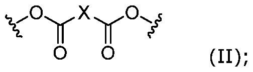 wherein represents a point of connection to chitosan; and
X is optionally substituted alkylene; wherein the hydrogel has a degree of crosslinking of more than about 90%.
24. The method according to claim 23, wherein the backing layer comprises a polymer selected from polycaprolactone, poly(lactic acid) (PLA), thermoplastic polyurethane, polyethylene or a combination thereof.
25. The method according to claim 23 or 24, further comprising a step prior to step a) of providing a wound template for printing the composite.
26. The method according to any one of claims 23 to 25, further comprises printing and crosslinking a barrier layer.
27. The method according to claim 26, wherein the barrier layer is formed by printing and crosslinking gelatin methacrylate.
28. The method according to any one of claims 23 to 27, further comprises printing and crosslinking a filler layer.
29. The method according to any one of claims 23 to 28, further comprises printing and crosslinking a second 3D printed hydrogel layer.
30. The method according to any one of claims 23 to 29, further comprises a step of sterilising the hydrogel ink before printing it on the backing layer.

31. A 3D printed hydrogel comprising chitosan crosslinked with a moiety of Formula (II):
 wherein
 represents a point of connection to chitosan; and
X is optionally substituted alkylene; wherein the hydrogel has a degree of crosslinking of more than about 90%.
32. The hydrogel according to claim 31, the hydrogel having an average pore size of about 5 pm to about 300 pm.
33. The hydrogel according to claim 31 or 32, wherein the hydrogel is characterised by a water content of about 70% to about 200% relative to the hydrogel.
34. The hydrogel according to any one of claims 31 to 33, wherein the hydrogel is characterised by a degradation of about 20 % to about 90% after 3 weeks.
35. A composite, comprising: c) a 3D printed hydrogel layer, the 3D printed hydrogel layer formed from the 3D printed hydrogel according to any one of claims 1 to 11; and d) a backing layer.
36. The composite according to claim 35, wherein the composite comprises at least two 3D printed hydrogel layers.
37. The composite according to claim 35 or 36, wherein the backing layer is 3D printed.
38. The composite according to any one of claims 35 to 37, wherein the backing layer has a thickness of about 0.5 mm to about 3 mm.
39. The composite according to any one of claims 35 to 38, wherein the backing layer forms a border around the 3D printed hydrogel layer.

40. The composite according to claim 39, wherein the border has a thickness of about 1 cm to about 5 cm.
41. A hydrogel ink comprising chitosan functionalised with a moiety of Formula (I):
 (I); wherein
 represents a point of connection to chitosan; and Z is optionally substituted alkenyl.
Applications Claiming Priority (2)
| Application Number | Priority Date | Filing Date | Title |
|---|---|---|---|
| SG10202008411T | 2020-08-31 | ||
| SG10202008411T | 2020-08-31 |
Publications (1)
| Publication Number | Publication Date |
|---|---|
| WO2022045967A1 true WO2022045967A1 (en) | 2022-03-03 |
Family
ID=80352942
Family Applications (1)
| Application Number | Title | Priority Date | Filing Date |
|---|---|---|---|
| PCT/SG2021/050468 Ceased WO2022045967A1 (en) | 2020-08-31 | 2021-08-10 | Hydrogels and methods of fabrication thereof |
Country Status (1)
| Country | Link |
|---|---|
| WO (1) | WO2022045967A1 (en) |
Cited By (3)
| Publication number | Priority date | Publication date | Assignee | Title |
|---|---|---|---|---|
| CN115887733A (en) * | 2022-11-28 | 2023-04-04 | 天津中医药大学 | A kind of 3D printing silver-loaded antibacterial traditional Chinese medicine dressing and preparation method thereof |
| CN117323457A (en) * | 2023-11-10 | 2024-01-02 | 广州贝奥吉因生物科技股份有限公司 | 3D printing band-aid and preparation method thereof |
| CN120818235A (en) * | 2025-09-19 | 2025-10-21 | 中南大学湘雅医院 | A polymer composite hydrogel and preparation method thereof |
Citations (2)
| Publication number | Priority date | Publication date | Assignee | Title |
|---|---|---|---|---|
| CN110664541A (en) * | 2019-09-25 | 2020-01-10 | 北京科技大学 | Preparation method of 3D-printed wound customized band-aid |
| US20200055302A1 (en) * | 2015-11-24 | 2020-02-20 | The Texas A&M University System | In Vivo Live 3D Printing of Regenerative Bone Healing Scaffolds for Rapid Fracture Healing |
-
2021
- 2021-08-10 WO PCT/SG2021/050468 patent/WO2022045967A1/en not_active Ceased
Patent Citations (2)
| Publication number | Priority date | Publication date | Assignee | Title |
|---|---|---|---|---|
| US20200055302A1 (en) * | 2015-11-24 | 2020-02-20 | The Texas A&M University System | In Vivo Live 3D Printing of Regenerative Bone Healing Scaffolds for Rapid Fracture Healing |
| CN110664541A (en) * | 2019-09-25 | 2020-01-10 | 北京科技大学 | Preparation method of 3D-printed wound customized band-aid |
Non-Patent Citations (2)
| Title |
|---|
| SHEN YI; TANG HAIFENG; HUANG XIAOBO; HANG RUIQIANG; ZHANG XIANGYU; WANG YUEYUE; YAO XIAOHONG: "DLP printing photocurable chitosan to build bio-constructs for tissue engineering", CARBOHYDRATE POLYMERS, APPLIED SCIENCE PUBLISHERS , LTD BARKING, GB, vol. 235, 10 February 2020 (2020-02-10), GB , XP086068321, ISSN: 0144-8617, DOI: 10.1016/j.carbpol.2020.115970 * |
| ZHANG HUA, CONG YANG, OSI AMARACHI ROSEMARY, ZHOU YANG, HUANG FANGCHENG, ZACCARIA REMO P., CHEN JING, WANG RONG, FU JUN: "Direct 3D Printed Biomimetic Scaffolds Based on Hydrogel Microparticles for Cell Spheroid Growth", ADVANCED FUNCTIONAL MATERIALS, WILEY - V C H VERLAG GMBH & CO. KGAA, DE, vol. 30, no. 13, 12 February 2020 (2020-02-12), DE , pages 1910573, XP055911218, ISSN: 1616-301X, DOI: 10.1002/adfm.201910573 * |
Cited By (4)
| Publication number | Priority date | Publication date | Assignee | Title |
|---|---|---|---|---|
| CN115887733A (en) * | 2022-11-28 | 2023-04-04 | 天津中医药大学 | A kind of 3D printing silver-loaded antibacterial traditional Chinese medicine dressing and preparation method thereof |
| CN115887733B (en) * | 2022-11-28 | 2024-02-27 | 天津中医药大学 | A 3D printed silver-loaded antibacterial traditional Chinese medicine dressing and its preparation method |
| CN117323457A (en) * | 2023-11-10 | 2024-01-02 | 广州贝奥吉因生物科技股份有限公司 | 3D printing band-aid and preparation method thereof |
| CN120818235A (en) * | 2025-09-19 | 2025-10-21 | 中南大学湘雅医院 | A polymer composite hydrogel and preparation method thereof |
Similar Documents
| Publication | Publication Date | Title |
|---|---|---|
| Teoh et al. | 3D printing personalized, photocrosslinkable hydrogel wound dressings for the treatment of thermal burns | |
| Teoh et al. | Fabricating scalable, personalized wound dressings with customizable drug loadings via 3D printing | |
| Rajkumar et al. | Chitosan-based biomaterial in wound healing: a review | |
| Mirhaj et al. | An antibacterial multi-layered scaffold fabricated by 3D printing and electrospinning methodologies for skin tissue regeneration | |
| EP3243533B1 (en) | Threads of cross-linked hyaluronic acid and methods of use thereof | |
| JP5657545B2 (en) | Method for preparing an injectable hydrogel crosslinked in an injectable container | |
| EP3013865B1 (en) | Method for manufacturing a shaped cross-linked hyaluronic acid product | |
| US20200038544A1 (en) | Dressing | |
| Wang et al. | Antimicrobial hydroxyapatite reinforced-polyelectrolyte complex nanofibers with long-term controlled release activity for potential wound dressing application | |
| WO2022045967A1 (en) | Hydrogels and methods of fabrication thereof | |
| WO2014161085A1 (en) | Schiff-based aldehydic hyaluronic acid-chitosan hydrogel compositions and uses thereof | |
| US8623403B2 (en) | Methods for regulating gelation of hydrogel solutions and uses thereof | |
| Alotaibi et al. | Development of poly (vinyl alcohol)–chitosan composite nanofibers for dual drug therapy of wounds | |
| CN1944495A (en) | Water gel containing natural high molecule and its radiation preparing method | |
| Amarjargal et al. | On-demand sequential release of dual drug from pH-responsive electrospun Janus nanofiber membranes toward wound healing and infection control | |
| Yasin et al. | Composite hydrogels from carrageenan-cl-carboxymethyl chitosan–PVA incorporated ZiF-8 as dressing material for wound healing applications | |
| JP7843051B2 (en) | Biocompatible hydrogel containing hyaluronic acid, polyethylene glycol, and silicone components. | |
| Majidi Ghatar et al. | A novel hydrogel containing 4-methylcatechol for skin regeneration: in vitro and in vivo study | |
| Gupta et al. | Bioresorbable polymers/HNT blend composite wound dressings | |
| Rajan et al. | Biomedical applications of hydroxyapatite nanocomposites | |
| KR20250020813A (en) | Visible light crosslinked hydrogels containing MXene and manufacturing method thereof | |
| Kefayat et al. | 3D printed, biodegradable, and biocompatible intraperitoneal implants loaded with folic acid-targeted/pH-sensitive/doxorubicin-loaded hydroxyapatite nanoparticles for systemic treatment of metastatic breast cancer | |
| Uddin et al. | Algae-based 3D printed hydrogel patch in diabetic wound healing | |
| Chen et al. | Infection protection, immune regulation and epithelial regeneration trifunctional hydrogel for treatment of burn wounds | |
| Khan et al. | PREPARATION AND CHARACTERIZATION OF METRONIDAZOLE-LOADED FILM CONSISTING OF CHITOSAN AND ASCORBIC ACID FOR TOPICAL APPLICATION |
Legal Events
| Date | Code | Title | Description |
|---|---|---|---|
| 121 | Ep: the epo has been informed by wipo that ep was designated in this application |
Ref document number: 21862206 Country of ref document: EP Kind code of ref document: A1 |
|
| NENP | Non-entry into the national phase |
Ref country code: DE |
|
| 122 | Ep: pct application non-entry in european phase |
Ref document number: 21862206 Country of ref document: EP Kind code of ref document: A1 |